ni43-101 technical report on a mineral resource...
TRANSCRIPT

name to work with template script in local application 030613
Report Prepared by
SRK Consulting (UK) Limited UK6540
NI43-101 TECHNICAL REPORT ON A MINERAL RESOURCE ESTIMATE ON
THE OROPESA TIN PROJECT, CORDOBA PROVINCE, SPAIN,
OCTOBER 2015.
Prepared For
Minas de Estaño de España
SRK Consulting Oropesa NI43-101
UK6540 Oropesa NI43-101 Report_Final.docx December 2015
SRK Legal Entity: SRK Consulting (UK) Limited
SRK Address: 5th Floor Churchill House 17 Churchill Way
Cardiff, CF10 2HH Wales, United Kingdom.
Effective Date: 30 October 2015
Report Date: 14 December 2015
Project Number: UK6540
SRK Project Director: Mike Beare Corporate Consultant (Mining Engineering)
SRK Project Manager: Paul Stenhouse (Senior Consultant (Structural Geology)
Client Legal Entity: Minas De Estaño De España
Client Address: Calle Americo Vespucio, 5, Seville,
41092, Spain.
COPYRIGHT AND DISCLAIMER
Copyright (and any other applicable intellectual property rights) in this document and any accompanying data or models which are created by SRK Consulting (UK) Limited ("SRK") is reserved by SRK and is protected by international copyright and other laws. Copyright in any component parts of this document such as images is owned and reserved by the copyright owner so noted within this document.
The use of this document is strictly subject to terms licensed by SRK to the named recipient or recipients of this document or persons to whom SRK has agreed that it may be transferred to (the “Recipients”). Unless otherwise agreed by SRK, this does not grant rights to any third party. This document shall only be distributed to any third party in full as provided by SRK and may not be reproduced or circulated in the public domain (in whole or in part) or in any edited, abridged or otherwise amended form unless expressly agreed by SRK. Any other copyright owner’s work may not be separated from this document, used or reproduced for any other purpose other than with this document in full as licensed by SRK. In the event that this document is disclosed or distributed to any third party, no such third party shall be entitled to place reliance upon any information, warranties or representations which may be contained within this document and the Recipients of this document shall indemnify SRK against all and any claims, losses and costs which may be incurred by SRK relating to such third parties.
This document is issued subject to the confidentiality provisions in SRK’s Terms and Conditions, which are included in the Commercial Appendices and contain mutual confidentiality obligations. Accordingly, any references in the confidentiality provisions in SRK’s Terms and Conditions to the “Client” should be read as “Recipients”. SRK respects the general confidentiality of its potential clients’ confidential information whether formally agreed with them or not and SRK therefore expects the contents of this document to be treated as confidential by the Recipients. The Recipients may not release the technical and pricing information contained in this document or any other documents submitted by SRK to the Recipients, or otherwise make it or them available to any third party without the express written consent of SRK. © SRK Consulting (UK) Limited 2015 version: Jan2015

SRK Consulting (UK) Limited 5th Floor Churchill House 17 Churchill Way City and County of Cardiff CF10 2HH, Wales United Kingdom E-mail: [email protected] URL: www.srk.co.uk Tel: + 44 (0) 2920 348 150 Fax: + 44 (0) 2920 348 199
SRK Consulting (UK) Limited 5th Floor Churchill House 17 Churchill Way City and County of Cardiff CF10 2HH, Wales United Kingdom E-mail: [email protected] URL: www.srk.co.uk Tel: + 44 (0) 2920 348 150 Fax: + 44 (0) 2920 348 199
Registered Address: 21 Gold Tops, City and County of Newport, NP20 4PG, Wales, United Kingdom.
SRK Consulting (UK) Limited Reg No 01575403 (England and Wales) Page 1 of 110
Group Offices: Africa Asia
Australia Europe
North America South America
EXECUTIVE SUMMARY
NI43-101 TECHNICAL REPORT ON A MINERAL RESOURCE ESTIMATE ON THE OROPESA TIN PROJECT, CORDOBA
PROVINCE, SPAIN, OCTOBER 2015.
1 EXECUTIVE SUMMARY 1.1 Introduction
SRK Consulting (UK) Limited (“SRK”) has been requested by Minas De Estaño De España, SLU (“MESPA” or “the Company”) to prepare an update of the Mineral Resource Estimate on the Oropesa Tin Project (“Oropesa” or “the Project”).
During 2015, the Company has focused exploration work towards re-interpreting the geological model and confirming the continuity of the mineralisation within previously non-sampled zones, with a focus on adding further confidence to the associated block grade and tonnage estimates. The deposit has been modelled using the UTM coordinate grid.
The Mineral Resource Statement presented is signed off by Martin Pittuck and Paul Stenhouse, Qualified Persons in accordance with the CIM Code.
1.2 Project Description
The Oropesa property represents a 15.0 km2 concession package located approximately 75 km northwest of Cordoba and 180 km northeast of Seville, Region of Andalucía, in southern Spain. The Company has satisfied all conditions to receive a 100% interest in the Oropesa property and anticipates that registered title to the property will be transferred to the Company within several months of filing the transfer documents with the Andalucia mining authorities under the Spanish Mining Act.
1.3 Project Geology
The Oropesa deposit is located within the Peñarroya basin, a Carboniferous, transtensional basin that formed during the Hercynian/Variscan orogeny.
The Oropesa project area comprises intercalated sandstones and conglomerates with complex geometries, reflecting an active depositional environment and syn-sedimentary faulting. This geometry has been further complicated by a subsequent phase of basin inversion that involved reactivation of some basin-controlling faults as reverse faults and associated folding of the stratigraphic package, producing locally overturned bedding.
SRK Consulting Oropesa NI43-101 –Executive Summary
UK6540 Oropesa NI43-101 Report_Final.docx December 2015 Page 2 of 6
Tin mineralisation (cassiterite with minor stannite) is typically associated with pervasive silica alteration and several phases of paragentically late sulphides. The majority of the tin mineralisation is replacement style, primarily occurring in granular sandstones at the contacts between the sandstone and conglomerate units. Two main faults sets are also interpreted to be mineralised, however fault-hosted mineralisation is volumetrically far less significant than the replacement style mineralisation.
1.4 Exploration Drilling And Sampling
The latest phase of exploration drilling and sampling was a relatively small program aimed at confirming the presence of mineralisation within previously non-sampled zones and testing for additional tin mineralisation at depth below previously modelled domains.
The updated Mineral Resource Estimate for the Oropesa Project is based on some 50,699 m of drilling for a total of 240 drillholes. The drilling has been completed from the surface on a grid spacing of approximately 40–100 m, providing intersections at a similar spacing. Drillholes are typically angled between -45° and -85° (from horizontal), orientated broadly perpendicular to the strike of mineralisation with intersection angles with the mineralisation typically ranging from perpendicular to 45°.
In comparison to the MRE reported in June 2014 (“2014 MRE”), the database includes an additional 980 m of diamond drilling in three drillholes completed during the latest phase of exploration and an additional 754 m in four earlier holes which were not available in time for the 2014 MRE drilling database. In addition, some 47 samples from six drillholes have been submitted for analysis from previously non-sampled drill core. All recent samples were sent for preparation to ALS Laboratories sample preparation facility in Seville, Spain (“ALS Seville”), and then dispatched to ALS Vancouver, Canada (“ALS Vancouver”) for analysis for tin by glass fusion X-Ray fluorescence (“XRF”).
In the opinion of SRK, the sampling procedures used by the Company conform to industry best practices and the resultant drilling pattern is sufficiently dense to interpret the geometry, geological boundaries and tin mineralisation with an appropriate level of confidence.
1.5 Mineral Resource Estimate
For the October 2015 Mineral Resource update, SRK has updated the geological interpretation for the Oropesa Project to reflect a more stratabound and folded mineralisation model. Mineralisation domains have been defined based on a combination of lithological logging and tin grade whilst honouring the structural controls and ensuring geological and grade continuity. Top and bottom contacts reflect a cut-off of 0.25% tin (Sn) to differentiate mineralised layers from lower grade host rock and internal partings.
SRK created 3D solid wireframes from selected sample intervals using the vein tool in the Leapfrog Geo Software (“Leapfrog”).
Mineralisation modelled for October 2015 comprises several separate features, each of which are geologically continuous along strike for between 100 m and 800 m, with dip extents of up to 250 m and an average thickness normally between 3 and 10 m, reaching over 25 m in certain areas.

SRK Consulting Oropesa NI43-101 –Executive Summary
UK6540 Oropesa NI43-101 Report_Final.docx December 2015 Page 3 of 6
The tin grade data shows that there are higher and lower grade zones within the deposit. There are no clearly predictable grade trends from top to bottom contact in the horizons, so SRK elected to create a single composite for each of the drillholes per intersected domain to ensure variography and block grade estimation focus on variability along strike and along dip. Where drillholes intersect the domain at a very shallow angle, several composites were made with a maximum length each of 40 m.
Based on a review of raw and log histogram plots, no high-grade capping was applied. SRK completed a geostatistical analysis on the domain coded composite data; the resultant variogram models have a nugget effect of 14% and maximum range of 70 m.
SRK created a block model with parent block dimensions of 20x20x10 m, with sub blocking to 2.0x2.0x1.0 m. Tin grades have been estimated into parent blocks based on Ordinary Kriging (“OK”) routines with an isotropic search ellipse (65x65x65 m). The search required a minimum of four and a maximum of 8 composite samples, with an expanded search ellipse used to estimate less well-informed blocks that did not satisfy the initial search criteria.
SRK has both visually and statistically validated the estimated block grades which confirm the robustness of the parameters and estimates, with no indication of any significant bias.
1.6 Classification
SRK has considered sampling and assay quality, sampling density and block distance from samples in order to classify the Mineral Resource according to the terminology, definitions and guidelines given in the Canadian Institute of Mining, Metallurgy and Petroleum (“CIM”) Standards on Mineral Resources and Mineral Reserves (May 2014) as required by NI 43-101.
Upon consideration of data quality, geological confidence, sample spacing and the interpreted continuity of grades controlled by the deposit, SRK has classified the block model in both the Indicated and Inferred Mineral Resource categories. Indicated Mineral Resources comprise the blocks in domains which have an elevated level of geological confidence and which are situated within well drilled areas of the model and typically up to 70 m beyond these areas. Inferred Mineral Resources are in domains that display reasonable geological confidence, where blocks are typically within 100 m of sample data. These areas require infill drilling to improve the quality of the geological interpretation and local block grade estimates to a level suitable for mine planning.
1.7 Mineral Resource Statement
SRK has applied basic economic considerations to determine which portion of the block model has reasonable prospects for economic extraction by open-pit mining methods. To achieve this, the Mineral Resource has been subject to a high-level pit optimisation study to assist with determining the potential depth to which an open pit operation could be considered viable and reported above a suitable cut-off grade for resource reporting.
The results of the optimisation study for 2015 showed that an open pit operation could potentially be supported to a depth of 235 m (close to the bottom of the deposit model) and that a lower cut-off grade of 0.1% Sn is appropriate. SRK has elected to consider the full extents of the geological model for resource reporting.
SRK Consulting Oropesa NI43-101 –Executive Summary
UK6540 Oropesa NI43-101 Report_Final.docx December 2015 Page 4 of 6
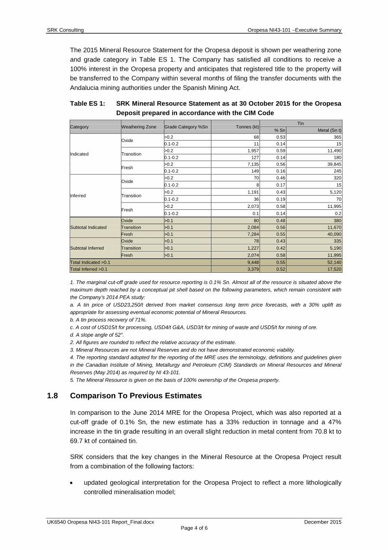
The 2015 Mineral Resource Statement for the Oropesa deposit is shown per weathering zone and grade category in Table ES 1. The Company has satisfied all conditions to receive a 100% interest in the Oropesa property and anticipates that registered title to the property will be transferred to the Company within several months of filing the transfer documents with the Andalucia mining authorities under the Spanish Mining Act.
Table ES 1: SRK Mineral Resource Statement as at 30 October 2015 for the Oropesa Deposit prepared in accordance with the CIM Code
Category Weathering Zone Grade Category %Sn Tonnes (kt) Tin
% Sn Metal (Sn t)
Indicated
Oxide >0.2 68 0.53 365 0.1-0.2 11 0.14 15
Transition >0.2 1,957 0.59 11,490 0.1-0.2 127 0.14 180
Fresh >0.2 7,135 0.56 39,845 0.1-0.2 149 0.16 245
Inferred
Oxide >0.2 70 0.46 320 0.1-0.2 8 0.17 15
Transition >0.2 1,191 0.43 5,120 0.1-0.2 36 0.19 70
Fresh >0.2 2,073 0.58 11,995 0.1-0.2 0.1 0.14 0.2
Subtotal Indicated Oxide >0.1 80 0.48 380 Transition >0.1 2,084 0.56 11,670 Fresh >0.1 7,284 0.55 40,090
Subtotal Inferred Oxide >0.1 78 0.43 335 Transition >0.1 1,227 0.42 5,190 Fresh >0.1 2,074 0.58 11,995
Total Indicated >0.1 9,448 0.55 52,140 Total Inferred >0.1 3,379 0.52 17,520
1. The marginal cut-off grade used for resource reporting is 0.1% Sn. Almost all of the resource is situated above the maximum depth reached by a conceptual pit shell based on the following parameters, which remain consistent with the Company’s 2014 PEA study: a. A tin price of USD23,250/t derived from market consensus long term price forecasts, with a 30% uplift as appropriate for assessing eventual economic potential of Mineral Resources. b. A tin process recovery of 71%. c. A cost of USD15/t for processing, USD4/t G&A, USD3/t for mining of waste and USD5/t for mining of ore. d. A slope angle of 52°. 2. All figures are rounded to reflect the relative accuracy of the estimate. 3. Mineral Resources are not Mineral Reserves and do not have demonstrated economic viability. 4. The reporting standard adopted for the reporting of the MRE uses the terminology, definitions and guidelines given in the Canadian Institute of Mining, Metallurgy and Petroleum (CIM) Standards on Mineral Resources and Mineral Reserves (May 2014) as required by NI 43-101. 5. The Mineral Resource is given on the basis of 100% ownership of the Oropesa property.
1.8 Comparison To Previous Estimates
In comparison to the June 2014 MRE for the Oropesa Project, which was also reported at a cut-off grade of 0.1% Sn, the new estimate has a 33% reduction in tonnage and a 47% increase in the tin grade resulting in an overall slight reduction in metal content from 70.8 kt to 69.7 kt of contained tin.
SRK considers that the key changes in the Mineral Resource at the Oropesa Project result from a combination of the following factors:
• updated geological interpretation for the Oropesa Project to reflect a more lithologically controlled mineralisation model;
SRK Consulting Oropesa NI43-101 –Executive Summary
UK6540 Oropesa NI43-101 Report_Final.docx December 2015 Page 5 of 6
• increase in the wireframe modelling cut-off from 0.1% Sn to 0.25% Sn;
• reporting of additional block model material at depth, supported by the updated pit optimisation exercise for October 2015, which has driven the conceptual pit deeper when compared to June 2014;
• less mixing of low grades and high grades based on the revised geological interpretation; and
• some additional exploration drilling and the addition of assays from a limited number of previously non-sampled intercepts and sample results which were not available during the previous estimate.
1.9 Conclusions
The Oropesa deposit is an open pit mining target which is at a relatively advanced stage of drilling and geological understanding. This resource estimate suggests there is a significant body of mineralisation which occurs within 265 m of surface; however, more work is required to confirm this and to fully evaluate the potential for a mining project.
The improved geological interpretation used to generate the model for the 2015 Mineral Resource estimate is generally considered to be robust; however, there are areas of lower geological confidence which may be subject to further revision in the future. SRK considers the exploration data accumulated by the Company is generally reliable and suitable for the purpose of this Mineral Resource estimate.
The economic viability of the Oropesa Project will need to be fully addressed in further technical studies.
1.10 Recommendations
SRK considers there to be good potential to improve confidence and increase tonnage in the reported Mineral Resource at Oropesa with further modelling work and additional drilling. In relation to drilling and sampling, SRK would recommend the following:
• Infill drilling to add geological confidence to convert the Inferred Resources to Indicated and convert some of the Indicated to Measured Resources. SRK has not proposed a detailed infill drilling program, however considers a budget in the order of magnitude of USD10m (to double the drilling completed to date) should achieve this.
• Complete additional exploration drilling along strike and around the margins of the deposit where there is potential to add additional replacement-style and/or fault-controlled mineralisation. Any future drilling should include the systematic collection of downhole structural data to further constrain the geological model.
• Furthermore, the updated geological model used to guide the development of the mineralisation wireframes has significant implications for exploration in the surrounding area. The geological model should be further tested and refined in conjunction with a reassessment of the licence scale exploration potential.
• Complete further metallurgical testwork to improve the current understanding of the potential process recovery for tin, which impacts on the technical parameters used for reporting of the Oropesa Mineral Resource.

SRK Consulting Oropesa NI43-101 –Executive Summary
UK6540 Oropesa NI43-101 Report_Final.docx December 2015 Page 6 of 6
In relation to further modelling work, SRK would recommend modelling the lower grade material (between 0.1 – 0.25% Sn) that occurs in certain areas adjacent to the current Resource model which would add marginal material to the Resource.
In addition, SRK would also recommend the following:
• Update the July 2014 PEA on the basis of the updated Mineral Resource Estimate.
• Adopt a commercial database system to improve the overall database management at Oropesa.
• For the holes drilled prior to ORPD059 (if available) SRK recommend to send pulp splits from a representative portion of samples to the primary laboratory along with QAQC samples according to the current protocols to compare the laboratory performance today with its performance in 2011 and 2010 prior to drillhole ORPD059.
SRK Consulting Oropesa NI43-101 – Table of Contents Main Report
UK6540 Oropesa NI43-101 Report_Final.docx December 2015 Page i of vi
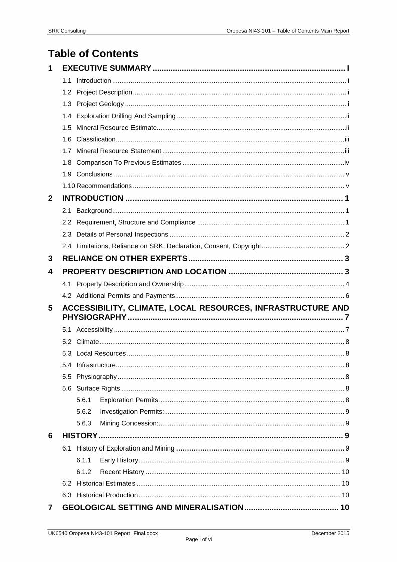
Table of Contents 1 EXECUTIVE SUMMARY ...................................................................................... I
1.1 Introduction ............................................................................................................................... i
1.2 Project Description .................................................................................................................... i
1.3 Project Geology ........................................................................................................................ i
1.4 Exploration Drilling And Sampling ............................................................................................ii
1.5 Mineral Resource Estimate.......................................................................................................ii 1.6 Classification ............................................................................................................................ iii
1.7 Mineral Resource Statement ................................................................................................... iii
1.8 Comparison To Previous Estimates ........................................................................................iv
1.9 Conclusions ............................................................................................................................. v
1.10 Recommendations ................................................................................................................... v
2 INTRODUCTION ................................................................................................. 1
2.1 Background .............................................................................................................................. 1 2.2 Requirement, Structure and Compliance ................................................................................ 1
2.3 Details of Personal Inspections ............................................................................................... 2
2.4 Limitations, Reliance on SRK, Declaration, Consent, Copyright ............................................. 2
3 RELIANCE ON OTHER EXPERTS ..................................................................... 3
4 PROPERTY DESCRIPTION AND LOCATION ................................................... 3
4.1 Property Description and Ownership ....................................................................................... 4
4.2 Additional Permits and Payments ............................................................................................ 6
5 ACCESSIBILITY, CLIMATE, LOCAL RESOURCES, INFRASTRUCTURE AND PHYSIOGRAPHY ................................................................................................ 7
5.1 Accessibility ............................................................................................................................. 7
5.2 Climate ..................................................................................................................................... 8
5.3 Local Resources ...................................................................................................................... 8
5.4 Infrastructure ............................................................................................................................ 8
5.5 Physiography ........................................................................................................................... 8
5.6 Surface Rights ......................................................................................................................... 8 5.6.1 Exploration Permits: .................................................................................................... 8
5.6.2 Investigation Permits:.................................................................................................. 9
5.6.3 Mining Concession: ..................................................................................................... 9
6 HISTORY ............................................................................................................. 9
6.1 History of Exploration and Mining ............................................................................................ 9
6.1.1 Early History ................................................................................................................ 9
6.1.2 Recent History .......................................................................................................... 10 6.2 Historical Estimates ............................................................................................................... 10
6.3 Historical Production .............................................................................................................. 10
7 GEOLOGICAL SETTING AND MINERALISATION .......................................... 10

SRK Consulting Oropesa NI43-101 – Table of Contents Main Report
UK6540 Oropesa NI43-101 Report_Final.docx December 2015 Page ii of vi
7.1 Regional Geology .................................................................................................................. 10
7.2 Local/Project Geology ............................................................................................................ 13
7.2.1 Stratigraphy ............................................................................................................... 13 7.2.2 Structure ................................................................................................................... 14
7.2.3 Mineralisation ............................................................................................................ 16
8 DEPOSIT TYPES .............................................................................................. 18
9 EXPLORATION ................................................................................................. 18
9.1 Historical Exploration ............................................................................................................. 18
9.1.1 Regional Geological Mapping ................................................................................... 19
9.1.2 Regional Geochemical Stream Sediment Surveys ................................................... 19
9.1.3 Regional Geochemical Soil Surveys ......................................................................... 20 9.1.4 Regional Geophysical Surveys ................................................................................. 21
9.1.5 Local Geochemical Soil Surveys .............................................................................. 21
9.1.6 Oropesa Trenching and Sampling ............................................................................ 23
9.1.7 Local Drilling ............................................................................................................. 23
9.1.8 Mineralogical Studies ................................................................................................ 23
9.2 Exploration by the Company ................................................................................................. 23 9.2.1 Geochemical Survey ................................................................................................. 23
9.2.2 Geophysical Surveys ................................................................................................ 23
9.2.3 Trenching Programmes ............................................................................................ 24
9.2.4 Test Pitting Programmes .......................................................................................... 24
10 DRILLING .......................................................................................................... 24
10.1 Historical Drilling .................................................................................................................... 24 10.2 Drilling by the Company......................................................................................................... 25
10.2.1 Drilling Summary 2010.............................................................................................. 25
10.2.2 Drilling Summary 2011.............................................................................................. 25
10.2.3 Drilling Summary 2012.............................................................................................. 26
10.2.4 Drilling Summary 2013.............................................................................................. 26
10.2.5 Drilling Summary 2015.............................................................................................. 26 10.2.6 Summary of Data Quantity ....................................................................................... 27
10.2.7 Collar Surveys ........................................................................................................... 27
10.2.8 Downhole Surveys .................................................................................................... 27
10.2.9 Hole Orientation ........................................................................................................ 28
10.2.10 Diamond Drilling Procedure ...................................................................................... 28
10.2.11 Core Recovery .......................................................................................................... 29 10.2.12 Core Storage ............................................................................................................. 29
10.3 SRK Comments ..................................................................................................................... 30
11 SAMPLE PREPARATION, ANALYSIS AND SECURITY ................................. 30
11.1 Introduction ............................................................................................................................ 30
SRK Consulting Oropesa NI43-101 – Table of Contents Main Report
UK6540 Oropesa NI43-101 Report_Final.docx December 2015 Page iii of vi
11.2 Chain of Custody, Sample Preparation, and Analyses ......................................................... 30
11.3 Specific Gravity Data ............................................................................................................. 30
11.4 SRK Comments ..................................................................................................................... 32
12 DATA VERIFICATION ....................................................................................... 32
12.1 Verifications by SRK .............................................................................................................. 32
12.1.1 Verification of Sampling Database ............................................................................ 32
12.2 Verifications by the Company ................................................................................................ 33
12.3 QAQC for Tin Analysis 2010-2013 ........................................................................................ 34
12.3.1 Insertion of CRM ....................................................................................................... 34
12.3.2 Blanks ....................................................................................................................... 34 12.3.3 Duplicates ................................................................................................................. 35
12.3.4 Umpire Laboratory Duplicates .................................................................................. 35
12.4 QAQC for Tin Analysis 2015.................................................................................................. 35
12.4.1 Insertion of CRM ....................................................................................................... 36
12.4.2 Blanks ....................................................................................................................... 36
12.4.3 Duplicates ................................................................................................................. 36 12.5 SRK Comments ..................................................................................................................... 37
13 MINERAL PROCESSING AND METALLURGICAL TESTING ......................... 37
14 MINERAL RESOURCE ESTIMATES ................................................................ 40
14.1 Introduction ............................................................................................................................ 40
14.2 Resource Estimation Procedures .......................................................................................... 40
14.3 Resource Database ............................................................................................................... 40
14.4 Statistical Analysis – Raw Data ............................................................................................. 40 14.5 3D Modelling .......................................................................................................................... 41
14.5.1 Geological Wireframes.............................................................................................. 41
14.5.2 Mineralisation Wireframes ........................................................................................ 42
14.5.3 Mineralisation Model Coding .................................................................................... 42
14.6 Compositing ........................................................................................................................... 44
14.7 Evaluation of Outliers ............................................................................................................. 44 14.8 Geostatistical Analysis ........................................................................................................... 45
14.9 Block Model and Grade Estimation ....................................................................................... 47
14.10 Final Estimation Parameters ............................................................................................ 48
14.11 Model Validation and Sensitivity ....................................................................................... 48
14.11.1 Sensitivity Analysis ................................................................................................... 48
14.12 Block Model Validation ..................................................................................................... 49 14.13 Mineral Resource Classification ....................................................................................... 52
14.14 Mineral Resource Statement ............................................................................................ 54
14.15 Grade Sensitivity Analysis ................................................................................................ 55
14.16 Vertical Profile Analysis .................................................................................................... 56
SRK Consulting Oropesa NI43-101 – Table of Contents Main Report
UK6540 Oropesa NI43-101 Report_Final.docx December 2015 Page iv of vi
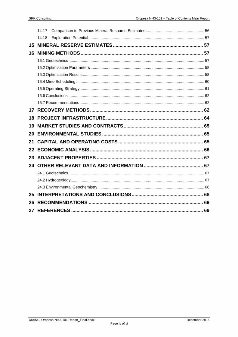
14.17 Comparison to Previous Mineral Resource Estimates ..................................................... 56
14.18 Exploration Potential ......................................................................................................... 57
15 MINERAL RESERVE ESTIMATES ................................................................... 57
16 MINING METHODS ........................................................................................... 57
16.1 Geotechnics ........................................................................................................................... 57 16.2 Optimisation Parameters ....................................................................................................... 58
16.3 Optimisation Results .............................................................................................................. 58
16.4 Mine Scheduling .................................................................................................................... 60
16.5 Operating Strategy ................................................................................................................. 61
16.6 Conclusions ........................................................................................................................... 62
16.7 Recommendations ................................................................................................................. 62
17 RECOVERY METHODS .................................................................................... 62
18 PROJECT INFRASTRUCTURE ........................................................................ 64
19 MARKET STUDIES AND CONTRACTS ........................................................... 65
20 ENVIRONMENTAL STUDIES ........................................................................... 65
21 CAPITAL AND OPERATING COSTS ............................................................... 65
22 ECONOMIC ANALYSIS .................................................................................... 66
23 ADJACENT PROPERTIES ............................................................................... 67
24 OTHER RELEVANT DATA AND INFORMATION ............................................ 67
24.1 Geotechnics ........................................................................................................................... 67
24.2 Hydrogeology ......................................................................................................................... 67
24.3 Environmental Geochemistry ................................................................................................ 68
25 INTERPRETATIONS AND CONCLUSIONS ..................................................... 68
26 RECOMMENDATIONS ..................................................................................... 69
27 REFERENCES .................................................................................................. 69
SRK Consulting Oropesa NI43-101 – Table of Contents Main Report
UK6540 Oropesa NI43-101 Report_Final.docx December 2015 Page v of vi
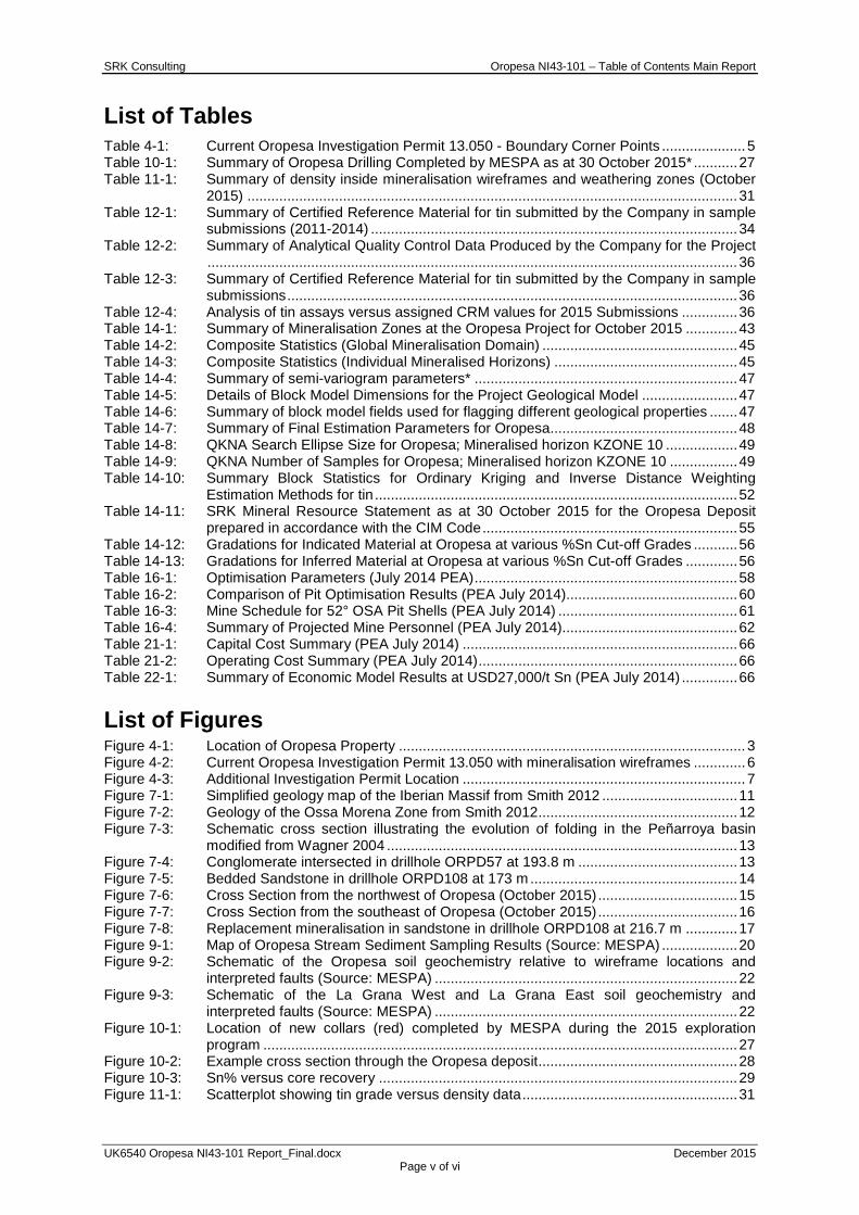
List of Tables Table 4-1: Current Oropesa Investigation Permit 13.050 - Boundary Corner Points ..................... 5 Table 10-1: Summary of Oropesa Drilling Completed by MESPA as at 30 October 2015* ........... 27 Table 11-1: Summary of density inside mineralisation wireframes and weathering zones (October
2015) ........................................................................................................................... 31 Table 12-1: Summary of Certified Reference Material for tin submitted by the Company in sample
submissions (2011-2014) ............................................................................................ 34 Table 12-2: Summary of Analytical Quality Control Data Produced by the Company for the Project
..................................................................................................................................... 36 Table 12-3: Summary of Certified Reference Material for tin submitted by the Company in sample
submissions ................................................................................................................. 36 Table 12-4: Analysis of tin assays versus assigned CRM values for 2015 Submissions .............. 36 Table 14-1: Summary of Mineralisation Zones at the Oropesa Project for October 2015 ............. 43 Table 14-2: Composite Statistics (Global Mineralisation Domain) ................................................. 45 Table 14-3: Composite Statistics (Individual Mineralised Horizons) .............................................. 45 Table 14-4: Summary of semi-variogram parameters* .................................................................. 47 Table 14-5: Details of Block Model Dimensions for the Project Geological Model ........................ 47 Table 14-6: Summary of block model fields used for flagging different geological properties ....... 47 Table 14-7: Summary of Final Estimation Parameters for Oropesa ............................................... 48 Table 14-8: QKNA Search Ellipse Size for Oropesa; Mineralised horizon KZONE 10 .................. 49 Table 14-9: QKNA Number of Samples for Oropesa; Mineralised horizon KZONE 10 ................. 49 Table 14-10: Summary Block Statistics for Ordinary Kriging and Inverse Distance Weighting
Estimation Methods for tin ........................................................................................... 52 Table 14-11: SRK Mineral Resource Statement as at 30 October 2015 for the Oropesa Deposit
prepared in accordance with the CIM Code ................................................................ 55 Table 14-12: Gradations for Indicated Material at Oropesa at various %Sn Cut-off Grades ........... 56 Table 14-13: Gradations for Inferred Material at Oropesa at various %Sn Cut-off Grades ............. 56 Table 16-1: Optimisation Parameters (July 2014 PEA) .................................................................. 58 Table 16-2: Comparison of Pit Optimisation Results (PEA July 2014)........................................... 60 Table 16-3: Mine Schedule for 52° OSA Pit Shells (PEA July 2014) ............................................. 61 Table 16-4: Summary of Projected Mine Personnel (PEA July 2014)............................................ 62 Table 21-1: Capital Cost Summary (PEA July 2014) ..................................................................... 66 Table 21-2: Operating Cost Summary (PEA July 2014) ................................................................. 66 Table 22-1: Summary of Economic Model Results at USD27,000/t Sn (PEA July 2014) .............. 66
List of Figures Figure 4-1: Location of Oropesa Property ....................................................................................... 3 Figure 4-2: Current Oropesa Investigation Permit 13.050 with mineralisation wireframes ............. 6 Figure 4-3: Additional Investigation Permit Location ....................................................................... 7 Figure 7-1: Simplified geology map of the Iberian Massif from Smith 2012 .................................. 11 Figure 7-2: Geology of the Ossa Morena Zone from Smith 2012 .................................................. 12 Figure 7-3: Schematic cross section illustrating the evolution of folding in the Peñarroya basin
modified from Wagner 2004 ........................................................................................ 13 Figure 7-4: Conglomerate intersected in drillhole ORPD57 at 193.8 m ........................................ 13 Figure 7-5: Bedded Sandstone in drillhole ORPD108 at 173 m .................................................... 14 Figure 7-6: Cross Section from the northwest of Oropesa (October 2015) ................................... 15 Figure 7-7: Cross Section from the southeast of Oropesa (October 2015) ................................... 16 Figure 7-8: Replacement mineralisation in sandstone in drillhole ORPD108 at 216.7 m ............. 17 Figure 9-1: Map of Oropesa Stream Sediment Sampling Results (Source: MESPA) ................... 20 Figure 9-2: Schematic of the Oropesa soil geochemistry relative to wireframe locations and
interpreted faults (Source: MESPA) ............................................................................ 22 Figure 9-3: Schematic of the La Grana West and La Grana East soil geochemistry and
interpreted faults (Source: MESPA) ............................................................................ 22 Figure 10-1: Location of new collars (red) completed by MESPA during the 2015 exploration
program ....................................................................................................................... 27 Figure 10-2: Example cross section through the Oropesa deposit .................................................. 28 Figure 10-3: Sn% versus core recovery .......................................................................................... 29 Figure 11-1: Scatterplot showing tin grade versus density data ...................................................... 31

SRK Consulting Oropesa NI43-101 – Table of Contents Main Report
UK6540 Oropesa NI43-101 Report_Final.docx December 2015 Page vi of vi
Figure 12-1: Composite sample grade log histogram distributions for tin, showing data assayed with QAQC support (left) and without QAQC (right) .................................................... 33
Figure 14-1: Incremental and Log Histogram of Length Weighted Project Tin Assays ................... 41 Figure 14-2: 3D view (looking NE) illustrating the position and orientation of the mineralised
horizons and faulting at Oropesa ................................................................................ 42 Figure 14-3: Oropesa Mineralisation Model Cross Section, 25 m slice width ................................. 43 Figure 14-4: Oropesa Mineralisation Model Plan View ................................................................... 44 Figure 14-5: Log Histogram and Log Probability Plot for the tin mineralisation domain at Oropesa
..................................................................................................................................... 45 Figure 14-6: Summary of modelled semi-variogram parameters for the Oropesa Mineralisation
domain (GROUP 100) ................................................................................................. 46 Figure 14-7: Oropesa Block Model 3D view showing visual validation of modelled borehole
intercepts to grade estimates ...................................................................................... 50 Figure 14-8: Validation Plot (Easting) showing Block Model Estimates versus Sample Mean (20m
Intervals) for Mineralised horizon KZONE 10 .............................................................. 51 Figure 14-9: Plan view showing SRK’s wireframe-defined Mineral Resource Classification for the
Oropesa deposit; October 2015 .................................................................................. 53 Figure 16-1: Pit Optimisation Results for 52° slope angle (PEA July 2014) .................................... 59 Figure 17-1: Preliminary Oropesa Sulphide Processing Flowsheet (PEA July 2014) ..................... 63 List of Technical Appendices A QAQC ANALYSIS ............................................................................................A-1
B HISTOGRAMS AND LOG PROBABILITY PLOTS ..........................................B-1
C BLOCK GRADE VISUAL VALIDATION ..........................................................C-1
D VALIDATION PLOTS .......................................................................................D-1
E VERTICAL PROFILE ANALYSIS .................................................................... E-1
F CERTIFICATES OF QUALIFIED PERSONS ................................................... F-1
SRK Consulting (UK) Limited 5th Floor Churchill House 17 Churchill Way City and County of Cardiff CF10 2HH, Wales United Kingdom E-mail: [email protected] URL: www.srk.co.uk Tel: + 44 (0) 2920 348 150 Fax: + 44 (0) 2920 348 199
Registered Address: 21 Gold Tops, City and County of Newport, NP20 4PG, Wales, United Kingdom.
SRK Consulting (UK) Limited Reg No 01575403 (England and Wales) Page 1 of 110
Group Offices: Africa Asia
Australia Europe
North America South America
NI43-101 TECHNICAL REPORT ON A MINERAL RESOURCE ESTIMATE ON THE OROPESA TIN PROJECT, CORDOBA
PROVINCE, SPAIN, OCTOBER 2015.
2 INTRODUCTION 2.1 Background
SRK Consulting (UK) Limited (“SRK”) has been requested by Minas De Estaño De España, SLU (“MESPA” or “the Company”) to prepare an update of the Mineral Resource Estimate on the Oropesa Tin Project (“Oropesa” or “the Project”).
The Oropesa property represents a 15.0 km2 concession package located approximately 75 km northwest of Cordoba and 180 km northeast of Seville, Region of Andalucía, in southern Spain.
The Company reports that it has satisfied all conditions to receive a 100% interest in the Oropesa property and anticipates that registered title to the property will be transferred to the Company within several months of filing the transfer documents with the Andalucia mining authorities under the Spanish Mining Act.
SRK first produced a Mineral Resource Estimate (“MRE”) for the Project in October 2012, updated this in June 2014 and provides this October 2015 update based on further drilling and geological interpretation. This technical report (the Technical Report) has been prepared following the guidelines of the Canadian Securities Administrators’ National Instrument 43-101 and Form 43-101F1 and presents the most up to date MRE, which is based on some 50,699 m of drilling for a total of 240 drillholes.
The latest phase of exploration work completed by the Company has been focused towards re-interpreting the geological model and confirming the continuity of the mineralisation within previously non-sampled zones, with an aim of adding further confidence to the associated block grade and tonnage estimates.
2.2 Requirement, Structure and Compliance
The reporting standards adopted for the reporting of the MRE are the Canadian Institute of Mining, Metallurgy and Petroleum (“CIM”) Definition Standards for Mineral Resources and Mineral Reserves (adopted May 2014) (the CIM Code). The CIM Code is an internationally recognised reporting code as defined by the Combined Reserves International Reporting Standards Committee (CRIRSCO).

SRK Consulting Oropesa NI43-101 – Main Report
UK6540 Oropesa NI43-101 Report_Final.docx December 2015 Page 2 of 70
The Qualified Persons (“QP”) responsible for this report are Dr Paul Stenhouse and Mr Martin Pittuck. Dr Stenhouse assumes responsibility for the site visit inspection, sample database and geological model whilst Mr Pittuck assumes responsibility for the resource estimation procedures and the report as a whole.
2.3 Details of Personal Inspections
This report is based on information collected by SRK during a site visit and fieldwork performed between 20 and 30 August 2015 by Paul Stenhouse and on additional information provided by the Company throughout the course of SRK’s investigations. Other information was obtained from the public domain.
2.4 Limitations, Reliance on SRK, Declaration, Consent, Copyright
SRK’s opinion contained herein and effective 30 October 2015, is based on information collected by SRK throughout the course of SRK’s investigations, which in turn reflect various technical and economic conditions at the time of writing. Given the nature of the mining business, these conditions can change significantly over relatively short periods of time. Consequently, actual results may be significantly more or less favourable.
This report may include technical information that requires subsequent calculations to derive sub-totals, totals and weighted averages. Such calculations inherently involve a degree of rounding and consequently introduce a margin of error. Where these occur, SRK does not consider them to be material.
SRK is not an insider, associate or an affiliate of the Company, and neither SRK nor any affiliate has acted as advisor to the Company, its subsidiaries or its affiliates in connection with this project. The results of the technical review by SRK are not dependent on any prior agreements concerning the conclusions to be reached, nor are there any undisclosed understandings concerning any future business dealings.
Except as specifically required by law, SRK does not assume any responsibility and will not accept any liability to any other person for any loss suffered by any such other person as a result of, arising out of, or in connection with this Technical Report or statements contained herein, required by and given solely for the purpose of complying with the mandate as outlined in this Technical Report and compliance with NI 43-101. SRK has no reason to believe that any material facts have been withheld by the Company.
This report is intended to be read as a whole, and sections should not be read or relied upon out of context. The technical report contains expressions of the professional opinion of the Qualified Person based upon information available at the time of preparation.
SRK Consulting Oropesa NI43-101 – Main Report
UK6540 Oropesa NI43-101 Report_Final.docx December 2015 Page 3 of 70
3 RELIANCE ON OTHER EXPERTS This technical report is effective as of 30 October 2015, it is based on information provided by the Company and its consultants. SRK has visited site to confirm the authenticity, quality and completeness of the technical data on which the Mineral Resource Estimate is based. The report reflects various technical and economic conditions at the time of writing.
SRK has not performed an independent verification of land title and tenure as summarised in Section 4.1 of this report. SRK did not verify the legality of any underlying agreement(s) that may exist concerning the permits or other agreement(s) between third parties, but has relied on the Company and its legal advisor for land title issues. SRK has not performed an independent verification of the metallurgical testwork results as summarised in Section 13.
SRK was informed by the Company that there are no known litigations potentially affecting the Oropesa Project.
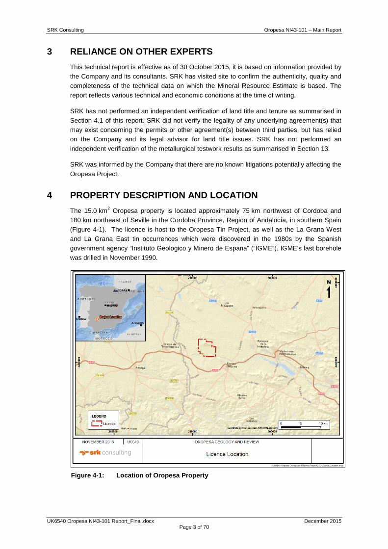
4 PROPERTY DESCRIPTION AND LOCATION The 15.0 km2 Oropesa property is located approximately 75 km northwest of Cordoba and 180 km northeast of Seville in the Cordoba Province, Region of Andalucía, in southern Spain (Figure 4-1). The licence is host to the Oropesa Tin Project, as well as the La Grana West and La Grana East tin occurrences which were discovered in the 1980s by the Spanish government agency “Instituto Geologico y Minero de Espana” (“IGME”). IGME's last borehole was drilled in November 1990.
Figure 4-1: Location of Oropesa Property
SRK Consulting Oropesa NI43-101 – Main Report
UK6540 Oropesa NI43-101 Report_Final.docx December 2015 Page 4 of 70
4.1 Property Description and Ownership
The Oropesa Investigation Permit number 13.050 (the “Permit”), is comprised of 50 “cuadricula mineras”, (blocks of land which measure 0°00’20” per side). Approximate geographical co-ordinates for the centre of the property are latitude 19°00.0’ north and longitude 5°28.5’ west.
The Permit was issued to Sondeos y Perforaciones Industrales del Bierzo, S.A. (SPIB) in January 2008. Pursuant to a Sale and Purchase Agreement (the “SPA”) dated 30 January 2013, SPIB agreed to transfer to Minas De Estano De Espana, SLU (“MESPA”), a 100% interest in the permit. Also, as of 30 January 2013, MESPA and SPIB entered into a Shareholder Agreement (the Sale and Purchase Agreement and the Shareholder Agreement collectively referred to herein as the “Agreements”) relating to their respective continuing interests in the Oropesa property.
MESPA was originally granted the rights to acquire the Permit by SPIB in December 2007. It was agreed by the parties that MESPA would acquire a 50% interest by spending EUR1,500,000 on exploration on the Oropesa property and a further 50% interest by:
1. either granting SPIB a 1.35% net smelter royalty (“NSR”) or paying SPIB 0.90% of the value of the metal reserves in the Oropesa Tin Property; and
2. agreeing to issue to SPIB a 4% equity ownership in MESPA at the time of commercial production.
MESPA satisfied all of the foregoing requirements which, in the case of item 1 above, were satisfied by granting a 1.35% NSR and, as such, the parties have entered into the Agreements to complete the transfer to MESPA of the Permit.
The salient terms of the Agreements included:
1. A transfer to MESPA of a 100% interest in the Permit.
2. MESPA agrees to deliver a scoping study for the Oropesa Tin Property (the “Scoping Study”) by July 2014 (which has been completed).
3. MESPA shall pay to SPIB a 1.35% NSR from the sale of tin concentrate from the Oropesa Tin Property
4. Upon determination of the feasibility of the project, SPIB shall be issued common shares of MESPA so that SPIB becomes a 4% shareholder of MESPA, which percentage ownership shall be fixed and not subject to further dilution.
5. MESPA and SPIB shall establish a technical committee consisting of three individuals, two of which shall be appointed by MESPA and one by SPIB. Until delivery of the Scoping Study, all decisions of the technical committee must be unanimous; however, any lack of unanimity cannot delay advancement of the Scoping Study or other project related work. Following delivery of the Scoping Study, all decisions of the technical committee shall be effective if taken by a majority of its members.
6. SPIB shall be contracted by MESPA for all drilling on the Oropesa Tin Property subject to SPIB’s capacity to fulfil MESPA’s requirements and competitive pricing for its services.

SRK Consulting Oropesa NI43-101 – Main Report
UK6540 Oropesa NI43-101 Report_Final.docx December 2015 Page 5 of 70
7. For all other works and matters to do with the commercial exploitation of the Oropesa Tin Property, excluding plant construction, SPIB shall be given the opportunity to participate in an open tender process. The results from the open tender process will be kept confidential from SPIB and, to the extent that SPIB has presented a bid, SPIB will not participate in the decision making process of the technical committee. If however (i) SPIB’s quotes for any contract or work are competitive and not more than 2% greater than those of an unrelated third party, and (ii) SPIB can demonstrate that it has equal or better technical ability and equipment to fulfil the contract or work, MESPA agrees to give preferential treatment to use SPIB as the contractor.
The Permit was issued for base and precious metals according to Section “C” of the Spanish Mining Act. The boundary of the Oropesa property is not required to be surveyed; it is defined (in accordance with Spanish law) by geographical co-ordinates, provided in Table 4-1. The Permit overlies a section of the Investigation Permit Guadiato IV, and to the east meets the State Reserve 379 both of which were issued for coal under Section “D” of the Spanish Mining Act.
Figure 4-2 shows the current exploration Licence in relation to the mineralisation wireframes, showing the modelled mineralisation within the Licence boundary.
Table 4-1: Current Oropesa Investigation Permit 13.050 - Boundary Corner Points Point West Longtitude North Latitude
1 5°30'00" 38°20'00" 2 5°28'40" 38°20'00" 3 5°28'40" 38°19'40" 4 5°27'40" 38°19'40" 5 5°27'40" 38°19'00" 6 5°27'00" 38°19'00" 7 5°27'00" 38°17'40" 8 5°29'00" 38°17'40" 9 5°29'00" 38°18'00" 10 5o29'40" 38°18'00" 11 5°29'40" 38°18'20" 12 5°30'00" 38°18'20"

SRK Consulting Oropesa NI43-101 – Main Report
UK6540 Oropesa NI43-101 Report_Final.docx December 2015 Page 6 of 70
Figure 4-2: Current Oropesa Investigation Permit 13.050 with mineralisation
wireframes
The Oropesa Investigation Permit was officially renewed on 28 October 2014 for a third period of three years.
The Junta de Andalucia has a policy requiring a reduction in the size of Investigation Permits should be made at the time of their third renewal. Approximately 36% of the licence area has consequently now been relinquished, the Company’s geologists are confident that the areas relinquished had little or no tin mineralisation potential. The Oropesa licence area is now 50 cuadriculas (15 km2), as opposed to 78 cuadriculas (23.4 km2) previously.
SRK has been informed by the client that the current three year Oropesa Investigation Permit expires on October 20, 2017. Thereafter, it is renewable on an annual basis, assuming sufficient work has been completed during the license period. The Client understands that sufficient work has been completed since October 20, 2014 for the license renewal to be successfully made. The company intends to pursue a 30 year exploitation licence and believes it is sufficiently advanced to be able to make a successful application for such a licence and expects to do so in 2016.
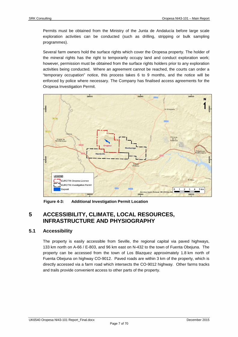
4.2 Additional Permits and Payments
Two additional investigation permits, as illustrated in Figure 4-3, have been conditionally granted to the Company and include:
• PI Montuenga (#13.077), being approximately 14.4 km2 and comprising of 48 cuadricula mineras located to the east of Oropesa; and
• PI Membrillo (#13.081), being approximately 12.7 km2 and comprising of 41 cuadricula mineras located to the south of Oropesa.
SRK Consulting Oropesa NI43-101 – Main Report
UK6540 Oropesa NI43-101 Report_Final.docx December 2015 Page 7 of 70
Permits must be obtained from the Ministry of the Junta de Andalucía before large scale exploration activities can be conducted (such as drilling, stripping or bulk sampling programmes).
Several farm owners hold the surface rights which cover the Oropesa property. The holder of the mineral rights has the right to temporarily occupy land and conduct exploration work; however, permission must be obtained from the surface rights holders prior to any exploration activities being conducted. Where an agreement cannot be reached, the courts can order a “temporary occupation” notice, this process takes 6 to 9 months, and the notice will be enforced by police where necessary. The Company has finalised access agreements for the Oropesa Investigation Permit.
Figure 4-3: Additional Investigation Permit Location
5 ACCESSIBILITY, CLIMATE, LOCAL RESOURCES, INFRASTRUCTURE AND PHYSIOGRAPHY
5.1 Accessibility
The property is easily accessible from Seville, the regional capital via paved highways, 133 km north on A-66 / E-803, and 96 km east on N-432 to the town of Fuenta Obejuna. The property can be accessed from the town of Los Blazquez approximately 1.8 km north of Fuenta Obejuna on highway CO-9012. Paved roads are within 3 km of the property, which is directly accessed via a farm road which intersects the CO-9012 highway. Other farms tracks and trails provide convenient access to other parts of the property.
SRK Consulting Oropesa NI43-101 – Main Report
UK6540 Oropesa NI43-101 Report_Final.docx December 2015 Page 8 of 70
5.2 Climate
The region has a Mediterranean climate which has short mild winters, and long, hot, dry summers. The daily temperatures average 12°C from December to February; during the summer months (July and August) an average temperature of 28°C is experienced. Precipitation is limited to approximately 640 mm annually, half of which falls from January to March. Exploration and mining practices (open pit and underground) are typically conducted year round.
5.3 Local Resources
The property is located close to the regional capital of Seville, and to the cities of Huelva, Cordoba and the former coal mining town of Penarroya-Pueblonuevo. The Andalucia Region has a long mining history and supplies, services and professional, skilled and semi-skilled labour are easily sourced from the cities/towns described previously, for both exploration and mining. The area is currently used for sheep and pig farming, with minor plantations of grain crops.
5.4 Infrastructure
The area is well serviced with paved dual and multi-lane highways, there are also gravel roads and farm tracks throughout the area. The district has power transmission lines which have different voltage capacities. There is a rail head in the town of Penarroya-Pueblonuevo approximately 16 km away.
5.5 Physiography
The local topography is typically gently rolling hills, elevations on the property range from approximately 550 m at the eastern boundary of the property to approximately 811 m at the top of the Sierra de la Grana in the northern part of the property. Sierra de la Grana is thickly covered in jara bushes, whilst the rest of the property is sparsely vegetated with thorn bushes, other shrubs and oak trees.
Several seasonal water courses run through the property. Whilst these are anticipated to be suitable for exploration activities additional water source will be required for mining operation requirements.
5.6 Surface Rights
Under the Spanish Mining Act (1973) land titles with respect to mining can be held as either Exploration Permits (Permiso de Exploracion “PE”), Investigation Permits (Permiso de Investigacion “PI”), or as a Mining Concession (Concesion Minera “MC”). These permits and concession areas are comprised of cuadriculas mineras, and all boundaries are aligned with astronomic north-south and east-west.
5.6.1 Exploration Permits:
• Minimum area: 300 cuadriculas mineras, maximum area: 3000 cuadriculas mineras.
• Only allows work which does not significantly change the land to be conducted.
• One year permit, which can be extended once.

SRK Consulting Oropesa NI43-101 – Main Report
UK6540 Oropesa NI43-101 Report_Final.docx December 2015 Page 9 of 70
5.6.2 Investigation Permits:
• Maximum area: 300 cuadriculas mineras.
• Three year permit, which can be extended for two 3-year periods (with justification).
• Work programmes and budgets must be submitted to the government for each year of the three year permit; technical reports detailing all work completed must also be submitted.
• Where work or budgets have been reduced, the permit holder must provide justification.
• Where the government believes insufficient effort has been made at completing proposed programmes, the PI may be revoked.
• Small fee and nominal taxes are payable each year and must be submitted with a summary of works report.
5.6.3 Mining Concession:
• Maximum area: 100 cuadriculas mineras.
• Issued for 30 years, can be extended twice.
• Mining Concessions will generally only constitute a portion of the Investigation Permit
• To obtain Mining Concessions, an economic mineral deposit must be identified and a mining plan, feasibility study, environmental impact study (“EIS”) and restoration plan (“RP”) need to be submitted to the government. The EIS and RP must be approved by the government environment ministry (Consejeria de Medio Ambiente).
• Three year “Suspension of work” may be applied for where the project economics change negatively, re-application is required every three years.
6 HISTORY 6.1 History of Exploration and Mining
6.1.1 Early History
Mining has been occurring in the Ossa-Morena area since at least 2,000 BC. There is evidence that copper-silver (Cu-Ag) deposits were worked by ancient cultures and the Romans mined outcrops containing lead-silver (Pb-Ag) veins and copper-gold (Cu-Au) veins approximately 45 km west of the Oropesa property. Mining activities appeared to cease at the end of the Roman period. The Cu-Ag veins appear to have been mined again during the 1500s and the Pb-Ag veins were again exploited from 1848 to 1945 in the Azuaga-Berlanga area (20 – 30 km west of Oropesa). Small mining operations were probably occurring in the central area of the Oropesa property during medieval times and during the last century, with slag piles and hand dug shafts having been identified. Coal mining was occurring to the east of Oropesa from the mid-1800s until recently.

SRK Consulting Oropesa NI43-101 – Main Report
UK6540 Oropesa NI43-101 Report_Final.docx December 2015 Page 10 of 70
6.1.2 Recent History
IGME, between 1969 and late 1990, conducted multi-discipline exploration programmes over an area which included the current Oropesa property. A summary of the historical exploration and drilling programs completed by IMGE is provided in Section 9.1 and Section 10.1.
6.2 Historical Estimates
SRK has previously produced two Mineral Resource Estimates on the Oropesa Permit with the initial Mineral Resource with effective date of 9 October 2012 reporting an Oxide Indicated Mineral Resource of 1.7 Mt grading 0.33% Sn, a Fresh Indicated Mineral Resource of 7.3 Mt grading 0.31% Sn, an Oxide Inferred Mineral Resource of 2.7 Mt grading 0.22% Sn and a Fresh Inferred Mineral Resource of 6.1 Mt grading 0.28% Sn.
An updated Mineral Resource Estimate was completed by SRK for 5 June 2014 (“2014 MRE”), which reported an Oxide Indicated Mineral Resource of 3.3 Mt grading 0.35% Sn, a Fresh Indicated Mineral Resource of 11.6 Mt grading 0.37% Sn, an Oxide Inferred Mineral Resource of 1.1 Mt grading 0.35% Sn and a Fresh Inferred Mineral Resource of 3.2 Mt grading 0.38% Sn.
6.3 Historical Production
The Company notes that historically there may have been some very small operations of primitive smelting for iron from the central part of the deposit. SRK is not aware of any previous significant production from the Oropesa Property.
7 GEOLOGICAL SETTING AND MINERALISATION 7.1 Regional Geology
The following summary of the regional geology uses information primarily contained within Dallmeyer and Martinez-Garcia (1990) and Wagner (2004).
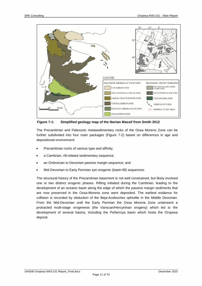
The Oropesa Project is located within the Iberian Massif, a complex orogenic belt consisting of numerous allochthonous and autochthonous terranes that comprise Paleozoic sedimentary sequences with lesser Precambrian basement. These rocks are cut by numerous intrusions of varying ages and deformed by one or more phases of folding and faulting. The Iberian Massif can be subdivided into six zones, based on differences in stratigraphy and structural history (Figure 7-1). The Oropesa project occurs near the northeastern edge of the Ossa Morena Zone.
SRK Consulting Oropesa NI43-101 – Main Report
UK6540 Oropesa NI43-101 Report_Final.docx December 2015 Page 11 of 70
Figure 7-1: Simplified geology map of the Iberian Massif from Smith 2012
The Precambrian and Paleozoic metasedimentary rocks of the Ossa Moreno Zone can be further subdivided into four main packages (Figure 7-2) based on differences in age and depositional environment:
• Precambrian rocks of various type and affinity;
• a Cambrian, rift-related sedimentary sequence;
• an Ordovician to Devonian passive margin sequence; and
• Mid-Devonian to Early Permian syn-orogenic (basin-fill) sequences.
The structural history of the Precambrian basement is not well constrained, but likely involved one or two distinct orogenic phases. Rifting initiated during the Cambrian, leading to the development of an oceanic basin along the edge of which the passive margin sediments that are now preserved in the Ossa-Morena zone were deposited. The earliest evidence for collision is recorded by obduction of the Beja-Acebuches ophiolite in the Middle Devonian. From the Mid-Devonian until the Early Permian the Ossa Morena Zone underwent a protracted multi-stage orogenesis (the Variscan/Hercyninan orogeny) which led to the development of several basins, including the Peñarroya basin which hosts the Oropesa deposit.
SRK Consulting Oropesa NI43-101 – Main Report
UK6540 Oropesa NI43-101 Report_Final.docx December 2015 Page 12 of 70
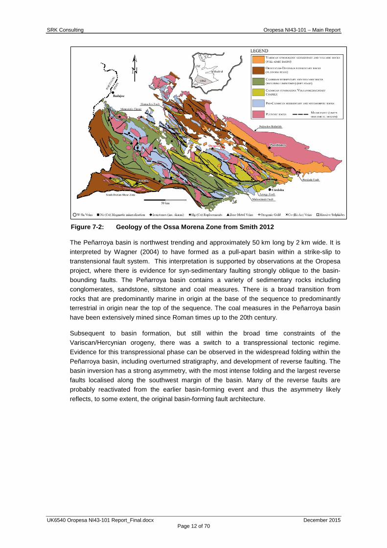
Figure 7-2: Geology of the Ossa Morena Zone from Smith 2012
The Peñarroya basin is northwest trending and approximately 50 km long by 2 km wide. It is interpreted by Wagner (2004) to have formed as a pull-apart basin within a strike-slip to transtensional fault system. This interpretation is supported by observations at the Oropesa project, where there is evidence for syn-sedimentary faulting strongly oblique to the basin-bounding faults. The Peñarroya basin contains a variety of sedimentary rocks including conglomerates, sandstone, siltstone and coal measures. There is a broad transition from rocks that are predominantly marine in origin at the base of the sequence to predominantly terrestrial in origin near the top of the sequence. The coal measures in the Peñarroya basin have been extensively mined since Roman times up to the 20th century.
Subsequent to basin formation, but still within the broad time constraints of the Variscan/Hercynian orogeny, there was a switch to a transpressional tectonic regime. Evidence for this transpressional phase can be observed in the widespread folding within the Peñarroya basin, including overturned stratigraphy, and development of reverse faulting. The basin inversion has a strong asymmetry, with the most intense folding and the largest reverse faults localised along the southwest margin of the basin. Many of the reverse faults are probably reactivated from the earlier basin-forming event and thus the asymmetry likely reflects, to some extent, the original basin-forming fault architecture.

SRK Consulting Oropesa NI43-101 – Main Report
UK6540 Oropesa NI43-101 Report_Final.docx December 2015 Page 13 of 70
Figure 7-3: Schematic cross section illustrating the evolution of folding in the
Peñarroya basin modified from Wagner 2004
7.2 Local/Project Geology
7.2.1 Stratigraphy
The Oropesa Deposit consists of two main lithological units: conglomerate and sandstone.
The conglomerate is poorly-sorted and predominantly clast-supported (Figure 7-4). It consists primarily of cobble to pebble-sized, sub rounded clasts with a gradational matrix. Most clasts are of sedimentary origin, although occasional igneous clasts can be observed. Locally, the conglomerate also contains occasional 1-5 m interbeds of sandstone.
Figure 7-4: Conglomerate intersected in drillhole ORPD57 at 193.8 m
The sandstone unit is quite variable and includes several different lithofacies. There is considerable grain size variation, from a pebbly sandstone, down to a very fine sandstone; however, the majority of the sandstones fall between the fine and granule grain size classifications (Figure 7-5).
SRK Consulting Oropesa NI43-101 – Main Report
UK6540 Oropesa NI43-101 Report_Final.docx December 2015 Page 14 of 70
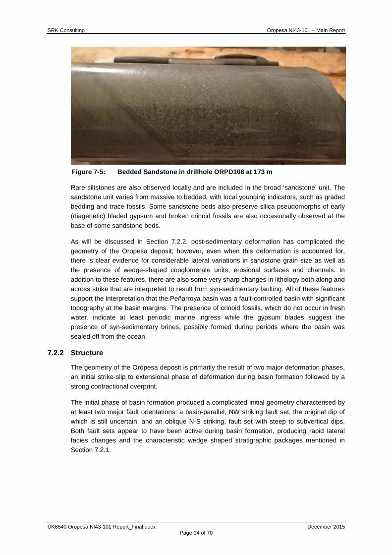
Figure 7-5: Bedded Sandstone in drillhole ORPD108 at 173 m
Rare siltstones are also observed locally and are included in the broad ‘sandstone’ unit. The sandstone unit varies from massive to bedded, with local younging indicators, such as graded bedding and trace fossils. Some sandstone beds also preserve silica pseudomorphs of early (diagenetic) bladed gypsum and broken crinoid fossils are also occasionally observed at the base of some sandstone beds.
As will be discussed in Section 7.2.2, post-sedimentary deformation has complicated the geometry of the Oropesa deposit; however, even when this deformation is accounted for, there is clear evidence for considerable lateral variations in sandstone grain size as well as the presence of wedge-shaped conglomerate units, erosional surfaces and channels. In addition to these features, there are also some very sharp changes in lithology both along and across strike that are interpreted to result from syn-sedimentary faulting. All of these features support the interpretation that the Peñarroya basin was a fault-controlled basin with significant topography at the basin margins. The presence of crinoid fossils, which do not occur in fresh water, indicate at least periodic marine ingress while the gypsum blades suggest the presence of syn-sedimentary brines, possibly formed during periods where the basin was sealed off from the ocean.
7.2.2 Structure
The geometry of the Oropesa deposit is primarily the result of two major deformation phases, an initial strike-slip to extensional phase of deformation during basin formation followed by a strong contractional overprint.
The initial phase of basin formation produced a complicated initial geometry characterised by at least two major fault orientations: a basin-parallel, NW striking fault set, the original dip of which is still uncertain, and an oblique N-S striking, fault set with steep to subvertical dips. Both fault sets appear to have been active during basin formation, producing rapid lateral facies changes and the characteristic wedge shaped stratigraphic packages mentioned in Section 7.2.1.
SRK Consulting Oropesa NI43-101 – Main Report
UK6540 Oropesa NI43-101 Report_Final.docx December 2015 Page 15 of 70
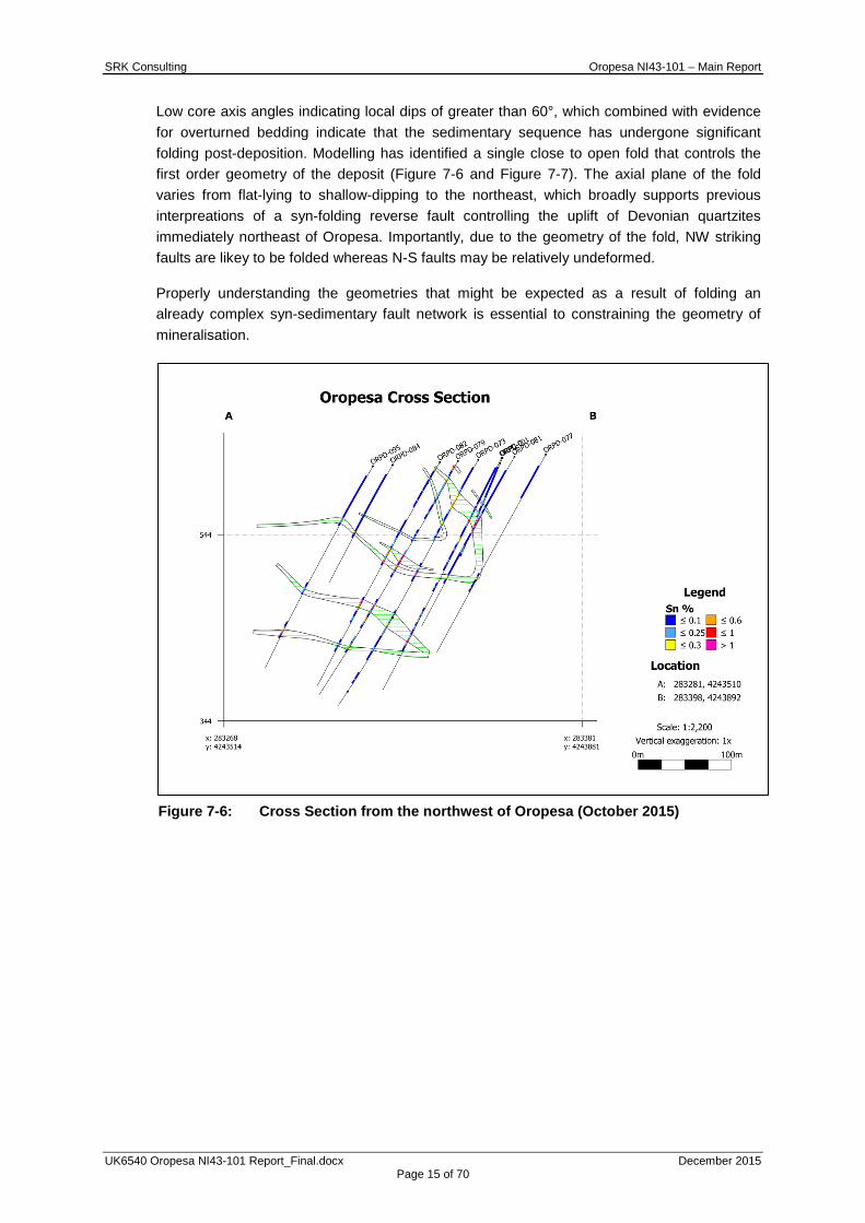
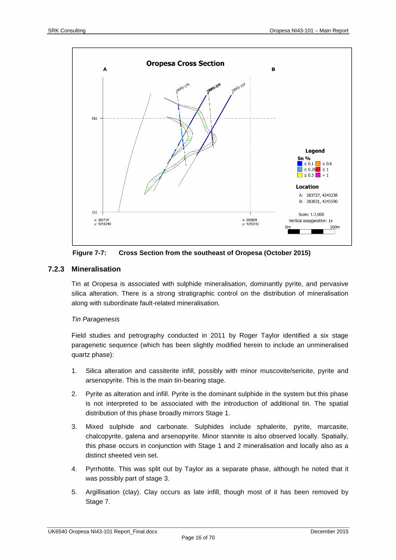
Low core axis angles indicating local dips of greater than 60°, which combined with evidence for overturned bedding indicate that the sedimentary sequence has undergone significant folding post-deposition. Modelling has identified a single close to open fold that controls the first order geometry of the deposit (Figure 7-6 and Figure 7-7). The axial plane of the fold varies from flat-lying to shallow-dipping to the northeast, which broadly supports previous interpreations of a syn-folding reverse fault controlling the uplift of Devonian quartzites immediately northeast of Oropesa. Importantly, due to the geometry of the fold, NW striking faults are likey to be folded whereas N-S faults may be relatively undeformed.
Properly understanding the geometries that might be expected as a result of folding an already complex syn-sedimentary fault network is essential to constraining the geometry of mineralisation.
Figure 7-6: Cross Section from the northwest of Oropesa (October 2015)
SRK Consulting Oropesa NI43-101 – Main Report
UK6540 Oropesa NI43-101 Report_Final.docx December 2015 Page 16 of 70
Figure 7-7: Cross Section from the southeast of Oropesa (October 2015)
7.2.3 Mineralisation
Tin at Oropesa is associated with sulphide mineralisation, dominantly pyrite, and pervasive silica alteration. There is a strong stratigraphic control on the distribution of mineralisation along with subordinate fault-related mineralisation.
Tin Paragenesis
Field studies and petrography conducted in 2011 by Roger Taylor identified a six stage paragenetic sequence (which has been slightly modified herein to include an unmineralised quartz phase):
1. Silica alteration and cassiterite infill, possibly with minor muscovite/sericite, pyrite and arsenopyrite. This is the main tin-bearing stage.
2. Pyrite as alteration and infill. Pyrite is the dominant sulphide in the system but this phase is not interpreted to be associated with the introduction of additional tin. The spatial distribution of this phase broadly mirrors Stage 1.
3. Mixed sulphide and carbonate. Sulphides include sphalerite, pyrite, marcasite, chalcopyrite, galena and arsenopyrite. Minor stannite is also observed locally. Spatially, this phase occurs in conjunction with Stage 1 and 2 mineralisation and locally also as a distinct sheeted vein set.
4. Pyrrhotite. This was split out by Taylor as a separate phase, although he noted that it was possibly part of stage 3.
5. Argillisation (clay). Clay occurs as late infill, though most of it has been removed by Stage 7.
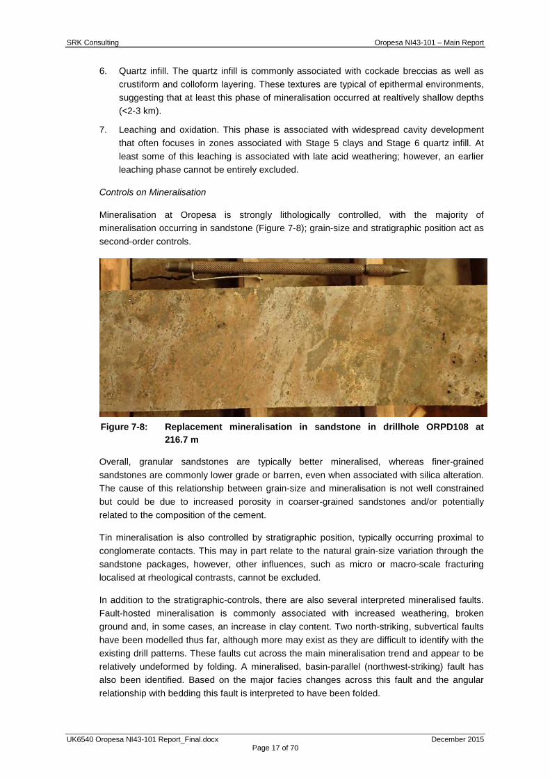
SRK Consulting Oropesa NI43-101 – Main Report
UK6540 Oropesa NI43-101 Report_Final.docx December 2015 Page 17 of 70
6. Quartz infill. The quartz infill is commonly associated with cockade breccias as well as crustiform and colloform layering. These textures are typical of epithermal environments, suggesting that at least this phase of mineralisation occurred at realtively shallow depths (<2-3 km).
7. Leaching and oxidation. This phase is associated with widespread cavity development that often focuses in zones associated with Stage 5 clays and Stage 6 quartz infill. At least some of this leaching is associated with late acid weathering; however, an earlier leaching phase cannot be entirely excluded.
Controls on Mineralisation
Mineralisation at Oropesa is strongly lithologically controlled, with the majority of mineralisation occurring in sandstone (Figure 7-8); grain-size and stratigraphic position act as second-order controls.
Figure 7-8: Replacement mineralisation in sandstone in drillhole ORPD108 at
216.7 m
Overall, granular sandstones are typically better mineralised, whereas finer-grained sandstones are commonly lower grade or barren, even when associated with silica alteration. The cause of this relationship between grain-size and mineralisation is not well constrained but could be due to increased porosity in coarser-grained sandstones and/or potentially related to the composition of the cement.
Tin mineralisation is also controlled by stratigraphic position, typically occurring proximal to conglomerate contacts. This may in part relate to the natural grain-size variation through the sandstone packages, however, other influences, such as micro or macro-scale fracturing localised at rheological contrasts, cannot be excluded.
In addition to the stratigraphic-controls, there are also several interpreted mineralised faults. Fault-hosted mineralisation is commonly associated with increased weathering, broken ground and, in some cases, an increase in clay content. Two north-striking, subvertical faults have been modelled thus far, although more may exist as they are difficult to identify with the existing drill patterns. These faults cut across the main mineralisation trend and appear to be relatively undeformed by folding. A mineralised, basin-parallel (northwest-striking) fault has also been identified. Based on the major facies changes across this fault and the angular relationship with bedding this fault is interpreted to have been folded.

SRK Consulting Oropesa NI43-101 – Main Report
UK6540 Oropesa NI43-101 Report_Final.docx December 2015 Page 18 of 70
Fault-hosted mineralisation is volumetrically much less significant than the replacement style mineralisation, however, they are interpreted to have acted as feeder structures, bringing the mineralising fluid up from depth.
A sheeted carbonate-base metal vein system is also locally observed at Oropesa. Where present, these veins are typically 1cm wide, with a spacing of 1-5m and a sulphide mineralogy dominated by chalcopyrite, sphalerite and galena. This vein system is interpreted to be associated with Stage 3 in the paragenetic sequence and thus likely post-dates the major tin mineralising stage.
Timing of Mineralisation
Mineralisation occurred during the Variscan/Hercynian orogeny. Initial indications suggest that mineralisation was pre-folding, however, further field studies focused on identifying key timing relationships and testing existing concepts will need to be completed to improve the associated geological understanding as this will be an important constraint for planning the next phase of exploration.
8 DEPOSIT TYPES The Oropesa deposit is a replacement type deposit with subordinate fault-controlled mineralisation. It likely formed at formed at relatively shallow depths (<5 km) and potentially well above the granitic intrusion that was the likely source for the mineralising fluid. Pyroxene-rich skarn does occur locally at Oropesa (Taylor 2011), however, skarn accounts for only a very small proportion of the deposit in terms of volume and has an inconsistent relationship with mineralisation (typically <0.25% Sn), suggesting that Oropesa is not primarily a skarn deposit. Instead, it has more in common with the Tasmanian replacement deposits such as Renison Bell, Cleveland and Mt Bischoff. As with Oropesa, each of these has significant massive to semi-massive sulphide mineralisation and varying degrees of silica alteration. They differ from Oropesa in that they are all hosted in carbonate host rocks, however, this difference could be explained if the granular sandstones at Oropesa originally contained a carbonate cement. It should be noted that tin deposits have not been a major focus of academic research over the last 30 years. Therefore the classification of some modern tin deposits can be somewhat difficult as these classification systems do not necessarily represent the full diversity of styles that may exist in nature.
9 EXPLORATION 9.1 Historical Exploration
Instituto Geológico y Minero de España (“IGME”), between 1969 and late 1990, conducted multi-discipline exploration programmes over an area which included the current Oropesa property. These programmes included 1:50,000 scale geological mapping, and stream sediment geochemical surveys. The mapping programme discovered the presence of tin (Sn) on the present Oropesa property in 1982. The tin mineralisation on Oropesa was identified as banded copper-tin veins occurring within a carbonitised detrital unit of Lower Carboniferous age.

SRK Consulting Oropesa NI43-101 – Main Report
UK6540 Oropesa NI43-101 Report_Final.docx December 2015 Page 19 of 70
From 1983 to 1990, exploration on the property was focused on two areas of tin mineralisation, Oropesa and La Grana (situated approximately 1.5 km north of Oropesa) and also covered the regional extents of the property. The exploration programmes conducted during this time included, detailed mapping, geochemical surveys (including stream sediment and soil), and geophysical surveys (including ground Induced Polarization and Resistivity, ground and airborne magnetic and VLF electromagnetic surveys), trenching, diamond drilling and metallurgical test work.
9.1.1 Regional Geological Mapping
From 1982 to 1988, detailed geological mapping was completed over the property and surrounding areas. The tin mineralisation host unit was identified as a carbonitised, detrital conglomerate and arenite (also referred to as greywacke) and this was traced across the property.
9.1.2 Regional Geochemical Stream Sediment Surveys
Multiple stream sediment sampling programmes have been undertaken over Oropesa and the surrounding areas. Approximately 130 samples covering 115 km2 were taken and analysed for Cu, Pb, Zn, and Sn. No sample collection or analytical methodology is available. As expected, the best Sn values (<10 to 650 ppm) were situated over the Oropesa area. Higher Cu, Pb and Zn values were found not to correlate with the higher Sn values.
Additional sampling from the same area included 36 samples which were concentrated by panning, followed by heavy liquid separation and, subsequently, a Frantz magnetic separator. Information from the sampling programmes is incomplete, with only limited descriptive information available for 20 of the 36 samples. Mineralogical content was examined by Dr D Antonio Arribas from the Granada University. Cassiterite was identified in 18 samples, with samples from downstream of the Oropesa project showing most abundant cassiterite concentrations. Figure 9-1 shows a map of the results from the stream sediment sampling program.
SRK Consulting Oropesa NI43-101 – Main Report
UK6540 Oropesa NI43-101 Report_Final.docx December 2015 Page 20 of 70
Figure 9-1: Map of Oropesa Stream Sediment Sampling Results (Source: MESPA)
9.1.3 Regional Geochemical Soil Surveys
A regional geochemical soil survey was conducted by IGME in 1989 and covered both Oropesa (11 lines, 1200 m long, 100 m apart, oriented at 030°) and La Grana (two lines, approximately 500 m long, 100 m apart, oriented at 030°). The aim of the survey was to establish the ideal parameters (grain size, minimum sample density, soil horizon) for a regional sampling programme and the Oropesa project area was used as a control site. Samples were collected from the B soil horizon (where outcrops occurred surface soil was collected) and 575 samples in total were collected at -80 mesh (-0.177 mm) and sent for analysis.
Twenty-three test pits were also dug between 1.5 and 2 m deep using an excavator. Soil horizons A, B, and C were sampled for 69 samples and three fractions were collected (0.25/+0.177 mm, -0.177/+0.125 mm, and <0.125 mm). Analysis was completed by ICP methodology for 20 elements and colorimetry for three elements: Sn, tungsten (W), and fluorine (F).
Results indicated that A-B soil material at -80 mesh is suitable for analysis, at a sampling density of 100x250 m. Sampling identified areas of Sn mineralisation and hydrothermal alteration zones.
SRK Consulting Oropesa NI43-101 – Main Report
UK6540 Oropesa NI43-101 Report_Final.docx December 2015 Page 21 of 70
9.1.4 Regional Geophysical Surveys
Combined Airborne Magnetic, Electromagnetic and VLF Survey
An area covering approximately 160 km2 (including the entire Oropesa property) was flown by helicopter between December 1987 and January 1988 by Aerodat Ltd. Lines were flown at approximately 400 m spacing (although 200 m intervals occurred in places) on a bearing of 030º, with an average ground clearance of 60 m. A magnetic high (2000 m long and 1000 m wide) was identified which is associated with the Sierra La Grana – Oropesa area. The Oropesa project appears to coincide with an electro-magnetic anomaly, whilst a second anomaly extends westward from the La Grana occurrences.
9.1.5 Local Geochemical Soil Surveys
Soil Surveys
Soil surveys at Oropesa were undertaken from 1989 to 1990 and included 25 lines, approximately 100 m apart at an orientation of 020º. Samples were taken at 25 m spacing, and the lines varied from 500 to 1300 m in length. In total, 665 samples were collected and analysed for Sn, Cu, Pb, and Zn at Laboratorios Almeria, SA (“Laboral”) by Atomic Absorption methods. It is unknown whether the laboratory was certified during this time. An anomalous (>125 ppm) area was identified at 2000 m long and 200 – 700 m wide at an approximate orientation of NNW/SSE (Figure 9-2). Three other areas of high Sn were detected in the western, central and southern parts of the area.
At La Grana, 1,173 samples were collected at 25 m spacing and analysed for Cu, Pb, Zn, and Sn. Two areas of significant Sn (>250 ppm) were identified approximately 1.3 km apart (Figure 9-3). Sn occurrences at La Grana West showed a strong correlation with Cu and Pb, whilst La Grana East had a weak Cu-Sn correlation and strong Pb-Sn correlation.
Oropesa IP-Resistivity Survey
A two phase pole-dipole survey was completed over Oropesa in 1983 and 1985. A total of 10.075 km was surveyed and there appeared to be a correlation between chargeability and geochemical anomalies.
Oropesa VLF Electromagnetic and Magnetometer Surveys
A total of 14.775 km of surveys, was conducted across the mineralised horizon at Oropesa, including the three anomalous zones identified by geochemical sampling. Readings were taken parallel to the geochemical grid lines at 25 m intervals, approximately 100 m apart. Data were smoothed using a moving average. Four VLF electromagnetic conductors were identified; being associated with the known mineralisation and geochemical anomalies previously identified with the fourth conductor thought to be due to a result of cultural influences. The magnetic data was found to be inconclusive.
La Grana Gravity Survey
At La Grana, an area of approximately 3x6 km was surveyed on lines spaced either 500 or 1,000 m apart and oriented 020°. Plans of the Bouger, Regional and Residual data is available; however, no report has been found to date. Separate gravity anomalies are coincident with both the La Grana West and La Grana East occurrences.

SRK Consulting Oropesa NI43-101 – Main Report
UK6540 Oropesa NI43-101 Report_Final.docx December 2015 Page 22 of 70
Figure 9-2: Schematic of the Oropesa soil geochemistry relative to wireframe
locations and interpreted faults (Source: MESPA)
Figure 9-3: Schematic of the La Grana West and La Grana East soil geochemistry
and interpreted faults (Source: MESPA)

SRK Consulting Oropesa NI43-101 – Main Report
UK6540 Oropesa NI43-101 Report_Final.docx December 2015 Page 23 of 70
9.1.6 Oropesa Trenching and Sampling
From 1982 through to 1986, 26 trenches totalling 2,681 m in cumulative length were dug to bed rock. The trenches were oriented at 020° and at a maximum approximate depth of 3 m. Nine of the trenches were aimed at exposing mineralisation and 14 were designed to test geochemical and geophysical anomalies. All of trenches were mapped in detail; however systematic sampling occurred only for the last 14 trenches. Sample methodology was not typically detailed. All analysis was completed at the IGME laboratory in Madrid by XRF.
9.1.7 Local Drilling
Between 1983 and 1990, 33 holes were drilled by IGME in to the Oropesa anomaly. Further details are provided in Section 10.1.
9.1.8 Mineralogical Studies
Mineralogical studies were undertaken by IGME and reported in the Boletin Geologico y Minero (Alverez Rodriguez and Gomez-Limon, 1988, and Garcia Frutos and Ranz Boquerin, 1989). Both papers describe technical difficulties encountered in relation to the recovery of cassiterite from Oropesa with poor yields being a result of a low liberation size and the occurrence of iron oxides which are partly embedded in the cassiterite.
9.2 Exploration by the Company
Since acquisition of the property, the Company has completed a review of the IGME data including re-interpretation and development of an exploration model for tin emplacement. A number of exploration programmes have been carried out over the property including geochemical and geophysical surveys, trenching, test pitting programmes.
9.2.1 Geochemical Survey
From 2008 to 2010, a sampling programme was conducted taking 160 float samples from the La Grana West area (a small number of samples were also taken from La Grana East and Oropesa). All sample locations were recorded using a hand held GPS (±5 m accuracy).
The aim of this sampling programme was to identify and prove the presence of cassiterite mineralisation on the property, and to gain an understanding of the size and nature of the mineralisation.
Samples were approximately cobble sized and were initially collected randomly over areas of 1.5x1.0 km area at Oropesa, 1.0x1.0 km area at La Grana West and 0.5x0.75 km area at La Grana East. Once the presence and orientation of the mineralisation had been identified, samples were collected in a manner which would confirm mineralisation orientation. All samples were described geologically and subsequently bagged and tagged.
9.2.2 Geophysical Surveys
From February to June 2011, IP-resistivity and ground magnetic surveys were conducted over the property. The IP-resistivity survey covered 50.02 line km on 34 lines spaced 50 to 100 m apart and oriented NE/SW. A dipole-dipole electrode array was used, spacing between electrodes was 20 m and the distance between the current dipole and receiving potential dipole was between 1 and 20 m. The Oropesa mineralisation corresponded with anomalies identified in the central part of the survey area. A number of sub-parallel NNW/SSE anomalies were identified by the survey.

SRK Consulting Oropesa NI43-101 – Main Report
UK6540 Oropesa NI43-101 Report_Final.docx December 2015 Page 24 of 70
The magenetic survey covered 63.5 km along the IP NE/SW oriented IP lines. An additional six lines plus three tie lines were also surveyed. Readings were taken automatically every two seconds, as the operator walked along the lines, GPS readings were also taken at each location. A general NW/SE trend is visible, with the Oropesa mineralisation lying at a change in magnetics between the shale (highly magnetic) to the SW and conglomerate (low magnetic) to the NW.
Additionally, detailed airborne Versatile Time Domain Electromagnetic (“VTEM”) and magnetic surveys were undertaken in 2011 and SRK Exploration Services Ltd carried out the processing and interpretation of the data. The VTEM survey was performed by Geotech in 2011 and covered most of the area with lines flown in a NNE direction with a central area covering the Oropesa project flown in more detail in the orthogonal ESE direction. It was found that the Oropesa Sn deposit gave rise to a strong electromagnetic anomaly that indicates the presence of good conductivity material at depth. The conductor appeared to be approximately 1100 m long and 800 m wide and possibly caused by more conductive minerals such as pyrrhotite.
9.2.3 Trenching Programmes
Trenching programmes were undertaken at La Grana West (18 trenches, 8 to 30 m in length, totalling a cumulative length of 720 m) and La Grana East (one trench, 284 m in length). Trenches were oriented across areas of known mineralisation with the purpose of exposing bedrock and determining whether high grade intercepts indicated mineralized structures. Some areas of high Sn concentrations were found, however these were sporadic in nature. The company believes some mineralized areas are due to soil creep (Burns, 2011).
9.2.4 Test Pitting Programmes
In early 2011, the Arroyo Majavacas flood plain located in the southeast of the property was sampled using nine test pits. The aim was to test the potential for alluvial Sn deposits. The test pits were dug (using an excavator) down to bedrock at depths of between 1.7 to 2.7 m.
Material between the overlying soil and underlying rock was sampled, assay results ranged from 6 to 219 ppm Sn, with only two out of 12 assays above 100 ppm Sn. These results indicate the presence of an alluvial Sn deposit on the flood plain being unlikely.
10 DRILLING 10.1 Historical Drilling
Between 1983 and 1990, 33 core drillholes with a cumulative length of 6,913.55 m were drilled by IGME in to the Oropesa anomaly. The majority of these holes were oriented at 020° NE. Between 1987 and 1990, 16 core drillholes with a cumulative length of 3,420 m were drilled in to the neighbouring La Grana Sn occurrences. Holes one to five tested La Grana West, and Holes six to 16 La Grana East.
SRK Consulting Oropesa NI43-101 – Main Report
UK6540 Oropesa NI43-101 Report_Final.docx December 2015 Page 25 of 70
Holes were collared in HQ and reduced to NQ, and BQ where required. There are no descriptive drill logs available (only graphical logs) and no report has been found detailing the purpose and interpreted results of the drill programme. Collar surveys were not completed and downhole surveys are noted only on the graphical logs (survey method was not recorded). Drill collars were located by Burns during a site visit. Sample lengths vary and Burns (August, 2011) notes that sampling appears to have been primarily based on core recovery. It was also noted that sections of mineralized core had not been sampled.
All sample preparation was undertaken at IGME Litoteca de Sondeos in Penarroya-Pueblonuevo, and all analysis for Cu, Pb, Zn, and Sn by XRF was completed at the IGME laboratory in Madrid.
10.2 Drilling by the Company
The Company has undertaken five drilling programs to date, with the latest phase of drilling and sampling completed between April and May 2015. A summary of each of the drill programs is provided as follows:
10.2.1 Drilling Summary 2010
The first drill programme (March to November, 2010) comprised of 30 holes with a cumulative length of 4,817.10 m, conducted by drill contractor Sondeos y Perforaciones Industrales del Bierzo, SA (SPIB), also the property vendor. Sixteen holes were drilled at Oropesa (totalling 2,798.9 m) and 14 holes at La Grana West (totalling 2,018.2 m). The core was typically HQ in size, although reduction to NQ occurred in two holes. A track mounted, Model 100 SPIRILL hydraulic diamond drill was used; this equipment could reach a maximum depth of 750 m.
As the IGME drillhole collars were difficult to locate, the data was used only to provide an approximate location for the mineralisation. The 16 holes drilled at Oropesa covered an 800 m strike length and were designed to intersect previously drilled mineralisation. This drilling encountered hydrothermal Sn and sulphide mineralisation in the eastern anomaly at Oropesa. The 14 drillholes at La Grana West were exploration holes aimed at testing the various structures which had been identified during sampling programmes and from re-interpretation of the IGME data.
10.2.2 Drilling Summary 2011
The second SPIB Oropesa drill programme (December 2010 to July 2011) completed by the Company, included 92 diamond drillholes with a total cumulative length of 20,023.45 m.
All holes were planned in Datamine Mining Software, and a compass and handheld GPS were used to position the holes. Downhole surveys were taken using a Reflex single shot camera at approximately 50 m intervals. Deviations in azimuth have been attributed to the magnetic minerals (pyrrhotite) present in rocks at Oropesa. The aim of the drill programme was to:
• delineate the grade, and attitude of zones and/or expand zones laterally by using a fence across the mineralized zones;
• test IP delineated targets;
• determine source of high grade Sn boulders located in the SE of the property; and
• check the existence of interpreted structures.
SRK Consulting Oropesa NI43-101 – Main Report
UK6540 Oropesa NI43-101 Report_Final.docx December 2015 Page 26 of 70
On completion of drilling, holes were geotechnically (RQD, core recovery) and geologically logged, all core was photographed and samples were selected and marked. All data is entered electronically.
The November 2011 drilling programme indicated that the mineralisation dips to the north, suggesting that the IGME and previous Eurotin (2010) holes were drilled in the wrong orientation. All subsequent drilling has therefore been drilled to the south.
10.2.3 Drilling Summary 2012
The third drilling phase was completed in May 2012 with the drilling completed by SPIB for an additional 21,233.1 m of diamond core (“DC”) drilling (92 holes) and 2,118.0 m reverse circulation (“RC”) drilling (16 holes), for a total of 108 holes. All drilling undertaken in this phase of work was conducted to infill to a 50x50 m grid with a partial 25x25 m grid.
10.2.4 Drilling Summary 2013
The fourth phase was completed during June to September 2013 for an additional 4,087.8 m. During this phase, a total of 24 holes were drilled across the deposit to target higher grade structures and infill areas of lower confidence.
10.2.5 Drilling Summary 2015
The latest phase of exploration drilling and sampling was a relatively small program aimed at confirming the presence of mineralisation within previously non-sampled zones and testing for additional tin mineralisation at depth below previously modelled domains. DC drillholes for 2015 were collared on previously established drill section lines and angled between -60° and -80° (below horizontal) towards the southwest and northeast.
Additions to the database for 2015 consist of a further three drillholes for 980 m of DC drilling, with an additional four earlier holes for some 754 m which were not available in time for the 2014 MRE drilling database. In addition, some 47 samples from six drillholes have been submitted for analysis from previously non-sampled drill core. The positions of new drillhole collars for 2015 are illustrated in Figure 10-1.
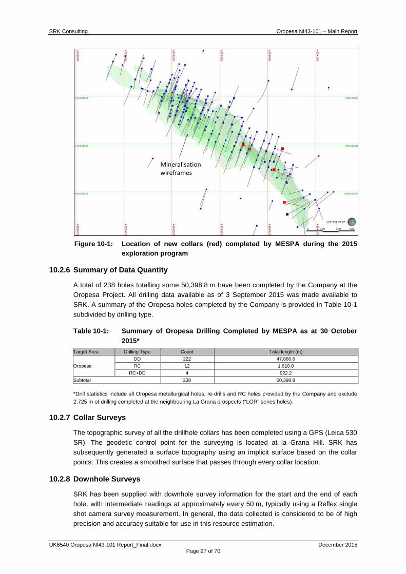
SRK Consulting Oropesa NI43-101 – Main Report
UK6540 Oropesa NI43-101 Report_Final.docx December 2015 Page 27 of 70
Figure 10-1: Location of new collars (red) completed by MESPA during the 2015
exploration program
10.2.6 Summary of Data Quantity
A total of 238 holes totalling some 50,398.8 m have been completed by the Company at the Oropesa Project. All drilling data available as of 3 September 2015 was made available to SRK. A summary of the Oropesa holes completed by the Company is provided in Table 10-1 subdivided by drilling type.
Table 10-1: Summary of Oropesa Drilling Completed by MESPA as at 30 October 2015*
Target Area Drilling Type Count Total length (m)
Oropesa DD 222 47,866.6 RC 12 1,610.0
RC+DD 4 922.2 Subtotal 238 50,398.8
*Drill statistics include all Oropesa metallurgical holes, re-drills and RC holes provided by the Company and exclude 2,725 m of drilling completed at the neighbouring La Grana prospects (“LGR” series holes).
10.2.7 Collar Surveys
The topographic survey of all the drillhole collars has been completed using a GPS (Leica 530 SR). The geodetic control point for the surveying is located at la Grana Hill. SRK has subsequently generated a surface topography using an implicit surface based on the collar points. This creates a smoothed surface that passes through every collar location.
10.2.8 Downhole Surveys
SRK has been supplied with downhole survey information for the start and the end of each hole, with intermediate readings at approximately every 50 m, typically using a Reflex single shot camera survey measurement. In general, the data collected is considered to be of high precision and accuracy suitable for use in this resource estimation.
Mineralisation wireframes
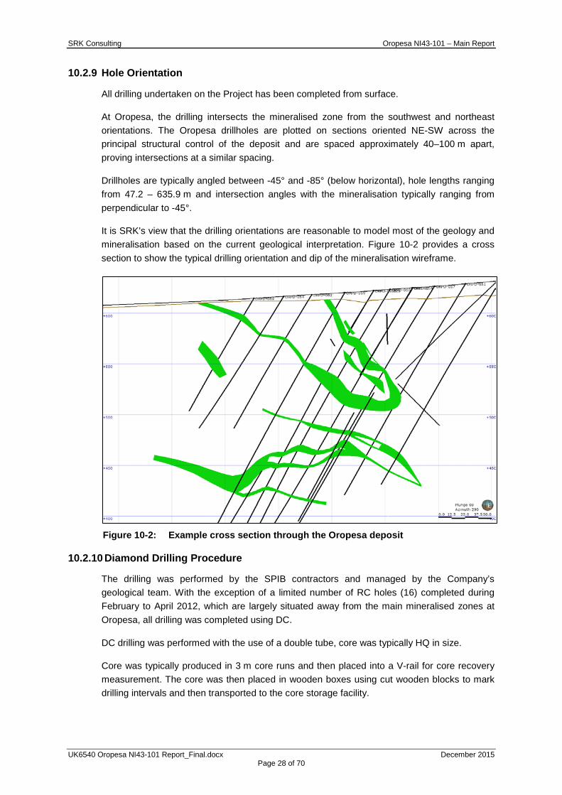
SRK Consulting Oropesa NI43-101 – Main Report
UK6540 Oropesa NI43-101 Report_Final.docx December 2015 Page 28 of 70
10.2.9 Hole Orientation
All drilling undertaken on the Project has been completed from surface.
At Oropesa, the drilling intersects the mineralised zone from the southwest and northeast orientations. The Oropesa drillholes are plotted on sections oriented NE-SW across the principal structural control of the deposit and are spaced approximately 40–100 m apart, proving intersections at a similar spacing.
Drillholes are typically angled between -45° and -85° (below horizontal), hole lengths ranging from 47.2 – 635.9 m and intersection angles with the mineralisation typically ranging from perpendicular to -45°.
It is SRK’s view that the drilling orientations are reasonable to model most of the geology and mineralisation based on the current geological interpretation. Figure 10-2 provides a cross section to show the typical drilling orientation and dip of the mineralisation wireframe.
Figure 10-2: Example cross section through the Oropesa deposit
10.2.10 Diamond Drilling Procedure
The drilling was performed by the SPIB contractors and managed by the Company’s geological team. With the exception of a limited number of RC holes (16) completed during February to April 2012, which are largely situated away from the main mineralised zones at Oropesa, all drilling was completed using DC.
DC drilling was performed with the use of a double tube, core was typically HQ in size.
Core was typically produced in 3 m core runs and then placed into a V-rail for core recovery measurement. The core was then placed in wooden boxes using cut wooden blocks to mark drilling intervals and then transported to the core storage facility.

SRK Consulting Oropesa NI43-101 – Main Report
UK6540 Oropesa NI43-101 Report_Final.docx December 2015 Page 29 of 70
10.2.11 Core Recovery
Sample recovery is measured by technical staff as part of the logging process. This is recorded in the drilling logs.
Visual assessment of the core shows that recovery is variable with areas of lower recoveries often noted in zones of significant oxidation, mineralisation or structure. Estimated recovery ranges from 0% to 100% core recovery and averages 92%.
The core loss in higher grade regions was investigated to test for the existence of a relationship with increased grade and decreased core recovery. Figure 10-3 presents a correlation plot of Sn% grade versus estimated recovery. No clear relationship exists and therefore it is unlikely that a systematic bias has been introduced.
While no systematic relationship exists between Sn grade and recovery, future drilling should consider appropriate techniques to improve areas where problematic drilling conditions are anticipated. For example, triple tube diamond coring or reverse circulation drilling could be considered.
Figure 10-3: Sn% versus core recovery
10.2.12 Core Storage
All diamond drill core is stored in custom made wooden core boxes in the warehouse located in the town of Fuente Obejuna, Cordoba. The boxes are then stacked on pallets. In addition to the core storage, crushed reject samples are returned from ALS Laboratories sample preparation facility in Seville, Spain (“ALS Seville”) and stored in the facility in locked metal containers for later submission as supplicate samples.
The facility is locked and secured. A security system alarm has been installed and is connected to the police station. Access to the sample storage facility is restricted to MESPA personnel.
0
2
4
6
8
10
12
14
16
0 20 40 60 80 100
Sn (%
)
Recovery (%)
SN_PCT versus REC_PCT
SN_PCT versus REC_PCT

SRK Consulting Oropesa NI43-101 – Main Report
UK6540 Oropesa NI43-101 Report_Final.docx December 2015 Page 30 of 70
10.3 SRK Comments
In the opinion of SRK, the sampling procedures used by the Company conform to industry standard practices and the resultant drilling pattern is sufficiently dense to interpret the geometry, geological boundaries and tin mineralisation with an appropriate level of confidence.
11 SAMPLE PREPARATION, ANALYSIS AND SECURITY 11.1 Introduction
The following section relates to the methods and protocols used by the Company during the 2015 exploration campaign, which remains unchanged from the Company’s previous sampling programs.
11.2 Chain of Custody, Sample Preparation, and Analyses
All core samples are collected from the drill rig and transported to the core farm in Fuente Obejuna, Cordoba, by Company personnel for logging, sample selection and splitting using a core saw. The samples are then transported by the Company to the ALS sample preparation facility in Seville (“ALS Seville”) as batches of between approximately 40 to 150 samples. It has been common practise to submit the samples on a hole by hole basis.
The samples received by the ALS Seville sample preparation facility are logged into the LIMS tracking system and processed in accordance to the requested analytical procedure. Sample preparation is via procedure PREP-31 in which the sample is weighed, dried, and crushed prior to a 250 g split being taken and pulverized to better than 85% passing 75 microns. Samples are then shipped by bonded courier to the ALS Laboratory in Vancouver, Canada (“ALS Vancouver”), for analysis by glass fusion X-Ray fluorescence (“XRF”). ALS Seville is ISO accredited.
11.3 Specific Gravity Data
The Company technical staff collected bulk density data using an immersion method collecting weight in air versus weight in water. Density determinations were completed as follows:
• Three pieces of core were selected for each sample interval (1 or 2 m sampling interval depending if the interval was visually mineralized or not).
• The core billets were selected taking into account the lithology and the core quality (competent intervals were selected preferentially).
• Calibration weights were used to check the calibration scale each day prior to weighing samples commenced. The scale was calibrated to ±5 g;
• The core billet was oven dried and weighed prior to immersion to determine the dry weight of the sample (Sample weight A). The core billet was then placed in the sample basket, immersed in water and reweighed to determine the weight in water (Sample weight B). The core was observed to ensure all bubbles disappeared prior to the immersed sample weight was determined.
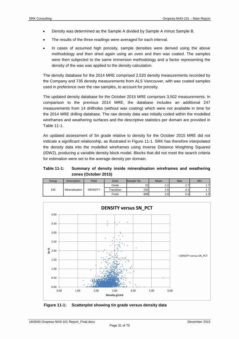
SRK Consulting Oropesa NI43-101 – Main Report
UK6540 Oropesa NI43-101 Report_Final.docx December 2015 Page 31 of 70
• Density was determined as the Sample A divided by Sample A minus Sample B.
• The results of the three readings were averaged for each interval.
• In cases of assumed high porosity, sample densities were derived using the above methodology and then dried again using an oven and then wax coated. The samples were then subjected to the same immersion methodology and a factor representing the density of the wax was applied to the density calculation.
The density database for the 2014 MRE comprised 2,520 density measurements recorded by the Company and 735 density measurements from ALS Vancouver, with wax coated samples used in preference over the raw samples, to account for porosity.
The updated density database for the October 2015 MRE comprises 3,502 measurements. In comparison to the previous 2014 MRE, the database includes an additional 247 measurements from 14 drillholes (without wax coating) which were not available in time for the 2014 MRE drilling database. The raw density data was initially coded within the modelled wireframes and weathering surfaces and the descriptive statistics per domain are provided in Table 11-1.
An updated assessment of Sn grade relative to density for the October 2015 MRE did not indicate a significant relationship, as illustrated in Figure 11-1. SRK has therefore interpolated the density data into the modelled wireframes using Inverse Distance Weighting Squared (IDW2), producing a variable density block model. Blocks that did not meet the search criteria for estimation were set to the average density per domain.
Table 11-1: Summary of density inside mineralisation wireframes and weathering zones (October 2015)
Group Description Field Zone Sample No. Mean Max Min
100 Mineralisation DENSITY Oxide 22 2.2 2.7 1.7
Transition 232 2.5 4.1 1.7 Fresh 808 2.8 5.6 1.3
Figure 11-1: Scatterplot showing tin grade versus density data
0.00
0.50
1.00
1.50
2.00
2.50
3.00
3.50
4.00
0.00 1.00 2.00 3.00 4.00 5.00 6.00
Sn %
Density g/cm3
DENSITY versus SN_PCT
DENSITY versus SN_PCT
SRK Consulting Oropesa NI43-101 – Main Report
UK6540 Oropesa NI43-101 Report_Final.docx December 2015 Page 32 of 70
In the absence of data, an assumed overburden density has been derived from the AusIMM field geologist’s guide, which provides density estimates for various overburden types. The overburden present at the Oropesa deposit is classified and a mix of gravels and clays. From this a dry density of 1.8 g/cm3 has been derived, which remains consistent with the 2014 MRE.
11.4 SRK Comments
In the opinion of SRK, the sampling preparation, security and analytical procedures used by the Company are consistent with generally accepted industry standard practices and are therefore adequate for the purpose of this resource estimate. However, SRK notes that density measurements were only taken using competent core and is therefore likely to overestimate density in zones of broken/rubbly core. Future density test work during any further drill programmes should focus on characterising density in areas of rubbly, oxidised material.
12 DATA VERIFICATION 12.1 Verifications by SRK
In accordance with National Instrument 43-101 guidelines, SRK visited the Project from 20 to 30 July 2015. The main purpose of the site visit was to:
• witness the extent of the exploration work completed to date, discuss the procedures used and verify the locations of selected collars;
• review drill cores for selected holes to confirm both geological and assay values stored in the database;
• discuss updated geological and structural interpretations and inspect drill core; and
• inspect core logging and sample storage facilities.
12.1.1 Verification of Sampling Database
SRK completed a phase of data validation on the digital sample database supplied by the Company which included, but was not limited to the following:
• Search for sample overlaps, duplicate or absent samples, anomalous assay and survey results. No material issues were noted in the final sample database.
• SRK excluded the following historic drillholes that did not pass all aspects of SRK’s validation procedures:
o RC drillhole ORC-10, based on anomalous assay data; and
o 30 historic IGME drillholes, namely the “Oropesa” series holes and ORM-3, ORM-4 and ORM 5 based on low confidence in the survey and assay data. That said, historic drillholes ORM-1 and ORM-2 were not excluded from the database given that the Company has verified these collar locations and the associated tin grade and mineralised thickness visually correlates well adjacent more recent drilling.

SRK Consulting Oropesa NI43-101 – Main Report
UK6540 Oropesa NI43-101 Report_Final.docx December 2015 Page 33 of 70
• Search for absent tin values within the mineralised zones. Excluding non-sampled metallurgical holes, SRK noted the presence of a limited number of absent sample intervals (some 2% of the sample database), which typically relate to core loss in less competent rock or minor volumetric wireframe discrepancy where complexity of the geometry of the mineralisation results in the capture of a few isolated non-sampled intercepts. SRK has treated these absent values on a case by case basis and where sufficiently supported by surrounding mineralised samples, adjacent drilling, or Niton XRF data, ignored the core loss data during the composite process.
12.2 Verifications by the Company
The Company has undertaken validation of sample assays during the exploration drilling programs completed using standards, blanks and duplicate samples (QAQC samples) which have been inserted routinely into each batch submitted to the laboratory at ALS Vancouver.
SRK notes that 2,533 m (72%) of the total 3,527 m of sampling inside mineralisation wireframes is supported by QAQC data, which largely relates to holes drilled following ORPD059 which was drilled during 2011.
The remaining 994 m (28%) of sampling inside the mineralisation wireframes is not supported by QAQC data, however forms part of the same mineralised body and underwent the same sample preparation and assay procedures at ALS Vancouver. These drillholes are interspersed with those that are supported by QAQC data, they are visually comparable with adjacent intersections with QAQC and also show comparable sample distributions and mean grades (Figure 12-1).
Figure 12-1: Composite sample grade log histogram distributions for tin, showing data assayed with QAQC support (left) and without QAQC (right)
The quality assurance and quality control (QAQC) results for tin analysis completed by the Company between 2010-2013 is summarised in Section 12.3 (with more details presented in the NI43-101 PEA report by SRK, dated 30 July 2014), and the QAQC results related to the latest phase of exploration completed during 2015 presented in Section 12.4.
Additional verification and validation work completed by the Company during the latest phase of exploration included:
• a systematic program of Niton XRF analysis and subsequent sampling of previously non-sampled drillcore within zones of interest;
• re-logging the existing core to improve the definition of weathering zones within the geological model.

SRK Consulting Oropesa NI43-101 – Main Report
UK6540 Oropesa NI43-101 Report_Final.docx December 2015 Page 34 of 70
12.3 QAQC for Tin Analysis 2010-2013
Routine QAQC procedures were introduced during the 2011 drilling program following drillhole ORPD059, with a resultant 2,420 m (71%) of the total 3,414 m of drilling (captured inside mineralisation wireframes and completed between 2010 and 2013) supported by QAQC data.
A routine quality assurance quality control (“QAQC”) program was implemented by the Company to monitor the on-going quality of the analytical database. The QAQC system included the submission of blank samples, standards and duplicates in every batch of samples in a proportional sequence every 10-15 samples.
12.3.1 Insertion of CRM
The Company sourced three certified standards (CRM) from African Mineral Standards. The certified standards represent a low, medium and higher grade range. A total of 162 standards were submitted for analysis. The African Mineral Standards used by the Company are summarised in Table 12-1.
Table 12-1: Summary of Certified Reference Material for tin submitted by the Company in sample submissions (2011-2014)
Standard Material Tin; Sn (%)
Certified Value SD Company AMIS0019 1.095 0.062 African Mineral Standards AMIS0020 0.68 0.040 African Mineral Standards AMIS0021 0.27 0.026 African Mineral Standards
A total of 162 standards were available for review representing an insertion rate (relative to the total database of assay samples) of 1 in 83. When compared to the sample database generated subsequent to ORPD059 where systematic QAQC sample insertion was undertaken, the insertion rate improves to 1 in 44.
A review of the available assay data indicates that an acceptable level of accuracy was achieved. All assays were within acceptable tolerance and little overall relative bias is noted. No trends were evident in the data set. Review of the internal quality control at ALS Vancouver using high grade standard MP-1B (expected value 1.61% Sn) provides further support for an acceptable level of accuracy the assay laboratory. CRM charts are presented in Appendix A.
12.3.2 Blanks
A total of 187 blank samples were sourced from a quartz gravel quarry located more than 25 km from the project.
A total of 186 blanks were submitted by the Company to ALS Vancouver for assaying for Sn representing an insertion rate of 1 in 71. When compared to the sample database generated subsequent to ORPD059 where systematic QAQC sample insertion was undertaken, the insertion rate improves to 1 in 38. All except 7 blanks returned less than detection results, as shown in Appendix A, indicating no apparent contamination. The size of the available data set is, however, considered relatively small.
The internal blank samples assayed for Sn and completed by ALS Vancouver (shown in Appendix A sorted by batch) suggest no indication of sample contamination is evident with all sampling noted at below the detection limit.
SRK Consulting Oropesa NI43-101 – Main Report
UK6540 Oropesa NI43-101 Report_Final.docx December 2015 Page 35 of 70
12.3.3 Duplicates
A limited number of duplicate data (166 samples) was available for available, representing coarse reject samples resubmitted to ALS Vancouver for re-assay. This equates to an insertion rate of 1 in 81. When compared to the sample database generated subsequent to ORPD059 where systematic QAQC sample insertion was undertaken, the insertion rate improves to 1 in 43. It is of note that the duplicates are generally assayed in different batches and therefore cannot be considered fully representative of the relative precision of the sample preparation and assaying.
The duplicate data is presented in Appendix A. A high level of correlation is noted between these duplicate data with the linear correlation coefficient being 0.98. Whilst the data set is relatively limited and submission of a substantial set of duplicate samples is recommended, no apparent issues are identified in the duplicate samples.
12.3.4 Umpire Laboratory Duplicates
A small number of inter-laboratory check samples (512) were submitted to SGS Wheal Jane; however, only 61 of these samples are associated with sample numbers that can be correlated with the original assays.
The duplicate data is presented in Appendix A. The duplicate data shows a high level of correlation with the linear correlation coefficient being 0.93.
The data contains a number of anomalous outliers. In SRK’s opinion, it is likely that a degree of variability between duplicate pairs is associated with the inherent variability of the sample or settling and homogenisation issues relating to sample storage and resubmission. While the data set is limited and submission of continuous inter-laboratory duplicate samples is recommended, no major issues are identified in the duplicate samples.
12.4 QAQC for Tin Analysis 2015
All drilling captured inside mineralisation wireframes and completed during 2015 (112 m) is supported by QAQC data.
The following control measures were implemented by the Company to monitor both the precision and accuracy of sampling, preparation and assaying. Results shown have been limited to the QAQC samples inserted during routine 2015 sample submissions.
Certified Reference Materials (“CRM”), blanks and duplicates were submitted into the sample stream, equating to a QAQC sample insertion rate of approximately 8%, as illustrated in Table 12-2. The QAQC system includes the submission of blank samples, CRM and duplicates in every batch of samples in a proportional sequence approximately every 10-15 samples.
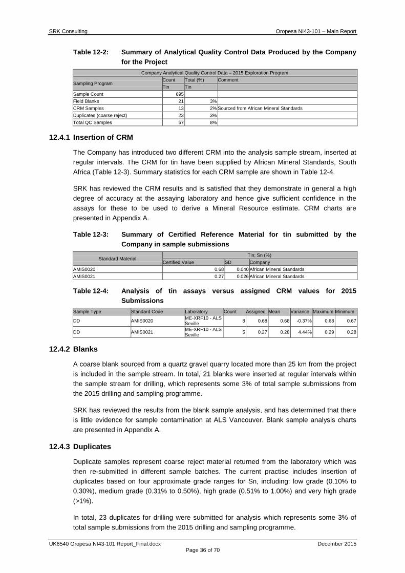
SRK Consulting Oropesa NI43-101 – Main Report
UK6540 Oropesa NI43-101 Report_Final.docx December 2015 Page 36 of 70
Table 12-2: Summary of Analytical Quality Control Data Produced by the Company for the Project
Company Analytical Quality Control Data – 2015 Exploration Program
Sampling Program Count Total (%) Comment Tin Tin
Sample Count 695 Field Blanks 21 3% CRM Samples 13 2% Sourced from African Mineral Standards Duplicates (coarse reject) 23 3% Total QC Samples 57 8%
12.4.1 Insertion of CRM
The Company has introduced two different CRM into the analysis sample stream, inserted at regular intervals. The CRM for tin have been supplied by African Mineral Standards, South Africa (Table 12-3). Summary statistics for each CRM sample are shown in Table 12-4.
SRK has reviewed the CRM results and is satisfied that they demonstrate in general a high degree of accuracy at the assaying laboratory and hence give sufficient confidence in the assays for these to be used to derive a Mineral Resource estimate. CRM charts are presented in Appendix A.
Table 12-3: Summary of Certified Reference Material for tin submitted by the Company in sample submissions
Standard Material Tin; Sn (%)
Certified Value SD Company AMIS0020 0.68 0.040 African Mineral Standards AMIS0021 0.27 0.026 African Mineral Standards
Table 12-4: Analysis of tin assays versus assigned CRM values for 2015 Submissions
Sample Type Standard Code Laboratory Count Assigned Mean Variance Maximum Minimum
DD AMIS0020 ME-XRF10 - ALS Seville 8 0.68 0.68 -0.37% 0.68 0.67
DD AMIS0021 ME-XRF10 - ALS Seville 5 0.27 0.28 4.44% 0.29 0.28
12.4.2 Blanks
A coarse blank sourced from a quartz gravel quarry located more than 25 km from the project is included in the sample stream. In total, 21 blanks were inserted at regular intervals within the sample stream for drilling, which represents some 3% of total sample submissions from the 2015 drilling and sampling programme.
SRK has reviewed the results from the blank sample analysis, and has determined that there is little evidence for sample contamination at ALS Vancouver. Blank sample analysis charts are presented in Appendix A.
12.4.3 Duplicates
Duplicate samples represent coarse reject material returned from the laboratory which was then re-submitted in different sample batches. The current practise includes insertion of duplicates based on four approximate grade ranges for Sn, including: low grade (0.10% to 0.30%), medium grade (0.31% to 0.50%), high grade (0.51% to 1.00%) and very high grade (>1%).
In total, 23 duplicates for drilling were submitted for analysis which represents some 3% of total sample submissions from the 2015 drilling and sampling programme.

SRK Consulting Oropesa NI43-101 – Main Report
UK6540 Oropesa NI43-101 Report_Final.docx December 2015 Page 37 of 70
The duplicates for drilling show a relatively good correlation to the original samples, with a correlation coefficient in excess of 0.9. SRK notes the presence of one anomalous result between the mean grades for Sn (1.98% Sn original versus 1.06% Sn duplicate), which potentially reflects the underlying geological variability at the Project which is not always resolved by sample preparation. Duplicate charts are presented in Appendix A.
Excluding the single anomalous result, SRK is reasonably confident in the repeatability of the sample preparation process.
12.5 SRK Comments
SRK has reviewed the data collection methodologies during the site visit, and has undertaken an extensive review of the assay and geology database during the Mineral Resource estimation procedure.
For the data available for use in the MRE, some 28% of the data inside the mineralisation wireframes is not supported by QAQC, however these samples are well supported by and interspersed with more recent intersections which have good QAQC results.
Assessment of the available QAQC data indicates the assay data for the drilling and sampling to date is both appropriately accurate and precise.
SRK recommend that on-going assessment of all QAQC data is completed routinely to increase the size of the database for review and therefore further increase confidence in the quality of the analytical data.
For the holes drilled prior to ORPD059 (if available) SRK recommend to send pulp splits from a representative portion of samples to the primary laboratory along with QAQC samples according to the current protocols to compare the laboratory performance today with its performance in 2011 and 2010 prior to drillhole ORPD059.
Whilst in general SRK would also continue to recommend the adoption of a commercial database system to improve the overall database management at Oropesa, SRK is confident that the data provided by the Company is of sufficiently high quality, and has been subjected to a sufficiently high level of checking for use in this Mineral Resource estimate.
13 MINERAL PROCESSING AND METALLURGICAL TESTING Initial metallurgical testwork was performed in 1988/89 on a low grade sample containing 0.284% Sn. Visible cassiterite was observed in the sample. Further evaluation of the results has not been included as the quality of the work by the laboratories in Madrid was reported to be poor due to the lack of proper equipment (Burns 2011, 43-101 report).
SGS Minerals Services (“SGS”) conducted two separate metallurgical testwork programs on various samples from Oropesa in November 2009 and March 2011. In addition, in April 2011, SGS prepared a report detailing the metallurgical interpretation of mineralogical characterization work on the 2009 samples.
In November 2009, gravity characterization testwork was performed on two grab samples designated Oropesa 11 and 27, containing 0.46% and 1.66% Sn respectively. SGS noted that the samples were not representative of the deposit as a whole. Sample 11 contained 0.08% WO3. The main findings were as follows:
SRK Consulting Oropesa NI43-101 – Main Report
UK6540 Oropesa NI43-101 Report_Final.docx December 2015 Page 38 of 70
• gravity pre-concentration tests indicated that the maximum liberation of cassiterite occurred between 125 and 45 microns for both ores;
• some liberation at coarser sizes was observed;
• pre-concentration recoveries of 80% were achieved at 35 to 50% mass pull to bulk concentrates grading 2 to 7% Sn in the -125 +45 micron fractions;
• slimes losses were apparent in the -45 micron fraction;
• Sn losses as fines could be reduced by considered design of the primary grinding and middlings regrind circuits; sequential grind recovery as practiced in the Cornish tin mining industry could be exploited;
• multi-gravity separation and/or Sn flotation would probably be appropriate but have yet to be tested; and
• W-Sn separation would have to be employed if W was found to be present in the mineralised body as a whole.
In March 2011, further gravity characterization testwork was performed on three surface outcrop samples from La Grana (approximately 1 km north of Oropesa) designated ORP - J994527, J994528 and J994529, containing 5.0%, 2.89% and 0.89% Sn respectively. As with the 2009 testwork, SGS noted that the samples were not representative of the deposit as a whole. Sample J994527 contained 1.17% Pb and 1.1% As. All samples contained significant Fe, but the sulphur levels were low indicating that the pyrite in the samples was probably oxidised. Heavy liquid testwork at 3.3 GG and Mozley Laboratory Separation tests were performed on three size fractions below 1 mm. The main findings were as follows:
• coarse gravity pre-concentration had limited success;
• gravity pre-concentration tests indicated that the maximum liberation of cassiterite occurred between 250 and 75 microns for all three ores tested;
• some cassiterite was liberated at coarser sizes;
• pre-concentration recoveries of 90%, 88% and 69% were achieved at 30% mass pulls to bulk concentrates grading 5 to 15% Sn in the -250 +75 micron fractions;
• 55% Sn could be achieved without cleaning or middlings regrinding of the -250 +75 micron fractions at recoveries of 70%, 50% and 30% respectively;
• slimes losses were apparent in the -75 micron fraction; and
• the different metallurgical recoveries achieved on the three samples indicates that the deposit is highly variable.
SGS reiterated:
• Sn losses in the finer fraction could be reduced by using sequential grind recovery circuits;
• flotation would probably be appropriate but has yet to be tested; and
• production of W and Pb by products should be evaluated if the level of these elements in the mineralised body is significant.
SRK Consulting Oropesa NI43-101 – Main Report
UK6540 Oropesa NI43-101 Report_Final.docx December 2015 Page 39 of 70
The mineralogical study in 2011 was performed on Oropesa 11 and 27 samples.
The Oropesa 11 sample contained 0.46% Sn, of which 90% was present as cassiterite with the balance as stannite. Pyrite and quartz were also present. The cassiterite had a liberation size of 39 microns, although 56% is free at 135 microns. A total of 81 to 91% of the cassiterite reports as free or as a middlings product that should be recoverable by conventional processing. Between 9 and 19% of the cassiterite is locked down to 21 microns and is likely to be lost to tailings. SGS indicated that Sn recovery should be approximately 78% at a 50% Sn grade and a grind size of 80% passing 210 microns, and around 85% at finer grinds. The level of pyrite in the sample was significant and SGS recommended bulk flotation prior to gravity separation.
The Oropesa 27 sample contained approximately 1.7% Sn. Cassiterite was the predominant Sn mineral. Unlike the Oropesa 11 sample, stannite was not present, but 7% of the Sn was present as complex iron oxy-hydroxides. The sample contained small amounts of pyrite together with quartz, iron oxides and chlorites with mica and feldspars. Some wolframite, rutile and zircon were present in small amounts. The cassiterite had a liberation size of 25 to 30 microns although 12% was free at 165 microns. The degree of liberation increased with decreasing size and SGS suggested that a sequential grind down to at least 30 microns would be required to achieve an acceptable Sn recovery and disposable tailing. This is finer than that required for the Oropesa 11 sample. SGS indicated that the theoretical Sn recovery would be approximately 91% at a 50% Sn grade.
In 2013/14 another 2 sulphide core samples from Oropesa were tested by SGS; samples 1 and 2, whose head grades were 1.47% and 0.33% Sn respectively. Initial flotation testwork was also undertaken during 2014, which suggested in general minor losses of tin and indicated that a clean, sulphide free, tailings product can be readily made, suitable for cassiterite flotation. No attempt has been made to determine whether there are economic quantities of copper or zinc sulphides present in the Oropesa ores.
According to the Company, testwork undertaken to date by SGS on the Oropesa mineralisation and recent work completed internally by MESPA using the multi-element assay database (Miller 2015), suggest the following approximate amounts of tin which are unrecoverable in the Oropesa mineralisation: approximately 6-8% Stannite (Cu2(Fe,Zn)SnS4): and 4-6% very fine grained cassiterite (SnO2). The Company also suggest that approximately 40% of the tin content could be recovered by gravity means and the remaining recoverable tin recovered by cassiterite flotation. The Company estimates that 1% of the cassiterite would be lost in the sulphide removal process, prior to cassiterite flotation. The Company therefore feels that there is potential upside on the tin recovery currently used by SRK, however SRK has not independently investigated this.
The recovery methods considered appropriate for treating the sulphide primary and secondary mineralisation are summarised in Section 17.
No further metallurgical testwork has been undertaken for the oxide mineralisation.
SRK Consulting Oropesa NI43-101 – Main Report
UK6540 Oropesa NI43-101 Report_Final.docx December 2015 Page 40 of 70
14 MINERAL RESOURCE ESTIMATES 14.1 Introduction
The Mineral Resource Statement presented herein represents the latest Mineral Resource evaluation prepared for the Project in accordance with the National Instrument 43-101 (NI 43-101).
The Mineral Resource model prepared by SRK utilises some 50,699 m of drilling for a total of 240 drillholes at the Oropesa Project. The Mineral Resource estimate was supervised by Dr Paul Stenhouse, MAusIMM CP (Geo) and Mr Martin Pittuck, MIMMM who are appropriate “independent qualified persons” as defined in National Instrument 43-101. The effective date of the resource statement is 30 October, 2015.
14.2 Resource Estimation Procedures
The resource estimation methodology involved the following procedures:
• database compilation and verification;
• construction of wireframe geological models and definition of Resource domains;
• data conditioning (compositing and capping review) for statistical analysis, geostatistical analysis;
• variography;
• block modelling and grade interpolation;
• resource classification and validation;
• assessment of “reasonable prospects for economic extraction” and selection of appropriate reporting cut-off grades; and
• preparation of the Mineral Resource Statement.
14.3 Resource Database
SRK was supplied with a Microsoft Excel Database. The files supplied had an effective cut-off date of 3 September 2015. The database has been reviewed by SRK and imported into Datamine to complete the Mineral Resource Estimate. SRK is satisfied with the quality of the database for use in the construction of the geological block model and associated Mineral Resource Estimate.
14.4 Statistical Analysis – Raw Data
An initial global statistical analysis was undertaken on the raw drill data. Summary statistics, incremental and log histograms were calculated and used to determine whether different geological domains could be identified. The positively skewed log normal distributions for tin are shown in Figure 14-1, with the separate populations noted in the tin assays relating to lower grade host rock and higher grade mineralised zones. SRK note that the positive skew is strongly influenced by the analytical lower detection limits at less than 0.01%.
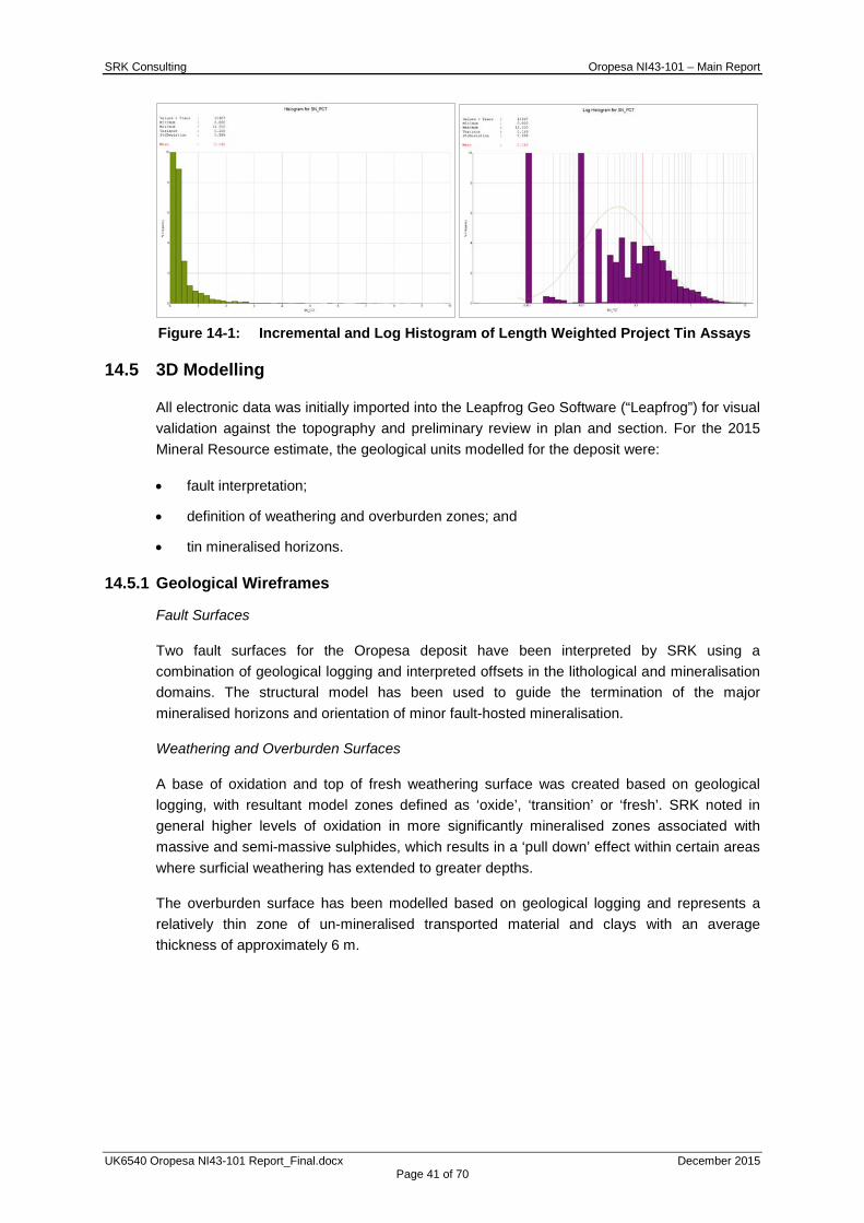
SRK Consulting Oropesa NI43-101 – Main Report
UK6540 Oropesa NI43-101 Report_Final.docx December 2015 Page 41 of 70
Figure 14-1: Incremental and Log Histogram of Length Weighted Project Tin Assays
14.5 3D Modelling
All electronic data was initially imported into the Leapfrog Geo Software (“Leapfrog”) for visual validation against the topography and preliminary review in plan and section. For the 2015 Mineral Resource estimate, the geological units modelled for the deposit were:
• fault interpretation;
• definition of weathering and overburden zones; and
• tin mineralised horizons.
14.5.1 Geological Wireframes
Fault Surfaces
Two fault surfaces for the Oropesa deposit have been interpreted by SRK using a combination of geological logging and interpreted offsets in the lithological and mineralisation domains. The structural model has been used to guide the termination of the major mineralised horizons and orientation of minor fault-hosted mineralisation.
Weathering and Overburden Surfaces
A base of oxidation and top of fresh weathering surface was created based on geological logging, with resultant model zones defined as ‘oxide’, ‘transition’ or ‘fresh’. SRK noted in general higher levels of oxidation in more significantly mineralised zones associated with massive and semi-massive sulphides, which results in a ‘pull down’ effect within certain areas where surficial weathering has extended to greater depths.
The overburden surface has been modelled based on geological logging and represents a relatively thin zone of un-mineralised transported material and clays with an average thickness of approximately 6 m.

SRK Consulting Oropesa NI43-101 – Main Report
UK6540 Oropesa NI43-101 Report_Final.docx December 2015 Page 42 of 70
14.5.2 Mineralisation Wireframes
Tin Mineralised Horizons
For the October 2015 Mineral Resource update, based on additional exploration work, SRK has updated the geological interpretation for the Oropesa Project to reflect a more stratabound and folded mineralisation model. Mineralised horizons have been defined based on a combination of lithological logging and tin grade whilst honouring the structural controls and ensuring geological and grade continuity. Top and bottom contacts reflect a cut-off of 0.25% tin (Sn) to differentiate mineralised layers from lower grade host rock and internal partings.
SRK created 3D solid wireframes from selected sample intervals using the vein tool in the Leapfrog Geo Software (“Leapfrog”).
An example 3D image showing the tin mineralised horizons in context of the modelled fault surfaces is provided in Figure 14-2.
Figure 14-2: 3D view (looking NE) illustrating the position and orientation of the
mineralised horizons and faulting at Oropesa
14.5.3 Mineralisation Model Coding
A summary of the mineralisation horizons versus statistical and estimation zone code and modelled wireframe name for Oropesa is provided in Table 14-1. The GROUP code relates to the mineralisation domain globally, whereas the KZONE code relates to individual mineralised horizons.
Fault surface (grey)
Tin mineralised horizons (green)
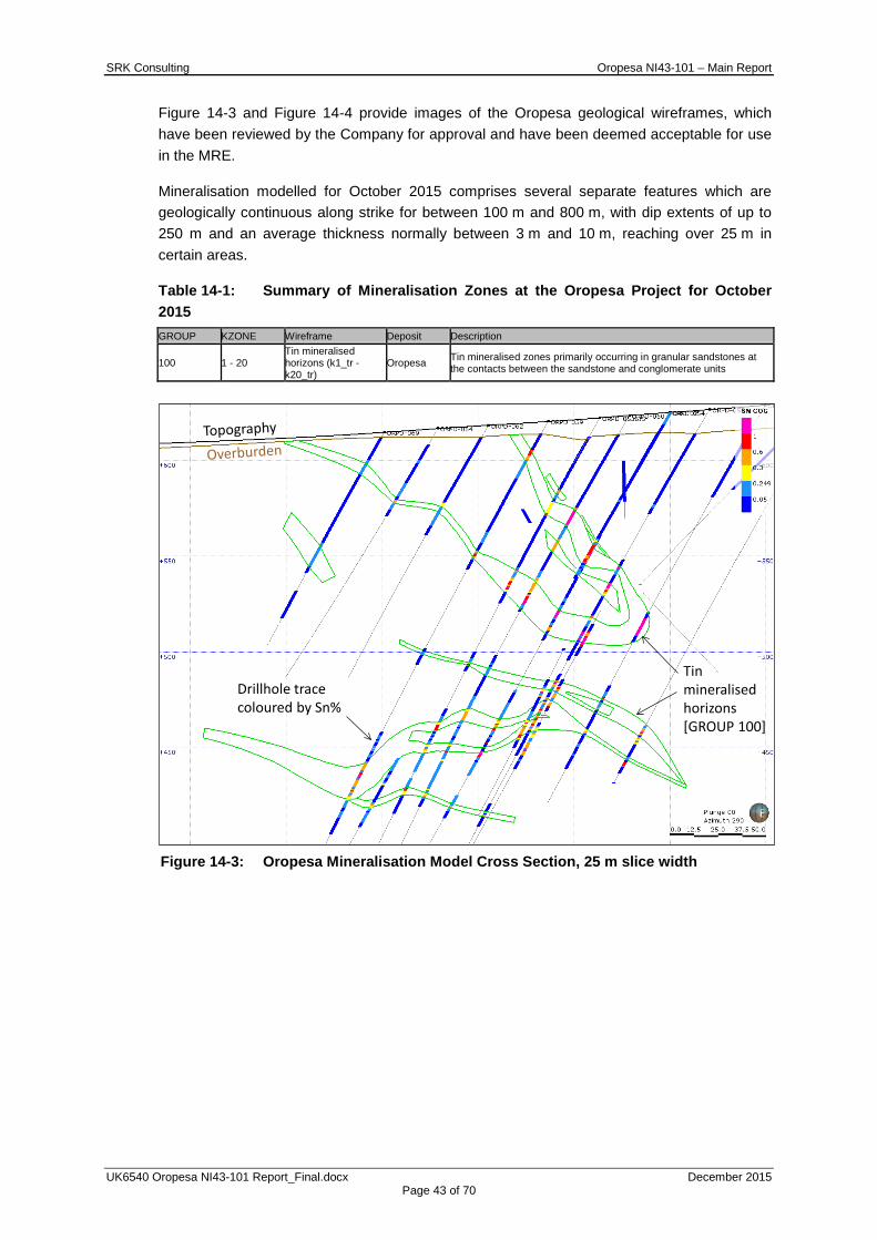
SRK Consulting Oropesa NI43-101 – Main Report
UK6540 Oropesa NI43-101 Report_Final.docx December 2015 Page 43 of 70
Figure 14-3 and Figure 14-4 provide images of the Oropesa geological wireframes, which have been reviewed by the Company for approval and have been deemed acceptable for use in the MRE.
Mineralisation modelled for October 2015 comprises several separate features which are geologically continuous along strike for between 100 m and 800 m, with dip extents of up to 250 m and an average thickness normally between 3 m and 10 m, reaching over 25 m in certain areas.
Table 14-1: Summary of Mineralisation Zones at the Oropesa Project for October 2015 GROUP KZONE Wireframe Deposit Description
100 1 - 20 Tin mineralised horizons (k1_tr - k20_tr)
Oropesa Tin mineralised zones primarily occurring in granular sandstones at the contacts between the sandstone and conglomerate units
Figure 14-3: Oropesa Mineralisation Model Cross Section, 25 m slice width
Drillhole trace coloured by Sn%
Tin mineralised horizons [GROUP 100]

SRK Consulting Oropesa NI43-101 – Main Report
UK6540 Oropesa NI43-101 Report_Final.docx December 2015 Page 44 of 70
Figure 14-4: Oropesa Mineralisation Model Plan View
14.6 Compositing
Prior to the undertaking of a statistical analysis, the samples are typically composited into equal lengths to provide a constant sample volume, honouring sample support theories.
The tin grade data at Oropesa shows that there are higher and lower grade patches areas within the deposit, however there are no clearly predictable grade trends from top to bottom contact in the mineralised horizons. Therefore, whilst the mean sample length is 1.6 m, SRK elected to create a single composite for each of the drillholes per intersected horizon (‘zone-composites’) to ensure variography and block grade estimation focused on variability along strike and along dip. Where drillholes intersect the horizon at a very shallow angle, the data have been used, but in this case, often several composites were made with a maximum length of 40 m.
14.7 Evaluation of Outliers
High grade capping is undertaken where data is no longer considered to be part of the main population. SRK has completed the analysis based on log probability plots, raw and log histograms which can be used to distinguish the grades at which samples have significant impacts on the local estimation and whose affect is considered extreme. Based on a review of raw and log histogram plots for the mineralisation domain (in context of a visual assessment for sample support), no high-grade capping was applied.
Log histograms and log-probability plots (as illustrated for tin zone-composites in Figure 14-5) are shown for the mineralisation domain in Appendix B, which also presents capping analysis based on 2 m composites to illustrate in general the limited sensitivity on the outlier assessment to composite length. Table 14-2 and Table 14-3 provide a summary of the zone-composite sample statistics within the mineralisation domain and individual mineralised horizons, respectively.
Tin mineralised horizons [GROUP 100]
Fault surfaces
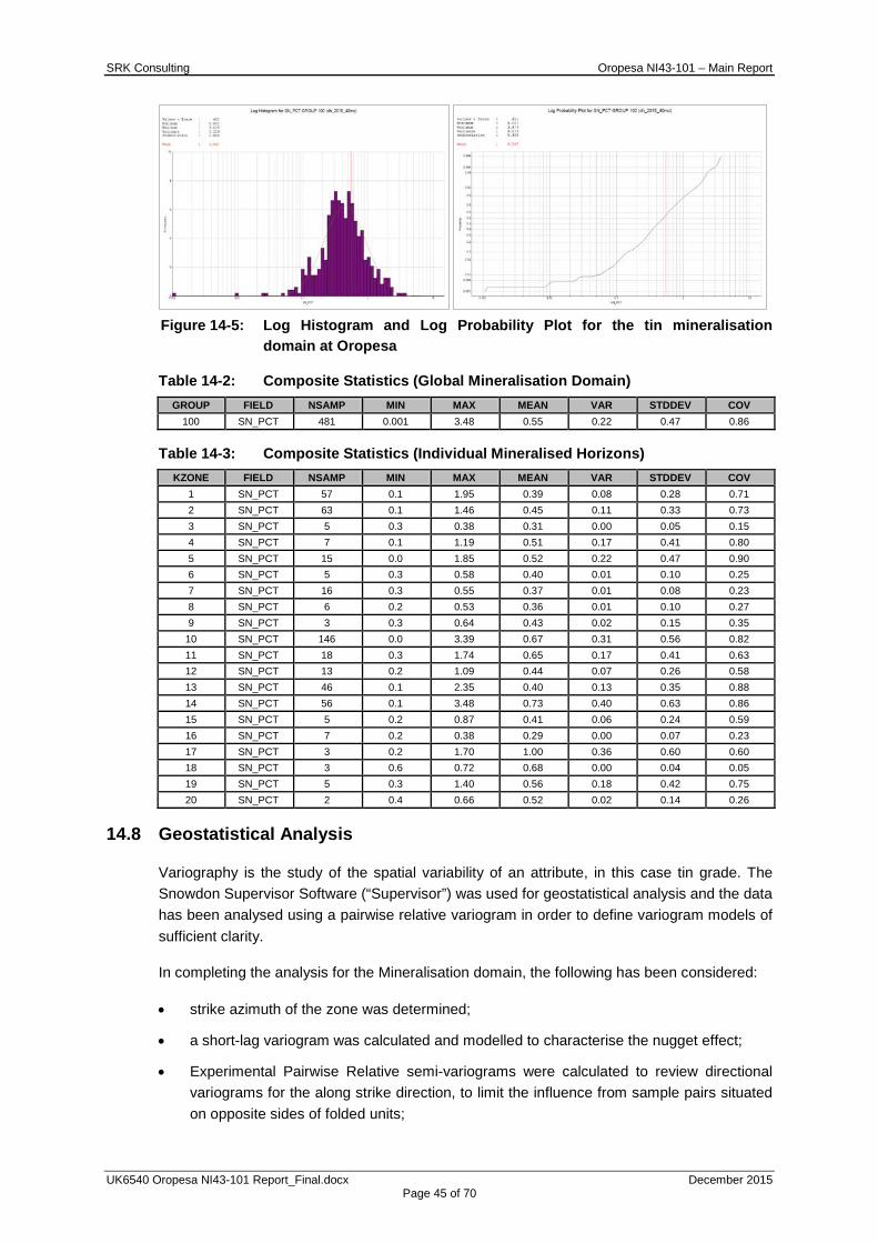
SRK Consulting Oropesa NI43-101 – Main Report
UK6540 Oropesa NI43-101 Report_Final.docx December 2015 Page 45 of 70
Figure 14-5: Log Histogram and Log Probability Plot for the tin mineralisation
domain at Oropesa
Table 14-2: Composite Statistics (Global Mineralisation Domain) GROUP FIELD NSAMP MIN MAX MEAN VAR STDDEV COV
100 SN_PCT 481 0.001 3.48 0.55 0.22 0.47 0.86
Table 14-3: Composite Statistics (Individual Mineralised Horizons) KZONE FIELD NSAMP MIN MAX MEAN VAR STDDEV COV
1 SN_PCT 57 0.1 1.95 0.39 0.08 0.28 0.71 2 SN_PCT 63 0.1 1.46 0.45 0.11 0.33 0.73 3 SN_PCT 5 0.3 0.38 0.31 0.00 0.05 0.15 4 SN_PCT 7 0.1 1.19 0.51 0.17 0.41 0.80 5 SN_PCT 15 0.0 1.85 0.52 0.22 0.47 0.90 6 SN_PCT 5 0.3 0.58 0.40 0.01 0.10 0.25 7 SN_PCT 16 0.3 0.55 0.37 0.01 0.08 0.23 8 SN_PCT 6 0.2 0.53 0.36 0.01 0.10 0.27 9 SN_PCT 3 0.3 0.64 0.43 0.02 0.15 0.35
10 SN_PCT 146 0.0 3.39 0.67 0.31 0.56 0.82 11 SN_PCT 18 0.3 1.74 0.65 0.17 0.41 0.63 12 SN_PCT 13 0.2 1.09 0.44 0.07 0.26 0.58 13 SN_PCT 46 0.1 2.35 0.40 0.13 0.35 0.88 14 SN_PCT 56 0.1 3.48 0.73 0.40 0.63 0.86 15 SN_PCT 5 0.2 0.87 0.41 0.06 0.24 0.59 16 SN_PCT 7 0.2 0.38 0.29 0.00 0.07 0.23 17 SN_PCT 3 0.2 1.70 1.00 0.36 0.60 0.60 18 SN_PCT 3 0.6 0.72 0.68 0.00 0.04 0.05 19 SN_PCT 5 0.3 1.40 0.56 0.18 0.42 0.75 20 SN_PCT 2 0.4 0.66 0.52 0.02 0.14 0.26
14.8 Geostatistical Analysis
Variography is the study of the spatial variability of an attribute, in this case tin grade. The Snowdon Supervisor Software (“Supervisor”) was used for geostatistical analysis and the data has been analysed using a pairwise relative variogram in order to define variogram models of sufficient clarity.
In completing the analysis for the Mineralisation domain, the following has been considered:
• strike azimuth of the zone was determined;
• a short-lag variogram was calculated and modelled to characterise the nugget effect;
• Experimental Pairwise Relative semi-variograms were calculated to review directional variograms for the along strike direction, to limit the influence from sample pairs situated on opposite sides of folded units;
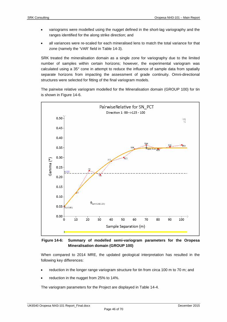
SRK Consulting Oropesa NI43-101 – Main Report
UK6540 Oropesa NI43-101 Report_Final.docx December 2015 Page 46 of 70
• variograms were modelled using the nugget defined in the short-lag variography and the ranges identified for the along strike direction; and
• all variances were re-scaled for each mineralised lens to match the total variance for that zone (namely the ‘VAR’ field in Table 14-3).
SRK treated the mineralisation domain as a single zone for variography due to the limited number of samples within certain horizons; however, the experimental variogram was calculated using a 35° cone in attempt to reduce the influence of sample data from spatially separate horizons from impacting the assessment of grade continuity. Omni-directional structures were selected for fitting of the final variogram models.
The pairwise relative variogram modelled for the Mineralisation domain (GROUP 100) for tin is shown in Figure 14-6.
Figure 14-6: Summary of modelled semi-variogram parameters for the Oropesa
Mineralisation domain (GROUP 100)
When compared to 2014 MRE, the updated geological interpretation has resulted in the following key differences:
• reduction in the longer range variogram structure for tin from circa 100 m to 70 m; and
• reduction in the nugget from 25% to 14%.
The variogram parameters for the Project are displayed in Table 14-4.

SRK Consulting Oropesa NI43-101 – Main Report
UK6540 Oropesa NI43-101 Report_Final.docx December 2015 Page 47 of 70
Table 14-4: Summary of semi-variogram parameters* Variogram Parameter SN_PCT-GROUP100
Co 0.05 C1 0.02
A1 – Along Strike (m) 23 A1 – Down Dip (m) 23
A1 – Across Strike (m) 23 C2 0.28
A2 – Along Strike (m) 70 A2 – Down Dip (m) 70
A2 – Across Strike (m) 70 C3 0.00
A3 – Along Strike (m) 0 A3 – Down Dip (m) 0
A3 – Across Strike (m) 0 Nugget Effect (%) 14%
*Semi-variogram structures are subsequently re-scaled to the total sample variance per estimation zone
14.9 Block Model and Grade Estimation
A block model prototype was created for Oropesa based on UTM coordinate grid. Block model parameters were chosen to reflect the average drillhole spacing (along strike and on section) and to appropriately reflect the grade variability along strike and along dip.
To improve the geometric representation of the geological model, sub-blocking was allowed along the boundaries to a minimum of 2x2x1 m (x, y, and z). A summary of the block model parameters is given in Table 14-5. Using the wireframes created and described in Section 14.5, several codes have been written in the block model to describe each of the major geological properties of the rock types. Table 14-6 summarises geological fields created within the block model and the codes used.
Table 14-5: Details of Block Model Dimensions for the Project Geological Model Model Dimension Origin (UTM) Block Size Number of Blocks Min Sub-blocking (m)
Oropesa X 282680 20 81 2 Y 4242800 20 65 2 Z 250 10 45 1
Table 14-6: Summary of block model fields used for flagging different geological properties
Field Name Description SVOL Search Volume reference (range from 1 - 3) KV Kriging Variance NSUM Number of samples used to estimate the block SN Interpolated tin value CLASS Classification KZONE Zone for estimation GROUP Zone for statistical analysis CLASS Classification DENSITY Density of the rock OXZONE Zone for density estimation OX Weathering zone (1=oxide; 2=transition; 3=fresh) OVB Overburden zone code (1=overburden)
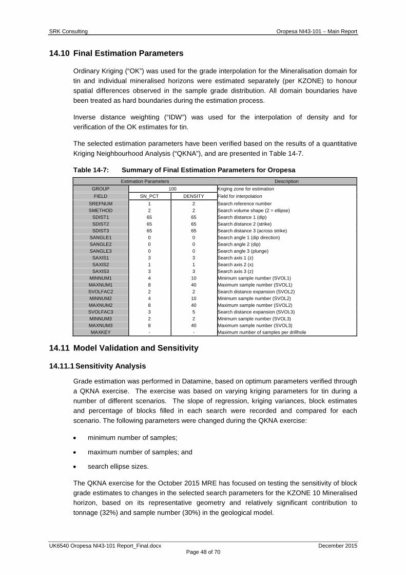
SRK Consulting Oropesa NI43-101 – Main Report
UK6540 Oropesa NI43-101 Report_Final.docx December 2015 Page 48 of 70
14.10 Final Estimation Parameters
Ordinary Kriging (“OK”) was used for the grade interpolation for the Mineralisation domain for tin and individual mineralised horizons were estimated separately (per KZONE) to honour spatial differences observed in the sample grade distribution. All domain boundaries have been treated as hard boundaries during the estimation process.
Inverse distance weighting (“IDW”) was used for the interpolation of density and for verification of the OK estimates for tin.
The selected estimation parameters have been verified based on the results of a quantitative Kriging Neighbourhood Analysis (“QKNA”), and are presented in Table 14-7.
Table 14-7: Summary of Final Estimation Parameters for Oropesa Estimation Parameters Description
GROUP 100 Kriging zone for estimation FIELD SN_PCT DENSITY Field for interpolation
SREFNUM 1 2 Search reference number SMETHOD 2 2 Search volume shape (2 = ellipse)
SDIST1 65 65 Search distance 1 (dip) SDIST2 65 65 Search distance 2 (strike) SDIST3 65 65 Search distance 3 (across strike)
SANGLE1 0 0 Search angle 1 (dip direction) SANGLE2 0 0 Search angle 2 (dip) SANGLE3 0 0 Search angle 3 (plunge) SAXIS1 3 3 Search axis 1 (z) SAXIS2 1 1 Search axis 2 (x) SAXIS3 3 3 Search axis 3 (z)
MINNUM1 4 10 Minimum sample number (SVOL1) MAXNUM1 8 40 Maximum sample number (SVOL1) SVOLFAC2 2 2 Search distance expansion (SVOL2) MINNUM2 4 10 Minimum sample number (SVOL2) MAXNUM2 8 40 Maximum sample number (SVOL2) SVOLFAC3 3 5 Search distance expansion (SVOL3) MINNUM3 2 2 Minimum sample number (SVOL3) MAXNUM3 8 40 Maximum sample number (SVOL3) MAXKEY - - Maximum number of samples per drillhole
14.11 Model Validation and Sensitivity
14.11.1 Sensitivity Analysis
Grade estimation was performed in Datamine, based on optimum parameters verified through a QKNA exercise. The exercise was based on varying kriging parameters for tin during a number of different scenarios. The slope of regression, kriging variances, block estimates and percentage of blocks filled in each search were recorded and compared for each scenario. The following parameters were changed during the QKNA exercise:
• minimum number of samples;
• maximum number of samples; and
• search ellipse sizes.
The QKNA exercise for the October 2015 MRE has focused on testing the sensitivity of block grade estimates to changes in the selected search parameters for the KZONE 10 Mineralised horizon, based on its representative geometry and relatively significant contribution to tonnage (32%) and sample number (30%) in the geological model.
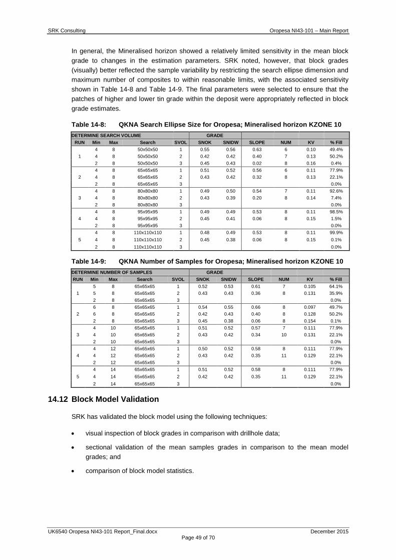
SRK Consulting Oropesa NI43-101 – Main Report
UK6540 Oropesa NI43-101 Report_Final.docx December 2015 Page 49 of 70
In general, the Mineralised horizon showed a relatively limited sensitivity in the mean block grade to changes in the estimation parameters. SRK noted, however, that block grades (visually) better reflected the sample variability by restricting the search ellipse dimension and maximum number of composites to within reasonable limits, with the associated sensitivity shown in Table 14-8 and Table 14-9. The final parameters were selected to ensure that the patches of higher and lower tin grade within the deposit were appropriately reflected in block grade estimates.
Table 14-8: QKNA Search Ellipse Size for Oropesa; Mineralised horizon KZONE 10 DETERMINE SEARCH VOLUME GRADE
RUN Min Max Search SVOL SNOK SNIDW SLOPE NUM KV % Fill
1 4 8 50x50x50 1 0.55 0.56 0.63 6 0.10 49.4% 4 8 50x50x50 2 0.42 0.42 0.40 7 0.13 50.2% 2 8 50x50x50 3 0.45 0.43 0.02 8 0.16 0.4%
2 4 8 65x65x65 1 0.51 0.52 0.56 6 0.11 77.9% 4 8 65x65x65 2 0.43 0.42 0.32 8 0.13 22.1% 2 8 65x65x65 3 0.0%
3 4 8 80x80x80 1 0.49 0.50 0.54 7 0.11 92.6% 4 8 80x80x80 2 0.43 0.39 0.20 8 0.14 7.4% 2 8 80x80x80 3 0.0%
4 4 8 95x95x95 1 0.49 0.49 0.53 8 0.11 98.5% 4 8 95x95x95 2 0.45 0.41 0.06 8 0.15 1.5% 2 8 95x95x95 3 0.0%
5 4 8 110x110x110 1 0.48 0.49 0.53 8 0.11 99.9% 4 8 110x110x110 2 0.45 0.38 0.06 8 0.15 0.1% 2 8 110x110x110 3 0.0%
Table 14-9: QKNA Number of Samples for Oropesa; Mineralised horizon KZONE 10 DETERMINE NUMBER OF SAMPLES GRADE RUN Min Max Search SVOL SNOK SNIDW SLOPE NUM KV % Fill
1 5 8 65x65x65 1 0.52 0.53 0.61 7 0.105 64.1% 5 8 65x65x65 2 0.43 0.43 0.36 8 0.131 35.9% 2 8 65x65x65 3 0.0%
2 6 8 65x65x65 1 0.54 0.55 0.66 8 0.097 49.7% 6 8 65x65x65 2 0.42 0.43 0.40 8 0.128 50.2% 2 8 65x65x65 3 0.45 0.38 0.06 8 0.154 0.1%
3 4 10 65x65x65 1 0.51 0.52 0.57 7 0.111 77.9% 4 10 65x65x65 2 0.43 0.42 0.34 10 0.131 22.1% 2 10 65x65x65 3 0.0%
4 4 12 65x65x65 1 0.50 0.52 0.58 8 0.111 77.9% 4 12 65x65x65 2 0.43 0.42 0.35 11 0.129 22.1% 2 12 65x65x65 3 0.0%
5 4 14 65x65x65 1 0.51 0.52 0.58 8 0.111 77.9% 4 14 65x65x65 2 0.42 0.42 0.35 11 0.129 22.1% 2 14 65x65x65 3 0.0%
14.12 Block Model Validation
SRK has validated the block model using the following techniques:
• visual inspection of block grades in comparison with drillhole data;
• sectional validation of the mean samples grades in comparison to the mean model grades; and
• comparison of block model statistics.

SRK Consulting Oropesa NI43-101 – Main Report
UK6540 Oropesa NI43-101 Report_Final.docx December 2015 Page 50 of 70
Visual Validation
Visual validation provides a comparison of the interpolated block model on a local scale. A thorough visual inspection has been undertaken in section and 3D, comparing the sample grades with the block grades, which demonstrates in general good comparison between local block estimates and nearby samples, without excessive smoothing in the block model. Figure 14-7 shows an example of the visual validation checks and highlights the overall block grades corresponding with composite sample grades. Further visual validation images are shown in Appendix C.
Figure 14-7: Oropesa Block Model 3D view showing visual validation of modelled
borehole intercepts to grade estimates
Sectional Validation
As part of the validation process, the input composite samples are compared to the block model grades within a series of coordinates (based on the principle directions). The results of which are then displayed on charts to check for visual discrepancies between grades. Figure 14-8 shows the results for the tin grades for the Mineralised horizon KZONE 10 based on section lines cut along x-coordinates.
The resultant plots show a reasonable correlation between the block model grades and the composite grades, with the block model showing a typically smoothed profile of the composite grades as expected. SRK notes that in less densely sampled areas, minor grade discrepancies do exist on a local scale. Overall, however, SRK is confident that the interpolated grades reflect the available input sample data and the estimate shows no sign of material bias.
Validation plots for selected Mineralised horizons are shown in Appendix D.
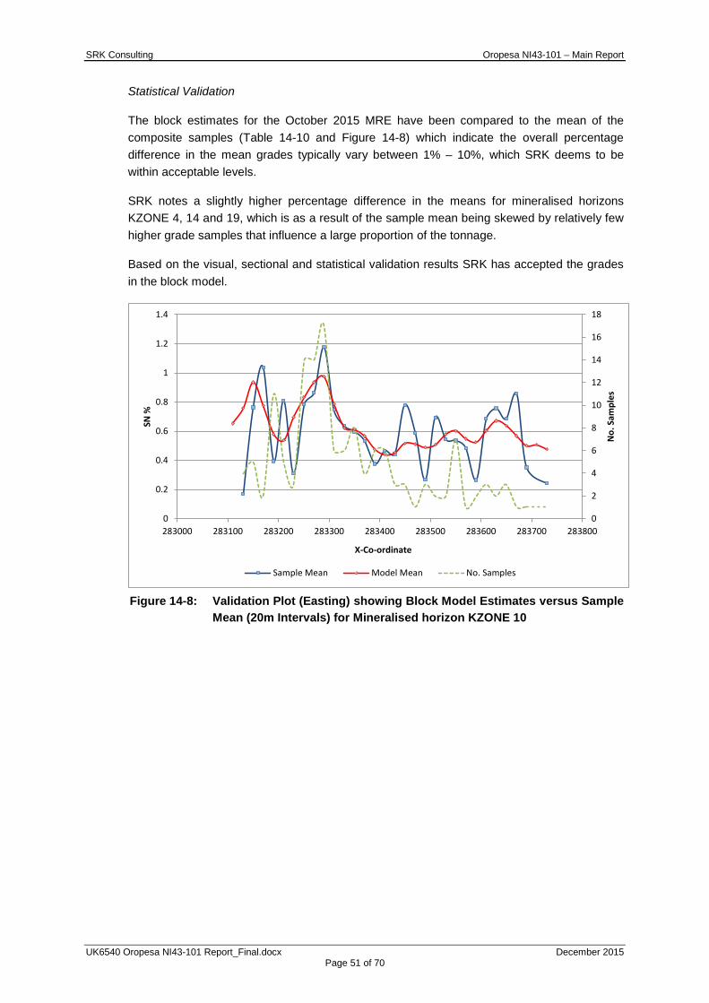
SRK Consulting Oropesa NI43-101 – Main Report
UK6540 Oropesa NI43-101 Report_Final.docx December 2015 Page 51 of 70
Statistical Validation
The block estimates for the October 2015 MRE have been compared to the mean of the composite samples (Table 14-10 and Figure 14-8) which indicate the overall percentage difference in the mean grades typically vary between 1% – 10%, which SRK deems to be within acceptable levels.
SRK notes a slightly higher percentage difference in the means for mineralised horizons KZONE 4, 14 and 19, which is as a result of the sample mean being skewed by relatively few higher grade samples that influence a large proportion of the tonnage.
Based on the visual, sectional and statistical validation results SRK has accepted the grades in the block model.
Figure 14-8: Validation Plot (Easting) showing Block Model Estimates versus Sample
Mean (20m Intervals) for Mineralised horizon KZONE 10
0
2
4
6
8
10
12
14
16
18
0
0.2
0.4
0.6
0.8
1
1.2
1.4
283000 283100 283200 283300 283400 283500 283600 283700 283800
No.
Sam
ples
SN %
X-Co-ordinate
Sample Mean Model Mean No. Samples
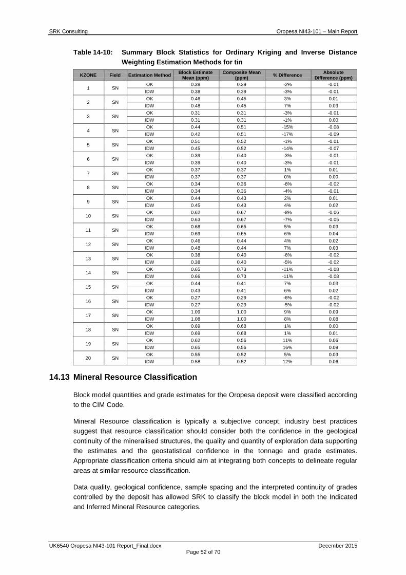
SRK Consulting Oropesa NI43-101 – Main Report
UK6540 Oropesa NI43-101 Report_Final.docx December 2015 Page 52 of 70
Table 14-10: Summary Block Statistics for Ordinary Kriging and Inverse Distance Weighting Estimation Methods for tin
KZONE Field Estimation Method Block Estimate Mean (ppm)
Composite Mean (ppm) % Difference Absolute
Difference (ppm)
1 SN OK 0.38 0.39 -2% -0.01 IDW 0.38 0.39 -3% -0.01
2 SN OK 0.46 0.45 3% 0.01 IDW 0.48 0.45 7% 0.03
3 SN OK 0.31 0.31 -3% -0.01 IDW 0.31 0.31 -1% 0.00
4 SN OK 0.44 0.51 -15% -0.08 IDW 0.42 0.51 -17% -0.09
5 SN OK 0.51 0.52 -1% -0.01 IDW 0.45 0.52 -14% -0.07
6 SN OK 0.39 0.40 -3% -0.01 IDW 0.39 0.40 -3% -0.01
7 SN OK 0.37 0.37 1% 0.01 IDW 0.37 0.37 0% 0.00
8 SN OK 0.34 0.36 -6% -0.02 IDW 0.34 0.36 -4% -0.01
9 SN OK 0.44 0.43 2% 0.01 IDW 0.45 0.43 4% 0.02
10 SN OK 0.62 0.67 -8% -0.06 IDW 0.63 0.67 -7% -0.05
11 SN OK 0.68 0.65 5% 0.03 IDW 0.69 0.65 6% 0.04
12 SN OK 0.46 0.44 4% 0.02 IDW 0.48 0.44 7% 0.03
13 SN OK 0.38 0.40 -6% -0.02 IDW 0.38 0.40 -5% -0.02
14 SN OK 0.65 0.73 -11% -0.08 IDW 0.66 0.73 -11% -0.08
15 SN OK 0.44 0.41 7% 0.03 IDW 0.43 0.41 6% 0.02
16 SN OK 0.27 0.29 -6% -0.02 IDW 0.27 0.29 -5% -0.02
17 SN OK 1.09 1.00 9% 0.09 IDW 1.08 1.00 8% 0.08
18 SN OK 0.69 0.68 1% 0.00 IDW 0.69 0.68 1% 0.01
19 SN OK 0.62 0.56 11% 0.06 IDW 0.65 0.56 16% 0.09
20 SN OK 0.55 0.52 5% 0.03 IDW 0.58 0.52 12% 0.06
14.13 Mineral Resource Classification
Block model quantities and grade estimates for the Oropesa deposit were classified according to the CIM Code.
Mineral Resource classification is typically a subjective concept, industry best practices suggest that resource classification should consider both the confidence in the geological continuity of the mineralised structures, the quality and quantity of exploration data supporting the estimates and the geostatistical confidence in the tonnage and grade estimates. Appropriate classification criteria should aim at integrating both concepts to delineate regular areas at similar resource classification.
Data quality, geological confidence, sample spacing and the interpreted continuity of grades controlled by the deposit has allowed SRK to classify the block model in both the Indicated and Inferred Mineral Resource categories.
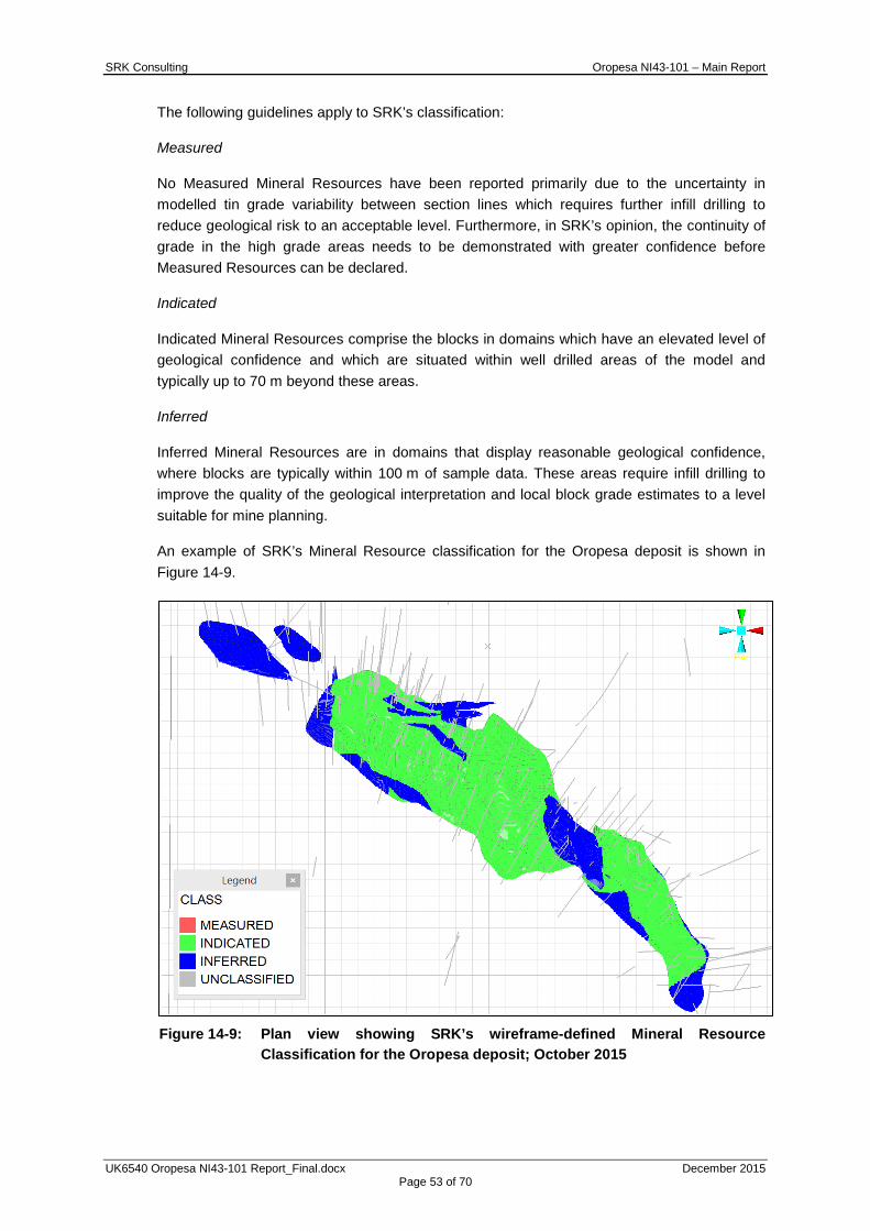
SRK Consulting Oropesa NI43-101 – Main Report
UK6540 Oropesa NI43-101 Report_Final.docx December 2015 Page 53 of 70
The following guidelines apply to SRK’s classification:
Measured
No Measured Mineral Resources have been reported primarily due to the uncertainty in modelled tin grade variability between section lines which requires further infill drilling to reduce geological risk to an acceptable level. Furthermore, in SRK’s opinion, the continuity of grade in the high grade areas needs to be demonstrated with greater confidence before Measured Resources can be declared.
Indicated
Indicated Mineral Resources comprise the blocks in domains which have an elevated level of geological confidence and which are situated within well drilled areas of the model and typically up to 70 m beyond these areas.
Inferred
Inferred Mineral Resources are in domains that display reasonable geological confidence, where blocks are typically within 100 m of sample data. These areas require infill drilling to improve the quality of the geological interpretation and local block grade estimates to a level suitable for mine planning.
An example of SRK’s Mineral Resource classification for the Oropesa deposit is shown in Figure 14-9.
Figure 14-9: Plan view showing SRK’s wireframe-defined Mineral Resource
Classification for the Oropesa deposit; October 2015

SRK Consulting Oropesa NI43-101 – Main Report
UK6540 Oropesa NI43-101 Report_Final.docx December 2015 Page 54 of 70
14.14 Mineral Resource Statement
The CIM Code defines a Mineral Resource as:
A “concentration or occurrence of diamonds, natural solid inorganic material, or natural solid fossilized organic material including base and precious metals, coal, and industrial minerals in or on the Earth’s crust in such form and quantity and of such a grade or quality that it has reasonable prospects for economic extraction. The location, quantity, grade, geological characteristics and continuity of a Mineral Resource are known, estimated or interpreted from specific geological evidence and knowledge”.
The “reasonable prospects for eventual economic extraction” requirement generally implies that the quantity and grade estimates meet certain economic thresholds and that the mineral resources are reported at an appropriate cut-off grade taking into account extraction scenarios and processing recoveries.
Reporting and Cut-off Derivation
SRK has applied basic economic considerations to determine which portion of the block model has reasonable prospects for economic extraction by open-pit mining methods. To achieve this, the Mineral Resource has been subject to a high-level pit optimisation study to assist with determining the potential depth to which an open pit operation could be considered viable and reported above a suitable cut-off grade for resource reporting.
The results of the optimisation study for 2015 showed that an open pit operation could potentially be supported to a depth of 235 m (close to the bottom of the model) and that a lower cut-off grade of 0.1% Sn is appropriate. SRK has elected to consider the full extents of the geological model for resource reporting.
The 2015 Mineral Resource Statement for the Oropesa deposit is shown per weathering zone and grade category in Table 14-11. The Company has satisfied all conditions to receive a 100% interest in the Oropesa property and anticipates that registered title to the property will be transferred to the Company within several months of filing the transfer documents with the Andalucia mining authorities under the Spanish Mining Act.
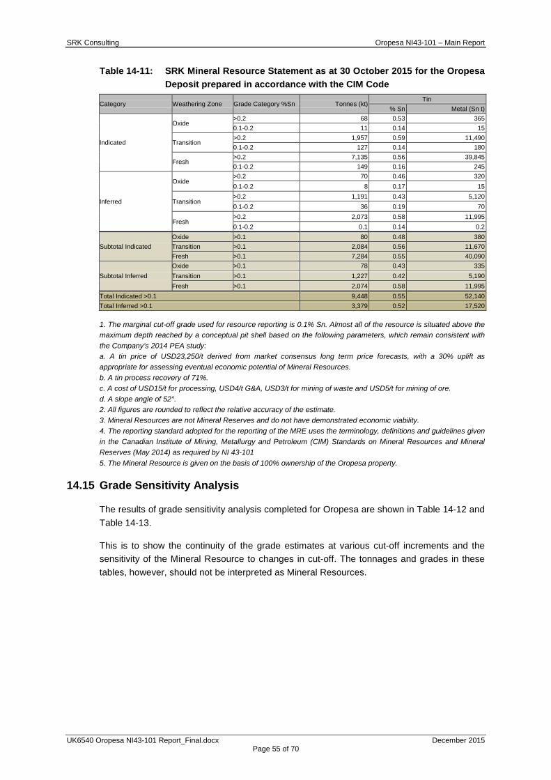
SRK Consulting Oropesa NI43-101 – Main Report
UK6540 Oropesa NI43-101 Report_Final.docx December 2015 Page 55 of 70
Table 14-11: SRK Mineral Resource Statement as at 30 October 2015 for the Oropesa Deposit prepared in accordance with the CIM Code
Category Weathering Zone Grade Category %Sn Tonnes (kt) Tin
% Sn Metal (Sn t)
Indicated
Oxide >0.2 68 0.53 365 0.1-0.2 11 0.14 15
Transition >0.2 1,957 0.59 11,490 0.1-0.2 127 0.14 180
Fresh >0.2 7,135 0.56 39,845 0.1-0.2 149 0.16 245
Inferred
Oxide >0.2 70 0.46 320 0.1-0.2 8 0.17 15
Transition >0.2 1,191 0.43 5,120 0.1-0.2 36 0.19 70
Fresh >0.2 2,073 0.58 11,995 0.1-0.2 0.1 0.14 0.2
Subtotal Indicated Oxide >0.1 80 0.48 380 Transition >0.1 2,084 0.56 11,670 Fresh >0.1 7,284 0.55 40,090
Subtotal Inferred Oxide >0.1 78 0.43 335 Transition >0.1 1,227 0.42 5,190 Fresh >0.1 2,074 0.58 11,995
Total Indicated >0.1 9,448 0.55 52,140 Total Inferred >0.1 3,379 0.52 17,520
1. The marginal cut-off grade used for resource reporting is 0.1% Sn. Almost all of the resource is situated above the maximum depth reached by a conceptual pit shell based on the following parameters, which remain consistent with the Company’s 2014 PEA study: a. A tin price of USD23,250/t derived from market consensus long term price forecasts, with a 30% uplift as appropriate for assessing eventual economic potential of Mineral Resources. b. A tin process recovery of 71%. c. A cost of USD15/t for processing, USD4/t G&A, USD3/t for mining of waste and USD5/t for mining of ore. d. A slope angle of 52°. 2. All figures are rounded to reflect the relative accuracy of the estimate. 3. Mineral Resources are not Mineral Reserves and do not have demonstrated economic viability. 4. The reporting standard adopted for the reporting of the MRE uses the terminology, definitions and guidelines given in the Canadian Institute of Mining, Metallurgy and Petroleum (CIM) Standards on Mineral Resources and Mineral Reserves (May 2014) as required by NI 43-101 5. The Mineral Resource is given on the basis of 100% ownership of the Oropesa property.
14.15 Grade Sensitivity Analysis
The results of grade sensitivity analysis completed for Oropesa are shown in Table 14-12 and Table 14-13.
This is to show the continuity of the grade estimates at various cut‐off increments and the sensitivity of the Mineral Resource to changes in cut-off. The tonnages and grades in these tables, however, should not be interpreted as Mineral Resources.

SRK Consulting Oropesa NI43-101 – Main Report
UK6540 Oropesa NI43-101 Report_Final.docx December 2015 Page 56 of 70
Table 14-12: Gradations for Indicated Material at Oropesa at various %Sn Cut-off Grades
Grade - Tonnage Table, Oropesa, October 2015*
Cut-off Grade Indicated
Quantity Tin Sn (%) (Mt) % Sn Metal (Sn kt)
0.10 9.4 0.55 52.1 0.20 9.2 0.56 51.7 0.30 8.1 0.60 49.0 0.40 6.7 0.66 43.9 0.50 4.9 0.73 35.9 0.60 3.4 0.81 27.5
Table 14-13: Gradations for Inferred Material at Oropesa at various %Sn Cut-off Grades
Grade - Tonnage Table, Oropesa, October 2015*
Cut-off Grade Inferred
Quantity Tin Sn (%) (Mt) % Sn Metal (Sn kt)
0.10 3.4 0.52 17.5 0.20 3.3 0.52 17.4 0.30 3.0 0.55 16.5 0.40 2.0 0.65 13.0 0.50 1.2 0.79 9.6 0.60 0.9 0.86 8.1
14.16 Vertical Profile Analysis
SRK has completed a vertical profile analysis of the classified Mineral Resource grouped over 10m increments to illustrate the nature of the grade and tonnages of the mineralisation with depth. To illustrate the sensitivity of the vertical profiles to cut-off gradations, separate tabulations are provided above cut-off grades of 0.1%, 0.2% and 0.25% Sn and are presented in Appendix E. The reader is cautioned that the tables presented should not be misconstrued with a Mineral Resource Statement.
The vertical profile plot at a 0.1% Sn cut-off shows that the material classified as Indicated has an overall higher grade in the top half of the model (above 480m RL i.e. to depth of 140 m). The grade in the top half is 0.58% Sn, whereas the lower half of the model has a slightly lower grade at 0.52% Sn.
14.17 Comparison to Previous Mineral Resource Estimates
In comparison to the 2014 MRE for the Oropesa Project, which was also reported at a cut-off grade of 0.1% Sn, the new estimate has a marginal reduction in metal content decreasing from 70.8 kt to 69.7 kt of contained tin. The change in contained metal is the result of 33% reduction in tonnage, with an overall 47% increase in the tin grade at the 0.1% Sn cut-off.
SRK considers that the key changes in the Mineral Resource at the Oropesa Project result from a combination of the following factors:
• updated geological interpretation for the Oropesa Project to reflect a more strongly lithologically controlled mineralisation model;
• increase in the wireframe modelling cut-off from 0.1% Sn to 0.25% Sn;
• reporting of additional block model material at depth, supported by the updated pit optimisation exercise for October 2015, which has driven the conceptual pit deeper when compared to the 2014 MRE;
SRK Consulting Oropesa NI43-101 – Main Report
UK6540 Oropesa NI43-101 Report_Final.docx December 2015 Page 57 of 70
• less mixing of low grades and high grades based on the revised geological interpretation; and
• minor exploration drilling and the addition of assays from a limited number of previously non-sampled intercepts and sample results which were not available during the 2014 MRE.
14.18 Exploration Potential
SRK notes that the mineralisation remains open along strike and around the margins of the deposit where there is potential for additional replacement-style and/or fault-controlled mineralisation.
Furthermore, the updated geological model used to guide the development of the mineralisation wireframes has significant implications for exploration in the surrounding area. The geological model should be further tested and refined in conjunction with a reassessment of the licence scale exploration potential.
In addition, SRK considers that within certain areas lower grade material of between 0.1-0.25% Sn exists adjacent to the current Resource model, with the potential to host between 1.5-3.0 Mt of low grade mineralisation.
15 MINERAL RESERVE ESTIMATES SRK has not produced a Mineral Reserve Estimate for the Oropesa Project. Mineral Reserves cannot be reported until a Preliminary Feasibility Study is completed.
16 MINING METHODS SRK has not completed a mining study as part of the October 2015 MRE update on the Oropesa Project. The information presented in this section is therefore based on the NI43-101 PEA report by SRK, dated 30 July 2014.
Due to its near surface location an open pit mining method was selected for the Oropesa PEA. The mine planning scenarios were based on optimised pit shells generated on the basis of a USD23,250/t Sn commodity price, as directed by the Company.
Open pit optimisation of the Oropesa block model was undertaken using Datamine’s NPV Scheduler software (“NPVS”). NPVS uses the Lerchs-Grossmann algorithm to determine a range of pit shells based on technical and economic parameters at a varying metal price. Multiple optimisations were run to test the deposit’s sensitivity to different slope angles.
A final pit shell and intermediate cutbacks were to form the basis for 1 Mtpa mine schedules and economic models.
16.1 Geotechnics
Preliminary geotechnical assessments provided two possible overall slope angles (OSA): 47° and 52°. Optimisations and schedules were run for both options, however, a subsequent geotechnical investigation confirmed that a 52° overall slope angle provides an acceptable factor of safety. No detailed pit designs were completed. It is expected that a pit design will incorporate different slope angles based on the rock type (overburden, oxide and fresh).
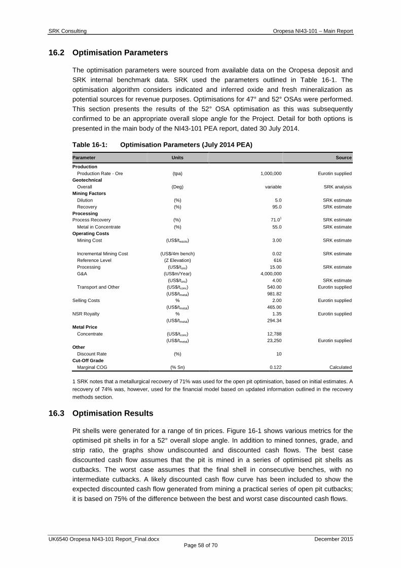
SRK Consulting Oropesa NI43-101 – Main Report
UK6540 Oropesa NI43-101 Report_Final.docx December 2015 Page 58 of 70
16.2 Optimisation Parameters
The optimisation parameters were sourced from available data on the Oropesa deposit and SRK internal benchmark data. SRK used the parameters outlined in Table 16-1. The optimisation algorithm considers indicated and inferred oxide and fresh mineralization as potential sources for revenue purposes. Optimisations for 47° and 52° OSAs were performed. This section presents the results of the 52° OSA optimisation as this was subsequently confirmed to be an appropriate overall slope angle for the Project. Detail for both options is presented in the main body of the NI43-101 PEA report, dated 30 July 2014.
Table 16-1: Optimisation Parameters (July 2014 PEA)
Parameter Units
Source
Production Production Rate - Ore (tpa) 1,000,000 Eurotin supplied
Geotechnical Overall (Deg) variable SRK analysis
Mining Factors Dilution (%) 5.0 SRK estimate Recovery (%) 95.0 SRK estimate
Processing Process Recovery (%) 71.01 SRK estimate
Metal in Concentrate (%) 55.0 SRK estimate Operating Costs
Mining Cost (US$/twaste) 3.00 SRK estimate
Incremental Mining Cost (US$/4m bench) 0.02 SRK estimate Reference Level (Z Elevation) 616 Processing (US$/tore) 15.00 SRK estimate G&A (US$m/Year) 4,000,000
(US$/tore) 4.00 SRK estimate Transport and Other (US$/tconc) 540.00 Eurotin supplied
(US$/tmetal) 981.82 Selling Costs % 2.00 Eurotin supplied
(US$/tmetal) 465.00 NSR Royalty % 1.35 Eurotin supplied
(US$/tmetal) 294.34 Metal Price
Concentrate (US$/tconc) 12,788
(US$/tmetal) 23,250 Eurotin supplied Other
Discount Rate (%) 10 Cut-Off Grade
Marginal COG (% Sn) 0.122 Calculated
1 SRK notes that a metallurgical recovery of 71% was used for the open pit optimisation, based on initial estimates. A recovery of 74% was, however, used for the financial model based on updated information outlined in the recovery methods section.
16.3 Optimisation Results
Pit shells were generated for a range of tin prices. Figure 16-1 shows various metrics for the optimised pit shells in for a 52° overall slope angle. In addition to mined tonnes, grade, and strip ratio, the graphs show undiscounted and discounted cash flows. The best case discounted cash flow assumes that the pit is mined in a series of optimised pit shells as cutbacks. The worst case assumes that the final shell in consecutive benches, with no intermediate cutbacks. A likely discounted cash flow curve has been included to show the expected discounted cash flow generated from mining a practical series of open pit cutbacks; it is based on 75% of the difference between the best and worst case discounted cash flows.
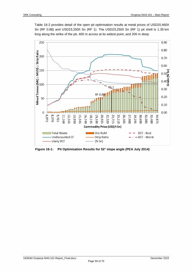
SRK Consulting Oropesa NI43-101 – Main Report
UK6540 Oropesa NI43-101 Report_Final.docx December 2015 Page 59 of 70
Table 16-2 provides detail of the open pit optimisation results at metal prices of USD20,460/t Sn (RF 0.88) and USD23,250/t Sn (RF 1). The USD23,250/t Sn (RF 1) pit shell is 1.35 km long along the strike of the pit, 400 m across at its widest point, and 200 m deep.
Figure 16-1: Pit Optimisation Results for 52° slope angle (PEA July 2014)
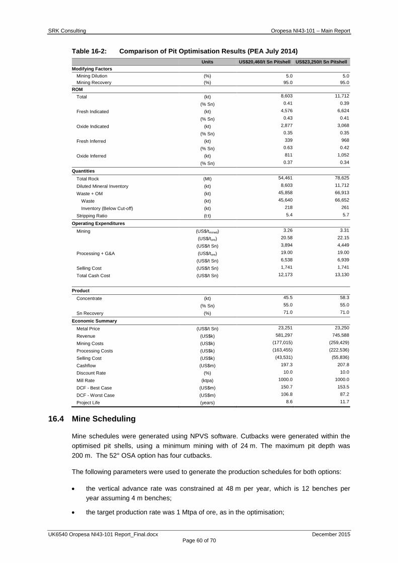
SRK Consulting Oropesa NI43-101 – Main Report
UK6540 Oropesa NI43-101 Report_Final.docx December 2015 Page 60 of 70
Table 16-2: Comparison of Pit Optimisation Results (PEA July 2014) Units US$20,460/t Sn Pitshell US$23,250/t Sn Pitshell Modifying Factors
Mining Dilution (%) 5.0 5.0 Mining Recovery (%) 95.0 95.0
ROM Total (kt) 8,603 11,712
(% Sn) 0.41 0.39
Fresh Indicated (kt) 4,576 6,624
(% Sn) 0.43 0.41
Oxide Indicated (kt) 2,877 3,068
(% Sn) 0.35 0.35
Fresh Inferred (kt) 339 968
(% Sn) 0.63 0.42
Oxide Inferred (kt) 811 1,052
(% Sn) 0.37 0.34
Quantities
Total Rock (Mt) 54,461 78,625
Diluted Mineral Inventory (kt) 8,603 11,712
Waste + OM (kt) 45,858 66,913
Waste (kt) 45,640 66,652
Inventory (Below Cut-off) (kt) 218 261
Stripping Ratio (t:t) 5.4 5.7
Operating Expenditures
Mining (US$/tmined) 3.26 3.31
(US$/tore) 20.58 22.15
(US$/t Sn) 3,894 4,449
Processing + G&A (US$/tore) 19.00 19.00
(US$/t Sn) 6,538 6,939
Selling Cost (US$/t Sn) 1,741 1,741
Total Cash Cost (US$/t Sn) 12,173 13,130
Product
Concentrate (kt) 45.5 58.3
(% Sn) 55.0 55.0
Sn Recovery (%) 71.0 71.0
Economic Summary
Metal Price (US$/t Sn) 23,251 23,250
Revenue (US$k) 581,297 745,588
Mining Costs (US$k) (177,015) (259,429)
Processing Costs (US$k) (163,455) (222,536)
Selling Cost (US$k) (43,531) (55,836)
Cashflow (US$m) 197.3 207.8
Discount Rate (%) 10.0 10.0
Mill Rate (ktpa) 1000.0 1000.0
DCF - Best Case (US$m) 150.7 153.5
DCF - Worst Case (US$m) 106.8 87.2
Project Life (years) 8.6 11.7
16.4 Mine Scheduling
Mine schedules were generated using NPVS software. Cutbacks were generated within the optimised pit shells, using a minimum mining with of 24 m. The maximum pit depth was 200 m. The 52° OSA option has four cutbacks.
The following parameters were used to generate the production schedules for both options:
• the vertical advance rate was constrained at 48 m per year, which is 12 benches per year assuming 4 m benches;
• the target production rate was 1 Mtpa of ore, as in the optimisation;
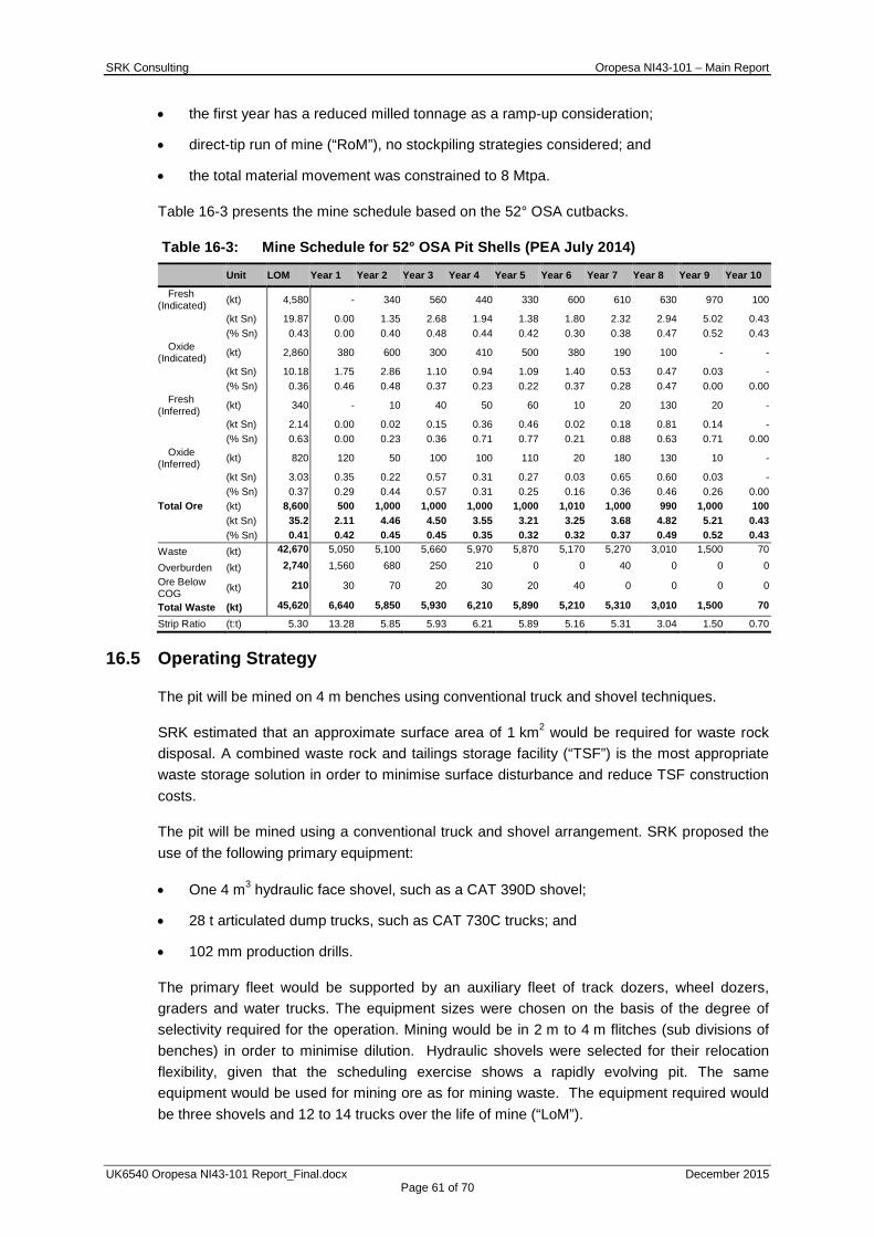
SRK Consulting Oropesa NI43-101 – Main Report
UK6540 Oropesa NI43-101 Report_Final.docx December 2015 Page 61 of 70
• the first year has a reduced milled tonnage as a ramp-up consideration;
• direct-tip run of mine (“RoM”), no stockpiling strategies considered; and
• the total material movement was constrained to 8 Mtpa.
Table 16-3 presents the mine schedule based on the 52° OSA cutbacks.
Table 16-3: Mine Schedule for 52° OSA Pit Shells (PEA July 2014)
Unit LOM Year 1 Year 2 Year 3 Year 4 Year 5 Year 6 Year 7 Year 8 Year 9 Year 10
Fresh (Indicated) (kt) 4,580 - 340 560 440 330 600 610 630 970 100
(kt Sn) 19.87 0.00 1.35 2.68 1.94 1.38 1.80 2.32 2.94 5.02 0.43
(% Sn) 0.43 0.00 0.40 0.48 0.44 0.42 0.30 0.38 0.47 0.52 0.43 Oxide
(Indicated) (kt) 2,860 380 600 300 410 500 380 190 100 - -
(kt Sn) 10.18 1.75 2.86 1.10 0.94 1.09 1.40 0.53 0.47 0.03 -
(% Sn) 0.36 0.46 0.48 0.37 0.23 0.22 0.37 0.28 0.47 0.00 0.00 Fresh
(Inferred) (kt) 340 - 10 40 50 60 10 20 130 20 -
(kt Sn) 2.14 0.00 0.02 0.15 0.36 0.46 0.02 0.18 0.81 0.14 -
(% Sn) 0.63 0.00 0.23 0.36 0.71 0.77 0.21 0.88 0.63 0.71 0.00 Oxide
(Inferred) (kt) 820 120 50 100 100 110 20 180 130 10 -
(kt Sn) 3.03 0.35 0.22 0.57 0.31 0.27 0.03 0.65 0.60 0.03 -
(% Sn) 0.37 0.29 0.44 0.57 0.31 0.25 0.16 0.36 0.46 0.26 0.00 Total Ore (kt) 8,600 500 1,000 1,000 1,000 1,000 1,010 1,000 990 1,000 100
(kt Sn) 35.2 2.11 4.46 4.50 3.55 3.21 3.25 3.68 4.82 5.21 0.43 (% Sn) 0.41 0.42 0.45 0.45 0.35 0.32 0.32 0.37 0.49 0.52 0.43 Waste (kt) 42,670 5,050 5,100 5,660 5,970 5,870 5,170 5,270 3,010 1,500 70
Overburden (kt) 2,740 1,560 680 250 210 0 0 40 0 0 0 Ore Below COG (kt) 210 30 70 20 30 20 40 0 0 0 0
Total Waste (kt) 45,620 6,640 5,850 5,930 6,210 5,890 5,210 5,310 3,010 1,500 70
Strip Ratio (t:t) 5.30 13.28 5.85 5.93 6.21 5.89 5.16 5.31 3.04 1.50 0.70
16.5 Operating Strategy
The pit will be mined on 4 m benches using conventional truck and shovel techniques.
SRK estimated that an approximate surface area of 1 km2 would be required for waste rock disposal. A combined waste rock and tailings storage facility (“TSF”) is the most appropriate waste storage solution in order to minimise surface disturbance and reduce TSF construction costs.
The pit will be mined using a conventional truck and shovel arrangement. SRK proposed the use of the following primary equipment:
• One 4 m3 hydraulic face shovel, such as a CAT 390D shovel;
• 28 t articulated dump trucks, such as CAT 730C trucks; and
• 102 mm production drills.
The primary fleet would be supported by an auxiliary fleet of track dozers, wheel dozers, graders and water trucks. The equipment sizes were chosen on the basis of the degree of selectivity required for the operation. Mining would be in 2 m to 4 m flitches (sub divisions of benches) in order to minimise dilution. Hydraulic shovels were selected for their relocation flexibility, given that the scheduling exercise shows a rapidly evolving pit. The same equipment would be used for mining ore as for mining waste. The equipment required would be three shovels and 12 to 14 trucks over the life of mine (“LoM”).
SRK Consulting Oropesa NI43-101 – Main Report
UK6540 Oropesa NI43-101 Report_Final.docx December 2015 Page 62 of 70
A summary of the projected mine labour requirement by department is presented in Table 16-4.
Table 16-4: Summary of Projected Mine Personnel (PEA July 2014) Department Personnel Mine Operations 102 Mine Maintenance 35 Technical Services 9 Total 146
16.6 Conclusions
SRK concluded the following with respect to open pit mining of the Oropesa deposit, on the basis of the 2014 MRE:
• at 1 Mtpa of mill throughput, Oropesa has a 9 to 10 year mine life;
• the average head grade is 0.41% Sn;
• the LoM strip ratio is 5.3;
• selectivity and grade control will be critical to achieving mine plan targets; and
• an overall slope angle of 52° has been supported by geotechnical investigation work and is the preferred option to be input to the financial model due to the lower stripping ratio.
16.7 Recommendations
SRK recommends the following with regard to further technical studies of the Oropesa deposit:
• an underground trade-off study to determine whether mineralisation at depth is suitable to be mined by underground methods;
• open pit optimisations that take into account a potentially more complex mineral processing flow sheet based on rock type mineralogy;
• open pit optimisations that take into account more detailed geotechnical domain information, based on further geotechnical analysis to confirm slope angles;
• open pit schedules that make provision for potential stockpiles to achieve a stable head grade; and
• detailed open pit designs in order to understand the impact of a practical design on the potentially economic mineralisation.
17 RECOVERY METHODS The information presented in this section is based on the NI43-101 PEA report by SRK, dated 30 July 2014.
SGS has developed a preliminary flowsheet for treating the Oropesa RoM material, based on the two samples tested in 2013/2014. Sample 1 (1.47% Sn) is high grade primary sulphide material and sample 2 (0.33% Sn) is low grade secondary sulphide material.
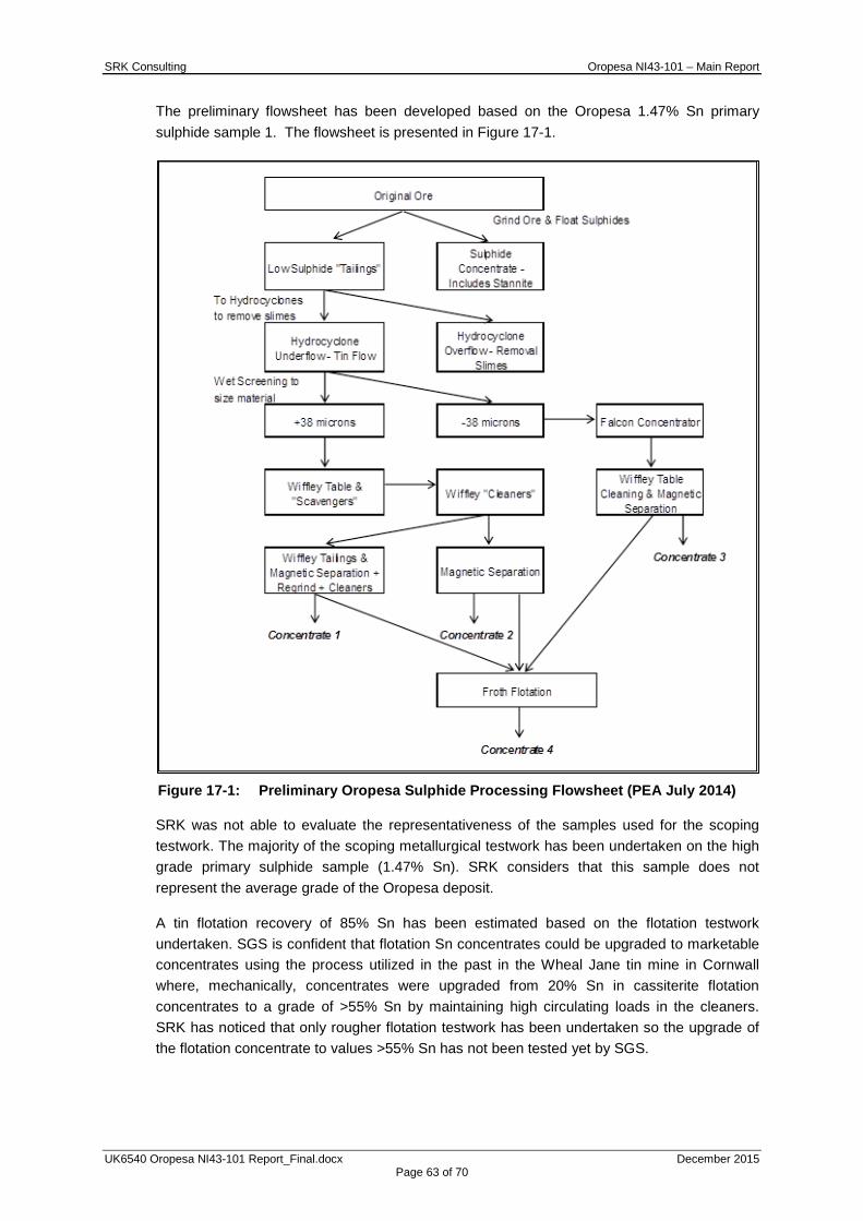
SRK Consulting Oropesa NI43-101 – Main Report
UK6540 Oropesa NI43-101 Report_Final.docx December 2015 Page 63 of 70
The preliminary flowsheet has been developed based on the Oropesa 1.47% Sn primary sulphide sample 1. The flowsheet is presented in Figure 17-1.
Figure 17-1: Preliminary Oropesa Sulphide Processing Flowsheet (PEA July 2014)
SRK was not able to evaluate the representativeness of the samples used for the scoping testwork. The majority of the scoping metallurgical testwork has been undertaken on the high grade primary sulphide sample (1.47% Sn). SRK considers that this sample does not represent the average grade of the Oropesa deposit.
A tin flotation recovery of 85% Sn has been estimated based on the flotation testwork undertaken. SGS is confident that flotation Sn concentrates could be upgraded to marketable concentrates using the process utilized in the past in the Wheal Jane tin mine in Cornwall where, mechanically, concentrates were upgraded from 20% Sn in cassiterite flotation concentrates to a grade of >55% Sn by maintaining high circulating loads in the cleaners. SRK has noticed that only rougher flotation testwork has been undertaken so the upgrade of the flotation concentrate to values >55% Sn has not been tested yet by SGS.
SRK Consulting Oropesa NI43-101 – Main Report
UK6540 Oropesa NI43-101 Report_Final.docx December 2015 Page 64 of 70
A secondary sulphide sample (0.33% Sn) is also being tested by SGS, obtaining lower Sn recoveries due to higher levels of the tin sulphide mineral stannite, the requirement of finer grinding and the increase of tin losses with the slimes. No tailings flotation testwork has been carried out on this sample. While 90% Sn recovery is considered reasonable for the tailings flotation, a figure of 85% has been used to calculate the overall tin recovery expected. The metallurgical testwork for the secondary sulphide sample is still on-going in the SGS laboratory.
Considering that the amount of oxide mineralisationis about 38% of the Oropesa deposit, SRK believes that there is a shortcoming in that no metallurgical testwork has been undertaken by the Company since 2010 for the Oropesa oxide material.
SRK recommends the following with respect to the recovery methods of the Oropesa deposit:
• carry out metallurgical testwork on samples which better represent the LoM planned grades; the samples recently used for the scoping metallurgical testwork have a grade that is too high;
• demonstrate that the process utilized in the past in the Wheal Jane tin mine in Cornwall, to upgrade Sn flotation concentrates, is applicable for the Oropesa material;
• carry out sulphide tailings flotation testwork for the secondary sulphide sample; and
• carry out more detailed metallurgical testwork for the oxide material.
18 PROJECT INFRASTRUCTURE SRK has not completed an updated analysis of the project infrastructure as part of the current study. The information presented in this section is based on the NI43-101 PEA report by SRK, dated 30 July 2014.
SRK notes that a very limited amount of infrastructure is required due to the favourable location.
SRK has not completed a detailed water supply study, but notes that there are two nearby sources of water for the Project that are considered viable. SRK also notes that it has not completed a detailed power supply study, but there are two power lines that pass close to the Project that are considered to be suitable. Capital cost provisions have been made to allow for the cost of the infrastructure required to access local power and water supplies.
SRK conducted a high level survey of TSF location options. Three sites were selected and the final selection was made based on advice from the Company. The selected site (TSF 3) is not in a valley or overlying a natural water course. For the next stage of the study, it is recommended that the following studies be undertaken to further define the Project components and confirm the assumptions made within the PEA:
• topographical survey to provide a topographical map with contours of 1 m accuracy for the preferred TSF location;
• geotechnical and geochemical testing to be undertaken on overburden and waste to determine if the material is suitable for construction;
SRK Consulting Oropesa NI43-101 – Main Report
UK6540 Oropesa NI43-101 Report_Final.docx December 2015 Page 65 of 70
• trade-off study to co-dispose tailings material and waste rock material from the open pit mining operations as there will be sufficient material of waste rock that will require an additional storage;
• land access and acquisition to be confirmed;
• the layout and interrelationships of infrastructure components to be defined for material flows and efficiencies; and
• geotechnical and hydrogeological field investigations of the in situ ground conditions within the TSF footprint.
19 MARKET STUDIES AND CONTRACTS SRK has not undertaken a market or contracts study for this report.
20 ENVIRONMENTAL STUDIES No updated environmental studies have been completed as part of the current scope of work. The information presented in this section is based on the descriptions presented in the NI43-101 PEA report by SRK, dated 30 July 2014.
The proposed Project is located in a rural environment in southern Spain in the Autonomous Region of Andalusia, approximately 110 km north east from the regional capital of Seville. The region has experienced a long history of mining activities, although unemployment levels in the area are currently high (approximately 25%). Further to a desktop review of existing information and some preliminary baseline data collection that has been undertaken for the site, the following four key environmental and social risks were identified for the Project.
• elevated arsenic concentrations in soils and groundwater need to be characterised to understand any potential liability;
• high expectations around job creation need to be managed through adequate stakeholder engagement and training to maximise employment of local people;
• economic and/or physical displacement of farmsteads and or subsistence lands may require some time to negotiate agreements with farmers; although current good relations with landowners suggest that this should not have scheduling implications; and
• the location of the Project site within a legally recognised area of conservation significance requires that potential impacts are clearly understood and the necessary permits obtained. Based on the Company’s discussions with government this is not considered to pose any significant delays to the Project;
All of the key environmental and social risks identified are considered to be manageable within the next stage of Project development and are not expected to pose material risks to the Project either in terms of material delays or significant cost implications.
21 CAPITAL AND OPERATING COSTS No updated assessment of capital and operating costs has been completed as part of the current study. The information presented in this section is based on the NI43-101 PEA report by SRK, dated 30 July 2014.

SRK Consulting Oropesa NI43-101 – Main Report
UK6540 Oropesa NI43-101 Report_Final.docx December 2015 Page 66 of 70
SRK estimated the costs appropriately for a PEA. The results are presented in Table 21-1 and Table 21-2 were used as inputs to the economic analysis.
Table 21-1: Capital Cost Summary (PEA July 2014)
Item Value
Mining Equipment USDM 23.0 Processing Plant USDM 55.0 Tailings Storage Facility USDM 22.4 Miscellaneous USDM 6.0
Table 21-2: Operating Cost Summary (PEA July 2014)
Item Value
Mining Cost USD/t expit 3.76 Processing USD/t milled 12.00 G&A USD/t milled 2.69 Selling Costs USD/t Sn 1,299.00
22 ECONOMIC ANALYSIS No updated economic analysis has been completed as part of the current study. The information presented in this section is based on the NI43-101 PEA report by SRK, dated 30 July 2014.
Based on the scoping level work undertaken, SRK concluded the following with respect to the economic model:
• the Project is economically viable at the two metal price scenarios of USD23,250/t and USD27,000/t;
• the Project generates positive cash flow starting in Year 3, based on an 18-month project implementation timeline;
• the Project’s payback is five years for the USD27,000/t scenario and 8 years for the USD23,250/t scenario.
• the value of the Project is most sensitive to changes in commodity price; and
• the value of the Project is least sensitive to changes in capital expenditure.
Table 22-1 provides the results of the economic analysis at a metal price of USD27,000/t Sn.
Table 22-1: Summary of Economic Model Results at USD27,000/t Sn (PEA July 2014)
Discount Rate
NPV USDm NPV USDm
Post Tax Pre Tax Net Present Value 0.0% 163 211
5.0% 99 134
7.5% 73 105
8.0% 69 100
10.0% 54 81
15.0% 23 44
Internal Rate of Return IRR 20.2% 24.4%
SRK recommends the following:
• future drilling should focus on the high grade areas to enhance the Project economics;
• the economic impact of contractor mining should be examined, based on detailed quotes from local contractors;
SRK Consulting Oropesa NI43-101 – Main Report
UK6540 Oropesa NI43-101 Report_Final.docx December 2015 Page 67 of 70
• examine higher production rates to improve economics in future iterations of the Project;
• additional mine scheduling with the intent to smooth head grades and bring higher grades forward in time;
• smelter terms and transport charges should be detailed further; and
• a tin marketing study be undertaken as part of future technical studies.
23 ADJACENT PROPERTIES SRK is not aware of any properties adjacent to Oropesa.
24 OTHER RELEVANT DATA AND INFORMATION The information presented in this section is based on the NI43-101 PEA report by SRK, dated 30 July 2014.
24.1 Geotechnics
For optimisation purposes, pit slopes should not exceed 52° for both 150 and 200 m deep pits. This study did not include any information related to the structures orientation. Orientation data are necessary for kinematics analyses in order to determine the potential for planar, toppling and wedge failures on a bench scale and therefore give a detailed bench and berm configuration. A more detailed geotechnical investigation programme would be required for a PFS including:
• drilling of orientated borehole core;
• determination of groundwater conditions;
• detailed geotechnical logging of the core;
• laboratory strength testing of selected core samples.;
• development of a geotechnical domain model; and
• undertaking more detailed rock mass and kinematic stability analysis.
24.2 Hydrogeology
Hydrogeological characterisation has been based on the environmental permitting study conducted by PGMA, SLP (PGMA, 2012) which is intended to complement an Environmental Impact Study. It is evident that PGMA has undertaken a programme of hydrogeological fieldwork, including:
• construction of monitoring wells;
• sampling of groundwater; and
• measurement of groundwater levels.
Only summary details of the hydrogeological study were made available to SRK. The groundwater flow direction appears to be structurally controlled where the groundwater contours are approximately parallel to mapped structures (regional groundwater flow direction has not been ascertained).
SRK Consulting Oropesa NI43-101 – Main Report
UK6540 Oropesa NI43-101 Report_Final.docx December 2015 Page 68 of 70
24.3 Environmental Geochemistry
The data and information currently available for an environmental geochemistry assessment is limited; however, preliminary evaluation of potential risks have been conducted and are summarised as follows:
• Presence of sulphide minerals. Oropesa is a hard rock sulphide deposit. The pit walls and associated waste rock are likely to include exposed sulfidic minerals, including pyrite, pyrrhotite and arsenopyrite. There is therefore a potential for acid generation as a result of sulphide oxidation. This may impact contact waters flushing the pit walls, waste rock dumps and also the tailings facility. The high sulphide tailings from the potential flotation products could be particularly problematic.
• Lack of acid-buffering carbonate minerals. The mineralogy of the resource reports a lack of substantial carbonate presence to act as a buffer against acid release and low pH contact waters. Siderite may be present in moderate quantities; however, even though a carbonate mineral, siderite offers negligible potential for acid neutralisation.
• Solute mobilisation. Formation of low pH contact waters would likely lead to the associated release of metal and metalloid species such as iron, manganese and arsenic and elevated solute loading, primarily from sulphate release.
• Baseline groundwater monitoring. Water quality monitoring has been completed for a limited number of groundwater locations. Sample data report circum-neutral waters, often with elevated arsenic concentrations. This suggests that the baseline water quality conditions in the project area may be relatively poor due to the nature of the mineralisation. Elevated concentrations of iron and manganese may be indicative of particulate matter and/or anoxic conditions.
Overall, given the abundance of sulphide minerals and the inherent propensity for acid rock drainage and metal leaching (“ARDML”) solute release, and the naturally elevated arsenic concentrations in groundwater, it is likely that if unmanaged the discharge of mine contact waters could adversely impact upon the environment and local receptors.
SRK recommends undertaking a programme of testing for ARDML assessment, and to expand the water quality monitoring programme to collect more data for a wider range of parameters. Following the data collection, the potential for impacts to water quality should be assessed and mitigation strategies developed.
25 INTERPRETATIONS AND CONCLUSIONS The Oropesa deposit is an open pit mining target which is at a relatively advanced stage of drilling and geological understanding. This resource estimate suggests there is a significant body of mineralisation which occurs within 265 m of surface; however, more work is required to confirm this and to fully evaluate the potential for a mining project.
The improved geological interpretation used to generate the model for the 2015 Mineral Resource estimate is generally considered to be robust; however, there are areas of lower geological confidence which may be subject to further revision in the future. SRK considers the exploration data accumulated by the Company is generally reliable and suitable for the purpose of this Mineral Resource estimate.
SRK Consulting Oropesa NI43-101 – Main Report
UK6540 Oropesa NI43-101 Report_Final.docx December 2015 Page 69 of 70
The economic viability of the Oropesa Project will need to be fully addressed in further technical studies.
26 RECOMMENDATIONS SRK considers there to be good potential to improve confidence and increase tonnage in the reported Mineral Resource at Oropesa with further modelling work and additional drilling. In relation to drilling and sampling, SRK would recommend the following:
• Infill drilling to add geological confidence to convert the Inferred Resources to Indicated and convert some of the Indicated to Measured Resources. SRK has not proposed a detailed infill drilling program, however considers a budget in the order of magnitude of USD10m (to double the drilling completed to date) should achieve this.
• Complete additional exploration drilling along strike and around the margins of the deposit where there is potential to add additional replacement-style and/or fault-controlled mineralisation. Any future drilling should include the systematic collection of downhole structural data to further constrain the geological model.
• Furthermore, the updated geological model used to guide the development of the mineralisation wireframes has significant implications for exploration in the surrounding area. The geological model should be further tested and refined in conjunction with a reassessment of the licence scale exploration potential.
• Complete further metallurgical testwork to improve the current understanding of the potential process recovery for tin, which impacts on the technical parameters used for reporting of the Oropesa Mineral Resource.
In relation to further modelling work, SRK would recommend modelling the lower grade material (between 0.1 – 0.25% Sn) that occurs in certain areas adjacent to the current Resource model which would add marginal material to the Resource.
In addition, SRK would also recommend the following:
• Update the July 2014 PEA on the basis of the updated Mineral Resource Estimate.
• Adopt a commercial database system to improve the overall database management at Oropesa.
• For the holes drilled prior to ORPD059 (if available) SRK recommend to send pulp splits from a representative portion of samples to the primary laboratory along with QAQC samples according to the current protocols to compare the laboratory performance today with its performance in 2011 and 2010 prior to drillhole ORPD059.
27 REFERENCES Dallmeyer, R.D. and Martinez Garcia, E. (Eds), 1990. Pre-Mesozoic geology of Iberia. Springer Verlag. 416p.
Hosking, K.F.G., 1988. The world’s major types of tin deposits. In: Hutchison, C.S. (ed), Geology of tin deposits in Asia and the Pacific, pp 3-49.
Miller, 2015. Estimation of the maximum tin recovery at the Oropesa Tin Project. Internal memorandum for Eurotin Inc.

SRK Consulting Oropesa NI43-101 – Main Report
UK6540 Oropesa NI43-101 Report_Final.docx December 2015 Page 70 of 70
Smith, J. A., 2012. Characterising the nature of cassiterite and associated mineralisation at the Oropesa Tin Deposit, SW Spain. MSc Thesis, University of Exeter, 210p.
SRK, 2012. Mineral Resource Estimate of the Oropesa Tin Project, Cordoba Province, Spain. Technical report prepared for Minas De Estaño De España, SLU.
SRK, 2014. Updated Mineral Resource Estimate of the Oropesa Tin Project, Cordoba Province, Spain, June 2014. Technical report prepared for Minas De Estaño De España, SLU.
SRK, 2014. A preliminary Economic Assesment/Scoping Study of the Oropesa Tin Deposit. Technical report prepared for Eurotin Inc.
Taylor, R.G., 1979. Geology of tin deposits; Elsevier Scientific Publishing Company, 543p.
Taylor, R .G., 2011. Petrology of 14 drill core samples from the Oropesa tin field. Private report, Eurotin 37p
Taylor, R.G., 2011a. Geological aspects and overview potential of the Oropesa Tin field. Consultancy report, May, 2011.
Taylor, R.G., 2011b. Structural aspects concerning the Oropesa tin system. Consultancy report, October 2011.
Taylor, R.G., 2011c. Petrological examination of 4 gossanous samples from the Oropesa tin prospect, Spain. Consultancy report, November, 2011.
Wagner, R.H., 2004. The Iberian Massif: a Carboniferous assembly. Journal of Iberian Geology 30, 93-108.
For and on behalf of SRK Consulting (UK) Limited
Paul Stenhouse, Senior Consultant (Structural Geology), Project Manager SRK Consulting (UK) Limited
Mike Beare, Corporate Consultant (Mining Engineering), Project Director SRK Consulting (UK) Limited
Martin Pittuck, Corporate Consultant (Resource Geology), SRK Consulting (UK) Limited

SRK Consulting Oropesa NI43-101 – Technical Appendix A
UK6540 Oropesa NI43-101 Report_Final.docx December 2015 Page A1 of A7
APPENDIX
A QAQC ANALYSIS
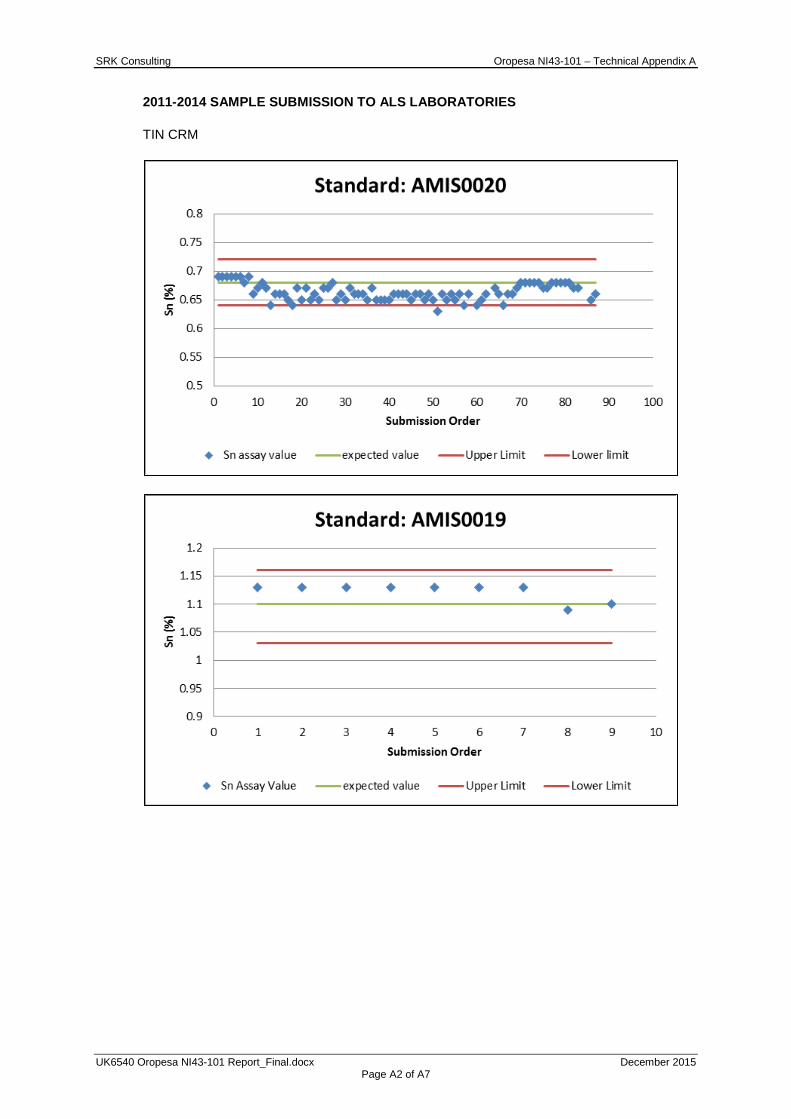
SRK Consulting Oropesa NI43-101 – Technical Appendix A
UK6540 Oropesa NI43-101 Report_Final.docx December 2015 Page A2 of A7
2011-2014 SAMPLE SUBMISSION TO ALS LABORATORIES
TIN CRM

SRK Consulting Oropesa NI43-101 – Technical Appendix A
UK6540 Oropesa NI43-101 Report_Final.docx December 2015 Page A3 of A7
TIN CRM (ALS INTERNAL)
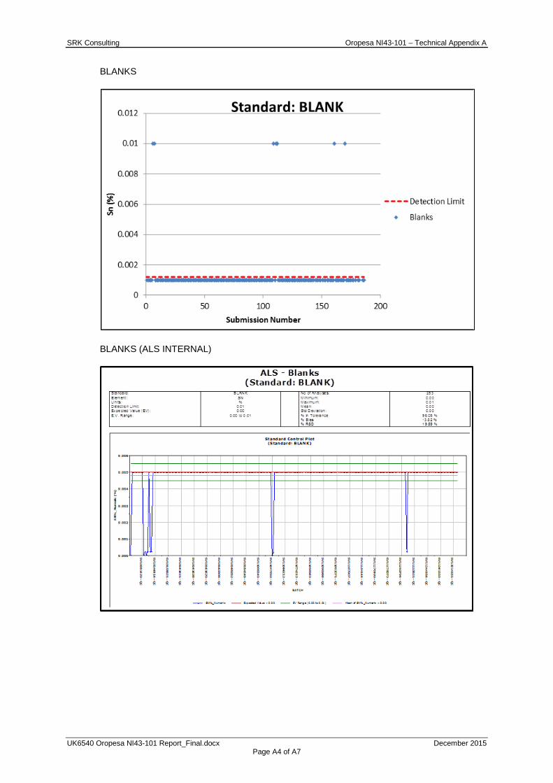
SRK Consulting Oropesa NI43-101 – Technical Appendix A
UK6540 Oropesa NI43-101 Report_Final.docx December 2015 Page A4 of A7
BLANKS
BLANKS (ALS INTERNAL)
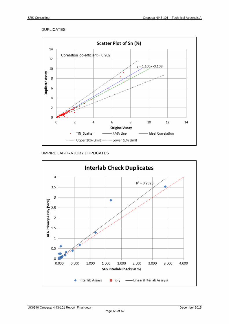
SRK Consulting Oropesa NI43-101 – Technical Appendix A
UK6540 Oropesa NI43-101 Report_Final.docx December 2015 Page A5 of A7
DUPLICATES
UMPIRE LABORATORY DUPLICATES
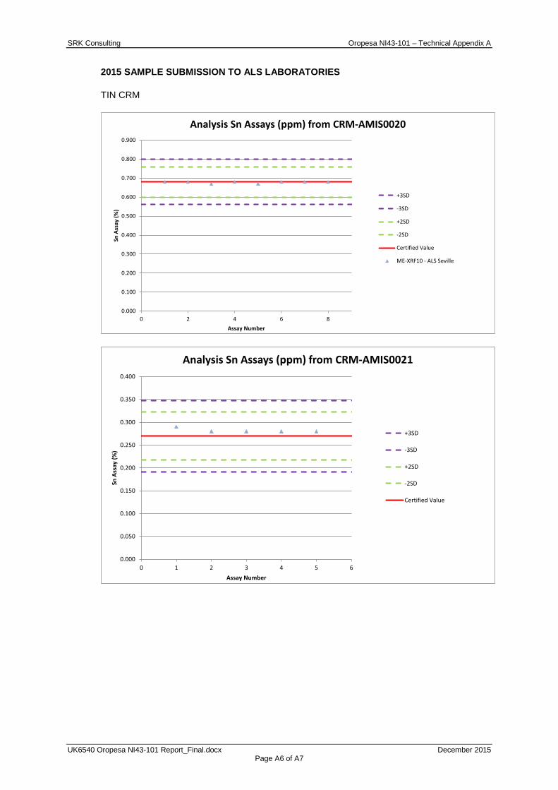
SRK Consulting Oropesa NI43-101 – Technical Appendix A
UK6540 Oropesa NI43-101 Report_Final.docx December 2015 Page A6 of A7
2015 SAMPLE SUBMISSION TO ALS LABORATORIES
TIN CRM
0.000
0.100
0.200
0.300
0.400
0.500
0.600
0.700
0.800
0.900
0 2 4 6 8
Sn A
ssay
(%)
Assay Number
Analysis Sn Assays (ppm) from CRM-AMIS0020
+3SD
-3SD
+2SD
-2SD
Certified Value
ME-XRF10 - ALS Seville
0.000
0.050
0.100
0.150
0.200
0.250
0.300
0.350
0.400
0 1 2 3 4 5 6
Sn A
ssay
(%)
Assay Number
Analysis Sn Assays (ppm) from CRM-AMIS0021
+3SD
-3SD
+2SD
-2SD
Certified Value
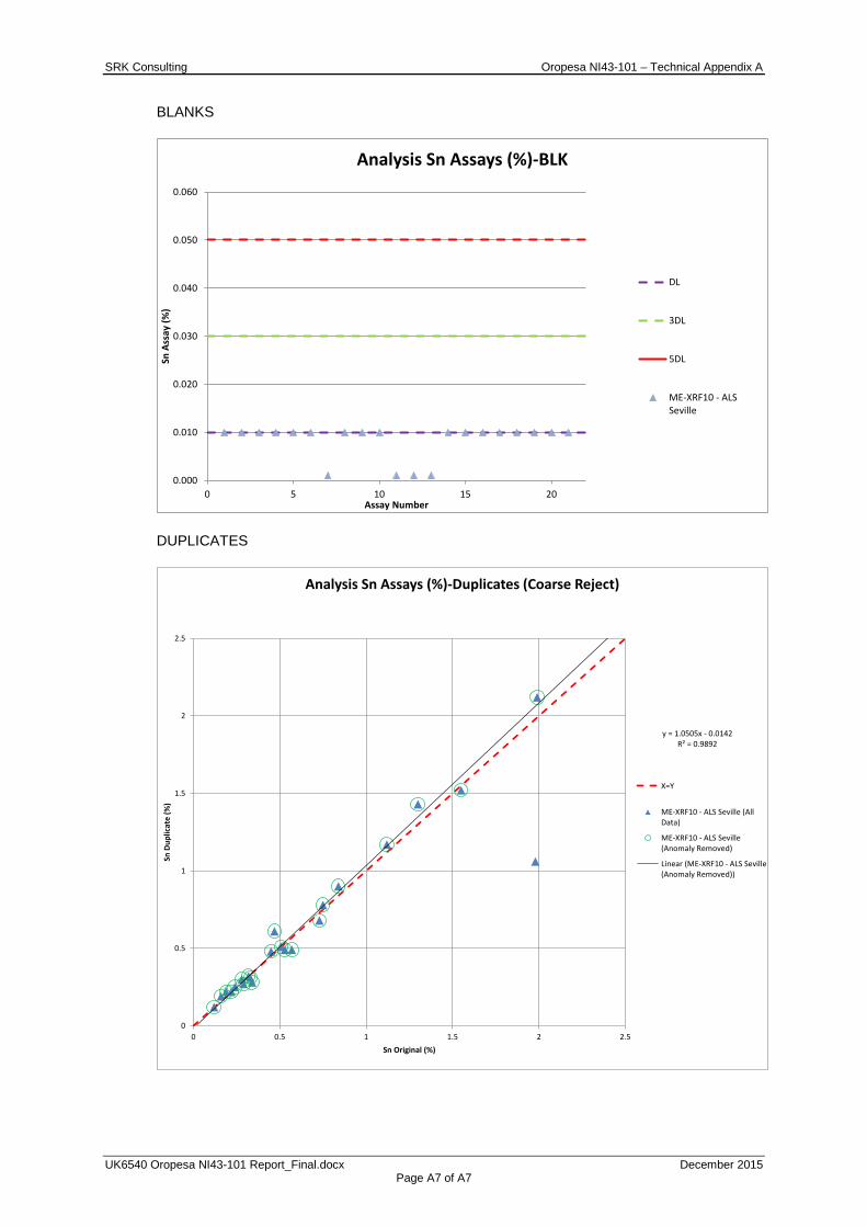
SRK Consulting Oropesa NI43-101 – Technical Appendix A
UK6540 Oropesa NI43-101 Report_Final.docx December 2015 Page A7 of A7
BLANKS
DUPLICATES
0.000
0.010
0.020
0.030
0.040
0.050
0.060
0 5 10 15 20
Sn A
ssay
(%)
Assay Number
Analysis Sn Assays (%)-BLK
DL
3DL
5DL
ME-XRF10 - ALSSeville
y = 1.0505x - 0.0142R² = 0.9892
0
0.5
1
1.5
2
2.5
0 0.5 1 1.5 2 2.5
Sn D
uplic
ate
(%)
Sn Original (%)
Analysis Sn Assays (%)-Duplicates (Coarse Reject)
X=Y
ME-XRF10 - ALS Seville (AllData)
ME-XRF10 - ALS Seville(Anomaly Removed)
Linear (ME-XRF10 - ALS Seville(Anomaly Removed))
SRK Consulting Oropesa NI43-101 – Technical Appendix B
UK6540 Oropesa NI43-101 Report_Final.docx December 2015 Page B1 of B4
APPENDIX
B HISTOGRAMS AND LOG PROBABILITY PLOTS
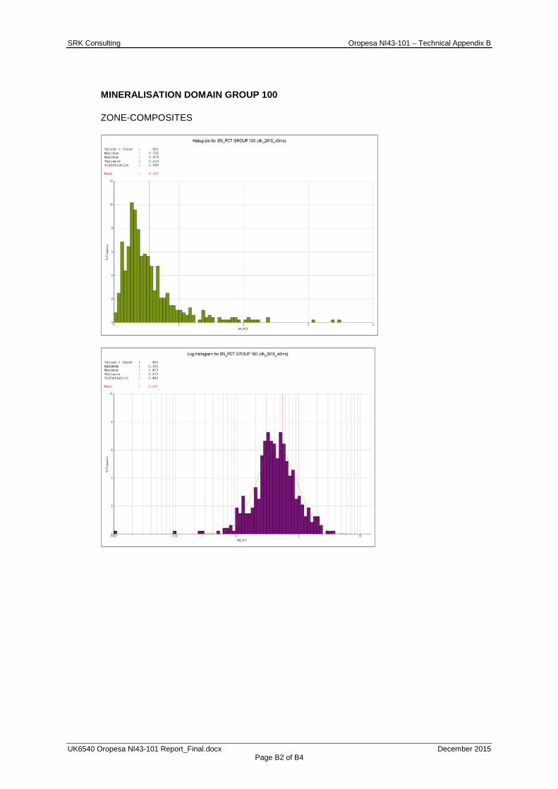
SRK Consulting Oropesa NI43-101 – Technical Appendix B
UK6540 Oropesa NI43-101 Report_Final.docx December 2015 Page B2 of B4
MINERALISATION DOMAIN GROUP 100
ZONE-COMPOSITES

SRK Consulting Oropesa NI43-101 – Technical Appendix B
UK6540 Oropesa NI43-101 Report_Final.docx December 2015 Page B3 of B4
2M COMPOSITES
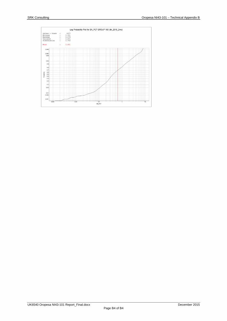
SRK Consulting Oropesa NI43-101 – Technical Appendix B
UK6540 Oropesa NI43-101 Report_Final.docx December 2015 Page B4 of B4

SRK Consulting Oropesa NI43-101 – Technical Appendix C
UK6540 Oropesa NI43-101 Report_Final.docx December 2015 C1of C3
APPENDIX
C BLOCK GRADE VISUAL VALIDATION
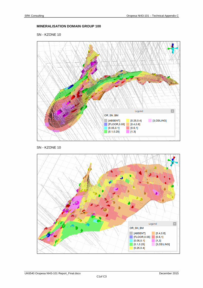
SRK Consulting Oropesa NI43-101 – Technical Appendix C
UK6540 Oropesa NI43-101 Report_Final.docx December 2015 C1of C3
MINERALISATION DOMAIN GROUP 100
SN - KZONE 10
SN - KZONE 10
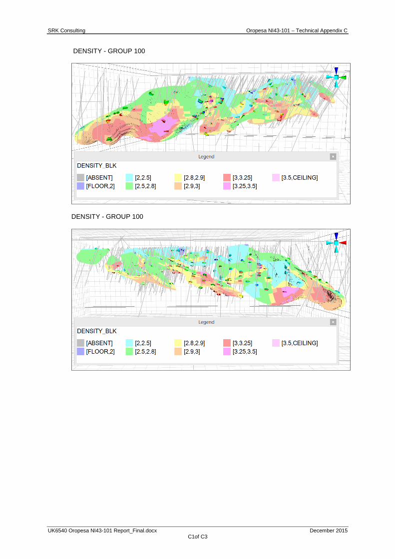
SRK Consulting Oropesa NI43-101 – Technical Appendix C
UK6540 Oropesa NI43-101 Report_Final.docx December 2015 C1of C3
DENSITY - GROUP 100
DENSITY - GROUP 100

SRK Consulting Oropesa NI43-101 – Technical Appendix D
UK6540 Oropesa NI43-101 Report_Final.docx December 2015 Page D1 of D6
APPENDIX
D VALIDATION PLOTS
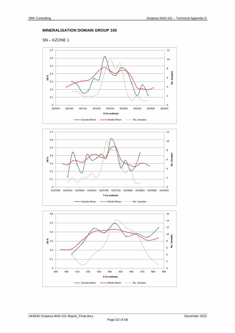
SRK Consulting Oropesa NI43-101 – Technical Appendix D
UK6540 Oropesa NI43-101 Report_Final.docx December 2015 Page D2 of D6
MINERALISATION DOMAIN GROUP 100
SN – KZONE 1
0
2
4
6
8
10
12
0
0.1
0.2
0.3
0.4
0.5
0.6
0.7
283050 283100 283150 283200 283250 283300 283350 283400 283450
No.
Sam
ples
SN %
X-Co-ordinate
Sample Mean Model Mean No. Samples
0
2
4
6
8
10
12
0
0.1
0.2
0.3
0.4
0.5
0.6
0.7
4243500 4243550 4243600 4243650 4243700 4243750 4243800 4243850 4243900 4243950
No.
Sam
ples
SN %
Y Co-ordinate
Sample Mean Model Mean No. Samples
0
2
4
6
8
10
12
14
16
0
0.1
0.2
0.3
0.4
0.5
0.6
390 400 410 420 430 440 450 460 470 480 490
No.
Sam
ples
SN %
Z Co-ordinate
Sample Mean Model Mean No. Samples
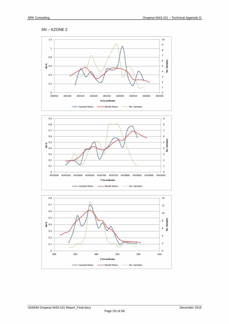
SRK Consulting Oropesa NI43-101 – Technical Appendix D
UK6540 Oropesa NI43-101 Report_Final.docx December 2015 Page D3 of D6
SN – KZONE 2
0
1
2
3
4
5
6
7
8
9
10
0
0.2
0.4
0.6
0.8
1
1.2
283050 283100 283150 283200 283250 283300 283350 283400 283450
No.
Sam
ples
SN %
X-Co-ordinate
Sample Mean Model Mean No. Samples
0
1
2
3
4
5
6
7
8
9
0
0.1
0.2
0.3
0.4
0.5
0.6
0.7
0.8
0.9
4243500 4243550 4243600 4243650 4243700 4243750 4243800 4243850 4243900 4243950
No.
Sam
ples
SN %
Y Co-ordinate
Sample Mean Model Mean No. Samples
0
2
4
6
8
10
12
14
0
0.1
0.2
0.3
0.4
0.5
0.6
0.7
0.8
380 430 480 530 580 630
No.
Sam
ples
SN %
Z Co-ordinate
Sample Mean Model Mean No. Samples
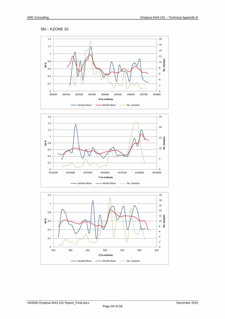
SRK Consulting Oropesa NI43-101 – Technical Appendix D
UK6540 Oropesa NI43-101 Report_Final.docx December 2015 Page D4 of D6
SN – KZONE 10
0
2
4
6
8
10
12
14
16
18
0
0.2
0.4
0.6
0.8
1
1.2
1.4
283000 283100 283200 283300 283400 283500 283600 283700 283800
No.
Sam
ples
SN %
X-Co-ordinate
Sample Mean Model Mean No. Samples
0
5
10
15
20
25
0
0.2
0.4
0.6
0.8
1
1.2
1.4
1.6
4243300 4243400 4243500 4243600 4243700 4243800 4243900
No.
Sam
ples
SN %
Y Co-ordinate
Sample Mean Model Mean No. Samples
0
2
4
6
8
10
12
14
16
18
20
0
0.2
0.4
0.6
0.8
1
1.2
350 400 450 500 550 600 650
No.
Sam
ples
SN %
Z Co-ordinate
Sample Mean Model Mean No. Samples
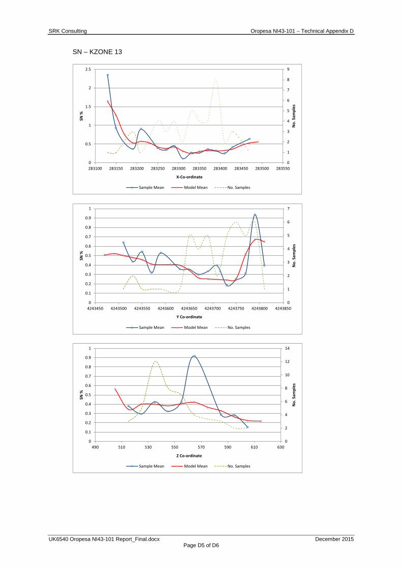
SRK Consulting Oropesa NI43-101 – Technical Appendix D
UK6540 Oropesa NI43-101 Report_Final.docx December 2015 Page D5 of D6
SN – KZONE 13
0
1
2
3
4
5
6
7
8
9
0
0.5
1
1.5
2
2.5
283100 283150 283200 283250 283300 283350 283400 283450 283500 283550
No.
Sam
ples
SN %
X-Co-ordinate
Sample Mean Model Mean No. Samples
0
1
2
3
4
5
6
7
0
0.1
0.2
0.3
0.4
0.5
0.6
0.7
0.8
0.9
1
4243450 4243500 4243550 4243600 4243650 4243700 4243750 4243800 4243850
No.
Sam
ples
SN %
Y Co-ordinate
Sample Mean Model Mean No. Samples
0
2
4
6
8
10
12
14
0
0.1
0.2
0.3
0.4
0.5
0.6
0.7
0.8
0.9
1
490 510 530 550 570 590 610 630
No.
Sam
ples
SN %
Z Co-ordinate
Sample Mean Model Mean No. Samples
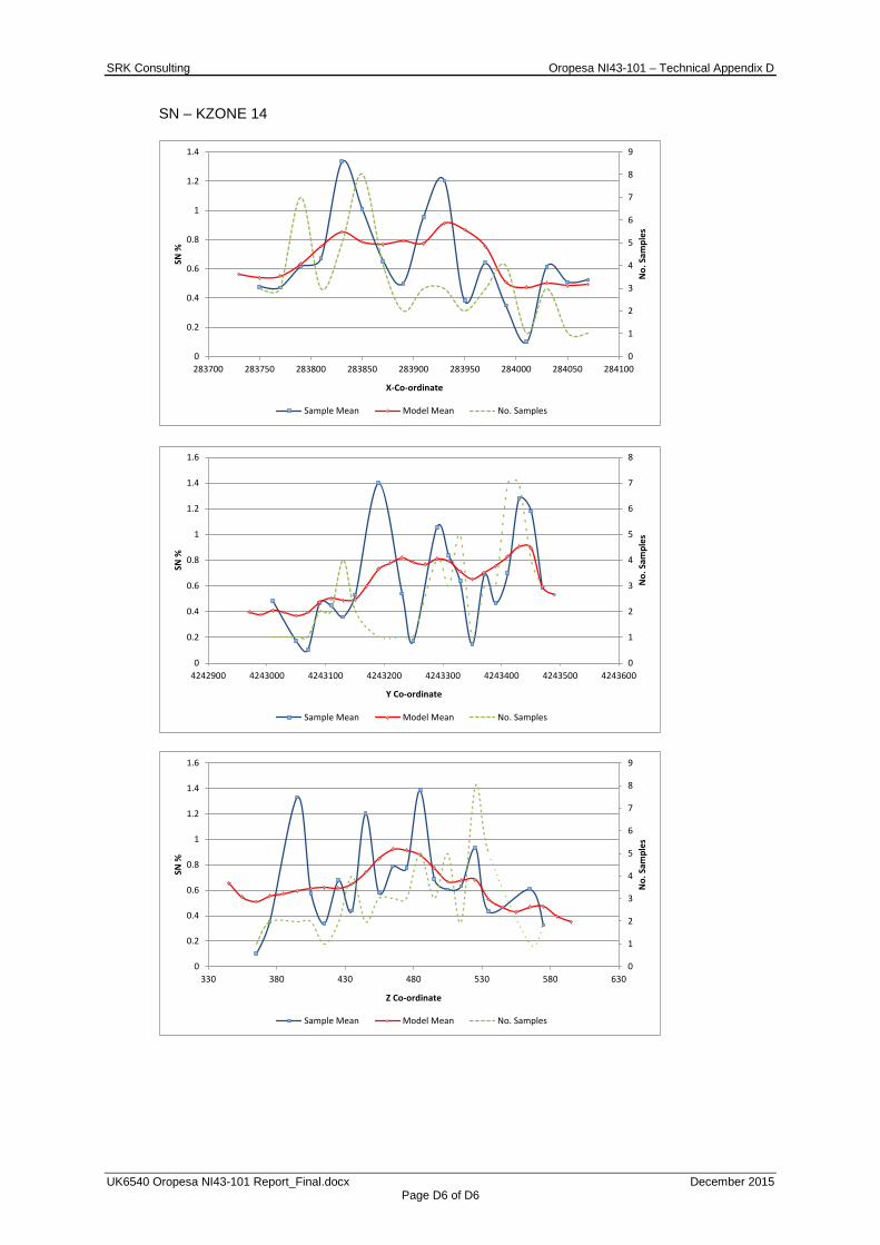
SRK Consulting Oropesa NI43-101 – Technical Appendix D
UK6540 Oropesa NI43-101 Report_Final.docx December 2015 Page D6 of D6
SN – KZONE 14
0
1
2
3
4
5
6
7
8
9
0
0.2
0.4
0.6
0.8
1
1.2
1.4
283700 283750 283800 283850 283900 283950 284000 284050 284100
No.
Sam
ples
SN %
X-Co-ordinate
Sample Mean Model Mean No. Samples
0
1
2
3
4
5
6
7
8
0
0.2
0.4
0.6
0.8
1
1.2
1.4
1.6
4242900 4243000 4243100 4243200 4243300 4243400 4243500 4243600
No.
Sam
ples
SN %
Y Co-ordinate
Sample Mean Model Mean No. Samples
0
1
2
3
4
5
6
7
8
9
0
0.2
0.4
0.6
0.8
1
1.2
1.4
1.6
330 380 430 480 530 580 630
No.
Sam
ples
SN %
Z Co-ordinate
Sample Mean Model Mean No. Samples

SRK Consulting Oropesa NI43-101 – Technical Appendix E
UK6540 Oropesa NI43-101 Report_Final.docx December 2015 Page E1 of E3
APPENDIX
E VERTICAL PROFILE ANALYSIS

SRK Consulting Oropesa NI43-101 – Technical Appendix E
UK6540 Oropesa NI43-101 Report_Final.docx December 2015 Page E2 of E3
Vertical Profile Analysis for the Oropesa Project above a 0.1% Sn cut-off
Elevation (m RL) Indicated Inferred
Tonnes (kt) Tin Tonnes (kt) Tin % Sn Metal (Sn t) % Sn Metal (Sn t)
>620 - - - 4 1 20 610 to 620 12 0.71 85 55 0.50 275 600 to 610 58 0.63 370 86 0.46 395 590 to 600 118 0.56 660 112 0.43 480 580 to 590 139 0.59 815 121 0.44 525 570 to 580 163 0.57 940 130 0.47 605 560 to 570 190 0.57 1,090 136 0.50 675 550 to 560 320 0.51 1,625 146 0.51 750 540 to 550 414 0.48 2,010 158 0.53 835 530 to 540 476 0.54 2,550 134 0.55 735 520 to 530 617 0.66 4,070 137 0.50 680 510 to 520 616 0.71 4,370 132 0.47 615 500 to 510 592 0.57 3,360 138 0.43 600 490 to 500 530 0.52 2,755 155 0.51 790 480 to 490 481 0.57 2,735 182 0.65 1,190 470 to 480 531 0.57 3,045 106 0.40 430 460 to 470 533 0.55 2,935 117 0.41 480 450 to 460 600 0.53 3,160 182 0.46 835 440 to 450 682 0.52 3,530 166 0.50 835 430 to 440 598 0.50 3,000 223 0.51 1,130 420 to 430 395 0.48 1,875 110 0.59 650 410 to 420 281 0.49 1,385 95 0.63 605 400 to 410 328 0.49 1,620 102 0.63 640 390 to 400 322 0.55 1,775 96 0.61 580 380 to 390 216 0.59 1,275 88 0.61 540 370 to 380 140 0.53 740 97 0.63 610 360 to 370 73 0.41 300 102 0.57 580 350 to 360 21 0.34 75 53 0.63 335 340 to 350 - - - 15 1 100
Vertical Profile Analysis for the Oropesa Project above a 0.2% Sn cut-off
Elevation (m RL) Indicated Inferred
Tonnes (kt) Tin Tonnes (kt) Tin % Sn Metal (Sn t) % Sn Metal (Sn t)
>620 - - - 4 1 20 610 to 620 10 0.80 80 52 0.52 270 600 to 610 37 0.92 340 79 0.48 380 590 to 600 93 0.67 625 106 0.44 470 580 to 590 116 0.67 780 113 0.45 510 570 to 580 135 0.66 895 123 0.48 595 560 to 570 174 0.61 1,065 131 0.51 665 550 to 560 302 0.53 1,600 141 0.53 740 540 to 550 398 0.50 1,985 157 0.53 835 530 to 540 462 0.55 2,530 132 0.55 730 520 to 530 613 0.66 4,065 137 0.50 680 510 to 520 612 0.71 4,365 132 0.47 615 500 to 510 586 0.57 3,345 138 0.43 600 490 to 500 521 0.53 2,740 155 0.51 790 480 to 490 471 0.58 2,720 182 0.65 1,190 470 to 480 524 0.58 3,035 106 0.40 430 460 to 470 515 0.56 2,905 116 0.41 480 450 to 460 585 0.54 3,135 182 0.46 835 440 to 450 682 0.52 3,530 166 0.50 835 430 to 440 598 0.50 3,000 223 0.51 1,130 420 to 430 395 0.48 1,875 110 0.59 650 410 to 420 276 0.50 1,380 95 0.63 605 400 to 410 301 0.52 1,570 102 0.63 640 390 to 400 306 0.57 1,745 96 0.61 580 380 to 390 216 0.59 1,275 88 0.61 540 370 to 380 140 0.53 740 97 0.63 610 360 to 370 73 0.41 300 102 0.57 580 350 to 360 21 0.34 75 53 0.63 335 340 to 350 - - - 15 1 100

SRK Consulting Oropesa NI43-101 – Technical Appendix E
UK6540 Oropesa NI43-101 Report_Final.docx December 2015 Page E3 of E3
Vertical Profile Analysis for the Oropesa Project above a 0.25% Sn cut-off
Elevation (m RL) Indicated Inferred
Tonnes (kt) Tin Tonnes (kt) Tin % Sn Metal (Sn t) % Sn Metal (Sn t)
>620 - - - 4 1 20 610 to 620 10 0.81 80 50 0.53 270 600 to 610 33 1.00 330 76 0.49 375 590 to 600 85 0.72 610 96 0.47 445 580 to 590 112 0.69 770 102 0.48 490 570 to 580 133 0.67 890 107 0.52 555 560 to 570 162 0.64 1,040 114 0.55 630 550 to 560 296 0.54 1,585 125 0.57 705 540 to 550 398 0.50 1,985 136 0.58 785 530 to 540 451 0.55 2,505 119 0.59 700 520 to 530 604 0.67 4,045 130 0.51 665 510 to 520 594 0.73 4,320 132 0.47 615 500 to 510 565 0.58 3,295 138 0.43 600 490 to 500 511 0.53 2,720 155 0.51 790 480 to 490 468 0.58 2,710 182 0.65 1,190 470 to 480 506 0.59 2,995 104 0.41 425 460 to 470 503 0.57 2,880 116 0.41 480 450 to 460 568 0.55 3,100 182 0.46 835 440 to 450 660 0.53 3,480 161 0.51 825 430 to 440 587 0.51 2,970 223 0.51 1,130 420 to 430 391 0.48 1,865 110 0.59 650 410 to 420 266 0.51 1,355 95 0.63 605 400 to 410 263 0.57 1,485 102 0.63 640 390 to 400 288 0.59 1,705 96 0.61 580 380 to 390 216 0.59 1,275 88 0.61 540 370 to 380 140 0.53 740 97 0.63 610 360 to 370 68 0.42 285 94 0.60 560 350 to 360 20 0.35 70 52 0.63 330 340 to 350 - - - 15 1 100

SRK Consulting Oropesa NI43-101 – Technical Appendix F
UK6540 Oropesa NI43-101 Report_Final.docx December 2015 Page F1 of F3
APPENDIX
F CERTIFICATES OF QUALIFIED PERSONS
SRK Consulting Oropesa NI43-101 – Technical Appendix F
UK6540 Oropesa NI43-101 Report_Final.docx December 2015 Page F2 of F3
CERTIFICATE OF QUALIFIED PERSON Martin Pittuck
I, Martin Frank Pittuck, MSc., C.Eng, MIMMM do hereby certify that:
1. I am Corporate Consultant (Mining Geology) of SRK Consulting (UK) Limited with an office at 5th Floor, Churchill House, Churchill Way, Cardiff CF10 2HH, United Kingdom.
2. This certificate applies to the technical report with an effective date of October 30, 2015 and titled “NI 43-101 Technical Report on a Mineral Resource estimate on the Oropesa tin project, Cordoba, Spain, October 30 2015” (the “Technical Report”).
3. I am a graduate with a Master of Science in Mineral Resources gained from Cardiff College, University of Wales in 1996 and I have practised my profession continuously since that time. Since graduating I have worked as a consultant at SRK on a wide range of mineral projects, specializing in precious and rare metals. I have undertaken many geological investigations, resource estimations, mine evaluation technical studies and due diligence reports. I am a member of the Institute of Materials, Minerals and Mining (Membership Number 49186) and I am a Chartered Engineer.
4. I have read the definition of “Qualified Person” set out in National Instrument 43-101 (NI 43-101) and certify that by reason of my education, affiliation with a professional association (as defined in NI 43-101) and past relevant work experience, I am a “Qualified Person” for purposes of NI 43-101.
5. I have not visited the property.
6. I am responsible for Sections 13 to 26 of the Technical Report.
7. I am independent of the issuer as described in Section 1.5 of NI 43-101.
8. I have not had prior involvement with the property that is the subject of the Technical Report.
9. I have read NI 43-101 and the sections of the Technical Report I am responsible for have been prepared in compliance with NI43-101.
10. As at the effective date of the Technical Report, to the best of my knowledge, information and belief, the sections of the Technical Report I am responsible for contain all scientific and technical information that is required to be disclosed to make the Technical Report not misleading.
Signed the 14th day of December, 2015.
________________________________
Martin Frank Pittuck, MSc. C.Eng, MIMMM
Corporate Consultant (Mining Geology)
SRK Consulting Oropesa NI43-101 – Technical Appendix F
UK6540 Oropesa NI43-101 Report_Final.docx December 2015 Page F3 of F3
CERTIFICATE OF QUALIFIED PERSON
Paul Stenhouse
I, Paul Stenhouse, PhD, MAusIMM CP(Geo) do hereby certify that:
1. I am a Senior Consultant (Structural Geology) of SRK Consulting (UK) Limited, with an office at 5th Floor, Churchill House, Churchill Way, Cardiff CF10 2HH, United Kingdom.
2. This certificate applies to the technical report with an effective date of October 30, 2015 and titled “NI43-101 Technical Report on a Mineral Resource Estimate on the Oropesa Tin Project, Cordoba Province, Spain, October 2015.” (the “Technical Report”).
3. I am a graduate with a Bachelor of Science with Honours in Geology gained from the University of Otago in 2002 and a Doctorate in Structural Geology gained from the Australian National University in 2014. I have practised my profession continuously since graduating in 2002 and have worked as both an exploration geologist and consultant on a wide range of mineral projects, specializing in precious and base metals. I am a member and Chartered Professional (Geology) of the Australian Institute of Mining and Metallurgy (Membership Number 312576).
4. I have read the definition of “Qualified Person” set out in National Instrument 43-101 (NI 43-101) and certify that by reason of my education, affiliation with a professional association (as defined in NI 43-101) and past relevant work experience, I am a “Qualified Person” for purposes of NI 43-101.
5. I visited the Oropesa property between the 20th and 30th July, 2015.
6. I am responsible for Sections 1 to 12 of the Technical Report.
7. I am independent of the issuer as described in Section 1.5 of NI 43-101.
8. I have not had prior involvement with the property that is the subject of the Technical Report.
9. I have read NI 43-101 and the sections of the Technical Report I am responsible for have been prepared in compliance with NI43-101.
10. As at the effective date of the Technical Report, to the best of my knowledge, information and belief, the sections of the Technical Report I am responsible for contain all scientific and technical information that is required to be disclosed to make the Technical Report not misleading.
Signed the 14th day of December, 2015.
_______________________________
Paul Stenhouse, PhD, MAusIMM CP(Geo)
Senior Consultant (Structural Geology)