newport area (aquidneck island) transmission … area (aquidneck island) transmission ... newport...
TRANSCRIPT

Newport Area (Aquidneck Island) Transmission Solution Study Report Contains Critical Energy Infrastructure Information Do Not Release
Prepared by: Carlos Perez-Perez April 2015

This document and all attachments hereto (the "Document") is being provided to you by, or on behalf of, a National Grid USA
affiliated company (the “Company”), but only upon and subject to the express understanding that:
(a) neither the Company, its parents or affiliates, nor any of their respective officers, directors, agents, or employees, make
any warranty, assurance, guaranty, or representation with respect to the contents of the Document or the accuracy or completeness of the information contained or referenced in the Document,
(b) the Company, its parents and affiliates, and their respective officers, directors, agents, and employees, shall have no
liability or responsibility for inaccuracies, errors, or omissions in, or any technical, business, policy, or other decisions made by any direct or indirect recipient in reliance on, the Document or the information contained or referenced therein; all such liability is expressly disclaimed,
(c) recipient(s) of the Document shall not acquire any rights in or to the Document, or to the information contained or
referenced therein, by virtue of its disclosure,
(d) no license to any such recipients, under any trademark, patent, or other intellectual property right, is either granted or
implied by the provision of the Document to the recipient(s), and
(e) the provision of the Document and/or the contents thereof shall not be deemed to be an inducement or a commitment by
the Company, its parents or affiliates, or any of their respective officers, directors, agents, or employees, to enter into or proceed with any transaction.
If the Document is specified as being a deliverable to the recipient under any written agreement currently in effect between the
Company and recipient (an “Agreement”), then, in the event of any conflict between the preceding paragraph and the express terms
of the Agreement, the express conflicting term(s) of the Agreement shall govern to resolve such conflict.
NEW ENGLAND POWER COMPANY
40 Sylvan Rd
Waltham, MA 02451

Newport Area (Aquidneck Island) Transmission Solution Study Report National Grid
iii
Table of Contents
Section 1 Executive Summary ...................................................................................... 1
1.1 Needs Assessment Results and Problem Statement ................................................................................ 1
1.2 Recommended Solution........................................................................................................................... 2
1.3 NERC Compliance Statement ................................................................................................................. 3
Section 2 Needs Assessment Results Summary ........................................................ 4
2.1 Introduction ............................................................................................................................................. 4
2.2 Needs Assessment Review ...................................................................................................................... 5
2.3 Year of Need Analysis............................................................................................................................. 8
Section 3 Solution Study Assumptions ....................................................................... 9
3.1 Analysis Description ............................................................................................................................... 9
3.2 Steady State Model Assumptions ............................................................................................................ 9
3.2.1 Study Assumptions ........................................................................................................................ 9
3.2.2 Source of Power Flow Models ..................................................................................................... 10
3.2.3 Transmission Topology Changes ................................................................................................. 10
3.2.4 Generation Assumptions (Additions & Retirements) .................................................................. 10
3.2.5 Explanation of Future Changes Not Included .............................................................................. 10
3.2.6 Forecasted Load (including assumptions concerning energy efficiency, interruptible loads,
etc.).............................................................................................................................................. 10
3.2.7 Load Levels Studied .................................................................................................................... 10
3.2.8 Load Power Factor Assumptions ................................................................................................. 11
3.2.9 Transfer Levels ............................................................................................................................ 11
3.2.10 Generation Dispatch Scenarios .................................................................................................. 11
3.2.11 Reactive Resource and Dispatch Assumptions .......................................................................... 13
3.2.12 Market Solutions Consideration................................................................................................. 13
3.2.13 Demand Resource Assumptions ................................................................................................ 13
3.2.14 Description of Existing and Planned Protection and Control System Devices Included in
the Study ..................................................................................................................................... 13
3.2.15 Explanation of Operating Procedures and Other Modeling Assumptions ................................. 13
3.3 Stability Modeling Assumptions ........................................................................................................... 14
3.3.1 Study Assumptions ...................................................................................................................... 14
3.3.2 Load Levels Studied .................................................................................................................... 14
3.3.3 Load Models ................................................................................................................................ 14
3.3.4 Dynamic Models .......................................................................................................................... 14
3.3.5 Transfer Levels ............................................................................................................................ 14
3.3.6 Generation Dispatch Scenarios .................................................................................................... 14
3.3.7 Reactive Resource and Dispatch Assumptions ............................................................................ 14
3.3.8 Explanation of Operating Procedures and Other Modeling Assumptions ................................... 14
3.4 Short Circuit Model Assumptions ......................................................................................................... 14
Newport Area (Aquidneck Island) Transmission Solution Study Report National Grid
iv
3.4.1 Study Assumptions ...................................................................................................................... 14
3.4.2 Short Circuit Model ..................................................................................................................... 14
3.4.3 Contributing Generation Assumptions (Additions & Retirements) ............................................. 15
3.4.4 Generation and Transmission System Configurations ................................................................. 15
3.4.5 Boundaries ................................................................................................................................... 15
3.4.6 Other Relevant Modeling Assumptions ....................................................................................... 16
3.5 Other System Studies (such as transient network analysis, harmonic analysis, equipment
assessments, etc.) ......................................................................................................................................... 17
3.6 Changes in Study Assumptions ............................................................................................................. 17
Section 4 Analysis Methodology ................................................................................ 18
4.1 Planning Standards and Criteria ............................................................................................................ 18
4.2 Performance Criteria ............................................................................................................................. 18
4.2.1 Steady State Criteria .................................................................................................................... 18
4.2.2 Steady State Thermal and Voltage Limits ................................................................................... 18
4.3 Steady State Thermal Limits ................................................................................................................. 19
4.3.1 Steady State Solution Parameters ................................................................................................ 20
4.3.2 Stability Performance Criteria ..................................................................................................... 20
4.3.3 Short Circuit Performance Criteria .............................................................................................. 20
4.3.4 Other Performance Criteria (as appropriate) ................................................................................ 21
4.4 System Testing ...................................................................................................................................... 21
4.4.1 Steady State Contingencies/Faults Tested ................................................................................... 21
4.4.2 Stability Contingencies/Faults Tested .......................................................................................... 22
4.4.3 Short Circuit Faults Tested .......................................................................................................... 22
Section 5 Development of Alternative Solutions ...................................................... 23
5.1 Preliminary Screen of Alternative Solutions ......................................................................................... 23
5.2 Coordination of Alternative Solutions with Other Entities ................................................................... 23
5.3 Description of Alternative Solutions ..................................................................................................... 23
Section 6 Alternative Solution Performance Testing and Results .......................... 27
6.1 Steady State Performance Results ......................................................................................................... 27
6.1.1 N-0 Thermal and Voltage Performance Summary....................................................................... 27
6.1.2 N-1 Thermal and Voltage Performance Summary....................................................................... 27
6.1.3 N-1-1 Thermal and Voltage Performance Summary ................................................................... 31
6.1.4 Results of Extreme Contingency Testing ..................................................................................... 32
6.1.5 Results of Delta P Testing ............................................................................................................ 32
6.2 Stability Performance Results ............................................................................................................... 32
6.2.1 Stability Performance Results ...................................................................................................... 32
6.2.2 All-Lines-In Stability Performance Results ................................................................................. 32
6.2.3 Line-Out-of-Service Stability Performance Results .................................................................... 32
6.3 Short Circuit Performance Results ........................................................................................................ 32
6.3.1 Short Circuit Performance Results ............................................................................................... 33

Newport Area (Aquidneck Island) Transmission Solution Study Report National Grid
v
6.4 Other Assessment Performance Results ................................................................................................ 37
6.5 Sensitivity Case Testing Results ........................................................................................................... 37
Section 7 Comparison of Alternative Solutions ........................................................ 38
7.1 Factors Used to Compare Alternative Solutions ................................................................................... 38
7.2 Cost Estimates for Selected Alternative Solutions ................................................................................ 38
7.3 Comparison of Alternative Solutions .................................................................................................... 39
7.4 Comparison Matrix of Alternative Solutions ........................................................................................ 40
Section 8 Conclusion .................................................................................................. 41
8.1 Recommended Solution Description ..................................................................................................... 41
8.2 Solution Component Year of Need ....................................................................................................... 41
8.3 Schedule for Implementation, Lead Times and Documentation of Continuing Need ........................... 41
Section 9 Appendix A: Load Forecast ...................................................................... 42
Section 10 Appendix B: Upgrades Included in Base Case...................................... 43
Section 11 Appendix C: Case Summaries and Load Flow Plots ............................ 44
Section 12 Appendix D: Assessment Criteria (i.e., Steady State Thermal and Voltage Criteria) ........................................................................................................... 45
Steady State Thermal Limits ....................................................................................................................... 45
Steady State Voltage Limits ........................................................................................................................ 46
Section 13 Appendix E: Contingency List ................................................................ 47
Section 14 Appendix F: N-1 Contingency Results ................................................... 51

Newport Area (Aquidneck Island) Transmission Solution Study Report National Grid
vi
List of Tables
Table 3-1 list the stressed interfaces and the generation combination used to identified the most
restrictive dispatch scenario for the Study area. ...................... Error! Bookmark not defined.
Table 4-1 Steady State Voltage Criteria ..................................................................................................... 19
Table 4-2 Steady State Thermal Loading Criteria ...................................................................................... 20
Table 7-1 Comparison Matrix of Alternative Solutions .............................................................................. 40
Table 9-1 2012 Seasonal Peak Load Forecast Distributions ....................... Error! Bookmark not defined.
Table 12-1 2014 Base Case Generation + Relevant InterfaceSummary ..... Error! Bookmark not defined.
Table 13-1 Steady State Voltage Criteria ................................................... Error! Bookmark not defined.
Table 14-1 Steady State Contingency List .................................................. Error! Bookmark not defined.
Table 15-1 Steady State Contingency List .................................................. Error! Bookmark not defined.

Newport Area (Aquidneck Island) Transmission Solution Study Report National Grid
1
Section 1 Executive Summary
1.1 Needs Assessment Results and Problem Statement
The Southeastern Massachusetts and Rhode Island (SEMA-RI) Area Needs Assessment (N-1)
presented to the Planning Advisory Committee (PAC) on February 19, 2014 identified potential
thermal and voltage issues on the Somerset Area including the transmission facilities between Dexter
and Jepson Substations. National Grid performed a sensitivity study (the “Study”) of the relevant
Greater Rhode Island (GRI) projects on Aquidneck Island with the request for a new 69/13.8 kV
Substation in the city of Newport, RI and related distribution system arrangements.
This report presents an advanced solution from the larger SEMA-RI scope, the transmission solutions
in this report addresses the needs of the local transmission supply to Aquidneck Island. Aquidneck
Island consists of the Towns of Portsmouth and Middletown, and the City of Newport in Rhode
Island. The transmission system supplying Aquidneck Island consists of three 69 kV lines: 61, 62 and
63. Lines 61 and 62 originate at the Dexter #36 Substation located in Portsmouth, RI and terminate at
the Jepson #37 Substation in Portsmouth RI. A single 69 kV line, line 63, extends further south from
Jepson Substation into Newport, RI. This line feeds a US Navy-owned Substation, located within the
Newport Naval Base (Navy #1), and the Gate II #38 Substation owned by National Grid.
In order to assess the voltage and thermal performance of the transmission system local to Aquidneck
Island the following projects were modeled:
New 115 kV line between Brayton Point and Somerset (RSP 791)
New 115 kV line between Somerset and Bell Rock (RSP 914)
Bell Rock Substation expansion (RSP 917)
The above projects are being re-evaluated by the SEMA-RI Study, which is studying a broader
transmission system area. The above projects were modeled as a proxy to mitigate the larger network
needs in the Somerset/Bell Rock area and do not mitigate the thermal needs on Aquidneck Island.
There is a Local System Plan (LSP) project with a projected in-service date of June 2018, which is
also modeled. These LSP projects consist of a proposed 69/13.8 kV Substation in the City of
Newport, RI which mitigate distribution and sub-transmission supply line loading issues on
Aquidneck Island. The Study also assumes upgrades in the distribution system which will shift load
supplied from the 23 kV system out of Gate II to the 13.8 kV system supplied by Jepson Substation.
The following summarizes the project needs based on the sensitivity analysis performed using the
forecasted 2022 summer peak with Forward Capacity Market Cleared DR and projected EE. Asset
condition issues were evaluated and given due consideration with respect to ultimately selecting a
recommended solution, recognizing that these issues could significantly impact the scope and cost of
the resulting projects:
Potential N-1 thermal issues were observed on the 115-69 kV transformers at Dexter
Substation for any of the contingencies that take out either the 56 MVA paralleled
transformers or the 100 MVA transformer.
Potential N-1 thermal issues were observed on the 69 kV Lines 61, 62 for contingencies that
take out either line out of service.

Newport Area (Aquidneck Island) Transmission Solution Study Report National Grid
2
Potential N-1 thermal issues were observed for the 69 kV ring at Jepson Substation for
breaker failures 3764 and 3766 at Jepson. These breaker failures take out one of the 69 kV
lines, opening the ring and forcing flow through the remaining path that connects the load
serving transformers and the 69 kV Line 63 that supplies Navy Substation and Gate II.
Known asset condition issues on the 69 kV, 23 kV and 4 kV yards at Jepson #37, assessments
done over the past decade have recommended upgrading and/or replacing due to failure
history or a lack of available spare parts.
Control house at Jepson #37 has no space to add the controls and relaying for any new 69 kV
equipment, and upgrade of an obsolete remote terminal unit (RTU).
Secondary oil containment for three transformers does not meet current standards.
Jepson #37 is within the 100 year flood plain and is directly adjacent to Sisson Pond and
entirely within Zone A1 Watershed Protection Overlay.
1.2 Recommended Solution
National Grid conducted a sensitivity study (the “Study”) to evaluate the transmission system on
Aquidneck Island, which includes 115 and 69 kV Pool Transmission Facilities (PTF) owned by
National Grid.
The Study considered relevant Greater Rhode Island projects, the new Newport Substation as a
common item, as well as upgrades on the distribution system which will shift load supplied from the
Gate II 23 kV system to the 13.8 kV system supplied by Jepson Substation.
The following two alternative solutions were analyzed for this Study:
1. Reinforce Dexter Substation, reconductor the 61/62 lines and rebuild Jepson Substation at 69
kV, refer to Figure 5-3
2. Convert 61/62 lines and Jepson Substation to 115 kV, refer to Figure 5-4
Based on the thermal and superior performance beyond the study horizon, the recommended solution
is Alternative Solution 2, which is to convert the 61/62 lines and Jepson Substation to 115 kV
operation. Analysis indicates that converting the 69 kV to 115 kV operation (alternative 2) results in
superior system performance beyond the study horizon able to accommodate a larger amount of
future load growth without the need to undertake future additional transmission upgrades between
Dexter and Jepson Substations.
Alternative Solution 1 costs $1.0 million more than Alternative Solution 2. Additionally Alternative
Solution 1 results in limited voltage performance beyond the study horizon and only defers the need
to further reinforce the transmission system between Dexter and Jepson Substations. The limited
voltage performance beyond the study horizon is due to critical N-1 scenarios at Dexter 115 kV;
specifically three breaker failures at Dexter that would take out one of the 115 kV lines to Dexter and
the parallel transformers that supply the 61 or 62 69 kV lines. National Grid would need to undertake
future additional transmission upgrades between Dexter and Jepson Substations in order to mitigate
the critical contingencies. These upgrades could take the form of (1) rebuilding and upgrading the 61
and 62 Lines from 69 kV to 115 kV, which would involve replacing the 69 kV structures with 115 kV
1 The Zone A is critical to the protection of surface and subsurface water supplies and requires a high degree of protection
from incompatible land uses.
Newport Area (Aquidneck Island) Transmission Solution Study Report National Grid
3
structures. The future rebuild and upgrade of the 61 and 62 lines to 115 kV would introduce complex
cutovers at the newly rebuilt Jepson Substation requiring numerous outages in order to operate part of
the Substation at 115 kV and at 69 kV. (2) Constructing an additional (third) 69 kV transmission line
between Dexter and Jepson Substations. Due to space constraints on the existing right-of-way, a third
line could not be constructed overhead on the existing Dexter-Jepson right-of-way.
The recommended solution to resolve the identified needs is to (1) relocate the Jepson Substation to a
new site and rebuild it at 115 kV (air insulated) to address both the asset condition and thermal issues,
(2) rebuild and upgrade/convert the 61 and 62 Lines from 69 kV to 115 kV between Dexter and
Jepson Substations and (3) reconfigure Dexter Substation by removing the 115-69 kV transformation
and adding 115 kV motor-operated load break switches and a circuit switcher to supply the existing
115 – 13.8 kV transformer. The estimated cost for this option is $39.2 million at a tolerance of
-25/+50 % with an expected in-service date of December 2019.
1.3 NERC Compliance Statement
In accordance with NERC TPL Standards, this assessment provides:
A written summary of plans to address the system performance issues described for the
Needs listed on Sections 1.1 and Section 2 of this report.
A schedule for implementation as shown in Section 8.3, Page 41
This assessment documents the continuing need for the identified system facilities.

Newport Area (Aquidneck Island) Transmission Solution Study Report National Grid
4
Section 2 Needs Assessment Results Summary
2.1 Introduction
The Southeastern Massachusetts and Rhode Island (SEMA-RI) Area Needs Assessment (N-1) presented
to the Planning Advisory Committee (PAC) on February 19, 20142 identified potential thermal and
voltage issues on the Somerset Area including the transmission facilities between Dexter and Jepson
Substations. National Grid performed a sensitivity study (the “Study”) of the relevant Greater Rhode
Island (GRI) projects on Aquidneck Island with the request for a new 69/13.8 kV Substation in the city of
Newport, RI and related distribution system arrangements. The Study also recognizes upgrades in the
distribution system which will shift load supplied from the Gate II 23 kV system out of Gate II to the 13.8
kV system supplied by Jepson Substation.
Narragansett Electric Company has a need for a new 69/13.8 kV Substation in the City of Newport, RI
(Local System Plan (LSP) Project) to mitigate distribution and sub-transmission supply line loadings
issues.
2 https://smd.iso-
ne.com/committees/comm_wkgrps/prtcpnts_comm/pac/ceii/mtrls/2014/feb192014/a8_sema_ri_needs_assessment.pdf
Newport Area (Aquidneck Island) Transmission Solution Study Report National Grid
5
Figure 2-1 Geographic Map of the Study Area
National Grid has identified a need to modernize and preferably, relocate its Jepson Substation. There are
asset condition issues on the 69 kV, 23 kV and 4 kV yards at Jepson #37, there is no space in the control
house to add the controls for any new 69 kV breaker, add a failure scheme for the current 69 kV ring bus
or upgrade an obsolete RTU. Equipment at this Substation is up to 60 years old, and it is increasingly
difficult to purchase spare parts when they are needed for maintenance. In Addition, the Jepson
Substation is located within the 100-year flood plain, raising reliability and environmental concerns.
In light of these findings and of existing concerns about the reliability of electric service on Aquidneck
Island, National Grid conducted a stand-alone review of the transmission system serving Aquidneck
Island.
2.2 Needs Assessment Review
In order to assess the voltage and thermal performance of the transmission system local to Aquidneck
Island the following projects were modeled:
New 115 kV line between Brayton Point and Somerset (RSP 791)
New 115 kV line between Somerset and Bell Rock (RSP 914)
Bell Rock Substation expansion (RSP 917)
The above projects are being re-evaluated by the SEMA-RI Study, which is studying a broader
transmission system area. The above projects were modeled as a proxy to mitigate the larger network
needs in the Somerset/Bell Rock area and do not mitigate the thermal needs on Aquidneck Island.
Based on the forecasted 2022 summer peak (CELT 2013) with FCM cleared DR and projected EE,
analysis shows that the existing Dexter configuration, the 69 kV 61 and 62 lines and Jepson #37 are
limited under N-1 contingency scenarios. Figure 2-2 shows the worst N-1 contingency loading with the
new Newport Substation, and the existing Dexter #36 and Jepson #37 configurations.

Newport Area (Aquidneck Island) Transmission Solution Study Report National Grid
6

Newport Area (Aquidneck Island) Transmission Solution Study Report National Grid
7
Assessments of the physical condition of the existing Jepson #37 within the past decade have
recommended upgrading and/or replacing equipment in the 23 kV and 69 kV yards, due to failure
history or a lack of available spare parts. The following asset condition issues need to be mitigated:
69 kV Yard:
o The 69 kV breakers are 50 and 60 year old oil type breakers and have air systems that
have not functioned reliably in the past.
o The 69 kV structure has pin-type insulators, which have a higher failure rate than
other designs. Additionally, this structure has an obsolete style switch for which
replacement parts are no longer available.
o There is insufficient space in the control house to add a failure scheme for the current
69 kV ring bus or to upgrade obsolete remote terminal unit (RTU) equipment.
23 kV Yard:
o Four of the 23 kV breakers are over 60 years old, and three additional 23 kV breakers
are over 40 years old. It is increasingly difficult to obtain parts and technical support
for this equipment, particularly for the oldest breakers.
o The 23 kV bus also uses approximately 100 pin type insulators. Further, the
arrangement of this bus has substandard clearances and working space per current
standards.
o The 23 kV bus voltage is regulated by an obsolete LTC control scheme that must
operate three separate Load Tap Changing transformers in parallel. This scheme has
repeatedly malfunctioned and has been disabled on numerous occasions.
o Secondary oil containment for three transformers does not meet current standards.
4 kV Yard:
o 1960’s vintage 23/4.16 kV station with mostly original equipment
o Obsolete design with single set of regulators supplying both feeders
o Entire bay no longer meets current clearance requirements
o No EMS
The existing Substation site also experiences routine flooding due to the installation of a spill
prevention control and countermeasure (SPCC) berm. Although the SPCC berm was
designed to contain spills at the Substation, it also retains water during rain events.
In addition to these documented issues, a portion of the Jepson Substation is located within the one
percent annual chance flood area (100 year flood plain) and a Zone A Water shed Project Overlay
District, and is directly adjacent to Sisson Pond.
The following table provides a summary of trouble events since year 2000:

Newport Area (Aquidneck Island) Transmission Solution Study Report National Grid
8
History of Trouble Events Since Year 2000
Number of Events 2000 – 2005
Number of Events 2005 – 2010
Number of Events 2010 – 2015
69 kV Oil Circuit Breakers 7 5 7
23 kV Oil Circuit Breakers 1 9 4
23 kV Load Tap Changers 9 14 22
69 – 23 kV Transformers 1 3 0
23 kV Bus 1 1 0
23 kV Capacitors 0 10 5
23 – 4 kV Transformers 1 1 1
13 kV Oil Circuit Reclosers 6 2 4
4 kV Oil Circuit Reclosers 1 1 1
Total of Events 47 77 76
2.3 Year of Need Analysis
The Critical Load Level Analysis indicates the following need years:
The need to resolve thermal issues on the 61 and 62 Lines as a result of the 61 and 62 line
contingencies is in the past.
The need to resolve thermal issues on the 69 kV ring at Jepson as a result of the 61 or 62 line
contingencies is in the past.
The need to resolve the thermal issues on the 115-69 kV transformers at Dexter is 2016.
Newport Area (Aquidneck Island) Transmission Solution Study Report National Grid
9
Section 3 Solution Study Assumptions
3.1 Analysis Description
To address the potential overload issues identified on the SEMA-RI Area Needs Assessment (N-1)
presented to the PAC on February 19, 2014 on Dexter #36, the 61 and 62 Lines, as well as the thermal
and asset condition issues at Jepson #37, National Grid developed alternatives that involve
reinforcing the 69 kV system as well as further extending the 115 kV from Dexter #36 to Jepson #37.
National Grid conducted a System Impact Study (the “Study”) to evaluate the transmission system on
Aquidneck Island which includes 115 kV and 69 kV Pool Transmission Facilities (PTF) owned by
National Grid, with a projected in-service date of December 2019.
The following two alternative solutions were analyzed for this Study:
1. Reinforce the 69 kV (refer to Figure 5-3):
a. Reconstruct the 61 and 62 Lines at 69 kV
b. Relocate and rebuild Jepson Substation to address both asset condition and thermal
concerns
c. Reinforce Dexter Substation by reconfiguring the 115 kV and replacing the existing
115-69 kV transformers with four 115-69 kV transformers.
2. Convert the 61 and 62 Lines and Jepson Substation to 115 kV (refer to Figure 5-4):
a. Rebuild and Upgrade the 61 and 62 Lines to 115 kV.
b. Relocate and rebuild Jepson Substation to address asset condition issues and thermal
concerns
c. Remove the existing 115-69 kV equipment from the Dexter Substation to support the
61 and 62 Line upgrades.
The primary objective of this Study was to assess the impact of the two alternative solutions on the
reliability, and operating characteristic of the National Grid transmission system. National Grid
conducted thermal, voltage and short circuit analysis on the two alternative solutions to assess the
steady state impact to the transmission system. Sensitivity analysis was performed to assess the
voltage performance of the two alternative solutions beyond the study horizon. The stability analysis
will be conducted as part of the PPA analysis for the recommended interconnection.
The Power Technologies, Inc. PSS™
E Power Flow package, version 33.3 was used for the analysis.
3.2 Steady State Model Assumptions
3.2.1 Study Assumptions
Per direction of ISO-NE a 2022 summer peak from the SEMA-RI Study group was used to perform
analysis. All I.3.9 approved projects as of March 2014, including updated GSRP, RIRP and IRP
components of NEEWS were included in the base cases. Two generators unit out of service were
assumed in the basecases. Each alternative solution was then evaluated for N-1 conditions for the
2022 summer peak (90/10) load level adjusted with 100% passive and 75% active Demand Response
cleared through the FCA-7 auction, including 100% EE forecast for the remaining years 2017 through
2022.
Newport Area (Aquidneck Island) Transmission Solution Study Report National Grid
10
3.2.2 Source of Power Flow Models
The steady state base power flow Study cases utilized a 2022 summer peak west-east case from the
SEMA-RI Study working group.
3.2.3 Transmission Topology Changes
All I.3.9 approved projects as of March 2014, including updated GSRP, RIRP and IRP components of
NEEWS were included in the base cases.
3.2.4 Generation Assumptions (Additions & Retirements)
Generator capacities will be based on the 2013 Forward Capacity Auction 7 (FCA 7). Tiverton and
Dighton were assumed out of service per the two-unit out assumption as defined on the ISO-NE’s
Planning Manual.
3.2.5 Explanation of Future Changes Not Included
N/A
3.2.6 Forecasted Load (including assumptions concerning energy efficiency,
interruptible loads, etc.)
The steady state load levels were based on the 2013 New England Capacity, Energy, Load, and
Transmission (CELT) report published by ISO-NE in May 2013.
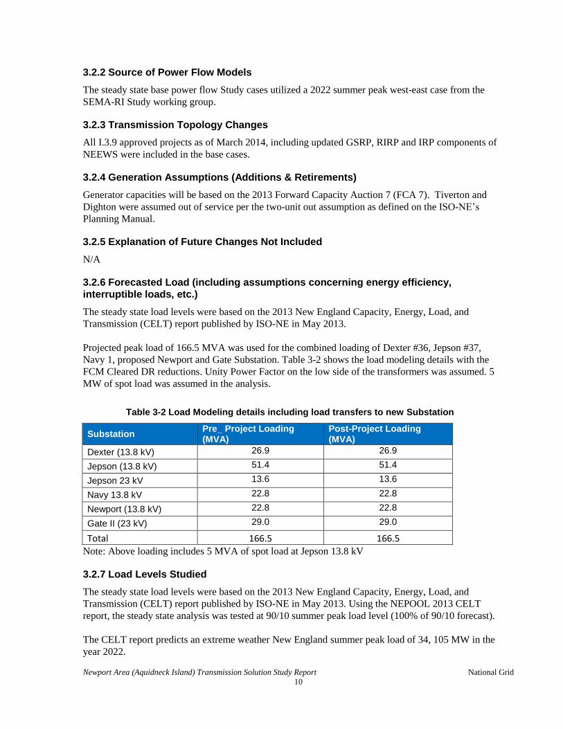
Projected peak load of 166.5 MVA was used for the combined loading of Dexter #36, Jepson #37,
Navy 1, proposed Newport and Gate Substation. Table 3-2 shows the load modeling details with the
FCM Cleared DR reductions. Unity Power Factor on the low side of the transformers was assumed. 5
MW of spot load was assumed in the analysis.
Table 3-2 Load Modeling details including load transfers to new Substation
Substation Pre_ Project Loading (MVA)
Post-Project Loading (MVA)
Dexter (13.8 kV) 26.9 26.9
Jepson (13.8 kV) 51.4 51.4
Jepson 23 kV 13.6 13.6
Navy 13.8 kV 22.8 22.8
Newport (13.8 kV) 22.8 22.8
Gate II (23 kV) 29.0 29.0
Total 166.5 166.5
Note: Above loading includes 5 MVA of spot load at Jepson 13.8 kV
3.2.7 Load Levels Studied
The steady state load levels were based on the 2013 New England Capacity, Energy, Load, and
Transmission (CELT) report published by ISO-NE in May 2013. Using the NEPOOL 2013 CELT
report, the steady state analysis was tested at 90/10 summer peak load level (100% of 90/10 forecast).
The CELT report predicts an extreme weather New England summer peak load of 34, 105 MW in the
year 2022.

Newport Area (Aquidneck Island) Transmission Solution Study Report National Grid
11
Case summaries for each of the load levels and conditions studied are included in Appendix C.
3.2.8 Load Power Factor Assumptions
Unity power factor represented on the transformer low side was assumed for the loads in the Study
area.
3.2.9 Transfer Levels
A summary of interface transfer levels for all relevant defined interfaces for the base case as well as
each alternative solution studied are shown at the end of Table 3-3 on the following section.
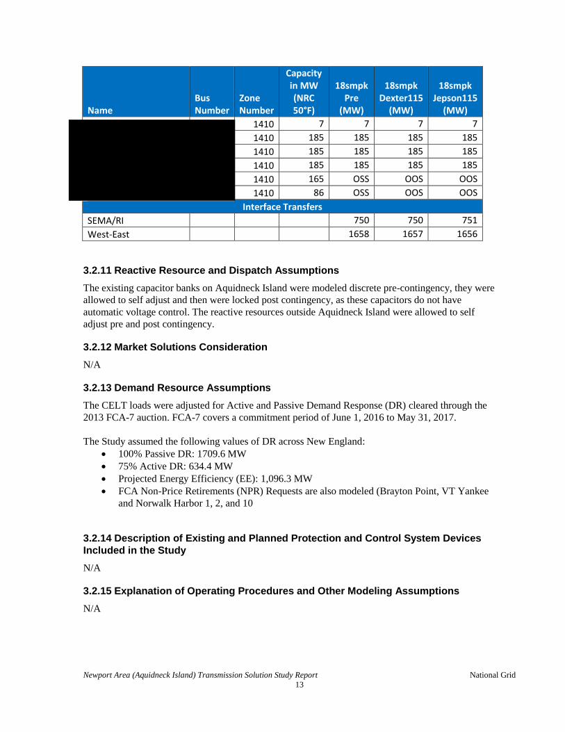
3.2.10 Generation Dispatch Scenarios
One dispatch scenario was created for summer peak load levels:
Tiv+Dig: Tiverton & Dighton OFF
Each of the two alternative solutions was evaluated using the above dispatch utilizing the Network
Resource Capability (NRC) Pmax generation profile.
The base case dispatch scenarios are shown in Table 3-3 below.
Table 3-3 Steady State Generation Dispatch Summary
Name Bus Number
Zone Number
Capacity in MW (NRC 50°F)
18smpk Pre
(MW)
18smpk Dexter115
(MW)
18smpk Jepson115
(MW)
Southeast Massachusetts Generation
1140 244 244 244 244
1140 244 244 244 244
1140 137 OSS OSS OSS
1140 108 OSS OSS OSS
1140 136 OSS OSS OSS
1140 107 OSS OSS OSS
1140 649 OSS OSS OSS
1140 441 OSS OSS OSS
1140 OOS OOS OOS OOS
1043 573 573 573 573
1043 563 563 563 563
1044 126 20 20 20
1044 108 17 17 17
1044 126 20 20 20
1044 108 17 17 17
1254 27 27 27 27
1254 22 22 22 22
1254 87 87 87 87

Newport Area (Aquidneck Island) Transmission Solution Study Report National Grid
12
Name Bus Number
Zone Number
Capacity in MW (NRC 50°F)
18smpk Pre
(MW)
18smpk Dexter115
(MW)
18smpk Jepson115
(MW)
1053 36 36 36 36
1053 28 28 28 28
1053 21 21 21 21
1160 163 OSS OOS OOS
1140 82 82 82 82
1140 69 69 69 69
1043 8 OSS OOS OSS
1063 58 58 58 58
1063 17 17 17 17
1033 52 52 52 52
1033 28 28 28 28
1063 53 53 53 53
1063 53 53 53 53
1044 6 6 6 6
ode Island Generation
1410 43 43 43 43
1410 43 43 43 43
1410 48 48 48 48
1410 108 108 108 108
1410 108 108 108 108
1410 104 104 104 104
1400 81 81 81 81
1400 81 81 81 81
1400 81 81 81 81
1400 81 81 81 81
1400 115 115 115 115
1400 114 114 114 114
1410 41 41 41 41
1410 24 24 24 24
1410 3 3 3 3
1410 3 3 3 3
1410 3 3 3 3
1410 3 3 3 3
1410 3 3 3 3
1410 3 3 3 3
Newport Area (Aquidneck Island) Transmission Solution Study Report National Grid
13
Name Bus Number
Zone Number
Capacity in MW (NRC 50°F)
18smpk Pre
(MW)
18smpk Dexter115
(MW)
18smpk Jepson115
(MW)
1410 7 7 7 7
1410 185 185 185 185
1410 185 185 185 185
1410 185 185 185 185
1410 165 OSS OOS OOS
1410 86 OSS OOS OOS
Interface Transfers
SEMA/RI 750 750 751
West-East 1658 1657 1656
3.2.11 Reactive Resource and Dispatch Assumptions
The existing capacitor banks on Aquidneck Island were modeled discrete pre-contingency, they were
allowed to self adjust and then were locked post contingency, as these capacitors do not have
automatic voltage control. The reactive resources outside Aquidneck Island were allowed to self
adjust pre and post contingency.
3.2.12 Market Solutions Consideration
N/A
3.2.13 Demand Resource Assumptions
The CELT loads were adjusted for Active and Passive Demand Response (DR) cleared through the
2013 FCA-7 auction. FCA-7 covers a commitment period of June 1, 2016 to May 31, 2017.
The Study assumed the following values of DR across New England:
100% Passive DR: 1709.6 MW
75% Active DR: 634.4 MW
Projected Energy Efficiency (EE): 1,096.3 MW
FCA Non-Price Retirements (NPR) Requests are also modeled (Brayton Point, VT Yankee
and Norwalk Harbor 1, 2, and 10
3.2.14 Description of Existing and Planned Protection and Control System Devices
Included in the Study
N/A
3.2.15 Explanation of Operating Procedures and Other Modeling Assumptions
N/A

Newport Area (Aquidneck Island) Transmission Solution Study Report National Grid
14
3.3 Stability Modeling Assumptions
3.3.1 Study Assumptions
The stability analysis will be performed on the recommended alternative solution during the ISO-NE
Proposed Plan Application (PPA) analysis.
3.3.2 Load Levels Studied
N/A
3.3.3 Load Models
N/A
3.3.4 Dynamic Models
N/A
3.3.5 Transfer Levels
N/A
3.3.6 Generation Dispatch Scenarios
N/A
3.3.7 Reactive Resource and Dispatch Assumptions
N/A
3.3.8 Explanation of Operating Procedures and Other Modeling Assumptions
N/A
3.4 Short Circuit Model Assumptions
3.4.1 Study Assumptions
The Study case used originated from the 2017 MASTER CASE developed in July 2013.
3.4.2 Short Circuit Model
ASPEN Breaker Rating Module software was used to perform short circuit analysis. Circuit breakers
at each Substation in the Study area were modeled with its connections to various elements,
interrupting capability, interrupting time and contact parting time. Reclosing information was
modeled for oil circuit breakers (when applicable) as these type of breakers need to be evaluated for
potential derating due to automatic reclosing.
The program model calculates faults currents and X/R ratios for three-phase, phase-phase, phase-
phase-ground and phase-ground faults at each Substation for all lines in and for line out situations.
The program follows the IEEE C37.010 method of E/X calculation to incorporate AC and DC
decrement effect multipliers to determine breaker fault duties.

Newport Area (Aquidneck Island) Transmission Solution Study Report National Grid
15
3.4.3 Contributing Generation Assumptions (Additions & Retirements)
Testing methodology included all generation facilities online utilizing the Flat Start option with
voltage starting at 1.03 per unit.
3.4.4 Generation and Transmission System Configurations
All proposed transmission and generation interconnection projects that have PPA approval and are
FCM certified were included in the Study case.
3.4.5 Boundaries
Short circuit analysis was conducted to identify available fault duty at National Grid buses within the
red boundary shown in Figure 3-1 below:

Newport Area (Aquidneck Island) Transmission Solution Study Report National Grid
16
3.4.6 Other Relevant Modeling Assumptions
N/A

Newport Area (Aquidneck Island) Transmission Solution Study Report National Grid
17
3.5 Other System Studies (such as transient network analysis, harmonic analysis, equipment assessments, etc.)
Sensitivity Analysis was performed using PSSE v33.3 in order to assess the voltage performance of
the proposed alternative solutions beyond the Study horizon.
The 2022 summer peak cases developed for each alternative solution was used to perform the voltage
performance analysis beyond the Study horizon. The Newport load was incremented in steps of 10
MW up to 50 MW; worst contingencies were analyzed at each incremental step.
The solution engine used was Fixed Slope decoupled Newton-Raphson and under pre-contingency
(all lines-in) conditions, all regulating devices were allowed to regulate or adjust in order to represent
conditions that would exist in the normal system in steady state. Similarly, under contingency
conditions, all regulating devices were allowed to regulate except for Load Tap Changers.
3.6 Changes in Study Assumptions
N/A

Newport Area (Aquidneck Island) Transmission Solution Study Report National Grid
18
Section 4 Analysis Methodology
4.1 Planning Standards and Criteria
Steady state thermal and voltage analyses examined system performance with the existing Dexter #36
and Jepson #37 configuration and the new Substation and the new 69 kV line between Jepson #37 and
the new Substation in Newport, RI in order to establish a baseline for comparison. System
performance was then re-evaluated with each alternative solution and compared with the previous
baseline performance to demonstrate the impact on the adjacent transmission area. The acceptance
criteria used for the Study are listed in sections Tables 4-1 and 4-2.
4.2 Performance Criteria
4.2.1 Steady State Criteria
The Study will be performed in accordance with:
Northeast Power Coordinating Council (NPCC) Directory 1 “Design and Operation of the
Bulk Power Systems”
ISO New England Planning Procedure No. 3, “Reliability Standards for the New England
Area Bulk Power System”
National Grid Transmission Group Procedure (TGP) #28 – “Transmission Planning Guide for
the National Grid USA Service Company”
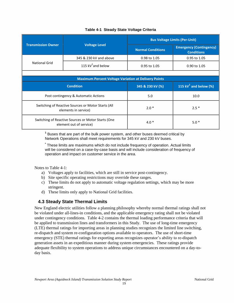
4.2.2 Steady State Thermal and Voltage Limits
Transmission voltage levels must be maintained within a prescribed bandwidth to ensure proper
operation of electrical equipment at both the transmission and customer voltage ranges. Equipment
damage and widespread power outages are more likely to occur when transmission-level voltages are
not maintained within pre-defined limits. Table 4-1 contains the voltage performance criteria that
will be used in this analysis.
Newport Area (Aquidneck Island) Transmission Solution Study Report National Grid
19
Table 4-1 Steady State Voltage Criteria
Transmission Owner Voltage Level
Bus Voltage Limits (Per-Unit)
Normal Conditions Emergency (Contingency)
Conditions
National Grid
345 & 230 kV and above 0.98 to 1.05 0.95 to 1.05
115 kV1and below
0.95 to 1.05 0.90 to 1.05
Maximum Percent Voltage Variation at Delivery Points
Condition 345 & 230 kV (%) 115 kV1 and below (%)
Post contingency & Automatic Actions 5.0 10.0
Switching of Reactive Sources or Motor Starts (All elements in service)
2.0 * 2.5 *
Switching of Reactive Sources or Motor Starts (One element out of service)
4.0 * 5.0 *
1 Buses that are part of the bulk power system, and other buses deemed critical by
Network Operations shall meet requirements for 345 kV and 230 kV buses.
* These limits are maximums which do not include frequency of operation. Actual limits will be considered on a case-by-case basis and will include consideration of frequency of operation and impact on customer service in the area.
Notes to Table 4-1:
a) Voltages apply to facilities, which are still in service post-contingency.
b) Site specific operating restrictions may override these ranges.
c) These limits do not apply to automatic voltage regulation settings, which may be more
stringent.
d) These limits only apply to National Grid facilities.
4.3 Steady State Thermal Limits
New England electric utilities follow a planning philosophy whereby normal thermal ratings shall not
be violated under all-lines-in conditions, and the applicable emergency rating shall not be violated
under contingency conditions. Table 4-2 contains the thermal loading performance criteria that will
be applied to transmission lines and transformers in this Study. The use of long-time emergency
(LTE) thermal ratings for importing areas in planning studies recognizes the limited line switching,
re-dispatch and system re-configuration options available to operators. The use of short-time
emergency (STE) thermal ratings for exporting areas recognizes operator’s ability to re-dispatch
generation assets in an expeditious manner during system emergencies. These ratings provide
adequate flexibility to system operations to address unique circumstances encountered on a day-to-
day basis.

Newport Area (Aquidneck Island) Transmission Solution Study Report National Grid
20
Table 4-2 Steady State Thermal Loading Criteria
System Condition Time Interval Maximum Allowable Facility Loading
Pre-Contingency
(all lines in) Continuous Normal Rating
Post-Contingency
Less than 15 minutes after
contingency occurs
Short Time Emergency
(STE) Rating
More than 15 minutes after
contingency occurs
Long Time Emergency
(LTE) Rating
4.3.1 Steady State Solution Parameters
Steady state analysis was performed with pre-contingency and post-contingency solution
parameters identified in Table 4-3. Under pre-contingency (base case) conditions, all
regulating devices were allowed to regulate or adjust in order to represent conditions that
would exist in the normal system in steady state. Similarly, under contingency conditions, all
regulating devices were allowed to regulate except for switched shunts within Aquidneck
Island and phase angle regulators, which are normally operated in the manual mode.
Aquidneck Island switched shunts were locked because these are not operated based on
voltage control.
Table 4-3 Steady State Solution Parameters
Case Area
Interchange
Transformer
LTCs
Phase Angle
Regulators
Switched
Shunts DC Taps
Pre-
Contingency Disabled Enabled Disabled Enabled Enabled
Post-
Contingency Disabled Locked Disabled
Enabled,
(Aquidneck
Island’s were
locked)
Enabled
4.3.2 Stability Performance Criteria
N/A
4.3.3 Short Circuit Performance Criteria
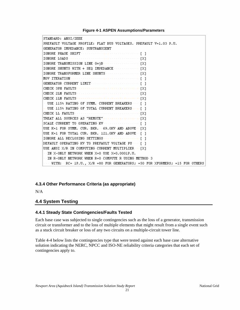
The ASPEN software was used to perform this analysis on the two alternative solutions. The ASPEN
Breaker Rating module was used to calculate the fault duties at breakers throughout the area in the
vicinity of the project. The program calculated fault currents and X/R ratios for three-phase-to-
ground, phase-phase-to-ground, single-phase-to-ground and phase-phase faults at each Substation bus
on Aquidneck Island. The ASPEN assumptions and parameters used in this analysis are displayed
below in Figure 4-1.
Newport Area (Aquidneck Island) Transmission Solution Study Report National Grid
21
Figure 4-1 ASPEN Assumptions/Parameters
4.3.4 Other Performance Criteria (as appropriate)
N/A
4.4 System Testing
4.4.1 Steady State Contingencies/Faults Tested
Each base case was subjected to single contingencies such as the loss of a generator, transmission
circuit or transformer and to the loss of multiple elements that might result from a single event such
as a stuck circuit breaker or loss of any two circuits on a multiple-circuit tower line.
Table 4-4 below lists the contingencies type that were tested against each base case alternative
solution indicating the NERC, NPCC and ISO-NE reliability criteria categories that each set of
contingencies apply to.

Newport Area (Aquidneck Island) Transmission Solution Study Report National Grid
22
Table 4-4 Steady State Contingencies Modeled
Contingency Type NERC Type
NPCC D-1 Section
ISO PP-3 Section
Generator (Single Unit) B1 5.4.1.a 3.1.a
Transmission Circuit B2 5.4.1.a 3.1.a
Transformer (low-side ≥ 69 kV) and all GSUs B3 5.4.1.a 3.1.a
Bus Section C1 5.4.1.a 3.1.a
Breaker Failure C2 5.4.1.e 3.1.e
Double Circuit Tower C5 5.4.1.b 3.1.b
The set of contingencies analyzed for the steady state analysis was based on the ISO-NE’s Model On-
Demand database, the contingency deck was filtered to obtain contingencies between Somerset and
High Hill Substations including the Newport, RI PSSE Zone 1420. Tables detailing each of the contingencies tested are included in Appendix F.
Only N-1 applicable contingencies were tested as there are no applicable N-1-1 contingencies within
Aquidneck Island.
4.4.2 Stability Contingencies/Faults Tested
N/A
4.4.3 Short Circuit Faults Tested
Short circuit analysis was performed on both alternative solutions with Greater Boston Projects,
NEEWS IRP, Brayton Point – to – Somerset 115 kV line and Somerset – to – Bell Rock 115 kV line.
The table below shows the buses tested.
Buses to Test in short Circuit Analysis
Bell Rock 115 kV
Dexter 115 kV
Dexter 69 kV
Gate II 69 kV
Existing Jepson 69 kV
New Jepson 115 kV
New Jepson 69 kV
Somerset 115 kV
Taunton 115 kV
Tiverton Power 115 kV

Newport Area (Aquidneck Island) Transmission Solution Study Report National Grid
23
Section 5 Development of Alternative Solutions
The proposed solution to resolve the identified capacity and asset conditions needs is to rebuild
Jepson on National Grid owned land across the street with a 115-69/23/13.8 kV Substation and
convert the 61 and 62 Lines from 69 kV to 115 kV. Two alternative solutions were studied to
determine if the existing Jepson Substation and the 61 and 62 lines could remain at 69 kV or if they
needed to be converted to 115 kV.
The steady state thermal and voltage analysis for each alternative solution was then performed to
evaluate the system performance with the existing configuration at Dexter and Jepson Substation in
order to establish a baseline for comparison. The system performance was then re-evaluated with the
two alternative solutions and compared with the previous baseline performance to demonstrate the
impact of each alternative solution on the local transmission area reliability.
5.1 Preliminary Screen of Alternative Solutions
Any configuration that did not resolve the projected thermal, voltage, asset condition issues and that
did not allow for future transmission expansion was dropped from further consideration.
5.2 Coordination of Alternative Solutions with Other Entities
Study coordination efforts were conducted with ISO-NE Planning management to discuss how to
progress this Study outside of the larger and currently ongoing SEMA/RI Study. ISO-NE Planning
management concurred with National Grid to allow us to bring a combined needs/solutions report
forward as long as we can demonstrate that the needs and recommended solutions are separate and
distinct from the larger SEMA/RI network. Through a conversation with ISO-NE Planning
management, instructions were provided to assure that the solutions identified in this report would not
affect the potential solutions for the SEMA/RI Study. This is one of the reasons why the RSP projects
791, 914 and 917 were modeled for this Study.
5.3 Description of Alternative Solutions
This report presents an advanced solution from the larger SEMA-RI scope, the transmission solutions
in this report addresses the local transmission supply to Aquidneck Island, which consists of the City
of Newport, Rhode Island, the Town of Middletown, RI and the Town of Portsmouth, RI. Figure 5-2
below shows a system diagram representation of the Study area.

Newport Area (Aquidneck Island) Transmission Solution Study Report National Grid
24
The following two alternative solutions were analyzed for this Study:
1. Reinforce the 69 kV (refer to Figure 5-3):
a. Rebuild and reconductor the 61 and 62 Lines at 69 kV (4.4 miles)
b. Relocate and rebuild Jepson Substation to address both asset condition and thermal
concerns
c. Reinforce Dexter Substation by reconfiguring the 115 kV and replacing the existing 115-
69 kV transformers with four 115-69 kV transformers.
2. Convert the 61 and 62 Lines and Jepson Substation to 115 kV (refer to Figure 5-4):
a. Rebuild and convert the 61 and 62 Lines to 115 kV (4.4 miles)
b. Relocate and rebuild Jepson Substation to address asset condition issues and thermal
concerns

Newport Area (Aquidneck Island) Transmission Solution Study Report National Grid
25

Newport Area (Aquidneck Island) Transmission Solution Study Report National Grid
26
Newport Area (Aquidneck Island) Transmission Solution Study Report National Grid
27
Section 6 Alternative Solution Performance Testing and Results
Both alternative solutions mitigate the asset condition issues; move Jepson Substation out of the 100
year flood plain and mitigate the thermal concerns within the Study horizon, however, Alternative
Solution 2 results with a more robust performance beyond the Study horizon. Alternative Solution 2
is able to accommodate a larger amount of future load growth without the need to undertake future
additional transmission upgrades between Dexter and Jepson Substations.
6.1 Steady State Performance Results
Each of the alternative solutions did not cause any N-0 thermal or voltage issues in the study year.
The N-1 Steady State results show the pre-existing overload on section of line 63 between Jepson and
Navy sub is not resolved for either alternative. Appendix G, Table 15-1 contains the N-1 Contingency
Results. The conductor clearance limitations on two spans of the 63 line will be mitigated by
relocating the conflicting distribution facilities.
6.1.1 N-0 Thermal and Voltage Performance Summary
Each of the alternative solutions did not cause any N-0 thermal or voltage issues.
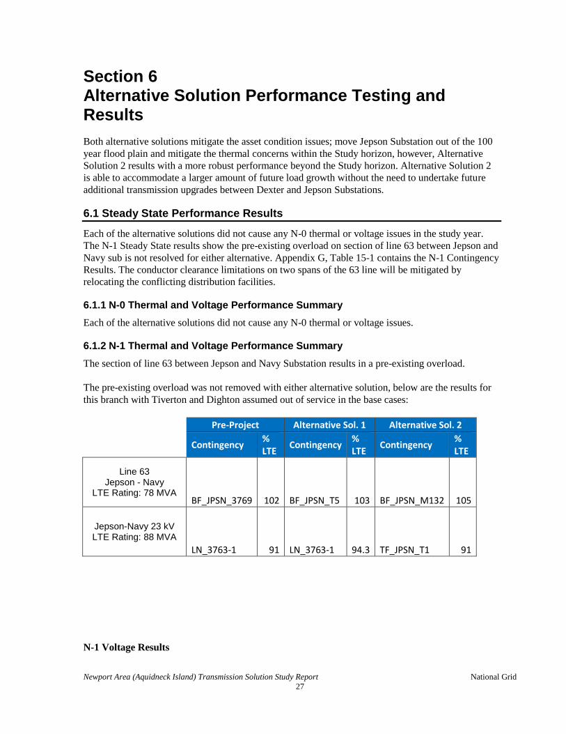
6.1.2 N-1 Thermal and Voltage Performance Summary
The section of line 63 between Jepson and Navy Substation results in a pre-existing overload.
The pre-existing overload was not removed with either alternative solution, below are the results for
this branch with Tiverton and Dighton assumed out of service in the base cases:
Pre-Project Alternative Sol. 1 Alternative Sol. 2
Contingency % LTE
Contingency % LTE
Contingency % LTE
Line 63 Jepson - Navy
LTE Rating: 78 MVA BF_JPSN_3769 102 BF_JPSN_T5 103 BF_JPSN_M132 105
Jepson-Navy 23 kV LTE Rating: 88 MVA
LN_3763-1 91 LN_3763-1 94.3 TF_JPSN_T1 91
N-1 Voltage Results

Newport Area (Aquidneck Island) Transmission Solution Study Report National Grid
28
Both Alternatives solutions performed adequately within the study horizon; however, Alternative
Solution 2 provides superior voltage performance beyond the study horizon. Alternative Solution 2 is
able to accommodate a larger amount of future load growth without the need to undertake future
additional transmission upgrades between Dexter and Jepson Substations.
To assess the robustness and voltage performance of each alternative solution, PV Analysis was
performed using PSSE v33.5. The analysis was performed by allowing the LTCs and capacitors
within Aquidneck Island to self adjust under all lines in conditions, contingency analysis was then
performed with locked LTCs. Load growth beyond the study horizon was concentrated in the city of
Newport, based on input from the distribution company.3
3 Analysis considered a future 69 kV line from Jepson to Newport Substations since the 23 kV line from Jepson to Gate II
would limit how much load would be backed up at Navy, Newport and Gate II Substations.

Newport Area (Aquidneck Island) Transmission Solution Study Report National Grid
29
0.7
0.75
0.8
0.85
0.9
0.95
1
1.05
0 5 10 15 20 25 30 35 40 45 50
Vo
ltag
e (
p.u
.)
Incremental MW Base Load = 166.5 MW
Alternative Solution 1 (69 kV Reinforcement) PV Curves for Jepson 69 kV Basecase
LN_L14LN_M13SBS_Dexter_1BS_Dexter_2TF_DEXTR_362LN_3761LN_3762LN_3764BF_JPN_62T3ABF_JPN_61BF_JPSN_6164ABF_JPSN_64ABF_JPSN_T3ABF_JPSN_62ABF_JPSN_T5ABF_DEXTR_M13BF_DEXTR_L14BF_DXTR_L142BF_DXTR_M132BF_DXTR_3661BF_DXTR_3662
Critical Contingency
0.7
0.75
0.8
0.85
0.9
0.95
1
1.05
0 5 10 15 20 25 30 35 40 45 50
Vo
ltag
e (
p.u
.)
Incremental MW Base Load = 166.5 MW
Alternative Solution 1 (69 kV Reinforcement) PV Curves for Newport 63 - 69 kV Basecase
LN_L14LN_M13SBS_Dexter_1BS_Dexter_2TF_DEXTR_362LN_3761LN_3762LN_3764BF_JPN_62T3ABF_JPN_61BF_JPSN_6164ABF_JPSN_64ABF_JPSN_T3ABF_JPSN_62ABF_JPSN_T5ABF_DEXTR_M13BF_DEXTR_L14BF_DXTR_L142BF_DXTR_M132BF_DXTR_3661BF_DXTR_3662
Critical Contingency
Alternative Solution 1 – Reinforce Dexter, rebuild the 61/62 lines and Jepson at 69 kV
The PV analysis for Alternative Solution 1 indicate National Grid’s low voltage criteria of 0.90 per
unit voltage will not be met after an incremental load of 16 MW at Newport Substation. The limiting
contingency is breaker failure L14-2 at Dexter Substation; the next limiting contingencies are
breakers failures M13 and M13-2 also Dexter Substation. These three contingencies take out one of

Newport Area (Aquidneck Island) Transmission Solution Study Report National Grid
30
0.7
0.75
0.8
0.85
0.9
0.95
1
1.05
0 5 10 15 20 25 30 35 40 45 50
Vo
ltag
e (
p.u
.)
Incremental MW Base Load = 166.5 MW
Alternative Solution 2 (Convert Jepson 115 kV) PV Curves for Jepson 115 kV
BasecaseLN_L14LN_M13SBS_JEPSON_1BS_Jepson_2ATF_JPSN_T1ABF_JPN_14T3ABF_JPSN_M13BF_JPSN_M132ABF_JPSN_T2ALN_3764BF_JPSN_T3ABF_JPSN_L14ATF_JPSN_T1T5ABF_JPSN_T5ABF_JPSN_T1ALOW LIMIT
Critical Contingency
0.7
0.75
0.8
0.85
0.9
0.95
1
1.05
0 5 10 15 20 25 30 35 40 45 50
Vo
ltag
e (
p.u
.)
Incremental MW Base Load = 166.5 MW
Alternative Solution 2 (Convert Jepson 115 kV) PV Curves for Newport 63 - 69 kV
BasecaseLN_L14LN_M13SBS_JEPSON_1BS_Jepson_2ATF_JPSN_T1ABF_JPN_14T3ABF_JPSN_M13BF_JPSN_M132ABF_JPSN_T2ALN_3764BF_JPSN_T3ABF_JPSN_L14ATF_JPSN_T1T5ABF_JPSN_T5ABF_JPSN_T1ALOW LIMIT
Critical Contingency
the two 115 kV line supplying Dexter along with the 115-69 kV transformers supplying the 61 or 62
lines.
Alternative Solution 2 – Convert 61/62 lines and Jepson Substation to 115 kV
Newport Area (Aquidneck Island) Transmission Solution Study Report National Grid
31
0.7
0.75
0.8
0.85
0.9
0.95
1
1.05
0 5 10 15 20 25 30 35 40 45 50
Vo
ltag
e (
p.u
.)
Incremental MW Base Load = 166.5 MW
Alternative Solution 2 (Convert Jepson 115 kV) PV Curves for Newport 63 with 8 Mvar 69 kV Cap.
BasecaseLN_L14LN_M13SBS_JEPSON_1BS_Jepson_2ATF_JPSN_T1ABF_JPN_14T3ABF_JPSN_M13BF_JPSN_M132ABF_JPSN_T2ALN_3764BF_JPSN_T3ABF_JPSN_L14ATF_JPSN_T1T5A
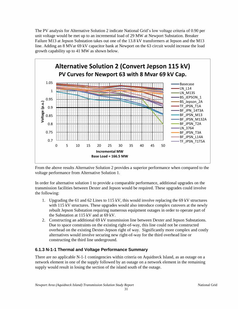
The PV analysis for Alternative Solution 2 indicate National Grid’s low voltage criteria of 0.90 per
unit voltage would be met up to an incremental load of 29 MW at Newport Substation. Breaker
Failure M13 at Jepson Substation takes out one of the 13.8 kV transformers at Jepson and the M13
line. Adding an 8 MVar 69 kV capacitor bank at Newport on the 63 circuit would increase the load
growth capability up to 41 MW as shown below.
From the above results Alternative Solution 2 provides a superior performance when compared to the
voltage performance from Alternative Solution 1.
In order for alternative solution 1 to provide a comparable performance, additional upgrades on the
transmission facilities between Dexter and Jepson would be required. These upgrades could involve
the following:
1. Upgrading the 61 and 62 Lines to 115 kV, this would involve replacing the 69 kV structures
with 115 kV structures. These upgrades would also introduce complex cutovers at the newly
rebuilt Jepson Substation requiring numerous equipment outages in order to operate part of
the Substation at 115 kV and at 69 kV.
2. Constructing an additional 69 kV transmission line between Dexter and Jepson Substations.
Due to space constraints on the existing right-of-way, this line could not be constructed
overhead on the existing Dexter-Jepson right of way. Significantly more complex and costly
alternatives would involve securing new right-of-way for the third overhead line or
constructing the third line underground.
6.1.3 N-1-1 Thermal and Voltage Performance Summary
There are no applicable N-1-1 contingencies within criteria on Aquidneck Island, as an outage on a
network element in one of the supply followed by an outage on a network element in the remaining
supply would result in losing the section of the island south of the outage.

Newport Area (Aquidneck Island) Transmission Solution Study Report National Grid
32
6.1.4 Results of Extreme Contingency Testing
N/A
6.1.5 Results of Delta P Testing
N/A
6.2 Stability Performance Results
6.2.1 Stability Performance Results
N/A
6.2.2 All-Lines-In Stability Performance Results
N/A
6.2.3 Line-Out-of-Service Stability Performance Results
N/A
6.3 Short Circuit Performance Results
The alternative solutions did not significantly increase the short circuit duty outside Aquidneck
Island. The maximum observed short circuit increase outside Aquidneck Island is 1% at the Tiverton
Power 115 kV bus. Within Aquidneck Island the only significant short circuit duty increase was
observed at the Gate II 69 kV bus. Alternative Solution 1 (69 kV Reinforcement) resulted in a short
circuit duty percent increase from 21% to 51% of existing equipment interrupting capability,
Alternative Solution 2 (Jepson 115 kV Conversion) resulted in a short circuit duty percent increase
from 21% to 47%.
Section 6.3.1 below shows the short circuit results pre and post project with Greater Boston Project,
NEEWS IRP, GRI Projects (RSP 791, 914 and 917). In order to account for a potential impact of a
future 69 kV line between Jepson and Newport Substation, a second 115-69 kV transformer at Jepson
along with a new 69 kV line between Jepson and Newport Substation was modeled in the cases.
The Alternatives did not result in any breaker becoming over-dutied.

Newport Area (Aquidneck Island) Transmission Solution Study Report National Grid
33
6.3.1 Short Circuit Performance Results
Without GRI Projects With GRI Projects
Substation Breaker Alternative Duty (%)
Duty (A)
Breaker Capability
Isc X/R Duty (%)
Duty (A)
Breaker Capability
Isc X/R
Somerset 115 kV
1128
Pre 55.3 24987 45185 24328 8.7 78.5 35487 45185 32921 12.5
Dexter 115 55.3 24991 45185 24331 8.7 78.5 35488 45185 32921 12.5
Jepson 115 55.5 25090 45185 24428 8.7 78.8 35608 45185 33033 12.5
1138
Pre 55.3 24987 45185 24328 8.7 78.5 35487 45185 32921 12.5
Dexter 115 55.3 24991 45185 24331 8.7 78.5 35488 45185 32921 12.5
Jepson 115 55.5 25090 45185 24428 8.7 78.8 35608 45185 33033 12.5
TL713
Pre 62 23696 38222 23696 8.8 84.7 32386 38222 32386 12.6
Dexter 115 62 23699 38222 23699 8.8 84.7 32387 38222 32387 12.6
Jepson 115 62.3 23796 38222 23796 8.8 85.0 32499 38222 32499 12.6
TL812
Pre 47.3 22321 47222 22321 8.4 69.2 32670 47222 32670 12.5
Dexter 115 47.3 22324 47222 22324 8.4 69.2 32671 47222 32671 12.5
Jepson 115 47.5 22421 47222 22421 8.4 69.4 32778 47222 32778 12.5
Bell Rock 115 kV
1802
Pre 25.6 16120 63000 16120 8.2 39.4 24817 63000 24817 10.7
Dexter 115 25.6 16125 63000 16125 8.2 39.4 24825 63000 24825 10.7
Jepson 115 25.6 16146 63000 16146 8.2 39.5 24860 63000 24860 10.7
1805
Pre 25.6 16120 63000 16120 8.2 39.4 24817 63000 24817 10.7
Dexter 115 25.6 16125 63000 16125 8.2 39.4 24825 63000 24825 10.7
Jepson 115 25.6 16146 63000 16146 8.2 39.5 24860 63000 24860 10.7
Tiverton Power 115 kV

Newport Area (Aquidneck Island) Transmission Solution Study Report National Grid
34
Without GRI Projects With GRI Projects
Substation Breaker Alternative Duty (%)
Duty (A)
Breaker Capability
Isc X/R Duty (%)
Duty (A)
Breaker Capability
Isc X/R
Dexter 115 kV
L14
Pre N/A N/A N/A N/A N/A N/A N/A N/A N/A N/A
Dexter 115 20.9 8369 40000 8369 8.9 22.2 8897 40000 8897 8.5
Jepson 115 N/A N/A N/A N/A N/A N/A N/A N/A N/A N/A
L14-2
Pre N/A N/A N/A N/A N/A N/A N/A N/A N/A N/A
Dexter 115 21 8410 40000 8410 8.9 22.3 8938 40000 8938 8.5
Jepson 115 N/A N/A N/A N/A N/A N/A N/A N/A N/A N/A
M13
Pre N/A N/A N/A N/A N/A N/A N/A N/A N/A N/A
Dexter 115 21 8410 40000 8410 8.9 22.3 8938 40000 8938 8.5
Jepson 115 N/A N/A N/A N/A N/A N/A N/A N/A N/A N/A
M13-2
Pre N/A N/A N/A N/A N/A N/A N/A N/A N/A N/A
Dexter 115 20.9 8369 40000 8369 8.9 22.2 8897 40000 8897 8.5
Jepson 115 N/A N/A N/A N/A N/A N/A N/A N/A N/A N/A
Dexter 69 kV
361T
Pre 30.5 5795 19002 5731 9.8 31.0 5884 19002 5822 9.7
Dexter 115 30 9438 31500 9438 9.6 30.8 9717 31500 9717 9.4
Jepson 115 N/A N/A N/A N/A N/A N/A N/A N/A N/A N/A
362T
Pre 84.6 6740 7969 6707 9.5 86.3 6875 7969 6843 9.4
Dexter 115 27.9 8789 31500 8789 11.1 28.8 9078 31500 9078 10.9
Jepson 115 N/A N/A N/A N/A N/A N/A N/A N/A N/A N/A
363T
Pre 84.6 6740 7969 6707 9.5 86.3 6875 7969 6843 9.4
Dexter 115 N/A N/A N/A N/A N/A N/A N/A N/A N/A N/A
Jepson 115 N/A N/A N/A N/A N/A N/A N/A N/A N/A N/A
Existing Jepson
3763
Pre N/A N/A N/A N/A N/A N/A N/A N/A N/A N/A
Dexter 115 N/A N/A N/A N/A N/A N/A N/A N/A N/A N/A
Jepson 115 22.5 7090 31500 7090 10.7 23.2 7295 31500 7295 10.5
3764 Pre 25 4893 19556 4893 7.8 25.5 4994 19556 4994 8.5

Newport Area (Aquidneck Island) Transmission Solution Study Report National Grid
35
Without GRI Projects With GRI Projects
Substation Breaker Alternative Duty (%)
Duty (A)
Breaker Capability
Isc X/R Duty (%)
Duty (A)
Breaker Capability
Isc X/R
Dexter 115 N/A N/A N/A N/A N/A N/A N/A N/A N/A N/A
Jepson 115 N/A N/A N/A N/A N/A N/A N/A N/A N/A N/A
3765
Pre 28 4954 17722 4923 8.7 28.6 5069 17722 5040 8.5
Dexter 115 N/A N/A N/A N/A N/A N/A N/A N/A N/A N/A
Jepson 115 N/A N/A N/A N/A N/A N/A N/A N/A N/A N/A
3766
Pre 39.1 7638 19556 7638 8.9 39.9 7805 19556 7805 8.7
Dexter 115 N/A N/A N/A N/A N/A N/A N/A N/A N/A N/A
Jepson 115 N/A N/A N/A N/A N/A N/A N/A N/A N/A N/A
3767
Pre 98.1 7691 7841 7638 8.9 100.2 7856 7841 7805 8.7
Dexter 115 N/A N/A N/A N/A N/A N/A N/A N/A N/A N/A
Jepson 115 N/A N/A N/A N/A N/A N/A N/A N/A N/A N/A
3769
Pre 59.8 4921 8233 4890 8.7 61.0 5023 8233 4994 8.5
Dexter 115 N/A N/A N/A N/A N/A N/A N/A N/A N/A N/A
Jepson 115 N/A N/A N/A N/A N/A N/A N/A N/A N/A N/A
New Jepson
69 kV: 61 115 kV: M13
Pre N/A N/A N/A N/A N/A N/A N/A N/A N/A N/A
Dexter 115 27.4 8617 31500 8617 9.2 28.0 8833 31500 8833 9.0
Jepson 115 23.2 9277 40000 9277 9.1 24.2 9676 40000 9676 8.8
69 kV: 61-64 115 kV: M13-
T2
Pre N/A N/A N/A N/A N/A N/A N/A N/A N/A N/A
Dexter 115 26.5 8349 31500 8349 9.3 27.2 8553 31500 8553 9.2
Jepson 115 21.7 8680 40000 8680 9.5 22.6 9032 40000 9032 9.2
69 kV: 62 115 kV: L14
Pre N/A N/A N/A N/A N/A N/A N/A N/A N/A N/A
Dexter 115 27.4 8617 31500 8617 9.2 28.0 8833 31500 8833 9.0
Jepson 115 23.2 9277 40000 9277 9.1 24.2 9676 40000 9676 8.8
69 kV: 62-T3 115 kV: L14-T3
Pre N/A N/A N/A N/A N/A N/A N/A N/A N/A N/A
Dexter 115 25.8 8131 31500 8131 9.0 26.4 8325 31500 8325 8.9
Newport Area (Aquidneck Island) Transmission Solution Study Report National Grid
36
Without GRI Projects With GRI Projects
Substation Breaker Alternative Duty (%)
Duty (A)
Breaker Capability
Isc X/R Duty (%)
Duty (A)
Breaker Capability
Isc X/R
Jepson 115 22.8 9126 40000 9126 9.2 23.8 9516 40000 9516 8.9
69 kV: 63 115 kV: T1
Pre N/A N/A N/A N/A N/A N/A N/A N/A N/A N/A
Dexter 115 27.4 8617 31500 8617 9.2 28.0 8833 31500 8833 9.0
Jepson 115 23.2 9277 40000 9277 9.1 24.2 9676 40000 9676 8.8
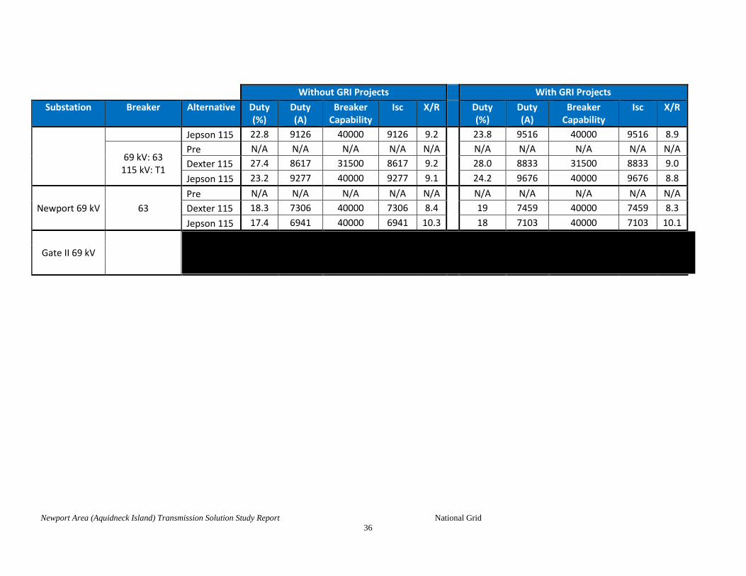
Newport 69 kV 63
Pre N/A N/A N/A N/A N/A N/A N/A N/A N/A N/A
Dexter 115 18.3 7306 40000 7306 8.4 19 7459 40000 7459 8.3
Jepson 115 17.4 6941 40000 6941 10.3 18 7103 40000 7103 10.1
Gate II 69 kV

Newport Area (Aquidneck Island) Transmission Solution Study Report National Grid
37
6.4 Other Assessment Performance Results
N/A
6.5 Sensitivity Case Testing Results
N/A

Newport Area (Aquidneck Island) Transmission Solution Study Report National Grid
38
Section 7 Comparison of Alternative Solutions
The solutions alternatives were compared on the thermal and voltage impacts within Aquidneck
Island. Both alternative solutions mitigate the asset condition issues and thermal concerns within the
study area. Solution Alternative 1 however, does not compare favorably with Alternative Solution 2,
which costs $1.0 million more and does not provide a superior performance as it is not able to
accommodate a larger amount of future load growth without additional investments between Dexter
and Jepson Substations.
7.1 Factors Used to Compare Alternative Solutions
The key factors used for comparison and differentiations of alternative solutions were the following:
1. The cost for the transmission upgrades to resolve the observed thermal issues while
mitigating the asset condition issues at Jepson Substation and resolve the observed thermal
issues
2. Robustness; performance beyond the Study horizon allowing for future load growth
3. Project duration
7.2 Cost Estimates for Selected Alternative Solutions
The conceptual grade estimate was developed to compare the two alternative solutions, which would
mitigate the thermal overloads and the asset condition issues at Jepson Substation.

Newport Area (Aquidneck Island) Transmission Solution Study Report National Grid
39
7.3 Comparison of Alternative Solutions
Aquidneck Island Transmission Solutions
Alternative Solution 1 Alternative Solution 2
Transmission Upgrades
1. Reconstruct the 61 and 62 Lines at 69 kV 2. Relocate and Rebuild Jepson Substation to address
both asset condition and thermal concerns 3. Reinforce Dexter Substation by reconfiguring the
115 kV into a breaker and half layout initially operated with 4 breakers, replacing the existing 115-69 kV transformers with four 115-69 kV transformers.
1. Reconstruct the 61 and 62 Lines at 115 kV 2. Relocate and Rebuild Jepson Substation to
address both asset condition and thermal concerns
3. Reconfigure Dexter by Removing the 115-69 kV transformers and 69 kV equipment. Reconfigure the 115 kV yard by removing the 115 kV circuit switchers and installing load break switches on the line sides of the 115/13.8 kV transformer. Install a 115 kV circuit switcher to protect the 115/13.8 kV transformer.
Transmission Line Cost (in 2014 $USD millions with -25/+50% accuracy level)
$11.5 (PTF: $0) $22.1 (PTF: All)
Transmission Substation Cost (in 2014 $USD with -25/+50% accuracy level)
Dexter ($millions)
$18.3 (PTF: $9) $3.9 (PTF: $3.0)
Jepson ($millions)
$10.3 (PTF: $0) $13.2 (PTF: $9.5)
Total $40.1 (PTF: $9) $39.2 (PTF: $34.6)
Project Construction Time 30 months 24 months

Newport Area (Aquidneck Island) Transmission Solution Study Report National Grid
40
7.4 Comparison Matrix of Alternative Solutions
Table 7-1 below provides a comparison matrix showing the performance of the alternative solutions.
Table 7-1 Comparison Matrix of Alternative Solutions
Factors Considered for Comparison of Alternative Solutions
Alt
ern
ativ
e So
luti
on
1
Alt
ern
ativ
e So
luti
on
2
1. Overall Cost a. Lower overall cost Estimated installed cost in 2014 dollars (millions)
$40.10
$39.20
2. Expansion Capabilities
a. a. Allows for future load growth and expansion to existing area Substations
b. Robustness (superior performance)
3. Early In Service Date
a. Shorter construction time
b. Less transmission work scope
c. Less outages required
- Does not satisfy this objective
- Achieves this objective

Newport Area (Aquidneck Island) Transmission Solution Study Report National Grid
41
Section 8 Conclusion
The two solutions alternatives resolve the asset condition issues at Jepson and resolve the thermal
issues at Dexter and Jepson Substations and on the 61 and 62 Lines. However, alternative solution 1
costs $1.0 million more and from a performance perspective, it does not compare favorably to
alternative solution 2. Alternative Solution 1 would only allow a 9.6% load growth due to two breaker
failures at Dexter 115 kV. Alternative Solution 2 would allow 17.4% of load growth. Furthermore
installing an 8 MVar 69 kV capacitor bank on Newport 63 would increase the load growth capability
up to 24%.
In order to increase the load serving capability of alternative solution 1, more transmission upgrades
between Dexter and Jepson Substations would be required. These upgrades could take the form of
reconstructing the 61 and 62 lines from 69 kV to 115 kV or installing a third transmission line from
Dexter to Jepson, which cannot be constructed overhead on the existing right of way due to the space
constraints along the entire length of right of way.
8.1 Recommended Solution Description
The recommended solution based on the lower cost and superior performance along with less
construction duration and with less outage complexity is alternative solution 2. This alternative
solution converts the 61 and 62 Lines and Jepson Substation from 69 kV to 115 kV. The scope of this
solution is the following:
o 61/62 Lines: Reconstruct the 61 and 62 Lines between Dexter and Jepson at 115 kV
o Jepson Substation: Relocate and Rebuild Jepson Substation at 115 kV
o Dexter Substation: Reconfigure Dexter by removing the 115-69 kV transformers and
69 kV equipment. Reconfigure the 115 kV Yard by removing the 115 kV circuit
switchers and installing load break switches north and south of the 115/13.8 kV
transformer. Install a 115 kV circuit switcher to protect the 115/13.8 kV transformer
8.2 Solution Component Year of Need
Based on the Critical Load Level Analysis the year of need for the overall project is between now and
June 2016. The need to resolve the thermal issues on the 69 kV ring at Jepson, 61 and 62 Lines is in
the past. The need to resolve the thermal issues on the 115-69 kV transformers at Dexter is June 2016.
8.3 Schedule for Implementation, Lead Times and Documentation of Continuing Need
The existing Jepson Substation is not a BPS facility, it is anticipated that the new Jepson
configuration along with the required transmission upgrades will not result in any additional facilities
becoming NPCC, A-10 defined BPS facilities, and this will be confirmed as part of the PPA analysis
on the recommended alternative. The Study performed complies with the NERC TPL standards. The
planned completion date of the preferred solution as described in Section 8.1 above is 06/2019. This
Study has reviewed the continuing need and has identified a recommended solution.

Newport Area (Aquidneck Island) Transmission Solution Study Report National Grid
ISO New England Inc.
42
Section 9 Appendix A: Load Forecast
Table 9-1
2013 Seasonal Peak Load Forecast Distributions

Newport Area (Aquidneck Island) Transmission Solution Study Report National Grid
43
Section 10 Appendix B: Upgrades Included in Base Case
All I.3.9 approved transmission projects as of March 2014 are included in the base case,
including updated GSRP, RIRP, and IRP components of NEEWS
Solutions for surrounding areas that do not yet have PPA approval have been included –
Greater Boston Working Group (GBWG) solutions presented at the March 2012 PAC
meeting
Non-NEEWS portions of GRI are included: New Brayton Point – Somerset 115 kV line, new
Somerset Bell Rock 115 kV line and Bell Rock upgrades. These projects were included as a
proxy to mitigate the larger network needs in the Somerset/Bell Rock area and do not
mitigate the thermal needs on Aquidneck Island.

Newport Area (Aquidneck Island) Transmission Solution Study Report National Grid
44
Section 11 Appendix C: Case Summaries and Load Flow Plots

Newport Area (Aquidneck Island) Transmission Solution Study Report National Grid
45
Section 12 Appendix D: Assessment Criteria (i.e., Steady State Thermal and Voltage Criteria)
Steady State Thermal Limits
New England electric utilities follow a planning philosophy whereby normal thermal ratings shall not be violated
under all-lines-in conditions, and the applicable emergency rating shall not be violated under contingency
conditions. Table 4-2 contains the thermal loading performance criteria that will be applied to transmission lines
and transformers in this Study. The use of long-time emergency (LTE) thermal ratings for importing areas in
planning studies recognizes the limited line switching, re-dispatch and system re-configuration options available
to operators. The use of short-time emergency (STE) thermal ratings for exporting areas recognizes operator’s
ability to re-dispatch generation assets in an expeditious manner during system emergencies. These ratings
provide adequate flexibility to system operations to address unique circumstances encountered on a day-to-day
basis.
System Condition Time Interval Maximum Allowable Facility Loading
Pre-Contingency
(all lines in) Continuous Normal Rating
Post-Contingency
Less than 15 minutes after
contingency occurs
Short Time Emergency
(STE) Rating
More than 15 minutes after
contingency occurs
Long Time Emergency
(LTE) Rating
Table 13-1 Steady State Thermal Loading Criteria

Newport Area (Aquidneck Island) Transmission Solution Study Report National Grid
46
Steady State Voltage Limits
Transmission voltage levels must be maintained within a prescribed bandwidth to ensure proper operation of
electrical equipment at both the transmission and customer voltage ranges. Equipment damage and widespread
power outages are more likely to occur when transmission-level voltages are not maintained within pre-defined
limits. Table 4-1 contains the voltage performance criteria that will be used in this analysis.
Transmission Owner Voltage Level
Bus Voltage Limits (Per-Unit)
Normal Conditions Emergency (Contingency)
Conditions
National Grid
345 & 230 kV and
above 0.98 to 1.05 0.95 to 1.05
115 kV
1
and below
0.95 to 1.05 0.90 to 1.05
Maximum Percent Voltage Variation at Delivery Points
Condition 345 & 230 kV (%) 115 kV1 and below (%)
Post contingency & Automatic Actions
5.0 10.0
Switching of Reactive Sources or Motor Starts (All elements in
service) 2.0 * 2.5 *
Switching of Reactive Sources or Motor Starts (One element out of
service) 4.0 * 5.0 *
1 Buses that are part of the bulk power system, and other buses deemed critical by Network
Operations shall meet requirements for 345 kV and 230 kV buses.
* These limits are maximums which do not include frequency of operation. Actual limits will be considered on a case-by-case basis and will include consideration of frequency of operation and impact on customer service in the area.
Table 12-1 Steady State Voltage Criteria
Notes to Table 4-1:
e) Voltages apply to facilities which are still in service post-contingency.
f) Site specific operating restrictions may override these ranges.
g) These limits do not apply to automatic voltage regulation settings which may be more stringent.
h) These limits only apply to National Grid facilities.

Newport Area (Aquidneck Island) Transmission Solution Study Report National Grid
47
Section 13 Appendix E: Contingency List
Table 13-1 Steady State Contingency List
Contingency Label NERC Type Description
LN_SOM_BELRK B2 FUTURE CTG (RSP - 0914) - Greater RI - New 115 kV Line (Somerset - Bell Rock)
LN_109 B2 FUTURE CTG (RSP - 0917) - Greater RI - Bell Rock Substation Expansion
LN_D21 B2 FUTURE CTG (RSP - 0917) - Greater RI - Bell Rock Substation Expansion
LN_L14GRI B2 FUTURE CTG (RSP - 0917) - Greater RI - Bell Rock Substation Expansion
LN_M13_N GRI B2 FUTURE CTG (RSP - 0917) - Greater RI - Bell Rock Substation Expansion
LN_M13_S GRI B2 FUTURE CTG (RSP - 0917) - Greater RI - Bell Rock Substation Expansion
LN_N12 B2 FUTURE CTG (RSP - 0917) - Greater RI - Bell Rock Substation Expansion
GN_BRA1 B1 BRA1 - Brayton Point Unit 1
GN_BRA2 B1 BRA2 - Brayton Point Unit 2
GN_BRAD B1 BRAD - Brayton Point Diesel
GN_BRA3 B1 BRA3 - Brayton Point Unit 3
GN_BRA4 B1 BRA4 - Brayton Point Unit 4
GN_CLE8 B1 CLE8 - Cleary G8
GN_CLERY9_CC B1 Cleary G9 Combined Cycle
GN_DAR3 B1 DAR3 - Dartmouth Power C3
GN_DART_CC B1 DART - Dartmouth Power Combined Cycle
GN_MANC09_CC B1 Manchester 09 Combined Cycle
GN_MANC10_CC B1 Manchester 10 Combined Cycle
GN_MANC11_CC B1 Manchester 11 Combined Cycle
GN_PAWP_CC B1 Pawtucket Power Combined Cycle
GN_SEM1 B1 SEM1 - SEMASS G1
GN_SEM2 B1 SEM2 - SEMASS G2
GN_DIGH B1 DIGH - Dighton Power
GN_TVRTN_CC B1 EMI Tiverton Combined Cycle
BS_SOMRSET_W C1 Somerset 115kV West Bus
BF_BELLRK_H C2 FUTURE CTG (RSP - 0914) - Greater RI - New 115 kV Line (Somerset - Bell Rock) Bell Rock 115 kV position H Breaker Failure
BF_BELLRK_I C2 FUTURE CTG (RSP - 0914) - Greater RI - New 115 kV Line (Somerset - Bell Rock) Bell Rock 115 kV position I Breaker Failure
BF_SOMST_34 C2 FUTURE CTG (RSP - 0914) - Greater RI - New 115 kV Line (Somerset - Bell Rock) Somerset TL34 Breaker Failure
BF_SOMST_B C2 FUTURE CTG (RSP - 0914) - Greater RI - New 115 kV Line (Somerset - Bell Rock) Somerset 115kV B Breaker Failure (Num Not Finalized)
BF_BELLRK_A C2 FUTURE CTG (RSP - 0917) - Greater RI - Bell Rock Substation Expansion Bell Rock 115 kV position A Breaker Failure
BF_BELLRK_B C2 FUTURE CTG (RSP - 0917) - Greater RI - Bell Rock Substation Expansion Bell Rock 115 kV position B Breaker Failure

Newport Area (Aquidneck Island) Transmission Solution Study Report National Grid
48
Contingency Label NERC Type Description
BF_BELLRK_C C2 FUTURE CTG (RSP - 0917) - Greater RI - Bell Rock Substation Expansion Bell Rock 115 kV position C Breaker Failure
BF_BELLRK_D C2 FUTURE CTG (RSP - 0917) - Greater RI - Bell Rock Substation Expansion Bell Rock 115 kV position D Breaker Failure
BF_BELLRK_E C2 FUTURE CTG (RSP - 0917) - Greater RI - Bell Rock Substation Expansion Bell Rock 115 kV position E Breaker Failure
BF_BELLRK_F C2 FUTURE CTG (RSP - 0917) - Greater RI - Bell Rock Substation Expansion Bell Rock 115 kV position F Breaker Failure
BF_BELLRK_G C2 FUTURE CTG (RSP - 0917) - Greater RI - Bell Rock Substation Expansion Bell Rock 115 kV position G Breaker Failure
BF_HIGH_HL_1 C2 FUTURE CTG (RSP - 0917) - Greater RI - Bell Rock Substation Expansion High Hill 11142 Breaker Failure
BF_HIGH_HL_D C2 FUTURE CTG (RSP - 0917) - Greater RI - Bell Rock Substation Expansion High Hill D2142 Breaker Failure
BF_SOMST_12 C2 Somerset TL12 Breaker Failure
BF_SOMST_128 C2 FUTURE CTG (RSP - 0917) - Greater RI - Bell Rock Substation Expansion Somerset 1128 Breaker Failure
BF_SOMST_138 C2 FUTURE CTG (RSP - 0917) - Greater RI - Bell Rock Substation Expansion Somerset 1138 Breaker Failure
BF_SOMST_23 C2 Somerset TL23 Breaker Failure
BF_SOMST_34 C2 Somerset TL34 Breaker Failure
BF_SOMST_45 C2 Somerset TL45 Breaker Failure
BF_SOMST_713 C2 FUTURE CTG (RSP - 0917) - Greater RI - Bell Rock Substation Expansion Somerset TL713 Breaker Failure
BF_SOMST_812 C2 FUTURE CTG (RSP - 0917) - Greater RI - Bell Rock Substation Expansion Somerset TL812 Breaker Failure
BF_TIVRTON_2 C2 FUTURE CTG (RSP - 0917) - Greater RI - Bell Rock Substation Expansion Tiverton 52-2 Breaker Failure
BF_TIVRTON_3 C2 Tiverton 52-3 Breaker Failure
BF_TIVRTON_4 C2 Tiverton 52-4 Breaker Failure
DC_L14_M13S C5 FUTURE CTG (RSP - 0917) - Greater RI - Bell Rock Substation Expansion Lines L14 (115kV) and M13S (115kV) DCT
DC_M13N_N12 C5 FUTURE CTG (RSP - 0917) - Greater RI - Bell Rock Substation Expansion Lines M13N (115kV) and N12 (115kV) DCT
TF_DEXTR_361 B3 XFMR 361 AT DEXTER 115-69 kV
TF_DEXTR_362 B3 XFMR 361 AT DEXTER 115-69 kV
LN_3761 B2 National Grid's 61 69 kV Line
LN_3762 B2 National Grid's 62 69 kV Line
LN_3763 B2 National Grid's 63 69 kV Line
LN_3763-1 B2 National Grid's 63-1 Line section
BF_JPSN_3764 C2 BREAKER 3764 AT JEPSON 69 kV
BF_JPN_3764a C2 BREAKER 3764 AT JEPSON 69 kV, close 23kV tie
BF_JPSN_3765 C2 BREAKER 3765 AT JEPSON 69 kV
BF_JPN_3765a C2 BREAKER 3765 AT JEPSON 69 kV, close 23kV tie

Newport Area (Aquidneck Island) Transmission Solution Study Report National Grid
49
Contingency Label NERC Type Description
BF_JPSN_3766 C2 BREAKER 3766 AT JEPSON 69 kV
BF_JPSN_3769 C2 BREAKER 3769 AT JEPSON
BF_JPN_3769a C2 BREAKER 3769 AT JEPSON, CLOSE 23kV TIE
BF_JPSN_3767 C2 BREAKER 3767 AT JEPSON 69 kV POST NEWPORT PH.I
BF_JPN_3767a C2 BREAKER 3767 AT JEPSON 69 kV POST NEWPORT PH.I, close 23kV tie
BS_DEXTER_1 C1 Alternative Solution 1: Dexter 115kV Bus 1
BS_DEXTER_2 C1 Alternative Solution 1: Dexter 115kV Bus 2
BF_JPSN_62T3 C2 Alternative Solution 1: NEW BREAKER 62-T3 AT JEPSON 69 kV
BF_JPN_62T3a C2 Alternative Solution 1: NEW BREAKER 62-T3 AT JEPSON 69 kV
BF_JPSN_61 C2 Alternative Solution 1: NEW BREAKER 61 AT JEPSON 69 kV
BF_JPSN_61-2 C2 Alternative Solution 1: NEW BREAKER 61-2 AT JEPSON 69 kV
BF_JPSN_612a C2 Alternative Solution 1: NEW BREAKER 61-2 AT JEPSON 69 kV, close Jepson 23kV
BF_JPSN_T3 C2 Alternative Solution 1: NEW BREAKER T3 AT JEPSON 69 kV
BF_JPSN_T3a C2 Alternative Solution 1: NEW BREAKER T3 AT JEPSON 69 kV, close Jepson 23kV
BF_JPSN_62 C2 Alternative Solution 1: NEW BREAKER 62 AT JEPSON 69 kV
BF_JPSN_62a C2 Alternative Solution 1: NEW BREAKER 62 AT JEPSON 69 kV, close Jepson 23kV
BF_JPSN_63T5 C2 Alternative Solution 1: NEW BREAKER 63-T5 AT JEPSON 115 kV
BF_JPSN_T5 C2 Alternative Solution 1: NEW BREAKER T5 AT JEPSON 115 kV
BF_JPSN_T5a C2 Alternative Solution 1: NEW BREAKER T5 AT JEPSON 115 kV, close Jepson 23kV
BF_JPSN_63 C2 Alternative Solution 1: NEW BREAKER T1 AT JEPSON 115 kV
BF_DEXTR_M13 C2 Alternative Solution 1: DEXTER UPGRADES AS PART OF NEWPORT PH-II /*BREAKER FAILURE M13 AT DEXTER
BF_DEXTR_L14 C2 Alternative Solution 1: DEXTER UPGRADES AS PART OF NEWPORT PH-II /*BREAKER FAILURE L14 AT DEXTER
BF_DXTR_L142 C2 Alternative Solution 1: DEXTER UPGRADES AS PART OF NEWPORT PH-II /*BREAKER FAILURE L14-2 AT DEXTER
BF_DXTR_M132 C2 Alternative Solution 1: DEXTER UPGRADES AS PART OF NEWPORT PH-II /*BREAKER FAILURE M13-2 AT DEXTER
BF_DXTR_3661 C2 Alternative Solution 1: DEXTER UPGRADES AS PART OF NEWPORT PH-II /*BREAKER FAILURE 3761 AT DEXTER
BF_DXTR_3662 C2 Alternative Solution 1: DEXTER UPGRADES AS PART OF NEWPORT PH-II /*BREAKER FAILURE 3762 AT DEXTER
LN_L14_J+BR B2 Alternative Solution 2: FUTURE CTG (RSP - 0917) - Greater RI - Bell Rock Substation Expansion
LN_M13N B2 Alternative Solution 2: FUTURE CTG (RSP - 0917) - Greater RI - Bell Rock Substation Expansion
LN_M13S B2 Alternative Solution 2: FUTURE CTG (RSP - 0917) - Greater RI - Bell Rock Substation Expansion
BS_JEPSON_1 C1 Alternative Solution 2: Jepson 115kV 1 Bus
BS_JEPSON_2 C1 Alternative Solution 2: Jepson 115kV 1 Bus
BS_JEPSON_2a C1 Alternative Solution 2: Jepson 115kV 1 Bus, close Jepson 23kV
LN_3763_JEPS B2 Alternative Solution 2: National Grid's 63 69 kV Line
LN_3763-1JPS B2 Alternative Solution 2: National Grid's 63 69 kV Line (Jepson - Navy Tap)
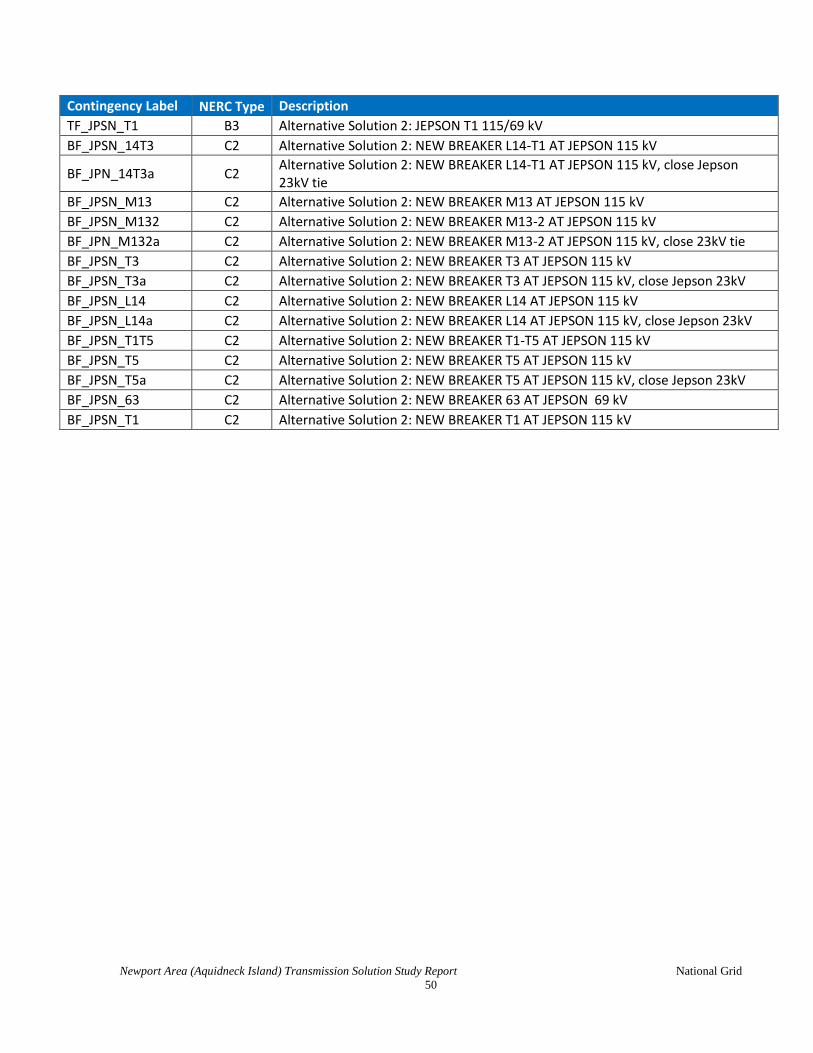
Newport Area (Aquidneck Island) Transmission Solution Study Report National Grid
50
Contingency Label NERC Type Description
TF_JPSN_T1 B3 Alternative Solution 2: JEPSON T1 115/69 kV
BF_JPSN_14T3 C2 Alternative Solution 2: NEW BREAKER L14-T1 AT JEPSON 115 kV
BF_JPN_14T3a C2 Alternative Solution 2: NEW BREAKER L14-T1 AT JEPSON 115 kV, close Jepson 23kV tie
BF_JPSN_M13 C2 Alternative Solution 2: NEW BREAKER M13 AT JEPSON 115 kV
BF_JPSN_M132 C2 Alternative Solution 2: NEW BREAKER M13-2 AT JEPSON 115 kV
BF_JPN_M132a C2 Alternative Solution 2: NEW BREAKER M13-2 AT JEPSON 115 kV, close 23kV tie
BF_JPSN_T3 C2 Alternative Solution 2: NEW BREAKER T3 AT JEPSON 115 kV
BF_JPSN_T3a C2 Alternative Solution 2: NEW BREAKER T3 AT JEPSON 115 kV, close Jepson 23kV
BF_JPSN_L14 C2 Alternative Solution 2: NEW BREAKER L14 AT JEPSON 115 kV
BF_JPSN_L14a C2 Alternative Solution 2: NEW BREAKER L14 AT JEPSON 115 kV, close Jepson 23kV
BF_JPSN_T1T5 C2 Alternative Solution 2: NEW BREAKER T1-T5 AT JEPSON 115 kV
BF_JPSN_T5 C2 Alternative Solution 2: NEW BREAKER T5 AT JEPSON 115 kV
BF_JPSN_T5a C2 Alternative Solution 2: NEW BREAKER T5 AT JEPSON 115 kV, close Jepson 23kV
BF_JPSN_63 C2 Alternative Solution 2: NEW BREAKER 63 AT JEPSON 69 kV
BF_JPSN_T1 C2 Alternative Solution 2: NEW BREAKER T1 AT JEPSON 115 kV

Newport Area (Aquidneck Island) Transmission Solution Study Report National Grid
51
Section 14 Appendix F: N-1 Contingency Results
Monitored Element Pre-Project Alternative Sol. 1 Alternative Sol. 2
Contingency % LTE
Contingency % LTE Contingency % LTE
Dexter T361 (118177 - 118180)
LTE Rating: 130 MVA LN_3762 112 - <90 - <90
Dexter T62 (118178 - 118183)
LTE Rating: 65 MVA LN_3761 112 - <90 - <90
Dexter T63 (118178 - 118183)
LTE Rating: 65 MVA LN_3761 112 - <90 - <90
Line 61 Dexter - Jepson
(118180 - 118181) LTE Rating: 98 MVA
Alt. 1: LTE Rating: 220 MVA
Alt. 2: LTE Rating: 290 MVA
LN_L14 153 - <90 - <90
Line 62 Dexter - Jepson
(118183 - 118181) LTE Rating: 98 MVA
Alt. 1: LTE Rating: 220 MVA
Alt. 2: LTE Rating: 290 MVA
LN_M13 154 - <90 - <90
Jepson Breaker 7 BF_JPSN_3765 154 N/A N/A N/A N/A
Jepson Breaker 9 BF_JPSN_3765 192 N/A N/A N/A N/A
Line 63 Jepson - Navy
(118181 - 118179) LTE Rating: 78 MVA
BF_JPSN_3769 102* BF_JPSN_T5 103* BF_JPSN_M132 105*
*This overload will be mitigated by removing the conductor clearance limitations on two spans of
Line 63. The mitigation involves re-arranging distribution facilities.