new method of capacitors failure detection and...
TRANSCRIPT

New Method of Capacitors Failure Detection andLocation in Shunt Capacitor Banks
H. Jouybari-MoghaddamDepartment of Electrical
and Computer EngineeringWestern University, London, ON, Canada
Tarlochan SidhuThe University of Ontario
Institute of TechnologyOshawa, ON, Canada
Ilia VolohGE Grid Solutions
Markham, ON, [email protected]
Mohammad ZadehETAP
Irvine, CA, [email protected]
Abstract—To achieve more reliable grid it is crucial forutilities to expedite the repair process of critical assets, includingShunt Capacitor Banks (SCBs). Exposure to sharp temperaturevariations, transient over voltages, aging and manufacturingdefects can cause internal failures of capacitor elements. A newmethod using indicating quantity Superimposed Reactance (SR),is presented in this paper to locate capacitor elements failures inShunt Capacitor Banks. The proposed quantity is estimated usingavailable measurements to the unbalance protection functionof SCBs numerical protective relays. The proposed SR adoptscalibrating factors for fault location and can provide live reportof the number of failed capacitor elements. The proposed methodbenefits are: Rapid identification of the SCBs failed elementsfor fuseless and internally fused designs, Determining failureand faulted phase of single-wye connected banks, Ability todetect consecutive failures, even in the same or different phasesdue to self-tuning, Online reporting of elements failure forproactive maintenance planning. The developed method supportsthree different grounding arrangements, wye-ungrounded, wye-grounded via a low ratio current transformer, and wye-groundedvia a grounding capacitor at the SCB neutral point. Compre-hensive simulation and fault-location analysis using PSCAD andMATLAB have verified the proposed algorithm performance.Advantages of the proposed method reports over conventionalunbalance relaying alarms are also demonstrated using a relaytest results comparison.
I. INTRODUCTION
Capacitor units for high voltage power system applicationsincorporate different designs, this includes externally fused,internally fused, and fuseless technologies. Reliability andtotal life cycle cost issues have resulted in higher interest in thelatter two designs for substation applications [1], [2]. Althoughinternally fused and fuseless capacitor units have higher avail-ability, they lack the advantage of having the outward externalfuse to identify the failed units. With unbalance being a majoroccurrence [3], developing methods for determining the failedelements’ phase is an enhancement for Shunt Capacitor Banks(SCBs) numerical protection and control relays. This helps thecrew by often localizing the problem of fault location to aparticular phase for repairing and preparing the bank fasterfor operation. In addition, a detailed event report would beuseful for condition-based maintenance, and it would reduce
An earlier version of this paper has been accepted for publication in IEEETransactions on Smart Grid, ”Shunt Capacitor Banks Online Monitoring Usinga Superimposed Reactance Method” doi: 10.1109/TSG.2017.2690643
unscheduled outages of the SCBs. Fault location could beinherent within unbalance protection schemes based on thelevel of selectivity they provide [4]. Accordingly, except forconfigurations and protection methods that utilize per-phasemeasurements [2], [5], [6], it is challenging for commonunbalance protection functions to incorporate fault locationindication, which is because of the less than ideal number ofavailable measurements.
In the area of fault location and online monitoring of SCBsvery little research work has been reported in the literature,particularly for the unbalance protection methods intended forthis paper. Present methods in the literature can be categorizedinto two types. First the methods that consider faulted phaseand section detection that pertain to double wye banks andare based on neutral current measurements. This categoryincludes the method of [7] that employs vectorial step changein the unbalance current for fault location detection. Thisreference uses successive measurements to detect number offailed elements and consecutive failures in double-wye SCBs.In [8] these methods have been reviewed, and a fault locationapproach has been presented that enhances the outcome ofother schemes that deploy current based unbalance relaying.
In regard to previous works that determine the faulted phasefor single wye SCBs, which would be in relation to theintended configurations in this paper, the method discussedin [9]–[11], utilizes neutral voltage unbalance protection op-erating voltage [12] for single wye ungrounded banks faultlocation. Since the operating voltage is not per-phase, itsphase angle is referenced to the positive sequence bus voltagephase angle and the faulted phase is determined based onthis comparison. Selection of this angle reference disregardsthe contribution of negative sequence voltage on the phaseangle of phase voltages. The method of [13] explains acompensated negative sequence current measure and uses theangular relationship of it to the positive sequence voltage forfault location in wye connected SCBs. This method utilizesboth three phase voltages and currents. To complete the review,a method comparison table is provided in Section III of thepresent paper on these literature and the proposed method.
In the proposed method of this paper, a new element failureindicating quantity is devised that estimates the per unit changein the reactance of each phase. This unbalance quantity is
1

referred to as Superimposed Reactance (SR) and is calculatedbased on available voltages to the unbalance relay. Its phaseangle, per se, is monitored for faulted phase determinationi.e., no referencing is required for the proposed phase anglemonitoring. The proposed principle presents straight forwardcalculation of the reference index for estimating numberof failed elements. Further, the proposed SR based onlinemonitoring method is capable of updating calibrating factorsfor maximum sensitivity [14]. The calibrating factors arederived using k-factors and the measured voltage inputs ofthe unbalance relay. The updating property enables detectingconsecutive failures, which prevents from successive failuresbeing masked, and mitigates capacitance gradual changes [8]for element failure monitoring purpose. The proposed methodoutcomes can help to activate advance alarms due to elementfailures inside capacitor units [15] and further, to understandevolution of the failures for root cause analysis, regardless ofthe unit design. The presented algorithm is developed for threeconfigurations: ungrounded wye, wye grounded through acapacitor at the neutral point, and wye grounded via a low ratiocurrent transformer. The rest of the paper includes followingsections: Section II presents the proposed online monitoringmethods; proposed methods verification and method compar-ison are provided in Section III.
II. PROPOSED SUPERIMPOSED REACTANCE METHOD
The primary protection scheme for HV SCBs internalfailures is unbalance protection [16]. Based on availablemeasurements for the typical unbalance protection type foreach configuration, a new way of estimating the change in theaffected phase’s reactance is presented. The bank connectionsand their respective unbalance protection methods are selectedfrom IEEE Std C37.99 [17]. It is worth noting that config-urations protected by per phase voltage differential are notincluded in this study because per phase protection inherentlydetermines the faulted phase. Throughout the circuit analysisin this paper the capacitor bank impedances are assumedas capacitive reactances [4], [17] and electrical quantitiesrepresent phasors. Furthermore, the zero sequence voltage iscalculated using three phase measured voltages.
A. Ungrounded Wye Connected SCB
Fig. 1 (a) depicts the utilized voltages for unbalance protec-tion of this connection, where VP denotes the three phase busvoltages, i.e. P represents phase A, B or C. The neutral voltagewill shift when an element develops a fault. To estimate theneutral voltage, Kirchhoff’s Current Law (KCL) is appliedto the neutral node. We assume the failure is in phase A,and phase reactance for the faulted phase after the failure isdenoted by Xpf . By denoting reactance ratios as follows:
KAB = XA
XB
KAC = XA
XC
(1)
N
XA XB XC
A
B
C
VN
VP
IG
RXN VN VR
N N
(a)(b) (c)
Fig. 1. Wye-Connected SCBs (a) Ungrounded (b) Grounded via Capacitor(c) Grounded via CT.
and defining the per unit change in the reactance as Superim-posed Reactance (SR); denoted in general by
XSpup =
Xp
Xpf− 1 =
Xp −Xpf
Xpfp : A,B or C (2)
a simplified element failure indicating quantity can be derived:
VN =VAX
SpuA + VA + (KA
BVB − VB::
) + VB::
XSpuA + 1 +KA
B +KAC
+
+(KA
CVC − VC) + VC
XSpuA + 1 +KA
B +KAC
− V0::
+ V0::
(3)
For the equation that can estimate the SR, (3) is re-written andexpressed by deploying the following notations representingthe unbalance (calibrating) factors:
λA = 1 +KAB +KA
C (4)
γA = (KAB − 1)(VB − V0) + (KA
C − 1)(VC − V0) (5)
SR will be monitored for both magnitude and phase anglefor all of the phases. Since assumption of failure in the otherphases gives analogous results, the general form for (3) canbe expressed as
(XSpup + λp)(VN − V0) = (Vp − V0)XSpu
p + γp (6)
which implies
XSpup =
γp − λp(VN − V0)
VN − Vp(7)
Apparently, the corresponding reactance ratios for phase Band C are either reciprocal or ratios of the terms in (1), thusit is expected that all three phase’s SRs get affected upon aninternal failure.
Equation (7) is an indirectly measured equivalent for the SRand, as per the SR definition in (2), the expected magnitudeand phase angle for this equivalent is known using the ratedSCB values. Accordingly, for fuseless SCBs the weld at thepoint of failure shorts out the faulty element/group and forinternally fused SCBs the failed element is disconnected by
2

its fuse. As a result, the faulted phase post-fault capacitivereactance would be less than its pre-fault value for fuselessSCBs, and the reverse is true for internally fused SCBs. Theelement failure indicating quantity would become a uniqueterm for both fusing technologies when an adjuster factor isincorporated into (7). This factor is defined as
Kadj =
+1 for fuseless banks−1 for fused banks
(8)
The resultant SR is expressed in (9).
XSpup = Kadj
γp − λp(VN − V0)
VN − Vp(9)
Kadj definition is intended to be such that the explainedchanging trend in reactances ensures a positive value for XSpu
p
as per (2). Therefore, phase angle of XSpup is expected to
be close to zero for the faulted phase. Evaluation of this isreferred to as ”phase-angle checking” throughout this paper.In algorithm settings a 15 [9] detection zone around thezero degree is considered to increase the proposed methodsreliability.
Setting and Updating of Parameters: In addition to voltagephasors, the proposed online monitoring method requires thevalues of γp and λp. These parameters are dependent on thek-factors; thus, setting the k-factors leads to deriving them.The following procedure is considered for this purpose. Forthe sake of brevity assume it is required to calculate phase Ak-factors, for simplification reason, the reactance of phase Ais accommodated in the KCL balance equation written for theneutral node. By using the k-factor notations one can derive:
(VB − VN )KAB + (VC − VN )KA
C = VN − VA (10)
Real and imaginary parts of (10) are used to calculate the twok-factors. The equation sets for phase B and C are analogousto (10).
B. Wye-Connected SCB grounded through a Capacitor
In this particular configuration, a capacitive impedancegrounds the common neutral of the phases. Fig. 1 (b) showsthe measurement inputs to unbalance protection function em-ployed for this SCB connection. Applying KCL at the neutralpoint of the SCB, with a presumed internal failure in phaseA, and doing some algebra will reintroduce the SR as per (2).The phase reactance ratios (k-factors) are defined similar to(1), along with a third k-factor introduced for each phase bythe following definition:
KpN =
Xp
XNp : A,B or C (11)
Applying the SR and k-factors notations expresses the follow-ing identity
VAXSpuA + 3V0 + VB (KA
B − 1) + VC (KAC − 1)
= VN (1 +KAB +KA
C +KAN +XSpu
A ) (12)
Adding and subtracting three terms of KAp V0 for the three
k-factors helps to draw an analogy between (12) and the
proposed principle for ungrounded banks as per (7). As aresult, the following unbalance factors can be symbolized tosimplify the SR equation:
γ′
A = (KAB − 1)(VB − V0) + (KA
C − 1)(VC − V0) (13)
λ′
A = 1 +KAB +KA
C +KAN (14)
Comparing with the terms derived for ungrounded wye SCBs,as per (4) and (5), the following relations can be concluded:
γ′
p = γp
λ′
p = λp +KpN
(15)
By applying the equivalent terms, the element failure indicat-ing quantity would become:
XSpup =
γ′
p − λ′
p(VN − V0) −KpNV0
VN − Vp(16)
Similar to ungrounded SCBs an adjuster factor will also beapplied.
Setting and Updating of Parameters: To derive the self-setting equations, KCL is applied at the neutral point of theSCB shown in Fig. 1 (b) and results in the following balanceequation:
VN (1 +KAN )− VA = KA
B (VB − VN ) +KAC (VC − VN ) (17)
As can be seen, the number of k-factors is three but onlytwo equations, i.e. real and imaginary segments of (17), existfor deriving them (all of the k-factors are real numbers rep-resenting reactance ratios). Accordingly, since the groundingcapacitive reactance is smaller than phase equivalent capacitivereactance, the Kp
N would be much larger than the phase k-factors, which are normally about unity. Based on the neutralcapacitor and the phase capacitor values [18], a typical phaseto neutral k-factor would be around 10. As a result, even withelement failures development in any of the three phases thechange in the third k-factor from its pre-set value would betrivial, and thus it is assumed that this k-factor is constant forthe faulted phase determination purpose, i.e. there is no needto update this quantity once it is set based on rated capacitorvalues. It should be noted that according to IEEE Std C37.99[17], the ratio of phase reactance to grounding reactance(the third k-factor) does also appear as a ratio compensationproperty in the operating voltage for neutral voltage unbalanceprotection of this configuration and it is set constant using thecapacitor rated values.
C. Wye-Connected SCB grounded through a CT
Fig. 1 (c) illustrates the common measurements for un-balance protection of this configuration. Faults will causeresidual current to flow through the low ratio grounding CTand the resistive burden will develop an associated voltage,VR. For the sake of simplicity, a CT ratio (CTR) equal to theresistive burden is assumed [17]. This way, VR and the primaryground current (IG) values can be equivalently expressed inthe equations.
IG =VRR
CTR (18)
3

To derive the element failure indicating quantity, first, KCL isapplied at the neutral point. An internal failure is consideredin phase A. With the same definition for the SR as per (2),and the k-factors as per (1), the rearranged balance equationwould be
VB(KAB − 1) + VC(KA
C − 1) +
+VA(XSpuA ) + 3V0 = −jXAVR (19)
In (19), the before failure phase reactance, XA, can beapproximated with its rated value, denoted by X . In termsof algorithm reliability, the applicability of this assumptionfor consecutive failures will be investigated in Section III.Nevertheless, this assumption is considered to be acceptable asthe rated reactance is similarly applied in the operating voltageof the corresponding protection method defined in IEEE StdC37.99 [17]. To give an example, for a 230 kV, 84.37 MvarSCB with a value of 627 Ω for X , a change of less than0.1% after an element failure and less than 1.8% upon a unitfailure was observed in the phase reactance. Therefore, evenfor detecting consecutive failures the assumption should stillhold true.Assuming a failure in phase A, the SR can be calculated asfollows using (19)
XSpuA =
VA + VB KAB + VC K
AC + jXVR
−VA(20)
The SR calculation equation for phase B and C would besimilar with only changing the corresponding k factors andphase voltages. Similar to ungrounded SCBs an adjuster factorwill also be applied.
Setting and Updating of Parameters: For self-setting ofthe k-factors, (20) has to be evaluated prior to an internalfailure, i.e. when Xpf = Xp, this causes the left side of (20),the associated SR, to become zero. Therefore, the real andimaginary segments of the following identity can be solvedfor finding the two k-factors (reactance ratios):
KABVB +KA
CVC = −jXVR − VA (21)
The equation sets for phase B and C are analogous to (21).
D. Estimating the Number of Failed Elements
A property of the proposed SR based methods is the inherentreference index that they provide for detecting number offailed elements. The per unit change in the phase reactancewith development of a single element failure can be calculatedstraightforwardly using (2). Unit and phase arrangement (num-ber of series and parallel connections, ratings of elements andthe bank) are the required information for estimating pre-faultand post-fault phase reactances. Utilizing (2), these quantitiesgive the threshold and reference index for the SR magnitudeevaluation. It is worthy to note that as the proposed SR is aper unit quantity, the thresholds are not susceptible to agingof the capacitors. The SR ratio to this reference index helpsto estimate number of failed elements. Note that dependent onthe configuration, the SR is estimated by either (7), or (16),or (20).
Fig. 2. Flowchart of the proposed SR based online monitoring method.
E. Block Diagram of the SR Based Online Monitoring Method
Fig. 2 depicts the proposed SR based online monitoringflowchart. For the proposed application integration, the en-abled unbalance protection in a multi-functional SCB relayshould be the ”neutral voltage unbalance”. The protectedcapacitor bank’s grounding and fusing type should also beconfigured in the unbalance protection menu of the relay. Thiswill activate the corresponding SR equation for element failuremonitoring purpose. The proposed online monitoring algo-rithm considers SR magnitude thresholds, SR angle checking,calibration of compensating factors, and a counting technique[8] for security and dependability of the method. Unbalancefactors calibration addresses impacts of unbalance sourcesother than element failures, including partial shading and aging[19]. As it will be shown in the next section, balancing out(zeroing) SR magnitude before capacitor failure instant andafter detecting/recording the failure, verifies the effectivenessof the compensation in presence of system voltage unbalanceand pre-existing capacitance unbalance. Also the ability toidentify successive element failures is the consequence of k-factor updating property. Accordingly, it is important to applyperiodic (regular) update of k-factors besides updating themeach time a failure is detected [8]. Due to different rates andtime scale of gradual changes, it has been reported that theperiodic updating will suffice for algorithm reliability [14].Blocking provision for avoiding periodic update interferencewith faulted phase determination is also considered [8].
With reference to (2), in part of the algorithm, the SR phaseangle is checked and is expected to be in the zero anglezone for the affected phase. When number of failures is alsoestimated, based on the corresponding magnitude of the SR,the counting scheme finally asserts the outputs. The process iscompleted by resetting the SR with recalculation (updating)the unbalance factors. This can also be seen illustrated inFig. 3, in which the magnitude and phase angle of the SR
4

Time
Angle Zone
Magnitude Threshold
Capacitor Element(s) Failure
Fault Location Determined; SR Reset Applied
Counting Scheme Angle
Mag.
Fig. 3. Graphical guide to the proposed SR method decision principle foreach phase.
100 MVA
230 KV 50 km 50 km
SCB
Feeder
Fig. 4. Single line diagram of the simulated system in PSCAD [8].
are plotted vs time. The time-tagged capacitor element failurerecords would also be accessible as part of fault reports sent bySCB protection IED to HMI/SCADA through communicationprotocols.
III. PERFORMANCE VERIFICATION OF THE PROPOSEDONLINE MONITORING METHOD
Fundamental phasors of the required voltage/currents arecalculated using full cycle Discrete Fourier Transform (DFT).The developed algorithm involves anti-aliasing filters [8],Capacitor Voltage Transformer (CVT) transient filter and de-caying DC removal filter. The SR based indicating quantityevaluations are executed at each protection pass, which istypically 16 times per cycle [18]. The PSCAD simulationsare performed for Fig. 4 power system where Figures 5 and6 SCBs are considered in evaluating the SR based onlinemonitoring scheme. For the grounded configurations the bankand unit designs were also the same as these depicted SCBs.The grounding capacitor is selected based on the referencedratio in Section II-B. Simulations have considered harmonicvoltage distortion, unbalanced load, assumed measurementnoise, and pre-existing unbalance in the banks [8]. Further tothe presented simulation results in this paper, the proposedmethod has been also verified for other accuracy concernssuch as beyond the limits system unbalance, the instrumenttransformers’ characteristics and ratio error. In such cases,apart from reliable performance because of calibrating factors,the subtraction in the SR definition, as per (2), negates theimpact of common measurement error sources.
The expected outcome for the proposed SR-based onlinemonitoring scheme is to determine capacitor element failureslocations according to their time of occurrence and to recordestimated number of failed elements each time. The calculatedSR is per phase, thus in the outcome figures three plots arepresented to increase the clarity. Also double or single arrowsin figures will identify element failures, dependent on the
62 ...
...
...
14
3
1.36F
2
...
..
Unit
Fig. 5. 230 kV internally fused ungrounded Y-connected SCB.
12
5
...
1
6
60.8F...
......
...
...
Unit
Fig. 6. 230 kV fuseless ungrounded Y-connected SCB.
number of failures. It is worth noting that short simulationintervals are intentional to demonstrate successful detectionof semi-simultaneous failures. This is a crucial algorithmproperty because it prevents missing the failures when theymight cancel each other’s impact on the operating signal–hereafter we refer to this as ambiguous failure conditions [17].
A. Ungrounded Wye-Connected SCB
Fig. 7 demonstrates variations in the SR and the proposedmethod output for an internally fused SCB. The simulatedscenario includes the following events, which are successfullydetected as illustrated in Fig. 7.
• Single element failure in phase A at 0.2 s• Multiple element failure in phase B at 0.25 s• Consecutive failure in phase A at 0.3 s• Multiple element failure in phase C at 0.35 s
Table I shows each step of the proposed online monitoringprocedure and corresponds to the above scenario. Similarprocedure can be verified for the internal failure records ofother scenarios demonstrated in this paper. It is worthwhile tonote that the applied short pick up delay is for demonstrationpurpose only and actual pick up delays in the range of secondshave to be considered in practice.
TABLE IFAILURE DETECTION STEPS, SCENARIO OF FIG. 7.
Capacitor Phase with Magnitude Pickup OperandFailure Activated Ratio Delay UpdateInstant Angle Zone To Ref. Passed Instant0.2 s A 1 X 0.247 s0.25 s B 2 X 0.295 s0.3 s A 1 X 0.348 s0.35 s C 2 X 0.401 s
5

0.2 0.25 0.3 0.35 0.4−180
0
180(a) Phase A
Ang
le (
Deg
.)
0
0.2
0.4
0.6
0.8
% M
agni
tude
Angle Magnitude
0.2 0.25 0.3 0.35 0.4−180
0
180 Phase B
Ang
le (
Deg
.)
0
0.2
0.4
0.6
0.8
% M
agni
tude
0.2 0.25 0.3 0.35 0.4−180
0
180 Phase C
Ang
le (
Deg
.)
0
0.2
0.4
0.6
0.8
% M
agni
tude
0.2 0.25 0.3 0.35 0.40
1
2
3(b)
Num
ber
Time (s)
A B C
Fig. 7. Internal failures record for an ungrounded SCB (a) the proposedSR magnitude and angle variations. (b) faulted phase and number of failedelements.
0.2 0.25 0.3 0.35 0.4−180
0
180(a) Phase A
Ang
le (
Deg
.)
0
0.2
0.4
0.6
0.8
% M
agni
tude
Angle Magnitude
0.2 0.25 0.3 0.35 0.4−180
0
180 Phase B
Ang
le (
Deg
.)
0
0.2
0.4
0.6
0.8
% M
agni
tude
0.2 0.25 0.3 0.35 0.4−180
0
180 Phase C
Ang
le (
Deg
.)
0
0.2
0.4
0.6
0.8
% M
agni
tude
0.2 0.25 0.3 0.35 0.40
1
2
3
(b)
Num
ber
Time (s)
A B C
Fig. 8. Internal failures record for a SCB grounded through low voltagecapacitor (a) the proposed SR magnitude and angle variations. (b) faultedphase and number of failed elements.
B. Wye Connected SCB grounded through a capacitor
Fig. 8 presents the variations in the SR and the proposedmethod output for a fuseless SCB. As a result, reliabledetection of the faulted phase and number of failed elementsfor the following events is verified:
• Single element failure in phase B at 0.2 s• Multiple element failure in phase A at 0.24 s• Single element failure in phase C at 0.3 s• Consecutive failure in phase C at 0.35 s
0.2 0.25 0.3 0.35 0.4 0.45−180
0
180(a) Phase A
Ang
le (
Deg
.)
0
0.2
0.4
0.6
0.8
% M
agni
tude
Angle Magnitude
0.2 0.25 0.3 0.35 0.4 0.45−180
0
180 Phase B
Ang
le (
Deg
.)
0
0.2
0.4
0.6
0.8
% M
agni
tude
0.2 0.25 0.3 0.35 0.4 0.45−180
0
180 Phase C
Ang
le (
Deg
.)
0
0.2
0.4
0.6
0.8
% M
agni
tude
0.2 0.25 0.3 0.35 0.4 0.450
1
2
3(b)
Num
ber
Time (s)
A B C
Fig. 9. Internal failures record for a SCB grounded via CT (a) the proposedSR magnitude and angle variations. (b) faulted phase and number of failedelements.
10:00 11:00 12:00 13:00 14:00 15:00 16:00 17:00−180
0
180
Angl
e (D
eg.)
Time of Day
0
0.2
0.4
0.6
0.8
% M
agni
tude
Mag. Angle
Fig. 10. Unbalance factors periodic updating impact on the operating quantity.
C. Wye Connected SCB grounded through a CT
Fig. 9 shows the SR variations for the following simulatedscenario performed for an internally fused SCB. The failuresare properly detected as shown in this figure.
• Single element failure in phase C at 0.2 s• Multiple element failure in phase A at 0.3 s• Consecutive failure in phase C at 0.4 s
D. The Periodic Updates Effectiveness Demonstration
Because the resultant unbalance from unequal heating takesplace over an interval of several hours, in contrast to theunbalance resulting from element failures, our demonstrationfor the periodic updates effectiveness has to be illustrative.Therefore, similar to the verification approach presented in [8],[20], in an illustrative scenario it is assumed that in one of thephase capacitances a linear change takes place over-time. Fig.10 presents the superimposed reactance variations trend dueto the simulated linear capacitance change during 7 hours inday time. Arrows signify the instants of periodic reset. As canbe seen, at the moments that the periodic updating is appliedit has kept the SR angle out of the angle zone and also hasreset the SR magnitude, thus ensuring algorithm security.
6

E. Investigation of Susceptibility to System Faults
Several simulations were performed to discover whetherfailures that occur during power system faults are detectableand countermeasures to maintain the proposed online mon-itoring methods reliability are introduced. Simulations showthat dependent on the severity of the system faults, themagnitude of the SR can change abruptly to hundred timesof its change for a single element failure. Jumps due to thewhole elements failure in a single unit are much smallerthan this, e.g. 20 times a single element failure. The exactvalues depend on number of elements and unit construction,i.e. number of series/parallel connections. Further, the neutralvoltage (for ungrounded SCBs) and the ground current (forSCBs grounded via CT) change drastically upon occurrenceof system disturbances, causing unpredictable variations bothin angle and magnitude of the SR. Therefore, in presence ofsystem faults the element failure monitoring for these twoconfigurations is susceptible to malfunction. To address this inthe corresponding proposed algorithms, an upper limit is setfor the SR magnitude to ensure that the variations are suspectof element failures and to disable the proposed function untilthe power system fault is cleared. In actual implementations,blocking the proposed function for capacitor protection relaycan be done via time delays, communication with a systemprotective relay or supervision from other protection elementswithin a multi-functional numerical capacitor bank relay. Thesusceptibility is much less for banks that are grounded viaa low voltage capacitor because the measured neutral pointvoltage is across the grounding capacitor, and thus in normaloperating conditions (no system faults) it is much greater thanthe normally close to zero ground current/neutral voltage ofthe two other configurations.The following selected scenarios are illustrative examples fromsimulation cases that were carried out. Fig. 11 illustratesevaluation outcomes for an internally fused ungrounded SCB.In the corresponding scenario, a phase B (SCB bus) to groundfault occurs at 0.22 s and lasts for 100 ms, meanwhile twoelements fail in the same phase at 0.25 s. Results provereliable operation of the proposed method, while taking intoaccount the blocking option. It is worthy to note that duringthe presence of the shunt fault to ground the SR magnitudehas gone far beyond the shown area in Fig. 11.For SCBs grounded via a low voltage capacitor, a fuseless
bank is chosen to simulate a case in which at 0.22 s an internalfailure in Phase A and an open pole in the same phase occursimultaneously. For the sake of clarity of the illustrations ashort dead-time has been considered for this series fault, i.e.the event lasts 100 ms. Fig. 12 shows the successful elementfailure detection once the external unbalance is cleared. Asexplained before, applying a magnitude upper limit is notnecessary for faulted phase determination of this configuration.A special scenario is presented that evaluates the element
failure monitoring for banks grounded via CT. All elementsof a unit fail in phase A at 0.2 s then at 0.26 s a phase tophase fault (A-C) with 50 ms duration is simulated. At 0.3
0.2 0.25 0.3 0.35 0.4 0.45−180
0
180(a) Phase A
Ang
le (
Deg
.)
00.20.40.60.8
% M
agni
tude
Angle Magnitude
0.2 0.25 0.3 0.35 0.4 0.45−180
0
180 Phase B
Ang
le (
Deg
.)
00.20.40.60.8
% M
agni
tude
0.2 0.25 0.3 0.35 0.4 0.45−180
0
180Phase C
Ang
le (
Deg
.)
00.20.40.60.8
% M
agni
tude
0.2 0.25 0.3 0.35 0.4 0.450123
(b)
Num
ber
Time (s)
A B C
Blocked (Excessive Mag.)
Fig. 11. Internal failures record for external unbalance case study, ungroundedSCB (a) the proposed SR magnitude and angle variations. (b) faulted phaseand number of failed elements.
0.2 0.25 0.3 0.35 0.4 0.45−180
0
180(a) Phase A
Ang
le (
Deg
.)
00.20.40.60.8
% M
agni
tude
Angle Magnitude
0.2 0.25 0.3 0.35 0.4 0.45−180
0
180Phase B
Ang
le (
Deg
.)
00.20.40.60.8
% M
agni
tude
0.2 0.25 0.3 0.35 0.4 0.45−180
0
180Phase C
Ang
le (
Deg
.)
00.20.40.60.8
% M
agni
tude
0.2 0.25 0.3 0.35 0.4 0.450
1
2
3
(b)
Num
ber
Time (s)
A B C
Fig. 12. Internal failures record for external unbalance case study, SCBgrounded via capacitor (a) the proposed SR magnitude and angle variations.(b) faulted phase and number of failed elements.
s, another single element failure takes place in phase A. Fig.13 shows the SR variations along with the successful onlinemonitoring output for this phase. This outcome also confirmsthe discussed assumption in Section II-C.
F. Application to Externally Fused SCBs
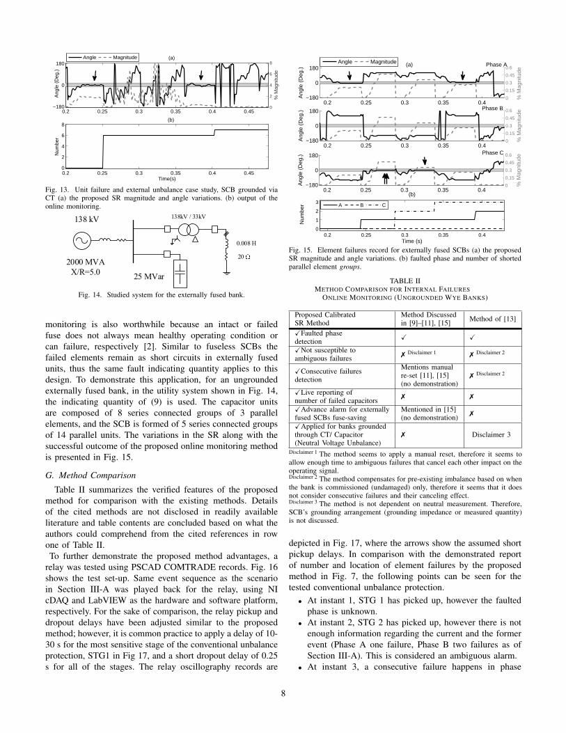
Cascading element failures is more common for externallyfused SCBs, although they have failed units visual indication[21]; therefore, there is a perceived application for fuse saving[15] in this power capacitor design. Element failures online
7
0.2 0.25 0.3 0.35 0.4 0.45−180
0
180(a)
Ang
le (
Deg
.)
0
2
4
6
8
% M
agni
tude
Angle Magnitude
0.2 0.25 0.3 0.35 0.4 0.450
2
4
6
8(b)
Num
ber
Time(s)
Fig. 13. Unit failure and external unbalance case study, SCB grounded viaCT (a) the proposed SR magnitude and angle variations. (b) output of theonline monitoring.
2000 MVA
X/R=5.0
138 kV 138kV / 33kV
25 MVar
20
0.008 H
Fig. 14. Studied system for the externally fused bank.
monitoring is also worthwhile because an intact or failedfuse does not always mean healthy operating condition orcan failure, respectively [2]. Similar to fuseless SCBs thefailed elements remain as short circuits in externally fusedunits, thus the same fault indicating quantity applies to thisdesign. To demonstrate this application, for an ungroundedexternally fused bank, in the utility system shown in Fig. 14,the indicating quantity of (9) is used. The capacitor unitsare composed of 8 series connected groups of 3 parallelelements, and the SCB is formed of 5 series connected groupsof 14 parallel units. The variations in the SR along with thesuccessful outcome of the proposed online monitoring methodis presented in Fig. 15.
G. Method Comparison
Table II summarizes the verified features of the proposedmethod for comparison with the existing methods. Detailsof the cited methods are not disclosed in readily availableliterature and table contents are concluded based on what theauthors could comprehend from the cited references in rowone of Table II.To further demonstrate the proposed method advantages, a
relay was tested using PSCAD COMTRADE records. Fig. 16shows the test set-up. Same event sequence as the scenarioin Section III-A was played back for the relay, using NIcDAQ and LabVIEW as the hardware and software platform,respectively. For the sake of comparison, the relay pickup anddropout delays have been adjusted similar to the proposedmethod; however, it is common practice to apply a delay of 10-30 s for the most sensitive stage of the conventional unbalanceprotection, STG1 in Fig 17, and a short dropout delay of 0.25s for all of the stages. The relay oscillography records are
0.2 0.25 0.3 0.35 0.4−180
0
180(a) Phase A
Ang
le (
Deg
.)
0
0.15
0.3
0.45
0.6
% M
agni
tude
Angle Magnitude
0.2 0.25 0.3 0.35 0.4−180
0
180 Phase B
Ang
le (
Deg
.)
0
0.15
0.3
0.45
0.6
% M
agni
tude
0.2 0.25 0.3 0.35 0.4−180
0
180 Phase C
Ang
le (
Deg
.)
0
0.15
0.3
0.45
0.6
% M
agni
tude
0.2 0.25 0.3 0.35 0.40
1
2
3
(b)
Num
ber
Time (s)
A B C
Fig. 15. Element failures record for externally fused SCBs (a) the proposedSR magnitude and angle variations. (b) faulted phase and number of shortedparallel element groups.
TABLE IIMETHOD COMPARISON FOR INTERNAL FAILURES
ONLINE MONITORING (UNGROUNDED WYE BANKS)
Proposed Calibrated Method Discussed Method of [13]SR Method in [9]–[11], [15]XFaulted phase
X XdetectionXNot susceptible to
7 Disclaimer 1 7 Disclaimer 2ambiguous failures
XConsecutive failures Mentions manual7 Disclaimer 2
detection re-set [11], [15](no demonstration)
XLive reporting of7 7number of failed capacitors
XAdvance alarm for externally Mentioned in [15]fused SCBs fuse-saving (no demonstration) 7
XApplied for banks grounded7 Disclaimer 3through CT/ Capacitor
(Neutral Voltage Unbalance)Disclaimer 1 The method seems to apply a manual reset, therefore it seems toallow enough time to ambiguous failures that cancel each other impact on theoperating signal.Disclaimer 2 The method compensates for pre-existing imbalance based on whenthe bank is commissioned (undamaged) only, therefore it seems that it doesnot consider consecutive failures and their canceling effect.Disclaimer 3 The method is not dependent on neutral measurement. Therefore,SCB’s grounding arrangement (grounding impedance or measured quantity)is not discussed.
depicted in Fig. 17, where the arrows show the assumed shortpickup delays. In comparison with the demonstrated reportof number and location of element failures by the proposedmethod in Fig. 7, the following points can be seen for thetested conventional unbalance protection.
• At instant 1, STG 1 has picked up, however the faultedphase is unknown.
• At instant 2, STG 2 has picked up, however there is notenough information regarding the current and the formerevent (Phase A one failure, Phase B two failures as ofSection III-A). This is considered an ambiguous alarm.
• At instant 3, a consecutive failure happens in phase
8

Fig. 16. Unbalance protection test setup (low level injection).
Fig. 17. Relay oscillography records.
A but no change can be found in the relay operands.This shows missing an event. The operating quantity’smagnitude is not proportional to the level of unbalancewhen consecutive failures happen in different phases.
• At instant 4, all of the phases have two failed elements,this is an ambiguous failure scenario and as it can be seenthe operating quantity jumps to the pre-existing unbalancevalue and the picked up functions are reset.
Furthermore, if the pickup delays had been set to their typicalvalue, even the first picked up stage would have been droppedout before it can operate the function output, resulting inmissing all of the internal failures. The mentioned pointsdemonstrate the importance of a per-phase indicating quantitywith automatic re-calibration upon determining each failurefor the purpose of online monitoring.
IV. CONCLUSION
A discriminating principle called Superimposed Reactance(SR) that has the following functionalities for both groundedand ungrounded wye-connected SCBs was presented:
• SR method can be applied to both fuseless or fusedcapacitor banks
• SR method can detect number of failed elements andfaulted phase even when elements failures are cascad-ing. Output of the method is available to the operatingpersonnel in the real time to take measures immediately
• SR method accounts for the bank inherent unbalance,variations in the capacitance due to uneven sun exposure,CT inaccuracies, etc., due to self-tuning
• SR method is immune to the system faults• SR method is capable to provide time stamped event
records for postmortem and root cause analysis
The base value for estimating number of failed elements iscoupled to the proposed element failure indicating quantity,and the proposed method makes the most out of availablemeasurements to record each phases capacitor element fail-ures. This, along with deploying dynamic calibrating factors,prevents from missing detecting the failures that tend to nullifyeach other, which impacts the unbalance quantity. Implement-ing the proposed online monitoring scheme in SCBs protectionIEDs would provide comprehensive fault reports and alarmsthat are vital to utilities for reducing outages in smart grids.Various scenarios simulation has verified the performance, reli-ability and advantages of the proposed superimposed reactancemethod for different applications.
REFERENCES
[1] Eaton’s Cooper Power Systems catalog: Power capacitors, CooperPower Systems, July 2014.
[2] M. Dhillon and D. Tziouvaras, “Protection of fuseless shunt capacitorbanks using digital relays,” in 26th Annual Western Protective RelayConference, October 1999.
[3] K. C. Agrawal, Industrial Power Engineering and Applications Hand-book. MA, USA: Butterworth-Heinemann, 2001.
[4] A. Chaudhary, T. Day, K. Fender, L. Fendrick, and J. McCall, “Pull a fewstrings [complete protection of multistring fuseless capacitor banks],”Industry Applications Magazine, IEEE, vol. 9, no. 6, pp. 34–39, Nov2003.
[5] E. Price and R. Wolsey, “String current unbalance protection and faultedstring identification for grounded-wye fuseless capacitor banks,” in 65thAnnual Georgia Tech Protective Relaying Conference, May 2011.
[6] M. Bishop, T. Day, and A. Chaudhary, “A primer on capacitor bankprotection,” Industry Applications, IEEE Transactions on, vol. 37, no. 4,pp. 1174–1179, Jul 2001.
[7] Z. Gajic, M. Ibrahim, and J. Wang, “Method and arrangement for aninternal failure detection in a y-y connected capacitor bank,” US Patent20 130 328 569, December, 2013.
[8] H. Jouybari-Moghaddam, T. S. Sidhu, M. R. Zadeh, and P. Parikh,“Enhanced fault location scheme for double wye shunt capacitor banks,”IEEE Transactions on Power Delivery, vol. 32, no. 4, pp. 1872–1880,August 2017.
[9] S. Samineni, C. Labuschagne, J. Pope, and B. Kasztenny, “Fault locationin shunt capacitor banks,” in Developments in Power System Protection(DPSP 2010). Managing the Change, 10th IET International Conferenceon, March 2010, pp. 1–5.
[10] S. Samineni, C. Labuschagne, and J. Pope, “Principles of shunt capacitorbank application and protection,” in Protective Relay Engineers, 201063rd Annual Conference for, March 2010, pp. 1–14.
[11] J. Schaefer, S. Samineni, C. Labuschagne, S. Chase, and D. Hawaz,“Minimizing capacitor bank outage time through fault location,” inProtective Relay Engineers, 2014 67th Annual Conference for, March2014, pp. 72–83.
9

[12] B. Kasztenny, J. Schaefer, and E. Clark, “Fundamentals of adaptiveprotection of large capacitor banks - accurate methods for cancelinginherent bank unbalances,” in Protective Relay Engineers, 2007. 60thAnnual Conference for, March 2007, pp. 126–157.
[13] A. Kalyuzhny, J. C. Mccall, and T. R. Day, “Corrective device protec-tion,” US Patent 7 973 537, July, 2011.
[14] B. Kasztenny, D. McGinn, and I. Voloh, “Enhanced adaptive protectionmethod for capacitor banks,” in Developments in Power System Protec-tion, 2008. DPSP 2008. IET 9th International Conference on, March2008, pp. 269–274.
[15] S. Samineni, C. Labuschagne, S. Chase, and J. Hawaz, “Fault locationin capacitor banks:how to identify faulty units quickly and restore thebank to service,” in CIGRE, 21 rue d’Artois F-75008 Paris, France,2014, pp. B3–212.
[16] R. Horton, T. Warren, K. Fender, S. Harry, and C. A. Gross, “Unbalanceprotection of fuseless, split-wye, grounded, shunt capacitor banks,” IEEETransactions on Power Delivery, vol. 17, no. 3, pp. 698–701, Jul 2002.
[17] “IEEE Guide for the Protection of Shunt Capacitor Banks,” IEEE StdC37.99-2012 (Revision of IEEE Std C37.99-2000), pp. 1–151, March2013.
[18] C70 Capacitor Bank Protection and Control System, UR Series Instruc-tion Manual, GE Digital Energy, November 2014.
[19] R. Moxley, J. Pope, and J. Allen, “Capacitor bank protection for simpleand complex configurations,” in Protective Relay Engineers, 2012 65thAnnual Conference for, April 2012, pp. 436–441.
[20] H. Jouybari-Moghaddam, T. S. Sidhu, M. R. Zadeh, and P. Parikh,“Shunt capacitor banks online monitoring using a superimposed re-actance method,” Accepted for IEEE Transactions on Smart Grid,doi:10.1109/TSG.2017.2690643.
[21] T. Ernst, “Fuseless capacitor bank protection,” in Proc. of MinnesotaPower Systems Conf., 1999, pp. 77–83.
V. BIOGRAPHIES
Hessamoddin Jouybari-Moghaddam received the M.Sc. degree in electricalengineering from Amirkabir University of Technology, Tehran, Iran, in 2012,and the Ph.D. degree in electrical and computer engineering from theUniversity of Western Ontario (Western University), London, ON, Canada in2017. He has been the recipient of 2017 graduate student award for excellencein research from the electrical and computer engineering department ofWestern University and his areas of interest include power system protection,monitoring, and automation.
Tarlochan Sidhu (M’90-SM’94-F’04) received the Ph.D. degree in electricalengineering from University of Saskatchewan, Saskatchewan, Saskatoon, SK,Canada, in 1989. He is currently a Professor and Dean of Faculty of Engi-neering and Applied Science at University of Ontario Institute of Technology(UOIT), Oshawa, ON, Canada. Prior to this, he was a Professor and Chairof the Electrical and Computer Engineering Department at the University ofWestern Ontario, London, ON, Canada. He also has held the NSERC/HydroOne Senior Industrial Research Chair in Power Systems Engineering. Hisresearch interests include power system protection, monitoring, control andautomation.
Ilia Voloh (M’99, SM’03) received his Electrical Engineering degree fromIvanovo State Power University, Russia. He is currently consulting engineer-protection with GE Grid Solutions, Markham, ON, Canada. His areas ofinterest are advanced power system protection algorithms and advanced com-munications for protective relaying. Ilia authored and co-authored more than40 papers presented at major North America Protective Relaying conferences.He is a member of IEC TC95 committee, active member of the main IEEEPSRC committee and a senior member of the IEEE.
Mohammad R. Dadash Zadeh (M’06-SM’14) received B.Sc. and M.Sc.degrees from University of Tehran, Tehran, Iran, in 2002 and 2005, respec-tively and Ph.D. in 2009 from University of Western Ontario, London, ON,Canada all in electrical engineering. From 2002 to 2005, he was with MoshanirPower Engineering Consultants and served as a system study engineer. From2009 to 2010, he worked as a post-doctoral fellow in University of WesternOntario, London, ON, Canada. From 2010 to 2011, he was with GE Multilin,Markham, ON, Canada. From 2011 to 2015, he was Assistant Professorwith Electrical and Computer Engineering Department, Western University,London, ON, Canada. Since 2015, he is principle engineer at ETAP, Irvine,CA, USA and adjunct professor at the Western University, London, ON,Canada. His areas of interest include power system protection, control andanalysis.
10