new energy lean refrigeration technologies for the future · 2008-10-09 · figure 2. a...
TRANSCRIPT

Prof. Savvas TassouSchool of Engineering and Design, Brunel University
New Energy Lean Refrigeration Technologies for the Future

Classification of Refrigeration Systems for Food Engineering Applications
In terms of prime mover• Electrically driven
• Vapour compression• Air cycle• Thermoelectric• Thermoacoustic• Magnetic
• Thermally driven• Sorption systems (absorption, adsorption)• Ejector (jet-pump systems)• Thermoacoustic
• Hybrid• Heat/Electricity• Solar/Electricity• Biomass/Engine• Biomass/Heat• Solar/Biomass/engine

Classification of Refrigeration System for Food Engineering Applications
In terms of temperature range• High temperature: above 3oC• Medium temperature: 0oC to -10oC• Low temperature: -18oC to -35oC• Very low temperature: -50oC to -90oC
In terms of application• Constant temperature
• Transport refrigeration• Food storage and display
• Display cabinets (integral and remote)• Cold storage
• Food processing

Alternative and Emerging Refrigeration Technologies
• Magnetic • Thermoacoustic• Thermoelectric• Sterling cycle• Air cycle• Tri-generation• Sorption technologies (absorption and adsorption)• CO2 refrigeration systems

Magnetic Refrigeration(a)A magnetic refrigeration cycle
employs a solid-state magnetic material as the working refrigerant. The material warms-up in the presence of a magnetic field and cools down when the field is removed.
(c) Heat absorption and heat rejection are facilitated by thermally linking the magnetic material with the cold source and hot sink respectively, using a heat transfer fluid.
(d)The forces involved in applying and removing the magnetic field provide the necessary work input to the cycle for heat pumping from the source to the sink.
Source: Gschneidner et al, 2005

Magnetic Refrigeration
State of development• Magnetic refrigeration technology
for operating temperatures near to room temperatureis under active development.
• Magnetic refrigeration has the potential for use across the whole refrigeration temperature range, down to cryogenic temperatures.
Applications in the food sector
• A number of prototype systems have been announced. Cooling capacities of prototypes are low, maximum reported to date is 540 W, with a COP of 1.8 at room temperature.
• It is anticipated that the first commercial applications will be for low capacity stationary and mobile refrigeration systems. Time to commercialisation is estimated to be greater than ten years.
Chubu Electric rotary magnetic refrigerator system (from Okamura et al, 2006)

Thermoacoustic Refrigeration
Loudspeaker Stack
Hot heat exchanger
Cold heat exchange
Resonator
Win
Figure 1 Sound wave Thermoacoustic engine
Figure 2. A travelling-wave thermoacoustic refrigerator (Source: Sounds Cool! The Ben & Jerry’s Project, 2005)
(a) Thermoacoustic refrigeration systems operate by using sound waves and inert gas in a resonator to produce cooling. Thermoacoustic devices are typically characterised as either ‘standing-wave’ or ‘travelling-wave’.
(b) Application of acoustic waves through a driver such as a loud speaker, makes the gas resonant. As the gas oscillates back and forth, it creates a temperature difference along the length of the stack.
(c) Thermoacoustic refrigerators have the potential to cover the whole spectrum of refrigeration down to cryogenic temperatures.

Thermoacoustic RefrigerationState of development• In their present state of
development the efficiency of prototype systems is lower than that of vapour compression systems, around 1.0.
• Systems operating on the thermoacoustic principle are not yet commercially available.
Applications in the food sector
• It is likely that potential market for food applications will be in the low capacity equipment range such as domestic and commercial refrigerators, freezers and cabinets.
Thermoacousticengine
Thermoacousticrefrigerator
Addef and Hofler, 2000
• Other potential applications include the use of waste heat to drive a thermoacoustic engine which in turn drives a thermoacoustic refrigerator

Stirling Cycle Refrigeration
(a) The Stirling cycle cooler is a member of a family of closed-cycle regenerative thermal machines known as Stirling cycle machines.
(b) Gas in the system is moved backwards and forwards between the hot end and cold end spaces.
QOUT
pistondisplacer
cold endspace
hot endspace
regenerator
heatexchangers
QOUT
pistondisplacer
cold endspace
hot endspace
regenerator
heatexchangers
QINQIN
Piston moves in compressing gas. Heat rejection from hot
end
Displacer moves to cold end space via regenerator
Piston moves out expanding gas. Heat absorption at cold
end
Displacer moves gas to hot end space via regenerator
Figure 1 Piston and Displacer movements during Stirling refrigeration cycle
(c) Heat is rejected via a heat exchanger at the hot end, and heat is absorbed from the space to be cooled via a heat exchanger at the cold end.
Stirling Cycle Refrigeration
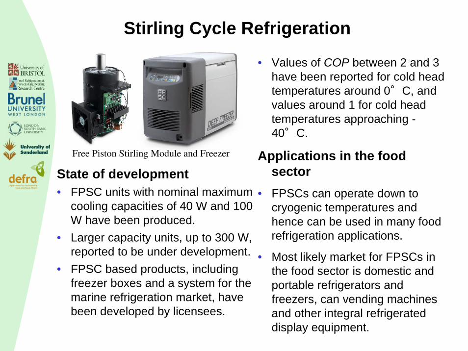
• Values of COP between 2 and 3 have been reported for cold head temperatures around 0°C, and values around 1 for cold head temperatures approaching -40°C.
Applications in the food sector
• FPSCs can operate down to cryogenic temperatures and hence can be used in many food refrigeration applications.
• Most likely market for FPSCs in the food sector is domestic and portable refrigerators and freezers, can vending machines and other integral refrigerated display equipment.
Free Piston Stirling Module and Freezer
State of development• FPSC units with nominal maximum
cooling capacities of 40 W and 100 W have been produced.
• Larger capacity units, up to 300 W, reported to be under development.
• FPSC based products, including freezer boxes and a system for the marine refrigeration market, have been developed by licensees.

Thermoelectric Refrigeration
State of development• Thermoelectric modules are
available commercially with maximum cooling capacities up to 200 W and COP around 0.6 at 0oC cooling temperature.
• Interface with heat exchange systems to facilitate heat transfer adversely influences COP.
Tc
I+
Th
n-typep-type
HeatAbsorbed
HeatRejected
?+conductor
Tc
I+
Th
n-typep-type
HeatAbsorbed
HeatRejected
+conductor
-
Tc
I+
Th
n-typep-type
HeatAbsorbed
HeatRejected
?+conductor
Tc
I+
Th
n-typep-type
HeatAbsorbed
HeatRejected
+conductor
-
Thermoelectric cooling (or Peltier) couple
Applications in the food sector• Hotel room, mobile home,
recreational vehicles and cars; portable picnic coolers; wine coolers; beverage can coolers; drinking water coolers.
• Potential applications include domestic and commercial refrigerators and freezers, and mobile refrigeration and air conditioning.

Air Cycle TechnologyApplication in the food sector• Rapid chilling and/or freezing
(including air blast, tunnel, spiral, fluidised bed and rotary tumble equipment);
• Refrigerated transport (trucks, containers, rail freight, ships)
• Integrated heating and cooling
State of development• Air is used as the working fluid. • Reasonably well established
technology.• Closed and open air cycle
systems have been developed with refrigeration capacities ranging from 11 to 700 kW.
• Current R&D on transport refrigeration (QUB) and integrated heating and cooling (Bristol funded by Defra)
QOUT
Expander Compressor
4 1
23
WIN
QIN Diagram of Air Cycle (Spence et.al., 2005)

Sorption Technologies - Adsorption
Applications in the food sector• Applications in the food sector will
be primarily in areas where waste heat is available to drive the adsorption system.
• Such applications can be found in food factories, transport refrigeration.
• Use with CHP systems for tri-generation
State of development• Already available for air
conditioning applications 35 and 1300 kW capable of being driven by low grade heat 50°C to 90 °C and able to give COPs of around 0.7. at temp. above 0oC
• R&D on development of systems for refrigeration applications.
Schematic Diagram of Adsorption chiller(Wang, 2006)

Tri-generation
Fuel
Cooling/Refrigeration
Power System
Heat Recovery
Thermally driven refrigeration
system
Electrical Power
Waste heat Heating
Figure 1. Schematic of a trigeneration system
Potential for energy and GHG emissions savings
State of development• Progress in power systems
(ICs, microturbines, fuel cells)• Heat recovery systems• Design and controls• R&D in Brunel funded by
DefraApplication in the food sector• Large food manufacturing
facilities for many years• More recently in supermarkets for
HVAC applications• Potential for the use of biofuels
(food manufacturing facilities and RDCs)
Experimental facilities at Brunel University

Current State of the Art –CO2 refrigeration systems
• Natural refrigerant• High pressures compared to
HFCs and ammonia• Potential for energy and GHG
emissions savingsState of Development• Becoming established in
Scandinavia, and Northern Europe.
• Different system arrangements –Cascade Transcritical, booster etc
Transcritical operation (Courtesy Knudsen)
CO2 pack (Courtesy Linde)

Current State of the Art –CO2 refrigeration systems
HFC/CO2 (cascade) CO2 /CO2 (cascade)
CO2 /CO2 (compound)
R717/CO2 (cascade)
Courtesy Danfoss

Current State of the Art –CO2 refrigeration systems
Application in the food sector• Supermarkets • Food processing (all types
competes with ammonia)• Transport refrigeration• Beverage coolingActivities in the UK• Limited design and
manufacturing capability in the UK for batch production (Star, Space)
• Some applications in supermarkets
• Some research and development in Universities (Brunel, London South Bank)
Integration of tri-generation and CO2 refrigeration systems (Brunel Univerity, funded by Defra)
Technology Development and Applications
Transport Refrigeration• Reduce loads (vacuum insulation)• PCM thermal storage (charge at base – RDC)• Total loss systems• Air cycle• Hybrid and solar driven systems, magnetic refrigeration • Utilise thermal energy in engine exhaust (sorption refrigeration
systems, power generation, thermoacoustic refrigeration)Supermarkets• CO2 systems (optimum configuration for UK yet to be established)• Thermal integration (heat recovery and CHP/Tri-generation)• Reduction in refrigerant charge and improvement in component
efficiencies.• Integration of renewable sources, wind, solar and ground thermal
energy (heating/cooling).
Technology Development and ApplicationsIntegral refrigeration systems (cabinets)• HC and CO2 refrigerants• Thermoelectric cooling• Stirling cycle cooling• Thermoacoustic• Magnetic refrigerationFood processing• CO2 systems and CO2 /R717 cascade systems• Air cycle technology for low temperatures and
combined heating and cooling• Thermal integration• Waste heat recovery for refrigeration (sorption
systems) and power generation (thermoelectric, Stirling, thermoacoustic, turbo-generators)
• Tri-generation (use of biofuels)

Technology Development and Applications
Food Storage (cold stores)• Biomass – sorption refrigeration systems• Biomass – tri-generation• CO2 and CO2/R717 cascade systems• Use of solar wind to generate electricity/heat to drive
vapour compression/sorption systems