new dover high school - state of delaware
TRANSCRIPT

Project Manual – Volume II
For Bid Pac G
New Dover High School Dover, Delaware
EDiS Company, Inc.
Becker Morgan Group, Inc.
ABHA Architects
Capital School District
November 9, 2012

Capital School District New Dover High School
BPG Project No. 1012
TABLE OF CONTENTS
EXECUTION AND CLOSEOUT REQUIREMENTS
01 74 19 CONSTRUCTION WASTE MANAGEMENT AND DISPOSAL…………… 5
PERFORMANCE REQUIREMENTS
01 81 13 SUSTAINABLE DESIGN REQUIREMENTS LEED FOR SCHOOLS …….. 13
01 91 13 GENERAL COMMISSIONING REQUIREMENTS ………………………… 8
01 91 14 PLUMBING COMMISSIONING REQUIREMENTS ………………………… 8
01 91 15 HVAC COMMISSIONING REQUIREMENTS ………………………………. 8
01 91 16 ELECTRICAL SYSTEMS COMMISSIONING REQUIREMENTS …………. 5
DIVISION 03 - CONCRETE
03 30 00 CAST-IN-PLACE CONCRETE……………………………………………….. 6
DIVISION 04 - MASONRY
04 20 00 UNIT MASONRY ……………………………………………………………… 8
04 72 00 CAST STONE MASONRY …………………………………………………….. 4
DIVISION 05 - METALS
05 12 00 STRUCTURAL STEEL FRAMING …………………………………………… 3
05 21 00 STEEL JOIST FRAMING ……………………………………………………… 3
05 31 00 STEEL DECKING ……………………………………………………………… 3
05 40 00 COLD-FORMED METAL FRAMING ………………………………………… 3
05 50 00 METAL FABRICATIONS ……………………………………………………... 3
DIVISION 06 - WOOD, PLASTICS, AND COMPOSITES
06 10 00 ROUGH CARPENTRY ………………………………………………………… 3
06 20 00 FINISH CARPENTRY ………………………………………………………….. 2
DIVISION 07 - THERMAL AND MOISTURE PROTECTION
07 21 00 THERMAL INSULATION …………………………………………………….. 3
07 26 40 SPRAY POLYURETHANE FOAM INSULATING AIR BARRIER………….. 7
07 26 16 UNDER-SLAB VAPOR BARRIER/RETARDER …………………………….. 2
07 42 13 METAL WALL PANELS ………………………………………………………. 3
07 53 00 ELASTOMERIC MEMBRANE ROOFING …………………………………… 5
07 62 00 SHEET METAL FLASHING AND TRIM …………………………………….. 3
07 71 00 ROOF SPECIALTIES ………………………………………………………….. 2
07 72 00 ROOF ACCESSORIES ………………………………………………………… 3
07 84 13 HVAC & PLUMBING PENETRATION FIRESTOPPING……………………. 8
07 90 05 JOINT SEALERS ……………………………………………………………….. 4

Capital School District New Dover High School
BPG Project No. 1012
DIVISION 08 - OPENINGS
08 06 71 DOORS HARDWARE SCHEDULE ………………………………………… 12
08 11 13 HOLLOW METAL DOORS AND FRAMES ………………………………… 4
08 33 23 OVERHEAD COILING DOORS………………………………………………. 7
08 33 33 COILING COUNTER DOORS ………………………………………………… 5
08 43 13 ALUMINUM-FRAMED STOREFRONTS ……………………………………. 4
08 56 55 TICKET WINDOWS …………………………………………………………… 4
08 71 00 DOOR HARDWARE …………………………………………………………. 19
08 80 00 GLAZING ………………………………………………………………………. 4
08 91 00 LOUVERS ……………………………………………………………………… 3
DIVISION 09 - FINISHES
09 05 61 COMMON WORK RESULTS FOR FLOORING PREPARATION…………... 4
09 21 16 GYPSUM BOARD ASSEMBLIES ……………………………………………. 5
09 51 00 ACOUSTICAL CEILINGS ……………………………………………………. 3
09 65 66 RESILIENT ATHLETIC FLOORING ………………………………………… 3
09 67 00 FLUID-APPLIED FLOORING ………………………………………………… 3
09 68 13 TILE CARPETING ……………………………………………………………... 3
09 90 00 PAINTING AND COATING ………………………………………………… 10
DIVISION 10 - SPECIALTIES
10 11 01 VISUAL DISPLAY BOARDS …………………………………………………. 3
10 21 13.19 SOLID COMPOSITE TOILET COMPARTMENTS ………………………….. 3
10 28 00 TOILET, BATH, AND LAUNDRY ACCESSORIES ………………………… 4
10 44 00 FIRE PROTECTION SPECIALTIES ………………………………………….. 3
10 51 00 LOCKERS ……………………………………………………………………… 5
DIVISION 11 - EQUIPMENT
11 40 00 FOODSERVICE EQUIPMENT ……………………………………………… 16
11 68 20 OUTDOOR ATHLETIC EQUIPMENT ……………………………………… 9
11 68 33 STADIUM PADDING…………………………………………………………. 3
DIVISION 12 - FURNISHINGS
12 24 13 WINDOW TREATMENT – ROLLER SHADES ……………………………… 4
12 34 00 LAMINATE CLAD CASEWORK …………………………………………….. 6
12 36 00 COUNTERTOPS AND BACKSPLASHES …………………………………… 3
12 93 00 SITE FURNISHINGS …………………………………………………………... 4
DIVISION 13 - SPECIAL CONSTRUCTION
13 34 16 GRANDSTANDS AND BLEACHERS ……………………………………… 11

Capital School District New Dover High School
BPG Project No. 1012
DIVISION 22 – PLUMBING
22 05 00 COMMON WORK RESULTS FOR PLUMBING…………………………… 20
22 05 05 PLUMBING PIPING, FITTINGS AND VALVES…………………………… 20
22 07 01 PLUMBING INSULATION…………………………………………………… 12
22 11 13 FACILITY WATER DISTRIBUTION PIPING……………………………… 13
22 13 13 FACILITY SANITARY SEWERS…………………………………………… 9
22 40 00 PLUMBING FIXTURES…………………………………………………… 16
22 40 05 PLUMBING EQUIPMENT…………………………………………………… 17
DIVISION 23 – HEATING, VENTILATING AND AIR CONDITIONING
23 05 00 COMMON WORK RESULTS FOR HVAC………………………………….. 20
23 05 05 HVAC PIPING, FITTINGS AND VALVES…………………………………. 14
23 05 48 VIBRATION CONTROLS FOR HVAC, PLUMBING AND
FIRE PROTECTION EQUIPMENT………………………………………….. 6
23 05 93 TESTING, ADJUSTING AND BALANCING FOR HVAC
AND PLUMBING…………………………………………………………….. 18
23 06 00 HEATING, VENTILATING AND AIR CONDITIONING EQUIPMENT…... 23
23 07 01 HVAC INSULATION…………………………………………………………. 13
23 09 00 AUTOMATIC TEMPERATURE CONTROL………………………………… 12
23 30 00 HVAC AIR DISTRIBUTION………………………………………………….. 15
23 81 26 VARIABLE REFRIGERANT VOLUME SPLIT SYSTEMS
WITH HEAT RECOVERY (AIR COOLED SYSTEMS)………………………10
DIVISION 26 – ELECTRICAL
26 05 00 COMMON WORK RESULTS FOR ELECTRICAL………………………….. 32
26 05 13 MEDIUM VOLTAGE CABLES………………………………………………. 6
26 05 19 LOW VOLTAGE ELECTRICAL POWER CONDUCTORS
AND CABLES………………………………………………………………….. 7
26 05 26 GROUNDING AND BONDING FOR ELECTRICAL
SYSTEMS……………………………………………………………………... 15
26 05 29 HANGERS AND SUPPORTS FOR ELECTRICAL SYSTEMS……………... 9
26 05 33 RACEWAY AND BOXES FOR ELECTRICAL SYSTEMS……………......... 16
26 09 23 LIGHTING AND BRANCH CIRCUIT CONTROL DEVICES…………......... 9
26 09 43 EXPANSION OF LUTRON QUANTUM LIGHTING CONTROLS……........ 11
26 11 18 OUTDOOR SWITCHGEAR……........................................................................ 11
26 12 00 PAD-MOUNTED TRANSFORMERS, LIQUID FILLED.................................. 5
26 22 00 LOW-VOLTAGE TRANSFORMERS................................................................. 4
26 24 16 PANELBOARDS.................................................................................................. 6
26 27 16 ELECTRICAL CABINETS AND ENCLOSURES.............................................. 3
26 27 26 WIRING DEVICES............................................................................................... 5
26 28 19 ENCLOSED SWITCHES...................................................................................... 3
26 28 23 ENCLOSED CIRCUIT BREAKERS.................................................................... 3
26 29 13 ENCLOSED CONTROLLERS............................................................................. 5
26 41 00 FACILITY LIGHTNING PROTECTION............................................................. 3
26 50 00 LIGHTING............................................................................................................. 9
26 56 00 ATHLETIC FIELD SPORTS LIGHTING........................................................... 12

Capital School District New Dover High School
BPG Project No. 1012
DIVISION 28 – ELECTRONIC SAFETY AND SECURITY
28 31 10 FIRE ALARM SYSTEM EXPANSION............................................................. 24
DIVISION 31 – EARTH WORK
31 10 00 SITE CLEARING………………………………………………………………. 4
31 20 00 EARTH MOVING…………………………………………………………… 14
31 23 19 DEWATERING………………………………………………………………. 3
31 31 16 TERMITE CONTROL…………………………………………………………. 4
31 50 00 EXCAVATION SUPPORT AND PROTECTION……………………………. 4
DIVISION 32 - EXTERIOR IMPROVEMENTS
32 12 16 ASPHALT PAVING…………………………………………………………… 8
32 13 13 CONCRETE PAVING………………………………………………………… 13
32 13 73 CONCRETE PAVING JOINT SEALANTS…………………………………… 3
32 14 00 UNIT PAVING…………………………………………………………………. 7
32 18 17 SYNTHETIC TRACK SURFACING SYSTEM……………………………….. 6
32 18 18 TENNIS COURT PAVEMENT SYSTEM……………………………………… 6
32 31 13 CHAIN LINK FENCES ………………………………………………………… 5
32 31 19 DECORATIVE FENCES AND GATES ……………………………………… 5
32 84 00 PLANT IRRIGATION………………………………………………………….. 9
32 92 00 MEADOW PLANTING ………………………………………………………… 7
32 92 23 LAWNS………………………………………………………………………….. 7
32 93 00 PLANTS…………………………………………………………………………10
DIVISION 33 - UTILITIES
33 05 00 COMMON WORK RESULTS FOR UTILITIES……………………………. 2
33 41 00 STORM UTILITY DRAINAGE PIPING…………………………………….. 10
33 46 00 SUBDRAINAGE……………………………………………………………… 5
33 71 19 ELECTRICAL UNDERGROUND DUCTS, HANDHOLES, PULLBOXES… 9
33 71 73 ELECTRICAL UTILITY SERVICES…………………………………………. 3

SECTION 12 36 00
COUNTERTOPS AND BACKSPLASHES
PART 1 GENERAL
1.01 SECTION INCLUDES
A. Refer to Scope Information Sheets for this contract bound in the Project Manual under
Section 01 10 00, Summary of Work. The Scope Information Sheets describe generally the work included in each contract, but the work is not necessarily limited to that described.
B. Countertops for manufactured casework.
C. Wall-hung counters.
1.02 RELATED REQUIREMENTS
A. Section 1140 00 - Foodservice Equipment: Stainless steel work coounters and window stools.
1.03 REFERENCE STANDARDS
A. ANSI A161.2 - Performance Standards for Fabricated High Pressure Decorative Laminate Countertops; 1998.
B. ANSI A208.1 - American National Standard for Particleboard; 2009.
C. AWI/AWMAC/WI (AWS) - Architectural Woodwork Standards; 2009.
D. NEMA LD 3 - High-Pressure Decorative Laminates; 2005.
E. PS 1 - Structural Plywood; 2007.
1.04 SUBMITTALS
A. See Section 01 30 00 - Administrative Requirements, for submittal procedures.
B. Product Data: Manufacturer's data sheets on each product to be used, including:1. Preparation instructions and recommendations.
2. Storage and handling requirements and recommendations.3. Specimen warranty.
C. Shop Drawings: Complete details of materials and installation; combine with shop drawings of cabinets and casework specified in other sections.
D. Selection Samples: For each finish product specified, color chips representing manufacturer's full range of available colors and patterns.
E. Verification Samples: For each finish product specified, minimum size 6 inches square, representing actual product, color, and patterns.
F. Test Reports: Chemical resistance testing, showing compliance with specified requirements.
G. LEED Report: Submit for wood products made from sustainably harvested wood, salvaged and reused wood, wood fabricated from recovered timber, and locally-sourced wood, as specified in Section 01 35 15.
H. Installation Instructions: Manufacturer's installation instructions and recommendations.
Capital School District
BPG
New Dover High School
Project No. 1012
COUNTERTOPS AND BACKSPLASHES BPG-11-2012
12 36 00 - 1

I. Maintenance Data: Manufacturer's instructions and recommendations for maintenance and repair of countertop surfaces.
1.05 QUALITY ASSURANCE
A. Fabricator Qualifications: Same fabricator as for cabinets on which tops are to be
installed.
B. Installer Qualifications: Fabricator.
1.06 DELIVERY, STORAGE, AND HANDLING
A. Store products in manufacturer's unopened packaging until ready for installation.
B. Store and dispose of solvent-based materials, and materials used with solvent-based
materials, in accordance with requirements of local authorities having jurisdiction.
1.07 FIELD CONDITIONS
A. Maintain environmental conditions (temperature, humidity, and ventilation) within limits recommended by manufacturer for optimum results. Do not install products under
environmental conditions outside manufacturer's absolute limits.
PART 2 PRODUCTS
2.01 COUNTERTOP ASSEMBLIES
A. Quality Standard: Premium Grade, in accordance with AWI/AWMAC/WI Architectural Woodwork Standards.
B. Plastic Laminate Countertops: High pressure decorative laminate sheet bonded to substrate.1. Laminate Sheet, Unless Otherwise Indicated: NEMA LD 3 Grade HGS, 0.048 inch
nominal thickness.a. Finish: Matte or suede, gloss rating of 5 to 20.
b. Surface Color and Pattern: As scheduled.c. Manufacturers:
1) Formica Corporation: www.formica.com.
2) Panolam Industries International, Inc\Nevamar: www.nevamar.com.3) Panolam Industries International, Inc\Pionite: www.pionitelaminates.com.4) Wilsonart International, Inc: www.wilsonart.com.
5) Substitutions: See Section 01 60 00 - Product Requirements.2. Exposed Edge Treatment: Square, substrate built up to minimum 1-1/4 inch thick;
covered with matching laminate.
3. Back and End Splashes: Same material, same construction.
2.02 ACCESSORY MATERIALS
A. Wood-Based Components:
1. Wood fabricated from old growth timber is not permitted.2. Provide sustainably harvested wood, certified or labeled as specified in Section 01
60 00.
B. Plywood for Supporting Substrate: PS 1 Exterior Grade, A-C veneer grade, minimum 5-ply; minimum 3/4 inch thick; join lengths using metal splines.
C. Particleboard for Supporting Substrate: ANSI A208.1 Grade 2-M-2, 45 pcf minimum density; minimum 3/4 inch thick; join lengths using metal splines.
D. Adhesives: Chemical resistant waterproof adhesive as recommended by manufacturer of
New Dover High School
Project No. 1012
Capital School District
BPG
12 36 00 - 2 COUNTERTOPS AND BACKSPLASHES BPG-11-2012

materials being joined.
E. Joint Sealant: Mildew-resistant silicone sealant, clear.
2.03 FABRICATION
A. Fabricate tops and splashes in the largest sections practicable, with top surface of joints flush.1. Join lengths of tops using best method recommended by manufacturer.
2. Fabricate to overhang fronts and ends of cabinets 1 inch except where top butts against cabinet or wall.
3. Prepare all cutouts accurately to size; replace tops having improperly dimensioned
or unnecessary cutouts or fixture holes.
B. Provide back/end splash wherever counter edge abuts vertical surface unless otherwise
indicated.1. Secure to countertop with concealed fasteners and with contact surfaces set in
waterproof glue.
2. Height: 4 inches, unless otherwise indicated.
PART 3 EXECUTION
3.01 INSTALLATION
A. Securely attach countertops to cabinets using concealed fasteners. Make flat surfaces level; shim where required.
B. Attach plastic laminate countertops using screws with minimum penetration into substrate board of 5/8 inch.
C. Seal joint between back/end splashes and vertical surfaces.
3.02 CLEANING
A. Clean countertops surfaces thoroughly.
3.03 PROTECTION
A. Protect installed products until completion of project.
B. Touch-up, repair or replace damaged products before Substantial Completion.
END OF SECTION
Capital School District
BPG
New Dover High School
Project No. 1012
COUNTERTOPS AND BACKSPLASHES BPG-11-2012
12 36 00 - 3

Capital School District New Dover High School BPG Project No. 1012
SITE FURNISHINGS 129300-1 BPG-11-2012
SECTION 129300 - SITE FURNISHINGS
PART 1 - GENERAL
1.1 SUMMARY
A. This section includes the following: 1. Benches 2. Picnic Tables 3. Trash and Litter Receptacles 4. Recycling Receptacles 5. Bicycle Racks 6. Flagpoles 7. Trail Bollards 8. Bollard and Chain Barriers 9. Pond Aerators 10. Floating Pond Fountains and Lights
B. Related Sections: 1. Division 3 Section “ Cast in Place Concrete” 2. Division 26 Section “Exterior Electrical”
1.2 SUBMITTALS
A. Product Data: For each type of product indicated, including assembly and installation instructions.
B. Samples for Color Verification: For units with factory-applied color finishes (bench, picnic tables, trash and recycling receptacles, bicycle racks, trail bollards and bollard and chain barrier).
C. Product Schedule: For site furnishings. Use same designations indicated on Drawings.
D. Maintenance Data: For site furnishings to include in maintenance manuals.
1.3 QUALITY ASSURANCE
A. Obtain site furnishings from specified sources.
B. Installer qualifications: 1. Site furniture to be installed by manufacturer’s Certified Installer whose work has
resulted in construction of at least five similar installations, with a record of successful in-service performance for at least three years.

Capital School District New Dover High School BPG Project No. 1012
SITE FURNISHINGS 129300-2 BPG-11-2012
1.4 DELIVERY, STORAGE AND HANDLING
A. Protect all site furniture during storage and construction against rain, snow or ground water, and against soiling or contamination from earth and other materials.
PART 2 - PRODUCTS
2.1 MATERIALS
A. Contractor to verify quantity on plans.
B. Bench: 1. Landscapeforms, Kalamazoo, MI, contact Barbara Nolan Inc, Tracey Friedly 410-951-
9090 2. Model: Scarborough 3. Backed horizontal strap with one intermediate arm rest 4. Length – 8’-0” 5. Surface mount. 6. Color: Titanium powdercoat.
C. Trash Receptacles: 1. Quantity: 24 2. Landscapeforms, Kalamazoo, MI 3. Scarborough Series, Side-opening style with vertical strap side panels 4. Surface Mount 5. Color: Titanium powdercoat.
D. Recycling Receptacles: 1. Quantity: 12 2. Landscapeforms, Kalamazoo, MI 3. Scaroborough Series, Side-opening style, single use recycling opening 4. Signage by mfr. – Type 09 (Bottles/Cans) 5. Surface Mount 6. Color: Titanium powdercoat.
E. Bicycle Rack 1. Creative Pipe Inc., 1-800-644-8467 2. Inverted ‘U’ Bike Rack 3. Model: SU-20EP, embedded mount, capacity 2 bikes. 4. Color: Metallic Silver
F. Concession Area Picnic Tables 1. DuMor Site Furnishings, 1-800-598-4018 2. Model: 156 Series PL, surface mount 3. Color: Mill Finish Aluminum

Capital School District New Dover High School BPG Project No. 1012
SITE FURNISHINGS 129300-3 BPG-11-2012
G. Flagpoles 1. Flagpole Warehouse, 1-800-962-0956 2. Architectural Series Internal Halyard flagpoles 3. Model: EC30IH, 33’-0” overall height (30’-0” exposed height) – qty.: 4 4. Model: EC40IH, 44’-” overall height (40’-0” exposed height) – qty.: 2 5. Aluminum, satin finish
H. Trail Bollards 1. Fairweather Site Furnishings, 1-800-323-1798 2. Model: B-1 Bollard, 6” dia., 42” ht., removable mounting 3. Color: Black gloss
I. Bollard and Chain Barrier 1. Fairweather Site Furnishings, 1-800-323-1798 2. Model: B-1 Bollard, 8” dia., 36” ht. with eyelets and chains. 3. Separate top for concrete fill 4. Color: Black gloss
J. Pond Aerators – Vertex Water Features, 1-800-432-4302 a. Pond #1
1) Model: Vertex High Flow Air 3 Plus for shallow water with Sound Kit for medium cabinet, (4) CoActive Air Stations
b. Pond #2 1) Model: Vertex High Flow Air 2 Plus for shallow water with Sound Kit for
medium cabinet, (2) CoActive Air Stations
K. Floating Pond Fountains – Vertex Water Features, 1-800-432-4302 a. Pond #1
1) Model: Vertex Funnel Jet Fountain (10HP/45’ dia. display) with Light Package
b. Pond #2 1) Model: Vertex Funnel Jet Fountain (2HP/25’ dia. display) with Light
Package
PART 3 - EXECUTION
3.1 INSTALLATION - GENERAL
A. Install site furnishings as per manufacturer’s recommendations and details shown in these documents. Provide electrical service where required per manufacturer’s specifications.
B. Do not install any materials with chips, cracks, discolorations and other defects that would cause visible discoloration on the finished work.
C. Stake out all locations of site furniture for approval Architect prior to installation and anchoring.

Capital School District New Dover High School BPG Project No. 1012
SITE FURNISHINGS 129300-4 BPG-11-2012
D. Site furnishings as appropriately noted shall be permanently anchored as required by the drawings and manufacturer’s recommendations.
E. Install all products plumb and level.
F. Install footings as per specifications and as required by manufacturer’s specs, structural drawings and specifications.
END OF SECTION 129300

SECTION 13 34 16
GRANDSTANDS AND BLEACHERS
PART 1 GENERAL
1.01 SECTION INCLUDES
A. Provide outdoor permanent grandstands as described and shown on drawings and
detailed in these performance specifications.
1.02 RELATED REQUIREMENTS
A. Section 03 30 00 - Cast-in-Place Concrete: Concrete Foundations.
B. Division 26 - Electrical: Main electrical feed and final hook-up to press box.
C. Division 31 - Earthwork: Surveying and site preparation.
D. Division 32 - Exterior Improvements: Landscape fabric and stone base under grandstands.
1.03 DESIGN REQUIREMENTS
A. New bleacher designs have been developed per recommendations by the district and no design changes are allowed. Contractor must verify that listed manufacturers are bidding on an equal basis as no design alterations or changes will be allowed for the bleachers or
press boxes.
B. Bleachers include:
1. Base Bid- Seats (Per Plans)a. 2,681 seats with a 42' wide steel framed sloped front two-tier press box and
permanent steel canopy cover.b. 1,353 visitor side stand with filming platform
2. Alternate Bid-
a. 3,417 seats with a 42' wide steel framed sloped front two-tier press box and permanent steel canopy cover.
b. 1,641 visitor side stand with filming platform
3. Soccer bleachers approx 817 seats4. Mitered Baseball bleachers with press box approx. 618 seats5. Mitered Softball bleachers with filming platform approx 506 seats
C. Provide necessary demolition, engineering, material, freight, concrete, installation, related site work and supervision to provide grandstand seating systems listed below in
accordance with the following performance specifications.
D. The minimum acceptable standards of design are:1. Grandstands are elevated per plans. Front Walkway to be 6'-2” deep. Center
walkway on Baseball/Softball per plans. Overall length per plans, Total net seating
capacity with Handicap seating per plans. 2. The riser height tread depth and decking type is noted on each layout.3. Aisle layout is per plans. There shall be center aisle rails or end aisle rails per code.
4. Handicap seating areas per plans with necessary closure panels.5. Finishes to be “hot dipped” galvanized on the steel understructure, clear anodized on
the seat boards, High Performance Dur-Kyn paint on the aluminum aisle nosing
strips at aisles and stairs, High Performance Dur-Kyn painted finish on aluminum stair risers and main grandstand risers. Perimeter Railing risers to be hot dipped
galvanized, rails to be clear anodized and utilizes 6 ga. black vinyl chain link fencing.
Capital School District
BPG
New Dover High School
Project No. 1012
GRANDSTANDS AND BLEACHERS BPG-11-2012
13 34 16 - 1

6. Walking Surfaces - All walking surfaces shall be manufactured and extruded in a manner that provides for spectator safety in wet conditions. Walking surface traction (slip coefficient) shall be classified as High Traction as defined by ANSI
B101.1. Surfaces shall be extruded with repetitive serrations of ridges and valleys. Walking surface shall be shop blasted to achieve the high traction certified rating. To prevent unwanted surface stains caused during the manufacturing, shipping and
installation process, surface shall have a clear anodized finished. This entire process with the anodizing must meet the walking surface traction requirements of the ANSI and ADA codes. Mill finish products are not acceptable and do not meet this
specification. Tribometer testing is no longer an approved testing method of ASTM and therefore not acceptable
7. The front and side closures where noted will be Dur-Kyn Ptd. Aluminum riser panels to provide closure from the walkway elevation to approx. 3” above grade. This closure is along the front of the bleacher and also around the front and sides of
all front exits and side ramps per plans. 8. Signage
a. Properly label all handicap seating areas
b. Provide press box signage- All press boxes- Signage to be determined9. Foundations have been designed for this project. Final approval drawings should
provide a sealed set of documents inclusive of these designs
10. Football Press Box: 42' wide steel framed, sloped front two-tier press box with exterior rear stair to filming platform and steel roof mitered canopy.
11. Baseball Press Box: steel framed sloped front design per plans.12. Seat Planks are anodized aluminum plank.13. Inspections/ Certificates - Submit with Bid:
a. AISC plant certification of manufacturer required prior to bid. Submit with bid documents.
b. National floor safety institute or approved equal documentation for extra traffic
coating as specified meeting high traction per ANSI B101.1c. Press boxes shall include ICC certified inspections for construction of electrical
work. Data plate, certified sticker and back up documentation required.
1.04 QUALITY ASSURANCE
A. Manufacturers Qualifications: 1. Manufacturers must have a minimum of ten years of experience in the
manufacturing of grandstands and press boxes under current company name as a
sole source provider. 2. Manufacturer must provide five references (if requested) of similar projects within a
reasonable driving distance from the project site completed in the last three years for visual inspection. References shall include scope of work, contract amount, owner's name and phone numbers, contract completion date and actual completion date.
3. Manufacturer shall have local representation within a reasonable mile radius of the project. Representative is responsible to attend job site meetings, provide sequencing and scheduling information and make decisions on behalf of the
manufacturer. Due to the coordination and timeframe of this project, it is imperative that this representative can immediately respond, in person, to evaluate questions, concerns and actions and resolve issues that immediately impact the
fabrication and installation of the product or other contractors' abilities to proceed with their work. Resume of representatives needs to be submitted for review and
approval. 4. List with submission the date that you visited the site and reviewed the existing
conditions.
New Dover High School
Project No. 1012
Capital School District
BPG
13 34 16 - 2 GRANDSTANDS AND BLEACHERS BPG-11-2012

5. If approved bidder is a dealer or representative of the manufacturer in addition to the manufacturer the dealer must provide the same information required in this section.
6. Welders must be AWS certified; manufacturing capabilities in accordance with the
governmental agencies having jurisdiction.
B. Installers Qualifications:
1. Factory-trained and experienced in the installation of grandstands.2. Project is a prevailing wage job. Certified payrolls are required on this project.
C. Source Quality Control: Mill Test Certification.
D. Single Source Responsibility: Obtain all of each distinct material required from a single
manufacturer.
E. Code Compliance: Provide aluminum bleachers to meet or exceed all State and Local
applicable codes and in compliance with the IBC/ICC National Code and CABO/ANSI A117.1 Barrier Free Subcode, Current Editions.
1.05 SUBMITTALS
A. Product Data: Submit technical data for each distinct type of material, component and
accessory indicated. 1. Include information which specifically details physical properties and performance
characteristics.
B. Shop Drawings: Manufacturer to submit shop drawings and structural design
calculations signed and sealed by a Delaware licensed Professional engineer, and schedules for type, location, quantity and details of all aluminum components required for this project.
1. Indicate on shop drawings that products are in compliance with IBC/ICC National Building Code and all other State and Local Codes and Regulations.
2. Concrete designed per American Concrete Institute Guidelines
C. Samples: Submit manufacturer's samples for aluminum components, and an 18 inch seat sample.
D. Certificate: Submit manufacturer's certification that materials furnished comply with requirements indicated and also in compliance with the IBC/ICC code and all other
applicable Federal, State and local codes, and that materials meet or exceed test requirements indicated.
1.06 WARRANTY
A. Submit a written warranty signed by the manufacturer, installer, and the contractor, guaranteeing to correct failures for a period of two (2) years after substantial completion, without reducing or otherwise limiting any other rights to correction which owner may
have under the contract documents. Failures are defined to include faulty workmanship or faulty materials. Correction may include repair or replacement.
1.07 BUILDING CODES
A. Comply with all applicable codes, which include but are not limited to the following:
1. IBC/ICC Building Code- Current Edition2. AISC Manual of Steel Construction, 9th Edition3. Aluminum Association of America Guidelines
4. IBC barrier free sub-code and Guidelines5. U.S. Department of Justice ADA Standards
6. American Concrete Institute
Capital School District
BPG
New Dover High School
Project No. 1012
GRANDSTANDS AND BLEACHERS BPG-11-2012
13 34 16 - 3

B. The bleacher shall be designed to support, in addition to its own weight, a uniformly distributed live load of not less than 100 pounds per square foot of gross horizontal projection of the bleacher.
1. Add 6 pounds per square foot of dead load on seats, footboards, risers and steel framing.
C. All seat and footboard members shall be designed to support not less than 120 pounds per linear foot. The bleacher shall be designed to resist, with or without live load, horizontal wind load appropriate for local conditions. It shall also be designed to resist, in
addition to the live load, sway forces applied to the seats in a direction parallel to the length of the seat planks 24 pounds per liner foot; and, in a direction perpendicular, stresses in aluminum members and connections shall not exceed those specified for
Building Type Structures by the Aluminum Association.
D. General: The structure shall be properly braced for wind and construction loads until all structural elements are secured. Lateral and longitudinal bays shall be cross-braced as required. Guardrails shall be of adequate size, location, and height to meet specified
codes and designed to carry required loads. Exit stairs and intermediate aisle stairs shall be completely closed, in the direction of travel and shall have a maximum rise of 7 inches and a minimum tread of 11 inches.
E. Code Compliance: Submittals shall be based upon specifications and drawings contained in the bid documents. Architect will not review any design or product changes prior to
the bid date. Design changes to reduce overall aisle egress calculations or number of stair and ramp exits will not be allowed. Design changes to seatboard bracket support and location is not allowed. All bidders must bid in accordance with these specifications.
1. The Bleacher Contractor shall be responsible to meet the code interpretation provided in the bid documents and modify as required by state or local
governmental review boards.2. Calculations that demonstrate code compliance with egress and exit of aisles, stairs,
and ramps are a required submission with approved drawings.
PART 2 - PRODUCTS
2.01 MANUFACTURERS
A. Basis of Design:
1. Southern Bleacher Company, 801 Fifth St., P.O. Box One, Graham, Texas 76450, (800) 433-0912.
B. Products specified herein have been selected because of their quality of construction, configuration, design, function, available finishes, components, accessories, dimensions, shape and style.
C. Other manufacturers include:1. Dant Clayton Corporation, 1500 Bernheim Lane, Louisville, KY 40210 (502)
634-3626.2. Outdoor Aluminum Inc., P.O. Box 118, Geneva, AL 36340, (800) 225-4249.
D. All manufacturers shall submit the following information to verify compliance and financial responsiblity for meeting the intent of these performance specifications.
1. Provide a side by side comparison of all products specified including the press box per these performance specifications
2. Provide documentation certifying that the all walking surfaces meet the criteria set
forth in the specifications3. Provide proof of a minimum of 10 years manufacturing experience.
New Dover High School
Project No. 1012
Capital School District
BPG
13 34 16 - 4 GRANDSTANDS AND BLEACHERS BPG-11-2012
4. Provide a reference list with contacts for a minimum of 5 projects within a reasonable driving distance from the project site over the last 3 years. This list should be of similar projects.
5. Provide a sample drawing of press box to verify compliance with specified box.6. Provide proof of participation and certification listed in 1.1.13
E. Sole source manufacturing: All products within this specification shall be manufactured by a sole source facility.
F. Architect/Engineer/Owner reserves the right to accept or reject Grandstand manufacturers. All approvals will be in writing through addendum prior to the bid date.
2.02 PERMANENT STEEL GRANDSTAND
A. Interlocking Deck- Home and Visitor Football Grandstands; Semi-Closed Aluminum
Decking for Soccer Stand and Fully Closed Tongue and Groove Decking for Baseball and Softball Grandstands.
B. All as shown and noted on plans.1. The intent of the product design is to reduce deflection of aluminum deck and to
eliminate fluid drainage below spectator seating. 2. All individual deck members shall be locked together longitudinally at all treads,
front walk and cross walk locations.
3. This design, in ambient conditions, allows for expansion and contraction without damage or deformation of the aluminum deck.
4. The locking design does not allow any fluids to pass to the ground under the
spectator seating. 5. Extrusion gutters are part of each decking member that will allow for the collection
and control of fluids that occur on the deck surface.
6. At all butt joint locations, internal gutters shall be mounted onto the structural members to direct fluids to determined locations.
7. Vertical columns are to be placed 6 feet 0 inches on center laterally and front to back per plans.
8. Traverse bays are free of cross bracing the total length of the grandstand.
9. Stringers are wide flange with steel angle rise and depth fabrication and are placed 6 feet on center.
C. Front Walkway:1. All grandstands to be elevated per plans.
D. Entry stairs: 1. Firmly anchored to uniformly poured concrete bases. 2. Stair rise: 7 inches max. per IBC Building Code with aluminum closure.
3. Stair tread depth: 11 inches min. per IBC Building Code.4. Guardrails on Stair to be 42 inches above leading edge of step with intermediate
rails.
5. Stairs to have handrail extension. The handgrip portion of handrails shall not be less than 1 1/2 inches or more than 2 inches in cross-sectional dimension or the shape
shall provide an equivalent gripping surface. The handgrip portion of handrails shall have a smooth surface with no sharp corner. The top of handrails and handrail extensions shall be placed not less than 34 inches or more than 38 inches above the
nosing of treads and landings. Handrails shall be continuous the full length of the stairs and shall extend in the direction of the stair run not less than 12 inches beyond the bottom riser. Ends shall be returned or shall terminate in newel posts or safety
terminals.
Capital School District
BPG
New Dover High School
Project No. 1012
GRANDSTANDS AND BLEACHERS BPG-11-2012
13 34 16 - 5
E. Aisles:1. Aisles with seating on both sides to have 34-inch high handrail with intermediate
rail at approximately 22 inches above tread.
2. Anodized aluminum handrails with rounded ends (no fittings) are discontinuous to allow access to seating through a space 22 inches (min.) to 36 inches (max.).
3. Intermediate steps shall provide equal rise and run throughout aisle. Each shall have
aisle nosing with Dur-Kyn finish and riser closure with Dur-Kyn finish.
F. Interlock Deck System-
1. Rise and depth at each row is per plans2. Each seat 17 inches above its respective tread.3. Decking Arrangement:
a. The seats shall be 2”x10” seat plank with two internal legs and extruded aluminum alloy, 6063-T6 with clear anodized 204R1, AA-M10C22A31, Class
II finish. Mounting brackets to be “L” type riser mounted.b. The tread system shall be comprised of uniform serrated, slip resistant
aluminum extrusions which interlock together lengthwise and form a .922” x
.60” V-shaped gutter running the length of the planks. The interlocking mechanism will minimize deflection and not separate due to loads being applied to individual planks. The locking mechanism by design shall allow for
expansion and contraction of individual planks without effecting performance of the system.
c. The system shall cause the deck planks to react together at all treads and cross
walks to live load and form the appearance of a single tread system. By design, this system forms a solid, overlapping tread and riser installation.
d. The nose extrusion shall allow for a 1” extruded aluminum contrasting nose piece to be flush mounted on the leading edge and shall capture the vertical riser plank in an extruded pocket. The heel extrusion shall have a .70” vertical
lip at the rear of the plank to allow for placement of vertical riser plank and inhibit fluids from escaping at the rear of the tread.
e. These extrusions shall be such that the attachment of the seat brackets, step
brackets, mid-aisle rails and all other components is accomplished without deck penetrations. No through-bolting or drilling of the aluminum tread / riser system shall be permitted.
f. The system shall allow for seat and aisle reconfiguration at any time without evidence of its previous configuration.
g. At all butt joint locations of the interlocking deck system, a secondary gutter shall be installed below the aluminum tread / riser system that allows fluids to be contained and gravity flow toward the first tread. This gutter will collect
fluids and control them to specific areas.h. The secondary gutter system shall be placed on to the structural steel support
system of the grandstand such that the gutter is supported by stringers (raker
beams) at each side. These stringers (raker beams) shall be a minimum 12” apart to allow for adequate gutter widths to properly collect fluids drainage.
i. These secondary gutters shall terminate at strategic locations dependent on the
grandstand layout. At the termination points, a collection box will be provided such that the owner can make a connection to allow for desired fluid routing.
The intention is to control a majority of the water from collection at the front or under the stand.
j. Entry stairs and ramps to be 2 x 12 mill finish aluminum.
k. Open ends of planks to be covered with aluminum end caps, securely fastened to the plank.
New Dover High School
Project No. 1012
Capital School District
BPG
13 34 16 - 6 GRANDSTANDS AND BLEACHERS BPG-11-2012

l. Joint sleeves: Dual joint sleeves to be inserted at each butt joint of each load bearing aluminum plank, and to penetrate 6 inches into each plank at the joint. Joint sleeves are not required at secondary gutter locations.
G. Guardrailing: 1. To be at sides and front of bleacher. Also provide railing along front and sides of
accessible areas per plans. 2. Railing to be anodized aluminum with end plugs at ends of straight runs and/or
elbows at corner.
3. All guardrails shall be secured to angle rail risers by galvanized fasteners. 4. Railing shall be 42" above walkways and entrances. 5. Railing shall be 42" above any adjacent seat.
6. Guardrailing on sides, front and rear of stand to be 6 ga. black vinyl fence fabric closure design per plans and details providing a separate top rail.
H. Ramps:1. Slope: maximum 1:12 using aluminum tongue and groove deck planks
2. Guardrail to be 42 inches above ramp with black vinyl coated chain link rail system and 2 x 6 toeboard.
3. Handrail: Ramps to have handrail extension. The handgrip portion of handrails
shall not be less than 1 1/2 inches or more than 2 inches in cross-sectional dimension or the shape shall provide an equivalent gripping surface. The handgrip portion of handrails shall have a smooth surface with no sharp corners. The top of handrails
and handrail extensions shall be placed not less than 34 inches or more than 38 inches above the ramp surface. Handrails shall be continuous the full length of the ramp and shall extend in the direction of the ramp not less than 12 inches beyond
the end of the ramp. Ends shall be returned or shall terminate in newel posts or safety terminals.
4. All ramp footboards will run perpendicular to the direction of travel, to ensure proper function of anti-skid flutes. Running plank parallel is strictly prohibited.
I. Handicap provision:1. Quantity of wheelchair spaces: Per Plans.2. Sides and front of accessible forward pockets to be closed. Sides to have galvanized
steel plate factory applied and front closure to be a series of Kynar painted riserboards. Adequate to provide complete closure.
3. Floor mounted companion benches to be provided where necessary
J. Materials/Finishes1. Substructures:
a. Structural shapes meet one of the following ASTM specifications: A36, A36/A572 grade 50, A572, grade 50, A529-50, or A500 grade B.
b. Shop connections are seal welds.c. After fabrication, all steel is hot-dipped galvanized to ASTM-A-123
specifications.
2. Extruded Aluminum: a. Seat Planks and Railing are extruded aluminum alloy, 6063-T6 with clear
anodized 204R1 coating.
b. Riser board planks and closure planks are extruded aluminum alloy, 6063-T6, Dur-Kyn painted finish.
c. Tread planks are extruded aluminum alloy 6063-T6 mill finish
Capital School District
BPG
New Dover High School
Project No. 1012
GRANDSTANDS AND BLEACHERS BPG-11-2012
13 34 16 - 7

d. Joint Sleeve Assembly to be inserted in flat plank to maintain true alignment in joining together two plank pieces. Extruded aluminum alloy, 6063-T, mill finish. Splice cover is unacceptable between two flat plank pieces joined in a
straight line.
K. Accessories:
1. Channel End Caps: Aluminum alloy 6063-T6, clear anodized 204R1, AA-M10C22A31, Class II.
2. Hardware:
a. Bolts, Nuts: Hot-dipped galvanized or mechanically galvanized.b. Hold-down Clip Assembly: Aluminum alloy 6005A-T6, mill finish.c. Structural Hardware: Equal to or greater than hot-dipped galvanized
ASTM-A307. No connections utilizing high strength bolts are classed as slip critical.
3. Aisle Nose and Stair Nose: Aluminum alloy, 6063-T6, non-skid painted finish. This extrusion shall be recessed into the front floor nosing plank in order to prevent a tripping hazard, no surface mounting will be acceptable.
L. Fabrication:1. Design Load:
a. Live Load: 100 psf gross horizontal projection.b. Lateral Sway Load: 24 plf seat plank.c. Perpendicular Sway Load: 10 plf seat plank.
d. Live Load of Seat and Tread Planks: 120 plf.e. Guardrail: Per IBC/ICC Building Code.f. Windload: 30 psf.
2. All manufactured connections to be shop welded.a. Manufactured by certified welders conforming to AWS Standards.
2.03 TWO-TIER PRESS BOX WITH STEEL FRAME STRUCTURE
A. Product Description: 1. Type II Construction Design; sloped front design with end viewing glass per plans.
a. Press Box Dimensions: Base Bid- Two-tier 10'-6" Base, 12'-0" overall depth x
42'-0" long, plus landings for football, with permanent steel framed canopy cover per plans.
b. Press box Dimensions- Baseball - 8'-0" wide x 18'-0" long, plus landings.
2. Press Box to be of open construction, allowing inspection of electrical wiring, switches and other components without destructive disassembly.
3. Pressbox to be constructed with rear exterior stair to filming platform where shown.
B. Materials/Finishes1. Press Box Support Structure:
a. Structural shapes meet one of the following ASTM specifications: A36, A36/A572 grade 50, A572 grade 50, A529-50, or A500 grade B.
b. Shop connections are seal welds.c. After fabrication, all steel is hot-dipped galvanized to ASTM-A-123
specifications.
2. Press Box: All materials shall be new and shall comply with ASTM specifications. a. Floor
1) Main support to be a galvanized steel floor frame sized to support structure
and metal belly pan for support of insulation.2) Floor to be INTERLOCK Aluminum Decking System, extruded aluminum
alloy 6063-T6. Attach Decking System to steel floor frame with
New Dover High School
Project No. 1012
Capital School District
BPG
13 34 16 - 8 GRANDSTANDS AND BLEACHERS BPG-11-2012

mechanical fasteners at end of plank and at intermediate supports.3) Walking surface traction (slip coefficient) shall be classified as "High
Traction" as defined by ANSI B101.1 to match grandstand walkway finish.
4) Insulation: Kraft faced fiberglass building insulation R-11, 3 1/2 inches thick. Batt or roll as manufactured by Owens-Corning Fiberglass Corp., or equal.
b. Wall Structure Steel Framing 1) 4 inch x 4 inch x 11 gauge square tubing with maximum span of 14 feet on
front wall and maximum span of 6 feet on back wall and 4 inch x 2 1/2
inch x 14 gauge steel "cees" with maximum spacing of 5 feet for all walls with siding. Spans greater than these require engineered calculations for
design. 2) Insulation: Kraft faced fiberglass building insulation R-11, 3 ½ inches
thick. Batt or roll as manufactured by Owens-Corning Fiberglass Corp.,
or equal.3) Interior Finish
(a) 1/2 inch vinyl coated gypsum panels, Gold Bond vinyl-surfaced
Durasan- Santa Fe porcelain.(1) Cove Base: Vinyl 4 inches x .080 color to be medium gray.
4) Exterior Finish
(a) 26 gauge prefinished R-Panel paneling as manufactured by MBCI, Signature 200 color series, color to be determined.
(b) Wall panels are attached with #12 TEK screws - 6” O.C. at the top and bottom of the panels. Lap screws are placed at each end of the panels, at the intermediate supports, and at the mid point between
supports (TEK #14). All fasteners to be painted same color as exterior paneling.
c. Roof Structure
1) 4 inch x 4 inch x 11 gauge square tubing with maximum spacing of 6 feet on center and 4 inches x 2 1/2 inches x 14 gauge steel "cees" with maximum spacing of 2 feet on center.
2) Roof: 1/8 inch fourway steel plate roof, continuous welded seams coated with acrylic metal primer as manufactured by Coronado and 36 mils of acrylink roof coating as manufactured by Isothermal Protective Coatings,
or equal. Plate is welded on both sides of rafters with 1-1/2 inch long 1/8 inch fillet welds on 12 inch centers.
3) Insulation: Kraft faced fiberglass building insulation, R-19 (minimum) 6 inches thick. Batt or roll as manufactured by Owens-Corning Fiberglas Corp., or equal.
4) Cornice: 26 gauge steel prefinished- color to be determined.5) Ceiling: 24 inch x 24 inch x 5/8 inch acoustical ceiling tile architectural
revealed edge style wind clips and other components as manufactured by
USG, or equal.6) Roof to have a steel framed canopy cover at football press box only.
d. Exterior Doors
1) Full flush steel construction with honeycomb core. 18 gauge skin sheets. Dimensions: 3 feet 0 inches x 6 feet 8 inches. Color: White.
2) Steel door frame (16 gauge) complete with 1/2 inch threshold and weather-stripping.
3) Exterior Hardware: Yale 546F Exterior Trim, or equal. Handles shall be
lever type that allows operation without tight grasping or twisting of the wrist. All exterior hardware must accommodate District standard Best core keyed lock system.
Capital School District
BPG
New Dover High School
Project No. 1012
GRANDSTANDS AND BLEACHERS BPG-11-2012
13 34 16 - 9

4) Interior Hardware: Yale 2100 Exit Device, or equal. Handle shall be panic bar that allows for opening without any grasping, twisting or turning.
e. Interior Walls
1) Framing to be steel galvanized studs (25 gauge) 1 1/4 inch x 3 5/8 inch at maximum 2 feet on center.
2) Finishes to be consistent with all other interior finishes.
f. Windows 1) Provide 24” x 56” interior window in each wall.2) Frame: Extruded aluminum single hung, vertical sliding unit, thermal
break.3) Sash: Tilt toward inside for easy cleaning.
4) Glazing: Clear tempered panes.5) Dimensions of each unit: Dependent on compartment size. At interior
wall locations or structural support locations the dimension between
windows shall be no greater than 6 inches.6) Finish: Electrostatically applied acrylic enamel.
g. Work Bench
1) 18 inch deep clear anodized aluminum countertop with a radius front edge.2) Support using 4” x 2” x 14 ga. Steel “cee” on 4” x 4” x 11 ga. Sq. tubing
welded to steel.
h. Painting: Materials equal to. Coronado or equal.1) Surfaces: Exterior Door(s), Door Frame(s)
(a) Primer: Applied by Door Manufacturer.(b) Finish: 2 coats acrylic latex semi-gloss enamel applied by press box
manufacturer.
2) Surfaces, Exterior Siding(a) Primer: Applied by Siding Manufacturer.(b) Finish: Applied by Siding Manufacturer.
(c) Touchup: If applicable3) Surfaces: Wall and Roof Structure
(a) Primer: Coronado DTM Industrial 180-11 acrylic metal primer
applied after welding, or equal.i. Caulking: Sonneborn NP1 - Polyurethane sealant, All temperature, UV
resistant, or equal.
j. Electrical Work: 1) Submittal drawing shall indicate devices and circuitry.
2) Fixtures: Recessed 2'x4' static T8 Troffer fluorescent light fixture for use in grid ceiling systems.
3) Wiring to be in nonmetallic Panduit, or equal. N.E.C. breaker box to be
100 amp service mounted on wall with 2 inch rigid conduit to be stubbed out at back wall of press box ready for service line to be connected.
4) Service line to Press Box
5) Electrical outlet(s) installed per NEC shall be standard duty. 6) Sound, Telephone, Clock, Field Communication: Empty double outlet
boxes per N.E.C. with 3/4 inch conduit stubbed out bottom of Press Box
for use of Owner. 7) Outlet boxes to be flush mounted into wall. Any wiring completed on-site
will be responsibility of such contractor for inspections. Quantity per plans. 8) Filming Area/Observation Deck: Weathertight outlet box for cameras.
Quantity: Two. Owner shall indicate additional outlets needed.
9) Provide Electric Baseboard heat in each room. Quantity per plans.
New Dover High School
Project No. 1012
Capital School District
BPG
13 34 16 - 10 GRANDSTANDS AND BLEACHERS BPG-11-2012

10) Provide in each of the four rooms an emergency combination exit/flood light with battery back-up. Also provide two exterior emergency lights with remote heads.
11) Provide (2) wall mount exterior lights with photocell12) Provide fire extinguishers rated for proper use alongside each exit door.
3. Filming Area/Observation Deck
a. Access1) Exterior rear stair entrance (Football)2) Roof hatch (Baseball)
b. Roof guardrailing: 42” above walking surface around perimeter of deck attached to 5/8 inch galvanized studs welded to roof support structure.
1) Guardrailing: black vinyl coated 6 gauge fencing.c. Steel framed canopy cover at football press box per plans.
PART 3 - EXECUTION
3.01 INSTALLATION
A. All work performed by technicians experienced in bleacher seating. Project references may be required to verify the quality of finished projects.
1. Installation with proven experience in the Mid-Atlantic region. Requirement for a minimum of (3) installer references in DE for this project of similar size and scope.
B. Project is only to be installed as per approved shop drawings.
3.02 FIELD QUALITY CONTROL
A. Foundation: Footings for the grandstand shall provide sufficient bearing area at bottom to support all loads of the grandstand. Depth and design of footings have been designed
for this project and shall be bid in accordance with the plans and specifications. Hot-dipped galvanized anchor bolts shall be secured in the concrete footings. 1. Concrete shall attain working strength of 3,500 psi.
3.03 CLEAN-UP
A. Clean up all debris caused by work of this section removed from site.
B. Upon completion of the work and final inspections, bleacher manufacturer shall broom
clean the stand removing all loose debris.
C. If broom cleaning does not properly remove dirt and debris from the surface, pressure washing will be required.
END OF SECTION
Capital School District
BPG
New Dover High School
Project No. 1012
GRANDSTANDS AND BLEACHERS BPG-11-2012
13 34 16 - 11


Capital School District New Dover High School BPG Project No. 1012
COMMON WORK RESULTS FOR PLUMBING 22 05 00-2 BPG-11-2012
SECTION 22 05 00
COMMON WORK RESULTS FOR PLUMBING PART 1. GENERAL 1.01. SUMMARY
A. All work under Division 22 is subject to the Division 01, General Requirements, the General Conditions and Supplementary Conditions.
B. Provide all labor, materials, equipment, and services necessary for and incidental to the
complete installation and operation of all plumbing work.
C. Unless otherwise specified, all submissions shall be made to, and acceptances and approvals made by the Architect and the Engineer.
D. Contract Drawings are generally diagrammatic and all offsets, fittings, transitions and
accessories are not necessarily shown. Furnish and install all such items as may be required to fit the work to the conditions encountered. Arrange piping, equipment, and other work generally as shown on the contract drawings, providing proper clearance and access. Where departures are proposed because of field conditions or other causes, prepare and submit detailed shop drawings for approval in accordance with Submittals specified below. The right is reserved to make reasonable changes in location of equipment, piping, up to the time of rough-in or fabrication.
E. Conform to the requirements of all rules, regulations and codes of local, state and federal
authorities having jurisdiction.
F. Coordinate the work under Division 22 with the work of all other construction trades.
G. Be responsible for all construction means, methods, techniques, procedures, and phasing sequences used in the work. Furnish all tools, equipment and materials necessary to properly perform the work in first class, substantial, and workmanlike manner, in accordance with the full intent and meaning of the contract documents.
1.02. PERMITS AND FEES
A. Obtain all permits and pay taxes, fees and other costs in connection with the work. File necessary plans, prepare documents, give proper notices and obtain necessary approvals. Deliver inspection and approval certificates to Owner prior to final acceptance of the work.
B. Permits and fees shall comply with the Division 01, General Requirements of the
specification. 1.03. EXAMINATION OF SITE
A. Examine the site, determine all conditions and circumstances under which the work must be done, and make all necessary allowances for same. No additional cost to the Owner will be permitted for contractors failure to do so.

Capital School District New Dover High School BPG Project No. 1012
COMMON WORK RESULTS FOR PLUMBING 22 05 00-3 BPG-11-2012
B. Examine and verify specific conditions described in individual specifications sections.
C. Verify that utility services are available, of the correct characteristics, and in the correct
locations. 1.04. CONTRACTOR QUALIFICATION
A. Any Contractor or Subcontractor performing work under Division 22 shall be fully qualified and acceptable to the Architect and Owner. Submit the following evidence when requested:
1. A list of not less than five comparable projects which the Contractor completed.
2. Letter of reference from not less than three registered professional engineers,
general contractors or building owners.
3. Local and/or State License, where required.
4. Membership in trade or professional organizations where required.
B. A Contractor is any individual, partnership, or corporation, performing work by contract or subcontract on this project.
C. Acceptance of a Contractor or Subcontractor will not relieve the Contractor or
subcontractor of any contractual requirements or his responsibility to supervise and coordinate the work, of various trades.
1.05. MATERIALS AND EQUIPMENT
A. Materials and equipment installed as a permanent part of the project shall be new, unless otherwise indicated or specified, and of the specified type and quality.
B. Where material or equipment is identified by proprietary name, model number and/or manufacturer, furnish named item, or its equal, subject to approval by Engineer. Substituted items shall be equal or better in quality and performance and must be suitable for available space, required arrangement, and application. Submit all data necessary to determine suitability of substituted items, for approval.
C. The suitability of named item only has been verified. Where more than one item is
named, only the first named item has been verified as suitable. Substituted items, including items other than first named shall be equal or better in quality and performance to that of specified items, and must be suitable for available space, required arrangement and application. Contractor, by providing other than the first named manufacturer, assumes responsibility for all necessary adjustments and modifications necessary for a satisfactory installation. Adjustments and modifications shall include but not be limited to electrical, structural, support, and architectural work.
D. Substitution will not be permitted for specified items of material or equipment where
noted.

Capital School District New Dover High School BPG Project No. 1012
COMMON WORK RESULTS FOR PLUMBING 22 05 00-4 BPG-11-2012
E. All items of equipment furnished shall have a service record of at least five (5) years. 1.06. FIRE SAFE MATERIALS
A. Unless otherwise indicated, materials and equipment shall conform to UL, NFPA and ASTM standards for fire safety with smoke and fire hazard rating not exceeding flame spread of 25 and smoke developed of 50.
1.07. REFERENCED STANDARDS, CODES AND SPECIFICATIONS
A. Specifications, Codes and Standards listed below are included as part of this specification, latest edition.
B. ASHRAE - American Society of Heating, Refrigerating and Air Conditioning Engineers
C. ASME - American Society of Mechanical Engineers D. ASPE - American Society of Plumbing Engineers E. ASTM - American Society for Testing and Materials F. AWWA - American Water Works Association G. DNREC - Delaware Department of Natural Resources and
Environmental Control H. IBC - International Building Code I. IEEE - Institute of Electrical and Electronics Engineers J. MSSP - Manufacturers Standards Society of the Valve and Fittings
Industry K. NEC - National Electrical Code L. NEMA - National Electrical Manufacturers Association M. NSF - National Sanitation Foundation N. UL - Underwriters' Laboratories
O. All plumbing equipment and materials shall comply with the codes and standards listed
in the latest edition of ASHRAE HVAC Applications Handbook, Chapter entitled Codes and Standards.
1.08. SUBMITTALS, REVIEW AND ACCEPTANCE
A. Equipment, materials, installation, workmanship and arrangement of work are subject to review and acceptance. No substitution will be permitted after acceptance of equipment or materials except where such substitution is considered by the Architect to be in best interest of Owner.
B. LEED Submittal:
1. Product Data for Credit MR 4.1 (and Credit MR4.2): For products having recycled content, required documentation for LEED submittal indicating percentages by weight of postconsumer and pre-consumer recycled content. Include statement indicating costs for each product having recycled content. See Division 01 Sections related to LEED.
2. Product Data for Credit MR 5.1 (and MR 5.2): For product manufactured, assembled, or extracted within 500 miles of project site, documentation as required for LEED submittal. Include statement indicating costs for each product

Capital School District New Dover High School BPG Project No. 1012
COMMON WORK RESULTS FOR PLUMBING 22 05 00-5 BPG-11-2012
that is regional. See Division 01 Sections related to LEED. 1.09. SHOP DRAWINGS
A. Prepare and submit shop drawings for all plumbing equipment, specially fabricated items, modifications to standard items, specially designed systems where detailed design is not shown on the contract drawings, or where the proposed installation differs from that shown on contract drawings.
B. Submit data and shop drawings including but not limited to the list below, in addition to
provisions of the paragraph above. Identify all shop drawings by the name of the item and system and the applicable specification paragraph number and drawing number.
C. Every submittal including, but not limited to the list below, shall be forwarded with its
own transmittal as a separate, distinct shop drawing. Grouping of items/systems that are not related shall be unacceptable.
D. Items and Systems
Access Doors/Panels including layout and location Automatic Temperature Control System and Equipment as it relates to plumbing system Backflow Preventers Coordinated Drawings Direct Buried Piping Domestic Water Expansion Tanks Domestic Water Heaters Drip Pans Fire Stopping - Methods and Materials Floor and Roof Drains Hose Bibbs and Wall Hydrants Identification System In-Line Circulators Material and Equipment List Operations and Maintenance Manuals Pipe Materials Including Itemized Schedule Plumbing Fixtures & Trim Preliminary Testing and Balancing Report Pressure Relief Valves Roof Drains Schrader Fitting Valves Test Certificates Thermal Insulation Materials Include Table Summary Thermometers and Gauges Thermostatic Mixing Valves Trap Priming Station Valves Water Meters Wiring Diagrams, Flow Diagrams and Operating Instructions
E. Contractor, additionally, shall submit for review any other shop drawings as required by
the Architect. No item shall be delivered to the site, or installed, until the Contractor has

Capital School District New Dover High School BPG Project No. 1012
COMMON WORK RESULTS FOR PLUMBING 22 05 00-6 BPG-11-2012
received a submittal from the Engineer marked Reviewed or Comments Noted. After the proposed materials have been reviewed, no substitution will be permitted except where approved by the Architect.
1.10. CUTTING AND PATCHING
A. Accomplish all cutting and patching necessary for the installation of work under Division 22. Damage resulting from this work to other work already in place, shall be repaired at Contractor's expense. Where cutting is required, perform work in neat and workmanlike manner. Restore disturbed work to match and blend with existing construction and finish, using materials compatible with the original. Use mechanics skilled in the particular trades required.
B. Do not cut structural members without approval from the Architect or Engineer.
1.11. PENETRATION OF WATERPROOF CONSTRUCTION
A. Coordinate the work to minimize penetration of waterproof construction, including roofs, exterior walls, and interior waterproof construction. Where such penetrations are necessary, furnish and install all necessary curbs, sleeves, flashings, fittings and caulking to make penetrations absolutely watertight.
B. Where plumbing vents or other pipes penetrate roofs, flash pipe with Stoneman Stormtite,
Pate or approved equal, roof flashing assemblies with skirt and caulked counter flashing sleeve.
C. Furnish and install pitch pockets or weather tight curb assemblies where required.
D. Furnish and install roof drains, curbs, and vent assemblies specifically designed for application to the particular roof construction, and install in accordance with the manufacturer's instructions. The Contractor shall be responsible for sleeve sizes and locations. All roof penetrations shall be installed in accordance with manufacturer’s instructions, the National Roofing Contractors Association, SMACNA, and as required by other divisions of these specifications.
1.12. CONCRETE AND MASONRY WORK
A. Furnish and install concrete and masonry work for equipment foundations, supports, pads, and other items required under Division 22. Perform work in accordance with requirements of other applicable Divisions of these specifications.
B. Concrete shall test not less than 3,000 psi compressive strength after 28 days.
C. Grout shall be non-shrink, high strength mortar, free of iron of chlorides and suitable for
use in contact with all metals, without caps or other protective finishes. Apply in accordance with manufacturer's instructions and standard grouting practices.
1.13. EXCAVATION AND BACKFILLING
A. GENERAL

Capital School District New Dover High School BPG Project No. 1012
COMMON WORK RESULTS FOR PLUMBING 22 05 00-7 BPG-11-2012
1. Perform all necessary excavation, or installation of work under Division 22, in whatever materials or conditions encountered, using suitable methods and equipment.
2. Accurately establish required lines and grades and properly locate the work.
3. Determine the locations of all existing utilities before commencing the work.
B. Excavation: (Refer also to other portions of the specifications)
1. Excavate only the required elevations. If excavation is carried below the
foundation lines or other required limits, backfill the excess with concrete.
2. Keep banks of trenches as nearly vertical as possible, and provide sheeting and/or shoring as required for protection of work and safety of personnel. Follow local, State, and OSHA Guidelines.
3. Keep excavations dry. Protect excavations from freezing.
C. Backfilling: (Refer also to other portions of the specifications)
1. Backfill excavations to the required elevations and restore surfaces to their
original or required conditions.
2. Backfill shall be similar material, free from objectionable matter such as rubbish, roots, stumps, brush, rocks and other sharp objects. Unless otherwise indicated, suitable material from the excavation may be used for backfill.
3. Carefully place and mechanically tamp backfill in layers not exceeding 12 inches
loose thickness. Compact to 95 percent minimum.
4. Do not backfill against frozen material. Do not use frozen material for backfill. 1.14. VIBRATION ISOLATION
A. Furnish and install vibration isolators, flexible connections, supports, anchors and/or foundations required to prevent transmission of vibration from equipment, or piping to building structure. See Division 23 Section, Vibration Controls for HVAC, Plumbing and Fire Protection.
1.15. ALTERNATES
A. Refer to Division 01 Section, “Alternates” for description of work under this section affected by alternates.
1.16. FASTENERS
A. All fasteners located in public spaces including locker rooms, corridors, lobbies, etc., shall be provided with tamper proof fasteners. Provide Pin Phillips hardware as manufactured by Challenge Industries or approved equal.

Capital School District New Dover High School BPG Project No. 1012
COMMON WORK RESULTS FOR PLUMBING 22 05 00-8 BPG-11-2012
1.17. DEFINITIONS
A. Approve - to permit use of material, equipment or methods conditional upon compliance with contract documents requirements.
B. Furnish and install or provide means to supply, erect, install, and connect to complete for
readiness for regular operation, the particular work referred to.
C. Contractor means the mechanical contractor and any of his subcontractors, vendors, suppliers, or fabricators.
D. Piping includes pipe, all fittings, valves, hangers, insulation, identification, and other
accessories relative to such piping.
E. Concealed means hidden from sight in chases, formed spaces, shafts, hung ceilings, embedded in construction or attic.
F. Exposed means not installed underground or concealed as defined above.
G. Invert Elevation means the elevation of the inside bottom of pipe.
H. Finished Spaces: Spaces other than mechanical and electrical equipment rooms, furred
spaces, pipe and duct shafts, unheated spaces immediately below roof, spaces above ceiling, unexcavated spaces, crawl spaces, and tunnels.
I. Review - limited observation or checking to ascertain general conformance with design
concept of the work and with information given in contract documents. Such action does not constitute a waiver or alteration of the contract requirements.
J. Building Line: Exterior wall of building.
1.18. MINIMUM EFFICIENCY REQUIREMENTS
A. All plumbing equipment shall be manufactured to provide the minimum efficiency requirements as specified in ASHRAE Standard 90.1, latest edition.
B. All piping and equipment insulation shall comply with ASHRAE Standard 90.1, latest
edition.
C. All service water/heating equipment shall be manufactured to provide the minimum efficiency requirements as specified in ASHRAE Standard 90.1, latest edition.
D. All plumbing devices, controls, accessories, and components shall be manufactured to
provide the minimum efficiency requirements as specified in ASHRAE Standard 90.1, latest edition.
1.19. LEED REQUIREMENTS
A. Refer to Division 01 Section, “LEED Requirements” for description of work under this
Division affected by LEED requirements.

Capital School District New Dover High School BPG Project No. 1012
COMMON WORK RESULTS FOR PLUMBING 22 05 00-9 BPG-11-2012
1.20. LEED SUBMITTALS A. Product data for Credit EQ 4.1: For adhesives, welding solvents, and sealants applied
within the building water proofing envelope, documentation including printed statement of VOC content in g/L.
B. Product data for Credit EQ 4.2: For paints and coatings applied within the building water proofing envelope, documentation including printed statement of VOC content in g/L.
1.21. SYSTEM INTEGRATION A. For all plumbing equipment specified to be provided with packaged controls and
interfaced with the automatic temperature control system, provide system integration between the equipment manufacturer and the automatic temperature control subcontractor.
B. Plumbing equipment submittals requiring system integration as defined above must identify all required system integration points.
C. Plumbing equipment manufacturers must coordinate with ATC subcontractor regarding
system integration prior to submitting on the equipment. D. A system integration meeting must be arranged by the Mechanical Contractor and
include, but not be limited to the systems integrator for the plumbing equipment manufacturer and the ATC Subcontractor. This portion of systems integration must occur prior to plumbing equipment being delivered to the project.
E. Once the plumbing equipment is on site, a second systems integration meeting must be
arranged by the Mechanical Contractor to coordinate the packaged controls with the ATC system. The plumbing equipment manufacturer’s representative familiar with system integration and the ATC subcontractor familiar with programming must be present.
F. A final system integrations meeting shall occur once all equipment is in place and ready
for operation. The Mechanical Contractor, the plumbing equipment systems’ integrator, and the ATC Subcontractor shall meet on site to jointly program, schedule, verify points, interlock devices, and fully set up all systems integration components.
G. All systems integration coordination, programming, and graphics must be completed
prior to requesting commissioning and/or inspections by the Engineer of Record.
1.22. LEAD FREE REQUIREMENTS A. All plumbing fixtures, equipment, and devices that contact potable water must be lead
free per the State requirements. PART 2. ELECTRICAL REQUIREMENTS 2.01. GENERAL MOTOR AND ELECTRICAL REQUIREMENTS
A. Furnish and install control and interlock wiring for the equipment furnished. In general, power wiring and motor starting equipment will be provided under Division 26.

Capital School District New Dover High School BPG Project No. 1012
COMMON WORK RESULTS FOR PLUMBING 22 05 00-10 BPG-11-2012
Carefully review the contract documents to coordinate the electrical work under Division 22 with the work under Division 26. Where the electrical requirements of the equipment furnished differ from the provisions made under Division 26, make the necessary allowances under Division 22. Where no electrical provisions are made under Division 26, include all necessary electrical work under Division 22.
B. All electrical work performed under Division 22 shall conform to the applicable
requirements of Division 26 and conforming to the National Electric Code. All wiring, conduit, etc., installed in ceiling plenums must be plenum rated per NFPA & International Building Code.
C. Provide wiring diagrams with electrical characteristics and connection requirements.
D. Test Reports: Indicate test results verifying nominal efficiency and power factor for three
phase motors larger than five (5) horsepower.
E. Protect motors stored on site from weather and moisture by maintaining factory covers and suitable weatherproof covering. For extended outdoor storage, remove motors from equipment and store separately.
F. All motors shall be furnished with visible nameplate indicating motor horsepower,
voltage, phase, cycles, RPM, full load amps, locked rotor amps, frame size, manufacturer’s name and model number, service factor, power factor and efficiency.
G. Nominal efficiency and power factor shall be as scheduled at full load and rated voltage
when tested in accordance with IEEE 112.
H. Brake horsepower load requirement at specified duty shall not exceed 85 percent of nameplate horsepower times NEMA service factor for motors with 1.0 and 1.15 service factors.
I. All single phase motors shall be provided with thermal protection: Internal protection
shall automatically open power supply circuit to motor when winding temperature exceeds a safe value calibrated to temperature ratings of motor insulation. Thermal protection device shall automatically reset when motor temperature returns to normal range, unless otherwise indicated.
2.02. MOTORS AND CONTROLS
A. Motors and controls shall conform to the latest requirements of IEEE, NEMA, NFPA-70 and shall be UL listed. Motor sizes are specified with the driven equipment. Motor starting and control equipment is specified either with the motor which is controlled or in an electrical specification section. The Contractor is advised to consult all specification sections to determine responsibility for motors and controls.
B. Motors shall be designed, built and tested in accordance with the latest revision of
NEMA Standard MG l.
C. Motors shall be suitable for use under the conditions and with the equipment to which applied, and designed for operation on the electrical systems specified or indicated.

Capital School District New Dover High School BPG Project No. 1012
COMMON WORK RESULTS FOR PLUMBING 22 05 00-11 BPG-11-2012
1. Motor capacities shall be such that the horsepower rating and the rated full-load current will not be exceeded while operating under the specified operating conditions. Under no condition shall the motor current exceed that indicated on the nameplates.
2. Motor sizes noted in the individual equipment specifications are minimum
requirements only. It is the responsibility of the equipment manufacturers and of the Contractor to furnish motors, electrical circuits and equipment of ample capacity to operate the equipment without overloading, exceeding the rated full-load current, or overheating at full-load capacity under the most severe operating service of this equipment. Motors shall have sufficient torque to accelerate the total WR2 of the driven equipment to operating speed.
3. Motors shall be continuous duty type and shall operate quietly at all speeds and
loads.
4. Motors shall be designed for operation on 60 hertz power service. Unless otherwise specified or shown, motors less than ½ horsepower shall be single phase, and motors ½ horsepower and larger shall be 3 phase unless otherwise noted.
5. Motors shall be mounted so that the motor can be removed without removing the
entire driven unit.
D. Single phase motors, smaller than 1/20 horsepower shall be ball or sleeve bearing; drip-proof, totally enclosed or explosion proof, as specified; 120 volts; permanent-split capacitor or shaded pole type. These motors shall not be used for general power purposes, and shall only be provided as built-in components of plumbing equipment. When approved by the Engineer, deviations from the specifications will be permitted as follows:
1. Open motors may be installed as part of an assembly where enclosure within a
cabinet provides protection against moisture.
2. Motors used in conjunction with low voltage control systems may have a voltage rating less than 115 volts.
E. Single phase motors, greater than 1/20 horsepower and less than ½ horsepower shall be
ball bearing; drip-proof, totally enclosed or explosion proof, as specified, with Class A or B insulation, as standard with the motor manufacturer; 115 or 120/208/240 volts as required; capacitor start-induction run, permanent split capacitor, or repulsion start-induction run type with minimum efficiency of 70 percent and a minimum full load power of 77 percent.
F. Except as otherwise specified in the various specification sections, 3 phase motors 60
horsepower and smaller shall be NEMA design B squirrel cage induction type meeting the requirements of this paragraph. Motors shall be drip-proof, totally enclosed or explosion proof, as specified or indicated. Insulation shall be Class B or F, at 40 degrees C ambient temperature. Drip-proof motors shall have a 1.15 service factor and totally enclosed and explosion proof motors shall have a service factor of 1.00 or higher. Motors specified for operation at 480, 240, and 208 volts shall be nameplated 460, 230,

Capital School District New Dover High School BPG Project No. 1012
COMMON WORK RESULTS FOR PLUMBING 22 05 00-12 BPG-11-2012
200 volts, respectively. Efficiencies and percent power factor at full load for three phase motors shall be not less than the values listed below for premium efficiency motors:
MOTOR NAMEPLATE MINIMUM PERCENT
EFFICIENCY AT NOMINAL SPEED AND RATED LOAD
MINIMUM PERCENT POWER FACTOR
1HP and above to 85.5 percent 84 percent
1-½ HP 86.5 percent 85 percent
2HP 86.5 percent 85 percent
3HP 89.5 percent 86 percent
5HP 89.5 percent 87 percent
7½ HP 91 percent 86 percent
10HP 91.7 percent 85 percent
15HP 93.0 percent 85 percent
20HP 93.0 percent 86 percent
25HP 93.6 percent 85 percent
50HP 94.5 percent 88 percent
60 HP 95.0 percent 90 percent
75HP 95.0 percent 90 percent
100 HP 95.4 percent 90 percent
125 HP 95.8 percent 95 percent
150 HP and above 96.0 percent 95 percent
G. Three phase motors ½ HP or greater shall be the Duty Master XE by Reliance Electric
Company, Super-E Premium Efficiency of Baldor Motor and Drives, E-plus Efficient Standard Duty Motor of the Electric Motor Division of Gould, Inc., the MAC II High Efficiency motor of Westinghouse Electric Corp., the equivalent product of General Electric, or approved equal.
H. For motors serving equipment being controlled by a variable speed drive, motor shall be
premium efficiency inverter duty rated.
I. Motor frames shall be NEMA Standard T-Frames of steel, aluminum, or cast iron with end brackets of cast-iron or aluminum with steel inserts.
J. Control of each motor shall be manual or automatic as specified for each in the various
mechanical sections. In general, and unless otherwise specified for a particular item in the various mechanical sections of the specifications, motor starters and controls shall be specified and provided under the various electrical sections of these specifications.

Capital School District New Dover High School BPG Project No. 1012
COMMON WORK RESULTS FOR PLUMBING 22 05 00-13 BPG-11-2012
2.03. MOTOR INSTALLATION
A. Install in accordance with manufacturer’s instructions.
B. Install securely on firm foundation. Mount ball bearing motors to support shaft regardless of shaft position.
C. Check line voltage and phase and ensure agreement with nameplate. Check that proper
thermal overloads have been installed prior to operating motors. 2.04. WIRING DIAGRAMS
A. The Contractor is responsible for obtaining and submitting wiring diagrams for all major items of equipment.
B. Wiring diagrams shall be provided with shop drawings for all equipment requiring
electric power.
C. Provide wiring diagrams for all major plumbing items of equipment to electrical contractor and ATC subcontractor for coordination.
PART 3. EXECUTION 3.01. EQUIPMENT INSTALLATION - COMMON REQUIREMENTS
A. Install equipment to provide maximum possible headroom, if mounting heights are not indicated.
B. Install equipment according to approved submittal data. Portions of the work are shown
only in diagrammatic form. Refer conflicts to the Architect.
C. Install equipment level and plumb, parallel and perpendicular to other building systems and components in exposed interior spaces, unless otherwise indicated.
D. Install plumbing equipment to facilitate service, maintenance, and repair or replacement
of components. Connect equipment for ease of disconnecting, with minimum interference to other installations. Extend grease fittings to accessible locations.
E. Install equipment giving right of way to piping installed at required slope.
3.02. SUPPORTS, HANGERS AND FOUNDATIONS
A. Provide supports, hangers, braces, attachments and foundations required for the work. Support and set the work in a thoroughly substantial and workmanlike manner without placing strains on materials, equipment, or building structure, submit shop drawings for approval. Coordinate all work with the requirements of the structural division.
B. Supports, hangers, braces, and attachments shall be standard manufactured items or
fabricated structural steel shapes. All interior hangers shall be galvanized or steel with rust inhibiting paint. For un-insulated copper piping provide copper hanger to prevent

Capital School District New Dover High School BPG Project No. 1012
COMMON WORK RESULTS FOR PLUMBING 22 05 00-14 BPG-11-2012
contact of dissimilar metals. All exterior hangers shall be constructed of stainless steel utilizing stainless steel rods, nuts, washers, bolts, etc.
C. Concrete housekeeping pads and foundations shall be not less than 4 inches high and
shall extend a minimum of 6 inches beyond equipment bases. Provide wire-mesh reinforcement; chamfer exposed edges and corners; and finish exposed surfaces smooth.
3.03. DEMONSTRATION AND TRAINING VIDEO RECORDINGS
A. General: Engage a videographer to record demonstration and training video recordings.
Record each training module separately. 1. At beginning of each training module, record each chart containing learning
objective and lesson outline.
B. Video Recording Format: Provide high-quality color video recordings with menu navigation in format acceptable to Engineer
C. Recording: Mount camera on tripod before starting recording, unless otherwise necessary to show area of demonstration and training. Display continuous running time.
D. Narration: Describe scenes on video recording by audio narration by microphone while
video recording is recorded. Include description of items being viewed. E. Transcript: Provide a transcript of the narration. Display images and running time
captured from videotape opposite the corresponding narration segment.
3.04. PROVISIONS FOR ACCESS
A. The contractor shall provide access panels and doors for all concealed equipment, valves, strainers, dampers, controls, control devices, cleanouts, traps, and other devices requiring maintenance, service, adjustment, balancing or manual operation.
B. Where access doors are necessary, furnish and install manufactured painted steel door
assemblies consisting of hinged door, key locks, and frame designed for the particular wall or ceiling construction. Properly locate each door. Door sizes shall be a 12 inches x 12 inches for hand access, 18 inches x 18 inches for shoulder access and 24 inches x 24 inches for full body access where required. Review locations and sizes with Architect prior to fabrication. Provide U.L. approved and labeled access doors where installed in fire rated walls or ceilings. Doors shall be Milcor Metal Access Doors as manufactured by Inland-Ryerson, Mifab, or approved equal.
1. Acoustical or Cement Plaster: Style B 2. Hard Finish Plaster: Style K or L 3. Masonry or Dry Wall: Style M
C. Where access is by means of liftout ceiling tiles or panels, mark each ceiling grid using
small color-coded and numbered tabs. Provide a chart or index for identification. Place markers within ceiling grid not on ceiling tiles.
D. Access panels, doors, etc. described herein shall be furnished under the section of

Capital School District New Dover High School BPG Project No. 1012
COMMON WORK RESULTS FOR PLUMBING 22 05 00-15 BPG-11-2012
specifications providing the particular service and to be turned over to the pertinent trade for installation. Coordinate installation with installing contractor. All access doors shall be painted in baked enamel finish to match ceiling or wall finish.
E. Submit shop drawings indicating the proposed location of all access panels/doors.
Access doors in finished spaces shall be coordinated with air devices, lighting and sprinklers to provide a neat and symmetrical appearance.
3.05. PAINTING AND FINISHES
A. Provide protective finishes on all materials and equipment. Use coated or corrosion-resistant materials, hardware and fittings throughout the work. Paint bare, untreated ferrous surfaces with rust-inhibiting paint. All exterior components including supports, hangers, nuts, bolts, washers, vibration isolators, etc. shall be stainless steel.
B. Clean surfaces prior to application of insulation, adhesives, coatings, paint, or other
finishes.
C. Provide factory-applied finishes where specified. Unless otherwise indicated factory-applied paints shall be baked enamel with proper pretreatment.
D. Protect all finishes and restore any finishes damaged as a result of work under Division
22 to their original condition.
E. The preceding requirements apply to all work, whether exposed or concealed.
F. Remove all construction marking and writing from exposed equipment, piping and building surfaces. Do not paint manufacturer's labels or tags.
G. All exposed piping, equipment, etc. shall be painted. Colors shall be as stated in this
division or as selected by the Architect and conform to ANSI Standards.
H. All exterior roof mounted equipment, piping and vents shall be painted to match roof in color as selected by Architect.
I. All exposed piping, equipment, etc. in finished spaces shall be painted. Colors shall be as
selected by the Architect and conform to ANSI Standards.
J. All exposed piping, equipment, etc., in mechanical rooms, janitor’s closets, utility rooms, and storage where PVC jacketed shall not require painting. Label and identify and color code as specified.
1. Field-applied paints and coatings within the building interior: Comply with low-
emitting requirements in Division 01 Section, “Indoor Air Quality Requirements”.
3.06. CLEANING OF SYSTEMS
A. Thoroughly clean systems after satisfactory completion of pressure tests and before permanently connecting fixtures, equipment, traps, strainers, and other accessory items. Blow out and flush piping until interior surfaces are free of foreign matter.

Capital School District New Dover High School BPG Project No. 1012
COMMON WORK RESULTS FOR PLUMBING 22 05 00-16 BPG-11-2012
B. Flush piping in re-circulating water systems to remove cutting oil, excess pipe joint
compound, solder slag and other foreign materials. Do not use system pumps until after cleaning and flushing has been accomplished to the satisfaction of the Engineer. Employ chemical cleaners, including a non-foaming detergent, not harmful to system components. After cleaning operation, final flushing and refilling, the residual alkalinity shall not exceed 300 parts per million. Submit a certificate of completion to Engineer stating name of service company used.
C. Maintain strainers and dirt pockets in clean condition.
D. Pay for labor and materials required to locate and remove obstructions from systems that
are clogged with construction refuse after acceptance. Replace and repair work disturbed during removal of obstructions.
E. Leave systems clean, and in complete running order.
3.07. COLOR SELECTION
A. Color of finishes shall be as selected by the Architect.
B. Submit color of factory-finished equipment for acceptance prior to ordering.
3.08. PROTECTION OF WORK
A. Protect work, material and equipment from weather and construction operations before and after installation. Properly store and handle all materials and equipment.
B. Cover temporary openings in piping and equipment to prevent the entrance of water, dirt,
debris, or other foreign matter. Deliver pipes and tubes with factory applied end caps.
C. Cover or otherwise protect all finishes.
D. Replace damaged materials, devices, finishes and equipment.
E. Protect stored pipes and tubes from moisture and dirt. Elevate above grade. Do not exceed structural capacity of floor, where stored inside.
3.09. OPERATION OF EQUIPMENT
A. Clean all systems and equipment prior to initial operation for testing, balancing, or other purposes. Lubricate, adjust, and test all equipment in accordance with manufacturer's instructions. Do not operate equipment unless all proper safety devices or controls are operational. Provide all maintenance and service for equipment that is authorized for operation during construction.
B. Where specified, or otherwise required, provide the services of the manufacturer's
factory-trained servicemen or technicians to start up the equipment. Where factory start-up of equipment is not specified, provide field start-up by qualified technician.
C. Submit factory start-up sheets or field start-ups sheets for all equipment prior to the

Capital School District New Dover High School BPG Project No. 1012
COMMON WORK RESULTS FOR PLUMBING 22 05 00-17 BPG-11-2012
commencement of testing and balancing work. Testing and balancing work shall not commence until start-up reports have been completed, reviewed by Engineer and forwarded to Testing and Balancing Agency.
D. Do not use plumbing systems for temporary services or temporary conditioning during
construction. Refer to Division 01 section "Temporary Facilities and Controls" for temporary plumbing during construction.
E. Upon completion of work, clean and restore all equipment to new conditions; replace
expendable items such as filters. 3.10. IDENTIFICATIONS, FLOW DIAGRAMS, ELECTRICAL DIAGRAMS AND
OPERATING INSTRUCTIONS
A. Contractor shall submit for approval schematic piping diagrams of each piping system installed in the building. Diagrams shall indicate the location and the identification number of each valve in the particular system. Following approval by all authorities, the diagrams shall be framed, mounted under safety glass and hung in each Mechanical Room where directed. Contractor shall deliver the tracing or sepia from which the diagrams were reproduced to the Owner.
B. All valves shall be plainly tagged. For any bypass valves, install sign indicating valve
position as “Normally Open” or “Normally Closed” as required.
C. All items of equipment, including motor starters and disconnects shall be furnished with white on black plastic permanent identification cards. Lettering shall be a minimum of ¼ inch high. Identification plates shall be secured, affixed to each piece of equipment, starters, disconnects, panels by screw or adhesive (tuff bond #TB2 or as approved equal). Equipment identification and room name or area served shall be on each panel.
D. Provide six (6) copies of operating and maintenance instructions for all principal items of
equipment furnished. This material shall be bound as a volume of the Operations and Maintenance Manuals as hereinafter specified.
E. All lines piping installed under this contract shall be stenciled with direction of flow
arrows and with stenciled letters naming each pipe and service. Refer to Division 22 Section, Plumbing Piping, Fittings, Valves, Etc. Color code all direction of flow arrows and labels. In finished spaces omit labeling and direction of flow arrows. Paint in color as selected by Architect.
F. Submit list of wording, symbols, letter size, and color coding for plumbing identification.
Submit samples of equipment identification cards, piping labels, labels, and valve tags to Engineer for review prior to installation.
G. Provide at least eight (8) hours of straight time instruction to the operating personnel.
Time of instruction shall be designated by the Owner. Additional instruction time for the automatic temperature control (ATC) system is specified in Division 23 Section, Instrumentation and Controls of HVAC and Plumbing Systems.
H. Contractor shall demonstrate Sequences of Operation of all plumbing equipment in
presence of Owner’s representative, Commissioning Authority, and ATC subcontractor.

Capital School District New Dover High School BPG Project No. 1012
COMMON WORK RESULTS FOR PLUMBING 22 05 00-18 BPG-11-2012
3.11. WALL AND FLOOR PENETRATION
A. All penetrations of partitions, ceilings, roofs and floors by piping or conduit under Division 22 shall be sleeved, sealed, and caulked airtight for sound and air transfer control. Penetrations of mechanical room partitions, ceilings, and floors shall be as specified in Division 07 Section, HVAC and Plumbing Penetration Firestopping.
B. All penetration of fire rated assemblies shall be sleeved, sealed, caulked and protected to
maintain the rating of the wall, roof, or floor. Fire Marshal approved U.L. assemblies shall be utilized. See Division 07 Section, HVAC and Plumbing Penetration Firestopping.
C. Where piping extends through exterior walls or below grade, provide waterproof pipe
penetration seals, as specified in another division of these specifications.
D. Provide pipe escutcheons and duct flanges for sleeved pipes and ducts in finished areas.
E. Piping sleeves:
1. Galvanized steel pipe, standard weight where pipes are exposed and roofs and concrete and masonry walls. On exterior walls provide anchor flange welded to perimeter.
2. Twenty-two (22) gauge galvanized steel elsewhere. 3.12. RECORD DRAWINGS
A. Upon completion of the mechanical installations, the Contractor shall deliver to the Architect one complete set of prints of the mechanical contract drawings which shall be legibly marked in red pencil to show all changes and departures of the installation as compared with the original design. They shall be suitable for use in preparation of Record Drawings.
B. Contractor shall incorporate all sketches, addendums, value engineering, change orders,
etc., into record drawings prior to delivering to Architect. 3.13. WARRANTY
A. Contractor's attention is directed to warranty obligations contained in the General Conditions and Supplementary Conditions.
B. The above shall not in any way void or abrogate equipment manufacturer's guarantee or
warranty. Certificates of equipment manufacturer’s warranties shall be included in the operations and maintenance manuals.
C. The contractor guarantees for a two year period from the time of final acceptance by the
Owner.
1. That the work contains no faulty or imperfect material or equipment or any imperfect, careless, or unskilled workmanship.

Capital School District New Dover High School BPG Project No. 1012
COMMON WORK RESULTS FOR PLUMBING 22 05 00-19 BPG-11-2012
2. That all work, equipment, machines, devices, etc. shall be adequate for the use to
which they are intended, and shall operate with ordinary care and attention in a satisfactory and efficient manner.
3. That the contractor will re-execute, correct, repair, or remove and replace with
proper work, without cost to the Owner, any work found to be deficient. The contractor shall also make good all damages caused to their work or materials in the process of complying with this section.
4. That the entire work shall be water-tight and leak-proof.
3.14. LUBRICATION
A. All bearings, motors, and all equipment requiring lubrication shall be provided with accessible fittings for same. Before turning over the equipment to the Owner, the Contractor shall fully lubricate each item of equipment, shall provide one year's supply of lubricant for each, and shall provide Owner with complete written lubricating instructions, together with diagram locating the points requiring lubrication. Include this information in the Operations and Maintenance Manuals.
B. In general, all motors and equipment shall be provided with grease lubricated roller or
ball bearings with Alemite or equal accessible or extended grease fittings and drain plugs. 3.15. OPERATIONS AND MAINTENANCE MANUALS
A. The Contractor shall have prepared six (6) copies of the Operations and Maintenance Manuals and deliver these copies of the manuals to the Owner. The manuals shall be as specified herein. The manuals must be approved and will not be accepted as final until so stamped.
B. The manuals shall be bound in a three-ring loose-leaf binder similar to National No. 3881
with the following title lettered on the front: Operations and Maintenance Manual Dover High School Outbuildings - Bid Pack G – Plumbing Systems. No sheets larger than 8-1/2 inches x 11 inches shall be used, except sheets that are neatly folded to 8-1/2 inches x 11 inches and used as a pull-out. Provide divider tabs and table of contents for organizing and separating information.
C. Provide the following data in the booklet:
1. As first entry, an approved letter indicating the starting/ending time of
Contractor’s warranty period. 2. Catalog data on each piece of plumbing equipment furnished. 3. Maintenance operation and lubrication instructions on each piece of plumbing
equipment furnished. 4. Complete catalog data on each piece of plumbing equipment furnished including
approved shop drawing. 5. Manufacturer's extended limited warranties on equipment including but not
limited to water heaters. 6. Chart form indicating frequency and type of routine maintenance for all
plumbing equipment. The chart shall also indicate model number of equipment,

Capital School District New Dover High School BPG Project No. 1012
COMMON WORK RESULTS FOR PLUMBING 22 05 00-20 BPG-11-2012
location and service. 7. Provide sales and authorized service representatives names, address, and phone
numbers of all equipment and subcontractors. 8. Provide supplier and subcontractor’s names, address, and phone number. 9. Catalog data of all equipment, valves, etc. shall include wiring diagrams, parts
list and assembly drawing. 10. Provide and install in locations as directed by the Owner, valve charts including
valve tag number, valve type, valve model number, valve manufacturer, style, service and location. Each valve chart shall be enclosed in a durable polymer based frame with a cover safety glass. .
11. Copy of the approved balancing report for plumbing equipment/system. 12. Access panel charts with index illustrating the location and purpose of access
panels. 13. Approved Health and Plumbing and Electrical Certificates. 14. Start-up reports for equipment. 15. Insert color graphic with embedded parameters for ATC system into Record and
Information Booklet.
D. Submit Operations and Maintenance Manuals prior to the anticipated date of substantial completion for Engineer review and approval. Substantial completion requires that Operations and Maintenance Manuals reviewed and approved.
3.16. INSTALLATION AND COORDINATION DRAWINGS
A. Prepare, submit, and use composite installation and coordination drawings to assure proper coordination and installation of work. Drawings shall include, but not be limited, to the following:
1. Complete Plumbing and HVAC Piping Drawings showing coordination with
lights, electrical equipment, HVAC equipment and structural amenities.
B. Draw plans to a scale not less than 3/8-inch equals one foot. Include plans, sections, and elevations of proposed work, showing all equipment, and piping in areas involved. Fully dimension all work including lighting fixtures, conduits, pullboxes, panelboards, and other electrical work, walls, doors, ceilings, columns, beams, joists and other architectural and structural work.
C. Identify all equipment and devices on wiring diagrams and schematics. Where field
connections are shown to factory-wired terminals, include manufacturer’s literature showing internal wiring.
3.17. PIPING SYSTEMS TESTING
A. The entire new plumbing piping systems shall be tested hydrostatically before insulation covering is applied and proven tight under the following gauge pressures for a duration of four (4) hours. Testing to be witnessed by Owner’s representative and documented in writing.
SYSTEM TEST PRESSURE Domestic Water & Coil Drain Piping 100 psi

Capital School District New Dover High School BPG Project No. 1012
COMMON WORK RESULTS FOR PLUMBING 22 05 00-21 BPG-11-2012
SYSTEM TEST PRESSURE Sanitary & Storm Water Piping As specified below
B. All storm, waste, vent and water piping shall be tested by the Contractor and approved by
the Engineer before acceptance. All storm, soil, and waste piping, located underground, shall be tested before backfilling. The costs of all equipment required for tests are to be included in the contract price.
C. The entire new drainage system and venting system shall have all necessary openings
plugged and filled with water to the level of the highest stack above or at the roof. The system shall hold this water for thirty (30) minutes without showing a drop greater than 1inch. Where a portion of the system is to be tested, the test shall be conducted in the same manner as described for the entire system, except a vertical stack 10 feet above the highest horizontal line to be tested may be installed and filled with water to maintain sufficient pressure, or a pump may be used to supply the required pressure. The pressure shall be maintained for thirty (30) minutes. All testing shall be in accordance with the local Plumbing Code and witnessed by the Plumbing Inspector or authority having jurisdiction.
D. Upon completion of roughing-in and before setting equipment and fixtures, the entire
new water piping system shall be tested at a hydrostatic pressure of not less than one hundred (100) pounds per square inch gauge and proven tight at this pressure. Where a portion of the water piping system is to be concealed before completion, this portion shall be tested separately in a manner described for the entire system.
E. Testing and acceptance thereof shall be in accordance with local requirements and shall
meet approval of authority having jurisdiction. Submit certificates and approved permits and insert one (1) copy in the Operations and Maintenance Manuals.
3.18. EQUIPMENT BY OTHERS
A. This Contractor shall make all system connections required to equipment furnished and installed under other divisions or furnished by the Owner. Connections shall be complete in all respects to render this equipment functional to its fullest intent.
B. It shall be the responsibility of the supplier of this equipment to furnish complete
instructions for connections. Failure to do so will not relieve this contractor of any responsibility for improper equipment operation.
END OF SECTION

Capital School District New Dover High School BPG Project No. 1012
PLUMBING PIPING, FITTINGS & VALVES 22 05 05-2 BPG-11-2012
SECTION 22 05 05
PLUMBING PIPING, FITTINGS AND VALVES PART 1. GENERAL 1.01. RELATED DOCUMENTS
A. This project is to be LEED certified. Refer to Division 01 Sections, including “Sustainable
Design Requirements”, “Construction Waste Managements”, and “Commissioning Requirements” for mandatory work which may apply to all contractors, installers, and suppliers.
B. LEED Submittal:
1. Product Data for Credit MR 4.1 (and Credit MR4.2): For products having recycled content, required documentation for LEED submittal indicating percentages by weight of postconsumer and pre-consumer recycled content. Include statement indicating costs for each product having recycled content. See Division 01 Sections related to LEED.
2. Product data for Credit EQ 4.2: For paints and coatings applied within the building water proofing envelope, documentation including printed statement of VOC content in g/L.
3. Product Data for Credit MR 5.1 (and MR 5.2): For product manufactured, assembled, or extracted within 500 miles of project site, documentation as required for LEED submittal. Include statement indicating costs for each product that is regional. See Division 01 Sections related to LEED.
1.02. SUMMARY
A. The conditions of the contract and other general requirements apply to the work specified in this section. All work under this section shall also be subject to the requirements of Division 22 Section, Common Work Results for Plumbing and Division 01, General Requirements.
B. Drawings and general provisions of the Contract, including General and Supplementary Conditions and Division 01 Specification Sections, apply to this Section.
1.03. SYSTEM DESCRIPTION CONDITIONS
A. Provide all labor and materials necessary to furnish and install all piping systems on this project as herein specified and/or shown on the drawings. Final connections to equipment furnished in other sections of the specifications shall be included under this section.
B. All piping and insulation installed in ceiling plenums must be plenum rated and comply with
NFPA and International Building Code (IBC).
C. Where more than one piping system material is specified, ensure system components are compatible and joined to ensure the integrity of the system is not jeopardized. Provide

Capital School District New Dover High School BPG Project No. 1012
PLUMBING PIPING, FITTINGS & VALVES 22 05 05-3 BPG-11-2012
necessary joining fittings. Ensure flanges, union, and couplings for servicing are consistently provided.
D. Use unions, flanges, and couplings downstream of valves and at equipment or apparatus
connections. Do not use direct welded or threaded connections to valves, equipment or other apparatus.
E. Use non-conducting dielectric connections whenever jointing dissimilar metals in open
systems.
F. Provide pipe hangers and supports in accordance with ASTM B31.9 and MSS SP69 unless indicated otherwise.
G. Use spring loaded "silent" check valves on discharge of all pumps.
H. Use 3/4 inch (20 mm) ball valves with threaded ends, cap, and chain for drains at main shut-
off valves, low points of piping, bases of vertical risers, and at equipment. Pipe to nearest floor drain. For the outbuildings that will be drained in the winter install Schrader valves, ball valves, and a drain values to allow complete drainage of all water containing piping.
I. At all runout piping serving equipment, use swing joints with elbows to prevent excessive
movement of piping due to expansion. 1.04. QUALITY ASSURANCE
A. Valves: Manufacturer's name and pressure rating marked on valve body.
B. All grooved joint couplings, fittings, valves, and specialties shall be the products of a single manufacturer. Grooving tools shall be of the same manufacturer as the grooved components.
C. All castings used for coupling housings, fittings, and valve bodies shall be date stamped for
quality assurance and traceability.
D. Maintain one copy of each document on site. 1.05. DELIVERY, STORAGE AND HANDLING
A. Deliver, store, protect and handle products to site under as hereinbefore specified.
B. Accept valves on site in shipping containers with labeling in place. Inspect for damage.
C. Provide temporary protective coating on cast iron and steel valves.
D. Provide temporary end caps and closures on piping and fittings. Maintain in place until installation.
E. Protect piping systems from entry of foreign materials by temporary covers, completing
sections of the work, and isolating parts of completed systems. 1.06. ENVIRONMENTAL REQUIREMENTS

Capital School District New Dover High School BPG Project No. 1012
PLUMBING PIPING, FITTINGS & VALVES 22 05 05-4 BPG-11-2012
A. Do not install underground piping when bedding is wet or frozen.
1.07. ALTERNATES
A. Refer to Division 01 - Alternates for description of work under this section affected by alternates.
1.08. LEED REQUIREMENTS A. Refer to Division 01 Section LEED Requirements for description of work under this
Division affected by LEED requirements.
1.09. LEAD FREE REQUIREMENTS A. All plumbing fixtures, equipment, and devices that contact potable water must be lead free
per the State requirements. PART 2. PRODUCTS 2.01. PIPE MATERIALS
A. All materials, unless otherwise specified, shall be new and of the best quality of their respective kinds, and shall conform to the requirements and ordinances of local, state and insurance authorities having jurisdiction.
1. Sanitary Underground - Within Building to 5 Feet Outside of Foundation Wall:
a). PVC Pipe: Schedule 40 DWV or cellular core. Fittings: Schedule 40 PVC,
ASTM D 2665 or ASTM F891 socket fittings. Joints: ASTM D2855, solvent weld with ASTM D2564 solvent cement.
2. Sanitary and Vents Above Floor Inside Building:
a). Pipe & Fittings: Cast iron No-Hub pipe and fittings shall be marked with the collective trademark of the Cast Iron Soil Pipe Institute and listed by NSF International as compliant with CISPI 301, ASTM C564. Installation and support shall be in accordance with Cast Iron Soil Pipe Institute recommendation. Joints shall be made with neoprene gaskets and stainless steel clamp and shield assemblies listed by NSF International as compliant with CISPI 310. Sealing sleeve shall be polychloroprene (neoprene) based rubber sleeve conforming to ASTM C564.
b). Hubless Cast Iron Soil Pipe and Fittings i. Hubless pipe and fittings must be listed by NSF International as
compliant with CISPI 301. ii. Manufacturers:
1) AB&I 2) Charlotte

Capital School District New Dover High School BPG Project No. 1012
PLUMBING PIPING, FITTINGS & VALVES 22 05 05-5 BPG-11-2012
3) Tyler
c). Medium Duty Shielding Coupling, ASTM C 1540, Type 304 Stainless Steel corrugated shield and bands, and polychloroprene (neoprene) based rubber sleeve conforming to ASTM C564. i. Approved manufacturers:
1) Clamp-All 2) Mission Rubber Company 3) Anaco
3. Indirect Waste Piping:
a). Pipe & Fittings: Hard drawn Type L copper tubing with cast brass drainage
fittings. ASTM B88-78 and ANSI B16.1877. All exposed indirect waste piping shall be chrome plated or primed and painted with silver paint.
4. Storm Water Below Grade or Under Building to Point 5 Feet from Building Line:
a). PVC Pipe: Schedule 40 DWV or cellular core. Fittings: Schedule 40 PVC,
ASTM D 2665 or ASTM F891 socket fittings. Joints: ASTM D2855, solvent weld with ASTM D2564 solvent cement.
5. Storm Water Above Floor Inside Building:
a). Pipe & Fittings: Cast iron no-hub, pipe and fittings, CISPI 301. Installation
and support shall be in accordance with Cast Iron Soil Pipe Institute recommendations. Joints shall be made with neoprene gaskets and stainless steel clamp and shield assemblies listed by NSF International as compliant with CISPI 310.
b). Hubless Cast Iron Soil Pipe and Fittings i. Hubless pipe and fittings must be marked with the Cast Iron Soil
Pipe Institute and listed by NSF International as compliant with CISPI 301.
ii. Manufacturers: 1) AB&I 2) Charlotte 3) Tyler
c). Medium Duty Shielding Coupling, ASTM C 1540, Type 304 Stainless Steel corrugated shield and bands, and polychloroprene (neoprene) based rubber sleeve conforming to ASTM C564. i. Approved manufacturers:
1) Clamp-All 2) Mission Rubber Company 3) Anaco
6. Domestic Cold Water Outside of Building Below Ground or Under Building to
Point 5 Feet from Building Line:

Capital School District New Dover High School BPG Project No. 1012
PLUMBING PIPING, FITTINGS & VALVES 22 05 05-6 BPG-11-2012
a). Pipe: 2-1/2 inches & smaller, soft temper type K. ASTM B88 - No joints below grade except as approved by the Engineer.
3 inches & larger, ductile iron pipe for water, ANSI 21.50 & 21.51 with double thickness cement mortar lining, ANSI 21.4.
b). Fittings & Joints: wrought copper solder joint fittings, ANSI B16.22.
Joints for copper piping shall be ASTM B32, SOLDER, grade 95TA.
Cast iron pressure fittings, ANSI 21.10, Class 250. Mechanical specification for mechanical joint for cast iron pressure pipe & fittings ANSI A21.11. Joints for ductile iron pipe shall be AWWA C111, rubber gasket with 3/4 inch diameter rods.
7. Domestic Hot, Cold, and Recirc., Water Piping Inside Buildings, Above Grade:
a). Pipe or Tubing: 2 inches & smaller, all water lines soft temper Type K
copper tubing below ground, hard temper Type L copper tubing above ground, ASTM B88, or Type 304/304L, Schedule 10S, stainless steel to ASTM A312.
2-1/2 inches & larger, hot dipped galvanized steel A120, ASTM A53, Grade B, Schedule 40 steel, or hard copper tube, Type L with copper-tube dimensioned grooved ends; copper ground - end fittings; copper tubing, keyed couplings; and grooved joints. (Flaring of tube or fitting ends to accommodate alternate sized couplings is not permitted.)
Provide dielectric fittings between steel and copper. Victaulic Style 47 or approved equal.
b). Fittings & Joints: Copper tubing fittings and joints shall be solder type
wrought copper - 95-5 silver solder or braze (lead and antimony based solders are prohibited). Galvanized steel pipe fittings and joints shall be ANSI B16.12 hot dipped galvanized threaded ends and 125 lb. galvanized cast iron fittings or 150 lb. galvanized malleable iron. i. Stainless steel fittings shall be Vic-Press or approved equal for
Schedule 10S pipe. Fittings shall be precision, cold drawn, stainless steel with EPDM O-ring seals. (Seals shall be UL classified in accordance with ANSI/NSF61 for Potable Water service.) Fittings rated for working pressures to 500-psi.
ii. Grooved joint couplings shall consist of two ductile iron housing segments cast with offsetting angle pattern bolt pads, FlushSeal elastomer gasket, and ASTM A449 electroplated steel bolts and nuts. (Gasket shall be UL classified in accordance with ASNI/NSF61 for Potable Water service.) Installation-Ready, for direct stab installation without field disassembly. Victaulic Style 607H or approved equal.
c). Gate Valves: 2-1/2 inches & larger - OS&Y, IBBM flanged, 125 lb.
standard solid wedge.

Capital School District New Dover High School BPG Project No. 1012
PLUMBING PIPING, FITTINGS & VALVES 22 05 05-7 BPG-11-2012
2 inches & smaller - bronze solder end, bronze body, solid wedge, rising stem, 200 lb. w.o.g. non-shock. However, use brass valves only on all copper pipe.
d). Butterfly Valves: Cast bronze body to ASTM B584, elastomer coated
ductile iron disc with integrally cast stem, with copper-tube dimensioned grooved ends, suitable for working pressures to 300-psig CWP Victaulic Style 608 or approved equal.
e). Ball Valves: Shut-off valves 2-inches and smaller shall be ball valves. Ball valves shall be 150 lbs, brass or bronze body, standard port, 2 piece body, TFE seats with bronze trim. Ball valves shall be threaded end or solder end, or Vic-Press end as required to accommodate piping. Ball valves shall be as manufactured by Victaulic, Conbraco, Crane, Apollo, Nibco, Watts or engineer approved equal.
f). Unions: 2-1/2 inches & larger - 150 lb. brass companion flanges.
2 inches & smaller - wrought copper, ground joint solder ends; threaded hexagonal stainless steel union with Vic-Press ends, Victaulic P589 or approved equal.
g). Check Valves: 2-1/2 inches & larger - IBBM, 125 lb. std. flanged bronze
swing check, with metal disc; 2-inches and smaller - 125 lb. std. screwed or solder ends.
h). Globe Valves: 2 inches and smaller, bronze body, bronze trim, rising stem,
hand wheel, inside screw, renewable composition disc, solder ends, 150 lb, with back seating capacity.
2 inches & larger: IBBM, 150 lb, bronze trim, rising stem, handwheel OS&Y, plug type disc, flanged ends, renewable seat and disc.
Globe valves shall be Conbraco, Crane, Nibco, Milwaukee, Watts or approved equal.
i). Combination Shut-off/Balancing Valves:
Victaulic/TA Hydronics, Taco Circuit Setter, Bell & Gossett Circuit Setter Plus, Flowset Accuset, Gerand, or engineer approved equal, ½ inch-3 inches 300 psi rated globe type or ball valve with Ametal (copper-alloy) or bronze body/brass ball construction with glass and carbon filled TFE seats, in-line flow meter and balancing and shut-off valve with built in ball valve for flow adjustment. Valve shall have memory stop, calibrated nameplate, Schrader valve connections and preformed molded insulation. Valves shall be leaktight at full rated working pressure. Balance valve size shall be selected based on manufacturer’s acceptable flow range and design flow rate. Pressure drop through combination shut off balance valves shall not exceed 5 feet of head at design flow rate.

Capital School District New Dover High School BPG Project No. 1012
PLUMBING PIPING, FITTINGS & VALVES 22 05 05-8 BPG-11-2012
j). Extended Valve Stems: Provide and install round collar type extended
valve stems on all valves installed in insulated piping. Valve stem and collar shall be selected to suit insulation thickness and maintain valve handles outside of insulation.
B. Steel pipe shall be similar and equal to National Tube Company, Grinnell, Republic, or
Bethlehem black or zinc-coated (galvanized) as hereinafter specified. Pipe shall be free from all defects which may affect the durability for the intended use. Each length of pipe shall be stamped with the manufacturer's name.
C. Copper pipe shall be Revere, Anaconda or Chase with approved solder fittings.
2.02. PIPE HANGERS
A. All hangers for metallic piping shall be adjustable, wrought clevis type, or adjustable malleable split ring swivel type, having rods with machine threads. Hangers shall be Grinnell Company's Figure 260 for pipe ¾-inch and larger, and Figure 65 for pipe 2-inches and smaller, or approved equal. Adjustable pipe stanchion with U-bolt shall be Grinnell Company's Figure 191. Pipe roller supports shall be Grinnell's Figure 181 or Figure 271. Exterior pipe hangers shall be galvanized or stainless steel construction. For copper piping in direct contact with the hanger, hanger construction shall be copper coated to prevent contact of dissimilar metals similar to Grinnell's Figure CT-65. Hanger spacing and rod sizes for steel and copper pipe shall not be less than the following:
NOMINAL PIPE SIZE IN
STD. STEEL PIPE MAXIMUM SPAN
FT. COPPER TUBE
MINIMUM ROD DIAMETER INCHES OF ASTM A36 STEEL THREADED RODS
3/4 & 1
6 5
3/8
1 - ½
6 8
3/8
2
8 8
3/8
2 – ½
10 9
½
3
12 10
½
4
14 12
5/8
5
14 12
5/8
6
16 14
3/4
8
18 16
7/8
10
20 18
7/8
12
20 18
7/8

Capital School District New Dover High School BPG Project No. 1012
PLUMBING PIPING, FITTINGS & VALVES 22 05 05-9 BPG-11-2012
B. Install hangers for cast-iron and storm water soil piping with the following maximum
horizontal spacing and minimum rod diameters:
1. NPS 1-1/2 and NPS 2 (DN 40 and DN 50): 60 inches (1500 mm) with 3/8-inch (10-mm) rod.
2. NPS 3 (DN 80): 60 inches (1500 mm) with 1/2-inch (13-mm) rod. 3. PS 4 and NPS 5 (DN 100 and DN 125): 60 inches (1500 mm) with 5/8-inch (16-
mm) rod. 4. NPS 6 (DN 150): 60 inches (1500 mm) with 3/4-inch (19-mm) rod. 5. NPS 8 to NPS 12 (DN 200 to DN 300): 60 inches (1500 mm) with 7/8-inch (22-
mm) rod. 6. NPS 15 (DN 375): 60 inches (1500 mm) with 1-inch (25-mm) rod. 7. Spacing for 10-foot (3-m) lengths may be increased to 10 feet (3 m). Spacing for
fittings is limited to 60 inches (1500 mm).
C. Install supports for vertical cast-iron soil piping every 15 feet (4.5 m).
D. Anchors, guides, and roller supports shall be installed in accordance with the contract drawings and manufacturer's recommendations to provide pipe support and control pipe movement for all piping systems. Anchors and guides shall be securely attached to the pipe support structure. Submit shop drawing for proposed pipe support structure for guides and anchors for approval of the Structural Engineer. Pipe alignment guides shall be Fig. 255 Grinnell, or as approved equal. Guides shall be sized to accommodate the pipe with insulation. Guides shall be steel factory, fabricated, with bolted two section outer cylinder and base for alignment of piping and two section guiding spider for bolting to pipe.
E. Hangers for pipe sizes ½ to 1 ½ inch (13 to 38 mm): Carbon steel, adjustable swivel, split
ring.
F. Hangers for cold pipe sizes 2 inches (50 mm) and over: Carbon steel, adjustable, clevis.
G. Hangers for cold pipe sizes 2 to 4 inches (50 to 100 mm): Carbon steel, adjustable, clevis.
H. Multiple or Trapeze hangers: Steel channels with welded spacers and hanger rods.
I. Wall support for pipe sizes to 3 inches (76 mm): cast iron hook
J. Wall support for pipe sizes 4 inches (100 mm) and over: Welded steel bracket and wrought steel clamp.
K. Vertical Support: Steel riser clamp.
L. Floor support for cold pipe: Cast iron adjustable pipe saddle, lock nut, nipple, floor flange,
and concrete pier or steel support.
M. Copper pipe support: Carbon steel ring, adjustable, copper plated.
N. Hanger rods: Mild steel threaded both ends, threaded one end, or continuous threaded.

Capital School District New Dover High School BPG Project No. 1012
PLUMBING PIPING, FITTINGS & VALVES 22 05 05-10 BPG-11-2012
O. Inserts: Malleable iron case of galvanized steel shell and expander plug for threaded connection with lateral adjustment, top slot for reinforcing rods, lugs for attaching to forms; size inserts to suit threaded hanger rods.
2.03. VALVES
A. Provide parts list and assembly drawings (exploded view) for all valves in shop drawing submittals. Provide valves of the same type by the same manufacturer.
B. Check valves in circulator discharges shall be horizontal type.
C. Multi-purpose valve (non-slam check valve, throttling valve, shut-off valves and calibrated
balancing valve) shall be provided at discharge side of each constant speed pump. The valve shall be of heavy-duty cast iron construction with standard ANSI flanged connections and rated for a maximum working pressure of 175 psig at 240oF. The valve shall be fitted with a stainless steel stem or stem sleeve and brass seat with "O" ring seal. Valve shall be Taco "Plus One" Number 300-4.2, Bell and Gossett 3DS Triple Duty Valve, Armstrong, or as approved equal, and shall have check and plug valve features plus a memory stop with pointer and scale. Provide additional shut-off valve to allow servicing of check valve if a multipurpose valve is utilized in lieu of separate check, shut-off, and balance valve. Provide additional shut-off valve downstream of multi-purpose valve to allow servicing of multi-purpose check valve feature. Provide pre-manufactured, removable insulation covers for all multipurpose valves.
2.04. STRAINERS
A. Strainers shall be of the basket or "Y" type and shall be heavy and durable, constructed of best grade gray iron with the bottoms drilled and plugged. Bodies shall have arrows clearly cast on the sides to show flow direction. Strainers shall be equipped with easily removable covers and brass sediment baskets made of brass not less than #22 gauge in thickness. Total area of basket perforations shall be not less than four times the cross section of the entering pipe. Flow shall be into basket, and then out through the perforations. Strainers shall be suitable for water or the intended fluid. Strainers 2 inches and smaller shall have threaded or solder ends, 2 inches and larger shall have flanged ends.
B. Strainer screens shall be stainless steel with perforations and shall be 1/16-inch for pipe sizes
5 inches and less, 1/8-inch (40 percent open area) perforations for pipe sizes 6-inch and greater.
C. Provide valved and capped (with chain) blowdowns in each strainer. Blowdown valves shall
be Appolo 78-100/200 series or as approved equal.
D. Strainers shall be manufactured by Watts, Mueller, Armstrong, Yarway, Spirax/Sarco or as approved equal.
2.05. UNIONS, FLANGES, AND COUPLINGS
A. Unions in steel pipe 2-inches and smaller shall be malleable iron with brass inserted seats designed for a working pressure of 150 psig.
Capital School District New Dover High School BPG Project No. 1012
PLUMBING PIPING, FITTINGS & VALVES 22 05 05-11 BPG-11-2012
B. Unions in copper pipe 2-inches and smaller shall be sweat fittings with bronze seats designed for a working pressure of 125 psig.
C. Flanges for steel pipe over 2 inches shall be 150 psig, forged steel, slip on. Gaskets shall be
1/16 inch thick pre-formed neoprene.
D. Flanges for copper pipe over 2 inches shall be bronze. Gaskets shall be 1/16 inch thick preformed neoprene.
2.06. MANUAL AIR VENTS
A. Manual air vents shall be similar to the hereinafter specified gauge valves. Provide 1/4-inch size on ¾-inch pipe and smaller, ½ -inch size on 1-inch pipe and larger. Install at all high points of piping. Valves shall be Crane No. 88, or as approved equal, with threaded ends, bronze body, bronze or brass bonnet and bronze stem.
2.07. THERMOMETERS
A. Unless otherwise indicated, thermometers shall be ASTM E1, in a glass type, organic filled, 9-inch scale size, corrosion-resistant metal case, with "any-angle" mounting with positive locking device. Trerice Industrial Thermometers, Weksler Instruments, Ernst Gage Co., Miljoco, or approved equal. Insertion stem length shall suite the pipe size and configuration. Thermometer wells shall be brass with brass union hubs in copper and in ferrous piping. Where piping is insulated or otherwise covered, use wells with lagging extension. Where wells are installed in pipe tees at turns, increase pipe size so that well does not restrict flow. Accuracy shall be 2 percent.
B. Unless otherwise indicated, thermometer ranges shall be as follows:
1. Domestic cold water: 0 degrees F to 100 degrees F, 1 degrees F Division. 2. Domestic hot recirc. and tempered water: 30 degrees F to 240 degrees F, 2 degrees
F Division. 3. Tempered Water: 30 degrees F to 100 degrees F, 2 degrees F Division.
C. Provide heat conducting compound in wells. D. At Contractor's option, light powered thermometers may be utilized in lieu of organic filled
thermometers. 2.08. PRESSURE GAUGES
A. Unless otherwise indicated, pressure gauges shall be the bronze bourdon tube type, 4-1/2-inch dial, stem mounting, cast aluminum adjustable pointer, 1 percent accuracy over middle half of scale range, 1-1/2 percent over balance: Trerice Model 600C; Weksler Instruments, Ernst Gage Co., Miljoco, or as approved equal.
B. Gauges shall have pressure, vacuum, compound, or retard ranges as required, select ranges
so that the normal readings are at the approximate midpoint and maximum system pressures do not exceed full scale.

Capital School District New Dover High School BPG Project No. 1012
PLUMBING PIPING, FITTINGS & VALVES 22 05 05-12 BPG-11-2012
C. Furnish and install a gauge valve at each pressure gauge. Gauge valves shall be Crane Model No. 88, Needle Valve, Ernst Gage Co. FLG 200, Wexler Instrument Corp. Type BBV4, or approved equal, rated for pressure intended.
D. Gauge connections for pressure gauges, thermometers, or control instruments shall be made
using tee fittings, except that gauge connections up to 1-inch size in steel may be using threaded extra heavy pipe couplings welded directly to the main, provided that the main is at least 2-inch size for 2-inch connections, 3-inch size for 3/4-inch connections, and 4-inch size for 1-inch connections. Minimum gauge connection shall be 2-inch ips.
E. Provide snubbers on all gauges. Snubbers shall be No. 872 by Trerice, RS1/RS6 by Wexler
Instruments, Miljoco or as approved equal. 2.09. PIPING SPECIALTIES
A. Pressure relief valves shall be provided in the number and sizes required to relieve 110 percent of the full input to the systems. Valves shall be rated; and installed in accordance with ASME, and CSD-1 including all amendments. Pipe discharge full size to floor drain, (with union) and support discharge pipe to prevent exerting any strain on relief valve body, piping to be Type-L copper. Water safety relief valves shall be Watts Series 740, Conbraco, Series 154A, Bell and Gossett, or approved equal. Provide pressure gauge adjacent to all safety relief valves.
2.10. ESCUTCHEONS
A. Provide chromium plated escutcheons properly fitted and secured with set screws on all exposed piping which passes through walls, floors or ceilings of finished spaces.
B. All escutcheon plates shall be chrome plated spun brass of plain pattern, and shall be set tight
on the pipe and to the building surface. Plastic escutcheon plates will not be accepted. 2.11. DIELECTRIC CONNECTIONS:
A. Furnish and install electrically insulated dielectric unions, waterway fittings, or flanges, as manufactured by Victaulic Company, EPCO Sales, Inc., at the following locations:
1. Where steel piping systems join copper piping.
2. Where copper tube connects to water heaters, expansion tanks, and other steel
vessels.
3. Avoid the installation of steel nipples, cast iron or steel valves and specialties, or other ferrous components in predominately copper piping systems. Where such installation is necessary, isolate the component with dielectric connections. Do not mix steel pipe and copper tube in the same run of pipe or in the same section of a piping system.
2.12. SLEEVES
A. Sleeves shall be provided around all pipes through walls, floors, ceilings, partitions, roof
Capital School District New Dover High School BPG Project No. 1012
PLUMBING PIPING, FITTINGS & VALVES 22 05 05-13 BPG-11-2012
structure members or other building parts. Sleeves shall be standard weight galvanized iron pipe two sizes larger than the pipe or insulation so that pipe or insulation shall pass through masonry or concrete walls or floors. Provide 20 gauge galvanized steel sheet or galvanized pipe sleeves for all piping passing through frame walls.
B. Space between the pipe and sleeve shall be caulked. Escutcheon plates shall be constructed
to conceal the ends of sleeves. Each trade shall be responsible for drilling existing floors and walls for necessary sleeve holes. Drilling methods and tools shall be as hereinbefore specified.
C. Sleeves through walls and floors shall be sealed with a waterproof caulking compound.
D. Firestop at sleeves that penetrate smoke barriers smoke partitions and/or rated walls/floors.
2.13. WATER PROOF PIPE PENETRATION SEALS
A. Provide and install waterproof pipe penetration seals at all pipes that enter the building below grade or through exterior wall.
B. Link seals are to be Metraflex Metraseals, Model MS, Linkseal, or approved equal, black
EPDM seal material, glass reinforced plastic pressure plates, zinc plated nuts and bolts, seals are to be resistant to sunlight and ozone, pressure rated to make a hydrostatic seal of up to 20 psig and up to 40 feet of head, temperature rated from –40 degrees F to 250 degrees F.
2.14. TRANSITION FITTINGS
A. General Requirements:
1. Same size as pipes to be joined.
2. Pressure rating at least equal to pipes to be joined.
3. End connections compatible with pipes to be joined. B. Fitting-Type Transition Couplings: Manufactured piping coupling or specified piping
system fitting. C. Plastic-to-Metal Transition Fittings:
1. Manufacturers: Subject to compliance with requirements, provide products by one of the following:
a). Charlotte Pipe and Foundry Company. b). Harvel Plastics, Inc. c). Spears Manufacturing Company.
2. Description: PVC or CPVC one-piece fitting with manufacturer's Schedule 80
equivalent dimensions; one end with threaded brass insert and one solvent-cement-socket end.

Capital School District New Dover High School BPG Project No. 1012
PLUMBING PIPING, FITTINGS & VALVES 22 05 05-14 BPG-11-2012
D. Plastic-to-Metal Transition Unions:
1. Manufacturers: Subject to compliance with requirements, provide products by one of the following:
a). Colonial Engineering, Inc. b). NIBCO INC. c). Spears Manufacturing Company.
2. Description: PVC or CPVC four-part union. Include brass threaded end, solvent-
cement-joint plastic end, rubber O-ring, and union nut.
2.15. SCHRADER VALVE A. ¼ inch Schrader valve suitable for introducing compressed air for freeze protection of
piping. Valve shall be brass or stainless steel and shall be furnished with threaded cap.
B. Install ball valve for positive shut-off as detailed. C. Install ¾” drain valves with treaded ends to allow complete drainage of water containing
pipes.
PART 3. EXECUTION 3.01. GENERAL PIPING INSTALLATION REQUIREMENTS
A. All pipes shall be cut accurately to measurements established at the building, and shall be worked into place without springing or forcing, properly clearing all windows, doors and other openings. Excessive cutting or other weakening of the building structure to facilitate piping installation will not be permitted. All pipes shall be so installed as to permit free expansion and contraction without causing damage. All open ends of pipe lines, equipment, etc., shall be properly capped or plugged during installation to keep dirt or other foreign material out of the system. All pipes shall be run parallel with the lines of the building and as close to walls, columns and ceilings as may be practical, with proper pitch. All piping shall be arranged so as not to interfere with removal of other equipment on devices not to block access to doors, windows, manholes, or other access openings. Flanges or unions, as applicable for the type of piping specified, shall be provided in the piping at connections to all items of equipment, coils, etc., and installed so that there will be no interference with the installation of the equipment, ducts, etc. All valves and specialties shall be placed to permit easy operation and access and all valves shall be regulated, packed and glands adjusted at the completion of the work before final acceptance. All piping shall be installed so as to avoid air or liquid pockets throughout the work. Ends of pipe shall be reamed so as to remove all burrs.
B. All piping shall be graded to convey entrained air to high points where automatic air vents
shall be provided. The size of supply and return pipes for each piece of equipment shall in no case be smaller than the outlets in the equipment.
C. All piping shall be run to provide a minimum clearance of 2-inches between finished
covering on such piping and all adjacent work. Group piping wherever practical at common
Capital School District New Dover High School BPG Project No. 1012
PLUMBING PIPING, FITTINGS & VALVES 22 05 05-15 BPG-11-2012
elevations.
D. All valves, strainers, caps, and other fittings shall be readily accessible.
E. Rough-in and final connections are required to all equipment and fixtures provided under this Contract.
F. Drain valves with hose connections shall be provided at low points for drainage of piping
systems. Blow down valves shall be provided at the ends of all mains and branches so as to properly clean by blowing down the lines throughout in the direction of normal flow.
G. Discharge lines from all relief valves shall be piped to within 4-inches of floor and extend to
floor drains wherever floors are not pitched to drains. Pitch the relief valve piping away from the relief valve to issue that no fluid can be trapped in valve discharge. Support all relief valve piping to prevent exerting strain on the relief valve body. The end of the relief valve discharge piping shall not be threaded to prevent capping or plugging.
H. All branches from water mains shall be taken from the top of the supply mains at an angle of
forty-five (45) degrees above the horizontal, unless otherwise directed. Branches feeding down shall be taken from the side or bottom of the main on water mains only. All connections shall be carefully made to insure unrestricted circulation, eliminate air pockets or trapped condensate, and permit the complete drainage of the system.
I. Cutoff valves shall be provided on each branch line from the mains on all plumbing lines.
J. Shut-off valves shall be installed at the inlet and outlet of each piece of equipment to permit
isolation for maintenance and repair.
K. Balancing valves shall be installed in all domestic re-circulating systems and at all pumps, and where indicated on the drawings.
L. Unions shall be installed on all bypasses, at all connections to equipment, where shown on
drawings or where required to facilitate removal of equipment whether shown or not.
M. Spring clamp plates (escutcheons) shall be provided where pipes are exposed in the building and run through walls, floors, or ceilings. Plates shall be chrome plated spun brass of plain pattern, and shall be set tight on the pipe and to the building surface.
N. If the size of any piping is not clearly evident in the drawings, the Contractor shall request
instructions for the Engineer as to the proper sizing. Any changes resulting from the Contractor's failure to request clarification shall be at his expense. Where pipe size discrepancies or conflicts exist in the drawings, the larger pipe size shall govern.
O. Install all valves with stem upright or horizontal, not inverted.
P. Where pipe support members are welded to structural building framing, scrape, brush clean,
weld and apply one coat of zinc rich primer.
Q. Provide clearance for installation of insulation and access to valves and fittings.

Capital School District New Dover High School BPG Project No. 1012
PLUMBING PIPING, FITTINGS & VALVES 22 05 05-16 BPG-11-2012
R. Protect piping systems from entry of foreign materials by temporary covers, completing sections of the work, and isolating parts of completed system.
S. All water containing pipes shall be routed clear of louvers to prevent freezing condition
when dampers are open. T. Provide manual air vents at top of piping systems. U. Install Schrader valves, ball valves, and drain valve so that all piping can be drained down in
winter months. Fill domestic water systems and demonstrate drain down procedure to Owner’s Maintenance staff.
3.02. THERMOMETER AND PRESSURE GAGE INSTALLATION REQUIREMENTS.
A. Install thermometers and adjust vertical and tilted positions.
B. Install separable sockets in vertical position in piping tees where fixed thermometers are indicated.
1. Install with socket extending to one-third diameter of pipe.
2. Fill sockets with oil or graphite and secure caps.
C. Install pressure gages in piping tees with pressure-gage valve located on a pipe at most
readable location.
D. Adjust faces of thermometer and gages to proper angle for best visibility.
E. Clean windows of thermometer and gauges and clean factory-finished surfaces. Replace cracked and broken window, and repair scratched and marred surfaces with manufacturer's touch up paint.
3.03. VALVE INSTALLATION REQUIREMENTS
A. Examine piping system for compliance with requirements for installation tolerances and other conditions affecting performance of valves. Do not proceed with installation until unsatisfactory conditions have been corrected.
B. Examine valve interior for cleanliness, freedom from foreign matter, and corrosion. Remove
special packing materials, such as blocks, used to prevent disc movement during shipping and handling.
C. Operate valves from fully open to fully closed positions. Examine guides and seats made
accessible by such operation.
D. Examine threads on valve and mating pipe for form and cleanliness.
E. Examine mating flange faces for conditions that might cause leakage. Check bolting for proper size, length, and material. Check gasket material for proper size, material composition suitable for service, and freedom from defects and damage.

Capital School District New Dover High School BPG Project No. 1012
PLUMBING PIPING, FITTINGS & VALVES 22 05 05-17 BPG-11-2012
F. Do not attempt to repair defective valves; replace with new valves.
G. Install valves as indicated, according to manufacturer's written instructions.
H. Piping installation requirements are specified in other Division 22 Sections. Drawings
indicate the general arrangement of piping, fittings, and specialties.
I. Install valves with unions or flanges at each piece of equipment arranged to allow servicing, maintenance, and equipment removal without system shutdown.
J. Locate valves for easy access and provide separate support where necessary.
K. Install valves in horizontal piping with stem at or above the center of the pipe.
L. Install valves in a position to allow full stem movement.
3.04. WASTE AND VENT PIPING INSTALLATION REQUIREMENTS
A. Each pipe shall be laid true to line and grade and in such manner as to form a close concentric joint with the adjoining pipe and to prevent sudden offsets of the flow line. All pipe when laid shall rest on the full length of the barrel and bell holes shall be dug in trench bottoms to make joints. Pipe shall not be adjusted to grade by use of block or wedges. Where rock or old foundations are encountered, trenches shall be excavated 6-inches below grade and crusher run limestone shall be used as a bedding material to support barrel of pipe.
B. As the work progresses, the interior of the sewer shall be cleared of all dirt and superfluous
materials of every description.
C. Trenches shall be kept free from water until the pipe jointing material has set and pipe shall not be laid when the conditions of the trench or the weather is unsuitable for such work. At all times, when work is not in progress, all open ends of pipe and fittings shall be securely closed to the satisfaction of the Engineer, so that no trench water, earth or other substance will enter the pipe or fittings.
D. Slip joints will be permitted only in trap seals or on the inlet side of the trap. Unions on the
sewer side of the trap shall be ground faced, and shall not be concealed or enclosed. Install bell and spigot pipe with bell end upstream.
E. Threaded joints shall be American Standard taper screw threads with permacel joint
compound applied to the male thread. Connections between threaded pipe and cast iron pipe shall have a ring or half coupling screwed on to form a spigot end on the threaded pipe.
F. Establish invert elevations, slopes for drainage to 1/8 inch per foot. Maintain gradients.
3.05. PIPE JOINTS INSTALLATION REQUIREMENTS
A. Grooved Joints: Grooved joint shall be installed in accordance with the manufacturer’s written recommendations. Grooved ends shall be clean and free from indentations, projections, or roll marks. The gasket shall be molded and produced by the coupling

Capital School District New Dover High School BPG Project No. 1012
PLUMBING PIPING, FITTINGS & VALVES 22 05 05-18 BPG-11-2012
manufacturer of an elastomer suitable for the intended service. The coupling manufacturer’s factory trained representative shall provide on-site training for the contractor’s field personnel in the use of grooving tools and installation of product. The representative shall periodically visit the job site to ensure best practices in grooved product installation are being followed. (A distributor’s representative is not considered qualified to conduct the training.)
B. Soldered Joints and Copper Piping: Joints in copper piping shall conform to the following
minimum standards.
1. The pipes shall be cut to a length making certain that the ends are square, using a fins hacksaw blade or tube cutter. The ends of all pipes shall be reamed and all burrs removed.
2. The outside end of the pipe and the cut end of the fitting shall be cleaned with steel
wool, sand cloth, or steel wire brush. All dark spots shall be removed.
3. The flux shall be applied evenly and sparingly to the outside end of the pipe and the inside of the outer end of the fitting until all surfaces to be jointed are completely covered. The piping and fitting shall be slipped together and reworked several times to insure an even distribution of the flux.
4. The correct amount of solder per joint for each size pipe shall be used in accordance
with the manufacturer's recommendations.
5. Solder joints shall be made by using a direct flame from a torch.
6. On pipe sizes larger than ¼-inch, the fittings and valves in the pipe shall be moved or tapped with a hammer when the solder starts to melt to insure an even distribution of the solder.
7. The excess solder shall be removed while it is still in the plastic state leaving a fillet
around the cup of the fitting.
8. Solder joints shall be suitable for working pressure of 100 psig and for working temperature of not less than 250 degrees F. The type of solder and flux used will be submitted for approval. Type 95-5 shall be the minimum standard.
9. Lead and antimony-based solders shall not be used for potable water systems.
Brazing and silver solders are acceptable.
C. Where copper piping joins steel piping, approved bronze adapters shall be used.
D. Prohibited Connections: No direct weld, soldered, or brazed connections, without unions or flanges, shall be made to valves, strainers, apparatus, or related equipment. Right and left couplings, long threads, or caulking of pipe threads or gasket joints will not be permitted.
E. Mechanical specification for mechanical joint for cast iron pressure pipe & fittings, ANSI
A21.11.

Capital School District New Dover High School BPG Project No. 1012
PLUMBING PIPING, FITTINGS & VALVES 22 05 05-19 BPG-11-2012
F. Plastic piping solvent cement joints: Clean and dry joining surfaces. Join pipe and fittings according to the following:
1. Comply with ASTM F 402 for safe handling practice of cleaners, primers, and
solvent cements. Apply primer. 2. PVC Piping: Join according to ASTM D2855. 3. CPVC Piping: Join according to ASTM D284.6/D 2845M Appendix.
3.06. HANGERS AND SUPPORTS INSTALLATION REQUIREMENTS
A. General: All hangers shall be of an approved type arranged to maintain the required grading and pitching of lines to prevent vibration and to provide for expansion and contraction. Provide protection saddles between hangers and insulation on heating water insulated pipe. Saddles shall be Grinnells Figure 173/273 or approved equal. Provide approved spacers between saddles and pipe where flexible insulation is specified. Provide insulation protection shields for insulated piping without saddles. Shield shall be Grinnell Figure 167 or as approved equal.
B. Spacing: Regardless of spacing, hangers shall be provided at or near all changes in direction,
both vertical and horizontal, for all piping. For cast iron soil pipe, one hanger shall be placed at each hub or bell.
C. Vertical Lines: Shall be supported at their bases, using either a suitable hanger placed in a
horizontal line near the riser, or a base type fitting set on a pedestal, foundation or support. All vertical lines extending through more than one floor level shall be supported at each floor with a riser clamp. Riser clamp shall be Grinnell Co.'s Figure 261, or approved equal. All vertical drops to pump suction elbows shall be supported by floor posts.
D. Racks and Brackets: All horizontal piping on vertical walls shall be properly supported by
suitable racks securely anchored into the wall construction. Where not practical to obtain ceiling anchorage, all piping near walls shall be supported by approved brackets securely anchored into the wall construction. Washer plates (Fib. 60, 60L) and other miscellaneous attachments, fasteners, etc., shall be Grinnell or as approved equal. All exterior hanger and bracket systems in their entirety shall be galvanized.
E. Pipe Hangers and supports shall be attached to the panel point at the top chord of bar joist or
at a location approved by the structural engineer.
F. Select hangers and components for loads imposed. Secure rods with double nuts.
G. Support of horizontal piping shall allow for vertical adjustment after installation of piping.
H. Support overhead piping with clevis hangers.
I. Do not support all parallel piping from the same joist. Stagger all supports in accordance with the structural engineer's recommendations.
J. Refer to structural documents for appropriate connection/attachment materials to building.
3.07. AIR VENTING INSTALLATION

Capital School District New Dover High School BPG Project No. 1012
PLUMBING PIPING, FITTINGS & VALVES 22 05 05-20 BPG-11-2012
A. The top of each plumbing piping system and other points as indicated or where necessary for
the removal of air from the system or equipment, shall be vented using an approved type of manual air vent.
B. In addition to manual air vents at high points of system, each item of water heat transfer
equipment shall be manually vented using an approved type manual air vent. All air vents shall be accessible.
3.08. SWING CONNECTION INSTALLATION REQUIREMENTS
A. Connect risers and branch connections to mains with at least five pipe fittings, including tee in main.
B. Connect risers and branch connections to plumbing equipment with at least four pipe fittings,
including tee in riser.
C. Connect mains and branch connections to plumbing equipment with at least four pipe fittings, including tee in main.
3.09. PIPING IDENTIFICATION INSTALLATION
A. All piping shall be identified with painted background marked with the name of the service with arrows to indicate flow direction. Color code and system identification shall comply with ANSI Standards and piping identification system shall comply with ASME A13.1-81., scheme for the identification of piping systems and ASHRAE Fundamentals Handbook, latest edition.
B. Markings shall be plain block letters, stenciled on pipes, and shall be located near each
branch connection, near each valve, and at least every 10 feet on straight runs of pipe. Where pipes are adjacent to each other, markings shall be neatly lined up. All markings shall be located in such manner as to be easily legible from the floor. Pipe identification schedule shall be as follows:
OUTSIDE DIAMETER OF PIPE OR COVERING (INCHES)
LENGTH OF COLOR FIELD (INCHES)
SIZE OF LETTERS (INCHES)
½ to 1 ¼ 8 ½ 1-½ to 2 8 ¾ 2 ½ to 6 12 1 ¼ 8 to 10 24 2 ½ Over 10 32 3 ½
3.10. VALVE IDENTIFICATION
A. All valves shall be tagged with a numbered tag.

Capital School District New Dover High School BPG Project No. 1012
PLUMBING PIPING, FITTINGS & VALVES 22 05 05-21 BPG-11-2012
B. The tags shall be made of 1-inch diameter brass tags fastened to the valve by means of brass chains. Numbers shall agree with valve numbers on diagrammatic herein before specified.
C. Provide a minimum of six (6) valve charts with valve numbers indicating valve type, size,
manufacturer and service.
D. Additional valve charts shall be mounted behind glazed wooden frames and be hung in each mechanical equipment room including each air handling unit mechanical equipment room. Additional copies shall be provided in each copy of the O&M manuals.
3.11. CLEANING PIPING AND EQUIPMENT
A. All water, plumbing piping, and pumped condensate systems shall be cleaned by filling with a solution of one (1) pound of trisodium phosphate to each 50 gallons of water and circulating this solution for a period of six (6) hours during which time the system shall reach operating temperature. The systems shall then be flushed with fresh water and refilled with fresh water purged of all air.
B. All water, plumbing, and pumped condensate piping system shall be flushed clean with fresh
water. See Division 22 Sections, Plumbing Fixture and Plumbing Equipment for domestic potable water cleaning and sterilization.
END OF SECTION
Capital School District New Dover High School BPG Project No. 1012
PLUMBING INSULATION 22 07 01-1 BPG-11-2012
SECTION 22 07 01
PLUMBING INSULATION PART 1. GENERAL 1.01. RELATED DOCUMENTS
A. This project is to be LEED certified. Refer to Division 01 Sections, including “Sustainable
Design Requirements”, “Construction Waste Managements”, and “Commissioning Requirements” for mandatory work which may apply to all contractors, installers, and suppliers.
B. LEED Submittal:
1. Product Data for Credit MR 4.1 (and Credit MR4.2): For products having recycled content, required documentation for LEED submittal indicating percentages by weight of postconsumer and pre-consumer recycled content. Include statement indicating costs for each product having recycled content. See Division 01 Sections related to LEED.
2. Product Data for Credit MR 5.1 (and MR 5.2): For product manufactured, assembled, or extracted within 500 miles of project site, documentation as required for LEED submittal. Include statement indicating costs for each product that is regional. See Division 01 Sections related to LEED.
3. Product data for Credit EQ 4.1: For adhesives, welding solvents and sealants applied
within the building water proofing envelope, documentation including printed statement of VOC content in g/L.
1.02. REFERENCE
A. The Conditions of the Contract and other General Requirements apply to the work specified in this Section. All work under this Section shall be subject to the requirements of Division 22 Section, Common Work Results for Plumbing.
B. Drawings and general provisions of the Contract, including General and Supplementary
Conditions and Division 01 Specification Sections, apply to this Section 1.03. DESCRIPTION
A. All piping and equipment installed under this Contract shall be covered as specified. 1.04. SCOPE
A. The work covered by this specification consists of furnishing all labor, equipment, materials and accessories, and performing all operations required, for the correct fabrication and installation of thermal insulation applied to all piping, equipment, and systems, in accordance with applicable project specifications and drawings, subject to the terms and conditions of the contract.

Capital School District New Dover High School BPG Project No. 1012
PLUMBING INSULATION 22 07 01-2 BPG-11-2012
1.05. STANDARDS
A. Thermal insulation materials shall meet the property requirements of one or more of the following specifications as applicable to the specific product or use:
1. American Society for Testing of Materials Specifications:
a). ASTM C 547, “Standard Specification for Mineral Fiber Preformed Pipe
Insulation”.
b). ASTM C 533, “Standard Specification for Calcium Silicate Pipe & Block Insulation”.
c). ASTM C 55, “Standard Specification for Mineral Fiber Blanket and Felt
Insulation”.
d). ASTM C 585, “Recommended Practice for Inner and Outer Diameters of Rigid Pipe Insulation for Nominal Sizes of Pipe and Tubing (NPS System)”.
e). ASTM C 612, “Standard Specification for Mineral Fiber Block and Board Thermal Insulation”.
f). ASTM C 1136, “Standard Specification for Barrier Material, Vapor, “Type
1 or 2 (Jacket only).
g). ASHRAE 90.1 “Energy efficient design of new buildings except low-rise residential buildings”, latest edition.
B. Insulation materials, including all weather and vapor barrier materials, closures, hangers,
supports, fitting covers, and other accessories, shall be furnished and installed in strict accordance with project drawings, plans, and specifications.
1.06. SYSTEM PERFORMANCE
A. Insulation materials furnished and installed hereunder should meet the minimum economic insulation thickness requirements of the North American Insulation Manufacturers’ Association (NAIMA) (formerly known as TIMA), to ensure cost-effective energy conservation performance. Alternatively, materials should meet the minimum thickness requirements of National Voluntary Consensus Standard 90.1, (latest edition) and “Energy Efficient Design of New Buildings,” of the American Society of Heating, Refrigeration, and Air-Conditioning Engineers (ASHRAE), latest edition. However, if other factors such as condensation control or personnel protection are to be considered, the selection of the thickness of insulation should satisfy the controlling factor. As minimum, all insulation thicknesses shall be as hereinafter specified.
B. Insulation materials furnished and installed hereunder shall meet the fire hazard requirements
of any one of the following specifications:
Capital School District New Dover High School BPG Project No. 1012
PLUMBING INSULATION 22 07 01-3 BPG-11-2012
1. American Society for Testing of Materials ASTM E 84
2. Underwriters’ Laboratories, Inc. UL 723
3. National Fire Protection Association NFPA 255 C. Calcium silicate products shall include a visual identification system to permit positive field
determination of their asbestos-free characteristics. 1.07. QUALITY ASSURANCE
A. Insulation materials and accessories furnished and installed hereunder shall, where required, be accompanied by manufacturers’ current submittal or data sheets showing compliance with applicable specifications listed in Section 1.4 above.
B. Insulation materials and accessories shall be installed in a workmanlike manner by skilled
and experienced workers who are regularly engaged in commercial insulation work.
1.08. DELIVERY AND STORAGE OF MATERIALS
A. All of the insulation materials and accessories covered by this specification shall be delivered to the job site and stored in a safe, dry place with appropriate labels and/or other product identification.
B. The Contractor shall use whatever means are necessary to protect the insulation materials
and accessories before, during, and after installation. No insulation material shall be installed that has become damaged in any way. The Contractor shall also use all means necessary to protect work and materials installed by other trades.
C. If any insulation material has become wet because of transit or job site exposure to moisture
or water, the Contractor shall not install such material, and shall remove it from the job site. An exception may be allowed in cases where the Contractor is able to demonstrate that wet insulation when fully dried out (either before installation, or afterward following exposure to system operating temperatures) will provide installed performance that is equivalent in all respects to new, completely dry insulation. In such cases, consult the insulation manufacturer in writing for technical assistance.
D. Maintain ambient temperatures and conditions required by manufacturers of adhesives,
mastics, and insulation cements. Protect all insulation from water, construction traffic, dirt, chemical and mechanical damage.
1.09. ALTERNATES
A. Refer to Division 01 Section, Alternates for description of work under this section affected by alternates.
1.010. LEED REQUIREMENTS A. Refer to Division 01 Section LEED Requirements for description of work under this
Division affected by LEED requirements.

Capital School District New Dover High School BPG Project No. 1012
PLUMBING INSULATION 22 07 01-4 BPG-11-2012
PART 2. PRODUCTS 2.01. GENERAL
A. All materials to be insulated shall be thoroughly cleaned, after completion of successful tests, and shall be covered as specified below. Fiberglass insulation shall be Owens-Corning, Manville, Armstrong, or P.P.G, or as approved equal.
2.02. PIPE INSULATION MATERIALS
A. Unless otherwise noted, insulation shall be one piece or half sectional molded fibrous glass with “K” rating of .23 at 75 degrees F mean temperature, for service temperatures between -60 degrees F and +450 degrees F with all service jacket. Pipe insulation shall be fiberglass SSL II with double closure system as manufactured by Owens Corning, Johns Manville, Knauf or approved equal.
B. Unless otherwise noted, pipe insulation jacket shall be factory-applied vinyl coated,
embossed and reinforced vapor barrier laminate, with a perm rating of not more than 0.02 perms. All hot and cold, concealed and exposed butt strips shall be of the same material as the jacket. Jacket and butt strips shall be sealed with field-applied Benjamin Foster adhesive. Jacket and butt strips shall be off-white color and shall be equivalent to Owens-Corning Fiberglass 25-ASJ.
C. For fittings on all piping, valves and flanges, apply fiberglass molded or segmented
insulation equal in thickness to the adjoining insulation and securely fasten in place using wire. Apply a skin coat of insulating cement to produce a smooth surface. After cement is dry, apply a light coat of fitting mastic, UL labeled, Type C, for cold water piping, and Type H for hot water piping. Wrap fitting with fiberglass reinforcing cloth overlapping adjoining sections of pipe insulation by 2-inches. Apply a second coat of Type C or Type H mastic over the reinforcing cloth, working it to a smooth finish. As an option to the above fittings, a polyvinyl chloride fitting cover may be supplied.
D. All pipe insulation, jackets, or facings, and adhesives used to adhere jacket or facing to the
insulation, including fittings and butt strips, shall have non-combustible fire and smoke hazard system rating and label as tested by ASTM E-84, NFPA 225, and UL 73, not exceeding Flame Spread 25, Fuel Contributed 50, Smoke Developed 50. Accessories such as adhesives, mastic cements, tapes and cloth for fittings shall have the same ratings as listed above. All products or their shipping cartons shall bear the Underwriter’s label indicating that flame and smoke ratings do not exceed the above criteria.
E. On cold systems such as domestic cold water, rainleaders, vapor barrier performance is
extremely important. All penetrations of the ASJ and exposed ends of insulation must be sealed with vapor barrier mastic. The ASJ must be protected with either a mastic coating or a suitable vapor retarding outer jacket. Vapor seals at butt joints shall be applied at every fourth pipe section joint and at each fitting to provide isolation of water incursion.
F. Fittings and valves shall be insulated with pre-formed fiberglass fittings, fabricated sections
of Fiberglass pipe insulation, Fiberglass pipe and tank insulation, Fiberglass blanket insulation, or insulating cement. Thickness shall be equal to adjacent pipe insulation. Finish

Capital School District New Dover High School BPG Project No. 1012
PLUMBING INSULATION 22 07 01-5 BPG-11-2012
shall be with pre-formed PVC fitting covers or as otherwise specified on contract drawings. Where applicable, Victaulic PVC fitting valve and coupling covers shall be utilized. Victaulic PVC covers shall be installed with matching pipe insulation jacketing material, vinyl tape, solvent weld adhesive and appropriate fasteners.
1. Flanges, couplings and valve bonnets shall be covered with an oversized pipe
insulation section sized to provide the same insulation thickness as on the main pipe section. An oversized insulation section shall be used to form a collar between the two insulation sections with low density blanket insulation being used to fill gaps. Jacketing shall match that used on straight pipe sections. Rough cut ends shall be coated with a suitable weather or vapor-resistant mastic as dictated by the system location and service. Finish valve installation with a Tyvac jacket with ends that secure to adjacent piping.
2. On hot systems where fittings are to be left exposed, insulation ends should be
beveled away from bolts for easy access.
3. On cold systems, particular care must be given to vapor sealing the fitting cover or finish to the pipe insulation vapor barrier. All valve stems must be sealed with caulking which allows free movement of the stem but provides a seal against moisture incursion. All gauge and thermometer penetrations and extensions shall be correctly sealed and insulated to prevent surface condensation.
G. All piping shall be supported in such a manner that neither the insulation or the
vapor/weather barrier is compromised by the hanger or the effects of the hanger. In all cases, hanger spacing must be such that the circumferential joint may be made outside the hanger. On cold systems, vapor barrier must be continuous, including material covered by the hanger saddle.
1. Piping systems 3-inches (7.5cm) in diameter or less, insulated with Fiberglass
insulation, may be supported by placing saddles of the proper length and spacing, as designated in Owens-Corning Pub. 1-IN-12534, under the insulation. Hangers saddles shall be minimum 16 gauge with a saddle arc of 120 degrees minimum.
2. For hot or cold piping systems larger than 3-inches (7.5 cm) in diameter, operating
at temperatures less than +200 degrees F (93 degrees C) and insulated with fiber glass, high density inserts such as foam with sufficient compressive strength shall be used to support the weight of the piping system. At temperatures exceeding +_200 degrees F (93 degrees C), Owens-Corning Pink Calcium Silicate pipe insulation shall be used for high density inserts.
3. Owens-Corning Pink Calcium Silicate pipe insulation may be used to support the
entire weight of the piping system provided the hanger saddle is designed so the maximum compressive load does not exceed 100 psi (7kg/cm).
4. Where pipe shoes and roller supports are required, insulation shall be inserted in the
pipe shoe to minimize pipe heat loss. Where possible, the pipe shoe shall be sized to be flush with the outer pipe insulation diameter.

Capital School District New Dover High School BPG Project No. 1012
PLUMBING INSULATION 22 07 01-6 BPG-11-2012
5. Thermal expansion and contraction of the piping and insulation system shall generally be taken care of by utilizing double layers of insulation and staggering both longitudinal and circumferential joints. Where long runs are encountered, expansion joints may be required where single layers of insulation are being used and should be so noted on the contract drawings.
6. On vertical runs, insulation support rings shall be used.
2.03. PIPING INSULATION THICKNESSES SCHEDULE
A. All piping shall be insulated with pipe insulation of the thicknesses indicted below:
PIPING INSULATION THICKNESS SCHEDULE SERVICES
THICKNESS
All Horizontal Roof Drain Piping Including Sumps
1-inch thickness
All Drain Piping from Cooling Coils/Evaporators
½-inch thickness
All Domestic Hot and Cold Water Piping, including Re-circulating Piping
1-inch thickness
Heat Traced Domestic Water Piping 2-inches and smaller
1 ½ -inch thickness
Above Grade Trap Priming Lines
½ -inch thickness
Electric Water Cooler Drains
1-inch thickness
2.04. EQUIPMENT INSULATION MATERIALS AND THICKNESSES
A. The following equipment shall be insulated with Fiberglass Rigid Board Insulation or Foam Plastic Insulation:
1. Expansion Tanks.
2. Domestic Water Meters.
3. Backflow Preventer Valve Bodies.
4. Plumbing Pumps.
5. All Pump Volutes and Strainers.
B. Insulation for cold surfaces shall be 1-1/2-inch thickness, 6 lb. density, 705 FRK with a "K"
rating of .23 at 75 degrees F mean temperature. Insulation for hot surfaces except as otherwise noted shall be 1-1/2-inch thickness, 6 lb. density, 705 with a "K" rating of .23 at 75 degrees F mean temperature. Insulation shall be applied with staggered joints firmly butted and joined. The insulation shall be held in place by steel bands. Bands shall be 1-inch by 25 gauge galvanized steel spaced on not over 12-inch centers. All joints and voids shall be filled with Owens-Corning #110 cement, well troweled into openings. For 705 FRK insulation, all joints and voids shall be FRK taped and vapor sealed. There shall be applied
Capital School District New Dover High School BPG Project No. 1012
PLUMBING INSULATION 22 07 01-7 BPG-11-2012
over the insulation surface 1-inch galvanized wire netting laced together at all edges and wired to the steel bands with 16 gauge soft annealed wire. Over this shall be applied 2-inch thick layer of Owens-Corning #110 cement applied in two layers. Install metal corner beads at all corners and edges in order to provide a permanent installation. Onto the dry cement surface apply a brush coat of Foster Sealfas 30-36 at the rate of 60-70 square feet per gallon. Embed into wet coating a layer of 8 ounce canvas smoothed out to avoid wrinkles and lap all seams a minimum of 2-inches. Apply a second brush coat of Sealfas 30-36 to the entire surface at the rate of 60-70 square feet per gallon. Cleanouts, nameplates, and manholes shall not be insulated, and the insulation on surrounding surfaces shall be neatly beveled off at such openings.
C. Insulation Installation on Pumps:
1. Fabricate metal boxes lined with insulation. Fit boxes around pumps and coincide box joints with splits in pump casings. Fabricate joints with outward bolted flanges. Bolt flanges on 6-inch (150-mm) centers, starting at corners. Install 3/8-inch- (10-mm-) diameter fasteners with wing nuts. Alternatively, secure the box sections together using a latching mechanism.
2. Fabricate boxes from aluminum at least 0.040 inch (1.0 mm) thick.
3. For below ambient services, install a vapor barrier at seams, joints, and penetrations. Seal between flanges with replaceable gasket material to form a vapor barrier.
D. Mechanical fasteners shall be utilized to hold insulation to surface with bands as required to
hold the curvature of the material.
E. Support rings shall be provided to support the top head insulation where required.
F. Outdoor installations require a weather barrier for protection of the insulation jacketing.
G. Insulation types materials shall be suitable for temperatures encountered by each item of equipment.
2.05. ACCESSORY MATERIALS
A. Accessory materials installed as part of insulation work under this section shall include, but not be limited to:
1. Closure Materials - Butt strips, bands, wires, staples, mastics, adhesives; pressure-
sensitive tapes.
2. Field-applied jacketing materials - sheet metal, plastic, canvas, fiber glass cloth, insulating cement; PVC fitting covers, PVC jacketing.
3. Support Materials - Hanger straps, hanger rods, saddles.
4. Fasteners, weld pins/studs, speed clips, insulation washers.
5. Metal mesh or expanded metal lagging.
Capital School District New Dover High School BPG Project No. 1012
PLUMBING INSULATION 22 07 01-8 BPG-11-2012
B. All accessory materials shall be installed in accordance with project drawings and
specifications, manufacturer's instructions, and/or in conformance with the current edition of the Midwest Insulation Contractors Association (MICA) "Commercial & Industrial Insulation Standards."
2.06. FIELD-APPLIED JACKET
A. Field-applied jackets shall comply with ASTM C 921, Type I, unless otherwise indicated.
B. PVC Jacket: High-impact-resistant, UV-resistant PVC complying with ASTM D 1784, Class 16354-C; thickness as scheduled; roll stock ready for shop or field cutting and forming. Thickness is indicated in field-applied jacket schedules.
1. Products: Subject to compliance with requirements, available products that may be
incorporated into the Work include, but are not limited to, the following: a). Johns Manville; Zeston. b). P.I.C. Plastics, Inc.; FG Series. c). Proto PVC Corporation; LoSmoke. d). Speedline Corporation; SmokeSafe.
2. Adhesive: As recommended by jacket material manufacturer. VOC content not to
exceed 250 g/L.
3. Color: High Gloss White
4. Factory-fabricated fitting covers to match jacket if available; otherwise, field fabricate. a). Shapes: 45- and 90-degree, short- and long-radius elbows, tees, valves,
flanges, unions, reducers, end caps, soil-pipe hubs, traps, mechanical joints, and P-trap and supply covers for lavatories.
PART 3. EXECUTION 3.01. WORKMANSHIP
A. The Contractor shall take special care to prevent soiling equipment below or adjacent to areas being insulated. He shall be completely responsible for removing insulation cement splashes and smears and all surfaces that he mars or otherwise soils or defaces, and he will be totally responsible for restoring these damaged surfaces to their like-new condition when delivered to the site.
3.02. SITE INSPECTION
A. Before starting work under this section, carefully inspect the site and installed work of other trades and verify that such work is complete to the point where installation of materials and accessories under this section can begin.
B. Verify that all materials and accessories can be installed in accordance with project drawings and specifications and material manufacturers' recommendations.

Capital School District New Dover High School BPG Project No. 1012
PLUMBING INSULATION 22 07 01-9 BPG-11-2012
C. Verify, by inspecting product labeling, submittal data, and/or certifications which may
accompany the shipments, that all materials and accessories to be installed on the project comply with applicable specifications and standards and meet specified thermal and physical properties.
3.03. PREPARATION
A. Ensure that all pipe and equipment surfaces over which insulation is to be installed are clean and dry.
B. Ensure that insulation is clean, dry, and in good mechanical condition with all factory-
applied vapor or weather barriers intact and undamaged. Wet, dirty, or damaged insulation shall not be acceptable for installation.
C. Ensure that pressure testing of piping systems has been completed prior to installing
insulation. 3.04. INSTALLATION
A. Piping Systems
1. General:
a). Install all insulation materials and accessories in accordance with manufacturer's published instructions and recognized industry practices to ensure that it will serve its intended purpose.
b). Install insulation on piping subsequent to installation of heat tracing,
painting, testing, and acceptance tests.
c). Install insulation materials with smooth and even surfaces. Insulate each continuous run of piping with full-length units of insulation, with single cut piece to complete run. Do not use cut pieces or scraps abutting each other. Butt insulation joints firmly to ensure complete, tight fit over all piping surfaces.
d). Maintain the integrity of factory-applied vapor barrier jacketing on all pipe
insulation, protecting it against puncture, tear or other damage. Seal all tears, punctures and other penetrations of the pipe insulation vapor barrier facing.
e). On exposed piping, locate insulation and cover seams in least visible
location.
2. Fittings: Cover valves, fittings, unions, flanges, strainers, flexible connections, expansion joints, pump bodies, strainers, blowdowns, backflow preventers, autoflow valves and similar items in each piping system using one of the following:

Capital School District New Dover High School BPG Project No. 1012
PLUMBING INSULATION 22 07 01-10 BPG-11-2012
a). Mitered sections of insulation equivalent in thickness and composition to that installed on straight pipe runs.
b). Insulation cement equal in thickness to the adjoining insulation.
c). PVC fitting covers insulated with material equal in thickness and
composition to adjoining insulation.
3. Penetrations: Extend piping insulation without interruption through walls, floors, and similar piping penetrations, except where otherwise specified.
4. Joints:
a). Butt pipe insulation against hanger inserts. For hot pipes, apply 3-inch
(7.5cm) wide vapor barrier tape or bank over butt joints. For cold piping, apply wet coat of vapor barrier lap cement on butt joints, and seal joints with 3-inch (7.5cm) wide vapor barrier tape or band.
b). All pipe insulation ends shall be tapered and sealed, regardless of service.
5. For heat traced piping, insulate fittings, joints, and valves with insulation of like
material, thickness and finish as adjoining pipe. Size insulation large enough to enclose pipe and heat tracer. Cover with aluminum jacket with seams located on bottom side of horizontal piping.
B. Equipment Insulation:
1. General:
a). Install insulation in accordance with manufacturer's published instructions
and recognized industry practices to ensure that it will serve its intended purpose.
b). Install insulation on equipment after installation of heat tracing, painting,
testing, and acceptance tests.
c). Install insulation materials with smooth, even surfaces. Rework poorly fitted joints. Do not use joint sealer or mastic as filler for joint gaps and excessive voids resulting from poor workmanship. Apply insulation using staggered joint method for both single and double layer installation, applying each layer of insulation separately.
d). Coat insulated surfaces where specified on contract drawings with layer of
insulating cement, troweled in a workmanlike manner, leaving a smooth and continuous surface. Fill in seams, broken edges, and depressions. Cover over wire mesh and joints with cement sufficiently thick to remove surface irregularities.

Capital School District New Dover High School BPG Project No. 1012
PLUMBING INSULATION 22 07 01-11 BPG-11-2012
e). Maintain the integrity of factory-applied vapor barrier jacketing on all insulation, protecting it against puncture, tears or other damage. Seal all tears, punctures and other penetrations of equipment insulation facing.
f). Where specification calls for field-applied all-service vapor barrier
jacketing, it shall be neatly fitted and tightly secured. Lap seams 2-inches (5cm) (min.). Seal all joints with adhesive. Tape with 3-inches (7.5cm) matching pressure-sensitive tape or 3-inch (7.5cm) glass fabric and mastic.
g). On exposed equipment, locate insulation and cover seams in least visible
location.
2. Removable Insulation: Provide removable insulation sections to cover parts of equipment which must be opened periodically for maintenance, such as vessel covers, fasteners, flanges, frames accessories, manholes, handholes, cleanouts ASME stamp, and manufacturer nameplates.
3. Areas Left Uninsulated: Items such as manholes, handholes, clean-outs, ASME
stamp, and manufacturers' nameplates should be left uninsulated unless omitting insulation would cause a condensation problem. When such is the case, provide removable insulation and appropriate tagging to identify the presence of these items. Provide neatly beveled edges at interruptions of insulation.
4. Equipment Exposed to Weather: Protect outdoor insulation from weather by
installation of weather barrier mastic protective finish or jacketing as recommended by the jacketing manufacturer.
3.05. FIELD QUALITY ASSURANCE
A. Upon completion of all insulation work covered by this specification, visually inspect the work and verify that it has been correctly installed. This may be done while work is in progress, to assure compliance with requirements herein to cover and protect insulation materials during installation.
3.06. PROTECTION
A. Replace damaged insulation which cannot be satisfactorily repaired, including insulation with vapor barrier damage and moisture-saturated insulation.
B. The insulation contractor shall advise the general and/or the mechanical contractor as to
requirements for protection of the insulation work during the remainder of the construction period, to avoid damage and deterioration of the finished insulation work.
3.07. SAFETY PRECAUTIONS
A. Insulation contractor's employees shall be properly protected during installation of all insulation. Protection shall include proper attire when handling and applying insulation materials, and shall include (but not be limited to) disposable dust respirators, gloves, hard hats, and eye protection.

Capital School District New Dover High School BPG Project No. 1012
PLUMBING INSULATION 22 07 01-12 BPG-11-2012
B. The insulation contractor shall conduct all job site operations in compliance with applicable provisions of the Occupational Safety and Health Act, as well as with all state and/or local safety and health codes and regulations that may apply to the work.
3.08. INSULATION COVERING
A. Unless otherwise noted, all exposed equipment insulation shall have a field applied PVC jacket cover neatly cut and pasted over equipment insulation. PVC shall be high gloss white and shall be 20 mils thick. Exposed areas include, but are not limited to, all mechanical equipment rooms, janitor’s closets, utility rooms, electric rooms, and piping and ductwork exposed in an occupied space.
B. Unless otherwise noted, all exposed pipe insulation required to be insulated shall be jacketed
with a PVC Jacketing with fitting covers. PVC jacket shall be color fade resistant, white high gloss, U.S.D.A. authorized as manufactured by Proto Corporation or approved equal. PVC jacketing shall be high impact, ultraviolet resistant PVC. Minimum thickness shall be 20 mils, roll stock ready for shop or field cutting and forming.
C. Where PVC jackets are indicated, install with 1 inch overlap at longitudinal seams and end
joints, for horizontal applications, install with longitudinal seams along top and bottom of tanks and vessels. Seal with manufacturers recommended adhesive.
1. Apply two continuous beads of adhesive to seams and joints, one bead under lap and
the finish bead along seam and joint edge. END OF SECTION

Capital School District New Dover High School BPG Project No. 1012
FACILITY WATER DISTRIBUTION PIPING. BPG-11-2012
221113 - 1
SECTION 221113 - FACILITY WATER DISTRIBUTION PIPING
PART 1 - GENERAL
1.1 RELATED DOCUMENTS
A. Drawings and general provisions of the Contract, including General and Supplementary Conditions and Division 01 Specification Sections, apply to this Section.
1.2 SUMMARY
A. This Section includes water-distribution piping and related components outside the building for combined water service and fire-service mains.
B. Contractor shall furnish and install all mains, hydrants, valves and fittings as specified and indicated on the drawings.
C. All water and wastewater utility construction and materials to be dedicated to the City shall be performed by a contractor approved by the city and to the standards and specifications issued by the city. This includes review and approval by the City of shop drawings and materials. Comply with the City of Dover Water and Wastewater Handbook.
1.3 SYSTEM PERFORMANCE REQUIREMENTS
A. Minimum Working Pressure Ratings: Except where otherwise indicated, the following are minimum pressure requirements for water system piping.
1. Underground Piping: 150 psi (1035 kPa). 2. Underground Piping, Fire Suppression System: 200 psig (1380 kPa).
B. Protection of Potable Water Supply:
1. A minimum of 10 feet horizontal separation shall be provided between proposed water mains and proposed sewers.
2. Clearances: Where specified crossing clearance cannot be obtained, sewer shall be encased in concrete for 10 feet each side of water main. For crossings of other utilities, sewer shall be encased with limits of the utility trench.
a. Sewer crossing water mains shall have a clearance of 18 inches below water main or shall be encased.
b. Sewers shall have a minimum of 6 inches clearance when crossing other utilities.
1.4 SUBMITTALS
A. Product Data: For each type of product indicated.
B. Shop Drawings: Detail precast concrete vault assemblies and indicate dimensions, method of field assembly, and components.
C. Coordination Drawings: For piping and specialties including relation to other services in same area, drawn to scale. Show piping and specialty sizes and valves, meter and specialty locations, and elevations.
D. Field quality-control test reports.

Capital School District New Dover High School BPG Project No. 1012
FACILITY WATER DISTRIBUTION PIPING. BPG-11-2012
221113 - 2
E. Record drawings at Project closeout of installed water system piping and products according to Division 1 Section "Project Closeout."
1.5 QUALITY ASSURANCE
A. Regulatory Requirements:
1. Comply with requirements of utility company supplying water. Include tapping of water mains and backflow prevention.
2. Comply with standards of authorities having jurisdiction for potable-water-service piping, including materials, installation, testing, and disinfection.
3. Comply with standards of authorities having jurisdiction for fire-suppression water-service piping, including materials, hose threads, installation, and testing.
B. Piping materials shall bear label, stamp, or other markings of specified testing agency.
C. Comply with AWWA C151 for selection, design, and installation of ductile iron water piping.
D. Comply with FMG's "Approval Guide" or UL's "Fire Protection Equipment Directory" for fire-service-main products.
E. NFPA Compliance: Comply with NFPA 24 for materials, installations, tests, flushing, and valve and hydrant supervision for fire-service-main piping for fire suppression.
F. NSF Compliance:
1. Comply with NSF 61 for materials for water-service piping and specialties for domestic water.
G. Provide listing/approval stamp, label, or other marking on equipment made to specified standards
1.6 DELIVERY, STORAGE, AND HANDLING
A. Preparation for Transport: Prepare valves, including fire hydrants, according to the following:
1. Ensure that valves are dry and internally protected against rust and corrosion. 2. Protect valves against damage to threaded ends and flange faces. 3. Set valves in best position for handling. Set valves closed to prevent rattling.
B. During Storage: Use precautions for valves, including fire hydrants, according to the following:
1. Do not remove end protectors unless necessary for inspection; then reinstall for storage. 2. Protect from weather. Store indoors and maintain temperature higher than ambient dew-point
temperature. Support off the ground or pavement in watertight enclosures when outdoor storage is necessary.
C. Handling: Use sling to handle valves and fire hydrants if size requires handling by crane or lift. Rig valves to avoid damage to exposed parts. Do not use handwheels or stems as lifting or rigging points.
D. Deliver piping with factory-applied end caps. Maintain end caps through shipping, storage, and handling to prevent pipe-end damage and to prevent entrance of dirt, debris, and moisture.
E. Protect stored piping from moisture and dirt. Elevate above grade. Do not exceed structural capacity of floor when storing inside.
F. Protect flanges, fittings, and specialties from moisture and dirt.

Capital School District New Dover High School BPG Project No. 1012
FACILITY WATER DISTRIBUTION PIPING. BPG-11-2012
221113 - 3
G. Store plastic piping protected from direct sunlight. Support to prevent sagging and bending.
1.7 PROJECT CONDITIONS
A. Interruption of Existing Water-Distribution Service: Do not interrupt service to facilities occupied by Owner or others unless permitted under the following conditions and then only after arranging to provide temporary water-distribution service according to requirements indicated:
1. Notify Construction Manager Owner & Municipality no fewer than five days in advance of proposed interruption of service.
2. Do not proceed with interruption of water-distribution service without Construction Manager's & Municipality’s written permission.
B. Verify that water system piping may be installed in compliance with original design and referenced standards.
C. Site Information: Reports on subsurface condition investigations made during the design of the Project are available for informational purposes only; data in reports are not intended as representations or warranties of accuracy or continuity of conditions (between soil borings). Owner and Architect assumes no responsibility for interpretations or conclusions drawn from this information
1.8 COORDINATION
A. Coordinate connection to water main with utility company.
B. Coordinate connection to Building Plumbing and other Division 22 work.
C. Coordinate with other utility work including but not limited to fire protection systems piping.
D. Coordinate electrical requirements of actual equipment furnished with requirements specified in Division 26.
PART 2 - PRODUCTS
2.1 COPPER TUBE AND FITTINGS
A. Hard Copper Tube: ASTM B 88, Type K, water tube, drawn temper.
B. Bronze Flanges: ASME B16.24, Class 150, with solder-joint end. Furnish Class 300 flanges if required to match piping.
C. Copper Unions: MSS SP-123, cast-copper-alloy, hexagonal-stock body with ball-and-socket, metal-to-metal seating surfaces, and solder-joint or threaded ends.
2.2 DUCTILE-IRON PIPE AND FITTINGS
A. Push-on-Joint, Ductile-Iron Pipe: Class 52, AWWA C151, cement lined with push-on-joint bell and plain spigot end unless grooved or flanged ends are indicated.
1. Push-on-Joint, Ductile-Iron Fittings: AWWA C110, ductile- or gray-iron standard pattern or AWWA C153, ductile-iron compact pattern.
2. Gaskets: AWWA C111, rubber. 3. Standard joint length shall be 18’-20’.

Capital School District New Dover High School BPG Project No. 1012
FACILITY WATER DISTRIBUTION PIPING. BPG-11-2012
221113 - 4
B. Mechanical-Joint, Ductile-Iron Pipe: Class 52, AWWA C151, cement lined with mechanical-joint bell and plain spigot end unless grooved or flanged ends are indicated.
1. Mechanical-Joint, Ductile-Iron Fittings: AWWA C110, ductile- or gray-iron standard pattern or AWWA C153, ductile-iron compact pattern.
2. Glands, Gaskets, and Bolts: AWWA C111, ductile- or gray-iron glands, rubber gaskets, and steel bolts.
3. Standard joint length shall be 18’-20’.
C. Flanges: ASME 16.1, Class 125, cast iron.
D. Comply with NFPA 24 and local/state regulations for fire-service mains.
2.3 PVC PIPE AND FITTINGS
A. PVC, AWWA Pipe: AWWA C900, Class 150 and Class 200, with bell end with gasket, and with spigot end.
B. Push-on-Joint, Ductile-Iron Fittings: AWWA C110, ductile- or gray-iron standard pattern or AWWA C153, ductile-iron compact pattern.
1. Gaskets: AWWA C111, rubber.
C. Mechanical-Joint, Ductile-Iron Fittings: AWWA C110, ductile- or gray-iron standard pattern or AWWA C153, ductile-iron compact pattern. 1. Glands, Gaskets, and Bolts: AWWA C111, ductile- or gray-iron glands, rubber gaskets, and steel
bolts.
D. PVC pipe only used on 4” or smaller lines.
2.4 PIPING SPECIALTIES
A. Transition Fittings: Manufactured fitting or coupling same size as, with pressure rating at least equal to and ends compatible with, piping to be joined.
B. Split-Sleeve Pipe Couplings:
1. Manufacturers: Subject to compliance with requirements, provide products by one of the following:
a. Victaulic Depend-O-Lok.
2. Description: Metal, bolted, split-sleeve-type, reducing or transition coupling with sealing pad and closure plates, O-ring gaskets, and bolt fasteners.
a. Standard: AWWA C219. b. Sleeve Material: Stainless steel. c. Sleeve Dimensions: Of thickness and width required to provide pressure rating. d. Gasket Material: O-rings made of EPDM rubber, unless otherwise indicated. e. Pressure Rating: 200 psig minimum. f. Metal Component Finish: Corrosion-resistant coating or material.

Capital School District New Dover High School BPG Project No. 1012
FACILITY WATER DISTRIBUTION PIPING. BPG-11-2012
221113 - 5
C. Flexible Connectors:
1. Nonferrous-Metal Piping: Bronze hose covered with bronze wire braid; with copper-tube, pressure-type, solder-joint ends or bronze flanged ends brazed to hose.
2. Ferrous-Metal Piping: Stainless-steel hose covered with stainless-steel wire braid; with ASME B1.20.1, threaded steel pipe nipples or ASME B16.5, steel pipe flanges welded to hose.
D. Tracer wire:
1. Minimum 12 gauge blue coated solid copper wire.
E. Retaining Glands 1. High strength ductile iron conforming to ASTM A536, Grade 65-45-12. 2. Wedging mechanism of heat treated ductile iron with 370 BHN hardness 3. Glands shall be per ANS1/AWWA A21.11/C111 and ANSI AWWA A21.53/C153. 4. Minimum working pressure rating to be 350 psi.
2.5 GATE VALVES
A. AWWA, Cast-Iron Gate Valves:
1. Manufacturers: Subject to compliance with requirements, provide products by one of the following:
a. Provide valves by Mueller, Model 2360 or a comparable product approved by the Municipality/Utility.
2. Nonrising-Stem, Resilient-wedge epoxy coated Gate Valves:
a. Description: Gray- or ductile-iron body and bonnet; with bronze or gray- or ductile-iron gate, resilient seats, bronze stem, and stem nut.
1) Standard: AWWA C509. 2) Minimum Pressure Rating: 200 psig . 3) End Connections: Mechanical joint. 4) Interior Coating: Complying with AWWA C550.
2.6 GATE VALVE ACCESSORIES AND SPECIALTIES
A. Tapping-Sleeve Assemblies:
1. Manufacturers: Subject to compliance with requirements of the municipality/utility, provide products by one of the following:
2. Provide Powerseal 3490AS or a comparable product approved by the utility. 3. Description: Sleeve and valve compatible with drilling machine.
a. Standard: AWWA C115. b. Tapping Sleeve: Stainless-steel type 304 (18-8), two-piece bolted sleeve with flanged
outlet for new branch connection. Include sleeve matching size and type of pipe material being tapped and with stainless flange for branch valve.
c. Bolts & Nuts: type 304 (18-8) stainless per ASTM A193 and A194.

Capital School District New Dover High School BPG Project No. 1012
FACILITY WATER DISTRIBUTION PIPING. BPG-11-2012
221113 - 6
4. Valve: AWWA C509 epoxy coated, resilient wedge, NSF 61 certified. cast-iron, nonrising-stem, with one raised face flange mating tapping-sleeve flange. Mueller A-2360T or equal approved by Municipality.
B. Valve Boxes: Cast iron three piece screw type box. Provide Tyler Union 6860 series. Include top section, extra deep lid with two holes, adjustable extension of length required for depth of burial of valve, plug with lettering "WATER," and bottom section with base that fits over valve and with a barrel 5 1/4 inches in diameter.
1. Provide boxes by Tyler, or a comparable product approved by the utility. 2. Operating Wrenches: Steel, tee-handle with one pointed end, stem of length to operate deepest
buried valve, and socket matching valve operating nut. 3. All boxes for 4, 6, and 8-inch valves shall be equipped with #6 round base. 10-inch valves shall
be used with #8 valve box base. Valve boxes shall be adjustable between 2’-4” and 3’-4” except when deeper settings are required.
2.7 CORPORATION VALVES AND CURB VALVES
A. Manufacturers:
1. Manufacturers: Subject to compliance with requirements, provide products by one of the following:
a. Mueller Co. Water Products Division; model number per utility company standard for service line size.
B. Service-Saddle Assemblies: Comply with AWWA C800. Include saddle and valve compatible with tapping machine.
1. Corporation Valve: Bronze body and ground-key plug, with AWWA C800, threaded inlet with
outlet matching service piping material. 2. Manifold: Copper fitting with two to four inlets as required, with ends matching corporation
valves and outlet matching service piping material.
C. Curb Valves: Comply with AWWA C800. Include bronze body, or ball, and wide tee head, with inlet and outlet matching service piping material.
D. Service Boxes for Curb Valves: Similar to AWWA M44 requirements for cast-iron valve boxes. Include cast-iron telescoping top section of length required for depth of burial of valve, plug with lettering "WATER," and bottom section with base that fits over curb valve and with a barrel approximately 4 1/4 inches in diameter.
1. Shutoff Rods: Steel, tee-handle with one pointed end, stem of length to operate deepest buried valve, and slotted end matching curb valve.
2. Provide Tyler Union 6500 or approved equal by City.
2.8 WATER METERS (1 ½”) AND PIT
A. Water meter will be purchased from the Municipality/utility company within the base bid.
B. Meter to be 1 ½” Sensus Omni T2 with Itron ERT.
C. Contractor to install meter with pit and appurtenances.

Capital School District New Dover High School BPG Project No. 1012
FACILITY WATER DISTRIBUTION PIPING. BPG-11-2012
221113 - 7
D. Meter pit to be Mueller/Hunt EZ-vault meter setter with angle valve at meter entrance and Mueller H-14460-A dual check valve at meter outlet.
2.9 FIRE HYDRANTS
A. Dry-Barrel Fire Hydrants:
1. Manufacturers: Subject to compliance with requirements, provide the following:
a. Darling Co. B-62-B Breakaway
2. Description: Freestanding, with one NPS 41/4 and two NPS 2-1/2 outlets, Threads shall match those presently used in the Utilities system, nozzles shall be connected to the upper barrel by means of a quarter turn system and held in place with a 304 stainless steel screw, 5-1/4-inch main valve, drain valve, and NPS 6 mechanical-joint inlet. Include interior coating according to AWWA C550. Hydrant shall have cast-iron body, compression-type valve opening against pressure and closing with pressure.
a. Standard: AWWA C502. b. All hydrants to be furnished with non-kinking chains on the 2 ½-inch nozzles. c. Caps and operating nut shall have the “DOVER SPECIAL” taper.
3. A sworn certificate of inspection and testing shall be furnished by the manufacturer. Install
hydrants with restraint system as detailed on the drawings, or with a hydrant tee.
2.10 CONCRETE METER VAULTS
A. Description: Precast, reinforced-concrete vault, designed for A-16 load designation according to ASTM C 857 and made according to ASTM C 858. Dimensions of vault shall be to provide required clearance per City’s Water/Wastewater handbook.
1. Ladder: ASTM A 36/A 36M, steel or polyethylene-encased steel steps. 2. Manhole: ASTM A 48/A 48M Class No. 35A minimum tensile strength, gray-iron traffic frame
and cover.
a. Dimension: 24-inch minimum diameter, unless otherwise indicated.
3. Manhole: ASTM A 536, Grade 60-40-18, ductile-iron traffic frame and cover.
a. Dimension: 24-inch- minimum diameter, unless otherwise indicated.
2.11 FIRE DEPARTMENT CONNECTIONS
A. Fire Department Connections:
1. Manufacturers: Subject to compliance with requirements of the DE State Fire Marshal and local health department and match local fire department threads.

Capital School District New Dover High School BPG Project No. 1012
FACILITY WATER DISTRIBUTION PIPING. BPG-11-2012
221113 - 8
PART 3 - EXECUTION
3.1 GENERAL
A. The Contractor shall contact the City of Dover Public Utilities Construction & Inspections Manager at (302) 736-7070 prior to start of construction.
3.2 PIPING APPLICATIONS
A. General: Use pipe, fittings, and joining methods for piping systems according to the following applications.
B. Transition couplings and special fittings with pressure ratings at least equal to piping pressure rating may be used, unless otherwise indicated.
C. Do not use flanges or unions for underground piping.
D. Flanges, unions, grooved-end-pipe couplings, and special fittings may be used, instead of joints indicated, on aboveground piping and piping in vaults.
E. Underground Combined Water-Service and Fire-Service-service piping shall be any of the following:
1. Ductile-iron, push-on-joint pipe; ductile-iron, push-on-joint fittings; and gasketed joints. 2. Comply with FMG's "Approval Guide" or UL's "Fire Protection Equipment Directory" for fire-
service-main products 3. Installation shall be coordinated with and overseen by the fire protection contractor.
3.3 VALVE APPLICATIONS
A. General Application: Use mechanical-joint-end valves for NPS 3 and larger underground installation. Use threaded- or flanged-end valves for installation in vaults as indicated in utility company details. Use UL/FMG, non-rising-stem gate valves for installation with indicator posts. Use corporation valves and curb valves with ends compatible with piping, for NPS 2 and smaller installation.
B. Drawings indicate valve types to be used. Where specific valve types are not indicated, the following requirements apply:
1. Underground Valves, NPS 3 and Larger: AWWA, cast-iron, nonrising-stem, resilient-seated gate valves with valve box.
2. Use the following for valves in vaults and aboveground:
a. Gate Valves, NPS 3 and Larger: AWWA, cast iron, OS&Y rising stem, resilient seated.
3. Relief Valves: Use for water-service piping in vaults and aboveground.
3.4 PIPING SYSTEMS - COMMON REQUIREMENTS
A. General Locations and Arrangements: Drawings indicate general location and arrangement of piping systems. Indicated locations and arrangements were used to size pipe and calculate friction loss, expansion, pump sizing, and other design considerations. Install piping as indicated except where deviations to layout are approved on coordination drawings.
B. Install piping at indicated slope.

Capital School District New Dover High School BPG Project No. 1012
FACILITY WATER DISTRIBUTION PIPING. BPG-11-2012
221113 - 9
C. Install restrained joints for buried piping within 5 feet (1.5m) of building. Use restrained-joint pipe and fittings, thrust blocks, anchors, tie-rods and clamps, and other supports at vertical and horizontal offsets.
D. Install piping free of sags and bends.
E. Locate groups of pipes parallel to each other, spaced to permit valve servicing.
F. Install fittings for changes in direction and branch connections.
3.5 PIPING INSTALLATION
A. Water-Main Connection: Arrange with utility company for tap of size and in location indicated in water main.
B. Water-Main Connection: Tap water main according to requirements of water utility company and of size and in location indicated.
C. Make connections larger than NPS 2 with tapping machine according to the following:
1. Install tapping sleeve and tapping valve according to MSS SP-60. 2. Install tapping sleeve on pipe to be tapped. Position flanged outlet for gate valve. 3. Use tapping machine compatible with valve and tapping sleeve; cut hole in main. Remove
tapping machine and connect water-service piping. 4. Install gate valve onto tapping sleeve. Comply with MSS SP-60. Install valve with stem pointing
up and with valve box.
D. Make connections NPS 2 and smaller with drilling machine according to the following:
1. Install service-saddle assemblies and corporation valves in size, quantity, and arrangement required by utility company standards.
2. Install service-saddle assemblies on water-service pipe to be tapped. Position outlets for corporation valves.
3. Use drilling machine compatible with service-saddle assemblies and corporation valves. Drill hole in main. Remove drilling machine and connect water-service piping.
4. Install corporation valves into service-saddle assemblies. 5. Install manifold for multiple taps in water main. 6. Install curb valve in water-service piping with head pointing up and with service box.
E. Comply with NFPA 24 for fire-service-main piping materials and installation.
1. Install PE corrosion-protection encasement according to ASTM A 674 or AWWA C105. 2. Install copper tube and fittings according to CDA's "Copper Tube Handbook."
F. Install ductile-iron, water-service piping according to AWWA C600 and AWWA M41.
G. Bury piping with depth of cover over top at least 48 inches, with top at least 12 inches below level of maximum frost penetration, and according to the following:
H. Install piping by tunneling or jacking, or combination of both, under streets and other obstructions that cannot be disturbed.
I. Each section of pipe shall be placed on a solid foundation for its full length, with recesses excavated to accommodate the bell of the pipe. Any pipe which has its grade or joint disturbed after installation shall be removed and reinstalled. No pipe shall be installed on frozen or wet subgrade. Bedding material shall be provided per the City of Dover Water/Wastewater Handbook DWG WW-16.

Capital School District New Dover High School BPG Project No. 1012
FACILITY WATER DISTRIBUTION PIPING. BPG-11-2012
221113 - 10
J. The interior of the pipe shall be thoroughly cleaned of all foreign matter before being lowered into the trench, and shall be kept clean during laying operations by means of plugs or other approved methods. Under no circumstances shall pipe be laid in water, and no pipe shall be laid when trench or weather conditions are unsuitable for such work.
K. At all times work is not in progress, all open ends of pipe and fittings shall be securely closed so that no trench water, earth or other substance will enter the pipe or fittings.
L. Any section of pipe in place and found to be defective shall be removed and replaced immediately at no cost to the Owner.
M. No section of pipe shall be installed with deflection greater than manufacturer’s recommendations either vertically or horizontally. Any deviation required to be greater than recommended shall be made with a special fitting.
N. All installation of ductile iron pipe shall be in accordance with AWWA Standard No. C600 with tracer wire and detector tape.
O. Extend water-service piping and connect to water-supply source and building-water-piping systems at outside face of building wall in locations and pipe sizes indicated.
1. Terminate water-service piping to within 5, of building wall until building-water-piping systems are installed. Terminate piping with caps, plugs, or flanges as required for piping material. Make connections to building-water-piping systems when those systems are installed.
P. Install underground piping with restrained joints at horizontal and vertical changes in direction. Use restrained-joint piping, thrust blocks, anchors, tie-rods and clamps, and other supports.
Q. See Division 21 Section "Water-Based Fire-Suppression Systems" for fire-suppression-water piping inside the building.
R. See Division 22 Section "Domestic Water Piping" for potable-water piping inside the building.
3.6 JOINT CONSTRUCTION
A. Make pipe joints according to the following:
1. Dissimilar Materials Piping Joints: Use adapters compatible with both piping materials, with OD, and with system working pressure.
3.7 ANCHORAGE INSTALLATION
A. Anchorage, General: Install water-distribution piping with restrained joints. Anchorages and restrained-joint types that may be used include the following:
1. Concrete thrust blocks. 2. Set-screw mechanical retainer glands.
B. Install anchorages for tees, plugs and caps, bends, crosses, valves, and hydrant branches. Include anchorages for the following piping systems:
1. Gasketed-Joint, PVC Water-Service Piping: According to AWWA M23. 2. Fire-Service-Main Piping: According to NFPA 24.

Capital School District New Dover High School BPG Project No. 1012
FACILITY WATER DISTRIBUTION PIPING. BPG-11-2012
221113 - 11
C. Apply full coat of asphalt or other acceptable corrosion-resistant material to surfaces of installed ferrous anchorage devices.
3.8 VALVE & VALVE BOX INSTALLATION
A. AWWA Gate Valves: Comply with AWWA C600 and AWWA M44. Install each underground valve with stem pointing up and with valve box.
B. Corporation Valves and Curb Valves: Install each underground curb valve with head pointed up and with service box.
C. Valve boxes shall be installed at each outside valve. Boxes shall be sufficient length to provide a cover of not less than two feet over the pipe. Valve boxes shall be set plumb, and placed directly over the valve. Valve boxes shall be placed on two, 4-inch solid concrete blocks. After being correctly positioned, each fill shall be carefully tamped around the valve box for a distance of four (4) feet on all sides of the box. Any box found out of plumb or settled shall be reset at no cost to the Owner.
3.9 WATER METER INSTALLATION
A. Install water meters, piping, and specialties according to utility company's written instructions.
3.10 ROUGHING-IN FOR WATER METERS
A. Rough-in piping and specialties for water meter installation according to utility company's written instructions.
3.11 FIRE HYDRANT INSTALLATION
A. General: Install each fire hydrant as required by the Municipality/utility company per detail. Provide with separate gate valve in supply pipe, anchor If no detail provided, use restrained joints or thrust blocks. Support hydrant in upright position.
B. AWWA Fire Hydrants: Comply with AWWA M17.
C. Hydrant leads shall be ductile iron.
3.12 FIRE DEPARTMENT CONNECTION INSTALLATION
A. Install ball drip valves at each check valve for fire department connection to mains.
B. Install protective pipe bollards as required by local fire marshal at each fire department connection. Pipe bollards are specified in Division 05 Section "Metal Fabrications."
3.13 FIELD QUALITY CONTROL
A. Piping Tests: The Contractor shall furnish all equipment, labor, and materials, including water, pumps, compressors, stopwatch, gauges, and meters for testing. The Municipality shall determine the amount of main to be tested at any one time and reserves the right to separate the installation into several test sections. All tests must be witnessed by the Construction Manager or Owner.
B. Domestic Water Main Hydrostatic Tests: Test at not less than 165 psi, whichever is greater, for two hours.
1. Test Pressure shall:

Capital School District New Dover High School BPG Project No. 1012
FACILITY WATER DISTRIBUTION PIPING. BPG-11-2012
221113 - 12
a. Be not less than 165 psi for water mains and not less than 200 psi for fire mains.
b. Be of at least two hour duration c. Result in no variation
2. Pressurization:
a. Each valved section of pipe shall be filled with water slowly and the specified test pressure, based on the elevation of the lowest point of the line or section under the test and corrected to the elevation of the test gauge shall be applied by means of a pump connected to the pipe in a manner satisfactory to the Owner.
3. Air Removal:
a. Before applying the specified test pressure, air shall be expelled completely from the pipe, valves and hydrants. If permanent air vents are not located at all high points, the Contractor shall install corporation cocks at such points, so that the air can be expelled as the line is filled with water. After all the air has been expelled, the corporation cocks shall be closed and the test pressure applied. At the conclusion of the pressure test, all corporation cocks shall be removed and plugged, or left in place at the discretion of the Owner.
4. Examination:
a. All exposed pipe, fittings, valves, hydrants and joints shall be examined carefully during the test. Any damage or defective pipe, fittings, valves, or hydrants that are discovered following the pressure test shall be repaired or replaced with same material and the test shall be repeated until it is satisfactory to the Owner.
C. Prepare reports of testing activities.
3.14 CLEANING
A. Clean and disinfect water-distribution piping as follows:
1. Purge new water-distribution piping systems and parts of existing systems that have been altered, extended, or repaired before use.
2. Use purging and disinfecting procedure prescribed by Municipality/utility company and authorities having jurisdiction including the Delaware Department of Health. Procedure shall be as described in AWWA C652.
3. If method is not prescribed by authorities having jurisdiction, use procedure described in AWWA C652 or do as follows:
a. Upon completion of water main construction, disinfect main and appurtenances.
Disinfection shall be done in accordance with ANSI/AWWA C-651, latest edition. Contractor shall submit a plan of disinfection for approval by the Architect.
b. After the applicable retention period, the heavily chlorinated water shall be flushed from
the main. This water shall be discharged to the sanitary sewer system. Only after water leaving the main is no higher in chlorine concentration than normal drinking water, will a discharge to storm drains be allowed. Convey flushed water to discharge point in a closed system.

Capital School District New Dover High School BPG Project No. 1012
FACILITY WATER DISTRIBUTION PIPING. BPG-11-2012
221113 - 13
c. Affidavits of compliance, certifying the water sampled from the water mains to be free of coliform bacteria, shall be submitted to the Architect. The Contractor is responsible for requesting tests from the Delaware Department of Public Health. He shall provide written documentation when a section of mains can be placed in service.
d. The Contractor shall place in each length of pipe, hydrants, hydrant branches, and other
appurtenances, a sufficient amount of HTH tablets to insure adequate disinfection treatment of the main after its completion. Tablets shall be fastened to the inside top of every length of pipe as laid, using gasket cement known as “Permatex No. 2”.
e. The Contractor will be held entirely responsible for securing a minimum residual chlorine
content of 5 p.p.m. at the extremities of the mains after twenty-four (24) hours or more contact with the full water pressure on the main.
f. Water for filling the mains shall be introduced at a velocity of less than one (1) foot per
second in order to permit the HTH or Perchloron to completely dissolve and have a reasonable uniform distribution throughout the mains. It is the intent of this Specification to require a sufficient amount of chemical to be equivalent to a dosage of 50 p.p.m. of chlorine.
g. After the chlorine has been in contact with the mains or storage units for twenty-four (24)
hours or longer, samples collected from the extremities of the mains shall indicate a residual chlorine content of 5 p.p.m. or more.
h. If less than 5 p.p.m. residual chlorine is indicated, the system shall be drained and the
disinfection treatment repeated. i. If samples collected at the extremities indicate a residual chlorine of 5 p.p.m. or more, the
system shall be flushed until there is only a normal chlorine residual (1.0 p.p.m. or less) present, as determined by the DPD Method Test. Samples of water shall be collected from various points along the lines, by a lab certified in the State of Delaware for bacteriological analysis. If satisfactory bacteriological results are obtained, the lines may then be allowed to be placed in service. A copy of all test results shall be submitted to the Architect.
4. Contractor shall provide all disinfection testing within the lump sum prices bid.
B. Prepare reports of purging and disinfecting activities.
END OF SECTION 221113


Capital School District New Dover High School BPG Project No. 1012
FACILITY SANITARY SEWERS BPG-11-2012
221313 - 1
SECTION 221313 - FACILITY SANITARY SEWERS
PART 1 - GENERAL
1.1 RELATED DOCUMENTS
A. Drawings and general provisions of the Contract, including General and Supplementary Conditions and Division 01 Specification Sections, apply to this Section.
1.2 SUMMARY
A. This Section includes gravity-flow, non-pressure sanitary sewerage outside the building, with the following components:
1. Special fittings for expansion and deflection. 2. Cleanouts. 3. Precast concrete manholes. 4. Pipe
B. All water and wastewater utility construction and materials to be dedicated to the City shall be performed by a contractor approved by the city and to the standards and specifications issued by the city. This includes review and approval by the City of shop drawings and materials. Comply with the City of Dover Water and Wastewater Handbook.
1.3 SUBMITTALS
A. Product Data: For the following:
1. Special pipe fittings. 2. Bedding materials
B. Shop Drawings: For the following:
1. Manholes: Include plans, elevations, sections, details, and frames and covers. 2. Pipe and fittings 3. All shop drawings will require review and approval by the City of Dover.
C. Field quality-control test reports.
1.4 QUALITY ASSURANCE
A. Environmental Compliance: Comply with applicable portions of local environmental agency regulations pertaining to sanitary sewerage systems.
B. Utility Compliance: Comply with local Municipality/utility company regulations and standards pertain- ing to sanitary sewer systems.
1.5 DELIVERY, STORAGE, AND HANDLING
A. Do not store plastic manholes, pipe, and fittings in direct sunlight.
B. Protect pipe, pipe fittings, and seals from dirt and damage.
C. Handle manholes according to manufacturer's written rigging instructions.

Capital School District New Dover High School BPG Project No. 1012
FACILITY SANITARY SEWERS BPG-11-2012
221313 - 2
1.6 PROJECT CONDITIONS
A. Interruption of Existing Sanitary Sewerage Service: Do not interrupt service to facilities occupied by Owner or others unless permitted under the following conditions and then only after arranging to provide temporary service according to requirements indicated:
1. Notify Construction Manager & Municipality no fewer than five days in advance of proposed interruption of service.
2. Do not proceed with interruption of service without Construction Manager's & Municipality’s written permission.
B. Site Information: Perform site survey, research public utility records, and verify existing utility locations. Verify that sewerage system piping may be installed in compliance with original design and referenced standards.
1. Locate existing sanitary sewerage system piping and structures that are to be abandoned and closed.
PART 2 - PRODUCTS
2.1 PIPING MATERIALS
A. Refer to Part 3 "Piping Applications" Article for applications of pipe, fitting, and joining materials.
2.2 GRAVITY PVC PIPE AND FITTINGS
A. PVC Sewer Pipe and Fittings, NPS 15 and Smaller: ASTM D 3034, SDR 35, with bell-and-spigot ends for gasketed joints with ASTM F 477, elastomeric seals. Pipe stiffness, as tested in accordance with ASTM-D-2412, shall be 45 when measured under 5% deflection at 73° Fahrenheit. Pipe shall be manufactured with integral wall bell and spigot joints in standard lengths not exceeding 20.0 feet.
B. Corrugated PVC Sewer Pipe and Fittings, NPS 18 and Larger: ASTM F 949-93a, with bell-and-spigot ends for gasketed joints with ASTM F 477, elastomeric seals.
C. Polyvinyl chloride wye branches, pipe stoppers and other fittings shall be manufactured in accordance with the same specifications and shall have the same thickness, depth of socket, and annular space as the pipe. Tee fittings will not be permitted for use. Wye branches shall be complete pipe sections. Saddles will not be permitted for use.
D. Polyvinyl chloride pipe shall be delivered and stockpiled in unit pallets. Stacking of pallets above five (5) feet in height will not be allowed. If pipe is stockpiled for more than thirty (30) days prior to installation in the trench, it must be suitably covered with reflective material to protect the pipe from ultraviolet rays emanating from sunlight. Do not use plastic sheets. Allow for air circulation under covering.
E. Bowed sections of pipe will be unacceptable and installation of pipe which has bowed, whether or not the bow has been corrected, will not be allowed.
F. Couplings: Rubber or elastomeric sleeve and stainless steel band assembly fabricated to match outside diameters of pipes to be joined.
1. Sleeves: ASTM C 564, rubber for cast-iron soil pipe; and ASTM F 477, elastomeric seal for plastic pipe. Sleeves for dissimilar or other pipe materials shall be compatible with pipe materials being joined.

Capital School District New Dover High School BPG Project No. 1012
FACILITY SANITARY SEWERS BPG-11-2012
221313 - 3
2. Bands: Stainless steel, one at each pipe insert.
2.3 CLEANOUTS
A. Wye & Riser: Include PVC sewer pipe fitting and riser to cleanout of same material as sewer piping.
B. Cover: Geneco Style H or approved equal.
2.4 MANHOLES
A. General
1. Manholes shall be State of Delaware Department of Transportation certified. 2. Manholes shall be built at such points on the pipelines, and of such form and dimensions as are
shown on the drawings or as may be directed. Manholes shall be built as pipe laying progresses, and the Project Civil Engineer may stop work entirely on the pipe laying, if manhole construction is delayed to such an extent as to be hazardous to construction or the public.
3. Manholes shall be spaced no more than 400 feet apart and at all bends in gravity sewer mains.
B. Precast Concrete Manholes: ASTM C 478, precast reinforced concrete, of depth indicated with provision for rubber gasket joints.
1. Precast reinforced concrete risers, eccentric cones and bases shall be in conformance with ASTM Designation C 478. Joints between riser sections shall be fitted with an “O” ring rubber gasket, meeting the requirements of ASTM Designation C 443. Installation of risers shall be in accordance with manufacturer’s recommendations under the supervision of the Architect.
2. Precast reinforced concrete base and riser sections shall be as manufactured by Atlantic Concrete Products Company, Virginia Precast Corporation, or equal.
3. Interior and exterior joint spaces of all manhole risers shall be filled prior to application of the exterior waterproofing. The interior joint shall be mortared. The exterior joint may be mortared or filled with a joint filler compound. Said compound shall be Pioneer 301 as manufactured by Daubert Chemical Company, Oakbrook, Illinois, or equal.
4. Lifting holes in the walls of precast reinforced concrete risers will be allowed but shall be plugged with rubber stoppers and grouted flush with face or manhole wall after installation of manhole riser sections. Not more than two (2) holes shall be cast in the walls of each riser section for the purpose of handling.
5. The exterior surface of all precast manholes shall receive a minimum two (2) coat application of a 68% solids coal tar type protective coating. The total average dry film thickness shall measure 24 mils with no single measurement to be less than 20 mils. Surface shall be prepared in accordance with the manufacturer’s instructions and coatings applied in the field in a manner acceptable to the Project Civil Engineer. The coating material shall be Bitumastic Super Service Black manufactured by Koopers Company, Inc., Pittsburgh, Pennsylvania, Tar Jet Super Black XX-32-B-22 manufactured by Pennsbury Coatings Corp., New Britain, Pennsylvania, or equal.
6. All pipe-to-manhole connections in the precast manhole shall be made by means of an integrally cast flexible connector which shall be Lockjoint flexible manhole sleeve as manufactured by Interpace Corp., Parsippany, New Jersey, or A-Lok flexible manhole gasket as manufactured by A-Lok Corp., Trenton, New Jersey, or equal.
7. Channel and Bench: Concrete or Brick. If brick, comply with City of Dover stand specifications and details.
C. Manhole Steps: Wide enough for a man to place both feet on one step and designed to prevent lateral slippage off the step.

Capital School District New Dover High School BPG Project No. 1012
FACILITY SANITARY SEWERS BPG-11-2012
221313 - 4
1. Material: Manhole steps shall be made of 3/8-inch diameter (No. 3) steel reinforcing bars, ASTM Designation A 615, Grade 60, encased in polypropylene plastic. Manhole steps shall have notched tread ridge with retainer lug on each side.
2. Manhole steps shall be cast in place during manufacture of precast reinforced concrete manholes or placed in brick manholes during construction. Embedment length shall be suitable for minimum five (5)-inch thick, precast reinforced concrete riser walls.
3. Manhole steps shall be OSHA approved and as manufactured by; M.A. Industries, Inc., Peachtree City, Georgia; ICM, Inc., Jacksonville, Arkansas, or equal.
4. Manhole steps shall be spaced twelve (12)-inches apart. The maximum spacing from top of manhole to the first step shall not exceed sixteen (16)-inches.
D. Manhole Frames and Covers:
1. Frames and covers shall be East Jordan Iron Works #NCR08-1856F1 or approved equal. They shall be heavy duty, hinged with machined seats, inner cover and bronze lock lugs. Material for frames and covers shall be in accordance with standard specifications for gray iron castings ASTM A-536 for Class 30.
2. Frames and covers for manholes shall be set by the Contractor as the work progresses. The frame shall be well bedded in mortar.
3. The maximum allowable vertical adjustment of manhole cover frames shall be 12 inches. Adjustments shall be made with brick and mortar or precast adjustment rings may not be used.
4. Covers shall be marked “CITY OF DOVER”.
E. TESTS
1. If inspection reveals any visible leakage or seepage in any manhole, the Contractor will be required to accomplish such remedial measures as may be directed by the Project Civil Engineer. Caulking or patching of interior manhole surfaces will not be acceptance.
2.5 CONCRETE
A. General: Cast-in-place concrete according to ACI 318/318R, ACI 350R, and the following:
1. Cement: ASTM C 150, Type II. 2. Fine Aggregate: ASTM C 33, sand. 3. Coarse Aggregate: ASTM C 33, crushed gravel. 4. Water: Potable.
B. Portland Cement Design Mix: 3000 psi minimum, with 0.45 maximum water/cementitious materials ratio.
1. Reinforcement Fabric: ASTM A 185, steel, welded wire fabric, plain. 2. Reinforcement Bars: ASTM A 615/A 615M, Grade 60, deformed steel.
C. Manhole Channels and Benches: Factory or field formed from concrete. Portland cement design mix, 3000 psi minimum, with 0.45 maximum water/cementitious materials ratio. Include channels and benches in manholes.
1. Channels: Concrete invert, formed to same width as connected piping, with height of vertical sides to three-fourths of pipe diameter. Form curved channels with smooth, uniform radius and slope.
a. Invert Slope: Match pipe slope through manhole.
2. Benches: Concrete, sloped to drain into channel.

Capital School District New Dover High School BPG Project No. 1012
FACILITY SANITARY SEWERS BPG-11-2012
221313 - 5
a. Slope: 4 percent.
2.6 IDENTIFICATION
A. Metallic-Lined Plastic Underground Warning Tapes: Polyethylene plastic tape with metallic core, 6 inches wide by 4 mils thick, solid green in color with continuously printed caption in black letters "CAUTION - SEWER LINE BURIED BELOW."
B. Tracer wire:
1. Minimum 12 gauge green coated solid copper wire.
C. MODIFIED EPOXY COATING
1. Tnemec Series 435 or approved equal.
PART 3 - EXECUTION
3.1 GENERAL
A. The Contractor shall contact the City of Dover Public Utilities Construction & Inspections Manager at (302) 736-7070 prior to start of construction.
3.2 PREPARATION OF FOUNDATION FOR BURIED SANITARY SEWERAGE SYSTEMS
A. Grade trench bottom to provide a smooth, firm, stable, and rock-free foundation, throughout the length of the pipe.
B. Remove unstable, soft, and unsuitable materials at the surface upon which bedding and pipes are to be laid, and backfill with clean sand or pea gravel to indicated level.
C. Shape bottom of trench to fit bottom of pipe. Bottom of Trench to include a continuous and uniform bedding of #57 stone with a minimum depth according to City of Dover Water/Wastewater Handbook DWGs WW-16 & WW-17. Dig bell holes at each pipe joint to relieve the bells of all loads and to ensure continuous bearing of the pipe barrel on the foundation.
3.3 INSTALLATION, GENERAL (GRAVITY)
A. General Locations and Arrangements: Drawings (plans and details) indicate the general location and arrangement of the underground sanitary sewerage system piping. Location and arrangement of piping layout take into account many design considerations. Install the piping as indicated, to the extent practical.
B. Install piping beginning at low point of systems, true to grades and alignment indicated with unbroken continuity of invert. Place bell ends of piping facing upstream. Install gaskets, seals, sleeves, and couplings in accordance with manufacturer's recommendations for use of lubricants, cements, and other installation requirements. Maintain swab or drag in line and pull past each joint as it is completed.
C. Use manholes for changes in direction, except where a fitting is indicated. Use fittings for branch connections, except where direct tap into existing sewer is indicated.
D. Use proper size increasers, reducers, and couplings, where different size or material of pipes and fittings are connected. Reduction of the size of piping in the direction of flow is prohibited.

Capital School District New Dover High School BPG Project No. 1012
FACILITY SANITARY SEWERS BPG-11-2012
221313 - 6
E. Install piping pitched down in direction of flow, at minimum slope of 2 percent, except where indicated otherwise.
F. Extend sanitary sewerage system piping to connect to building sanitary drains, of sizes and in locations indicated.
G. Install 1-inch-thick extruded polystyrene over underground building drain piping not under building. Width of insulation shall extend minimum of 12 inches beyond each side of pipe. Install directly over and center on pipe center line.
H. Tunneling: Install pipe under streets or other obstructions that cannot be disturbed, by tunneling, jacking, or a combination of both.
I. Manhole stubs shall be extended four (4) feet outside of the manhole wall, unless otherwise detailed. The stub end shall be plugged.
3.4 PIPE JOINT CONSTRUCTION AND INSTALLATION (GRAVITY)
A. Join and install hub and spigot cast-iron soil pipe and fittings with compression gaskets in accordance with CISPI "Cast Iron Soil Pipe and Fittings Handbook, Volume I." Use "Extra Heavy" class gaskets to match class of pipe and fittings.
B. Join and install PVC pipe as follows:
1. Pipe and gasketed fittings, joining with elastomeric seals in accordance with ASTM D 3212. Bell and spigot pipe.
2. Installation in accordance with ASTM D 2321.
C. Join different types of pipe with standard manufactured couplings and fittings intended for that purpose.
3.5 MANHOLES
A. General: Install manholes complete with accessories as indicated. Form continuous concrete or split pipe section channels and benches between inlets and outlet. Set tops of frames and covers flush with finish surface where manholes occur in pavements. Elsewhere, set tops 3 inches above finish surface, unless otherwise indicated.
B. Place precast concrete manhole sections as indicated, and install in accordance with ASTM C 891.
C. Construct cast-in-place manholes as indicated.
D. Provide rubber joint gasket complying with ASTM C 443 at joints of sections.
E. Apply bituminous mastic coating at joints of sections.
3.6 CLEANOUTS
A. Install cleanouts and extension from sewer pipe to cleanout at grade as indicated. Set cleanout frame and cover in concrete block 18 by 18 by 12 inches deep, except where location is in concrete paving. Set top of cleanout 1 inch above surrounding earth grade or flush with grade when installed in paving.
3.7 TAP CONNECTIONS
A. Make connections to existing piping and underground structures so that finished work will conform as nearly as practicable to the requirements specified for new work.

Capital School District New Dover High School BPG Project No. 1012
FACILITY SANITARY SEWERS BPG-11-2012
221313 - 7
B. Use commercially manufactured wye fittings for piping branch connections. Remove section of existing pipe, install wye fitting into existing piping, and encase entire wye fitting plus 6-inch overlap, with not less than 6 inches of 3000-psi 28-day compressive-strength concrete.
C. Make branch connections from side into existing 4- to 21-inch piping by removing section of existing pipe and installing wye fitting, into existing piping. Encase entire wye with not less than 6 inches of 3000-psi 28-day compressive-strength concrete.
D. Make branch connections from side into existing 24-inch or larger piping or to underground structures by cutting opening into existing unit sufficiently large to allow 3 inches of concrete to be packed around entering connection. Cut end of connection pipe passing through pipe or structure wall to conform to shape of and be flush with inside wall, unless otherwise indicated. On outside of pipe or structure wall, encase entering connection in 6 inches of concrete for minimum length of 12 inches to provide additional support of collar from connection to undisturbed ground.
1. Provide concrete that will attain minimum 28-day compressive strength of 3000 psi, unless otherwise indicated.
2. Use epoxy bonding compound as interface between new and existing concrete and piping materials.
E. Protect existing piping and structures to prevent concrete or debris from entering while making tap connections. Remove debris, concrete, or other extraneous material that may accumulate.
3.8 CLOSING ABANDONED SANITARY SEWERAGE SYSTEM
A. Abandoned Piping: Close open ends of abandoned underground piping that is indicated to remain in place. Provide sufficiently strong closures to withstand hydrostatic or earth pressure that may result after ends of abandoned utilities have been closed.
1. Close open ends of concrete or masonry utilities with not less than 8-inch-thick brick masonry bulkheads.
2. Close open ends of piping with threaded metal caps, plastic plugs, or other acceptable methods suitable for size and type of material being closed. Wood plugs are not acceptable.
B. Abandoned Structures: Remove structure and close open ends of the remaining piping, or remove top of structure down to not less than 3 feet below final grade; fill structure with stone, rubble, gravel, or compacted dirt, to within 1 foot of top of structure remaining, and fill with concrete.
3.9 INSTALLATION OF IDENTIFICATION
A. Install continuous plastic underground warning tape during back-filling of trench for underground Sewerage piping. Locate 6 to 8 inches below finished grade, directly over piping.
3.10 FIELD QUALITY CONTROL
A. A. Clear interior of piping and structures of dirt and superfluous material as work progresses. Maintain swab or drag in piping, and pull past each joint as it is completed.
1. Flush piping between manholes and other structures to remove collected debris. 2. Place plug in end of incomplete piping at end of day and when work stops.
B. The Project Civil Engineer shall be notified in advance of all tests, and all tests shall be conducted to his entire satisfaction.

Capital School District New Dover High School BPG Project No. 1012
FACILITY SANITARY SEWERS BPG-11-2012
221313 - 8
C. Inspect interior of piping to determine whether line displacement or other damage has occurred. Inspect after approximately 24 inches of backfill is in place, and again at completion of Project.
1. Submit separate report for each system inspection. 2. Defects requiring correction include the following:
a. Alignment: Less than full diameter of inside of pipe is visible between structures. b. Deflection: According to mandrel test. c. Crushed, broken, cracked, or otherwise damaged piping. d. Infiltration: Water leakage into piping. e. Exfiltration: Water leakage from or around piping.
3. Replace defective piping using new materials, and repeat inspections until defects are within allowances specified.
4. Reinspect and repeat procedure until results are satisfactory.
D. Test new piping systems, and parts of existing systems that have been altered, extended, or repaired, for leaks and defects.
1. Do not enclose, cover, or put into service before inspection and approval. 2. Schedule tests and inspections by authorities having jurisdiction with at least 24 hours' advance
notice. 3. Submit separate report for each test. 4. Sanitary Sewerage: Perform air test according to UNI-B-6 and the City of Dover Water & Waster
Handbook. 5. Leaks and loss in test pressure constitute defects that must be repaired. Replace leaking piping
using new materials, and repeat testing until leakage is within allowances specified.
E. MANDREL TEST:
1. Sanitary sewer pipe shall be deflection tested not less than 30 days after the trench backfill and compaction has been completed. The test shall be conducted by pullin an approved solid pointed mandrel through the completed pipeline. The diameter of the mandrel shall be 95 percent of the inside diameter of the pipe. The mandrel shall be a rigid, nonadjustable mandrel having an effective length of not less than its nominal diameter.
2. Testing shall be conducted on a manhole to manhole basis and shall be done after the line has been completely cleaned and flushed. Any portion of the sewer which fails to pass the test shall be excavated, repaired or realigned and retested with both air and deflection tests.
F. LEAK TESTING USING AIR:
1. Procedures:
a. Sewers shall be tested in sections of not more than 400 foot lengths unless otherwise approved by the Project Civil Engineer. Each section shall be tested immediately upon completion thereof. Each section shall meet the air pressure drop limitations specified herein.
b. All material and labor required for leakage tests shall be furnished by the Contractor. c. Sewers shall be tested using the low-pressure air method in accordance with the
requirements of ASTM C-828 and the Uni-Bell Plastic Pipe Association recommendations, based upon the Ramseier test time criteria. Procedural and equipment details shall be submitted to the Project Civil Engineer prior to acceptance of its use for testing.
d. A pressure of 4 psi shall be maintained for five (5) minutes with no variation. e. If the pressure drops before the appropriate test time has elapsed, the air loss rate shall be
considered excessive and the section of pipe has failed the test. Contractor shall determine, at his own expense, the source or sources of leakage and he shall repair or replace all

Capital School District New Dover High School BPG Project No. 1012
FACILITY SANITARY SEWERS BPG-11-2012
221313 - 9
defective materials and/or workmanship to the satisfaction of the Project Civil Engineer. The completed pipe installation shall then be retested and required to meet the requirements of this test.
2. Leaks and loss in test pressure constitute defects that must be repaired. 3. Replace leaking piping using new materials, and repeat testing until leakage is within allowances
specified.
G. VIDEO INSPECTIONS
1. Televise all sewer lines and manholes per the Municipality’s requirements. 2. All video inspections shall be performed utilizing the NASSCO PACP methodology. 3. Video inspection reports shall be reviewed by the Architect and Municipality representative. 4. If the video inspection shows any defects, Contractor shall replace all defective materials and/or
workmanship to the satisfaction of the Architect and Municpality. The completed pipe installation shall then be retested and required to meet the requirements of this test.
H. FORCEMAIN TESTING
1. Piping Tests: The Contractor shall furnish all equipment, labor, and materials, including water, pumps, compressors, stopwatch, gauges, and meters for testing. The City shall determine the amount of main to be tested at anyone time and reserves the right to separate the installation into several test sections. All tests must be witnessed by the Owner’s Representative and Municipality.
2. Force Main Hydrostatic Tests: Test at not less 75 psi, for two hours with no variation. 3. Copies of testing results must be submitted to Architect and Municipality.
I. TRACER WIRE AND IDENTIFICATION TAPE VERIFICATION 1. Provide tracer wire and identification tape verification according to the City’s Water/Wastewater
Handbook, section V. F.
END OF SECTION 221313


Capital School District New Dover High School BPG Project No. 1012
PLUMBING FIXTURES 22 40 00-1 BPG-11-2012
SECTION 224000
PLUMBING FIXTURES PART 1. GENERAL 1.01. RELATED DOCUMENTS
A. This project is to be LEED certified. Refer to Division 01 Sections, including “Sustainable
Design Requirements”, “Construction Waste Managements”, and “Commissioning Requirements” for mandatory work which may apply to all contractors, installers, and suppliers.
B. LEED Submittal:
1. Product Data for Credit MR 4.1 (and Credit MR4.2): For products having recycled content, required documentation for LEED submittal indicating percentages by weight of postconsumer and pre-consumer recycled content. Include statement indicating costs for each product having recycled content. See Division 01 Sections related to LEED.
2. Product Data for Credit MR 5.1 (and MR 5.2): For product manufactured, assembled, or extracted within 500 miles of project site, documentation as required for LEED submittal. Include statement indicating costs for each product that is regional. See Division 01 Sections related to LEED.
3. Product data for Credit WE 3: For water closets, urinals, documentation indicating
flush rate in gallons per flush (gpf); for faucets and showerheads, documentation indicating flow rate in gallons per minute (gpm).
1.02. GENERAL
A. For General Mechanical Requirements, see Division 22 Section, Common Work Results for Plumbing & Division 01, General Requirements.
B. Drawings and general provisions of the Contract, including General and Supplementary
Conditions and Division 01 specifications apply to this Section.
C. All exposed bolts, screws, etc., shall be vandal proof.
D. All plumbing materials, equipment and fixtures shall be new and of best grade, free of defects and complete with all required appurtenances and accessories.
E. Piping and insulation are specified under other sections.
F. Use "Sani-Sett" setting compound for fixtures.
G. Provide all materials, equipment and perform all labor required to install plumbing system
complete as specified, as drawings indicated and as required by the State of Delaware, National Standard Plumbing Code and International Plumbing Code, City of Dover, local

Capital School District New Dover High School BPG Project No. 1012
PLUMBING FIXTURES 22 40 00-2 BPG-11-2012
code, and all other authorities have jurisdiction. Comply with the current lead free laws per the requirements of the state in which the project is being constructed.
H. Provide stops for all plumbing fixtures and equipment. Stops are to be accessible.
I. Provide P traps on fixtures for which traps have not been included as part of furnished
equipment. Trap size to equal size of fixture tailpiece.
J. All exposed metal parts of fixtures shall be chromium plated brass. Piping, fittings, valves, traps and accessories including escutcheons for piping shall be chromium plated where exposed in finished areas.
K. All faucets for residential kitchen sinks, lavatories, drinking fountains, and ice makers shall
be listed for drinking-water or commercial applications by the National Sanitation Foundation (NSF) or Underwriters Laboratory (U.L.). All required faucets shall comply with NSF Standard 61 for both lead content and leaching rate. Submit documentation indicating compliance for all required faucets.
L. Ensure products and installation of specified products are in conformance with
recommendations and requirements of the following organizations:
1. National Sanitation Foundation (NSF). 2. American Society of Mechanical Engineers (ASME). 3. National Electrical Manufacturers' Association (NEMA). 4. Underwriters Laboratories (UL).
1.03. REFERENCES
A. ANSI/ASME A112.6.1 - Supports for Off-the-floor Plumbing Fixtures for Public Use.
B. ASME A112.18.1 - Finished and Rough Brass Plumbing Fixture Fittings.
C. ANSI/ASME A112.19.1 - Enameled Cast Iron Plumbing Fixtures.
D. ANSI/ASMI A112.19.2 - Vitreous China Plumbing Fixtures.
E. ANSI/ASME A112.19.4 - Porcelain Enameled Formed Steel Plumbing Fixtures.
F. ANSI/ASME A112.19.5 -Trim for Water-Closet Bowl, Tanks, and Urinals (Dimensional Standards).
G. ANSI/ARI 1010 - Drinking-Fountains and Self- Contained, Mechanically-Refrigerated
Drinking-Water Coolers.
H. ANSI/NFPA 70 - National Electrical Code.
I. IBC - International Building Code 1.04. DELIVERY, STORAGE, AND HANDLING

Capital School District New Dover High School BPG Project No. 1012
PLUMBING FIXTURES 22 40 00-3 BPG-11-2012
A. Deliver, store, protect and handle products to site under provisions of Division 01, Section General Requirements.
B. Accept fixtures on site in factory packaging. Inspect for damage.
C. Protect installed fixtures from damage by securing areas and by leaving factory packaging in
place to protect fixtures and prevent use. 1.05. FIELD MEASUREMENTS
A. Verify that field measurements are as indicated on shop drawings and per the manufacturer.
B. Confirm that millwork is constructed with adequate provisions for the installation of counter top lavatories and sinks.
1.06. EXTRA MATERIALS
A. Provide two sets of faucet washers and flush valve service kits to the Owner. Provide correspondence to Engineer that extra materials have been turned over to the Owner.
1.07. GRAB BAR COORDINATION
A. For handicapped plumbing fixtures coordinate location of flush valves with grab bars prior to installation.
1.08. ALTERNATES
A. Refer to Division 01 Section, Alternates for description of work under this section affected by alternates.
1.09. LEED REQUIREMENTS A. Refer to Division 01 Section LEED Requirements for description of work under this
Division affected by LEED requirements. PART 2. PRODUCTS 2.01. PLUMBING FIXTURES
A. Manufacturers: Subject to compliance with requirements, provide products by one of the
manufacturers specified. 1. Water Closets, Urinals and Lavatories: Kohler, Crane, American Standard, Falcon,
Waterles, Sloan, Zurn. 2. Water Closet Seats: Kohler, Church, Comfort Seats, Bemis. 3. Faucets: Chicago Faucet, Kohler, Delta, Speakman, Symmons, T&S Brass, Zurn,
Moen 4. Drains: Chicago Faucet, Engineered Brass Co., Kohler, McGuire 5. Stops & Supplies: Chicago Faucet, T&S Brass, McGuire, Brass Craft 6. Flush Valves: Sloan, Delany, Zurn, Toto 7. Traps: Kohler, McGuire, Dearborn, Engineered Brass Co. (17 gauge min.)

Capital School District New Dover High School BPG Project No. 1012
PLUMBING FIXTURES 22 40 00-4 BPG-11-2012
8. Carriers & Supports: Zurn, Josam, J. R. Smith, Mifab, Watts 9. Sinks: Elkay, Just, American Standard 10. Mop Sinks: Stern-Williams, Fiat, Acorn 11. Showers: Powers, Leonard, Speakman, Symmons 12. Electric Water Coolers/Drinking Fountains: Haws, Elkay, Oasis, Halsey Taylor,
Acorn 13. Aerators/Shower Heads: Bricor, Neoperl, Omni Flow Controls
A. P-1
1. Watercloset (Infra-red); (battery powered) (wall hung, flush valve with manual
override button) Kohler Model K-4325 Kingston Water-Guard Toilet, vitreous china, American Standard 3351, elongated bowl design, siphon jet flushing, wall hung with bolt caps, seat, carrier, supplies and stops.
2. Flushometer: Sloan Model Regal Pro #8111 Optima Plus, Delany, Zurn, American
Standard 6065, or approved equal, low consumption (1.28 GPF), exposed diaphragm type, chrome plated brass, battery powered, sensor operated closet flushometer. Unit shall include the following features and accessories: ADA compliant battery powered infrared sensor for automatic "no hands" operation, courtesy flush override button, "low battery" flashing LED, infrared sensor range adjustment screw, initial set-up range indicator light, four (4) size AA batteries, 1-inch I.P.S screwdriver back check angle stop, locking vandal resistant stop cap, sweat solder adapter with cover tube and cast set screw wall flange, adjustable tail piece, vacuum breaker flush connection with one piece bottom hex coupling nut, spud coupling and flange for 1 ½ -inch top spud. Supply with Sloan Model J-212-A, American Standard 6065.862, split ring wall support. Provide 3 year limited Manufacturer's warranty.
3. Seat: Kohler Model K4670-C, American Standard 5901.100, solid plastic white seat
with open front and check hinge.
4. Carrier: Zurn, Josam or Watts cast iron watercloset Carrier with fittings as required. ANSI/ASME A112.6.1 adjustable cast iron frame integral drain hub and vent, adjustable speed, lugs for floor and wall attachment, threaded fixture studs with nuts and washers.
B. P-1A
1. Watercloset (Handicapped) (Infra-red); (battery powered) (wall hung, flush valve
with manual override button) Kohler Model K-4325 Kingston Toilet, American Standard 3351, vitreous china, elongated bowl design, siphon jet flushing, wall hung with bolt caps, seat, carrier, supplies and stops.
2. Flushometer: Sloan Model Regal Pro #8111 Optima Plus, Delany, Zurn, American
Standard 6065, or approved equal, low consumption (1.28 GPF), exposed diaphragm type, chrome plated brass, battery powered, sensor operated closet flushometer. Unit shall include the following features and accessories: ADA compliant battery powered infrared sensor for automatic "no hands" operation, courtesy flush override button, "low battery" flashing LED, infrared sensor range

Capital School District New Dover High School BPG Project No. 1012
PLUMBING FIXTURES 22 40 00-5 BPG-11-2012
adjustment screw, initial set-up range indicator light, four (4) size AA batteries, 1-inch I.P.S screwdriver back check angle stop, locking vandal resistant stop cap, sweat solder adapter with cover tube and cast set screw wall flange, adjustable tail piece, vacuum breaker flush connection with one piece bottom hex coupling nut, spud coupling and flange for 1 ½-inch top spud. Supply with Sloan Model J-212-A split ring wall support. Provide 3 year limited Manufacturer's warranty. Maximum height to top of flush valve shall be 16 - ½”.
3. Seat: Kohler Model K4670-C solid plastic white seat with open front and check hinge.
4. Carrier: Zurn, Josam or Watts cast iron watercloset Carrier with fittings as required.
ANSI/ASME A112.6.1 adjustable cast iron frame integral drain hub and vent, adjustable speed, lugs for floor and wall attachment, threaded fixture studs with nuts and washers.
C. P-2
1. Urinal (Infra-red); (Battery powered, flush valve with manual override button)
Kohler model K-4960-ET Bardon water guard, American Standard 6506.010, urinal, vitreous china, washout design, 3/4-inch top spud inlet, 2-inch outlet and carrier.
2. Flushometer: Sloan Model Regal Pro #8186-1.0-OR, Delany, Zurn, American
Standard 6063.101, or approved equal, low consumption (pint flush), exposed diaphragm type, chrome plated brass, battery powered, sensor operated urinal flushometer. Unit shall include the following features and accessories: ADA compliant battery powered infrared sensor for "no hands" operation, "low battery" flashing LED, infrared sensor range adjustment screw, initial set-up range indicator light, four (4) size AA batteries, courtesy flush override button, ¾ -inch I.P.S. screwdriver back check angle stop, locking vandal resistant stop cap, sweat solder adapter with cover tube and cast set screw wall flange, adjustable tail piece, vacuum breaker flush connection with one piece bottom hex coupling nut, spud coupling and flange for ¾ -inch top spud. Sloan Model J-212-A split ring wall support. Provide 3 year limited Manufacturer's warranty.
3. Carrier: Zurn, Josam or Watts cast iron urinal carrier with fittings as required.
ANSI/ASME A112.6.1A; cast iron and steel frame with tubular legs, legs for floor and wall attachment, threaded fixtures studs for fixture hanger, bearing studs.
D. P-2A
1. Urinal (Handicapped) (Infra-red); (Battery powered, flush valve with manual
override button) Kohler model K-4960-ET Bardon water guard, American Standard 6506.010, urinal, vitreous china, washout design, 3/4-inch top spud inlet, 2-inch outlet and carrier. Fixture lip mounted 17-inches above finished floor. Unit and installation shall comply with the American Disabilities Act Guidelines and ANSI A117.1 requirements for people with disabilities.
2. Flushometer: Sloan Model Regal Pro #8186-1.0-OR, Delany, Zurn, American
Standard 6063.101, or approved equal, low consumption (pint flush), exposed

Capital School District New Dover High School BPG Project No. 1012
PLUMBING FIXTURES 22 40 00-6 BPG-11-2012
diaphragm type, chrome plated brass, battery powered, sensor operated urinal flushometer. Unit shall include the following features and accessories: ADA compliant battery powered infrared sensor for "no hands" operation, "low battery" flashing LED, infrared sensor range adjustment screw, initial set-up range indicator light, four (4) size AA batteries, courtesy flush override button, ¾-inch I.P.S. screwdriver back check angle stop, locking vandal resistant stop cap, sweat solder adapter with cover tube and cast set screw wall flange, adjustable tail piece, vacuum breaker flush connection with one piece bottom hex coupling nut, spud coupling and flange for ¾-inch top spud. Sloan Model J-212-A split ring wall support. Provide 3 year limited Manufacturer's warranty.
3. Carrier: Zurn, Josam or Watts cast iron urinal carrier with fittings as required.
ANSI/ASME A112.6.1A; cast iron and steel frame with tubular legs, legs for floor and wall attachment, threaded fixtures studs for fixture hanger, bearing studs.
E. P-3
1. Lavatory (Infra-red): (wall hung) (battery operated) Chicago faucet, Kohler Model K-2032 Greenwich, American Standard Lucerne 0356.421, wall mount lavatory, vitreous china with 20-inch x 18 bowl, and 4-inch faucet centers. Provide concealed arm Carrier.
2. Faucet: Provide sensor operated faucet. Sensor operated faucet shall be Chicago
Faucet Model 116.606.AB.1 with integral 4” center body, sensor and solenoid above deck within faucet, filter, chrome finish and vandal resistant. Unit shall operated on 6 VDC lithium (included). Unit shall include integral check cartridges, 0.5 GPM E2805 vandal proof outlet.
3. Thermostatic Mixing Valves: Provide and install below fixture. See Part 2
“Thermostatic Mixing Valves”.
4. Strainer: Chicago Faucet Model 327A, American Standard 2411.015 with 1 ¼ inch tailpiece, non removable brass strainer, grid strainer waste, chrome plated finish.
5. P-Trap: Chicago Faucet Model 337, American Standard 7723.018 offset drain
assembly.
6. Stops: Chicago Faucet Model 1005ABCP valve stops with 3/8-inch loose key cap and removable tee handle, wall flange, chrome plated finish.
F. P-3A
1. Lavatory (Infra-red) Handicapped: (wall hung) (battery operated) Chicago faucet,
Kohler Model K-2032 Greenwich, American Standard Lucerne 0356.421, wall mount lavatory, vitreous china with 20-inch x 18 bowl, and 4-inch faucet centers. Provide concealed arm Carrier.
2. Faucet: Provide sensor operated faucet. Sensor operated faucet shall be Chicago
Faucet Model 116.606.AB.1 with integral 4” center body, sensor and solenoid above
Capital School District New Dover High School BPG Project No. 1012
PLUMBING FIXTURES 22 40 00-7 BPG-11-2012
deck within faucet, filter, chrome finish and vandal resistant. Unit shall operated on 6 VDC lithium (included). Unit shall include integral check cartridges, 0.5 GPM E2805 vandal proof outlet. Unit shall be ADA compliant.
3. Thermostatic Mixing Valves: Provide and install below fixture. See Part 2
“Thermostatic Mixing Valves”.
4. Lavatory Protective Enclosure: Provide and install Truebro Model # 2018 lav shield lavatory enclosure on all lavatories with sensor operated faucets. Protective enclosure shall be ADA conforming, 20-inch x 18-inch wheel chair accessible. Unit shall have white finish, be constructed of high impact, stain resistant vinyl, and include seven (7) wall anchors.
5. Strainer: Chicago Faucet Model 327A, American Standard 2411.015 with 1 ¼ inch
tailpiece, non removable brass strainer, grid strainer waste, chrome plated finish.
6. P-Trap: Chicago Faucet Model 337, American Standard 7723.018 offset drain assembly.
7. Stops: Chicago Faucet Model 1005ABCP valve stops with 3/8-inch loose key cap
and removable tee handle, wall flange, chrome plated finish.
G. P-4
1. Mop Receptor (Floor Unit) (36-inch X 24-inch): Stern Williams 'ELFIN" Model EBR-66, Flat SBC3636, or approved equal, 36-inch x 24-inch x 6-inch dimensions. Shoulders shall be not less than 3-3/4 -inch high inside measurement, and not less than 1 -1/4-inch wide. Unit shall be constructed of Terrazzo composed of pearl grey marble chips in white portland cement, designed to develop a compressive strength of 3000 psi seven days after casting. Unit shall be ground smooth, grouted and sealed to resist stains. Furnish unit with cast brass drain with stainless steel strainer cast integral and 3-inch caulk connection. Furnish unit with anodized extruded aluminum bumper guard for exposed sides. Provide and install stainless steel BP splash catcher panels on adjacent walls.
2. Faucets: Chicago faucet 897-RCF(rough chrome finish), Speakman SC-5811-RCD, American Standard 8344.112.004, or approved equal with cast brass, chrome plated body, vacuum breaker spout, stops in arms. Faucet shall include 3/4-inch hose thread outlet, Pail Hook, and wall brace
H. P-5
1. Electric Water Cooler (Dual Height) (Handicapped) Recessed Unit: Haws Model
H1011.8, Acorn or approved equal, Barrier-free, dual height unit with mounting frame. Air cooled electric water cooler shall be capable of delivering 8 GPH at 90 degrees F ambient 80 degrees F, inlet water and 50 degrees F outlet drinking water. Top shall be stainless steel; bubblers shall be one piece, polished chrome plated with anti-squirt angle stream cabinet shall be No. 4 Satin finish stainless steel. Unit shall be supplied with junction box for field wiring of unit. Lower spout outlet shall be mounted 36 inches above finished floor. Upper spout outlets shall be mounted 40-

Capital School District New Dover High School BPG Project No. 1012
PLUMBING FIXTURES 22 40 00-8 BPG-11-2012
inches above finished floor. Water cooler and installation shall conform to all requirements of American Disabilities Act Guidelines and ANSI A117.1.
2. Refrigerant shall be R-134a or equivalent environmentally friendly refrigerant.
3. Provide Carrier as manufactured by Zurn, Josam, Amcon, Smith, Mifab, or
approved equal.
I. P-5A 1. Exterior Drinking Fountain (Non Freeze Type) (Dual Height/Handicapped Outdoor
Wall Mounted): Acorn AIG2400B-BP6 or approved equal, wall mounted, vandal resistant bi-level square drinking fountain made from 18 gauge, 304 stainless steel bowls mounted into stainless steel, heavy duty, 11 gauge galvanized support arms with a stainless steel back panel. Unit shall be activated by front mounted self-closing buttons, by using less than 5 pounds of force which activates internally mounted valves with adjustable stream regulators controlling the water flow. Bubbler head shall be polished chrome plated brass, with non-squirt features and shall operate on water pressure range of 20-105 psig. Drinking fountain and installation shall conform to all requirements of American Disabilities Act Guidelines and ANSI A117.1. Unit shall be resistant to sunlight, heat, moisture, and water. Furnish unit with 100 mesh inlet strainer, freeze resistant valve system, vandal resistant bottom galvanized steel plate, screws, and mounting plate.
2. Carrier: Furnish each unit with Model CSC concealed support carrier.
J. P-6
1. Hand Wash Sink: Hand wash sink provider under another Division of these specifications. Under this division, provide rough-in and final connection.
K. P-7
1. Shower: Enclosure by other. Provide floor drains as specified on contract drawings. Provide rough-in and final connections of cold water, hot water, vent, and waste. Provide and install Powers Process Controls P902H pressure balance shower valve with check stops and 3 ports for shower application. Unit shall include showerhead, arm and flange. Provide round face plate with red/blue indication insert. Escutcheon shall be chrome plated stainless steel. Furnish each shower with a Speakman, Bricor, Chronomite or approved equal low flow (1.0 GPM) showerhead.
2. Shower Head: Bricor, Speakman, Chronomite, or approved equal low flow (1.0 GPM at 30 psig) wall mounted shower head with water conserving pressure compensating autodevice.
L. P-7A
1. Shower (Roll-In) (Handicapped): Enclosure and surrounding shower walls are
provided under the Architectural Division of these specifications. Provide floor

Capital School District New Dover High School BPG Project No. 1012
PLUMBING FIXTURES 22 40 00-9 BPG-11-2012
drains as specified on Contract Drawings. Provide rough-in and final connection of cold water, hot water, vent, and waste. Furnish and install Speakman Model VS-1970, Powers Process Controls P902H or approved equal pressure balance shower valve with check stops and three (3) ports for shower application. Unit shall include shower head, arm, flange, transfer valve, and hand held combination unit. Unit shall include Speakman Bricor, Chronomite or equivalent low flow (1.0 GPM) wall mounted shower head with water conserving pressure compensating auto device. Provide standard 69-inch white vinyl reinforced hose, chrome plated brass supply with wall flange, 44-inch slide bar with adjustable upper bracket and mounting screws. Hand held shower shall include in-line vacuum breaker and quick disconnect for storage of hand held shower by Teachers. All exposed parts shall be polished chrome plated. Shower and installation shall conform to all requirements of American Disabilities ACT Guidelines and ANSI A117.1.
2. Shower Head: Bricor, Speakman, Chronomite, or approved equal low flow (1.0
GPM at 30 psig) wall mounted shower head with water conserving pressure compensating autodevice.
M. P-8
1. Two Compartment Sink: The two compartment sink shall be provided under another
Division of these specifications. Provide rough-in and final connection under this Division.
N. P-9
1. Ice Maker: Provided in another Division of specifications. Under this Division
provide rough-in and final connection including indirect waste outlet to floor sink and wall box.
2. Ice maker rough-in shall include a Guy Gray recessed ice maker wall box. Ice
maker wall box shall be Model BIM875 or the approved equal of Watertight. Unit shall be complete with ½ -inch FIP inlet x ¼ -inch O.D. outlet compression angle valve. Overall dimensions shall not exceed 10 3/4-inch wide x 9-inch high x 3 5/8-inch deep. Box shall be 16 gauge steel finished in a white epoxy finish. Provide sufficient copper tubing from wall box to ice maker to allow movement without disconnecting ice maker from wall box.
3. Ice Maker Cold Water Inlet Filter
a). Contractor shall provide and install a cartridge type water filter on the cold
water inlet to the owner furnished ice maker as detailed on the contract drawings. Housing shall be constructed of PVC with 3/4-inch NPT connections. Heads shall be cast bronze nickel plated with nickel plated "T" handle cap nut. Unit shall have pet cock bottom drain. Housing shall contain two (2) 20 micron cartridge filters. The entire filter assembly shall be rated for 150 psig. Unit shall be capable of handling a minimum 6 gpm. Housing shall be as manufactured by Keystone or approved equal.
b). Install filter housing to allow access for service and filter replacement.

Capital School District New Dover High School BPG Project No. 1012
PLUMBING FIXTURES 22 40 00-10 BPG-11-2012
2.02. THERMOSTATIC MIXING VALVES (INDIVIDUAL FIXTURE TYPE)
A. Furnish and install thermostatic mixing valves where indicated at public lavatories, and below handsinks.
B. Thermostatic mixing valves shall be Bradley S59-4000A, Watts, or approved equal for
installation under lavs. Provide in-line check valves, lead free body, escutcheon plates, inlet filters, and insulation as required. Thermostatic mixing valves shall be adjusted to deliver 105 degrees Fahrenheit hot water when supplied with 140 degrees Fahrenheit delivering hot water. Furnish with adjusting cap with locking feature.
C. The thermostatic mixing valves shall be ASSE standard 1016-96, ASSE 1017, ASSE 1069,
and ASSE 1070 listed.
2.03. PLUMBING FIXTURE SUPPORTS
A. Wall mounted urinal supports, Josam 17810 plate type with cast iron headers, box steel stanchions, block type cast iron feet with bearing plate.
B. Support for wall mounted urinals, lavatories, sinks, drinking fountains, etc.:
1. Where fixtures are supported from concrete or cinder block walls, install No. 10
USSG Steel plate on the opposite side of the wall and bolt hangers or supports through plate. Where opposite side of wall is exposed to view, place bolts in core of blocks and fill core with cement.
2. Where lavatories with wall hangers have been specified and fixtures are supported
from metal stud frame partitions, fixture brackets or mounting lugs shall be through bolted to steel channel crosspieces not less than 1-1/2-inch wide anchored to studs. Bolt heads shall be welded to channel web.
3. Concealed arm type lavatory supports, Josam 17100 with cast iron headers, box steel
stanchions, block type cast iron feet and header; and chrome plated cast brass threaded escutcheons for slab type lavatories.
4. Flush mounted drinking water cooler supports, Josam 17550 plate type, box steel
stanchions, block type cast iron feet.
C. Water closet chair carriers, Josam 12000 Series for horizontal and vertical installations. 2.04. HANDICAPPED LAVATORY/SINK INSULATION
A. All handicapped lavatories and sinks shall be provided with under counter pipe and trim insulation.
B. Insulation shall be fully molded "P" trap and angle valve insulated Hand-I-Lav Guard,
Truebro Model #101, 102, and 105 to suit.
C. Insulation to meet ADA #4 19.4, ANSI A117.1, and International Plumbing Code.

Capital School District New Dover High School BPG Project No. 1012
PLUMBING FIXTURES 22 40 00-11 BPG-11-2012
D. Self extinguishing ASTM D635 burn characteristics, thermal conductivity ASTM C177 K-
Value ' 1.17.
E. Insulation thickness to be minimum 2 inch.
F. Where lav. Guards are provided insulation may be omitted. PART 3. EXECUTION 3.01. GENERAL INSTALLATION REQUIREMENTS
A. Install all equipment in accordance with manufacturer's instructions.
B. Setting heights of lavatories, drinking fountains, etc., shall be as directed prior to installation and shall be coordinated with Architectural Contract Documents.
C. Install floor mounted fixtures only after finished floor has been installed.
D. Provide rubber concussion washers between vitreous china fixtures and supporting brackets.
E. Protect chromium plated trim from corrosive solutions used to clean tile work.
F. Provide white, silicone caulking where fixtures come in contact with walls and floors.
Sealant shall be mildew resistant type in accordance with ANSI A-136.1.
G. Install components plumb and level.
H. Install and secure fixtures in place with wall supports, wall carriers and bolts.
I. Solidly attach water closets to floor with lug screws. Lead flashing is not intended to hold fixture in place.
J. Install flush valve handles on the open side of all ADA waterclosets in accordance with
ANSI requirements.
K. Fixtures shall be vitreous china unless otherwise noted. Cast iron fixtures shall have acid resisting enamel finish unless noted otherwise, color shall be white.
L. Flush valves shall be self-closing, non-hold open type with vacuum breaker and perform
satisfactorily when subject to inlet water pressure varying from 15 to 75 psi. Flush valves shall be as specified, Sloan, Delaney, Zurn, Toto, or approved equal.
M. Provide flexible risers and loose key stops for all lavatories and sinks. Provide 17 ga. chrome
plated brass tail piece and trap with cleanout for all lavatories and sinks.
N. Fittings for fixtures supplied by others, such as kitchen equipment are provided under another division of these specifications. Connections of these fixtures to the plumbing system are provided under this section.

Capital School District New Dover High School BPG Project No. 1012
PLUMBING FIXTURES 22 40 00-12 BPG-11-2012
O. Coordinate with plumbing piping and related electrical work to achieve a complete operating system.
P. All plumbing vents within a 10'-0" radius of exhaust vents shall be extended to a height of 3'-
0" above exhaust vent crown.
Q. All plumbing vents within a 10'-0" radius of any rooftop unit or intake louver shall be extended to a height of 3'-0" above fresh air intake.
R. Slopes and invert elevations of all interior piping shall be established before any piping is
installed in order that proper slopes will be maintained. All piping shall be located and determined where to be run to avoid conflict with other trades.
S. Unless otherwise noted, all plumbing piping shall be routed as high as possible between
bottom of roof joists and above ceiling to allow proper installation of ductwork, fire protection piping, conduits, etc.
T. Coordinate with Architectural Drawings before roughing in plumbing.
U. All openings in ceilings and plenum walls for plumbing shall be sealed air tight and
protected with fire stop.
V. See site plan for extent of all piping leaving and entering building.
W. See domestic water riser diagrams for location of valves, shock absorbers, etc.
X. Make proper HW, CW, re-cir., waste, and vent connections to all fixtures and equipment even though all branch main, elbows and connections are not shown.
Y. Unless otherwise noted, sanitary waste piping shown is below floor and all other piping is
overhead, above ceiling. Domestic hot, cold and re-circ. water piping shall be installed between ceiling and attic insulation.
Z. Unless otherwise noted, horizontal sanitary piping shall be pitched 1 percent.
AA. Unless otherwise noted, all domestic water piping and fire protection piping shall be installed
on heated side of ceiling insulation.
BB. All piping and installation shall comply with all local and national plumbing codes. Test piping as required by plumbing code and authority having jurisdiction.
CC. For sizes of all domestic water piping see plumbing fixture schedule and domestic water riser
diagrams.
DD. For sizes of all sanitary and vent piping see plumbing fixture schedule and sanitary/vent riser diagrams.
3.02. PLUMBING SPECIALTY INSTALLATION REQUIREMENTS
A. General: Install plumbing specialty components, connections, and devices according to

Capital School District New Dover High School BPG Project No. 1012
PLUMBING FIXTURES 22 40 00-13 BPG-11-2012
manufacturer's written instructions.
B. Fasten recessed, wall-mounting plumbing specialties to reinforcement built into walls.
C. Secure supplies to supports or substrate.
D. Install individual stop valve in each water supply to plumbing specialties. Use ball, gate, or globe valve if specific valve as appropriate is not indicated.
E. Install water-supply stop valves in accessible locations.
F. Install escutcheons at wall, floor, and ceiling penetrations in exposed finished locations and
within cabinets and millwork. Use deep-pattern escutcheons if required to conceal protruding pipe fittings.
G. Include wood-blocking reinforcement for recessed and wall-mounting plumbing specialties.
3.03. FITTINGS FOR FIXTURES SUPPLIED BY OTHERS
A. Fixtures, such as a two compartment sink, are provided under other divisions of the specifications. Fittings, accessories and connection of these fixtures to the plumbing system are provided under this section.
B. Rough-in and final connection includes but is not limited to all domestic water, waste, and
vent systems. Furnish stops, strainers, vacuum breakers, and under counter insulation where not furnished under another Division of these specifications.
3.04. TESTING
A. After plumbing fixtures are connected, all piping and fixtures shall be tested for operation and a smoke or peppermint test shall be made on all soil, waste and vent piping.
B. After the building has been occupied and the various equipment is in actual use, the
Contractor shall make an operating test of all equipment at a time directed by the Engineer to determine that all contract requirements are met.
3.05. CLEANING AND STERILIZATION
A. After final testing for leaks, all potable water lines shall be thoroughly flushed, by plumbing contractor, to remove foreign material. Before placing the systems in service, sterilize the new water lines in accordance with local health department codes and at a minimum according to the following procedure:
1. Through a 3/4-inch hose connection in each branch main and building main, pump
in sufficient sodium hypochlorite to produce a free available chlorine residual of not less than 200 ppm. Plumbing Contractor shall provide plumbing connections and power for pumping chlorine into system.
2. Proceed upstream from the point of chlorine application opening all faucets and taps
until chlorine is detected. Close faucets and taps when chlorine is evident.

Capital School District New Dover High School BPG Project No. 1012
PLUMBING FIXTURES 22 40 00-14 BPG-11-2012
3. When chlorinated water has been brought to every faucet and tap with a minimum
concentration of 200 ppm chlorine, retain this water in the system for at least three (3) hours.
4. CAUTION: Over-concentration of chlorine and more than three (3) hours of retention may result in damage to piping system. It is not necessary to retain chlorine in any system for twenty-four hours to achieve sterilization. AWWA states that 200 ppm chlorine for three hours is sufficient.
5. At the end of the retention period, no less than 100 ppm of chlorine shall be present
at the extreme end of the system.
6. Proceed to open all faucets and taps and thoroughly flush all new lines until the chlorine residual in the water is less than 1.0 ppm.
7. Obtain representative water sample from the system for analysis by an independent and recognized bacteriological laboratory.
8. If the sample tested for coliform organisms is negative, a letter and laboratory report
shall be submitted by the service organization to the Contractor, certifying successful completion of the sterilization. Additionally, this report shall be forwarded to the Owner as well as be included in the O&M Manual.
9. If any samples tested indicate the presence of coliform organisms, the entire
sterilization procedure shall be repeated.
10. Take precautions to avoid use of plumbing fixtures and domestic water systems during sterilization period. Place signs on all plumbing fixtures and outlets during sterilization period.
3.06. EXAMINATION
A. Verify that walls and floor finishes are prepared and ready for installation of fixtures.
B. Verify that electric power is available and of the correct characteristics. 3.07. PREPARATION
A. Confirm rough-in location and size of fixtures and openings prior to commencing work.
B. Rough-in fixture piping connections in accordance with minimum sizes indicated in fixture rough-in schedule for particular fixtures.
3.08. INTERFACE WITH OTHER PRODUCTS
A. Review millwork shop drawings. Confirm location and size of fixtures and openings before rough-in and installation.
3.09. ADJUSTING

Capital School District New Dover High School BPG Project No. 1012
PLUMBING FIXTURES 22 40 00-15 BPG-11-2012
A. Adjust stops, valves, infrared fixtures for intended water flow rate to fixtures without
splashing, noise, or overflow. 3.10. CLEANING
A. At completion, clean plumbing fixtures and equipment. Polish all chrome plated faucets, accessories, equipment, and piping.
B. All electric water cooler coils shall be cleaned of all construction dust and debris prior to
building occupation by Owner. 3.11. FIXTURE HEIGHTS
A. Install fixtures to heights above finished floor as required by local Plumbing Code, Americans with Disabilities Act (A.D.A.), Authority Having Jurisdiction, and Architectural Contract Drawings. In the absence of a local code requirements, install fixtures to heights above finished floor as follows.
B. Water Closet 1. Standard 15 inches to top of bowl rim. 2. Handicapped 18 inches to top of seat.
C. Urinal
1. Standard 22 inches to top of bowl rim. 2. Handicapped 17 inches to top of bowl rim.
D. Lavatory
1. Standard 31 inches to top of basin rim. 2. Handicapped 34 inches to top of basin rim.
E. Drinking Fountain
1. Standard 36 inches to top of basin rim. 2. Handicapped 34 inches to top of basin rim.
F. Water Closet Flush Valves
1. Standard 11 inches min above bowl rim. 2. Recessed 10 inches min. above bowl rim.
G. Shower Heads
1. Adult male 69.5 inches to bottom of head. 2. Adult female 64.5 inches to bottom of head. 3. Handicapped (unisex) with handheld 76 inches to top of head arm.

Capital School District New Dover High School BPG Project No. 1012
PLUMBING FIXTURES 22 40 00-16 BPG-11-2012
END OF SECTION

Capital School District New Dover High School BPG Project No. 1012
PLUMBING EQUIPMENT 22 40 05-1 BPG-11-2012
SECTION 22 40 05
PLUMBING EQUIPMENT PART 1. GENERAL
1.01. RELATED DOCUMENTS
A. This project is to be LEED certified. Refer to Division 01 Sections, including “Sustainable
Design Requirements”, “Construction Waste Managements”, and “Commissioning Requirements” for mandatory work which may apply to all contractors, installers, and suppliers.
B. LEED Submittal:
1. Product Data for Credit MR 4.1 (and Credit MR4.2): For products having recycled content, required documentation for LEED submittal indicating percentages by weight of postconsumer and pre-consumer recycled content. Include statement indicating costs for each product having recycled content. See Division 01 Sections related to LEED.
2. Product Data for Credit MR 5.1 (and MR 5.2): For product manufactured, assembled, or extracted within 500 miles of project site, documentation as required for LEED submittal. Include statement indicating costs for each product that is regional. See Division 01 Sections related to LEED.
1.02. GENERAL
A. For General Mechanical Requirements, see Division 22 Section, Common Work Results for Plumbing & Division 01, General Requirements.
B. Drawings and general provisions of the Contract, including General and Supplementary
Conditions and Division 01 specifications apply to this Section.
C. All exposed bolts, screws, etc., shall be vandal proof.
D. All plumbing materials and equipment shall be new and of best grade, free of defects and complete with all required appurtenances and accessories.
E. Piping and insulation are specified under other sections.
F. Provide all materials, equipment and perform all labor required to install plumbing system
complete as specified, as drawings indicated and as required by the State of Delaware, National Standard Plumbing Code , International Plumbing Code, City of Dover Code, the local code, and all other authorities have jurisdiction.
G. Provide stops for all plumbing equipment. Stops are to be accessible.
H. Provide pumps with manufacturer's name, model number, and rating/capacity identified.

Capital School District New Dover High School BPG Project No. 1012
PLUMBING EQUIPMENT 22 40 05-2 BPG-11-2012
I. Ensure products and installation of specified products are in conformance with recommendations and requirements of the following organizations:
1. National Sanitation Foundation (NSF). 2. American Society of Mechanical Engineers (ASME). 3. National Board of Boiler and Pressure Vessel Inspectors (NBBPVI). 4. National Electrical Manufacturers' Association (NEMA). 5. Underwriters Laboratories (UL).
J. Ensure pumps operate at specified system fluid temperatures without vapor binding and
cavitations, are non-overloading in parallel or individual operation, operate within 25 percent of midpoint of published maximum efficiency curve.
1.03. REFERENCES
A. ANSI/ASSE 1011 - Hose Connection Vacuum Breakers.
B. ANSI/ASE 1019 - Wall Hydrants, Frost Proof Automatic Draining Anti-Backflow Types.
C. ANSI A112.21.1 - Floor Drains.
D. ANSI A112.21.2 - Roof Drains.
E. ANSI A112.26.1 - Water Hammer Arrestors.
F. AWWA C506 - Backflow Prevention Devices - Reduced Pressure Principle and Double Check Valve Types.
G. PDI WH-201 Water Hammer Arresters.
H. ANSI/ASHRAE 90A - Energy Conservation in New Building Design.
I. ASME Section VIIID - Pressure Vessels; Boiler and Pressure Vessel Codes.
J. ANSI/NFPA 70 - National Electrical Code.
K. ANSI/NEMA 250 - Enclosure for Electrical Equipment (1000 Volts Maximum).
L. IBC - International Building Code
1.04. DELIVERY, STORAGE, AND HANDLING
A. Deliver, store, protect and handle products to site under provisions of General Requirements.
B. Accept equipment on site in factory packaging. Inspect for damage.
C. Protect installed equipment from damage by securing areas and by leaving factory packaging in place to protect equipment and prevent use.
1.05. FIELD MEASUREMENTS

Capital School District New Dover High School BPG Project No. 1012
PLUMBING EQUIPMENT 22 40 05-3 BPG-11-2012
A. Verify that field measurements are as indicated on shop drawings and per the manufacturer.
1.06. ALTERNATES
A. Refer to Division 01 Section, Alternates for description of work under this section affected by alternates.
1.07. LEED REQUIREMENTS A. Refer to Division 01 Section, “LEED Requirements” for description of work under this
Division affected by LEED requirements.
1.08. LEAD FREE REQUIREMENTS A. All plumbing fixtures, equipment, and devices that contact potable water must be lead free
per the State requirements. PART 2. PRODUCTS 2.01. FLOOR AND ROOF DRAINS
A. Provide Nikaloy strainers on all floor drains unless specified otherwise.
B. Provide flashing clamps on all drains penetrating waterproofing membrane.
C. Provide suitable flashing material and clamping collar for drains which are not set in place when slab is poured.
D. Provide backwater valves for all floor drains connecting directly to the storm water system.
Depending on conditions of the particular installation backwater valves may be an integral part of the drains or a separate device. Accessibility to valves must be maintained for maintenance. Provide an adequately sized extension sleeve up to floor or grade as required.
E. Backwater valves are normally closed, flapper type with bronze or brass seat and disc and
stainless steel pin.
F. Provide traps for all floor drains connected to the sanitary system.
G. All priming lines shall be connected to automatic trap primer. All floor drains shall be connected to trap priming stations.
H. Provide Josam 26200 vertical expansion joint in each rain leader that does not have 90
degrees offset downstream of the roof drain. The expansion sleeve shall be bronze and shall conduct the rain water beyond the packing. Install expansion joints in accessible locations for repacking.
I. In lieu of joints specified in piping section, neoprene gaskets may be used if designed for use
with the drains and cleanouts employed and if approved by the local plumbing authority.

Capital School District New Dover High School BPG Project No. 1012
PLUMBING EQUIPMENT 22 40 05-4 BPG-11-2012
J. Schedule of Drains and Accessories:
1. RDR.-1: Roof Drain: Zurn Z-100 15-inch diameter roof drain, dura coated cast iron body with combination membrane flashing clamp/gravel guard and low silhouette aluminum locking dome. Provide with support ring, adjustable top with wide roof flange, large sump with anchor flange, bottom outlet inside caulk connection and deck clamp. Provide overflow drain as detailed on contract drawings.
2. FDR.-1: General Service Floor Drain: Zurn ZN-415 floor and shower drain, dura
coated cast iron body with bottom outlet, combination invertible membrane clamp and adjustable collar with Type "B" polished nickel bronze strainer. Provide with ½ -inch trap primer connection.
3. FDR.-2: Mechanical Room Floor Drain: Zurn Z-566 12-inch square open top drain,
dura coated cast iron body with bottom outlet, ½ top grate, large suspended cast iron sediment bucket. Provide flashing flange and ½" -inch trap primer connection.
4. FDR.-3: Floor Sink: Zurn Z-1920 Sani-Flor recptor, 16-inch x 16-inch x 7-inch
depp cast iron body and ssquare slotted heavy duty grate, with white acid resisting coated interior and top, complete with aluminum anti splash interior bottom dome strainer. Provide two (2) removable ½ grates with each unit. Provide with ½ inch trap primer connection. Provide stainless steel mesh bucket screen with each floor sink.
K. Approved Manufacturers: Josam, J.R. Smith, Zurn, Wade, Ancon, Mifab, Watts.
2.02. CLEANOUTS
A. Provide cleanouts in sanitary and storm drainage systems at ends of runs, at changes in direction, near the base of stacks, every 50 feet in horizontal runs, of 4-inch diameter or less, every 100 feet in horizontal runs over 4-inches, and where indicated.
B. Cleanouts shall be full size of pipe up to 4-inches and shall be 4-inches for larger sizes.
Where installed in finished floors inserts shall match adjacent floor construction.
C. Materials and Approved Manufacturers: Josam, J.R. Smith, Zurn , Wade or Ancon, Mifab, Watts, equal to Josam numbers given below:
1. Concealed Piping C.I. Pipe
2. Unfinished Areas
3. Floors 56070 4. Walls 58790
5. Finished Areas - Floors 6. Terrazzo 56040-13 7. Composition Tile 56000-12 8. Ceramic Tile 56000 9. Carpet 56070-14

Capital School District New Dover High School BPG Project No. 1012
PLUMBING EQUIPMENT 22 40 05-5 BPG-11-2012
10. Carpet insert to match adjacent carpet in type, color and grade.
11. Finished Areas - Walls
12. Plaster/Dry Wall 58770 13. Tile/CMU 58790
2.03. WALL HYDRANTS
A. Wall Hydrant (Exterior): Josam 71000 Series Hydrasan anti-siphon wall hydrant, 3/4-inch non-freeze, key operated wall hydrant with hinged locking cover, polished bronze box and cover and bronze casing and integral vacuum breaker. Seat and disc shall be removable from front of the hydrant. Wall thickness; see architectural drawings. Wall hydrants shall conform to ANSI/ASSE 1019 with wall plate, lock shield and removable key.
B. Approved Manufacturers: Josam, Wade, Zurn, J.R. Smith, Mifab, Watts, or approved equal.
2.04. SHOCK ABSORBERS
A. Provide shock absorbers equal to Josam Shokstops at all fast closing valves, at the top of all cold water risers, at each flush valve or battery of flush valves, and where indicated. Sizes and locations shall be in accordance with PDI Standard WH 201.
B. Shock absorbers shall conform to ANSI A112.26.1, precharged suitable for operation in
temperature range -100 to 300 degrees F and maximum 250 psig working pressure.
C. Approved Manufacturers: Josam, Wade, Zurn, J.R. Smith, Sioux Chief, Watts, or approved equal.
2.05. VACUUM BREAKERS
A. Provide vacuum breakers on water connections to fixtures and equipment where minimum air gaps required by Plumbing Code are not possible and on hose bibbs and other outlets to which hoses can be attached.
B. Vacuum breakers not subject to back pressure, Watts No. 288A; vacuum breakers subject to
back pressure, Watts Series 9D or for hose threads, Watts Series 8A.
C. Provide atmosphere vacuum breakers at all water connections to hose spray units as required by Plumbing Code.
D. Hose connection backflow preventers shall be ASSE 1052, suitable for at least 5 gpm flow
and applications with up to 10 foot head back pressure. Include two (2) check valves, intermediate atmospheric vent, and non-removable, ASME B1.20.7 garden-hose thread on outlet.
E. Hose connection vacuum breakers shall be ASSE 1011, nickel plated, with nonremovable
and manual drain features, and ASME B1.20.7 garden-hose threads on outlet. Units attached to rough-bronze finish hose connections may be rough bronze.

Capital School District New Dover High School BPG Project No. 1012
PLUMBING EQUIPMENT 22 40 05-6 BPG-11-2012
F. Approved manufacturers: Watts, Beeco, B&K Industries, Zurn, Sparco, Conbraco or approved equal.
2.06. HOSE BIBBS
A. Chicago Faucet No. 952 or approved equal hose and faucet. Bronze or brass with integral mounting flange, replaceable hexagonal disc, hose threaded spout, polished chrome plated where exposed in finished areas, with hand wheel and removable key, integral vacuum breaker in conformance with ANSI/ASSE 1011.
B. Hose bibbs in finished areas shall be polished chrome finish.
C. Approved Manufacturers: Chicago Faucet, American Standard, Crane, T&S Brass, Watts.
2.07. DOMESTIC WATER CARTRIDGE TYPE RE-CIRCULATING PUMPS
A. Provide and install domestic water re-circulating pumps of the size, capacity and electrical characteristics as indicated on the contract drawings. Pumps shall be in-line cartridge circulators as manufactured by TACO, Bell and Gossett, Thrush, Armstrong, or approved equal. Units shall be U.L. listed.
B. Pumps shall be non-overloading throughout the range of the curves. Pumps shall have center
line discharge for positive venting, flanged bodies, and same size suction and discharge.
C. Motors shall be permanent split capacitor with built-in overload protection. Impellers shall be non-metallic. Casings shall be bronze construction. Shafts shall be ceramic with carbon bearings. Units shall be rate for 125psi maximum pressure and 220 degrees F maximum temperature.
D. All circulators utilized for domestic water service shall be all bronze construction or stainless
steel construction. Shaft orientation and junction box orientation shall be installed per manufacturer's recommendations.
2.08. BACKWATER VALVES
A. Backwater valves shall be provided at all connections of floor drains to stormwater piping systems and where indicated on contract drawings.
B. Backwater valves shall be ANSI A112.21.2, galvanized cast iron body and cover, brass
valve, access cover, extension sleeve and cover.
C. Backwater valves shall be equal to Josam 67520-15.
D. Extend access cover to finished floor and terminate in cleanout.
E. Approved Manufacturers: Josam, Zurn, Wade, Smith, Ancon or approved equal. 2.9. ELECTRIC DOMESTIC WATER HEATER
A. Furnish and install electric water heaters of the size, capacity, and arrangements indicated on

Capital School District New Dover High School BPG Project No. 1012
PLUMBING EQUIPMENT 22 40 05-7 BPG-11-2012
the Contract Drawings. Heater shall be A. O. Smith Model DEN/DEL, Lochinvar, State or approved equal. Water heaters shall be UL listed. The domestic water heater and installation shall meet all requirements of the State of Maryland Boiler and Pressure Vessel Safety Act and Regulations including amendments and addenda latest edition. The domestic water heater and installation shall comply with all requirements of the local Boiler Inspector. Contractor must submit any deficiencies cited by the Boiler Inspector to the Engineer and Owner for review.
B. Tanks shall be glass lined with magnesium anode and an approved working pressure of 150
psi. Tank shall have a steel jacket with a baked enamel finish. Electric elements shall be screw in design complete with adjustable thermostatic controls. Tank shall be insulated to conform with latest ASHRAE 90 Standards.
C. Accessories shall include an A.S.M.E. rated temperature/pressure relief valve, drain valve,
electrical junction box, and terminal block.
D. Install water heaters on 4 inch high concrete housekeeping pad unless otherwise detailed on the drawings.
2.10. BACKFLOW PREVENTER (DOUBLE CHECK VALVE ASSEMBLY TYPE) (VERTICAL
TYPE)
A. Furnish and install double check valve assembly backflow preventers at incoming water services and where else indicated on contract documents.
B. The assembly shall consist of two positive seating check modules with captured springs and
rubber seat discs. The check module sets and seat discs shall be replaceable.
C. Service of all internal components shall be through a single access cover secured with stainless steel bolts. The assembly shall include two resilient seated isolation valves and four top mounted, resilient seated test cocks.
D. Furnish each backflow preventer with the following accessories and options:
1. OS & Y Gate Valves. 2. Ball Valve Test Cocks. 3. Approval for vertical up flow installation.
E. Provide minimum 18-inch clearance for servicing and testing.
F. The assembly shall meet the requirement of ASSE Std 1012 and AMCA Std C510.
G. Double check valve backflow preventers shall be Watts No. 709, Conbraco, Wilkens, Ancon,
or approved equal.
2.11. TRAP PRIMING STATION-AUTOMATIC TRAP PRIMER
A. Trap priming stations shall be Precision Plumbing Products, Inc., Electronic Trap Priming manifold Model PT. The manifold shall supply a minimum of 2 ounces of potable water per opening at 20 PSIG once in each 24 hour period. The Electronic Trap Priming Manifold

Capital School District New Dover High School BPG Project No. 1012
PLUMBING EQUIPMENT 22 40 05-8 BPG-11-2012
must be capable of equally priming from 4 through 30 individual floor drain traps.
B. The unit shall be factory assembled and prepiped, and shall include a bronze body 3/4-inch female NPT WOG rated ball valve 3/4-inch, Water Hammer Arrestor, copper barrel with brass piston and type "L" copper sweat connection, electronic brass body 3/4-inch solenoid valve, and type "L" copper manifold with brass 2-inch compression fitting and orifice opening for precision water distribution to each floor drain trap. Unit shall be pre-piped with atmospheric vacuum breaker.
C. Electronic components shall include single point power connection at 120 volt 1 phase 60
hertz, manual over-ride switch, minimum 5 amp breaker, 24 hour geared timer with relay and 5 second dwell function.
D. All components shall be factory assembled, tested and supplied in a 16 gauge steel enclosure
suitable for surface or recess mounting, as indicated on contract drawings. In addition, all components must comply with nationally recognized standards. The Precision Plumbing Products Electronic Trap Priming Manifold shall be fully warranted for the life of the plumbing system.
E. When only a single trap primer is required, as in the case of a restroom with one floor drain
in a toilet (or similar) the contractor may submit, in lieu of an electronic multiple station, a single station for review by the Engineer. The fixture serving the trap primer must be within 10' of the trap. Components shall be brass, bronze, and chrome, of the highest quality.
F. Access door shall be finished with a prime coat and fire rated where installed in a rated wall.
Access door latch shall be Allen key type. 2.12. DOMESTIC WATER METER WITH ATC INTERLOCK CAPABILITIES
A. Furnish and install a bronze magnetic drive flanged turbo-water meter on incoming water service to building and where indicated. The water meter shall be Model WPX-211 as manufactured by Niagara, Rockwell, Hersey, or approved equal. Unit shall be sized and selected so as not to exceed the scheduled maximum pressure drop at design flow.
B. Main cases for all sizes shall be cast Water Works bronze. Size, model and direction of flow
shall be cast, in raised characters, on both sides of the Main cases.
Operating Characteristics Meter Size Low Flow
(95percent minimum) Normal Range (100.0 +/- 1.5 percent)
2-inch 3-inch 4-inch 6-inch 10-inch
3 4 10 20 55
4 to 160 5 to 350 15 to 1000 30 to 2000 55 to 5500
1. 8-inch and 12-inch pipeline size applications can be accomplished by using the 6-
inchand 10-inch size meters respectively with the appropriate tapered, concentric

Capital School District New Dover High School BPG Project No. 1012
PLUMBING EQUIPMENT 22 40 05-9 BPG-11-2012
reducers.
C. Meters shall have performance capabilities of continuous operation up to the rated maximum flows as outlined above without affecting long term meter accuracy or causing undue wear. Meters shall also have a 25 percent flow capacity in excess of the maximum flows listed for intermittent flow demands.
D. The measuring chamber shall be of unitized construction (i.e., complete with measuring
element, calibration device and register in one assembly). The measuring chamber shall be capable of operating within above listed accuracy limits without recalibration when transferred from one main case to another. The measuring element shall be mounted on a horizontal stationary shaft with sleeve bearings and be essentially weightless in water.
E. The register shall be permanently hermetically sealed; all registers of similar size and
registration to have a standard ratio gear reduction so as to permit interchange ability. The register shall be assembled to measuring chamber in a tamper proof manner so removal can be made only after measuring chamber is removed from the maincase. Sweep hand reading and odometer wheel details will conform to American Water Works Standard C-701, as most recently revised.
F. All reduction gearing shall be enclosed in the permanently hermetically sealed register. The
drive magnet shall be located in the measuring element, and the follower magnet shall be located inside the permanently hermetically sealed register. An intermediate magnetically active material shall be required to distribute the magnetic flux uniformly to the follower magnet, thereby improving the service life of the register's rotating components.
G. All meters shall operate without leakage, damage or malfunction up to a maximum operating
pressure of 150 pounds per square inch.
H. The 6-inch and 10-inch size meters shall have external strainers as part of the meter package. Strainers shall have cover plate for inspection and removal of debris from the bronze screen without disturbing the pipeline.
I. Flanges on 2-inch size meters shall be oval faced and drilled on the horizontal axis with a
bolt circle diameter of 4 ½ -inch. Thickness shall be as required for Class 125 round flanges. Flanges for 3-inch, 4-inch, 6-inch and 10-inch size meters shall be of the Class 125 round type, flat faced, and shall conform to ANSI 16.1 for specified diameter, drilling and thickness. Companion flanges, if required with the meters, shall consist of one standard cast iron flange, tapped with American Standard internal taper pipe threads, and one flanged coupling adapter. The type and outside diameter of connecting pipe shall be provided for appropriate gasket sizing. All bolts, nuts and gaskets shall be provided.
J. Turbine meters of similar design concept must be available for purchase in all of the sizes
specified above. The turbine meters must have a minimum of five (5) years of satisfactory operating experience as marketable products. Limited experimental history is not acceptable. The meter manufacturer shall submit, in writing, a price schedule of its factory maintenance program for the measuring chambers.
K. The water meter shall be fully field insulated and jacketed to prevent condensation.

Capital School District New Dover High School BPG Project No. 1012
PLUMBING EQUIPMENT 22 40 05-10 BPG-11-2012
L. The water meter shall be provided with a high frequency pulse output device for interface with Automatic Temperature Control System. The Infrared Pulser shall be Model 860 as manufactured by Hersey or approved equal.
M. A Pulse to DC converter shall be supplied with the Infrared Pulser. The device shall convert
pulses from a variety of liquid flow sensing devices to a 4-20mA output signal which is proportional to the flow rate. This output shall transmit flow rate data over long distances with no loss of accuracy. The converter shall be Model 1005 as manufactured by Hersey or approved equal.
N. At contractor's option a water meter provided by the ATC subcontractor may be utilized.
2.13. DOMESTIC WATER EXPANSION TANKS
A. Provide and install domestic water expansion tanks of size, capacity and as indicated on contract drawings. Domestic water expansion tanks shall be Therm-X-TROL as manufactured by AMTROL Inc., Flexcon, Wessels, Taco, Armstrong, or approved equal. Mount tank as detailed on the drawings.
B. Domestic water expansion tanks shall be specifically designed for use in potable water
systems. Tanks shall be pre-charged to require pressure at the factory. The maximum working pressure shall be 150 psig. The maximum operating temperature shall be 200 degrees F. Expansion tanks shall contain removable FDA approved butyl bladder.
C. Before installation, Contractor shall adjust the tank air pre-charge pressures to equal city
water pressure.
D. The tank must be constructed in accordance with Section VIII of the A.S.M.E. boiler and pressure vessel code and stamped 150 psig working pressure.
E. Accessories: Pressure gauge and air charging fitting, tank drain, pre-charge as indicated on
contract drawings and factory installed clip angles. 2.14. INTERIOR RECESSED WALL HYDRANTS
A. Provide and install recessed wall hydrants where indicated on the contract drawings. Recessed wall hydrants shall be Zurn Model Z 1330, Josam, Ancon, Mifab, Watts or approved equal.
B. Units shall be encased Ecotrol “anti-siphon" wall hydrant for interior wall installation.
C. Each unit shall be complete with integral backflow preventer, all bronze interior parts, non-
turning operating coupling with hemispherical neoprene plunger and 3/4-inch solder inlet.
D. Furnish each unit mounted in a stainless steel box and hinged cover with operating key lock and "water" stamped on cover.
E. Furnish each unit with the following accessories:
1. 3/4 inch – 90 degrees inlet elbow with union nut 2. cylinder lock

Capital School District New Dover High School BPG Project No. 1012
PLUMBING EQUIPMENT 22 40 05-11 BPG-11-2012
3. key operator 2.15. ICE MAKER COLD WATER INLET FILTER
A. Provide and install a cartridge type water filter on the cold water inlet to the ice maker as detailed on the contract drawings. Housing shall be constructed of PVC with 3/4-inch NPT connections. Heads shall be cast bronze nickel plated with nickel plated "T" handle cap nut. Unit shall have pet cock bottom drain. Housing shall contain two (2) 20 micron cartridge filters. The entire filter assembly shall be rated for 150 psig. Unit shall be capable of handling a minimum 6 gpm. Housing shall be as manufactured by Keystone or approved equal.
B. Install filter housing to allow access for service and filter replacement.
PART 3. EXECUTION 3.01. GENERAL INSTALLATION REQUIREMENTS
A. Install all equipment in accordance with manufacturer's instructions.
B. Install components plumb and level.
C. Cleanouts in vertical pipes shall be installed in tees near floor. Cleanouts in horizontal pipes shall be installed with wyes on long sweep quarter beds. Cleanouts punching water proofing membranes shall have flashing clamps. Cleanout access covers in dry wall or gypsum board shall be painted to match walls.
D. Unless otherwise noted, drains are to be installed at the low point of floors. Protect drains
during remainder of construction period to avoid clogging with dirt and debris and to prevent damage from traffic and construction work.
E. Install floor drains in low points so the top of grates are at or below the finished floor level.
F. Drains not functioning properly shall be removed and re-installed properly at the expense of
the contractor.
G. Coordinate cutting and forming of roof and floor construction to receive drains to required invert elevations.
H. Extend cleanouts to finish floor or wall surface. Lubricate threaded cleanout plugs with
mixture of graphite and linseed oil. Ensure clearance at cleanout for rodding of drainage system.
I. Encase exterior cleanouts in concrete flush with grade.
J. Coordinate with plumbing piping and related electrical work to achieve a complete operating
system.
K. Install domestic water storage tanks in accordance with manufacturer's instructions.

Capital School District New Dover High School BPG Project No. 1012
PLUMBING EQUIPMENT 22 40 05-12 BPG-11-2012
L. Provide painted steel pipe support for tanks independent of building structural framing members.
M. Clean and flush domestic water storage tanks after installation. Seal until pipe connections
are made.
N. All plumbing, vents in exterior walls shall be offset a minimum of 3'-0" in ceiling at roof before penetration.
O. All plumbing vents within a 10'-0" radius of exhaust vents shall be extended to a height of 3'-
0" above exhaust vent crown.
P. All plumbing vents within a 10'-0" radius of any rooftop unit or intake louver shall be extended to a height of 3'-0" above fresh air intake.
Q. Slopes and invert elevations of all interior piping shall be established before any piping is
installed in order that proper slopes will be maintained. All piping shall be located and determined where to be run to avoid conflict with other trades.
R. Unless otherwise noted, all plumbing piping shall be routed as high as possible between
bottom of roof joists and above ceiling to allow proper installation of ductwork, fire protection piping, conduits, etc.
S. Coordinate with Architectural Drawings before roughing in plumbing.
T. All openings in ceilings and plenum walls for plumbing shall be sealed air tight and
protected with fire stop.
U. See site plan for extent of all piping leaving and entering building.
V. See domestic water riser diagrams for location of valves, shock absorbers, etc.
W. Make proper HW, CW, re-cir., waste, and vent connections to all equipment even though all branch main, elbows and connections are not shown.
X. Cleanouts shall be provided near base of each vertical waste or solid stack. Provide 18"
minimum clearance for access.
Y. Unless otherwise noted, sanitary waste piping shown is below floor and all other piping is overhead, above ceiling. Domestic hot, cold and re-circ. water piping shall be installed between ceiling and roof insulation.
Z. Unless otherwise noted, horizontal sanitary piping pitches shall be 1 percent.
AA. Unless otherwise noted, all domestic water piping and limited area fire protection piping
shall be installed on heated side of ceiling insulation.
BB. All piping and installation shall comply with all local and national plumbing codes. Test piping as required by plumbing code and authority having jurisdiction.

Capital School District New Dover High School BPG Project No. 1012
PLUMBING EQUIPMENT 22 40 05-13 BPG-11-2012
CC. For sizes of all domestic water piping see plumbing fixture schedule and domestic water riser diagrams.
DD. For sizes of all sanitary and vent piping see plumbing fixture schedule and sanitary/vent riser
diagrams. 3.02. DOMESTIC WATER HEATER INSTALLATION REQUIREMENTS
A. Install units on concrete bases, level and plumb, according to layout drawings, original design, and referenced standards. Maintain manufacturer's recommended clearances. Arrange units so controls and devices needing service are accessible.
B. Anchor units to substrate.
C. Install temperature and pressure relief valves in top portion of storage tank shells of units
with storage. Use relief valves with sensing elements that extend into shells. Extend relief valve outlet with water piping in continuous downward pitch and discharge onto closest floor drain. Install union on relief valve discharge piping. Install automatic air vent at top of hot water supply piping with union ball valve.
D. Install pressure relief valves in water piping for units without storage. Extend relief valve
outlet with water piping in continuous downward pitch and discharge onto closest floor drain.
F. Install unit drain piping as indirect waste to spill into open drains or over floor drains. Install
hose-end drain valves at low points in water piping for water heaters that do not have tank drains. Refer to Division 22 Section, Plumbing Piping, Fittings and Valves for drain valves.
G. Install thermometers on unit inlet and outlet piping. Refer to Division 22 Section, Plumbing
Piping, Fitting and Valves for thermometers. Install pressure gages on unit piping.
I. Fill unit with water. Install domestic water expansion tank and charge with air .Install piping adjacent to units to allow service and maintenance.
L. Connect hot- and cold-water piping with shutoff valves and unions. Connect
hot-water-circulating piping with shutoff valve, check valve, and union.
M. Make connections with dielectric fittings where piping is made of dissimilar metal. N. Electrical Connections: Power wiring is specified in Division 26 Sections. Arrange wiring
to allow unit servicing.
O. Ground equipment
1. Tighten electrical connectors and terminals according to manufacturer's published torque-tightening values. If manufacturer's torque values are not indicated, use those specified in UL 486A and UL 486B.Engage a factory-authorized service representative to perform startup service.
Q. In addition to manufacturer's written installation and startup checks, perform the following:

Capital School District New Dover High School BPG Project No. 1012
PLUMBING EQUIPMENT 22 40 05-14 BPG-11-2012
1. Test and adjust controls and safeties. Replace damaged and malfunctioning controls
and equipment and retest until satisfactory results are achieved. 2. Verify that piping system tests are complete. 3. Check for piping connection leaks. 4. Check for clear relief valve inlets, outlets, and drain piping .Check operation of
circulators. 6. Test operation of safety controls, relief valves, and devices. Energize electric
circuits. 8. Adjust operating controls. 9. Adjust hot-water-outlet temperature settings. Do not set above 120 deg F unless
piping system application requires higher temperature. 3.03. PLUMBING SPECIALTY INSTALLATION REQUIREMENTS
A. General: Install plumbing specialty components, connections, and devices according to manufacturer's written instructions.
B. Install backflow preventers of type, size, and capacity indicated, at each water-supply
connection to mechanical equipment and systems, and to other equipment and water systems as indicated. Comply with authorities having jurisdiction. Locate backflow preventers in same room as connected equipment. Install air-gap fitting on units with atmospheric-vent connection and pipe relief outlet drain to nearest floor drain. Do not install bypass around backflow preventer.
C. Field test all backflow preventers and submit test reports to Engineer. Furnish test kits as
required for field testing.
D. Install pressure regulators with inlet and outlet shutoff valves and balance valve bypass. Install pressure gages on inlet and outlet.
E. Install strainers on supply side of each control valve, pressure regulator, and solenoid valve,
and where indicated.
F. Install hose bibbs with integral or field-installed vacuum breaker.
G. Install wall hydrants with integral or field-installed vacuum breaker.
H. All hose bibs shall be mounted 18" above finished floor, unless otherwise specified.
I. All wall hydrants shall be mounted 24" above finished grade unless otherwise specified.
J. Install trap seal primer valves with valve outlet piping pitched down toward drain trap a minimum of one percent and connect to floor-drain body, trap, or inlet fitting. Adjust valve for proper flow. Install trap priming stations plumb and level with adequate access for servicing and maintenance.
L. Install backwater valves in building drain piping as indicated. For interior installation,
provide cleanout deck plate flush with floor and centered over backwater valve cover, and of adequate size to remove valve cover for servicing. Fasten wall-hanging plumbing specialties

Capital School District New Dover High School BPG Project No. 1012
PLUMBING EQUIPMENT 22 40 05-15 BPG-11-2012
securely to supports attached to building substrate if supports are specified and to building wall construction if no support is indicated. For exterior installation provide handhole with hinged cover and top mounted to be flush with grade.
N. Fasten recessed, wall-mounting plumbing specialties to reinforcement built into walls.
O. Secure supplies to supports or substrate.
P. Install individual stop valve in each water supply to plumbing specialties. Use ball, gate, or
globe valve if specific valve as appropriate is not indicated.
Q. Install water-supply stop valves in accessible locations.
R. Install escutcheons at wall, floor, and ceiling penetrations in exposed finished locations and within cabinets and millwork. Use deep-pattern escutcheons if required to conceal protruding pipe fittings.
S. Include wood-blocking reinforcement for recessed and wall-mounting plumbing specialties. T. Install ball valves at all shock absorbers to allow removal for service/replacement.
3.04. WATER METER INSTALLATION REQUIREMENTS
A. Install water meters, piping, and specialties according to Manufacturer’s requirements.
1. Install displacement-type water meters with shutoff valve on water meter inlet. Install valve on water meter outlet and valved bypass around meter, unless prohibited by authorities having jurisdiction.
2. Install compound-type water meters with shutoff valves on water meter inlet and
outlet and on valved bypass around meter. Support meters, valves, and piping on brick or concrete piers.
B. Install power and control wiring from water meter to ATC system. C. Field insulate and jacket water meter to prevent condensation.
3.05. FITTINGS FOR FIXTURES SUPPLIED BY OTHERS
A. Fixtures such as kitchen equipment are provided under other divisions of the specifications and are complete with strainer and tailpiece. Fittings, accessories and connection of these fixtures to the plumbing system are provided under this section.
B. Rough-in and final connection includes but is not limited to all domestic water, waste, and
vent systems. Furnish stops, strainers, vacuum breakers, and under counter insulation where not furnished under another Division of these specifications.
3.06. TESTING
A. After plumbing fixtures are connected, all piping and fixtures shall be tested for operation

Capital School District New Dover High School BPG Project No. 1012
PLUMBING EQUIPMENT 22 40 05-16 BPG-11-2012
and a smoke or peppermint test shall be made on all soil, waste and vent piping.
B. After the building has been occupied and the various equipment is in actual use, the Contractor shall make an operating test of all equipment at a time directed by the Engineer to determine that all contract requirements are met.
3.07. CLEANING AND STERILIZATION
A. After final testing for leaks, all potable water lines shall be thoroughly flushed, by plumbing contractor, to remove foreign material. Before placing the systems in service, sterilize the new water lines in accordance with local health department codes and at a minimum according to the following procedure:
1. Through a 3/4-inch hose connection in each branch main and building main, pump
in sufficient sodium hypochlorite to produce a free available chlorine residual of not less than 200 ppm. Plumbing Contractor shall provide plumbing connections and power for pumping chlorine into system.
2. Proceed upstream from the point of chlorine application opening all faucets and taps
until chlorine is detected. Close faucets and taps when chlorine is evident.
3. When chlorinated water has been brought to every faucet and tap with a minimum concentration of 200 ppm chlorine, retain this water in the system for at least three (3) hours.
4. CAUTION: Over-concentration of chlorine and more than three (3) hours of retention may result in damage to piping system. It is not necessary to retain chlorine in any system for twenty-four hours to achieve sterilization. AWWA states that 200 ppm chlorine for three hours is sufficient.
5. At the end of the retention period, no less than 100 ppm of chlorine shall be present
at the extreme end of the system.
6. Proceed to open all faucets and taps and thoroughly flush all new lines until the chlorine residual in the water is less than 1.0 ppm.
7. Obtain representative water sample from the system for analysis by an independent
and recognized bacteriological laboratory.
8. If the sample tested for coliform organisms is negative, a letter and laboratory report shall be submitted by the service organization to the Contractor, certifying successful completion of the sterilization. Additionally, this report shall be forwarded to the Owner as well as be included in the O&M Manual.
9. If any samples tested indicate the presence of coliform organisms, the entire
sterilization procedure shall be repeated.
10. Take precautions to avoid use of plumbing fixtures and domestic water systems during sterilization period. Place signs on all plumbing fixtures and outlets during sterilization period.

Capital School District New Dover High School BPG Project No. 1012
PLUMBING EQUIPMENT 22 40 05-17 BPG-11-2012
3.08. EXAMINATION
A. Verify that walls and floor finishes are prepared and ready for installation of fixtures.
B. Verify that electric power is available and of the correct characteristics. 3.09. PREPARATION
A. Confirm rough-in location and size of fixtures and openings prior to commencing work.
B. Rough-in fixture piping connections in accordance with minimum sizes indicated in fixture rough-in schedule for particular fixtures.
3.10. INTERFACE WITH OTHER PRODUCTS
A. Review millwork shop drawings. Confirm location and size of fixtures and openings before rough-in and installation.
3.11. CLEANING
A. At completion, clean plumbing equipment.
END OF SECTION


Capital School District New Dover High School BPG Project No. 1012
COMMON WORK RESULTS FOR HVAC 23 05 00-2 BPG-11-2012
SECTION 23 05 00
COMMON WORK RESULTS FOR HVAC PART 1. GENERAL 1.01. SUMMARY
A. Drawings and general provisions of the Contract, including General and Supplementary Conditions and Division 01 Specification Sections, apply to this Section.
B. Provide all labor, materials, equipment, and services necessary for and incidental to the
complete installation and operation of all mechanical work.
C. Unless otherwise specified, all submissions shall be made to, and acceptances and approvals made by the Architect and the Engineer.
D. Contract Drawings are generally diagrammatic and all offsets, fittings, transitions and
accessories are not necessarily shown. Furnish and install all such items as may be required to fit the work to the conditions encountered. Arrange piping, ductwork, equipment, and other work generally as shown on the contract drawings, providing proper clearance and access. Where departures are proposed because of field conditions or other causes, prepare and submit detailed shop drawings for approval in accordance with Submittals specified below. The right is reserved to make reasonable changes in location of equipment, piping, and ductwork, up to the time of rough-in or fabrication.
E. Conform to the requirements of all rules, regulations and codes of local, state and federal
authorities having jurisdiction.
F. Coordinate the work under Division 23 with the work of all other construction trades.
G. Be responsible for all construction means, methods, techniques, procedures, and phasing sequences used in the work. Furnish all tools, equipment and materials necessary to properly perform the work in first class, substantial, and workmanlike manner, in accordance with the full intent and meaning of the contract documents.
1.02. PERMITS AND FEES
A. Obtain all permits and pay taxes, fees and other costs in connection with the work. File necessary plans, prepare documents, give proper notices and obtain necessary approvals. Deliver inspection and approval certificates to Owner prior to final acceptance of the work.
B. Permits and fees shall comply with the Division 01, General Requirements of the
specification.
1.03. EXAMINATION OF SITE
A. Examine the site, determine all conditions and circumstances under which the work must be done, and make all necessary allowances for same. No additional cost to the Owner will be permitted for contractors’ failure to do so.

Capital School District New Dover High School BPG Project No. 1012
COMMON WORK RESULTS FOR HVAC 23 05 00-3 BPG-11-2012
B. Examine and verify specific conditions described in individual specifications sections.
C. Verify that utility services are available, of the correct characteristics, and in the correct
locations. 1.04. CONTRACTOR QUALIFICATION
A. Any Contractor or Subcontractor performing work under Division 23 shall be fully qualified and acceptable to the Architect/Engineer and Owner. Submit the following evidence when requested:
1. A list of not less than five comparable projects which the Contractor completed.
2. Letter of reference from not less than three registered professional engineers,
general contractors or building owners.
3. Local and/or State License, where required.
4. Membership in trade or professional organizations where required.
B. A Contractor is any individual, partnership, or corporation, performing work by contract or subcontract on this project.
C. Acceptance of a Contractor or Subcontractor will not relieve the Contractor or
subcontractor of any contractual requirements or his responsibility to supervise and coordinate the work, of various trades.
1.05. MATERIALS AND EQUIPMENT
A. Materials and equipment installed as a permanent part of the project shall be new, unless otherwise indicated or specified, and of the specified type and quality.
B. Where material or equipment is identified by proprietary name, model number and/or
manufacturer, furnish named item, or its equal, subject to approval by Engineer. Substituted items shall be equal or better in quality and performance and must be suitable for available space, required arrangement, and application. Submit all data necessary to determine suitability of substituted items, for approval.
C. The suitability of named item only has been verified. Where more than one item is
named, only the first named item has been verified as suitable. Substituted items, including items other than first named shall be equal or better in quality and performance to that of specified items, and must be suitable for available space, required arrangement and application. Contractor, by providing other than the first named manufacturer, assumes responsibility for all necessary adjustments and modifications necessary for a satisfactory installation. Adjustments and modifications shall include but not be limited to electrical, structural, support, and architectural work.
D. Substitution will not be permitted for specified items of material or equipment where
noted.

Capital School District New Dover High School BPG Project No. 1012
COMMON WORK RESULTS FOR HVAC 23 05 00-4 BPG-11-2012
E. All items of equipment furnished shall have a service record of at least five (5) years. 1.06. FIRE SAFE MATERIALS
A. Unless otherwise indicated, materials and equipment shall conform to UL, NFPA and ASTM standards for fire safety with smoke and fire hazard rating not exceeding flame spread of 25 and smoke developed of 50.
1.07. REFERENCED STANDARDS, CODES AND SPECIFICATIONS
A. Specifications, Codes and Standards listed below are included as part of this specification, latest edition.
B. AABC - Associated Air Balance Council C. ADC - Air Diffusion Council D. AMCA - Air Movement and Control Association E. ANSI - American National Standards Institute F. ARI - Air Conditioning and Refrigeration Institute G. ASHRAE - American Society of Heating, Refrigerating and Air
Conditioning Engineers H. ASME - American Society of Mechanical Engineers I. ASPE - American Society of Plumbing Engineers J. ASTM - American Society for Testing and Materials K. DNREC - Delaware Department of Natural Resources L. IBC - International Building Code M. IEEE - Institute of Electrical and Electronics Engineers N. MSSP - Manufacturers Standards Society of the Valve and Fittings
Industry O. NEC - National Electrical Code P. NEMA - National Electrical Manufacturers Association Q. NFPA - National Fire Protection Association R. SMACNA - Sheet Metal and Air Conditioning Contractors National
Association S. UL - Underwriters' Laboratories
T. All mechanical equipment and materials shall comply with the codes and standards listed
in the latest edition of ASHRAE HVAC Applications Handbook, Chapter entitled Codes and Standards.
1.08. SHOP DRAWINGS
A. Prepare and submit shop drawings for all mechanical equipment, specially fabricated items, modifications to standard items, specially designed systems where detailed design is not shown on the contract drawings, or where the proposed installation differs from that shown on contract drawings.
B. Submit data and shop drawings including but not limited to the list below, in addition to
provisions of the paragraph above. Identify all shop drawings by the name of the item and system and the applicable specification paragraph number and drawing number.
C. Every submittal including, but not limited to the list below, shall be forwarded with its
own transmittal as a separate, distinct shop drawing. Grouping of items/systems that are

Capital School District New Dover High School BPG Project No. 1012
COMMON WORK RESULTS FOR HVAC 23 05 00-5 BPG-11-2012
not related shall be unacceptable. D. LEED Submittal:
1. Product Data for Credit MR 4.1 (and Credit MR 4.2): For products having recycled content, required documentations for LEED submittal indicating percentages by weight of postconsumer and pre-consumer recycled content. Include statement indicating costs for each product having recycled content. See Division 01 Sections related to LEED.
2. Product Data for Credit MR 5.1 (and Credit MR 5.2): For product manufactured, assembled or extracted within 500 miles of project site, documentation as required for LEED submittal. Include statement indicating costs for each product that is regional. See Division 01 Sections related to LEED.
E. Items and Systems
Access Doors/Panels including layouts and locations Air Distribution Systems Automatic Temperature Control Systems and Equipment Branch Selector Boxes Condensate Pumps Coordinated Drawings Drip Pans Duct Materials Electric Unit Heaters Energy Recovery Ventilators Equipment Rails Exterior Equipment and Piping Supports Fans Filters Fire Stopping - Methods and Materials Grilles, Registers, Diffusers Identification Systems Material and Equipment Lists Operations and Maintenance Manuals Pipe Materials Including Itemized Schedules Preliminary Testing and Balancing Reports Refnets Roof Curbs Test Certificates Thermal Insulation Materials Include Table Summaries Thermometers and Gauges Variable Refrigerant Volume Equipment Vibration Isolation Materials Weatherproof Assembly Components Wiring Diagrams, Flow Diagrams and Operating Instructions
F. Contractor, additionally, shall submit for review any other shop drawings as required by
the Architect and/or Engineer. No item shall be delivered to the site, or installed, until the Contractor has received a submittal from the Engineer marked Reviewed or

Capital School District New Dover High School BPG Project No. 1012
COMMON WORK RESULTS FOR HVAC 23 05 00-6 BPG-11-2012
Comments Noted. After the proposed materials have been reviewed, no substitution will be permitted except where approved by the Architect and/or Engineer.
G. For any shop drawing requiring more than two (2) reviews by the Engineer (including
those caused by a change in subcontractor or supplier) the Owner will withhold contractor's funds by a change order to the contract to cover the cost of additional reviews. One review is counted for each action including rejection or return of any reason.
1.09. CUTTING AND PATCHING
A. Accomplish all cutting and patching necessary for the installation of work under Division 23. Damage resulting from this work to other work already in place, shall be repaired at Contractor's expense. Where cutting is required, perform work in neat and workmanlike manner. Restore disturbed work to match and blend with existing construction and finish, using materials compatible with the original. Use mechanics skilled in the particular trades required.
B. Do not cut structural members without approval from the Architect or Engineer.
1.10. PENETRATION OF WATERPROOF CONSTRUCTION
A. Coordinate the work to minimize penetration of waterproof construction, including roofs, exterior walls, and interior waterproof construction. Where such penetrations are necessary, furnish and install all necessary curbs, sleeves, flashings, fittings and caulking to make penetrations absolutely watertight.
B. Where pipes penetrate roofs, flash pipe with Stoneman Stormtite, Pate or approved equal,
roof flashing assemblies with skirt and caulked counter flashing sleeve.
C. Furnish and install pitch pockets or weather tight curb assemblies where required.
D. Furnish and install roof drains, curbs, vent assemblies, and duct sleeves specifically designed for application to the particular roof construction, and install in accordance with the manufacturer's instructions. The Contractor shall be responsible for sleeve sizes and locations. All roof penetrations shall be installed in accordance with manufacturer’s instructions, the National Roofing Contractors Association, SMACNA, and as required by other divisions of these specifications.
1.11. CONCRETE AND MASONRY WORK
A. Furnish and install concrete and masonry work for equipment foundations, supports, pads, and other items required under Division 23. Perform work in accordance with requirements of other applicable Divisions of these specifications.
B. Concrete shall test not less than 3,000 psi compressive strength after 28 days.
C. Grout shall be non-shrink, high strength mortar, free of iron of chlorides and suitable for
use in contact with all metals, without caps or other protective finishes. Apply in accordance with manufacturer's instructions and standard grouting practices.

Capital School District New Dover High School BPG Project No. 1012
COMMON WORK RESULTS FOR HVAC 23 05 00-7 BPG-11-2012
1.12. DRIVE GUARDS
A. Provide safety guards on all exposed belt drives, motor couplings, and other rotating machinery. Provide fully enclosed guards where machinery is exposed from more than one direction.
B. When available, guards shall be factory fabricated and furnished with the equipment.
Otherwise fabricate guards of heavy gauge steel, rigidly braced, removable, and finish to match equipment served. Provide openings for tachometers. Guards shall meet local, State and O.S.H.A. requirements.
1.13. VIBRATION ISOLATION
A. Furnish and install vibration isolators, flexible connections, supports, anchors and/or foundations required to prevent transmission of vibration from equipment, piping or ductwork to building structure. See Division 23 Section, Vibration Control for HVAC, Plumbing and Fire Protection Equipment.
1.14. FASTENERS/CAPS
A. All fasteners located in public spaces including locker rooms, corridors, lobbies, toilet rooms, etc., shall be provided with tamper proof fasteners. Provide Pin Phillips hardware as manufactured by Challenge Industries or approved equal.
B. For all exterior equipment containing refrigerant install lockable caps on service valves to prevent tampering.
1.15. DEFINITIONS
A. Approve - to permit use of material, equipment or methods conditional upon compliance with contract documents requirements.
B. Furnish and install or provide means to supply, erect, install, and connect to complete for
readiness for regular operation, the particular work referred to.
C. Contractor means the mechanical contractor and any of his subcontractors, vendors, suppliers, or fabricators.
D. Piping includes pipe, all fittings, valves, hangers, insulation, identification, and other
accessories relative to such piping.
E. Ductwork includes duct material, fittings, hangers, insulation, sealant, identification and other accessories
F. Concealed means hidden from sight in chases, formed spaces, shafts, hung ceilings,
embedded in construction or in crawl space or attic.
G. Exposed means not installed underground or concealed as defined above.
H. Invert Elevation means the elevation of the inside bottom of pipe.

Capital School District New Dover High School BPG Project No. 1012
COMMON WORK RESULTS FOR HVAC 23 05 00-8 BPG-11-2012
I. Finished Spaces: Spaces other than mechanical and electrical equipment rooms, furred spaces, pipe and duct shafts, unheated spaces immediately below roof, spaces above ceiling, unexcavated spaces, crawl spaces, and tunnels.
J. Review - limited observation or checking to ascertain general conformance with design
concept of the work and with information given in contract documents. Such action does not constitute a waiver or alteration of the contract requirements.
K. Building Line: Exterior wall of building.
1.16. MINIMUM EFFICIENCY REQUIREMENTS
A. All heating, ventilating, and air conditioning equipment shall be manufactured to provide the minimum efficiency requirements as specified in ASHRAE Standard 90.1, latest edition.
B. All piping, ductwork, and equipment insulation shall comply with ASHRAE Standard
90.1, latest edition.
C. All service water/heating equipment shall be manufactured to provide the minimum efficiency requirements as specified in ASHRAE Standard 90.1, latest edition.
D. All mechanical devices, controls, accessories, and components shall be manufactured to
provide the minimum efficiency requirements as specified in ASHRAE Standard 90.1, latest edition.
1.17. SYSTEM INTEGRATION
A. For all HVAC equipment specified to be provided with packaged controls and interfaced
with the automatic temperature control system, provide system integration between the equipment manufacturer and the automatic temperature control subcontractor.
B. HVAC equipment submittals requiring system integration as defined above must identify all required system integration points.
C. HVAC equipment manufacturers must coordinate with ATC subcontractor regarding
system integration prior to submitting on the equipment. D. A system integration meeting must be arranged by the Mechanical Contractor and
include, but not be limited to the systems integrator for the HVAC equipment manufacturer and the ATC Subcontractor. This portion of systems integration must occur prior to HVAC equipment being delivered to the project.
E. Once the HVAC equipment is on site, a second systems integration meeting must be
arranged by the Mechanical Contractor to coordinate the packaged controls with the ATC system. The HVAC equipment manufacturer’s representative familiar with system integration and the ATC subcontractor familiar with programming must be present.
F. A final system integrations meeting shall occur once all equipment is in place and ready
for operation. The Mechanical Contractor, the HVAC equipment systems’ integrator, and the ATC Subcontractor shall meet on site to jointly program, schedule, verify points,

Capital School District New Dover High School BPG Project No. 1012
COMMON WORK RESULTS FOR HVAC 23 05 00-9 BPG-11-2012
interlock devices, and fully set up all systems integration components. G. All systems integration coordination, programming, and graphics must be completed
prior to requesting commissioning and/or inspections by the Engineer of Record.
1.18. LEED REQUIREMENTS A. Refer to Division 01 Section LEED Requirements for description of work under this
Division affected by LEED requirements.
1.19. LEED SUBMITTALS A. Product data for Credit EQ 4.1: For adhesives, welding solvents, and sealants applied
within the building water proofing envelope, documentation including printed statement of VOC content in g/L.
B. Product data for Credit EQ 4.2: For paints, mastics, and coatings applied within the building water proofing envelope, documentation including printed statement of VOC content in g/L.
C. Product data for Credit EQ 4.4: For plywood backboards installed within the building
water proofing envelope, documentation indicating no added urea formaldehyde resins. D. Product data for Credit EQ 3: For filter media installed during construction and prior to
occupancy, documentation indicating MERV rating. PART 2. ELECTRICAL REQUIREMENTS 2.01. GENERAL MOTOR AND ELECTRICAL REQUIREMENTS
A. Furnish and install control and interlock wiring for the equipment furnished. In general, power wiring and motor starting equipment will be provided under Division 26. Carefully review the contract documents to coordinate the electrical work under Division 23 with the work under Division 26. Where the electrical requirements of the equipment furnished differ from the provisions made under Division 26, make the necessary allowances under Division 23. Where no electrical provisions are made under Division 26, include all necessary electrical work under Division 23.
B. All electrical work performed under Division 23 shall conform to the applicable
requirements of Division 26 and conforming to the National Electric Code. All wiring, conduit, etc., installed in ceiling plenums must be plenum rated per NFPA & BOCA.
C. Provide wiring diagrams with electrical characteristics and connection requirements.
D. Test Reports: Indicate test results verifying nominal efficiency and power factor for three
phase motors larger than five (5) horsepower.
E. Protect motors stored on site from weather and moisture by maintaining factory covers and suitable weatherproof covering. For extended outdoor storage, remove motors from equipment and store separately.

Capital School District New Dover High School BPG Project No. 1012
COMMON WORK RESULTS FOR HVAC 23 05 00-10 BPG-11-2012
F. All motors shall be furnished with visible nameplate indicating motor horsepower, voltage, phase, cycles, RPM, full load amps, locked rotor amps, frame size, manufacturer’s name and model number, service factor, power factor and efficiency.
G. Motors located in exterior locations, wet air streams, air cooled condensers, and outdoors
shall be totally enclosed weatherproof epoxy-treated type.
H. Nominal efficiency and power factor shall be as scheduled at full load and rated voltage when tested in accordance with IEEE 112.
I. Brake horsepower load requirement at specified duty shall not exceed 85 percent of
nameplate horsepower times NEMA service factor for motors with 1.0 and 1.15 service factors.
J. All single phase motors shall be provided with thermal protection: Internal protection
shall automatically open power supply circuit to motor when winding temperature exceeds a safe value calibrated to temperature ratings of motor insulation. Thermal protection device shall automatically reset when motor temperature returns to normal range, unless otherwise indicated.
2.02. MOTORS AND CONTROLS
A. Motors and controls shall conform to the latest requirements of IEEE, NEMA, NFPA-70 and shall be UL listed. Motor sizes are specified with the driven equipment. Motor starting and control equipment is specified either with the motor which is controlled or in an electrical specification section. The Contractor is advised to consult all specification sections to determine responsibility for motors and controls.
B. Motors shall be designed, built and tested in accordance with the latest revision of
NEMA Standard MG l.
C. Motors shall be suitable for use under the conditions and with the equipment to which applied, and designed for operation on the electrical systems specified or indicated.
1. Motor capacities shall be such that the horsepower rating and the rated full-load
current will not be exceeded while operating under the specified operating conditions. Under no condition shall the motor current exceed that indicated on the nameplates.
2. Motor sizes noted in the individual equipment specifications are minimum
requirements only. It is the responsibility of the equipment manufacturers and of the Contractor to furnish motors, electrical circuits and equipment of ample capacity to operate the equipment without overloading, exceeding the rated full-load current, or overheating at full-load capacity under the most severe operating service of this equipment. Motors shall have sufficient torque to accelerate the total WR2 of the driven equipment to operating speed.
3. Motors shall be continuous duty type and shall operate quietly at all speeds and
loads.
4. Motors shall be designed for operation on 60 hertz power service. Unless

Capital School District New Dover High School BPG Project No. 1012
COMMON WORK RESULTS FOR HVAC 23 05 00-11 BPG-11-2012
otherwise specified or shown, motors less than ½ horsepower shall be single phase, and motors ½ horsepower and larger shall be 3 phase unless otherwise noted.
5. Motors shall be mounted so that the motor can be removed without removing the
entire driven unit.
D. Single phase motors, smaller than 1/20 horsepower shall be ball or sleeve bearing; drip-proof, totally enclosed or explosion proof, as specified; 120 volts; permanent-split capacitor or shaded pole type. These motors shall not be used for general power purposes, and shall only be provided as built-in components of such mechanical equipment as fans, unit heaters, and damper controllers. When approved by the Engineer, deviations from the specifications will be permitted as follows:
1. Open motors may be installed as part of an assembly where enclosure within a
cabinet provides protection against moisture.
2. Motors used in conjunction with low voltage control systems may have a voltage rating less than 115 volts.
E. Single phase motors, greater than 1/20 horsepower and less than ½ horsepower shall be
ball bearing; drip-proof, totally enclosed or explosion proof, as specified, with Class A or B insulation, as standard with the motor manufacturer; 115 or 120/208/240 volts as required; capacitor start-induction run, permanent split capacitor, or repulsion start-induction run type with minimum efficiency of 70 percent and a minimum full load power of 77 percent.
F. Except as otherwise specified in the various specification sections, 3 phase motors 60
horsepower and smaller shall be NEMA design B squirrel cage induction type meeting the requirements of this paragraph. Motors shall be drip-proof, totally enclosed or explosion proof, as specified or indicated. Insulation shall be Class B or F, at 40 degrees C ambient temperature. Drip-proof motors shall have a 1.15 service factor and totally enclosed and explosion proof motors shall have a service factor of 1.00 or higher. Motors specified for operation at 480, 240, and 208 volts shall be nameplated 460, 230, 200 volts, respectively. Efficiencies and percent power factor at full load for three phase motors shall be not less than the values listed below for premium efficiency motors:
MOTOR NAMEPLATE MINIMUM
PERCENT EFFICIENCY AT NOMINAL SPEED AND RATED LOAD
MINIMUM PERCENT POWER FACTOR
1HP and above to 85.5 percent 84 percent
1-½ HP 86.5 percent 85 percent
2HP 86.5 percent 85 percent
3HP 89.5 percent 86 percent
5HP 89.5 percent 87 percent

Capital School District New Dover High School BPG Project No. 1012
COMMON WORK RESULTS FOR HVAC 23 05 00-12 BPG-11-2012
MOTOR NAMEPLATE MINIMUM PERCENT EFFICIENCY AT NOMINAL SPEED AND RATED LOAD
MINIMUM PERCENT POWER FACTOR
7½ HP 91 percent 86 percent
G. Three phase motors ½ HP or greater shall be the Duty Master XE by Reliance Electric
Company, Super-E Premium Efficiency of Baldor Motor and Drives, E-plus Efficient Standard Duty Motor of the Electric Motor Division of Gould, Inc., the MAC II High Efficiency motor of Westinghouse Electric Corp., the equivalent product of General Electric, or approved equal.
H. For motors serving equipment being controlled by a variable speed drive, motor shall be
premium efficiency inverter duty rated.
I. Motor frames shall be NEMA Standard T-Frames of steel, aluminum, or cast iron with end brackets of cast-iron or aluminum with steel inserts.
J. Control of each motor shall be manual or automatic as specified for each in the various
mechanical sections. In general, and unless otherwise specified for a particular item in the various mechanical sections of the specifications, motor starters and controls shall be specified and provided under the various electrical sections of these specifications.
2.03. MOTOR INSTALLATION
A. Install in accordance with manufacturer’s instructions.
B. Install securely on firm foundation. Mount ball bearing motors to support shaft regardless of shaft position.
C. Check line voltage and phase and ensure agreement with nameplate. Check that proper
thermal overloads have been installed prior to operating motors.
D. Use adjustable motor mounting bases for belt-driven motors.
E. Align pulleys and install belts.
F. Tension belts according to manufacturer’s written instructions. 2.04. WIRING DIAGRAMS
A. The Contractor is responsible for obtaining and submitting wiring diagrams for all major items of equipment.
B. Wiring diagrams shall be provided with shop drawings for all equipment requiring
electric power.
C. Provide wiring diagrams for all major mechanical items of equipment to electrical contractor and ATC subcontractor for coordination.

Capital School District New Dover High School BPG Project No. 1012
COMMON WORK RESULTS FOR HVAC 23 05 00-13 BPG-11-2012
PART 3. EXECUTION 3.01. EQUIPMENT INSTALLATION - COMMON REQUIREMENTS
A. Install equipment to provide maximum possible headroom, if mounting heights are not indicated.
B. Install equipment according to approved submittal data. Portions of the work are shown
only in diagrammatic form. Refer conflicts to Architect and/or Engineer.
C. Install equipment level and plumb, parallel and perpendicular to other building systems and components in exposed interior spaces, unless otherwise indicated.
D. Install mechanical equipment to facilitate service, maintenance, and repair or replacement
of components. Connect equipment for ease of disconnecting, with minimum interference to other installations. Extend grease fittings to accessible locations.
E. Install equipment giving right of way to piping installed at required slope.
F. Install flexible connectors on equipment side of shutoff valves, horizontally and parallel
to equipment shafts if possible. 3.02. SUPPORTS, HANGERS AND FOUNDATIONS
A. Provide supports, hangers, braces, attachments and foundations required for the work. Support and set the work in a thoroughly substantial and workmanlike manner without placing strains on materials, equipment, or building structure, submit shop drawings for approval. Coordinate all work with the requirements of the structural division.
B. Supports, hangers, braces, and attachments shall be standard manufactured items or
fabricated structural steel shapes. All interior hangers shall be galvanized or steel with rust inhibiting paint. For un-insulated copper piping provide copper hanger to prevent contact of dissimilar metals. All exterior hangers shall be constructed of stainless steel utilizing stainless steel rods, nuts, washers, bolts, etc.
3.03. PROVISIONS FOR ACCESS
A. The contractor shall provide access panels and doors for all concealed equipment, valves, dampers, filters, controls, control devices, cleanouts, fire dampers, damper operators, traps, and other devices requiring maintenance, service, adjustment, balancing or manual operation.
B. Where access doors are necessary, furnish and install manufactured painted steel door
assemblies consisting of hinged door, key locks, and frame designed for the particular wall or ceiling construction. Properly locate each door. Door sizes shall be a 12 inches x 12 inches for hand access, 18 inches x 18 inches for shoulder access and 24 inches x 24 inches for full body access where required. Review locations and sizes with Architect prior to fabrication. Mark each access door within finished spaces with a small color coded and numbered tab. Provide a chart or index for identification. Provide U.L. approved and labeled access doors where installed in fire rated walls or ceilings. Doors

Capital School District New Dover High School BPG Project No. 1012
COMMON WORK RESULTS FOR HVAC 23 05 00-14 BPG-11-2012
shall be Milcor Metal Access Doors as manufactured by Inland-Ryerson, Mifab, or approved equal.
1. Acoustical or Cement Plaster: Style B 2. Hard Finish Plaster: Style K or L 3. Masonry or Dry Wall: Style M
C. Where access is by means of liftout ceiling tiles or panels, mark each ceiling grid using
small color-coded and numbered tabs. Provide a chart or index for identification. Place markers within ceiling grid not on ceiling tiles.
D. Access panels, doors, etc. described herein shall be furnished under the section of specifications providing the particular service and to be turned over to the pertinent trade for installation. Coordinate installation with installing contractor. All access doors shall be painted in baked enamel finish to match ceiling or wall finish.
E. Submit shop drawings indicating the proposed location of all access panels/doors.
Access doors in finished spaces shall be coordinated with air devices, and lighting to provide a neat and symmetrical appearance.
3.04. PAINTING AND FINISHES
A. Provide protective finishes on all materials and equipment. Use coated or corrosion-resistant materials, hardware and fittings throughout the work. Paint bare, untreated ferrous surfaces with rust-inhibiting paint. All exterior components including supports, hangers, nuts, bolts, washers, vibration isolators, etc. shall be stainless steel.
B. Clean surfaces prior to application of insulation, adhesives, coatings, paint, or other
finishes.
C. Provide factory-applied finishes where specified. Unless otherwise indicated factory-applied paints shall be baked enamel with proper pretreatment.
D. Protect all finishes and restore any finishes damaged as a result of work under Division
23 to their original condition.
E. The preceding requirements apply to all work, whether exposed or concealed.
F. Remove all construction marking and writing from exposed equipment, ductwork, piping and building surfaces. Do not paint manufacturer's labels or tags.
G. All exposed ductwork, piping, equipment, etc. shall be painted. Colors shall be as stated
in this division or as selected by the Architect and/or Owner and conform to ANSI Standards.
H. All exterior roof mounted ductwork, equipment, piping, breeching, and vents shall be
painted to match roof in color as selected by Architect and/or Owner.
I. All exposed ductwork, piping, equipment, etc. in finished spaces shall be painted. Colors shall be as selected by the Architect and conform to ANSI Standards.

Capital School District New Dover High School BPG Project No. 1012
COMMON WORK RESULTS FOR HVAC 23 05 00-15 BPG-11-2012
J. All exposed ductwork, piping, equipment, etc., in mechanical rooms, utility rooms, janitor’s closets, and storage where PVC jacketed shall not require painting. Label and identify and color code as specified.
3.05. CLEANING OF SYSTEMS
A. Clean fans, ductwork, enclosures, flues, registers, grilles, and diffusers at completion of work.
B. Install filters of equal efficiency to those specified in permanent air systems operated for
temporary heating during construction. Replace with clean filters as specified prior to acceptance and after cleaning of system.
C. Pay for labor and materials required to locate and remove obstructions from systems that
are clogged with construction refuse after acceptance. Replace and repair work disturbed during removal of obstructions.
D. Leave systems clean, and in complete running order.
3.06. COLOR SELECTION
A. Color of finishes shall be as selected by the Architect.
B. Submit color of factory-finished equipment for acceptance prior to ordering. 3.07. PROTECTION OF WORK
A. Protect work, material and equipment from weather and construction operations before and after installation. Properly store and handle all materials and equipment.
B. Cover temporary openings in piping, ductwork, and equipment to prevent the entrance of
water, dirt, debris, or other foreign matter. Deliver pipes and tubes with factory applied end caps.
C. Cover or otherwise protect all finishes.
D. Replace damaged materials, devices, finishes and equipment.
E. Protect stored pipes and tubes from moisture and dirt. Elevate above grade. Do not
exceed structural capacity of floor, where stored inside. 3.08. OPERATION OF EQUIPMENT
A. Clean all systems and equipment prior to initial operation for testing, balancing, or other purposes. Lubricate, adjust, and test all equipment in accordance with manufacturer's instructions. Do not operate equipment unless all proper safety devices or controls are operational. Provide all maintenance and service for equipment that is authorized for operation during construction.
B. Where specified, or otherwise required, provide the services of the manufacturer's
factory-trained servicemen or technicians to start up the equipment. Where factory start-

Capital School District New Dover High School BPG Project No. 1012
COMMON WORK RESULTS FOR HVAC 23 05 00-16 BPG-11-2012
up of equipment is not specified, provide field start-up by qualified technician.
C. Submit factory start-up sheets or field start-ups sheets for all equipment prior to the commencement of testing and balancing work. Testing and balancing work shall not commence until start-up reports have been completed, reviewed by Engineer and forwarded to Testing and Balancing Agency.
D. Do not use mechanical systems for temporary services or temporary conditioning during
construction, unless approved by Owner in writing. Refer to Division 01 Section "Temporary Facilities and Controls" for temporary heating/cooling during construction.
E. Upon completion of work, clean and restore all equipment to new conditions; replace
expendable items such as filters. 3.09. DEMONSTRATION AND TRAINING VIDEO RECORDINGS
A. General: Engage a videographer to record demonstration and training video recordings.
Record each training module separately. 1. At beginning of each training module, record each chart containing learning
objective and lesson outline.
B. Video Recording Format: Provide high-quality color video recordings with menu navigation in format acceptable to Engineer
C. Recording: Mount camera on tripod before starting recording, unless otherwise necessary to show area of demonstration and training. Display continuous running time.
D. Narration: Describe scenes on video recording by audio narration by microphone while
video recording is recorded. Include description of items being viewed. E. Transcript: Provide a transcript of the narration. Display images and running time
captured from videotape opposite the corresponding narration segment.
3.10. IDENTIFICATIONS, FLOW DIAGRAMS, ELECTRICAL DIAGRAMS AND OPERATING INSTRUCTIONS
A. Contractor shall submit for approval schematic piping diagrams of each piping system
installed in the building. Diagrams shall indicate the location and the identification number of each valve in the particular system. Following approval by all authorities, the diagrams shall be framed, mounted under safety glass and hung in each Mechanical Room where directed. Contractor shall deliver the tracing or sepia from which the diagrams were reproduced to the Owner.
B. All valves shall be plainly tagged. For any bypass valves, install sign indicating valve
position as “Normally Open” or “Normally Closed” as required.
C. All items of equipment, including motor starters, disconnects and ATC panels shall be furnished with white on black plastic permanent identification cards. Lettering shall be a minimum of ¼ inch high. Identification plates shall be secured, affixed to each piece of equipment, starters, disconnects, panels by screw or adhesive (tuff bond #TB2 or as

Capital School District New Dover High School BPG Project No. 1012
COMMON WORK RESULTS FOR HVAC 23 05 00-17 BPG-11-2012
approved equal).
D. Provide three (3) copies of operating and maintenance instructions for all principal items of equipment furnished. This material shall be bound as a volume of the Record and Information Booklet as hereinafter specified.
E. All lines piping and ductwork installed under this contract shall be stenciled with
direction of flow arrows and with stenciled letters naming each pipe and ductwork and service. Refer to Division 23 Section, HVAC Piping, Fittings, Valves, Etc. and Division 23 Section, HVAC Air Distribution. Color-code all direction of flow arrows and labels. In finished spaces omit labeling and direction of flow arrows. Paint in color as selected by Architect.
F. Submit list of wording, symbols, letter size, and color coding for mechanical
identification. Submit samples of equipment identification cards, piping labels, ductwork labels, and valve tags to Engineer for review prior to installation.
G. Provide at least 8 hours of straight time instruction to the operating personnel. Time of
instruction shall be designated by the Owner. Additional instruction time for the automatic temperature control (ATC) system is specified in Division 23 Section, Instrumentation & Controls of HVAC & Plumbing Systems.
H. Contractor shall demonstrate Sequences of Operation of all equipment in presence of
Owner’s representative, Commissioning Authority (CxA), and ATC subcontractor. 3.11. WALL AND FLOOR PENETRATION
A. All penetrations of partitions, ceilings, roofs and floors by ducts, piping or conduit under Division 23 shall be sleeved, sealed, and caulked airtight for sound and air transfer control. Penetrations of mechanical room partitions, ceilings, and floors shall be as specified in Division 23 Section, Vibration Control for HVAC, Plumbing and Fire Protection Equipment.
B. All penetration of fire rated assemblies shall be sleeved, sealed, caulked and protected to
maintain the rating of the wall, roof, or floor. Fire Marshal approved U.L. assemblies shall be utilized. See Division 07 Section, HVAC & Plumbing Penetration Firestopping.
C. Where piping extends through exterior walls or below grade, provide waterproof pipe
penetration seals, as specified in another division of these specifications.
D. Provide pipe escutcheons and duct flanges for sleeved pipes and ducts in finished areas.
E. Piping sleeves:
1. Galvanized steel pipe, standard weight where pipes are exposed and roofs and concrete and masonry walls. On exterior walls provide anchor flange welded to perimeter.
2. Twenty-two (22) gauge galvanized steel elsewhere.
F. Ductwork sleeves: 20 gauge galvanized steel.

Capital School District New Dover High School BPG Project No. 1012
COMMON WORK RESULTS FOR HVAC 23 05 00-18 BPG-11-2012
3.12. RECORD DRAWINGS
A. Upon completion of the mechanical installations, the Contractor shall deliver to the Architect and/or Engineer one complete set of prints of the mechanical contract drawings which shall be legibly marked in red pencil to show all changes and departures of the installation as compared with the original design. They shall be suitable for use in preparation of Record Drawings.
B. Contractor shall incorporate all sketches, addendums, value engineering, change orders,
etc., into record drawings prior to delivering to Architect. 3.13. WARRANTY
A. Contractor's attention is directed to warranty obligations contained in the GENERAL CONDITIONS.
B. The above shall not in any way void or abrogate equipment manufacturer's guarantee or
warranty. Certificates of equipment manufacturer’s warranties shall be included in the operations and maintenance manuals.
C. The Contractor guarantees for a two year period from the time of final acceptance by the
Owner.
1. That the work contains no faulty or imperfect material or equipment or any imperfect, careless, or unskilled workmanship.
2. That all work, equipment, machines, devices, etc. shall be adequate for the use to
which they are intended, and shall operate with ordinary care and attention in a satisfactory and efficient manner.
3. That the contractor will re-execute, correct, repair, or remove and replace with
proper work, without cost to the Owner, any work found to be deficient. The contractor shall also make good all damages caused to their work or materials in the process of complying with this section.
4. That the entire work shall be water-tight and leak-proof.
3.14. LUBRICATION
A. All bearings, motors, and all equipment requiring lubrication shall be provided with accessible fittings for same. Before turning over the equipment to the Owner, the Contractor shall fully lubricate each item of equipment, shall provide one year's supply of lubricant for each, and shall provide Owner with complete written lubricating instructions, together with diagram locating the points requiring lubrication. Include this information in the Record and Information Booklet.
B. In general, all motors and equipment shall be provided with grease lubricated roller or
ball bearings with Alemite or equal accessible or extended grease fittings and drain plugs.
3.15. OPERATIONS AND MAINTENANCE MANUALS

Capital School District New Dover High School BPG Project No. 1012
COMMON WORK RESULTS FOR HVAC 23 05 00-19 BPG-11-2012
A. The Contractor shall have prepared six (6) copies of the Record and Information Booklet
and deliver these copies of the booklet to the Owner. The booklet shall be as specified herein. The booklet must be approved and will not be accepted as final until so stamped.
B. The booklet shall be bound in a three-ring loose-leaf binder similar to National No. 3881
with the following title lettered on the front: Operations and Maintenance Manuals – Dover High School Outbuildings – Bid Pack G - HVAC. No sheets larger than 8-1/2 inches x 11 inches shall be used, except sheets that are neatly folded to 8-1/2 inches x 11 inches and used as a pull-out. Provide divider tabs and table of contents for organizing and separating information.
C. Provide the following data in the booklet:
1. As first entry, an approved letter indicating the starting/ending time of
Contractor’s warranty period. 2. Maintenance operation and lubrication instructions on each piece of equipment
furnished. 3. Complete catalog data on each piece of heating and air conditioning equipment
furnished including approved shop drawing. 4. Manufacturer's extended limited warranties on equipment including but not
limited to air conditioning compressors, and heat pumps. 5. Chart form indicating frequency and type of routine maintenance for all
mechanical equipment. The chart shall also indicate model number of equipment, location and service.
6. Provide sales and authorized service representatives names, address, and phone numbers of all equipment and subcontractors.
7. Provide supplier and subcontractor’s names, address, and phone number. 8. Catalog data of all equipment, valves, etc. shall include wiring diagrams, parts
list and assembly drawing. 9. Provide and install in locations as directed by the Owner, valve charts including
valve tag number, valve type, valve model number, valve manufacturer, style, service and location. Each valve chart shall be enclosed in a durable polymer based frame with a cover safety glass.
10. Copy of the approved balancing report including duct leakage data. 11. ATC systems including as-built ATC drawings of systems including internal of
all panels. 12. Access panel charts with index illustrating the location and purpose of access
panels. 13. Approved Health, and Electrical Certificates. 14. Start-up reports for equipment. 15. Provide and install in locations as directed by Owner, filter charts, including filter
type, size, model number, manufacturer, quantity and size for each filter utilized on the project. Filter charts shall be enclosed in a durable polymer based frame with a cover safety glass.
16. Insert color graphic with embedded parameters for ATC system into record and information booklet.
17. Filter charts indicating equipment served, size, and type of filter required.
D. Submit Record and Information Booklets prior to anticipated date of substantial completion for Engineer review and approval. Substantial completion requires that

Capital School District New Dover High School BPG Project No. 1012
COMMON WORK RESULTS FOR HVAC 23 05 00-20 BPG-11-2012
Record and Information booklets be reviewed and approved.
3.16. INSTALLATION AND COORDINATION DRAWINGS
A. Prepare, submit, and use composite installation and coordination drawings to assure proper coordination and installation of work. Drawings shall include, but not be limited, to the following:
1. Complete Ductwork, Plumbing, and HVAC Piping Drawings showing
coordination with lights, electrical equipment, HVAC equipment and structural amenities.
B. Draw plans to a scale not less than 3/8-inch equals one foot. Include plans, sections, and
elevations of proposed work, showing all equipment, piping and ductwork in areas involved. Fully dimension all work including lighting fixtures, conduits, pullboxes, panelboards, and other electrical work, walls, doors, ceilings, columns, beams, joists and other architectural and structural work.
C. Identify all equipment and devices on wiring diagrams and schematics. Where field
connections are shown to factory-wired terminals, include manufacturer's literature showing internal wiring.
D. Refer to Division 01 Section “Project Management and Coordination” for additional
requirements related to coordination drawings. 3.17. PIPING SYSTEMS TESTING
A. The entire new HVAC piping systems shall be tested hydrostatically before insulation covering is applied and proven tight under the following gauge pressures for a duration of four (4) hours. Testing to be witnessed by Owner's representative and documented in writing.
SYSTEM TEST PRESSURE Refrigerant Piping 400 psig with Nitrogen
B. Ductwork pressure testing shall be as specified in another division of these specifications.
C. Testing and acceptance thereof shall be in accordance with local requirements and shall
meet approval of authority having jurisdiction. Submit certificates and approved permits and insert one (1) copy in the Operations and Maintenance Manuals.
D. Refrigerant piping shall be tested utilizing nitrogen per equipment manufacturer’s
requirements. 3.18. EQUIPMENT BY OTHERS
A. This Contractor shall make all system connections required to equipment furnished and installed under other divisions or furnished by the Owner. Connections shall be complete in all respects to render this equipment functional to its fullest intent.

Capital School District New Dover High School BPG Project No. 1012
COMMON WORK RESULTS FOR HVAC 23 05 00-21 BPG-11-2012
B. It shall be the responsibility of the supplier of this equipment to furnish complete instructions for connections. Failure to do so will not relieve this contractor of any responsibility for improper equipment operation.
3.19. ADDITIONAL FILTERS AND BELTS
A. One complete set of additional filters and belts shall be turned over to the owner upon final acceptance of the building by the owner. Provide correspondence to the Engineer (copy) documenting that additional filters and belts have been turned over to Owner.
B. All filters and belts shall be tagged and identified for equipment served. Furnish filters in
protection wrap.
END OF SECTION

Capital School District New Dover High School BPG Project No. 1012
HVAC PIPING, FITTINGS & VALVES 23 05 05-1 BPG-11-2012
SECTION 23 05 05
HVAC PIPING, FITTINGS AND VALVES PART 1. GENERAL 1.01. SUMMARY
A. The conditions of the contract and other general requirements apply to the work specified in this section. All work under this section shall also be subject to the requirements of Division 23 Section, Common Work Results for HVAC and Division 01, General Requirements.
B. Drawings and general provisions of the Contract, including General and Supplementary Conditions and Division 01 Specification Sections, apply to this Section.
1.02. RELATED DOCUMENTS
A. This project is to be LEED certified. Refer to Division 01 Sections, including “Sustainable
Design Requirements”, “Construction Waste Managements”, and “Commissioning Requirements” for mandatory work which may apply to all contractors, installers, and suppliers.
B. LEED Submittal:
1. Product Data for Credit MR 4.1 (and Credit MR4.2): For products having recycled content, required documentation for LEED submittal indicating percentages by weight of postconsumer and pre-consumer recycled content. Include statement indicating costs for each product having recycled content. See Division 01 Sections related to LEED.
2. Product Data for Credit MR 5.1 (and MR 5.2): For product manufactured, assembled, or extracted within 500 miles of project site, documentation as required for LEED submittal. Include statement indicating costs for each product that is regional. See Division 01 Sections related to LEED.
1.03. SYSTEM DESCRIPTION CONDITIONS
A. Provide all labor and materials necessary to furnish and install all piping systems on this project as herein specified and/or shown on the drawings. Final connections to equipment furnished in other sections of the specifications shall be included under this section.
B. All piping and insulation installed in ceiling plenums must be plenum rated and comply with
NFPA and International Building Code (IBC).
C. Where more than one piping system material is specified, ensure system components are compatible and joined to ensure the integrity of the system is not jeopardized. Provide necessary joining fittings. Ensure flanges, union, and couplings for servicing are consistently provided.
D. Use unions, flanges, and couplings downstream of valves and at equipment or apparatus
Capital School District New Dover High School BPG Project No. 1012
HVAC PIPING, FITTINGS & VALVES 23 05 05-2 BPG-11-2012
connections. Do not use direct welded or threaded connections to valves, equipment or other apparatus.
E. Use non-conducting dielectric connections whenever jointing dissimilar metals in open
systems.
F. Provide pipe hangers and supports in accordance with ASTM B31.9 and MSS SP69 unless indicated otherwise.
1.04. QUALITY ASSURANCE
A. Valves: Manufacturer's name and pressure rating marked on valve body. 1.05. DELIVERY, STORAGE AND HANDLING
A. Deliver, store, protect and handle products to site under as hereinbefore specified.
B. Accept valves on site in shipping containers with labeling in place. Inspect for damage.
C. Provide temporary protective coating on cast iron and steel valves.
D. Provide temporary end caps and closures on piping and fittings. Maintain in place until installation.
E. Protect piping systems from entry of foreign materials by temporary covers, completing
sections of the work, and isolating parts of completed systems. 1.06. ALTERNATES
A. Refer to Division 01 Section, “Alternates” for description of work under this section affected by alternates.
1.07. LEED REQUIREMENTS A. Refer to Division 01 Section “LEED Requirements” for description of work under this
Division affected by LEED requirements.
1.08. LEED SUBMITTALS A. Product data for Credit EQ 4.1: For adhesives, welding solvents and sealants applied within
the building water proofing envelope, documentation including printed statement of VOC content in g/L.
PART 2. PRODUCTS 2.01. PIPE MATERIALS
A. All materials, unless otherwise specified, shall be new and of the best quality of their respective kinds, and shall conform to the requirements and ordinances of local, state and insurance authorities having jurisdiction.

Capital School District New Dover High School BPG Project No. 1012
HVAC PIPING, FITTINGS & VALVES 23 05 05-3 BPG-11-2012
1. Refrigeration Piping:
a). Tube Size ¾ -inch & Smaller:
ASTM B280, copper tube; Type ACR, soft annealed temper fittings; cast copper-alloy fittings for flared copper tubes; flared joints. Fittings shall be ASME B16.22, wrought copper. Joints shall be bronzed, AWS A5.8, BCUP silver/phosphorous/copper alloy with melting range 1190 to 1480 degrees F.
b). Tube Size 7/8 inch through 4-1/8inches:
Copper tube, Type ACR, soft annealed temper; wrought-copper, solder-joint fittings; solder joints.
c). Soldered Joints: Solder joints using silver-lead solder, ASTM B 32, Grade
96 TS.
d). Brazed Joints: Braze joints using American Welding Society (AWS) classification BCuP-4 for brazing filler metal.
e). Flexible connectors: 500-psig (3450-kPa) minimum operating pressure;
stainless-steel core and high-tensile stainless-steel-braid covering; dehydrated, pressure tested, minimum 7 inches (180 mm) long.
f). Diaphragm Packless Valves:
500-psig (3450-kPa) working pressure and 275 degrees Fahrenheit (135 degrees C) working temperature; globe design with straight-through or angle pattern; forged-brass or bronze body and bonnet, phosphor bronze and stainless-steel diaphragms, rising stem and handwheel, stainless-steel spring, nylon seat disc, and with solder-end connections.
g). Packed-Angle Valves: 500-psig (3450-kPa) working pressure and 275
degrees Fahrenheit (135 degrees C) working temperature; forged-brass or bronze body, forged-brass seal caps with copper gasket, back seating, rising stem and seat, molded stem packing, and with solder-end connections.
h). Check Valves: Smaller than NPS 1 (DN 25): 400-psig (2760-kPa)
operating pressure and 285 degrees Fahrenheit (141 deg Celsius) operating temperature; cast-brass body, with removable piston, polytetrafluoroethylene seat, and stainless-steel spring; globe design. Valve shall be straight-through pattern, with solder-end connections.
i). Check Valves: NPS 1 (DN 25) and Larger: 400-psig (2760-kPa) operating
pressure and 285 degrees Fahrenheit (141 deg Celsius) operating temperature; cast-bronze body, with cast-bronze or forged-brass bolted bonnet; floating piston with mechanically retained polytetrafluoroethylene seat disc. Valve shall be straight-through or angle pattern, with solder-end connections.

Capital School District New Dover High School BPG Project No. 1012
HVAC PIPING, FITTINGS & VALVES 23 05 05-4 BPG-11-2012
j). Service Valves: 500-psig (3450-kPa) pressure rating; forged-brass
body with copper stubs, brass caps, removable valve core, integral ball check valve, and with solder-end connections.
k). Pressure Relief Valves: Straight-through or angle pattern, brass body and
disc, neoprene seat, and factory sealed and ASME labeled for standard pressure setting.
2. Cooling Coil A/C Condensate Drain Piping:
a). Pipe & Fittings: All A/C condensate drain piping shall be constructed of
Type L copper tubing, with sweat fittings made with 95-5 solder. Washout plugs (cleanouts) shall be strategically located to allow periodic flush out of system. At a minimum, provide washout plugs at equipment connections and at direction changes of 90 degrees F or greater.
B. Copper pipe shall be Revere, Anaconda or Chase with approved solder fittings.
2.02. PIPE HANGERS, ROLLER SUPPORTS, ANCHORS, GUIDES, AND SADDLES
A. All hangers for metallic piping shall be adjustable, wrought clevis type, or adjustable malleable split ring swivel type, having rods with machine threads. Hangers shall be Grinnell Company's Figure 260 for pipe ¾-inch and larger, and Figure 65 for pipe 2-inches and smaller, or approved equal. Adjustable pipe stanchion with U-bolt shall be Grinnell Company's Figure 191. Pipe roller supports shall be Grinnell's Figure 181 or Figure 271. Exterior pipe hangers shall be galvanized or stainless steel construction. For copper piping in direct contact with the hanger, hanger construction shall be copper coated to prevent contact of dissimilar metals similar to Grinnell's Figure CT-65. Hanger spacing and rod sizes for steel and copper pipe shall not be less than the following:
NOMINAL PIPE SIZE IN
STD. STEEL PIPE MAXIMUM SPAN
FT. COPPER TUBE
MINIMUM ROD DIAMETER INCHES OF ASTM A36 STEEL THREADED RODS
3/4 & 1
6 5
3/8
1 - ½
6 8
3/8
2
8 8
3/8
B. Anchors, guides, and roller supports shall be installed in accordance with the contract
drawings and manufacturer's recommendations to provide pipe support and control pipe movement for all piping systems. Anchors and guides shall be securely attached to the pipe support structure. Submit shop drawing for proposed pipe support structure for guides and anchors for approval of the Structural Engineer. Pipe alignment guides shall be Fig. 255 Grinnell, or as approved equal. Guides shall be sized to accommodate the pipe with insulation. Guides shall be steel factory, fabricated, with bolted two section outer cylinder

Capital School District New Dover High School BPG Project No. 1012
HVAC PIPING, FITTINGS & VALVES 23 05 05-5 BPG-11-2012
and base for alignment of piping and two section guiding spider for bolting to pipe.
C. Hangers for pipe sizes ½ to 1 ½ inch (13 to 38 mm): Carbon steel, adjustable swivel, split ring.
D. Hangers for cold pipe sizes 2 inches (50 mm) and over: Carbon steel, adjustable, clevis.
E. Multiple or Trapeze hangers: Steel channels with welded spacers and hanger rods.
F. Vertical Support: Steel riser clamp.
G. Floor support for cold pipe: Cast iron adjustable pipe saddle, lock nut, nipple, floor flange,
and concrete pier or steel support.
H. Copper pipe support: Carbon steel ring, adjustable, copper plated.
I. Hanger rods: Mild steel threaded both ends, threaded one end, or continuous threaded. 2.03. VALVES
A. Provide parts list and assembly drawings (exploded view) for all valves in shop drawing submittals. Provide valves of the same type by the same manufacturer.
2.04. UNIONS, FLANGES, AND COUPLINGS
A. Unions in copper pipe 2-inches and smaller shall be sweat fittings with bronze seats designed for a working pressure of 125 psig.
B. Flanges for copper pipe over 2 inches shall be bronze. Gaskets shall be 1/16 inch thick
preformed neoprene. 2.05. ESCUTCHEONS
A. Provide chromium plated escutcheons properly fitted and secured with set screws on all exposed piping which passes through walls, floors or ceilings of finished spaces.
B. All escutcheon plates shall be chrome plated spun brass of plain pattern, and shall be set tight
on the pipe and to the building surface. Plastic escutcheon plates will not be accepted. 2.06. SLEEVES
A. Sleeves shall be provided around all pipes through walls, floors, ceilings, partitions, roof structure members or other building parts. Sleeves shall be standard weight galvanized iron pipe two sizes larger than the pipe or insulation so that pipe or insulation shall pass through masonry or concrete walls or floors. Provide 20 gauge galvanized steel sheet or galvanized pipe sleeves for all piping passing through frame walls.
B. Space between the pipe and sleeve shall be caulked. Escutcheon plates shall be constructed
to conceal the ends of sleeves. Each trade shall be responsible for drilling existing floors and walls for necessary sleeve holes. Drilling methods and tools shall be as hereinbefore

Capital School District New Dover High School BPG Project No. 1012
HVAC PIPING, FITTINGS & VALVES 23 05 05-6 BPG-11-2012
specified.
C. Sleeves through walls and floors shall be sealed with a waterproof caulking compound.
D. Firestop at sleeves that penetrate smoke barriers smoke partitions and/or rated walls/floors. PART 3. EXECUTION 3.01. GENERAL PIPING INSTALLATION REQUIREMENTS
A. All piping shall be run to provide a minimum clearance of 2-inches between finished covering on such piping and all adjacent work. Group piping wherever practical at common elevations.
B. All valves, strainers, caps, and other fittings shall be readily accessible.
C. Spring clamp plates (escutcheons) shall be provided where pipes are exposed in the building
and run through walls, floors, or ceilings. Plates shall be chrome plated spun brass of plain pattern, and shall be set tight on the pipe and to the building surface.
D. If the size of any piping is not clearly evident in the drawings, the Contractor shall request
instructions for the Engineer as to the proper sizing. Any changes resulting from the Contractor's failure to request clarification shall be at his expense. Where pipe size discrepancies or conflicts exist in the drawings, the larger pipe size shall govern.
E. Where pipe support members are welded to structural building framing, scrape, brush clean,
weld and apply one coat of zinc rich primer.
F. Provide clearance for installation of insulation and access to valves and fittings.
G. Protect piping systems from entry of foreign materials by temporary covers, completing sections of the work, and isolating parts of completed system.
3.02. VALVE INSTALLATION REQUIREMENTS
A. Examine piping system for compliance with requirements for installation tolerances and other conditions affecting performance of valves. Do not proceed with installation until unsatisfactory conditions have been corrected.
B. Examine valve interior for cleanliness, freedom from foreign matter, and corrosion. Remove
special packing materials, such as blocks, used to prevent disc movement during shipping and handling.
C. Operate valves from fully open to fully closed positions. Examine guides and seats made
accessible by such operation.
D. Examine threads on valve and mating pipe for form and cleanliness.
E. Examine mating flange faces for conditions that might cause leakage. Check bolting for proper size, length, and material. Check gasket material for proper size, material

Capital School District New Dover High School BPG Project No. 1012
HVAC PIPING, FITTINGS & VALVES 23 05 05-7 BPG-11-2012
composition suitable for service, and freedom from defects and damage.
F. Do not attempt to repair defective valves; replace with new valves.
G. Install valves as indicated, according to manufacturer's written instructions.
H. Piping installation requirements are specified in other Division 23 Sections. Drawings indicate the general arrangement of piping, fittings, and specialties.
I. Install valves with unions or flanges at each piece of equipment arranged to allow servicing,
maintenance, and equipment removal without system shutdown.
J. Locate valves for easy access and provide separate support where necessary.
K. Install valves in horizontal piping with stem at or above the center of the pipe.
L. Install valves in a position to allow full stem movement. 3.03. REFRIGERANT PIPING AND ACCESSORIES INSTALLATION REQUIREMENTS
A. Drawing plans, schematics, and diagrams indicate general location and arrangement of piping systems; indicated locations and arrangements were used to size pipe and calculate friction loss, expansion, pump sizing, and other design considerations. Install piping as indicated unless deviations to layout are approved on Shop Drawings.
B. Install refrigerant piping according to ASHRAE 15. C. Install piping in concealed locations unless otherwise indicated and except in equipment
rooms and service areas. D. Install piping indicated to be exposed and piping in equipment rooms and service areas at
right angles or parallel to building walls. Diagonal runs are prohibited unless specifically indicated otherwise.
E. Install piping above accessible ceilings to allow sufficient space for ceiling panel removal. F. Install piping adjacent to machines to allow service and maintenance. G. Install piping free of sags and bends. H. Install fittings for changes in direction and branch connections. I. Select system components with pressure rating equal to or greater tan system operating
pressure. J. Install piping as short and direct as possible, with a minimum number of joints, elbows, and
fittings. K. Arrange piping to allow inspection and service of refrigeration equipment. Install valves and
specialties in accessible locations to allow for service and inspection. Install access doors or

Capital School District New Dover High School BPG Project No. 1012
HVAC PIPING, FITTINGS & VALVES 23 05 05-8 BPG-11-2012
panels as specified if valves or equipment requiring maintenance is concealed behind finished surfaces.
L. Install refrigerant piping in rigid or flexible conduit in locations where exposed to
mechanical injury. M. Slope refrigerant piping as follows:
1. Install horizontal hot-gas discharge piping with a uniform slope downward away from compressor.
2. Install horizontal suction lines with a uniform slope downward to compressor. 3. Install traps and double risers to entrain oil in vertical runs. 4. Liquid lines may be installed level.
N. When brazing or soldering, remove solenoid-valve coils and sight glasses; also remove valve
stems, seats and packing, and accessible internal parts of refrigerant specialties. Do not apply heat near expansion-valve bulb.
O. Install piping with adequate clearance between pipe and adjacent walls and hangers or between pipes for insulation installation.
P. Identify refrigerant piping and valves. Q. Install sleeves for piping penetrations of walls, ceilings, and floors. Comply with
requirements for sleeves specified in Division 23 Section, “Common Work Results for HVAC”.
R. Install sleeve seals for piping penetrations of concrete walls and slabs. Comply with
requirements for sleeve seals specified in Division 23 Section, “Common Work Results for HVAC”.
S. Install escutcheons for piping penetrations of walls, ceilings, and floors. Comply with
requirements for escutcheons specified in Division 23 Section, “Common Work Results for HVAC”.
T. Install the following pipe attachments:
1. Adjustable steel clevis hangers for individual horizontal runs less than 20 feet (6m) long.
2. Roller hangers and spring hangers for individual horizontal runs 20 feet (6m) or longer.
3. Pipe Roller: MSS SP-58, Type 44 for multiple horizontal piping 20 feet (6m) or longer, supported on a trapeze.
4. Spring hangers to support vertical runs. 5. Copper-clad hangers and supports for hangers and supports in direct contact with
copper pipe. U. Install hangers for copper tubing with the following maximum spacing and minimum rod
sizes:

Capital School District New Dover High School BPG Project No. 1012
HVAC PIPING, FITTINGS & VALVES 23 05 05-9 BPG-11-2012
1. NPS ½ (DN 15): Maximum span, 60 inches (1500mm); minimum rod size, ¼ inch (6.4mm).
2. NPS 5/8 (DN 18): Maximum span, 60 inches (1500mm); minimum rod size, ¼ inch (6.4mm).
3. NPS 1 (DN 25): Maximum span, 72 inches (1800mm); minimum rod size, ¼ inch (6.4mm).
4. NPS 1-1/4 (DN 32): Maximum span, 96 inches (2400mm); minimum rod size, 3/8 inch (9.5mm).
5. NPS 1-1/2 (DN 40): Maximum span, 96 inches (2400mm); minimum rod size, 3/8 inch (9.5mm).
6. NPS 2 (DN 50): Maximum span, 96 inches (2400mm); minimum rod size, 3/8 inch (9.5mm).
7. NPS 2-½ (DN 65): Maximum span, 108 inches (2700mm); minimum rod size, 3/8 inch (9.5mm).
8. NPS 3 (DN 80): Maximum span, 10 feet (3m); minimum rod size, 3/8 inch (9.5mm). 9. NPS 4 (DN 100): Maximum span, 12 feet (3.7m); minimum rod size, 1/2 inch
(13mm).
V. Support multifloor vertical runs at least at each floor.
W. Furnish and install complete refrigerant piping systems between the indoor units and outdoor units. Support piping in accordance with Division 23 Section, HVAC Piping, Fittings, Valves, Etc. Piping shall be sized as recommended by unit manufacturer taking into account length of vertical and horizontal runs, and refrigerant type. Provide and install dual sets of refrigerant piping on all units required to have dual independent circuits.
X. Furnish and install all required piping accessories including, but not limited to, thermal
expansion valves, Sporlan, or approved equal; Packless isolation valves at condenser and evaporator coil, Henry or approved equal, charging valve with chained seal cap, Henry or approved equal, sight glasses, Henry or approved equal; filter dryer with replaceable cartridge, sporland, or approved equal, liquid line solenoid valve l20V/1/60 Hz., Sporlan, or approved equal. Contractor shall provide traps and double suction risers if required by equipment manufacturer. Pitch piping for proper oil return. Submit shop drawings on all components, and piping arrangements.
Y. All accessories shall be ARI rated. Furnish required nitrogen and refrigerant to fully test and
charge system. Flood piping system with nitrogen when brazing.
Z. Refrigerant piping shall be Type 1 hard temper (ACR) copper tubing with wrought copper colder fittings. Make joints with silver solder and non-corrosive flux.
AA. Refrigerant piping shall be cleaned, dehydrated and evacuated. Piping shall be evacuated
and held to less than 2.5 mm Hg vacuum for a period of not less than 12 hours without appreciable pressure rise. Vacuum shall then be broken with refrigerant or dry nitrogen and re-evacuated to 2.5 mm Hg vacuum for an additional 12 hours. Piping test to be witnessed by Owner's representative and documented in writing. Submit results of tests to Architect/Engineer.
BB. All refrigerant/suction lines sets shall be fully insulated. Exterior pipe insulation shall be
fully jacketed as specified in Division 23 Section, HVAC Insulation.

Capital School District New Dover High School BPG Project No. 1012
HVAC PIPING, FITTINGS & VALVES 23 05 05-10 BPG-11-2012
CC. Follow ASHRAE 15, latest edition procedures for charging and purging of systems and for
disposal of refrigerant.
DD. Provide replaceable cartridge filter-driers, with isolation valves and valved bypass.
EE. Fully charge completed system with refrigerant after tested.
FF. Install liquid indicators in liquid line leaving condenser, in liquid line leaving, and on leaving side of liquid solenoid valves.
GG. Install strainers immediately upstream from each automatic valve, including expansion
valves, solenoid valves, hot-gas bypass valves, and compressor suction valves.
HH. Install strainers in main liquid line where multiple expansion valves with integral strainers are used.
II. Install strainers in suction line of steel pipe.
JJ. Install moisture-liquid indicators in liquid lines between filter-dryers and thermostatic
expansion valves and in liquid line to receiver.
KK. Install flexible connectors at or near compressors where piping configuration does not absorb vibration.
LL. Test and inspect refrigerant piping according to ASME B31.5, Chapter VI.
1. Test refrigerant piping, and specialties. Isolate compressor, condenser, evaporator,
and safety devices from test pressure. 2. Test high- and low-pressure side piping of each system at not less than the lower of
the design pressure or the setting of pressure relief device protecting high and low side of system.
a). System shall maintain test pressure at the manifold gage throughout duration of test.
b). Test joints and fittings by brushing a small amount of soap and glycerin solution over joint.
c). Fill system with nitrogen to raise a test pressure of 400 psig (1035 kPa) or higher as required by authorities having jurisdiction.
d). Remake leaking joints using new materials, and retest until satisfactory results are achieved.
MM. Adjust thermostatic expansion valve to obtain proper evaporator superheat requirements.
NN. Adjust high- and low-pressure switch settings to avoid short cycling in response to fluctuating suction pressure.
OO. Adjust set-point temperature of the conditioned air or chilled-water controllers to the system design temperature.
PP. Perform the following adjustments before operating the refrigeration system, according to

Capital School District New Dover High School BPG Project No. 1012
HVAC PIPING, FITTINGS & VALVES 23 05 05-11 BPG-11-2012
manufacturer's written instructions:
1. Open shutoff valves in condenser water circuit.
2. Check compressor oil level above center of sight glass.
3. Open compressor suction and discharge valves.
4. Open refrigerant valves, except bypass valves that are used for other purposes.
5. Check compressor-motor alignment, and lubricate motors and bearings. QQ. Before installing copper tubing other than Type ACR, clean tubing and fittings with
trichloroethylene. RR. Replace core of filter-dryer after system has been adjusted and design flow rates and
pressures are established. SS. Charge system using the following procedures:
1. Install core in filter-dryer after leak test but before evacuation.
2. Evacuate entire refrigerant system with a vacuum pump to a vacuum of 500
micrometers (67 Pa). If vacuum holds for 12 hours, system is ready for charging.
3. Break vacuum with refrigerant gas, allowing pressure to build up to 2 psig (14 kPa).
4. Charge system with a new filter-dryer core in charging line. Provide full-operating charge.
3.04. PIPE JOINTS INSTALLATION REQUIREMENTS
A. Soldered Joints and Copper Piping: Joints in copper piping shall conform to the following minimum standards.
1. The pipes shall be cut to a length making certain that the ends are square, using a
fins hacksaw blade or tube cutter. The ends of all pipes shall be reamed and all burrs removed.
2. The outside end of the pipe and the cut end of the fitting shall be cleaned with steel
wool, sand cloth, or steel wire brush. All dark spots shall be removed.
3. The flux shall be applied evenly and sparingly to the outside end of the pipe and the inside of the outer end of the fitting until all surfaces to be jointed are completely covered. The piping and fitting shall be slipped together and reworked several times to insure an even distribution of the flux.
4. The correct amount of solder per joint for each size pipe shall be used in accordance
with the manufacturer's recommendations.

Capital School District New Dover High School BPG Project No. 1012
HVAC PIPING, FITTINGS & VALVES 23 05 05-12 BPG-11-2012
5. Solder joints shall be made by using a direct flame from a torch.
6. On pipe sizes larger than ¼-inch, the fittings and valves in the pipe shall be moved or tapped with a hammer when the solder starts to melt to insure an even distribution of the solder.
7. The excess solder shall be removed while it is still in the plastic state leaving a fillet
around the cup of the fitting.
8. Solder joints shall be suitable for working pressure of 100 psig and for working temperature of not less than 250 degrees F. The type of solder and flux used will be submitted for approval. Type 95-5 shall be the minimum standard.
9. Lead and antimony-based solders shall not be used for potable water systems.
Brazing and silver solders are acceptable.
B. Where copper piping joins steel piping, approved bronze adapters shall be used.
C. Prohibited Connections: No direct weld, soldered, or brazed connections, without unions or flanges, shall be made to valves, strainers, apparatus, or related equipment. Right and left couplings, long threads, or caulking of pipe threads or gasket joints will not be permitted.
3.05. HANGERS INSTALLATION REQUIREMENTS
A. General: All hangers shall be of an approved type arranged to maintain the required grading and pitching of lines to prevent vibration and to provide for expansion and contraction. Provide protection saddles between hangers and insulation on heating water insulated pipe. Saddles shall be Grinnells Figure 173/273 or approved equal. Provide approved spacers between saddles and pipe where flexible insulation is specified. Provide insulation protection shields for insulated piping without saddles. Shield shall be Grinnell Figure 167 or as approved equal.
B. Spacing: Regardless of spacing, hangers shall be provided at or near all changes in direction,
both vertical and horizontal, for all piping. For cast iron soil pipe, one hanger shall be placed at each hub or bell.
C. Vertical Lines: Shall be supported at their bases, using either a suitable hanger placed in a
horizontal line near the riser, or a base type fitting set on a pedestal, foundation or support. All vertical lines extending through more than one floor level shall be supported at each floor with a riser clamp. Riser clamp shall be Grinnell Co.'s Figure 261, or approved equal. All vertical drops to pump suction elbows shall be supported by floor posts.
D. Racks and Brackets: All horizontal piping on vertical walls shall be properly supported by
suitable racks securely anchored into the wall construction. Where not practical to obtain ceiling anchorage, all piping near walls shall be supported by approved brackets securely anchored into the wall construction. Washer plates (Fib. 60, 60L) and other miscellaneous attachments, fasteners, etc., shall be Grinnell or as approved equal. All exterior hanger and bracket systems in their entirety shall be galvanized.
E. Pipe Hangers and supports shall be attached to the panel point at the top chord of bar joist or
Capital School District New Dover High School BPG Project No. 1012
HVAC PIPING, FITTINGS & VALVES 23 05 05-13 BPG-11-2012
at a location approved by the structural engineer.
F. Select hangers and components for loads imposed. Secure rods with double nuts.
G. Support of horizontal piping shall allow for vertical adjustment after installation of piping.
H. Support overhead piping with clevis hangers.
I. Do not support all parallel piping from the same joist. Stagger all supports in accordance with the structural engineer's recommendations.
J. Install anchors at locations to prevent stresses from exceeding those permitted by
ASME B31.9 and to prevent transfer of loading and stresses to connected equipment.
K. Fabricate and install steel anchors by welding steel shapes, plates, and bars to piping and to structure. Comply with ASME B31.9 and AWS D1.1.
L. Construct concrete anchors of poured-in-place concrete of dimensions indicated and include
embedded fasteners.
M. Install pipe anchors according to expansion fitting manufacturer's written instructions if expansion fittings are indicated.
N. Use grout to form flat bearing surfaces for expansion fittings, guides, and anchors installed
on or in concrete.
O. Refer to structural documents for appropriate connection/attachment materials to building. 3.06. PIPING IDENTIFICATION INSTALLATION
A. All piping shall be identified with painted background marked with the name of the service with arrows to indicate flow direction. Color code and system identification shall comply with ANSI Standards and piping identification system shall comply with ASME A13.1-81., scheme for the identification of piping systems and ASHRAE Fundamentals Handbook, latest edition.
B. Markings shall be plain block letters, stenciled on pipes, and shall be located near each
branch connection, near each valve, and at least every 10 feet on straight runs of pipe. Where pipes are adjacent to each other, markings shall be neatly lined up. All markings shall be located in such manner as to be easily legible from the floor. Pipe identification schedule shall be as follows:
OUTSIDE DIAMETER OF PIPE OR COVERING (INCHES)
LENGTH OF COLOR FIELD (INCHES)
SIZE OF LETTERS (INCHES)
½ to 1 ¼ 8 ½ 1-½ to 2 8 ¾ 2 ½ to 6 12 1 ¼

Capital School District New Dover High School BPG Project No. 1012
HVAC PIPING, FITTINGS & VALVES 23 05 05-14 BPG-11-2012
8 to 10 24 2 ½ Over 10 32 3 ½
3.07. VALVE IDENTIFICATION
A. All valves shall be tagged with a numbered tag.
B. The tags shall be made of 1-inch diameter brass tags fastened to the valve by means of brass chains. Numbers shall agree with valve numbers on diagrammatic herein before specified.
C. Provide a minimum of six (6) valve charts with valve numbers indicating valve type, size,
manufacturer and service.
D. Additional valve charts shall be mounted behind glazed wooden frames and be hung in each mechanical equipment room including each air handling unit mechanical equipment room. Additional copies shall be provided in each copy of the O&M manuals.
END OF SECTION

Capital School District New Dover High School BPG Project No. 1012
VIBRATION CONTROLS FOR HVAC, PLUMBING & FIRE PROTECTION EQUIPMENT 23 05 48-1 BPG-11-2012
SECTION 23 05 48
VIBRATION CONTROLS FOR HVAC, PLUMBING AND FIRE PROTECTION EQUIPMENT PART 1 RELATED DOCUMENTS 1.01 GENERAL
A. Drawings and General Provisions of Contract, including General and Supplementary Conditions
and Division 0I Specification Sections apply to work of this section. B. All work under this section shall also be subject to the requirements of Division 23 Section,
Common Work Results for HVAC. 1.02 SUMMARY
A. Provide all labor and materials necessary to furnish and install vibration control systems on this project as herein specified and/or shown on the drawings.
B. Mount all mechanical equipment on suitable vibration isolators so as to prevent transmission of
vibration into or through the building structure. Isolators shall be as manufactured by Mason Industries, Inc., Korfund, Inc., Amber Booth, or approved equal, and shall be selected by the isolator manufacturer for each item of equipment in accordance with requirements hereinafter specified.
C. The equipment manufacturer shall supply all pump and motor bases, fan and motor bases,
cradles, isolation pipe/duct hangers, spring and/or neoprene isolators, neoprene pads, flexible connectors, etc. as a coordinated package by a single manufacturer.
D. Select isolators for uniform static deflections according to distribution of weight; and for not less
than the indicated isolation efficiency with the lowest rotational speed of equipment as the disturbing frequency.
E. Isolators and bases shall be stable during stopping and starting of equipment without transverse
or eccentric movement of equipment, and shall be designed to resist horizontal forces of equipment which may operate unbalanced.
F. In general, select isolators on the basis of criteria as specified in the ASHRAE Applications
Handbook, Latest Edition. 1.03 SUBMITTALS
A. Shop Drawings: Indicate inertia bases and locate vibration isolators, with static and dynamic load on each.
B. Product Data: Provide schedule of vibration isolator type with location and load on each.
C. Manufacturer’s Installation Instructions: Indicate special procedures and setting dimensions.
D. Manufacturer’s Certificate: Certify that isolators are properly installed and adjusted to meet or

Capital School District New Dover High School BPG Project No. 1012
VIBRATION CONTROLS FOR HVAC, PLUMBING & FIRE PROTECTION EQUIPMENT 23 05 48-2 BPG-11-2012
exceed specified requirements. E. LEED Submittal:
1. Product Data for Credit MR 4.1 (and Credit MR4.2): For products having recycled content, required documentation for LEED submittal indicating percentages by weight of postconsumer and pre-consumer recycled content. Include statement indicating costs for each product having recycled content. See Division 01 Sections related to LEED.
2. Product Data for Credit MR 5.1 (and MR 5.2): For product manufactured, assembled, or
extracted within 500 miles of project site, documentation as required for LEED submittal. Include statement indicating costs for each product that is regional. See Division 01 Sections related to LEED.
1.04 PROJECT RECORD DOCUMENTS
A. Record actual locations of hangers including attachment points. 1.05 COLOR CODING
A. All springs shall be color coded for load carrying capacity. 1.06 ALTERNATES
A. Refer to Division 01 Section, Alternates - Alternates for description of work under this section affected by alternates.
1.07 LEED REQUIREMENTS
A. Refer to Division 01 Section LEED Requirements for description of work under this Division affected by LEED requirements.
PART 2 PRODUCTS 2.01 MANUFACTURER
A. Isolators shall be the equivalent of the following types by Mason Industries, Inc., Korfund, Inc. or approved equal.
2.02 CORROSION PROTECTION FOR STEEL PARTS
A. Where steel parts are exposed to weather or humid environments provide hot-dipped galvanized coating of at least 2 ounces of zinc per square foot of surface. Coat springs with neoprene.
2.03 SPRING MOUNTS AND SOUND PADS
A. Provide all spring mounts with leveling devices, minimum .25 inch thick neoprene sound pads, and zinc chromate plated hardware.
B. All sound pads shall be size for minimum deflection of .05 inch; meet requirements for neoprene
Capital School District New Dover High School BPG Project No. 1012
VIBRATION CONTROLS FOR HVAC, PLUMBING & FIRE PROTECTION EQUIPMENT 23 05 48-3 BPG-11-2012
pad isolators. 2.04 SPRINGS
A. All springs shall have minimum horizontal stiffness equal to 75 percent vertical stiffness, with working deflection between .3 and .6 of maximum deflection.
2.05 NEOPRENE
A. Grade durometer 40, 50 OR 60 AND OIL RESISTANT. 2.06 SPRING ISOLATORS
A. General: Provide spring isolators or protected spring isolators that are adjustable and laterally stable with free-standing springs of horizontal stiffness at minimum 80 percent of the vertical (axial) stiffness. For machine-attached and floor-attached restraining elements, separate from metal-to-metal contact by neoprene cushions 1/8 inch thick minimum. Provide neoprene acoustic friction pads at least ¼ inch thick.
B. Spring Isolator: Spring type isolators shall be free standing and laterally stable without any
housing and complete with ¼ " neoprene acoustical friction pads between the baseplate and the support. All mountings shall have leveling bolts that must be rigidly bolted to the equipment. Spring diameters shall be no less than 0.8 of the compressed height of the spring at rated load. Springs shall have a minimum additional travel to solid equal to 50% of the rated deflections, compressed spring height and solid spring height. Mountings shall be type SLF as manufactured by Mason Industries, Inc. or as approved equal.
2.07 SUSPENSION ISOLATORS
A. General: Provide hangers with suspension isolators encased in open steel brackets. Isolate hanger rods from isolator steel brackets with neoprene-lined opening.
B. Suspension Neoprene Isolators: Provide double-deflection elements with minimum 3/8 inch
deflection.
C. Suspension Spring Isolators: Vibration hangers shall contain a steel spring and 0.3" deflection neoprene element in series. The neoprene element shall be molded with a rod isolation bushing that passes through the hanger box. Spring diameters and hanger box lower hole sizes shall be large enough to permit the hanger rod to swing thru a 30o arc before contacting the hole and short circuiting the spring. Springs shall have a minimum additional travel to solid equal to 50% of the rated deflection. Submittals shall include a scale drawing of the hanger showing the 30o capability. Hangers shall be type 30N.
2.08 NEOPRENE PAD ISOLATORS
A. Rubber or neoprene waffle pads.
1. 30 durometer 2. Minimum 2 inch (13mm) thick 3. Maximum loading 40 psi (275 kPa)

Capital School District New Dover High School BPG Project No. 1012
VIBRATION CONTROLS FOR HVAC, PLUMBING & FIRE PROTECTION EQUIPMENT 23 05 48-4 BPG-11-2012
4. Height of ribs shall not exceed 0.7 times width.
B. Configuration: ½ inch (13mm) thick waffle pads bonded each side of ¼ inch (6 mm) thick steel plate.
2.09 RUBBER MOUNTS
A. Molded rubber designed for 0.6 inches (13 mm) deflection with threaded insert. PART 3 EXECUTION 3.01 GENERAL PROVISIONS
A. Install vibration-and-noise isolation materials and equipment as indicated and in accordance with machinery manufacturer's instructions.
B. All vibration isolators exposed to weather or humid environment shall be hot dipped galvanized
with springs coated with neoprene in accordance with paragraph hereinbefore described.
C. Anchor Bolts and Grout: Secure machinery to foundations and inertia bases with anchor bolts. Grout equipment with baseplates, the full area under baseplates with premixed non-shrinking grout. After grout has set, remove wedges, shims, and jack bolts and fill spaces with grout.
D. Common Machinery Foundations: Mount electrical motors on the same foundations as driven
machinery. Support piping connections, strainers, valves, and risers on the same foundation as the pumps.
E. Lateral Motion: The installed vibration isolation systems for each piece of floor or ceiling
mounted machinery shall have a maximum lateral motion under machinery start up and shut down conditions of not more than ¼ -inch. Restrain motions in excess by approved spring mountings.
F. Unbalanced Machinery: Provide foundation suspension systems specifically designed to resist
horizontal forces for machinery with large unbalanced horizontal forces. Vibration isolator systems shall conform to the machinery manufacturer's recommendations.
G. Nonrotating Machinery: Mount nonrotating machinery in systems which includes rotating or
vibrating machinery on isolators having the same deflection as the hangers and supports for the pipe connected to.
H. Unitized Machinery Assemblies: Unitized assemblies such as condensers, may be mounted on
steel rails and springs in lieu of steel bases and springs. Where the slab or deck is less than 4 inches thick, provide spring isolation units with the deflection double that of the vibration isolation schedule, up to a maximum static deflection of 5 inches.
I. Vibration isolation ceiling hangers shall be installed so that the hanger rods do not touch the
sides of the isolator housing, thereby seriously degrading the vibration isolation performance. Vibration isolation ceiling hangers shall be located so that the hanger housing may rotate 360o without touching any object.

Capital School District New Dover High School BPG Project No. 1012
VIBRATION CONTROLS FOR HVAC, PLUMBING & FIRE PROTECTION EQUIPMENT 23 05 48-5 BPG-11-2012
J. Electrical Connections: Provide flexible conduit or multiple conductor cable connections for machinery with sufficient extra length to permit 2 inch minimum displacement in any direction without damage.
K. Systems Not To Be Vibration Isolated: Do not provide vibration isolation for electrical raceways
and conduits or for fire protection, storm, sanitary, and domestic water piping systems which do not include pumps or other vibrating, rotating, or pulsating equipment including control and pressure reducing valves.
L. Install in accordance with manufacturer’s instructions.
M. Install isolation for motor driven equipment.
N. Bases:
1. Adjust equipment level.
O. Install spring hangers without binding.
P. On closed spring isolators, adjust so side stabilizers are clear under normal operating conditions.
Q. Prior to making piping connections to equipment with operating weights substantially different
from installed weights, block up equipment with temporary shims to final height. When full load is applied, adjust isolators to load to allow shim removal.
R. Connect wiring to isolated equipment with flexible hanging loop.
3.02 ISOLATION FOR SPECIFIC EQUIPMENT
A. The vibration isolator manufacture shall provide isolators for all pieces of equipment provided for the job. Isolator shall be selected by the isolator manufacturer on the basis of criteria as specified in the ASHRAE Applications Handbook, latest edition, unless a more stringent requirement is indicated on the drawings.
B. Fans:
1. Fans up to 22" wheel diameter shall be mounted stable steel springs in series with ribbed
neoprene pads selected for not less than 1.5" static deflection (Mason Industries Type SLF or equivalent).
2. Fans with wheel diameters 24" and greater shall be mounted on unhoused stable steel
springs in series with ribbed neoprene pads and structural rails selected for not less than 2.5" static deflection (Mason Industries Type SLF or equivalent and structural rails Type ICS with thrust restraint provisions) and rails shall be Type ICS.
3. All fans suspended from the ceiling, joists or roof structure, including exhaust fans, shall
be suspended using hangers incorporating steel springs in series with neoprene, selected for not less than 1" static deflection under full load (Mason Industries Type 30N or equivalent).

Capital School District New Dover High School BPG Project No. 1012
VIBRATION CONTROLS FOR HVAC, PLUMBING & FIRE PROTECTION EQUIPMENT 23 05 48-6 BPG-11-2012
C. Heat Pump and VRV Outdoor Units: All heat pump units shall be supported on stable steel springs in series with ribbed neoprene pads and structural rails selected for not less than 2.5" deflection under full operating load. All exterior isolators for heat pump units shall be hot dipped galvanized including all hardware. Mason Industries Type SLF springs or as approved equal. Provide neoprene coated springs.
D. All unit heaters shall be suspended using hangers incorporating steel springs in series with
neoprene selected for not less than 1" static deflection under full load (Mason Industries Type 30N or equivalent).
E. Ductless Units: Indoor ductless units shall be supported with rubber grommet type suspension
isolators. Outdoor ductless units ductless units shall be supported on ribbed neoprene pads resting on roof curbs (roof application).
END OF SECTION

Capital School District New Dover High School BPG Project No. 1012
TESTING, ADJUSTING & BALANCING FOR HVAC & PLUMBING 230593-1 BPG-11-2012
SECTION 23 05 93
TESTING, ADJUSTING, AND BALANCING FOR HVAC AND PLUMBING PART 1. GENERAL 1.01. GENERAL
A. This section covers performance testing, adjusting and balancing of heating, ventilating, air conditioning and domestic re-circulating systems as specified in Division 23 Section, Heating, Ventilating, and Air Conditioning Equipment and in Division 22 Section, Plumbing Fixtures and Plumbing Equipment.
B. For Common Work Results of HVAC, See Division 23. See Division 01 for General
Requirements.
C. The mechanical contractor shall select and employ an impartial, independent balancing agency to provide testing and balancing services for the heating, ventilating and air conditioning (HVAC) systems and other specified systems of this project.
D. The work included in this section consists of furnishing labor, instruments, and tools
required in testing, adjusting and balancing the HVAC and plumbing systems, as described in these specifications or shown on accompanying drawings. Services shall include checking equipment performance, taking the specified measurements, and recording and reporting the results.
E. The items requiring testing, adjusting, and balancing include, but are not limited to, the
following:
Air Systems: Coils (Air Temperatures & Static Pressure Drops) Diffusers, Registers and Grilles Ductless Split System Units (Indoors and Outdoor units) Energy Recovery Ventilators Electric Unit Heaters Exhaust Fans Hot Gas Re-heat Coils Heat Pumps Remote Heat Pump Units Variable Refrigerant Volume Systems Ventilation Fans Zone Branch and Main Ducts Hydronic Systems: Domestic Hot Water Heater Pumps Domestic Re-circulating Systems and Water Heater Pumps Thermostatic Mixing Valves
1.02. RELATED DOCUMENTS

Capital School District New Dover High School BPG Project No. 1012
TESTING, ADJUSTING & BALANCING FOR HVAC & PLUMBING 230593-2 BPG-11-2012
A. This project is to be LEED certified. Refer to Division 01 Section, including “Sustainable Design Requirements”, “Construction Waste Managements”, and “Commissioning Requirements” for mandatory work which may apply to all contractors, installers, and suppliers.
B. LEED Submittal:
1. Product Data for Credit MR 4.1 (and Credit MR 4.2): For products having recycled content, required documentations for LEED submittal indicating percentages by weight of postconsumer and pre-consumer recycled content. Include statement indicating costs for each product having recycled content. See Division 01 Sections related to LEED.
2. Product Data for Credit MR 5.1 (and Credit MR 5.2): For product manufactured, assembled or extracted within 500 miles of project site, documentation as required for LEED submittal. Include statement indicating costs for each product that is regional. See Division 01 Sections related to LEED.
1.03. EXAMINATION
A. Verify that systems are complete and operable before commencing work. Ensure the following conditions:
1. Systems are started and operating in a safe and normal condition.
2. Temperature control systems are installed complete and operable.
3. Proper thermal overload protection is in place for electrical equipment.
4. Final filters are clean and in place. If required, install temporary media in
addition to final filters.
5. Duct systems are clean of debris.
6. Fans are rotating correctly.
7. Air coil fins are cleaned and combed.
8. Access doors are closed and duct end caps are in place.
9. Air outlets are installed and connected.
10. Duct system leakage is minimized.
11. Pumps are rotating correctly.
12. Proper strainer baskets are clean and in place.
13. Service and balance valves are open.
B. Submit field reports. Report defects and deficiencies noted during performance of

Capital School District New Dover High School BPG Project No. 1012
TESTING, ADJUSTING & BALANCING FOR HVAC & PLUMBING 230593-3 BPG-11-2012
services which prevent system balance.
C. Beginning of work means acceptance of exiting conditions. 1.04. QUALIFICATIONS OF THE BALANCE AGENCY
A. The balancing agency shall be a member of the Associated Air Balance Council (AABC) and have an engineer certified by the National Examining Board.
B. The certified test and balance engineer shall be responsible for supervision and
certification for the total work herein specified.
C. All final reports shall be signed and officially stamped by the certified test and balance engineer.
1.05. PRE-BALANCING CONFERENCE
A. Convene a conference one week prior to commencing work of this Section with all appropriate individuals.
1.06. STANDARDS
A. The balancing agency shall perform the services specified herein in accordance with the Associated Air Balance Council’s National Standards, including revisions, to the date of the contract.
B. All terms in this specification shall have their meaning defined as stated in the National
Standards.
C. ADC: Test Code for grills, registers, and diffusers.
D. ASHRAE III: Practice for measurement, testing, adjusting and balancing of building heating, ventilation, air conditioning, and refrigeration systems.
E. NEBB: Procedure standards for testing, adjusting, and balancing of environmental
systems.
F. SMACNA: HVAC systems testing, adjusting, and balancing. G. AABC: Associated Air Balance Council
1.07. COORDINATION
A. It will be necessary for the balancing agency to perform its services in close coordination with the mechanical contractor.
B. The plans and specifications have indicated meters, valves, dampers, and other devices for the purpose of adjusting the system to obtain optimum operating conditions. It will be the responsibility of the mechanical contractor to install these devices in a manner that will leave them accessible and readily adjustable. The balancing agency shall provide guidance if there is a questionable arrangement of a control or balancing device.
Capital School District New Dover High School BPG Project No. 1012
TESTING, ADJUSTING & BALANCING FOR HVAC & PLUMBING 230593-4 BPG-11-2012
C. The general contractor, mechanical contractor, temperature control contractor and
suppliers of the HVAC equipment shall all cooperate with the balancing agency to provide all necessary data on the design and proper application of the system components.
D. For heat pumps, the manufacturer's start-up agency and Test and Balance Engineer shall
assist each other with obtaining proper flow rates and refrigerant pressures. 1.08. INSTALLATION TOLERANCE
A. Unless otherwise indicated, all air devices shall be adjusted to within plus or minus 10 percent of design. All fans shall be adjusted to within plus or minus 5 percent of design. All pumps and Hydronic equipment shall be adjusted to within plus or minus 5 percent of design.
1.09. RESPONSIBILITIES OF THE MECHANICAL CONTRACTOR
A. The mechanical contractor shall sufficiently complete the installation and start all HVAC systems to insure they are working properly and shall perform all other items as described hereinafter to assist the balancing agency in performing the testing and balancing of the HVAC system.
B. Record equipment manufacturer's standard start-up information and submit to Engineer
for review. Testing and balancing work shall not commence on any equipment until start-up reports have been completed, reviewed by Engineer, and forwarded to Testing and Balancing Agency.
C. Air Distribution Systems
1. Verify installation for conformity to design. 2. Terminate all supply, return, outside air, exhaust air, ventilation air ducts, and
pressure test them for leakage. Test pressure and leakage rate shall be as specified in Division 23 Section, HVAC Air Distribution System under Leakage Tests. Pressure testing shall be performed by mechanical contractor and witnessed by Test and Balance Engineer.
3. Ensure that all volume dampers are properly located and functional. Dampers
serving requirements of minimum and maximum outside - return - relief, and exhaust air shall provide tight closure and full opening, with a smooth and free operation.
4. Verify that all supply - return - exhaust and transfer grilles; registers, and
diffusers are installed and operational.
5. Ensure that air-handling systems, units, and associated apparatus, such as heating and cooling coils, filter sections, access doors, etc., are blanked and/or sealed to eliminate excessive bypass or leakage of air.
6. Ensure that all fans are operating and free of vibration. All fans and drives shall

Capital School District New Dover High School BPG Project No. 1012
TESTING, ADJUSTING & BALANCING FOR HVAC & PLUMBING 230593-5 BPG-11-2012
be checked for proper fan rotation and belt tension. Overload protection shall be of proper size and rating. A record of motor current and voltage shall be made to verify that the motors do not exceed nameplate rating. Record thermal overload ratings for all motors in the Test and Balance Report.
7. Make any necessary changes to the sheaves, belts, and dampers, as required by
the balancing agency, at no additional cost to the owner.
8. Install clean filters.
9. For heat pumps, provide refrigerant suction and discharge pressure to Test and Balance Engineer for inclusion in the final TAB Report.
D. Water Circulating Systems
1. Verify installation for conformity to design.
2. Check all pumps to verify pump alignment and rotation.
3. Ensure that systems are clean, with the proper strainer screens installed for
normal operation.
4. Check all pump motors for current and voltage, to ensure that motors do not exceed nameplate rating.
5. Provide thermal overload protection of proper size and rating. Record thermal
overload ratings for all motors. Insert data in Test and Balance Report.
6. Ensure that all water circulating systems shall be full and free of air; that expansion tanks are set for proper water level; and that all air vents were installed at high points of systems and are operating.
1.10. RESPONSIBILITIES OF THE TEMPERATURE CONTROL CONTRACTOR
A. The temperature control contractor shall complete the installation of the temperature control system, and operate and test all control systems to ensure they are functioning properly as designed. The temperature control contractor shall assist the balancing agency in testing and balancing the HVAC systems, as described hereinafter.
1. Verify that all control components are installed in accordance with project
requirements and are functional, including all electrical interlocks, damper sequences, air and water reset, freeze stats and duct smoke detectors.
2. Verify that all controlling instruments are calibrated and set for design operating
conditions.
3. Calibrate temperature sensors after installation, and before the temperature sensors control verification tests are performed. The balancing agency shall prove the accuracy of final settings by taking temperature readings. The readings shall be in a typical conditional space for each separately controlled zone.

Capital School District New Dover High School BPG Project No. 1012
TESTING, ADJUSTING & BALANCING FOR HVAC & PLUMBING 230593-6 BPG-11-2012
4. The temperature control contractor shall allow sufficient time in the project to provide assistance and instruction to the balancing agency in the proper use and setting of control components such as, but not limited to, computers, static pressure controllers, or any other device that may need set points changed so that the testing and balancing work can be performed.
B. All control sequences, software, equipment, and components shall be started-up by a
qualified technician. Start-up report shall be submitted to Engineer prior to the commencement of testing and balancing work. Testing and balancing shall not commence until start-up reports are completed, reviewed by Engineer and forwarded to Testing and Balancing Agency.
1.11. NOTIFICATION FOR TESTING AND BALANCING WORK TO BEGIN
A. The mechanical contractor shall notify the balancing agency in writing when all heating, ventilating, and air conditioning systems are complete and ready for testing and balancing. The mechanical contractor shall attest that he has completed all items as herein described.
B. The following must be completed prior to start of system balancing:
1. All duct work and associated grilles/registers/diffusers installed and completed.
2. Piping systems completed, flushed and filled.
3. Equipment properly started by qualified personnel or start-up technicians.
4. Ceiling tiles installed.
5. Automation system (temperature controls) installed and completed for both air and water systems.
6. All equipment controlled in automatic (“Auto”) mode.
7. Access granted to the balancing contractor to the automation/controls system
provided. 1.12. DEFICIENCIES
A. Any deficiencies in the installation or performance of a system or component observed by the TAB agency shall be brought to the attention of the appropriate responsible person.
B. The work necessary to correct items on the deficiency listing shall be performed and
verified by the affected Contractor before the TAB Agency returns to retest. Unresolved deficiencies shall be noted in the final report.
1.13. ADJUSTING
A. Ensure recorded data represents actual measured observed conditions.

Capital School District New Dover High School BPG Project No. 1012
TESTING, ADJUSTING & BALANCING FOR HVAC & PLUMBING 230593-7 BPG-11-2012
B. Permanently mark settings of valves, dampers, and other adjustment devices allowing settings to be restored. Set and lock memory stops.
C. After adjustment, take measurements to verify balance has not been disrupted or that such
disruption has been rectified.
D. Leave systems in proper working order, replacing belt guards, closing access doors, closing doors to electrical switch boxes, and restoring all sensors to specified settings.
E. At final inspection, recheck random selections of data recorded in report. Recheck points or areas as selected and witnessed by the Owner.
F. Check and adjust systems approximately six months after final acceptance and submit
report. G. Permanently mark the locations of all duct traverses on the outside duct insulation.
1.14. ALTERNATES
A. Refer to Division 01 Section, Alternates for description of work under this section affected by alternates.
1.15. LEED REQUIREMENTS A. Refer to Division 01 Section LEED Requirements for description of work under this
Division affected by LEED requirements.
B. Submit air balance report for LEED Prerequisite IEQ1: Documentation of work performed for ASHRAE 62.1 Section 7.22- “Air Balancing”.
C. Submit report for LEED Prerequisite EA2: Documentation of work performed for
ASHRAE/IESNA 90.1, Section 6.7.2.3 “System Balancing”.
1.16. GENERAL COMMISSIONING REQUIREMENTS A. Refer to Division 01 Section, “General Commissioning” for description of work under
this Division affected by General Commissioning.
B. Submit air balance report for LEED Prerequisite IEQ1: Documentation of work performed for ASHRAE 62.1 Section 7.22, “Air Balancing”.
C. Submit report for LEED Prerequisite EA2: Documentation of work performed for
ASHRAE/IESNA 90.1, Section 6.7.2.3 “System Balancing”. PART 2. PRODUCTS (NOT APPLICABLE) PART 3. EXECUTION 3.01. GENERAL

Capital School District New Dover High School BPG Project No. 1012
TESTING, ADJUSTING & BALANCING FOR HVAC & PLUMBING 230593-8 BPG-11-2012
A. Perform all testing and balancing in complete accordance with AABC National Standards for Field Measurements and Instrumentation.
B. Furnish all test instruments and equipment. All instruments must have been calibrated
within six (6) months prior to use and shall be checked for accuracy prior to and during the work.
C. Review all systems designs and equipment, manufacturers’ data, and be completely
familiar with the work before proceeding.
D. Report all malfunctions or deficiencies to the contractor so that corrective action can be taken. Test and Balance Report shall not be submitted for review until all malfunctions or deficiencies are corrected. Repeat tests where required until design conditions are achieved.
E. Where systems or equipment cannot be balanced or adjusted to design conditions, determine the cause and submit a complete report to the Engineer.
F. Retest or rebalance the system as required during the warranty period.
G. Test and balance all systems under adequate load condition. If, in the opinion of the
Engineer, there is insufficient load to properly test and balance the systems, perform sufficient preliminary balancing and adjustment to permit operation of the systems until such time as final testing and balancing can be done. Provide in writing the future date when systems shall be tested under sufficient load.
H. At project completion provide a complete set of ½ scale drawings indicating the locations
of all duct traverses. 3.02. EXAMINATION
A. Examine the Contract Documents to become familiar with Project requirements and to
discover conditions in systems’ designs that may preclude proper TAB of systems and equipment.
B. Examine systems for installed balancing devices, such as test ports, gage cocks, thermometer wells, flow-control devices, balancing valves and fittings, and manual volume dampers. Verify that locations of these balancing devices are accessible.
C. Examine the approved submittals for HVAC systems and equipment.
D. Examine design data including HVAC system descriptions, statements of design
assumptions for environmental conditions and systems’ output, and statements of philosophies and assumptions about HVAC system and equipment controls.
E. Examine ceiling plenums used for supply, return, or relief air to verify that they meet the
leakage class of connected ducts and are properly separated from adjacent areas. Verify that penetrations in plenum walls are sealed and fire-stopped if required.
F. Examine equipment performance data including fan and pump curves.

Capital School District New Dover High School BPG Project No. 1012
TESTING, ADJUSTING & BALANCING FOR HVAC & PLUMBING 230593-9 BPG-11-2012
1. Relate performance data to Project conditions and requirements, including system effects that can create undesired or unpredicted conditions that cause reduced capacities in all or part of a system.
2. Calculate system-effect factors to reduce performance ratings of HVAC equipment when installed under conditions different from the conditions used to rate equipment performance. To calculate system effects for air systems, use tables and charts found in AMCA 201, “Fans and Systems,” or in SMACNA’s “HVAC Systems – Duct Design”. Compare results with the design data and installed conditions.
G. Examine system and equipment installations and verify that field quality-control testing,
cleaning and adjusting specified in individual Sections have been performed. H. Examine test reports specified in individual system and equipment Sections.
I. Examine HVAC equipment and filters and verify that bearings are greased, belts are
aligned and tight, and equipment with functioning controls is ready for operation.
J. Examine terminal units, and verify that they are accessible and their controls are connected and functioning.
K. Examine strainers. Verify that startup screens are replaced by permanent screens and
indicated perforations.
L. Examine system pumps to ensure absence of entrained air in the suction piping.
M. Examine operating safety interlocks and controls on HVAC equipment.
N. Report deficiencies discovered before and during performance of TAB procedures. Observe and record system reactions to changes in conditions. Record default set points if different from indicated values.
3.03. AIR SYSTEM PROCEDURES
A. The balancing agency shall perform the following testing and balancing functions in accordance with the Associated Air Balance Council's National Standards:
1. Fan Speeds - Test and adjust fan RPM to achieve design CFM requirements.
2. Current and Voltage - Measure and record motor current and voltage. Check and
record thermal overload ratings for all motors.
3. Pitot-Tube Traverse - Perform a Pitot-tube traverse of main supply, return and exhaust ducts to obtain total CFM. If a Pitot-tube traverse is not practical, the summation of the outlets or inlets may be used. An explanation why a traverse was not made must appear on the appropriate data sheet.
4. Outside Air - Test and adjust system minimum outside air by Pitot-tube traverse.
If a Pitot-tube traverse is not practical, the percentage of outside air may be determined by calculations from the return air, outside air, and mixed air temperatures. Make allowances for heat of compression and motor heat where

Capital School District New Dover High School BPG Project No. 1012
TESTING, ADJUSTING & BALANCING FOR HVAC & PLUMBING 230593-10 BPG-11-2012
applicable.
5. Static Pressure - Test and record system static pressures, including suction and discharge static pressure of each fan. Measure static air pressure conditions on air supply units, including filter and coil pressure drops, and total pressure across the fan. Make fan RPM allowances for 50 percent loading of filters.
6. Air Temperature - Take wet-bulb and dry-bulb air temperatures on the entering
and leaving side of each cooling coil. Dry-bulb temperature shall be taken on the entering and leaving side of each heating coil.
7. Zone Ducts - Adjust zone ducts to within design CFM requirements. At least one
zone balancing damper shall be completely open.
8. Main Ducts - Adjust main ducts to within design CFM requirements and traverse for total CFM quantities.
9. Branch Ducts - Adjust branch ducts to within design CFM requirements. Multi-diffuser branch ducts shall have at least one outlet or inlet volume damper completely open.
10. Tolerances - Test and balance each diffuser, grille, and register to within 10
percent of design requirements. Test and balance all fans to within 5 percent of design requirements.
11. Identification - Identify the location and area of each grille, diffuser, and register.
This information shall be recorded on air outlet data sheets.
12. Description - Record the size, type, and manufacturer of each diffuser, grille, and register on air outlet data sheets.
13. Minimizing Drafts - Adjust all diffusers, grilles, and registers to minimize drafts
in all areas.
14. Test and Balance Engineer shall witness and record all leakage testing of ductwork. Leakage test data shall be included in final Test and Balance Reports.
15. Where modulating dampers are provided, take measurements and balance at
extreme conditions. Balance variable air volume systems at maximum air flow rate, full cooling, and at minimum airflow rate, full heating.
16. Measure temperature conditions across outside air, return air, and exhaust
dampers to check leakage.
17. For heat pumps, assist start-up organization or manufacturer's representative with start-up. Record air flow rates, water flow rates and electrical characteristics prior to refrigerant pressure measurement and settings.
18. For all equipment specified with condensate overflow safety switches/floats test
operation of such device and record results. Verify interlock with ATC system.

Capital School District New Dover High School BPG Project No. 1012
TESTING, ADJUSTING & BALANCING FOR HVAC & PLUMBING 230593-11 BPG-11-2012
3.04. WATER SYSTEM PROCEDURES
A. The various water circulating systems shall be filled, purged of air, and put into operation before hydronic balancing by the mechanical contractor.
B. The balancing agency shall perform the following testing and balancing functions in
accordance with the AABC National Standards.
C. All domestic re-circulating pumps shall be Tested and Balanced as described below:
1. Strainers - Request that the mechanical contractor clean all strainers.
2. Air Vents - Check all air vents at the high points of the water system and determine if they are installed and operating.
3. Valves - Set all balancing valves to the full-open position for balancing.
4. Pumps - Adjust all pumps and domestic hot water re-circulating water pumps to
meet design GPM requirements. Check pumps for proper operation. Pumps shall be free of vibration and cavitation. Measure and record operating current and voltage. Check and record thermal overloads installed on all pumps. Record in Test and Balance Report.
5. Tolerances - Proceed to balance all pumps, balance valves to within 5 percent of
design requirements.
6. Marking - Mark all settings and record all data after completing the flow readings and coil adjustments.
3.05. DOMESTIC HOT WATER RE-CIRCULATING SYSTEMS PROCEDURES
A. The domestic hot water re-circulating system shall be tested and balanced as indicated on the contract documents including:
1. Balance of circuit setters to design quantities indicated on contract documents.
2. Balance of re-circulating pumps to meet design GPM requirements.
B. Domestic Water Heaters/Generators:
1. Verify that all domestic water heaters have been filled and started by others and
are in operation.
2. Test and record outlet temperature of water heater at approximate design recovery.
3. Current and Voltage: As applicable, test and record voltage and amperage, compare data with nameplate limits to ensure water heater elements or burners do not exceed nameplate data.
4. Test discharge temperature and flow rate at all lavatory/hand sink mixing valves.

Capital School District New Dover High School BPG Project No. 1012
TESTING, ADJUSTING & BALANCING FOR HVAC & PLUMBING 230593-12 BPG-11-2012
Also measure time period for fixtures to obtain hot water. 3.06. LIFE SAFETY CONTROLS TESTING PROCEDURES
A. The TAB agency shall test and record life safety control operation on the HVAC equipment. It shall verify the installation of required smoke detectors in air handling equipment (AHE), and shall verify operation of the smoke detector by activating the smoke detector and observing air handler shutdown. With the controls and alarm contractors, the TAB agency shall verify the operation of interconnected systems such as the AHU smoke detector’s activation of the fire alarm system and the alarm system’s activation of the life safety control sequences. Record results of tests within TAB report.
3.07. VERIFICATION OF TEMPERATURE CONTROL
A. The balancing agency shall be assisted by the temperature control contractor in verifying the operation and calibration of all temperature control systems. The following tests shall be conducted:
1. Verify that all control components are installed in accordance with project
requirements and are functional, including all electrical interlocks, damper sequences, air and water reset.
2. Verify that all controlling instruments are calibrated and set for design operating
conditions.
3. Verify the accuracy of the final settings by taking temperature readings. The readings shall be in a typical conditioned space for each separately controlled zone.
4. Test and calibrate all air flow monitoring stations for proper air flow.
3.08. TEST AND BALANCE REPORTS
A. The test and balance report shall be complete with logs, data, and records as required herein. All logs, data, and records shall be typed on white bond paper and bound. The report shall be certified accurate and complete by the balancing agency's certified test and balance engineer.
B. Six (6) copies of the test and balance report are required and shall be submitted to the
Engineer. If, in the opinion of the Engineer, test results or portions thereof are incomplete or inconclusive, repeat necessary portions of the work to the satisfaction of the Engineer.
C. The report shall contain the following general data in a format selected by the balancing
agency:
1. Project Number
2. Contract Number
3. Project Title

Capital School District New Dover High School BPG Project No. 1012
TESTING, ADJUSTING & BALANCING FOR HVAC & PLUMBING 230593-13 BPG-11-2012
4. Project Location
5. Project Architect
6. Project Mechanical Engineer
7. Test & Balance Agency
8. Test & Balance Engineer
9. Construction Manager
10. Mechanical Subcontractor
11. Dates tests were performed
12. Certification
13. Duct Leakage Tests
14. Phone Numbers of all Individuals Listed Above
D. The test and balance report shall be recorded on report forms conforming to the
recommended forms in the AABC National Standards. 3.09. TEST REPORT FORMS
A. Air Moving Equipment and Fan Test Forms - Submit fan curve showing design and operating points of operation. Also, record the following on each air-handling equipment test form:
1. Manufacturer, model number, serial number, arrangement.
2. All design and manufacturer-rated data.
3. Total actual CFM by traverse if practical. If not practical, the sum of the outlets
may be used, or a combination of each of these procedures. For specific systems, such as ones with diversity, see the AABC National Standards.
4. Suction and discharge static pressure of each fan, as applicable. Include pressure
drops across coils, filters, and similar devices.
5. Outside-air, return-air, and exhaust air total CFM.
6. Actual operating current, voltage and brake horsepower of each fan motor. For packaged equipment, this includes supply fans, relief air fans, and condenser fans.
7. Final RPM of each fan.

Capital School District New Dover High School BPG Project No. 1012
TESTING, ADJUSTING & BALANCING FOR HVAC & PLUMBING 230593-14 BPG-11-2012
8. Fan and motor sheave manufacturer, model, size, number of grooves, bore, and center distance.
9. Belt size, quantity and make.
10. Static-pressure controls final operating set points (if applicable).
11. Total and external static pressure.
B. Heating and Cooling-Coil Test Forms - Record the following items on each test form:
1. Manufacturer, location, service.
2. All design and manufacturer's rated data.
3. Rated and actual static pressure drop across each coil.
4. Wet-bulb and dry-bulb temperatures entering and leaving each cooling coil; dry-
bulb temperatures entering and leaving each heating coil.
5. Air flow (Design and Actual).
6. For DX-coil, provide design and actual saturated suction temperature.
7. For DX-Coil, provide suction and discharge pressures.
C. V-Belt Drive Test Forms:
1. Identification/location.
2. Required driven RPM.
3. Driven sheave, diameter and RPM.
4. Belt, size and quantity.
5. Motor sheave diameter and RPM.
6. Center to center distance, maximum, minimum, and actual.
D. Duct Traverse Test Forms:
1. System zone/branch.
2. Duct size.
3. Area.
4. Design velocity.
5. Design air flow.

Capital School District New Dover High School BPG Project No. 1012
TESTING, ADJUSTING & BALANCING FOR HVAC & PLUMBING 230593-15 BPG-11-2012
6. Test velocity.
7. Test airflow.
8. Duct static pressure.
9. Air temperature.
10. Air correction factor.
E. Duct Leakage Test Forms:
1. Description of ductwork under test.
2. Duct design operating pressure.
3. Duct design test static pressure.
4. Duct capacity, air flow.
5. Maximum allowable leakage duct capacity times leak factor.
6. Test apparatus.
a). Blower.
b). Orifice, tube size.
c). Orifice size.
d). Calibrated.
7. Test static pressure.
8. Test orifice differential pressure.
9. Leakage.
F. Air Distribution Test Sheet:
1. Air terminal number.
2. Room number/location.
3. Terminal type.
4. Terminal size.
5. Area factor.

Capital School District New Dover High School BPG Project No. 1012
TESTING, ADJUSTING & BALANCING FOR HVAC & PLUMBING 230593-16 BPG-11-2012
6. Design velocity.
7. Design air flow.
8. Test (final) velocity.
9. Test (final) air flow.
10. Percent of design air flow.
G. Ductless Unit Test Forms:
1. Manufacturer
2. Type, air conditioning, heat pump
3. Identification number
4. Location
5. All design and manufacturer's rated data.
6. Rated and actual entering and leaving dry bulb temperatures.
7. Rated and actual entering and leaving wet bulb temperatures.
8. Air flow (design and actual)
9. Provide actual saturated suction temperature.
10. Actual operating current, voltage and brake horsepower of each fan motor.
11. Final fan RPM.
12. For Air Cooled Variable Refrigerant Volume System test current, voltage, RPM, and breaker horsepower for outdoor unit.
H. Energy Recovery Ventilators Test Forms: Submit fan curve showing design and
operating points of operation. Also, record the following on each air-handling equipment test form:
1. Manufacturer, model number, serial number, arrangement.
2. All design and manufacturer-rated data.
3. Total actual CFM by traverse if practical. If not practical, the sum of the outlets
may be used, or a combination of each of these procedures. For specific systems, such as ones with diversity, see the AABC National Standards.
4. Suction and discharge static pressure of each fan, as applicable. Include pressure
drops across coils, filters, energy wheels, and similar devices.

Capital School District New Dover High School BPG Project No. 1012
TESTING, ADJUSTING & BALANCING FOR HVAC & PLUMBING 230593-17 BPG-11-2012
5. Outside-air, and exhaust air total CFM.
6. Actual operating current, voltage and brake horsepower of each fan motor.
7. Final RPM of each fan.
8. Fan and motor sheave manufacturer, model, size, number of grooves, bore, and
center distance.
9. Belt size, quantity and make.
10. Total and external static pressure.
11. Rated and actual static pressure drop across each energy wheel.
12. Wet-bulb and dry-bulb temperatures entering and leaving each cooling coil, heat pipe and energy wheel. Dry-bulb temperatures entering and leaving each heating coil.
13. For DX-coil, provide design and actual saturated suction temperature.
14. Record carbon dioxide set points and actual readings for exhaust air stream at
each ERV and global CO2 sensor.
15. Entering and leaving air temperatures at hot gas re-heat coils.
I. Air Cooled Heat Pump Unit Test Forms: 1. Manufacturer
2. Model Number
3. Location
4. Size/Capacity
5. Fan RPM (Min and Max)
6. Compressor and Heat Pump Fan Electrical Characteristics
7. Condenser Fan RPM
8. Amp Draw of all Components
9. Refrigerant Suction/Discharge Pressures
10. Thermal Overload Sizes
J. Thermostatic Mixing Valve Test Forms

Capital School District New Dover High School BPG Project No. 1012
TESTING, ADJUSTING & BALANCING FOR HVAC & PLUMBING 230593-18 BPG-11-2012
1. Manufacturer, Model Number, Series, Arrangement
2. All manufacturer data.
3. Verify all strainers are clean.
4. Leaving temperature actual and design. K. Water Heater Test Forms
1. Manufacturer, Model Number, Series
2. All manufacturers’ data.
3. Verify all safeties.
4. Record leaving water temperature actual and design.
5. Record electrical characteristics
L. Condensate Over Flow Switches/Floats
1. Manufacturer
2. Type
3. Location
4. Equipment shut down verification
5. ATC interlock verification
END OF SECTION

Capital School District New Dover High School BPG Project No. 1012
HEATING, VENTILATING, AND AIR CONDITIONING EQUIPMENT 23 06 00-1 BPG-11-2012
SECTION 23 06 00
HEATING, VENTILATING, AND AIR CONDITIONING EQUIPMENT PART 1 GENERAL 1.01 GENERAL
A. The Conditions of the Contract and other General Requirements apply to the work specified in this section. All work under this section shall also be subject to the requirements of Division 23 Section, Common Work Results for HVAC and Division 01 Section General Requirements.
1.02 DESCRIPTION
A. The work to be performed shall include all labor, materials and equipment necessary to furnish and install complete, all mechanical equipment as shown on drawings, hereinafter specified or reasonably implied, and leaving the same in satisfactory operation condition. It is the intent that systems be installed complete with all items necessary to accomplish this purpose.
1.03 SUBMITTALS
A. Shop Drawings: Indicate assembly, equipment dimensions, weight loading, required clearances, construction details, field connection details, and electrical characteristics and connection requirements.
B. Product Data:
1. Provide literature which indicates dimensions, weights, capacities, ratings,
performance, gages and finishes of materials, and electrical characteristics and connection requirements.
2. Provide data of filter media, filter performance data, filter assembly, and filters frames.
3. Provide fan curves with specified operating point clearly plotted. 4. Submit sound power level data for both fan outlet and casing radiation at rated
capacity. Submit sound power levels by octave band or sound pressure levels by octave band for all equipment.
5. Submit electrical requirements for power supply wiring including wiring diagrams for interlock and control wiring, clearly indicating factory-installed and field-installed wiring.
1.04 OPERATION AND MAINTENANCE DATA
A. Maintenance Data: Include instructions for lubrication, filter replacement, motor and drive replacement, spare parts lists, and wiring diagrams.
1.05 DELIVERY, STORAGE, AND HANDLING
A. Deliver, store, protect and handle products to site under provisions of General Requirements.

Capital School District New Dover High School BPG Project No. 1012
HEATING, VENTILATING, AND AIR CONDITIONING EQUIPMENT 23 06 00-2 BPG-11-2012
B. Accept products on site in factory-fabricated protective containers, with factory-installed
shipping skids and lifting lugs. Inspect for damage.
C. Store all equipment in clean dry place and protect from weather and construction traffic. Handle carefully to avoid damage to components, enclosures, and finish.
D. Comply with manufacturer's installation instructions for rigging, unloading and
transporting equipment.
E. Protect all motors, shafts, and bearings from weather and construction dust. 1.06 ENVIRONMENTAL REQUIREMENTS
A. Do not operate any equipment for any purpose, temporary or permanent, until ductwork/piping is clean, filters/strainers are in place, bearings lubricated, and equipment has been test run under observation.
1.07 ALTERNATES
A. Refer to Division 01 Section, “Alternates” for description of work under this section affected by alternates.
1.08 LEED REQUIREMENTS A. Refer to Division 01 Section, “LEED Requirements” for description of work under this
Division affected by LEED requirements.
PART 2 PRODUCTS 2.01 RECESSED ELECTRIC CABINET UNIT HEATER
A. Unit heaters shall be blow-through design with motor and fans in the air stream below electric heating bank. Fan discharge shall be baffled to insure even air flow through entire area of heating bank for even outlet temperatures. All models shall be floor or ceiling mounted as scheduled. Leveling bolts and bottom inlets shall be provided. Units shall be Type CU as manufactured by Chromalox, Marcor, Emerson, Trane, Markel, Indeeco, or approved equal.
B. All solid panels of the front, top, and bottom panels shall be internally insulated to
provide quiet operation and low surface temperatures. Complete unit assembly shall be listed and approved by Underwriter's Laboratory, Inc.
C. Base color shall be selected by the Architect. Casing shall be given a 5- stage
phosphatizing treatment prior to application of high gloss baked enamel finish. Casing top and front shall be 16 gauge with 18 gauge front accent panel. Discharge grille shall be a continuous stamped louver. Front access panel fasteners shall be Phillips head.
D. For safety, the electric heating bank shall consist of metal sheath heating elements. The
elements shall have a copper clad steel sheath for strength and corrosion resistance, and aluminum fins for faster heat transfer.

Capital School District New Dover High School BPG Project No. 1012
HEATING, VENTILATING, AND AIR CONDITIONING EQUIPMENT 23 06 00-3 BPG-11-2012
E. Fin tubes shall be installed or removed individually, and shall be center anchored to
insure noiseless expansion and contraction.
F. Automatic reset snap-action type thermal protection shall be furnished through holding coil circuit of the control system relay(s) for protection in the event of overheating due to air blockage from any cause. Thermal protector shall be linear type to sense temperatures the entire length of heating elements, to detect localized overheating from partial air blockages.
G. Motor and fan assembly shall be direct drive on all unit sizes, using extended motor shaft
on one fan unit, double extended motor shafts on two fan unit and coupling with hollow steel shafts and end bearing on three, four and five fan units. Two-speed permanent split capacitor type motors with built-in automatic reset motor overload protection shall be standard.
H. Fan shall be forwardly curved double inlet centrifugal type, aluminum construction - and
shall be modular in design.
I. Motor and fans shall be mounted on an extra heavy 14 gauge galvanized mounting plate, forming an easily removable assembly. Motor leads shall be plug-in type for easy removal of the motor and fan assembly. Combination two-step, two-heat tamperproof switch shall be located with access through discharge air grille, using Allen key for adjustment.
J. A permanent reusable polyurethane type filter shall be provided. All models shall have
filter access through removable front access panel.
K. All recessed units shall have wall-guard or ceiling type recess flanges which protect the wall/ceiling from direct contact and damage when access panels are removed or replaced for normal maintenance. Units are to be fully recessed.
L. Furnish and install aATC system compatible temperature sensor with temperature
adjustment range between 50 degrees F and 80 degrees F. Furnish control transformer wiring, thermostat guard programming and all other control components as required.
M. An integral fan delay switch shall be standard, to prevent discharge of cold air, by
delaying start-up of the fan motor until heating elements have warmed up. This same fan delay switch shall maintain motor operation after heating elements have been de-energized to dissipate any residual heat.
N. Units shall be equipped as standard with a two speed/two heat selector switch which
permits simultaneous tamper-resistant "high-low" adjustment of fan speed and heat output by means of an Allen key though discharge grille.
O. A summer fan switch shall be provided to energize fans only for summertime operation.
P. Units shall have a built-in circuit breaker as a positive disconnecting means per the
National Electrical Code.
2.02 FANS
Capital School District New Dover High School BPG Project No. 1012
HEATING, VENTILATING, AND AIR CONDITIONING EQUIPMENT 23 06 00-4 BPG-11-2012
A. General
1. Provide fans as indicated on the drawings. All fans shall have been tested and
their performance rated in accordance with Air Movement and Control Association, Inc., Bulletin 210-85 Test Code and shall be licensed to bear the AMCA Seal. All fans shall carry the AMCA Certified Rating Seal for air and sound. Sound power levels shall be submitted for approval. Fan curves shall be submitted with all fan shop drawings.
2. Fan manufacturer shall submit under what duct configuration (unducted,
partially ducted, or ducted) the manufacturer certified the performance of a particular fan or group of fans.
3. When indicated on Contract Drawings provide inverter duty rated motors for all
variable speed fans. B. In-Line Fans
1. Direct Drive
a. Furnish and install in-line centrifugal direct drive fans of the size,
capacity, and electrical characteristics as shown on the contract drawings.
b. Duct mounted in-line shall be of the centrifugal, direct driven in-line
type.
The fan housing shall be of the square design, constructed of heavy gauge galvanized steel and shall include square duct mounting collars.
c. Fan construction shall include two removable access panels located
perpendicular to the motor mounting panel. The access panels must be of sufficient size to permit easy access to all interior components. All in-line fans shall be factory insulated. The housing interior shall be insulated with 2-inch acoustical insulation.
d. The fan wheel shall be centrifugal backward inclined, constructed of
aluminum and shall include a wheel cone carefully matched to the inlet cone for precise running tolerances. Wheels shall be statically and dynamically balanced.
e. Motors shall be permanently lubricated and carefully matched to the fan
loads. Motors shall be readily accessible for maintenance. Motors shall be high efficiency type.
f. All fans shall bear the AMCA Certified Ratings Seal for both sound and
air performance.
g. Each fan shall bear a permanently affixed manufacturer's nameplate containing the model number and individual serial number for future

Capital School District New Dover High School BPG Project No. 1012
HEATING, VENTILATING & AIR CONDITIONING EQUIPMENT BPG-11-2012
23 06 00-1
identification.
h. Fans shall be complete with backdraft damper, and unit mounted solid state speed controller.
i. Fans shall be Model SQ as manufactured by Greenheck, Acme
Engineering, Penn Ventilator, Cook or approved equal. 2.03 ENERGY RECOVERY VENTILATOR
A. General
1. The unit(s) shall be installed in strict accordance with the specifications. Unit(s)
shall be complete with all components and accessories as specified. All units shall be factory assembled, internally wired, and 100% run tested to check operation, fan and blower rotation and control sequence before leaving the factory. Wiring internal to the unit shall be numbered for simplified identification. Units shall be ETL listed and labeled, classified in accordance with ANSI-UL 1995/CAN/CSA C22.2 No. 236.
2. Units shall be manufactured by Aaon, Venmar, Greenheck, or approved equal.
3. Unit shall consist of packaged outdoor ERV/air handling unit with hot gas re-heat coil, heat pump coil, controls, filter housing, enthalpy wheel, variable frequency drives, inverter duty motors, and remote outdoor heat pump unit.
4. Furnish and install motor bearing protective rings at all variable frequency drive
motors. Refer to Division 23 Section, “Common work Results for HVAC”. B. Quality Assurance
1. Unit shall be certified in accordance with UL Standard 1995/CSA C22.2 No.
236, Safety Standard for Heating and Cooling Equipment.
2. Unit and refrigeration system shall comply with ASHRAE 15, Safety Standard for Mechanical Refrigeration.
3. Unit Energy Efficiency Ratio (EER) shall be equal to or greater than prescribed
by ASHRAE 90.1, Energy Efficient Design of New Buildings except Low-Rise Residential Buildings.
4. Unit shall be safety certified by ETL and be ETL US and ETL Canada listed.
Unit nameplate shall include the ETL/ETL Canada label.
5. Unit and components shall be designed, manufactured, and independently analyzed, rated and certified to meet with the seismic compliance standards of the International Building Code, 2010 edition, Section 1621. If requested, unit

Capital School District New Dover High School BPG Project No. 1012
HEATING, VENTILATING & AIR CONDITIONING EQUIPMENT BPG-11-2012
23 06 00-2
shall be provided with Certificate of Compliance indicating that the unit and components meet seismic design requirements.
C. Warranty
1. Manufacturer shall provide a total warranty for a period of 24 months from the
date of substantial completion. Warranty shall cover material and workmanship that prove defective, within the specified warranty period, provided manufacturer’s written instructions for installation, operation and maintenance have been followed. Warranty excludes parts associated with routine maintenance, such as belts and air filters.
D. Construction
1. All cabinet walls, access doors, and roof shall be fabricated of double wall,
impact resistant, rigid polyurethane foam panels.
2. Unit insulation shall have a minimum thermal resistance R-value of 13. Foam insulation shall have a minimum density of 2 pounds/cubic foot and shall be tested in accordance with ASTM D-1929 for a minimum flash ignition temperature of 610°F.
3. Unit construction shall be double wall with G90 galvanized steel on both sides
and a thermal break. Double wall construction with a thermal break prevents moisture accumulation on the insulation, provides a cleanable interior, prevents heat transfer through the panel, and prevents exterior condensation on the panel. Exterior shall be primed and painted in color as selected by the Engineer.
4. Unit shall be designed to reduce air leakage and infiltration through the cabinet.
Cabinet leakage shall not exceed 1% of total airflow when tested at 3 times the minimum external static pressure provided in AHRI Standard 340/360. Panel deflection shall not exceed L/240 ratio at 125% of design static pressure, at a maximum 8 inches of positive or negative static pressure, to reduce air leakage. Deflection shall be measured at the midpoint of the panel height and width. Continuous sealing shall be included between panels and between access doors and openings to reduce air leakage. Refrigerant piping and electrical conduit through cabinet panels shall include sealing to reduce air leakage.
5. Access to filters, dampers, cooling coils, reheat coil, exhaust fans, energy
recovery wheels, compressors, condensers, and electrical and controls components shall be through hinged access doors with quarter turn, zinc cast, lockable handles. Full length stainless steel piano hinges shall be included on the doors.
6. Exterior paint finish shall be capable of withstanding at least 2,500 hours, with
no visible corrosive effects, when tested in a salt spray and fog atmosphere in accordance with ASTM B 117-95 test procedure.

Capital School District New Dover High School BPG Project No. 1012
HEATING, VENTILATING & AIR CONDITIONING EQUIPMENT BPG-11-2012
23 06 00-3
7. Units shall include double sloped 304 stainless steel drain pans.
8. Unit shall include lifting lugs on the top of the unit.
9. Furnish and install all dampers and actuators. Outside air damper and exhaust air
damper shall be enclosed in a factory furnished rainhood. E. Electrical
1. Unit shall be provided with standard power block for connecting power to the
unit.
2. Unit shall be provided with factory installed and factory wired, non-fused disconnect switch.
3. Air-source heat pump shall include an optimized start defrost cycle to prevent
frost accumulation on the outdoor coil during heat pump heating operation and to minimized defrost cycle energy usage. If the temperature of the outdoor heat exchanger and/or the suction line is less than a predetermined value, a deferred defrost cycle is initiated wherein the defrost cycle starts after a variable, continuously optimizing, time interval has elapsed. The defrost cycle is terminated when the relative temperatures of the outdoor heat exchanger and/or the suction line indicate that sufficient frost is melted from the heat exchanger to insure adequate time between successive defrost cycles for optimizing the efficiency and reliability of the system, or after a predetermined time interval has elapsed, whichever condition occurs first. During defrost cycle all compressors shall energize, and reversing valves shall de-energize.
4. Unit shall be provided with phase and brown out protection which shuts down all
motors in the unit if the electrical phases are more that 10% out of balance on voltage, the voltage is more that 10% under design voltage, or on phase reversal.
5. Unit shall be provided with manual reset low temperature limit controls which
shut off the unit when the discharge temperature reaches a field adjustable setpoint.
F. Supply Fans
1. Unit shall include direct drive, unhoused, backward curved, plenum supply fans.
2. Blowers and motors shall be dynamically balanced and mounted on rubber
isolators.
3. Motors shall be inverter duty rated, premium efficiency, ODP with ball bearings rated for 200,000 hours service with external lubrication points.

Capital School District New Dover High School BPG Project No. 1012
HEATING, VENTILATING & AIR CONDITIONING EQUIPMENT BPG-11-2012
23 06 00-4
4. Variable frequency drives shall be factory wired and mounted in the unit. G. Exhaust Fans
1. Exhaust dampers shall be sized for 100% exhaust air flow rate.
2. Fans and motors shall be dynamically balanced.
3. Motors shall be inverter duty rated, premium efficiency, ODP with ball bearings
rated for 200,000 hours service with external lubrication points.
4. Access to exhaust fans shall be through double wall, hinged access doors with quarter turn handles.
5. Variable frequency drives shall be factory wired and mounted in the unit.
H. Evaporator Coil
1. Evaporator Coil
a. Coils shall be designed for use with R-410A refrigerant and constructed
of copper tubes with aluminum fins mechanically bonded to the tubes and galvanized steel end casings. Fin design shall be sine wave rippled.
b. Coils shall have interlaced circuitry and shall be standard capacity.
c. Coils shall be helium leak tested.
d. Coils shall be furnished with a factory installed thermostatic expansion valves.
I. Refrigeration System
1. Unit shall be factory charged with R-410A refrigerant.
2. Compressors shall be scroll type with thermal overload protection, independently
circuited, and carry a 5 year warranty. Heating and cooling shall be provided by an airside heat pump system.
3. Compressors shall be mounted in an isolated service compartment which can be
accessed without affecting unit operation. Lockable hinged compressor access doors shall be fabricated of double wall, rigid polyurethane foam insulated panels to prevent the transmission of noise outside the cabinet.
4. Compressors shall be isolated from the base pan with the compressor
manufacturer’s recommended rubber vibration isolators, to reduce any transmission of noise from the compressors into the building area.
Capital School District New Dover High School BPG Project No. 1012
HEATING, VENTILATING & AIR CONDITIONING EQUIPMENT BPG-11-2012
23 06 00-5
5. Each refrigeration circuit shall be equipped with thermostatic expansion valve
type refrigerant flow control.
6. Each refrigeration circuit shall be equipped with automatic reset low pressure and manual reset high pressure refrigerant safety controls, Schrader type service fittings on both the high pressure and low pressure sides, and factory installed liquid line filter driers.
7. Unit shall include modulating capacity control through digital scroll compressors.
8. Unit shall include a variable capacity scroll compressor on the lead refrigeration
circuit(s) which shall be capable of modulation from 10-100% of its capacity.
9. Lead refrigeration circuit(s) shall be provided with hot gas reheat coil, modulating valves, electronic controller, supply air temperature sensor and a dehumidification control signal terminal which allow the unit to have a dehumidification mode of operation, which includes supply air temperature control to prevent supply air temperature swings and overcooling of the space.
10. Unit shall be configured as an air-source heat pump. Each refrigeration circuit
shall each be equipped with a factory installed liquid line filter drier with check valve, reversing valve, accumulator, and thermal expansion valves on both the indoor and outdoor coils. Reversing valve shall energize during the heat pump heating mode of operation.
11. Each refrigeration circuit shall include adjustable compressor lockouts.
J. Remote Heat Pump
1. Remote Air-Cooled Heat Pump Unit
a. Heat Pump fans shall be vertical discharge, axial flow, direct drive fans.
b. Coils shall be designed for use with R-410A refrigerant and constructed
of copper tubes with aluminum fins mechanically bonded to the tubes and aluminum end casings. Fin design shall be sine wave rippled.
c. Coils shall be designed for a minimum of 10F of refrigerant sub-
cooling.
d. Coils shall be helium leak tested.
e. Heat pump fans shall be high efficiency electrically commutated motor (ECM) driven with factory installed head pressure control module. Heat pump airflow shall continuously modulate based on head pressure and cooling operation shall be allowed down to 35°F with adjustable

Capital School District New Dover High School BPG Project No. 1012
HEATING, VENTILATING & AIR CONDITIONING EQUIPMENT BPG-11-2012
23 06 00-6
compressor lockout. K. Filters
1. Unit shall include 2 inch thick, pleated panel filters with an ASHRAE efficiency
of 30% and MERV rating of 7, upstream of the cooling coil. Furnish a complete set of spare filters.
L. Demand Control Ventilation Components 1. Energy recovery ventilator fans shall be controlled by a variable frequency drive.
Outdoor air and exhaust air fans shall be controlled simultaneously to maintain desired building pressure. Variable frequency drive shall be pre-programmed at the factory and shall assure that minimum outdoor air and exhaust air volumes are always maintained. The variable frequency drive shall be factory mounted in the unit cabinet and wired.
2. Energy recovery ventilator shall be equipped with demand control ventilation capabilities that enable the varying of outdoor air and exhaust air volumes based on building occupancy. A sensor shall be located in the exhaust air stream and in the locations shown on the drawings to monitor average CO2 levels of the occupied spaces. A variable frequency drive shall receive a 0-10 volt signal from the CO2 sensor and control the outdoor air volume to maintain a maximum of 1,000 ppm of CO2 in the occupied space. Outdoor air and exhaust air fans shall be controlled simultaneously to maintain desired building pressure. Variable frequency drive shall be pre-programmed at the factory and shall assure that minimum outdoor air and exhaust air volumes are always maintained. The exhaust sensor and variable frequency drive shall be factory mounted and wired. The space CO2 sensors shall be field installed and field wired.
3. Furnish each energy recovery ventilator with the following:
a. Supply air fan variable frequency drive. b. Exhaust air fan variable frequency drive. c. Carbon Dioxide (CO2) Sensor. d. Furnish with additional outside air carbon dioxide (CO2) sensor to
display ambient CO2 levels. (Interlock with ATC system.) e. Space humidity sensor for dehumidification.
M. Energy Recovery
1. Unit shall contain a factory mounted and tested energy recovery wheel(s). The
energy recovery wheel(s) shall be mounted in a rigid frame containing the wheel drive motor, drive belt, wheel seals and bearings. Frame shall slide out for service and removal from the cabinet.
2. The energy recovery component shall incorporate a rotary wheel in an insulated

Capital School District New Dover High School BPG Project No. 1012
HEATING, VENTILATING & AIR CONDITIONING EQUIPMENT BPG-11-2012
23 06 00-7
cassette frame complete with seals, drive motor and drive belt.
3. Wheels shall be wound continuously with one flat and one structured layer in an ideal parallel plate geometry providing laminar flow and minimum pressure drop-to-efficiency ratios. The layers shall be effectively captured in stainless steel wheel frames or aluminum and stainless steel segment frames that provide a rigid and self-supporting matrix.
4. Wheels shall be provided with removable energy transfer matrix. Wheel frame
construction shall be a welded hub, spoke and rim assembly of stainless, plated and/or coated steel and shall be self-supporting without matrix segments in place. Segments shall be removable without the use of tools to facilitate maintenance and cleaning. Wheel bearings shall be selected to provide an L-10 life in excess of 400,000 hours. Rim shall be continuous rolled stainless steel and the wheel shall be connected to the shaft by means of taper locks.
5. All diameter and perimeter seals shall be provided as part of the cassette
assembly and shall be factory set. Drive belts of stretch urethane shall be provided for wheel rim drive without the need for external tensioners or adjustment.
6. The energy recovery cassette shall be an Underwriters Laboratories Recognized
Component for electrical and fire safety. The wheel drive motor shall be an Underwriters Laboratory Recognized Component and shall be mounted in the cassette frame and supplied with a service connector or junction box. Thermal performance shall be certified by the manufacturer in accordance with ASHRAE Standard 84, Method of Testing Air-to-Air Heat Exchangers and AHRI Standard 1060, Rating Air-to-Air Energy Recovery Ventilation Equipment. Cassettes shall be listed in the AHRI Certified Products.
7. Energy recovery wheel cassette shall carry a 5 year warranty.
8. Furnish spare energy recovery wheel belt.
9. Hinged service access door shall allow access to the wheel(s).
10. Total energy recovery wheels shall be coated with silica gel desiccant
permanently bonded by a process without the use of binders or adhesives, which may degrade desiccant performance. The substrate shall be lightweight polymer and shall not degrade nor require additional coatings for application in marine or coastal environments. Coated segments shall be washable with detergent or alkaline coil cleaner and water. Desiccant shall not dissolve nor deliquesce in the presence of water or high humidity.
N. Controls
1. Factory Installed and Factory Provided Controller

Capital School District New Dover High School BPG Project No. 1012
HEATING, VENTILATING & AIR CONDITIONING EQUIPMENT BPG-11-2012
23 06 00-8
a. Provide modular system manager for control of energy recovery
ventilator at unit.
b. Unit controller shall be capable of controlling all features and options of the unit. Controller shall be factory installed in the unit controls compartment and factory tested.
c. Controller shall be capable of stand alone operation with unit configuration, setpoint adjustment, sensor status viewing, unit alarm viewing, and occupancy scheduling available without dependence on a building management system.
d. Controller shall have an onboard clock and calendar functions that allow
for occupancy scheduling.
e. Controller shall include non-volatile memory to retain all programmed values, without the use of an external battery, in the event of a power failure.
f. Modulating hot gas re-heat shall be supplied with a field installed supply
air temperature sensor to control the amount of re-heating. Supply air temperature setpoint shall be field adjustable.
g. With enthalpy activated fully modulating economizer option, an outdoor
air humidity sensor shall be factory installed.
h. With the modulating hot gas reheat option a space humidity sensor and supply air temperature sensor shall be furnished with the unit for field installation. Suction pressure sensor shall be factory installed. Supply air temperature and space humidity setpoints, for the dehumidification mode of operation, shall be adjustable.
i. Outside air temperature sensor shall be factory mounted and wired.
Supply air temperature sensor shall be furnished with the unit for field installation.
j. Furnish controls with the necessary interfaces to communicate via
BACNET/IP or LonWorks to a building automation system. Coordinate interface requirements with selected ATC subcontractor’s system requirements.
k. All inputs and outputs on the manufacturer’s controller shall be viewable
via the interface.
l. All setpoints and schedules shall be editable via the interface by the Building Automation System.

Capital School District New Dover High School BPG Project No. 1012
HEATING, VENTILATING & AIR CONDITIONING EQUIPMENT BPG-11-2012
23 06 00-9
m. In addition to standard inputs/outputs provide additional inputs/outputs
as required to accomplish sequence of operation and items listed on point list.
n. The manufacturer shall be responsible for assisting and participating in
the integration of the equipment into the Building Automation System and shall provide programming, testing, verification and on site personnel as required.
O. Unit Sequence of Operation
1. General
a. ERV supply fan and ERV exhaust fan shall be interlocked to operate simultaneously.
b. When the ERV is de-energized, the outside air damper, (D-1) and exhaust air damper (D-2) shall close. The heat pump unit shall de-energize whenever the ERV fans are de-energized.
c. All dampers shall be provided with end switches to prevent operation of ERV supply fan and ERV exhaust fan until dampers are proved open.
d. The energy recovery unit shall operate with packaged controls to stage compressors and modulate compressor speed to provide heating/cooling. ATC subcontractor shall coordinate with energy recovery unit manufacturer's controller to provide all requirements, interlocks, relays, etc.
e. Furnish and install all interlock wiring to remote heat pump unit.
f. Furnish supply air and exhaust air variable frequency drives and carbon
dioxide sensors to allow air flow modulation based on carbon dioxide levels.
g. All set point temperatures shall be resettable and adjustable through software. All temperature sensors shall be monitored.
h. A global outside air carbon dioxide sensor shall allow re-set of C02 sensor set points based on outside air CO2 levels.
i. Field install space humidity sensor for dehumidification and hot gas reheat control.
j. Provide differential static pressure sensors to determine filter loading of
the ERV.

Capital School District New Dover High School BPG Project No. 1012
HEATING, VENTILATING & AIR CONDITIONING EQUIPMENT BPG-11-2012
23 06 00-10
k. Field installed airflow monitoring station shall be provided for supply
duct. 2. Occupied Cycle:
a. The energy recovery ventilator fans and energy recovery wheel shall operate continuously to provide tempered, 100 percent outside air to the spaces.
b. The unit shall be arranged for a winter time morning warm-up cycle and a summer time morning pull down cycle (from 8:00 a.m. to 9:00 a.m.).
c. Morning warm-up cycle: During morning warm-up cycle, the outside air damper, (D-1), shall open and exhaust air damper (D-2) shall open. The energy recovery wheel shall rotate continuously. The unit fan shall operate in morning warm-up mode until the discharge air temperature (T-1) rises to 70 degrees F (adjustable). At that point the heat pump shall operate under its packaged controls to provide heat in stages to maintain discharge air temperature at 72 degrees Fahrenheit.
d. Morning pull down cooling cycle: During morning pull down cooling cycle, the outside air damper (D-1) shall open and exhaust air damper (D-2) shall open. The energy recovery wheel shall rotate continuously. The packaged discharge air temperature controller (T-1) shall operate unit under packaged controls and energize the condensing unit to provide cooling in stages. The ERV shall remain in the morning pull down cycle until the discharge air sensed at T-1 drops to 78 degrees F (adjustable). The ERV shall then run continuously. Simultaneously, the condensing unit controller shall be placed under the control of the packaged discharge air temperature controller, (T-1). Upon completion of morning cool down period, the discharge air temperature controller, T-1, shall operate the unit cooling coil and hot gas re-heat coil to maintain space neutral (75 deg F, adjustable) discharge air conditions. A space humidity sensor shall override the discharge air temperature to provide dehumidification while providing hot gas re-heat.
e. Discharge air temperature (T-1) shall be resettable and adjustable through software.
f. Demand Controlled Ventilation: The main exhaust air stream prior to energy recovery wheel shall contain a CO2 sensor and select spaces will contain a CO2 sensor. CO2 sensors shall modulate the supply and exhaust air streams to maintain the CO2 level at 1,000ppm (adjustable). The minimum fan airflow rates shall be as scheduled. Set up and test minimum airflow rates with Test & Balance Engineer so that fans do not operate below minimum airflow rates regardless of measured CO2

Capital School District New Dover High School BPG Project No. 1012
HEATING, VENTILATING & AIR CONDITIONING EQUIPMENT BPG-11-2012
23 06 00-11
levels. The CO2 sensors shall modulate air flow rates in a linear fashion from minimum to maximum based on CO2 measurements and re-set schedule. Coordinate with ATC Subcontractor. The CO2 sensor with the highest reading shall take priority control of fans using a discriminator control strategy.
3. Unoccupied Cycle:
a. During the unoccupied cycle the supply fan and exhaust air fans shall be de-energized. Outside air damper (D-1), exhaust damper (D-2), shall close and the refrigerant system shall de-energize when the supply fan is turned off.
Q. Roof Curb
1. An insulated, pre-fabricated roof curb shall be provided and shipped knocked
down. The roof curb will be made of 16-gauge galvanized steel with 4" flanges, minimum 14" high with a factory installed 2" x 3" wood nailer strip. Curbs shall be fully insulated with 1 ½ inch thick rigid insulation with duct adapters.
2. Electrical shall enter unit concealed within roof curb. All piping within the unit enclosure shall be insulated with insulation type, thickness, and jacketing as specified in Division 23 Section, HVAC Insulation.
3. Unit shall be provided with base discharge and return air openings. All openings
through the base pan of the unit shall have upturned flanges of at least ½ inch in height around the opening.
2.04 AIR MONITORING STATIONS:
A. General: Provide complete air monitoring station for ERV unit as indicated on drawings.. The air monitoring station shall include airflow measuring stations, static pressure probes and electronic velocity pressure transmitter. All components shall be of the same manufacturer. The manufacturer shall be Air Monitor or as approved equal. An air monitor station shall be provided for each supply duct main and return duct main as indicated on contract drawings. All air flow monitoring stations shall be fully externally insulated to prevent condensation.
B. Air Monitor Airflow Measuring Stations
1. Provide where indicated, airflow measuring stations capable of continuously
monitoring the fan or duct capacities (air volumes) they serve.
2. Each airflow measuring station shall contain multiple total and static pressure sensors positioned at the center of equal area of the station cross-section and interconnected by their respective averaging manifolds. For stations of 4 square feet or less, one total and one static pressure sensor shall be present for every 16

Capital School District New Dover High School BPG Project No. 1012
HEATING, VENTILATING & AIR CONDITIONING EQUIPMENT BPG-11-2012
23 06 00-12
square inches of station area respectively. For stations of larger area, one total and one static pressure sensor shall be present for every 36 square inches of station area respectively.
3. The airflow measuring station shall be fabricated of a minimum of 14 ga.
galvanized steel, welded casing in 8-inch depth with 90 degree connecting flanges in a configuration and size equal to that of the duct it is to be mounted into. Each station shall be complete with an open parallel cell air straightener or air equalizer honeycomb mechanically fastened to the casing, total and static pressure sensors located on an equal area basis and connected to symmetrical averaging manifolds, internal piping, and external pressure transmitter ports. An identification label shall be placed on each station casing listing model number, size, area, and specified airflow capacity.
4. Cell construction shall be 3/8-inch .003-inch, type 3003 aluminum, expanded.
5. The maximum allowable pressure loss through the station shall not exceed .015-
inch wc at 1000 fpm, or .085-inch wc at 2000 fpm. Each station shall be capable of measuring the airflow rate within an accuracy of 2 percent as determined by U.S.G.S.A. certification tests. The stations shall have a self-generated sound rating of less than NC 40, and the sound level within the duct shall not be amplified, nor shall additional sound be generated.
6. Stations shall be Fan-E type as manufactured by Air Monitor Corporation,
Paragon or as approved equal.
C. Air Monitor Duct Static Pressure Traverse Probes
1. Provide where indicated duct static traverse probe capable of continuously monitoring the duct or system static pressure it serves.
2. Each duct static traverse probe shall contain multiple static pressure sensors
located along the exterior surface of the cylindrical probe. Said sensors shall not protrude beyond the surface of the probe.
3. The duct static traverse probe shall be of extruded aluminum construction and
(except for ¾-inch diameter probes with lengths of 24-inches or less) be complete with threaded end support rod, sealing washer and nut and mounting plate with gasket and static pressure signal fitting.
4. The static traverse probe shall be capable of producing a steady, non-pulsating
signal of standard static pressure, without need for correction factors, with an instrument accuracy of 0.5 percent.
5. The duct static pressure traverse probe shall be the STAT-probe/1 as
manufactured by the Air Monitor Corporation, Paragon or as approved equal.

Capital School District New Dover High School BPG Project No. 1012
HEATING, VENTILATING & AIR CONDITIONING EQUIPMENT BPG-11-2012
23 06 00-13
D. Air Monitor Electronic Velocity Pressure Transmitters
1. The electronic control-instrument components shall be of industrial process control quality with operating features described herein and capable of producing the outlined performances. Commercial grade control-instruments, devices, are not acceptable.
2. The electronic differential pressure transmitter shall include an automatic zeroing
circuit capable of automatically readjusting the transmitter zero at predetermined (adjustable) time intervals while retaining (locking in) the output signal. The electronic differential pressure transmitter shall be capable of receiving signals of duct total and static pressures, and of amplifying and scaling the sensed differential pressure into a 4-20 mADC or 0-5 (0-10) VDC output signal linear to differential pressure, within the following minimum performance criteria:
Zeroing Automatic, within 0.1 percent of operating span,
on 4 to 256 minute intervals (selectable) Spans Factory custom spanned, coordinated with
system, ranges from 0 to .01-inch to 0 to 10.0-inches. Field adjustment +20 percent of span.
Accuracy + 0.25 percent of span DeadBand and Hysteresis (Combined):
Less than 0.2 percent of span
Linearity: + 0.2 percent of span Repeatability: 0.15 percent of span Response: 0.5 second for 98 percent full span input Power Supply: 24 VAC, 20 to 40 VDC, selectable; 4 wire
3. Coordinate requirements with the buildings direct digital control system to
perform the required sequence of operation.
4. The pressure transmitter shall be the VELTRON series 5000AZ as manufactured by the Air Monitor Corporation, Paragon, Greenheck, or as approved equal.
PART 3 EXECUTION 3.01 EXAMINATION
A. Verify all dimensions by field measurements. Verify that all equipment may be installed in accordance with pertinent codes and regulations, the original design, and the referenced standards.

Capital School District New Dover High School BPG Project No. 1012
HEATING, VENTILATING & AIR CONDITIONING EQUIPMENT BPG-11-2012
23 06 00-14
B. Verify structure, mounting supports and membrane installations are completed to the
proper point to allow installation of roof mounted equipment, where applicable.
C. Examine rough-in requirements for all piping systems to verify actual locations of piping connections prior to installation.
D. Verify that electrical work installation is in accordance with manufacture's submittal and
installation requirements of Division 26 sections. Do not proceed with equipment start-up until electrical work is acceptable to equipment installer. Coordinate sizes of all thermal overloads with Division 26.
E. Do not proceed until unsatisfactory conditions have been corrected.
F. Provide wiring diagrams of all equipment as specified in Division 23 Section, Common
Work Results for HVAC. 3.02 GENERAL INSTALLATION REQUIREMENTS
A. Install all equipment in accordance with manufacturer's installation instructions, in accordance with state and local code requirements, and in accordance with the contract drawings. Install all equipment plumb and level, to tolerances as required by the manufacturer of each item of equipment. Maintain manufacturer recommended clearances around and over all equipment.
B. Coordinate vibration isolation requirements with all equipment in accordance with Division 23 Section, Vibration Controls for HVAC, Plumbing and Fire Protection Equipment.
C. Coordinate all electrical requirements with Division 26.
D. Coordinate all indoor and outdoor equipment pad locations and sizes with approved shop
drawing submittals. Provide operating weights of equipment to Structural Engineer for review. Coordinate equipment pad locations and sizes with the Concrete Contractor or General Contractor. Furnish anchor bolts which are to be inserted in concrete pads to concrete installer.
E. Verify piping arrangements of all equipment with the contract drawings. Piping details
shall be strictly adhered to concerning valves, fittings, components, etc. At coils, where a rebuildable and repairable autoflow valve is installed in the line without the need for draining or shutting of the water, the same may be utilized as the isolation valve and additional shut-off valve is not required.
F. Connect all equipment, devices and components to wiring systems and to ground as
indicated and instructed by manufacturer. Tighten connectors and terminals, including screws and bolts, according to equipment manufacturer's published torque-tightening values for equipment connectors. Where manufacturer's torquing requirements are not

Capital School District New Dover High School BPG Project No. 1012
HEATING, VENTILATING & AIR CONDITIONING EQUIPMENT BPG-11-2012
23 06 00-15
indicated, tighten connectors and terminals according to tightening requirements specified in UL 486A.
G. Testing: After installing HVAC equipment, devices and components and after electrical
circuitry has been energized, demonstrate product capability and compliance with requirements.
H. Remove and replace malfunctioning units with new units and retest.
I. All mechanical penetrations or terminations in exterior walls shall be flashed and caulked
watertight.
J. Arrange for equipment such as energy recovery units, heat pumps to be shipped to project in modules where space constraints require the same. Field erect components as required.
3.03 FIELD QUALITY CONTROL
A. Where indicated provide the services of a factory authorized service representative to examine the field assembly of components, installation, piping, electrical connections, controls, and clearances. Submit factory start-up check list to Engineer for information purposes. Testing and balancing work shall not commence until start-up reports have been completed, reviewed by Engineer, and forwarded to Testing and Balancing Agency.
B. Where factory start-up of equipment is not specified, provide field start-up by qualified
technician to examine the field assembly of components, installation, piping, electrical connections, controls and clearances. Record equipment manufacturers standard start-up information and submit to Engineer for review. Testing and balancing work shall not commence until start-up reports have been completed, reviewed by Engineer, and forwarded to Testing and Balancing Agency.
C. Charge all refrigerant systems with refrigerant and oil and test for leaks. Repair leaks and
replace lost refrigerant and oil.
D. Submit to Engineer a written table of all relief valve and make-up water valve settings for each system. Provide an additional copy in the Operations and Maintenance Manuals.
E. Verify proper motor sizes, voltages, thermal overloads, nameplate data, etc. All
equipment voltages and current shall be recorded to insure that motors are operating below their service factors. Test and Balance Engineer shall record electrical data before continuous or permanent operation.
3.04 DEMONSTRATION
A. Where indicated, provide the services of a factory authorized service representative to provide start-up and to demonstrate and train the Owner's maintenance personnel.

Capital School District New Dover High School BPG Project No. 1012
HEATING, VENTILATING & AIR CONDITIONING EQUIPMENT BPG-11-2012
23 06 00-16
B. Place equipment into operation and adjust controls and safeties. Replace damaged or malfunctioning components and controls.
C. Training:
1. Train the Owner's maintenance personnel on start-up and shut-down procedures,
trouble shooting procedures, lubrication, servicing procedures and preventative maintenance schedules/procedures. Review with the Owner's personnel, the contents of the operation and maintenance data specified in Division 23 Section, Common Work Results for HVAC.
2. Submit operation and maintenance data as soon as possible prior to project close-
out. Operations and maintenance data shall be submitted to the Owner for review and comment prior to submission to the Engineer.
3. Schedule training with the Owner through the Architect and/or Engineer with at
least seven (7) days prior notice.
D. Contractor shall demonstrate removal and replacement of filters at all pieces of equipment with filters in the prescence of the Owners representative.
3.05 CLEANING
A. After completing installation, inspect exposed finish. Remove burrs, dirt, and construction debris, and repair damaged finishes including chips, scratches, and abrasions.
B. Clean fan and equipment interiors to remove foreign material and construction dirt and
dust. Vacuum clean fan wheels, cabinets, and coils' entering air face. 3.06 ELECTRIC HEATING EQUIPMENT INSTALLATION REQUIREMENTS
A. Examine heating units for compliance with requirements for installation tolerances and other conditions affecting performance of units. Do not proceed with installation until unsatisfactory conditions have been corrected.
C. Connect heating units and components to wiring systems and to ground as indicated and instructed by manufacturer. Tighten connectors and terminals, including screws and bolts, according to equipment manufacturer's published torque-tightening values for equipment connectors. Where manufacturer's torquing requirements are not indicated, tighten connectors and terminals according to tightening requirements specified in UL 486A.
D. After completing system installation, including outlet fittings and devices, inspect
exposed finish. Remove burrs, dirt, and construction debris; repair damaged finishes, including chips, scratches, and abrasions.

Capital School District New Dover High School BPG Project No. 1012
HEATING, VENTILATING & AIR CONDITIONING EQUIPMENT BPG-11-2012
23 06 00-17
3.07 FAN INSTALLATION REQUIREMENTS.
A. Install fans with resilient mounting and flexible electrical leads.
B. Install flexible connections and vibration isolators as specified in Division 23 Section, Common Work Results for HVAC and Division 23 Section Vibration Controls for HVAC, Plumbing and Fire Protection Equipment. Ensure metal band of connectors are parallel with minimum one inch flex between ductwork and fan while running.
C. Provide safety screens/guards on all fans and permanently mount after final testing and
balancing.
D. Do not operate fans for any purpose until ductwork is clean, filters in place, bearings lubricated, and fans have been test run under operation.
E. Provide sheave required for final air balance.
F. Install fans according to manufacturer's written instructions.
G. Adjust damper linkages for proper damper operation.
H. Adjust belt tension.
I. Lubricate bearings.
J. Replace fan and motor pulleys and belts as required to achieve design conditions.
K. Mount, install, and wire speed controllers for direct drive fans. Speed controllers for
direct drive fans shall be mounted adjacent to fan and wired in accordance with the NEC.
3.08 ENERGY RECOVERY VENTILATOR INSTALLATION REQUIREMENTS
A. Examine areas to receive energy recovery units for compliance with requirements for installation tolerances and other conditions affecting performance of energy recovery units. Do not proceed with installation until unsatisfactory conditions have been corrected.
B. Install energy recovery units as indicated, according to manufacturer's written
instructions.
C. Install CO2 sensor/control/interlock wiring to variable frequency drives and to ATC system. Install global CO2 sensor to monitor ambient outside air CO2 level.
D. Install and interlock high density space CO2 sensors. E. Install heat wheels so supply and exhaust flow in opposite directions and rotation is from
exhaust side to purge section to supply side.

Capital School District New Dover High School BPG Project No. 1012
HEATING, VENTILATING & AIR CONDITIONING EQUIPMENT BPG-11-2012
23 06 00-18
1. Provide access doors in both supply and exhaust ducts, both upstream and
downstream, for access to wheel surfaces, drive motor, and seals.
2. Provide removable panels or access doors between supply and exhaust ducts on building side for bypass during startup.
F. Install and interlock outside air flow monitoring station.
G. Install new filters at completion of equipment installation and before testing, adjusting,
and balancing.
H. Ducts and fan installation requirements are specified in other Division 23 Sections. Drawings indicate the general arrangement of piping, fittings, and specialties.
I. Ground Equipment
1. Tighten electrical connectors and terminals according to manufacturer's
published torque-tightening values. Where manufacturer's torque values are not indicated, use those specified in UL 486A and UL 486B.
J. After completing system installation, including outlet fittings and devices, inspect and
clean exposed finishes. Remove dirt and construction debris and repair damaged finishes.
K. Startup Services: Engage a factory-authorized service representative to commission units
as specified below.
1. Energize and verify correct rotation of heat wheels and fans.
2. Adjust seals and purge.
3. Test and adjust controls and safeties. Replace damaged or malfunctioning controls and equipment.
4. Test refrigerant circuit and controls.
5. Record refrigerant pressures.
6. Verify sequence of operation.
L. Training
1. Train Owner's maintenance personnel on procedures and schedules related to
startup and shutdown, troubleshooting, servicing, and preventative maintenance.
2. Review data in the operation and maintenance manuals. Refer to Division 01

Capital School District New Dover High School BPG Project No. 1012
HEATING, VENTILATING & AIR CONDITIONING EQUIPMENT BPG-11-2012
23 06 00-19
Section, Demonstration and Training.
3. Schedule training with Owner, through Architect, with at least 7 days advance notice.
END OF SECTION


Capital School District New Dover High School BPG Project No. 1012
HVAC INSULATION 23 07 01-1 BPG-11-2012
SECTION 23 07 01
HVAC INSULATION PART 1. GENERAL 1.01. RELATED DOCUMENTS
A. This project is to be LEED certified. Refer to Division 01 Section, including “Sustainable
Design Requirements”, “Construction Waste Managements”, and “Commissioning Requirements” for mandatory work which may apply to all contractors, installers, and suppliers.
B. LEED Submittal:
1. Product Data for Credit MR 4.1 (and Credit MR 4.2): For products having recycled content, required documentations for LEED submittal indicating percentages by weight of postconsumer and pre-consumer recycled content. Include statement indicating costs for each product having recycled content. See Division 01 Sections related to LEED.
2. Product Data for Credit MR 5.1 (and Credit MR 5.2): For product manufactured, assembled or extracted within 500 miles of project site, documentation as required for LEED submittal. Include statement indicating costs for each product that is regional. See Division 01 Sections related to LEED.
1.02. REFERENCE
A. The Conditions of the Contract and other General Requirements apply to the work specified in this Section. All work under this Section shall be subject to the requirements of Division 23 Section, Common Work Results for HVAC.
B. Drawings and general provisions of the Contract, including General and Supplementary
Conditions and Division 01 Specification Sections, apply to this Section 1.03. DESCRIPTION
A. All piping, ductwork and equipment installed under this Contract shall be covered as specified.
1.04. SCOPE
A. The work covered by this specification consists of furnishing all labor, equipment, materials and accessories, and performing all operations required, for the correct fabrication and installation of thermal insulation applied to all piping, equipment, and duct systems, in accordance with applicable project specifications and drawings, subject to the terms and conditions of the contract.
1.05. STANDARDS

Capital School District New Dover High School BPG Project No. 1012
HVAC INSULATION 23 07 01-2 BPG-11-2012
A. Thermal insulation materials shall meet the property requirements of one or more of the following specifications as applicable to the specific product or use:
1. American Society for Testing of Materials Specifications:
a). ASTM C 547, "Standard Specification for Mineral Fiber Preformed Pipe
Insulation".
b). ASTM C 533, "Standard Specification for Calcium Silicate Pipe & Block Insulation".
c). ASTM C 55, "Standard Specification for Mineral Fiber Blanket and Felt
Insulation".
d). ASTM C 585, "Recommended Practice for Inner and Outer Diameters of Rigid Pipe Insulation for Nominal Sizes of Pipe and Tubing (NPS System)".
e). ASTM C 612, "Standard Specification for Mineral Fiber Block and Board
Thermal Insulation".
f). ASTM C 1136, "Standard Specification for Barrier Material, Vapor, "Type 1 or 2 (Jacket only).
g). ASHRAE 90.1 "Energy efficient design of new buildings except low-rise
residential buildings", latest edition.
B. Insulation materials, including all weather and vapor barrier materials, closures, hangers, supports, fitting covers, and other accessories, shall be furnished and installed in strict accordance with project drawings, plans, and specifications.
1.06. SYSTEM PERFORMANCE
A. Insulation materials furnished and installed hereunder should meet the minimum economic insulation thickness requirements of the North American Insulation Manufacturers' Association (NAIMA) (formerly known as TIMA), to ensure cost-effective energy conservation performance. Alternatively, materials should meet the minimum thickness requirements of National Voluntary Consensus Standard 90.1, (latest edition) and "Energy Efficient Design of New Buildings," of the American Society of Heating, Refrigeration, and Air-Conditioning Engineers (ASHRAE), latest edition. However, if other factors such as condensation control or personnel protection are to be considered, the selection of the thickness of insulation should satisfy the controlling factor. As minimum, all insulation thicknesses shall be as hereinafter specified.
B. Insulation materials furnished and installed hereunder shall meet the fire hazard requirements
of any one of the following specifications:
1. American Society for Testing of Materials ASTM E 84
2. Underwriters' Laboratories, Inc. UL 723
Capital School District New Dover High School BPG Project No. 1012
HVAC INSULATION 23 07 01-3 BPG-11-2012
3. National Fire Protection Association NFPA 255
C. Calcium silicate products shall include a visual identification system to permit positive field determination of their asbestos-free characteristics.
1.07. QUALITY ASSURANCE
A. Insulation materials and accessories furnished and installed hereunder shall, where required, be accompanied by manufacturers' current submittal or data sheets showing compliance with applicable specifications listed in Section 1.4 above.
B. Insulation materials and accessories shall be installed in a workmanlike manner by skilled
and experienced workers who are regularly engaged in commercial insulation work. 1.08. DELIVERY AND STORAGE OF MATERIALS
A. All of the insulation materials and accessories covered by this specification shall be delivered to the job site and stored in a safe, dry place with appropriate labels and/or other product identification.
B. The Contractor shall use whatever means are necessary to protect the insulation materials
and accessories before, during, and after installation. No insulation material shall be installed that has become damaged in any way. The Contractor shall also use all means necessary to protect work and materials installed by other trades.
C. If any insulation material has become wet because of transit or job site exposure to moisture
or water, the Contractor shall not install such material, and shall remove it from the job site. An exception may be allowed in cases where the Contractor is able to demonstrate that wet insulation when fully dried out (either before installation, or afterward following exposure to system operating temperatures) will provide installed performance that is equivalent in all respects to new, completely dry insulation. In such cases, consult the insulation manufacturer in writing for technical assistance.
D. Maintain ambient temperatures and conditions required by manufacturers of adhesives,
mastics, and insulation cements. Protect all insulation from water, construction traffic, dirt, chemical and mechanical damage.
1.09. ALTERNATES
A. Refer to Division 01 Section, Alternates for description of work under this section affected by alternates.
1.10. LEED REQUIREMENTS A. Refer to Division 01 Section LEED Requirements for description of work under this
Division affected by LEED requirements.
1.11. LEED SUBMITTALS A. Product data for EQ 4.1: For adhesives and sealants applied within the building water

Capital School District New Dover High School BPG Project No. 1012
HVAC INSULATION 23 07 01-4 BPG-11-2012
proofing envelope, documentation including printed statement of VOC content in g/L.
B. Product data for EQ 4.2: For mastics applied within the building water proofing envelope, documentation including printed statement of VOC content in g/L.
PART 2. PRODUCTS 2.01. GENERAL
A. All materials to be insulated shall be thoroughly cleaned, after completion of successful tests, and shall be covered as specified below. Fiberglass insulation shall be Owens-Corning, Manville, Armstrong, or P.P.G, or as approved equal.
2.02. PIPE INSULATION MATERIALS
A. Unless otherwise noted, insulation shall be one piece or half sectional molded fibrous glass with "K" rating of .23 at 75 degrees Fahrenheit mean temperature, for service temperatures between -60 degrees Fahrenheit and +450 degrees Fahrenheit with all service jacket. Pipe insulation shall be fiberglass SSL II with double closure system as manufactured by Owens Corning, Johns Manville, Knauf or approved equal.
B. Exterior refrigerant pipe insulation shall be Armacell, or approved equal, foam insulation with exterior field applied aluminum jacketing. Interior refrigerant piping shall be Armacell or approved equal foam insulation. Where interior refrigerant piping is exposed also install field applied PVC jacketing.
C. Unless otherwise noted, pipe insulation jacket shall be factory-applied vinyl coated,
embossed and reinforced vapor barrier laminate, with a perm rating of not more than 0.02 perms. All hot and cold, concealed and exposed butt strips shall be of the same material as the jacket. Jacket and butt strips shall be sealed with field-applied Benjamin Foster adhesive. Jacket and butt strips shall be off-white color and shall be equivalent to Owens-Corning Fiberglass 25-ASJ.
D. All pipe insulation, jackets, or facings, and adhesives used to adhere jacket or facing to the
insulation, including fittings and butt strips, shall have non-combustible fire and smoke hazard system rating and label as tested by ASTM E-84, NFPA 225, and UL 73, not exceeding Flame Spread 25, Fuel Contributed 50, Smoke Developed 50. Accessories such as adhesives, mastic cements, tapes and cloth for fittings shall have the same ratings as listed above. All products or their shipping cartons shall bear the Underwriter's label indicating that flame and smoke ratings do not exceed the above criteria.
E. For piping having a vapor barrier insulation and for all insulated piping requiring supports,
hangers and supports shall be installed outside the insulation. Wherever hangers and supports are installed outside the insulation, pipe insulation protecting shields shall be provided. Where insulation is a load bearing material, of sufficient strength to support the weight of the piping, pipe shields one-third the circumference of the insulation and of a length not less than three times the diameter of the insulation (maximum length 24-inches) shall be provided. Insulation of 7-1/4 pound or greater density will be considered as load bearing for pipe sizes up to and including 2-inches. Where insulation is not of sufficient strength to support the weight of the piping, a half section of high density fiberglass or foam

Capital School District New Dover High School BPG Project No. 1012
HVAC INSULATION 23 07 01-5 BPG-11-2012
inserts, shall be provided. Vapor barrier and finish shall be applied as required to match adjoining insulation. In addition, shields shall be furnished as specified above.
F. For piping located outside of the building, an corrugated aluminum weatherproof jacketing
system shall be provided. This system shall be Micro-Lot ML as manufactured by Manville, Polyweld by Pabco Metals Corp., Childers, or as approved equal, and installed per the manufacturer's recommendations. Where outdoor piping is receiving electric heat tape, the insulation shall be oversized so that the heat tape is not compressed tightly to the pipe. Pipe jacketing shall be corrugated (3/16-inch) deep aluminum, .016-inch thickness of H-14 temper with aluminum strapping of .75-inch width and .020 inch thickness with moisture barrier. Aluminum jacketing elbows shall be smooth, .016-inch thickness and 1100 alloy. All jacketing shall have an integrally bonded moisture barrier over the entire surface in contact with the insulation. Longitudinal joints shall be applied so they will shed water and shall be sealed completely. Circumferential joints shall be closed using preformed butt strips following manufacturer's recommendations for securement. Jacket seams shall be located on the bottom side of the horizontal piping.
G. On cold systems such as refrigerant piping cooling coil drain piping, vapor barrier performance is extremely important. All penetrations of the ASJ and exposed ends of insulation must be sealed with vapor barrier mastic. The ASJ must be protected with either a mastic coating or a suitable vapor retarding outer jacket. Vapor seals at butt joints shall be applied at every fourth pipe section joint and at each fitting to provide isolation of water incursion.
H. Fittings and valves shall be insulated with pre-formed fiberglass fittings, fabricated sections
of fiberglass pipe insulation, Fiberglass pipe and tank insulation, Fiberglass blanket insulation, or insulating cement. Thickness shall be equal to adjacent pipe insulation. Finish shall be with pre-formed PVC fitting covers or as otherwise specified on contract drawings. Where applicable, Victaulic PVC fitting valve and coupling covers shall be utilized. Victaulic PVC covers shall be installed with matching pipe insulation jacketing material, vinyl tape solvent weld adhesive and appropriate fasteners.
1. Flanges, couplings and valve bonnets shall be covered with an oversized pipe
insulation section sized to provide the same insulation thickness as on the main pipe section. An oversized insulation section shall be used to form a collar between the two insulation sections with low density blanket insulation being used to fill gaps. Jacketing shall match that used on straight pipe sections. Rough cut ends shall be coated with a suitable weather or vapor-resistant mastic as dictated by the system location and service. Finish valve installation with a Tyvac jacket with ends that secure to adjacent piping.
2. On cold systems, particular care must be given to vapor sealing the fitting cover or
finish to the pipe insulation vapor barrier. All valve stems must be sealed with caulking which allows free movement of the stem but provides a seal against moisture incursion. All gauge and thermometer penetrations and extensions shall be correctly sealed and insulated to prevent surface condensation. Install oversized hangers to prevent penetrations of pipe insulation vapor barrier.
I. All piping shall be supported in such a manner that neither the insulation or the
vapor/weather barrier is compromised by the hanger or the effects of the hanger. In all cases,

Capital School District New Dover High School BPG Project No. 1012
HVAC INSULATION 23 07 01-6 BPG-11-2012
hanger spacing must be such that the circumferential joint may be made outside the hanger. On cold systems, vapor barrier must be continuous, including material covered by the hanger saddle.
1. Piping systems 3-inches (7.5cm) in diameter or less, insulated with Fiberglass
insulation, may be supported by placing saddles of the proper length and spacing, as designated in Owens-Corning Pub. 1-IN-12534, under the insulation. Hangers saddles shall be minimum 16 gauge with a saddle arc of 120 degrees minimum.
2. Where pipe shoes and roller supports are required, insulation shall be inserted in the
pipe shoe to minimize pipe heat loss. Where possible, the pipe shoe shall be sized to be flush with the outer pipe insulation diameter.
3. Thermal expansion and contraction of the piping and insulation system shall
generally be taken care of by utilizing double layers of insulation and staggering both longitudinal and circumferential joints. Where long runs are encountered, expansion joints may be required where single layers of insulation are being used and should be so noted on the contract drawings.
4. On vertical runs, insulation support rings shall be used.
2.03. PIPING INSULATION THICKNESSES SCHEDULE
A. All piping shall be insulated with pipe insulation of the thicknesses indicted below:
PIPING INSULATION THICKNESS SCHEDULE SERVICES
THICKNESS
All Drain Piping from Cooling Coils/Evaporators
½-inch thickness
All Refrigerant Piping
1 ½ -inch thickness
2.04. DUCTWORK INSULATION MATERIALS AND THICKNESSES
A. Insulate all supply, return, exhaust, (for ERV projects) and outside air intake ductwork with fiberglass exterior duct insulation with factory-applied foil facing. All exposed fiberglass duct insulation shall be 1-1/2-inch rigid or non-flexible board type 3.0 pcf minimum density, 0.23 max. "K" factor at 75 degrees F mean temperature, with white vinyl A.S.J. vapor barrier facing. All concealed fiberglass duct insulation shall be 1-1/2-inch flexible blanket type, 1.0 pcf minimum density. All concealed insulation shall be 0.27 max. "K" factor at 75 degrees F mean temperature with reinforced foil-scrim Kraft vapor barrier facing.
B. Refer to Division 23 Section, HVAC Air Distribution System and contract drawings for
location of all sound-lined ductwork. Sound-lined ductwork from the discharge or supply side of all energy recovery units shall require external insulation in addition to internal lining specified hereinafter. All other ducts indicated to be provided with interior lining shall not require additional exterior insulation.

Capital School District New Dover High School BPG Project No. 1012
HVAC INSULATION 23 07 01-7 BPG-11-2012
C. Where a vapor barrier is required, all joints, seams, tears, punctures, and other penetrations shall be closed with 3-inch (7.5cm) pressure-sensitive tape matching the facing or with vapor barrier mastic reinforced with 3-inch (7.5cm) glass scrim tape.
D. Contractor-applied internal linings shall be as specified and installed as hereinafter specified.
E. For exposed Fiberglass duct insulation, tightly butt all edges and seams. Secure insulation with flush mechanical fasteners spaced not less than one per square foot. Insulation may be secured with 100 percent coverage of adhesive with mechanical fasteners on the underside of the duct only, in addition to adhesive. Cover all seams, joints and fasteners with not less than 3-inch wide tape matching the insulation facing. Pre-finished white fastener caps may be left exposed if the spacing and pattern is uniform in appearance. Staples will not be permitted.
F. All supply air diffusers and supply air registers shall be fully insulated on the rear exposed
surface to prevent condensation. Insulation shall be 1 ½" inch flexible blanket type 1 ½ pcf minimum density with reinforced foil-scrim-Kraft vapor barrier facing, .25 max "k" factor.
2.05. ACCESSORY MATERIALS
A. Accessory materials installed as part of insulation work under this section shall include, but not be limited to:
1. Closure Materials - Butt strips, bands, wires, staples, mastics, adhesives; pressure-
sensitive tapes.
2. Field-applied jacketing materials - sheet metal, plastic, canvas, fiber glass cloth, insulating cement; PVC fitting covers, PVC jacketing.
3. Support Materials - Hanger straps, hanger rods, saddles.
4. Fasteners, weld pins/studs, speed clips, insulation washers.
5. Metal mesh or expanded metal lagging.
B. All accessory materials shall be installed in accordance with project drawings and
specifications, manufacturer's instructions, and/or in conformance with the current edition of the Midwest Insulation Contractors Association (MICA) "Commercial & Industrial Insulation Standards."
2.06. FIELD-APPLIED JACKET
A. Field-applied jackets shall comply with ASTM C 921, Type I, unless otherwise indicated.
B. PVC Jacket: High-impact-resistant, UV-resistant PVC complying with ASTM D 1784, Class 16354-C; thickness as scheduled; roll stock ready for shop or field cutting and forming. Thickness is indicated in field-applied jacket schedules.
1. Products: Subject to compliance with requirements, available products that may be
incorporated into the Work include, but are not limited to, the following:

Capital School District New Dover High School BPG Project No. 1012
HVAC INSULATION 23 07 01-8 BPG-11-2012
a). Johns Manville; Zeston. b). P.I.C. Plastics, Inc.; FG Series. c). Proto PVC Corporation; LoSmoke. d). Speedline Corporation; SmokeSafe.
2. Adhesive: As recommended by jacket material manufacturer.
3. Color: High gloss white
4. Factory-fabricated fitting covers to match jacket if available; otherwise, field
fabricate. a). Shapes: 45- and 90-degree, short- and long-radius elbows, tees, valves,
flanges, unions, reducers, end caps, soil-pipe hubs, traps, mechanical joints, and P-trap and supply covers for lavatories.
PART 3. EXECUTION 3.01. WORKMANSHIP
A. The Contractor shall take special care to prevent soiling equipment below or adjacent to areas being insulated. He shall be completely responsible for removing insulation cement splashes and smears and all surfaces that he mars or otherwise soils or defaces, and he will be totally responsible for restoring these damaged surfaces to their like-new condition when delivered to the site.
3.02. SITE INSPECTION
A. Before starting work under this section, carefully inspect the site and installed work of other trades and verify that such work is complete to the point where installation of materials and accessories under this section can begin.
B. Verify that all materials and accessories can be installed in accordance with project drawings
and specifications and material manufacturers' recommendations.
C. Verify, by inspecting product labeling, submittal data, and/or certifications which may accompany the shipments, that all materials and accessories to be installed on the project comply with applicable specifications and standards and meet specified thermal and physical properties.
3.03. PREPARATION
A. Ensure that all pipe and equipment surfaces over which insulation is to be installed are clean and dry.
B. Ensure that insulation is clean, dry, and in good mechanical condition with all factory-
applied vapor or weather barriers intact and undamaged. Wet, dirty, or damaged insulation shall not be acceptable for installation.
C. Ensure that pressure testing of piping or duct systems has been completed prior to installing
insulation.

Capital School District New Dover High School BPG Project No. 1012
HVAC INSULATION 23 07 01-9 BPG-11-2012
3.04. INSTALLATION
A. Piping Systems
1. General:
a). Install all insulation materials and accessories in accordance with manufacturer's published instructions and recognized industry practices to ensure that it will serve its intended purpose.
b). Install insulation on piping subsequent to installation of heat tracing,
painting, testing, and acceptance tests.
c). Install insulation materials with smooth and even surfaces. Insulate each continuous run of piping with full-length units of insulation, with single cut piece to complete run. Do not use cut pieces or scraps abutting each other. Butt insulation joints firmly to ensure complete, tight fit over all piping surfaces.
d). Maintain the integrity of factory-applied vapor barrier jacketing on all pipe
insulation, protecting it against puncture, tear or other damage. Seal all tears, punctures and other penetrations of the pipe insulation vapor barrier facing.
e). On exposed piping, locate insulation and cover seams in least visible
location.
2. Fittings: Cover valves, fittings, unions, flanges, strainers, flexible connections, expansion joints, pump bodies, strainers, blowdowns, backflow preventers, autoflow valves and similar items in each piping system using one of the following:
a). Mitered sections of insulation equivalent in thickness and composition to
that installed on straight pipe runs.
b). Insulation cement equal in thickness to the adjoining insulation.
c). PVC fitting covers insulated with material equal in thickness and composition to adjoining insulation.
3. Penetrations: Extend piping insulation without interruption through walls, floors,
and similar piping penetrations, except where otherwise specified.
4. Joints:
a). Butt pipe insulation against hanger inserts. For hot pipes, apply 3-inch (7.5cm) wide vapor barrier tape or bank over butt joints. For cold piping, apply wet coat of vapor barrier lap cement on butt joints, and seal joints with 3-inch (7.5cm) wide vapor barrier tape or band.

Capital School District New Dover High School BPG Project No. 1012
HVAC INSULATION 23 07 01-10 BPG-11-2012
b). All pipe insulation ends shall be tapered and sealed, regardless of service.
B. Ductwork Insulation:
1. General:
a). Before installing insulation, ensure that all seams and joints in ductwork have been sealed and leak tested by the contractor responsible for the duct system. Before applying duct insulation, air ducts shall be clean and dry.
b). Install insulation in accordance with manufacturer's published instructions
and recognized industry practice to ensure that it will serve its intended purpose.
c). Install insulation materials with smooth and even surfaces. Butt joints
firmly together to ensure complete and tight fit over surfaces to be covered.
d). Maintain the integrity of factory-applied vapor barrier jacketing on all insulation, protecting it against puncture, tears or other damage. All staples used on ductwork insulation shall be coated with suitable sealant to maintain vapor barrier integrity and covered with pressure sensitive vapor barrier tape.
e). Insulate entire system including fittings, joints, flanges, fire dampers,
flexible connections, and exposed joints. All portions of duct designated to receive duct wrap shall be completely covered with duct wrap.
f). To ensure installed thermal performance, duct wrap insulation shall be cut
to "stretch-out" dimensions. Maintain specified duct insulation thickness and vapor barrier at all fittings, obstructions, and duct flanges.
g). A 2-inch (50mm) piece of insulation shall be removed from the facing at the
end of the piece of duct wrap to form an overlapping stapling and taping flap.
h). Install duct wrap insulation with facing outside so that the tape flap overlaps
the insulation and facing at the other end of the piece of duct wrap. Adjacent sections of duct wrap insulation shall be tightly butted with the 2-inch (50mm) stapling and taping flap overlapping. If ducts are rectangular or square, install so insulation is not excessively compressed at corners. Seams shall be stapled approximately 6-inches (150mm) on center with 2-inch (13mm) (min) steel outward clinching staples.
i). Seams, joints and staples shall be sealed with pressure-sensitive tape
matching the insulation facing (either plain foil or FRK backing stock) or glass fabric and mastic. Cloth duct tape of any color or finish using reclaimed rubber adhesives shall not be utilized on duct wrap insulation. Adjacent sections of duct wrap shall be tightly butted with the 2-inch (50mm) tape flap overlapping.

Capital School District New Dover High School BPG Project No. 1012
HVAC INSULATION 23 07 01-11 BPG-11-2012
j). Where rectangular ducts are 24-inch (600mm) in width or greater, duct wrap insulation shall be additionally secured to the bottom of the duct with mechanical fasteners such as pins and speed clip washers, spaced on 18-inch (425mm) centers (maximum) to prevent sagging of insulation.
k). Seal all tears, punctures and other penetrations of the duct wrap facing using
one of the above methods to provide a vapor tight system.
l). Upon completion of installation of duct wrap and before operation is to commence, visually inspect the system and verify that it has been correctly installed.
m). Open all system dampers and turn on fans to blow all scraps and other loose
pieces of material out of the duct system. Allow for a means for removal of such material.
n). Check the duct system to ensure that there are no air leaks through joints.
o). No ductwork insulation shall be supported utilizing tie wire or bailing wire. Penetrations of ductwork insulation vapor barrier are prohibited.
p). Bevel and terminate insulation at access doors. Paint edges with vapor
barrier mastic.
q). Install insulation board between volume dampers and sheet metal standoffs.
r). Provide removable insulation section at all pitot tube traverse points. Insulation section shall contain tether that attaches to adjacent ductwork.
2. Penetrations: Extend ductwork insulation without interruption through walls, floors
and similar ductwork penetrations, except where otherwise specified.
3. Ductwork Exposed to Weather: Protect outdoor insulation from weather by installing outdoor protective finish or jacketing as recommended by the insulation manufacturer.
4. Rigid Insulation:
a). Rigid duct insulation may be impaled over welded pins and secured with insulation caps and washers matching the color of the vapor barrier facing. All seams shall be firmly butted and sealed with pressure-sensitive vapor barrier tape matching the facing.
b). Corner angles shall be installed on all external corners of rigid duct
insulation in exposed finished areas before jacketing, except oven and hood exhaust duct insulation, which shall have no corner angles.
5. Duct Wrap Insulation: Duct wrap insulation shall be applied with all joints butted
firmly together. All joints in the insulation covering shall be sealed with adhesive. Duct wrap insulation shall be secured to bottom of rectangular or oval ducts over

Capital School District New Dover High School BPG Project No. 1012
HVAC INSULATION 23 07 01-12 BPG-11-2012
24inches (60cm) wide with mechanical fasteners on 16-inch (40 cm) (approx.) centers to prevent sagging.
6. Duct Lining Insulation: Duct liner insulation shall be applied with all joints tightly
butted using 90 percent coverage of adhesive meeting the requirements of ASTM C 916 plus mechanical fasteners spaced according to the liner manufacturer's schedule for the interior width of the plenum, housing, or air shaft. (Also refer to Division 23 Section, HVAC Air Distribution System.)
3.05. FIELD QUALITY ASSURANCE
A. Upon completion of all insulation work covered by this specification, visually inspect the work and verify that it has been correctly installed. This may be done while work is in progress, to assure compliance with requirements herein to cover and protect insulation materials during installation.
3.06. PROTECTION
A. Replace damaged insulation which cannot be satisfactorily repaired, including insulation with vapor barrier damage and moisture-saturated insulation.
B. The insulation contractor shall advise the general and/or the mechanical contractor as to
requirements for protection of the insulation work during the remainder of the construction period, to avoid damage and deterioration of the finished insulation work.
3.07. SAFETY PRECAUTIONS
A. Insulation contractor's employees shall be properly protected during installation of all insulation. Protection shall include proper attire when handling and applying insulation materials, and shall include (but not be limited to) disposable dust respirators, gloves, hard hats, and eye protection.
B. The insulation contractor shall conduct all job site operations in compliance with applicable
provisions of the Occupational Safety and Health Act, as well as with all state and/or local safety and health codes and regulations that may apply to the work.
3.08. INSULATION COVERING
A. Unless otherwise noted, all exposed duct and equipment insulation shall have a field applied PVC jacket cover neatly cut and pasted over ductwork and equipment insulation. PVC shall be high gloss white and shall be 20 mils thick.
B. Unless otherwise noted, all exposed pipe insulation required to be insulated shall be jacketed
with a PVC Jacketing with fitting covers. PVC jacket shall be color fade resistant, white high gloss, U.S.D.A. authorized as manufactured by Proto Corporation or approved equal. PVC jacketing shall be high impact, ultraviolet resistant PVC. Minimum thickness shall be 20 mils, roll stock ready for shop or field cutting and forming.
C. Exposed areas include, but are not limited to, all mechanical equipment rooms/fan rooms,
electric rooms, piping and ductwork exposed in an occupied space.

Capital School District New Dover High School BPG Project No. 1012
HVAC INSULATION 23 07 01-13 BPG-11-2012
D. Where PVC jackets are indicated, install with 1 inch overlap at longitudinal seams and end
joints, for horizontal applications, install with longitudinal seams along top and bottom of tanks and vessels. Seal with manufacturers recommended adhesive.
1. Apply two continuous beads of adhesive to seams and joints, one bead under lap and
the finish bead along seam and joint edge.
E. Exterior exposed pipe insulation required to be insulated shall be jacketed with a corrugated aluminum jacketing system as previously described.
END OF SECTION


Capital School District New Dover High School BPG Project No. 1012
AUTOMATIC TEMPERATURE CONTROL 23 09 00-1 BPG-11-2012
SECTION 23 09 00
AUTOMATIC TEMPERATURE CONTROL PART 1 GENERAL 1.01 SUMMARY
A. For General Mechanical Requirements, see Division 23 Section, Common Work Results for HVAC, and Division 01, General Requirements.
B. Comply with all code requirements and fire safety requirements as specified in
Division 21 Section, Common Work Results for Fire Protection.
C. Coordinate controls with controlled equipment. Upon completion of the work, calibrate and adjust all controls for proper function. Electric wiring, including interlock wiring for equipment such as ERV’s, heat pumps, exhaust fans, ductless units, fans, switches, dampers, etc., shall be furnished and installed under this section. All electrical work shall conform to the applicable requirements of Division 26. All control wiring shall be installed in conduit in accordance with Division 26.
D. Reference is hereby made for this contractor to become familiar with Division 26 of these
specifications. Familiarization is for coordination purposes only. The control contractor shall provide all necessary relays, manual override switch, contactors, interlock wiring etc. not provided under Division 26 for the automation of the control systems as required by the sequence of operation. The Mechanical Contractor shall coordinate all requirements with the building Fire Alarm System. The mechanical contractor shall provide all additional devices and interlock wiring required for the automation of the ATC system.
E. Furnish all labor, materials, equipment and services necessary for and incidental to
furnishing and installing a complete stand-alone, automatic control system to meet the requirements of the sequence of operation described in Part 4.
F. All labor, material, and equipment to meet the functional intent of the system, as specified
herein and as shown on the drawings, shall be included. Drawings are diagrammatic only. Equipment and labor not specifically referred to herein or on the plans, that are required to meet the functional intent, shall be provided without additional cost to the owner.
G. Furnish and install all wiring controls, programming, devices, and equipment to interlock all
of the new outbuildings with the ATC system in the Main Dover High School. The ATS system in the main Dover High School is a web based system.
1.02 QUALITY ASSURANCE
A. The systems shall be complete in all respects, and shall be installed by skilled personnel. The Mechanical Contractor shall have a successful history in the installation and maintenance of automatic temperature control systems similar in size and performance to that specified herein.
B. All electrical wiring in connection with the Automatic Temperature Control System shall be

Capital School District New Dover High School BPG Project No. 1012
AUTOMATIC TEMPERATURE CONTROL 23 09 00-2 BPG-11-2012
furnished and installed by the Mechanical Contractor. This shall include all interlock wiring between the ERVs, exhaust fans, electric unit heaters, fans, pumps, dampers, and switches.
C. All temperature control and interlock wiring shall be installed in conduit unless otherwise
noted on the plans. Power or interlock wiring shall be run in separate conduit from sensor and communications wiring.
D. Identify each item, mounted on the face of a control panel, with an engraved nameplate
(1/4") inch high engraved letters minimum). Identify each item of control equipment (except room sensors and thermostats), with stamped tape, firmly attached to equipment (1/4") inch high letters minimum).
E. Thermostats or sensors mounted on outside walls shall be mounted on 1 inch minimum
thickness, rigid fiberglass insulating base (or equal). 1.03 GUARANTEE AND INSTRUCTION
A. The control system including all components, parts and assemblies herein specified shall be free from defects in workmanship and materials under normal use and service. After completion of the installation, the Mechanical Contractor shall regulate and adjust all thermostats, control valves, control motors, and other equipment provided under this contract. If within two (2) years from the date of acceptance by Owner any of the equipment herein described is proved to be defective in workmanship or materials, it will be replaced or repaired at no additional cost to the Owner. The Mechanical Contractor shall, after completion, provide any service incidental to the proper performance of the Control System under guarantees outlined above for a period of two (2) years. Normal maintenance of the system is not to be considered part of the guarantee. All corrective modifications made during warranty service periods shall be updated on all user documentation including as-built shop drawings.
B. The mechanical contractor shall completely check out, calibrate and test all equipment to
insure that the system performs in accordance with the approved specifications and sequences of operation submitted.
C. Upon completion of the work, the control drawings encased in heavy plastic shall be
provided where directed. Layout shall show all control equipment and the function of each item indicated.
D. Upon completion of the work, the Mechanical Contractor shall have completely adjusted the
entire control system. He shall arrange to instruct the Owner's representative on the operation of the control system for a period of not less than eight (8) hours. All training shall be by the Mechanical Contractor and shall utilize specified manuals and as-built documentation.
1.04 SUBMITTALS
A. Submit complete shop drawings, including component catalog cuts, for approval before starting any control work. Shop drawings shall be in accordance with Division 23 Section, Common Work Results for HVAC. Shop drawings shall indicate all control equipment, arrangements, locations, functions, and description of operation.

Capital School District New Dover High School BPG Project No. 1012
AUTOMATIC TEMPERATURE CONTROL 23 09 00-3 BPG-11-2012
B. Upon completion of his work, the Control Contractor shall provide six (6) sets of description
of operation and schematic drawings corrected to the as-built condition. This material shall be delivered to the Owner.
C. Submittal shall consist of:
1. Data sheets of all products. 2. Damper, and well and tap schedules showing size, configuration, capacity and
location of all equipment. 3. Wiring and piping interconnection diagrams including panel and device power and
sources. 4. Equipment lists of all proposed devices and equipment. 5. Sequences of operation.
1.05 ALTERNATES
A. Refer to Division 01 Section, Alternates - Alternates for description of work under this section affected by alternates.
1.06 LEED REQUIREMENTS
A. Refer to Division 01 Section LEED Requirements for description of work under this Division affected by LEED requirements.
PART 2 PRODUCTS 2.01 WIRING
A. The multi-conductor cable for field wiring of electronic analog sensors shall be minimum No. 22 AWG, 300 volt, thermoplastic with stranded copper wire and 100% shield coverage. The number of conductors in each sensor cable shall be as determined by the Contractor. 2/c #22 shielded cables shall be Belden Cat. #8451 3/c #20 shielded cables shall be Belden Cat. #9770.
B. Individual conductors shall be color coded and in addition shall be numbered in the field to
identify the particular terminal to which attached. Field numbering shall be performed with Brady markers wrapped around the wire near the terminal connection. All wires shall be terminated with pressure type connectors suitable for wire size, material and terminal connection.
C. All wiring shall be installed in a designated conduit raceway. The conduit shall conform to
Division 26.
D. All junction boxes shall have covers painted safety green, and be rigid steel. 2.02 CONTROLLERS
A. Temperature sensor covers shall be locking type, key to open with blank cover. All room temperature sensor shall be mounted 5'-3 inches above the furnished floor, except in

Capital School District New Dover High School BPG Project No. 1012
AUTOMATIC TEMPERATURE CONTROL 23 09 00-4 BPG-11-2012
corridors and toilets, which shall be 7'-0 inches. Provide insulating bases where temperature sensors are located on exterior or unconditioned walls. Each temperature sensors shall have adjustable limit stops and adjustable sensitivity. Provide vandal proof locking covers.
2.03 DAMPERS
A. Control Dampers
1. The Mechanical Contractor shall provide all automatic control dampers of the types indicated on the plans and not specified to be integral with other equipment. Frames shall be not less than 16 gauge galvanized steel. Blades shall not be over 6 inches wide airfoil shaped double skin construction of 14 gauge equivalent thickness. Bearings shall be stainless steel sleeves with ½" inch shafts. Blade edge seals shall be vinyl blade with flexible metal compressible jamb seals of the tight-seal spring type. Dampers and seals shall be suitable for temperature ranges of -40 to 250
degrees F. 2. All proportional control dampers shall be opposed blade type and all two-position
dampers shall be parallel blade type. 3. Dampers shall be sized to meet flow requirements of the application. The sheet
metal contractor shall furnish and install baffles to fit the damper to duct size. Baffles shall not exceed 6 inches.
4. Dampers shall be minimum leakage type to conserve energy and the temperature
control manufacturer shall submit leakage and flow characteristic data for all control dampers with the temperature control submittal. Maximum leakage shall be 3 CFM/Sq. Ft. at static pressure of 1 inch W.C. for a damper width of 48 inches.
5. Where ultra-low leakage dampers are specified the blade edges shall be fitted with
replaceable, snap-on, inflatable seals to limit damper leakage to 1/2 percent at applied static pressure.
6. Low pressure rectangular control dampers shall be Type CD60 airfoil low leakage
damper as manufactured by Ruskin or as approved equal of American Warming and Ventilating, Air Balance and Arrow. Round control dampers shall be Type CERS25 with blade edge seals as manufactured by Ruskin or as approved equal.
B. Damper Operators
1. Electric damper actuators shall be properly sized to provide sufficient torque to
position the damper throughout its operating range. 2. Use devices which are quiet in operation and which in the event of power failure,
will fail safe by spring action in either the normally open or normally closed position as required for freeze, moisture, smoke, or fire protection.
3. In general, where operators are sequenced with other operators they shall be
provided with positive positioning relays having adjustable operating ranges and starting points to permit adjustment of the control sequence as required by the

Capital School District New Dover High School BPG Project No. 1012
AUTOMATIC TEMPERATURE CONTROL 23 09 00-5 BPG-11-2012
operating characteristics of the system. However, where operators for sequencing valves are located in confined spaces within terminal units, springs with pre-selected ranges to provide necessary sequencing may be used.
4. Electric actuators requiring a 24 VAC power supply will be utilized. All motors will
have a cover mounted 120/24VAC transformer. Motors shall be specifically designed and sized with proper torque according to requirements of the device it is to be used on (i.e.: valve, damper). Each actuator will accept the proper control input as the system is designed, (i.e.,: floating, 0-10VDC, 4-20Ma etc.) without the need for any additional interface devices.
2.04 CONTROL PANELS
A. Where required or indicated furnish and install local panels for indicating controllers, switches, relays, etc. Control panels shall be fully enclosed cabinets, all steel construction and shall meet the requirements of NEMA 1 enclosures. Cabinet shall have piano hinged door with a locking latch. All cabinet locks shall use common key. Provide means of storing control system instructions and drawings inside cabinet for future reference. Panel shall be wall mounted or free standing and located where directed by the Contract Drawings or Engineer. All gauges and switches in the face of panels shall be identified with micarta nameplates with etched white filled letters not less than one (1) inch high.
2.05 MISCELLANEOUS ELECTRICAL DEVICES
A. Electric Actuators. All automatically controlled devices, unless specified otherwise elsewhere, shall be provided with electric actuators which shall be sized to operate their appropriate loads with sufficient reserve power to provide smooth modulating action or two-position action and tight close off as specified.
1. Where two or more actuators are to be operated in sequence with each other,
sequencing shall be by spring range, pilot positioners, or by digital sequencing with separate analog outputs, as specified in the sequence of operation.
B. Aquastats shall be line voltage strap on type with single pole, single throw switching.
Switches shall have an adequate rating for the applied load. All wiring from aquastats to domestic recirculating pumps shall be by Mechanical Contractor.
C. Duct Smoke Detectors shall be furnished by Division 26 and installed under Division 23.
They shall be designed to provide detection of combustion gases and fire and smoke in air conditioning and ventilating duct systems in compliance with the National Fire Protection Association and Underwriters Laboratories, Inc. Standard U.L. 167.
D. Unless otherwise specified, for low voltage circuits, use NFPA 70 Type T, TF, TW, THW,
THWN, R, RH, RF-2, or FF-2 of 20 gauge and larger except low voltage dc and electronic circuits carrying less than 0.5 amperes cables 2 of 2 or more conductors, not smaller than 22 gauge if not shielded, may be used in lieu of individual wires. Use shielded cables carrying circuits sensitive to external fields. Terminate cables in push-on, solder or screw type terminal strips. Do not tap cables at intermediate points. Do not create intermediate junction points.

Capital School District New Dover High School BPG Project No. 1012
AUTOMATIC TEMPERATURE CONTROL 23 09 00-6 BPG-11-2012
E. Provide E.M.T. raceway systems for all wiring in accordance with NFPA 70, and Electrical Specification, Division 26. Wiring shall be plenum rated in areas of mechanical air transfer.
F. Relays shall be open contact, electronic type with dust-proof enclosures having capacity
suitable for the load controlled.
G. Provide all necessary wiring, relays, contacts, etc., to prevent nuisance alarms of alarm points during Off, Unoccupied or Test modes.
H. Transformers other than those used in bridge circuits shall have primaries wound for the
correct control circuit voltage. Size to have capacity to operate simultaneously all apparatus served and in addition be capable of carrying a 25 percent overload for one hour. Enclose transformer in a steel cabinet with conduit connections, and provide a disconnect switch on the primary side, and a fuse cut-out on the secondary side.
I. Operate electric and electronic mechanical controls at maximum of 120 volts or less. Where
not provided under Division 26, Electrical, provide voltage transformers and isolating relays where control system must operate at voltage other than that of line voltage.
J. Wiring shall be performed in accordance with the applicable provision of Division 26,
Electrical Work. All temperature control wiring shall be run in E.M.T. in mechanical spaces in raceway and in accordance with Division 26. Furnish plenum rated cable in all areas of mechanical air transfer.
K. Low voltage cable may be utilized in accessible locations. This cable shall be run open and
ty-wrapped accordingly. 2.06 SPACE TEMPERATURE SENSORS
A. Space temperature sensors for unit heaters, and other temperature dependent equipment shall be single stage, low voltage, DDC compatible sensors that can be interfaced with the ATC system. Furnish units with 50 degree to 80 degree F adjustable range.
B. Provide transformers as necessary to accomplish sequence of operation.
C. Provide locking vandal-proof covers on all space temperature sensors. D. All space temperature sensor shall be programmed to provide occupied/unoccupied settings,
start/stop optimization, remote re-set, and shall be interlocked and report to the DDC system. 2.07 MISCELLANEOUS DEVICES
A. Aquastats shall be line voltage strap-on type for single pole, single throw switching. Aquastats shall be provided, wired, and installed by mechanical contractors.
PART 3 EXECUTION 3.01 GENERAL
A. The Automatic Temperature Control System shall be designed, installed, and commissioned

Capital School District New Dover High School BPG Project No. 1012
AUTOMATIC TEMPERATURE CONTROL 23 09 00-7 BPG-11-2012
in a turn key fully implemented and operational manner. 3.02 INSTALLATION & SUPERVISION
A. All wiring shall be properly supported and run in a neat and workmanlike manner. All wiring exposed and in equipment rooms shall run parallel to or at right angles to the building structure. All piping and wiring within enclosures shall be neatly bundled and anchored to prevent restriction to devices and terminals.
B. The Mechanical Contractor shall be responsible for all electrical installation required for a
fully functional control and automation system and not shown on the electrical plans or required by the electrical specifications. All wiring shall be in accordance to all local and national codes.
1. All line voltage wiring, all wiring exposed, and all wiring in equipment rooms shall
be installed in conduit in accordance to the electrical specifications. 2. All electric and electronic wiring shall be #18 AWG minimum THHN and shielded
if required.
C. Install control units and other hardware in position on permanent walls where not subject to excessive vibration.
D. Install in accordance with manufacturers instructions.
E. Check and verify location of temperature sensors, humidity sensors, and other exposed
control sensors with plans and room details before installation. Align with lighting switches.
F. Provide separable sockets for liquids and flanges for air bulb elements.
G. Mount control panels adjacent to associated equipment on vibration free walls or free standing angle iron supports. One cabinet may accommodate more than one system in same equipment room. Provide engraved plastic nameplates for instruments and controls inside cabinet and engraved plastic nameplates on cabinet face.
3.03 EXAMINATION
A. Verify existing conditions before starting work.
B. Verify that systems are ready to receive work.
C. Beginning of installation means installer accepts existing conditions.
D. Sequence work to ensure installation of components is complementary to installation of similar components in other systems.
E. Coordinate installation of system components with installation of mechanical systems
equipment such as ERV units and VRV systems.
F. Verify that conditioned power supply is available to the control units. Verify that field end

Capital School District New Dover High School BPG Project No. 1012
AUTOMATIC TEMPERATURE CONTROL 23 09 00-8 BPG-11-2012
devices, wiring, and tubing is installed prior to installation proceeding. 3.04 INTERLOCK REQUIREMENTS
A. The fan and equipment interlock requirements are as required herein and as scheduled on the contract drawings.
B. Furnish and install all necessary relays, transformer, contactors, wiring, conduit, and
accessories to perform fan and equipment interlocks.
C. Unless otherwise noted, fan interlocks shall be arranged such that dampers associated with fan shall be open when fan starts and close when fan stops.
3.05 SUBMITTALS FOR REVIEW
A. Shop Drawings: Indicate mechanical system controlled and control system components.
1. Label with settings, adjustable range of control and limits. Include written description of control sequence.
2. Include flow diagrams for each control system, graphically depicting control logic. 3.06 SUBMITTALS AT PROJECT CLOSEOUT
A. Project Record Documents: Record actual locations of components and set points of controls, including changes to sequences made after submission of shop drawings.
PART 4 SEQUENCES OF OPERATION
4.01 ELECTRIC DOMESTIC HOT WATER HEATER WITH RE-CIRC PUMP.
A. General
1. The electric domestic hot water heaters shall be tied into the ATC system to provide start/stop optimization and control. ATC contractor shall provide contactors as required for start/stop optimization. Water heater systems in buildings that will be drained down in the winter shall be interlocked with ATC system to allow remote start/stop of water heater and recirc pump.
2. The leaving water temperature of each water heater shall be monitored and report back
to central monitoring system. 3. Each domestic hot water heater re-circ pump shall be controlled by a line mounted
aquastat. All wiring, relays, aquastats, etc., shall be provided and installed by ATC subcontractor. Domestic water re-circulating pumps shall be de-energized when system is shut-down during summer and/or lengthy unoccupied periods.
4. On a fall in recirc. water temperature below set point the recirc. pump shall energize.
Reverse sequence shall occur when aquastat is satisfied.

Capital School District New Dover High School BPG Project No. 1012
AUTOMATIC TEMPERATURE CONTROL 23 09 00-9 BPG-11-2012
5. Provide and install differential pressure switch or current sensor to determine the status of all domestic re-circ pumps.
B. System Operation
1. Each electric domestic water heater shall be furnished with factory package controls to
maintain a constant leaving temperature of 110 degrees F (adjustable)
4.02 ELECTRIC UNIT HEATERS
A. General
1. The electric unit heaters shall be provided with DDC controls to allow programmable start/stop occupied/unoccupied schedules, manual override, and remote set point adjustable.
2. The ATC subcontractor shall install controls, interlock wiring, sensors, and control
wiring for a complete and operational system. 3. The unit heater occupied periods and setpoints shall be programmed into the DDC
system with the Owner’s input. Unit heaters shall only operate in occupied mode when activated automatically via DDC system or by manual override switch.
B. System Operation:
1. On a fall in room temperature to 70 degrees F (adjustable), the space sensor, T-1
shall energize unit heater fans and heating elements in sequence to maintain a space temperature of 70 degrees F (adjustable). The reverse sequence shall occur upon a rise in space temperature above set point.
2. During unoccupied periods the space temperature sensors shall be reset to an unoccupied temperature of 55°F (adjustable) and the fan/heating elements shall cycle to maintain the unoccupied setting.
C. Manual Override Control
1. All unit heaters in each building shall be interlocked with a manual override switch
that will ignore the pre-programmed known events/schedules. The manual override control switch shall allow all of the unit heaters in a building to be manually overridden from unoccupied mode to occupied mode for a pre-programmed time period (90 minutes – adjustable). Label the common switch in each building as the “heating system manual override switch”.
2. Furnish and install a manual override switch (in each outbuilding containing unit
heaters) that when activated will enable all of the unit heaters in the same outbuilding to be changed from unoccupied mode to occupied mode. The unit

Capital School District New Dover High School BPG Project No. 1012
AUTOMATIC TEMPERATURE CONTROL 23 09 00-10 BPG-11-2012
heaters shall operate to maintain the occupied setpoints for a timed period (90 minutes – adjustable) regardless of the known event program schedule.
3. The reverse sequence shall occur when the heating system manual override switch is
de-energized. 4. All wiring from heating system manual override switch to unit heaters, DDC system,
etc… shall be installed under this Division of specifications.
4.03 EXHAUST FANS (EXHAUST FAN #1, 2, & 3)
A. General
1. Whenever the exhaust air fan is energized, associated motor operated damper, D-1 shall be in wide open position.
2. The motor operated damper shall fail in the closed position.
3. Provide differential pressure sensor or current sensor to determine status of each
exhaust air fan. 4. Interlock exhaust fans with DDC system to allow automatic scheduling for known
events. Whenever a known event is scheduled on the DDC system the exhaust fans shall operate for a fixed, software timed period. Once the known event is over the exhaust fans shall return to the off position.
5. Coordinate with Owner to program all known events and times for exhaust fans to
be operational.
B. Manual Override Control:
1. The exhaust fans listed above shall each also have provisions for a manual override that will ignore the pre-programmed known events/schedules. The manual override control shall allow the outbuilding exhaust fans to be manually energized for a pre-programmed time period 90 minutes (adjustable). Label the switch as “Exhaust Fan Manual Override Switch”.
2. Furnish and install a manual override switch that when activated shall provide
building occupants with a timed period 90 minutes (adjustable) where the exhaust fan is operational regardless of the known event programmed schedule. When the manual override switch is activated the exhaust fan motor operated damper, D-1, shall open and the exhaust fan shall operate continuously for the timed period (90 minutes – adjustable).
3. The reverse sequence shall occur when the manual override wall switch is de-
energized.

Capital School District New Dover High School BPG Project No. 1012
AUTOMATIC TEMPERATURE CONTROL 23 09 00-11 BPG-11-2012
4. All wiring from manual override switch to fan/damper shall be installed under this Division of specifications.
4.04 VARIABLE REFRIGERANT VOLUME SPLIT SYSTEM AIR COOLED SYSTEMS
A. The variable refrigerant volume split system shall be provided with factory furnished controls as indicated in Division 23 Section, Heating, Ventilation, and Air Conditioning.
B. Under this Division install all factory furnished controls, communication wiring, interlock
wiring, sensors, thermostats, and control wiring for a complete and operational system. C. Refer to point list on Contract Drawings for additional monitoring requirements. D. ATC Subcontractor shall interlock the A/C condensate float switch to their respective
ductless split system indoor unit. The A/C condensate float switch shall be wired to de-energize the indoor unit if moisture is detected in the auxiliary drain pan. A remote alarm shall be annunciated upon activation of the float switch, through the ATC system.
E. Provide occupied and unoccupied scheduling that will allow the variable refrigerant volume
split system to be de-energized during unoccupied periods. During unoccupied periods the variable refrigerant volume split system shall only be energized if any unoccupied or setback temperature is not met. Once the unoccupied or setback temperatures are met in all zones the variable refrigerant volume split system shall be de-energized.
F. Create graphic on ATC system and record, trend, and monitor all information available on
the VRV system controller 4.05 ENERGY RECOVERY VENTILATOR
A. General
1. The Energy Recovery Units shall be provided with factory packaged controls as
indicated in Division 23 Section, Heating, Ventilating, and Air Conditioning Equipment. Refer to Division 23 Section Heating, Ventilating and Air Conditioning Equipment for Packaged Controls. Furnish controls as required under this Division to accomplish operation adjustment, and monitoring as required.
2. Duct mounted smoke detectors shall be mounted in the discharge supply duct and
exhaust air duct of the unit. Upon detection of products of combustion, the supply air fan, and interlocked exhaust air fan shall shut down and a signal shall be sent to the fire alarm system. Duct detectors shall be furnished under Division 28 and installed under Division 23.
3. ATC subcontractor shall install interlock wiring, humidity sensors, CO2 sensors,
thermostats, and control wiring for a complete and operational system.
4. The ATC subcontractor shall install and interlock A/C condensate overflow safety switches to their respective energy recovery ventilators. The condensate overflow safety switches shall be wired to de-energize the energy recovery ventilator in the

Capital School District New Dover High School BPG Project No. 1012
AUTOMATIC TEMPERATURE CONTROL 23 09 00-12 BPG-11-2012
case of high level water condition. Field install the A/C condensate overflow safety switches in the cooling coil drain pan. Condensate overflow safety switches shall be U.L. 508 listed.
5. A global outside air carbon dioxide sensor shall be monitored and trended on the
ATC system to allow re-set of CO2 sensor set points based on outside air CO2 levels.
6. Under this division install and interlock global CO2 detector and space CO2 detectors with ERV.
7. Under this Division, install ERV provided space humidity sensor and interlock with
ERV unit for control of humidity and hot gas re-heat.
8. Refer to point list on Contract Drawings for additional monitoring requirements.
9. All items on point list must be monitored on the ATC system.
10. Under this Division install global outside air humidity and temperature sensors and monitor on the ATC system.
11. Under this Division install exhaust air temperature and humidity sensors and
monitor on the ATC system.
12. Under this Division monitor the variable frequency drive fan speeds and amperages on the ATC system.
13. Under this Division, install graphics for ERV system and display all points on the
ATC system.
14. Under this Division, install current sensors on ERV unit compressors and monitor on the ATC system.
15. Under this Division, install energy recovery wheel rotation sensor and monitor on
the ATC system.
16. Under this Division install air flow monitoring station in outside air intake duct and monitor on ATC system.
END OF SECTION

Capital School District New Dover High School BPG Project No. 1012
HVAC AIR DISTRIBUTION 23 30 00-1 BPG-11-2-12
HVAC AIR DISTRIBUTION
PART 1 GENERAL 1.01 RELATED DOCUMENTS
A. This project is to be LEED certified. Refer to Division 01 Sections, including
“Sustainable Design Requirements”, “Construction Waste Managements”, and “Commissioning Requirements” for mandatory work which may apply to all contractors, installers, and suppliers.
B. LEED Submittal:
1. Product Data for Credit MR 4.1 (and Credit MR4.2): For products having recycled content, required documentation for LEED submittal indicating percentages by weight of postconsumer and pre-consumer recycled content. Include statement indicating costs for each product having recycled content. See Division 01 Sections related to LEED.
2. Product Data for Credit MR 5.1 (and MR 5.2): For product manufactured, assembled, or extracted within 500 miles of project site, documentation as required for LEED submittal. Include statement indicating costs for each product that is regional. See Division 01 Sections related to LEED.
1.02 SUMMARY
A. For General Mechanical Requirements, see Division 23 Section, “Common Work Results for HVAC” and Division 01, “General Requirements”.
B. The fabrication and installation of all ductwork, together with related equipment, shall
comply with the standards of the National Fire Protection Association, as set forth in NFPA Standard No. 90A, as well as with the requirements of the Sheet Metal and Air Conditioning Contractors' National Association, Inc., and the latest edition of the ASHRAE Guide.
C. All duct sizes shown are net inside clear dimensions. Where internal duct lining is used,
increase duct sizes accordingly to provide the indicated net free area. Unless otherwise indicated size runouts, drops, and connections to grilles, registers, diffusers, fans, coils, louvers, filters, and other equipment to the full size of the equipment connection.
D. Minor changes may be made in duct sizes where required to fit the available space,
provided the indicated net free area and approximate aspect ratio are maintained.
E. Smoothly transition all ductwork to prevent excessive or unnecessary turbulence or pressure loss.
F. All exposed ductwork in finished areas shall be painted in color as indicated by Architect.
All ductwork requiring paint shall be constructed of paint grade galvanized sheet steel with a paintable finish.

Capital School District New Dover High School BPG Project No. 1012
HVAC AIR DISTRIBUTION 23 30 00-2 BPG-11-2-12
1.03 REFERENCES
A. ASTM A 36 - Structural Steel.
B. ASTM A 90 - Weight of coating on Zinc-Coated (Galvanized) Iron or Steel Articles.
C. ASTM A 167 - Stainless and Heat-Resisting Chromium-Nickel Steel Plate, Sheet, and Strip.
D. ASTM A 366 - Steel, Sheet, Carbon, Cold Rolled, Commercial Quality.
E. ASTM A 480 - General Requirements for Flat-Rolled Stainless and Heat-Resisting Steel
Plate, Sheet, and Strip.
F. ASTM A 525 - General Requirements for Steel Sheet, Zinc-Coated (Galvanized) by the Hot-Dip Process.
G. ASTM A 527 - Steel Sheet, Zinc-Coated (Galvanized) by Hot-Dip Process, Lock
Forming Quality.
H. ASTM A 568 - Steel, Sheet, Carbon, and High-Strength, Low-Alloy, Hot-Rolled and Cold-Rolled.
I. ASTM A 569 - Steel, Carbon (0.15 Maximum, Percent), Hot-Rolled Sheet and Strip,
Commercial Quality.
J. ASTM B209 - Aluminum and Aluminum-Alloy Sheet and Plate.
K. NFPA 90A - Installation of Air Conditioning and Ventilating Systems.
L. NFPA 90B - Installation of Warm Air Heating and Air Conditioning Systems.
M. SMACNA - HVAC Air Duct Leakage Test Manual.
N. UL 181 - Factory-Made Air Ducts and Connectors.
O. NFPA 90A - Installation of Air Conditioning and Ventilating Systems.
P. NFPA 70 - National Electrical Code.
Q. SMACNA - HVAC Duct Construction Standards - Metal and Flexible. 1.04 PERFORMANCE REQUIREMENTS
A. No variation of duct configuration or sizes permitted except by written permission. Size round ducts installed in place of rectangular ducts in accordance with ASHRAE Table of Equivalent Rectangular and Round Ducts.
1.05 QUALIFICATIONS
A. Manufacturer: Company specializing in manufacturing the projects specified in this

Capital School District New Dover High School BPG Project No. 1012
HVAC AIR DISTRIBUTION 23 30 00-3 BPG-11-2-12
section with minimum five (5) years documented experience.
B. Installer: Company specializing in performing the work of this section with minimum five (5) years experience.
1.06 REGULATORY REQUIREMENTS
A. Construct ductwork to NFPA- 90A, and NFPA-90B. 1.07 ENVIRONMENTAL REQUIREMENTS
A. Do not install duct sealants when temperatures are less than those recommended by sealant manufacturer.
B. Maintain temperatures during and after installation of duct sealants.
1.08 ALTERNATES
A. Refer to Division 01 Section, “Alternates” for description of work under this section affected by alternates.
1.09 LEED REQUIREMENTS A. Refer to Division 01 Section “LEED Requirements” for description of work under this
Division affected by LEED Requirements. PART 2 PRODUCTS 2.01 DUCTWORK
A. Unless otherwise indicated or specified, fabricate ductwork of galvanized sheet steel, stainless steel, or aluminum conforming to Commercial Designation 3003 Temper H14 and Duct Sheet. Duct gages, jointing and reinforcement shall conform to Tables 4, 5, 6 and 7, as applicable, Chapter I of the latest ASHRAE Guide and Data Book. Construction details shall conform to Section I and Section II, as applicable, of Duct Manual and Sheet Metal Construction for Ventilation and Air Conditioning Systems as published by Sheet Metal and Air Conditioning Contractors' Association, Inc.
B. Erect sheet metal ductwork in a first-class, workmanlike manner secured in place rigidly
and permanently. Provide suitable hangers, securely attached to building construction with bolts, clips or inserts. Hangers shall be structural shapes, flat bars, or formed strap hangers; use of wire will not be permitted. Hangers shall not pass through or be inside duct. Support vertical ducts passing through floors by angles riveted to duct and resting either on floor or on brackets secured to building construction. All space around ducts where they pass through any walls, floors, ceilings, or roofs shall be sealed tight with incombustible inert material. Do not arrange ducts so as to impair the effectiveness of fireproofing around structural members. Provide sheet metal flanged collars around exposed ducts passing through walls, floors, or ceilings to provide finished appearance. Seal all duct joints and seams including supply, return, outside air, combustion air, relief air, ventilation air and exhaust ductwork with Hardcast Sealing System as manufactured by Hardcast, Inc., or approved equal.

Capital School District New Dover High School BPG Project No. 1012
HVAC AIR DISTRIBUTION 23 30 00-4 BPG-11-2-12
C. Flexible connections of neoprene or other NFPA approved non-inflammable fabric shall
be provided in the duct system at all fan inlet and outlet connections.
D. Provide cut turning vanes in all duct turns where centerline radius is located. Turning vanes shall be air-foil type with extended trailing edges. Fabricate to comply with SMACNA Sheet Metal Construction for Ventilation and Air Conditioning Systems Manual.
E. Provide duct collars and angle iron framework for mounting of automatic dampers.
F. Fabricate and support in accordance with SMACNA HVAC Duct Construction Standards
- Metal and Flexible, and as indicated. Provide duct material, gauges, reinforcing, and sealing for operating pressures indicated.
G. Construct T’s, bends, and elbows with radius of not less than 1-1/2 times width of duct on
centerline. Where not possible and where rectangular elbows are used, provide air foil turning vanes. Where acoustical lining is indicated, provide turning vanes of perforated metal with glass fiber insulation.
H. Increase duct sizes gradually, not exceeding 15 degrees divergence wherever possible;
maximum 30 degrees divergence upstream of equipment and 45 degrees convergence downstream.
I. Fabricate continuously welded round and oval duct fittings two gauges heavier than duct
gauges indicated in SMACNA Standard. Joints shall be minimum 4-inch (100 mm) cemented slip joint, brazed or electric welded. Prime coat welded joints.
J. Provide standard 45 degree lateral wye takeoffs unless otherwise indicated where 90
degree conical tee connections may be used.
K. Fasteners: Rivets, bolts, or sheet metal screws.
L. Hanger Rods: ASTM A36 - Galvanized steel; threaded both ends, threaded one end, or continuously threaded.
2.02 DUCT SYSTEMS
A. All supply, return, exhaust, fresh air intake, ventilation, and outside air ductwork shall be constructed for low pressure service (2 inch W.G.).
2.03 DUCT CONSTRUCTION
A. Rectangular and/or Round Ductwork (Low Pressure):
1. Galvanized Steel Ducts: ASTM A525 and ASTM A527 galvanized steel sheet, lock-forming quality, having G-90 Zinc coating in conformance with ASTM A90.
2. Make allowance for internal duct lining where required. Sizes shown on the
drawings are inside clear dimensions.
Capital School District New Dover High School BPG Project No. 1012
HVAC AIR DISTRIBUTION 23 30 00-5 BPG-11-2-12
3. Determine duct gauges for the longest duct side and use for all four sides. Joints
and reinforcing requirements apply to the longest duct side.
4. Reinforce all ducts to prevent buckling, vibration, or noise as recommended in the referenced construction standards, and as required to suit the installed conditions.
5. Do not cross break duct which will receive rigid insulation covering.
6. Where tap sizes of divided-flow fittings are not indicated, make branch and
main/connection sizes proportional to their respective air flows and maintain uniform transverse velocities in the fitting.
7. Make radius elbows and radius tee connection with throat radius equal to or
greater than the width of the duct. Use vaned elbows where shown and where radius elbows will not fit the space, and in all square bends.
8. Turning vanes shall be the air-foil type with extended trailing edges, 36-inch
maximum vane length. Where longer vanes are required, use two or more sets of vanes with intermediate runners securely fastened together.
9. Bolt, screw, rivet, or spot weld reinforcing members securely to the duct on not
less than 6-inch centers.
10. Where ducts are open-ended without grilles, registers, or other means of stiffening, reinforce and stiffen the open end with standing seams or an angle frame. Provide rolled edges to prevent any exposed sharp edges.
11. Paint all cut ends on galvanized angles, rods, and other uncoated surfaces with
aluminum paint.
12. Where ductwork is not painted or otherwise finished, remove all exposed traces of joint sealers, manufacturer's identification and other markings.
13. Aluminum sheet shall be 3003 H14 alloy or duct sheet, 16,000 psi minimum
tensile strength, and capable of being formed to a Pittsburgh lock seam.
14. Reinforcing members for aluminum ductwork shall be galvanized steel or aluminum unless otherwise indicated. Where aluminum reinforcing is used, size the member in accordance with ASHRAE recommendations to have rigidity equivalent to listed mild steel angle sizes.
15. Where aluminum ductwork is used, make allowance for increased thermal
expansion. Particularly avoid direct contact between aluminum and concrete or masonry walls subject to dampness.
16. Determine duct gauges per SMACNA based on duct size and pressure indicated.
2.04 AIR VOLUME CONTROLS

Capital School District New Dover High School BPG Project No. 1012
HVAC AIR DISTRIBUTION 23 30 00-6 BPG-11-2-12
A. Furnish and install air volume control devices where indicated and where required to adjust and balance air flow in the systems, whether indicated or not. Volume dampers shall be provided in all branch ducts serving air outlets and inlets.
B. Manual volume dampers in ductwork shall be factory-assembled units with rigid frame, opposed-blade action, and locking quadrant operator. Mark the extended damper shaft and align the operating handle to indicate the blade position. Dampers shall be as manufactured by Ruskin, American Warming and Ventilating, Inc., Arrow, or approved equal. Rectangular dampers shall be Type MD35, with steel channel frame, 16 gauge steel blades, 9 inch maximum blade spacing, low pressure, nylon bearings, galvanized finish with aluminum paint touch up. Round manual balancing dampers shall be Type MDRS25 manufactured by Ruskin, Arrow, American Warming and Ventilating, Inc., or as approved equal. When external insulation is to be applied, provide sheet metal standoffs on all manual volume dampers.
C. Motor-operated dampers shall be as hereinafter specified under Division 23 Section,
“Instrumentation and Controls of HVAC & Plumbing System”.
D. Duct turning vanes shall be Tuttle & Bailey Ducturns, or approved equal.
E. Furnish and install duct collars and angle iron frames for the installation of ATC dampers.
F. Where volume dampers are installed in exposed finished spaces locate damper handle on
top of duct. 2.05 DUCT ACCESS DOORS
A. Furnish and install adequately sized duct access doors at air measuring devices, motor-operated dampers, and duct smoke detectors and other locations where indicated and required for duct access. Doors shall be the continuous piano-hinged type with approved latches and neoprene compression-type gaskets with 1 inch thick fiberglass double skin and shall be Ruskin Model ADH22, Air Balance, Inc., FSA-100 or as approved equal. Stiffen ductwork at door openings. Where doors are installed in insulated ductwork, provide equivalent insulation in the door assembly. Where access doors are installed in the fire-rated partitions, provide Fire Seal access doors as manufactured by Air Balance, Inc., or approved equal, UL approved, meeting the rating of the enclosure in which the access door is installed.
B. Seal around frame attachment to duct and door to frame with neoprene or foam rubber.
2.06 DUCT LINING (LOW PRESSURE DUCTWORK)
A. All low pressure supply and return ductwork within 10 feet of energy recovery ventilation units and as additionally shown on Contract Drawings, shall be lined on the interior for sound attenuation and thermal insulation.
B. All low pressure ductwork within 10 feet of exhaust air fans and as additionally shown on
Contract Drawings shall be lined on the interior for sound attenuation and thermal insulation.

Capital School District New Dover High School BPG Project No. 1012
HVAC AIR DISTRIBUTION 23 30 00-7 BPG-11-2-12
C. All internal duct lining for low pressure duct systems shall be provided with an interior galvanized perforated liner.
D. Provide additional exterior insulation where required and as indicated in Division 23
Section, “HVAC Insulation”.
E. The lining insulation shall be 1 inch thick, 3.0 pcf density, Aeroflex plus Duct Liner Type 300, Owens Corning Quiet R Rotary Duct Liner, Manville, Knauf, or approved equal. The material shall be specifically designed for this application, shall have a black, fire-resistant coating, shall meet NFPA Standards 90A and 90B and shall have a UL Fire Hazard Classification of Flame Spread 25 or less and smoke developed of 10 or less. The black-coated surface shall face the air stream.
F. All exposed edges and the leading edge of all cross joints of the liner shall be coated with
the same adhesive used to secure the duct liner to metal surface. All air stream surfaces shall be treated with EPA registered biocide.
G. The duct liner shall be adhered to the metal with 100 percent coverage of adhesive.
Adhesive shall conform to Adhesive and Sealant Council Standards for adhesives for duct liner; ASC-A-7001-A-1971.
H. The duct liner shall be additionally secured with mechanical fasteners, which shall
compress the duct liner sufficiently to hold it firmly in place. Mechanical fasteners shall conform to Mechanical Fastener Standard MF-1-1971, available from Sheet Metal and Air Conditioning Contractors National Association.
I. All duct lining shall be installed in complete accordance with the Sheet Metal and Air
Conditioning Contractors National Association (SMACNA) Duct Liner Application Standard, First Edition and Green Guard Indoor Air Quality certification program requirements.
J. Dimensions on drawings indicate inside clear opening of rectangular ductwork. Increase
duct dimensions 2 inches each way for accommodating insulation on all shop or field-fabricated rectangular ductwork where lining is specified.
2.07 AIR TERMINAL DEVICES
A. Furnish and install air supply, return, exhaust devices of sizes and capacities as scheduled
on the drawings. Catalog numbers shown are Metalaire, Inc., products for equipment which have been found suitable for the application. Products of Tuttle & Bailey, Anemostat, Division of Hart & Cooley, Carnes, Titus, Price, or approved equal will be considered only if performance characteristics including throw, drop, pressure loss, sound pressure level, etc., are equal to or better than the performance characteristics of the specified products. All air devices shall be ADC certified. Ductwork behind registers, grilles and diffusers shall be given two coats of flat black paint. Perimeter of all ceiling diffusers shall be caulked to provide a neat, aesthetic appearance.
B. Device Schedule:

Capital School District New Dover High School BPG Project No. 1012
HVAC AIR DISTRIBUTION 23 30 00-8 BPG-11-2-12
AIR DEVICE SCHEDULE Device Accessories Finish Supply Diffusers, Lay-in Tile
Model 5000-A, Rectangular MetalAire Ceiling Diffuser, Throw as Indicated
Integral opposed blade damper White baked enamel finish
Removable core
Louvered face
All aluminum construction
Auxiliary panel for lay-in tile installation
Adjustable pattern deflector
Supply Diffuser, Gypboard, Surface Mount
MetalAire Model 5000-A, Rectangular Ceiling Diffuser, Throw as Indicated (Surface or Duct Mount)
Integral opposed blade damper White baked enamel finish
Louver face
All aluminum construction
Removable core
Adjustable pattern deflector
Exhaust Register, Gypboard, Surface Mount
MetalAire, Model RHD Rectangular Registers (Surface Mount)
Integral opposed blade damper Off-white baked enamel finish
45 degree angled deflecting vanes
All aluminum construction
Return/Exhaust, Transfer Register, Lay-in Tile
MetalAire, Model RHD Rectangular Registers
Integral opposed blade damper Off-white baked enamel finish
45 degree angled deflecting vanes
All aluminum construction
Auxiliary panel for lay-in tile installation
Provide return air filters racks and 1" thick filters where indicated.

Capital School District New Dover High School BPG Project No. 1012
HVAC AIR DISTRIBUTION 23 30 00-9 BPG-11-2-12
C. Where air terminal devices are installed in duct collars or branches, furnish and install air
extractors. Furnish and install control grids, volume dampers, and/or other accessories necessary to ensure uniform air flow across the terminal devices. Accessories shall be of the same material as the terminal device. Install fixed blade terminals so that blades block the normal line of vision. Furnish three (3) of each type of removable key operators.
D. Contractor shall determine frame and mounting type as per type of ceiling as shown on
Architectural drawings.
E. Noise Criteria: All air devices shall be sized and selected to limit maximum NC (noise criteria) levels to 30.
2.08 LOUVER BLANK-OFF PANELS
A. Insulated, Blank-Off Panels: Laminated panels consisting of insulating core surfaced on back and front with metal sheets and attached to back of louver. 1. Thickness: 2 inches (50mm) 2. Metal Facing Sheets: Aluminum sheet, not less than .032 inch (.81mm) nominal
thickness. 3. Insulating Core: Rigid, glass-fiber-board insulation or extruded-polystyrene
foam 4. Edge Treatment: Trim perimeter edges of blank-off panels with louver
manufacturer’s standard extruded-aluminum-channel frames, not less than .080 inch (2.03mm) nominal thickness with corners mitered and with same finish as panels.
5. Seal perimeter joints between panel faces and louver frames with gaskets or sealant.
6. Panel Finish: Same finish applied to louvers. 7. Attach blank-off panels with stainless steel sheet metal screws. 8. Cover all unused openings in louvers.
2.09 OPEN END DUCTS (OED)
A. Whether indicated on plans or not, all open-ended ducts shall be provided with a protective screen.
B. All open-ended ducts shall be furnished with a 12 gauge ½ inch x ½ inch aluminum mesh screen. Screens shall be permanently installed in a removable frame, and the frame shall be attached to the open-ended duct in a neat, workmanship-like manner without any exposed edges or sharp surfaces.
C. Screen shall be attached to a ¾ inch x 1/8 inch continuous galvanized perimeter frame.
Install duct stiffeners greater than 16 inches in any direction at open-ended ducts. 2.10 DUCT SEALANTS AND ADHESIVES
A. All ductwork shall be sealed, including low pressure exhaust systems. Transverse joints and longitudinal seams in duct systems shall be sealed with a duct sealant of the type

Capital School District New Dover High School BPG Project No. 1012
HVAC AIR DISTRIBUTION 23 30 00-10 BPG-11-2-12
specified hereinafter in Section 1, 2, or 3, or with a tape sealing system as specified in Section 4. Spiral lockseams are not longitudinal seams and do not require duct sealant. All seams and joints shall require duct sealant suitable for the pressure rating and installation application. All sealants shall exceed 500 hours without becoming brittle under ASTM-D572 test conditions (oxygen bomb), unless specified otherwise. No surface preparation or solvent cleaning shall be necessary to remove light coatings of oil and dust before applying sealant unless specified otherwise. Flanged joints shall be sealed according to Section 5. Construction joints that are not fully welded shall be sealed according to Section 6. Adhesive to secure insulation to metal surfaces shall be that specified in Section 7.
1. Assembly joints to be installed indoors shall be sealed with United Duct Sealer or
equivalent, which is a solvent-based (polymeric rubber) sealant formulated to withstand temperatures from –29 degrees F to +150 degrees F. Sealant shall have a UL Classification marking with a flame spread of 15 and smoke developed of 0 when applied to inorganic reinforced cement board, both at a coverage of 31 square feet per gallon. Sealant shall exceed 750 hours without becoming brittle under ASTM-D572 test conditions (oxygen bomb).
2. Assembly joints to be installed indoors and outdoors shall be sealed with UNI-
WEATHER™ duct sealer or equivalent, which is a solvent-based (Neoprene-phenolic mastic) sealant formulated to withstand temperatures from -20 to +300 degrees Fahrenheit. Sealant shall have a UL Classification marking with a flame spread of 5 and smoke developed of 0 when applied to 18-gauge galvanized steel and a flame spread of 5 and smoke developed of 5 when applied to inorganic reinforced cement board, both at a coverage of 53 square feet per gallon. Sealant shall exceed 1,000 hours under ASTM-D572 test conditions (oxygen bomb) without becoming brittle and 500 hours in QUV accelerated-exterior-aging apparatus without degradation (under ASTM-C732 test conditions).
3. Assembly joints to be installed indoors shall be sealed with UNI-GRIP™ duct
sealer or equivalent, which is a water-based (vinyl-acrylic polymer) sealant formulated to withstand temperatures from –25 degrees to +200 degrees Fahrenheit. Surfaces to be sealed should be clean, dry, and free from oil, grease, and dirt. Sealant shall be nonflammable (wet) and fire retardant. Sealant shall have a UL Classification marking with a flame spread of 5 and smoke developed of 5 when applied to 18-gauge galvanized steel and a flame spread of 0 and smoke developed of 0 when applied to inorganic reinforced cement board, both at a coverage of 40 square feet per gallon.
4. Assembly joints shall be sealed with UNI-CAST® tape sealing system or
equivalent, which is a combination of an adhesive activator and woven-fiber tape impregnated with a gypsum mineral compound. Modified acrylic/silicone activator (MTA-20 for indoor use) reacts exothermically with the tape to form a hard, airtight seal. Sealant shall be formulated to withstand temperatures from –40 degrees F to +200 degrees Fahrenheit. Combination of tape and MTA-20 adhesive shall have a flame spread and smoke developed of 0. Do not use for outdoors.
5. Flanged joints to be installed indoors shall be sealed with UNI-GASKET™
flange sealer or equivalent, which has a synthetic elastomer base and is

Capital School District New Dover High School BPG Project No. 1012
HVAC AIR DISTRIBUTION 23 30 00-11 BPG-11-2-12
formulated to withstand temperatures from –20 degrees F to +150 degrees F. Sealant shall have a UL Classification marking with a flame spread of 5 and smoke developed of 5 when applied to 18-gauge galvanized steel and a flame spread of 0 and smoke developed of 5 when applied to inorganic reinforced cement board, both at a coverage of 80 square feet per gallon.
6. Where duct fittings are constructed with standing seam or spot-welded
techniques, all construction joints shall be sealed with UNI-WELD™ metal cement or equivalent, which is composed of neoprene rubber, resins, and inert reinforcing material dispersed in a petroleum distillate. Sealant shall be formulated to withstand temperatures from –20 degrees F to +225 degrees F. Sealant shall have a UL Classification marking with a flame spread of 0 and smoke developed of 0 when applied to 18-gauge galvanized steel and a flame spread of 0 and smoke developed of 0 when applied to inorganic reinforced cement board, tested as applied in two 1/8 inch beads 8 inches on center.
7. Where insulation is to be secured to metal surfaces, the adhesive used shall be
UNI-TACK™ duct liner adhesive or equivalent, which is a water-based, vinyl-acrylic copolymer formulated to withstand temperatures from –20 degrees Fahrenheit to +160 degrees Fahrenheit. Adhesive shall have a UL Classification marking with a flame spread of 0 and smoke developed of 0 when applied to 18-gauge galvanized steel and a flame spread of 0 and smoke developed of 0 when applied to inorganic reinforced cement board, both at a coverage of 267 square feet per gallon.
B. Manufacturers: Duct Mate, United McGill, Semco, Elgen, Childers, Benjamin Foster, or
as approved equal.
PART 3 EXECUTION 3.01 DUCT INSTALLATION REQUIREMENTS
A. Coordinate ductwork with other work and install ducts at proper elevations and locations to maintain indicated ceiling heights and clearances. Provide all elbows, transitions, offsets, connections, and other fittings necessary to fit the work into place or to connect to equipment or diffusers. Method of duct support connection to structure and slabs shall be approved by Structural Engineer, and Shop Drawings shall be submitted.
B. Substantially support ductwork with structural shapes, flat bars, or formed strap hangers
securely attached to the building structure by means of bolts, clamps, or inserts. Support vertical ducts by angles attached to the duct and resting on the floor or supported by brackets or hangers attached to the building structure. Strap hangers shall be 16-gauge minimum galvanized steel formed under the bottom edge of duct. Use square ¼ inch thick washers tight against the bend on upper strap attachments to horizontal surfaces. Place all supports external to the ductwork and out of the air stream. Provide additional supports at coils and other concentrated loads. Arrange supports so that duct weight is not transmitted to ceilings, fans or other equipment.
C. Prevent direct contact between ductwork and building surfaces or other equipment. Where ducts pass through walls, partitions, floors, ceilings, or roofs, pack and seal the space around the duct with an approved fire-safe inert material. Provide flanged duct

Capital School District New Dover High School BPG Project No. 1012
HVAC AIR DISTRIBUTION 23 30 00-12 BPG-11-2-12
escutcheons at all exposed ducts that pass through walls, partitions, floors, and ceilings.
D. Use galvanized (compatible) corrosion-resistant hangers, supports, brackets, and hardware.
E. Furnish and install NFPA-approved duct connections where shown and at all connections
to fans, air handling units, and similar rotating equipment. Use glass-reinforced neoprene fabric, roll-formed to sheet metal strips or flanges. Support adjacent ductwork to provide sufficient slack in the connection.
F. See NFPA 90A, and latest publication of SMACNA. Prevent direct contact between ductwork and building surfaces or other equipment. The opening in the construction around the duct shall not exceed one-inch average clearance on all sides. Where ducts pass through walls, partitions, floors, ceilings, or roofs, pack and seal the space around the duct with an approved fire-safe inert material capable of preventing the passage of flame and hot gases sufficiently to ignite cotton waste when subjected to the same NFPA 251 Time-Temperature Conditions required for fire barrier penetration. All exposed duct penetrations shall be finished with a sheet metal field erected flange escutcheon to form a neat appearance.
G. Coordinate duct installation with the requirements of Division 23 Section, “Vibration
Controls for HVAC, Plumbing & Fire Protection Equipment”.
H. Install in accordance with manufacturer’s instructions.
I. Install and seal ducts in accordance with SMACNA HVAC Duct Construction Standards - Metal and Flexible.
J. Duct Sizes are inside clear dimensions. For lined ducts, maintain sizes inside lining.
K. Provide openings in ductwork where required to accommodate thermometers and
controllers. Provide pitot tube openings where required for testing of systems, complete with metal can with spring device or screw to ensure against air leakage. Where openings are provided in insulated ductwork, install insulation material inside a metal ring.
L. Locate ducts with sufficient space around equipment to allow normal operating and
maintenance activities.
M. Use crimp joints, with or without bead, for joining round duct sizes eight (8) inches and smaller with crimp in direction of air flow.
N. Use double nuts and lock washers on threaded rod supports.
O. During construction, provide temporary closures of metal or taped polyethylene on open
ductwork to prevent construction dust from entering ductwork systems. 3.02 ACCESSORY INSTALLATION REQUIREMENTS
A. Install accessories in accordance with manufacturer’s instruction, NFPA 90A, and SMACNA HVAC Duct Construction Standards - Metal and Flexible.

Capital School District New Dover High School BPG Project No. 1012
HVAC AIR DISTRIBUTION 23 30 00-13 BPG-11-2-12
B. Provide duct access doors for inspection and cleaning before and after filters, coils, fans, automatic dampers, duct detectors, air flow monitoring stations, and elsewhere as indicated. Review locations prior to fabrication.
C. Provide duct test holes where required for testing and balancing purposes. Review
locations with Test and Balance Engineer prior to installation.
D. Provide flexible connections immediately adjacent to equipment in ducts associated with fans and motorized equipment and supported by vibration isolators. Refer to Division 23 Section, “Vibration Control for HVAC and Plumbing Systems”.
E. Provide balancing dampers at points on supply, return, and exhaust systems where
branches are taken from larger ducts as required for air balancing. Install minimum duct widths from duct take-off.
F. Provide balancing dampers on duct take-off to diffusers, grilles, and registers, regardless
of whether dampers are specified as part of the diffuser, grille, or register assembly.
G. Install diffusers, registers, and grilles to ductwork with airtight construction.
H. Check location of all air outlets and inlets and make necessary adjustments in position to conform with architectural features, symmetry, and lighting arrangements.
I. Install remote - reading duct dial thermometers in control panels with tubing connecting
panel and thermometer bulb supported to prevent kinks. Use minimum tubing length. Mount control panel 60 inches above finished floor and label each dial thermometer.
J. Install duct accessories according to applicable details shown in SMACNA's HVAC Duct
Construction Standards--Metal and Flexible for metal ducts.
K. Install volume dampers in lined duct; avoid damage to and erosion of duct liner.
L. Provide test holes at fan inlet and outlet and elsewhere as indicated.
M. Adjust duct accessories for proper settings. 3.03 DUCT LINING INSTALLATION REQUIREMENTS
A. All portions of duct designated to receive duct liner shall be completely covered with duct liner. Transverse joints shall be neatly butted and there shall be no interruptions or gaps. The black pigmented or mat faced surface of the duct liner shall face the airstream.
B. Duct liner shall be adhered to the sheet metal. with 90 percent coverage of adhesive
complying with requirements of ASTM C916. All exposed leading edges and transverse joints shall be factory coated or coated with adhesive during fabrication. Install perforated galvanized inner liner where indicated
C. Duct liner shall be additionally secured with mechanical fasteners, either weld-secured
or impact-driven, which shall compress the duct liner sufficiently to hold it firmly in place. Adhesive bonded pins are not permitted due to long term adhesive aging characteristics. Spacing of mechanical fasteners with respect to duct liner interior width

Capital School District New Dover High School BPG Project No. 1012
HVAC AIR DISTRIBUTION 23 30 00-14 BPG-11-2-12
shall be in accordance with SMACNA HVAC DGS. Maximum spacing for mechanical fasteners shall be as follows:
Velocity = 0 to 2,500 feet per minute (0 to 12.8m/s): From transverse end of liner 3: (75mm) Across width of duct 12 inches (300 mm) O.C. From corners of duct 4 inches (100mm) Along length of duct 18 inches (450mm) O.C. Velocity = 2,501 to 5,000 feet per minute (12.8 to 25.4 m/s): From transverse end of liner 3 inches (75m) Across width of duct 6 inches (150mm) O.C. From corners of duct 4 inches (100mm) Along length of duct 16 inches (400mm) O.C.
D. When air velocities exceed 4,000 fpm (20.3m/s), galvanized sheet metal nosing shall be
applied to all leading edges of duct liner.
E. Acoustical Duct Liner shall be cut to assure overlapping and compressed longitudinal corner joints.
F. Upon completion of installation of duct liner and before operation is to commence,
visually inspect the system and verify that the duct liner insulation has been correctly installed.
G. Open all system dampers and turn on fans to blow all scraps and other loose pieces of
material out of the duct system. Allow for a means of removal of such material.
H. Check the duct system to ensure that there are no air leaks through joints. 3.04 CLEANING
A. Clean duct system and force air at high velocity through ducts to remove accumulated dust. To obtain sufficient air, clean half the system at a time. Protect equipment which may be harmed by excessive dirt with temporary filters, or bypass during cleaning.
B. Clean duct systems with high power vacuum machines. Protect equipment which may be
harmed by excessive dirt with filters, or bypass during cleaning. Provide adequate access into ductwork for cleaning purposes.
C. Ductwork shall be cleaned in accordance with “Duct Cleanliness for New Construction
(SMACNA 2000)”, and shall achieve a “Basic” cleanliness level. 3.05 LEAKAGE TESTS
A. All low pressure sheet metal ductwork shall undergo leakage tests at 2 inch W.G. Tests shall be accomplished under this section and witnessed as specified under Division 23 Section, “Testing, Adjusting, and Balancing for HVAC and Plumbing”.
B. Leakage from each duct system shall not exceed 5 percent for low pressure systems and 1
percent for medium pressure systems of the normal air handling capacity of the system.

Capital School District New Dover High School BPG Project No. 1012
HVAC AIR DISTRIBUTION 23 30 00-15 BPG-11-2-12
If the system ductwork is tested in sections, the leakage shall not exceed ½ of 1 percent of the CFM to be handled by that section, and the total leakage of the system shall not exceed 1 percent of the total system CFM. Test pressure shall not exceed the pressure limits of the duct construction as defined in SMACNA High Pressure Duct Construction Standards. Repair all leaks which are audible, regardless of the leakage rate of the duct system as a whole, by remaking the entire defective joint or seam. Spot sealing of ducts in place will not be acceptable.
C. All duct accessories, including but not limited to volume dampers, ATC sensors, duct
detectors, duct coils shall be installed prior to duct leakage testing. D. Submit a complete report of the ductwork leakage tests to the Architect and include final
approved copies in test and balance reports. 3.06 DUCTWORK IDENTIFICATION
A. Degrease and clean surfaces to receive adhesive for identification materials.
B. All ductwork shall be identified with painted background marked with the name of the service with arrows to indicate flow direction. Color Code and System Identification shall comply with ANSI Standards.
C. Marking shall be plain block letters, stenciled on ductwork (above and below ceilings)
and shall be located near each branch connection and at least every ten feet on straight runs of ductwork. Where ductwork is aligned adjacent to each other, markings shall be neatly lined up. All markings shall be located in such a manner as to be easily legible from the floor.
D. Identify ductwork with plastic nameplates or stenciled painting. Identify with air
handling unit identification and area served.
E. Length of color field for ductwork shall be 32 inches. Lettering shall be minimum 3-1/2 inches high.
END OF SECTION


Capital School District New Dover High School BPG Project No. 1012
VARIABLE REFRIGERANT VOLUME SPLIT SYSTEMS WITH HEAT RECOVERY(AIR COOLED SYSTEMS) BPG-11-2012
23 81 26-1
SECTION 23 81 26
VARIABLE REFRIGERANT VOLUME SPLIT SYSTEMS WITH HEAT RECOVERY (AIR COOLED SYSTEMS)
PART 1 GENERAL 1.01. RELATED DOCUMENTS
A. Drawings and general provisions of the Contract, including General and Supplementary
Conditions and other Division 01 Specification Sections, apply to this Section. 1.02. SUMMARY
A. This Section includes Variable Refrigerant Volume Split Systems with Heat Recovery.
B. Related Sections include the following:
1. Division 23 Section HVAC Piping, Fittings and Valves for refrigerant piping materials.
2. Division 23 Section HVAC Insulation for refrigerant pipe insulation requirements. 3. Division 23 Section, Vibration Controls for HVAC, Plumbing, & Fire Protection
Equipment for isolation materials. 4. Division 23 Section, Instrumentation & Controls of HVAC & Plumbing Systems for
temperature-control devices, and control wiring and control devices connected to indoor, outdoor and refrigerant distribution devices.
5. Division 26 Section, Disconnect Switches & Circuit Breakers and circuit breakers for field installed disconnect switches.
1.03. DEFINITIONS
A. EER: Cooling full load energy efficiency ratio.
B. IEER: Cooling integrated (part load) energy efficiency ratio. C. High Temperature COP: Heating coefficient of performance at 42°F. D. Low Temperature COP: Heating coefficient of performance at 17°F. E. SCHE: Simultaneous cooling and heating efficiency.
1.04. SUBMITTALS
A. Product Data: Include manufacturer's technical data for each model indicated, including rated capacities of selected model clearly indicated; dimensions; required clearances; shipping, installed, and operating weights; furnished specialties; accessories; and installation and startup instructions.

Capital School District New Dover High School BPG Project No. 1012
VARIABLE REFRIGERANT VOLUME SPLIT SYSTEMS WITH HEAT RECOVERY(AIR COOLED SYSTEMS) BPG-11-2012
23 81 26-2
B. Product data for Variable Refrigerant Volume units specified, including the following:
1. Dimension and plans and elevation drawings including field piping, required clearances and locations of all field connections.
2. Certified fan-sound power ratings. 3. Certified coil-performance rating with system operating conditions indicated. 4. Motor ratings and electrical characteristics plus motor and fan accessories. 5. Filters with performance characteristics. 6. Outdoor air cooled heat pump unit. 7. Summary of all auxiliary utility requirements such as electricity, refrigerant piping,
and condensate piping. Summary shall indicate quality and quantity of each required utility.
8. Branch selector box data. 9. Refnet data. 10. ARHI 1230 certification including EER, IEER, high temperature COP, low
temperature COP, and SCHE.
C. Shop Drawings: Detail equipment assemblies and indicate dimensions, weights, loadings, required clearances, method of field assembly, components, and location and size of each field connection. Detail mounting, securing, and flashing of roof curb to roof structure for roof mounted units. Detail mounting and securing to concrete pads for grade mounted systems. Indicate coordinating requirements with roof membrane system or concrete pads and vibration isolation.
1. Wiring Diagrams: Detail wiring for power, signal, and control systems and
differentiate between manufacturer-installed and field-installed wiring.
D. Field Test Reports: Indicate results of manufacturer's startup and testing requirements. Submit copies of checklists.
E. Maintenance Data: For equipment to include in the maintenance manuals specified in
Division 01.
F. Warranties: Special warranties specified in this Section. G. LEED Submittal:
1. Product Data for Credit MR4.1 (and Credit MR4.2): For products having recycled content, required documentations for LEED submittal indicating percentages by weight of postconsumer and pre-consumer recycled content. Include statement indicating costs for each product having recycled content. See specification 018113.
2. Product data for Credit MR5.1 (and Credit MR5.2): For product manufactured, assembled, or extracted within 500 miles of project site, documentation as required for LEED submittal. Include statement indicating costs for each product that is regional. See specification 018113.
1.05. SYSTEM DESCRIPTION

Capital School District New Dover High School BPG Project No. 1012
VARIABLE REFRIGERANT VOLUME SPLIT SYSTEMS WITH HEAT RECOVERY(AIR COOLED SYSTEMS) BPG-11-2012
23 81 26-3
A. Furnish and install where indicated, a variable capacity, heat recovery air conditioning system. System shall be a Variable Refrigerant Volume Series split system as manufactured by Daikin, or approved equal. The system shall consist of multiple indoor units capable of cooling or heating, branch selector boxes, refrigerant joints to separate refrigerant flow between units and headers (refnets), a three pipe refrigeration distribution system using PID control, and an outdoor unit. The indoor units shall be connected to the outdoor units utilizing the specialized piping joints provided by the equipment manufacturer. The outdoor unit shall be direct expansion (DX), air-cooled heat recovery, multi-zone air-conditioning system with fixed speed and variable speed inverter driven compressors using R-410A refrigerant. The outdoor unit may connect to a connected indoor capacity up to 130% of the outdoor unit capacity. All zones are each capable of operating separately with individual temperature control. A dedicated hot gas pipe shall be provided to provide optimum heating operation performance.
B. Operation of the system shall permit either individual cooling or heating of each indoor unit
simultaneously or all of the indoor units associated with one branch cool/heat selector box. Each indoor unit or group of indoor units shall be able to provide set temperature independently via a BMS interface. Provide all interlock wiring between system controllers and building automation system.
C. Branch cool/heat selector boxes shall be located as shown on the drawing. The branch
selector boxes shall have the capacity to control cooling and heating down stream of the box. The box shall consist of electronic expansion valves, refrigerant control piping and electronics to facilitate communications between the branch selector box and main processor and between the branch selector box and indoor units. The branch selector box shall control the operational mode of the subordinate indoor units. The use of electronic expansion valves ensures continuous heating during defrost, no heating impact during changeover and reduced sound levels.
D. Manufacturer shall have five years prior experience making similar equipment as described
in this specification. 1.06. QUALITY ASSURANCE
A. All equipment and systems shall be tested and certified in accordance with AHRI 1230
(Performance Rates of Variable Refrigerant Flow (VRF) Multi-Split Air Conditioning and Heat Pump Equipment) and bear the AHRI certification seal.
B. Fabricate and label refrigeration system to comply with ASHRAE 15, Safety Code for
Mechanical Refrigeration.
C. Listing and Labeling: Provide electrically operated components specified in this Section that are listed and labeled. 1. The Terms Listed and Labeled: As defined in the National Electrical Code,
Article 100. 2. Listing and Labeling Agency Qualifications: A Nationally Recognized Testing
Laboratory as defined in OSHA Regulation 1910.7.
D. Comply with NFPA 70 for components and installation.

Capital School District New Dover High School BPG Project No. 1012
VARIABLE REFRIGERANT VOLUME SPLIT SYSTEMS WITH HEAT RECOVERY(AIR COOLED SYSTEMS) BPG-11-2012
23 81 26-4
E. The units shall be tested by a Nationally Recognized Testing Laboratory (NRTL), in
accordance with ANSI/UL 1995 – Heating and Cooling Equipment and bear the Listed Mark.
F. The system shall be factory tested for safety and function.
G. Coordination: Coordinate layout and installation of indoor units, outdoor units, refrigerant
piping, branch selector boxes, refnets, and other appurtenances with piping and ductwork and with other installations.
1.07. DELIVERY, STORAGE, AND HANDLING
A. Deliver outdoor and indoor units as factory assembled units with protective crating and covering.
B. Coordinate delivery of units in sufficient time to allow movement into building or on to roof
as indicated. 1.08. WARRANTY
A. General Warranty: The special warranty specified in this Article shall not deprive the Owner of other rights the Owner may have under other provisions of the Contract Documents and shall be in addition to, and run concurrent with, other warranties made by the Contractor under requirements of the Contract Documents.
B. Special Warranty: A written warranty, executed by the manufacturer and signed by the
Contractor, agreeing to replace components that fail in materials or workmanship, within the specified warranty period, provided manufacturer's written instructions for installation, operation, and maintenance have been followed.
1. Warranty Period: Compressors and Compressor Motor Contactors: Manufacturers
standard, but not less than 6 years after date of Substantial Completion.
1.09. ALTERNATES A. Refer to Division 01 Section, “Alternates” for description of work under this section affected
by alternates.
PART 2. PRODUCTS 2.01. MANUFACTURERS
A. Manufacturers: Subject to compliance with requirements, manufacturers offering products that may be incorporated into the Work include the following:
1. Daikin, Samsung, Sanyo, LG, Mitsubishi, or approved equal.

Capital School District New Dover High School BPG Project No. 1012
VARIABLE REFRIGERANT VOLUME SPLIT SYSTEMS WITH HEAT RECOVERY(AIR COOLED SYSTEMS) BPG-11-2012
23 81 26-5
B. Basis of Design was a Daikin 3-pipe system. All scheduled capacities and efficiencies must be met. Cost of any electrical piping, design, insulation, or other changes associated with other approved manufacturers shall be included in the bid and shall be the responsibility of the Contractor.
2.02. OUTDOOR UNITS – AIR COOLED
A. The outdoor unit is designed specifically for use with variable refrigerant volume system components. The outdoor unit shall be factory assembled and pre-wired with all necessary electronic and refrigerant controls. The refrigeration circuit of the condensing unit shall consist of scroll compressors, motors, fans, condenser coil, electronic expansion valves, solenoid valves, 4-way valve, distribution headers, capillaries, filters, shut off valves, oil separators, service ports, refrigerant regulator and all components for a complete functioning system.
B. The outdoor unit shall be modular in design and should allow for side-by-side installation
with minimum spacing.
C. The following safety devices shall be included on the outdoor unit; high pressure switch, control circuit fuses, crankcase heaters, fusible plug, high pressure switch, overload relay, inverter overload protector, thermal protectors for compressor and fan motors, over current protection for the inverter and anti-recycling timers.
D. Unit Cabinet: The outdoor unit shall be completely weatherproof and corrosion resistant.
The unit shall be constructed from rust-proofed mild steel panels coated with a baked enamel finish.
E. Fan: The unit shall have one or more propeller type, direct-drive fan motors that have
multiple speed operation via a DC (digitally commutating) inverter. The condensing unit fan motor shall have multiple speed operation of the DC (digitally commutating) inverter type, and be of high external static pressure. A field setting switch to a maximum 0.32 in. WG pressure is available to accommodate field applied duct for indoor mounting of condensing units. The fan shall be a vertical discharge configuration and the motor shall have inherent protection and permanently lubricated bearings and be mounted.
F. Condenser Coil: The condenser coil shall be manufactured from copper tubes expanded into aluminum fins to form a mechanical bond. The heat exchanger coil shall be of a waffle louver fin and rifled bore tube design to ensure high efficiency performance. The fins are to be covered with an anti-corrosion acrylic resin and hydrophilic film and pipe plates shall be treated with powdered polyester resin for corrosion prevention.
G. Compressor: Unit shall contain both fixed speed scroll and variable speed inverter scroll compressors. Inverter scroll compressors shall be variable speed (PAM inverter) controlled which shall be capable of changing the speed to follow the variations in total cooling and heating load as determined by the suction gas pressure as measured in the condensing unit. In addition, samplings of evaporator and condenser temperatures shall be made so that the high/low pressures detected are read and calculated. Each non-inverter compressor shall also be of the hermetically sealed scroll type. With each reading, the compressor capacity (INV frequency or STD ON/OFF) shall be controlled to eliminate deviation from target value. Compressors shall be spring mounted to avoid the transmission of vibration.

Capital School District New Dover High School BPG Project No. 1012
VARIABLE REFRIGERANT VOLUME SPLIT SYSTEMS WITH HEAT RECOVERY(AIR COOLED SYSTEMS) BPG-11-2012
23 81 26-6
2.03. BRANCH SELECTOR BOX
A. Branch selector (BS) boxes shall be located as shown on the drawing. The BS box shall be furnished with 5 electronic expansion valves (EEV’s), refrigerant control piping and electronics to facilitate communications between the BS box and main processor and between the BS box and indoor units. The BS box shall control the operational mode of the subordinate indoor units. The use of five EEV’s shall control the direction of refrigerant flow and ensure continuous heating during defrost, no heating impact during changeover and reduced sound levels. The branch selector boxes shall be designed specifically for use with heat recovery system components. These selector boxes shall be factory assembled, wired, and piped and shall be run tested at the factory. Unit Cabinet shall have a galvanized steel plate casing. Each cabinet shall house a liquid gas separator and contain a tube in tube heat exchanger. The unit shall have sound absorption thermal insulation material made of flame and heat resistant foamed polyethylene. Each circuit shall have at least one branch selector box to facilitate simultaneous heating and cooling in the system. Multiple indoor units may be connected to a branch selector box provided they are within the capacity range of the branch selector. The unit electrical power shall be as scheduled on the Contract Drawings.
2.04. INDOOR UNITS
A. Ceiling Cassette Indoor Unit - The unit shall be completely factory assembled and wired. The casing shall be galvanized sheet with grey heat insulation. This unit shall fit in the ceiling and have the capability of attaching a branch supply duct as well as a fresh air duct. The evaporator fan shall be an assembly with a high performance, fan direct driven by a single motor. The fans shall be statically and dynamically balanced and run on permanently lubricated bearings. The indoor unit shall have an adjustable air outlet system offering 4-way air flow, 3-way air flow, or 2-way air flow. The auto air swing vanes shall automatically swing up and down for uniform air distribution. Return air shall be filtered by a long-life filter to provide approximately, 2500 hours of use in a normal office environment before cleaning. The indoor unit shall be covered with a flat panel which protrudes only 1 inch below the ceiling to provide a neat and clean installation. The coils shall be of nonferrous construction with smooth plate fins bonded to copper tubing. The tubing shall have inner grooves for high efficiency heat exchange. All tubes joints shall be brazed with phoscopper or silver alloy. The coils shall be pressure tested at the factory. A condensate pan shall extend under the coil and piping. An integral drain pan pump capable of lifting condensate 22 inches shall be provided. An integral booster heater shall not be provided to supplement the unit during the heating mode. The unit electrical power requirements shall be as scheduled on the contract drawings.
2.05. CONTROL SYSTEM
A. The control system shall consist of multiple microprocessors interconnected by a single non-polar two wire multiplex transmission system. Wiring shall be daisy chained from unit to unit direct. NO SPLICES. One microprocessor shall be factory wired and located within each indoor unit. It shall have the capability of sensing return air temperature and indoor coil temperature; receive and process commands from the remote controller. The microprocessor within the wall mounted remote controller shall provide automatic cooling

Capital School District New Dover High School BPG Project No. 1012
VARIABLE REFRIGERANT VOLUME SPLIT SYSTEMS WITH HEAT RECOVERY(AIR COOLED SYSTEMS) BPG-11-2012
23 81 26-7
and heating system changeover; display set point and room temperature; a 24 hour on/off timer so that automatic operation can be set on the timer at one hour intervals from one to twenty-four hours; have self-diagnostic function display; check mode for memory of most recent problem; and provide on-off and system/mode function switching. The heating system shall be controlled so that only warm air is discharged whenever the fan speed exceeds the very low (VLO) speed. Normal operation of the remote controller provides individual system control in which one remote controller and one indoor unit are installed in the same room. The control voltage between the indoor units and the outdoor unit shall be 16 volts D.C. 16 VDC shall be generated from the outdoor unit microprocessor board. The system shall be capable of automatic restart when power is restored after power interruption. System shall include twenty function self diagnostics including total hours of compressor run time. Compressor capacity shall be modulated automatically to maintain a constant suction pressure, while varying the refrigerant volume for the needs of the cooling or heating loads. Indoor units shall use PID control to control superheat.
B. System Controller: Control system shall include a central controller for user interface with system. Controller shall include a Liquid Crystal Display (LCD) touch screen capable of controlling up to 10 outdoor units and 64 indoor unit groups (maximum 128 indoor units).
C. System Controller shall be able to control the following functions:
1. On/Off selection for each indoor unit group or zone that is defined with several indoor unit groups.
2. Setpoint adjustment for each indoor unit group or zone. 3. Fan speed adjustment for each indoor unit group or zone. 4. Heat/cool/fan mode selection for each indoor unit group or zone. 5. Automatic changeover and antifreeze/overheat protection. 6. Forced shutdown terminals. 7. Priority settings for restriction of local access for start/stop, heat/cool mode and
setpoint adjustment (at local remote controllers). 8. Setpoint limitation in both heating and cooling mode. 9. Weekly schedule with start-up and shut off times, temperature settings, and
operation modes; 16 operations/each day can be set in one schedule, and 8 different schedules are available for special working days, holidays, or period of non-use.
10. Actual time display and setting. 11. Reset ability for malfunction codes and filter maintenance warning. 12. Maximum 13 months back up power supply to maintain the memory. 13. Non systems units (e.g. energy recovery ventilator) can be started/stopped and
general alarm/status reported using Digital Input or Digital Input/Output units, including interlock program.
14. Controller must be BACnet compatible.
D. Controller shall provide control transformer for 24 VAC supply voltage for controllers as required.
E. Provide interface devices as required to interface to Building Automation System. ATC Interface shall allow monitoring of all points indicated on the point list.

Capital School District New Dover High School BPG Project No. 1012
VARIABLE REFRIGERANT VOLUME SPLIT SYSTEMS WITH HEAT RECOVERY(AIR COOLED SYSTEMS) BPG-11-2012
23 81 26-8
F. Furnish the controls with the necessary interfaces to communicate via BACnet/IP or LonWorks to a building automation system.
G. All inputs and outputs on the manufacturer’s controller shall be viewable via the interface. H. All set points and schedules shall be editable via the interface by the building automation
system. I. In addition to standard inputs/outputs provide additional input/outputs as required to
accomplish sequence of operation and items listed on point list. J. The manufacturer shall be responsible for assisting and participating in the integration of the
equipment into the building automation system and shall provide programming, testing, verification, and on site personnel as required.
PART 3. EXECUTION 3.01. EXAMINATION
A. Examine space for compliance with requirements for conditions affecting installation and
performance of swimming pool dehumidification units. Do not proceed with installation until unsatisfactory conditions have been corrected.
3.02. INSTALLATION
A. Mount indoor and outdoor units as detailed on contract drawings and according to manufacturer's written instructions.
B. Install all interlock and control wiring between indoor units, outdoor units thermostats, and
condensate pumps.
C. Supply initial charge of refrigerant and oil as required. D. Install indoor ceiling cassette on vibration isolators. E. Install outdoor units on concrete pads or on roof curbs as indicated on drawings. F. Comb out fins on heat pump unit where deformed or bent. Replace or repair broken fins. G. Install condensate lift pumps, float switches, alarm, unit shut down wiring and detection
block units per manufacturer's recommendations. H. Install system controller and interlock all indoor and outdoor units. I. Install lockable caps on all outdoor unit refrigerant service valves to prevent tampering.
3.03. CONNECTIONS

Capital School District New Dover High School BPG Project No. 1012
VARIABLE REFRIGERANT VOLUME SPLIT SYSTEMS WITH HEAT RECOVERY(AIR COOLED SYSTEMS) BPG-11-2012
23 81 26-9
A. Drawings indicate the general arrangement of piping, fittings, and specialties. The following are specific connection requirements:
1. High/low pressure gas line, liquid and suction lines must be individually insulated
between the outdoor and indoor units. 2. Refrigerant Piping: conform to applicable requirements of Division 23 Section,
HVAC Piping, Fittings, and Valves. Connect to supply and return coil tappings with shutoff valve and union or flange at each connection.
3. Install refrigerant piping, refnets, Branch selector boxes, insulation, and control wiring as required by the manufacturer.
4. Install isolation valves on all three pipes between outdoor unit and branch selector boxes.
5. Install isolation valves on both pipes at every indoor unit.
B. Electrical: Conform to applicable requirements in Division 26 Sections.
C. Ground equipment.
1. Tighten electrical connectors and terminals according to manufacturer's published torque-tightening values. Where manufacturer's torque values are not indicated, use those specified in UL 486A and UL 486B.
3.04. COMMISSIONING AND MANUFACTURER'S FIELD SERVICES
A. Verify that installation is as indicated and specified. Provide factory authorized start-up and training.
B. Complete manufacturer's installation and startup checks and perform the following:
1. Inspect for visible damage to unit casing. 2. Inspect for visible damage to compressor, air-cooled condenser coil, and fans. 3. Verify that clearances have been provided for servicing. 4. Check that labels are clearly visible. 5. Clean condenser and inspect for construction debris. 6. Verify that controls are connected and operable. 7. Verify that filters are installed. 8. Adjust vibration isolators. 9. Verify all piping and branch selector boxes are insulated.
C. Start unit according to manufacturer's written instructions.
1. Complete startup sheets and attach copy with Contractor's startup report. 2. Start-up units in close coordination with testing/balancing.
D. Check and record performance of interlocks and protection devices; verify sequences.
E. Operate unit for an initial period as recommended or required by manufacturer.
F. Calibrate thermostats and humidity sensors.

Capital School District New Dover High School BPG Project No. 1012
VARIABLE REFRIGERANT VOLUME SPLIT SYSTEMS WITH HEAT RECOVERY(AIR COOLED SYSTEMS) BPG-11-2012
23 81 26-10
G. Check internal isolators.
H. Start refrigeration and measure and record the following:
1. Coil leaving-air, dry- and wet-bulb temperatures. 2. Coil entering-air, dry- and wet-bulb temperatures. 3. Refrigerant suction/discharge pressures. 4. Indoor and outdoor unit amperage, voltage, and watts. 5. Fan Rotation and RPM.
3.05. DEMONSTRATION
A. Engage a factory-authorized service representative to train Owner's maintenance personnel as specified below:
1. Review data in the maintenance manuals. Refer to Division 01 Section, Contract
Closeout. 2. Review data in the maintenance manuals. Refer to Division 01 Section, Operation
and Maintenance Data. 3. Schedule training with Owner, through Architect, with at least 7 days' advance
notice.
END OF SECTION
Capital School District New Dover High SchoolBPG Project No. 1012
COMMON WORK RESULTS FOR ELECTRICAL 260500 - 1BPG-11-2012 Dimitri J. Ververelli, Inc. – DJVI No. 1019
SECTION 26 05 00
COMMON WORK RESULTS FOR ELECTRICAL
PART 1 GENERAL
1.1 RELATED DOCUMENTS AND SECTIONS
A. Drawings and applicable sections of Division 00 – Procurement and Contracting Requirementsand Division 01 – General Requirements shall govern the work of this contract unless otherwisespecified herein and all requirements shall be completely fulfilled to the satisfaction of theEngineer and Owner.
B. All specification sections of Division 07 – Thermal and Moisture Protection, Division 21 – FireSuppression, Division 22 – Plumbing, Division 23 – Heating, Ventilating, and Air Conditioning(HVAC), Division 25 – Direct Digital Control Systems for HVAC, Division 26 – Electrical, anddrawings are made part of this contract and shall apply to all work described in this Section.
C. Contractor shall perform commissioning tasks which include testing, start-up and adjustments whererequired per the specifications, local code and manufacturer’s instructions. As such commissioningpre-functional and functional test sheets will not be provided by the commissioning agent. Thecommissioning agent shall witness and review a sample of the specified testing, startup andadjustments. Contractor shall provide the commissioning agent with a copy of any reports associatedwith specified testing, startup and adjustments.
1.2 REFERENCES
A. Reference Section 230513 for all motors being furnished and/or provided by the ElectricalContractor.
1.3 INSTRUCTIONS AND GENERAL REQUIREMENTS
A. The word "Owner" shall mean Capital School District or their representative on this Project.
B. The word "Contractor" shall mean the Contractors responsible for the Mechanical, Plumbing, FireProtection and Electrical Work and who shall perform the work as described herein and indicatedon the drawing with respect to the trade.
C. The word “Design Professional” or “The Design Professional” shall mean the Architect and/orEngineer.
D. The term “Furnish”: shall mean to obtain and supply to the job site. The term “install” shallgenerally mean to fix in position and connect for use. Where language indicates that one party ortrade is to “install” and another is to “connect”, the term “install” shall mean only to fix inposition, and “connect” shall mean to make final connections to. The term “Provide” shall meanto furnish and install.

Capital School District New Dover High SchoolBPG Project No. 1012
COMMON WORK RESULTS FOR ELECTRICAL 260500 - 2BPG-11-2012 Dimitri J. Ververelli, Inc. – DJVI No. 1019
E. It is the intent and purpose of these specifications and accompanying drawings to cover andinclude each item, all materials, machinery, apparatus, and labor necessary to properly install,equip, adjust, and put into perfect operation the respective portions of the installations specifiedand to so interconnect the various items or sections of the work as to form a complete andproperly operating whole.
F. Any equipment, apparatus, machinery, material and small items not mentioned in detail, and labornot hereinafter specifically mentioned, which may be found necessary to complete or perfect anyportion of installation in a substantial manner, and in compliance with the requirements stated,implied or intended in these specifications shall be furnished without extra cost. This shallinclude all materials, devices or methods peculiar to the machinery, equipment, apparatus, orsystems furnished and installed as part of the Electrical work
G. Drawings and specifications have been prepared with best knowledge of conditions available atthe time of design. If any obscurities or discrepancies exist, they shall be brought to the attentionof the Design Professional before bids are submitted. If they are not discovered before bids aresubmitted, the Design Professional shall be notified and shall render decision. This decisionshall be final.
1. Drawings and Specifications are intended to be complementary; items described or shown inone but not both are to be furnished as if fully shown or described in both locations.
H. The Contractor shall carefully examine all drawings, specifications and contract documents, andthe site before submitting his proposal for this work. The Contractor shall compare the site withdrawings, specifications and contract documents for all other branches of the work. He shallinclude in his proposal any monetary sums which he may deem necessary to cover the difficultiesand/or costs for furnishing and installing complete all of the work shown on the drawings, thespecifications and/or implied therein.
I. It is the intent of the Contract Documents to describe a functionally complete Project to beconstructed in accordance with the Contract Documents. Any labor, documentation, services,materials, or equipment that may reasonably be inferred from the Contract Documents or fromprevailing custom or trade usage as being required to produce the intended result will be providedwhether or not specifically called for at no additional cost to Owner.
J. Reference to standards, specifications, manuals, or codes of any technical society, organization, orassociation, or to Laws or Regulations, whether such reference be specific or by implication, shallmean the standard, specification, manual, code, or Laws or Regulations in effect at the time ofopening of Bids, except as may be otherwise specifically stated in the Contract Documents.
K. Before undertaking each part of the Work, Contractor shall carefully study and compare theContract Documents and check and verify pertinent figures therein and all applicable fieldmeasurements. Contractor shall promptly report in writing to The Design Professional anyconflict, error, ambiguity, or discrepancy which Contractor may discover and shall obtain awritten interpretation or clarification from The Design Professional before proceeding with anyWork affected thereby.

Capital School District New Dover High SchoolBPG Project No. 1012
COMMON WORK RESULTS FOR ELECTRICAL 260500 - 3BPG-11-2012 Dimitri J. Ververelli, Inc. – DJVI No. 1019
L. If, during the performance of the Work, Contractor discovers any conflict, error, ambiguity, ordiscrepancy within the Contract Documents or between the Contract Documents and anyprovision of any Law or Regulation applicable to the performance of the Work or of any standard,specification, manual or code, or of any instruction of any Supplier, Contractor shall promptlyreport it to The Design Professional in writing.
M. To the fullest extent permitted by Laws and Regulations, Contractor shall indemnify and holdharmless Owner and The Design Professional, and the officers, directors, partners, employees,agents, consultants, and subcontractors of each and any of them from and against all claims, costs,losses, and damages (including but not limited to all fees and charges of The DesignProfessionals, attorneys, and other professionals and all court or arbitration or other disputeresolution costs) arising out of or relating to a Hazardous Environmental Condition created byContractor or by anyone for whom Contractor is responsible, or by Owner.
N. The Design Professional will be the initial interpreter of the requirements of the ContractDocuments and judge of the acceptability of the Work thereunder. All matters in question andother matters between Owner and Contractor arising prior to the date final payment is due relatingto the acceptability of the Work, and the interpretation of the requirements of the ContractDocuments pertaining to the performance of the Work, will be referred initially to The DesignProfessional in writing within 30 days of the event giving rise to the question
O. The Design Professional will not be responsible for the acts or omissions of Contractor or of anySubcontractor, any Supplier, or of any other individual or entity performing any of the Work.
P. If Laws or Regulations of any public body having jurisdiction require any Work (or part thereof)specifically to be inspected, tested, or approved by an employee or other representative of suchpublic body, Contractor shall assume full responsibility for arranging and obtaining such inspec-tions, tests, or approvals, pay all costs in connection therewith, and furnish The DesignProfessional the required certificates of inspection or approval.
Q. Contractor shall be responsible for arranging and obtaining and shall pay all costs in connectionwith any inspections, tests, or approvals required for Owner’s and The Design Professional’sacceptance of materials or equipment to be incorporated in the Work; or acceptance of materials,mix designs, or equipment submitted for approval prior to Contractor’s purchase thereof forincorporation in the Work. Such inspections, tests, or approvals shall be performed byorganizations acceptable to Owner and The Design Professional.
1.4 CONTRACTOR’S RESPONSIBILITIES
A. The Contractor shall, before submitting his proposal, visit the site of the work and acquainthimself with all conditions relevant to the work and its surroundings. The Contractor shallcarefully investigate to determine any variances between actual conditions at site as shown orrepresented in the specifications or drawings. Anything in the contract documents or anyrepresentations, statements, or information made or furnished by The Design Professionalnotwithstanding, the Contractor shall, regardless of any such conditions relevant to the work, thesite of work or its surroundings, assume full and complete responsibility thereof, and all risk inconnection therewith at no additional cost to the Owner.

Capital School District New Dover High SchoolBPG Project No. 1012
COMMON WORK RESULTS FOR ELECTRICAL 260500 - 4BPG-11-2012 Dimitri J. Ververelli, Inc. – DJVI No. 1019
B. Contractor shall supervise, inspect, and direct the Work competently and efficiently, devotingsuch attention thereto and applying such skills and expertise as may be necessary to perform theWork in accordance with the Contract Documents. Contractor shall be solely responsible for themeans, methods, techniques, sequences, and procedures of construction.
C. At all times during the progress of the Work, Contractor shall assign a competent residentsuperintendent who shall not be replaced without written notice to Owner and The DesignProfessional except under extraordinary circumstances. The superintendent will be Contractor’srepresentative at the Site and shall have authority to act on behalf of Contractor. Allcommunications given to or received from the superintendent shall be binding on Contractor.
D. Unless otherwise specified in the Contract Documents, Contractor shall provide and assume fullresponsibility for all services, materials, equipment, labor, transportation, construction equipmentand machinery, tools, appliances, fuel, power, light, heat, telephone, water, sanitary facilities,temporary facilities, and all other facilities and incidentals necessary for the performance, testing,start-up, and completion of the Work.
E. All materials and equipment incorporated into the Work shall be as specified or, if not specified,shall be of good quality and new, except as otherwise provided in the Contract Documents. Allspecial warranties and guarantees required by the Specifications shall expressly run to the benefitof Owner. If required by The Design Professional, Contractor shall furnish satisfactory evidence(including reports of required tests) as to the source, kind, and quality of materials and equipment.
F. All materials and equipment shall be stored, applied, installed, connected, erected, protected,used, cleaned, and conditioned in accordance with instructions of the applicable Supplier, exceptas otherwise may be provided in the Contract Documents.
1.5 CODES, RULES, PERMITS, FEES, AND STANDARDS
A. All work described in this specification shall be done in accordance with any applicable Federal,State and Local Codes, Laws, Ordinances, Rules and Regulations governing work of this type.
B. The Contractor shall give all necessary notices, obtain all permits and pay all governmental taxes,fees, deposits and other costs in connection with his work. He shall file all necessary plans,prepare all documents and obtain all required Certificates of Inspection and Approval for hiswork, including those for occupancy, and deliver same to The Design Professional before requestfor acceptance and final payment for the work.
C. The Contractor shall include in the work, without extra cost to the Owner, any labor, materials,services, apparatus, drawings, in addition to Contract Drawings and Documents in order tocomply with all applicable Codes, Laws, Ordinances, Rules and Regulations, whether or notshown on Drawings and/or Specifications.
D. Nothing stated or shown in the Contract Specifications and Drawings is intended to conflict withthe above regulations. Should the Contractor find any apparent conflict, it shall be hisresponsibility to notify the Architect before any work in question is performed or materialspurchased.

Capital School District New Dover High SchoolBPG Project No. 1012
COMMON WORK RESULTS FOR ELECTRICAL 260500 - 5BPG-11-2012 Dimitri J. Ververelli, Inc. – DJVI No. 1019
E. If Contractor performs any Work knowing or having reason to know that it is contrary to Laws orRegulations, Contractor shall bear all claims, costs, losses, and damages (including but notlimited to all fees and charges of The Design Professionals, architects, attorneys, and otherprofessionals and all court or arbitration or other dispute resolution costs) arising out of orrelating to such Work.
F. All materials furnished and all work installed shall comply with the following rules, codes, andstandards:
National Electric Code – 2008All applicable State and Local Codes (ICC 2009) as amended and adopted by the City of Dover.City of Dover – Public Utilities Department – Electrical.State of Delaware DTI – Structured Cabling System – Standards and Specifications for PublicSchool; latest edition.Capital School District Design Standards.Lighting Power Densities to meet IECC 2009 requirements.IESNA standard RP-3 and RP-6.Delaware State Fire Prevention Regulations – 2009International Fire Code – 2009NFPA Life Safety Code – 2009ANSI A117.1-03 - 2003
Recommendations of the Fire Insurance Rating Organization having jurisdiction.Requirements of all government departments and agencies having jurisdiction.
G. All package equipment shall be independently third party labeled as a system for its intended useby a nationally recognized testing laboratory in accordance with OSHA 29CFR 1910, NEC, andNFPA.
1.6 ABBREVIATIONS
A. The following is a description of the abbreviations used herein:
AC Alternating CurrentACRMA Air conditioning & Refrigerating Machinery Assoc., Inc.AIEE American Institute of Electrical EngineersAMCA Air Moving and Conditioning AssociationANSI American National Standards InstituteASHRAE American Society of Heating, Refrigerating & Air Conditioning EngineersASA American Standards AssociationASTM American Society of Testing MaterialsAWG American Wire Gauge SizeIEEE Institute of Electrical and Electronic EngineersIPCEA Insulated Power Cable Engineers AssociationNEC National Electrical CodeNECA National Electrical Contractors AssociationNFC National Fire CodeNEMA National Electrical Manufacturers AssociationNFPA National Fire Protection Association

Capital School District New Dover High SchoolBPG Project No. 1012
COMMON WORK RESULTS FOR ELECTRICAL 260500 - 6BPG-11-2012 Dimitri J. Ververelli, Inc. – DJVI No. 1019
OSHA Occupational Safety and Health AssociationU.L. Underwriters' Laboratories, Inc.IBC International Building CodeIMC International Mechanical CodeIFC International Fire Code
B. Refer to the drawings for other symbols and abbreviations.
1.7 WORKMANSHIP
A. All work under this Contract shall be properly coordinated with the work of all trades andseparate Contractors with which it comes in contact.
B. All work under this Contract shall be installed in a first-class, neat and workmanlike mannersatisfactory to The Design Professional by experienced and skilled mechanics of the tradeinvolved.
1.8 OPERATING INSTRUCTIONS
A. Provide to the Owner three bound copies of compete written instruction on the operation, care andmaintenance of each piece of equipment and the installation as a whole. Include frequency ofinspection, cleaning and adjusting and other attention as may be required in accordance withmanufacturer’s instructions. Material shall be manufacturer’s brochures, catalog cuts, parts lists,wiring diagrams, etc. Also supply Owner’s with three complete sets of approved shop drawings.
B. Furnish qualified personnel to instruct the Owner’s personnel in the maintenance and operation ofall equipment and systems. Instructing personnel shall remain on the job continuously duringworking hours until such instruction is complete, but not less than 40 hours.
C. A video recording in digital format (DVD) of the operator training session shall be made duringthis training period and the DVD submitted to the Owner with the operation and maintenancemanuals.
1.9 CORRECTION OF WORK AFTER FINAL PAYMENT AND GUARANTEE
A. Comply as applicable with Section 01 20 00 – Price and Payment Procedures.
B. Final payment shall not relieve the Contractor of responsibility for faulty equipment, materialsand workmanship and unless otherwise specified he shall remedy any defects due thereto and payfor damage to other work resulting therefore, which shall appear within a period of one (1) yearfrom the date of acceptance.
C. Include guarantees by the respective equipment manufacturers which shall be subject to the termsand time limits defined under this section.
D. Guarantees furnished by Subcontractor and/or equipment manufacturers shall be counter-signedby the related Prime Contractor for joint and/or individual responsibility for subject item.

Capital School District New Dover High SchoolBPG Project No. 1012
COMMON WORK RESULTS FOR ELECTRICAL 260500 - 7BPG-11-2012 Dimitri J. Ververelli, Inc. – DJVI No. 1019
E. Manufacturer’s equipment guarantees or warranties extending beyond the guarantee perioddescribed herein shall be transferred to the Owner along with the Contractor’s guarantees.
1.10 SUPERINTENDENCE
A. The Contractor shall give his personal superintendence to the work or shall have a competentsuperintendent, satisfactory to The Design Professional, and the Owner, present at all timesduring construction with authority to act for him. The Contractor shall also provide an adequatestaff for the proper installation, coordination and expediting of his work.
1.11 SCAFFOLDING, RIGGING, HOISTING
A. The Contractor shall furnish all scaffolding, staging, rigging, hoisting and services necessary forerection and delivery into the premises of any equipment and apparatus furnished or installed byhim and shall remove same from premises when no longer required.
B. Scaffolding and staging construction and maintenance shall be in strict accordance with allapplicable codes and regulations including Contractor's safety regulations. The structure shall beerected so as not to interfere with the work of others. If it becomes necessary to move thescaffolding and/or staging to permit installation of other work, the Contractor shall do so at hisown expense.
C. Scaffolding, staging and hoisting equipment shall not be supported from piping, conduits or otherequipment.
1.12 ROOF PROTECTION
A. Provide adequate roof protection during the construction phase and remove same after the workis completed. Any damage to the roof surface will be repaired at the expense of the Contractor.
1.13 SUPPORT STEEL AND MISCELLANEOUS WORK
A. The Contractor shall provide all necessary miscellaneous steel required for the installation andsupport of the work under this contract. Work shall include but not be limited to conduitsupports, equipment supports, gratings, handrails, transformers, etc. Perform all rigging requiredto set the equipment in place.
B. Unless otherwise indicated, all structural steel shall be ASTM-A36 with hot dipped galvanizedfinish. Welds shall be finished with (2) coats of zinc rich paint.
1.14 AS-BUILT DRAWINGS
A. The Contractor shall keep on the job a separate set of drawings on which he shall make a record ofany changes in location, size or other details or installation not covered by supplemental or detaildrawings. Such records shall be made at the time the changes in the work are made so that at anytime the marked drawings indicate the true condition of the work. He shall record the exactdimensioned locations, grades, elevations and sizes of all underground and under floor slabconduit and piping. Dimensions shall be distance from columns, finished building surfaces, curbsand finished grade lines. At the completion of the work the marked drawings shall be transferred

Capital School District New Dover High SchoolBPG Project No. 1012
COMMON WORK RESULTS FOR ELECTRICAL 260500 - 8BPG-11-2012 Dimitri J. Ververelli, Inc. – DJVI No. 1019
to AutoCAD 2005 (or later) drawings and the drawing files shall be forwarded to The DesignProfessional.
1.15 PAINTING
A. Generally all painting shall be performed by this Contractor unless otherwise indicated.
B. The Electrical Contractor shall be responsible for painting all color coded junction boxes.
1.16 GUARANTEE
A. All equipment and components of all systems furnished under this Contract shall be guaranteed toperform trouble free for a period of one year from the date of final acceptance of installation byThe Design Professional. Any equipment that has been in operation prior to the date ofacceptance shall also be guaranteed to be free of defects and perform without failures for a periodof one year after the date of final acceptance. Any corrections and adjustments to the systems,replacement of equipment or parts during the guarantee period shall be furnished by theContractor, at no additional cost to Owner.
B. During the one (1) year guaranty period the Contractor shall make a minimum of two (2) visits tothe site (6 months after acceptance and immediately prior to the end of the guarantee period).During each visit, the Contractor shall thoroughly check all equipment for proper operation.Reports shall be generated and forwarded to the Owner describing the systems inspected, date ofinspection, and status of equipment.
1.17 SCHEDULING OF WORK
A. The scheduling of any work affecting existing installations or facilities, shall be coordinated withthe Owners' representative. Shut-down of utilities or equipment affecting operations of anyexisting part of the building will not be permitted except as provided below. Any premium timeor additional cost to comply shall be at the expense of the Contractor and considered to beincluded in his bid. Shut-down of any operating facility or services including plumbing, fireprotection, refrigeration, heating, air conditioning, electrical, or other installations shall bepreceded by a written request at least seven calendar days prior to the shut-down.
B. All required shut-downs unless otherwise instructed, shall be during nights, holidays, or onweekends. Any tests which are to be carried out on the building facilities and any connections tobe made in the building facility which would involve a change in the system or liability to thesystem or involve a shut-down in light or power, the Contractor shall not proceed with suchoperations until he has received written permission from the Owner.
C. Other Contractors will be performing work in the complex simultaneously while this Contractoris engaged to do work. The Contractor, in addition to coordinating with the Owner, shallcoordinate and schedule shutdown of utilities, fire alarm, or equipment with the other Contractors.Should the failure of this Contractor to coordinate or notify the other Contractors of the shutdownof utilities cause a monetary burden on the other Contractors, this Contractor shall compensate theother Contractor’s for their reasonable monetary loss.

Capital School District New Dover High SchoolBPG Project No. 1012
COMMON WORK RESULTS FOR ELECTRICAL 260500 - 9BPG-11-2012 Dimitri J. Ververelli, Inc. – DJVI No. 1019
1.18 CONCURRENT WORK BY THE OWNER
A. The Owner reserves the right to have other Contractors perform work in other areas of theComplex simultaneously while this Contractor is engaged to do work. This Contractor and hispersonnel shall cooperate and coordinate the work to be performed with all other Contractors withwho he comes in contact. In no way shall this Contractor interfere with the progress of the work.
1.19 CONSTRUCTION ELECTRICITY
A. Electrical power for lighting and operation of construction power tools by all trades shall beprovided by Contractor from local utility or Contractor's on site generator. Contractor shallprovide all safety devices, extension cords, and remote outlets as required by regulations and use.All construction electric power shall be GFCI protected.
B. Temporary lighting and wiring shall be provided by the Contractor as required by OSHA and beremoved upon finishing the work.
PART 2 MATERIALS AND EQUIPMENT
2.1 GENERAL
A. All installed materials and equipment shall be new and the best of their kind and shall conformto the grade, quality and standards specified herein in every detail.
B. Unless otherwise specifically stated, all materials and equipment offered under thesespecifications shall be limited to products regularly produced and recommended by themanufacturer for the service intended. This material and equipment shall have capacities andratings sufficient to amply meet the requirements of the project. The capacities and ratings shallbe in accord with the Design Professional’s data or other comprehensive literature madeavailable to the public by the manufacturer and in effect at the time of opening bids.
C. Equipment shall be installed in accordance with manufacturer’s instructions for type and qualityof each piece of equipment used. These instructions shall be obtained from the manufacturer andshall be considered part of these specifications. Type, capacity and application of equipmentshall be guaranteed suitable to operate satisfactory. No experimental material or equipment shallbe permitted.
D. All equipment, material and devices for which a label service is available shall bear the label ofthe Underwriters Laboratory, Inc. (UL).
2.2 EXCAVATION AND BACKFILL
A. Perform all excavating and backfill necessary for work under this Contract. Comply as requiredwith Division 31 – Earthwork. It is assumed that all excavation under this Contract will be soilexcavation. In event that rock is encountered, the Contractor shall be compensated for rockexcavation in accordance with the unit prices or soil and rock excavation. Bidder shall state in hisproposal, the unit prices for soil and rock excavation and the unit prices for soil excavation to beomitted. Rock excavation shall consist of solid rock or boulders over two cubic yards in volume
Capital School District New Dover High SchoolBPG Project No. 1012
COMMON WORK RESULTS FOR ELECTRICAL 260500 - 10BPG-11-2012 Dimitri J. Ververelli, Inc. – DJVI No. 1019
or other material which can only be removed by line drilling or chipping by power equipment;blasting will not be permitted. In event rock is encountered notify the Design Professional of itsexistence in the areas not to be excavated and accurate measurements of the extent of the rockactually removed shall be made and submitted to the Design Professional.
B. To protect persons from injury, and to avoid property damage, adequate barricade, constructionsigns, torches, lanterns, and guards shall be placed and maintained during the progress of theconstruction work and unit it is safe for traffic use. Rules and regulations of local authoritiesrespecting safety provisions shall be observed.
C. The excavation may be accomplished by machine to within 2 inches of the subgrade elevation.The excavation shall be completed by hand to neat lines.
D. Trenches shall be instrument graded using batter board and flow line and of sufficient width toprovide a free working space of not less than 24 in. width and not greater than 12 in. on each sideof the conduit, whichever is greater. Trenches shall also be wide enough to thoroughly ram thebackfilling around the conduit and to secure a firm bed.
E. In earth excavation, the trench shall be carried to the invert of the conduit. Where rock excavationis encountered, the trench shall be carried to a point 6 in. below the construction. No constructionshall be bedded directly upon rock, but shall be cushioned by a 6 in. layer of selected crushedstone or gravel.
F. Where material is removed below the grade of the bottom of a structure it shall be replaced withconcrete of the same quality as the concrete in the structure. Where material is removed below thegrade of a conduit trench it shall be replaced with a lean concrete mix. Make no excavation todepth below a line of slope one ft. rise on 2 ft. length from such excavation to bottom of footingon other construction.
G. Any conduit that is run in unstable ground shall be supported on 5'-0" centers with concrete orbrick piers. These piers shall be not less than 12 inches square and must reset on solid ground.Brick piers shall be laid in cement mortar.
H. Maintain banks at all times by means of shoring and bracing to avoid cave-in and make good anydamage done to property or work of others due to failure to properly shore any excavation.Shoring done shall be removed after installation and test of systems have been approved. Materialfor shoring shall be placed in accordance with the regulations of the Department of Labor andIndustry.
I. All excavations shall be left open until reviewed by the Design Professional. After the work hasbeen installed, tested, inspected, the excavation shall be backfilled with the best carefully selectedmaterials free from stones, large pebbles, hard lumps on frozen earth. Trenches shall not bebackfilled until the work has been reviewed by the Design Professional. All backfill shall be madein 8 in. layers. The first 2 layers shall be fine earth, hand-tamped. The remainder of the fill overnew construction to the surface shall be ordinary approved excavated material placed in 8 in.layers and thoroughly compacted to not less than 90% of maximum Modified Density asdetermined by ASTM D 1557-70. No water soaking will be permitted. All excess materials shallbe disposed of as directed. Seeding shall be by the General Contractor.

Capital School District New Dover High SchoolBPG Project No. 1012
COMMON WORK RESULTS FOR ELECTRICAL 260500 - 11BPG-11-2012 Dimitri J. Ververelli, Inc. – DJVI No. 1019
J. Where excavation is required under existing walkways and roadways, surface shall be restoredwith new materials equivalent to the material originally used. Whole cement pavement blocksshall be removed and replaced; removal and repair of partial blocks is not permitted.
2.3 PUMPING
A. Provide pumping equipment to pump all water to prevent it from collecting in trenches, basementareas, and any other excavations necessary to carry out contract requirements. Prepare run-offtrenches as required to pump water into and use surplus earth to form dam at top of excavation torun back surface water.
B. Comply as applicable with Section 31 21 19 – Dewatering.
2.4 CHASES AND OPENINGS
A. Provide information to the appropriate trades regarding size and location of all openings andchases as required for the installation of this electrical Work.
2.5 CUTTING AND PATCHING
A. Provide all cutting and patching required for work performed under this Contract. Comply asapplicable with Division 09 – Finishes. No holes may be cut or drilled in structural memberswithout prior approval of Owner's Representative. Cutting shall be done by mechanics skilled intheir respective trades.
B. No cutting that may impair the strength of the building construction shall be done. No holes maybe drilled in or attachments welded to the beams or other structural members without priorapproval from the Owner's Representative. All work shall be done by mechanics skilled in theirtrade.
C. All patching shall be done in a manner to match appearances and quality of existing surfaces.
D. Provide sleeves for conduits, raceways, and cables passing through poured concrete decks,footings, walls, etc. Cut all openings for conduit passing through precast concrete or existingconcrete masonry. Such holes shall be cut with core drill or similar equipment. They shall not becut with hammer or chisel, or with any power tool depending on impact for its cutting power.
E. For holes and openings in pre-cast concrete, 2-1/2 inch round and above, or 2-1/2 inch and aboveon longest side, prepare a drawing for the Design Professional's review for same to be pre-cast inthe factory; for holes and openings smaller than above, prepare a drawing for the DesignProfessional's review for same to be cut, cored or drilled in the electrical trade.
F. All cutting and patching shall be performed by the Contractor. All holes shall be core bored. Allfloors, blacktop, walks, curbs, etc. shall be saw cut.
G. The Contractor shall prepare required openings fir ductwork, piping, conduit, and all other workrequired for the installation of the equipment and systems installed.

Capital School District New Dover High SchoolBPG Project No. 1012
COMMON WORK RESULTS FOR ELECTRICAL 260500 - 12BPG-11-2012 Dimitri J. Ververelli, Inc. – DJVI No. 1019
H. Unless otherwise indicated, the Contractor shall patch and seal all walls, floors, ceilings (drywall,plaster, lay-in, etc.) soffits, etc. where existing items such as conduit, raceways, hangers, supports,etc. Are removed or new work is installed under this contract. All patching shall be performedwith equivalent materials and finishes and shall match adjoining surfaces in both texture andfinish.
I. Remove and replace existing ceiling system tiles and grids as required to install the new work.Repair as necessary and use new grids and tiles to match the existing.
J. The contractor shall properly set all sleeves required for his work described under this sectionduring construction.
K. Where sleeves and openings are not installed or are incorrectly sized or located as a result ofContractor’s failure to furnish verifying drawings or set sleeves in sufficient time so as not todelay construction, all cutting and patching shall be done by the respective Contractor in a mannerof satisfactory to the Design Professional and all costs are borne by the Contractor.
N. Conceal conduit in all finished locations. Cut and patch existing ceilings, walls, andstructural members where necessary for concealment.
2.6 CONCRETE
A. Provide concrete work required for work performed under this Contract. Comply as applicable toDivision 03 – Concrete.
B. Concrete shall have a minimum of 28-day compressive strength of 4000 lbs. per square inch.Forms shall be lined with tempered hard board, properly braced so that finished surfaces aresmooth and true to line dimension. Corners shall be chamfered 1-inch. Foundation bolts shall bebuilt into the concrete and where depth permits and shall be set in iron pipe sleeves foradjustability. The Contractor shall furnish all required foundation bolts, washers, sleeves, plates,templates, etc., for all mechanical and electrical equipment. Conduits for pad mounted motorsshall be installed within the pad area. The Contractor shall coordinate with the Electrical workand shall size equipment pads accordingly to receive electrical conduit.
C. Placing of reinforcing steel and concrete shall be done according to the recommendations of theAmerican Concrete Institute and Concrete Reinforcing Steel Institute, and all materials shallconform to American Society for Testing Materials Specifications, applicable to this work.Equipment pads shall be properly dowelled in with floor construction, and shall have slopedbevels on all horizontal and vertical edges.
D. Form work shall be of sufficient strength to maintain desired shape during pouring of concreteand tight enough to prevent leakage of the grout through joints.
E. Submit shop drawings for approval showing dimensions, reinforcing and dowelling.
F. Provide at the time of pouring concrete, all necessary anchor bolts. Anchor bolts shall be the hooktype, of proper size and length to suit the equipment. Anchor bolts shall be set in pipe sleeves ofapproximately twice the bolt diameter and one half the embedded length of the bolt. Assume fullresponsibility for proper emplacement of the bolts.

Capital School District New Dover High SchoolBPG Project No. 1012
COMMON WORK RESULTS FOR ELECTRICAL 260500 - 13BPG-11-2012 Dimitri J. Ververelli, Inc. – DJVI No. 1019
G. Drop-in wedge anchor bolts or self-drilling anchors may be used in place of hook bolts. Minimumembedment in concrete of wedge anchor bolts shall be in accordance with manufacturer'sinstructions. Wedge anchor bolts shall be manufacturer by Phillips Drill Co. or USM Corp. Self-drilling anchors shall be manufactured by Phillips Drill Co.
H. After equipment is set in place and bolted down, any space between equipment base and floorslab or foundation shall be completely filled with non-shrink grout equal to Master Builders Co.,Ltd. Embeco 153 grout.
I. Provide reinforced concrete pads under all mechanical, plumbing, fire protection, and electricalequipment.
J. Concrete pads under equipment unless otherwise indicated shall be a minimum of 4” height, sixinches beyond equipment on all sides, and in all cases not less than what is indicated on drawings.Concrete pads shall be reinforced with 4” x 4” wire mesh, No. 6 gauge. Concrete pads shall beproperly bonded and dowelled to the floor slabs.
2.7 DEVICE BOXES
A. Provide for each device indicated, a box suited to the purpose for which the device is to be putand to the location in which it occurs.
B. Concealed device boxes shall be pressed steel, not less than 4" square, and 1½" deep, zinc-coatedand provided with the proper size knockouts for the conduits to be used. All unused knockoutsshall remain closed. Boxes in concrete slabs shall not be less than 2" deep. Boxes in finishedplaster surfaces shall be provided with suitable approved plaster covers. Cast boxes with threadedhubs shall be used for all surface mounted switches, receptacles, etc. Use minimum 2½” deepmasonry box for 4” block and minimum 3½” deep masonry box for 6” and 8” block.
C. Do not install device boxes back to back.
D. Coordinate with Design Professional prior to installation for all device mounting heights.
E. Secure electrical devices firmly in place within boxes, setting devices straight and true with boxsides and mounting surface.
F. Install face plate straight and true with mounting surface.
1. Gaps between back of plate and mounting surface are not permitted.
2. Set face plate mounting screws with slots in vertical direction.
G. All backboxes recessed in concrete or CMU masonry walls shall sit flush with face of wall.Provide boxes with proper depth and/or extension ring.
H. Wiring devices to be furnished and installed by this Contractor shall consist of the various typesof wall switches, receptacles, outlets, and plates as required for the Electrical Work. The extent ofthe wiring devices shall be shown on the drawings.

Capital School District New Dover High SchoolBPG Project No. 1012
COMMON WORK RESULTS FOR ELECTRICAL 260500 - 14BPG-11-2012 Dimitri J. Ververelli, Inc. – DJVI No. 1019
I. Local wall switches near doors shall be located on the strike side of doors as finally hung,whether or not so indicated on the Plans. If, because of the construction, it is not practical tomount on the strike side, these locations shall be brought to the Design Professional’s attention,and meet his approval before roughing in.
J. Single pole switches shall switch the ungrounded wire of circuits. Neutral wire shall not runthrough switches provided with a neutral shunt or bridge.
K. Switches shall be mounted with the long dimensions vertical.
L. For each voice, data, voice/data, CATV, and audio outlet shown, provide a 4” square by 2-1/8”deep box with conduit and pull wire turned out above an accessible ceiling space unless otherwisenoted.
M. All receptacles and communication outlets located next to each other shall be mounted 8” apart(horizontally) center to center.
N. All communication outlets located adjacent to each other shall be ganged under single cover plate.
O. All switches located adjacent to each other shall be ganged under single multi-gang cover plate.
2.8 JUNCTION AND PULLBOXES
A. Provide junction and pullboxes in conduit and EMT runs as shown or as required. These shall beof code gauge galvanized steel, riveted or welded construction, reinforced as necessary forrigidity during and after installation, and with proper flanges to receive the covers, unlessotherwise indicated.
B. Boxes shall be not less than sizes required by Article 314 of National Electrical Code or as shownon Drawings, and large enough to accommodate wiring without sharp bends in conductors orexcessive bearing of wires against covers.
C. In vertical runs of conduit provide a NEC sized junction box with cable support bushing andinsulating wedges spaced not greater than the values given in NFPA 70 Table 300-19 (a) unlessotherwise noted. If wedges do not adequately support cable, in addition, provide cable clamps.
D. Rigid conduit connections shall be secured in place by double locknuts and insulated bushings.
2.9 HANGERS AND SUPPORTS
A. Reference Section 260529 for additional requirements.
B. Runs of exposed conduit and EMT shall be supported from approved individual pipe hangersspaced in accordance with the National Electric Code. Hangers shall be approved as electricalraceway support devices. Caddy fasteners will not be accepted.
C. Hanger rods shall be supported from approved malleable iron inserts, imbedded in the concretefloor slabs at the time the floor slabs are poured, approved anchor at attachment C-type malleableiron clamps, or from unistrut support system.

Capital School District New Dover High SchoolBPG Project No. 1012
COMMON WORK RESULTS FOR ELECTRICAL 260500 - 15BPG-11-2012 Dimitri J. Ververelli, Inc. – DJVI No. 1019
D. All materials and equipment installed by the CONTRACTOR shall be firmly supported andsecured by the construction. Where necessary, anchors shall be non-hydrophobic and shall beinserted in holes drilled in the construction in accordance with the manufacturer's instructions.
E. Raceways, boxes, etc. shall be supported directly from structure, independent of ceiling gridsystem, duct, piping or other work. Provide unistrut framing, as required, to clear interferencesfrom the other trades,
F. Conduits and EMT shall be securely and independently supported so that strain will not betransmitted to outlet box and pullbox supports, etc. Supports shall be rigid enough to preventdistortion of conduits during wire pulling.
2.10 WIRING DEVICES
A. Wall Switches
1. Switches for the local control of lighting shall be of the extra heavy duty specification grade,quiet toggle type.
B. Receptacles
1. Receptacles for convenience outlets shall be extra heavy duty specification grade groundingduplex, parallel slot, self-aligning type.
C. Special Purpose Outlets
1. Where shown on the drawings, provide special purpose extra heavy duty specification gradeoutlets of the ampere capacity, voltage, and NEMA configuration indicated.
D. Wall Plates
1. Unless otherwise specified, all wall plates for switch, receptacle, and similar outlets shall bebrushed stainless steel with beveled edges to lie flat against the wall. Where more than oneswitch or outlet occurs at one point, gang plates shall be used.
2. Weatherproof receptacles shall have horizontal metal weather protective covers equal toMulberry #30451Z (bronze). Provide weatherproof “While-In-Use” covers where indicatedand for all sump sumps.
3. Weatherproof switches shall have cast metal lever type cover plates.
E. All devices shall be recessed, unless otherwise noted. Contractor shall cut and patch existingstructure to recess all devices, conduit, and wiring in finished areas.
2.11 ELECTRICAL IDENTIFICATION PRODUCTS
A. Adhesive Marking Labels for Raceway and Metal-clad Cable: Pre-printed, flexible, self-adhesivelabels with legend indicating voltage and service (Emergency, Lighting, Power, Light, PowerD.C., Air Conditioning, Communications, Control, Fire).
1. Label Size: As follows:
a. Raceways 1-inch and smaller: 1-1/8 inches high by 4 inches long.

Capital School District New Dover High SchoolBPG Project No. 1012
COMMON WORK RESULTS FOR ELECTRICAL 260500 - 16BPG-11-2012 Dimitri J. Ververelli, Inc. – DJVI No. 1019
b. Raceways larger than 1-inch: 1-1/8 inches by 8 inches long.
2. Color: Black legend on orange background.
B. Wire/Cable Designation Tape Markers: Vinyl or vinyl-cloth, self-adhesive, wraparound,cable/conductor markers with preprinted numbers and letter.
C. Plasticized Card Stock Tags: Vinyl cloth with preprinted and field-printed legends to suit theapplication. Orange background, except as otherwise indicated, with Eyelet for fastener.
D. Engraved, Plastic-Laminated Labels, Signs and Instruction Plates: Engraving stock melamineplastic laminate, 1/16-inch minimum thick for signs up to 20 square inches, or 8 inches in length;1/8-inch thick for larger sizes. Engraved legend in white letters on black face and punched formechanical fasteners.
E. Baked-Enamel Warning and Caution Signs for Interior Use: Preprinted aluminum signs, punchedfor fasteners, with colors, legend, and size appropriate to the location.
F. Exterior Metal-Backed Butyrate Warning and Caution Signs: Weather-resistant, nonfading,preprinted cellulose acetate butyrate signs with 20-gauge, galvanized steel backing, with colors,legend, and size appropriate to the location. Provide 1/4-inch grommets in corners for mounting.
G. Fasteners for Plastic-Laminated and Metal Signs: Self-tapping stainless steel screws or number10/32 stainless steel machine screws with nuts and flat and lock washers.
H. Pressure sensitive industrial tape with adhesive backing and Helvetica lettering. The letteringshall be applied with a Kroy high performance labeling machine or equal. Tape shall be clear withblack lettering.
2.12 SUBSTITUTIONS
A. Comply as applicable with Section 01 60 00 – Product Requirements or as indicated in eachproduct specification. Equipment may be shown or specified in several ways:
B. Equipment may be shown or specified in several ways:
1. Manufacturer and catalogue or model number with the words "no substitutions," "noequal," "(manufacturer) only," or words of similar respect. Contractor shall furnish thespecified item.
2. Several manufacturers and model numbers listed; or one manufacturer and model number,followed by "equals by (mfr A), (mfr B), (mfr C)," or words of similar respect.
a. If one of the manufacturers is listed on the drawings, that manufacturer shall beconsidered the basis of design. If none is so listed, the first manufacturer named inthe Specification shall be considered the basis of design.
b. Where manufacturer's or supplier's name, style and catalog numbers are mentionedin the description of material and equipment in the specifications or on the drawings,it is to be understood that they are for the purpose of setting a standard.

Capital School District New Dover High SchoolBPG Project No. 1012
COMMON WORK RESULTS FOR ELECTRICAL 260500 - 17BPG-11-2012 Dimitri J. Ververelli, Inc. – DJVI No. 1019
c. If Contractor elects to furnish equipment other than the basis of design, he shallverify capacities, physical size, weight, HVAC requirements, methods of connectionto other parts of the system, and all other relevant data. Contractor shall beresponsible for informing the Design Professional of all changes required to otherequipment, spaces, structure or systems in order to install the substituted equipment.He shall furnish all required shop drawings or sketches required for DesignProfessional to evaluate the required changes, and shall be responsible for all costsassociated with such changes, including costs of design or engineering, if such arenecessary, and costs of other trades.
3. Where manufacturer's or supplier's names are listed in conjunction with the manufactureror supplier that is basis of design, they are given to approve the firm name only.Equipment or material submitted by such firms must meet the detailed technicalspecifications written for the respective item. Contractor shall be responsible for verifyingcapacities, physical sizes, weights, HVAC requirements, and methods of connection toother parts of the system, etc. Contractor shall furnish all required shop drawings forequipment, and for its connection and installation.
C. If any substituted items are submitted after contracts have been awarded, and there is anyquestion of equality of such items, samples may be required to be submitted both for the itemspecified and that to be substituted, or, further proof of equality may be required to the entiresatisfaction of the Design Professional. In no case shall additional remuneration be allowedbecause of the rejection of a substitute.
D. When the equipment is relocated to a place other than that shown on the drawings, or whenequipment other than that specified is used, the Contractor shall pay the extra cost of requiredrevisions such as structural steel, concrete, HVAC, piping, etc.
E. The Design Professional's costs to evaluate substitutions and to revise Drawings andSpecifications because of substitutions will be paid by the Contractor.
2.13 SHOP DRAWINGS
A. Refer also to Division 00, 01 and other Division 26, 27, and 28 sections.
B. Furnish shop drawings, catalog cuts, performance data and other required data to the DesignProfessional for review for all material and equipment specified hereinafter. Sufficient data shallbe submitted to show compliance with the requirements of the plans and specifications. All shopdrawings submitted shall be first checked and corrected before submitting for approval. Approvalfor shop drawings by the Design Professional will not relieve the Contractor from responsibilityfor errors or omissions therein. All such errors or omissions must be made good by the Contractorirrespective of any approval by the Design Professional.
C. On submissions beyond the initial one, clearly identify changes made from the initial submittalother than those requested by the Design Professional. The Design Professional will review onlythose changes he requested and those identified by the Contractor.
D. Shop drawings required shall include, but not necessarily be limited to, the following:

Capital School District New Dover High SchoolBPG Project No. 1012
COMMON WORK RESULTS FOR ELECTRICAL 260500 - 18BPG-11-2012 Dimitri J. Ververelli, Inc. – DJVI No. 1019
1. Shop drawings, cuts and catalogue information showing appearance, dimensions,performance, weight, etc., of all equipment, appurtenances, etc.
2. Schedules of all materials showing type and manufacturer.
3. Wiring diagrams and schematics for equipment.
4. All special equipment and systems.
5. Any special constructions.
6. Other shop drawings as may be requested.
E. Digital files of Electrical work will not be provided for the purpose of shop drawing preparation.Digital files of architectural plans, elevations, sections, etc. may be available for backgroundpurposes; it is the responsibility of the Contractor to confirm availability prior to bid.
F. Facsimile submission of shop drawings will not be accepted as the submittal format. An advancedcopy for starting the process may be faxed but hard copy submittals are to be submitted for actualreview.
G. Electronic submission of shop drawings shall be permitted in the format as noted elsewhere in thespecifications.
H. Shop drawings shall be submitted in a timely manner, taking due account of time requirements forprocessing, correcting and distributing the shop drawings to all persons or trades requiring theinformation, as well as time required for manufacture of the equipment. Design Professional willnot be responsible for construction delays resulting from late submission of shop drawings, norfor delays caused by the need to correct and resubmit shop drawings which were not correct,which involved substituted equipment, or otherwise required review, correction and resubmission.
I. If Contractor elects to proceed to install equipment for which approved Shop Drawings have notbeen received, he does so at his own risk; Design Professional is not obligated to accept suchequipment or work, nor will Design Professional be liable for claimed costs or delays required bycorrection of such work.
2.14 FLASHING AND ROOFING WORK
A. Comply as applicable to Division 07 – Thermal and Moisture Protection.
B. The Contractor shall perform all cutting, patching and sealing of roofs as required for theinstallation of all work under this Contract.
C. The contractor bears the complete responsibility for maintaining and obtaining the watertightintegrity of the affected areas of the roofs both during and after the completion of construction.
D. The Contractor shall provide all base flashings, counter flashings, and hot applied roofingmaterials necessary to properly flash and seal the roofs as required and to prevent any water ormoisture leakage whatsoever from occurring as a result of this work.

Capital School District New Dover High SchoolBPG Project No. 1012
COMMON WORK RESULTS FOR ELECTRICAL 260500 - 19BPG-11-2012 Dimitri J. Ververelli, Inc. – DJVI No. 1019
E. Unless noted otherwise, all flashings shall be minimum 24 gauge galvanized steel. Baseflashings shall have minimum 4" roof flanges on all sides. Flanges of all base flashings shall besecured and stripped into existing roofing in accordance with the best practices and methods ofthe roofing trade for a watertight installation.
F. All joints and seams of all flashings shall be continuously soldered.
G. After installation, all exposed metal surfaces of base flashings shall be given two (2) applicationsof roofing coating.
H. All roofing work shall be performed by first class mechanics experienced in the roofing trade.
I. Contractor must exercise extreme care so as not to damage existing roofs while working thereonand he shall provide protection planking and plywood as required to achieve this result. Anydamage to the existing roofs and their watertight integrity caused as a result of work beingperformed under this Contract shall be properly repaired by the Contractor to the satisfaction ofand at no cost to the Owner.
PART 3 EXECUTION
3.1 VISIT THE SITE
A. Before submitting bid, visit the site of the work and be thoroughly familiarized with theconditions affecting the work. No extra payment will be allowed on account of extra work madenecessary by failure to do so.
3.2 WORKMANSHIP
A. All work shall be installed in a first class, neat and workmanlike manner by mechanics skilled inthe trade involved. All details of the installation shall be mechanically correct. Should the DesignProfessional direct removal, change, or installation of any equipments or systems not installed ina neat and workmanlike manner, such changes shall be made by the Electrical Contractor at noexpense to the Owner.
B. Equipment shall be installed in strict accordance with manufacturer's instructions for type andcapacity of each piece of equipment used. The Contractor shall obtain these instructions from themanufacturer and these instructions shall be considered part of these specifications. Type,capacity, and all applications shall be suitable and shall operate satisfactorily for the purposeintended for the system.
C. Drawings are generally indicative of the work to be installed, but do not indicate all bends,offsets, fittings, junction / pull boxes, hand holes and specialties which may be required, or theexact locations of all conduit. Contractor shall investigate structure and finish conditions affectinghis work and arrange his work accordingly; furnishing such items as may be required to meetsuch conditions. Contractor is responsible for exercising proper judgment to arrange his work andmaterials so as to avoid interference with other trades.

Capital School District New Dover High SchoolBPG Project No. 1012
COMMON WORK RESULTS FOR ELECTRICAL 260500 - 20BPG-11-2012 Dimitri J. Ververelli, Inc. – DJVI No. 1019
1. Riser diagrams and schematics generally indicate equipment to be used in various systemsinvolved. This information may or may not be duplicated on the plans, but equipmentshown on either plans or riser diagrams and schematics shall be provided as if shown onboth.
2. All grades, elevations, dimensions and clearances of equipment shown on drawings areapproximate and shall be verified at site.
3. Where work or equipment is referred to in singular terms, such reference shall be deemed toapply to as many items of work or equipment as required to complete entire installation.
D. All materials and equipment shall be new and shall conform to the grade, quality, and standardsspecified herein in every detail.
E. All materials and equipment shall be made in the USA.
F. All equipment offered under these specifications shall be limited to products regularly producedand recommended for the specified service. Ratings shall be in accordance with the DesignProfessional’s data or other comprehensive literature made available to the public and in effect atthis time.
3.3 LINES AND GRADES
A. Layout work and establish heights and grades for work in strict accordance with the intentexpressed by the drawings and all the physical conditions at the building and be responsible forthe accuracy of same.
3.4 FIELD MEASUREMENTS
A. Before ordering any material or doing any work, verify all measurements at the building and siteand be responsible for the correctness of same. No extra compensation will be allowed on accountof differences between actual dimensions and measurements and those indicated on the drawings.Any difference which may be found shall be submitted to the Design Professional forconsideration before proceeding any further with the work.
3.5 DELIVERY OF EQUIPMENT
A. Be responsible for delivery of equipment, unload and store in a manner not to interfere with theoperation of other trades. Additional expense incurred because of equipment or material deliverydelays shall be assumed by the responsible Contractor.
3.6 PROTECTION OF WORK
A. All work, equipment and materials shall be protected at all times.
B. All raceway openings shall be closed with caps or plugs during installation. All equipment shallbe tightly covered and protected against dirt, water, plaster, paint and other foreign material ormechanical injury during entire progress of installation. Make good all damage caused eitherdirectly or indirectly by workmen employed to fulfill requirements of the Electrical Work.

Capital School District New Dover High SchoolBPG Project No. 1012
COMMON WORK RESULTS FOR ELECTRICAL 260500 - 21BPG-11-2012 Dimitri J. Ververelli, Inc. – DJVI No. 1019
3.7 REMOVAL OF RUBBISH
A. During the course of construction, periodically remove from the premises all rubbish resultingfrom work of this trade so as to prevent its accumulation. At the completion of the workcontemplated under these Specifications remove from the building and site all rubbish andaccumulated materials of whatever nature not caused by the other trades and leave work, andequipment free of all foreign matter including plaster, cement, and paint and leave in a clean,orderly, acceptable and usable condition.
3.8 COORDINATION WITH OTHER TRADES
A. Work in conjunction with each of the other trades to facilitate proper and intelligent execution ofwork with minimum interference.
B. Carefully examine all architectural structural, mechanical, plumbing, fire protection, and civildrawings and be responsible for the proper fitting of all material and equipment into the buildingas planned and without interference with other piping, ductwork, conduit or equipment. Properjudgment shall be exercised to secure best possible headroom, door and window clearance, andspace conditions throughout; to secure neat arrangement for piping, equipment and conduit: andto overcome all local difficulties and interferences to best advantage. Approval for any and allchanges to plans and specifications which may thus be incurred shall be obtained from the DesignProfessional before proceeding.
C. The Mechanical Contractor shall prepare preliminary sheet metal shop drawings suitable for usein coordinating his work with the work of other trades. The Mechanical Contractor will prepareand furnish CAD files of drawings at 3/8" = 1'-0" scale illustrating the coordination with alltrades. Drawing will indicate equipment access requirements, piping, ductwork and conduit inrelation to all structural elements of the construction, including floor elevations; steel locations,size, and elevations; partitions locations; door locations and direction of swing; and all otherinformation required to assure coordination of the HVAC, sheet metal and piping trades and fireprotection in relation to the Architectural function of the project. Coordination meetings will beheld under the supervision of the Owner's Construction Manager and General Contractor. Eachtrade shall have proper representation at all coordination meetings for the purpose of detailing, ona print of the coordinated drawing mentioned above, the exact location and routing of their work.After the conclusion of the coordination at the working meetings, each trade shall sign thecoordinated print, copies of which shall be distributed by the GC to all contractors and partiesconcerned including the Owner. A print of each final coordination CAD drawing with theparticipants contractors "signoff' signatures appended shall be submitted to the designprofessional for record.
D. If contractor installs work so as to cause interference with work of other trades, he shall makenecessary changes in work to correct the condition without extra charge.
E. Dimensional layout plans of equipment rooms shall be made showing all bases, pads and inertiablocks required for electrical equipment. Include dimensions of bases, bolt layouts, details, etc.
F. Contractor shall furnish all necessary templates, patterns, etc. for installing work and for purposeof making adjoining work conform, furnish setting plans and shop details to other trades asrequired.

Capital School District New Dover High SchoolBPG Project No. 1012
COMMON WORK RESULTS FOR ELECTRICAL 260500 - 22BPG-11-2012 Dimitri J. Ververelli, Inc. – DJVI No. 1019
3.9 COORDINATION OF CONTROL EQUIPMENT
A. The HVAC Contractor shall furnish all starters, push buttons for local or remote control,controllers, pressure switches, aquastats, thermostats, float switches or similar items together withall appurtenances and accessories required to operate the equipment furnished under thesespecifications and necessary to perform the operating functions as specified, shown on thedrawings, or otherwise required.
B. The HVAC Contractor will mount and provide power-wiring for all starters and will furnish andinstall all other safety switches or other line-disconnecting or protective devices. Where the starterand/or safety switch is an integral part of the equipment assembly, the assembly shall be furnishedwith the wiring complete between starter, controller and motor and the HVAC Contractor willmake power connections only.
C. All control wiring to automatic-operated switches, pressure switches, aquastats or other deviceswhich actuate the starter or other items associated with the systems shall be furnished, installedand wired by the HVAC Contractor. The HVAC Contractor will supply 120V electric power tothe control panels for these special systems to the extent shown on HVAC Drawings. All otherwiring (including additional power circuit if required) shall be the responsibility of the HVACContractor.
D. The HVAC Contractor shall carefully check the current characteristics available to each locationbefore ordering motors.
E. If procurement requirements necessitate a change in voltage, phase, horsepower or othercharacteristics of any motor, the HVAC Contractor shall obtain approval of such change from theDesign Professional and shall be responsible for necessary arrangements for notifying the HVACContractor, and shall pay the costs, if any, required by the change, including Engineering costs.
F. All HVAC equipment furnished and installed under this contract shall be furnished with fullcomplement of control equipment, control wiring, conduit and all other items necessary forsatisfactory operation.
G. The HVAC Contractor will complete all HVAC power connections, through the disconnectand/or thermal cutouts, starter and motor terminals. He will be responsible for final powerconnections.
H. The HVAC Contractor will be responsible for proper rotation of three phase equipment.
I. All HVAC work, equipment and material furnished under this Section shall be furnished andinstalled in accordance with the Automation Specifications – Division 23 and HVACSpecifications – Division 26.
J. All panels, relays, terminal boxes, contactors, circuit breakers, safety switches, motor starters andsimilar items shall be identified by Name, Function and/or Control. Nameplates shall be at least 1inch x 3 inches with characters not less than a ¼ inch. They shall be made of two laminated blackplastic sheets bonded with a middle sheet of white plastic and characters engraved in one blacksheet to the depth of the white plastic. A typewritten list of nameplates shall be submitted to theDesign Professional for approval before ordering same.

Capital School District New Dover High SchoolBPG Project No. 1012
COMMON WORK RESULTS FOR ELECTRICAL 260500 - 23BPG-11-2012 Dimitri J. Ververelli, Inc. – DJVI No. 1019
K. Provide pressure sensitive, self adhesive label indicating circuit number on the back of all deviceplates.
L. Provide pressure sensitive, self adhesive label indicating ‘Emergency’ on the front of all standbyor emergency receptacles. Coordinate color with Architect.
M. Provide pressure sensitive, self adhesive label indicating ‘Computer’ on the front of allreceptacles connected to the ‘CP**’ panelboards. Coordinate color with Architect.
3.10 ANCHORS AND GUIDES
A. Anchors shall be provided where shown and/or required for the proper control of stress in conduitdue to expansion.
3.11 ACCESS
A. All equipment requiring maintenance or adjustment must be accessible. Items located aboveceilings shall be located above accessible portions of the ceiling or above access panels providedby this Contractor. Manufactured items with internal components requiring access (whetherintegral with the enclosure or not) shall be provided with access panels. Access panels shall beprovided in ductwork where required for maintenance or adjustment of internal components.
B. Provide access panels in walls and ceilings to give access to all control equipment, junction/pullboxes, and other similar electrical devices which could otherwise be accessible.
C. Access panels shall have not less than No. 16 U.S.S. gauge steel frame, not less than No. 14U.S.S. gauge steel door, not less than 1/8” neoprene secured to the inside of the door and standardscrew driver lock.
D. In unplastered masonry block walls, the height of the panels shall be a multiple of the height ofthe block courses. All access panels shall not be smaller than 12 inches wide by 18 inches unlessotherwise indicated or directed, and shall be installed flush with the finished wall or ceiling andshall be painted with not less than two coats of paint to match adjacent walls.
E. In fire rated assemblies the access panels shall be fire rated.
3.12 FIRE STOPPING
A. All penetrations through fire-resistance-rated floor, fire resistance rated, floor/ceiling assembliesand roof construction and through fire-resistance-rated walls and partitions shall be fire stopped.
B. Penetrations to be fire stopped include both empty openings and those containing cables, pipes,ducts, conduits and any other items.
C. Fire rating of sealed penetrations shall meet or exceed the rating of the assembly being penetrated.
D. Materials shall be installed in accordance with manufacturer's recommendations and their ULlisting.
Capital School District New Dover High SchoolBPG Project No. 1012
COMMON WORK RESULTS FOR ELECTRICAL 260500 - 24BPG-11-2012 Dimitri J. Ververelli, Inc. – DJVI No. 1019
3.13 CONDUIT AND EMT GENERALLY
A. Unless otherwise indicated or specified, all new conduit and EMT devices and controls shall beconcealed in walls and ceilings, and wiring devices and controls shall be flush mounted, except inEquipment Rooms.
B. All conduit and EMT shall be installed as closely as possible to walls, columns and structuralmembers so as to occupy a minimum of space. Conduit and EMT shall be run plumb and squarewith the building lines.
C. All conduits, EMT, fittings and supports shall be installed so as to preserve access to all outlet,junction and pull boxes, and fixtures.
D. All conduit, EMT and other work required by these specifications and by the applicable drawingswill be laid out and installed with the complete work of all trades in mind. The Contractor iscautioned that close coordination between trades will be required for the successful completion ofthis work, and in case interference with the work of other trades should develop, the DesignProfessional shall determine which work is to be relocated, regardless of which was first installedat no additional expense to the Owner.
E. All conduit, EMT and wireways shall be kept a sufficient distance from other work to permit aclearance of not less than one (1) inch between raceway and the finished covering of ducts, coldwater piping, valves and fittings and all adjacent work. Maintain a minimum of three (3) inchesfrom hot water and steam piping.
F. The drawings are generally indicative of the work to be installed and do not indicate all offsets,bends, fittings, supports, boxes, access panels and similar parts which may be specified orrequired. Contractor shall carefully investigate the structural and finish conditions affecting hiswork and arrange all his work accordingly furnishing such fittings, bends, supports, boxes, accesspanels and other similar parts as may be required to meet such conditions.
G. Conduits and EMT penetrating walls and floors shall be installed so that water proofing can beflashed into and around them. Sleeves through exterior walls below grade shall have the annularspace between the conduit and/or EMT and sleeve caulked watertight. Sleeves in masonry wallsshall be standard weight steel pipe.
H. All exposed conduits in occupied areas must be provided with heavy, solid pattern, paintedescutcheons where such materials pass through wall, floors, or ceilings. Escutcheons are notrequired in equipment rooms or unfinished areas.
3.14 WIRING METHODS
A. All wiring systems shall be contained in raceways. All wiring devices and conduit shall beconcealed. Generally, except where otherwise specified or indicated on drawings, wiring shallconsist of insulated conductors in rigid zinc-coated steel conduit or EMT concealed within thebuilding construction. Where ceiling system consist of exposed precast plank, wiring shall be runconcealed inside plank, and run concealed within the walls. Where conduits must run throughexposed joist, all horizontal conduit shall be run fastened along top joist member and conduitdropped down to each lighting fixture, backstop, etc. All conduit within new walls and through

Capital School District New Dover High SchoolBPG Project No. 1012
COMMON WORK RESULTS FOR ELECTRICAL 260500 - 25BPG-11-2012 Dimitri J. Ververelli, Inc. – DJVI No. 1019
existing building shall be run concealed. Where branch circuits are to be contained in existingconstruction, and there is hollow spaces within the construction, a flexible conduit system(Greenfield) may be fished within the wall, otherwise cut and patch existing structure to concealconduit.
B. Wire and cable work shall consist of the various types of wires, cable, connectors, and fittings forcomplete wire and cable systems as required for the Electrical work. Note that raceways shall beprovided for all wiring systems including lighting power, control, paging, intercom, fire alarm,and telephone.
C. Wire and cable shall not be drawn into conduit and raceways until conduit is cleaned. The insideof conduit and raceway shall be dry and clean before wires are pulled.
D. Care shall be exercised in pulling to avoid damage to the wire of cable. Lubricants shall not beused for pulling wire or cable, if the character of the lubricant would otherwise damage theconductors, insulation or jacket. Lubricants used shall be approved by the Design Professional.
E. Wire and cable for feeders, sub-feeders, control and branch circuit wiring shall be color coded.Color coding scheme shall be maintained throughout the project. Submit scheme to DesignProfessional prior to installation.
F. The switch legs for local wall switches shall have distinctive color coding scheme.
G. Feeder cables shall be tagged in all pull boxes, wireways, and wiring gutters of panels. Tags shallidentify wire or cable number and/or piece of equipment served. Tags shall be of non-combustible materials.
3.15 GENERAL PROVISIONS FOR WIRE AND CABLE WORK
A. Branch lighting and receptacle circuits are two wire circuits with individual neutral conductors.Note that branch circuit numbers indicated on drawings are for clarification of circuits only anddo not necessarily indicate final connections to panelboard. Branch circuits shall be arranged tobalance the loads across the phases of the panelboard feeders. Contractor shall, under finaloperating conditions, rearrange (rotate) new and existing branch circuits so that a minimumcurrent will flow in each feeder’s neutral cable, with all panelboard branch circuits in use.
B. Contractor shall provide additional conductors as required for 3 way, 4 way switching, separateballast switching, emergency battery packs, if indicated on drawings, wiring for night lighting iffixtures are so designated, etc.
C. All wiring in cabinets, panelboards, pull boxes, and junction boxes shall be neatly tied and heldwith Ty-Rap nylon ties.
3.16 INSTALLATION OF ELECTRICAL CONNECTIONS
A. Install electrical connections as indicated; in accordance with equipment manufacturer's writteninstructions and with recognized industry practices, and complying with applicable requirementsof UL, NEC and NECA's "Standard of Installation" to ensure that products fulfill requirements.

Capital School District New Dover High SchoolBPG Project No. 1012
COMMON WORK RESULTS FOR ELECTRICAL 260500 - 26BPG-11-2012 Dimitri J. Ververelli, Inc. – DJVI No. 1019
B. Coordinate with other work, including wires/ cables, raceway and equipment installation, asnecessary to properly interface installation of electrical connections for equipment with otherwork.
C. Connect electrical power supply conductors to equipment conductors in accordance withequipment manufacturer's written instructions and wiring diagrams. Mate and match conductorsof electrical connections for proper interface between electrical power supplies and installedequipment.
D. Maintain electrical service and feeders to occupied areas and operational facilities. Providetemporary service during interruptions to existing facilities. When necessary, schedulemomentary outages for replacing existing wiring systems with new wiring systems. When that"cutting-over" has been successfully accomplished, remove, relocate or abandon existing wiringas noted. At no time shall the life safety or fire alarm systems to the building be without power.
E. Cover splices with electrical insulating material equivalent to, or of greater insulation resistivityrating, than electrical insulation rating of those conductors being spliced.
F. Prepare cables and wires, by cutting and stripping covering armor, jacket, and insulationproperly to ensure uniform and neat appearance where cables and wires are terminated. Exercisecare to avoid cutting through tapes which will remain on conductors. Also avoid "ringing"copper conductors while skinning wire.
G. Trim cables and wires as short as practicable and arrange routing to facilitate inspection, testingand maintenance.
H. Tighten connectors and terminals, including screws and bolts, in accordance with equipmentmanufacturers published torque tightening values for equipment connectors. Accomplishtightening by utilizing proper torquing tools, including torque screwdriver, beam-type torquewrench, and ratchet wrench with adjustable torque settings. Where manufacturer's torquingrequirements are not available, tighten connectors and terminals to comply with torquing valuescontained in UL's 486A.
I. Provide flexible metallic conduit for transformers, motor connections, lighting fixtures, and otherelectrical equipment connections, where subject to movement and vibration.
J. Provide liquid-tight flexible metallic conduit for connection of motors and other electricalequipment where subject to movement and vibration, and also where connections are subjectedto one or more of the following conditions:
1) Exterior location;
2) Moist or humid atmosphere where condensate can be expected to accumulate;
3) Corrosive atmosphere;
4) Water spray;
5) Dripping oil, grease or water;
6) Inside air handling units;
7) To all pump motors.
Capital School District New Dover High SchoolBPG Project No. 1012
COMMON WORK RESULTS FOR ELECTRICAL 260500 - 27BPG-11-2012 Dimitri J. Ververelli, Inc. – DJVI No. 1019
K. Fasten identification markers to each electrical power supply wire/cable conductor whichindicates their voltage, phase and feeder number.
L. Maximum length of all types of flexible conduit shall be 72”.
3.17 MANNER OF INSTALLATION
A. All work shall be installed in a first class, neat and workmanlike manner by mechanics skilled inthe trade involved. All details of the installation shall be mechanically and electrically correct.
B. The drawings are generally indicative of the work to be installed but do not indicate all bends,fittings, boxes and specialties which may be required or the exact locations affecting all thework. The CONTRACTOR shall arrange the work accordingly, and furnish such fittings andjunction boxes as may be required to meet such conditions at no additional cost to the OWNER,and arrange all runs of conduit to clear beams and other obstructions.
C. Removable panels required for access shall be provided by the CONTRACTOR.
3.18 INSTALLATION OF PULL AND JUNCTION BOXES
A. Box Selection: For boxes in main feeder conduit runs, use sizes not smaller than 8-inches squareby 4-inches deep.
B. Cable Supports: Install clamps, grids or devices to which cables may be secured. Arrangecables so they may be readily identified. Support conductors inside boxes.
C. Mount pullboxes in inaccessible ceilings with the covers flush with the finished ceiling.
D. Size: Provide pull and junction boxes for telephone, signal and other systems at least 50 percentlarger than would be required by Article 314 or NEC, or as indicated. Locate boxes strategicallyand provide shapes to permit easy pulling of future wires or cables of types normal for suchsystems. A maximum of (2) 90 bends in conduit or EMT shall occur between junction boxes.
3.19 INSTALLATION OF IDENTIFICATION PRODUCTS
A. Install identification devices in accordance with manufacturer's written instructions andrequirements of the NEC.
1) All electrical equipment shall be required to be labeled to comply with OSHA andANSI/ASME A13.1-2007 standards for the identification of systems.
2) The marking system shall identify the voltage of the contents.
3) All equipment must be identified using phenolic nameplates and labeled in accordancewith the nomenclature used on the drawings and compatible with the MIMS System.
B. Sequence of Work: Where identification is to be applied to surfaces that require finish, installidentification after completion of finish work.
C. Identify Junction, Pull and Connection Boxes: Code-required caution sign for boxes shall bepressure-sensitive, self-adhesive label indicating system voltage in black, preprinted on orange
Capital School District New Dover High SchoolBPG Project No. 1012
COMMON WORK RESULTS FOR ELECTRICAL 260500 - 28BPG-11-2012 Dimitri J. Ververelli, Inc. – DJVI No. 1019
background. Install on outside of box cover. Also label box covers which identify containedcircuits. Use pressure-sensitive plastic labels at exposed locations and similar labels orplasticized card stock tags at concealed boxes.
D. Conductor Color Coding: Provide color coding for secondary service, feeder and branch circuitconductors throughout the project.
1) Use conductors with color factory-applied the entire length of the conductors except asfollows:
a) The following field-applied color-coding methods may be used in lieu of factory-coded wire for sizes larger than No. 10 AWG.
(1) Apply colored, pressure-sensitive plastic tape in half-lapped turns for adistance of 6 inches from terminal point and in boxes where splices or taps aremade. Apply the last two laps of tape with no tension to prevent possibleunwinding. Use 1-inch wide tape in colors as specified. Do not obliteratecable identification markings by taping. Tape locations may be adjustedslightly to prevent such obliteration.
2) Three-phase color coding, Phase A, B, and C order – 480/277 volt shall be brown, orange,yellow, and 208/120 volt shall be black, red, and blue.
E. Power Circuit Identification: Securely fasten identifying metal tags or aluminum wraparoundmarker bands to cables, feeders and power circuits in vaults, pullboxes, junction boxes, manholesand switchboard rooms with 1/4 inch steel letter and number stamps with legend to correspondwith designations on Drawings. If metal tags are provided, attach them with approximately 55 lb.test monofilament line or one-piece self-locking nylon cable ties.
F. Tag or label conductors with vinyl film type wire markers as follows:
1. Multiple Circuits: Provide legend indicating source, voltage, circuit number and phase forbranch circuit wiring. For control and communications/signal wiring, use color coding orwire/cable marking tape at terminations and at intermediate locations where conductorsappear in wiring boxes, troughs and control cabinets. Use consistent letter/numberconductor designations throughout on wire/cable marking tapes.
2. Match identification markings with designations used in panelboards shop drawings,Contract Documents and similar previously established identification schemes for thefacility's electrical installations.
G. Apply warning, caution and instruction signs and stencils as follows:
1) Install warning, caution or instruction signs where required by NEC, where indicated orwhere reasonably required to assure safe operation and maintenance of electrical systemsand of the items to which they connect. Install engraved plastic-laminated instructionsigns with approved legend where instructions or explanations are needed for system orequipment operation. Install butyrate signs with metal backing for outdoor items.

Capital School District New Dover High SchoolBPG Project No. 1012
COMMON WORK RESULTS FOR ELECTRICAL 260500 - 29BPG-11-2012 Dimitri J. Ververelli, Inc. – DJVI No. 1019
H. Install equipment/system circuit/ device identification as follows:
1) Apply mechanically fastened equipment identification labels of engraved plastic-laminateon each major unit of electrical equipment in building, including central or master unit ofeach electrical system. This includes communication/signal/alarm systems. Except asotherwise indicated, provide single line of text, with 1/2-inch high lettering on 1-1/2-inchhigh label (2-inch high where two lines are required), white lettering in black field. Textshall match terminology and numbering of the Contract Documents and shop drawings.Mechanically apply labels for each unit of the following categories of electricalequipment:
a) Panelboards, electrical cabinets and enclosures
b) Access doors and panels for concealed electrical items
c) Motor starters and VFD’s
d) Each feeder circuit breaker or fused switch
e) Disconnect switches
f) Swithgear sections
g) Transformers
h) Lighting control panels
2) Apply circuit/control/items designation labels of engraved plastic laminate for disconnectswitches, breakers, pushbuttons, pilot lights, and similar items for power distribution andcontrol components above, except panelboards and alarm/signal components, wherelabeling is specified elsewhere. For panelboards, provide frames, typed circuit scheduleswith explicit description and identification of items controlled by each individual breaker.
I. Provide labels at locations indicated and at locations for best convenience of viewing withoutinterference with operation and maintenance of equipment.
3.20 LOCATION OF OUTLETS
A. This Contractor shall examine all architectural drawings and details before locating outlets.Outlets shall be placed as required to harmonize with moldings, panels, etc. Outlet locations shallnot be obtained from scale dimensions on electrical drawings but from measurements onarchitectural plans and/or details.
B. If an outlet is installed by this Contractor in such a location as to be out of proper relation tobeams, walls, or other details of the building, its location shall be corrected by, and at the expenseof this Contractor, at the direction of the Design Professional.
3.21 MOTOR CONNECTIONS AND MECHANICAL EQUIPMENT
A. All electric motors furnished under the General, HVAC, and Plumbing Specifications will beinstalled by each respective Contractor.
B. The Electrical Contractor shall provide the necessary control wiring, VFD’s, disconnects, motorstarters, and control equipment, set and wire the units as specified. Control and pilot devices shallbe wired by the Electrical Contractor. All interlock wiring shall be provided by the Electrical

Capital School District New Dover High SchoolBPG Project No. 1012
COMMON WORK RESULTS FOR ELECTRICAL 260500 - 30BPG-11-2012 Dimitri J. Ververelli, Inc. – DJVI No. 1019
Contractor. Provide disconnect switches for all motors and packaged HVAC equipment whetheror not shown on the drawings.
C. The Electrical Contractor shall run power and control wiring system for the various pointsindicated to the motor outlets and connect up complete and ready for operation.
D. Switch, wire, and conduit sizes are based on manufacturer's published literature. Any changesrequired due to the nameplate information on the equipment shall be made by this Contractor atno additional cost to the Owner.
E. The horsepower of motors or wattage of equipment indicated on electrical plans or in scheduleson drawings is the estimated horsepower or wattage requirement of equipment furnished underother sections of the specifications. All feeders, conduit and wiring, motor starters and circuitbreakers shall be of the sizes and capacities to suit the horsepower of the motors or wattage ofequipment actually furnished under the various sections of the specifications. However, in nocase shall the feeders and branch circuits, and circuit breakers be of smaller capacities or sizesthan those indicated on drawings or specified. The Contractor shall coordinate the requirementsof the various sections of the project specifications and provide suitable equipment and electricalfacilities therefore in order that the above requirements may be met.
F. Obtain and review shop drawings, product data, manufacturer’s wiring diagrams, andmanufacturer’s instructions for equipment furnished under other sections.
G. Determine connection locations and requirements.
H. Sequence rough-in of electrical connections to coordinate with installation of equipment.
I. Sequence electrical connections to coordinate with start-up of equipment.
J. Electrical Contractor shall size motor overload protection in the field. Sizes shall be based on themotor’s name plate data.
K. All motor frames shall be grounded. Electric power, control and grounding connections shall befactory wired to an outlet box or terminal strip enclosure on the apparatus for easy connection bythe Contractor.
L. Motors for use on equipment with variable speed drives shall be compatible for drive usage andbe constructed per NEMA Standard MG-1 Part 31. Coordinate with variable speed drivemanufacturer for motor requirements and drive output characteristics. All such motors shall havetheir cases bonded to the driven machinery frame with a ground strap.
M. Disconnect switches shall be furnished by the equipment manufacturer. If disconnect switchesare not available from the equipment manufacturer they shall be provided by the ElectricalContractor. Coordinate with the Architectural, Mechanical, Plumbing, Fire Protection, and Civildrawings and specifications.
N. Disconnect switches shall be as specified within the equipment specifications and shall suit theenvironment in which installed.
Capital School District New Dover High SchoolBPG Project No. 1012
COMMON WORK RESULTS FOR ELECTRICAL 260500 - 31BPG-11-2012 Dimitri J. Ververelli, Inc. – DJVI No. 1019
3.22 COLOR CODING OF RACEWAYS AND BOXES
A. Junction boxes shall be primed and painted with the following colors:
480/277V Dark Blue
208/120V Light Blue
Voice/Data/Communication Yellow
Fire Alarm Red
3.23 ELECTRICAL DRAWINGS
A. The Contractor shall note that the Electrical Drawings are intended to indicate only the extentdiagrammatically, general character, and locations of the work included. Work intended buthaving minor details obviously omitted or not shown shall be furnished and installed complete toperform the functions intended. For building details the Architectural and Structural Drawings,and Mechanical, Plumbing, and Fire Protection Drawings and Specifications shall be followedand the work of the Electrical Drawings and Specification shall be coordinated and fitted thereto.
B. Riser diagrams are schematic and are provided to indicate the system in general to be installed.This information may or may not be duplicated on the plans; however, equipment shown on eitherthe plans or riser diagrams and schematics shall be provided as if shown on both.
C. In general, the number of wires in each branch circuit raceway has not been indicated, but shall beprovided as required.
D. Arrangements of conduit wiring and equipment that differ materially from the obvious intent ofthe drawing will not be permitted except where necessary to avoid interferences and then, orexcept when, specifically approved by the Design Professional.
E. In case of conflict between that Specified and the Drawings, the proper interpretation shall bemade by the Design Professional whose decision shall be binding.
3.24 ABANDONMENT, REMOVAL, AND RELOCATIONS
A. All removed equipment and material not wanted by the Owner shall become the property of theContractor and shall be removed immediately from the site.
B. Any existing apparatus or device required to remain in operation, although not specifically shownor mentioned, shall be connected or reconnected and supplied from an available source of power.
C. Remove all equipment, backboxes, branch circuit wiring and control wiring for devices andequipment that are not required in the new facilities.
D. Any existing apparatus or device to be retained shall be disconnected and relocated andreinstalled as required to allow for new wall or ceiling finishes.
E. Provide new typed panel schedules on each new and existing panelboard and switchboarddescribing each circuit.

Capital School District New Dover High SchoolBPG Project No. 1012
COMMON WORK RESULTS FOR ELECTRICAL 260500 - 32BPG-11-2012 Dimitri J. Ververelli, Inc. – DJVI No. 1019
3.25 ELECTRICAL EQUIPMENT LOCATIONS
A. The plans accompanying this specification have been drawn to scale and indicate the generalarrangement required, but small-scale plans are diagrammatic and the Electrical Contractor shallbe guided by the mounting heights noted herein or on the drawings.
B. All locations are subject to changes that will ease installation or may be necessary to avoidobstacles in building construction.
C. The Electrical Contractor shall verify all dimensions and conditions at the site and check thelayout for sizes and clearances to be sure that the apparatus and materials he proposed to furnishmay be installed and operate satisfactorily in the space allotted to it. Equipment and wiring shallbe installed in accessible locations.
D. Before installing any work, the Electrical Contractor shall have obtained final locations of alloutlets and equipment from the Mechanical, Plumbing, and Fire Protection Contractors, and heshall examine drawings for other trades and avoid interferences with their work. In cases ofinterference, priority of installation will not relieve the Electrical Contractor of his responsibilityto avoid interferences.
E. No changes are to be made in the original design without the written approval of The DesignProfessional.
F. Unless otherwise located to comply with "Handicap Regulations" or indicated on Electrical orMechanical drawings, mounting heights shall be as follows:
Wall Switches 48” above finished floor
Convenience Outlets 18” above finished floor unless otherwiseindicated or located above countertops and 48” abovefinished floor in Mechanical Rooms
Starters, Disconnect Switches 5'-0" to center line from finished floorand Enclosed Circuit Breakers
Panelboards 6'-6" to top circuit breaker
Fire Alarm Horn/Strobes 80” above finished floor
Fire Alarm Pullstations As noted
Voice/Data Outlets 18” above finished floor unless otherwise indicated
Video/Cable TV Outlets Coordinate with Architect prior to rough-in
END OF SECTION 260500

Capital School District New Dover High SchoolBPG Project No. 1012
MEDIUM-VOLTAGE CABLES 260513 - 1BPG-11-2012 Dimitri J. Ververelli, Inc. – DJVI No. 1019
SECTION 26 05 13
MEDIUM-VOLTAGE CABLES
PART 1 GENERAL
1.1 RELATED DOCUMENTS AND SECTIONS
A. Drawings and applicable sections of Division 00 – Procurement and Contracting Requirementsand Division 01 – General Requirements shall govern the work of this contract unless otherwisespecified herein and all requirements shall be completely fulfilled to the satisfaction of theEngineer and Owner.
B. All specification sections of Division 07 – Thermal and Moisture Protection, Division 21 – FireSuppression, Division 22 – Plumbing, Division 23 – Heating, Ventilating, and Air Conditioning(HVAC), Division 25 – Direct Digital Control Systems for HVAC, Division 26 – Electrical, anddrawings are made part of this contract and shall apply to all work described in this Section.
1.2 SUMMARY
A. Section Includes:1. Medium voltage cable.2. Cable terminations.3. Fireproofing tape.4. Underground cable markers.5. Bedding and cover materials.
1.3 REFERENCES
A. International Electrical Testing Association:1. NETA ATS - Acceptance Testing Specifications for Electrical Power Distribution
Equipment and Systems.
1.4 SUBMITTALS
A. Product Data: Submit for cable, terminations, and accessories.
B. Test Reports: Indicate results of cable test in tabular form and in plots of current versus voltagefor incremental voltage steps, and current versus time at 30 second intervals at maximum voltage.
1.5 CLOSEOUT SUBMITTALS
A. Project Record Documents: Record actual sizes and locations of cables.
B. Operation and Maintenance Data: Submit instructions for testing and cleaning cable andaccessories.

Capital School District New Dover High SchoolBPG Project No. 1012
MEDIUM-VOLTAGE CABLES 260513 - 2BPG-11-2012 Dimitri J. Ververelli, Inc. – DJVI No. 1019
1.6 QUALIFICATIONS
A. Manufacturer: Company specializing in manufacturing products specified in this section withminimum three years documented experience.
1.7 DELIVERY, STORAGE, AND HANDLING
A. Protect cable ends from entrance of moisture.
PART 2 PRODUCTS
2.1 MEDIUM VOLTAGE CABLE
A. Manufacturers:1. Diamond Wire & Cable Co.2. Essex Group Inc.3. General Cable Co.4. The Okonite Company.5. The Kerite Company.6. Pirelli Cable Corporation.7. Rome Cable Corporation.8. Southwire.
B. Voltage: 15 kV.
C. Insulation: EPR
D. Insulation Level: 133 percent of operating voltage.
E. Cable Continuous Operating Temperature Rating: MV-105.
F. Configuration: Single conductor.
G. Conductor Material: Aluminum.
H. Conductor Construction: Compact stranded.
I. Conductor Shield: Foil.
J. Non-Armor Jacket: Thermo-plastic rubber with red extruded identification stripe.
2.2 CABLE TERMINATIONS
A. Voltage: 15 kV.
B. Location: Indoor at equipment, and outdoor at manholes.
C. Conductor Quantity: Single core.
Capital School District New Dover High SchoolBPG Project No. 1012
MEDIUM-VOLTAGE CABLES 260513 - 3BPG-11-2012 Dimitri J. Ververelli, Inc. – DJVI No. 1019
D. Type: Separable molded elbow connectors.
2.3 FIREPROOFING TAPE
A. Manufacturers:1. 3M Electrical Products Division.2. Plymouth Rubber Co., Bishop Division.
B. Product Description: Flexible, conformable fabric, coated on one side with flame retardant,flexible polymeric or chlorinated elastomer. Non-corrosive to and compatible with cable sheathsjackets. Does not support combustion.
C. Width: Approximately 3 inches.
D. Thickness: Not less than 0.03 inch.
E. Weight: Not less than 2.5 pounds per square yard.
2.4 PULLING CABLES IN DUCTS, MANHOLES
A. Medium-voltage cables shall be pulled into ducts and utility tunnels with equipment designed forthis purpose, including power-driven winch, cable-feeding flexible tube guide, cable grips, andlubricants. A sufficient number of trained personnel and equipment shall be employed to ensurethe careful and proper installation of the cable.
B. Cable reel shall be set up at the side of the manhole or tunnel hatch opening and above the ductor hatch level, allowing the cable to enter through the opening without reverse bending. Flexibletube guide shall be installed through the opening in a manner that will prevent the cable fromrubbing on the edges of any structural member.
C. Cable shall be unreeled from the top of the reel. Payout shall be carefully controlled. Cable to bepulled shall be attached through a swivel to the main pulling wire by means of a pulling eye.Woven-wire cable grips shall be used to grip the cable end when pulling small cables and shortstraight lengths of heavier cables.
D. Pulling eyes shall be attached to the cable conductors to prevent damage to the cable structure.Pulling eyes and cable grips shall be used together for nonmetallic sheathed cables to preventdamage to the cable structure.
E. Cables shall be liberally coated with a suitable cable-pulling lubricant as it enters the tube guideor duct. Nonmetallic sheathed cables shall be covered with wire-pulling compounds whenrequired which have no deleterious effects on the cable. Rollers, sheaves, or tube guides aroundwhich the cable is pulled shall conform to the minimum bending radius of the cable.
F. Cables shall be pulled into ducts at a speed not to exceed 50 feet per minute and not in excess ofmaximum permissible pulling tension specified by the cable manufacturer. Cable pulling using avehicle shall not be permitted. Pulling operations shall be stopped immediately with anyindication of binding or obstruction and shall not be resumed until such difficulty is corrected.

Capital School District New Dover High SchoolBPG Project No. 1012
MEDIUM-VOLTAGE CABLES 260513 - 4BPG-11-2012 Dimitri J. Ververelli, Inc. – DJVI No. 1019
2.5 SPLICES AND TERMINATIONS
A. Cable splices made up in manholes or utility tunnels shall be firmly supported on cable racks asindicated. No cable splices shall be pulled in ducts. Cable ends shall overlap at the ends of asection to provide sufficient undamaged cable for splicing. Cables to be spliced in manholes orutility tunnels shall overlap the centerline of the proposed joint by not less than 2 feet.
B. Cables cut in the field shall have the cut ends immediately sealed to prevent entrance ofmoisture. Nonleaded cables shall be sealed with rubber tape wrapped down to 3 inches from thecable end. Rubber tape shall be cover-wrapped with polyvinylchloride tape. Splices shall bemade in manholes or junction boxes, except where cable terminations are specifically indicated.Splicing and terminating of cables shall be expedited to minimize exposure and cabledeterioration.
C. Cables shall be terminated utilizing molded rubber terminations and shall be provided withadequate means for making external connections to the cable conductors of single-conductorcables; protecting the cable insulation against moisture, oil, or other contaminant; physicallyprotecting and supporting cables, and maintaining the insulation level of the cable. Moldedrubber terminations shall be field fabricated from termination kits supplied by and in accordancewith the termination manufacturer’s recommendations for the type, size, and electricalcharacteristics of the cable.
D. Installation shall include built-up or prefabricated heat or cold shrink stress-relief cones at theterminals of all shielded cables rated 15 kV and above, ungrounded.
E. Cable splices shall be with 600 Amp Deadbeak separable connectors supplied by and inaccordance with the cable manufacturer's recommendations for the type, size, and electricalcharacteristics of the cable specified. Cable splices in manholes shall be located midway betweencable racks on walls of manholes and supported with cable arms at approximately the sameelevation as the enclosing duct. Separable connectors shall have insulating plug with cap,capacitive test point, and shield/drain wire.
F. Cable splices in junction boxes shall be installed on cable racks or by other approved methodswhich will minimize physical stress on the splice connections. Splices shall be supported atapproximately the same elevation as the installed cable except where space limitations orexisting cable length limitations make this method impractical or impossible.
PART 3 EXECUTION
3.1 EXAMINATION
A. Verify excavations are to required grade, dry, and not over-excavated.
B. Verify conduit, duct, and manholes are ready to receive cable.
C. Verify routing and termination locations of cable prior to rough-in.

Capital School District New Dover High SchoolBPG Project No. 1012
MEDIUM-VOLTAGE CABLES 260513 - 5BPG-11-2012 Dimitri J. Ververelli, Inc. – DJVI No. 1019
3.2 PREPARATION
A. Use swab to clean conduits and ducts before pulling cables.
3.3 INSTALLATION
A. Avoid abrasion and other damage to cables during installation.
B. Use suitable manufacturer approved lubricants and pulling equipment.
C. Sustain cable pulling tensions and bending radii below manufacturer’s recommended limits.
D. Ground cable shield at each termination and splice.
E. Install cables in manholes along wall providing longest route.
F. Arrange cable in manholes to avoid interference with duct entrances.
3.4 FIREPROOFING
A. Apply fireproofing tape to cables when installed in manholes, cable rooms, pull boxes, or otherenclosures.
B. Smooth out irregularities, at splices or other locations, with insulation putty before applyingfireproofing tape.
C. Apply fireproofing tape tightly around cables spirally in half-lapped wrapping or in butt jointedwrapping with second wrapping covering joints first.
D. Extend fireproofing 1 inch into conduit or duct.
E. Install tape with coated side toward cable.
F. Install random wrappings of plastic tape around fireproofing tape to prevent unraveling.
G. Install fireproofing to withstand a 200 Ampere arc for 30 seconds.
3.5 FIELD QUALITY CONTROL
A. Inspect exposed cable sections for physical damage.
B. Inspect cable for proper connections, and phase rotation.
C. Inspect shield grounding, cable supports, and terminations for proper installation.
D. Each shall be tested per NETA requirements and after the installation of high-voltage powercables has been completed, including splices, joints, and terminations, and before the cable isenergized. Test equipment, labor, and technical personnel shall be provided as necessary toperform the electrical acceptance tests.

Capital School District New Dover High SchoolBPG Project No. 1012
MEDIUM-VOLTAGE CABLES 260513 - 6BPG-11-2012 Dimitri J. Ververelli, Inc. – DJVI No. 1019
E. Arrangements shall be made to have tests witnessed and approved by the Contracting Officer.Each power-cable installation shall be completely isolated from extraneous electrical connectionsat cable terminations and joints. Safety precautions shall be observed. Test data shall be recordedand shall include identification of cable and location, megohm readings versus time, leakagecurrent readings versus time, and cable temperature versus time.
F. Final acceptance shall depend upon the satisfactory performance of the cable under test. No cableshall be energized until recorded test data have been approved by the Contracting Officer Finaltest reports shall be provided to the Contracting Officer. Reports shall be sealed by a professionalengineer and have a cover letter/sheet clearly marked with the System name, Date, and the words"Final Test Report.”
3.6 PROTECTION OF INSTALLED CONSTRUCTION
A. Protect installed cables from entrance of moisture.
END OF SECTION

Capital School District New Dover High SchoolBPG Project No. 1012
LOW-VOLTAGE ELECTRICAL POWER CONDUCTORS & CABLES 260519 - 1BPG-11-2012 Dimitri J. Ververelli, Inc. – DJVI No. 1019
SECTION 26 05 19
LOW-VOLTAGE ELECTRICAL POWER CONDUCTORS AND CABLES
PART 1 GENERAL
1.1 RELATED DOCUMENTS AND SECTIONS
A. Drawings and applicable sections of Division 00 - Procurement and Contracting Requirementsand Division 01 - General Requirements shall govern the work of this contract unless otherwisespecified herein and all requirements shall be completely fulfilled to the satisfaction of theEngineer and Owner.
B. All specification sections of Division 07 – Thermal and Moisture Protection, Division 21 – FireSuppression, Division 22 – Plumbing, Division 23 – Heating, Ventilating, and Air Conditioning(HVAC), Division 25 – Direct Digital Control Systems for HVAC, Division 26 – Electrical, anddrawings are made part of this contract and shall apply to all work described in this Section.
1.2 SUMMARY
A. Section includes building wire and cable; armored cable; metal clad cable; and wiring connectorsand connections.
B. Related Sections:1. Section 26 05 53 - Identification for Electrical Systems: Product requirements for wire
identification.2. Section 31 23 17 - Trenching: Execution requirements for trenching required by this section.3. Section 31 23 23 - Fill: Requirements for backfill to be placed by this section.
1.3 REFERENCES
A. International Electrical Testing Association:1. NETA ATS - Acceptance Testing Specifications for Electrical Power Distribution
Equipment and Systems.
B. National Fire Protection Association:1. NFPA 70 - National Electrical Code.2. NFPA 262 - Standard Method of Test for Flame Travel and Smoke of Wires and Cables for
Use in Air-Handling Spaces.
C. Underwriters Laboratories, Inc.:1. UL 1277 - Standard for Safety for Electrical Power and Control Tray Cables with Optional
Optical-Fiber Members.
1.4 SYSTEM DESCRIPTION
A. Product Requirements: Provide products as follows:1. Solid conductor for feeders and branch circuits 10 AWG and smaller.

Capital School District New Dover High SchoolBPG Project No. 1012
LOW-VOLTAGE ELECTRICAL POWER CONDUCTORS & CABLES 260519 - 2BPG-11-2012 Dimitri J. Ververelli, Inc. – DJVI No. 1019
2. Stranded conductors for control circuits.3. Conductor not smaller than 12 AWG for power and lighting circuits.4. Conductor not smaller than 16 AWG for control circuits.5. Increase wire size in branch circuits to limit voltage drop to a maximum of 3 percent.
B. Wiring Methods: Provide the following wiring methods:1. Concealed Dry Interior Locations: Use only building wire, Type THHN/THWN -2
insulation, in raceway or Metal Clad (MC) Cable.2. Exposed Dry Interior Locations: Use only building wire, Type THHN/THWN -2 insulation,
in raceway.3. Above Accessible Ceilings: Use only building wire, Type THHN/THWN -2 insulation, in
raceway or Metal Clad (MC) Cable.4. Wet or Damp Interior Locations: Use only building wire, Type XHHW -2 insulation, in
raceway.5. Exterior Locations: Use only building wire, Type XHHW -2 insulation, in raceway.6. Underground Locations: Use only building wire, Type XHHW -2 insulation, in raceway.
1.5 DESIGN REQUIREMENTS
A. Conductor sizes are based on copper unless indicated as aluminum or "AL".
B. When aluminum conductor is substituted for copper conductor, size to match circuitrequirements, terminations, conductor ampacity and voltage drop.
1.6 SUBMITTALS
A. Product Data: Submit for building wire and each cable assembly type.
B. Design Data: Indicate voltage drop and ampacity calculations for aluminum conductorssubstituted for copper conductors.
C. Test Reports: Indicate procedures and values obtained.
1.7 CLOSEOUT SUBMITTALS
A. Project Record Documents: Record actual locations of components and circuits.
1.8 QUALITY ASSURANCE
A. Provide wiring materials located in plenums with peak optical density not greater than 0.5,average optical density not greater than 0.15, and flame spread not greater than 5 feet (1.5 m)when tested in accordance with NFPA 262.
1.9 QUALIFICATIONS
A. Manufacturer: Company specializing in manufacturing products specified in this section withminimum three years documented experience.

Capital School District New Dover High SchoolBPG Project No. 1012
LOW-VOLTAGE ELECTRICAL POWER CONDUCTORS & CABLES 260519 - 3BPG-11-2012 Dimitri J. Ververelli, Inc. – DJVI No. 1019
1.10 COORDINATION
A. Where wire and cable destination is indicated and routing is not shown, determine routing andlengths required.
PART 2 PRODUCTS
2.1 GENERAL BUILDING WIRE
A. Manufacturers:1. AETNA.2. American Insulated Wire Corp.3. Colonial Wire.4. Encore Wire.5. General Cable Co.6. Republic Wire.7. Rome Cable.8. Service Wire Co.9. Southwire.10. Superior Essex.11. Carol Cable Co. Inc.12. Draka.13. Tyco.14. Pyrotenax.15. Raychem.
B. Product Description: Single conductor insulated wire.
C. Conductor: Copper
D. Insulation Voltage Rating: 600 volts.
E. Insulation Temperature Rating: 90 degrees C.
2.2 METAL CLAD CABLE
A. MC cable shall be a galvanized spiral steel assembly with 90ºC THHN copper wires includedand approved fittings and couplings by AFC Company. Cable shall have green insulated groundwire. Use only where cable can be concealed.
B. MC cable shall be used only when concealed above ceilings or in walls. Install all exposedwiring in raceway, including wiring in closets. Extend raceway from surface mountedpanelboards to an accessible location above ceiling. Provide junction box when transitioningfrom raceway to MC cable.

Capital School District New Dover High SchoolBPG Project No. 1012
LOW-VOLTAGE ELECTRICAL POWER CONDUCTORS & CABLES 260519 - 4BPG-11-2012 Dimitri J. Ververelli, Inc. – DJVI No. 1019
2.3 TERMINATIONS
A. Terminal Lugs for Wires 6 AWG and Smaller: Solderless, compression type copper.
B. Lugs for Wires 4 AWG and Larger: Color keyed, compression type copper, with insulatingsealing collars.
PART 3 EXECUTION
3.1 EXAMINATION
A. Verify interior of building has been protected from weather.
B. Verify mechanical work likely to damage wire and cable has been completed.
C. Verify raceway installation is complete and supported.
3.2 PREPARATION
A. Completely and thoroughly swab raceway before installing wire.
3.3 INSTALLATION
A. Route wire and cable to meet Project conditions.
B. Neatly train and lace wiring inside boxes, equipment, and panelboards.
C. Identify and color code wire and cable under provisions of Section 26 05 53. Identify eachconductor with its circuit number or other designation indicated.
D. Special Techniques--Building Wire in Raceway:1. Pull conductors into raceway at same time.2. Install building wire 4 AWG and larger with pulling equipment.
E. Special Techniques - Cable:1. Protect exposed cable from damage.2. Support cables above accessible ceiling, using spring metal clips to support cables from
structure. Do not rest cable on ceiling panels.3. Use suitable cable fittings and connectors.
F. Special Techniques - Wiring Connections:1. Clean conductor surfaces before installing lugs and connectors.2. Make splices, taps, and terminations to carry full ampacity of conductors with no perceptible
temperature rise.3. Tape uninsulated conductors and connectors with electrical tape to 150 percent of insulation
rating of conductor.4. Install split bolt connectors for copper conductor splices and taps, 6 AWG and larger.

Capital School District New Dover High SchoolBPG Project No. 1012
LOW-VOLTAGE ELECTRICAL POWER CONDUCTORS & CABLES 260519 - 5BPG-11-2012 Dimitri J. Ververelli, Inc. – DJVI No. 1019
5. Install solderless pressure connectors with insulating covers for copper conductor splices andtaps, 8 AWG and smaller.
6. Install insulated spring wire connectors with plastic caps for copper conductor splices andtaps, 10 AWG and smaller.
7. Terminate aluminum conductors with tin-plated, aluminum-bodied compression connectorsonly. Fill with anti-oxidant compound before installing conductor.
8. Install suitable reducing connectors or mechanical connector adaptors for connectingaluminum conductors to copper conductors.
G. Install solid conductors for branch circuits 10 AWG and smaller.
H. Install terminal lugs on ends of 600 volt wires unless lugs are furnished on connected device,such as circuit breakers.
I. Size lugs in accordance with manufacturer’s recommendations terminating wire sizes. Install 2-hole type lugs to connect wires 4 AWG and larger to copper bus bars.
J. For terminal lugs fastened together such as on motors, transformers, and other apparatus, or whenspace between studs is small enough that lugs can turn and touch each other, insulate fordielectric strength of 2-1/2 times normal potential of circuit.
K. Coordinate cable installation with other Work.
L. Pull conductors simultaneously where more than one is being installed in same raceway. Use ULlisted pulling compound or lubricant, where necessary.
M. Use pulling means including, fish tape, cable, rope and basket weave wire/cable grips which willnot damage cables or raceways. Do not use rope hitches for pulling attachment to wire or cable.
N. Conceal all cable in finished spaces.
O. Keep conductor splices to a minimum.
P. Provide adequate length of conductors within electrical enclosures and train the conductors toterminal points with no excess. Bundle multiple conductors, with conductors larger than No. 10AWG cables in individual circuits. Make terminations so there is no bare conductor at theterminal.
Q. Increase branch circuit wire size to limit voltage drop to 3% at full load conditions.
R. Coordinate with other work, including wires/cables, raceway and equipment installation, asnecessary to properly interface installation of electrical connections for equipment with otherwork.
S. Connect electrical power supply conductors to equipment conductors in accordance withequipment manufacturer's written instructions and wiring diagrams. Mate and match conductorsof electrical connections for proper interface between electrical power supplies and installedequipment.

Capital School District New Dover High SchoolBPG Project No. 1012
LOW-VOLTAGE ELECTRICAL POWER CONDUCTORS & CABLES 260519 - 6BPG-11-2012 Dimitri J. Ververelli, Inc. – DJVI No. 1019
T. Prepare cables and wires, by cutting and stripping covering armor, jacket, and insulation properlyto ensure uniform and neat appearance where cables and wires are terminated. Exercise care toavoid cutting through tapes which will remain on conductors. Also avoid "ringing" copperconductors while skinning wire.
U. Trim cables and wires as short as practicable and arrange routing to facilitate inspection, testingand maintenance.
V. Tighten connectors and terminals, including screws and bolts, in accordance with equipmentmanufacturers published torque tightening values for equipment connectors. Accomplishtightening by utilizing proper torquing tools, including torque screwdriver, beam-type torquewrench, and ratchet wrench with adjustable torque settings. Where manufacturer's torquingrequirements are not available, tighten connectors and terminals to comply with torquing valuescontained in UL's 486A.
W. Fasten identification markers to each electrical power supply wire/cable conductor whichindicates their voltage, phase and feeder number.
X. Unless otherwise indicated, each single phase branch circuit shall consist of a respective insulatedphase conductor, an insulated dedicated neutral conductor, and a separate insulated equipmentground wire.
Y. All 120 V branch circuits between 60’ and 100’ in length shall be circuited with a minimum of#10 AWG wire. Branch circuits between 100’ and 150’ in length shall be circuited with aminimum of #8 AWG wire. Wire sizes shall be increased to limit voltage drop to three percent(3%).
Z. Provide separate neutral conductor and ground wire for each branch circuit. Provide separateground wire in each feeder circuit.
3.4 WIRE COLOR
A. General:1. For wire sizes 10 AWG and smaller, install wire colors in accordance with the following:
a. Black and red for single phase circuits at 120/240 volts.b. Black, red, and blue for circuits at 120/208 volts single or three phase.c. Orange, brown, and yellow for circuits at 277/480 volts single or three phase.
2. For wire sizes 8 AWG and larger, identify wire with colored tape at terminals, splices andboxes. Colors are as follows:a. Black and red for single phase circuits at 120/240 volts.b. Black, red, and blue for circuits at 120/208 volts single or three phase.c. Orange, brown, and yellow for circuits at 277/480 volts single or three phase.
B. Neutral Conductors: White. When two or more neutrals are located in one conduit, individuallyidentify each with proper circuit number.
C. Branch Circuit Conductors: Install three or four wire home runs with each phase uniquely colorcoded.

Capital School District New Dover High SchoolBPG Project No. 1012
LOW-VOLTAGE ELECTRICAL POWER CONDUCTORS & CABLES 260519 - 7BPG-11-2012 Dimitri J. Ververelli, Inc. – DJVI No. 1019
D. Feeder Circuit Conductors: Uniquely color code each phase.
E. Ground Conductors:1. For 6 AWG and smaller: Green.2. For 4 AWG and larger: Identify with green tape at both ends and visible points including
junction boxes.
3.5 FIELD QUALITY CONTROL
A. Inspect and test in accordance with NETA ATS, except Section 4.
B. Perform inspections and tests listed in NETA ATS, Section 7.3.1.
C. Prior to energizing, check installed wires and cables with megohm meter to determine insulationresistance levels to assure requirements are fulfilled.
D. Prior to energizing, test wires and cables for electrical continuity and for short-circuits.
E. Subsequent to wire and cable hook-ups, energize circuits and demonstrate proper function.Correct malfunctioning units, and retest to demonstrate compliance.
END OF SECTION


Capital School District New Dover High SchoolBPG Project No. 1012
GROUNDING AND BONDING FOR ELECTRICAL SYSTEMS 260526 - 1BPG-11-2012 Dimitri J. Ververelli, Inc. – DJVI No. 1019
SECTION 26 05 26
GROUNDING AND BONDING FOR ELECTRICAL SYSTEMS
PART 1 GENERAL
1.1 RELATED DOCUMENTS AND SECTIONS
A. Drawings and applicable sections of Division 00 - Procurement and ContractingRequirements and Division 01 - General Requirements shall govern the work of this contractunless otherwise specified herein and all requirements shall be completely fulfilled to thesatisfaction of the Engineer and Owner.
B. All specification sections of Division 07 – Thermal and Moisture Protection, Division 21 –Fire Suppression, Division 22 – Plumbing, Division 23 – Heating, Ventilating, and AirConditioning (HVAC), Division 25 – Direct Digital Control Systems for HVAC, Division 26– Electrical, and drawings are made part of this contract and shall apply to all work describedin this Section.
1.2 SUMMARY
A. Section Includes:1. Rod electrodes.2. Building perimeter ground system.3. Wire.4. Grounding well components.5. Mechanical connectors.6. Exothermic connections.
B. Applications of electrical grounding and bonding work in this section includes the following:1. Electrical power systems2. Raceways3. Enclosures4. Equipment5. Lighting fixtures6. Underground metal piping7. Underground metal water piping8. Underground metal structures9. Metal building frames10. Grounding electrodes11. Separately derived systems12. Service equipment13. Lighting standards14. Interior metallic piping15. Water service
Capital School District New Dover High SchoolBPG Project No. 1012
GROUNDING AND BONDING FOR ELECTRICAL SYSTEMS 260526 - 2BPG-11-2012 Dimitri J. Ververelli, Inc. – DJVI No. 1019
C. GROUNDING AND BONDING IN GENERAL1. Except as otherwise indicated, provide electrical grounding and bonding systems
indicated; with assembly of materials, including but not limited to, cables/wires,connectors, solderless lug terminals, bonding jumper braid, surge arresters andadditional accessories needed for a complete installation. Where more than one typecomponent product meets indicated requirements, selection is Installer's option. Wherematerials or components are not indicated, provide products which comply with NEC,UL and IEEE requirements and with established industry standards for thoseapplications indicated.
1.3 REFERENCES
A. Institute of Electrical and Electronics Engineers:1. IEEE 142 - Recommended Practice for Grounding of Industrial and Commercial Power
Systems.2. IEEE 1100 - Recommended Practice for Powering and Grounding Electronic
Equipment.
B. International Electrical Testing Association:1. NETA ATS - Acceptance Testing Specifications for Electrical Power Distribution
Equipment and Systems.
C. National Fire Protection Association:1. NFPA 70 - National Electrical Code.2. NFPA 99 - Standard for Health Care Facilities.
1.4 SYSTEM DESCRIPTION
A. Grounding systems use the following elements as grounding electrodes:1. Metal underground water pipe.2. Metal building frame.3. Concrete-encased electrode.4. Ground ring.5. Rod electrode.6. Plate electrode.7. Concrete reinforcing.
1.5 DESIGN REQUIREMENTS
A. Construct and test grounding systems for access flooring systems on conductive floorsaccordance with IEEE 1100.
1.6 PERFORMANCE REQUIREMENTS
A. Grounding System Resistance: 5 ohms maximum.

Capital School District New Dover High SchoolBPG Project No. 1012
GROUNDING AND BONDING FOR ELECTRICAL SYSTEMS 260526 - 3BPG-11-2012 Dimitri J. Ververelli, Inc. – DJVI No. 1019
1.7 SUBMITTALS
A. Product Data: Submit data on grounding electrodes and connections.
B. Test Reports: Indicate overall resistance to ground and resistance of each electrode.
C. Manufacturer's Installation Instructions: Submit for active electrodes.
1.8 CLOSEOUT SUBMITTALS
A. Project Record Documents: Record actual locations of components and grounding electrodes.
1.9 QUALITY ASSURANCE
A. Provide grounding materials conforming to requirements of NEC, IEEE 142, and UL labeled.
1.10 QUALIFICATIONS
A. Manufacturer: Company specializing in manufacturing Products specified in this section withminimum three years documented experience.
B. Installer: Company specializing in performing work of this section with minimum ten yearsdocumented experience.
1.11 PRE-INSTALLATION MEETINGS
A. Convene minimum one week prior to commencing work of this section.
1.12 DELIVERY, STORAGE, AND HANDLING
A. Accept materials on site in original factory packaging, labeled with manufacturer'sidentification.
B. Protect from weather and construction traffic, dirt, water, chemical, and mechanical damage,by storing in original packaging.
C. Do not deliver items to project before time of installation. Limit shipment of bulk andmultiple-use materials to quantities needed for immediate installation.
1.13 COORDINATION
A. Complete grounding and bonding of building reinforcing steel prior concrete placement.

Capital School District New Dover High SchoolBPG Project No. 1012
GROUNDING AND BONDING FOR ELECTRICAL SYSTEMS 260526 - 4BPG-11-2012 Dimitri J. Ververelli, Inc. – DJVI No. 1019
PART 2 PRODUCTS
2.1 ROD ELECTRODES
A. Manufacturers:1. Erico, Inc.2. O-Z Gedney Co.3. Thomas & Betts, Electrical.
B. Product Description:1. Material: Copper-clad steel.2. Diameter: 5/8 inch.3. Length: 10 feet.
C. Connector: Connector for exothermic welded connection.
2.2 WIRE
A. Material: Stranded copper.
B. Foundation Electrodes: #4/0 AWG.
C. Grounding Electrode Conductor: Copper conductor bare.
D. Bonding Conductor: Copper conductor bare.
E. Unless otherwise indicated, provide electrical grounding conductors for grounding systemconnections that match power supply wiring materials and are sized according to NEC or asshown on the drawings if oversized by Engineer.
F. Equipment grounding conductors shall be UL 83 insulated stranded copper, except that sizes10 AWG and smaller shall be solid copper. Insulation color shall be continuous green for allequipment grounding conductors, except that wire sizes 4 AWG and larger shall be permittedto be identified per NEC.
G. Bonding conductors shall be ASTM B8 bare stranded copper, except that sizes 10 AWG andsmaller shall be ASTM B1 solid bare copper wire.
H. Isolated Power System: Type XHHW-2 insulation with a dielectric constant of 3.5 or less.
I. Telecom System Grounding Riser Conductor: Telecommunications Grounding Riser shall bea 1/0 AWG insulated stranded copper grounding conductor unless indicated otherwise.
J. Electrical System Grounding: Conductor sizes shall not be less than what is shown on thedrawings and not less than required by the NEC, whichever is greater.

Capital School District New Dover High SchoolBPG Project No. 1012
GROUNDING AND BONDING FOR ELECTRICAL SYSTEMS 260526 - 5BPG-11-2012 Dimitri J. Ververelli, Inc. – DJVI No. 1019
2.3 ELECTRICAL GROUNDING CONNECTION ACCESSORIES
A. Provide electrical insulating tape, heat shrinkable insulating tubing, welding materials,bonding straps, as recommended by accessories manufacturers for type service indicated.
2.4 BONDING JUMPER BRAID
A. Copper braided tape, constructed of 30-gauge bare copper wires and properly sized forindicated applications.
2.5 FLEXIBLE JUMPER STRAP
A. Flexible flat conductor, 480 strands of 30-gauge bare copper wire; 3¾”wide, 9½ “ long; 48,250 CM. Select braid with holes sized for 3/8” diameter bolts, and protect braid with copperbolt hole ends.
2.6 BONDING PLATES, CONNECTORS, TERMINALS, AND CLAMPS
A. Provide bonding plates, connectors, terminals, lugs, and clamps as recommended by bondingplate, connector, terminal and clamp manufacturers for indicated applications.
2.7 SPLICES AND TERMINATION COMPONENTS
A. Components shall meet or exceed UL 467 and be clearly marked with the manufacturer,catalog number, and permitted conductor size(s).
2.8 TELECOMMUNICATION SYSTEM GROUND BUSBARS
A. Provide solid copper busbar, pre-drilled from two-hole lug connections with a minimumthickness of 1/4 inch for wall and backboard mounting using standard insulators sized asfollows:1. Room Signal Grounding: 12 inches x 4 inch. (Located in each Server Room, IDF, and
AV Closet).2. Master Signal Ground: 24 inches x 4 inch. (Located in MDF).
2.9 GROUND CONNECTIONS
A. Below Grade: Exothermic-welded type connectors.
B. Above Grade:1. Bonding Jumpers: compression type connectors, using zinc-plated fasteners and
external tooth lockwashers.2. Ground Busbars: Two-hole compression type lugs using tin-plated copper or copper
alloy bolts and nuts.3. Rack and Cabinet Ground Bars: one-hole compression-type lugs using zinc-plated or
copper alloy fasteners.4. Cable Shields: Make ground connections to multipair communications cables with
metallic shields using shield bonding connectors with screw stud connection.

Capital School District New Dover High SchoolBPG Project No. 1012
GROUNDING AND BONDING FOR ELECTRICAL SYSTEMS 260526 - 6BPG-11-2012 Dimitri J. Ververelli, Inc. – DJVI No. 1019
5. Equipment rack and cabinet ground bars. Provide solid copper ground bars designedfor mounting on the framework of open or cabinet-enclosed equipment racks withminimum dimensions of 3/8 inch x ¾ inch.
2.10 GROUND TERMINAL BLOCKS
A. At any equipment mounting location (e.g. backboards and hinged cover enclosures) whererack-type ground bars cannot be mounted, provide screw lug-type terminal blocks.
2.11 SPLICE CASE GROUND ACCESSORIES
A. Splice case grounding and bonding accessories shall be supplied by the splice casemanufacturer when available. Otherwise, use 6 AWG insulated ground wire with shieldbonding connectors.
2.12 GROUNDING WELL COMPONENTS
A. Well Pipe: 8 inches NPS by 24 inches long clay tile, or concrete pipe with belled end.
B. Well Cover: Cast iron or fiberglass with legend “GROUND” embossed on cover.
2.13 MECHANICAL CONNECTORS
A. Manufacturers:1. Erico, Inc.2. ILSCO Corporation.3. O-Z Gedney Co.4. Thomas & Betts, Electrical.
B. Description: Bronze connectors, suitable for grounding and bonding applications, inconfigurations required for particular installation.
2.14 EXOTHERMIC CONNECTIONS
A. Manufacturers:1. Copperweld, Inc.2. ILSCO Corporation.3. O-Z Gedney Co.4. Thomas & Betts, Electrical.
B. Product Description: Exothermic materials, accessories, and tools for preparing and makingpermanent field connections between grounding system components.
Capital School District New Dover High SchoolBPG Project No. 1012
GROUNDING AND BONDING FOR ELECTRICAL SYSTEMS 260526 - 7BPG-11-2012 Dimitri J. Ververelli, Inc. – DJVI No. 1019
PART 3 EXECUTION
3.1 EXAMINATION
A. Verify final backfill and compaction has been completed before driving rod electrodes.
B. Installer of grounding shall examine areas and conditions under which electrical groundingand bonding connections are to be made and notify Contractor in writing of conditionsdetrimental to proper completion of work. Do not proceed with work until unsatisfactoryconditions have been corrected in a manner acceptable to Installer.
3.2 PREPARATION
A. Remove paint, rust, mill oils, and surface contaminants at connection points.
3.3 EXISTING WORK
A. Modify existing grounding system to maintain continuity to accommodate renovations.
B. Extend existing grounding system using materials and methods as specified.
3.4 INSTALLATION
A. General: Install electrical grounding and bonding systems as indicated, in accordance withmanufacturer's instructions and applicable portions of NEC, NECA's "Standard ofInstallation", and in accordance with recognized industry practices to ensure that productscomply with requirements.
B. Coordinate with other electrical work as necessary to interface installation of electricalgrounding and bonding system work with other work.
C. Terminate feeder and branch circuit insulated equipment grounding conductors withgrounding lug, bus or bushing.
D. Tighten grounding and bonding connectors and terminals, including screws and bolts, inaccordance with manufacturer's published torque tightening values for connectors and bolts.Where manufacturer's torquing requirements are not indicated, tighten connections to complywith tightening torque values specified in UL 486A to assure permanent and effectivegrounding.
E. Route grounding connections and conductors to ground and protective devices in shortest andstraightest paths as possible to minimize transient voltage rises.
F. Install clamp-on connectors on clean metal contact surfaces, to ensure electrical conductivityand circuit integrity.
G. Route properly sized (NEC Article 250) grounding conductors with each feeder and branchcircuit.

Capital School District New Dover High SchoolBPG Project No. 1012
GROUNDING AND BONDING FOR ELECTRICAL SYSTEMS 260526 - 8BPG-11-2012 Dimitri J. Ververelli, Inc. – DJVI No. 1019
H. Ground each separately-derived system as follows:1. The grounded conductor of the separately derived system shall be bonded to the nearest
available point of the interior metal water piping system in the area served by theseparately derived system. This connection shall be made at the same point on theseparately derived system where the grounding electrode conductor is connected. Thebonding jumper shall be sized in accordance with the NEC.
I. Connect together system neutral, service equipment enclosures, exposed noncurrent carryingmetal parts of electrical equipment, metal raceway systems, grounding conductor in racewaysand cables, receptacle ground connectors and plumbing systems.
J. Apply corrosion-resistant finish to field-connections, buried metallic grounding and bondingproducts, and places where factory applied protective coatings have been destroyed, whichare subjected to corrosive action.
K. Install rod electrodes approximately every 60 feet around perimeter of buildinginterconnected with #4/0 ground wire.
L. Install grounding and bonding conductors concealed from view.
M. Install grounding well pipe with cover at each rod location. Install well pipe top flush withfinished grade.
N. Install grounding electrode conductor and connect to reinforcing steel in foundation footing.Electrically bond steel together.
O. Bond together metal siding not attached to grounded structure; bond to ground.
P. Bond together reinforcing steel and metal accessories in fountain structures.
Q. Connect to site grounding system, and each exterior lighting pole.
R. Bond to lightning protection system.
S. Install continuous grounding for underground cold water system and building steel.
T. Permanently ground entire light and power system in accordance with NEC, including serviceequipment, distribution panels, lighting panelboards, switch and starter enclosures, motorframes, grounding type receptacles, and other exposed non-current carrying metal parts ofelectrical equipment.
U. Accomplish grounding of electrical system by using insulated grounding conductor installedwith feeders and branch circuit conductors in conduits. Size grounding conductors inaccordance with NEC. Install from grounding bus of serving panel to ground bus of servedpanel, grounding screw of receptacles, lighting fixture housing, light switch outlet boxes ormetal enclosures of service equipment. Ground conduits by means of grounding bushings onterminations at panelboards with installed number 12 conductor to grounding bus.
V. Permanently attach equipment and grounding conductors prior to energizing equipment.

Capital School District New Dover High SchoolBPG Project No. 1012
GROUNDING AND BONDING FOR ELECTRICAL SYSTEMS 260526 - 9BPG-11-2012 Dimitri J. Ververelli, Inc. – DJVI No. 1019
3.5 SYSTEM GROUNDING
A. Secondary service neutrals: Ground at the supply side of the secondary disconnecting meansand at the related transformers.
B. Separately derived systems (transformers downstream from the service entrance): Ground thesecondary neutral.
3.6 EQUIPMENT GROUNDING
A. Metallic structures (including ductwork and building steel), enclosures, raceways, junctionboxes, outlet boxes, cabinets, machine frames, and other conductive items in close proximitywith electrical circuits shall be bonded and grounded.
3.7 INACCESSIBLE GROUNDING CONNECTIONS
A. Make grounding connections, which are buried or otherwise normally inaccessible (exceptconnections for which periodic testing access is required) by exothermic weld.
3.8 MEDIUM-VOLTAGE EQUIPMENT AND CIRCUITS
A. Switchgear: Provide a bare grounding electrode conductor from the switchgear ground bus tothe grounding electrode system.
B. Duct Banks and Manholes: Provide an insulated equipment grounding conductor in each ductcontaining medium or high voltage conductors, sized per NEC except that minimum sizeshall be #4/0 AWG. Bond the equipment grounding conductors to the switchgear ground bus,to all manhole hardware and ground rods, to the cable shielding grounding provisions ofmedium or high voltage cable splices and terminations, and equipment enclosures.
C. Lighting Arresters: Connect lightning arresters to the equipment ground bus or ground rods asapplicable.
D. Metallic Conduit: Metallic conduits which terminate without mechanical connection to anelectrical equipment housing by means of locknut and bushings or adapters, shall be providedwith grounding bushings. Connect bushings with a bare grounding conductor to theequipment ground bus.
3.9 SECONDARY EQUIPMENT AND CIRCUITS
A. Main Bonding Jumper: Bond the secondary service neutral to the ground bus in the service
B. Metallic Piping, Building Steel, and Supplemental Electrode(s):1. Provide a grounding electrode conductor sized per NEC between the service equipment
ground bus and all metallic water and gas pipe systems, building steel, andsupplemental or made electrodes. Jumper insulating joints in the metallic piping. Allconnections to electrodes shall be made with fittings that conform to UL 467.
2. Provide a supplemental ground electrode and bond to the grounding electrode system.

Capital School District New Dover High SchoolBPG Project No. 1012
GROUNDING AND BONDING FOR ELECTRICAL SYSTEMS 260526 - 10BPG-11-2012 Dimitri J. Ververelli, Inc. – DJVI No. 1019
C. Service Disconnect (Separate Individual Enclosure): Provide a ground bar bolted to theenclosure with lugs for connecting the various grounding conductors.
D. Switchgear, Switchboards, Unit Substations, and Motor Control Centers:1. Connect the various feeder equipment grounding conductors to the ground bus in the
enclosure with suitable pressure connectors.2. For service entrance equipment, connect the grounding electrode conductor to the
ground bus.3. Connect metallic conduits, which terminate without mechanical connection to the
housing, by grounding bushings and grounding conductor to the equipment ground bus.
E. Transformers1. Exterior: Exterior transformers supplying interior service equipment shall have the
neutral grounded at the transformer secondary. Provide a grounding electrode at thetransformer.
2. Separately derived systems (transformers downstream from service equipment):Ground the secondary neutral at the transformer. Provide a grounding electrodeconductor from the transformer to the nearest component of the grounding electrodesystem or the ground bar at the service equipment.
F. Conduit Systems1. Ground all metallic conduit systems. All metallic conduit systems shall contain an
equipment grounding conductor.2. Non-metallic conduit systems shall contain an equipment grounding conductor, except
that non-metallic feeder conduits which carry a grounded conductor from exteriortransformers to interior or building-mounted service entrance equipment need notcontain an equipment grounding conductor.
3. Conduit containing only a grounding conductor, and which is provided for mechanicalprotection of the conductor, shall be bonded to that conductor at the entrance and exitfrom the conduit.
G. Feeders and Branch Circuits: Install equipment grounding conductors with all feeders andpower and lighting branch circuits.
H. Boxes, Cabinets, Enclosures, and Panelboards1. Bond the equipment grounding conductor to each pullbox, junction box, outlet box,
device box, cabinets, and other enclosures through which the conductor passes.2. Provide lugs in each box and enclosure for equipment grounding conductor
termination.3. Provide ground bars in panelboards, bolted to the housing, with sufficient lugs to
terminate the equipment grounding conductors.
I. Motors and Starters: Provide lugs in motor terminal box and starter housing or motor controlcenter compartment to terminate equipment grounding conductors.
J. Receptacles shall not be grounded through their mounting screws. Ground with a jumperfrom the receptacle green ground terminal to the device box ground screw and the branchcircuit equipment grounding conductor.

Capital School District New Dover High SchoolBPG Project No. 1012
GROUNDING AND BONDING FOR ELECTRICAL SYSTEMS 260526 - 11BPG-11-2012 Dimitri J. Ververelli, Inc. – DJVI No. 1019
K. Ground lighting fixtures to the equipment grounding conductor of the wiring system when thegreen ground is provided; otherwise, ground the fixtures through the conduit systems.Fixtures connected with flexible conduit shall have a green ground wire included with thepower wires from the fixture through the flexible conduit to the first outlet box.
L. Fixed electrical appliances and equipment shall be provided with a ground lug for terminationof the equipment grounding conductor.
3.10 CORROSION INHIBITORS
A. When making ground and ground bonding connections, apply a corrosion inhibitor to allcontact surfaces. Use corrosion inhibitor appropriate for protecting a connection between themetals used.
3.11 CONDUCTIVE PIPING
A. Bond all conductive piping systems, interior and exterior, to the building to the groundingelectrode system. Bonding connections shall be made as close as practical to the equipmentground bus.
3.12 LIGHTNING PROTECTION SYSTEM
A. Bond the lightning protection system to the electrical grounding electrode system.
3.13 TELECOMMUNICATIONS SYSTEM
A. Bond telecommunications system grounding equipment to the electrical grounding electrodesystem.
B. Furnish and install all wire and hardware required to properly ground, bond and connectcommunications raceway, cable tray, metallic cable shields, and equipment to a groundsource.
C. Ground bonding jumpers shall be continuous with no splices. Use the shortest length ofbonding jumper possible.
D. Provide ground paths that are permanent and continuous with a resistance of 1 ohm or lessfrom raceway, cable tray, and equipment connections to the building grounding electrode.The resistance across individual bonding connections shall be 10 milliohms or less.
E. Below-Grade Grounding Connections: When making exothermic welds, wire brush or file thepoint of contact to a bare metal surface. Use exothermic welding cartridges and molds inaccordance with the manufacturer’s recommendations. After welds have been made andcooled, brush slag from the weld area and thoroughly cleaned the joint area. Notify theResident Engineer prior to backfilling any ground connections.

Capital School District New Dover High SchoolBPG Project No. 1012
GROUNDING AND BONDING FOR ELECTRICAL SYSTEMS 260526 - 12BPG-11-2012 Dimitri J. Ververelli, Inc. – DJVI No. 1019
F. Above-Grade Grounding Connections: When making bolted or screwed connections to attachbonding jumpers, remove paint to expose the entire contact surface by grinding wherenecessary; thoroughly clean all connector, plate and other contact surfaces; and apply anappropriate corrosion inhibitor to all surfaces before joining.
G. Bonding Jumpers:1. Use insulated ground wire of the size and type shown on the Drawings or use a
minimum of 6 AWG insulated copper wire.2. Assemble bonding jumpers using insulated ground wire terminated with compression
connectors.3. Use compression connectors of proper size for conductors specified. Use connector
manufacturer’s compression tool.
H. Bonding Jumper Fasteners:1. Conduit: Fasten bonding jumpers using screw lugs on grounding bushings or conduit
strut clamps, or the clamp pads on push-type conduit fasteners. When screw lugconnection to a conduit strut clamp is not possible, fasten the plain end of a bondingjumper wire by slipping the plain end under the conduit strut clamp pad; tighten theclamp screw firmly. Where appropriate, use zinc-plated external tooth lockwashers.
2. Wireway and Cable Tray: Fasten bonding jumpers using zinc-plated bolts, externaltooth lockwashers, and nuts. Install protective cover, e.g., zinc-plated acorn nuts onany bolts extending into wireway or cable tray to prevent cable damage.
3. Ground Plates and Busbars: Fasten bonding jumpers using two-hole compression lugs.Use tin-plated copper or copper alloy bolts, external tooth lockwashers, and nuts.
4. Unistrut and Raised Floor Stringers: Fasten bonding jumpers using zinc-plated, self-drill screws and external tooth lockwashers.
3.14 ELECTRICAL ROOM GROUNDING
A. Building Earth Ground Busbars: Provide ground busbar hardware at each electrical room andconnect to pigtail extensions of the building grounding ring.
3.15 COMMUNICATION ROOM GROUNDING (TR/TER/AV CLOSETS)
A. Telecommunications Ground Busbars:1. Provide communications room telecommunications ground busbar hardware at 18
inches above finish floor.2. Connect the telecommunications room ground busbars to other room grounding
busbars provided by Others.
B. Telephone-Type Cable Rack Systems: aluminum pan installed on telephone-type cable rackserves as the primary ground conductor within the communications room. Make groundconnections by installing the following bonding jumpers:1. Install a 6 AWG bonding between the telecommunications ground busbar and the
nearest access to the aluminum pan installed on the cable rack.2. Use 6 AWG bonding jumpers across aluminum pan junctions.

Capital School District New Dover High SchoolBPG Project No. 1012
GROUNDING AND BONDING FOR ELECTRICAL SYSTEMS 260526 - 13BPG-11-2012 Dimitri J. Ververelli, Inc. – DJVI No. 1019
C. Self-Supporting and Cabinet-Mounted Equipment Rack Ground Bars:1. When ground bars are provided at the rear of lineup of bolted together equipment racks,
bond the copper ground bars together using solid copper splice plates supplied by theground bar manufacturer.
2. Bond together nonadjacent ground bars on equipment racks and cabinets with 6 AWGinsulated copper wire bonding jumpers attached at each end with compression-typeconnectors and mounting bolts.
3. Provide a 6 AWG bonding jumper between the rack and/or cabinet ground busbar andthe aluminum pan of an overhead cable tray or the raised floor stringer as appropriate.
D. Backboards: Provide a screw lug-type terminal block or drilled and tapped copper strip nearthe top of backboards used for communications cross-connect systems. Connect backboardground terminals to the aluminum pan in the telephone-type cable tray using an insulated 16AWG bonding jumper.
E. Bond each conduit interconnecting the TR’s and TER’s to the ground busbar.
Other Communication Room Ground Systems: Ground all metallic conduit, wireways, andother metallic equipment located away from equipment racks or cabinets to the cable tray panor the telecommunications ground busbar, whichever is closer, using insulated 6 AWGground wire bonding jumpers.
3.16 COMMUNICATIONS CABLE GROUNDING
A. Bond all metallic cable sheaths in multipair communications cables together at each splicingand/or terminating location to provide 100 percent metallic sheath continuity throughout thecommunications distribution system.1. At terminal points, install a cable shield bonding connector provide a screw stud
connection for ground wire. Use a bonding jumper to connect the cable shieldconnector to an appropriate ground source like the rack or cabinet ground bar.
2. Bond all metallic cable shields together within splice closures using cable shieldbonding connectors or the splice case grounding and bonding accessories provided bythe splice case manufacturer. When an external ground connection is provided as partof splice closure, connect to an approved ground source and all other metalliccomponents and equipment at that location.
3.17 COMMUNICATIONS CABLE TRAY SYSTEMS
A. Bond the metallic structures of one cable tray in each tray run following the same path toprovide 100 percent electrical continuity throughout this cable tray systems as follows:1. Splice plates provided by the cable tray manufacturer can be used for providing a
ground bonding connection between cable tray sections when the resistance across abolted connection is 10 milliohms or less. The Contractor shall verify this loss bytesting across one slice plate connection in the presence of the Contractor.
2. Install a 6 AWG bonding jumper across each cable tray splice or junction where spliceplates cannot be used.
3. When cable tray terminations to cable rack, install 6 AWG bonding jumper betweencable tray and cable rank pan.

Capital School District New Dover High SchoolBPG Project No. 1012
GROUNDING AND BONDING FOR ELECTRICAL SYSTEMS 260526 - 14BPG-11-2012 Dimitri J. Ververelli, Inc. – DJVI No. 1019
4. Bond cable tray to interconnecting conduit system.
3.18 COMPUTER ROOM GROUNDING
A. Conduit: ground and bond metallic conduit systems as follows:1. Ground metallic service conduit and any pipes entering or being routed within the
computer room at each end using 6AWG bonding jumpers.2. Bond at all intermediate metallic enclosures and across all joints using 6 AWG bonding
jumpers.
3.19 WIREWAY GROUNDING
A. Bond the metallic structures of wireway to provide 100 percent electrical continuitythroughout the wireway system by connecting a 6 AWG bonding jumper at all intermediatemetallic enclosures and across all section junctions.
B. Install insulated 6 AWG bonding jumpers between the wireway system bonded as required inparagraph 1 above, and the closest building ground at each end and approximately every 50feet.
C. Use insulated 6 AWG bonding jumpers to ground or bond metallic wireway at each end at allintermediate metallic enclosures and cross all section junctions.
D. Use insulated 6 AWG bonding jumpers to ground cable tray to column-mounted buildingground plates (pads) at each end and approximately every 30 feet.
3.20 COMMUNICATION RACEWAY GROUNDING
A. Conduit: Use insulated 6 AWG bonding jumpers to ground metallic conduit at each end andto bond at all intermediate metallic enclosures.
B. Wireway: use insulated 6 AWG bonding jumpers to ground or bond metallic wireway at eachend at all intermediate metallic enclosures and across all section junctions.
C. Cable Tray Systems: Use insulated 6 AWG bonding jumpers to ground cable tray to column-mounted building ground plates (pads) at each end and approximately every 50 feet.
3.21 GROUND RESISTANCE
A. Grounding system resistance to ground shall not exceed 5 ohms. Make necessarymodifications or additions to the grounding electrode system for compliance withoutadditional cost to the Owner. Final tests shall assure that this requirement is met.
B. Resistance of the grounding electrode system shall be measured using a four-terminal fall-of-potential method as defined in IEEE 81. Ground resistance measurements shall be madebefore the electrical distribution system is energized and shall be made in normally dryconditions not less than 48 hours after the last rainfall. Resistance measurements of separategrounding electrode systems shall be made before the systems are bonded together below

Capital School District New Dover High SchoolBPG Project No. 1012
GROUNDING AND BONDING FOR ELECTRICAL SYSTEMS 260526 - 15BPG-11-2012 Dimitri J. Ververelli, Inc. – DJVI No. 1019
grade. The combined resistance of separate systems may be used to meet the requiredresistance, but the specified number of electrodes must still be provided.
C. Services at power company interface points shall comply with the power company groundresistance requirements.
D. Below-grade connections shall be visually inspected by the Owner prior to backfilling. TheContractor shall notify the Owner 24 hours before the connections are ready for inspection.
3.22 GROUND ROD INSTALLATION
A. Drive each rod vertically in the earth, not less than 10 feet in depth.
B. Where permanently concealed ground connections are required, make the connections by theexothermic process to form solid metal joints. Make accessible ground connections withmechanical pressure type ground connectors.
C. Where rock prevents the driving of vertical ground rods, install angled ground rods orgrounding electrodes in horizontal trenches to achieve the specified resistance.
3.23 GROUNDING FOR RF/EMI CONTROL
A. Install bonding jumpers to bond all conduit, cable trays, sleeves and equipment for lowvoltage signaling and data communications circuits. Bonding jumpers shall consist of 4inches wide copper strip or two 10 AWG copper conductors spaced minimum 4 inches apart.Use 6 AWG copper where exposed and subject to damage.
B. Comply with the following when shielded cable is used for data circuits.1. Shields shall be continuous throughout each circuit.2. Connect shield drain wires together at each circuit connection point and insulate from
ground. Do not ground the shield.3. Do not connect shields from different circuits together.4. Shield shall be connected at one end only. Connect shield to signal reference at the
origin of the circuit. Consult with equipment manufacturer to determine signalreference.
3.24 FIELD QUALITY CONTROL:
A. Grounding and Bonding: Perform inspections and tests listed in NETA ATS, Section 7.13.
B. Perform ground resistance testing in accordance with IEEE 142.
C. Perform continuity testing in accordance with IEEE 142.
D. When improper grounding is found on receptacles, check receptacles in entire project andcorrect. Perform retest.
END OF SECTION


Capital School District New Dover High SchoolBPG Project No. 1012
HANGERS AND SUPPORTS FOR ELECTRICAL SYSTEMS 260529 - 1BPG-11-2012 Dimitri J. Ververelli, Inc. – DJVI No. 1019
SECTION 26 05 29
HANGERS AND SUPPORTS FOR ELECTRICAL SYSTEMS
PART 1 GENERAL
1.1 RELATED DOCUMENTS AND SECTIONS
A. Drawings and applicable sections of Division 00 - Procurement and Contracting Requirementsand Division 01 - General Requirements shall govern the work of this contract unless otherwisespecified herein and all requirements shall be completely fulfilled to the satisfaction of theEngineer and Owner.
B. All specification sections of Division 07 – Thermal and Moisture Protection, Division 21 – FireSuppression, Division 22 – Plumbing, Division 23 – Heating, Ventilating, and Air Conditioning(HVAC), Division 25 – Direct Digital Control Systems for HVAC, Division 26 – Electrical, anddrawings are made part of this contract and shall apply to all work described in this Section.
1.2 SUMMARY
A. Section Includes:1. Conduit supports.2. Formed steel channel.3. Spring steel clips.4. Sleeves.5. Mechanical sleeve seals.6. Firestopping relating to electrical work.7. Firestopping accessories.8. Equipment bases and supports.
1.3 REFERENCES
A. ASTM International:1. ASTM E84 - Standard Test Method for Surface Burning Characteristics of Building
Materials.2. ASTM E119 - Standard Test Methods for Fire Tests of Building Construction and Materials.3. ASTM E814 - Standard Test Method for Fire Tests of Through-Penetration Fire Stops.4. ASTM E1966 - Standard Test Method for Fire-Resistive Joint Systems.
B. FM Global:1. FM - Approval Guide, A Guide to Equipment, Materials & Services Approved By Factory
Mutual Research For Property Conservation.
C. National Fire Protection Association:1. NFPA 70 - National Electrical Code.
D. Underwriters Laboratories Inc.:1. UL 263 - Fire Tests of Building Construction and Materials.

Capital School District New Dover High SchoolBPG Project No. 1012
HANGERS AND SUPPORTS FOR ELECTRICAL SYSTEMS 260529 - 2BPG-11-2012 Dimitri J. Ververelli, Inc. – DJVI No. 1019
2. UL 723 - Tests for Surface Burning Characteristics of Building Materials.3. UL 1479 - Fire Tests of Through-Penetration Firestops.4. UL 2079 - Tests for Fire Resistance of Building Joint Systems.5. UL - Fire Resistance Directory.
E. Intertek Testing Services (Warnock Hersey Listed):1. WH - Certification Listings.
1.4 DEFINITIONS
A. Firestopping (Through-Penetration Protection System): Sealing or stuffing material or assemblyplaced in spaces between and penetrations through building materials to arrest movement of fire,smoke, heat, and hot gases through fire rated construction.
1.5 SYSTEM DESCRIPTION
A. Firestopping Materials: ASTM E119, ASTM E814, UL 263, UL 1479, to achieve fire ratings ofadjacent construction in accordance with FM, UL, and WH.
B. Firestop interruptions to fire rated assemblies, materials, and components.
1.6 PERFORMANCE REQUIREMENTS
A. Firestopping: Conform to applicable code FM, UL, and WH for fire resistance ratings and surfaceburning characteristics.
B. Firestopping: Provide certificate of compliance from authority having jurisdiction indicatingapproval of materials used.
1.7 SUBMITTALS
A. Shop Drawings: Indicate system layout with location and detail of trapeze hangers.
B. Product Data:1. Hangers and Supports: Submit manufacturers catalog data including load capacity.2. Firestopping: Submit data on product characteristics, performance and limitation criteria.
C. Firestopping Schedule: Submit schedule of opening locations and sizes, penetrating items, andrequired listed design numbers to seal openings to maintain fire resistance rating of adjacentassembly.
D. Design Data: Indicate load carrying capacity of trapeze hangers and hangers and supports.
E. Manufacturer's Installation Instructions:1. Hangers and Supports: Submit special procedures and assembly of components.2. Firestopping: Submit preparation and installation instructions.
F. Manufacturer's Certificate: Certify products meet or exceed specified requirements.

Capital School District New Dover High SchoolBPG Project No. 1012
HANGERS AND SUPPORTS FOR ELECTRICAL SYSTEMS 260529 - 3BPG-11-2012 Dimitri J. Ververelli, Inc. – DJVI No. 1019
G. Engineering Judgements: For conditions not covered by UL or WH listed designs, submitjudgements by licensed professional engineer suitable for presentation to authority havingjurisdiction for acceptance as meeting code fire protection requirements.
1.8 QUALITY ASSURANCE
A. Through Penetration Firestopping of Fire Rated Assemblies: UL 1479 or ASTM E814 with 0.10inch water gage minimum positive pressure differential to achieve fire F-Ratings and temperatureT-Ratings as indicated on Drawings, but not less than 1-hour.1. Wall Penetrations: Fire F-Ratings as indicated on Drawings, but not less than 1-hour.2. Floor and Roof Penetrations: Fire F-Ratings and temperature T-Ratings as indicated on
Drawings, but not less than 1-hour.a. Floor Penetrations Within Wall Cavities: T-Rating is not required.
B. Through Penetration Firestopping of Non-Fire Rated Floor and Roof Assemblies: Materials toresist free passage of flame and products of combustion.1. Noncombustible Penetrating Items: Noncombustible materials for penetrating items
connecting maximum of three stories.2. Penetrating Items: Materials approved by authorities having jurisdiction for penetrating
items connecting maximum of two stories.
C. Fire Resistant Joints in Fire Rated Floor, Roof, and Wall Assemblies: ASTM E1966 or UL 2079to achieve fire resistant rating as indicated on Drawings for assembly in which joint is installed.
D. Fire Resistant Joints Between Floor Slabs and Exterior Walls: ASTM E119 with 0.10 inch watergage minimum positive pressure differential to achieve fire resistant rating as indicated onDrawings for floor assembly.
E. Surface Burning Characteristics: Maximum 25/450 flame spread/smoke developed index whentested in accordance with ASTM E84.
1.9 QUALIFICATIONS
A. Manufacturer: Company specializing in manufacturing Products specified in this section withminimum three years documented experience.
B. Installer: Company specializing in performing work of this section with minimum 10 yearsdocumented experience.
1.10 PRE-INSTALLATION MEETINGS
A. Convene minimum one week prior to commencing work of this section.
1.11 DELIVERY, STORAGE, AND HANDLING
A. Accept materials on site in original factory packaging, labeled with manufacturer's identification.
B. Protect from weather and construction traffic, dirt, water, chemical, and mechanical damage, bystoring in original packaging.

Capital School District New Dover High SchoolBPG Project No. 1012
HANGERS AND SUPPORTS FOR ELECTRICAL SYSTEMS 260529 - 4BPG-11-2012 Dimitri J. Ververelli, Inc. – DJVI No. 1019
1.12 ENVIRONMENTAL REQUIREMENTS
A. Do not apply firestopping materials when temperature of substrate material and ambient air isbelow 60 degrees F.
B. Maintain this minimum temperature before, during, and for minimum 3 days after installation offirestopping materials.
C. Provide ventilation in areas to receive solvent cured materials.
PART 2 PRODUCTS
2.1 CONDUIT SUPPORTS
A. Manufacturers:1. Allied Tube & Conduit Corp.2. Electroline Manufacturing Company.3. O-Z Gedney Co..
B. Hanger Rods: Threaded high tensile strength galvanized carbon steel with free running threads.
C. Beam Clamps: Malleable Iron, with tapered hole in base and back to accept either bolt or hangerrod. Set screw: hardened steel.
D. Conduit clamps for trapeze hangers: Galvanized steel, notched to fit trapeze with single bolt totighten.
E. Conduit clamps - general purpose: One hole malleable iron for surface mounted conduits.
F. Cable Ties: High strength nylon temperature rated to 185 degrees F. Self locking.
2.2 FORMED STEEL CHANNEL
A. Manufacturers:1. Allied Tube & Conduit Corp.2. B-Line Systems.3. Midland Ross Corporation, Electrical Products Division.4. Unistrut Corp.
B. Product Description: Galvanized 12 gage thick steel. With holes 1-1/2 inches on center.
2.3 SLEEVES
A. Sleeves for conduit Through Non-fire Rated Floors: Steel pipe.
B. Sleeves for conduit, bus duct, and cable tray Through Fire Rated and Fire Resistive Floors andWalls, and Fire Proofing: Prefabricated fire rated sleeves including seals, UL listed.

Capital School District New Dover High SchoolBPG Project No. 1012
HANGERS AND SUPPORTS FOR ELECTRICAL SYSTEMS 260529 - 5BPG-11-2012 Dimitri J. Ververelli, Inc. – DJVI No. 1019
C. Fire-stopping Insulation: Glass fiber type, non-combustible.
2.4 MECHANICAL SLEEVE SEALS
A. Manufacturers:1. Thunderline Link-Seal, Inc.2. NMP Corporation.
B. Product Description: Modular mechanical type, consisting of interlocking synthetic rubber linksshaped to continuously fill annular space between object and sleeve, connected with bolts andpressure plates causing rubber sealing elements to expand when tightened, providing watertightseal and electrical insulation.
2.5 FIRESTOPPING
A. Manufacturers:1. Dow Corning Corp.2. Fire Trak Corp.3. Hilti Corp.4. International Protective Coating Corp.5. 3M fire Protection Products.6. Specified Technology, Inc.
B. Product Description: Different types of products by multiple manufacturers are acceptable asrequired to meet specified system description and performance requirements; provide only onetype for each similar application.
1. Silicone Firestopping Elastomeric Firestopping: Single or Multiple component siliconeelastomeric compound and compatible silicone sealant.
2. Foam Firestopping Compounds: Single or Multiple component foam compound.3. Formulated Firestopping Compound of Incombustible Fibers: Formulated compound mixed
with incombustible non-asbestos fibers.4. Fiber Stuffing and Sealant Firestopping: Composite of mineral and ceramic fiber stuffing
insulation with silicone elastomer for smoke stopping.5. Mechanical Firestopping Device with Fillers: Mechanical device with incombustible fillers
and silicone elastomer, covered with sheet stainless steel jacket, joined with collars,penetration sealed with flanged stops.
6. Intumescent Firestopping: Intumescent putty compound which expands on exposure tosurface heat gain.
7. Firestop Pillows: Formed mineral fiber pillows.
C. Color: As selected from manufacturer’s full range of colors.

Capital School District New Dover High SchoolBPG Project No. 1012
HANGERS AND SUPPORTS FOR ELECTRICAL SYSTEMS 260529 - 6BPG-11-2012 Dimitri J. Ververelli, Inc. – DJVI No. 1019
2.6 FIRESTOPPING ACCESSORIES
A. Primer: Type recommended by firestopping manufacturer for specific substrate surfaces andsuitable for required fire ratings.
B. Dam Material: Permanent:1. Mineral fiberboard.2. Mineral fiber matting.3. Sheet metal.4. Plywood or particle board.5. Alumina silicate fire board.
C. Installation Accessories: Provide clips, collars, fasteners, temporary stops or dams, and otherdevices required to position and retain materials in place.
D. General:1. Furnish UL listed products or products tested by independent testing laboratory.2. Select products with rating not less than rating of wall or floor being penetrated.
E. Non-Rated Surfaces:1. Stamped steel, chrome plated, hinged, split ring escutcheons or floor plates or ceiling plates
for covering openings in occupied areas where conduit is exposed.2. For exterior wall openings below grade, furnish modular mechanical type seal consisting of
interlocking synthetic rubber links shaped to continuously fill annular space between conduitand cored opening or water-stop type wall sleeve.
PART 3 EXECUTION
3.1 EXAMINATION
A. Verify openings are ready to receive sleeves.
B. Verify openings are ready to receive firestopping.
3.2 PREPARATION
A. Clean substrate surfaces of dirt, dust, grease, oil, loose material, or other matter affecting bond offirestopping material.
B. Remove incompatible materials affecting bond.
C. Install backing materials to arrest liquid material leakage.
D. Obtain permission from Design Professional before using powder-actuated anchors.
E. Do not drill or cut structural members.
F. Obtain permission from Design Professional before drilling or cutting structural members.

Capital School District New Dover High SchoolBPG Project No. 1012
HANGERS AND SUPPORTS FOR ELECTRICAL SYSTEMS 260529 - 7BPG-11-2012 Dimitri J. Ververelli, Inc. – DJVI No. 1019
3.3 INSTALLATION - HANGERS AND SUPPORTS
A. Anchors and Fasteners:1. Concrete Structural Elements: Provide precast inserts, expansion anchors, powder actuated
anchors, and preset inserts.2. Steel Structural Elements: Provide beam clamps, steel ramset fasteners, and welded
fasteners.3. Concrete Surfaces: Provide expansion anchors.4. Hollow Masonry, Plaster, and Gypsum Board Partitions: Provide toggle bolts and hollow
wall fasteners.5. Solid Masonry Walls: Provide expansion anchors and preset inserts.6. Sheet Metal: Provide sheet metal screws.7. Wood Elements: Provide wood screws.
B. Inserts:1. Install inserts for placement in concrete forms.2. Install inserts for suspending hangers from reinforced concrete slabs and sides of reinforced
concrete beams.3. Provide hooked rod to concrete reinforcement section for inserts carrying pipe over 4 inches.4. Where concrete slabs form finished ceiling, locate inserts flush with slab surface.5. Where inserts are omitted, drill through concrete slab from below and provide through-bolt
with recessed square steel plate and nut recessed into and grouted flush with slab.
C. Install conduit and raceway support and spacing in accordance with NEC.
D. Do not fasten supports to pipes, ducts, mechanical equipment, or conduit.
E. Install multiple conduit runs on common hangers.
F. Supports:1. Fabricate supports from structural steel or formed steel channel. Install hexagon head bolts
to present neat appearance with adequate strength and rigidity. Install spring lock washersunder nuts.
2. Install surface mounted cabinets and panelboards with minimum of four anchors.3. In wet and damp locations install steel channel supports to stand cabinets and panelboards 1
inch off wall.4. Support vertical conduit at every floor.
3.4 INSTALLATION - FIRESTOPPING
A. Install material at fire rated construction perimeters and openings containing penetrating sleeves,piping, ductwork, conduit and other items, requiring firestopping.
B. Apply primer where recommended by manufacturer for type of firestopping material andsubstrate involved, and as required for compliance with required fire ratings.
C. Apply firestopping material in sufficient thickness to achieve required fire and smoke rating.

Capital School District New Dover High SchoolBPG Project No. 1012
HANGERS AND SUPPORTS FOR ELECTRICAL SYSTEMS 260529 - 8BPG-11-2012 Dimitri J. Ververelli, Inc. – DJVI No. 1019
D. Place foamed material in layers to ensure homogenous density, filling cavities and spaces. Placesealant to completely seal junctions with adjacent dissimilar materials.
E. Place intumescent coating in sufficient coats to achieve rating required.
F. Remove dam material after firestopping material has cured.
G. Fire Rated Surface:1. Seal opening at floor, wall, partition, ceiling, and roof as follows:
a. Install sleeve through opening and extending beyond minimum of 1 inch on both sidesof building element.
b. Size sleeve allowing minimum of 1 inch void between sleeve and building element.c. Pack void with backing material.d. Seal ends of sleeve with UL listed fire resistive silicone compound to meet fire rating of
structure penetrated.2. Where cable tray, bus, cable bus, conduit, wireway, and trough, penetrates fire rated surface,
install firestopping product in accordance with manufacturer's instructions.
H. Non-Rated Surfaces:1. Seal opening through non-fire rated wall, partition floor, ceiling, and roof opening as
follows:a. Install sleeve through opening and extending beyond minimum of 1 inch on both sides
of building element.b. Size sleeve allowing minimum of 1 inch void between sleeve and building element.c. Install type of firestopping material recommended by manufacturer.
2. Install escutcheons, floor plates, and ceiling plates where conduit, penetrates non-fire ratedsurfaces in occupied spaces. Occupied spaces include rooms with finished ceilings andwhere penetration occurs below finished ceiling.
3. Exterior wall openings below grade: Assemble rubber links of mechanical seal to size ofconduit and tighten in place, in accordance with manufacturer's instructions.
4. Interior partitions: Seal pipe penetrations at clean rooms, laboratories, hospital spaces,computer rooms, telecommunication rooms, and data rooms. Apply sealant to both sides ofpenetration to completely fill annular space between sleeve and conduit.
3.5 INSTALLATION - EQUIPMENT BASES AND SUPPORTS
A. Provide housekeeping pads of concrete, minimum 4 inches thick and extending 6 inches beyondsupported equipment.
B. Using templates furnished with equipment, install anchor bolts, and accessories for mounting andanchoring equipment.
C. Construct supports of steel members and formed steel channel. Brace and fasten with flangesbolted to structure.

Capital School District New Dover High SchoolBPG Project No. 1012
HANGERS AND SUPPORTS FOR ELECTRICAL SYSTEMS 260529 - 9BPG-11-2012 Dimitri J. Ververelli, Inc. – DJVI No. 1019
3.6 INSTALLATION - SLEEVES
A. Exterior watertight entries: Seal with adjustable interlocking rubber links.
B. Conduit penetrations not required to be watertight: Sleeve and fill with silicon foam.
C. Set sleeves in position in forms. Provide reinforcing around sleeves.
D. Size sleeves large enough to allow for movement due to expansion and contraction. Provide forcontinuous insulation wrapping.
E. Extend sleeves through floors 3 inches above finished floor level. Caulk sleeves.
F. Where conduit or raceway penetrates floor, ceiling, or wall, close off space between conduit orraceway and adjacent work with fire stopping insulation and caulk airtight. Provide close fittingmetal collar or escutcheon covers at both sides of penetration.
G. Install stainless steel escutcheons at finished surfaces.
3.7 FIELD QUALITY CONTROL
A. Inspect installed firestopping for compliance with specifications and submitted schedule.
3.8 CLEANING
A. Clean adjacent surfaces of firestopping materials.
3.9 PROTECTION OF FINISHED WORK
A. Protect adjacent surfaces from damage by material installation.
END OF SECTION


Capital School District New Dover High SchoolBPG Project No. 1012
RACEWAY AND BOXES FOR ELECTRICAL SYSTEMS 260533 - 1BPG-11-2012 Dimitri J. Ververelli, Inc. – DJVI No. 1019
SECTION 26 05 33
RACEWAY AND BOXES FOR ELECTRICAL SYSTEMS
PART 1 GENERAL
1.1 RELATED DOCUMENTS AND SECTIONS
A. Drawings and applicable sections of Division 00 - Procurement and Contracting Requirementsand Division 01 - General Requirements shall govern the work of this contract unless otherwisespecified herein and all requirements shall be completely fulfilled to the satisfaction of theEngineer and Owner.
B. All specification sections of Division 07 – Thermal and Moisture Protection, Division 21 – FireSuppression, Division 22 – Plumbing, Division 23 – Heating, Ventilating, and Air Conditioning(HVAC), Division 25 – Direct Digital Control Systems for HVAC, Division 26 – Electrical, anddrawings are made part of this contract and shall apply to all work described in this Section.
1.2 SUMMARY
A. Section includes conduit and tubing, surface raceways, wireways, outlet boxes, pull and junctionboxes, and handholes.
B. Related Sections:1. Section 26 05 26 - Grounding and Bonding for Electrical Systems.2. Section 26 05 29 - Hangers and Supports for Electrical Systems.3. Section 26 05 34 - Floor Boxes for Electrical Systems.4. Section 26 05 53 - Identification for Electrical Systems.5. Section 26 27 16 - Electrical Cabinets and Enclosures.6. Section 26 27 26 - Wiring Devices.7. Section 27 05 33 - Conduits and Backboxes for Communications Systems.8. Section 27 05 36 - Cable Trays for Communications Systems.9. Section 28 05 33 - Conduits and Backboxes for Electronic Safety and Security.10. Section 28 05 36 - Cable Trays for Electronic Safety and Security.
1.3 REFERENCES
A. American National Standards Institute:1. ANSI C80.1 - Rigid Steel Conduit, Zinc Coated.2. ANSI C80.3 - Specification for Electrical Metallic Tubing, Zinc Coated.3. ANSI C80.5 - Aluminum Rigid Conduit - (ARC).
B. National Electrical Manufacturers Association:1. NEMA 250 - Enclosures for Electrical Equipment (1000 Volts Maximum).2. NEMA FB 1 - Fittings, Cast Metal Boxes, and Conduit Bodies for Conduit and Cable
Assemblies.3. NEMA OS 1 - Sheet Steel Outlet Boxes, Device Boxes, Covers, and Box Supports.4. NEMA OS 2 - Nonmetallic Outlet Boxes, Device Boxes, Covers, and Box Supports.

Capital School District New Dover High SchoolBPG Project No. 1012
RACEWAY AND BOXES FOR ELECTRICAL SYSTEMS 260533 - 2BPG-11-2012 Dimitri J. Ververelli, Inc. – DJVI No. 1019
5. NEMA RN 1 - Polyvinyl Chloride (PVC) Externally Coated Galvanized Rigid Steel Conduitand Intermediate Metal Conduit.
6. NEMA TC 2 - Electrical Polyvinyl Chloride (PVC) Tubing and Conduit.7. NEMA TC 3 - PVC Fittings for Use with Rigid PVC Conduit and Tubing.
1.4 SYSTEM DESCRIPTION
A. Raceway and boxes located as indicated on Drawings, and at other locations required for splices,taps, wire pulling, equipment connections, and compliance with regulatory requirements.Raceway and boxes are shown in approximate locations unless dimensioned. Provide raceway tocomplete wiring system.
B. Wiring Methods
1. Interior Wiring
a. Feeders - Electrical Metallic Tubing (EMT).
b. Exposed Branch Circuits - Electrical Metallic Tubing (EMT).
c. Concealed Branch Circuits - Metal Clad Cable (MC).
d. Voice/Data/Video - Electrical Metallic Tubing (EMT).
e. Fire Alarm - Electrical Metallic Tubing (EMT).
f. Building Controls - Electrical Metallic Tubing (EMT).
g. Connection to Vibrating Equipment - Flexible Metallic Conduit (FMC).
h. Connection to Pumps - Liquid-Tight Flexible Metallic Conduit (LFMC).
2. Exterior Wiring Below Grade
a. Feeders – Schedule 40 Non-Metallic Conduit (PVC) encased in concrete ductbank.
b. Branch Circuits – Schedule 80 Non-Metallic Conduit (PVC).
c. Control Circuits – Schedule 80 Non-Metallic Conduit (PVC).
d. PVC transition to above grade/slab - Galvanized Rigid Steel Conduit (GRS).
e. PVC transition to inside building - Galvanized Rigid Steel Conduit (GRS).
f. Link-seals for all conduits entering building horizontally below grade.
3. Exterior Wiring Above Grade
a. Feeders – Rigid Aluminum Conduit (RAC)
b. Branch Circuits – Rigid Aluminum Conduit (RAC)
c. Control Circuits – Rigid Aluminum Conduit (RAC)
d. Connection to Vibrating Equipment - Liquid-Tight Flexible Metallic Conduit (LFMC).
4. Fire Alarm Wiring
a. SLC and NAC – Electrical Metallic Tubing (EMT)

Capital School District New Dover High SchoolBPG Project No. 1012
RACEWAY AND BOXES FOR ELECTRICAL SYSTEMS 260533 - 3BPG-11-2012 Dimitri J. Ververelli, Inc. – DJVI No. 1019
5. Where below grade conduit turns up above grade, finish floor, or foundation wall, the PVCconduit shall be changed to galvanized rigid steel conduit for approximately 6’ below gradeto inside building. PVC conduit shall not turn up above finish floor, grade, or throughfoundation walls.
C. All raceways through walls and floors shall be provided with steel sleeves.
D. All exposed conduits shall be provided with escutcheon plates.
E. Cable Tray – Basket type wire mesh cable tray shall be provided above ceilings for low voltagecable management.
F. All conduits shall be minimum 3/4” in size with threaded or compression fittings.
G. Maximum length of flexible metal conduit will be six feet.
H. All conduits will receive insulated bushings or nylon throats.
I. Separate ground wires will be proved in each raceway.
J. Each branch circuit will be proved with dedicated neutral conductors.
K. Fire rated sleeve assemblies will be provided in all walls and floors for low voltage cabling.
L. Conductor sizes are based on copper unless indicated as aluminum or "AL". When aluminumconductor is substituted for copper conductor, size to match circuit requirements for conductorampacity and voltage drop.
M. Raceway and boxes are located as indicated on Drawings, and at other locations where requiredfor splices, taps, wire pulling, equipment connections, and compliance with regulatoryrequirements.
N. Raceway Products:
1. Underground: Provide cast metal boxes or nonmetallic handhole.
2. In or Under Slab on Grade: Provide cast or nonmetallic metal boxes.
3. Outdoor Locations, Above Grade: Provide cast metal or nonmetallic outlet, pull, andjunction boxes.
4. In Slab Above Grade: Provide metallic tubing and thickwall nonmetallic conduit. Providecast metal boxes.
5. Wet and Damp Locations: Provide cast metal or nonmetallic outlet, junction, and pullboxes. Provide flush mounting outlet box in finished areas.
6. Concealed Dry Locations: Provide sheet-metal boxes. Provide flush mounting outlet box infinished areas. Provide hinged enclosure for large pull boxes.
7. Exposed Dry Locations: Provide sheet-metal boxes. Provide flush mounting outlet box infinished areas. Provide hinged enclosure for large pull boxes.

Capital School District New Dover High SchoolBPG Project No. 1012
RACEWAY AND BOXES FOR ELECTRICAL SYSTEMS 260533 - 4BPG-11-2012 Dimitri J. Ververelli, Inc. – DJVI No. 1019
1.5 DESIGN REQUIREMENTS
A. Minimum Raceway Size: 3/4 inch unless otherwise specified.
1.6 SUBMITTALS
A. Product Data: Submit for the following:
1. Flexible metal conduit.2. Liquidtight flexible metal conduit.3. Nonmetallic conduit.4. Raceway fittings.5. Conduit bodies.6. Wireway.7. Pull and junction boxes.8. Handholes.
B. Manufacturer's Installation Instructions: Submit application conditions and limitations of usestipulated by Product testing agency specified under Regulatory Requirements. Includeinstructions for storage, handling, protection, examination, preparation, and installation ofProduct.
1.7 CLOSEOUT SUBMITTALS
A. Project Record Documents:
1. Record actual routing of conduits larger than 2 inch.2. Record actual locations and mounting heights of outlet, pull, and junction boxes.
1.8 DELIVERY, STORAGE, AND HANDLING
A. Protect conduit from corrosion and entrance of debris by storing above grade. Provide appropriatecovering.
B. Protect PVC conduit from sunlight.
1.9 COORDINATION
A. Coordinate installation of outlet boxes for equipment connected under Section 26 05 03.
B. Coordinate mounting heights, orientation and locations of outlets mounted above counters,benches, and backsplashes.

Capital School District New Dover High SchoolBPG Project No. 1012
RACEWAY AND BOXES FOR ELECTRICAL SYSTEMS 260533 - 5BPG-11-2012 Dimitri J. Ververelli, Inc. – DJVI No. 1019
PART 2 PRODUCTS
2.1 METAL CONDUIT
A. Manufacturers:1. AFC Cable Systems, Inc.2. Alflex Inc.3. Allied Tube & Conduit; a Tyco International Ltd. Co.4. Anamet Electrical, Inc.; Anaconda Metal Hose.5. Electri-Flex Co.6. Manhattan/CDT/Cole-Flex.7. Maverick Tube Corporation.8. O-Z Gedney; a unit of General Signal.9. Wheatland Tube Company.
B. Rigid Steel Conduit: ANSI C80.1.
C. Rigid Aluminum Conduit: ANSI C80.5.
D. Fittings and Conduit Bodies: NEMA FB 1; material to match conduit.
2.2 FLEXIBLE METAL CONDUIT
A. Manufacturers:1. AFC Cable Systems, Inc.2. Alflex Inc.3. Allied Tube & Conduit; a Tyco International Ltd. Co.4. Anamet Electrical, Inc.; Anaconda Metal Hose.5. Electri-Flex Co.6. Manhattan/CDT/Cole-Flex.7. Maverick Tube Corporation.8. O-Z Gedney; a unit of General Signal.
B. Wheatland Tube Company Product Description: Interlocked steel, aluminum construction.
C. Fittings: NEMA FB 1.
2.3 LIQUIDTIGHT FLEXIBLE METAL CONDUIT
A. Manufacturers:1. Carlon Electrical Products.2. AFC Cable Systems, Inc.3. Alflex Inc.4. Allied Tube & Conduit; a Tyco International Ltd. Co.5. Anamet Electrical, Inc.; Anaconda Metal Hose.6. Electri-Flex Co.7. Manhattan/CDT/Cole-Flex.8. Maverick Tube Corporation.9. O-Z Gedney; a unit of General Signal.

Capital School District New Dover High SchoolBPG Project No. 1012
RACEWAY AND BOXES FOR ELECTRICAL SYSTEMS 260533 - 6BPG-11-2012 Dimitri J. Ververelli, Inc. – DJVI No. 1019
B. Wheatland Tube Company Product Description: Interlocked aluminum construction with PVCjacket.
C. Fittings: NEMA FB 1.
2.4 ELECTRICAL METALLIC TUBING (EMT)
A. Manufacturers:1. AFC Cable Systems, Inc.2. Alflex Inc.3. Allied Tube & Conduit; a Tyco International Ltd. Co.4. Anamet Electrical, Inc.; Anaconda Metal Hose.5. Electri-Flex Co.6. Manhattan/CDT/Cole-Flex.7. Maverick Tube Corporation.8. O-Z Gedney; a unit of General Signal.
B. Wheatland Tube Company Product Description: ANSI C80.3; galvanized tubing.
C. Fittings and Conduit Bodies: NEMA FB 1; steel, compression type.
2.5 NONMETALLIC CONDUIT
A. Manufacturers:1. Carlon Electrical Products.2. AFC Cable Systems, Inc.3. Anamet Electrical, Inc.; Anaconda Metal Hose.4. Arnco Corporation.5. CANTEX Inc.6. CertainTeed Corp.; Pipe & Plastics Group.7. Condux International, Inc.8. ElecSYS, Inc.9. Electri-Flex Co.10. Lamson & Sessions; Carlon Electrical Products.11. Manhattan/CDT/Cole-Flex.12. RACO; a Hubbell Company.13. Thomas & Betts Corporation.
B. Product Description: NEMA TC 2; Schedule 80 PVC.
C. Fittings and Conduit Bodies: NEMA TC 3.
2.6 WIREWAY
A. Manufacturers:1. Cooper Crouse-Hinds; Div. of Cooper Industries, Inc.2. EGS/Appleton Electric.3. Erickson Electrical Equipment Company.4. Hoffman.
Capital School District New Dover High SchoolBPG Project No. 1012
RACEWAY AND BOXES FOR ELECTRICAL SYSTEMS 260533 - 7BPG-11-2012 Dimitri J. Ververelli, Inc. – DJVI No. 1019
5. Hubbell Incorporated; Killark Electric Manufacturing Co. Division.6. O-Z/Gedney; a unit of General Signal.7. RACO; a Hubbell Company.8. Robroy Industries, Inc.; Enclosure Division.9. Scott Fetzer Co., Adalet Division.10. Spring City Electrical Manufacturing Company.11. Thomas & Betts Corporation.12. Walker Systems, Inc.; Wiremold Company (The).13. Woodhead, Daniel Company; Woodhead Industries, Inc. Subsidiary.
B. Product Description: General purpose type wireway.
C. Knockouts: Manufacturer's standard.
D. Size: One size larger than required by NEC.
E. Cover: Hinged cover.
F. Connector: Slip-in.
G. Fittings: Lay-in type with removable top, bottom, and side; captive screws.
H. Finish: Rust inhibiting primer coating with gray enamel finish.
2.7 OUTLET BOXES
A. Manufacturers:1. Cooper Crouse-Hinds; Div. of Cooper Industries, Inc.2. EGS/Appleton Electric.3. Erickson Electrical Equipment Company.4. Hoffman.5. Hubbell Incorporated; Killark Electric Manufacturing Co. Division.6. O-Z/Gedney; a unit of General Signal.7. RACO; a Hubbell Company.8. Robroy Industries, Inc.; Enclosure Division.9. Scott Fetzer Co., Adalet Division.10. Spring City Electrical Manufacturing Company.11. Thomas & Betts Corporation.12. Walker Systems, Inc.; Wiremold Company (The).13. Woodhead, Daniel Company; Woodhead Industries, Inc. Subsidiary.
B. Sheet Metal Outlet Boxes: NEMA OS 1, galvanized steel.1. Luminaire and Equipment Supporting Boxes: Rated for weight of equipment supported;
furnish 1/2 inch male fixture studs where required.2. Concrete Ceiling Boxes: Concrete type.
C. Nonmetallic Outlet Boxes: NEMA OS 2.

Capital School District New Dover High SchoolBPG Project No. 1012
RACEWAY AND BOXES FOR ELECTRICAL SYSTEMS 260533 - 8BPG-11-2012 Dimitri J. Ververelli, Inc. – DJVI No. 1019
D. Cast Boxes: NEMA FB 1, Type FD, aluminum or cast feralloy. Furnish gasketed cover by boxmanufacturer. Furnish threaded hubs.
E. Wall Plates for Finished Areas: As specified in Section 26 27 26.
F. Wall Plates for Unfinished Areas: Furnish gasketed cover.
2.8 PULL AND JUNCTION BOXES
A. Manufacturers:1. Cooper Crouse-Hinds; Div. of Cooper Industries, Inc.2. EGS/Appleton Electric.3. Erickson Electrical Equipment Company.4. Hoffman.5. Hubbell Incorporated; Killark Electric Manufacturing Co. Division.6. O-Z/Gedney; a unit of General Signal.7. RACO; a Hubbell Company.8. Robroy Industries, Inc.; Enclosure Division.9. Scott Fetzer Co., Adalet Division.10. Spring City Electrical Manufacturing Company.11. Thomas & Betts Corporation.12. Walker Systems, Inc.; Wiremold Company (The).13. Woodhead, Daniel Company; Woodhead Industries, Inc. Subsidiary.
B. Sheet Metal Boxes: NEMA OS 1, galvanized steel.
C. Hinged Enclosures: As specified in Section 26 27 16.
D. Surface Mounted Cast Metal Box: NEMA 250, Type 4; flat-flanged, surface mounted junctionbox:1. Material: Galvanized cast iron or Cast aluminum.2. Cover: Furnish with ground flange, neoprene gasket, and stainless steel cover screws.
E. In-Ground Cast Metal Box: NEMA 250, Type 6, inside flanged, recessed cover box for flushmounting:1. Material: Galvanized cast iron or Cast aluminum.2. Cover: Smooth cover with neoprene gasket and stainless steel cover screws.3. Cover Legend: "ELECTRIC".
F. Concrete composite Handholes: Die-molded, concrete composite hand holes:1. Conduit Entrance: Field core bored conduit entrance or each side.2. Cover: Glass-fiber concrete composite. Weatherproof cover with nonskid finish.3. Provide solid bottoms and gasketed cover.

Capital School District New Dover High SchoolBPG Project No. 1012
RACEWAY AND BOXES FOR ELECTRICAL SYSTEMS 260533 - 9BPG-11-2012 Dimitri J. Ververelli, Inc. – DJVI No. 1019
2.9 SLEEVES
A. Sleeves for Conduit, Cable Tray and Wiring Through Non-fire Rated Floors: Steel pipe.
B. Sleeves for Conduit, Cable Tray and Wiring Through Non-fire Rated Beams, Walls, Footings,and Potentially Wet Floors: Steel pipe.
C. Sleeves for Conduit, Cable Tray and Wiring Through Fire Rated and Fire Resistive Floors andWalls, and Fire Proofing: Prefabricated fire rated sleeves including seals, UL listed.
2.10 MECHANICAL SLEEVE SEALS
A. Manufacturers:1. Thunderline Link-Seal, Inc.2. NMP Corporation.3. Substitutions: Not Permitted.
B. Product Description: Modular mechanical type, consisting of interlocking synthetic rubber linksshaped to continuously fill annular space between object and sleeve, connected with bolts andpressure plates causing rubber sealing elements to expand when tightened, providing watertightseal and electrical insulation.
2.11 FIRE STOPPING
A. Silicone Firestopping Elastomeric Firestopping: Single component silicone elastomericcompound and compatible silicone sealant.
B. Foam Firestopping Compounds: Multiple component foam compound.
C. Formulated Firestopping Compound of Incombustible Fibers: Formulated compound mixed withincombustible non-asbestos fibers.
D. Fiber Stuffing and Sealant Firestopping: Composite of mineral or ceramic fiber stuffing insulationwith silicone elastomer for smoke stopping.
E. Mechanical Firestopping Device with Fillers: Mechanical device with incombustible fillers andsilicone elastomer, covered with sheet stainless steel jacket, joined with collars, penetrationsealed with flanged stops.
F. Intumescent Firestopping: Intumescent putty compound which expands on exposure to surfaceheat gain.
G. Firestop Pillows: Formed mineral fiber pillows.

Capital School District New Dover High SchoolBPG Project No. 1012
RACEWAY AND BOXES FOR ELECTRICAL SYSTEMS 260533 - 10BPG-11-2012 Dimitri J. Ververelli, Inc. – DJVI No. 1019
PART 3 EXECUTION
3.1 EXAMINATION
A. The drawings are generally indicative of the work to be performed but do not indicate all bends,fittings, boxes and specialties which may be required or the exact locations affecting all the work.Contractor shall arrange the work accordingly, and furnish such fittings as may be required tomeet such conditions at no additional cost to the Owner, and arrange all vertical runs of conduit toclear beams, ductwork, mechanical equipment, and other obstructions.
B. Verify outlet locations and routing and termination locations of raceway prior to rough-in.
3.2 EXISTING WORK
A. Remove exposed abandoned raceway, including abandoned raceway above accessible ceilingfinishes. Cut raceway flush with walls and floors, and patch surfaces.
B. Remove concealed abandoned raceway to its source.
C. Disconnect abandoned outlets and remove devices. Remove abandoned outlets when raceway isabandoned and removed. Install blank cover for abandoned outlets not removed.
D. Maintain access to existing boxes and other installations remaining active and requiring access.Modify installation or provide access panel.
E. Extend existing raceway and box installations using materials and methods compatible withexisting electrical installations, or as specified.
F. Clean and repair existing raceway and boxes to remain or to be reinstalled.
3.3 INSTALLATION
A. All concealed conduit shall be placed in walls, floors, ceilings, or slabs at the proper time inaccordance with the progress of meeting schedules and shall not delay the structural workunnecessarily. Conduits embedded in concrete shall be blocked and braced in place by use ofadequate conduit separators to prevent displacement during pouring of the concrete. Whereconduit interferes with structural steel, steel reinforcement, or in the opinion of the Engineeroccupies too much space in the slab, the conduits shall be rearranged or installed exposed asdirected by the Design Professional. No additional payment will be made for such rearrangementof conduit whether or not additional conduit or fittings might be required.
B. Conduit wall seals with water stops shall be installed in outside walls below grade for allincoming or outgoing underground conduit emerging directly into the building area. The conduitwall seals shall have a pressure ring and sealing grommet to ensure a watertight installation.
C. Exposed service entrance conduits and main feeder conduits shall be identified using stenciledletters at intervals not to exceed 20 feet. Size of letters shall be equal to ½ the diameter of theconduit or 2 inches, whichever is less.

Capital School District New Dover High SchoolBPG Project No. 1012
RACEWAY AND BOXES FOR ELECTRICAL SYSTEMS 260533 - 11BPG-11-2012 Dimitri J. Ververelli, Inc. – DJVI No. 1019
D. Conduit joints shall be made up tight using a pipe wrench. Channel lock pliers will not bepermitted, and unions shall be used as necessary to aid in the installation. Conduits shall besquare and the ends reamed smooth after threading to prevent injury to conductors. Conduitjoints in concrete or exposed to weather or damp locations shall be drawn up tight and coatedwith insulating paint before casting in concrete or painting exposed conduit system.
E. Field bending of polyvinyl chloride conduit shall be made with appropriate equipment. Notorches or flame-type device shall be used.
F. When joints are to be made with polyvinyl chloride conduit, the conduit shall be cut with a fine-tooth saw and deburred. Conduit ends shall be wipe clean of dust, dirt, and shavings and shall bedry. A solvent cement shall be applied to bond the joint. The joint should be watertight.
G. Polyvinyl chloride conduit shall be installed in accordance with manufacturer’s specifications andrecommendations.
H. All underground conduit shall be concrete-encased unless otherwise noted on the drawings ordirected by the Engineer. No conduit shall be concealed or encased until the Engineer hasreviewed the work for proper installation and accurate placement.
I. The Contractor shall be responsible for all excavating, draining, trenches, forming of ductassembly and protective concrete envelop, backfilling, and removal of excess earth.
J. Underground conduit shall be installed with a minimum 3” per 100 foot downward slope fordrainage. Drains shall be provided at all low points.
K. Bends and turns shall be made using long sweeps. Ninety-degree bends will be used only whererequired and shall be kept at a minimum.
L. All rigid metal conduit risers shall be protected with two coats of a Bitumastic compound beforeconcrete is poured from a point 12” below grade to a point not less than 6” above grade or surfaceof concrete. All stub-ups shall extend upward with one length of rigid metal conduit until afterconcrete is poured to assure vertical alignment.
M. All underground conduit runs for voltages less than 600 volts shall be at least 48” below gradeand shall have a minimum conduit separation of 3”.
N. All underground conduit runs for voltages over 600 volts shall be at least 48” below grade andshall have a minimum conduit separation of 6”. Conduit shall have a minimum 6” concrete coveron all sides.
O. All underground conduit runs shall be rodded and a mandrel drawn through followed by a swabto clean out any obstructions which may cause cable abrasions. The mandrel shall be 12” inlength and the diameter ½” less than the inside diameter of the conduit.
P. Arrange raceway and boxes to maintain headroom and present neat appearance.

Capital School District New Dover High SchoolBPG Project No. 1012
RACEWAY AND BOXES FOR ELECTRICAL SYSTEMS 260533 - 12BPG-11-2012 Dimitri J. Ververelli, Inc. – DJVI No. 1019
3.4 INSTALLATION - RACEWAY
A. Raceway routing is shown in approximate locations unless dimensioned. Route to completewiring system. Arrange raceway supports to prevent misalignment during wiring installation.Support raceway using coated steel or malleable iron straps, lay-in adjustable hangers, clevishangers, and split hangers.
B. Group related raceway; support using conduit rack. Construct rack using steel channel specifiedin Section 26 05 29; provide space on each for 25 percent additional raceways.
C. Do not support raceway with wire or perforated pipe straps. Remove wire used for temporarysupports
D. Do not attach raceway to ceiling support wires or other piping systems.
E. Construct wireway supports from steel channel specified in Section 26 05 29.
F. Route conduit in and under slab from point-to-point.
G. Maximum Size Conduit in Slab Above Grade: 3/4 inch. Do not cross conduits in slab.
H. Cut conduit square using saw or pipe cutter; de-burr cut ends. Bring conduit to shoulder offittings; fasten securely.
I. Join nonmetallic conduit using cement as recommended by manufacturer. Wipe nonmetallicconduit dry and clean before joining. Apply full even coat of cement to entire area inserted infitting. Allow joint to cure for minimum 20 minutes.
J. Install conduit hubs or sealing locknuts to fasten conduit to sheet metal boxes in damp and wetlocations and to cast boxes.
K. Install no more than equivalent of three 90 degree bends between boxes. Install conduit bodies tomake sharp changes in direction, as around beams. Install hydraulic one-shot bender to fabricatebends in metal conduit larger than 2 inch size.
L. Avoid moisture traps; install junction box with drain fitting at low points in conduit system.
M. Install fittings to accommodate expansion and deflection where raceway crosses seismic, controland expansion joints.
N. Install suitable pull string or cord in each empty raceway except sleeves and nipples.
O. Install suitable caps to protect installed conduit against entrance of dirt and moisture.
P. Surface Raceway: Install flat-head screws, clips, and straps to fasten raceway channel to surfaces;mount plumb and level. Install insulating bushings and inserts at connections to outlets and cornerfittings.
Q. Close ends and unused openings in wireway.

Capital School District New Dover High SchoolBPG Project No. 1012
RACEWAY AND BOXES FOR ELECTRICAL SYSTEMS 260533 - 13BPG-11-2012 Dimitri J. Ververelli, Inc. – DJVI No. 1019
R. Conceal all conduit unless indicated otherwise, within finished walls, ceilings, floors, and existingconstruction. Keep raceways at least twelve inches away from parallel runs of flues, steam, andhot water pipes. Install raceways level and square and at proper elevations.
S. Elevation of Raceway: Where possible, install horizontal raceway runs above all piping, andmechanical ducts tight to ceiling.
T. Protect stub-ups from damage where conduits rise from floor slabs. Arrange so curved portion ofbends is not visible above the finished slab.
U. Install all raceways parallel and perpendicular to nearby surfaces or structural members andfollow the surface contours as much as practical. Run exposed, parallel, or banked racewaystogether.
V. Communication System Raceways 2-Inch Trade Size and Smaller: In addition to the aboverequirements, install raceways 2-inch and smaller trade size in maximum lengths at 100 feet andwith a maximum of two 90 deg. bends or equivalent. Install pull or junction boxes wherenecessary to comply with these requirements.
W. All conduits shall be securely supported by individual ring hangers and rods, steel trapezehangers or galvanized malleable iron pipes fastened to concrete slabs, beams or bar joists or frombeam clamps attached to the structural members of the building.
X. The arrangement of all conduits and the methods of fastening same shall be subject to thedirection and approval of the Engineer and Architect. Power and branch circuit conduits shall beinstalled so that not more than the equivalent of three 90 degree bends occur in any one run. If agreater number of bends is required, a junction box shall be installed.
Y. Raceways, boxes, etc. above suspended ceiling shall be supported directly from structure,independent of ceiling system, duct, piping, or other work.
Z. All metal conduit enclosures and raceways for conductors shall be mechanically joined to form acontinuous electrical conductor, and shall be so connected to all electrical boxes, fittings, andcabinets as to provide effective electrical continuity and firm mechanical assembly.
3.5 INSTALLATION - BOXES
A. Outlet boxes to be furnished and installed by this Contractor shall consist of the various types ofoutlet boxes required for wiring devices, lighting fixtures and all other equipment as required forthe electrical work. The extent of the outlet boxes shall be as shown on the drawing and asrequired. Boxes shall be manufactured by Steel City or approved equal.
B. The exact location of outlets shall be obtained from the drawings of interior details and finishes.In locating outlets, caution shall be taken to allow for overhead pipes, ducts, variations inarrangement, thickness of finish window trim, paneling, door swings, and other architecturalconstruction. All lighting fixture outlets shall be located symmetrically within areas. Anyinaccuracy in locating outlets shall be corrected without additional expense to the Owner. Anycondition that would place an outlet box in an unsuitable location, such as a molding or break inwall finish shall be referred to the Architect for a more desirable location. All outlet boxes shall

Capital School District New Dover High SchoolBPG Project No. 1012
RACEWAY AND BOXES FOR ELECTRICAL SYSTEMS 260533 - 14BPG-11-2012 Dimitri J. Ververelli, Inc. – DJVI No. 1019
be securely fastened. Exposed outlet boxes shall be attached to permanent inserts or lead anchorswith machine screws. All unused openings in outlet boxes shall be closed with knockout closersmanufactured for that purpose.
C. Blank plates shall be installed on the outlet boxes on which no apparatus is installed, or if theapparatus installed does not provide a suitable cover for box.
D. Contractor shall submit a schedule of installation heights for coordination and approval by theDesign Professional prior to final roughing-in.
E. Contractor shall be responsible that locations of outlets do not interfere with mechanicalconstruction or architectural features.
F. Install wall mounted boxes at elevations to accommodate mounting heights as indicated onDrawings and as specified in section for outlet device.
G. Adjust box location up to 10 feet prior to rough-in to accommodate
H. Orient boxes to accommodate wiring devices oriented as specified in Section 26 27 26.
I. Install pull boxes and junction boxes above accessible ceilings and in unfinished areas only.
J. In Accessible Ceiling Areas: Install outlet and junction boxes no more than 6 inches from ceilingaccess panel or from removable recessed luminaire.
K. Locate flush mounting box in masonry wall to require cutting of masonry unit corner only.Coordinate masonry cutting to achieve neat opening.
L. Do not install flush mounting box back-to-back in walls; install with minimum 6 inchesseparation. Install with minimum 24 inches separation in acoustic rated walls.
M. Secure flush mounting box to interior wall and partition studs. Accurately position to allow forsurface finish thickness.
N. Install stamped steel bridges to fasten flush mounting outlet box between studs.
O. Install flush mounting box without damaging wall insulation or reducing its effectiveness.
P. Install adjustable steel channel fasteners for hung ceiling outlet box.
Q. Do not fasten boxes to ceiling support wires or other piping systems.
R. Support boxes independently of conduit.
S. Install gang box where more than one device is mounted together. Do not use sectional box.
T. Install gang box with plaster ring for single device outlets.

Capital School District New Dover High SchoolBPG Project No. 1012
RACEWAY AND BOXES FOR ELECTRICAL SYSTEMS 260533 - 15BPG-11-2012 Dimitri J. Ververelli, Inc. – DJVI No. 1019
3.6 STUB-UP CONNECTIONS
A. Extend conduits through concrete floor for connection to freestanding equipment with anadjustable top or coupling threaded inside for plugs and set flush with the finished floor.
3.7 FLEXIBLE CONNECTIONS
A. Use short length of flexible conduit for equipment subject to vibration, noise transmission ormovement; and for all motors, transformers, dimmer panels/racks, and light fixtures. Useliquidtight flexible conduit in wet locations, inside air handling units, and all pump motors. Installseparate ground conductor across flexible connections.
3.8 FITTINGS
1. All couplings and fittings for EMT shall be steel, contain nylon insulated throats and shall beraintight – either the gland and ring compression type or the stainless steel multiple point lockingtype, as manufactured by Thomas & Betts or approved equal. Fittings using sets of screws orindentations as a means of attachment will not be permitted.
2. Locknuts, bushings and other fittings for standard rigid conduit shall be made of steel or malleableiron; changes in direction or runs shall be made with symmetrical bends of cast metal fittings asmanufactured by Crouse-Hinds or approved equal.
3. Raceways crossing expansion joints shall be provided with suitable expansion fittings.
4. Where rigid conduit is installed in a cabinet, junction box, pull box, or auxiliary gutter, theconductors shall be protected by a nylon insulated metallic bushings as manufactured by Thomas& Betts or approved equal. Locknut shall be installed outside the enclosure. Conduit bushings 1½” and larger shall be provided with a copper grounding lug with pressure type wire terminal.
3.9 INSTALLATION OF CONCEALED CONDUIT
1. Conduit work shall be concealed in all finished portions of the building. Where conduits are to beimbedded in concrete, they shall be placed so as not to interfere with the proper placement of thereinforcing bars.
2. Conduit shall be installed so as not to damage structural members. The approval of the DesignProfessional will be required to run conduit through columns, beams, or structural members.
3. Horizontal or crossruns in building-type partitions or side walls shall be avoided. All conduit tooutlets in building-type partitions shall be run down from ceiling or up from slab into the partition.Conduit shall be run in the slab parallel to the partition, a minimum of 6” before making turn-up.
3.10 INSTALLATION OF EXPOSED RACEWAYS
1. Exposed, raceways, where permitted, and extensions from concealed conduit shall be neatly run,parallel with or at tight angles to the walls of the building. Where connection to overhead exposedraceways are required to be run down walls, vertical run of conduit shall be concealed within thenew or existing wall to switchlegs, receptacles, panelboards, etc.
2. Exposed raceways shall be supported from ceilings or walls approved hangers, ceiling trapeze,clamps or clips fastened by machine screws to expansion sleeves, inserts or lead anchors. Conduitshall be supported on each side of bends. Spacing of clamps of hangers for supporting conduitfrom ceiling or walls shall not be greater than 5’ apart.

Capital School District New Dover High SchoolBPG Project No. 1012
RACEWAY AND BOXES FOR ELECTRICAL SYSTEMS 260533 - 16BPG-11-2012 Dimitri J. Ververelli, Inc. – DJVI No. 1019
3. Connections to motor terminal boxes shall be made by the use of flexible steel conduit not toexceed 18” in length, and shall be of the same size as the conduit to which it connects, groundedper N.E.C. requirements.
3.11 GROUDING
1. Electrically ground raceways and ensure continuous electrical conductivity.
3.12 SLEEVES
1. Exterior watertight entries: Seal with mechanical sleeve seal.
2. Conduit penetrations not required to be watertight: Sleeve and fill with silicon foam.
3. Install sleeves where conduit or raceway penetrates floor, ceiling, or wall, close off space betweenconduit or raceway and adjacent work with fire stopping insulation and caulk airtight.
3.13 INTERFACE WITH OTHER PRODUCTS
A. Install conduit to preserve fire resistance rating of partitions and other elements.
B. Route conduit through roof openings for piping and ductwork or through suitable roof jack withpitch pocket. Coordinate location with roofing installation specified in Section.
C. Locate outlet boxes to allow luminaires positioned as indicated on Drawings.
D. Align adjacent wall mounted outlet boxes for switches, thermostats, and similar devices.
3.14 ADJUSTING
A. Adjust flush-mounting outlets to make front flush with finished wall material.
B. Install knockout closures in unused openings in boxes.
3.15 CLEANING
A. Clean interior of boxes to remove dust, debris, and other material.
B. Clean exposed surfaces and restore finish.
END OF SECTION

Capital School District New Dover High SchoolBPG Project No. 1012
LIGHTING AND BRANCH CIRCUIT CONTROL DEVICES 260923 - 1BPG-11-2012 Dimitri J. Ververelli, Inc. – DJVI No. 1019
SECTION 26 09 23
LIGHTING AND BRANCH CIRCUIT CONTROL DEVICES
PART 1 GENERAL
1.1 RELATED DOCUMENTS AND SECTIONS
A. Drawings and applicable sections of Division 00 – Procurement and Contracting Requirementsand Division 01 – General Requirements shall govern the work of this contract unless otherwisespecified herein and all requirements shall be completely fulfilled to the satisfaction of theEngineer and Owner.
B. All specification sections of Division 07 – Thermal and Moisture Protection, Division 21 – FireSuppression, Division 22 – Plumbing, Division 23 – Heating, Ventilating, and Air Conditioning(HVAC), Division 25 – Direct Digital Control Systems for HVAC, Division 26 – Electrical, anddrawings are made part of this contract and shall apply to all work described in this Section.
1.2 SUMMARY
A. Section Includes:1. Occupancy sensors.2. Power pack relays.
1.3 REFERENCES
A. National Electrical Manufacturers Association:1. NEMA AB 1 - Molded Case Circuit Breakers and Molded Case Switches.2. NEMA FU 1 - Low Voltage Cartridge Fuses.3. NEMA ICS 2 - Industrial Control and Systems: Controllers, Contractors, and Overload
Relays, Rated Not More Than 2000 Volts AC or 750 Volts DC.4. NEMA ICS 4 - Industrial Control and Systems: Terminal Blocks.5. NEMA ICS 5 - Industrial Control and Systems: Control Circuit and Pilot Devices.6. NEMA ICS 6 - Industrial Control and Systems: Enclosures.7. NEMA KS 1 - Enclosed and Miscellaneous Distribution Equipment Switches (600 Volts
Maximum).
1.4 SYSTEM DESCRIPTION
A. Where indicated on drawings or required by applicable code, provide automatic shutoff forlighting inside building larger than 5000 square feet. Control shutoff by method conforming toICC IECC.
B. Where indicated on drawings or required by applicable code, provide automatic shutoff forlighting outside building. Control shutoff by method conforming to ICC IECC.
Capital School District New Dover High SchoolBPG Project No. 1012
LIGHTING AND BRANCH CIRCUIT CONTROL DEVICES 260923 - 2BPG-11-2012 Dimitri J. Ververelli, Inc. – DJVI No. 1019
1.5 SUBMITTALS
A. Shop Drawings: Indicate dimensioned drawings of control system components and accessories.
1. One Line Diagram: Indicating system configuration indicating panels, number and type ofswitches or devices.
2. Include typical wiring diagrams for each component.
3. Provide AutoCAD drawing of the facility showing coverage patterns and technical data.
B. Product Data: Submit manufacturer’s standard product data for each system component.
C. Manufacturer's Installation Instructions: Submit for each system component.
D. Manufacturer's Certificate: Certify Products meet or exceed specified requirements.
1.6 CLOSEOUT SUBMITTALS
A. Project Record Documents: Record the following information:
1. Actual locations of components and record circuiting and switching arrangements.
2. Wiring diagrams reflecting field installed conditions with identified and numbered, systemcomponents and devices.
B. Operation and Maintenance Data:
1. Submit replacement parts numbers.
2. Submit manufacturer’s published installation instructions and operating instructions.
3. Recommended renewal parts list.
1.7 QUALIFICATIONS
A. Manufacturer: Company specializing in manufacturing products specified in this section withminimum three years documented experience.
1.8 PRE-INSTALLATION MEETINGS
A. Convene minimum one week prior to commencing work of this section.
1.9 DELIVERY, STORAGE, AND HANDLING
A. Accept components on site in manufacturer’s packaging. Inspect for damage.
B. Protect components by storing in manufacturer’s containers indoor protected from weather.
1.10 WARRANTY
A. Furnish five year manufacturer warranty for components.

Capital School District New Dover High SchoolBPG Project No. 1012
LIGHTING AND BRANCH CIRCUIT CONTROL DEVICES 260923 - 3BPG-11-2012 Dimitri J. Ververelli, Inc. – DJVI No. 1019
1.11 EXTRA MATERIALS
A. Furnish five of each switch type.
B. Furnish five of each occupancy sensor type.
C. Furnish five of each photocell type.
1.12 OCCUPANCY DETECTION TECHNOLOGY REQUIREMENTS
A. The occupancy sensor system shall sense the presence of human activity within the desired spaceand fully control the on/off function of the lights.
B. Sensors shall utilize passive infrared (PIR) technology, which detects occupant motion, toinitially turn lights on from an off state; thus preventing false on conditions. Ultrasonic orMicrowave based sensing technologies shall not be accepted.
C. For applications where a second method of sensing is necessary to adequately detect maintainedoccupancy (such as in rooms with obstructions), a sensor with an additional “dual” technologyshall be used.
D. Dual technology sensors shall have one of its two technologies not require motion to detectoccupancy. Acceptable dual technology includes PIR/Ultrasonic which both looks for occupantmotion and listens for sounds indicating occupants.
1.13 OCCUPANCY SENSOR OPERATION REQUIREMENTS
A. Sensors shall offer a minimum on timer of at least 15 minutes, in order to prevent all cycling oflamps before they have burned for the lamp manufacturers minimum recommended time period.This timer shall be in addition to the regular occupancy time delay that keeps lights on after lastdetected occupancy. User shall be able to disable/enable and change the value of this timer.
B. Sensors shall utilize an occupancy time delay that keeps lights on after last detected occupancy.Factory default setting of the occupancy time delay shall be 10 minutes. Sensors with a longerfactory default setting shall not be permitted as they greatly restrict energy savings potential.
C. Manual adjustment to the occupancy time delay so as to increase it shall be accommodated, butshall not be allowed unless a calculation showing the resulting energy savings loss is presentedto the building owner and specifying engineer.
D. Automatic adjustments to the occupancy time delay shall only be permitted if the controllingalgorithm maximizes both lamp life and energy savings. For example a shorter more energysaving time delay setting shall only be allowed if the resulting lamp life is also improved.
E. Installer, in accordance with manufacturer’s recommendation, shall determine final sensorlocation. All sensors shall be factory calibrated for optimum performance for its installed PIRlens, and shall not require initial or subsequent field adjustment of detection sensitivity.

Capital School District New Dover High SchoolBPG Project No. 1012
LIGHTING AND BRANCH CIRCUIT CONTROL DEVICES 260923 - 4BPG-11-2012 Dimitri J. Ververelli, Inc. – DJVI No. 1019
F. All sensor setting adjustments shall be digital and made using a push-button. Dip switches,analog dials, and/or the need for tools of any kind shall not be accepted.
G. The installing contractor shall be responsible for a complete and functional system in accordancewith all applicable local and national codes.
1.14 MISCELLANEOUS REQUIREMENTS
A. All steps in sensor manufacturing process shall occur in the USA; including population of allelectronic components on circuit boards, soldering, programming, wiring, and housing.Manufacturing facility must be ROHS compliant.
B. In high humidity or cold environments, the sensors shall be conformably coated and rated forcondensing humidity and -40 degree Fahrenheit (and Celsius) operation.
C. All applicable products must be UL / CUL Listed or other acceptable national testingorganization.
D. Sensors shall have a 5 year warranty.
1.15 APPROVED MANUFACTURER AND SUBSTITUTIONS
A. Approved manufacturer’s:
1. Sensor Switch2. Wattstopper3. Hubbell4. Leviton5. Lutron
PART 2 PRODUCTS
2.1 WALL SWITCH OCCUPANCY SENSORS – SMALL AREAS
A. Sensor shall provide wall-to-wall PIR detection such that small hand motions are detected out to20 ft (6.10 m).
B. In areas with periodic or permanent obstruction to a sensor’s field of view, sensors that utilizedual technology (PIR/Ultrasonic) detection shall be used.
C. For applications requiring independent control of two loads, a sensor with two dual relays anddual override switches shall be required. Each relay shall have independent programmableoccupancy time delays.
D. Sensors shall be capable of switching both 120 VAC and 277 VAC and run off of 50/60 Hzpower. A version capable of switching 347 VAC shall also be available. Load ratings shall be800 W @ 120 VAC, 1200 W @ 277 VAC, 1500 W @ 347 VAC, and ¼ HP motor load.
E. Sensor shall recess into single gang switch box and fit a standard GFI opening.

Capital School District New Dover High SchoolBPG Project No. 1012
LIGHTING AND BRANCH CIRCUIT CONTROL DEVICES 260923 - 5BPG-11-2012 Dimitri J. Ververelli, Inc. – DJVI No. 1019
F. Sensor shall meet NEC grounding requirements by providing a dedicated ground connection andintrinsically grounding through its mounting strap.
G. Line and load wire connections shall be interchangeable, such that installer cannot make animproper connection to a line/load in a manner that will cause malfunction or damage to thesensor.
H. Sensor shall not require a neutral connection regardless of number of poles and/or detectiontechnology (only exception is versions with lighted push-buttons).
I. Sensor shall not allow any leakage of current to pass to the load when sensor is in theunoccupied (off) condition. Sensor shall not require a minimum load to be connected in order tofunction.
J. Sensor shall have optional features for photocell/daylight override, vandal resistant lens, lowtemperature/high humidity operation.
K. All sensor settings, including time delay and photocell settings shall be digital and accessible foradjustment via a push-button without requiring removal of cover plate or tools of any kind.
L. Wall Switch sensors shall have field programmable adjustments for selecting operational modes,occupancy time delays, minimum on time, and photocell set-point as applicable.
M. All models shall be capable of both Auto-On and Manual On operation.
N. All models shall be capable of a “Reduced Turn On” operation where the initial PIR turn onlevel is higher in order to eliminate PIR from reflective surfaces from being detected. PIR shallbe returned to normal levels upon initial PIR detection.
O. All models shall have a “Predictive Off” mode where user can manually turn the lights off whenleaving the room and still have them come on automatically when they return to space.
P. All models shall be capable of disabling override switch.
2.2 WALL SWITCH OCCUPANCY SENSORS – LARGE AREAS
A. Sensor shall provide wall-to-wall PIR detection such that small hand motions are detected out to40 ft (12.19 m).
B. In areas with periodic or permanent obstruction to a sensor’s field of view, sensors that utilizedual technology (PIR/Ultrasonic) detection shall be used.
C. For applications requiring independent control of two loads, a sensor with two dual relays anddual override switches shall be required. Each relay shall have independent programmableoccupancy time delays.
D. Sensors shall be capable of switching both 120 VAC and 277 VAC and run off of 50/60 Hz. Aversion capable of switching 347 VAC shall also be available. Load ratings shall be 13A eachpole, ¼ HP motor load.
Capital School District New Dover High SchoolBPG Project No. 1012
LIGHTING AND BRANCH CIRCUIT CONTROL DEVICES 260923 - 6BPG-11-2012 Dimitri J. Ververelli, Inc. – DJVI No. 1019
E. Sensor shall meet NEC grounding requirements by providing a dedicated ground connection andintrinsically grounding through its mounting strap.
F. Line and load wire connections shall be interchangeable, such that installer cannot make animproper connection to a line/load in a manner that will cause malfunction or damage to thesensor.
G. Sensor shall not require a neutral connection regardless of number of poles and/or detectiontechnology.
H. Sensor shall not allow any leakage of current to pass to the load when sensor is in theunoccupied (Off) condition. Sensor shall not require a minimum load to be connected in order tofunction.
2.3 LOW VOLTAGE OCCUPANCY SENSOR
A. The installing contractor shall install one or more sensors with PIR coverage areas that cover theentire space and all entrance points. Exact placement and quantity required shall be permanufacturer’s best practice recommendations.
B. In areas with periodic or permanent obstruction to a sensor’s field of view, sensors that utilizedual technology (PIR/Ultrasonic) detection shall be used.
C. Sensors shall utilize a digital PIR detector (dual element pyro-electric detector) component, so asto provide a high degree of RF immunity.
D. Sensors shall interconnect with other sensors and power/relay packs with class 2, three-conductor wire.
E. Sensors shall operate on 12 to 24 VAC or VDC and consume no more than 5 mA so that up to14 sensors may be connected to a single power pack.
F. Upon initial power up, sensors must immediately turn on. Power packs may be wired on the lineor load side of local switching and must not exhibit any delays when switch is energized.
G. Each designated zone shall contain one sensor with a SPDT class 2 auxiliary relay, providing aninput to building automation system (BAS). All sensors in designated zone shall communicate tosensor with relay for status to BAS. Sensor relay coil shall energize in the unoccupied state toload share the low voltage current from power pack. Note that power pack must be installed onthe Line side of the local toggle switch for auxiliary relay to work properly.
H. Sensors shall have test mode that temporarily shortens/disable all time delays (e.g., minimum on,occupancy, photocell transition, dimming rates) such that an installer can quickly test operationof sensor. Test mode shall time out and return sensor to normal operation should the installerforget to disable test mode after installation.
I. Sensors shall have optional features for on/off photocell control, automatic dimming controlphotocell, high/low occupancy based dimming, and usage in low temperature/high humidityenvironments.

Capital School District New Dover High SchoolBPG Project No. 1012
LIGHTING AND BRANCH CIRCUIT CONTROL DEVICES 260923 - 7BPG-11-2012 Dimitri J. Ververelli, Inc. – DJVI No. 1019
2.4 POWER PACKS
A. Power packs shall accept and switch 120 or 277 VAC, be plenum rated, and provide class 2power for up to 14 remote sensors.
B. Power pack shall securely mount to junction location through a threaded ½ inch chase nipple.Plastic clips into junction box shall not be accepted. All class 1 wiring shall pass through chasenipple into adjacent junction box without any exposure of wire leads. Note: UL Listing underEnergy Management or Industrial Control Equipment automatically meets this requirement,whereas Appliance Control Listing does not meet this safety requirement.
C. When required by local code, power pack must install inside standard electrical enclosure andprovide UL recognized support to junction box. All class 1 wiring is to pass through chase nippleinto adjacent junction box without any exposure of wire leads.
D. Power pack shall incorporate a Class 1 relay and an AC electronic switching device. The ACelectronic switching device shall make and break the load, while the relay shall carry the currentin the on condition. This system shall provide full 20 Amp switching of all load types, and berated for 400,000 cycles.
E. Power packs shall be single circuit, or two circuits. Slave packs may be used to controladditional circuits. When two circuit power packs, or slave packs are used, the power packs mustbe wired directly to circuit breaker. Otherwise, power packs may be wired on the line or loadside of the local switch.
2.5 LINE VOLTAGE OCCUPANCY SENSORS
A. Sensors shall be self-contained and accept Class 1 wiring directly without the use of a powerpack.
B. The installing contractor shall install one or more sensors with PIR coverage areas that cover theentire space and all entrance points. Exact placement and quantity required shall be permanufacturer’s best practice recommendations.
C. In areas with periodic or permanent obstruction to a sensor’s field of view, sensors that utilizedual technology (PIR/Ultrasonic) detection shall be used.
D. Sensors shall utilize a digital PIR detector (dual element pyro-electric detector) component, so asto provide a high degree of RF immunity.
E. Line and load wire connections shall be interchangeable, such that installer cannot make animproper connection to a line/load in a manner that will cause malfunction or damage to thesensor.
F. Multiple sensors controlling the same load shall be wired in parallel.
G. For applications requiring independent control of two loads, a sensor with two dual relays shallbe required. Each relay shall have independent programmable occupancy time delays.

Capital School District New Dover High SchoolBPG Project No. 1012
LIGHTING AND BRANCH CIRCUIT CONTROL DEVICES 260923 - 8BPG-11-2012 Dimitri J. Ververelli, Inc. – DJVI No. 1019
H. Dual relay sensors shall have an optional operational mode called “Alternating On” where whenduring unoccupied periods, one relay is always left closed (thus one load is always on). Theparticular relay that is left closed alternates each cycle so that the aging of the connected lamps iseven.
I. Sensors shall be capable of switching both 120 VAC and 277 VAC and run off of 50/60 Hzpower. A version capable of switching 347 VAC shall also be available. Load ratings shall be800 W @ 120 VAC, 1200 W @ 277 VAC, 1500 W @ 347 VAC, and ¼ HP motor load.
J. Specific sensors capable of switching 5 Amps of two phase power (208/240 or 480 VAC) shallbe available. These sensors shall always simultaneously switch both phases as per NECguidelines.
K. Wall mounted sensors must be installed at 7 to 8 feet above the floor. Single and two circuitunits shall be available.
L. High bay sensors controlling HID Bi-Level must incorporate a “Start to High” timer on initialpower up to provide full light output for up to 20 minutes to prevent shortened lamp life.
M. Sensors shall have test mode that temporarily shortens/disable all time delays (e.g., minimum on,occupancy, photocell transition, dimming rates) such that an installer can quickly test operationof sensor. Test mode shall time out and return sensor to normal operation should the installerforget to disable test mode after installation.
N. Sensors shall have optional features for on/off photocell control, automatic dimming controlphotocell, high/low occupancy based dimming, and usage in low temperature/high humidityenvironments.
PART 3 EXECUTION
3.1 INSTALLATION
A. Mount switches, occupancy sensors, and photocells as indicated on Drawings, and asrecommended by the manufacturer.
B. Use only properly color coded, stranded wire. Install wire sizes as indicated on Drawings. Installwire in conduit.
3.2 MANUFACTURER'S FIELD SERVICES
A. Furnish services for minimum of three days for check, test, and start-up.
3.3 ADJUSTING
A. Test each system component after installation to verify proper operation.
B. Test relays, contactors, and switches after installation to confirm proper operation.

Capital School District New Dover High SchoolBPG Project No. 1012
LIGHTING AND BRANCH CIRCUIT CONTROL DEVICES 260923 - 9BPG-11-2012 Dimitri J. Ververelli, Inc. – DJVI No. 1019
C. Confirm correct loads are recorded on directory card in each panel.
3.4 DEMONSTRATION
A. Demonstrate operation of the following system components:
1. Operation of switches. Demonstrate for all zones.
2. Operation of each type of occupancy sensor. Demonstrate for all zones.
3. Operation of type of photocell. Demonstrate for all zones.
B. Furnish 4 hours to instruct Owner's personnel in operation and maintenance of system. Scheduletraining with Owner, provide at least 14 days notice to Design Professional of training date.
END OF SECTION


Capital School District New Dover High SchoolBPG Project No. 1012
EXPANSION OF LUTRON QUANTUM LIGHTING CONTROLS 260943 - 1BPG-11-2012 Dimitri J. Ververelli, Inc. –- DJVI No. 1019
SECTION 26 09 43
EXPANSION OF LUTRON QUANTUM LIGHTING CONTROLS
PART 1- GENERAL
1.1 RELATED DOCUMENTS AND SECTIONS
A. Drawings and applicable sections of Division 00 – Procurement and Contracting Requirements andDivision 01 – General Requirements shall govern the work of this contract unless otherwise specifiedherein and all requirements shall be completely fulfilled to the satisfaction of the Engineer andOwner.
B. All specification sections of Division 07 – Thermal and Moisture Protection, Division 21 – FireSuppression, Division 22 – Plumbing, Division 23 – Heating, Ventilating, and Air Conditioning(HVAC), Division 25 – Direct Digital Control Systems for HVAC, Division 26 – Electrical, anddrawings are made part of this contract and shall apply to all work described in this Section.
1.2 SUMMARY
A. Section Includes:1. Expansion of the existing High School Building Lutron Digital-Network Lighting Control
System.
2. Provide networked interface back to the existing system either through Lutron dedicatednetwork or through the building’s information technology infrastructure.
3. Provide all required modifications to the existing system to monitor and control the newlighting control system components.
4. Provide all required Quantum hubs to communicate back to the existing system.
1.3 REFERENCES
A. American National Standards Institute/Institute of Electrical and Electronic Engineers (ANSI/IEEE).1. C62.41-1991 – Recommended Practice for Surge Voltages in Low-Voltage AC Power Circuits.
B. ASTM International (ASTM)1. D4674 -02a Standard Test Method for Accelerated Testing for Color Stability of Plastics
Exposed to Indoor Fluorescent Lighting and Window-Filtered Daylight.
2. G21-96 (2002) - Standard Practice for Determining Resistance of Synthetic PolymericMaterials to Fungi.
3. G22-76 (1996) - Standard Practice for Determining Resistance of Plastics to Bacteria.
C. Canadian Standards Association (CSA)1. CSA C22.2 # 14 Industrial Control Equipment
2. CSA C22.2 # 184 Solid-State Lighting Controls
3. CSA C22.2 # 156 Solid-State Speed Controls
4. CSA C22.2 # 42.1-00 Cover Plates for Flush Mounted Wiring Devices
5. CSA C22.2 # 42-99 General Use Receptacles

Capital School District New Dover High SchoolBPG Project No. 1012
EXPANSION OF LUTRON QUANTUM LIGHTING CONTROLS 260943 - 2BPG-11-2012 Dimitri J. Ververelli, Inc. –- DJVI No. 1019
6. CSA C22.2 #. 74 – Electronic Ballast Standard
7. CSA 22.2 # 223 - Power Supplies with Extra-Low-Voltage Class 2 Outputs.
D. International Electrotechnical Commission1. (IEC) 801-2 Electrostatic Discharge Testing Standard.
2. IEC/EN 60669-2-1 Switches for household and similar fixed electrical installations - electronicswitches.
3. IEC/EN 55014-1 (2000) - Emission Test for Electrical Motor-Operated and ThermalAppliances for Household and Similar Purposes, Electrical Tools and Similar ElectricalApparatus.
4. IEC/EN 61000-3-2 (2000) - Limits for Harmonic Currents Emissions.
5. IEC/EN 61000-3-3 (1995) - Limitation of Voltage Fluctuations and Flicker.
6. IEC/EN 55014-2 (1997) - Immunity Test for Household Appliances Electrical Tools andSimilar Electrical Appliances.
7. IEC/EN 60335-1 (2004) - Household and Similar Electrical Appliances - GeneralRequirements.
8. IEC/EN 60335-2-97 (2002) - Household and Similar Electrical Appliances - ParticularRequirements for Drives for Roller Shutters, Awnings, Blinds, and Similar Equipment.
E. International Organization for Standardization (ISO):1. 9001:2000 – Quality Management Systems.
F. National Electrical Manufacturers Association (NEMA)1. WD1 (R2005) - General Color Requirements for Wiring Devices.
2. WD6 – Dimensional Specifications.
3. Ballast standards
G. Underwriters Laboratories, Inc. (UL):1. 94 – Flammability Rating
2. 489 (2002) - Molded-Case Circuit Breakers, Molded-Case Switches, and Circuit-BreakerEnclosures.
3. UL498 – Standard for Attachment Plugs and Receptacles.
4. 508 (1999) - Standard for Industrial Control Equipment.
5. UL514C – Standard for Non-metallic Outlet Boxes, Flush Device Boxes, and Covers.
6. 916 – Energy Management Equipment.
7. 924 (2003) - Emergency Lighting and Power Equipment
8. 935 (2005) - Fluorescent Ballasts
9. 1310 – Class 2 Power Units.
10. 1472 (1996) - Solid-State Dimming Controls.
H. National Fire Protection Association (NFPA) 701 (2004) - Standard Methods of Fire Tests for FlamePropagation.

Capital School District New Dover High SchoolBPG Project No. 1012
EXPANSION OF LUTRON QUANTUM LIGHTING CONTROLS 260943 - 3BPG-11-2012 Dimitri J. Ververelli, Inc. –- DJVI No. 1019
1.4 SYSTEM DESCRIPTION
A. Quantum includes computer-based software that provides control, configuration, monitoring andreports. System includes:1. Lighting Management Panel.
2. Quantum Manager - light management computer and software.
3. Power interfaces and power modules.
4. Low voltage wall stations and control interfaces and sensors.
1.5 SUBMITTALS
A. Specification Conformance Document: Indicate whether the submitted equipment:1. Meets specification exactly as stated.
2. Meets specification via an alternate means and indicate the specific methodology used.
B. Shop Drawings; include:1. Schematic (one-line diagram) of system.
2. Mounting dimension requirements for each product and mounting condition.
C. Samples:1. Samples showing available color and finish selections for controls.
D. Product Data: Catalog cut sheets with performance specifications demonstrating compliance withspecified requirements.
E. Sequence of Operation to describe how each area operates and how any building wide functionality isdescribed.
F. Quality Control Submittals:1. Test Reports: Indicating compliance with specified fabric properties.
2. Certification: Morton International Laboratory Report for PVC coated fabrics and bacterial andmildew resistance.
1.6 CLOSEOUT SUBMITTALS
A. Sustainable Design Closeout Documentation1. Lighting Control System Manufacturer to provide Enhanced Start-up documentation that details
the start-up procedure being performed including a process to follow, details on tests performedand an area that documents any test results.
1.7 QUALITY ASSURANCE
A. Lighting control system components:1. Listed by UL specifically for the required loads. Provide evidence of compliance upon request.
1.8 DELIVERY, STORAGE, AND HANDLING
A. Store products in manufacturer's unopened packaging until ready for installation.

Capital School District New Dover High SchoolBPG Project No. 1012
EXPANSION OF LUTRON QUANTUM LIGHTING CONTROLS 260943 - 4BPG-11-2012 Dimitri J. Ververelli, Inc. –- DJVI No. 1019
B. Include installation, programming, and maintenance instructions.
1.9 PROJECT CONDITIONS
A. Do not install equipment until following conditions can be maintained in spaces to receive equipment:1. Ambient temperature:
a. Lighting Control System: 0 degrees to 40 degrees C (32 degrees to 104 degrees F).
2. Relative humidity: Maximum 90 percent, non-condensing.
3. Lighting control system must be protected from dust during installation.
B. Do not install products under environmental conditions outside manufacturer's absolute limits.
1.10 COORDINATION
A. Coordinate pre-wiring of system utilizing manufacturer’s approved low voltage wiring to eachdevice/equipment location.
1.11 WARRANTY
A. Provide Manufacturer’s 8 Year Limited Parts Warranty and 2 Year Labor Coverage :
1.12 MAINTENANCE MATERIAL SUBMITTALS
A. Make ordering of new equipment for expansions, replacements, and spare parts available to end-user,qualified dealer or installer.
B. Make new replacement parts available for minimum of 10 years from date of manufacture.
PART 2 - PRODUCTS
2.1 MANUFACTURERS
A. Acceptable Manufacturer: Lutron Electronics Co., Inc. – System: Lutron Quantum
2.2 GENERAL
A. Lighting Controls: Ten-year operational life while operating continually at any temperature in anambient temperature range of 0 degrees C (32 degrees F) to 40 degrees C (104 degrees F) and 90percent non-condensing relative humidity.
B. Designed and tested to withstand discharges without impairment of performance when subjected todischarges of 15,000 volts per IEC 801-2.
2.3 RELAY PERFORMANCE REQUIREMENTS
A. Capable of withstanding repetitive inrush current of 50 times operating current without impactinglifetime of relay.
B. Design and test relays to withstand line-side surges without impairment to performance.

Capital School District New Dover High SchoolBPG Project No. 1012
EXPANSION OF LUTRON QUANTUM LIGHTING CONTROLS 260943 - 5BPG-11-2012 Dimitri J. Ververelli, Inc. –- DJVI No. 1019
1. Panels: Withstand surges without impairment of performance when subjected to surges of6,000 volts, 3,000 amps per ANSI/IEEE C62.41 and per IEC 61000-4-5 surge requirements.
2. Other power handling devices: Withstand surges without impairment of performance whensubjected to surges of 6,000 volts, 200 amps per ANSI/IEEE C62.41.
C. Power failure memory relay recovery:1. When power is interrupted and subsequently returned, within 3 seconds lights will
automatically return to same levels prior to power interruption.
D. Non-dim circuits to meet the following requirements:1. Rated life of relay at full load: Minimum 1,000,000 cycles.
2. Load switched in manner that prevents arcing at mechanical contacts when power is applied toand removed from load circuits.
2.4 ENERGI SAVR NODE LIGHTING CONTROL MODULE
A. Softswitch Switching Lighting Control Module:1. Product: QSN
2. Mechanical:
a. Listed to UL 508 (United States) as industrial control equipment. CSA (Canada) certified,or NOM (Mexico) approved as applicable.
b. Delivered and installed as a [UL] [CSA] listed factory assembled panel.
c. Panels passively cooled via free-convection, unaided by fans or other means.
3. Surface mounted
4. Switching:
a. Rated life of relay: Minimum 1,000,000 cycles.
b. Load switched in manner that prevents arcing at mechanical contacts when power isapplied to and removed from load circuits.
c. Fully rated output continuous duty for inductive, capacitive, and resistive loads.
d. Module to integrate up to 4 individually controlled zones, each with a capacity of up to16 amps, of high in-rush lighting load (magnetic fluorescent ballast, electronicfluorescent ballast, incandescent, magnetic low-voltage, electronic low-voltage,neon/cold cathode and motor loads).
e. Utilize air gap off – activated when user selects “off” at any control to disconnect theload from line supply.
5. Connection without interface to wired:
a. Occupancy sensors
b. Daylight sensors
c. IR receivers for personal control
6. Capable of being controlled via wireless sensors and controls
7. Connects to Lighting Management Panel via RS485.
8. LED status indicators confirm communication with occupancy sensors, daylight sensors, andIR receivers.
9. Contact Closure Input
a. Directly accept contact closure input from a dry contact closure or solid-state outputwithout interface to:

Capital School District New Dover High SchoolBPG Project No. 1012
EXPANSION OF LUTRON QUANTUM LIGHTING CONTROLS 260943 - 6BPG-11-2012 Dimitri J. Ververelli, Inc. –- DJVI No. 1019
1) Activate scenes
a) Scene activation from momentary or maintained closure
2) Enable or disable afterhours
a) Automatic sweep to user-specified level after user-specified time has elapsed
b) System will provide occupants a visual warning prior to sweeping lights touser-specified level
c) Occupant can reset timeout by pressing a button on a control station
3) Activate or deactivate demand response (load shed)
a) Load shed event will reduce lighting load by user-specified amount
10. Emergency Contact Closure Input
a. Turn all zones to full output during emergency state via direct contact closure input fromUL 924 Listed Emergency Lighting Interface, security system or fire alarm system
b. Allow configurable zone response during emergency state.
c. Disable control operation until emergency signal is cleared.
2.5 LIGHTING MANAGEMENT PANEL
A. Provide Lighting Management Panel in a pre-assembled NEMA listed enclosure with terminal blockslisted for field wiring.
B. Enables Q-Admin Light Management software to control and monitor EcoSystem dimming ballast,EcoSystem modules, Power Panels, GRAFIK Eye QS, and Sivoia QS window treatments.1. Lighting Management Panel utilizes Ethernet connectivity to Q-Manager.
a. Dedicated Network Environment is used to connect Q-Manager with LightingManagement Panels.
C. Integrate control station devices, power panels, shades, preset lighting controls, and external inputsinto single customizable, multiple failsafe lighting control system, operable manually, automaticallyor through computer control.
D. Astronomical time clock.
E. Solar clock to track the position of the sun to control the shades to limit penetration of direct sunlight.
F. Maintains a backup of the programming in a non-volatile memory capable of lasting more than tenyears without power.
G. BACnet Integration License for Lights1. Provide ability to communicate by means of BACnet IP communication to Lutron Quantum
system from a user-supplied 10BASE-T or 100BASE-T Ethernet network.
2. Lighting Management Panel shall have embedded BACnet stack. Lighting Control Systemsrequiring BACnet gateway to Energy Management System (EMS) or Building ManagementSystem (BMS) shall not be acceptable.
3. Each Lighting Management Panel processor requires license for BACnet integration.
4. Basic BACnet integration license for lights
a. The BACnet integrator can command:
1) Area light output

Capital School District New Dover High SchoolBPG Project No. 1012
EXPANSION OF LUTRON QUANTUM LIGHTING CONTROLS 260943 - 7BPG-11-2012 Dimitri J. Ververelli, Inc. –- DJVI No. 1019
2) Area enable or disable afterhours mode
3) Area load shed level
4) Area load shed enable/disable
b. The BACnet integrator can monitor:
1) Area on/off status
2) Area occupancy status
3) Area fault
4) Area load shed status
2.6 POWER PANELS
A. Product: Lutron XP Series relay panels.
B. Mechanical:1. Typically, electrical inspection is required for equipment installed in commercial buildings.
Most inspectors will require a UL listing of products. The following statement ensures propercompliance for commercial applications.
2. Listed to UL 508 as industrial control equipment. CSA certified, or NOM approved asapplicable.
3. To acquire UL or CSA listing on field assembled panels, a UL/CSA inspector must test theinstalled equipment on site. This will add costs to the project and could result in delays.Factory assembled panels are fully tested and UL/CSA listed when delivered to the site. Thesepre-assembled panels can be quickly installed and eliminate potential assembly errors in thefield, saving installation costs.
4. Edit paragraph below retaining only those standards necessary to meet project requirements.
5. Delivered and installed as a [UL] [CSA] listed factory assembled panel.
6. If you remove components of the panel and reassemble it in the field, the UL listing is voided.To regain the UL listing the field assembled panel must be re-inspected by a UL inspector. Thebenefits of having the equipment pre-tested at the factory are lost. The following statementensures panel integrity.
7. Field wiring accessible from front of panel without need to remove dimmer assemblies or othercomponents.
8. Systems requiring forced air fan cooling require ongoing maintenance and increased energyusage for the life of the system. Natural convection eliminates this need and providesmaintenance free cooling. The following statement ensures maintenance-free cooling ofpanels. If dimming panels are mechanically cooled, consider requiring the contractor to includea service contract to provide inspection and maintenance service on a semi-annual basis overthe life of the equipment.
9. Panels passively cooled via free-convection, unaided by fans or other means.
10. Typically mis-wires and load shorts occur during initial startup. To prevent any damage to theequipment, jumpers need to be in place during startup. An additional benefit is that jumperscan be re-inserted to provide lighting in spaces in the unlikely event of a dimmer failure.
11. Ship panels with each dimmer in mechanical bypass position by means of jumper bar insertedbetween input and load terminals. Jumpers to carry full rated load current and be reusable atany time. Mechanical bypass device to allow for switching operation of connected load withdimmer removed by means of circuit breaker.

Capital School District New Dover High SchoolBPG Project No. 1012
EXPANSION OF LUTRON QUANTUM LIGHTING CONTROLS 260943 - 8BPG-11-2012 Dimitri J. Ververelli, Inc. –- DJVI No. 1019
12. Utilize air gap off to disconnect the load from line supply.
2.7 LOW-VOLTAGE WALL STATIONS
A. System Wall Stations1. Allows controls of any devices part of the Lutron System.
2. Product: Preset Lighting Controls with Zone Override.
3. Electronics:
a. Use RS485 wiring for low voltage communication.
4. Functionality:
a. Upon button press, LEDs to immediately illuminate.
b. LEDs to reflect the true system status. LEDs to remain illuminated if the button presswas properly processed or the LEDs turn off if the button press was not processed.
c. Allow for easy reprogramming without replacing unit.
d. Replacement of units does not require reprogramming.
5. Color:
a. Custom color to be selected.
b. Color variation in same product family: Maximum ΔE=1, CIE L*a*b color units.
c. Visible parts: Exhibit ultraviolet color stability when tested with multiple actinic lightsources as defined in ASTM D4674. Provide proof of testing upon request.
6. Provide faceplates with concealed mounting hardware.
7. Engrave wall stations in English with appropriate button, zone, and scene engravingdescriptions.
8. Silk-screened borders, logos, and graduations to use graphic process that chemically bondsgraphics to faceplate, resistant to removal by scratching and cleaning.
9. Software Configuration:
a. Customizable control station device button functionality:
1) Buttons can be programmed to perform single defined action.
2) Buttons can be programmed to perform defined action on press and defined actionon release.
10. Control station device LEDs to support logic that defines when it is illuminated:
a. Scene logic (logic is true when all zones are at defined levels).
b. Room logic (logic is true when at least one zone is on).
c. Pathway (logic is true when at least one zone is on).
d. Last scene (logic is true when spaces are in defined scenes).
2.8 ACCESSORIES
A. Emergency Lighting Interface; Lutron LUT-ELI1. Provides total system listing to UL924 when used with Lutron Quantum system.
2. Senses all three phases of building power.
3. Provides an output to power panels or Digital Ballast Interfaces if power on any phase fails andsends all lights controlled by these devices to [an emergency light level setting] [100 percentintensity]. Lights to return to their previous intensities when normal power is restored.
4. Accepts a contact closure input from a fire alarm control panel.

Capital School District New Dover High SchoolBPG Project No. 1012
EXPANSION OF LUTRON QUANTUM LIGHTING CONTROLS 260943 - 9BPG-11-2012 Dimitri J. Ververelli, Inc. –- DJVI No. 1019
2.9 WIRING DEVICE ACCESSORIES
A. Wall Plates1. Listed to UL 514C, CSA C22.2 #42.1-00
2. Provide an adapter plate for proper device alignment and wall plate attachment.
3. Product: Architectural style face plates: Vareo.
2.10 SOURCE QUALITY CONTROL
A. Perform full-function testing on all completed assemblies at end of line. Statistical sampling is notacceptable.
B. Perform full-function testing on 100 percent of all ballasts at the factory.
C. Audit burn-in at 40 degrees C (104 degrees F) ambient temperature of dimming assemblies andpanels at full load for two hours.
D. Perform burn-in at 40 degrees C (104 degrees F) ambient temperature on 100 percent of all ballasts atthe factory.
PART 3 - EXECUTION
3.1 INSTALLATION
A. Install equipment in accordance with manufacturer’s installation instructions.
B. Provide complete installation of system in accordance with Contract Documents.
C. Provide dedicated network between Q-Manager computer and Quantum Lighting ManagementPanels.
D. Provide equipment at locations and in quantities indicated on Drawings. Provide any additionalequipment required to provide control intent.
E. Define each relay’s load type, assign each load to a zone, and set control functions.
F. Mount exterior daylight sensors to point due north with constant view of daylight.
G. Systems Integration:1. Contractor to coordinate meeting between Facility Representative, Lighting Control System
Manufacturer and other related equipment manufacturers to discuss equipment and integrationprocedures.
3.2 SERVICE AND SUPPORT
A. Startup and Programming1. Provide factory certified field service engineer to make minimum of six site visits to ensure
proper system installation and operation under following parameters
a. Qualifications for factory certified field service engineer:

Capital School District New Dover High SchoolBPG Project No. 1012
EXPANSION OF LUTRON QUANTUM LIGHTING CONTROLS 260943 - 10BPG-11-2012 Dimitri J. Ververelli, Inc. –- DJVI No. 1019
1) Minimum experience of 2 years training in the electrical/electronic field.
2) Certified by the equipment manufacturer on the system installed.
b. Make first visit prior to installation of wiring. Review:
1) Low voltage wiring requirements.
2) Separation of power and low voltage/data wiring.
3) Wire labeling.
4) Lighting Management Panel locations and installations.
5) Control locations.
6) Computer jack locations.
7) Load circuit wiring.
8) Network wiring requirements.
9) Connections to other equipment and other Lutron equipment.
10) Installer responsibilities.
11) Power Panel locations.
c. Make second visit upon completion of installation of Network Lighting Control System:
1) Verify connection of power wiring and load circuits.
2) Verify connection and location of controls.
3) Energize Lighting Management Panels and download system data program.
4) Address devices.
5) Verify proper connection of panel links (low voltage/data) and address panel.
6) Download system panel data to dimming/switching panels
7) Check dimming panel load types and currents and supervise removal of by-passjumpers.
8) Verify system operation control by control.
9) Verify proper operation of manufacturers interfacing equipment.
10) Verify proper operation of manufacturers supplied PC and installed programs.
11) Configure initial groupings of ballast for wall controls, daylight sensors andoccupant sensors.
12) Initial calibration of sensors.
13) Obtain sign-off on system functions.
d. Make third visit to demonstrate and educate Owner’s representative on systemcapabilities, operation and maintenance.
e. Remaining visits to be scheduled as required for the troubleshooting.
2. Startup
a. Q-Admin configuration
1) Naming and association of areas and lighting zones.
B. Training of customer representatives for Q-Admin.1. Configuration Software used to make system programming and configuration changes
2. Control and Monitor
3. Green Glance
C. Tech Support1. Provide factory direct technical support hotline 24 hours per day, 7 days per week.

Capital School District New Dover High SchoolBPG Project No. 1012
EXPANSION OF LUTRON QUANTUM LIGHTING CONTROLS 260943 - 11BPG-11-2012 Dimitri J. Ververelli, Inc. –- DJVI No. 1019
3.3 FIELD QUALITY CONTROL
A. Manufacturer Services1. Aim and Focus Visit
a. Contractor to coordinate on-site meeting with Lighting Control System Manufacturer andLighting Design Consultant to make required lighting adjustments to the system forconformance with the Lighting Design Consultant’s original design intent.
3.4 CLOSEOUT ACTIVITIES
A. Training Visit1. Lighting Control System Manufacturer to provide 1 day additional on-site system training to
site personnel.
B. On-site Walkthrough1. Lighting Control System Manufacturer to provide a factory certified Field Service Engineer to
demonstrate system functionality to the Commissioning Agent.
3.5 DEMONSTRATION
A. Demonstrate proper operation and maintenance of control system to Owner.
3.6 MAINTENANCE
A. Capable of providing on-site service support within 24 hours anywhere in continental United Statesand within 72 hours worldwide except where special visas are required.
B. Offer renewable service contract on yearly basis, to include parts, factory labor, and annual trainingvisits. Make service contracts available up to ten years after date of system startup.
C. System Optimization Visit1. Lighting Control System Manufacturer to visit site 6 months and 12 months after system start-
up to evaluate system usage and discuss opportunities to make efficiency improvements thatwill fit with the current use of the facility.
END OF SECTION


Capital School District New Dover High SchoolBPG Project No. 1012
OUTDOOR SWITCHGEAR 261118 - 1BPG-11-2012 Dimitri J. Ververelli, Inc. – DJVI No. 1019
SECTION 26 11 18
OUTDOOR SWITCHGEAR
PART 1 GENERAL
1.1 RELATED DOCUMENTS AND SECTIONS
A. Drawings and applicable sections of Division 00 - Procurement and Contracting Requirementsand Division 01 - General Requirements shall govern the work of this contract unless otherwisespecified herein and all requirements shall be completely fulfilled to the satisfaction of theEngineer and Owner.
B. All specification sections of Division 07 – Thermal and Moisture Protection, Division 21 – FireSuppression, Division 22 – Plumbing, Division 23 – Heating, Ventilating, and Air Conditioning(HVAC), Division 25 – Direct Digital Control Systems for HVAC, Division 26 – Electrical, anddrawings are made part of this contract and shall apply to all work described in this Section.
1.2 GENERAL
A. The pad-mounted gear shall be in accordance with the single-line diagram, and shall conform tothe following specification.
B. The pad-mounted gear shall consist of a single self-supporting enclosure, containing interrupterswitches and power fuses with the necessary accessory components, all completely factory-assembled and operationally checked. The interrupter switches and fuses shall be enclosedwithin an inner grounded steel compartment for electrical isolation and for protection fromcontamination. Switch terminals shall be equipped with bushings rated 600 amperes continuous,and fuse terminals and bus terminals shall be equipped with bushing wells rated 200 amperescontinuous to provide for elbow connection. Bushings and bushing wells shall be mounted onthe walls of the inner compartment and shall extend into termination compartments. Atermination compartment shall be provided for each three-phase switch, each three-phase set offuses, and each three-phase set of bus terminals.
C. Ratings
The ratings for the integrated pad-mounted gear shall be as designated below.Nominal Voltage, kV: 14.4Maximum Voltage, kV: 17.0BIL Voltage, kV: 95Short-CircuitPeak Withstand Current, Amperes, Peak: 32,500One-Second Short-Time Withstand Current, Amperes, RMS, Symmetrical: 12,500MVA, Three-Phase Symmetrical, at Rated Nominal Voltage: 310Main BusContinuous Current, Amperes: 600Peak Withstand Current, Amperes, Peak: 65,000One-Second Short-Time Withstand Current, Amperes, RMS, Symmetrical: 25,000

Capital School District New Dover High SchoolBPG Project No. 1012
OUTDOOR SWITCHGEAR 261118 - 2BPG-11-2012 Dimitri J. Ververelli, Inc. – DJVI No. 1019
Three-Pole Interrupter SwitchesContinuous Current, Amperes: 600Load Dropping Current, Amperes: 600Peak Withstand Current, Amperes, Peak: 65,000One-Second Short-Time Withstand Current, Amperes, RMS, Symmetrical: 14,000Three-Time Duty-Cycle Fault-Closing Current, Amperes, Peak: 36,400FusesMaximum Current, Amperes: 200E
D. The short-circuit and three-time duty-cycle fault-closing ratings of switches, short-circuit ratingof bus, and interrupting ratings of fuses shall equal or exceed the short-circuit ratings of the pad-mounted gear.
1.3 CERTIFICATION OF RATINGS
A. The manufacturer of the pad-mounted gear shall be completely and solely responsible for theperformance of the basic switch and fuse components as well as the complete integratedassembly as rated.
B. The manufacturer shall furnish, upon request, certification of ratings of the basic switch and fusecomponents and/or the integrated pad-mounted gear assembly consisting of the switch and fusecomponents in combination with the enclosure.
1.4 COMPLIANCE WITH STANDARDS AND CODES
A. The pad-mounted gear shall conform to or exceed the applicable requirements of the followingstandards and codes:
1. All portions of ANSI C57.12.28, covering enclosure integrity for pad-mounted equipment.
2. Article 710.21(e) in the National Electrical Code, which specifies that the interrupterswitches in combination with power fuses shall safely withstand the effects of closing,carrying, and interrupting all possible currents up to the assigned maximum short-circuitrating.
3. All portions of ANSI, IEEE, and NEMA standards applicable to the basic switch and fusecomponents.
4. UL Listing.
1.5 ENCLOSURE DESIGN
A. To ensure a completely coordinated design, the pad-mounted gear shall be constructed inaccordance with the minimum construction specifications of the fuse and/or switch manufacturerto provide adequate electrical clearances.
B. In establishing the requirements for the enclosure design, consideration shall be given to allrelevant factors such as controlled access, tamper resistance, corrosion resistance, and resistanceto entry of foliage, animals, and airborne contaminants.

Capital School District New Dover High SchoolBPG Project No. 1012
OUTDOOR SWITCHGEAR 261118 - 3BPG-11-2012 Dimitri J. Ververelli, Inc. – DJVI No. 1019
PART 2 CONSTRUCTION
2.1 INSULATORS
A. The interrupter-switch and fuse-mounting insulators shall be of a cycloaliphatic epoxy resinsystem with characteristics and restrictions as follows:
1. Operating experience of at least 25 years under similar conditions.
2. Adequate leakage distance established by test per IEC Publication 507, “ArtificialPollution Test on High Voltage Insulators to be Used on AC Systems.”
3. Adequate strength for short-circuit stress established by test.
4. Conformance with applicable ANSI standards.
5. Homogeneity of the cycloaliphatic epoxy resin throughout each insulator to providemaximum resistance to power arcs. Ablation due to high temperatures from power arcsshall continuously expose more material of the same composition and properties so that nochange in mechanical or electrical characteristics takes place because of arc-inducedablation. Furthermore, any surface damage to insulators during installation or maintenanceof the pad-mounted gear shall expose material of the same composition and properties sothat insulators with minor surface damage need not be replaced.
2.2 HIGH-VOLTAGE BUS
A. Bus and interconnections shall consist of aluminum bar of 56% IACS conductivity.
B. Bus and interconnections shall withstand the stresses associated with short-circuit currents upthrough the maximum rating of the pad-mounted gear.
C. Bolted aluminum-to-aluminum connections shall be made with a suitable number of galvanizedsteel bolts, with two Belleville spring washers per bolt, one under the bolt head and one underthe nut. Bolts shall be tightened to 50 foot-pounds torque.
D. Before installation of the bus, all electrical contact surfaces shall first be prepared by machine-abrading to remove any aluminum-oxide film. Immediately after this operation, the electricalcontact surfaces shall be coated with a uniform coating of an oxide inhibitor and sealant.
E. Tie bus, where furnished, shall consist of continuous, one-piece sections of aluminum bar withno intermediate splices. Flexible braid or cable shall not be used.
2.3 PROVISIONS FOR GROUNDING
A. A ground-connection pad shall be provided in each termination compartment of the pad-mountedgear.
B. The ground-connection pad shall be constructed of no less than 3/8 in.-thick steel. It shall benickel plated and welded to the enclosure, and shall have a short-circuit rating equal to that of thepad-mounted gear.

Capital School District New Dover High SchoolBPG Project No. 1012
OUTDOOR SWITCHGEAR 261118 - 4BPG-11-2012 Dimitri J. Ververelli, Inc. – DJVI No. 1019
C. Ground-connection pads shall be coated with a uniform coating of an oxide inhibitor and sealantprior to shipment.
D. A copper rod, connected to the ground-connection pad, shall be provided in each terminationcompartment for switches and bus. The rod shall have a diameter no less than 3/8-in. and extendacross the full width of the compartment to allow convenient grounding of cable concentricneutrals and accessories, and shall have a short-circuit rating equal to that of the pad-mountedgear.
E. Continuous copper ground bus shall be provided across the full width of each terminationcompartment for fuses. For each fuse mounting, there shall be a ground ring made of 3/8 in.-diameter copper rod bolted to the ground bus and placed to allow convenient grounding of cableconcentric neutrals and accessories. Ground rings and bus shall have a short-circuit rating equalto that of the pad-mounted gear.
2.4 BUSHINGS AND BUSHING WELLS
A. Bushings and bushing wells shall conform to ANSI/IEEE Standard 386.
B. Bushings and bushing wells shall be of a cycloaliphatic epoxy resin system with characteristicsand restrictions as follows:
1. Operating experience of at least 15 years under similar conditions.
2. Adequate leakage distance for in-air application established by test per IEC Publication507, “Artificial Pollution Test on High Voltage Insulators to be Used on AC Systems.”
3. Adequate strength for short-circuit stress established by test.
4. Conformance with applicable ANSI standards.
5. Homogeneity of the cycloaliphatic epoxy resin throughout each bushing or bushing well toprovide maximum resistance to power arcs. Ablation due to high temperatures from powerarcs shall continuously expose more material of the same composition and properties sothat no change in mechanical or electrical characteristics takes place because of arc-induced ablation.
C. Bushings and bushing wells shall be mounted in such a way that the semiconductive coating issolidly grounded to the enclosure.
D. Bushings rated 600 amperes continuous shall have a removable threaded stud so that thebushings are compatible with all 600-ampere elbow systems—those requiring a threaded stud aswell as those that do not.
2.5 TERMINATION COMPARTMENTS
A. Termination compartments for switches shall have bushings, and termination compartments forfuses shall have bushing wells to permit connection of elbows. The bushings and bushing wellsshall be mounted on the interior walls at a minimum height of 33 inches above the enclosurebase.

Capital School District New Dover High SchoolBPG Project No. 1012
OUTDOOR SWITCHGEAR 261118 - 5BPG-11-2012 Dimitri J. Ververelli, Inc. – DJVI No. 1019
B. Termination compartments for bus shall have bushing wells to permit connection of elbows. Thebushing wells shall be mounted on the interior walls at a minimum height of 25 inches above theenclosure base.
C. Termination compartments for bushings rated 600 amperes continuous shall be of an adequatedepth to accommodate two 600-ampere elbows mounted piggyback, encapsulated surge arrestersor grounding elbows mounted on 600-ampere elbows having 200-ampere interfaces, or othersimilar accessory combinations without the need for an enclosure extension.
D. Termination compartments shall be provided with one parking stand for each bushing or bushingwell. The parking stand shall be located immediately adjacent to the associated bushing orbushing well and shall accommodate standard feedthrus and standoff insulators, and othersimilar accessories.
E. Each termination compartment for a switch shall be equipped with a viewing window to allowvisual inspection of interrupter switch blades to allow positive verification of switch position.
F. Each termination compartment for a set of fuses shall be equipped with a set of viewingwindows to allow visual inspection of blown-fuse indicators.
2.6 ENCLOSURE
A. The pad-mounted gear enclosure shall be of unitized monocoque (not structural-frame-and-bolted-sheet) construction to maximize strength, minimize weight, and inhibit corrosion.
B. The basic material shall be 11-gauge hot-rolled, pickled and oiled steel sheet.
C. All structural joints and butt joints shall be welded, and the external seams shall be ground flushand smooth. The gas-metal-arc welding process shall be employed to eliminate alkaline residuesand to minimize distortion and spatter.
D. To guard against unauthorized or inadvertent entry, enclosure construction shall not utilize anyexternally accessible hardware.
E. The base shall consist of continuous 90-degree flanges, turned inward and welded at the corners,for bolting to the concrete pad.
F. The door openings shall have 90-degree flanges, facing outward, that shall provide strength andrigidity as well as deep overlapping between doors and door openings to guard against waterentry.
G. Gasketing between the roof and the enclosure shall guard against entry of water and airbornecontaminants and shall discourage tampering or insertion of foreign objects.
H. An internal steel-enclosed compartment shall encase the interrupter switches and fuses forelectrical isolation and protection from contamination. The compartment shall have a galvanizedsteel sheet floor to exclude foliage and animals. The floor shall have screened drain vents toallow drainage if the enclosure is flooded. The top of this compartment shall be gasketed toprovide sealing with the enclosure roof.

Capital School District New Dover High SchoolBPG Project No. 1012
OUTDOOR SWITCHGEAR 261118 - 6BPG-11-2012 Dimitri J. Ververelli, Inc. – DJVI No. 1019
I. Insulating barriers of NEMA GPO3-grade fiberglass-reinforced polyester shall be provided foreach interrupter switch where required to achieve BIL ratings. Additional insulating barriers ofthe same material shall isolate the tie bus (where furnished).
J. Full-length steel barriers shall separate adjoining termination compartments.
K. Lifting tabs shall be removable. Sockets for the lifting-tab bolts shall be blind-tapped. A resilientmaterial shall be placed between the lifting tabs and the enclosure to help prevent corrosion byprotecting the finish against scratching by the tabs. To further preclude corrosion, this materialshall be closed-cell to prevent moisture from being absorbed and held between the tabs and theenclosure in the event that lifting tabs are not removed.
1. The enclosure shall be provided with an instruction manual holder.
2.7 DOORS
A. Doors shall be constructed of 11-gauge hot-rolled, pickled and oiled steel sheet.
B. Door-edge flanges shall overlap with door-opening flanges to discourage tampering or insertionof foreign objects.
C. Doors shall have a minimum of two extruded-aluminum hinges with stainless-steel hinge pins,and interlocking extruded-aluminum hinge supports for the full length of the door to providestrength, security, and corrosion resistance. Mounting hardware shall be stainless steel or zinc-nickel-plated steel, and shall not be externally accessible to guard against tampering.
D. Doors shall be hinged at the sides to swing open with minimum effort. Doors hinged at the toprequiring significant effort to lift open shall not be allowed.
E. In consideration of controlled access and tamper resistance, each door (or set of double doors)shall be equipped with an automatic three-point latching mechanism.
1. The latching mechanism shall be spring-loaded, and shall latch automatically when thedoor is closed. All latch points shall latch at the same time to preclude partial latching.
2. A pentahead socket wrench or tool shall be required to actuate the mechanism to unlatchthe door and, in the same motion, recharge the spring for the next closing operation.
3. The latching mechanism shall have provisions for padlocking that incorporate a means toprotect the padlock shackle from tampering and that shall be coordinated with the latchessuch that:
a. It shall not be possible to unlatch the mechanism until the padlock is removed, and
b. It shall not be possible to insert the padlock until the mechanism is completelylatched closed.
F. Doors providing access to solid-material power fuses shall have provisions to store spare fuseunits or refill units.

Capital School District New Dover High SchoolBPG Project No. 1012
OUTDOOR SWITCHGEAR 261118 - 7BPG-11-2012 Dimitri J. Ververelli, Inc. – DJVI No. 1019
G. Each door shall be provided with a zinc-nickel-plated steel door holder located above the dooropening. The holder shall be hidden from view when the door is closed, and it shall not bepossible for the holder to swing inside the enclosure.
2.8 ROOF
A. The roof shall be constructed of 11-gauge hot-rolled, pickled and oiled steel sheet.
B. A heavy coat of insulating “no-drip” compound shall be applied to the inside surface of thecenter roof section to minimize condensation of the moisture thereon.
C. Roof sections over termination compartments shall be liftable and hinged to allow room forcable pulling during installation. Each roof section shall require minimal effort to open and closeand shall have a retainer to hold it in the open position.
D. A mechanical interlock shall be provided to ensure that the roof sections over the terminationcompartments are closed and secured before allowing full engagement of the door latchingmechanism.
E. Roof sections over high-voltage compartments shall be bolted to the enclosure with no exposedfasteners.
2.9 FINISH
A. Full coverage at joints and blind areas shall be achieved by processing enclosures independentlyof components such as doors and roofs before assembly into the unitized structures.
B. All exterior seams shall be filled and sanded smooth for neat appearance.
C. To remove oils and dirt, to form a chemically and anodically neutral conversion coating toimprove the finish-to-metal bond, and to retard underfilm propagation of corrosion, all surfacesshall undergo a thorough pretreatment process comprised of a fully automated system ofcleaning, rinsing, phosphatizing, sealing, drying, and cooling before any protective coatings areapplied. By utilizing an automated pretreatment process, the enclosure shall receive a highlyconsistent thorough treatment, eliminating fluctuations in reaction time, reaction temperature,and chemical concentrations.
D. After pretreatment, protective coatings shall be applied that shall help resist corrosion andprotect the steel enclosure. To establish the capability to resist corrosion and protect theenclosure, representative test specimens coated by the enclosure manufacturer’s finishing systemshall satisfactorily pass the following tests:
1. 4000 hours of exposure to salt-spray testing per ASTM B 117 with:
a. Underfilm corrosion not to extend more than 1/32 in. from the scribe, as evaluatedper ASTM D 1645, Procedure A, Method 2 (scraping); and
b. Loss of adhesion from bare metal not to extend more than 1/8 in. from the scribe.
2. 1000 hours of humidity testing per ASTM D 4585 using the Cleveland Condensing TypeHumidity Cabinet, with no blistering as evaluated per ASTM D 714.

Capital School District New Dover High SchoolBPG Project No. 1012
OUTDOOR SWITCHGEAR 261118 - 8BPG-11-2012 Dimitri J. Ververelli, Inc. – DJVI No. 1019
3. 500 hours of accelerated weathering testing per ASTM G 53 using lamp UVB-313, withno chalking as evaluated per ASTM D 659, and no more than 10% reduction of gloss asevaluated per ASTM D 523.
4. Crosshatch-adhesion testing per ASTM D 3359 Method B, with no loss of finish.
5. 160-inch-pound impact, followed by adhesion testing per ASTM D 2794, with no chippingor cracking.
6. 3000 cycles of abrasion testing per ASTM 4060, with no penetration to the substrate.
7. Certified test abstracts substantiating the above capabilities shall be furnished uponrequest.
E. After the finishing system has been properly applied and cured, welds along the enclosurebottom flange shall be coated with a wax-based anticorrosion moisture barrier to give these areasadded corrosion resistance.
F. A resilient closed-cell material, such as PVC gasket, shall be applied to the entire underside ofthe enclosure bottom flange to protect the finish on this surface from scratching during handlingand installation. This material shall isolate the bottom flange from the alkalinity of a concretefoundation to help protect against corrosive attack.
G. After the enclosure is completely assembled and the components (switches, fuses, bus, etc.) areinstalled, the finish shall be inspected for scuffs and scratches. Blemishes shall be touched up byhand to restore the protective integrity of the finish.
H. The finish shall be olive green, Munsell 7GY3.29/1.5.
2.10 CORROSION PROTECTION
A. To guard against corrosion, all hardware (including door fittings, fasteners, etc.), all operating-mechanism parts, and other parts subject to abrasive action from mechanical motion shall be ofeither nonferrous materials, or galvanized or zinc-nickel-plated ferrous materials. Cadmium-plated ferrous parts shall not be used.
2.11 INTERRUPTER SWITCHES
A. Interrupter switches shall be enclosed in an inner steel compartment and shall be provided withbushings rated 600 amperes continuous to permit connection of elbows external to the switchcompartment.
B. Interrupter switches shall have a three-time duty-cycle fault-closing rating equal to or exceedingthe short-circuit rating of the pad-mounted gear. These ratings define the ability to close theinterrupter switch three times against a three-phase fault with asymmetrical current in at leastone phase equal to the rated value, with the switch remaining operable and able to carry andinterrupt rated current. Tests substantiating these ratings shall be performed at maximum voltagewith current applied for at least 10 cycles. Certified test abstracts establishing such ratings shallbe furnished upon request.

Capital School District New Dover High SchoolBPG Project No. 1012
OUTDOOR SWITCHGEAR 261118 - 9BPG-11-2012 Dimitri J. Ververelli, Inc. – DJVI No. 1019
C. Interrupter switches shall be operated by means of an externally accessible 3/4-in. hex switch-operating hub. The switch-operating hub shall be located within a recessed stainless-steel pocketmounted on the side of the pad-mounted gear enclosure and shall accommodate a 3/4-in. deep-socket wrench or a 3/4-in. shallow-socket wrench with extension. The switch-operating-hubpocket shall include a padlockable stainless-steel access cover that shall incorporate a hood toprotect the padlock shackle from tampering. Stops shall be provided on the switch-operating hubto prevent overtravel and thereby guard against damage to the interrupter switch quick-makequick-break mechanism. Labels to indicate switch position shall be provided in the switch-operating-hub pocket.
D. Each interrupter switch shall be provided with a folding switch-operating handle. The switch-operating handle shall be secured to the inside of the switch-operating-hub pocket by a brasschain. The folded handle shall be stored behind the closed switch-operating-hub access cover.
E. Interrupter switches shall utilize a quick-make quick-break mechanism installed by the switchmanufacturer. The quick-make quick-break mechanism shall be integrally mounted on the switchframe, and shall swiftly and positively open and close the interrupter switch independent of theswitch-operating-hub speed.
F. Each interrupter switch shall be completely assembled and adjusted by the switch manufactureron a single rigid mounting frame. The frame shall be of welded steel construction such that theframe intercepts the leakage path which parallels the open gap of the interrupter switch topositively isolate the load circuit when the interrupter switch is in the open position.
G. Interrupter switch contacts shall be backed up by stainless-steel springs to provide constant highcontact pressure.
H. Interrupter switches shall be provided with a single blade per phase for circuit closing, includingfault closing, continuous current carrying, and circuit interrupting. Spring-loaded auxiliaryblades shall not be permitted. Interrupter switch blade supports shall be permanently molded inplace in a unified insulated shaft constructed of the same cycloaliphatic epoxy resin as theinsulators.
I. Circuit interruption shall be accomplished by use of an interrupter which is positively andinherently sequenced with the blade position. It shall not be possible for the blade and interrupterto get out of sequence. Circuit interruption shall take place completely within the interrupter,with no external arc or flame. Any exhaust shall be vented in a controlled manner through adeionizing vent.
J. Key interlocks shall be provided to guard against opening the door(s) of fuse-terminationcompartment(s) unless all switches are locked open.
2.12 FUSES
A. Solid-Material Power Fuses
1. Solid-material power fuses shall utilize refill-unit-and-holder or fuse-unit-and-end-fittingconstruction. The refill unit or fuse unit shall be readily replaceable and low in cost.

Capital School District New Dover High SchoolBPG Project No. 1012
OUTDOOR SWITCHGEAR 261118 - 10BPG-11-2012 Dimitri J. Ververelli, Inc. – DJVI No. 1019
2. Fusible elements shall be nonaging and nondamageable so it is unnecessary to replaceunblown companion fuses following a fuse operation.
3. Fusible elements for refill units or fuse units, rated 10 amperes or larger, shall be helicallycoiled to avoid mechanical damage due to stresses from current surges.
4. Fusible elements that carry continuous current shall be supported in air to help preventdamage from current surges.
5. Refill units and fuse units shall have a single fusible element to eliminate the possibility ofunequal current sharing in parallel current paths.
6. Solid-material power fuses shall have melting time-current characteristics that arepermanently accurate to within a maximum total tolerance of 10% in terms of current.Time-current characteristics shall be available which permit coordination with source-sideand load-side protective relays, automatic circuit reclosers, and other fuses.
7. Solid-material power fuses shall be capable of detecting and interrupting all faults,whether large, medium, or small (down to minimum melting current); under all realisticconditions of circuitry; and with line-to-line or line-to-ground voltage across the fuse.They shall be capable of handling the full range of transient recovery voltage severityassociated with these faults.
8. All arcing accompanying solid-material power fuse operation shall be contained within thefuse, and all arc products and gases evolved shall be effectively contained within theexhaust control device during fuse operation.
9. Solid-material power fuses shall be equipped with a blown-fuse indicator that shall providevisible evidence of fuse operation while installed in the fuse mounting.
2.13 HAZARD-ALERTING SIGNS
A. All external doors shall be provided with “Warning—Keep Out—Hazardous Voltage Inside—Can Shock, Burn, or Cause Death” signs.
B. The inside of each door shall be provided with a “Danger—Hazardous Voltage—Failure toFollow These Instructions Will Likely Cause Shock, Burns, or Death” sign. The text shall furtherindicate that operating personnel must know and obey the employer’s work rules, know thehazards involved, and use proper protective equipment and tools to work on this equipment.
C. Termination compartments shall be provided with “Danger—Keep Away—HazardousVoltage—Will Shock, Burn, or Cause Death” signs.

Capital School District New Dover High SchoolBPG Project No. 1012
OUTDOOR SWITCHGEAR 261118 - 11BPG-11-2012 Dimitri J. Ververelli, Inc. – DJVI No. 1019
2.14 NAMEPLATES, RATINGS LABELS, AND CONNECTION DIAGRAMS
A. The outside of each door (or set of double doors) shall be provided with a nameplate indicatingthe manufacturer’s name, catalog number, model number, date of manufacture, and serialnumber.
B. The inside of each door (or set of double doors) shall be provided with a ratings label indicatingthe following:
1. Overall pad-mounted gear ratings: nominal voltage, kV; maximum voltage, kV; BILvoltage, kV; power frequency, Hz; short-circuit peak withstand current, amperes, peak;short-circuit one-second short-time withstand current, amperes, RMS, symmetrical; andshort-circuit MVA, three-phase symmetrical, at rated nominal voltage.
2. Main bus ratings: continuous current, amperes; peak withstand current, amperes, peak; andone-second short-time withstand current, amperes, RMS symmetrical.
3. Switch ratings: continuous current, amperes; load splitting current, amperes; load droppingcurrent, amperes; peak withstand current, amperes, peak; one-second short-time withstandcurrent, amperes, RMS, symmetrical; and three-time duty-cycle fault-closing current,amperes, RMS symmetrical and amperes, peak.
4. Fuse type and ratings: maximum current, amperes and interrupting current, amperes, RMS,symmetrical.
C. A three-line connection diagram showing interrupter switches, fuses, and bus along with themanufacturer’s model number shall be provided on the inside of each door (or set of doubledoors), and on the inside of each switch-operating-hub access cover.
PART 3 EXECUTION
3.1 EXAMINATION
A. Verify service equipment is ready to be connected and energized.
3.2 INSTALLATION
A. Install service entrance conduits to building service entrance pad mount transformer.
END OF SECTION


Capital School District New Dover High SchoolBPG Project No. 1012
PAD-MOUNTED TRANSFORMERS, LIQUID FILLED 261200-1BPG-11-2012 Dimitri J. Ververelli, Inc – DJVI No. 1019
SECTION 26 12 00
PAD-MOUNTED TRANSFORMERS, LIQUID FILLED
PART 1 GENERAL
1.1 RELATED DOCUMENTS
A. Drawings and general provisions of the Contract, including Division 0 – Bidding andContract Requirements and Division 1 – General Requirements specification sections,apply to this Section.
1.2 REFERENCES
A. IEEE C37.47 - Specifications for Distribution Fuse Disconnecting Switches, FuseSupports, and Current-Limiting Fuses
B. IEEE C57.12.00 - Standard General Requirements for Liquid-Immersed Distribution,Power, and Regulating Transformers
C. IEEE C57.12.10 – Requirements for Pad-Mounted, Compartmental-Type, Self-Cooled,Three-Phase Distribution Transformers: High Voltage, 34,500 GrdY/19,900 Volts andBelow; Low Voltage, 480 Volts and Below.
D. ANSI C57.12.28 - Switchgear and Transformers, Pad-Mounted Equipment - EnclosureIntegrity
E. IEEE C57.12.90 - Standard Test Code for Liquid-Immersed Distribution Power, andRegulating Transformers and Guide for Short-Circuit Testing of Distribution and PowerTransformers
F. IEEE C57.13 - Requirements for Instrument Transformers
G. ANSI/IEEE 386 - Separable Insulated Connector Systems for Power DistributionSystems Above 600 V
H. ASTM D877 - Test Method for Dielectric Breakdown Voltage of Insulating LiquidsUsing Disk Electrodes
I. NEMA AB1 - Molded Case Circuit Breakers
J. CAN/CSA-C88-M90 - Electrical Power Systems and Equipment
1.3 SUBMITTALS
A. Submit shop drawings indicating outline dimensions, connection and support points,weight, specified ratings and materials.

Capital School District New Dover High SchoolBPG Project No. 1012
PAD-MOUNTED TRANSFORMERS, LIQUID FILLED 261200-2BPG-11-2012 Dimitri J. Ververelli, Inc – DJVI No. 1019
B. Submit product data indicating standard model design tests and options.
C. Submit manufacturer's installation instructions.
1.4 OPERATION AND MAINTENANCE DATA
A. Include procedures for sampling and maintaining fluid, maintaining unit, and replacingcomponents.
1.5 QUALITY ASSURANCE
A. Manufacturer: Company specializing in distribution transformers with 10 yearsdocumented experience.
PART 2 PRODUCTS
2.1 MANUFACTURERS
A. Square D Company.B. Cooper.C. ABB.D. Siemens.E. GE.F. Culter-Hammer.
2.2 FLUID-FILLED PAD-MOUNTED TRANSFORMERS
A. The transformer shall be 500 kVA compartment type, self-cooled, for mounting on a padand shall comply with the latest applicable standards.
B. The average temperature rise of the windings, measured by the resistance method, shallbe 65C and 55C /65C (as noted on drawings) when the transformer is operated at ratedkVA output. The transformer shall be capable of being operated at rated load in a 30° Caverage, 40° C maximum ambient, as defined by IEEE C57.12.00 without loss of servicelife expectancy.
C. Coolant and insulating fluid shall be less flammable seed-oil based fluid as defined by theNEC and approved by FM (300ºC flashpoint/350ºC firepoint).
D. The high and low voltage compartments shall be located side by side, separated by a steelbarrier. When facing the transformer, the low voltage compartments shall be on the right.Terminal compartments shall be full height, air-filled, with individual doors. The highvoltage door fastenings shall not be accessible until the low voltage door has beenopened.
E. The following accessories shall be provided as standard on all transformers:
1. Nameplate in low voltage compartment.
2. 1” upper filter press and filling plug

Capital School District New Dover High SchoolBPG Project No. 1012
PAD-MOUNTED TRANSFORMERS, LIQUID FILLED 261200-3BPG-11-2012 Dimitri J. Ververelli, Inc – DJVI No. 1019
3. 1” Drain valve with sampling device.
4. Lightning arrester mounting provisions.
5. Tap changer with silver-plated stationary and movable contacts, for de-energizedoperation only, which is externally operable and padlockable.
6. The front of both compartments shall be removable to allow the transformer to berolled or skidded into position over conduit stubs. ANSI tank grounding provisionsshall be furnished in both compartments.
7. Dial type thermometer.
8. Magnetic liquid-level gauge.
9. Pressure vacuum gauge.
10. Pressure relief valve.
11. Pentahead bolts for compartment doors.
F. The transformer(s) shall be rated as shown on drawings, self cooled (ONAN). Primaryvoltage 12,470 delta. Secondary voltage 480/277 wye, 4-wire, 60 Hz with two 2-1/2%full capacity above normal and two 2-1/2% below normal taps. Impedance shall bemanufacturer's standard impedance, ±7-1/2%. Basic impulse level of the primary windingshall be 95kV.
G. The transformer shall be of sealed-tank construction of sufficient strength to withstand apressure of 7 psi without permanent distortion. The cover shall be welded and thehandhole fastenings tamper-resistant. The transformer shall remain effectively sealed fora top oil temperature range of –5° C to 105° C. When required, cooling panels will beprovided on the back and sides of the tank. Lifting eyes and jacking provisions will beprovided.
H. Coils shall be wound with aluminum conductors.
I. All cores to be constructed of high grade, grain-oriented, non-aging silicon steel withhigh magnetic permeability, and low hysteresis and eddy current losses. Magnetic flux isto be kept well below the saturation point.
J. The high voltage terminations and equipment shall be dead front.
K. HV dead front bushings shall be 600A, either universal wells or one-piece integrated foruse with separable connectors. Bushings shall be externally clamped and frontremovable.
L. The low voltage bushings (<600V) shall be molded polymer, and provided with blade-type spade terminals with NEMA standard hole spacing arranged for vertical take-off.The low voltage neutral shall be an insulated bushing, grounded to the tank by aremovable ground strap.
M. Provide a load break, gang operated, liquid immersed switch rated at 600A that isexternally operable from the high voltage compartment through the use of a distributionhot-stick. Switch to be 4-position "sectionalizing" type for use on an extended radial orloop-feed system with feed-from-the-left, feed-from-the-right, isolated-from-either-side,or through-feed to both sides.

Capital School District New Dover High SchoolBPG Project No. 1012
PAD-MOUNTED TRANSFORMERS, LIQUID FILLED 261200-4BPG-11-2012 Dimitri J. Ververelli, Inc – DJVI No. 1019
N. Provide bayonet type liquid immersed fuses that are externally replaceable with a hot-stick without opening the transformer tank.
O. Surge Protection - Provide three distribution class lightning arresters for surge protection.Arresters are to be mounted in the high voltage compartment.
P. Additional Accessories
1. Automatic pressure relief device (self-sealing with indicator).
2. Mounting provisions for low voltage current transformers and potentialtransformers.
3. Sudden pressure relay.
4. Key interlock to primary or secondary compartment door.
5. Bushing well inserts
6. Feed-thru inserts (Loop feed).
7. MOVE elbow arresters.
Q. Transformer shall be UL listed.
R. Testing - Tests shall be conducted in accordance with the provisions of IEEE C57.12.90and shall include, as a minimum, the following tests:
1. Ratio
2. Polarity
3. Phase Rotation
4. No-Load Loss
5. Excitation Current
6. Impedance Voltage
7. Load Loss
8. Applied Potential
9. Induced Potential
10. QC Impulse Test
PART 3 EXECUTION
3.1 EXAMINATION
A. Verify that pads are ready to receive work.
B. Verify field measurements.
C. Verify that required utilities are available, in proper location and ready for use.
D. Beginning of installation means Contractor accepts conditions.

Capital School District New Dover High SchoolBPG Project No. 1012
PAD-MOUNTED TRANSFORMERS, LIQUID FILLED 261200-5BPG-11-2012 Dimitri J. Ververelli, Inc – DJVI No. 1019
3.2 INSTALLATION
A. Install in accordance with manufacturer's instructions.
B. Install safety labels to NEMA 260.
3.3 FIELD QUALITY CONTROL
A. Perform NETA Visual and Mechanical Inspection
B. Perform NETA turns-ratio test on all no-load tap-changer positions and all load tap-changer positions. Verify that tap setting is as specified. Verify that winding polarities arein accordance with nameplate.
C. Perform NETA insulation power-factor/dissipation-factor tests on all windings andbushings.
3.4 ADJUSTING
A. Adjust primary taps so that secondary voltage is within 2% of rated voltage.
END OF SECTION 26 12 00


Capital School District New Dover High SchoolBPG Project No. 1012
LOW VOLTAGE TRANSFORMERS 262200 - 1BPG-11-2012 Dimitri J. Ververelli, Inc. – DJVI No. 1019
SECTION 26 22 00
LOW-VOLTAGE TRANSFORMERS
PART 1 GENERAL
1.1 RELATED DOCUMENTS
A. Drawings and applicable sections of Division 00 – Procurement and Contracting Requirementsand Division 01 – General Requirements shall govern the work of this contract unless otherwisespecified herein and all requirements shall be completely fulfilled to the satisfaction of theEngineer and Owner.
B. All specification sections of Division 07 – Thermal and Moisture Protection, Division 21 – FireSuppression, Division 22 – Plumbing, Division 23 – Heating, Ventilating, and Air Conditioning(HVAC), Division 25 – Direct Digital Control Systems for HVAC, Division 26 – Electrical, anddrawings are made part of this contract and shall apply to all work described in this Section.
1.2 SUMMARY
A. Dry-type energy efficient transformers per NEMA TP1, with primary and secondary voltages of600V and less and capacity ratings 15kVA through 750kVA.
1.3 REFERENCES
A. NFPA 70 - National Electrical CodeB. NEMA ST20C. UL 1561D. NEMA TP1E. NEMA TP2
1.4 SUBMITTALS
A. Product Data: Submit outline and support point dimensions of enclosures and accessories, unitweight, voltage, kVA, and impedance ratings and characteristics, tap configurations, insulationsystem type, and rated temperature rise.
B. Test Reports: Indicate loss data, efficiency at 25, 50, 75 and 100 percent rated load, and soundlevel.
C. Suppliers asking consideration as an approved equal shall submit complete, warrantedperformance data and physical dimensions for similar transformers. Data shall be submitted foreach size specified, and shall be received by the consultant engineer no less than 10 days prior tothe bid due date for consideration.
1.5 CLOSEOUT SUBMITTALS
A. Project Record Documents: Record actual locations of transformers.

Capital School District New Dover High SchoolBPG Project No. 1012
LOW VOLTAGE TRANSFORMERS 262200 - 2BPG-11-2012 Dimitri J. Ververelli, Inc. – DJVI No. 1019
1.6 STANDARDS
A. Transformers 750kVA and smaller shall be listed by Underwriters Laboratories.
B. Conform to the requirements of ANSI/NFPA 70.
C. Transformers are to be manufactured and tested in accordance with NEMA ST20.
D. Transformers losses shall conform to NEMA TP1 requirements
E. Transformers losses shall be tested in accord with NEMA TP2 procedures
1.7 QUALIFICATIONS
A. Manufacturer: Company specializing in manufacturing products specified in this section withminimum 20 years experience.
1.8 DELIVERY, STORAGE, AND HANDLING
A. Store in clean, dry space. Maintain factory wrapping or provide additional canvas or plastic coverto protect units from dirt, water, construction debris, and traffic.
B. Handle in accordance with manufacturer's written instructions. Lift only with lugs provided.Handle carefully to avoid damage to transformer internal components, enclosure, and finish.
PART 2 PRODUCTS
2.1 MANUFACTURERS
1. Square-D2. Cutler-Hammer3. Siemens4. GE
2.2 RATINGS INFORMATION
1. All insulating materials are to exceed NEMA ST20 standards and be rated for 220°C ULcomponent recognized insulation system.
2. Transformers 15kVA and larger shall be 150°C temperature rise above 40oC ambient.Transformers 25kVA and larger shall have a minimum of 4 - 2.5% full capacity primary taps.Exact voltages and taps to be as designated on the plans or the transformer schedule.
3. The maximum temperature of the top of the enclosure shall not exceed 50°C rise above a 40°Cambient.
4. Transformers shall be low loss type with minimum efficiencies per NEMA TP1 when operatedat 35% of full load capacity. Efficiency shall be tested in accord with NEMA TP2.

Capital School District New Dover High SchoolBPG Project No. 1012
LOW VOLTAGE TRANSFORMERS 262200 - 3BPG-11-2012 Dimitri J. Ververelli, Inc. – DJVI No. 1019
Single Phase Three PhasekVA Efficiency kVA Efficiency15 97.7% 15 97.0%25 98.0% 30 97.5%37.5 98.2% 45 97.7%50 98.3% 75 98.0%75 98.5% 112.5 98.2%100 98.6% 150 98.3%167 98.7% 225 98.5%250 98.8% 300 98.6%333 98.9% 500 98.7%
750 98.8%
5. The transformer(s) shall be rated as indicated on the drawings.
2.3 CONSTRUCTION
A. Transformer coils shall be of the continuous wound construction and shall be impregnated withnonhygroscopic, thermosetting varnish
B. All cores to be constructed with low hysteresis and eddy current losses. Magnetic flux densitiesare to be kept well below the saturation point to prevent core overheating. Cores for transformersgreater than 500kVA shall be clamped utilizing insulated bolts through the core laminations toensure proper pressure throughout the length of the core. The completed core and coil shall bebolted to the base of the enclosure but isolated by means of rubber vibration-absorbing mounts.There shall be no metal-to-metal contact between the core and coil and the enclosure except for aflexible safety ground strap. Sound isolation systems requiring the complete removal of allfastening devices will not be acceptable.
C. The core of the transformer shall be visibly grounded to the enclosure by means of a flexiblegrounding conductor sized in accordance with applicable UL and NEC standards.
D. The transformer enclosures shall be ventilated and be fabricated of heavy gauge, sheet steelconstruction. The entire enclosure shall be finished utilizing a continuous process consisting ofdegeasing, cleaning and phosphatizing, followed by electrostatic deposition of polymer polyesterpowder coating and baking cycle to provide uniform coating of all edges and surfaces. Thecoating shall be UL recognized for outdoor use. The coating color shall be ANSI 49.
2.4 SOUND LEVELS
A. Sound levels shall be warranted by the manufacturer not to exceed the following:1. 15 to 50KVA - 45dB; 51 to 150kVA - 50dB; 151 to 300kVA - 55dB; 301 to 500kVA -
60dB; 501 to 700kVA - 62dB; 701 to 1000kVA - 64dB; 1001 to 1500kVA - 65dB; 1501 to2000kVA- 66dB
Capital School District New Dover High SchoolBPG Project No. 1012
LOW VOLTAGE TRANSFORMERS 262200 - 4BPG-11-2012 Dimitri J. Ververelli, Inc. – DJVI No. 1019
2.5 OPTIONAL ACCESSORIES
A. Provide weathershields for all exterior transformers.
B. Provide wall mounting brackets for all wall mounted transformers as indicated on the drawings.
C. Provide ceiling mounting brackets for all ceiling mounted transformers as indicated on thedrawings.
PART 3 EXECUTION
3.1 EXAMINATION
A. Verify mounting supports are properly sized and located including concealed bracing in walls.
3.2 INSTALLATION
A. Set transformer plumb and level.
B. Use flexible conduit, 2 feet minimum length, for connections to transformer case. Make conduitconnections to side panel of enclosure, unless otherwise noted.
C. Mount wall-mounted transformers using integral flanges or accessory brackets furnished bymanufacturer.
D. Mount floor-mounted transformers on vibration isolating pads suitable for isolating transformernoise from building structure.
E. Mount trapeze-mounted transformers as indicated on Drawings.
F. Install grounding and bonding.
3.3 FIELD QUALITY CONTROL
A. Perform NETA Visual and Mechanical Inspection.
3.4 ADJUSTING
A. Measure primary and secondary voltages and make appropriate tap adjustments.
END OF SECTION
Capital School District New Dover High SchoolBPG Project No. 1012
PANELBOARDS 262416 - 1BPG-11-2012 Dimitri J. Ververelli, Inc. – DJVI No. 1019
SECTION 26 24 16
PANELBOARDS
PART 1 GENERAL
1.1 RELATED DOCUMENTS
A. Drawings and applicable sections of Division 00 – Procurement and Contracting Requirementsand Division 01 – General Requirements shall govern the work of this contract unless otherwisespecified herein and all requirements shall be completely fulfilled to the satisfaction of theEngineer and Owner.
B. All specification sections of Division 07 – Thermal and Moisture Protection, Division 21 – FireSuppression, Division 22 – Plumbing, Division 23 – Heating, Ventilating, and Air Conditioning(HVAC), Division 25 – Direct Digital Control Systems for HVAC, Division 26 – Electrical, anddrawings are made part of this contract and shall apply to all work described in this Section.
C. Project Commissioning shall be provided by the Owner. Contractor shall coordinate theiractivities with this service.
1.2 SUMMARY
A. Section includes distribution and branch circuit panelboards.
1.3 REFERENCES
A. NEMA PB 1 - Panelboards
B. NEMA PB 1.1 - Instructions for Safe Installation, Operation and Maintenance of PanelboardsRated 600 Volts or Less.
C. NEMA AB 1 - Molded Case Circuit Breakers
D. NEMA KS 1 - Enclosed and Miscellaneous Distribution Equipment Switches (600 VoltsMaximum)
E. UL 50 - Enclosures for Electrical Equipment
F. UL 67 - Panelboards
G. UL 98 - Enclosed and Dead-front Switches
H. UL 489 - Molded-Case Circuit Breakers and Circuit Breaker Enclosures
I. CSA Standard C22.2 No. 29-M1989 - Panelboards and Enclosed Panelboards
J. CSA Standard C22.2 No. 5-M91 - Molded Case Circuit Breakers

Capital School District New Dover High SchoolBPG Project No. 1012
PANELBOARDS 262416 - 2BPG-11-2012 Dimitri J. Ververelli, Inc. – DJVI No. 1019
K. Federal Specification W-P-115C - Type I Class 1
L. Federal Specification W-C-375B/Gen - Circuit Breakers, Molded Case, Branch Circuit AndService.
M. NFPA 70 - National Electrical Code (NEC)
N. ASTM - American Society of Testing Materials
1.4 SUBMITTALS
A. Shop Drawings: Indicate outline and support point dimensions, voltage, main bus ampacity,integrated short circuit ampere rating, circuit breaker and fusible switch arrangement and sizes.The location of the main, branches, and solid neutral shall be clearly shown. In addition, thedrawing shall illustrate one line diagrams with applicable voltage systems.
B. Product Data: Submit catalog data showing specified features of standard products.
1.5 CLOSEOUT SUBMITTALS
A. Project Record Documents: Record actual locations of panelboards and record actual circuitingarrangements.
B. Operation and Maintenance Data: Submit spare parts listing; source and current prices ofreplacement parts and supplies; and recommended maintenance procedures and intervals.
1.6 QUALIFICATIONS
A. Manufacturer: Company specializing in manufacturing products specified in this section withminimum fifty years documented experience.
1.7 MAINTENANCE MATERIALS
A. Furnish five of each panelboard key. Panelboards keyed alike.
PART 2 PRODUCTS
2.1 DISTRIBUTION PANELBOARDS
A. Manufacturers:1. Square-D2. Cutler-Hammer3. Siemens4. GE

Capital School District New Dover High SchoolBPG Project No. 1012
PANELBOARDS 262416 - 3BPG-11-2012 Dimitri J. Ververelli, Inc. – DJVI No. 1019
B. Interior
1. Panelboard shall have continuous main current ratings, as indicated on associatedschedules and drawings, not to exceed 1000 amperes for main breaker panelboards and notto exceed 1200 amperes for main lug panelboards.
2. Minimum Short Circuit Rating: As indicated on the schedules and drawings.
3. Provide one (1) continuous bus bar per phase. Each bus bar shall have sequentially phasedbranch circuit connectors limited to bolt-on branch circuit breakers. The bussing shall befully rated. Panelboard bus current ratings shall be determined by heat-rise tests conductedin accordance with UL 67. Bussing rated 100-400 amperes shall be plated copperaluminum. Bussing rated for 600, 800, and 1000 amperes shall be plated copper asstandard construction. Bus bar plating shall run the entire length of the bus bar.Panelboards shall be suitable for use as Service Equipment when application requirementscomply with UL 67 and NEC Articles 230-F and -G.
4. All current-carrying parts shall be insulated from ground and phase-to-phase by highdielectric strength thermoplastic.
5. A solidly bonded copper equipment ground bar shall be provided. An additional copperisolated/insulated ground bar shall also be provided when indicated.
6. Split solid neutral shall be plated and located in the mains compartment up to 250 amperesso all incoming neutral cable may be of the same length. Provide CSA and UL Listedpanelboards with 200% rated solid neutral for non-linear load applications when indicated.Panelboards shall be marked for non-linear load applications.
7. Interior trim shall be of dead-front construction to shield user from energized parts. Dead-front trim shall have filler plates covering unused mounting space.
8. Nameplates shall contain system information and catalog number or factory order number.Interior wiring diagram, neutral wiring diagram, CSA/UL Listed label and short circuitcurrent rating shall be displayed on the interior or in a booklet format.
9. Interiors shall be field convertible for top or bottom incoming feed. Main circuit breakersin 125A interiors shall be horizontally mounted. Main circuit breakers over 125A shall bevertically mounted. Sub-feed circuit breakers shall be vertically mounted. Main luginteriors up to 400 amperes shall be field convertible to main breaker. Interior levelingprovisions shall be provided for flush mounted applications.
10. Interior phase bus shall be pre-drilled to accommodate field installable options. (i.e., Sub-Feed Lugs, Sub-Feed Breakers, Thru-Feed Lugs)
11. Interiors shall accept 125 ampere breakers in group mounted branch construction.
12. Provide additional lugs to accommodate the oversized feeders.
C. Main Circuit Breaker
1. Main circuit breakers shall have an overcenter, trip-free, toggle mechanism which willprovide quick-make, quick-break contact action. Circuit breakers shall have a permanenttrip unit with thermal and magnetic trip elements in each pole. Each thermal element shallbe true rms sensing and be factory calibrated to operate in a 40° C ambient environment.Thermal elements shall be ambient compensating above 40° C.

Capital School District New Dover High SchoolBPG Project No. 1012
PANELBOARDS 262416 - 4BPG-11-2012 Dimitri J. Ververelli, Inc. – DJVI No. 1019
2. Two- and three-pole circuit breakers shall have common tripping of all poles. Circuitbreakers frame sizes above 100 amperes shall have a single magnetic trip adjustmentlocated on the front of the breaker that allows the user to simultaneously select the desiredtrip level of all poles. Circuit breakers shall have a push-to-trip button for maintenanceand testing purposes.
3. Circuit breaker handle and faceplate shall indicate rated ampacity. Standard constructioncircuit breakers shall be CSA and UL Listed for reverse connection without restrictive lineor load markings.
4. Circuit breaker escutcheon shall have international I/O markings, in addition to standardON/OFF markings. Circuit breaker handle accessories shall provide provisions forlocking handle in the ON or OFF position.
5. Lugs shall be CSA and UL Listed to accept solid or stranded copper conductors. Lugsshall be suitable for 90° C rated wire, sized according to the 75° C temperature rating perNEC Table 310-16. Lug body shall be bolted in place; snap-in designs are not acceptable.
6. The circuit breakers shall be CSA and UL Listed for use with the following accessories:Shunt Trip, Under Voltage Trip, Ground Fault Shunt Trip, Auxiliary Switch, AlarmSwitch, Mechanical Lug Kits, and Compression Lug Kits.
D. Branch Circuit Breakers
1. Circuit breakers shall be CSA and UL Listed with amperage ratings, interrupting ratings,and number of poles as indicated on the panelboard schedules and drawings.
2. Molded case branch circuit breakers shall have bolt-on type bus connectors.
3. Circuit breakers shall have an overcenter toggle mechanism which will provide quick-make, quick-break contact action. Circuit breakers shall have thermal and magnetic tripelements in each pole. Two- and three-pole circuit breakers shall have common tripping ofall poles.
4. There shall be two forms of visible trip indication. The circuit breaker handle shall residein a position between ON and OFF. In addition, there shall be a red VISI-TRIP® indicatorappearing in the clear window of the circuit breaker housing.
5. The exposed faceplates of all branch circuit breakers shall be flush with one another.
6. Lugs shall be UL Listed to accept solid or stranded copper conductors only. Lugs shall besuitable for 90° C rated wire, sized according to the 75° C temperature rating per NECTable 310-16.
7. Breakers shall be CSA and UL Listed for use with the following factory installedaccessories: Shunt Trip, Auxiliary Switch, and Alarm Switch.
8. Breaker shall be CSA and UL Listed with the following ratings: (15-125A) Heating, AirConditioning, and Refrigeration (HACR), (15-30A) High Intensity Discharge (HID), (15-20A) Switch Duty (SWD), (15-50A) Equipment Protection Device (EPD) (480Y/277Vacmaximum).

Capital School District New Dover High SchoolBPG Project No. 1012
PANELBOARDS 262416 - 5BPG-11-2012 Dimitri J. Ververelli, Inc. – DJVI No. 1019
E. Enclosures
1. Type 1 Boxes
a. Boxes shall be hot zinc dipped galvanized steel constructed in accordance with UL 50requirements. Unpainted galvannealed steel is not acceptable.
b. Boxes shall have removable endwalls with knockouts located on one end. Boxes shallhave welded interior mounting studs. Interior mounting brackets are not required.
c. Box width shall not exceed 20” wide.
2. Type 1 Fronts
a. Front shall meet strength and rigidity requirements per UL 50 standards. Shall haveANSI 49 gray enamel electrodeposited over cleaned phosphatized steel.
b. Fronts shall be hinged 1-piece with door. Mounting shall be flush or surface asindicated on associated schedules and drawings.
c. Panelboards rated 250 amperes and below shall have MONO-FLAT fronts withconcealed door hinges and trim screws. Front shall not be removable with the doorlocked. Panelboards rated above 250 amperes shall have vented fronts with concealeddoor hinges. Doors on front shall have rounded corners; edges shall be free of burrs.
d. Front shall have flat latch type lock with catch and spring loaded stainless steel doorpull. All lock assemblies shall be keyed alike. One (1) key shall be provided with eachlock. A clear plastic directory card holder shall be mounted on the inside of door.
PART 3 EXECUTION
3.1 INSTALLATION
A. Install panelboards in accordance with NEMA PB 1.1.
B. Install panelboards plumb.
C. Install recessed panelboards flush with wall finishes.
D. Height: 6 feet to top of panelboard; install panelboards taller than 6 feet with bottom no morethan 4 inches above floor.
E. Install filler plates for unused spaces in panelboards.
F. Provide typed circuit directory for each branch circuit panelboard. Revise directory to reflectcircuiting changes to balance phase loads.
G. Install engraved plastic nameplates.
H. Install spare conduits out of each recessed panelboard to accessible location above ceiling.Minimum spare conduits: 8 empty 1 inch. Identify each as SPARE.

Capital School District New Dover High SchoolBPG Project No. 1012
PANELBOARDS 262416 - 6BPG-11-2012 Dimitri J. Ververelli, Inc. – DJVI No. 1019
I. Ground and bond panelboard enclosure. Connect equipment ground bars of panels in accordancewith NFPA 70.
3.2 DELIVERY, STORAGE, AND HANDLING
A. Inspect and report concealed damage to carrier within their required time period.
B. Handle carefully to avoid damage to panelboard internal components, enclosure, and finish.
C. Store in a clean, dry environment. Maintain factory packaging and, if required, provide anadditional heavy canvas or heavy plastic cover to protect enclosure(s) from dirt, water,construction debris, and traffic.
3.3 WARRANTY
A. Manufacturer shall warrant specified equipment free from defects in materials and workmanshipfor the lesser of one (1) year from the date of substantial completion.
3.4 FIELD QUALITY CONTROL
A. Inspect and test in accordance with NETA ATS, except Section 4.
B. Perform circuit breaker inspections and tests listed in NETA ATS, Section 7.6.
C. Perform switch inspections and tests listed in NETA ATS, Section 7.5.
D. Perform controller inspections and tests listed in NETA ATS, Section 7.16.1.
3.5 ADJUSTING
A. Measure steady state load currents at each panelboard feeder; rearrange circuits in panelboard tobalance phase loads to within 20 percent of each other. Maintain proper phasing for multi-wirebranch circuits.
B. Check tightness of bolted connections and circuit breaker connections using calibrated torquewrench or torque screwdriver per manufacturer's written specifications.
END OF SECTION

Capital School District New Dover High SchoolBPG Project No. 1012
ELECTRICAL CABINETS AND ENCLOSURES 262716 - 1BPG-11-2012 Dimitri J. Ververelli, Inc. – DJVI No. 1019
SECTION 26 27 16
ELECTRICAL CABINETS AND ENCLOSURES
PART 1 GENERAL
1.1 RELATED DOCUMENTS
A. Drawings and applicable sections of Division 00 – Procurement and Contracting Requirementsand Division 01 – General Requirements shall govern the work of this contract unless otherwisespecified herein and all requirements shall be completely fulfilled to the satisfaction of theEngineer and Owner.
B. All specification sections of Division 07 – Thermal and Moisture Protection, Division 21 – FireSuppression, Division 22 – Plumbing, Division 23 – Heating, Ventilating, and Air Conditioning(HVAC), Division 25 – Direct Digital Control Systems for HVAC, Division 26 – Electrical, anddrawings are made part of this contract and shall apply to all work described in this Section.
1.2 SUMMARY
A. Section includes hinged cover enclosures, cabinets, terminal blocks, and accessories.
1.3 REFERENCES
A. National Electrical Manufacturers Association:1. NEMA 250 - Enclosures for Electrical Equipment (1000 Volts Maximum).2. NEMA ICS 4 - Industrial Control and Systems: Terminal Blocks.
1.4 SUBMITTALS
A. Product Data: Submit manufacturer's standard data for enclosures, cabinets, and terminal blocks.
B. Manufacturer's Installation Instructions: Submit application conditions and limitations of usestipulated by product testing agency specified under Regulatory Requirements. Includeinstructions for storage, handling, protection, examination, preparation, and installation ofproduct.
1.5 QUALIFICATIONS
A. Manufacturer: Company specializing in manufacturing Products specified in this section withminimum three years documented experience.
1.6 EXTRA MATERIALS
A. Furnish five of each key.

Capital School District New Dover High SchoolBPG Project No. 1012
ELECTRICAL CABINETS AND ENCLOSURES 262716 - 2BPG-11-2012 Dimitri J. Ververelli, Inc. – DJVI No. 1019
PART 2 PRODUCTS
2.1 HINGED COVER ENCLOSURES
A. Manufacturers:1. Carlon Electrical Products2. Hubbell Wiring Devices3. Reliance Electric4. Hoffman5. Square-D6. Siemens7. Cutler-Hammer8. Hammond
B. Construction: NEMA 250, Type 1 steel enclosure.
C. Covers: Continuous hinge, held closed by flush latch operable by screwdriver.
D. Furnish interior metal panel for mounting terminal blocks and electrical components; finish withwhite enamel.
E. Enclosure Finish: Manufacturer's standard enamel.
2.2 CABINETS
A. Manufacturers:1. Carlon Electrical Products2. Hubbell Wiring Devices3. Reliance Electric4. Hoffman5. Square-D6. Siemens7. Cutler-Hammer8. Hammond
B. Boxes: Galvanized steel with removable end walls.
C. Box Size: Per NEC angle and U-pull calculations.
D. Fronts: Steel, surface type with concealed trim clamps, door with concealed hinge, and flush lockkeyed to match branch circuit panelboard. Finish with gray baked enamel.
E. Knockouts: Provide as required.
F. Furnish metal barriers to form separate compartments wiring of different systems and voltages.
G. Furnish accessory feet for free-standing equipment.

Capital School District New Dover High SchoolBPG Project No. 1012
ELECTRICAL CABINETS AND ENCLOSURES 262716 - 3BPG-11-2012 Dimitri J. Ververelli, Inc. – DJVI No. 1019
2.3 TERMINAL BLOCKS
A. Manufacturers:1. Carlon Electrical Products2. Hubbell Wiring Devices3. Reliance Electric4. Hoffman5. Square-D6. Siemens7. Cutler-Hammer8. Hammond9. Ilsco10. Burndy
B. Terminal Blocks: NEMA ICS 4.
C. Power Terminals: Unit construction type with closed back and tubular pressure screw connectors,rated 600 volts.
D. Signal and Control Terminals: Modular construction type, suitable for channel mounting, withtubular pressure screw connectors, rated 300 volts.
E. Furnish ground bus terminal block, with each connector bonded to enclosure.
PART 3 EXECUTION
3.1 INSTALLATION
A. Install enclosures and boxes plumb. Anchor securely to wall and structural supports at eachcorner.
B. Install cabinet fronts plumb.
3.2 CLEANING
A. Clean electrical parts to remove conductive and harmful materials.
B. Remove dirt and debris from enclosure.
C. Clean finishes and touch up damage.
END OF SECTION


Capital School District New Dover High SchoolBPG Project No. 1012
WIRING DEVICES 262726 - 1BPG-11-2012 Dimitri J. Ververelli, Inc. – DJVI No. 1019
SECTION 26 27 26
WIRING DEVICES
PART 1 GENERAL
1.1 RELATED DOCUMENTS AND SECTIONS
A. Drawings and applicable sections of Division 00 - Procurement and ContractingRequirements and Division 01 - General Requirements shall govern the work of this contractunless otherwise specified herein and all requirements shall be completely fulfilled to thesatisfaction of the Engineer and Owner.
B. All specification sections of Division 07 – Thermal and Moisture Protection, Division 21 –Fire Suppression, Division 22 – Plumbing, Division 23 – Heating, Ventilating, and AirConditioning (HVAC), Division 25 – Direct Digital Control Systems for HVAC, Division 26– Electrical, and drawings are made part of this contract and shall apply to all work describedin this Section.
C. Project Commissioning shall be provided by the Owner. Contractor shall coordinate theiractivities with this service.
1.2 SUMMARY
A. Section includes wall switches; wall dimmers; receptacles; multi-outlet assembly; and deviceplates and decorative box covers.
1.3 REFERENCES
A. National Electrical Manufacturers Association:1. NEMA WD 1 - General Requirements for Wiring Devices.2. NEMA WD 6 - Wiring Devices-Dimensional Requirements.
1.4 SUBMITTALS
A. Product Data: Submit manufacturer's catalog information showing dimensions, colors, andconfigurations.
B. Samples: Submit two samples of each wiring device and wall plate illustrating materials,construction, color, and finish.
1.5 QUALIFICATIONS
A. Manufacturer: Company specializing in manufacturing products specified in this section withminimum three years documented experience.
1.6 EXTRA MATERIALS
A. Furnish two of each style, size, and finish wall plate.

Capital School District New Dover High SchoolBPG Project No. 1012
WIRING DEVICES 262726 - 2BPG-11-2012 Dimitri J. Ververelli, Inc. – DJVI No. 1019
PART 2 PRODUCTS
2.1 WALL SWITCHES
A. Manufacturers:1. Cooper Wiring Devices.2. Hubbell, Inc.3. Leviton Manufacturing Company.
B. Product Description: NEMA WD 1, Extra Heavy-Duty, AC only general-use snap switch.
C. Body and Handle: Toggle.
D. Indicator Light: Lighted handle type switch.
E. Locator Light: Lighted handle type switch; red color handle.
F. Ratings:1. Voltage: 120-277 volts, AC.2. Current: 20 amperes.
G. Color: As selected by Architect.
2.2 RECEPTACLES
A. Manufacturers:1. Cooper Wiring Devices.2. Harvey Hubbell, Inc.3. Leviton Manufacturing Company.
B. Product Description: NEMA WD 1, Extra Heavy-duty general use receptacle.
C. Device Body: Color as selected by Architect.
D. Configuration: NEMA WD 6, type.
E. Convenience Receptacle: Type 5-20R.
F. GFCI Receptacle: Convenience receptacle with integral ground fault circuit interrupter tomeet regulatory requirements.
2.3 WALL PLATES
A. Manufacturers:1. Cooper Wiring Devices.2. Harvey Hubbell, Inc.3. Leviton Manufacturing Company.
B. Decorative Cover Plate: Brushed 302 stainless steel.
C. Jumbo Cover Plate: Brushed 302 stainless steel.

Capital School District New Dover High SchoolBPG Project No. 1012
WIRING DEVICES 262726 - 3BPG-11-2012 Dimitri J. Ververelli, Inc. – DJVI No. 1019
D. Weatherproof Cover Plate: Gasketed cast metal plate with hinged and gasketed device cover.
PART 3 EXECUTION
3.1 EXAMINATION
A. This Contractor shall examine all architectural drawings and details before locating outlets.Outlets shall be placed as required to harmonize with moldings, panels, etc. Outlet locationsshall not be obtained from scale dimensions on electrical drawings but from measurements onarchitectural plans and/or details.
B. If an outlet is installed by this Contractor in such a location as to be out of proper relation tobeams, walls, or other details of the building, its location shall be corrected by, and at theexpense of this Contractor, at the direction of the Design Professional.
C. Verify outlet boxes are installed at proper height.
D. Verify wall openings are neatly cut and completely covered by wall plates.
E. Verify branch circuit wiring installation is completed, tested, and ready for connection towiring devices.
3.2 PREPARATION
A. Clean debris from outlet boxes.
3.3 EXISTING WORK
A. Disconnect and remove abandoned wiring devices.
B. Modify installation to maintain access to existing wiring devices to remain active.
C. Clean and repair existing wiring devices to remain or to be reinstalled.
3.4 INSTALLATION
A. Provide for each device indicated, a box suited to the purpose for which the device is to beput and to the location in which it occurs.
B. Do not install device boxes back to back.
C. Coordinate with Design Professional prior to installation for all device mounting heights.
D. Secure electrical devices firmly in place within boxes, setting devices straight and true withbox sides and mounting surface.
E. Install face plate straight and true with mounting surface.
1. Gaps between back of plate and mounting surface are not permitted.
2. Set face plate mounting screws with slots in vertical direction.

Capital School District New Dover High SchoolBPG Project No. 1012
WIRING DEVICES 262726 - 4BPG-11-2012 Dimitri J. Ververelli, Inc. – DJVI No. 1019
F. All backboxes recessed in concrete in CMU masonry walls shall sit flush with face of wall.Provide boxes with proper depth and/or extension ring.
G. Wiring devices to be furnished and installed by this Contractor shall consist of the varioustypes of wall switches, receptacles, outlets, and plates as required for the Electrical Work.The extent of the wiring devices shall be shown on the drawings.
H. Local wall switches near doors shall be located on the strike side of doors as finally hung,whether or not so indicated on the Plans. If, because of the construction, it is not practical tomount on the strike side, these locations shall be brought to the Design Professional’sattention, and meet his approval before roughing in.
I. Single pole switches shall switch the ungrounded wire of circuits. Neutral wire shall not runthrough switches provided with a neutral shunt or bridge.
J. Switches shall be mounted with the long dimensions vertical.
K. All receptacles and communication outlets located next to each other shall be mounted 8”apart (horizontally) center to center.
L. All switches located adjacent to each other shall be ganged under single multi-gang coverplate.
M. Install devices plumb and level.
N. Install switches with OFF position down.
O. Install wall dimmers to achieve full rating specified and indicated after derating for gangingas instructed by manufacturer.
P. Do not share neutral conductor on load side of dimmers.
Q. Install receptacles with grounding pole on bottom.
R. Connect wiring device grounding terminal to outlet box with bonding jumper and branchcircuit equipment grounding conductor.
S. Install wall plates on flush mounted switches, receptacles, and blank outlets.
T. Install decorative plates on switch, receptacle, and blank outlets in finished areas.
U. Connect wiring devices by wrapping solid conductor around screw terminal.
V. Use jumbo size plates for outlets installed in masonry walls.
W. Install galvanized steel plates on outlet boxes and junction boxes in unfinished areas, aboveaccessible ceilings, and on surface mounted outlets.

Capital School District New Dover High SchoolBPG Project No. 1012
WIRING DEVICES 262726 - 5BPG-11-2012 Dimitri J. Ververelli, Inc. – DJVI No. 1019
3.5 INTERFACE WITH OTHER PRODUCTS
A. Install wall switch 48 inches above finished floor.
B. Install convenience receptacle 18 inches above finished floor.
C. Install convenience receptacle 6 inches above back splash of counter.
D. Install dimmer 48 inches above finished floor.
3.6 FIELD QUALITY CONTROL
A. Inspect each wiring device for defects.
B. Operate each wall switch with circuit energized and verify proper operation.
C. Verify each receptacle device is energized.
D. Test each receptacle device for proper polarity.
E. Test each GFCI receptacle device for proper operation.
3.7 ADJUSTING
A. Adjust devices and wall plates to be flush and level.
3.8 CLEANING
A. Clean exposed surfaces to remove splatters and restore finish.
END OF SECTION


Capital School District New Dover High SchoolBPG Project No. 1012
ENCLOSED SWITCHES 262819 - 1BPG-11-2012 Dimitri J. Ververelli, Inc. – DJVI No. 1019
SECTION 26 28 19
ENCLOSED SWITCHES
PART 1 GENERAL
1.1 RELATED DOCUMENTS
A. Drawings and applicable sections of Division 00 – Procurement and Contracting Requirementsand Division 01 – General Requirements shall govern the work of this contract unless otherwisespecified herein and all requirements shall be completely fulfilled to the satisfaction of theEngineer and Owner.
B. All specification sections of Division 07 – Thermal and Moisture Protection, Division 21 – FireSuppression, Division 22 – Plumbing, Division 23 – Heating, Ventilating, and Air Conditioning(HVAC), Division 25 – Direct Digital Control Systems for HVAC, Division 26 – Electrical, anddrawings are made part of this contract and shall apply to all work described in this Section.
1.2 SUMMARY
A. Section includes fusible and non-fusible switches.
1.3 REFERENCES
A. National Electrical Manufacturers Association:1. NEMA FU 1 - Low Voltage Cartridge Fuses.2. NEMA KS 1 - Enclosed and Miscellaneous Distribution Equipment Switches (600 Volts
Maximum).
B. International Electrical Testing Association:1. NETA ATS - Acceptance Testing Specifications for Electrical Power Distribution
Equipment and Systems.
1.4 SUBMITTALS
A. Product Data: Submit switch ratings and enclosure dimensions.
1.5 CLOSEOUT SUBMITTALS
A. Project Record Documents: Record actual locations of enclosed switches and ratings of installedfuses.
1.6 QUALIFICATIONS
A. Manufacturer: Company specializing in manufacturing products specified in this section withminimum three years documented experience.
Capital School District New Dover High SchoolBPG Project No. 1012
ENCLOSED SWITCHES 262819 - 2BPG-11-2012 Dimitri J. Ververelli, Inc. – DJVI No. 1019
PART 2 PRODUCTS
2.1 FUSIBLE SWITCH ASSEMBLIES
A. Manufacturers:1. Square-D2. Cutler-Hammer3. Siemens4. GE
B. Product Description: NEMA KS 1, Type HD with externally operable handle interlocked toprevent opening front cover with switch in ON position, enclosed load interrupter knife switch.Handle lockable in OFF position.
C. Fuse clips: Designed to accommodate NEMA FU 1, Class R fuses.
D. Enclosure: NEMA KS 1, to meet conditions. Fabricate enclosure from steel finished withmanufacturer's standard gray enamel.1. Interior Dry Locations: Type 1.2. Exterior Locations: Type 3R.3. Industrial Locations: Type 4X
E. Service Entrance: Switches identified for use as service equipment are to be labeled for thisapplication. Furnish solid neutral assembly and equipment ground bar.
F. Furnish switches with entirely copper current carrying parts.
2.2 NONFUSIBLE SWITCH ASSEMBLIES
A. Manufacturers:1. Square-D2. Cutler-Hammer3. Siemens
B. Product Description: NEMA KS 1, Type HD with externally operable handle interlocked toprevent opening front cover with switch in ON position enclosed load interrupter knife switch.Handle lockable in OFF position.
C. Enclosure: NEMA KS 1, to meet conditions. Fabricate enclosure from [steel finished withmanufacturer's standard gray enamel.1. Interior Dry Locations: Type 1.2. Exterior Locations: Type 3R.3. Industrial Locations: Type 4X
D. Service Entrance: Switches identified for use as service equipment are to be labeled for thisapplication. Furnish solid neutral assembly and equipment ground bar.
E. Furnish switches with entirely copper current carrying parts.

Capital School District New Dover High SchoolBPG Project No. 1012
ENCLOSED SWITCHES 262819 - 3BPG-11-2012 Dimitri J. Ververelli, Inc. – DJVI No. 1019
F. Provide auxiliary contacts for all switches associated with the Smoke Control System.
2.3 SWITCH RATINGS
A. Switch Rating: Horsepower rated for AC or DC as indicated on Drawings.
B. Short Circuit Current Rating: UL listed for 200,000 rms symmetrical amperes when used with orprotected by Class R or Class J fuses (30-600 ampere switches employing appropriate fuserejection schemes). 200,000 rms symmetrical amperes when used with or protected by Class Lfuses (800-1200 ampere).
PART 3 EXECUTION
3.1 INSTALLATION
A. Height: 5 feet to operating handle.
B. Install fuses for fusible disconnect switches. Refer to Section 26 28 13 for product requirements.
C. Install engraved plastic nameplates in accordance with Section 26 05 53.
D. Apply adhesive tag on inside door of each fused switch indicating NEMA fuse class and sizeinstalled.
3.2 FIELD QUALITY CONTROL
A. Inspect and test in accordance with NETA ATS, except Section 4.
B. Perform inspections and tests listed in NETA ATS, Section 7.5.
END OF SECTION

Capital School District New Dover High SchoolBPG Project No. 1012
ENCLOSED CIRCUIT BREAKERS 262823 - 1BPG-11-2012 Dimitri J. Ververelli, Inc. – DJVI No. 1019
SECTION 26 28 23
ENCLOSED CIRCUIT BREAKERS
PART 1 GENERAL
1.1 RELATED DOCUMENTS
A. Drawings and applicable sections of Division 00 – Procurement and Contracting Requirementsand Division 01 – General Requirements shall govern the work of this contract unless otherwisespecified herein and all requirements shall be completely fulfilled to the satisfaction of theEngineer and Owner.
B. All specification sections of Division 07 – Thermal and Moisture Protection, Division 21 – FireSuppression, Division 22 – Plumbing, Division 23 – Heating, Ventilating, and Air Conditioning(HVAC), Division 25 – Direct Digital Control Systems for HVAC, Division 26 – Electrical, anddrawings are made part of this contract and shall apply to all work described in this Section.
1.2 SUMMARY
A. Section includes molded-case and insulated-case circuit breakers in individual enclosures.
1.3 REFERENCES
A. National Electrical Manufacturers Association:1. NEMA AB 1 - Molded Case Circuit Breakers and Molded Case Switches.
B. International Electrical Testing Association:1. NETA ATS - Acceptance Testing Specifications for Electrical Power Distribution
Equipment and Systems.
1.4 SUBMITTALS
A. Product Data: Submit catalog sheets showing ratings, trip units, time current curves, dimensions,and enclosure details.
1.5 CLOSEOUT SUBMITTALS
A. Project Record Documents: Record actual locations and continuous current ratings of enclosedcircuit breakers.
1.6 QUALIFICATIONS
A. Manufacturer: Company specializing in manufacturing products specified in this section withminimum three years [documented] experience.
Capital School District New Dover High SchoolBPG Project No. 1012
ENCLOSED CIRCUIT BREAKERS 262823 - 2BPG-11-2012 Dimitri J. Ververelli, Inc. – DJVI No. 1019
1.7 EXTRA MATERIALS
A. Furnish five of each size and type of current limiter.
PART 2 PRODUCTS
2.1 MOLDED CASE CIRCUIT BREAKER
A. Manufacturers:1. Square-D2. Cutler-Hammer3. Siemens4. GE
B. Product Description: Enclosed, molded-case circuit breaker conforming to NEMA AB 1, suitablefor use as service entrance equipment where applied.
C. Service Conditions:1. Temperature: 104 degrees F.2. Altitude: 3300 feet.
D. Field-Adjustable Trip Circuit Breaker: Circuit breakers with frame sizes 250 amperes and largerhave mechanism for adjusting long time, short time, continuous current, short time, long timepickup current setting for automatic operation.
E. Field-Changeable Ampere Rating Circuit Breaker: Circuit breakers with frame sizes 250 amperesand larger have changeable trip units.
F. Current Limiting Circuit Breaker: Circuit breaker indicated as current-limiting haveautomatically-resetting current limiting elements in each pole. Let-through Current and Energy:Less than permitted for same size Class RK-5 fuse.
G. Solid-State Circuit Breaker: Electronic sensing, timing, and tripping circuits for adjustable currentsettings, instantaneous trip, and adjustable short time trip.
H. Accessories: As indicated on Drawings. Conform to NEMA AB 1.1. Shunt Trip Device: 120 volts, AC.2. Auxiliary Switch: 120 volts, AC.3. Handle Lock: Provisions for padlocking.
I. Enclosure: NEMA AB 1, to meet conditions. Fabricate enclosure from [steel finished withmanufacturer's standard gray enamel1. Interior Dry Locations: Type 1.2. Exterior Locations: Type 3R.3. Industrial Locations: Type 4X
J. Service Entrance: Switches identified for use as service equipment are to be labeled for thisapplication. Furnish solid neutral assembly and equipment ground bar.

Capital School District New Dover High SchoolBPG Project No. 1012
ENCLOSED CIRCUIT BREAKERS 262823 - 3BPG-11-2012 Dimitri J. Ververelli, Inc. – DJVI No. 1019
PART 3 EXECUTION
3.1 INSTALLATION
A. Height: 5 feet to operating handle.
B. Locate and install engraved plastic nameplates in accordance with Section 26 05 53.
C. Inspect and test in accordance with NETA ATS, except Section 4.
D. Perform inspections and tests listed in NETA ATS, Section 7.6.1.1.
3.2 ADJUSTING
A. Adjust trip settings to coordinate circuit breakers with other overcurrent protective devices incircuit.
B. Adjust trip settings to provide adequate protection from overcurrent and fault currents.
END OF SECTION


Capital School District New Dover High SchoolBPG Project No. 1012
ENCLOSED CONTROLLERS 262913 - 1BPG-11-2012 Dimitri J. Ververelli, Inc. – DJVI No. 1019
SECTION 26 29 13
ENCLOSED CONTROLLERS
PART 1 GENERAL
1.1 RELATED DOCUMENTS AND SECTIONS
A. Drawings and applicable sections of Division 00 - Procurement and Contracting Requirementsand Division 01 - General Requirements shall govern the work of this contract unless otherwisespecified herein and all requirements shall be completely fulfilled to the satisfaction of theEngineer and Owner.
B. All specification sections of Division 07 – Thermal and Moisture Protection, Division 21 – FireSuppression, Division 22 – Plumbing, Division 23 – Heating, Ventilating, and Air Conditioning(HVAC), Division 25 – Direct Digital Control Systems for HVAC, Division 26 – Electrical, anddrawings are made part of this contract and shall apply to all work described in this Section.
1.2 SUMMARY
A. Section includes manual and magnetic motor controllers in individual enclosures.
B. Related Sections:1. Section 26 28 13 - Fuses.
1.3 REFERENCES
A. National Electrical Manufacturers Association:
1. NEMA AB 1 - Molded Case Circuit Breakers and Molded Case Switches.2. NEMA FU 1 - Low Voltage Cartridge Fuses.3. NEMA ICS 2 - Industrial Control and Systems: Controllers, Contactors, and Overload
Relays, Rated Not More Than 2000 Volts AC or 750 Volts DC.4. NEMA ICS 5 - Industrial Control and Systems: Control Circuit and Pilot Devices.5. NEMA ICS 6 - Industrial Control and Systems: Enclosures.6. NEMA KS 1 - Enclosed and Miscellaneous Distribution Equipment Switches (600 Volts
Maximum).
B. International Electrical Testing Association:
1. NETA ATS - Acceptance Testing Specifications for Electrical Power DistributionEquipment and Systems.
1.4 SUBMITTALS
A. Product Data: Submit catalog sheets showing voltage, controller size, ratings and size ofswitching and overcurrent protective devices, short circuit ratings, dimensions, and enclosuredetails.

Capital School District New Dover High SchoolBPG Project No. 1012
ENCLOSED CONTROLLERS 262913 - 2BPG-11-2012 Dimitri J. Ververelli, Inc. – DJVI No. 1019
B. Test Reports: Indicate field test and inspection procedures and test results.
1.5 CLOSEOUT SUBMITTALS
A. Project Record Documents: Record actual locations and ratings of enclosed controllers.
B. Operation and Maintenance Data: Submit Replacement parts list for controllers.
1.6 QUALIFICATIONS
A. Manufacturer: Company specializing in manufacturing products specified in this section withminimum three years documented experience.
PART 2 PRODUCTS
2.1 MANUAL MOTOR CONTROLLER
A. Manufacturers:1. Square-D2. Cutler-Hammer3. Siemens4. GE
B. Product Description: NEMA ICS 2, AC general-purpose, Class A, manually operated, full-voltage controller with overload element, red pilot light, and toggle operator.
C. Enclosure: NEMA ICS 6, Type to meet conditions of installation.
2.2 FRACTIONAL-HORSEPOWER MANUAL CONTROLLER
A. Manufacturers:1. Square-D2. Cutler-Hammer3. Siemens4. GE
B. Product Description: NEMA ICS 2, AC general-purpose, Class A, manually operated, full-voltage controller for fractional horsepower induction motors, with thermal overload unit, greenpilot light, toggle operator.
C. Enclosure: NEMA ICS 6, Type to meet conditions of installation.
2.3 MOTOR STARTING SWITCH
A. Manufacturers:1. Square-D2. Cutler-Hammer3. Siemens4. GE

Capital School District New Dover High SchoolBPG Project No. 1012
ENCLOSED CONTROLLERS 262913 - 3BPG-11-2012 Dimitri J. Ververelli, Inc. – DJVI No. 1019
B. Product Description: NEMA ICS 2, AC general-purpose Class A manually operated, full-voltagecontroller for fractional horsepower induction motors, without thermal overload unit, with greenpilot light and toggle operator.
C. Enclosure: NEMA ICS 6, Type to meet conditions of installation.
2.4 FULL-VOLTAGE NON-REVERSING CONTROLLERS
A. Manufacturers:1. Square-D2. Cutler-Hammer3. Siemens4. GE
B. Product Description: NEMA ICS 2, AC general-purpose Class A magnetic controller forinduction motors rated in horsepower.
C. Control Voltage: Coordinate in field with Mechanical/ATC Contractor prior to purchasing.
D. Control coil to be encapsulated type.
E. Control: Hand-Off-Auto with red “On” and green “Off” indicating lights and start/stop buttons.
F. Contacts: Totally enclosed, double-break, silver-cadmium-oxide power contacts. Contactinspection and replacement shall be possible without disturbing line or load wiring.
G. Wiring: Straight-through wiring with all terminals clearly marked.
H. Overload Relay: NEMA ICS 1:
1. Solid State: Trip current rating will be established by selection of overload relay and shall beadjustable (3 to 1 current range). The overload shall be self-powered, provide phase loss andphase unbalance protection, have a permanent tamper guard, and be ambient insensitive. Itwill also be available in Trip Class 10 or 20 and have a mechanical test function.
2. Outputs: Unit will be designed for addition of either a normally open or normally closedauxiliary contact and be field convertible.
3. Reset: Unit shall offer both manual reset and remote reset using an external module.
4. Overload relay size shall be based on motor nameplate and not the starter size.
I. Product Features:
1. Auxiliary Contacts: NEMA ICS 2, 2 each field convertible contacts in addition to seal-incontact.
2. Cover Mounted Pilot Devices: NEMA ICS 5, heavy duty type.
3. Pilot Device Contacts: NEMA ICS 5, Form Z, rated A150.
4. Pushbuttons: Shrouded type.
5. Indicating Lights: LED type.

Capital School District New Dover High SchoolBPG Project No. 1012
ENCLOSED CONTROLLERS 262913 - 4BPG-11-2012 Dimitri J. Ververelli, Inc. – DJVI No. 1019
6. Selector Switches: Rotary type.
7. Relays: NEMA ICS 2.
8. Control Power Transformers: Provide in each motor starter. Furnish fused primary andsecondary, and bond unfused leg of secondary to enclosure.
J. MOCP Combination Controllers: Combine motor controllers with disconnect in commonenclosure, using motor circuit protector conforming to NEMA AB 1, with integral instantaneousmagnetic trip in each pole. Obtain IEC Class 2 coordinated component protection.
K. Non-Fused Combination Controllers: Combine motor controllers with disconnect in commonenclosure, using non-fusible switch conforming to NEMA KS 1, enclosed knife switch withexternally operable handle.
L. Fused Combination Controllers: Combine motor controllers with disconnect in commonenclosure, using fusible switch conforming to NEMA KS 1, enclosed knife switch with externallyoperable handle. Fuse clips: Designed to accommodate NEMA FU 1, Class R fuses. Obtain IECClass 2 coordinated component protection.
M. Enclosure: NEMA ICS 6, to meet conditions. Fabricate enclosure from steel finished withmanufacturer's standard gray enamel
1. Interior Dry Locations: Type 1.2. Exterior Locations: Type 3R.
2.5 MOTOR CIRCUIT PROTECTORS (MOCP)
A. Motor Circuit Protector: NEMA AB 1 circuit breakers with integral instantaneous magnetic tripin each pole. Circuit breaker shall have a color coded externally operated handle Operatinghandle shall give positive visual indication of ON/OFF with red and black color-coding.
PART 3 EXECUTION
3.1 INSTALLATION
A. Height: 5 feet to operating handle.
B. Install fuses for fusible switches. Refer to Section 26 28 13 for product requirements.
C. Select and install overload heater elements in motor controllers to match installed motorcharacteristics.
D. Install engraved plastic nameplates. Refer to Section 26 05 53 for product requirements andlocation.
E. Neatly type label and place inside each motor controller door identifying motor served, nameplatehorsepower, full load amperes, code letter, service factor, and voltage/phase rating. Place label inclear plastic holder.

Capital School District New Dover High SchoolBPG Project No. 1012
ENCLOSED CONTROLLERS 262913 - 5BPG-11-2012 Dimitri J. Ververelli, Inc. – DJVI No. 1019
3.2 FIELD QUALITY CONTROL
A. Inspect and test in accordance with NETA ATS, except Section 4.
B. Perform inspections and tests listed in NETA ATS, Section 7.16.1.
C. Inspect and test each controller to NEMA ICS 2.
END OF SECTION


Capital School District New Dover High SchoolBPG Project No. 1012
FACILITY LIGHTNING PROTECTION 264100 - 1BPG-11-2012 Dimitri J. Ververelli, Inc. – DJVI No. 1019
SECTION 26 41 00
FACILITY LIGHTNING PROTECTION
PART 1 GENERAL
1.1 RELATED DOCUMENTS
A. Drawings and applicable sections of Division 00 – Procurement and ContractingRequirements and Division 01 – General Requirements shall govern the work of this contractunless otherwise specified herein and all requirements shall be completely fulfilled to thesatisfaction of the Engineer and Owner.
B. All specification sections of Division 07 – Thermal and Moisture Protection, Division 21 –Fire Suppression, Division 22 – Plumbing, Division 23 – Heating, Ventilating, and AirConditioning (HVAC), Division 25 – Direct Digital Control Systems for HVAC, Division 26– Electrical, and drawings are made part of this contract and shall apply to all work describedin this Section.
1.2 SUMMARY
A. Section includes air terminals, interconnecting conductors, grounding, and bonding forlightning protection of the sports lighting poles.
1.3 REFERENCES
A. Lightning Protection Institute:1. LPI 175 - Standard of Installation.
B. National Fire Protection Association:1. NFPA 780 - Standard for the Installation of Lightning Protection Systems.
C. Underwriters Laboratories Inc.:1. UL 96 - Lightning Protection Components.2. UL 96A - Installation Requirements for Lightning Protection Systems.
1.4 SYSTEM DESCRIPTION
A. Description: Conductor system protecting entire pole structure and having UL Master Label.
1.5 SUBMITTALS
A. Shop Drawings: Indicate layout of air terminals, grounding electrodes, and bondingconnections to structure and other metal objects. Include terminal, electrode, and conductorsizes, and connection and termination details.
B. Product Data: Submit catalog sheets showing dimensions and materials of each component,and include indication of listing in accordance with UL 96.
C. Test Reports: Indicate procedures and results for specified factory and field testing andinspection.

Capital School District New Dover High SchoolBPG Project No. 1012
FACILITY LIGHTNING PROTECTION 264100 - 2BPG-11-2012 Dimitri J. Ververelli, Inc. – DJVI No. 1019
D. Manufacturer's Certificate: Certify Products meet or exceed specified requirements.
E. Certificate of Compliance: Submit certificate from Underwriter's Laboratories indicatingapproval of lightning protection systems.
1.6 CLOSEOUT SUBMITTALS
A. Project Record Documents: Record actual locations of air terminals, grounding electrodes,bonding connections, and routing of system conductors.
1.7 QUALITY ASSURANCE
A. Perform Work in accordance with NFPA 780.
B. Perform Work in accordance with UL 96A and furnish Master Label.
1.8 QUALIFICATIONS
A. Manufacturer: Company specializing in lightning protection equipment with minimum twentyyears documented experience and member of Lightning Protection Institute.
B. Installer: Authorized installer of manufacturer with minimum ten years documentedexperience.
C. Inspection Agency: Underwriter’s Laboratories, Inc. (UL)
1.9 PRE-INSTALLATION MEETINGS
A. Convene minimum two weeks prior to commencing work of this section.
1.10 FIELD MEASUREMENTS
A. Verify field measurements prior to fabrication.
1.11 COORDINATION
A. Coordinate Work with roofing and exterior and interior finish installations.
PART 2 PRODUCTS
2.1 COMPONENTS
A. Manufacturers:1. East Coast Lightning Protection.2. Harger Inc.3. Erico Inc.4. Substitutions: Not Permitted.
B. Product Listing: UL 96.
C. Air Terminals:
1. Material: Aluminum.
2. Configuration: Solid.
Capital School District New Dover High SchoolBPG Project No. 1012
FACILITY LIGHTNING PROTECTION 264100 - 3BPG-11-2012 Dimitri J. Ververelli, Inc. – DJVI No. 1019
3. Use adhesive base for single-ply roof installations.
4. Air Terminal for Chimney: Lead-coated copper.
5. Decorations: None.
6. Grounding Rods: Solid copper clad steel.
7. Ground Plate: Copper.
8. Conductors:
a. Material: Aluminum.
b. Configuration: Cable.
D. Connectors and Splicers: Aluminum.
PART 3 EXECUTION
3.1 INSTALLATION
A. Install in accordance with NFPA 780 and UL 96A.
B. Connect exterior conductors using mechanical connectors. Connect interior conductors usingexothermic welding process. Protect adjacent construction elements and finishes fromdamage.
3.2 FIELD QUALITY CONTROL
A. Perform inspection and testing in accordance with UL 96A.
END OF SECTION


Capital School District New Dover High SchoolBPG Project No. 1012
LIGHTING 265000 - 1BPG-11-2012 Dimitri J. Ververelli, Inc. – DJVI No. 1019
SECTION 26 50 00
LIGHTING
PART 1 GENERAL
1.1 RELATED DOCUMENTS
A. Drawings and applicable sections of Division 00 – Procurement and ContractingRequirements and Division 01 – General Requirements shall govern the work of this contractunless otherwise specified herein and all requirements shall be completely fulfilled to thesatisfaction of the Engineer and Owner.
B. All specification sections of Division 07 – Thermal and Moisture Protection, Division 21 –Fire Suppression, Division 22 – Plumbing, Division 23 – Heating, Ventilating, and AirConditioning (HVAC), Division 25 – Direct Digital Control Systems for HVAC, Division 26– Electrical, and drawings are made part of this contract and shall apply to all work describedin this Section.
1.2 SUMMARY
A. Section includes interior luminaires, lamps, ballasts, and accessories.
1.3 SCOPE OF WORK
A. Provide and install a complete system of lighting fixtures installed in place, including lamps,wired and connected and left in a satisfactory operating condition. At time of final approval bythe Design Professional all fixtures shall be clean and any burned out lamps or ballastsreplaced at no additional charge.
B. Contractor shall furnish and install a complete and fully working lighting system with allnecessary components, accessories, lamps, and transformers in accordance with themanufacturer’s recommendations to meet the specifications and design intent herein. It is theresponsibility of the Contractor to ensure all necessary equipment, specialties, andappurtenances are included regardless of the product specification.
C. Contractor shall be responsible for verifying mounting compatibility and plenum clearance ofall lighting fixtures and shall notify the Design Professional of any conflicts with structure,HVAC or plumbing prior to the ordering of the equipment in question. Any conflict will beverified in field with the Design Professional.
D. The work to be done under this project includes providing all equipment materials, labor andservices, and performing all operations for a complete and operating system. Any work notspecifically covered but necessary to complete this installation shall be provided. Allequipment and wiring to be new and provided under this contract unless otherwise noted.
E. The Contractor shall perform all cutting and patching of existing masonry constructionrequired by this work. All backboxes, conduit, and wiring shall be concealed in the existingconstruction unless otherwise noted.

Capital School District New Dover High SchoolBPG Project No. 1012
LIGHTING 265000 - 2BPG-11-2012 Dimitri J. Ververelli, Inc. – DJVI No. 1019
F. The Contractor shall coordinate the lighting fixture installation with all other trades.
G. Upon completion of work, the Contractor shall clean light fixtures and lenses. Equipmentshall be adjusted to direction by Design Professional. All systems shall be tested tosatisfaction of Owner.
H. Contractor shall be responsible for final targeting of light fixtures under the observation, andaccording to the recommendations of the Design Professional. Aiming shall take place afterdark at a mutually agreed upon time. All costs associated with this effort shall be included inthe base bid. Aiming must take place after the project’s amenities have been installed.Amenities shall include but not necessarily be limited to plantings, furniture, artwork,graphics, and signage. Contractor shall include in the base bid, provisions for lifts,scaffolding, ladders, and other materials required to complete these adjustments.
I. For each product and/or system, the Design Professional will review (1) original shop drawingsubmission and (1) resubmission of the same product and/or system. The Design Professionalwill charge the Contractor $275.00 per hour for review of subsequent shop drawings andreview of submittals for any product and/or system not specified.
J. Any substitutions for the specified products on the lighting fixture schedule may result in anadverse change in the intended performance of the lighting fixture or lighting control.
K. The contract drawings and specifications establish the “Minimum Standard of Quality” eachproduct and/or system must meet to be considered acceptable. Products of othermanufacturers will be considered, prior to submission of bid, if the product and/or systemmeets or exceeds the “Minimum Standard of Quality” established by the Design Professional.
L. Approval of unspecified products and/or systems may be obtained by the Contractor whosubmits written requests at least seven days before the bids are due. Requests after this datewill not be considered. It shall be the responsibility of the Contactor requesting the approvalof unspecified products and/or systems to prove equality. This statement of proof shallinclude a line-by-line, item-by-item description of the specified and proposed product and/orsystem. The request must clearly describe each item for which the approval is requested,including (3) originals (photocopies will not be accepted) of data sheets, manufacturer’s name,product name, product order number, complete specifications, descriptive data, test reports,cost savings (per fixture), and a written guarantee by the Contractor that the submittedproducts and/or systems comply with the specifications in all respects, and if not, will bereplaced at his expense with the specified item. In addition, the Contractor shall provideelectronic lighting calculations indicating illuminance levels, all data pertaining to the spacemodel and reflectances, and the IES files for each fixture.
M. The Design Professional will review the complete submission for compliance with thecontract documents. If in the opinion of the Design Professional the product and/or system isacceptable as an equal as herein described, an addendum will be issued. The acceptance willnot, in any way, relieve the Contractor or his supplier/vendor from full compliance with thecontract documents.

Capital School District New Dover High SchoolBPG Project No. 1012
LIGHTING 265000 - 3BPG-11-2012 Dimitri J. Ververelli, Inc. – DJVI No. 1019
1.4 REFERENCES
A. American National Standards Institute:
1. ANSI C82.1 - American National Standard for Lamp Ballast-Line Frequency FluorescentLamp Ballast.
2. ANSI C82.4 - American National Standard for Ballasts-for High-Intensity-Discharge andLow-Pressure Sodium Lamps (Multiple-Supply Type).
1.5 SUBMITTALS
A. SHOP DRAWINGS: Submit manufacturer's product data on each fixture, lamp, and ballast.See Fixture Schedule Notes for other requirements.
B. Fixture data shall include photometric test data and full catalog number indicating allaccessories.
C. Contractor shall submit to the Engineer for review, photographs and specifications that may berequired by the Engineer. The submission shall include all fixture types bound in oneportfolio.
D. The Contractor, upon award of contract, shall immediately assemble the lighting fixturesubmittal package and fully coordinate purchase of fixtures with the delivery time for eachfixture. The delivery time for each fixture shall be clearly noted on the shop drawings.
E. The Contractor shall include in his construction schedule, the possible rejection of shopdrawings and shall be responsible for project delays associated with his failure to submitaccurate and complete shop drawings.
F. The Contractor shall pay all fees required by manufacturer and Engineer for the possibleexpediting of fixture deliveries.
1.6 QUALIFICATIONS
A. Manufacturer: Company specializing in manufacturing products specified in this section withminimum ten years documented experience.
1.7 MOCK-UP
A. Provide luminaires in ceiling assembly mock-up.
B. Locate where directed by Design Professional.
C. Incorporate accepted mockup as part of Work.
1.8 FIELD MEASUREMENTS
A. Verify field measurements prior to fabrication.

Capital School District New Dover High SchoolBPG Project No. 1012
LIGHTING 265000 - 4BPG-11-2012 Dimitri J. Ververelli, Inc. – DJVI No. 1019
1.9 MAINTENANCE MATERIALS
A. Furnish five of each plastic lens type.
B. Furnish stock or replacement lamps amounting to 5%, but not less than 12 lamps in each case,of each type and size lamp used in each type fixture. Deliver replacement stock as directed toOWNER'S storage space. Submit in writing to Engineer that the lamps have been delivered tothe OWNER.
C. Furnish ten of each ballast type.
1.10 SUBMITTALS
A. Product Data: Required.
B. Samples: Required.
PART 2 PRODUCTS
2.1 LUMINAIRES
A. Manufacturers:
1. As Scheduled.
2. Substitutions: As Scheduled.
B. Product Description: Complete luminaire assemblies, with features, options, and accessoriesas indicated on Drawings.
C. Minimum Efficacy, Lamps Greater Than 100 Watts: 60 lumens/W, except where otherwiseindicated or permitted by applicable code.
D. All fixtures shall comply with the standards of ETL and RLM and shall bear the NationalBoard of Fire Underwriters label. Each fixture shall bear an I.B.E.W. label.
E. Lighting fixtures shall be of type and manufacturer as described in the lighting fixtureschedule on the electrical drawings. Finish and color shall be as selected by the Architect.
F. Lighting fixtures listed on fixture schedule are series, type and modular size only. ThisContractor shall be responsible to provide the proper accessories for proper installation of thefixture (i.e. plaster frame, canopies, pendant stems, aircraft cable, etc.).
G. Lamps shall be furnished and installed in each fixture.

Capital School District New Dover High SchoolBPG Project No. 1012
LIGHTING 265000 - 5BPG-11-2012 Dimitri J. Ververelli, Inc. – DJVI No. 1019
2.2 EXIT SIGNS
A. Manufacturers:
1. As Scheduled.
B. Product Description: Complete LED luminaire assemblies, with features, options, andaccessories as indicated on Drawings.
C. Product Description: Exit sign fixture.
D. Face: Translucent face with red letters on white background.
E. Input Voltage: 120,277 volts.
F. Lamps: 5 W per side, maximum.
2.3 ELECTRONIC BALLAST (PROGRAM START)
A. Ballast shall be physically interchangeable with standard electromagnetic or standardelectronic ballasts, where applicable.
B. Ballast shall be provided with integral leads color coded per ANSI C82.11.
C. Ballast shall be Programmed Start.
D. Ballast shall provide Independent Lamp Operation (ILO) for Instant Start ballats allowingremaining lamp(s) to maintain full light output when one or more lamps fail.
E. Ballast shall contain auto restart circuitry in order to restart lamps without resetting power.
F. Ballast shall operate from 60 Hz input source of 120V, 277V or 347V as applicable withsustained variations of +/- 10% (voltage and frequency) with no damage to the ballast.
G. Ballast shall be high frequency electronic type and operate lamps at a frequency above 42kHz to avoid interference with infrared devices and eliminate visible flicker.
H. Ballast shall have a Power Factor greater than 0.98 for primary lamp.
I. Ballast shall have a minimum ballast factor for primary lamp application as follows: 0.75 forLow Watt, 0.85 for Normal Light Output, and 1.20 for High Light.
J. Ballast shall provide for a Lamp Current Crest Factor of 1.7 or less in accordance with lampmanufacturer recommendations.
K. Ballast input current shall have Total Harmonic Distortion (THD) of less than 10% whenoperated at nominal line voltage with primary lamp.
L. Ballast shall have a Class A sound rating.

Capital School District New Dover High SchoolBPG Project No. 1012
LIGHTING 265000 - 6BPG-11-2012 Dimitri J. Ververelli, Inc. – DJVI No. 1019
M. Ballast shall have a minimum starting temperature of -18C (0F) for standard T8 lamps and16C (60F) for energy-saving T8 lamps.
N. Ballast shall tolerate sustained open circuit and short circuit output conditions withoutdamage.
O. Ballast shall not contain any Polychlorinated Biphenyl (PCB).
P. Ballast shall be Underwriters Laboratories (UL) listed, Class P and Type 1 Outdoor; andCanadian Standards Association (CSA) certified where applicable.
Q. Ballast shall comply with ANSI C62.41 Category A for Transient protection.
R. Ballast shall comply with ANSI C82.11 where applicable.
S. Ballast shall comply with the requirements of the Federal Communications Commission(FCC) rules and regulations, Title 47 CFR part 18, Non-Consumer (Class A) for EMI/RFI(conducted and radiated).
T. Ballast shall carry a five-year warranty from date of commissioning against defects inmaterial or workmanship.
U. Ballast shall be Advance Transformer or equal by Osram Sylvania or Lutron.
2.4 HIGH INTENSITY DISCHARGE (HID) BALLASTS
A. Manufacturers:
1. Philips Electronic North America.
2. Universal.
3. Sylvania.
4. Venture Lighting International Inc.
B. Product Description: ANSI C82.4, metal halide lamp ballast, suitable for lamp specified, withvoltage to match luminaire voltage.
2.5 FLUORESCENT LAMPS
A. Manufacturers:
1. General Electric Corp.
2. Philips Electronic North America.
3. Sylvania.

Capital School District New Dover High SchoolBPG Project No. 1012
LIGHTING 265000 - 7BPG-11-2012 Dimitri J. Ververelli, Inc. – DJVI No. 1019
2.6 HID LAMPS
A. Manufacturers:
1. General Electric Corp.
2. Philips Electronic North America.
3. Siemens Corp.
4. Venture Lighting International Inc.
5. Sylvania.
2.7 GENERATOR TRANSFER DEVICE (FIXTURE MOUNTED)
A. Generator-supplied egress lighting shall be provided by using a standard fixture equipped witha Bodine GTD generator transfer device. The device shall be capable of bypassing the wallswitch when the auxiliary generator (or central inverter system) powers lighting. The deviceshall consist of relay switching circuitry and fusing contained in one 8” x 1.18: x 1.18”galvanized steel case; shall operate at 120 or 277 VAC, 60 Hz; shall have all inputs fused to3A maximum; shall draw 280 mA and 1.6 watts during normal operation; and shall complywith the current NEC. The device shall be UL listed for installation inside, on top of orremote from the fixture and shall be warranted for a full five years from date of purchase.
2.8 GENERATOR TRANSFER DEVICE (REMOTE 20A)
A. Emergency egress lighting shall be provided by using lighting loads equipped with a BodineGTD20A emergency lighting relay control device. The device shall be capable of bypassingthe local switching means when normal utility power has been lost. The device shall consistof relay switching circuitry, a test switch, a normal power indicator light and an alternatepower indicator light contained in one 9” x 6” x 3.5” enclosure; shall sense normal power at120 through 277 VAC, 50/60 Hz; shall be rated for 120 277 VAC, 50/60 Hz at up to 20 ampsof lighting load; shall draw 45 mA and 4.0 watts during normal sensing operation; and shallcomply with the current NEC. The device shall be UL listed for field installation in indoor ordamp locations and shall be warranted for a full five years from date of purchase.
PART 3 EXECUTION
3.1 INSTALLATION
A. All fixtures shall be erected and shall hang perfectly plumb with canopies set squarely againstthe wall or ceiling. They shall be completely wired with wires of the same grade andinsulation as specified for lighting circuit work with all splices using spring type solderlessconnectors according to NEC rules.
B. CONTRACTOR shall check the type of ceiling where recessed fixtures are installed to be surethe proper type of mounting hardware is ordered and to determine if a lay-in type fixture orotherwise is required or if plaster rings are required. He shall be responsible to see that theproper type fixture is installed to suite the ceiling condition and mounting depth.

Capital School District New Dover High SchoolBPG Project No. 1012
LIGHTING 265000 - 8BPG-11-2012 Dimitri J. Ververelli, Inc. – DJVI No. 1019
C. Reflectors, reflector cones and visible trim of all lighting fixtures shall not be installed untilcompletion of plastering, ceiling tile work, painting and general clean-up. They shall becarefully handled to avoid scratching or fingerprinting and shall be, at the time of acceptanceby OWNER, completely clean.
D. Fixture housing and door frames shall be fully sealed against light leakage. Light leaksbetween ceiling trims of recessed lighting equipment and the ceilings will not be permitted.Recessed fixture openings cut into the general construction shall not be larger than the fixturestrim ring. Contractor shall be responsible for all fixture cutting and patching.
E. Install suspended luminaires using pendants supported from swivel hangers. Install pendantlength required to suspend luminaire at indicated height.
F. Support luminaires independent of ceiling framing.
G. Locate recessed ceiling luminaires as indicated on reflected ceiling plan.
H. Install surface mounted luminaires plumb and adjust to align with building lines and with eachother. Secure to prevent movement.
I. Exposed Grid Ceilings: Install auxiliary members spanning ceiling grid members to supportsurface mounted luminaires.
J. Install recessed luminaires to permit removal from below.
K. Install recessed luminaires using accessories and firestopping materials to meet regulatoryrequirements for fire rating.
L. Install clips to secure recessed grid-supported luminaires in place.
M. Install wall-mounted luminaires at height as indicated on Drawings.
N. Install accessories furnished with each luminaire.
O. Connect luminaires to branch circuit using flexible conduit.
P. Make wiring connections to branch circuit using building wire with insulation suitable fortemperature conditions within luminaire.
Q. Install specified lamps in each luminaire.
R. Ground and bond interior luminaires.
3.2 FIELD QUALITY CONTROL
A. Replace defective and burnt out lamps for a period of one year following the Date ofSubstantial Completion.
B. At Date of Substantial Completion, replace lamps in lighting fixtures which are observed to benoticeably dimmed after CONTRACTOR'S use and testing, as judged by OWNER.
C. Operate each luminaire after installation and connection. Inspect for proper connection andoperation.
3.3 ADJUSTING AND CLEANING
A. Clean interior of lighting fixtures of dirt and construction debris upon completion ofinstallation. Clean fingerprints and smudges from lenses, louvers, and cones. If fingerprintsand smudges cannot be cleaned, the lenses, louvers, and cones shall be replaced with new.

Capital School District New Dover High SchoolBPG Project No. 1012
LIGHTING 265000 - 9BPG-11-2012 Dimitri J. Ververelli, Inc. – DJVI No. 1019
B. Protect installed fixtures from damage during remainder of construction period.
C. Aim and adjust luminaires as indicated on Drawings.
3.4 CLEANING
A. Remove dirt and debris from enclosures.
B. Clean photometric control surfaces as recommended by manufacturer.
C. Clean finishes and touch up damage.
3.5 GROUNDING
A. Provide equipment grounding connections for interior lighting fixtures as indicated. Tightenconnections to comply with tightening torques specified in UL Std. 486A to assure permanentand effective grounds.
3.6 DEMONSTRATION
A. Upon completion of installation of interior lighting fixtures, and after building circuitry hasbeen energized, apply electrical energy to demonstrate capability and compliance withrequirements. Where possible, correct malfunctioning units at site, then retest to demonstratecompliance; otherwise remove and replace with new units and proceed with retesting.
END OF SECTION


Capital School District New Dover High SchoolBPG Project No. 1012
ATHLETIC FIELD SPORTS LIGHTING 265600 - 1BPG-11-2012 Dimitri J. Ververelli, Inc. – DJVI No. 1019
SECTION 26 56 00
ATHLETIC FIELD SPORTS LIGHTING
PART 1 GENERAL
1.1 RELATED DOCUMENTS AND SECTIONS
A. Drawings and applicable sections of Division 00 - Procurement and ContractingRequirements and Division 01 - General Requirements shall govern the work of this contractunless otherwise specified herein and all requirements shall be completely fulfilled to thesatisfaction of the Engineer and Owner.
B. All specification sections of Division 07 – Thermal and Moisture Protection, Division 21 –Fire Suppression, Division 22 – Plumbing, Division 23 – Heating, Ventilating, and AirConditioning (HVAC), Division 25 – Direct Digital Control Systems for HVAC, Division26 – Electrical, and drawings are made part of this contract and shall apply to all workdescribed in this Section.
1.2 SUMMARY
A. Section Includes:
1. Sports field lighting.
2. Poles and cross arms.
3. Contactor cabinets.
4. Pole foundations
B. Work covered by this section of the specifications shall conform to the contract documents,engineering plans as well as state and local codes.
C. The purpose of these specifications is to define the performance and design standards for theAthletic Field Sports Lighting Systems. The manufacturer / contractor shall supply lightingequipment to meet or exceed the standards set forth by the criteria set forth in thesespecifications.
D. The primary goals of this sports lighting project are:
1. Guaranteed Light Levels: Selection of appropriate light levels impact the safety of theplayers and the enjoyment of spectators. Therefore the lighting system shall bedesigned such that the light levels are guaranteed for a period of 25 years.
2. Environmental Light Control: It is the primary goal of this project to minimize spilllight and glare.
3. Life Cycle Cost: In order to reduce the operating budget, the preferred lighting systemshall be energy efficient and cost effective to operate.

Capital School District New Dover High SchoolBPG Project No. 1012
ATHLETIC FIELD SPORTS LIGHTING 265600 - 2BPG-11-2012 Dimitri J. Ververelli, Inc. – DJVI No. 1019
E. The work to be done under this project includes providing all equipment materials, labor andservices, and performing all operations for a complete and operating system. Any work notspecifically covered but necessary to complete this installation shall be provided. Allequipment and wiring to be new and provided under this contract unless otherwise noted.
F. Provide and install a complete system of sports lighting fixtures and poles installed in place,including lamps, wired and connected and left in a satisfactory operating condition. At timeof final approval by the Design Professional all fixtures shall be clean and any burned outlamps or ballasts replaced at no additional charge.
G. Contractor shall furnish and install a complete and fully working sports lighting lightingsystem with all necessary components, accessories, lamps, ballasts, contactor cabinets, andcontrols in accordance with the manufacturer’s recommendations to meet the specificationsand design intent herein. It is the responsibility of the Contractor to ensure all necessaryequipment, specialties, and appurtenances are included regardless of the productspecification.
1.3 DESIGN CRITERIA
A. Lighting Performance
1. The manufacturer shall supply equipment to meet or exceed the minimumperformance criteria as described below.
B. Lighting Levels
1. The performance criteria for the playing field require lighting equipment, which willprovide average maintained illumination in foot-candles (fc) and uniformity ratios asspecified in the chart below utilizing Metal Halide fixtures as follows:
Area of
Lighting
Average Constant
Light Levels
Max to Min
Uniformity Ratio
Grid Points
(Min)
Grid Spacing
(Max)
Lamp
(W)LLF
Football
- Field
- Track
50 2.5:1 72 30’ 1500 0.72
30 2.5:1 46 30’ 1500 0.72
Baseball
- Infield
- Outfield
50 2:1 25 30’ 1500 0.72
30 2.5:1 109 30’ 1500 0.72
Softball
- Infield
- Outfield
50 2:1 25 20’ 1500 0.72
30 2.5:1 77 20’ 1500 0.72
Tennis 50 2.5:1 252 10’ 1000 0.72
Soccer 50 2:1 77 30’ 1500 0.72
Bleachers 5 (Spill) 10:1 - 10’ 1000 0.72

Capital School District New Dover High SchoolBPG Project No. 1012
ATHLETIC FIELD SPORTS LIGHTING 265600 - 3BPG-11-2012 Dimitri J. Ververelli, Inc. – DJVI No. 1019
2. Bidders shall supply computer generated point-by-point lighting designs based on1500 and 1000 watt metal halide utilizing lumens per lamp manufacturers publisheddata. Tilt factors as published by lamp manufacturer shall be determined for eachluminaire at its particular aiming angle and included in all calculations. Uniqueproduct claims that mitigate/eliminate the use of Light Loss Factor will not beconsidered. Only established methods of calculation as referenced in the IlluminatingEngineering Society of North America (IESNA), Publication RP6-01 will beconsidered. Copies of IES formatted photometric data must be made available forconsultant verification of performance claims. Failure to provide photometric datawill be cause to disallow bid, no exceptions.
3. Initial lumen output of the lamp shall be based upon lamp manufacturers’ initial lumenvalue after 100 hours of lamp operation per ANSI standards. A minimum light lossfactor of .95 must be used for initial calculations to allow for sufficient Ballast Factor,as referenced by the IESNA.
4. Average maintained illumination shall be determined by using a maximum light lossfactor of .72 calculated per the Illuminating Engineering Society’s (I.E.S.) RP-6-01sports lighting practices (LLF = LLD x BF x LDD x LTF).
5. Uniformity:
a. Maximum / minimum ratio: The maximum to minimum ratio shall not exceed(see above chart) on the playing field.
b. Mounting Heights: For proper uniformity and design, luminaire-mountingheights shall be as indicated on the drawings measured above the playingsurface.
6. Bleacher spill coverage:
a. The design shall include illumination of the adjacent bleachers. This can beachieved by either spill over from the fields/Track or dedicated luminairesdirected towards seating areas. In no case shall the allocated wattages per polebe increased by 10%.
7. The fixture schedules shown on the drawings are preliminary and to be used as a guidein conjunction with these specifications. The basis of design is Hubbell SportsLitersolutions which establishes pole locations, heights, and maximum wattage per pole.When preparing your bid, alternate manufacturers are to use the same pole locationsand heights as shown. Minor adjustments to locations and quantity of luminaires perpole will be coordinated after award of contract.
C. Environmental / Trespass Light Control:
1. To minimize light trespass, horizontal footcandles (fc) and maximum spill light levelsshall not exceed the following criteria. These levels shall be tested as initial fc. (perlamp manufacturer standards, initial is after a 100 hour burn in period) and shall bemeasured 36” above grade at the designated distances from the boundary (side lines,end lines, foul lines and outfield radius) of the playing field in any direction.Maximum spill shall be calculated at every test point by aiming the meter face towardeach group of luminaires and recording the highest footcandle level read. Computeranalysis should indicate this maximum spill level.

Capital School District New Dover High SchoolBPG Project No. 1012
ATHLETIC FIELD SPORTS LIGHTING 265600 - 4BPG-11-2012 Dimitri J. Ververelli, Inc. – DJVI No. 1019
Distance from Boundary HorizontalFc.
Maximum SpillFc.
Spacing of TestPoints
150’ Max. fc 0.5 2.8 267
Avg. fc 0.1 0.5 267
2. Internal faceted louvers and an external visor shall control spill and glare. Externalvisor shall be painted black and attached to the lens ring system. Internal louvers shallnot interfere with re-lamping. No portion of the lamp arc tube shall be directly visiblebeyond 13° above and 35° to either side measured from the center axis line of theluminaire optical opening.
3. To ensure maximum glare control during the design process, the following design rulemust be followed. When aimed, the upper limit of the defined beam (field angle) shallnot be more than 800 above nadir (100 or more downward from the horizontal plane ofthe luminaire). No more than 5% of the quantity of luminaires used in a lightingproject should violate this rule.
D. Testing and Measuring Spill Light
1. Ambient light levels must be measured at the designated test points as provided on themanufacturer’s computer analysis and recorded. These ambient levels must besubtracted from each spill light reading after they are recorded to obtain true spilllevels for the lighting system being analyzed.
2. Spill light measurements shall be taken at test points described in the above paragraph.
3. Testing equipment for measuring footcandle levels shall be Minolta Model T-1illuminance meter or equal. Meter must show proof of calibration as required by itsmanufacturer and display to .01.
4. After all footcandle tests are completed, a final report shall be provided to the ownerof the project. This report should indicate footcandle levels taken on the playing fieldand spill locations (including and deducting ambient light levels at spill locations).
1.4 FIELD INSPECTION
A. Testing and Computer Analysis: All Testing and Computer Analysis shall generate valuesbased upon the grid size and number of target points per LM-5, the IESNA guide forphotometric testing of area and sports lighting installations. (see chart above for minimumrequirements)
B. The light meter shall be in a horizontal position 36” above the playing surface for fieldmeasurements.
C. To evaluate the actual performance of the installation, illumination measurements should bemade on the field using the grids and number of tests points as indicated on the lightingdesigns. These readings should be taken with the owner or their representative present.
D. Final Approval
1. The manufacturer’s representative shall provide a final report from the test results thatshall provide the following items.

Capital School District New Dover High SchoolBPG Project No. 1012
ATHLETIC FIELD SPORTS LIGHTING 265600 - 5BPG-11-2012 Dimitri J. Ververelli, Inc. – DJVI No. 1019
2. Identification of number and location of the test grid.
3. Actual horizontal foot-candle readings taken at ach test grid.
4. Number of hours of operation.
5. Maximum to minimum ratios.
6. Date and time of test.
7. Description of weather.
1.5 WARRANTY
A. Each manufacturer shall supply a signed warranty covering the entire system for 25 years.Warranty shall guarantee light levels; lamp replacements; system energy consumption;maintenance and control services, spill light control, and structural integrity. Warranty mayexclude fuses, storm damage, vandalism, abuse and unauthorized repairs or alterations.Group lamp replacements for constant light systems must occur in accordance with theindependent test report provided by the manufacturer; alternate systems must re-lamp every2100 hours.
1.6 COMPLIANCE TO SPECIFICATIONS
A. Acceptance of manufacturers other than the Basis of Design does not negate the contractorand lighting manufacturer’s responsibility to comply fully with the requirements of thesespecifications.
1.7 FIELD MEASUREMENTS
A. Verify field measurements prior to fabrication.
1.8 MAINTENANCE MATERIALS
A. Furnish stock or replacement lamps amounting to 10%, but not less than 32 lamps in eachcase, of each type and size lamp used in each type fixture. Deliver replacement stock asdirected to OWNER'S storage space. Submit in writing to Engineer that the lamps havebeen delivered to the OWNER.
B. Furnish ten of each ballast type.
Capital School District New Dover High SchoolBPG Project No. 1012
ATHLETIC FIELD SPORTS LIGHTING 265600 - 6BPG-11-2012 Dimitri J. Ververelli, Inc. – DJVI No. 1019
PART 2 PRODUCTS
2.1 ATHLETIC FIELD LIGHTING SYSTEM
A. Manufacturers:
1. Hubbell Lighting, Inc. (SportsLiter Basis of Design)
2. Musco
3. Lithonia
B. General Description:
1. The lighting system shall meet the performance requirements herein. The system shallbe provided by the manufacturer and consist of remote ballast enclosure(s), pre-aimedand pre-wired socket housings on galvanized steel crossarms, optical reflectors andfactory wiring harness, and remote contactor cabinets.
2. All components shall be designed and manufactured as a system. All luminaires, wireharnesses, ballast and other enclosures shall be factory assembled, aimed, wired andtested.
3. All exposed components shall be constructed of corrosion resistant material and/orcoated to help prevent corrosion. All exposed carbon steel shall be hot dip galvanizedper ASTM A123. All exposed aluminum shall be powder coated with highperformance polyester or anodized. All exterior reflective inserts shall be anodized,coated, and protected from direct environmental exposure to prevent reflectivedegradation or corrosion. All exposed hardware and fasteners shall be stainless steel of18-8 grade or better, passivated and coated for protection against corrosion and stresscorrosion cracking. All wiring shall be enclosed within the crossarms, pole, orelectrical components enclosure.
4. All luminaires shall be constructed with a die-cast aluminum housing or external hailshroud to protect the luminaire reflector system.
5. Manufacturer will remote all ballasts and supporting electrical equipment in aluminumenclosures mounted approximately 10’ above grade. The enclosures shall includeballast, capacitor and fusing for each luminaire.
6. Wire harness complete with an abrasion protection sleeve, strain relief and plug-inconnections for fast, trouble-free installation.
C. Ballasts:
1. Each ballast enclosure will be constructed of.080" thick 5052-H32 aluminum for highcorrosion resistance and thermal conduction. The enclosure shall be painted with aminimum of 2 mils of polyester powder coating. A two-compartment design shall beincluded to isolate ballast and capacitor for cooler operation. Enclosure shall includegalvanized steel hinges, lockable stainless steel latches, gasketing, and water tight wireentry. Each enclosure shall be labeled with pole location for easy reference and ULlisted for 550C ambient operation.
2. Ballast shall be peak-lead autotransformer for use with 480 volt supply. Capacitorsshall be 32Uf, as required by the ballast manufacturers. Dimming or reducing lamplumens through capacitance switching will not be allowed due to the detrimental effect

Capital School District New Dover High SchoolBPG Project No. 1012
ATHLETIC FIELD SPORTS LIGHTING 265600 - 7BPG-11-2012 Dimitri J. Ververelli, Inc. – DJVI No. 1019
on lamp stability and other factors as identified in the National ElectricalManufacturers Association publication LSD14-2002.
3. Provide a safety disconnect switch per circuit for each pole structure. Disconnectswitch be located in the remote ballast enclosure.
D. Lamps:
1. The lamps shall be 1000 and 1500 watt Metal Halide and shall meet ANSI designationM48 and be manufactured to current industry standards. The lamps used must becommercially available through local electrical distribution. Approved lampmanufacturers are GE, Philips, and OSI/Sylvania. The fixture manufacturer shallsubmit the names, addresses and telephone numbers of three local lamp suppliers withthe submittal package. Double ended or off axis arc tube lamps are not acceptable.
E. Crossarm Assembly:
1. Crossarm Assembly Shall be pre-wired to a UL listed or recognized quick connector.Each crossarm shall be labeled with pole location for easy installation. All wiringshall be completely enclosed within the crossarm assembly. For ease of maintenance,system must be capable of re-lamping from the front or rear of the assembly. Thecrossarm assembly must be field adjustable +11 degrees after installation to guaranteesquare to the field and eliminate the need to re-aim each individual fixture in the eventof installation variance.
2. A factory manufactured wiring harness shall be provided. Each harness shall have topand bottom quick connect plugs and labeled for connection at each crossarm andballast enclosure. The harness shall be matched to luminaire quantity, wattage andpole length. For added protection, the harness shall be completely wrapped withconvoluted tubing. The tubing shall be polyethylene type and rated at –400F minimumand 2000F maximum.
F. Optical Assembly:
1. The optical assembly shall consist of a one-piece parabolic spun aluminum Anodal®
finished reflector. Lamps shall be standard 1500-watt metal halide lamps availablefrom local suppliers. Exclusive and proprietary lamps will not be accepted. Eachoptic shall be filtered for optimum performance throughout the life of the luminaire.The fixture manufacturer must manufacturer the reflector.
G. Safety:
1. For safety, the system components shall be UL listed and CSA NRTL/C certified. Thisshall include the socket housing, remote ballast enclosure, crossarm assembly, wiringharness, junction box and optical reflectors. This system shall be approved underUL1598 and CSA 22.2 No. 9.0 or Binational std. UL 1598/CSA 250. C

Capital School District New Dover High SchoolBPG Project No. 1012
ATHLETIC FIELD SPORTS LIGHTING 265600 - 8BPG-11-2012 Dimitri J. Ververelli, Inc. – DJVI No. 1019
2.2 POLE REQUIREMENTS
A. Structural Design:
1. Poles should be designed for the combined effects for both wind and dead load. Theseloading effects shall be used to determine the maximum allowable loading capacities.
B. Pole Shaft
1. Each pole shaft shall be made of a single ply steel sheet. This steel sheet shall beformed into a tubular shape with one or more longitudinal welds; circumferentiallywelded splices are not permitted. This tubular shape has a cross-section, which iseither multi –sided or round. Multi-sided shall not have a bend radius of less than 2”and do not have a cross-section with less than 12 sides. The material used for thesesections shall meet the requirements of ASTM A572 or ASTM A595 Grade-A.
2. Poles exceeding 50 feet in length must be designed as two-piece assemblies. Thesetwo-piece assemblies are joined together by telescoping the upper section over thelower section and shall be designed to lap a minimum distance of 1.5 times the insideassembly diameter. Each shaft shall have a galvanized coating in accordance with therequirements of ASTM A123 and shall be completely coated inside and out with asingle dip. Double dipping shall not be permitted in compliance with USGA (UnitedStates Galvanizing Association) recommended practice.
C. Base Plate and Anchor Bolts
1. Base plates shall be integrally welded to the bottom pole section with either atelescopic weld or a full penetration weld with a back up bar. All bolt holes shall becircumferentially slotted to allow for + 2.5 degrees rotation for field adjustment. Thematerial used will conform to either ASTM A36 or ASTM A572.
2. Anchor bolts shall meet the requirements of ASTM F1554, Grade 55. The bolts shallhave a minimum threaded length of at least 6 inches and are galvanized for aminimum of 12” on the threaded end to the requirements of ASTM A153. Each boltshall be supplied with two hex nuts and two flat washers. Each bolt shall have a“hooked” end on the embedded portion to assist in the development of pull-out-strength.
D. Hand Holes
1. Hand holes shall be peripherally reinforced with a lat bar that is integrally welded tothe pole shaft. Each pole shall have a 4” x 6.5” reinforced hand hole located 18” abovethe finished grade. Cover plates shall be included with all hand holes and must beattached to the pole with a back-bar and screw.
E. Welding
1. All welding shall be performed by AWS (American Welding Society certified weldersand all welds comply with the most recent addition of the AWS Structural WeldingCode.

Capital School District New Dover High SchoolBPG Project No. 1012
ATHLETIC FIELD SPORTS LIGHTING 265600 - 9BPG-11-2012 Dimitri J. Ververelli, Inc. – DJVI No. 1019
F. Shipping
1. Pole structures shall be shipped by truck and shall be firmly secured and packed toassure protection to the structures and finish.
G. Erection and Handling
1. Qualified personnel, utilizing equipment that is designed for handling and erectionprocedures of this nature, shall perform transportation and handling on job site.
H. Pole location tolerance is + 5’.
1. The pole, when loaded with the fixture quantity specified, shall be rated for 120 mphwinds.
2.3 FOUNDATION
A. The Lighting Manufacturer shall provide foundation design for the specific pole heights. Anindependent Professional Engineer licensed in the State of Delaware shall produce signed &sealed pole foundation designs. Lighting Manufacturer employees will not be allowed todevelop foundation designs to protect the owners’ interests in regards to safety.
B. A Geotechnical report shall be provided to the lighting manufacturer, by owner, with thefollowing information:
1. Soil boring to 25-foot depth (unless rock is encountered) at each pole location with thefollowing information;
2. Soil types, USCS groups
3. Standard penetration test
4. Soil density
5. Rock quality designation, if rock
6. Rock classification
7. Sulphate concentration
8. Ground water elevation
9. Plastic limit and plastic index
10. Site map showing grade changes across parcel and any close structures to proposedpoles.
11. On soil boring 200’ of linear distance is recommended.
C. Typical or Rule-of-Thumb foundations will not be acceptable. An independent ProfessionalEngineer per the soil bore test and pole reaction information must design foundations.
D. The bidding contractor shall obtain the Geotechnical report from Owner prior to submittingbid.
E. Foundation design will be based on 2009 IBC, 120 mph, Exposure C., 1.0 ImportanceFactor.

Capital School District New Dover High SchoolBPG Project No. 1012
ATHLETIC FIELD SPORTS LIGHTING 265600 - 10BPG-11-2012 Dimitri J. Ververelli, Inc. – DJVI No. 1019
F. Structural Design: The stress analysis and safety factor of the poles shall conform toAASHTO 2001 (LTS-4) Standard Specifications for Structural Supports for Highway Signs,Luminaires and Traffic Signals.
G. Soil Conditions: The design criteria for these specifications are based on soil designparameters as outlined in the geotechnical report. If a geotechnical report is not provided bythe owner, the foundation design shall be based on soils that meet or exceed those of a Class5 material as defined by 2009 IBC, Table 1806.2.
H. It shall be the contractor’s responsibility to notify the owner if soil conditions exist otherthan those on which the foundation design is based, or if the soil cannot be readilyexcavated.
I. Foundation Drawings: Project specific foundation drawings stamped by a registeredengineer in the state where the project is located are required. The foundation drawings mustlist the moment, shear (horizontal) force, and axial (vertical) force at ground level for eachpole.
2.4 BASE FOUNDATION DESIGN
A. The base foundation design shall be a poured in place foundation that has been designed bya licensed professional structural engineer, registered in the State of Delaware. The pouredin place foundation shall utilize anchor bolts as describe above.
2.5 ALTERNATE BASE DESIGN
A. Pre-stressed concrete base embedded in concrete backfill allowed to cure for 12-24 hoursbefore pole stress is applied. To alleviate concerns of corrosion at or near grade level and tocurtail the need for corrosion inspections and maintenance in the same area, direct burialsteel poles will not be permissible.
B. The base foundation design shall be designed by a licensed professional structural engineer,registered in the State of Delaware
2.6 CONTROLS
A. Each pole shall be independently controlled through the Lutron central lighting controlsystem. Contractor shall expand the existing Lutron system and provide all lighting networkinterfaces, relays, control stations, wiring, etc. for a complete functional system that can beremotely controlled by the existing system located in the High School building.
2.7 CONTACTOR CABINETS
A. Contactor cabinet to provide on-off control of the lighting system, constructed of NEMAType 4 aluminum. Cabinet shall contain custom configured 60A contactor modules, labeledto match field diagrams and electrical design. Manual Off-On-Auto selector switches shallbe provided.
B. Control coil voltage shall be 120 volt. Contractor shall provide a control branch circuit fromlocal panelboard, through the Lutron relay panel, to each contactor.

Capital School District New Dover High SchoolBPG Project No. 1012
ATHLETIC FIELD SPORTS LIGHTING 265600 - 11BPG-11-2012 Dimitri J. Ververelli, Inc. – DJVI No. 1019
C. Dimensions: 24” wide x 12” deep. A minimum of (8) eight contactors shall be installed in asingle cabinet.
2.8 LIGHTNING PROTECTION
A. All structures shall be equipped with lightning protection meeting NFPA 780 standards.Contractor shall supply and install a ground rod of not less than 5/8” in diameter and 8’ inlength, with a minimum of 10’ embedment. Ground rod should be connected to the structureby a copper main down conductor with a minimum size of #2 for poles with less than 75’mounting height and 2/0 for poles with more than 75’ mounting height.
2.9 ELECTRIC POWER REQUIREMENTS
A. Electric power: 480 volt, 3 phase.
B. Maximum total voltage drop: Voltage drop to the disconnect switch located on the polesshall not exceed three (3) percent of the rated voltage.
PART 3 EXECUTION
3.1 FIELD QUALITY CONTROL
A. Illumination Measurements: Upon substantial completion of the project and in the presenceof the Contractor, Project Engineer, Owner's Representative, and Manufacturer'sRepresentative, illumination measurements shall be taken and verified. The illuminationmeasurements shall be conducted in accordance with IESNA RP-6-01, Appendix B.
B. Correcting Non-Conformance: If, in the opinion of the Owner or his appointedRepresentative, the actual performance levels including footcandles, uniformity ratios, andmaximum kilowatt consumptions are not in conformance with the requirements of theperformance specifications and submitted information, the Manufacturer shall be liable toany or all of the following:
1. Manufacturer shall at his expense provide and install any necessary additional fixturesto meet the minimum lighting standards. The Manufacturer shall also either replacethe existing poles to meet the new wind load (EPA) requirements or verify bycertification by a licensed structural engineer that the existing poles will withstand theadditional wind load.
2. Manufacturer shall minimize the Owner's additional long term fixture maintenanceand energy consumption costs created by the additional fixtures by reimbursing theOwner the amount of $1,000.00 (one thousand dollars) for each additional fixturerequired.
3. Manufacturer shall remove the entire unacceptable lighting system and install a newlighting system to meet the specifications.
C. The Contractor shall coordinate the lighting fixture installation with all other trades.

Capital School District New Dover High SchoolBPG Project No. 1012
ATHLETIC FIELD SPORTS LIGHTING 265600 - 12BPG-11-2012 Dimitri J. Ververelli, Inc. – DJVI No. 1019
D. Upon completion of work, the Contractor shall clean light fixtures and lenses. Equipmentshall be adjusted to direction by Design Professional. All systems shall be tested tosatisfaction of Owner.
E. Contractor shall be responsible for final targeting of light fixtures under the observation, andaccording to the recommendations of the Design Professional. Aiming shall take place afterdark at a mutually agreed upon time. All costs associated with this effort shall be includedin the base bid. Aiming must take place after the project’s amenities have been installed.Amenities shall include but not necessarily be limited to plantings, furniture, artwork,graphics, and signage. Contractor shall include in the base bid, provisions for lifts,scaffolding, ladders, and other materials required to complete these adjustments.
END OF SECTION

Capital School District New Dover High SchoolBPG Project No. 1012
FIRE ALARM SYSTEM EXPANSION 283110 - 1BPG-11-2012 Dimitri J. Ververelli, Inc. – DJVI No. 1019
SECTION 28 31 10
FIRE ALARM SYSTEM EXPANSION
PART 1 GENERAL
1.1 RELATED DOCUMENTS
A. Drawings and applicable sections of Division 00 – Procurement and ContractingRequirements and Division 01 – General Requirements shall govern the work of this contractunless otherwise specified herein and all requirements shall be completely fulfilled to thesatisfaction of the Engineer and Owner.
B. All specification sections of Division 07 – Thermal and Moisture Protection, Division 21 –Fire Suppression, Division 22 – Plumbing, Division 23 – Heating, Ventilating, and AirConditioning (HVAC), Division 25 – Direct Digital Control Systems for HVAC, Division 26– Electrical, and drawings are made part of this contract and shall apply to all work describedin this Section.
1.2 REFERENCES
1. NFPA 72 - National Fire Alarm Code.2. NFPA 92A - Standard for Smoke-Control Systems Utilizing Barriers and Pressure
Differences 2006 Edition.3. NFPA 92B - Standard for Smoke Management Systems in Malls, Atria, and Large Spaces
2005 Edition.4. NFPA 262 - Standard Method of Test for Flame Travel and Smoke of Wires and Cables for
Use in Air-Handling Spaces.5. NFPA 70 National Electrical Code6. NFPA 90A Standard For The Installation of Air Conditioning and Ventilating Systems7. NFPA 101 Life Safety Code8. FM Global (Factory Mutual (FM)):FM Approval Guide9. UL Fire Protection Equipment Directory10. UL Electrical Construction Materials Directory11. UL 38 – Manually Actuated Signaling Boxes for Use With Fire Protection Signaling Systems12. UL 228 – Door Holding Devices13. UL 268 - Smoke Detectors for Fire Protective Signaling Systems14. UL 268A - Smoke Detectors for Duct Application15. UL 464 - Audible Signal Appliances16. UL 497A – Secondary Protectors for Communications Circuits17. UL 521 - Heat Detectors for Fire Protective Signaling Systems18. UL 864 - Control Units for Fire Protective Signaling Systems19. UL 1076 – Security20. UL 1283 – Electromagnetic Interference Filters21. UL 1449 - Transient Voltage Surge Suppressors22. UL 1480 - Speakers for Fire Protective Signaling Systems23. UL 1971 - Signaling Devices for the Hearing Impaired24. State and Local Building Codes as adopted and/or amended by The Authority Having
Jurisdiction, ADA, and/or State and local equivalency standards as adopted by The AuthorityHaving Jurisdiction.

Capital School District New Dover High SchoolBPG Project No. 1012
FIRE ALARM SYSTEM EXPANSION 283110 - 2BPG-11-2012 Dimitri J. Ververelli, Inc. – DJVI No. 1019
25. Equipment and labor not specifically referred to herein or on the plans, but which arerequired by the codes and standards, shall be provided without additional cost to the Owner.
1.3 SCHEDULES
A. Provide a schedule of the work indicating the following:
1. Intended sequence of work items.
2. Start dates of individual work items.
3. Duration of individual work items.
4. Planned delivery dates for major materials and equipment and expectedlead times.
5. Milestones indicating possible restraints on work by other trades orsituations.
6. Provide weekly written status reports indicating work completed andrevisions to expected delivery dates. Include an updated projectschedule and number of workers on the project.
1.4 DEFINITIONS
A. ASME: American Society of Mechanical EngineersB. FACP: Fire alarm control panel.C. FM: FM Global (Factory Mutual)D. Furnish: To supply the stated equipment or materials.E. Install: To set in position and connect or adjust for use.F. LED: Light-emitting diode.G. NCC: Network Command CenterH. NFPA: National Fire Protection Association. Definitions in NFPA 72 apply to fire alarm
terms used in this Section.I. NICET: National Institute for Certification in Engineering Technologies.J. Provide: To furnish and install the stated equipment or materials.K. UL: Underwriters Laboratories
1.5 SUMMARY
A. This specification describes the expansion of the existing High School Building EST Fire &Safety fire alarm system. The expansion shall cover each remote field house and maintenancebuilding.
B. Provide new fire alarm system panels in the remote buildings with network connection backthe existing system. Contractor shall obtain the cable lengths back to the existing system todetermine the type of communication. Provide fiber optic communications where cablelengths preclude the use of copper wiring.
C. Provide all required software changes and modifications to the existing system equipment tomonitor and control the new fire alarm systems in the remote buildings.
D. Activation of the remote building(s) fire alarm system shall:1. Sound alarm and activate visible notification in the affected building only.2. Send supervisory signal to existing High School building fire alarm system.

Capital School District New Dover High SchoolBPG Project No. 1012
FIRE ALARM SYSTEM EXPANSION 283110 - 3BPG-11-2012 Dimitri J. Ververelli, Inc. – DJVI No. 1019
3. Report alarm to central station either through the remote building panels or from thecentral system.
4. The control panel shall be intelligent device addressable, analog detecting, low voltageand modular, with digital communication techniques, in full compliance with allapplicable codes and standards. The features and capacities described in thisspecification are required as a minimum for this project and shall be furnished by thesuccessful contractor.
E. The Contractor shall give all necessary notices, obtain all permits, and pay all governmentaltaxes, fees, deposits, and other costs in connection with his work. He shall file all necessaryplans, prepare all documents, and obtain all required Certificates of Inspection and Approvalfor his work, including those for occupancy.
F. The Contractor shall include in his work, without extra cost to the Owner, any labor, materials,services, apparatus, drawings, in addition to Contract Documents, in order to meet thefunctional intent and comply with all applicable Codes, Laws, Ordinances, Rules andRegulations, whether or not indicated in the Construction Documents.
G. Fire Alarm System: NFPA 72, manual and automatic local fire alarm system with connectionsto central station and Owner’s remote monitoring system.
H. The system shall include all required hardware, raceways, interconnecting wiring and softwareto accomplish the requirements of this specification and the contract drawings, whether or notspecifically itemized herein.
I. All equipment furnished shall be new and the latest state of the art products of a singlemanufacturer, engaged in the manufacturing and sale of analog fire detection devices for overten years.
J. The system as specified shall be supplied, installed, tested and approved by the local AuthorityHaving Jurisdiction, and turned over to the owner in an operational condition.
K. In the interest of job coordination and responsibilities the installing contractor shall contractwith a single supplier for fire alarm equipment, engineering, programming, inspection andtests.
L. General Requirements:
1. The control panel shall be intelligent device addressable, analog detecting, low voltageand modular, with digital communication techniques and voice evacuation.
2. The system shall be in full compliance with National and Local Codes.
3. Weatherproof audible/visual device on the exterior of the building.
4. Manual fire alarm boxes (pull stations) not more than 5 feet from entrance to each exit.The height of the pull stations shall be a minimum of 42” and a maximum of 48”,measured vertically, from the floor level to the activating handle.
5. Provide audible alarms in all areas of the building. The audible alarm notificationdevices shall provide a sound pressure level of 15 dBA above the average ambient soundlevel or 5 dBA above the maximum sound level having a duration of at least 60 seconds,whichever is greater, in every space within the building. Minimum sound pressure level
Capital School District New Dover High SchoolBPG Project No. 1012
FIRE ALARM SYSTEM EXPANSION 283110 - 4BPG-11-2012 Dimitri J. Ververelli, Inc. – DJVI No. 1019
shall be 70 dBA, except for Mechanical Equipment Rooms which shall be minimum 90dBA.
6. Provide visible alarm notification appliances (strobes) in the following areas:
a. Public and common areas
b. Employee work areas
c. Each Toilet Room
d. Common corridors
e. Equipment Rooms
f. Classrooms and Laboratories
7. Provide two independent telephone lines (dial tone) to the fire alarm system for centralstation monitoring of alarm, trouble, and supervisory conditions will be provided.
8. Smoke detectors to be provided throughout the building.
9. Duct mounted smoke detectors to be located in all supply and return air ductwork.
10. The system will be networkable.
11. NAC panels will be provided to power the notification devices.
12. Batteries shall be sized for 15 minutes of alarm at full load after 24 hours of systemstandby.
13. Provide all magnetic door holders.
1.6 SYSTEM DESCRIPTION
A. The system shall be a complete, electrically supervised fire detection and notification system,with a microprocessor based operating system having the following capabilities, features, andcapacities:
1. Support of mobile test system capable of providing point test reports in NFPA standardformat without manual report entries.
2. The control panel shall allow control and monitoring from a wireless handheld displaydevice during maintenance, inspection and troubleshooting tasks.
3. System shall provide an output port for monitoring purposes by external systems.Communications to an external system shall be RS-232 or RS-485 communications.
4. Communications between network nodes, each supporting an interactive, self-standing,intelligent local control panel, with system wide display. Any network node shall becapable of supporting a local system in excess of 4000 input/output points.
5. The local system shall provide status indicators and control switches for all of thefollowing functions:
a. Audible and visual notification alarm circuit zone control.
6. Each intelligent addressable device or conventional zone on the system shall be displayedat the Central Alarm Receiving Terminal and the local fire alarm control panel by aunique alphanumeric label identifying its location.

Capital School District New Dover High SchoolBPG Project No. 1012
FIRE ALARM SYSTEM EXPANSION 283110 - 5BPG-11-2012 Dimitri J. Ververelli, Inc. – DJVI No. 1019
1.7 PERFORMANCE REQUIREMENTS
A. General Performance: Comply with NFPA 72 and all contract documents and specificationrequirements.
B. System shall be a complete, supervised, noncoded, addressable multiplex fire alarm systemconforming to NFPA 72.
C. The system shall have Style 4 circuits.
D. The system shall provide the following functions and operating features:
1. The FACP and auxiliary power panels shall provide power, annunciation, supervisionand control for the system.
2. Provide Class B initiating device circuits.
3. Provide Style 7 signaling line circuits for the network.
4. Provide Class B notification appliance circuits. Arrange circuits to allow individual,selective, and all-call visual notification by zone. Notification Appliance circuits shall bezoned to correspond with the building fire barriers and other building features.
5. Strobes shall be synchronized throughout the entire building.
6. Provide electrical supervision of the primary power (AC) supply, presence of the battery,battery voltage, and placement of system modules within the control panel.
E. The system shall provide a field test function where one person can test the complete systemor a specific area while maintaining full operational function of other areas not being tested.Alarms, supervisory signals, trouble signals shall be logged on the system printer and insystem history during the walk-test.
F. Alarm functions shall override trouble or supervisory functions. Supervisory functions shalloverride trouble functions.
G. Fire alarm signal initiation shall be by one or more of the following devices:
1. Manual pull station
2. Heat detector
3. Addressable area smoke detector
4. Duct smoke detector
H. Activation of any system fire, security, supervisory, trouble, or status initiating device shallcause the following actions and indications at all network Person Machine Interfaces usingbasic graphics and multiple detail screens.
1. Fire Alarm Condition:
a. Sound an audible alarm and display a custom screen/message defining the buildingin alarm and the specific alarm point initiating the alarm in a graphic display.
b. Log into the system history archives all activity pertaining to the alarm condition.
c. Print alarm condition on system printer.

Capital School District New Dover High SchoolBPG Project No. 1012
FIRE ALARM SYSTEM EXPANSION 283110 - 6BPG-11-2012 Dimitri J. Ververelli, Inc. – DJVI No. 1019
d. Sound the ANSI 117-1 signal with synchronized audibles and synchronized strobesthroughout the facility.
e. Audible signals shall be silenced from the fire alarm control panel by an alarmsilence switch. Visual signals shall be programmable to flash until system reset oralarm silencing, as required.
f. The alarm information shall be displayed on the existing Graphic Annunciator.
g. System operated duct detectors as per local requirements shall accomplish HVACshut down.
h. Door closure devices shall operate by floor or by local requirements.
2. Supervisory Condition:
a. Display the origin of the supervisory condition report at the local fire alarm controlpanel graphic LCD display and at the existing remote annuciator.
b. Activate supervisory audible and dedicated visual signal.
c. Audible signals shall be silenced from the control panel by the supervisoryacknowledge switch.
d. Record within system history the initiating device and time of occurrence of theevent.
3. Trouble Condition
a. Display at the local fire alarm control panel graphic LCD display and at the existingremote annuciator.
b. Activate trouble audible and visual signals at the control panel and as indicated onthe drawings.
c. Audible signals shall be silenced from the fire alarm control panel by a troubleacknowledge switch.
d. Trouble conditions that have been restored to normal shall be automatically removedfrom the trouble display queue and not require operator intervention. This featureshall be software selectable and shall not preclude the logging of trouble events tothe historical file.
e. Trouble reports for primary system power failure to the master control shall beautomatically delayed for a period of time equal to 25% of the system standbybattery capacity to eliminate spurious reports as a result of power fluctuations.
f. Record within system history, the occurrence of the event, the time of occurrenceand the device initiating the event.
I. Thermal Movements: Allow for thermal movements from ambient and surface temperaturechanges.
1.8 SUBMITTALS
A. Product Data: For each type of product indicated. Include construction details, materialdescriptions, dimensions of individual components and profiles, and finishes. Include ratedcapacities, operating characteristics, electrical characteristics, and furnished specialties andaccessories. Complete manufacturer’s catalog data including supervisory power usage, alarmpower usage, physical dimensions, and finish and mounting requirements.

Capital School District New Dover High SchoolBPG Project No. 1012
FIRE ALARM SYSTEM EXPANSION 283110 - 7BPG-11-2012 Dimitri J. Ververelli, Inc. – DJVI No. 1019
B. Power calculations. Battery capacity calculations. Battery size shall be a minimum of 125%of the calculated requirement. Provide the following supporting information:
1. Supervisory power requirements for all equipment.
2. Alarm power requirements for all equipment.
3. Power supply rating justification showing power requirements for each of the systempower supplies. Power supplies shall be sized to furnish the total connected load in aworst-case condition plus 25% spare capacity.
4. Voltage drop calculations for wiring runs demonstrating worst-case condition.
5. NAC circuit design shall incorporate a 15% spare capacity for future expansion.
C. Shop Drawings: Include plans, elevations, sections, details, and attachments to other work.
1. Detail equipment assemblies and indicate dimensions, weights, loads, requiredclearances, method of field assembly, components, and location and size of each fieldconnection.
2. Wiring Diagrams: For power, signal, and control wiring.
3. Complete drawings covering the following shall be submitted by the contractor for theproposed system:
a. Floor plans in a CAD compatible format at a scale of 1/8”=1’-0” showing allequipment and raceways, marked for size, conductor count with type and size,showing the percentage of allowable National Electric Code fill used.
b. Provide a fire alarm system function matrix as referenced by NFPA 72, Figure A-7-5.2.2 (9). Matrix shall illustrate alarm input/out events in association withinitiation devices. Matrix summary shall include system supervisory and troubleoutput functions. Include any and all departures, exceptions, variances orsubstitutions from these specifications and/or drawings at time of bid.
4. Installation drawings shop drawings, and as-built drawings shall be prepared by anindividual experienced with the work specified herein.
5. Incomplete submittals shall be returned without review, unless with prior approval ofthe Engineer.
D. Coordination Drawings: Reflected ceiling plan(s) and other details, drawn to scale, on whichthe following items are shown and coordinated with each other, using input from Installers ofthe items involved:
1. Light fixtures.
2. HVAC registers
E. Qualification Data: For qualified Installer, Applicator, manufacturer, fabricator, professionalengineer, testing agency, and factory-authorized service representative.
F. Source quality-control reports.
G. Field quality-control reports.
H. Operation and Maintenance Data: For all fire alarm equipment, to include in operation andmaintenance manuals.

Capital School District New Dover High SchoolBPG Project No. 1012
FIRE ALARM SYSTEM EXPANSION 283110 - 8BPG-11-2012 Dimitri J. Ververelli, Inc. – DJVI No. 1019
I. Software and Firmware Operational Documentation:
1. Software operating and upgrade manuals.
2. Program Software Backup: On magnetic media or compact disk, complete with datafiles.
3. Device address list.
4. Printout of software application and graphic screens.
J. Warranty: Sample of special warranty.
1.9 QUALIFICATIONS
A. Supplier Qualifications
1. Wayman Fire Protection, Inc.
B. Installer Qualifications:
1. Before commencing work, submit data showing that the manufacturer has successfullyinstalled fire alarm systems of the same scope, type and design as specified.
2. The contractor shall submit copies of all required Licenses and Bonds as required in theState having jurisdiction.
3. The contractor shall employ on staff a minimum of one NICET level IV technician or aprofessional engineer, registered in the State of the installation.
4. Contractors unable to comply with the provisions of Qualification of Installers shallpresent proof of engaging the services of a subcontractor qualified to furnish the requiredservices.
C. Testing Agency Qualifications: Qualified for testing indicated.
D. Source Limitations for fire alarm equipment: Obtain fire alarm equipment from single source.
E. Surface-Burning Characteristics: As determined by testing identical products according toASTM E 84 by a qualified testing agency. Identify products with appropriate markings ofapplicable testing agency.
1. Flame-Spread Index: 25 or less.2. Smoke-Developed Index: 50 or less.3. Combustion Characteristics: ASTM E 136.
F. Electrical Components, Devices, and Accessories: Listed and labeled as defined in NFPA 70,by a qualified testing agency, and marked for intended location and application.
G. Preinstallation Conference: Conduct conference at Project site.
1.10 DELIVERY, STORAGE, AND HANDLING
A. Deliver products to project site in original, unopened packages with intact and legiblemanufacturers’ labels identifying product and manufacturer, date of manufacture, and shelflife if applicable.

Capital School District New Dover High SchoolBPG Project No. 1012
FIRE ALARM SYSTEM EXPANSION 283110 - 9BPG-11-2012 Dimitri J. Ververelli, Inc. – DJVI No. 1019
B. Store materials inside, under cover, above ground, and kept dry and protected from physicaldamage until ready for use. Remove from site and discard wet or damaged materials.
1.11 PROJECT CONDITIONS
A. Installed products or materials shall be free from any damage including, but not limited to,physical insult, dirt and debris, moisture, and mold damage.
B. Environmental Limitations: Do not deliver or install products or materials until spaces areenclosed and weathertight, wet work in spaces is complete and dry, and temporary HVACsystem is operating and maintaining ambient temperature and humidity conditions atoccupancy levels during the remainder of the construction period.
1.12 WARRANTY
A. Special Warranty: Manufacturer's standard form in which manufacturer agrees to repair orreplace fire alarm equipment that fail(s) in materials or workmanship within specifiedwarranty period.
B. Warranty Period: 5 years from date of Start-Up and Commissioning.
1.13 SERVICE AGREEMENT
A. Technical Support: Beginning with Substantial Completion, provide software support for 5years.
B. Upgrade Service: Update software to latest version at Project completion. Install andprogram software upgrades that become available within two years from date of SubstantialCompletion. Upgrading software shall include operating system. Upgrade shall include newor revised licenses for use of software.
C. Provide 30 days' notice to Owner to allow scheduling and access to system and to allowOwner to upgrade computer equipment if necessary.
1.14 EXTRA MATERIALS
A. Furnish extra materials that match products installed and that are packaged with protectivecovering for storage and identified with labels describing contents as follows:
1. Pluggable LED’s for Remote Indicating Panels: Furnish quantity equal to 20 percent ofthe number of units installed.
2. Speaker/Strobe and Strobe Units: Furnish quantity equal to 5 percent of the number ofeach units installed.
3. Smoke Sensors and Heat Detectors: Furnish quantity equal to 5 percent of the number ofunits of each type installed.
4. Sensor Bases: Furnish quantity equal to 2 percent of the number of units of each typeinstalled.
5. Control and Relay Module: Furnish quantity equal to 5 percent of the number of units ofeach type installed.

Capital School District New Dover High SchoolBPG Project No. 1012
FIRE ALARM SYSTEM EXPANSION 283110 - 10BPG-11-2012 Dimitri J. Ververelli, Inc. – DJVI No. 1019
1.15 QUALITY ASSURANCE
A. Provide wiring materials located in plenums with peak optical density not greater than 0.5,average optical density not greater than 0.15, and flame spread not greater than 5 feet (1.5 m)when tested in accordance with NFPA 262.
PART 2 PRODUCTS
2.1 FIRE DETECTION AND ALARM
A. Manufacturers:1. EST Fire & Security (Existing High School Building System)
2.2 CONTROL PANEL
A. The fire alarm control panel shall be microprocessor based using multiple microprocessorsthroughout the system providing rapid processing of smoke detector and other initiationdevice information to control system output functions.
B. There shall be a watchdog circuit, which shall verify the system processors and the softwareprogram. Problems with either the processors or the system program the panel shall activate atrouble signal, and reset the panel.
C. The system modules shall communicate with an RS 485 network communications protocol.All module wiring shall be to terminal blocks, which will plug into the system card cage. Thecontrol panel shall be capable of expansion via up to 100 SLCs. Maximum system capacityshall be at least 2500 intelligent initiation devices.
D. System response time from alarm to output shall not exceed three (3) seconds.
E. To expedite system troubleshooting, the system cards shall have ground fault detection, anddiagnostic LED’s by card.
F. All system cards and modules shall have Flash memory for downloading the latest modulefirmware.
G. Networking:
1. Digital communication capabilities supporting Style 7 (Class A) communications usingeither DC digital or fiber optics technologies or combinations of both as required for thecontrol panel to communicate with at least 50 remote transponders.
2. Digital communication capabilities supporting Style 7 (Class A) communications usingeither DC digital or fiber optics technologies or combinations of both as required for thecontrol panel to communicate with at least 59 network nodes.
3. Capability shall exist within the system to extend the network at any node. The systemshall support a maximum of two network extension circuits in series on any systembranch, extending the inherent distance limitations for network communications.

Capital School District New Dover High SchoolBPG Project No. 1012
FIRE ALARM SYSTEM EXPANSION 283110 - 11BPG-11-2012 Dimitri J. Ververelli, Inc. – DJVI No. 1019
4. Communication protocol shall be of the CSMA/CD (carrier sense, multiple access,collision detect) type, eliminating delays incorporated into other protocols.Communication techniques using token passing and requiring sensing of delays and re-generation of the token to re-establish network communications in the event of a faultshall not be acceptable.
H. Software Modifications: The system structure and software shall place no limit on the type orextent of software modifications on-site. Modification of software shall not require power-down of the system or loss of system fire protection while modifications are being made.Systems that require the use of external programmers or change of EPROMs are notacceptable.
2.3 POWER SUPPLY
A. The system Power Supply/Charger (PSC) shall be a 12-amp supply with battery charger. Thepower supply shall be filtered and regulated. The power supply shall have a minimum of 1power limited output rated at 4 amps, and a minimum of 1 output rated at 12 amps. Thesystem power supply can be expanded up to 48 amps. The auxiliary power supply moduleshall share common batteries with the primary power supply. The system power supply shallhave 4 relays, 1 for common alarm, one for common trouble and two programmable relays.The power supply shall be rated for 120/240 VAC 50/60 Hz.
B. The battery charger shall be able to charge the system batteries up to 100 AH batteries.Battery charging shall be microprocessor controlled and programmed with a special softwarepackage to select charging rates and battery sizes. Provide thermistor for monitoring batterytemperature to control charging rate.
C. The power supply shall have a plug for an AC adapter cable, which allows a technician to plugin a laptop computer for up or down loading program information or test equipment.
D. Transfer from AC to battery power shall be instantaneous when AC voltage drops to a pointwhere it is not sufficient for normal operation.
2.4 SYSTEM ENCLOSURE
A. Provide the enclosure needed to hold all the cards and modules as specified with at least sparecapacity for two cards. The enclosure outer door shall be either black or red. Provide thecolor as to the local AHJ requirements. The outer doors shall be capable of being a left handopen or a right hand open. The inner door shall have a left hand opening. System enclosuredoors shall provide where required ventilation for the modules or cards in the enclosure.
B. Provide system enclosure for all amplifiers. Where required by the manufacturer, providemeans for venting heat from the enclosure either by having enclosure sides and top vented orthe doors vented.
2.5 INITIATING DEVICES
A. Intelligent Initiation Devices – General
1. All initiation devices shall be insensitive to initiating loop polarity. Specifically, thedevices shall be insensitive to plus/minus voltage connections on either Style 4 or Style 6circuits.

Capital School District New Dover High SchoolBPG Project No. 1012
FIRE ALARM SYSTEM EXPANSION 283110 - 12BPG-11-2012 Dimitri J. Ververelli, Inc. – DJVI No. 1019
B. Smoke Detectors – Addressable
1. The detector shall be guaranteed in writing not to false alarm when configured by thefactory trained certified technician. The detector must provide up to 11 differentenvironmental algorithms that allow the detector to provide superior false alarmimmunity without the need for additional alarm verification delays.
2. The detector shall have a multicolor LED to streamline system maintenance/inspectionby plainly indicating detector status as follows: green for normal operation, amber formaintenance required, red for alarm.
3. The multi-criteria smoke detector shall be an intelligent digital photoelectric detectorwith a programmable heat detector. Detectors shall be listed for use as open areaprotective coverage, in duct installation and sampling assembly installation and shall beinsensitive to air velocity changes. The detector communications shall allow the detectorto provide alarm input to the system and alarm output from the system within four (4)seconds. So as to minimize the effort required by the installing and maintenancetechnician to appropriately configure the detector to ensure optimal system design, thedetectors shall be programmable as application specific. Application settings shall beselected in software for a minimum of eleven environmental fire profiles unique to thedevices installed location.
4. The detector shall be designed to eliminate the possibility of false indications caused bydust, moisture, RFI/EMI, chemical fumes and air movement while factoring in conditionsof ambient temperature rise, obscuration rate changes and hot/cold smoke phenomenoninto the alarm decision to give the earliest possible real alarm condition report.
5. The intelligent smoke detector shall be capable of providing three distinct outputs fromthe control panel. The outputs shall be from an input of smoke obscuration, a thermalcondition or a combination of obscuration and thermal conditions. The detector shall bedesigned to eliminate calibration errors associated with field cleaning of the chamber.
6. The detector shall support the use of a relay, or LED remote indicator without requiringan additional software address. Low profile, white case shall not exceed 2.5 inches ofextension below the finish ceiling.
7. Detector wiring shall not require any special shielded cable. For the detector whererequired, there shall be available a locking kit and detector guard to prevent unauthorizeddetector removal.
8. Where required, there shall be available a programmable remote lamp configurable toremotely duplicate the on-board LED status of another system device with the samesoftware address.
9. Provide adaptor box for all surface mounted detectors including all apartments.
C. Heat Detectors – Addressable
1. Thermal Detectors shall be rated at 135 degrees fixed temperature and 15 degrees perminute rate of rise. Detectors shall be constructed to compensate for the thermal laginherent in conventional type detectors due to the thermal mass, and alarm at the set pointof 135 degrees Fahrenheit. The choice of alarm reporting as a fixed temperature detectoror a combination of fixed and rate of rise shall be made in system software and bechangeable at any time without the necessity of hardware replacement.
2. The detectors furnished shall have a listed spacing for coverage up to 2,500 square feetand shall be installed according to the requirements of NFPA 72 for open area coverage.

Capital School District New Dover High SchoolBPG Project No. 1012
FIRE ALARM SYSTEM EXPANSION 283110 - 13BPG-11-2012 Dimitri J. Ververelli, Inc. – DJVI No. 1019
D. Duct Smoke Detectors – Addressable
1. For duct detector applications, the smoke detector shall be an intelligent digitalphotoelectric detector with a programmable heat detector. Detectors shall be listed foruse as open area protective coverage, in duct installation and sampling assemblyinstallation and shall be insensitive to air velocity changes.
2. The detector communications shall allow the detector to provide alarm input to thesystem and alarm output from the system within four (4) seconds. The detector shall bemounted in a duct detector housing listed for that purpose. The duct detector shallsupport the use of a remote test switch, relay or LED remote indicator. The duct detectorshall be supplied with the appropriate sampling tubes to fit the installation.
3. Where duct detectors are exposed to the weather a weatherproof enclosure shall beavailable. The duct housing cover shall include a test port for functional testing of thedetector without cover removal. The duct housing shall include a cover removal switchcapable of indicating cover removal status to the fire alarm control panel.
4. The intelligent duct detector shall have a duct housing with an on-board relay. Alsowhere required, there shall be a standalone housing available with its own power supplyand test/reset switch that does not require connection to a fire alarm control panel.
5. Provide all control wiring, devices, and relays to shutdown the associated mechanicalequipment.
6. Provide remote test switch with LED indicator.
7. Provide 120V branch circuit from normal/emergency source.
E. Detector Bases – Addressable
1. Detector bases shall be low profile twist lock type with screw clamp terminals and self-wiping contacts. Bases shall be installed on an industry standard, 4" square or octagonalelectrical outlet box.
2. Where selective localized control of electrical devices is required for system operation,furnish and install detector base with software programmed addressable relay integral tothe base. The relay shall switch electrical loads within relay ratings, as indicated on thedrawings. Operation of the addressable control circuit shall be independent of the numberof detectors and relays on the circuit or the number in an alarm state. Relay bases shallbe rated for resistive or inductive load (120VAC or 30VDC) 3 amps.
3. Where indicated on the drawings, furnish detector base with integral approved audibleevacuation alarm signal having an output of 85db @ 10’. The audible signal shall beindividually addressable and software programmed for operation.
F. Manual Pull Stations – Addressable
1. Provide addressable manual stations where shown on the drawings, to be flush or surfacemounted as required. Manual stations shall contain the intelligence for reporting address,identity, alarm and trouble to the fire alarm control panel. The manual stationcommunications shall allow the station to provide alarm input to the system and alarmoutput from the system within less than four (4) seconds.

Capital School District New Dover High SchoolBPG Project No. 1012
FIRE ALARM SYSTEM EXPANSION 283110 - 14BPG-11-2012 Dimitri J. Ververelli, Inc. – DJVI No. 1019
2. The manual station shall be equipped with terminal strip and pressure style screwterminals for the connection of field wiring. Surface mounted stations where indicated onthe drawings shall be mounted using a manufacturer's prescribed matching red enameloutlet box.
3. Pull station shall be double action.
4. Where required provide pull stations capable of explosion proof installation, capable ofweatherproof installation, two stage operation, reset key operation, and metal housings.
G. Addressable Interface Devices
1. Addressable Interface Devices shall be provided to monitor contacts for such items aswater-flow, tamper, and PIV switches connected to the fire alarm system. Theseinterface devices shall be able to monitor a single or dual contacts. An address will beprovided for each contact. Where remote supervised relay is required the interface shallbe equipped with a SPDT relay rated for 4 amps resistive and 3.5 amps inductive.
2. Where needed a Conventional Zone Module shall connect to the Signal Line Circuit,which will allow the use of conventional initiation devices. This module shall have theability to support up to 15 convention smoke detectors and an unlimited number ofcontact devices. This module shall also be capable of monitoring Linear Beam detectorsand conventional Flame detectors.
3. Fire Alarm Control Module – Provide addressable intelligent control modules to provideindependent control of the apartment strobes and like functions. The module shall bemicroprocessor based and programmed as an independent, remotely located NAC orsimilar circuit. The module shall communicate through the SLC and be provided with asupervised 24VDC input. Mount in a standard backbox with coverplate.
4. Fire Alarm Monitor Module – Provide addressable device interface (monitor) modules toassign a unique address and supervision of sprinkler system, generator status, fire pumpstatus, NACP trouble, and like functions. Modules shall be microprocessor based withbi-directional communication. Mount in standard backbox with coverplate.
5. Fire Alarm Relay Module – Provide addressable device interface relay modules to controlthe elevators, door hold-open devices and like devices. Relay shall be addressable andcontrolled independently by the control panel. Mount in standard backbox withcoverplate.
6. Line Isolation Module – Provide line isolation modules for protection of short circuits onintelligent device circuits. When a short circuit is detected, the module shall isolate theaffected segment of the circuit, allowing the remaining devices to continue operation.The module shall be self-restoring. Mount in a standard backbox with coverplate.
7. Single Device Damper Monitoring and Control: When connected to the FACP, a singleswitch input shall be able to monitor all 3 states of a damper – open, closed, and intransit. When connected to a FACP, a single relay shall be able to fully control a damper(through the relay connected to the motor control) while also using its switch input formonitoring all 3 states of the damper.

Capital School District New Dover High SchoolBPG Project No. 1012
FIRE ALARM SYSTEM EXPANSION 283110 - 15BPG-11-2012 Dimitri J. Ververelli, Inc. – DJVI No. 1019
2.6 NOTIFICATION APPLIANCES
A. Strobes
1. Visual-notification appliances shall meet and be listed for UL Standard 1971 (EmergencyDevices for the Hearing-Impaired) for Indoor Fire Protection Service
2. Strobe shall be listed for indoor use, and shall meet the requirements of FCC Part 15Class B
3. Strobe appliances shall produce a flash rate of one (1) flash per second over theRegulated Voltage Range, and shall incorporate a Xenon flashtube enclosed in a ruggedLexan® lens
4. All inputs shall be compatible with standard, reverse polarity supervision of circuitwiring by a Fire-Alarm Control Panel (FACP)
5. The strobe shall be of low-current design
6. The strobe intensity shall have field-selectable settings, and shall be rated per ULStandard 1971 for 15/30/75/95cd or 115/177cd for ceiling mount where Multi-Candelaappliances are specified unless otherwise noted.
7. The selector switch for selecting the candela shall be tamper resistant
8. The appliance shall be compatible with sync modules and NACP power supplies withbuilt-in sync protocol when synchronization is required
9. The strobes shall not drift out of synchronization at any time during operation
10. If the sync module or Power Supply fails to operate, (i.e. - contacts remain closed), thestrobe shall revert to a non-synchronized flash rate
11. The strobes shall be designed for indoor surface of flush mounting
12. All notification appliances shall be backward compatible
B. Low Profile – Horn and Horn Strobes
1. Horn appliances and horn-strobe appliances shall be UL Listed under Standard 1480 forFire Protective Service, and horns equipped with strobes shall be listed under ULStandard 1971 for Emergency Devices for the Hearing-Impaired
2. All inputs shall employ terminals that accept #12 to #18 AWG wire sizes
3. Strobe portion of the appliance shall produce a flash rate of one (1) flash per second, andshall incorporate a Xenon flashtube enclosed in a rugged Lexan® lens
4. Strobe shall be of low-current design
5. Strobe intensity, where Multi-Candela appliances are specified, shall have field-selectable settings, and shall be rated per UL Standard 1971 for:
a. 15/30/75/110cd (wall mount) -or-
b. 135/185cd (wall mount)
c. 15/30/75/95cd (ceiling mount) -or-
d. 115/177cd (ceiling mount)
6. Selector switch for selecting the candela shall be tamper resistant

Capital School District New Dover High SchoolBPG Project No. 1012
FIRE ALARM SYSTEM EXPANSION 283110 - 16BPG-11-2012 Dimitri J. Ververelli, Inc. – DJVI No. 1019
7. The strobe portion, when synchronization is required, shall be compatible with syncmodules or NACP power supplies with built-in sync protocol
8. The strobes shall not drift out of synchronization at any time during operation
9. Strobes shall revert to a non-synchronized flash-rate, if the sync module or Power Supplyshould fail to operate (i.e. – contacts remain closed)
10. Horn and horn-strobe appliances shall be designed for indoor surface or flush mounting
11. Grille cover shall mount to standard electrical hardware requiring no additional trim plateor adapter
12. The finish of the Horns and horn-strobes shall be white.
13. All speaker and speaker-strobe appliances shall be listed for Special Applications:Strobes are designed to flash at 1-flash-per-second minimum over their “Regulated InputVoltage Range”
14. Provide weatherproof speakers/strobes as indicated on the drawings.
2.7 DIGITAL COMMUNICATOR
A. The Mulit-Point Digital Alarm Communicator (MDACT) shall be UL864 listed to providepoint identification of alarm, supervisory, security and trouble events to a Central or RemoveReceiving Station. The MDACT shall support the following:
1. Ademco Contact ID or SIA protocol2. Ademco Contact ID selection shall provide the ability to transmit events for up to 999
individual points3. SIA selection shall provide the ability to transmit events for up to 2040 individual points4. Programming of accounts and phone numbers5. Dual phone line interface6. Line fault monitoring.7. Automatic 24-hour test
2.8 NOTIFICATION APPLIANCE CIRCUIT POWER EXPANSION PANEL
A. An alarm extender panel shall be provided where needed. The power supply shall be aminimum of 6 amps. The power supply shall contain four supervised notification circuitsmaximum of 3 amps each circuit. The power supply shall contain built-in synchronizingmodules for strobes and audibles. There shall be a 3 amp filtered auxiliary power limitedoutput. There shall be a minimum of 8 options as to the operations of the inputs and outputs.Each panel shall be provided with its own power supply, batteries, and charger. Providequantity of panels required to power all notification appliances regardless of general layoutshown on drawings.
PART 3 EXECUTION
3.1 PROTECTION
A. Contractor shall protect all work and material from damage from its work or employees, andshall be liable for all damages thus caused.

Capital School District New Dover High SchoolBPG Project No. 1012
FIRE ALARM SYSTEM EXPANSION 283110 - 17BPG-11-2012 Dimitri J. Ververelli, Inc. – DJVI No. 1019
B. Contractor shall be responsible for its work and equipment until finally inspected, tested, andaccepted. Contractor shall protect any material that is not immediately installed. Contractorshall close all open ends of work with temporary covers or plugs during storage andconstruction to prevent entry of foreign objects.
C. Project plans and specifications, including the Construction Documents for the new fire pumpinstallation, shall be thoroughly examined for control device and equipment locations. Anydiscrepancies, conflicts, or omissions shall be reported to the Engineer for resolution beforerough-in work is started.
D. Contractor shall inspect the site to verify that equipment may be installed as shown. Anydiscrepancies, conflicts, or omissions shall be reported to the Engineer for resolution beforerough-in work is started.
E. Contractor shall examine the drawings and specifications for other parts of the work. If headroom or space conditions appear inadequate or if any discrepancies occur between the plansand the contractor’s work, and the plans and the work of others the Contractor shall reportthese discrepancies to the Engineer and shall obtain written instructions for any changesnecessary to accommodate the contractor’s work with the work of others. Any changes in thework covered by this Specification made necessary by the failure or neglect of the Contractorto report such discrepancies shall be made by and at the expense of this Contractor.
F. Remove and replace devices and panel components that are wet, moisture damaged, or molddamaged.
3.2 INSTALLATION
A. Install 14 AWG minimum size conductors for fire alarm detection and signal circuitconductors in conduit.
B. Mount end-of-line device in box with last device or separate box adjacent to last device incircuit.
C. Mount outlet box for electric door holder to withstand 80 pounds pulling force.
D. Connect conduit and wire to door release devices, sprinkler flow switches, sprinkler valvetamper switches, fire suppression system control panels, duct smoke detectors and allinitiating/notification devices.
E. Automatic Detector Installation: Conform to NFPA 72.
F. Manufacturer's Field Services: Required.
G. Demonstration and Training: Furnish 12 hours of instruction each for four persons, withmanufacturer's representative.
H. Perform work in accordance with the requirements of NFPA 70, NFPA 72 and NECA 1-2006,Standard of Good Workmanship in Electrical Contracting.
I. Fasten equipment to structural members of building or metal supports attached to structure, orto concrete surfaces.

Capital School District New Dover High SchoolBPG Project No. 1012
FIRE ALARM SYSTEM EXPANSION 283110 - 18BPG-11-2012 Dimitri J. Ververelli, Inc. – DJVI No. 1019
J. Wiring Method: Install cables in conduit.
K. Wiring within Enclosures: Bundle, lace, and train conductors to terminal points with noexcess and without exceeding manufacturer's limitations on bending radii. Provide and uselacing bars and distribution spools.
L. Provide primary power for each panel from local branch circuit panels. Power shall be 120VAC service, transformed through a two-winding, isolation type transformer and rectified tolow voltage DC for operation of all circuits and devices.
M. Control panels shall be identified with minimum 1/2” letters on laminated plastic nameplates.
N. Manufacturers' name plates and UL or CSA labels are to be visible and legible afterequipment is installed.
O. Identifiers shall match record documents.
P. Penetration of floor slabs and fire walls/ceilings shall be fire stopped in accordance with alllocal fire codes.
Q. Relays and other devices to be mounted in auxiliary panels are to be securely fastened to avoidfalse indications and failures due to shock or vibration.
R. Wiring within panels shall be arranged and routed to allow accessibility to equipment foradjustment and maintenance.
S. All devices and appliances shall be mounted to or in an approved electrical box.
T. Any shorts, opens, or grounds found on new or existing wiring shall be corrected prior to theconnection of these wires to any panel component or field device.
U. Contractor shall neatly tie-wrap all field-wiring conductors in the gutter spaces of the controlpanels and secure the wiring away from all circuit boards and control equipment components.Field-wiring circuits shall be neatly and legibly labeled in the control panel. No wiring excepthome runs from Life Safety System circuits and system power supply circuits shall bepermitted in the control panel enclosures. No wiring splices shall be permitted in any controlpanel enclosure.
V. Equipment shall be attached to walls, ceiling and floor assemblies and shall be mounted firmlyin place. Detectors shall not be supported solely by suspended ceilings. Fasteners and supportsshall be sized to support the required load.
W. Fire detection and alarm system devices, control panels, and remote annunciators shall beflush-mounted when located in finished areas and may be surface-mounted when located inunfinished areas.
3.3 BOXES, ENCLOSURES AND WIRING DEVICES
A. Boxes shall be installed plumb and firmly in position.
B. Extension rings with blank covers shall be installed on junction boxes where required.

Capital School District New Dover High SchoolBPG Project No. 1012
FIRE ALARM SYSTEM EXPANSION 283110 - 19BPG-11-2012 Dimitri J. Ververelli, Inc. – DJVI No. 1019
C. Junction boxes served by concealed conduit shall be flush mounted.
D. Upon initial installation, all wiring outlets, junction, pull and outlet boxes shall have dustcovers installed. Dust covers shall not be removed until wiring installation when permanentdust covers or devices are installed.
E. "Fire alarm system" decal or silk-screened label shall be applied to all junction box covers.
3.4 CONDUCTORS
A. Each conductor shall be identified as shown on the drawings at each with wire markers atterminal points. Attach permanent wire markers within 2 inches of the wire termination.Marker legends shall be visible.
B. All wiring shall be supplied and installed in compliance with the requirements of the NationalElectric Code, NFPA 70, Article 760, and that of the manufacturer.
C. Wiring for strobe and audible circuits shall be a minimum 14 AWG, signal line circuits; 18AWG twisted shielded, speaker circuits; 18 AWG twisted, telephone circuit; 18 AWG twistedshielded.
D. All splices shall be made using solderless connectors. All connectors shall be installed inconformance with the manufacturer recommendations.
E. Crimp-on type spade lugs shall be used for terminations of stranded conductors to binderscrew or stud type terminals. Spade lugs shall have upset legs and insulation sleeves sized forthe conductors.
F. The installation contractor shall submit for approval prior to installation of wire, a proposedcolor code for system conductors to allow rapid identification of circuit types.
G. Wiring within sub panels shall be arranged and routed to allow accessibility to equipment foradjustment and maintenance.
H. Product Description: Power limited fire-protective signaling cable, copper conductor, 300volts insulation rated 105 degrees C.
I. Fire alarm circuit conductors have insulation color or code as follows:
1. Power Branch Circuit Conductors: Black, red, white.
2. Initiating Device Circuit: Black, red.
3. Detector Power Supply: Violet, brown.
4. Signal Device Circuit: Blue (positive), white (negative).
5. Door Release: Gray, gray.
6. Municipal Trip Circuit: Orange, orange.
7. Municipal Fire Alarm Loop: Black, white.

Capital School District New Dover High SchoolBPG Project No. 1012
FIRE ALARM SYSTEM EXPANSION 283110 - 20BPG-11-2012 Dimitri J. Ververelli, Inc. – DJVI No. 1019
3.5 DEVICES
A. Relays and other devices to be mounted in auxiliary panels are to be securely fastened to avoidfalse indications and failures due to shock or vibration.
B. Wiring within panels shall be arranged and routed to allow accessibility to equipment foradjustment and maintenance.
C. All devices and appliances shall be mounted to or in an approved electrical box.
3.6 IDENTIFICATION
A. Identify system components, wiring, cabling, and terminals. Comply with requirements foridentification specified in Division 26 Section "Identification for Electrical Systems."
B. Permanently label or mark each conductor at both ends with permanent alphanumeric wiremarkers.
C. A consistent color code for fire alarm system conductors throughout the installation.
3.7 FIELD QUALITY CONTROL
A. Manufacturer's Field Service: Engage a factory-authorized service representative to inspectcomponents, assemblies, and equipment installations, including connections, and to assist intesting.
B. Testing General:
1. All Alarm Initiating Devices shall be observed and logged for correct zone andsensitivity. These devices and their bases shall be tagged with adhesive tags located in anarea not visible when installed, showing the initials of the installing technician and date.
2. Wiring runs shall be tested for continuity, short circuits and grounds before system isenergized. Resistance, current and voltage readings shall be made as work progresses.
3. The acceptance inspector shall be notified before the start of the required tests. All itemsfound at variance with the drawings or this specification during testing or inspection bythe acceptance inspector shall be corrected.
4. Test reports shall be delivered to the acceptance inspector as completed.
5. All test equipment, instruments, tools and labor required to conduct the system tests shallbe made available by the installing contractor. The following equipment shall be aminimum for conducting the tests:
a. Ladders and scaffolds as required to access all installed equipment.
b. Multi-meter for reading voltage, current and resistance.
c. Two way radios, and flashlights.
d. A manufacturer recommended device for measuring air flow through air duct smokedetector sampling assemblies.
e. Decibel meter.

Capital School District New Dover High SchoolBPG Project No. 1012
FIRE ALARM SYSTEM EXPANSION 283110 - 21BPG-11-2012 Dimitri J. Ververelli, Inc. – DJVI No. 1019
f. In addition to the testing specified to be performed by the installing contractor, theinstallation shall be subject to test by the acceptance inspector.
3.8 ACCEPTANCE TESTING
A. A written acceptance test procedure (ATP) for testing the fire alarm system components andinstallation will be prepared by the engineer in accordance with NFPA 72 and thisspecification. The contractor shall be responsible for the performance of the ATP,demonstrating the function of the system and verifying the correct operation of all systemcomponents, circuits, and programming.
B. A program matrix shall be prepared by the installing contractor referencing each alarm inputto every output function affected as a result of an alarm condition on that input.
C. The installing contractor prior to the ATP shall prepare a complete listing of all device labelsfor alphanumeric annunciator displays.
D. Loop Resistance Tests: Measure and record the resistance of each circuit with each pair ofconductors in the circuit short-circuited at the farthest point from the circuit origin. The testsshall be witnessed by the owner and test results recorded for use at the final acceptance test.
E. Preliminary Testing: Conduct preliminary tests to ensure that all devices and circuits arefunctioning properly. After preliminary testing is complete, provide a letter certifying that theinstallation is complete and fully operable. The letter shall state that each initiating andindicating device was tested in place and functioned properly. The letter shall also state thatall panel functions were tested and operated properly. The Contractor and an authorizedrepresentative from each supplier of equipment shall be in attendance at the preliminarytesting to make necessary adjustments.
F. Final Acceptance Test: Notify the owner in writing when the system is ready for finalacceptance testing. Submit request for test at least 14 calendar days prior to the test date. Afinal acceptance test will not be scheduled until meggar test results, the loop resistance testresults, and the submittals required in Part 1 are provided to the owner. Test the system inaccordance with the procedures outlined in NFPA 72.
1. Verify that the control unit is in the normal condition as detailed in the manufacturer'soperating and maintenance manual.
2. Test each initiating and indicating device and circuit for proper operation and response.Disconnect the confirmation feature for smoke detectors during tests to minimize theamount of smoke or test gas needed to activate the detector.
3. Test the system for all specified functions in accordance with the contract drawings andspecifications and the manufacturer's operating and maintenance manual.
4. Visually inspect all wiring.
5. Verify that all software control and data files have been entered or programmed into theFACP.
6. Verify that Shop Drawings reflecting as-built conditions are accurate.
7. Measure the current in circuits to assure that there is the calculated spare capacity for thecircuits.

Capital School District New Dover High SchoolBPG Project No. 1012
FIRE ALARM SYSTEM EXPANSION 283110 - 22BPG-11-2012 Dimitri J. Ververelli, Inc. – DJVI No. 1019
8. Measure voltage readings for circuits to assure that voltage drop is not excessive.
9. Measure the voltage drop at the most remote appliance on each notification appliancecircuit.
G. The acceptance inspector shall use the system record drawings in combination with thedocuments specified in this specification during the testing procedure to verify operation asprogrammed. In conducting the ATP, the acceptance inspector shall request demonstration ofany or all input and output functions. The items tested shall include but not be limited to thefollowing:1. System wiring shall be tested to demonstrate correct system response and correct
subsequent system operation in the event of:
a. Open, shorted and grounded signal line circuits.
b. Open, shorted and grounded notification, releasing circuits.
c. Primary power or battery disconnected.2. System notification appliances shall be demonstrated as follows:
a. All alarm notification appliances actuate as programmed
b. Audibility and visibility at required levels.
3. System indications shall be demonstrated as follows:
a. Correct message display for each alarm input at the control display.
b. Correct annunciator light for each alarm input at each annunciator and graphicdisplay as shown on the drawings.
c. Correct history logging for all system activity.4. System off-site reporting functions shall be demonstrated as follows:
a. Correct zone transmitted for each alarm input
b. Trouble signals received for disconnect5. Secondary power capabilities shall be demonstrated as follows:
a. System primary power shall be disconnected for a period of time as specified herein.At the end of that period, an alarm condition shall be created and the system shallperform as specified for a period as specified.
b. System primary power shall be restored for forty-eight hours and system-chargingcurrent shall be normal trickle charge for a fully charged battery bank.
c. System battery voltages and charging currents shall be checked at the fire alarmcontrol panel.
3.9 CERTIFICATE OF COMPLIANCE
A. Complete and submit to the Engineer a “Certificate of Compliance” in accordance with NFPA72, most current edition adopted by the Authority Having Jurisdiction.

Capital School District New Dover High SchoolBPG Project No. 1012
FIRE ALARM SYSTEM EXPANSION 283110 - 23BPG-11-2012 Dimitri J. Ververelli, Inc. – DJVI No. 1019
3.10 DOCUMENTATION
A. System documentation shall be furnished to the owner and shall include but not be limited tothe following:
1. System record drawings and wiring details including one set of reproducible drawings,and a CD ROM with copies of the record drawings in DXF format for use in a CADdrafting program.
2. System operation, installation and maintenance manuals.
3. System matrix showing interaction of all input signals with output commands.
4. Documentation of system voltage, current and resistance readings taken during theinstallation, testing and ATP phases of the system installation.
5. System program showing system functions, controls and labeling of equipment anddevices.
3.11 DEMONSTRATION
A. Instructor: Include in the project the services of an instructor, who shall have receivedspecific training from the manufacturer for the training of other persons regarding theinspection, testing and maintenance of the system provided. The instructor shall train theemployees designated by the owner, in the care, adjustment, maintenance, and operation of thefire alarm system.
B. Training sessions shall cover all aspects of system performance, including system architecture,signaling line circuit configurations, sensor and other initiating device types, locations, andaddresses, fire alarm control panel function key operation, and other functions as designatedby the owner.
C. Required Instruction Time: Provide 16 hours of instruction after final acceptance of thesystem. The instruction shall be given during regular working hours on such dates and timesas are selected by the owner. The instruction may be divided into two or more periods at thediscretion of the owner. One training session shall be videotaped by the contractor. Videotapesshall be delivered to the owner.
D. Provide a typeset printed or typewritten instruction card mounted behind a Lexan plastic orglass cover in a stainless steel or aluminum frame. Install the frame in a conspicuous locationobservable from the FACP. The card shall show those steps to be taken by an operator when asignal is received as well as the functional operation of the system under all conditions,normal, alarm, supervisory and trouble. The instructions shall be approved by the owner.
E. Comprehensive system troubleshooting training shall be provided for a single individualdesignated by the owner. This session shall be separate and distinct from the above describedsessions.
F. All training sessions shall be conducted following final system certification and acceptance.Three additional training sessions shall be provided for all security personnel on all shifts sixmonths after final system certification.

Capital School District New Dover High SchoolBPG Project No. 1012
FIRE ALARM SYSTEM EXPANSION 283110 - 24BPG-11-2012 Dimitri J. Ververelli, Inc. – DJVI No. 1019
G. All training sessions shall be conducted by an authorized fire alarm system distributorrepresentative, who has received specific training from the manufacturer for the training ofother persons regarding the inspection, testing, and maintenance of the system provided.
3.12 SERVICES
A. The Contractor shall warrant the entire system against mechanical and electrical defects for aperiod of two (5) years. This period shall begin upon completed certification and test of thesystem or upon first beneficial use of the system, whichever is earlier.
B. The Contractor or manufacturer shall offer for the Owner's consideration at the time ofbidding a priced inspection, maintenance, testing and repair contract in full compliance withthe requirements of NFPA 72.
C. The Owner shall have the option of renewing at the price quoted in the bid proposal for singleor multiple years up to five years.
D. The Contractor performing the contract services shall be qualified and listed to maintainongoing certification of the completed system to the UL for specific installed system listing.
E. The Installation Contractor shall furnish training as follows for a minimum of four employeesof the system user including fire department personnel.
F. Training in the receipt, handling and acknowledgment of alarms.
G. Training in the system operation including manual control of output functions from the systemcontrol panel.
H. Training in the testing of the system including logging of detector sensitivity, field test ofdevices and response to common troubles.
I. System integration functions and operation.
J. The total training requirement shall be a minimum of 8 hours, but shall be sufficient to coverall items specified and also to ensure seamless integration of fire alarm system to otherbuilding systems.
END OF SECTION

Capital School District New Dover High School BPG Project No. 1012
SITE CLEARING BPG-11-2012
311000 - 1
SECTION 311000 - SITE CLEARING
PART 1 - GENERAL
1.1 RELATED DOCUMENTS
A. Drawings and general provisions of the Contract, including General and Supplementary Conditions and Division 01 Specification Sections, apply to this Section.
1.2 SUMMARY
A. This Section includes the following:
1. Protecting existing trees, shrubs, plants and grass to remain. 2. Removing existing trees and other vegetation. 3. Clearing and grubbing. 4. Stripping and stockpiling topsoil. 5. Removing above- and below-grade site improvements. 6. Disconnecting, capping or sealing, and abandoning site utilities in place and removing site
utilities. 7. Temporary erosion and sedimentation control measures.
B. Related Sections include the following:
1. Division 01 Section "Temporary Construction Utilities, Facilities & Controls" for temporary utilities, temporary construction and support facilities, temporary security and protection facilities.
2. Division 31 Section "Earth Moving" for soil materials, excavating, backfilling, and site grading. 3. Division 32 Section "Turf and Grasses" for finish grading including preparing and placing
planting soil mixes and testing of topsoil material.
1.3 DEFINITIONS
A. Topsoil: Natural or cultivated surface-soil layer containing organic matter and sand, silt, and clay particles; friable, pervious, and black or a darker shade of brown, gray, or red than underlying subsoil; reasonably free of subsoil, clay lumps, gravel, and other objects more than 2 inches in diameter; and free of subsoil and weeds, roots, toxic materials, or other nonsoil materials.
B. Tree Protection Zone: Area surrounding individual trees or groups of trees to be protected during construction, and defined by the drip line of individual trees or the perimeter drip line of groups of trees, unless otherwise indicated.
1.4 MATERIAL OWNERSHIP
A. Except for stripped topsoil or other materials indicated to remain Owner's property, cleared materials shall become Contractor's property and shall be removed from Project site.
1.5 SUBMITTALS
A. Photographs or videotape, sufficiently detailed, of existing conditions of trees and plantings, adjoining construction, and site improvements that might be misconstrued as damage caused by site clearing.

Capital School District New Dover High School BPG Project No. 1012
SITE CLEARING BPG-11-2012
311000 - 2
1.6 QUALITY ASSURANCE
A. Preinstallation Conference: Conduct conference at Project site to comply with requirements in Division 01 Section "Project Management and Coordination."
1.7 PROJECT CONDITIONS
A. Traffic: Minimize interference with adjoining roads, streets, walks, and other adjacent occupied or used facilities during site-clearing operations.
1. Do not close or obstruct streets, walks, or other adjacent occupied or used facilities without permission from Owner and authorities having jurisdiction.
2. Provide alternate routes around closed or obstructed traffic ways if required by authorities having jurisdiction.
B. Utility Locator Service: Notify utility locator service for area where Project is located before site clearing.
C. Do not commence site clearing operations until temporary erosion and sedimentation control measures are in place.
PART 2 - PRODUCTS
2.1 SOIL MATERIALS
A. Satisfactory Soil Materials: Requirements for satisfactory soil materials are specified in Division 31 Section "Earth Moving."
1. Obtain approved borrow soil materials off-site when satisfactory soil materials are not available on-site.
PART 3 - EXECUTION
3.1 PREPARATION
A. Protect and maintain benchmarks and survey control points from disturbance during construction.
B. Locate and clearly flag trees and vegetation to remain or to be relocated.
C. Protect existing site improvements to remain from damage during construction.
1. Restore damaged improvements to their original condition, as acceptable to Owner.
3.2 TEMPORARY EROSION AND SEDIMENTATION CONTROL
A. Provide temporary erosion and sedimentation control measures to prevent soil erosion and discharge of soil-bearing water runoff or airborne dust to adjacent properties and walkways, according to approved Sediment and Erosion Control Drawings.
B. Inspect, repair, and maintain erosion and sedimentation control measures during construction until permanent vegetation has been established.
C. Remove erosion and sedimentation controls and restore and stabilize areas disturbed during removal.

Capital School District New Dover High School BPG Project No. 1012
SITE CLEARING BPG-11-2012
311000 - 3
3.3 TREE PROTECTION
A. Erect and maintain temporary fencing around tree protection zones before starting site clearing. Remove fence when construction is complete.
1. Do not store construction materials, debris, or excavated material within fenced area. 2. Do not permit vehicles, equipment, or foot traffic within fenced area. 3. Maintain fenced area free of weeds and trash.
B. Do not excavate within tree protection zones, unless otherwise indicated.
C. Repair or replace trees and vegetation indicated to remain that are damaged by construction operations, in a manner approved by Architect.
1. Employ an arborist, licensed in jurisdiction where Project is located, to submit details of proposed repairs and to repair damage to trees and shrubs.
2. Replace trees that cannot be repaired and restored to full-growth status, as determined by Architect.
3.4 UTILITIES
A. Locate, identify, disconnect, and seal or cap off utilities indicated to be removed.
1. Construction Manager will arrange to shut off indicated on-site utilities when requested by Contractor.
B. Existing Utilities: Do not interrupt utilities serving facilities occupied by Owner or others unless permitted under the following conditions and then only after arranging to provide temporary utility services according to requirements indicated:
1. Notify Construction Manger and Owner not less than five days in advance of proposed utility interruptions.
2. Do not proceed with utility interruptions without Construction Manager’s written permission.
C. Excavate for and remove underground utilities indicated to be removed. Refer to sections covering site utilities.
3.5 CLEARING AND GRUBBING
A. Remove obstructions, trees, shrubs, grass, and other vegetation to permit installation of new construction.
1. Do not remove trees, shrubs, and other vegetation indicated to remain or to be relocated. 2. Cut minor roots and branches of trees indicated to remain in a clean and careful manner where
such roots and branches obstruct installation of new construction. 3. Grind stumps and remove roots, obstructions, and debris extending to a depth of 18 inches below
exposed subgrade. 4. Use only hand methods for grubbing within tree protection zone. 5. Chip removed tree branches and dispose of off-site.
B. Fill depressions caused by clearing and grubbing operations with satisfactory soil material unless further excavation or earthwork is indicated.
1. Place fill material in horizontal layers not exceeding a loose depth of 8 inches, and compact each layer to a density equal to adjacent original ground.

Capital School District New Dover High School BPG Project No. 1012
SITE CLEARING BPG-11-2012
311000 - 4
3.6 TOPSOIL STRIPPING
A. Remove sod and grass before stripping topsoil.
B. Strip topsoil to whatever depths are encountered in a manner to prevent intermingling with underlying subsoil or other waste materials.
1. Remove subsoil and nonsoil materials from topsoil, including trash, debris, weeds, roots, and other waste materials.
C. Stockpile topsoil materials away from edge of excavations without intermixing with subsoil. Grade and shape stockpiles to drain surface water. Cover to prevent windblown dust.
1. Do not stockpile topsoil within tree protection zones. 2. Stockpile surplus topsoil to allow for respreading deeper topsoil.
3.7 SITE IMPROVEMENTS
A. Remove existing above- and below-grade improvements as indicated and as necessary to facilitate new construction.
B. Remove slabs, paving, curbs, gutters, and aggregate base as indicated.
1. Unless existing full-depth joints coincide with line of demolition, neatly saw-cut length of existing pavement to remain before removing existing pavement. Saw-cut faces vertically.
2. Paint cut ends of steel reinforcement in concrete to remain to prevent corrosion.
3.8 DISPOSAL
A. Disposal: Remove surplus soil material, unsuitable topsoil, obstructions, demolished materials, and waste materials including trash and debris, and legally dispose of them off Owner's property.
END OF SECTION 311000

Capital School District New Dover High School BPG Project No. 1012
EARTH MOVING BPG-11-2012
312000 - 1
SECTION 312000 – EARTH MOVING
PART 1 - GENERAL
1.1 RELATED DOCUMENTS
A. The General Conditions, any Supplementary General Conditions and Division 1, General Requirements, are hereby made a part of this Section as fully as if repeated herein.
1.2 SECTION INCLUDES
A. Earthwork includes areas below building foundations, below concrete slabs on grade, below paved areas and grading of all unpaved area in the site.
1. Layout and staking for earthwork. 2. Excavation and rough grading. 3. Erosion and sediment control. 4. Foundation excavation for footings. 5. Establishing subgrades, leveling and proofrolling. 6. Filling, backfilling and compaction. 7. Keeping streets clean of materials tracked off site. 8. Includes trenching, excavation and backfill for utilities. 9. Maintenance and/or repair of damage to the rough grading. 10. Removal and disposal of stones, debris, excess and unsuitable materials. 11. Soil treatment for termite control. 12. Field quality control, testing, and inspection.
1.3 DEFINITIONS
A. Rock Excavation: Natural geological formations or other material which cannot be removed by adequate equipment (in good condition) as defined below, shall be considered a change in the scope of work and paid for by the Owner if encountered.
1. Open Excavation and Grading: Rock in excess of the capabilities of a Caterpillar D-8 tractor (or equivalent) with 2 cu. yd. bucket and hydraulically operated single tooth power ripper.
2. Trenches, Pits and Footings: Rock in excess of the capabilities of a Caterpillar 235 Hydraulic Backhoe (or equivalent) using a 2 ft. Bucket width (3/4 cu. yd.)
3. Minimum Effort: If rock is not removed during the process of normal digging and ripping, then extend the excavation to expose the rock surface within the limit of original excavation. Contact the A/E and he may direct the sides of rock to be exposed to a depth of 3 feet. This will be to determine to the extent of additional work.
B. Earth Excavation: Anything not classified as rock including as example: soils, gravels, stones, boulders, vegetation, debris, and unsuitable materials.
C. Unsuitable Materials: All excavated materials; debris, man made or fabricated materials, concrete spoil, organic, soft, expansive, or unstable matter; all shall be disposed of as herein specified. Excessive moisture content shall not classify a material as unsuitable.
D. Removal and disposal of unsuitable material above the subgrade elevation and placement of approved specific fill material (from on or off the site) above the subgrade elevation as directed by the Soils Engineer shall be considered a part of the work.
E. Removal and disposal of unsuitable material approved below the subgrade elevation and placement of approved specific fill material (from on or off the site) below the subgrade elevation as directed by the Soils Engineer shall be considered a change in the scope of work.

Capital School District New Dover High School BPG Project No. 1012
EARTH MOVING BPG-11-2012
312000 - 2
F. Soils Engineer or Inspection Agency: An Agency and its designated representatives who monitor and approve all earthwork operations described herein.
G. Subgrade: The finished elevation of the earth immediately below all slabs, granular and porous fill, paving, footings, walls, etc., except the subgrade elevation shall not be higher than 12" below the existing earth elevation at the start of the project.
H. Subgrade for utility construction: Underside of barrel of pipe, or underside of any cradle or bedding if noted on drawings, or referenced in applicable local government specifications. For pipe drains and miscellaneous structures encased in concrete or on concrete, stone and/or gravel cradle, subgrade is lowest outside surface of encasement or cradle.
I. Structures: Buildings, footings, foundations, retaining walls, slabs, tanks, curbs, mechanical and electrical appurtenances, or other man-made stationary features constructed above or below the ground surface.
J. Bedding Course: Course placed over the excavated subgrade in a trench before laying pipe.
K. Drainage Course: Course supporting the slab on grade that also minimizes upward capillary flow of pore water.
L. Subbase Course: Course placed between the subgrade and base course for hot-mix asphalt pavement, or course placed between the subgrade and a cement concrete pavement or a cement concrete or hot-mix asphalt walk.
M. Utilities: On site underground pipes, conduits, ducts, and cables, as well as underground services within buildings.
N. Filter Material: Course placed around drainage pipes.
1.4 QUALITY ASSURANCE
A. Reference Standards:
1. American Association of State Highway and Transportation Officials (AASHTO). 2. American Society for Testing and Materials (ASTM). 3. Delaware Department of Transportation, State Highway Administration “Standard Specifications
for Materials and Construction”, October 1993, as amended to date (M.S.H.A. as hereinafter referred). Delete references to Measurement and Payment.
B. Geotechnical Testing Agency Qualifications: An independent testing agency (with a Geotechnical engineer licensed in the state where the project is being constructed on staff) qualified according to ASTM E 329 to conduct soil materials and rock-definition testing, as documented according to ASTM D 3740 and ASTM E 548.
C. Tolerances: As indicated herein.
D. Testing: Requirements as specified herein.
1.5 SUBMITTALS
A. Notification:
1. Notify and provide data to regulatory authorities and A/E prior to commencement of work. 2. Provide notice of: encounter with unknown utilities; subgrades before filling; areas requiring 3. testing or inspection.

Capital School District New Dover High School BPG Project No. 1012
EARTH MOVING BPG-11-2012
312000 - 3
B. Product Data: For the following:
1. Geotextile. 2. Detection Warning Tape.
C. Material Test Reports: From a qualified testing agency indicating and interpreting test results for compliance of the following with requirements indicated:
1. Classification according to ASTM D2487 of each on site and borrow soil material proposed for fill and backfill.
2. Laboratory compaction curve according to ASTM D1557 for each on site and borrow soil material proposed for fill and backfill.
3. Field reports; in-place soil density tests. 4. One optimum moisture – maximum density curve for each type of soil encountered. 5. Report of actual unconfined compressive strength and/or results of bearing tests of each strata
tested. 6. Test reports must be submitted daily to the Architect and Owner.
1.6 PROJECT CONDITIONS
A. Subsurface Conditions: Subsurface soils investigations have been made at the site. The report and logs of the test borings and test pits are included in the Appendix of these specifications. Such investigations have been made for the purposes of design only and neither the Engineers, the Owner, nor the Geotechnical Engineer guarantee adequacy or accuracy of the data, or that data are representative of all conditions to be encountered. Such information is made available for general information only and shall not relieve the Contractor of the responsibility for making his own investigations, tests, and analysis. Any additional test borings and other exploratory operations may be made by Contractor shall be at no cost to Owner.
1. See Geotechnical Engineering Report prepared by Hillis Carnes Engineering Associates, Inc. in Division 1 for test boring data and other requirements.
B. Erosion and sediment control, in addition to erosion control specified in Section 31100 and Division 1:
1. Standards: Comply with the requirements of the "Standards and Specifications for Soil Erosion and Sediment Control in Developing Areas" by the U.S.D.A. Soil Conservation Service.
2. General Erosion: Prevent erosion of earthwork; repair and correct any ditches, gullies or erosion immediately and upon occurrence.
3. Excavations: Prevent water from flowing into open excavations and toward building walls. 4. Slopes: Cover (with continuous plastic membrane) and stake all slopes steeper than 1.5 horizontal
to 1 vertical.
C. Environmental Conditions:
1. Do not apply soil treatment when temperature is at or below freezing or when ground is frozen or frost is expected.
2. Do not apply soil treatment when surface water is present.
D. Existing Conditions: Accept the site in the condition which it exists at the time of the award of the contract and perform all work to the grades indicated.
1. Protect plant material, lawns and other features not designated for removal. 2. Protect bench marks, existing structures, fences, sidewalks, paving and curbs from excavating
equipment and vehicular traffic.
Capital School District New Dover High School BPG Project No. 1012
EARTH MOVING BPG-11-2012
312000 - 4
E. Existing Utilities: Locate existing underground utilities in areas of work. If utilities are to remain in place, provide adequate means of protection during earthwork operations.
1. Should uncharted, or incorrectly charted, piping or other utilities be encountered during excavation, consult utility Owner immediately for directions. Cooperate with Owner and utility companies in keeping respective services and facilities in operation. Repair damaged utilities to satisfaction of utility Owner.
2. Do not interrupt existing utilities serving facilities occupied and used by others, except when permitted in writing by A/E and then only after acceptable temporary utility services have been provided. Provide a minimum of 48 hour notices to utility Owners and receive written notice to proceed before interrupting any utility.
F. Rock Excavation: Rock excavation may be performed with hoe rams, jack hammers, or any method the Contractor wishes to employ except for explosives.
1.7 PROTECTION
A. Safety: Provide protective measures necessary for the safety of workmen, to the public and adjacent property. Prevent cave-ins, collapse of walls, structures and slopes, both on and adjacent to the site.
B. Standards: Comply with regulations of local authorities having jurisdiction, including all applicable O.S.H.A. requirements.
C. Repair: Includes the removal and replacement with new materials all materials so affected by settlement.
PART 2 - PRODUCTS
2.1 FILL AND BACKFILL
A. Satisfactory Soils:
1. Compacted fill and backfill shall be free of deleterious matter such as frozen materials, organics, wood, debris, or rock larger than 4 inches in diameter and be classified SP, SW, SM, SC, GP, GC, GM, or GW per ASTM D-2487. All material shall have a liquid limit and plasticity index not exceeding 40 and 20 respectively when tested in accordance with ASTM D-4318.
2. The minimum dry unit weight shall not be less than 105 PCF maximum dry density as determined by ASTM D-1557, modified proctor.
3. All fill and backfill materials shall be obtained from on site or from off site sources and shall be approved by the Geotechnical Engineer prior to placement.
4. Provide borrow soil materials when sufficient satisfactory soil materials are not available from excavations.
B. Engineered Fill: Naturally or artificially graded mixture of natural or crushed gravel, crushed stone, and natural or crushed sand; ASTM D 2940; with a least 90 percent passing a 1 ½ inch sieve and not more than 12 percent passing a No. 200 sieve.
1. Locations: All on site fill areas
C. Structural Fill: On-site soils free of organic material, topsoil, miscellaneous fill, debris and rock fragments in excess of 3 inches in their largest dimension may be suitable as structural fill.The granular on-site soils may be suitable for re-use as structural fill. Some of these soils have an in-situ moisture content that exceeds the typical range that would allow the recommended compaction to be achieved. Therefore, drying of these soils may be required to achieve the recommended compaction.

Capital School District New Dover High School BPG Project No. 1012
EARTH MOVING BPG-11-2012
312000 - 5
If sufficient quantities of suitable on-site soils are not available for structural fill, imported borrow consisting of predominately granular soils conforming to the requirements of the Delaware Department of Transportation Standard Specifications Select Borrow, Type G should be utilized or AASHTO SP-57 stone.
D. Drainage fill:
1. Washed, narrowly graded mixture of crushed stone, or crushed or uncrushed gravel, (ASTM D 448 Coarse - aggregate grading size 57), with 100% passing of 1-1/2" sieve and not more than 5% passing a No. 8 sieve. Aggregate shall meet DELDOT specification for No. 106A aggregate. Provide by Contractor from off site source.
a. Locations: All concrete slab on grade areas
2. For foundation drainage, use aggregate meeting DELDOT specification for No. 113 aggregate.
a. Locations: Drainage fill behind basement walls and retaining walls.
E. Stone Base Course: Naturally or artificially graded mixture of natural or crushed gravel, crushed stone, reclaimed concrete, and natural or crushed sand (ASTM D2490) with at least 95% passing a 1 ½” sieve and not more than 8% passing a No. 200 sieve. Provide by contractor from off site sources.
F. Subbase Material: Designation CR-6 in accordance with DELDOT Specifications.
1. Locations: All vehicular traffic areas
G. Bedding Course: Naturally or artificially graded mixture of natural or crushed gravel, crushed stone, and natural or crushed sand; ASTM D2940; except with 100 percent passing a 1 inch (25-mm) sieve and not more than 8 percent passing a No. 200 (0.075-mm) sieve. For utility installations, bedding shall conform to AASHTO #57 stone.
H. Filter Material: Narrowly graded mixture of natural or crushed gravel, or crushed stone and natural sand; AASHTO M-43, size No. 17.
I. Sand: ASTM C 33; fine aggregate, natural, or manufactured sand.
J. Processed Rubble Fill: Existing brick and concrete rubble, free of wood and steel may be processed by use of tracked equipment such that no particle size greater than 6 inches in the longest dimension remains.
K. Impervious Fill: Clayey gravel and sand mixture capable of compacting to a dense state.
2.2 FILL AND BACKFILL FOR UTILITIES
A. Backfill: Earth removed from the trench provided that in the opinion of Soils Engineer such excavated material is satisfactory for backfilling.
B. Should the excavated material be considered unsatisfactory for backfilling, the Contractor shall remove and dispose of such unsatisfactory material and substitute, in lieu thereof, suitable material obtained from elsewhere on or off the site.
C. Materials shall meet the requirements specified in paragraph 2.1.A above.

Capital School District New Dover High School BPG Project No. 1012
EARTH MOVING BPG-11-2012
312000 - 6
2.3 TOPSOIL
A. Refer to Section 329200 Turf and Grasses.
2.4 SOIL TREATMENT - TERMITE CONTROL
A. Emulsion soil chemicals of only water-based type. Do not use any fuel oil as a diluent.
B. Solutions and chemicals listed and approved by EPA, USDA, and Delaware State Department of Agriculture.
C. Chemicals used in retreatment shall also be certified and state type of chemical and rate of concentration.
2.5 ACCESSORIES
A. Detectable Warning Tape: Acid and alkali-resistant polyethylene film warning tape manufactured for marking and identifying underground utilities, a minimum of 6 inches (150 mm) wide and 4 mils (0.1 mm) thick, continuously inscribed with a description of the utility, with metallic core encased in a protective jacket for corrosion protection, detectable by metal detector when tape is buried up to 30 inches (750 mm) deep; colored as follows:
1. Red: Electric 2. Yellow: Gas, oil, steam, and dangerous materials. 3. Orange: Telephone and other communications. 4. Blue: Water systems 5. Green: Sewer systems.
2.6 GEOTEXTILES
A. Subsurface Drainage Geotextile: Nonwoven needle-punched geotextile, manufactured for subsurface drainage applications, made from polyolefins or polyesters; with elongation greater than 50 percent; complying with AASHTO M 288 and the following, measured per test methods referenced:
1. Survivability: Class 2; AASHTO M 288. 2. Grab Tensile Strength: 157 lbf; ASTM D 4632. 3. Sewn Seam Strength: 142 lbf; ASTM D 4632. 4. Tear Strength: 56 lbf; ASTM D 4533. 5. Puncture Strength: 56 lbf; ASTM D 4833. 6. Apparent Opening Size: No. 70 sieve, maximum; ASTM D 4751. 7. Permittivity: 0.5 per second, minimum; ASTM D 4491. 8. UV Stability: 50 percent after 500 hours' exposure; ASTM D 4355.
B. Separation Geotextile: Woven geotextile fabric, manufactured for separation applications, made from polyolefins or polyesters; with elongation less than 50 percent; complying with AASHTO M 288 and the following, measured per test methods referenced:
1. Survivability: Class 2; AASHTO M 288. 2. Grab Tensile Strength: 247 lbf; ASTM D 4632. 3. Sewn Seam Strength: 222 lbf; ASTM D 4632. 4. Tear Strength: 90 lbf; ASTM D 4533. 5. Puncture Strength: 90 lbf; ASTM D 4833. 6. Apparent Opening Size: No. 40 sieve, maximum; ASTM D 4751. 7. Permittivity: 0.02 per second, minimum; ASTM D 4491. 8. UV Stability: 50 percent after 500 hours' exposure; ASTM D 4355.

Capital School District New Dover High School BPG Project No. 1012
EARTH MOVING BPG-11-2012
312000 - 7
2.7 FLOWABLE FILL
A. Stabilized flowable fly ash mixture with a maximum slump of 8" and a minimum unconfined compressive strength of 100 psi used to fill construction excavations.
B. Manufacturer: American Stone Mix or approved equal.
PART 3 - EXECUTION
3.1 PREPARATION
A. Verify existing ground surfaces have been stripped of topsoil, root mat and existing pavement, unsatisfactory soils, concrete spoil, obstructions and deleterious material.
B. Following rough grading and prior to foundation excavation, placement of fill, or construction of the floor slabs, it is recommended that the exposed subgrade be proofrolled. The proofroll should be performed using a minimum 10-ton vibratory roller in the presence of the qualified soils technician working under the supervision of a geotechnical engineer. Yielding or otherwise unsuitable subgrade conditions encountered within the proposed building areas should be undercut to firm subgrade conditions and backfilled with compacted structural fill.
C. Locate underground utilities in areas of work. If utilities are to remain in place, provide adequate means of protection during earthwork operations. Contact "Miss Utility".
D. Use of explosives will not be permitted, unless approved by Owner in writing and Regulatory Agencies having jurisdiction.
E. Demolish and completely remove from site existing underground utilities indicated to be removed. Coordinate with utility companies to shut off services if lines are active.
F. Protect structures, utilities, sidewalks, pavements, and other facilities from damage caused by settlement, lateral movement, undermining, washout, and other hazards created by earthwork operations.
G. Protect subgrades and foundation soils against freezing temperatures or frost. Provide protective insulating materials as necessary.
H. Provide erosion-control measures to prevent erosion or displacement of soils and discharge of soil-bearing water runoff or airborne dust to adjacent properties and walkways.
3.2 EXCAVATION
A. Excavation consists of removal and disposal of material encountered when establishing required finish grade elevations.
B. Unauthorized Excavations:
1. Unauthorized excavation consists of removal of materials beyond indicated subgrade elevations or dimensions without specific direction of A/E. Unauthorized excavation, as well as remedial work directed by A/E, shall be at Contractor's expense.
2. Under footings, foundations, or retaining walls, fill unauthorized excavation by extending indicated bottom elevation of footing to excavation bottom, without altering required top elevation. Lean concrete, flo-ash fill, or compacted structural fill may be used to bring elevations to proper position, when acceptable by A/E.

Capital School District New Dover High School BPG Project No. 1012
EARTH MOVING BPG-11-2012
312000 - 8
C. Additional Excavation: When excavation has reached required subgrade elevations, notify Soils Engineer who will make an inspection of conditions.
1. If unsuitable bearing materials are encountered at required subgrade elevations, carry excavations deeper and replace excavated materials as directed by A/E
2. Removal of unsuitable material below the subgrade elevation and its replacement as directed will be paid by the Owner on basis of contract conditions relative to change in work.
D. Stability of Excavations: Slope sides of excavations to comply with local codes and ordinances having jurisdiction. Shore and brace where sloping is not possible because of space restrictions or stability of materials excavated.
1. Maintain sides and slopes of excavations in safe conditions until completion of backfilling.
E. Shoring and Bracing: Provide materials for shoring and bracing, such as sheet piling, uprights, stringers, and cross braces, in good serviceable condition.
1. Establish requirements for trench shoring and bracing to comply with local, State & Federal codes and authorities having jurisdiction.
2. Maintain shoring and bracing in excavations regardless of time period excavations will be open. Carry down shoring and bracing as excavation progresses.
F. Dewatering: Prevent surface water and subsurface or ground water from flowing into excavations and from flooding project site and surrounding area.
1. Do not allow water to accumulate in excavations. Remove water to prevent softening of foundation bottoms, undercutting footings, and soil changes detrimental to stability of subgrades and foundations. Excavations shall be kept free of water for a minimum of two (2) inches below subgrade of excavation. Provide and maintain pumps, well points, sumps, suction and discharge lines, and other dewatering system components necessary to convey water away from excavations.
2. Convey water removed from excavations and rain water into approved sediment control devices. Establish and maintain temporary drainage ditches and other diversions outside excavation limits for each structure. Do not use trench excavations as temporary drainage ditches.
3. Excessive groundwater conditions: Refer to Article 4.3.6 of the General Conditions.
G. Material Storage: Stockpile satisfactory excavated materials where directed, until required for backfill or fill. Place, grade and shape stockpiles for proper drainage.
1. Prevent saturation of soil above the optimum moisture content. 2. Locate and retain soil materials away from edge of excavations. 3. Dispose of excess soil material and waste materials as herein specified.
H. Excavation for Structures: Conform to elevations and dimensions shown within a tolerance of plus or minus 0.10', and extending sufficient distance from footings and foundations to permit placing and removal of concrete formwork, installation of services, other construction, and for inspection.
1. In excavating for footings and foundations, take care not to disturb bottom of excavation. Excavate by hand to final grade just before concrete reinforcement is placed. Trim bottoms to required lines and grades to leave solid base to receive other work.
2. If in excavating for building foundations the soil directly below the building foundations is disturbed, the disturbed soil shall be removed and shall be recompacted to 95% compaction or replaced with concrete backfill.
I. Excavation for Stone and Concrete Pavements: Cut surface under pavements to comply with cross sections, elevations and grades as shown:

Capital School District New Dover High School BPG Project No. 1012
EARTH MOVING BPG-11-2012
312000 - 9
1. Where rock or concrete spoil is encountered, carry excavation 18" below subgrade and backfill with suitable material approved by the A/E.
J. Excavation for Trenches: Dig trenches to the uniform width required for particular item to be installed with ample working room.
1. Excavate trenches to depth, lines, gradients, and elevations indicated or required. Carry depth of trenches for piping to establish indicated flow lines and invert elevations. Beyond building perimeter, keep bottoms of trenches sufficiently below finish grade to avoid freeze ups.
2. Where rock is encountered, carry excavation 6" below required elevation and backfill with a 6" layer of crushed stone or gravel prior to installation of pipe.
3. Grade bottoms of trenches as indicated, notching under pipe bells to provide solid bearing for entire body of pipe.
a. For pipes and conduit less than 6 inches in nominal diameter and flat-bottomed, multiple-duct conduit units, hand-excavate trench bottoms and support pipe and conduit on an undisturbed subgrade.
b. For pipes and conduit 6 inches or larger in nominal diameter, shape bottom of trench to support bottom 90 degrees of pipe circumference. Fill depressions with tamped sand backfill.
4. Backfill trenches with concrete where trench excavations pass within 18" of column or wall footings and which are carried below bottom of such footings, or which pass under wall footings. Place concrete to level of bottom of adjacent footing. Concrete is specified in Division 3.
5. Do not backfill trenches until tests and inspections have been made and backfilling authorized by A/E. Use care in backfilling to avoid damage or displacement of pipe systems.
K. Cold Weather Protection: Protect excavation bottoms against freezing when atmospheric temperature is less than 35 degrees F. (1 degree C.).
L. Ground Surface Preparation (Structural and Pavement areas):
1. The existing ground surface in the structural and pavement areas shall be stripped of topsoil, root mat, existing pavements, unsatisfactory soils, concrete spoil, obstructions and deleterious material. Base course material from the existing pavements may remain if approved by the A/E. The entire area shall be proof rolled, a minimum of four (4) passes, with a loaded dump truck with a minimum axle load of 10 tons in the presence of the soils engineer. Soft spots identified by the Soils Engineer during proofrolling will be undercut and backfilled in accordance with Section 3.4. Proofrolling and compaction equipment shall meet the requirements of Section 3.3.D. Undercutting and backfilling operations for eliminating soft spots above the subgrade elevation shall be included in the base bid.
2. In cut areas, prior to the construction of paving or concrete slab on grade, the entire subgrade shall be proofrolled in the presence of the Soils Engineer. Soft areas encountered during proofrolling shall be undercut and backfilled in accordance with section 3.4. Proofrolling and compaction equipment shall be in compliance with Section 3.3 D. The cost of undercutting and backfilling above the subgrade elevation shall be included in the base bid.
M. Earthwork Quantities:
1. Contractor shall be responsible for determining earthwork quantities for the completion of the work.
3.3 COMPACTION
A. General: Control soil compaction during construction providing percentage of dry density specified for each area classification.

Capital School District New Dover High School BPG Project No. 1012
EARTH MOVING BPG-11-2012
312000 - 10
B. Percentage of Maximum Density Requirements: Compact soil to not less than the following percentages of the maximum dry density which is determined in accordance with ASTM D 1557, or in accordance with ASTM D 2049 for soils which will not exhibit a well defined moisture density relationship.
1. Structural, pavement and walkway areas, steps and utility trenches - 95% of the maximum dry density.
2. Lawn areas outside the designated structural fill limits – minimum compaction 83% of the maximum dry density and maximum compaction of 88% of the maximum dry density.
C. Moisture Control: Obtaining a uniformly high degree of compaction requires control over the moisture content of the material being placed in the fills and backfill. The soils used in fill and backfill shall be brought to within 3% of optimum moisture at no additional cost to the Owner.
1. Where the soil layer is too dry, the Contractor shall apply water uniformly using approved equipment to increase the moisture content to within 3% of the optimum, taking precautions to prevent free water from appearing on the surface during or subsequent to compaction operations.
2. Where the soil layer is too wet, the Contractor shall dry the soils by plowing or discing to aerate the soil and reduce the moisture content to within 3% of the optimum.
D. Compaction equipment shall be as required to complete the scope of work outlined in the geotechnical report, contract documents and specifications for this project.
3.4 BACKFILL AND FILL
A. General: Place acceptable soil material in layers not more than eight (8) inches in thickness to required subgrade elevations, for each area classification listed below. Each layer shall be compacted to the requirements of Section 3.3B.
1. Fill and backfill within building and pavement limits and in utility trenches shall be structural fill soils meeting the requirements of Section 2.1.A.
2. Under lawn areas outside the designated structural fill limits, backfill and fill soils shall be soils meeting the requirements of Section 2.1.A, or other on site materials approved by the Geotechnical Engineer.
3. Fill and backfill located below walkways and steps shall be constructed of structural fill soils meeting the requirements of Section 2.1.A.
4. Drainage fill material shall be proof rolled to a uniform stable condition prior to placement of vapor retarder.
5. Stone base course shall be compacted to 95% maximum dry density per ASTM D-1557.
B. Backfill excavations as promptly as work permits, but not until completion of the following:
1. Acceptance of construction below finish grade including, where applicable, subdrainage damp proofing, waterproofing, and perimeter insulation.
2. Concrete and masonry have cured 28 days and is adequately braced. 3. Inspection, testing, approval, and recording locations of underground utilities. 4. Removal of concrete formwork. 5. Removal of trash and debris. 6. Removing temporary shoring and bracing, and sheeting. 7. Installing permanent or temporary horizontal bracing on horizontally supported walls.
C. Ground surface preparation: Shall be in accordance with Section 3.2K.
1. When existing ground surface has density less than that specified under Section 3.3B for particular area classification, break up ground surface, pulverize, moisture condition to optimum moisture content, and compact to required depth and percentage of maximum dry density.

Capital School District New Dover High School BPG Project No. 1012
EARTH MOVING BPG-11-2012
312000 - 11
D. Placement and Compaction: Place backfill and fill materials in layers not more than 8" in loose depth, for material compacted by heavy compaction equipment and not more than 4" in loose depth for material compacted by hand operated tampers.
1. Before compaction, moisten or aerate each layer as may be necessary to provide optimum moisture content. Compact each layer to required percentage of maximum dry density for each classification. Do not place backfill or fill material on surfaces that are muddy, frozen, or contain frost or ice.
2. Place backfill and fill materials evenly adjacent to structures, to required elevations. Take care to prevent wedging action of backfill against structures by carrying material uniformly around structure to approximately same elevation in each lift.
3. Structural fill shall extend a minimum of five (5) feet beyond building and road pavement limits and shall include the support slopes to their full width.
4. Backfilling against pipe structures, whose joints involve the use of cement mortar or other concrete, or where buttresses are constructed, shall not be done until mortar has set at least 12 hours.
5. Compaction over one foot above the pipe shall be done with approved mechanical tampers. Compaction density shall be as specified in Section 3.3.
E. Utility trench backfill
1. Place and compact initial backfill of subbase material, free of particles larger than 1 inch, to a height of 12 inches over the utility pipe or conduit. Carefully compact material under pipe haunches and bring backfill evenly up on both sides and along the full length of utility piping or conduit to avoid damage or displacement of utility system.
2. Coordinate backfilling with utilities testing. 3. Provide 4-inch thick, concrete-base slab support for piping or conduit less than 30 inches below
surface of roadways. After installing and testing, completely encase piping or conduit in a minimum of 4 inches of concrete before backfilling or placing roadway subbase.
4. Fill voids with approved backfill materials while shoring, bracing, and sheeting is removed. 5. Place and compact final backfill of satisfactory soil material to final subgrade. 6. Install warning tape directly above utilities, 12 inches below finished grade, except 6 inches below
subgrade under pavements and slabs.
3.5 ROUGH GRADING
A. General: Uniformly grade areas within limits of grading under this section, including adjacent transition areas. Smooth finished surfaces with specified tolerances, compact with uniform levels or slopes between points where elevations are shown, or between such points and existing grades. In fill areas, sloped surfaces steeper than 5 horizontal to 1 vertical shall be benched so that fill materials will be placed on a level surface. All fill subgrades shall be observed by the Geotechnical Engineer.
B. Grading Outside Building Lines: Grade areas adjacent to building lines to drain away from structures and to prevent ponding. Finish surfaces free from irregular surface changes, and as follows:
1. Lawn or Unpaved Areas: Finish areas to receive topsoil to within not more than 0.10' above or below required subgrade elevations.
2. Walks: Shape surface or areas under walks to line, grade and cross section, with finish surface not more than .04' above or below required subgrade elevation.
3. Pavements: Shape surface areas under pavement to line, grade and cross section, with finish surface not more than .04' for bituminous surfaces and 08' for stone surfaces, above or below required subgrade elevation.
C. Grading Surface or Fill Under Building Slabs: Grade smooth and even, free of voids, compacted as specified, and to required elevation. Provide final grades within a tolerance of .02' when tested with a 10' straightedge.

Capital School District New Dover High School BPG Project No. 1012
EARTH MOVING BPG-11-2012
312000 - 12
3.6 BUILDING SLAB BASE COURSE
A. General: Slab base course consists of placement of drainage fill or stone base course material, in layers of indicated thickness, over subgrade surface to support concrete building slabs.
B. Placing: Place slab base course on prepared subgrade in layers of uniform thickness, conforming to indicate cross section and thickness. Maintain optimum moisture content for compacting material during placement operations.
1. When a compacted drainage course is shown to be 6" thick or less, place material in a single layer. Where shown to be more than 6" thick, place material in equal layers, except no single layers more than 6" or less than 3" in thickness when compacted.
C. Any ruts or soft yielding spots which may occur or any areas having inadequate compaction or deviations from the requirements set forth herein shall be corrected by removing and adding uniformly graded crushed stone or by loosening crushed gravel, reshaping and recompacting. The subgrade shall have a uniform density throughout its entire depth and width and shall be approved by the A/E prior to pouring any concrete.
D. Following this preparation, the subgrade shall be protected from damage as described below:
1. The subgrade shall be protected from damage by heavy loads or equipment moving on tracks or cleats.
2. The contractor shall at all times keep the subgrade drained. 3. No concrete shall be deposited upon a frozen subgrade nor, until the subgrade has been approved
by the A/E. 4. Immediately in advance of placing concrete, the subgrade shall be sprinklered with as much water
as it can readily absorb.
3.7 FINISH GRADING & PLACING TOPSOIL
A. Refer to Specification Section 329200 – “Turf and Grasses”
3.8 MAINTENANCE
A. Protection of graded areas: Protect newly graded areas from traffic and erosion. Keep free of trash and debris. Repair and re establish grades in settled, eroded and rutted areas to specified tolerances.
B. Reconditioning compacted areas: Where completed compacted areas are disturbed by subsequent construction operations or adverse weather, scarify surface, reshape, and compact to required density prior to further construction.
C. Restore areas previously occupied by stockpiled materials to match finished condition of the remainder of the work.
3.9 APPLICATION OF SOIL TREATMENT
A. Refer to Section 313116 Termite control

Capital School District New Dover High School BPG Project No. 1012
EARTH MOVING BPG-11-2012
312000 - 13
3.10 DISPOSAL OF EXCESS AND WASTE MATERIALS
A. Removal from Owner's Property: Remove waste materials including trash, debris, and unsuitable and excess excavated material, and dispose of off Owner's property.
3.11 FIELD QUALITY CONTROL – SOILS
A. Quality Control Testing During Construction: Allow testing service to inspect and approve subgrades and fill layers before further construction work is performed.
1. Perform field density tests in accordance with ASTM D 1556 (sand cone method) or ASTM D 2922 and D-3017(shallow depth nuclear method), as applicable.
2. Paved Areas and Building Slab Subgrade: Make at least one field density test of subgrade for every 2,000 sq. ft. of paved area or building slab area, but in no case less than 3 tests. In each compacted fill layer, make one field density test for every 2,000 sq. ft. of overlaying building slab or paved area, but in no case less than 2 tests. Field density tests shall be made at all walkway entrances and ramps into the proposed building.
3. Foundation Wall Backfill: Take enough field density tests to ensure backfill is being properly compacted.
4. Utility Trench Backfill: Perform field density tests on a spot-check basis to assist the Contractor in determining if compaction is in accordance with the specifications.
5. If in opinion of A/E, based on testing service reports and inspection, subgrade or fills which have been placed are below specified density, provide additional compaction and testing at no additional expense.
6. Footing Subgrade: For each strata of soil on which footings will be placed, conduct at least one test to verify required design bearing capacities. Subsequent evaluation and approval of each footing subgrade should be performed by Geotechnical Testing Agency.
7. Costs of testing and inspection shall be borne by the Contractor.
3.12 FIELD QUALITY CONTROL - SOIL TREATMENTS
A. Pay costs for required testing of termite control materials. Samples shall be taken and analyzed by an independent testing laboratory.
B. Sampling: Test one sample of working solution for each 10,000 square feet of area applied. Take samples from discharge end of spraying equipment for each batch mixed and applied if less than 10,000 square feet.
C. Retreating: Retreat all areas if the test results average less than 90 percent of listed minimum concentration.
3.13 TESTING AND INSPECTION
A. INSPECTION AGENCY: Construction Manager will employ an Independent Testing agency for purposes of inspecting and testing construction of embankments, fills, backfills, trenches, and subgrades and report to the A/E conformance in all particulars to specification requirements.
B. Scheduling:
1. Assign qualified personnel to be on site at all times when operations are scheduled. 2. The Contractor should note that no earthwork operation shall be permitted in their absence.
C. Responsibilities:
1. Evaluation of subgrade preparation and suitability. 2. Moisture content and field density tests on all layers of fill and backfill material placed.

Capital School District New Dover High School BPG Project No. 1012
EARTH MOVING BPG-11-2012
312000 - 14
3. Evaluation of degree of compaction attained for all fill and backfill material placed. 4. Testing and evaluation of borrow material. 5. Sources of borrow and of select fill. 6. Footing subgrade suitability. 7. Inspection of installation of Subdrainage system.
D. Results of Tests:
1. Make results available to the Soils Engineer and A/E immediately upon completion of areas of layers.
E. Final Report: The Inspection Agency shall prepare a written report that summarizes the work inspected during the course of the project. A discussion of all deviations from the contract documents and specifications, with their related impact on the final construction, shall be described in detail. The engineer of record shall review this final report, and recommend corrective measures (as deemed necessary) that must be made prior to final acceptance of the work. Prior to final payment, a written report certifying that the work meets the requirements of the contract documents, specifications, and all governing agencies shall be prepared, submitted, and approved by the A/E.
END OF SECTION 312000

Capital School District New Dover High School BPG Project No. 1012
DEWATERING BPG-11-2012
312319 - 1
SECTION 312319 - DEWATERING
PART 1 - GENERAL
1.1 RELATED DOCUMENTS
A. Drawings and general provisions of the Contract, including General and Supplementary Conditions and Division 01 Specification Sections, apply to this Section.
1.2 SUMMARY
A. This Section includes construction dewatering.
B. Related Sections include the following:
1. Division 01 Section "Temporary Construction Utilities, Facilities and Controls" for temporary utilities and support facilities.
2. Division 31 Section "Earth Moving" for excavating, backfilling, site grading and for site utilities. 3. Division 31 Section "Excavation Support and Protection."
1.3 PERFORMANCE REQUIREMENTS
A. Dewatering Performance: furnish, install, test, operate, monitor, and maintain dewatering system of sufficient scope, size, and capacity to control ground-water flow into excavations and permit construction to proceed on dry, stable subgrades.
1. Maintain dewatering operations to ensure erosion control, stability of excavations and constructed slopes, that excavation does not flood, and that damage to subgrades and permanent structures is prevented.
2. Prevent surface water from entering excavations by grading, dikes, well pointing or other means. 3. Accomplish dewatering without damaging existing buildings adjacent to excavation. 4. Remove dewatering system if no longer needed.
1.4 QUALITY ASSURANCE
A. Regulatory Requirements: Comply with water disposal requirements of authorities having jurisdiction.
B. Preinstallation Conference: Conduct conference at Project site to comply with requirements in Division 01 Section "Project Management and Coordination."
1.5 PROJECT CONDITIONS
A. Existing Utilities: Do not interrupt utilities serving facilities occupied by Owner or others unless permitted in writing by Construction Manager and then only after arranging to provide temporary utility services according to requirements indicated.
B. Project-Site Information: A geotechnical report has been prepared for this Project and is available for information only. The opinions expressed in this report are those of geotechnical engineer and represent interpretations of subsoil conditions, tests, and results of analyses conducted by geotechnical engineer. Owner will not be responsible for interpretations or conclusions drawn from this data.
1. Make additional test borings and conduct other exploratory operations necessary for dewatering. 2. The geotechnical report is included elsewhere in the Project Manual.

Capital School District New Dover High School BPG Project No. 1012
DEWATERING BPG-11-2012
312319 - 2
C. Survey adjacent structures and improvements, employing a qualified professional engineer or land surveyor, establishing exact elevations at fixed points to act as benchmarks. Clearly identify benchmarks and record existing elevations.
1. During dewatering, regularly resurvey benchmarks , maintaining an accurate log of surveyed elevations for comparison with original elevations. Promptly notify Architect if changes in elevations occur or if cracks, sags, or other damage is evident in adjacent construction.
PART 2 - PRODUCTS (Not Used)
PART 3 - EXECUTION
3.1 PREPARATION
A. Protect structures, utilities, sidewalks, pavements, and other facilities from damage caused by settlement, lateral movement, undermining, washout, and other hazards created by dewatering operations.
1. Prevent surface water and subsurface or ground water from entering excavations, from ponding on prepared subgrades, and from flooding site and surrounding area.
2. Protect subgrades and foundation soils from softening and damage by rain or water accumulation.
B. Install dewatering system to ensure minimum interference with roads, streets, walks, and other adjacent occupied and used facilities.
1. Do not close or obstruct streets, walks, or other adjacent occupied or used facilities without permission from Owner and authorities having jurisdiction. Provide alternate routes around closed or obstructed traffic ways if required by authorities having jurisdiction.
3.2 INSTALLATION
A. Install dewatering system utilizing wells, well points, or similar methods complete with pump equipment, standby power and pumps, filter material gradation, valves, appurtenances, water disposal, and surface-water controls.
B. Before excavating below ground-water level, place system into operation to lower water to specified levels. Operate system continuously until drains, sewers, and structures have been constructed and fill materials have been placed, or until dewatering is no longer required.
C. Provide an adequate system to lower and control ground water to permit excavation, construction of structures, and placement of fill materials on dry subgrades. Install sufficient dewatering equipment to drain water-bearing strata above and below bottom of foundations, drains, sewers, and other excavations.
1. Do not permit open-sump pumping that leads to loss of fines, soil piping, subgrade softening, and slope instability.
D. Reduce hydrostatic head in water-bearing strata below subgrade elevations of foundations, drains, sewers, and other excavations.
1. Maintain piezometric water level below surface of excavation.
E. Dispose of water removed by dewatering in a manner that avoids endangering public health, property, and portions of work under construction or completed. Dispose of water in a manner that avoids

Capital School District New Dover High School BPG Project No. 1012
DEWATERING BPG-11-2012
312319 - 3
inconvenience to others. Provide sumps, sedimentation tanks, and other flow-control devices as required by authorities having jurisdiction.
F. Provide standby equipment on-site, installed and available for immediate operation, to maintain dewatering on continuous basis if any part of system becomes inadequate or fails. If dewatering requirements are not satisfied due to inadequacy or failure of dewatering system, restore damaged structures and foundation soils at no additional expense to Owner.
1. Remove dewatering system from Project site on completion of dewatering.
G. Damages: Promptly repair damages to adjacent facilities caused by dewatering operations.
3.3 OBSERVATION WELLS
A. Provide, take measurements, and maintain at least the minimum number of observation wells or piezometers indicated and additional observation wells as may be required by authorities having jurisdiction.
B. Observe and record daily elevation of ground water and piezometric water levels in observation wells.
C. Repair or replace, within 24 hours, observation wells that become inactive, damaged, or destroyed. Suspend construction activities in areas where observation wells are not functioning properly until reliable observations can be made. Add or remove water from observation-well risers to demonstrate that observation wells are functioning properly.
1. Fill observation wells, remove piezometers, and fill holes when dewatering is completed.
END OF SECTION 312319


Capital School District New Dover High School BPG Project No. 1012
TERMITE CONTROL BPG-11-2012
313116 - 1
SECTION 313116 - TERMITE CONTROL
PART 1 - GENERAL
1.1 RELATED DOCUMENTS
A. Drawings and general provisions of the Contract, including General and Supplementary Conditions and Division 01 Specification Sections, apply to this Section.
1.2 SUMMARY
A. This Section includes the following:
1. Soil treatment with termiticide.
B. Related Sections include the following:
1. Division 06 Section "Rough Carpentry" for wood preservative treatment by pressure process. 2. Division 07 Section "Sheet Metal Flashing and Trim" for custom-fabricated metal termite shields.
1.3 PERFORMANCE REQUIREMENTS
A. Service Life of Soil Treatment: Soil treatment by use of a termiticide that is effective for not less than 10 years against infestation of subterranean termites.
1.4 SUBMITTALS
A. Product Data: For termiticide borate and metal mesh barrier system.
1. Include the EPA-Registered Label for termiticide and borate products.
B. Product Certificates: For termite control products, signed by product manufacturer.
C. Qualification Data: For Installer of termite control products.
D. Soil Treatment Application Report: After application of termiticide is completed, submit report for Owner's record information, including the following:
1. Date and time of application. 2. Moisture content of soil before application. 3. Brand name and manufacturer of termiticide. 4. Quantity of undiluted termiticide used. 5. Dilutions, methods, volumes, and rates of application used. 6. Areas of application. 7. Water source for application. 8. Areas of application.
E. Warranty: Special warranty specified in this Section.

Capital School District New Dover High School BPG Project No. 1012
TERMITE CONTROL BPG-11-2012
313116 - 2
1.5 QUALITY ASSURANCE
A. Installer Qualifications: A specialist who is licensed according to regulations of authorities having jurisdiction to apply termite control treatment and products in jurisdiction where Project is located, and who employs workers trained and approved by bait-station system manufacturer to install manufacturer's products.
B. Regulatory Requirements: Formulate and apply termiticides according to the EPA-Registered Label.
C. Source Limitations: Obtain termite control products from a single manufacturer for each product.
D. Preinstallation Conference: Conduct conference at Project site to comply with requirements in Division 01 Section "Project Management and Coordination" to schedule application of termiticide products.
1.6 PROJECT CONDITIONS
A. Environmental Limitations: To ensure penetration, do not treat soil that is water saturated or frozen. Do not treat soil while precipitation is occurring. Comply with requirements of the EPA-Registered Label and requirements of authorities having jurisdiction.
1.7 COORDINATION
A. Coordinate soil treatment application with excavating, filling, grading, and concreting operations. Treat soil under footings, grade beams, and ground-supported slabs before construction.
B. Apply borate treatment after framing, sheathing, and exterior weather protection is completed but before electrical and mechanical systems are installed.
1.8 WARRANTY
A. Special Warranty: Manufacturer's standard form, signed by Applicator and Contractor certifying that termite control work, consisting of applied soil termiticide treatment, will prevent infestation of subterranean termites. If subterranean termite activity or damage is discovered during warranty period, re-treat soil and repair or replace damage caused by termite infestation.
1. Warranty Period: Five years from date of Substantial Completion.
1.9 MAINTENANCE SERVICE
A. Continuing Service: Beginning at Substantial Completion, provide 12 months' continuing service including monitoring, inspection, and re-treatment for occurrences of termite activity. Provide a standard continuing service agreement. State services, obligations, conditions, and terms for agreement period; and terms for future renewal options.

Capital School District New Dover High School BPG Project No. 1012
TERMITE CONTROL BPG-11-2012
313116 - 3
PART 2 - PRODUCTS
2.1 MANUFACTURERS
A. Available Manufacturers: Subject to compliance with requirements, manufacturers offering products that may be incorporated into the Work include, but are not limited to, the following:
B. Manufacturers: Subject to compliance with requirements, provide products by one of the following:
1. Termiticides:
a. Aventis Environmental Science USA LP; Termidor. b. Bayer Corporation; Premise 75. c. Dow AgroSciences LLC; Dursban TC Equity. d. FMC Corporation, Agricultural Products Group; Talstar Prevail FT Torpedo. e. Syngenta; Demon TC.
2.2 SOIL TREATMENT
A. Termiticide: Provide an EPA-registered termiticide complying with requirements of authorities having jurisdiction, in an aqueous solution formulated to prevent termite infestation. Provide quantity required for application at the label volume and rate for the maximum termiticide concentration allowed for each specific use, according to product's EPA-Registered Label.
PART 3 - EXECUTION
3.1 EXAMINATION
A. Examine substrates, areas, and conditions, with Applicator present, for compliance with requirements for moisture content of soil, interfaces with earthwork, slab and foundation work, landscaping, and other conditions affecting performance of termite control.
1. Proceed with application only after unsatisfactory conditions have been corrected.
3.2 PREPARATION
A. General: Comply with the most stringent requirements of authorities having jurisdiction and with manufacturer's written instructions for preparation before beginning application of termite control treatment. Remove all extraneous sources of wood cellulose and other edible materials such as wood debris, tree stumps and roots, stakes, formwork, and construction waste wood from soil within and around foundations.
B. Soil Treatment Preparation: Remove foreign matter and impermeable soil materials that could decrease treatment effectiveness on areas to be treated. Loosen, rake, and level soil to be treated except previously compacted areas under slabs and footings. Termiticides may be applied before placing compacted fill under slabs if recommended in writing by termiticide manufacturer.
1. Fit filling hose connected to water source at the site with a backflow preventer, complying with requirements of authorities having jurisdiction.
3.3 APPLICATION, GENERAL
A. General: Comply with the most stringent requirements of authorities having jurisdiction and with manufacturer's EPA-Registered Label for products.

Capital School District New Dover High School BPG Project No. 1012
TERMITE CONTROL BPG-11-2012
313116 - 4
3.4 APPLYING SOIL TREATMENT
A. Application: Mix soil treatment termiticide solution to a uniform consistency. Provide quantity required for application at the label volume and rate for the maximum specified concentration of termiticide, according to manufacturer's EPA-Registered Label, to the following so that a continuous horizontal and vertical termiticidal barrier or treated zone is established around and under building construction. Distribute treatment evenly.
1. Slabs-on-Grade and Basement Slabs: Under ground-supported slab construction, including footings, building slabs, and attached slabs as an overall treatment. Treat soil materials before concrete footings and slabs are placed.
2. Foundations: Adjacent soil including soil along the entire inside perimeter of foundation walls, along both sides of interior partition walls, around plumbing pipes and electric conduit penetrating the slab, and around interior column footers, piers, and chimney bases; also along the entire outside perimeter, from grade to bottom of footing. Avoid soil washout around footings.
3. Crawlspaces: Soil under and adjacent to foundations as previously indicated. Treat adjacent areas including around entrance platform, porches, and equipment bases. Apply overall treatment only where attached concrete platform and porches are on fill or ground.
4. Masonry: Treat voids. 5. Penetrations: At expansion joints, control joints, and areas where slabs will be penetrated.
B. Avoid disturbance of treated soil after application. Keep off treated areas until completely dry.
C. Protect termiticide solution, dispersed in treated soils and fills, from being diluted until ground-supported slabs are installed. Use waterproof barrier according to EPA-Registered Label instructions.
D. Post warning signs in areas of application.
E. Reapply soil treatment solution to areas disturbed by subsequent excavation, grading, landscaping, or other construction activities following application.
1. Service Frequency: Inspect monitoring stations no fewer than once every three months.
END OF SECTION 313116

Capital School District New Dover High School BPG Project No. 1012
EXCAVATION SUPPORT AND PROTECTION BPG-11-2012
315000 - 1
SECTION 315000 - EXCAVATION SUPPORT AND PROTECTION
PART 1 - GENERAL
1.1 RELATED DOCUMENTS
A. Drawings and general provisions of the Contract, including General and Supplementary Conditions and Division 01 Specification Sections, apply to this Section.
1.2 SUMMARY
A. This Section includes temporary excavation support and protection systems.
B. Related Sections include the following:
1. Division 01 Section "Temporary Construction Utilities, Facilities and Controls" for temporary utilities and support facilities.
2. Division 31 Section "Earth Moving" for excavating and backfilling and for existing utilities. 3. Division 31 Section "Dewatering" for dewatering excavations.
1.3 PERFORMANCE REQUIREMENTS
A. Design, furnish, install, monitor, and maintain excavation support and protection system capable of supporting excavation sidewalls and of resisting soil and hydrostatic pressure and superimposed and construction loads.
1. Contractor is solely responsible for maintenance of excavations and worker safety. Architect, Owner and Construction Manager bear no liability for excavation support and protection systems.
2. Provide professional engineering services needed to assume engineering responsibility where required, including preparation of Shop Drawings and a comprehensive engineering analysis by a qualified professional engineer.
3. Prevent surface water from entering excavations by grading, dikes, or other means. 4. Install excavation support and protection systems without damaging existing buildings,
pavements, and other improvements adjacent to excavation.
1.4 SUBMITTALS
A. Shop Drawings for Information: Prepared by or under the supervision of a qualified professional engineer for excavation support and protection systems.
1. Include Shop Drawings signed and sealed by the qualified professional engineer responsible for their preparation.
B. Qualification Data: For Installer and professional engineer.
C. Photographs or videotape, sufficiently detailed, of existing conditions of adjoining construction and site improvements that might be misconstrued as damage caused by the absence of, the installation of, or the performance of excavation support and protection systems.
1.5 PROJECT CONDITIONS
A. Existing Utilities: Do not interrupt utilities serving facilities occupied by Owner or others unless permitted in writing by Architect and then only after arranging to provide temporary utility services according to requirements indicated.

Capital School District New Dover High School BPG Project No. 1012
EXCAVATION SUPPORT AND PROTECTION BPG-11-2012
315000 - 2
B. Project-Site Information: A geotechnical report has been prepared for this Project and is available for information only. The opinions expressed in this report are those of geotechnical engineer and represent interpretations of subsoil conditions, tests, and results of analyses conducted by geotechnical engineer. Owner will not be responsible for interpretations or conclusions drawn from this data.
1. Make additional test borings and conduct other exploratory operations necessary for excavation support and protection.
2. The geotechnical report is included elsewhere in the Project Manual.
C. Survey adjacent structures and improvements, employing a qualified professional engineer or land surveyor; establish exact elevations at fixed points to act as benchmarks. Clearly identify benchmarks and record existing elevations.
1. During installation of excavation support and protection systems, regularly resurvey benchmarks, maintaining an accurate log of surveyed elevations and positions for comparison with original elevations and positions. Promptly notify Architect if changes in elevations or positions occur or if cracks, sags, or other damage is evident in adjacent construction.
PART 2 - PRODUCTS (Not Used)
PART 3 - EXECUTION
3.1 PREPARATION
A. Protect structures, utilities, sidewalks, pavements, and other facilities from damage caused by settlement, lateral movement, undermining, washout, and other hazards that could develop during excavation support and protection system operations.
1. Shore, support, and protect utilities encountered.
B. Install excavation support and protection systems to ensure minimum interference with roads, streets, walks, and other adjacent occupied and used facilities.
1. Do not close or obstruct streets, walks, or other adjacent occupied or used facilities without permission from Owner and authorities having jurisdiction. Provide alternate routes around closed or obstructed traffic ways if required by authorities having jurisdiction.
C. Locate excavation support and protection systems clear of permanent construction so that forming and finishing of concrete surfaces is not impeded.
D. Monitor excavation support and protection systems daily during excavation progress and for as long as excavation remains open. Promptly correct bulges, breakage, or other evidence of movement to ensure that excavation support and protection systems remain stable.
E. Promptly repair damages to adjacent facilities caused by installing excavation support and protection systems.

Capital School District New Dover High School BPG Project No. 1012
EXCAVATION SUPPORT AND PROTECTION BPG-11-2012
315000 - 3
3.2 REMOVAL AND REPAIRS
A. Remove excavation support and protection systems when construction has progressed sufficiently to support excavation and bear soil and hydrostatic pressures. Remove in stages to avoid disturbing underlying soils or damaging structures, pavements, facilities, and utilities.
1. Repair or replace, as approved by Architect, adjacent work damaged or displaced by removing excavation support and protection systems.
END OF SECTION 315000


Capital School District New Dover High School BPG Project No. 1012
ASPHALT PAVING BPG-11-2012
321216 - 1
SECTION 321216 - ASPHALT PAVING
PART 1 - GENERAL
1.1 RELATED DOCUMENTS
A. Drawings and general provisions of the Contract, including General and Supplementary Conditions and Division 01 Specification Sections, apply to this Section.
1.2 SUMMARY
A. This Section includes the following:
1. Hot-mix asphalt paving. 2. Hot-mix asphalt patching. 3. Hot-mix asphalt paving overlay. 4. Asphalt surface treatments. 5. Pavement-marking paint. 6. Cold milling of existing hot-mix asphalt pavement.
B. Related Sections include the following:
1. Division 31 Section "Earth Moving" for aggregate subbase and base courses and for aggregate pavement shoulders.
1.3 DEFINITIONS
A. Hot-Mix Asphalt Paving Terminology: Refer to ASTM D 8 for definitions of terms.
B. DOT: Delaware Department of Transportation.
1.4 SYSTEM DESCRIPTION
A. Provide hot-mix asphalt paving according to materials, workmanship, and other applicable requirements of Specifications for road and Bridge Construction of the Delaware Department of Transportation.
1. Standard Specification: Division 400 2. Measurement and payment provisions and safety program submittals included in standard
specifications do not apply to this Section.
1.5 SUBMITTALS
A. Product Data: For each type of product indicated. Include technical data and tested physical and performance properties.
B. Job-Mix Designs: Certification, by authorities having jurisdiction, of approval of each job mix proposed for the Work.
C. Job-Mix Designs: For each job mix proposed for the Work.
D. Qualification Data: For manufacturer.
E. Material Test Reports: For each paving material.
F. Material Certificates: For each paving material, signed by manufacturers.

Capital School District New Dover High School BPG Project No. 1012
ASPHALT PAVING BPG-11-2012
321216 - 2
1.6 QUALITY ASSURANCE
A. Manufacturer Qualifications: A qualified manufacturer.
1. Manufacturer shall be a paving-mix manufacturer registered with and approved by authorities having jurisdiction or the DOT of the state in which Project is located.
B. Testing Agency Qualifications: Qualified according to ASTM D 3666 for testing indicated, as documented according to ASTM E 548.
C. Regulatory Requirements: Comply with Delaware Department of Transportation Specifications for Road and Bridge Construction for asphalt paving work.
D. Asphalt-Paving Publication: Comply with AI MS-22, "Construction of Hot Mix Asphalt Pavements," unless more stringent requirements are indicated.
E. Preinstallation Conference: Conduct conference at Project site to comply with requirements in Division 01 Section "Project Management and Coordination."
F. Preinstallation Conference: Conduct conference at Project site to comply with requirements in Division 01 Section "Project Management and Coordination." Review methods and procedures related to hot-mix asphalt paving including, but not limited to, the following:
1. Review proposed sources of paving materials, including capabilities and location of plant that will manufacture hot-mix asphalt.
2. Review condition of subgrade and preparatory work. 3. Review requirements for protecting paving work, including restriction of traffic during installation
period and for remainder of construction period. 4. Review and finalize construction schedule and verify availability of materials, Installer's
personnel, equipment, and facilities needed to make progress and avoid delays.
1.7 DELIVERY, STORAGE, AND HANDLING
A. Deliver pavement-marking materials to Project site in original packages with seals unbroken and bearing manufacturer's labels containing brand name and type of material, date of manufacture, and directions for storage.
B. Store pavement-marking materials in a clean, dry, protected location within temperature range required by manufacturer. Protect stored materials from direct sunlight.
1.8 PROJECT CONDITIONS
A. Environmental Limitations: Do not apply asphalt materials if subgrade is wet or excessively damp. Adhere to all specifications in Delaware Department of Transportation Specifications for Road and Bridge Construction.
B. Pavement-Marking Paint: Proceed with pavement marking only on clean, dry surfaces and at minimum ambient or surface temperatures specified in the Delaware Department of Transportation Specifications for Road and Bridge Construction.

Capital School District New Dover High School BPG Project No. 1012
ASPHALT PAVING BPG-11-2012
321216 - 3
PART 2 - PRODUCTS
2.1 MATERIALS
A. Materials: All materials used under this section shall conform to the requirements of Delaware Department of Transportation Specifications for Road and Bridge Construction, including, but not limited to: graded aggregate, asphalt cement, and tack coat.
B. Herbicide Treatment: Commercial chemical for weed control, registered by Environmental Protection Agency. Provide granular, liquid or wettable powder form. Obtain written approval from the Maryland Department of the Environment prior to application of the herbicide.
1. Manufacturers: Subject to compliance with requirements, provide products of one of the following:
a. Ciba-Geigy Corp. b. Dow Chemical, USA c. E.I. Du Pont de Nemours & Co., Inc. d. FMC Corp e. Thompson-Hayward Chemical Co. f. U.S. Borax and Chemical Corp. g. Allied Chemical Corp. h. Ag-Chem Products, Inc.
C. Lane Marking Paint: Paint shall comply with Division 700 of the Delaware Department of Transportation Specifications for Road and Bridge Construction.
1. Color: White 2. Color: Yellow 3. Color: Blue
D. Joint Sealants: Joint Sealants shall comply with Delaware Department of Transportation Specifications for Road and Bridge Construction, Divisions 700 & 800.
2.2 MIXES
A. Hot-Mix Asphalt: Provide Plant Mixed, hot-laid, asphalt-aggregate mixture complying with Delaware Department of Transportation Specifications for Road and Bridge Construction, Division 400 and referred Divisions.
PART 3 - EXECUTION
3.1 SURFACE PREPARATION
A. Verify that subgrade is dry and in suitable condition to support paving and imposed loads. Sweep loose granular particles from surface of unbound-aggregate base course. Do not dislodge or disturb aggregate embedded in compacted surface of base course.
B. Proof-roll subbase using heavy, pneumatic-tired rollers to locate areas that are unstable or that require further compaction.
C. Herbicide Treatment: Apply herbicide according to manufacturer's recommended rates and written application instructions. Apply to dry, prepared subgrade or surface of compacted-aggregate base before applying paving materials.

Capital School District New Dover High School BPG Project No. 1012
ASPHALT PAVING BPG-11-2012
321216 - 4
1. Mix herbicide with if formulated by manufacturer for that purpose. 2. Remove spillages and clean affected surfaces.
D. Proceed with paving only after unsatisfactory conditions have been corrected.
E. Tack Coat: Apply to contact surfaces of previously constructed asphalt or Portland cement concrete and surfaces abutting or projecting into hot-mixed asphalt pavement. Distribute at a rate of 0.05 to 0.15 gal. Per sq. yd. of surface in accordance Section 401 of the Delaware Department of Transportation Specifications for Road and Bridge Construction.
F. Allow to dry until at proper condition to receive paving.
G. Exercise care in applying bituminous materials to avoid smearing of adjoining concrete surfaces. Remove and clean damaged surfaces.
3.2 COLD MILLING
A. Clean existing pavement surface of loose and deleterious material immediately before cold milling. Remove existing asphalt pavement by cold milling to grades and cross sections indicated.
1. Mill to a depth of as specified on plans. 2. Mill to a uniform finished surface free of gouges, grooves, and ridges. 3. Control rate of milling to prevent tearing of existing asphalt course. 4. Repair or replace curbs, manholes, and other construction damaged during cold milling. 5. Excavate and trim unbound-aggregate base course, if encountered, and keep material separate
from milled hot-mix asphalt. 6. Transport milled hot-mix asphalt to asphalt recycling facility. 7. Keep milled pavement surface free of loose material and dust.
3.3 PATCHING
A. Hot-Mix Asphalt Pavement: Saw cut perimeter of patch and excavate existing pavement section to sound base. Excavate rectangular or trapezoidal patches, extending 12 inches into adjacent sound pavement, unless otherwise indicated. Cut excavation faces vertically. Remove excavated material. Recompact existing unbound-aggregate base course to form new subgrade.
B. Portland Cement Concrete Pavement: Break cracked slabs and roll as required to reseat concrete pieces firmly.
1. Pump hot undersealing asphalt under rocking slabs until slab is stabilized or, if necessary, crack slab into pieces and roll to reseat pieces firmly.
2. Remove disintegrated or badly cracked pavement. Excavate rectangular or trapezoidal patches, extending into adjacent sound pavement, unless otherwise indicated. Cut excavation faces vertically. Recompact existing unbound-aggregate base course to form new subgrade.
C. Tack Coat: Apply uniformly to vertical surfaces abutting or projecting into new, hot-mix asphalt paving at a rate of 0.05 to 0.15 gal./sq. yd..
1. Allow tack coat to cure undisturbed before applying hot-mix asphalt paving. 2. Avoid smearing or staining adjoining surfaces, appurtenances, and surroundings. Remove
spillages and clean affected surfaces.
D. Patching: Fill excavated pavements with hot-mix asphalt base mix and, while still hot, compact flush with adjacent surface.

Capital School District New Dover High School BPG Project No. 1012
ASPHALT PAVING BPG-11-2012
321216 - 5
E. Patching: Partially fill excavated pavements with hot-mix asphalt base mix and, while still hot, compact. Cover asphalt base course with compacted, hot-mix surface layer finished flush with adjacent surfaces.
3.4 REPAIRS
A. Leveling Course: Install and compact leveling course consisting of hot-mix asphalt surface course to level sags and fill depressions deeper than 1 inch in existing pavements.
1. Install leveling wedges in compacted lifts not exceeding 3 inches thick.
B. Crack and Joint Filling: Remove existing joint filler material from cracks or joints to a depth of 1/4 inch.
1. Clean cracks and joints in existing hot-mix asphalt pavement. 2. Use emulsified-asphalt slurry to seal cracks and joints less than 1/4 inch wide. Fill flush with
surface of existing pavement and remove excess. 3. Use hot-applied joint sealant to seal cracks and joints more than 1/4 inch wide. Fill flush with
surface of existing pavement and remove excess.
3.5 HOT-MIX ASPHALT PLACING
A. Machine place hot-mix asphalt on prepared surface, spread uniformly, and strike off. Place asphalt mix by hand to areas inaccessible to equipment in a manner that prevents segregation of mix. Place each course to required grade, cross section, and thickness when compacted.
1. Place hot-mix asphalt base course in number of lifts and thicknesses indicated. 2. Place hot-mix asphalt surface course in single lift. 3. Spread mix at minimum temperature of 225 deg F. 4. Begin applying mix along centerline of crown for crowned sections and on high side of one-way
slopes, unless otherwise indicated. 5. Regulate paver machine speed to obtain smooth, continuous surface free of pulls and tears in
asphalt-paving mat.
B. Place paving in consecutive strips not less than 10 feet wide unless infill edge strips of a lesser width are required.
1. After first strip has been placed and rolled, place succeeding strips and extend rolling to overlap previous strips. Complete a section of asphalt base course before placing asphalt surface course.
C. Immediately correct surface irregularities in paving course behind paver. Use suitable hand tools to remove excess material forming high spots. Fill depressions with hot-mix asphalt to prevent segregation of mix; use suitable hand tools to smooth surface.
3.6 JOINTS
A. Construct joints to ensure a continuous bond between adjoining paving sections. Construct joints free of depressions with same texture and smoothness as other sections of hot-mix asphalt course. Joints shall comply with Delaware Department of Transportation Specifications for Road and Bridge Construction, Section 401.12.
1. Clean contact surfaces and apply tack coat to joints. 2. Offset longitudinal joints, in successive courses, a minimum of 6 inches. 3. Offset transverse joints, in successive courses, a minimum of 24 inches. 4. Construct transverse joints as described in AI MS-22, "Construction of Hot Mix Asphalt
Pavements." 5. Compact joints as soon as hot-mix asphalt will bear roller weight without excessive displacement.

Capital School District New Dover High School BPG Project No. 1012
ASPHALT PAVING BPG-11-2012
321216 - 6
6. Compact asphalt at joints to a density within 2 percent of specified course density.
3.7 COMPACTION
A. General: Begin compaction as soon as placed hot-mix paving will bear roller weight without excessive displacement. Compact hot-mix paving with hot, hand tampers or vibratory-plate compactors in areas inaccessible to rollers.
1. Complete compaction before mix temperature cools to 185 deg F.
B. Breakdown Rolling: Complete breakdown or initial rolling immediately after rolling joints and outside edge. Examine surface immediately after breakdown rolling for indicated crown, grade, and smoothness. Correct laydown and rolling operations to comply with requirements.
C. Intermediate Rolling: Begin intermediate rolling immediately after breakdown rolling while hot-mix asphalt is still hot enough to achieve specified density. Continue rolling until hot-mix asphalt course has been uniformly compacted to the following density:
1. Average Density: 98 percent of reference laboratory density according to AASHTO T 209, but not less than 96 percent nor greater than 100 percent.
2. Average Density: 92 percent of reference maximum theoretical density according to ASTM D 2041, but not less than 90 percent nor greater than 96 percent.
D. Finish Rolling: Finish roll paved surfaces to remove roller marks while hot-mix asphalt is still warm.
E. Edge Shaping: While surface is being compacted and finished, trim edges of pavement to proper alignment. Bevel edges while asphalt is still hot; compact thoroughly.
F. Repairs: Remove paved areas that are defective or contaminated with foreign materials and replace with fresh, hot-mix asphalt. Compact by rolling to specified density and surface smoothness.
G. Protection: After final rolling, do not permit vehicular traffic on pavement until it has cooled and hardened.
H. Erect barricades to protect paving from traffic until mixture has cooled enough not to become marked.
3.8 INSTALLATION TOLERANCES
A. Thickness: Compact each course to produce the thickness indicated within the following tolerances:
1. Base Course: Plus or minus 1/2 inch. 2. Surface Course: Plus 1/4 inch, no minus.
B. Surface Smoothness: Compact each course to produce a surface smoothness within the following tolerances as determined by using a 10-foot straightedge applied transversely or longitudinally to paved areas:
1. Base Course: 1/4 inch. 2. Surface Course: 1/8 inch. 3. Crowned Surfaces: Test with crowned template centered and at right angle to crown. Maximum
allowable variance from template is 1/4 inch.

Capital School District New Dover High School BPG Project No. 1012
ASPHALT PAVING BPG-11-2012
321216 - 7
3.9 PAVEMENT MARKING
A. Do not apply pavement-marking paint until layout, colors, and placement have been verified with Architect.
B. Contractor shall provide striping on parking and roadway surfaces as indicated on the plans. The following is a list of all required striping:
1. Parking stalls. 2. Cross-hatch/gore areas. 3. Handicap Parking symbols. 4. Stop bars. 5. Directional arrows. 6. Lane lines. 7. Words/numbers.
C. Allow paving to age for 30 days before starting pavement marking.
D. Sweep and clean surface to eliminate loose material and dust.
E. Apply paint with mechanical equipment to produce pavement markings, of dimensions indicated, with uniform, straight edges. Apply at manufacturer's recommended rates to provide a minimum wet film thickness of 15 mils.
1. Broadcast glass spheres uniformly into wet pavement markings at a rate of 6 lb/gal. for all markings with the exception of parking stall lines.
3.10 WHEEL STOPS
A. Securely attach wheel stops into pavement with not less than two galvanized steel dowels embedded at one-quarter to one-third points. Securely install dowels into pavement and bond to wheel stop. Recess head of dowel beneath top of wheel stop.
3.11 FIELD QUALITY CONTROL
A. Testing Agency: Construction Manager will engage a qualified independent testing and inspecting agency to perform field tests and inspections and to prepare test reports.
1. Testing agency will conduct and interpret tests and state in each report whether tested Work complies with or deviates from specified requirements.
B. Additional testing and inspecting, at Contractor's expense, will be performed to determine compliance of replaced or additional work with specified requirements.
C. Thickness: In-place compacted thickness of hot-mix asphalt courses will be determined according to ASTM D 3549.
D. Surface Smoothness: Finished surface of each hot-mix asphalt course will be tested for compliance with smoothness tolerances.
E. In-Place Density: Testing agency will take samples of uncompacted paving mixtures and compacted pavement according to ASTM D 979 or AASHTO T 168.

Capital School District New Dover High School BPG Project No. 1012
ASPHALT PAVING BPG-11-2012
321216 - 8
1. Reference maximum theoretical density will be determined by averaging results from four samples of hot-mix asphalt-paving mixture delivered daily to site, prepared according to ASTM D 2041, and compacted according to job-mix specifications.
2. In-place density of compacted pavement will be determined by testing core samples according to ASTM D 1188 or ASTM D 2726.
a. One core sample will be taken for every 1000 sq. yd. or less of installed pavement, with no fewer than 3 cores taken.
b. Field density of in-place compacted pavement may also be determined by nuclear method according to ASTM D 2950 and correlated with ASTM D 1188 or ASTM D 2726.
F. Remove and replace or install additional hot-mix asphalt where test results or measurements indicate that it does not comply with specified requirements.
3.12 DISPOSAL
A. Except for material indicated to be recycled, remove excavated materials from Project site and legally dispose of them in an EPA-approved landfill.
1. Do not allow excavated materials to accumulate on-site.
END OF SECTION 321216

Capital School District New Dover High School BPG Project No. 1012
CONCRETE PAVING BPG-11-2012
321313 - 1
SECTION 321313 - CONCRETE PAVING
PART 1 - GENERAL
1.1 RELATED DOCUMENTS
A. Drawings and general provisions of the Contract, including General and Supplementary Conditions and Division 01 Specification Sections, apply to this Section.
1.2 SUMMARY
A. This Section includes exterior cement concrete pavement for the following:
1. Driveways and roadways. 2. Parking lots. 3. Curbs and gutters. 4. Walkways. 5. Unit paver base.
B. Related Sections include the following:
1. Division 03 Section "Cast-in-Place Concrete" for general building applications of concrete. 2. Division 31 Section "Earth Moving" for subgrade preparation, grading, and subbase course. 3. Division 32 Section "Concrete Paving Joint Sealants" for joint sealants of joints in concrete pavement and at isolation joints of concrete pavement with adjacent construction.
1.3 DEFINITIONS
A. Cementitious Materials: Portland cement alone or in combination with one or more of blended hydraulic cement, fly ash and other pozzolans, and ground granulated blast-furnace slag.
1.4 SUBMITTALS
A. Product Data: For each type of manufactured material and product indicated.
B. Design Mixtures: For each concrete pavement mixture. Include alternate mixture designs when characteristics of materials, Project conditions, weather, test results, or other circumstances warrant adjustments.
C. Samples: 10-lbsample of exposed aggregate.
D. Qualification Data: For manufacturer. Manufacturer of ready-mixed concrete products complying with ASTM C 94 requirements for production facilities and equipment.
E. Material Test Reports: General contractor will engage a qualified testing agency for indicating and interpreting test results for compliance of the following with requirements indicated, based on comprehensive testing of current materials:
1. Aggregates. Include service record data indicating absence of deleterious expansion of concrete due to alkali-aggregate reactivity.
F. Material Certificates: Signed by manufacturers certifying that each of the following materials complies with requirements:
1. Cementitious materials.

Capital School District New Dover High School BPG Project No. 1012
CONCRETE PAVING BPG-11-2012
321313 - 2
2. Steel reinforcement and reinforcement accessories. 3. Fiber reinforcement. 4. Admixtures. 5. Curing compounds. 6. Applied finish materials. 7. Bonding agent or epoxy adhesive. 8. Joint fillers.
G. Field quality-control test reports.
H. For plazas and wide walkways, submit control joint spacing plan for review.
I. Minutes of preinstallation conference.
1.5 QUALITY ASSURANCE
A. Manufacturer Qualifications: Manufacturer of ready-mixed concrete products who complies with ASTM C 94/C 94M requirements for production facilities and equipment.
1. Manufacturer certified according to NRMCA's "Certification of Ready Mixed Concrete Production Facilities."
B. Testing Agency Qualifications: An independent agency qualified according to ASTM C 1077 and ASTM E 329 for testing indicated, as documented according to ASTM E 548.
1. Personnel conducting field tests shall be qualified as ACI Concrete Field Testing Technician, Grade 1, according to ACI CP-01 or an equivalent certification program.
C. ACI Publications: Comply with ACI 301, "Specification for Structural Concrete," unless modified by requirements in the Contract Documents.
D. Concrete Testing Service: Engage a qualified independent testing agency to perform material evaluation tests and to design concrete mixtures.
E. Mockups: Build mockups to verify selections made under sample submittals and to demonstrate aesthetic effects and set quality standards for materials and execution.
1. Build mockups of full-thickness sections of concrete paving to demonstrate typical joints; surface finish, texture, and color; curing; and standard of workmanship.
2. Build mockups of concrete paving in the location and of the size indicated or, if not indicated, build mockups where directed by Architect and not less than 96 inches by 96 inches
3. Approval of mockups does not constitute approval of deviations from the Contract Documents contained in mockups unless Architect specifically approves such deviations in writing.
4. Approved mockups may become part of the completed Work if undisturbed at time of Substantial Completion.
F. Preinstallation Conference: Conduct conference at Project site to comply with requirements in Division 01 Section "Project Management and Coordination."
1. Before submitting design mixtures, review concrete pavement mixture design and examine procedures for ensuring quality of concrete materials and concrete pavement construction practices. Require representatives, including the following, of each entity directly concerned with concrete pavement, to attend conference:
a. Contractor's superintendent. b. Independent testing agency responsible for concrete design mixtures.

Capital School District New Dover High School BPG Project No. 1012
CONCRETE PAVING BPG-11-2012
321313 - 3
c. Ready-mix concrete producer. d. Concrete pavement subcontractor.
1.6 PROJECT CONDITIONS
A. Traffic Control: Maintain access for vehicular and pedestrian traffic as required for other construction activities.
PART 2 - PRODUCTS
2.1 MANUFACTURERS
A. In other Part 2 articles where titles below introduce lists, the following requirements apply to product selection:
1. Available Products: Subject to compliance with requirements, products that may be incorporated into the Work include, but are not limited to, products specified.
2. Products: Subject to compliance with requirements, provide one of the products specified. 3. Available Manufacturers: Subject to compliance with requirements, manufacturers offering
products that may be incorporated into the Work include, but are not limited to, manufacturers specified.
4. Manufacturers: Subject to compliance with requirements, provide products by one of the manufacturers specified.
2.2 FORMS
A. Form Materials: Plywood, metal, metal-framed plywood, or other approved panel-type materials to provide full-depth, continuous, straight, smooth exposed surfaces.
1. Use flexible or curved forms for curves with a radius 100 feet or less.
B. Form-Release Agent: Commercially formulated form-release agent that will not bond with, stain, or adversely affect concrete surfaces and will not impair subsequent treatments of concrete surfaces.
2.3 STEEL REINFORCEMENT
A. Plain-Steel Welded Wire Reinforcement: ASTM A 185, fabricated from as-drawn steel wire into flat sheets.
B. Deformed-Steel Welded Wire Reinforcement: ASTM A 497, flat sheet.
C. Epoxy-Coated Welded Wire Fabric: ASTM A 884/A 884M, Class A, plain steel.
D. Reinforcing Bars: ASTM A 615/A 615M, Grade 60; deformed.
E. Galvanized Reinforcing Bars: ASTM A 767/A 767M, Class II zinc coated, hot-dip galvanized after fabrication and bending; with ASTM A 615/A 615M, Grade 60 deformed bars.
F. Epoxy-Coated Reinforcing Bars: ASTM A 775/A 775M or ASTM A 934/A 934M; with ASTM A 615/A 615M, Grade 60 deformed bars.
G. Steel Bar Mats: ASTM A 184/A 184M; with ASTM A 615/A 615M, Grade 60, deformed bars; assembled with clips.

Capital School District New Dover High School BPG Project No. 1012
CONCRETE PAVING BPG-11-2012
321313 - 4
H. Plain Steel Wire: ASTM A 82, as drawn.
I. Deformed-Steel Wire: ASTM A 496.
J. Epoxy-Coated-Steel Wire: ASTM A 884/A 884M, Class A coated, plain.
K. Joint Dowel Bars: Plain steel bars, ASTM A 615/A 615M, Grade 60. Cut bars true to length with ends square and free of burrs.
L. Epoxy-Coated Joint Dowel Bars: ASTM A 775/A 775M; with ASTM A 615/A 615M, Grade 60, plain steel bars.
M. Tie Bars: ASTM A 615/A 615M, Grade 60, deformed.
N. Bar Supports: Bolsters, chairs, spacers, and other devices for spacing, supporting, and fastening reinforcing bars, welded wire reinforcement, and dowels in place. Manufacture bar supports according to CRSI's "Manual of Standard Practice" from steel wire, plastic, or precast concrete of greater compressive strength than concrete, and as follows:
1. Equip wire bar supports with sand plates or horizontal runners where base material will not support chair legs.
2. For epoxy-coated reinforcement, use epoxy-coated or other dielectric-polymer-coated wire bar supports.
O. Epoxy Repair Coating: Liquid two-part epoxy repair coating, compatible with epoxy coating on reinforcement.
P. Zinc Repair Material: ASTM A 780.
2.4 CONCRETE MATERIALS
A. Materials: All materials including but not limited to reinforcing materials, concrete materials, concrete mix, admixtures, curing materials, traffic paint and other related materials used under this section shall conform to the requirements of the Delaware Department of Transportation Specifications for Road and Bridge Construction. References to a required class of concrete shall correspond to the classes as shown in the State of Delaware Department of Transportation Specifications for Road and Bridge Construction Division 500 and Division 800.
B. Fly ash shall meet the approval of the ASTM C-618 pozzolan Class F and may be used as a partial substitute for cement when approved by the Architect.
C. The concrete mix used in performing this work shall be DelDOT Class “A” or DelDOT Class “B” depending on the compressive strength shown on the details and shall meet the approval of the Architect.
D. The concrete temperature shall not exceed 90°F when delivered to the job-site or at any time prior to placement in the forms.
E. Type I - Portland Cement: Shall be used from October 1 through May 1 and when the air temperature in the shade and away from artificial heat is above 70°F or less, or as directed by the Architect.
A. Type II - Portland Cement: Shall be used from May 1 through October 1 and when the air temperature in
the shade and away from artificial heat is above 70°F, or as directed by the Architect.
F. When approved by the Architect, Hi-Early strength concrete may be used. Approval will be on a case by case basis.

Capital School District New Dover High School BPG Project No. 1012
CONCRETE PAVING BPG-11-2012
321313 - 5
G. Exposed Aggregate: Selected, hard, and durable; washed; free of materials with deleterious reactivity to cement or that cause staining; from a single source, with gap-graded coarse aggregate as follows:
1. Aggregate Sizes: 1/2 to 3/4 inch nominal. 2. Aggregate Source, Shape, and Color: Submit color samples for review by Architect and owner
H. Water: ASTM C 94/C 94M.
I. Air-Entraining Admixture: ASTM C 260.
J. Chemical Admixtures: Admixtures may only be use with prior approval by the Architect. Provide admixtures certified by manufacturer to be compatible with other admixtures and to contain not more than 0.1 percent water-soluble chloride ions by mass of cementitious material.
1. Water-Reducing Admixture: ASTM C 494/C 494M, Type A. 2. Retarding Admixture: ASTM C 494/C 494M, Type B. 3. Water-Reducing and Retarding Admixture: ASTM C 494/C 494M, Type D. 4. High-Range, Water-Reducing Admixture: ASTM C 494/C 494M, Type F. 5. High-Range, Water-Reducing and Retarding Admixture: ASTM C 494/C 494M, Type G. 6. Plasticizing and Retarding Admixture: ASTM C 1017/C 1017M, Type II.
2.5 FIBER REINFORCEMENT
A. Synthetic Fiber: fibrillated polypropylene fibers engineered and designed for use in concrete pavement, complying with ASTM C 1116, Type III, 1/2 to 1-1/2 inches long.
1. Available Products:
a. Fibrillated Fibers:
1) Axim Concrete Technologies; Fibrasol F. 2) FORTA Corporation; Forta. 3) Euclid Chemical Company (The); Fiberstrand F. 4) Grace, W. R. & Co.--Conn.; Grace Fibers. 5) SI Concrete Systems; Fibermesh.
2.6 CURING MATERIALS
A. Absorptive Cover: AASHTO M 182, Class 2, burlap cloth made from jute or kenaf, weighing approximately 9 oz./sq. yd. dry.
B. Moisture-Retaining Cover: ASTM C 171, polyethylene film or white burlap-polyethylene sheet.
C. Water: Potable.
D. Evaporation Retarder: Waterborne, monomolecular film forming; manufactured for application to fresh concrete.
1. Available Products:
a. Axim Concrete Technologies; Cimfilm. b. Burke by Edeco; BurkeFilm. c. ChemMasters; Spray-Film. d. Conspec Marketing & Manufacturing Co., Inc.; Aquafilm. e. Dayton Superior Corporation; Sure Film. f. Euclid Chemical Company (The); Eucobar.

Capital School District New Dover High School BPG Project No. 1012
CONCRETE PAVING BPG-11-2012
321313 - 6
g. Kaufman Products, Inc.; Vapor Aid. h. Lambert Corporation; Lambco Skin. i. L&M Construction Chemicals, Inc.; E-Con. j. MBT Protection and Repair, ChemRex Inc.; Confilm. k. Meadows, W. R., Inc.; Sealtight Evapre. l. Metalcrete Industries; Waterhold. m. Nox-Crete Products Group, Kinsman Corporation; Monofilm. n. Sika Corporation, Inc.; SikaFilm. o. Symons Corporation; Finishing Aid. p. Vexcon Chemicals, Inc.; Certi-Vex EnvioAssist.
E. White Waterborne Membrane-Forming Curing Compound: ASTM C 309, Type 2, Class B.
1. Available Products:
a. Anti-Hydro International, Inc.; AH Curing Compound #2 WP WB. b. Burke by Edoco; Resin Emulsion White. c. ChemMasters; Safe-Cure 2000. d. Conspec Marketing & Manufacturing Co., Inc.; W.B. Resin Cure. e. Dayton Superior Corporation; Day-Chem White Pigmented Cure (J-10-W). f. Euclid Chemical Company (The); Kurez VOX White Pigmented. g. Kaufman Products, Inc.; Thinfilm 450. h. Lambert Corporation; Aqua Kure-White. i. L&M Construction Chemicals, Inc.; L&M Cure R-2. j. Meadows, W. R., Inc.; 1200-White. k. Symons Corporation; Resi-Chem White. l. Tamms Industries, Inc.; Horncure 200-W. m. Unitex; Hydro White. n. Vexcon Chemicals, Inc.; Certi-Vex Enviocure White 100.
2.7 RELATED MATERIALS
A. Expansion- and Isolation-Joint-Filler Strips: ASTM D 1751, asphalt-saturated cellulosic fiber or ASTM D 1752, cork or self-expanding cork.
B. Bonding Agent: ASTM C 1059, Type II, non-redispersible, acrylic emulsion or styrene butadiene.
C. Epoxy Bonding Adhesive: ASTM C 881, two-component epoxy resin, capable of humid curing and bonding to damp surfaces, of class suitable for application temperature and of grade to requirements, and as follows:
1. Types IV and V, load bearing, for bonding hardened or freshly mixed concrete to hardened concrete.
D. Chemical Surface Retarder: (For exposed aggregate concrete) Water-soluble, liquid-set retarder with color dye, for horizontal concrete surface application, capable of temporarily delaying final hardening of concrete to a depth of 1/8 to 1/4 inch.
1. Products:
a. Burke by Edeco; True Etch Surface Retarder. b. ChemMasters; Exposee. c. Conspec Marketing & Manufacturing Co., Inc.; Delay S. d. Euclid Chemical Company (The); Surface Retarder S. e. Kaufman Products, Inc.; Expose. f. Metalcrete Industries; Surftard.

Capital School District New Dover High School BPG Project No. 1012
CONCRETE PAVING BPG-11-2012
321313 - 7
g. Nox-Crete Products Group, Kinsman Corporation; Crete-Nox TA. h. Scofield, L. M. Company; Lithotex. i. Sika Corporation, Inc.; Rugasol-S. j. Vexcon Chemicals, Inc.; Certi-Vex Envioset.
2.8 WHEEL STOPS
A. Wheel Stops: Solid, 3000 PSI concrete, precast.
1. Dowels: Galvanized steel, 3/4-inch diameter, 10-inch minimum length.
2.9 ADA TRUNCATED DOMES
A. General: In-line replacable designed to be installed in a “wet set” condition. Units must include anchors which allow replacement by removing colored covers and bolts while leaving anchors in place.
B. Materials: Homogenous glass and carbon reinforced composite
1. UV stable and colorfast. 2. Resistant to slat and chemical staining per ASTM B 117 & 1308. 3. Minimum Compressive and Tensile Strength of 28,900 psi and 11,600 psi respectively. 4. Must be able to handle load bearing capacity of 16,000 lbs per AASHO –H20 with no visible
damage. 5. Color must be uniform throughout with no paint or coating to provide color. 6. Dome geometry must comply with ADA regulations for detectable warnings at curb ramps in
diameter, height and spacing.
C. Where installation on radius is shown, provide precut and scored units for installation without gaps and piecemeal infills. Field cut rectangular units will not be acceptable.
D. Units shall be by ADA Solutions, Inc. or approved equal.
2.10 CONCRETE MIXTURES
A. The concrete mix used in performing this work shall be DelDOT Class “A” or DelDOT Class “B” depending on the compressive strength shown on the details and shall meet the approval of the Architect.
B. Prepare design mixtures, proportioned according to ACI 301, for each type and strength of normal-weight concrete determined by either laboratory trial mixes or field experience.
1. Use a qualified independent testing agency for preparing and reporting proposed concrete mixture designs for the trial batch method.
C. Proportion mixtures to provide normal-weight concrete with the following properties:
1. Compressive Strength (28 Days): 4000 psi or 3000 psi. depending on location 2. Maximum Water-Cementitious Materials Ratio at Point of Placement: 0.50. 3. Slump Limit: 2-5, plus or minus 1 inch.
D. Add air-entraining admixture at manufacturer's prescribed rate to result in normal-weight concrete at point of placement having an air content as follows:
1. Air Content: 6 percent plus or minus 1.5 percent for 1-inch nominal maximum aggregate size.
E. Limit water-soluble, chloride-ion content in hardened concrete to 0.15 percent by weight of cement.

Capital School District New Dover High School BPG Project No. 1012
CONCRETE PAVING BPG-11-2012
321313 - 8
F. Chemical Admixtures: Use admixtures according to manufacturer's written instructions.
1. Use water-reducing admixture, plasticizing and retarding admixture in concrete, as required, for placement and workability.
2. Use water-reducing and retarding admixture when required by high temperatures, low humidity, or other adverse placement conditions.
G. Cementitious Materials: Limit percentage, by weight, of cementitious materials other than portland cement according to ACI 301 requirements for concrete exposed to deicing chemicals. Limits shall be as follows per DelDOT requirements:
1. Fly Ash or Pozzolan: 25 percent. 2. Ground Granulated Blast-Furnace Slag: 50 percent. 3. Combined Fly Ash or Pozzolan, and Ground Granulated Blast-Furnace Slag: 50 percent, with fly
ash or pozzolan not exceeding 25 percent.
H. Synthetic Fiber: Uniformly disperse in concrete mix at manufacturer's recommended rate, but not less than 1.0 lb/cu. yd..
2.11 CONCRETE MIXING
A. Ready-Mixed Concrete: Measure, batch, and mix concrete materials and concrete according to ASTM C 94/C 94M and ASTM C 1116 where synthetic fibers are noted on the plans. Furnish batch certificates for each batch discharged and used in the Work.
1. When air temperature is between 85 deg F and 90 deg F, reduce mixing and delivery time from 1-1/2 hours to 75 minutes; when air temperature is above 90 deg F, reduce mixing and delivery time to 60 minutes.
PART 3 - EXECUTION
3.1 EXAMINATION
A. Examine exposed subgrades and subbase surfaces for compliance with requirements for dimensional, grading, and elevation tolerances.
B. Proof-roll prepared subbase surface below concrete pavements with heavy pneumatic-tired equipment to identify soft pockets and areas of excess yielding.
1. Completely proof-roll subbase in one direction and repeat in perpendicular direction. Limit vehicle speed to 3 mph.
2. Proof-roll with a loaded 10-wheel tandem-axle dump truck weighing not less than 15 tons. 3. Subbase with soft spots and areas of pumping or rutting exceeding depth of 1/2 inch require
correction according to requirements in Division 31 Section "Earth Moving."
C. Proceed with concrete pavement operations only after nonconforming conditions have been corrected and subgrade is ready to receive pavement.
3.2 PREPARATION
A. Remove loose material from compacted subbase surface immediately before placing concrete.

Capital School District New Dover High School BPG Project No. 1012
CONCRETE PAVING BPG-11-2012
321313 - 9
3.3 EDGE FORMS AND SCREED CONSTRUCTION
A. Set, brace, and secure edge forms, bulkheads, and intermediate screed guides for pavement to required lines, grades, and elevations. Install forms to allow continuous progress of work and so forms can remain in place at least 24 hours after concrete placement.
B. Clean forms after each use and coat with form-release agent to ensure separation from concrete without damage.
3.4 STEEL REINFORCEMENT
A. General: Comply with CRSI's "Manual of Standard Practice" for fabricating, placing, and supporting reinforcement.
B. Clean reinforcement of loose rust and mill scale, earth, ice, or other bond-reducing materials.
C. Arrange, space, and securely tie bars and bar supports to hold reinforcement in position during concrete placement. Maintain minimum cover to reinforcement.
D. Install welded wire reinforcement in lengths as long as practicable. Lap adjoining pieces at least one full mesh, and lace splices with wire. Offset laps of adjoining widths to prevent continuous laps in either direction.
E. Install fabricated bar mats in lengths as long as practicable. Handle units to keep them flat and free of distortions. Straighten bends, kinks, and other irregularities, or replace units as required before placement. Set mats for a minimum 2-inch overlap of adjacent mats.
3.5 JOINTS
A. General: Form construction, isolation, and contraction joints and tool edgings true to line with faces perpendicular to surface plane of concrete. Construct transverse joints at right angles to centerline, unless otherwise indicated.
1. When joining existing pavement, place transverse joints to align with previously placed joints, unless otherwise indicated.
B. Construction Joints: Set construction joints at side and end terminations of pavement and at locations where pavement operations are stopped for more than one-half hour unless pavement terminates at isolation joints.
1. Continue steel reinforcement across construction joints, unless otherwise indicated. Do not continue reinforcement through sides of pavement strips, unless otherwise indicated.
2. Provide tie bars at sides of pavement strips where indicated. 3. Butt Joints: Use bonding agent at joint locations where fresh concrete is placed against hardened
or partially hardened concrete surfaces. 4. Doweled Joints: Install dowel bars and support assemblies at joints where indicated. Lubricate or
asphalt-coat one-half of dowel length to prevent concrete bonding to one side of joint.
C. Isolation Joints: Form isolation joints of preformed joint-filler strips abutting concrete curbs, catch basins, manholes, inlets, structures, walks, other fixed objects, and where indicated.
1. Locate expansion joints at intervals of 20 feet, unless otherwise indicated. 2. Extend joint fillers full width and depth of joint. 3. All Isolation Joints shall be treated with joint filler. 4. Terminate joint filler not less than 1/2 inch or more than 1 inch below finished surface.

Capital School District New Dover High School BPG Project No. 1012
CONCRETE PAVING BPG-11-2012
321313 - 10
5. Furnish joint fillers in one-piece lengths. Where more than one length is required, lace or clip joint-filler sections together.
6. Protect top edge of joint filler during concrete placement with metal, plastic, or other temporary preformed cap. Remove protective cap after concrete has been placed on both sides of joint.
D. Contraction Joints: Form weakened-plane contraction joints, sectioning concrete into areas as indicated. For larger walkways, width greater than 12’ and plazas, submit shop drawing of joint pattern. Construct contraction joints for a depth equal to at least one-fourth of the concrete thickness, as follows:
1. Grooved Joints: Form contraction joints after initial floating by grooving and finishing each edge of joint with grooving tool to a 3/8-inch radius. Repeat grooving of contraction joints after applying surface finishes. Eliminate groover marks on concrete surfaces.
2. Doweled Contraction Joints: Install dowel bars and support assemblies at joints where indicated. Lubricate or asphalt coat one-half of dowel length to prevent concrete bonding to one side of joint.
E. Edging: Tool edges of pavement, gutters, curbs, and joints in concrete after initial floating with an edging tool to a 3/8-inch radius. Repeat tooling of edges after applying surface finishes. Eliminate tool marks on concrete surfaces.
3.6 CONCRETE PLACEMENT
A. Inspection: Before placing concrete, inspect and complete formwork installation, steel reinforcement, and items to be embedded or cast in. Notify other trades to permit installation of their work.
B. Remove snow, ice, or frost from subbase surface and reinforcement before placing concrete. Do not place concrete on frozen surfaces.
C. Moisten subbase to provide a uniform dampened condition at time concrete is placed. Do not place concrete around manholes or other structures until they are at required finish elevation and alignment.
D. Comply with ACI 301 requirements for measuring, mixing, transporting, and placing concrete.
E. Do not add water to fresh concrete after testing.
F. Deposit and spread concrete in a continuous operation between transverse joints. Do not push or drag concrete into place or use vibrators to move concrete into place.
G. Consolidate concrete according to ACI 301 by mechanical vibrating equipment supplemented by hand spading, rodding, or tamping.
1. Consolidate concrete along face of forms and adjacent to transverse joints with an internal vibrator. Keep vibrator away from joint assemblies, reinforcement, or side forms. Use only square-faced shovels for hand spreading and consolidation. Consolidate with care to prevent dislocating reinforcement, dowels, and joint devices.
H. Screed pavement surfaces with a straightedge and strike off.
I. Commence initial floating using bull floats or darbies to impart an open textured and uniform surface plane before excess moisture or bleed water appears on the surface. Do not further disturb concrete surfaces before beginning finishing operations or spreading surface treatments.
J. Curbs and Gutters: When automatic machine placement is used for curb and gutter placement, submit revised mix design and laboratory test results that meet or exceed requirements. Produce curbs and gutters to required cross section, lines, grades, finish, and jointing as specified for formed concrete. If results are not approved, remove and replace with formed concrete.

Capital School District New Dover High School BPG Project No. 1012
CONCRETE PAVING BPG-11-2012
321313 - 11
K. Slip-Form Pavers: When automatic machine placement is used for pavement, submit revised mix design and laboratory test results that meet or exceed requirements. Produce pavement to required thickness, lines, grades, finish, and jointing as required for formed pavement.
1. Compact subbase and prepare subgrade of sufficient width to prevent displacement of paver machine during operations.
L. When adjoining pavement lanes are placed in separate pours, do not operate equipment on concrete until pavement has attained 85 percent of its 28-day compressive strength.
M. Cold-Weather Placement: Comply with ACI 306.1 and as follows. Protect concrete work from physical damage or reduced strength that could be caused by frost, freezing actions, or low temperatures.
1. When air temperature has fallen to or is expected to fall below 40 deg F, uniformly heat water and aggregates before mixing to obtain a concrete mixture temperature of not less than 50 deg F and not more than 80 deg F at point of placement.
2. Do not use frozen materials or materials containing ice or snow. 3. Do not use calcium chloride, salt, or other materials containing antifreeze agents or chemical
accelerators unless otherwise specified and approved in mix designs.
N. Hot-Weather Placement: Comply with ACI 301 and as follows when hot-weather conditions exist:
1. Cool ingredients before mixing to maintain concrete temperature below 90 deg F at time of placement. Chilled mixing water or chopped ice may be used to control temperature, provided water equivalent of ice is calculated to total amount of mixing water. Using liquid nitrogen to cool concrete is Contractor's option.
2. Cover steel reinforcement with water-soaked burlap so steel temperature will not exceed ambient air temperature immediately before embedding in concrete.
3. Fog-spray forms, steel reinforcement, and subgrade just before placing concrete. Keep subgrade moisture uniform without standing water, soft spots, or dry areas.
3.7 FLOAT FINISHING
A. Float Finish: Begin the second floating operation when bleed-water sheen has disappeared and concrete surface has stiffened sufficiently to permit operations. Float surface with power-driven floats, or by hand floating if area is small or inaccessible to power units. Finish surfaces to true planes. Cut down high spots and fill low spots. Refloat surface immediately to uniform granular texture.
1. Construct test sections of each type of concrete paving, including at least one expansion joint and
control joints, for review by CM, Owner and Architect for agreement of finish prior to starting concrete installation. Review will include texture of broom finish, joint striking, picture framing and geometric conformity.
2. Medium-to-Fine-Textured Broom Finish: Draw a soft bristle broom across float-finished concrete surface perpendicular to line of traffic to provide a uniform, fine-line texture.
3. Incorporate “picture framing” of concrete in finish within lump sum prices bid.
3.8 CONCRETE PROTECTION AND CURING
A. General: Protect freshly placed concrete from premature drying and excessive cold or hot temperatures.
B. Comply with ACI 306.1 for cold-weather protection.

Capital School District New Dover High School BPG Project No. 1012
CONCRETE PAVING BPG-11-2012
321313 - 12
C. Evaporation Retarder: Apply evaporation retarder to concrete surfaces if hot, dry, or windy conditions cause moisture loss approaching 0.2 lb/sq. ft. x h before and during finishing operations. Apply according to manufacturer's written instructions after placing, screeding, and bull floating or darbying concrete, but before float finishing.
D. Begin curing after finishing concrete but not before free water has disappeared from concrete surface.
E. Curing Methods: Cure concrete by moisture curing, moisture-retaining-cover curing, curing compound, or a combination of these as follows:
1. Moisture-Retaining-Cover Curing: Cover concrete surfaces with moisture-retaining cover for curing concrete, placed in widest practicable width, with sides and ends lapped at least 12 inches, and sealed by waterproof tape or adhesive. Immediately repair any holes or tears during curing period using cover material and waterproof tape.
2. Curing Compound: Apply uniformly in continuous operation by power spray or roller according to manufacturer's written instructions. Recoat areas subjected to heavy rainfall within three hours after initial application. Maintain continuity of coating and repair damage during curing period.
3.9 PAVEMENT TOLERANCES
A. Comply with tolerances of ACI 117 and as follows:
1. Elevation: 1/4 inch. 2. Thickness: Plus 3/8 inch, minus 1/4 inch. 3. Surface: Gap below 10-foot- long, unleveled straightedge not to exceed 1/4 inch. 4. Lateral Alignment and Spacing of Tie Bars and Dowels: 1 inch. 5. Vertical Alignment of Tie Bars and Dowels: 1/4 inch. 6. Alignment of Tie-Bar End Relative to Line Perpendicular to Pavement Edge: 1/2 inch. 7. Alignment of Dowel-Bar End Relative to Line Perpendicular to Pavement Edge: Length of dowel
1/4 inch per 12 inches. 8. Joint Spacing: 3 inches. 9. Contraction Joint Depth: Plus 1/4 inch, no minus. 10. Joint Width: Plus 1/8 inch, no minus.
3.10 WHEEL STOPS
A. Securely attach wheel stops into pavement with not less than two galvanized steel dowels embedded in holes drilled or cast into wheel stops at one-quarter to one-third points. Firmly bond each dowel to wheel stop and to pavement. Securely install dowels into pavement and bond to wheel stop. Recess head of dowel beneath top of wheel stop.
3.11 FIELD QUALITY CONTROL
A. Testing Agency: Construction Manager shall engage a qualified independent testing and inspecting agency to perform field tests and inspections and prepare test reports.
B. Testing Services: Testing of composite samples of fresh concrete obtained according to ASTM C 172 shall be performed according to the following requirements:
1. Testing Frequency: Obtain at least 1 composite sample for each 100 cu. yd. or fraction thereof of each concrete mix placed each day.
a. When frequency of testing will provide fewer than five compressive-strength tests for each concrete mixture, testing shall be conducted from at least five randomly selected batches or from each batch if fewer than five are used.

Capital School District New Dover High School BPG Project No. 1012
CONCRETE PAVING BPG-11-2012
321313 - 13
2. Slump: ASTM C 143/C 143M; one test at point of placement for each composite sample, but not less than one test for each day's pour of each concrete mix. Perform additional tests when concrete consistency appears to change.
3. Air Content: ASTM C 231, pressure method; one test for each composite sample, but not less than one test for each day's pour of each concrete mix.
4. Concrete Temperature: ASTM C 1064; one test hourly when air temperature is 40 deg F and below and when 80 deg F and above, and one test for each composite sample.
5. Compression Test Specimens: ASTM C 31/C 31M; cast and laboratory cure one set of three standard cylinder specimens for each composite sample.
6. Compressive-Strength Tests: ASTM C 39/C 39M; test 1 specimen at 7 days and 2 specimens at 28 days.
a. A compressive-strength test shall be the average compressive strength from 2 specimens obtained from same composite sample and tested at 28 days.
C. Strength of each concrete mix will be satisfactory if average of any 3 consecutive compressive-strength tests equals or exceeds specified compressive strength and no compressive-strength test value falls below specified compressive strength by more than 500 psi.
D. Test results shall be reported in writing to Architect, concrete manufacturer, and Contractor within 48 hours of testing. Reports of compressive-strength tests shall contain Project identification name and number, date of concrete placement, name of concrete testing and inspecting agency, location of concrete batch in Work, design compressive strength at 28 days, concrete mixture proportions and materials, compressive breaking strength, and type of break for both 7- and 28-day tests.
E. Nondestructive Testing: Impact hammer, sonoscope, or other nondestructive device may be permitted by Architect but will not be used as sole basis for approval or rejection of concrete.
F. Additional Tests: Testing and inspecting agency shall make additional tests of concrete when test results indicate that slump, air entrainment, compressive strengths, or other requirements have not been met, as directed by Architect.
G. Remove and replace concrete pavement where test results indicate that it does not comply with specified requirements.
H. Additional testing and inspecting, at Contractor's expense, will be performed to determine compliance of replaced or additional work with specified requirements.
3.12 REPAIRS AND PROTECTION
A. Remove and replace concrete pavement that is broken, damaged, or defective or that does not comply with requirements in this Section.
B. Drill test cores, where directed by Architect, when necessary to determine magnitude of cracks or defective areas. Fill drilled core holes in satisfactory pavement areas with portland cement concrete bonded to pavement with epoxy adhesive.
C. Protect concrete from damage. Exclude traffic from pavement for at least 14 days after placement. When construction traffic is permitted, maintain pavement as clean as possible by removing surface stains and spillage of materials as they occur.
D. Maintain concrete pavement free of stains, discoloration, dirt, and other foreign material. Sweep concrete pavement not more than two days before date scheduled for Substantial Completion inspections.
END OF SECTION 321313


Capital School District New Dover High School BPG Project No. 1012
CONCRETE PAVING JOINT SEALANTS BPG-11-2012
321373 - 1
SECTION 321373 - CONCRETE PAVING JOINT SEALANTS
PART 1 - GENERAL
1.1 RELATED DOCUMENTS
A. Drawings and general provisions of the Contract, including General and Supplementary Conditions and Division 01 Specification Sections, apply to this Section.
1.2 SUMMARY
A. This Section includes the following:
1. Expansion and contraction joints within cement concrete pavement.
B. Related Sections include the following:
1. Division 07 Section "Concrete Joint Sealants" for sealing nontraffic and traffic joints in locations not specified in this Section.
2. Division 32 Section "Concrete Paving" for constructing joints in concrete pavement.
1.3 SUBMITTALS
A. Product Data: For each joint-sealant product indicated.
B. Product Certificates: For each type of joint sealant and accessory, signed by product manufacturer.
1.4 QUALITY ASSURANCE
A. Installer Qualifications: An employer of workers trained and approved by manufacturer.
B. Source Limitations: Obtain each type of joint sealant through one source from a single manufacturer.
1.5 DELIVERY, STORAGE, AND HANDLING
A. Deliver materials to Project site in original unopened containers or bundles with labels indicating manufacturer, product name and designation, color, expiration date, pot life, curing time, and mixing instructions for multicomponent materials.
B. Store and handle materials to comply with manufacturer's written instructions to prevent their deterioration or damage due to moisture, high or low temperatures, contaminants, or other causes.
1.6 PROJECT CONDITIONS
A. Do not proceed with installation of joint sealants under the following conditions:
1. When ambient and substrate temperature conditions are outside limits permitted by joint-sealant manufacturer or are below 40 deg F .
2. When joint substrates are wet or covered with frost. 3. Where joint widths are less than those allowed by joint-sealant manufacturer for applications
indicated. 4. Where contaminants capable of interfering with adhesion have not yet been removed from joint
substrates.
Capital School District New Dover High School BPG Project No. 1012
CONCRETE PAVING JOINT SEALANTS BPG-11-2012
321373 - 2
PART 2 - PRODUCTS
2.1 MANUFACTURERS
A. Products: Subject to compliance with requirements, provide one of the products listed in other Part 2 articles.
2.2 MATERIALS, GENERAL
A. Compatibility: Provide joint sealants, backing materials, and other related materials that are compatible with one another and with joint substrates under conditions of service and application, as demonstrated by joint-sealant manufacturer based on testing and field experience.
2.3 COLD-APPLIED JOINT SEALANTS
A. Type NS Silicone Sealant for Concrete: Single-component, low-modulus, neutral-curing, nonsag silicone sealant complying with ASTM D 5893 for Type NS.
1. Products:
a. Crafco Inc.; RoadSaver Silicone. b. Dow Corning Corporation; 888.
2.4 JOINT-SEALANT BACKER MATERIALS
A. General: Provide joint-sealant backer materials that are nonstaining; are compatible with joint substrates, sealants, primers, and other joint fillers; and are approved for applications indicated by joint-sealant manufacturer based on field experience and laboratory testing.
B. Round Backer Rods for Cold-Applied Sealants: ASTM D 5249, Type 3, of diameter and density required to control sealant depth and prevent bottom-side adhesion of sealant.
PART 3 - EXECUTION
3.1 EXAMINATION
A. Examine joints indicated to receive joint sealants, with Installer present, for compliance with requirements for joint configuration, installation tolerances, and other conditions affecting joint-sealant performance.
1. Proceed with installation only after unsatisfactory conditions have been corrected.
3.2 PREPARATION
A. Surface Cleaning of Joints: Clean out joints immediately before installing joint sealants to comply with joint-sealant manufacturer's written instructions.
3.3 INSTALLATION OF JOINT SEALANTS
A. General: Comply with joint-sealant manufacturer's written installation instructions for products and applications indicated, unless more stringent requirements apply.
B. Sealant Installation Standard: Comply with recommendations in ASTM C 1193 for use of joint sealants as applicable to materials, applications, and conditions indicated.

Capital School District New Dover High School BPG Project No. 1012
CONCRETE PAVING JOINT SEALANTS BPG-11-2012
321373 - 3
C. Install backer materials of type indicated to support sealants during application and at position required to produce cross-sectional shapes and depths of installed sealants relative to joint widths that allow optimum sealant movement capability.
1. Do not leave gaps between ends of backer materials. 2. Do not stretch, twist, puncture, or tear backer materials. 3. Remove absorbent backer materials that have become wet before sealant application and replace
them with dry materials.
D. Install sealants using proven techniques that comply with the following and at the same time backings are installed:
1. Place sealants so they directly contact and fully wet joint substrates. 2. Completely fill recesses provided for each joint configuration. 3. Produce uniform, cross-sectional shapes and depths relative to joint widths that allow optimum
sealant movement capability.
E. Tooling of Nonsag Sealants: Immediately after sealant application and before skinning or curing begins, tool sealants according to requirements specified below to form smooth, uniform beads of configuration indicated; to eliminate air pockets; and to ensure contact and adhesion of sealant with sides of joint.
1. Remove excess sealants from surfaces adjacent to joint. 2. Use tooling agents that are approved in writing by joint-sealant manufacturer and that do not
discolor sealants or adjacent surfaces.
F. Provide joint configuration to comply with joint-sealant manufacturer's written instructions, unless otherwise indicated.
G. Provide recessed joint configuration for silicone sealants of recess depth and at locations indicated.
3.4 CLEANING
A. Clean off excess sealants or sealant smears adjacent to joints as the Work progresses by methods and with cleaning materials approved by manufacturers of joint sealants and of products in which joints occur.
3.5 PROTECTION
A. Protect joint sealants during and after curing period from contact with contaminating substances and from damage resulting from construction operations or other causes so sealants are without deterioration or damage at time of Substantial Completion. If, despite such protection, damage or deterioration occurs, cut out and remove damaged or deteriorated joint sealants immediately and replace with joint sealant so installations with repaired areas are indistinguishable from the original work.
END OF SECTION 321373


Capital School District New Dover High School BPG Project No. 1012
UNIT PAVING 321400-1 BPG-11-2012
SECTION 321400
UNIT PAVING
PART 1 - GENERAL
1.1 RELATED DOCUMENTS
A. Drawings and general provisions of the Contract, including General and Supplementary Conditions and Division 01 Specification Sections, apply to this Section.
1.2 SUMMARY
A. This Section includes the following: 1. Precast concrete unit paver set in bituminous setting beds (on concrete base). 2. Precast concrete unit paver set in aggregate setting beds (on concrete base). 3. Aluminum edge restraints.
1.3 SUBMITTALS
A. Product Data: For the following: 1. Precast concrete unit pavers. 2. Bituminous setting materials 3. Sand setting materials 4. Joint sand. 5. Joint materials including sealants 6. Edge restraints.
B. Samples for Initial Selection: For the following:
1. Manufacturers color charts consisting of units or sections of units showing the full range of colors, textures, and patterns available for each type of unit paver indicated.
2. Joint materials involving color selection. 3. Exposed edge restraints involving color selection.
C. Samples for Verification:
1. Full-size units of each type of unit paver indicated, showing the full range of colors, textures, and patterns selected.
2. Joint materials. 3. Exposed edge restraints.
D. Compatibility and Adhesion Test Reports: From latex-additive manufacturer for mortar and grout containing latex additives.
E. Installer Qualifications:

Capital School District New Dover High School BPG Project No. 1012
UNIT PAVING 321400-2 BPG-11-2012
1. An installer with at least ten years experience who has completed unit paver installations similar in material, design, and extent to that indicated for this project and whose work has resulted in construction with a record of successful in-service performance.
2. Submit installer qualifications per Division 01.
1.4 QUALITY ASSURANCE
A. Source Limitations: Obtain each type of unit paver, joint material, and setting material from one source with resources to provide materials and products of consistent quality in appearance and physical properties.
B. Mockups: Before installing unit pavers and stone pavers build mockups for each form and pattern of unit pavers required to verify selections made under sample Submittals and to demonstrate aesthetic effects and qualities of materials and execution. Build mockups to comply with the following requirements, using materials indicated for the completed Work, including same base construction, special features for expansion joints, and contiguous work as indicated.
1. Build 8’ x 8’ mockups for the following Add Alternate pavers, in the location as directed by the Architect. a. Plaza pavers adjacent to building, utilizing the full range of paver colors.
2. Notify Architect seven days in advance of dates and times when mockups will be constructed.
3. Obtain Architect's approval of mockups before starting unit paver installation. 4. Maintain mockups during construction in an undisturbed condition as a standard for
judging the completed Work. 5. Demolish and remove mockups when directed. 6. Approved mockups may become part of the completed Work if undisturbed at time of
Substantial Completion.
C. Preinstallation Conference: Conduct conference at Project site after construction of mockups and prior to final installation.
1.5 DELIVERY, STORAGE, AND HANDLING
A. Store pavers on elevated platforms in a dry location. If units are not stored in an enclosed location, cover tops and sides of stacks with waterproof sheeting, securely tied.
B. Store cementitious materials on elevated platforms, under cover, and in a dry location. Do not use cementitious materials that have become damp.
C. Store aggregates where grading and other required characteristics can be maintained and contamination avoided.
D. Store liquids in tightly closed containers protected from freezing.
E. Store asphalt cement and other bituminous materials in tightly closed containers.

Capital School District New Dover High School BPG Project No. 1012
UNIT PAVING 321400-3 BPG-11-2012
1.6 PROJECT CONDITIONS
A. Cold-Weather Protection: Do not use frozen materials or materials mixed or coated with ice or frost. Do not build on frozen subgrade or setting beds. Remove and replace unit paver work damaged by frost or freezing.
B. Weather Limitations for Bituminous Setting Bed:
1. Install bituminous setting bed only when ambient temperature is above 40 deg F and when base is dry.
2. Apply asphalt adhesive only when ambient temperature is above 50 deg F and when temperature has not been below 35 deg F for 12 hours immediately before application. Do not apply when setting bed is wet or contains excess moisture.
PART 2 - PRODUCTS
2.1 CONCRETE UNIT PAVERS (BASE BID)
A. Manufacturer: Hanover Architectural Products, Hanover, PA 800.426.4242
B. ADA Curb Ramp pavers 1. Product name: Prest Paver Detectable Warning Paver 2. Color: Charcoal 3. Finish: Tudor 4. Thickness: 2 1/2” plus truncated dome height 5. Face size: 12” x 12”
C. Fire Lane Boundary Striping 1. Product name: Prest Brick 2. Color: Safety Yellow. 3. Finish: Natural. 4. Thickness: 3” 5. Face Size: 4” x 8”
2.2 CONCRETE UNIT PAVERS (ADD ALTERNATE)
A. Manufacturer: Hanover Architectural Products, Hanover, PA 800.426.4242
B. Plaza Pavers 1. Product name: Prest Brick Plankstone Paver 2. Color: #M3257 3. Finish: Tudor 4. Thickness: 4” 5. Face Size: 2-7/8” x 8-13/16” 6. Face Size: 2-7/8” x 17-5/8”
C. Plaza Pavers 1. Product name: Prest Brick Plankstone Paver

Capital School District New Dover High School BPG Project No. 1012
UNIT PAVING 321400-4 BPG-11-2012
2. Color: #M1983 3. Finish: Tudor 4. Thickness: 4” 5. Face Size: 2-7/8” x 8-13/16” 6. Face Size: 2-7/8” x 17-5/8”
D. Plaza Pavers 1. Product name: Prest Brick Plankstone Paver 2. Color: #M2298 3. Finish: Tudor 4. Thickness: 4” 5. Face Size: 2-7/8” x 8-13/16” 6. Face Size: 2-7/8” x 17-5/8”
2.3 ACCESSORIES
A. Aluminum Edge Restraints: 1. Manufacturer: Permaloc Corporation. 2. Product name: Structure Edge 3. Size: 1/8” x 2-1/4” 4. Color: Mill Finish
B. Compressible Foam Filler: Preformed strips complying with ASTM D 1056, Grade 2A1.
2.4 BITUMINOUS SETTING-BED MATERIALS (ADD ALTERNATE)
A. Primer for Base: ASTM D 2028, cutback asphalt, grade as recommended by unit paver manufacturer.
B. Fine Aggregate for Setting Bed: ASTM D 1073, No. 2 or No. 3.
C. Asphalt Cement: ASTM D 3381, Viscosity Grade AC-10 or Grade AC-20.
D. Neoprene-Modified Asphalt Adhesive: Paving manufacturer's standard adhesive consisting of oxidized asphalt combined with 2 percent neoprene and 10 percent long-fibered mineral fibers containing no asbestos.
2.5 BITUMINOUS SETTING-BED MIX (ADD ALTERNATE)
A. Mix bituminous setting-bed materials at an asphalt plant in approximate proportion, by weight, of 7 percent asphalt cement to 93 percent fine aggregate, unless otherwise indicated. Heat mixture to 300 deg F.
2.6 SAND FOR JOINTS
A. Fine, sharp, washed, natural sand or crushed stone with 100 percent passing No. 16 sieve and no more than 10 percent passing No. 200 sieve. ASTM C33 Concrete sand.

Capital School District New Dover High School BPG Project No. 1012
UNIT PAVING 321400-5 BPG-11-2012
1. Provide sand of color needed to produce required joint color.
2.7 SAND FOR LEVELING COURSE (BASE BID)
A. Sound, sharp, washed, natural sand or crushed stone complying with gradation requirements in ASTM C 33 for fine aggregate.
PART 3 - EXECUTION
3.1 EXAMINATION
A. Examine areas indicated to receive paving, with Installer present, for compliance with requirements for installation tolerances and other conditions affecting performance.
1. Proceed with installation only after unsatisfactory conditions have been corrected.
3.2 PREPARATION
A. Remove substances from concrete substrates that could impair asphalt bond, including curing and sealing compounds, form oil, and laitance.
B. Clean concrete substrates to remove dirt, dust, debris, and loose particles.
3.3 INSTALLATION, GENERAL
A. Do not use unit pavers with chips, cracks, voids, discolorations, and other defects that might be visible in finished work.
B. Mix pavers from several pallets or cubes, as they are placed, to produce uniform blend of colors and textures.
C. Cut unit pavers with motor-driven masonry saw equipment to provide clean, sharp, unchipped edges. Cut units to provide pattern indicated and to fit adjoining work neatly. Use full units without cutting where possible. Hammer cutting is not acceptable.
D. Exercise care in handling coated brick pavers to prevent coated surfaces from contacting backs or edges of other units. Remove coating from bonding surfaces before setting brick.
E. Joint Pattern: Running Bond
F. Tolerances: Do not exceed 1/16-inch unit-to-unit offset from flush (lippage) nor 1/8 inch in 24 inches and 1/4 inch in 10 feet from level, or indicated slope, for finished surface of paving.
G. Expansion and Control Joints: Provide joint filler at locations and of widths indicated. Install joint filler before setting pavers.
H. Provide edge restraints as indicated. Install edge restraints before placing unit pavers.

Capital School District New Dover High School BPG Project No. 1012
UNIT PAVING 321400-6 BPG-11-2012
1. Install edge restraints to comply with manufacturer's written instructions. Install masonry nails at intervals required to hold edge restraints in place during and after unit paver installation.
3.4 BITUMINOUS SETTING-BED APPLICATIONS
A. Apply primer to concrete slab immediately before placing setting bed.
B. Prepare for setting-bed placement by locating 3/4-inch deep control bars approximately 11 feet apart and parallel to one another, to serve as guides for striking board. Adjust bars to subgrades required for accurate setting of paving units to finished grades indicated.
C. Place bituminous setting bed where indicated, in panels, by spreading bituminous material between control bars. Spread mix at a minimum temperature of 250 deg FStrike setting bed smooth, firm, even, and not less than 3/4 inch thick. Add fresh bituminous material to low, porous spots after each pass of striking board. After each panel is completed, advance first control bar to next position in readiness for striking adjacent panels. Carefully fill depressions that remain after removing depth-control bars.
1. Roll setting bed with power roller to a nominal depth of 3/4 inch. Adjust thickness as necessary to allow accurate setting of unit pavers to finished grades indicated. Complete rolling before mix temperature cools to 185 deg F
D. Apply neoprene-modified asphalt adhesive to cold setting bed by squeegeing or troweling to a uniform thickness of 1/16 inch. Proceed with setting of paving units only after adhesive is tacky and surface is dry to touch.
E. Place pavers carefully by hand in straight courses, maintaining accurate alignment and uniform top surface. Protect newly laid pavers with plywood panels on which workers can stand. Advance protective panels as work progresses, but maintain protection in areas subject to continued movement of materials and equipment to avoid creating depressions or disrupting alignment of pavers. If additional leveling of paving is required, and before treating joints, roll paving with power roller after sufficient heat has built up in the surface from several days of hot weather.
F. Joint Treatment: Place unit pavers with hand-tight joints. Fill joints by sweeping sand over paved surface until joints are filled. Remove excess sand after joints are filled. Repeat joint filling process after 30 days.
3.5 SAND SETTING BED APPLICATIONS (ADA Detectable Warning Pavers and Fire Lane Striping Pavers only)
A. Place sand leveling course and screed to a thickness of 1 to 1-1/2 inches taking care that moisture content remains constant and density is loose and uniform until pavers are set and compacted.
B. Set pavers with a minimum joint width of 1/16 inch and a maximum of 1/8 inch, being careful not to disturb leveling base. If pavers have spacer bars, place pavers hand tight against spacer
Capital School District New Dover High School BPG Project No. 1012
UNIT PAVING 321400-7 BPG-11-2012
bars. Use string lines to keep straight lines. Fill gaps between units that exceed 3/8 inch with pieces cut to fit from full-size unit pavers.
C. Vibrate pavers into leveling course with a low-amplitude plate vibrator capable of a 3500- to 5000-lbf compaction force at 80 to 90 Hz. Use vibrator with neoprene mat on face of plate or other means as needed to prevent cracking and chipping of pavers. Perform at least three passes across paving with vibrator.
1. Compact pavers when there is sufficient surface to accommodate operation of vibrator, leaving at least 36 inches of uncompacted pavers adjacent to temporary edges.
2. Before ending each day's work, compact installed concrete pavers except for 36-inch width of uncompacted pavers adjacent to temporary edges (laying faces).
3. As work progresses to perimeter of installation, compact installed pavers that are adjacent to permanent edges unless they are within 36 inches of laying face.
4. Before ending each day's work and when rain interrupts work, cover pavers that have not been compacted and cover leveling course on which pavers have not been placed with nonstaining plastic sheets to protect them from rain.
D. Spread dry sand and fill joints immediately after vibrating pavers into leveling course. Vibrate pavers and add sand until joints are completely filled, then remove excess sand. Leave a slight surplus of sand on the surface for joint filling.
E. Do not allow traffic on installed pavers until sand has been vibrated into joints.
F. Repeat joint-filling process 30 days later.
3.6 REPAIRING AND CLEANING
A. Remove and replace unit pavers that are loose, chipped, broken, stained, or otherwise damaged or that do not match adjoining units. Provide new units to match adjoining units and install in same manner as original units, with same joint treatment and with no evidence of replacement.
END OF SECTION 321400


Capital School District New Dover High School BPG Project No. 1012
SYNTHETIC TRACK SURFACING SYSTEM
BPG-11-2012
321817 - 1
SECTION 321817 – SYNTHETIC TRACK SURFACING SYSTEM
PART 1 - GENERAL
1.1 RELATED DOCUMENTS
A. Drawings and general provisions of the Contract, including General and Supplementary Conditions and Division 1 Specification Sections, apply to this Section.
1.2 SUMMARY
A. This Section includes the following:
1. All weather resilient synthetic track surface over asphalt base, with striping.
1.3 SCOPE
A. The synthetic surfacing contractor shall furnish all labor, materials, equipment, supervision and services necessary for the proper completion of the synthetic track surfacing system and related work indicated on the drawings and specified herein.
B. The synthetic surfacing contractor shall refer to the drawings for the required locations of synthetic track surfacing to be installed. All quantities and dimensions shall be field verified by the synthetic surfacing contractor.
1.4 SPECIFIC SCOPE OF WORK
A. Install an IAAF approved, impermeable polyurethane synthetic track system consisting of SBR Rubber and a single component polyurethane binder and a poured in place, two component U.V. stabilized elastomeric polyurethane wearing layer with an embedded textured finish.
B. Layout and paint all lines and event markings as required and specified by current NFSHSA, IAAF, and NCAA rules.
1.5 COORDINATION
The synthetic surfacing contractor shall coordinate the work specified with an authorized and appointed representative of the owner so as to perform the work during a period and in a manner acceptable to the owner.
1.6 APPLICABLE PUBLICATIONS
Codes and standards follow the current guidelines set forth by the International Amateur Athletic Federation (IAAF) and the National Collegiate Athletic Association (NCAA), along with the current material testing guidelines as published by the American Society of Testing and Materials (ASTM).

Capital School District New Dover High School BPG Project No. 1012
SYNTHETIC TRACK SURFACING SYSTEM
BPG-11-2012
321817 - 2
1.7 SUBMITTALS
A. Product Data: For material indicated.
B. Samples for Verification: For each type and color of material required.
C. Product Certificates: Signed by manufacturers of track surface certifying that products furnished comply with requirements and are suitable for the use indicated.
D. Qualification Data: For firms and persons specified in "Quality Assurance" Article to demonstrate their capabilities and experience. Include lists of completed projects with project names and addresses, names and addresses of architects and owners, and other information specified.
E. Test results from an IAAF Testing Laboratory confirming compliance to the performance of athletic tracks test according to the IAAF.
1.8 PERFORMANCE STANDARDS
A. The synthetic track surfacing system shall exhibit the following minimum performance standards as required by IAAF:
1. Thickness > 13mm 2. Force Reduction 35 to 50% 3. Modified Vertical Deformation 0.6 to 1.8mm 4. Friction > 47 TRRL Skid Resistance 5. Tensile Strength > 0.5 MPa 6. Elongation at Break > 40%
1.9 QUALITY ASSURANCE
A. Installer Qualifications: An experienced factory trained installer who has specialized in installing similar in material, design, and extent to those indicated for this Project and whose work has resulted with a record of successful in-service performance.
B. The uniformity of both grade and planarity is intended to meet governing body specifications. Slopes shall meet those set forth in the rules for track and field for the intended use of the facility (NFSHSA). Complete rules and regulations are available from the National Federation of State High School Associations (NFSHSA) at 816-464-5400. Slopes shall not be less than .75%. Finished slopes shall match those shown on the grading plans.
C. The finished surface of the leveling course shall not vary more than 3/16” in any direction when measured with a 10’ straight-edge. Elevations shall be taken every twenty-five feet in the running direction at the inside edge, centerline and outside edge of track. Elevations on the high jump shall be taken on a 10’ grid. Any area that does not have the correct cross slope shall be documented and reported to the owner prior to construction start up and staging of materials.
D. Track surfacing contractor shall check the asphalt for compliance, and reject, for correction, any base which is not within specifications.
E. Certification – Upon the completion of the stone and asphalt base, the construction shall be checked by a licensed professional engineer or land surveyor for compliance with the lines and grades set forth in the plans and specifications. Upon completion of the survey, the licensed professional engineer or land surveyor shall certify that the track and field events are constructed in accordance with the plans and

Capital School District New Dover High School BPG Project No. 1012
SYNTHETIC TRACK SURFACING SYSTEM
BPG-11-2012
321817 - 3
specifications.
F. Line striping and event markings shall be laid out in accordance with current IAAF and NCAA rules. Upon Completion of the installation, the owner shall be supplied with all necessary computations and drawings as well as a letter of certification attesting to the accuracy of the markings.
1.10 DELIVERY, STORAGE, AND HANDLING
A. Deliver materials to Project site in original unopened containers or bundles with labels indicating manufacturer, product name and designation.
B. Store and handle materials to comply with manufacturer's written instructions to prevent their deterioration or damage due to moisture, high or low temperatures, contaminants, or other causes.
1.11 PROJECT CONDITIONS
A. Asphalt Substrate: The asphalt upon which the TRACK SURFACE is installed shall be clean, free-draining, and shall exhibit the planarity and tolerances set forth in Court and Field Diagram Guide as published by the National Federation of State High School Associations (NFSHSA).
B. Weather Conditions: The quality of the installation is dependent upon proper weather conditions. No installation shall be made when rain is imminent or when ambient temperatures are below 50 degrees F. It is best to install the system in sunny weather with day-time temperatures of at least 60 degrees F. When night-time temperatures fall below 45 degrees F, the system should not be installed.
C. Installation shall not take place if adjacent or concurrent construction generates excessive dust, abrasives or any other by-product that, in the opinion of the installer, would be harmful to the
track material, until completion of such works.
1.12 WARRANTY
A. All synthetic track surfaces shall be fully warranted against defects in workmanship and materials. The specific length of the warranty shall be five (5) years. The contractor shall repair or replace defective surface at no cost to the owner. Excluded from the warranty are defects caused by faulty design, acts of God, improper maintenance, abuse, and uses other than those set forth above. The owner is required to maintain the facility in accordance with the maintenance instructions which are provided with the warranty.
PART 2 - PRODUCTS
2.1 MATERIALS, GENERAL
A. Elastomeric Polyurethane
1. Two component U.V. stabilized elastomeric polyurethane compounded from polyol and
isocyanate components, based on one hundred percent (100%) Methylene Diphenyl Isocyanate (MDI). No Toluene Diisocyanate Isocyanate (TDI) will be allowed.
2. The elastomeric polyurethane color shall be verified with owner/architect.
B. EPDM Granulate

Capital School District New Dover High School BPG Project No. 1012
SYNTHETIC TRACK SURFACING SYSTEM
BPG-11-2012
321817 - 4
1. The EPDM granulates shall be 1 to 3mm in size and peroxide cured. 2. The EPDM granulates and the U.V. stabilized elastomeric polyurethane shall be color matched.
C. Rubber Granulate of the Base Course
1. Styrene Butadiene Rubber (SBR) processed ground to a graded size of 1 to 3mm. 2. A maximum of 82%, by weight of the paved-in-place base layer, of SBR will be allowed.
D. Single Component Polyurethane Binder
Shall be a single-component polyurethane binder with a long cure time for use in paved mat specifications. A minimum of 18%, by weight of the paved-in-place base layer.
E. Seal Coat
Shall be a two-component polyurethane pore sealer used with paved rubber granule mats. The granular SBR and binder layer shall be sealed with the two-component polyurethane pore sealer. The application of EPDM dust is not allowed.
F. Line Marking Paint
Single-component, moisture cured, aliphatic polyurethane paint.
2.2 REPRESENTATIVE PRODUCT
A. BSS 300 Embedded Synthetic Track Surfacing System as manufactured by:
Beynon Sports Surfaces, Inc. 16 Alt Road Hunt Valley, MD 21030 Phone: 410-771-9473 Fax: 410-771-9479 E-Mail: [email protected]
PART 3 - EXECUTION
3.1 EXAMINATION
A. Examine existing track surface for compliance with requirements for joint configuration, installation tolerances, and other conditions affecting track surface performance.
B. Proceed with installation only after unsatisfactory conditions have been corrected.
3.2 INSTALLATION
A. Sub-base

Capital School District New Dover High School BPG Project No. 1012
SYNTHETIC TRACK SURFACING SYSTEM
BPG-11-2012
321817 - 5
1. The Synthetic Track Surfacing System shall be laid on an approved sub-base. The General
Contractor shall provide compaction test results of 95% or greater for the installed sub-base and asphalt surface.
2. For NCAA certification the following criteria must be followed. The track surface, i.e. asphalt
substrate, shall not vary from planned cross slope by more than + .2%, with a maximum lateral slope outside to inside of 1%, and a maximum slope of 0.1% in any running direction. The finished asphalt shall not vary under a 10' straight edge more than 1/8”.
3. It should be the responsibility of the asphalt-paving contractor to flood the surface immediately
after the asphalt is capable of handling traffic, but within 24 hours. If, after 20 minutes of drying time, there are birdbaths evident, it shall be the responsibility of the architect, in conjunction with the surfacing contractor to determine the method of correction. No cold tar patching, skin patching or sand mix patching will be acceptable.
4. Any oil spills (hydraulic, diesel, motor oil, etc.) must be completely removed, either by chipping
out or removing and replacing with new, keyed in asphalt. The minimum depth of any asphalt replacement shall be one inch. The curing time for the asphalt base is 28 days. It shall be the responsibility of the surfacing contractor to determine if the asphalt substrate has cured sufficiently prior to the application of polyurethane surfacing system.
5. It shall be the responsibility of the track surface contractor to determine if the asphalt substrate
meets all design specifications, i.e. cross slopes, planarity and specific project criteria. After all the above conditions are met, the synthetic surfacing contractor must, in writing, accept the planarity of the asphalt receiving base, before work can commence.
B. Thickness
The thickness of the Synthetic Track Surfacing System shall be 13mm.
C. Equipment
The Synthetic Track Surfacing System components shall be processed and installed by specially designed machinery and equipment. A mechanically operated paver with variable regulated speed and thermostatically controlled screed shall be used in the installation of the base mat. The wearing course shall be installed using automatic electronic portioning, which provides continuous mixing and feeding for an accurate, quality controlled installation.
D. Installation
1. Base Course - The SBR granules and single compound polyurethane binder shall be mixed
together on site to regulate the ratio/quantity of SBR, not to exceed 82% in the base mat portion of the system. The single compound polyurethane binder shall be mixed with the SBR rubber so that a minimum of 20%, by weight, exists in the final mixture. This mixture is then mechanically installed using the paver.
2. Seal Coat - The two component polyurethane pore sealer shall be mixed at the prescribed ratio
homogeneously with a suitable mixing device. The coating is squeegee applied to the base mat, making it impermeable. EPMD dusting in not allowed.
3. Wearing Course - The 1 to 3mm EPDM granules shall be integrated into the two-component U.V.
stabilized elastomeric polyurethane to achieve the full depth of the 5 mm wearing course. The

Capital School District New Dover High School BPG Project No. 1012
SYNTHETIC TRACK SURFACING SYSTEM
BPG-11-2012
321817 - 6
resilient embedded textured finish shall be a dense matrix of exposed EPDM granules. The homogeneous wearing course shall be applied in situ with the base course.
3.3 POST-INSTALLATION INSPECTION
A. Mat Construction: The track and field event surface shall be constructed in accordance with methods approved by the manufacturer of the system.
B. The finished surface shall be uniform in appearance, depth and density.
C. Provide track markings in accordance with NFSHSA, IAAF, and NCAA rules and regulations.
3.4 CERTIFICATION
Upon completion of the installation, the owner shall be supplied with all necessary computations and
drawings as well as a letter of certification attesting to the accuracy of the markings.
3.5 CLEANING
Clean off excess material as the Work progresses by methods and with cleaning materials approved by product manufacturers.
3.5 PROTECTION
Protect track surface during and after curing period from contact with contaminating substances and from damage resulting from construction operations or other causes so track surfaces are without deterioration or damage at time of Substantial Completion. If, despite such protection, damage or deterioration occurs, cut out and remove damaged or deteriorated track surface immediately so installations with repaired areas are indistinguishable from the original work.
3.5 GUARANTEE
The Synthetic Track Surfacing System shall be fully guaranteed against faulty workmanship and mate-rial failure for a period of five (5) years from the date of acceptance.
Synthetic surfacing material found to be defective as a result of faulty workmanship and/or material failure shall be replaced or repaired at no charge, upon written notification within the guarantee period.
END OF SECTION 321817

Capital School District New Dover High School BPG Project No. 1012
TENNIS COURT PAVEMENT SYSTEM BPG-11-2012
321818 - 1
SECTION 321818 – TENNIS COURT PAVEMENT SYSTEM
PART 1 - GENERAL
1.1 RELATED DOCUMENTS
A. Drawings and general provisions of the Contract, including General and Supplementary Conditions and Division 1 Specification Sections, apply to this Section.
1.2 SUMMARY
A. This Section includes the following: 1. All weather resilient acrylic-bound tennis courts over asphalt base, with striping.
B. Related Sections include the following: 1. Division 321216 "Asphalt Paving" for constructing asphalt concrete paving base platform for
tennis court upon which surface mix is to be placed. 2. Section 321817 “Exterior Athletic Equipment” for Tennis Nets 3. Section 323119 “Chain Link Fences & Gates” for surrounding fencing.
1.3 SUBMITTALS
A. Product Data: For material indicated, along with test data from an independent testing lab. Test results for weatherometer test, flexibility test and water resistance test.
B. Samples for Verification: For each type and color of material required.
C. Product Certificates: Signed by manufacturers of tennis surface certifying that products furnished comply with requirements and are suitable for the use indicated.
D. Qualification Data: For firms and persons specified in "Quality Assurance" Article to demonstrate their capabilities and experience. Include lists of completed projects with project names and addresses, names and addresses of architects and owners, and other information specified.
1.4 QUALITY ASSURANCE
A. Installer Qualifications: An experienced factory trained installer who has specialized in installing similar tennis court installations in material, design, and extent to those indicated for this Project and whose work has resulted in a record of successful in-service performance.
B. Acceptance Test: Prior to application of a color finish system, the court surface shall be flooded with water and allowed to drain for one hour at 70 degrees. There shall be no ponding or bird bath areas on the tennis courts deeper than a U.S. nickel laid flat. Any ponding or bird bath areas not meeting this requirement shall be patched and leveled by the Contractor. Reflood and patch until “birdbaths” are eliminated.

Capital School District New Dover High School BPG Project No. 1012
TENNIS COURT PAVEMENT SYSTEM BPG-11-2012
321818 - 2
C. Quality Assurance: Comply with Delaware Department of Transportation Standard Specifications, latest edition.
1.5 DELIVERY, STORAGE, AND HANDLING
A. Deliver materials to Project site in original unopened containers or bundles with labels indicating manufacturer, product name and designation.
B. Store and handle materials to comply with manufacturer's written instructions to prevent their deterioration or damage due to moisture, high or low temperatures, contaminants, or other causes.
1.6 PROJECT CONDITIONS
A. Weather Limitations: Do not apply prime and tack coats when temperature is below 50 deg F (10 deg C) or when base is wet. Apply hot-mixed asphalt paving only when temperature is above 40 deg F (4 deg C) and when base is dry
B. Drainage: The areas adjacent to the tennis courts shall be graded to drain surface water away from the stone and asphalt base. Subsurface drainage shall provide for a free flow of subsurface moisture away from the stone base.
C. WARRANTY
D. The TENNIS COURTS shall be warranted against defects in workmanship and materials and structural cracking. The specific length of the warranty shall be five (5) years. The contractor shall repair or replace defective surface at no cost to the owner. Excluded from the warranty are defects caused by faulty design, acts of God, improper maintenance, abuse, and uses other than those set forth above. The owner is required to maintain the facility in accordance with the maintenance instructions which are provided with the warranty. Warranty shall be in the form of a Performance Bond.
PART 2 - PRODUCTS
2.1 MATERIALS, GENERAL A. Tennis Court Surfacing Materials shall be: Novacrylic® , as manufactured by Nova Sports U.S.A., 6 Industrial Rd., Bldg. #2., Milford, MA 01757. 800-
USA-NOVA or approved equal. All coatings shall be pure acrylic, containing no asphaltic or tar emulsions, nor any vinyl, alkyd or non-acrylic resins. The color system shall be factory-mixed compounds requiring only the addition of water at the jobsite except for the addition of sand to Novasurface® . All materials shall be delivered to the jobsite in sealed containers with the manufacturer’s label affixed.
A. Line paint shall be factory-compound product compatible with asphalt. White line paint shall be American Tennis Courts or approved equal Latexite Acrylic Line Paint. Use undiluted for painting of playing lines.
B. Tennis nets and posts shall be furnished by other trades and installed by the contractor.

Capital School District New Dover High School BPG Project No. 1012
TENNIS COURT PAVEMENT SYSTEM BPG-11-2012
321818 - 3
C. Ground sleeves shall be Schedule 40 P.V.C. for tennis net posts. Note: Provide sleeves with a special cannon plug “air tight” seal, to prevent anchor slippage from concrete footing when tennis net s are set too tight. Length and method as recommended by tennis post manufacturer.
D. Center tie-down anchors shall be American Tennis Courts or approved equal “Sure Grip” metal center tie-down anchors. Anchors shall contain an industrial grade steel collar, welded in place to prevent anchor slippage from concrete footing when tennis nets are set too tight.
E. Surface Course: Type D, meeting the requirements of DOT Specifications, Section 401.
F. Leveling Course: Type C, meeting the requirements of DOT Specifications, Section 401.
G. Graded Aggregate Base Course: DOT Specifications Section 302 and Section 821, (Type B crusher run).
H. Concrete: “Class B” (3,000 psi) meeting the requirements of DOT Specifications, Section 602.
I. Stonedust: DOT Specifications, Section 307 and Section 813, (gradation requirements Del No. 10).
J. Herbicide Treatment: Commercial chemical for weed control, registered by Environmental Protection Agency and approved by the State of Maryland. Provide granular, liquid, or wettable powder form.
K. Manufacturers: Subject to compliance with requirements, provide products of one of the following: a. Allied Chemical Corp. b. Achem Products, Inc. c. Ciba-Geigy Corp. d. Dow Chemical U.S.A. e. E.I. Dupont De Nemours & Co., Inc.
PART 3 - EXECUTION
3.1 EXAMINATION
A. Examine base course with Installer present, for compliance with requirements for joint configuration, installation tolerances, and other conditions affecting tennis court surface performance.
B. Proceed with installation only after unsatisfactory conditions have been corrected.
3.2 CONSTRUCTION PREPARATION
A. Proof roll the subgrade and do all necessary rolling and compaction to obtain a firm, even subgrade surface conforming to the lines and grades set forth on the plans and consolidate depressed areas. Remove all unsuitable materials, replace with clean fill, and compact to 100% of the maximum dry density in accordance with ASTM D-1557 Modified Proctor Method.
3.3 INSTALLATION: STONE BASE
A. Herbicide Treatment: Apply chemical weed control agent in strict compliance with manufacturer’s recommended dosages and application instructions. Apply to compacted, dry subbase prior to application of prime coat.
B. Filter Fabric: Install filter fabric over area to receive base.
Capital School District New Dover High School BPG Project No. 1012
TENNIS COURT PAVEMENT SYSTEM BPG-11-2012
321818 - 4
C. Spreading: The stone base material shall be spread by methods, and in a manner proposed by the contractor to produce a uniform density and thickness and the grades and dimensions shown on the drawings.
D. Compaction: The stone base shall be compacted by rolling with a powered steel wheel tandem roller weighing not less than eight tons. The compacted surface of the stone base shall not vary more than ½” from the required elevations.
E. Furnish and install stone dust to fill all cracks and construct minimum one inch (1”) compacted thickness layer over the stone base surface. The stone dust shall be dampened and placed into all surface cracks and compacted with a vibrator plate compactor so that the compacted stone is level with the adjacent tennis court surface. The Contractor shall continue to place and dampen the stone dust to achieve maximum compaction with a three to five ton (3-5 ton) roller(s) placing thin layers of stone dust, until there is a minimum of one inch (1”) thick compacted layer of stone dust. The average inplace density shall be at least 95% of the lab density when tested in accordance with the appropriate AASHTO requirements. The finished surface of the stone dust base course shall not vary more than one-quarter inch (1/4”) in ten feet (10’) when measure in any direction. Coordinate installation of ground sleeves.
3.4 INSTALLATION: LEVELING COURSE
A. Paving joints in the Leveling Course and Surface Course shall be constructed so as to prohibit joints being placed directly upon one another. The contractor may criss-cross paving operations of the Leveling and Surface Courses (but the surface asphalt course must be layed perpendicular to the net line) on the Stone Dust Sub-Base, or by varying the width of the paving passes, if courts are to be paved in the same directions. Compaction shall be performed in accordance with the requirements contained elsewhere in the Contract Documents.
B. Construct a Bituminous Stablized Leveling Course Mix Type C, two and one half inches (2-1/2”) Compacted Thickness, over the Stone Dust Sub-Base followed by the construction of a Bituminous Concrete Surface course Mix Type D.
C. Spreading: The asphalt mixture shall be spread using a mechanical asphalt spreader, the condition of which shall be suitable for achieving the tolerances specified hereinafter. The minimum compacted thickness shall be 2” as indicated on the drawings.
D. Compaction: The asphalt mixture shall be thoroughly compacted with a steel wheel tandem roller weighing not less than four tons. The finished surface of the leveling course shall not vary more than ¼” from the required elevations.
3.5 INSTALLATION: SURFACE COURSE
A. Following the construction of the Bitumious Concrete Surface Course Mix Type D, check the entire newly constructed surface for depressions over one-eighth inch (1/8”). The Contractor shall check the finished surface with a ten foot (10’) straight edge; projections and/or depressions of more than one-eighth inch (1/8”) in ten feet (10’) shall be corrected before proceeding. The contractor shall asphalt patch any and all depressions one-half inch (1/2”) and over.
B. Spreading: The asphalt mixture shall be spread using a mechanical asphalt spreader, the condition of which shall be suitable for achieving the tolerances specified hereinafter. The minimum compacted thickness shall be 1.5” as indicated on the drawings.
C. Compaction: The asphalt mixture shall be thoroughly compacted with a steel wheel tandem roller weighing not less than four tons. The finished surface of the surface source shall not vary more than 1/8”

Capital School District New Dover High School BPG Project No. 1012
TENNIS COURT PAVEMENT SYSTEM BPG-11-2012
321818 - 5
from the required elevations, nor shall it vary more than 1/8” in any direction when measured with a ten-foot straightedge.
D. Allow fourteen (14) days curing time for the Asphalt Surface Course before proceeding with the scraping and cleaning of loose material(s) from the entire surface area.
3.6 POST-INSTALLATION INSPECTION
A. Inspection of Competed Asphalt Paving: Upon completion, the asphalt pavement shall be inspected by a licensed professional engineer or land surveyor. The inspection shall verify that the dimensions, slopes and elevations of the asphalt paving meet the tolerances set forth herein. Areas of the asphalt paving which do not meet the tolerances shall be corrected by the paving contractor. High spots shall be milled to the proper elevations, or may be cut out and replaced. Low areas shall be corrected by removing the 1.5” surface course of asphalt and replacing with hot surface course plant mix.
3.7 ACRYLIC FINISH INSTALLATION
A. New asphalt pavement shall cure for 14 days prior to application of any surfacing materials.
B. Contractors must notify the Landscape Architect of all applications, 48 hours prior to installation. The surface to be coated shall be inspected and made sure to be free of grease, oil, dust, dirt and other foreign matter before starting work.
C. The surface shall be flooded. Any ponding water remaining that is deep enough to cover the thickness of
a five-cent piece shall be corrected using a patch mix consisting of Novabond® , 50-mesh sand and Portland cement, as per manufacturers directions. Depressions must be primed with a 50% dilution of Novabond® and water prior to patching.
D. Application shall proceed only if the surface is dry and clean and the temperature is at least fifty degrees
(50°F) and rising, and the surface temperature is not in excess of one hundred forty degrees (140°F). Do not apply coatings when rain is imminent.
E. Each coat in this system must dry completely before next application. Between each coat, inspect entire
surface. Any defects should be repaired. Scrape surface to remove any lumps, and broom or blow off all loose matter.
F. Using a neoprene rubber squeegee, apply one (1) coat of Novasurface® acrylic resurfacer, diluted with
one (1) part clean water to two (2) parts Novasurface® . Clean, bagged sand shall be incorporated into the diluted Novasurface® at the rate of five (5) to ten (10) Lbs. per gallon. Sand gradation shall be 50 to 60-mesh. Allow application to dry thoroughly.
G. Using a neoprene rubber squeegee, apply two (2) coats of Novafil® , diluted two (2) parts concentrated
material to one (1) part clean water (colors to be designated by owner). Allow each application to dry thoroughly. The quantity of water used in diluting these coatings may exceed the quantity specified by only a small amount and only if coatings are drying too rapidly. Permission of the owner shall be obtained before adding additional water.
H. Using a neoprene rubber squeegee, apply one (1) coat of Novacoat® , diluted one (1) part concentrated
material to one (1) part clean water (colors to be designated by owner). Allow application to dry thoroughly. The quantity of water used in diluting these coatings may exceed the quantity specified by only a small amount and only if coatings are drying too rapidly. Permission of the owner shall be obtained before adding additional water.

Capital School District New Dover High School BPG Project No. 1012
TENNIS COURT PAVEMENT SYSTEM BPG-11-2012
321818 - 6
3.8 ACRYLIC FINISH INSTALLATION LINE MARKINGS
A. Upon completion and acceptance of the tennis surface, this Contractor shall prepare and paint lines for tennis.
B. All lines are to be applied by painting between masking tape with a paintbrush or roller, according to
U.S.T.A specifications.
C. Prime masked lines with Seal-A-Line® . Allow application to dry. D. Paint lines with Novatex® textured line paint. Allow application to dry.
E. Remove masking tape immediately after lines are dry.
F. Protect adjacent areas and structures (fences, posts, sidewalks, buildings, etc.), which are not to be coated.
In the event that coatings are applied to above, remove immediately before drying is complete.
3.9 COMPLETION
A. Upon completion, the contractor shall insure proper removal of all construction debris, surplus materials, empty containers and wash water, and shall leave the site in a condition acceptable to the owner. The court is to be left secure so as to prevent vandalism.
3.10 CLEANING
A. A.Clean off excess material as the Work progresses by methods and with cleaning materials approved by manufacturers of joint sealants and of products in which joints occur. Upon completion remove all containers, debris, etc. and leave the site in acceptable condition.3.9
3.11 PROTECTION
A. Protect tennis court surface during and after curing period from contact with contaminating substances and from damage resulting from construction operations or other causes so track surfaces are without deterioration or damage at time of Substantial Completion. If, despite such protection, damage or deterioration occurs, cut out and remove damaged or deteriorated tennis court surface immediately so installations with repaired areas are indistinguishable from the original work.
END OF SECTION 321818

Capital School District New Dover High School BPG Project No. 1012
CHAIN LINK FENCES 323113-1 BPG-11-2012
SECTION 323113
CHAIN-LINK FENCES
PART 1 - GENERAL
1.1 SUMMARY
A. Section includes chain-link fences and swing gates.
1.2 PERFORMANCE REQUIREMENTS
A. Delegated Design: Design chain-link fences and gates, including comprehensive engineering analysis by a qualified professional engineer, using performance requirements and design criteria indicated. 1. Provide fencing system including top and bottom rails, single and double swing gates
with appropriate cross bracing and post size, post caps, closing and locking hardware.
1.3 ACTION SUBMITTALS
A. Product Data: For each type of product indicated
B. Shop Drawings: Include plans, elevations, sections, details, and attachments to other work.
C. Samples: For each polymer-coated product and for each color and texture specified, in 12 inch lengths for components and on full-sized units for accessories.
D. Delegated-Design Submittal: For chain-link fences and gate framework indicated to comply with performance requirements and design criteria, including analysis data signed and sealed by the qualified professional engineer responsible for their preparation.
1.4 INFORMATIONAL SUBMITTALS
A. Product Certificates: For each type of chain-link fence and gate, from manufacturer.
B. Product Test Reports: For framing strength according to ASTM F 1043.
C. Sample of special warranty.
1.5 CLOSEOUT SUBMITTALS
A. Operation and maintenance data.

Capital School District New Dover High School BPG Project No. 1012
CHAIN LINK FENCES 323113-2 BPG-11-2012
1.6 WARRANTY
A. Special Warranty: Manufacturer's standard form in which Installer agrees to repair or replace components of chain-link fences and gates that fail in materials or workmanship within specified warranty period.
1. Failures include, but are not limited to, deterioration of metals, metal finishes, and other materials beyond normal weathering.
2. Warranty Period: Five years from date of Substantial Completion.
1.7 FIELD CONDITIONS: Coordinate fencing work with location and installation of other work including planting.
PART 2 - PRODUCTS
2.1 CHAIN-LINK FENCE FABRIC
A. General: Provide fabric in one-piece heights measured between top and bottom of outer edge of selvage knuckle or twist. Comply with CLFMI Product Manual and with requirements indicated below:
1. Fabric Height: 6’-0” (site perimeter) and 3’-6” (track perimeter) 2. Steel Wire Fabric: Wire with a diameter of 0.192 inch
a. Mesh Size: 2 inches. b. Polymer-Coated Fabric: ASTM F 668, over coated steel wire.
1) Color: Black, complying with ASTM F 934.
3. Selvage: Knuckled at both selvages. Install fabric with minimum selvage extending above and below rails.
2.2 FENCE FRAMING
A. Posts and Rails: Comply with ASTM F 1043 for framing, including rails, braces, and line; terminal; and corner posts. Provide members with minimum dimensions and wall thickness according to ASTM F 1043 based on the following:
1. Fence Height: 6’-0” 2. Light Industrial Strength.
a. Line Post: 2.375 inches in diameter, or as approved b. End, Corner and Pull Post: 2.875 inches
B. Horizontal Framework Members: 1. Top and bottom rails complying with ASTM F 1043. 2. Brace Rails: Comply with ASTM F 1043. 3. Metallic Coating for Steel Framing:

Capital School District New Dover High School BPG Project No. 1012
CHAIN LINK FENCES 323113-3 BPG-11-2012
a. Type A zinc coating. b. Type B zinc with organic overcoat. c. External, Type B zinc with organic overcoat and internal, Type D zinc-
pigmented coating. d. Type C, Zn-5-Al-MM alloy coating. e. Coatings: Any coating above.
4. Polymer coating over metallic coating.
a. Color: Black, complying with ASTM F 934.
2.3 SWING GATES
A. General: Comply with ASTM F 900 for gate posts and single and double swing gate types.
1. Gate Leaf Width: As indicated. 2. Gate Fabric Height: To match fence height.
B. Pipe and Tubing:
1. Zinc-Coated Steel: Comply with ASTM F 1043 and ASTM F 1083; protective coating and finish to match fence framing.
2. Gate Posts: Round tubular steel. 3. Gate Frames and Bracing: Round tubular steel.
C. Frame Corner Construction: Welded or assembled with corner fittings.
D. Hardware:
1. Hinges: 360-degree inward and outward swing as allowed by site conditions 2. Latches permitting operation from both sides of gate with provision for padlocking
accessible from both sides of gate on 14 foot access gate to maintenance area 3. Drop Bars to hold gate leaves open: one per leaf. 4. Closer: Manufacturer's standard.
2.4 CONCRETE MIXTURES FOR FOOTINGS
A. Comply with ACI 301 requirements for concrete mixtures.
B. Normal-Weight Concrete: Prepare design mixes, proportioned according to ACI 301, as follows:
1. Minimum Compressive Strength: 3000 psi at 28 days. 2. Maximum Water-Cementitious Materials Ratio: 0.45. 3. Slump Limit: 4 inches, plus or minus 1 inch. 4. Air Content: Maintain within range permitted by ACI 301. Do not allow air content of
slabs to receive troweled finishes to exceed 3 percent.

Capital School District New Dover High School BPG Project No. 1012
CHAIN LINK FENCES 323113-4 BPG-11-2012
PART 3 - EXECUTION
3.1 INSTALLATION
A. Examine areas and conditions, with Installer present, for compliance with requirements for site clearing, earthwork, concrete work, and other conditions affecting performance of the Work.
1. Do not begin installation before final grading and installation of concrete perimeter curb is completed unless otherwise permitted by Architect.
B. Proceed with installation only after unsatisfactory conditions have been corrected.
C. Stake locations of fence lines, gates, and terminal posts. Do not exceed intervals of 100 feet or line of sight between stakes. Indicate locations of utilities, underground structures, benchmarks, and property monuments.
D. Install chain-link fencing to comply with ASTM F 567 and more stringent requirements indicated.
E. Post Excavation: Drill or hand-excavate holes for posts to diameters indicated on drawings, in firm, undisturbed soil. Spacing between posts not to exceed 10’-0” maximum.
F. Post Setting: Set posts in concrete at indicated spacing into firm, undisturbed soil.
1. Verify that posts are set plumb, aligned, and at correct height and spacing, and hold in position during setting with concrete or mechanical devices.
2. Concrete Fill: Place concrete around posts to dimensions indicated and vibrate or tamp for consolidation. Protect above ground portion of posts from concrete splatter. a. Concealed Concrete: Top 3 inches below grade as indicated on drawings to
allow covering with surface material. b. Posts Set into Concrete in Sleeves: Use steel pipe sleeves preset and anchored
into concrete for installing posts. After posts have been inserted into sleeves, fill annular space between post and sleeve with nonshrink, nonmetallic grout, mixed and placed to comply with anchoring material manufacturer's written instructions, and finished sloped to drain water away from post.
c. Posts Set into Voids in Concrete: Form or core drill holes not less than 5 inches deep and 3/4 inch larger than OD of post. Clean holes of loose material, insert posts, and fill annular space between post and concrete with non-shrink, nonmetallic grout, mixed and placed to comply with anchoring material manufacturer's written instructions, and finished sloped to drain water away from post.
G. Terminal Posts: Locate terminal end, corner, and gate posts per ASTM F 567 and terminal pull posts at changes in horizontal or vertical alignment of as indicated on Drawings.
H. Line Posts: Space line posts uniformly at 96 inches o.c. or to be spaced equally along overall dimension.
I. Chain-Link Fabric: Apply fabric to outside of enclosing framework.

Capital School District New Dover High School BPG Project No. 1012
CHAIN LINK FENCES 323113-5 BPG-11-2012
1. Leave 2 inches between finish grade or surface and bottom selvage unless otherwise indicated.
2. Minimize dimension of selvage above and below rails. 3. Do not install fabric on an angle for sloped fencing. Cut fabric to maintain alignment of
non-sloped fencing.
J. Install gates according to manufacturer's written instructions, level, plumb, and secure for full opening without interference. Attach fabric as for fencing. Attach hardware using tamper-resistant or concealed means. Install ground-set items in concrete for anchorage. Adjust hardware for smooth operation and lubricate where necessary.
K. Gates: Adjust gates to operate smoothly, easily, and quietly, free of binding, warp, excessive deflection, distortion, nonalignment, misplacement, disruption, or malfunction, throughout entire operational range. Confirm that latches and locks engage accurately and securely without forcing or binding.
END OF SECTION 323113


Capital School District New Dover High School BPG Project No. 1012
DECORATIVE METAL FENCES AND GATES 323119 - 1 BPG – 11-2012
SECTION 323119
DECORATIVE FENCES AND GATES
PART 1 - GENERAL
1.1 SUMMARY
A. Section Includes:
1. Decorative metallic-coated-steel tubular picket fences and gates 2. Decorative aluminum fences and gates 3. Vinyl Board on Board fences and gates.
1.2 PERFORMANCE REQUIREMENTS
A. Delegated Design: Design decorative fences and gates, including comprehensive engineering analysis by a qualified professional engineer, using performance requirements and design criteria indicated. 1. Provide fencing system including top and bottom rails, single and double swing gates
with appropriate cross bracing and post size, post caps, closing and locking hardware.
1.3 ACTION SUBMITTALS
A. Product Data: For each type of product.
B. Shop Drawings: For fence panels and gates. Include plans, elevations, sections, details, hardware and attachments to other work.
C. Samples: For each fence material and for each color specified.
1.4 DELIVERY, STORAGE AND HANDLING
A. Provide manufacturer’s standard limited warranty that its ornamental fence system is free from defects in material and workmanship including cracking, peeling, blistering and corroding for a period of 15 years from the date of purchase.
PART 2 - PRODUCTS
2.1 DECORATIVE METALLIC-COATED-STEEL TUBULAR PICKET FENCES
A. For all football stadium perimeter fences and gates

Capital School District New Dover High School BPG Project No. 1012
DECORATIVE METAL FENCES AND GATES 323119 - 2 BPG – 11-2012
B. Decorative Metallic-Coated-Steel Tubular Picket Fences: Comply with ASTM F 2408, for light industrial (commercial) application (class) unless otherwise indicated. 1. Basis-of-Design Product: Subject to compliance with requirements, provide Ameristar
Fence Products ; Montage Commercial; Majestic 3 rail or comparable product by one of the following: a. BetaFence USA LLC. b. Master Halco.
C. Post Caps: Formed from steel sheet and hot-dip galvanized after forming .
D. Pickets: Square tubes.
1. Terminate tops of pickets at top rail for flush top appearance . 2. Picket Spacing: 4 inches clear, maximum. 3. Picket size: ¾” square x 14 ga
E. Post : Square tubes 1. Line post size: 2 1/2:” square x 14 ga 2. Gate post size: 3” x 12 ga
F. Rails : two top rails and one bottom rail 1. Rail size: 1 ½” x 1 7/16” channel
G. Metallic-Coated Steel Sheet: Galvanized-steel sheet or aluminum-zinc, alloy-coated steel sheet.
H. Finish: Organic coating complying with requirements in ASTM F 2408 .
2.2 DECORATIVE ALUMINUM FENCES
A. For all site perimeter fences and gates – to match existing fencing behind residences along Route 8.
B. Decorative Aluminum Fences: Fences made from aluminum extrusions. 1. Basis-of-Design Product: Subject to compliance with requirements, provide Ameristar
Fence Products; Echelon Plus Majestic ¾ Rail or comparable product by one of the following: a. Jerith Manufacturing Company, Inc. b. Master Halco.
C. Posts: Square extruded tubes, 2-1/2 by 2-1/2 inches minimum; post size varies per height per manufacturers with 0.093-inch wall thickness.
D. Post Caps: Aluminum castings.
E. Rails: Extruded-aluminum channels, 1-1/2 by 1-7/8” inches, with 0.100-inch- thick sidewalls and 0.070-inch- thick top .

Capital School District New Dover High School BPG Project No. 1012
DECORATIVE METAL FENCES AND GATES 323119 - 3 BPG – 11-2012
F. Pickets: Extruded-aluminum tubes, 3/4 inch square, with 0.050-inch wall thickness , terminated as indicated.
1. Picket Spacing: 4 inches clear, maximum.
G. Fasteners: Manufacturer's standard tamperproof, corrosion-resistant, color-coated fasteners matching fence components.
H. Fabrication: Assemble fences into sections by fastening pickets to rails.
I. Finish: Baked enamel or powder coating. 1. Color: Black
2.3 SWING GATES
A. Aluminum Frames and Bracing: Fabricate members from square extruded-aluminum tubes with wall thickness.
B. Hardware: Latches permitting operation from both sides of gate, hinges, and keepers for each gate leaf more than 5 feet wide. Provide center gate stops and cane bolts for pairs of gates. Fabricate latches with integral eye openings for padlocking; padlock accessible from both sides of gate.
C. Galvanizing: For items other than hardware that are indicated to be galvanized, hot-dip galvanize to comply with ASTM A 123/A 123M. For hardware items, hot-dip galvanize to comply with ASTM A 153/A 153M.
D. Aluminum Finish: Baked enamel or powder coating.
2.4 MISCELLANEOUS MATERIALS
A. Concrete: Normal-weight, air-entrained, ready-mix concrete complying with requirements in Section 033000 "Cast-in-Place Concrete" with a minimum 28-day compressive strength of 3000 psi, 3-inch slump, and 1-inch maximum aggregate size.
2.5 GROUNDING MATERIALS
A. Grounding Conductors: Bare, solid wire for No. 6 AWG and smaller; stranded wire for No. 4 AWG and larger.
1. Material above Finished Grade: Aluminum. 2. Material on or below Finished Grade: Copper.
B. Grounding Connectors and Grounding Rods: Comply with UL 467.

Capital School District New Dover High School BPG Project No. 1012
DECORATIVE METAL FENCES AND GATES 323119 - 4 BPG – 11-2012
2.6 ALUMINUM FINISHES
A. Baked-Enamel or Powder-Coat Finish: AAMA 2603 except with a minimum dry film thickness of 2 mils. Comply with coating manufacturer's written instructions for cleaning, conversion coating, and applying and baking finish.
1. Color and Gloss: Black .
2.7 STEEL FINISHES
A. Surface Preparation: Clean surfaces according to SSPC-SP 5/NACE No. 1, "White Metal Blast Cleaning or SSPC-SP 6/NACE No. 3, "Commercial Blast Cleaning."
1. After cleaning, apply a conversion coating compatible with the organic coating to be applied over it.
B. Powder Coating: Immediately after cleaning, apply two-coat finish consisting of epoxy primer and TGIC polyester topcoat, with a minimum total dry film thickness of not less than 8 mils. Comply with coating manufacturer's written instructions.
1. Color and Gloss: Black .
C. Primer Application: Apply zinc-rich epoxy primer immediately after cleaning, to provide a minimum dry film thickness of 2 mils per applied coat, to surfaces that are exposed after assembly and installation, and to concealed surfaces.
D. High-Performance Coating: Apply intermediate and polyurethane topcoats to prime-coated surfaces. Comply with coating manufacturer's written instructions and with requirements in SSPC-PA 1, "Paint Application Specification No. 1: Shop, Field, and Maintenance Painting of Steel," for shop painting. Apply at spreading rates recommended by coating manufacturer.
1. Match approved Samples for color, texture, and coverage. Remove and refinish, or recoat work that does not comply with specified requirements.
2.8 VINYL BOARD ON BOARD FENCE
A. Basis of Design Product: Subject to compliance with the requirements, provide Hoover Fence Co.; Chesterfield w/ CeraGrain Wood Texture or comparable product
B. Vinyl Fencing and vehicular gate for perimeter fence a. Height: 6 feet b. Color: Natural Clay c. 5” square post d. Steel rail channel top and bottom

Capital School District New Dover High School BPG Project No. 1012
DECORATIVE METAL FENCES AND GATES 323119 - 5 BPG – 11-2012
PART 3 - EXECUTION
3.1 DECORATIVE FENCE INSTALLATION
A. Install fences according to manufacturer's written instructions.
B. Post Setting: Set posts in concrete footings at indicated spacing into firm, undisturbed soil.
1. Verify that posts are set plumb, aligned, and at correct height and spacing, and hold in position during setting with concrete or mechanical devices.
2. Extend post to within 6 inches of specified excavation depth, but not closer than 3 inches to bottom of concrete.
3. Space posts uniformly at 8 feet o.c. or as indicated on drawings.
3.2 GATE INSTALLATION
A. Install gates according to manufacturer's written instructions, level, plumb, and secure for full opening without interference. Attach hardware using tamper-resistant or concealed means. Install ground-set items in concrete for anchorage. Adjust hardware for smooth operation and lubricate where necessary.
3.3 GROUNDING AND BONDING
A. Fence Grounding: Install at maximum intervals of 1500 feet except as follows:
1. Fences within 100 Feet of Buildings, Structures, Walkways, and Roadways: Ground at maximum intervals of 750 feet .
a. Gates and Other Fence Openings: Ground fence on each side of opening. Bond metal gates to gate posts.
B. Grounding Method: At each grounding location, drive a grounding rod vertically until the top is 6 inches below finished grade. Connect rod to fence with No. 6 AWG conductor. Connect conductor to each fence component at grounding location.
C. Bonding Method for Gates: Connect bonding jumper between gate post and gate frame.
D. Connections: Make connections so possibility of galvanic action or electrolysis is minimized. Select connectors, connection hardware, conductors, and connection methods so metals in direct contact are galvanically compatible.
E. Bonding to Lightning-Protection System: If fence terminates at lightning-protected building or structure, ground the fence and bond the fence grounding conductor to lightning-protection down conductor or lightning-protection grounding conductor, complying with NFPA 780.
END OF SECTION 323119


Capital School District New Dover High School BPG Project No. 1012
PLANTING IRRIGATION 328400-1 BPG-11-2012
SECTION 328400
PLANTING IRRIGATION
PART 1 - GENERAL
1.1 RELATED DOCUMENTS
A. Drawings and general provisions of the Contract, including General and Supplementary Conditions and Division 01 Specification Sections, apply to this Section.
1.2 SUMMARY
A. Section Includes: performance requirements for design and installation of complete planting irrigation system.
1.3 PERFORMANCE REQUIREMENTS
A. Provide all components required for a high efficiency, weather-based irrigation system, utilizing drip, micro-misters, subsurface and spray head/rotor irrigation where applicable, soil moisture, rainfall sensors, weather station, and smart controllers throughout.
B. Irrigation zone control shall be automatic operation with controller and automatic control valves.
C. Delegated Design: Design 100 percent coverage irrigation system, including comprehensive engineering analysis by a qualified professional engineer, using performance requirements and design criteria indicated.
1.4 ACTION SUBMITTALS
A. Product Data: For each type of product indicated. Include rated capacities, operating characteristics, electrical characteristics, and furnished specialties and accessories.
B. Wiring Diagrams: For power, signal, and control wiring.
C. Delegated-Design Submittal: For irrigation systems indicated to comply with performance requirements and design criteria, including analysis data signed and sealed by the qualified professional engineer responsible for their preparation. Submit complete shop drawings to include all irrigation system components including controllers, valves, piping and tubing, emitters, misters, spray heads, valve boxes, etc. Show each irrigation zone and its control valve.

Capital School District New Dover High School BPG Project No. 1012
PLANTING IRRIGATION 328400-2 BPG-11-2012
1.5 INFORMATIONAL SUBMITTALS
A. Coordination Drawings: Irrigation systems, drawn to scale, on which components are shown and coordinated with each other, using input from Installers of the items involved. Also include adjustments necessary to avoid plantings and obstructions.
B. Controller Timing Schedule: Indicate timing settings for each automatic controller zone.
C. Field quality-control reports.
1.6 CLOSEOUT SUBMITTALS
A. Operation and Maintenance Data: For sprinklers controllers and automatic control valves to include in operation and maintenance manuals.
1.7 QUALITY ASSURANCE
A. Installer Qualifications: An experienced installer, with thorough knowledge of the design and installation of irrigation systems for both planting areas and athletic fields.
B. Electrical Components, Devices, and Accessories: Listed and labeled as defined in NFPA 70, by a qualified testing agency, and marked for intended location and application.
1.8 DELIVERY, STORAGE, AND HANDLING
A. Deliver piping with factory-applied end caps. Maintain end caps through shipping, storage, and handling to prevent pipe-end damage and to prevent entrance of dirt, debris, and moisture.
B. Store plastic piping protected from direct sunlight. Support to prevent sagging and bending.
1.9 PROJECT CONDITIONS
A. Interruption of Existing Water Service: Do not interrupt water service to facilities occupied by Owner or others unless permitted under the following conditions and then only after arranging to provide temporary water service according to requirements indicated:
1. Notify Construction Manager Owner no fewer than four days in advance of proposed interruption of water service.
2. Do not proceed with interruption of water service without Construction Manager's , Owner's written permission.
PART 2 - PRODUCTS
2.1 PIPES, TUBES, AND FITTINGS
A. Comply with requirements in the piping schedule for applications of pipe, tube, and fitting materials, and for joining methods for specific services, service locations, and pipe sizes.

Capital School District New Dover High School BPG Project No. 1012
PLANTING IRRIGATION 328400-3 BPG-11-2012
B. Galvanized-Steel Pipe: ASTM A 53/A 53M, Standard Weight, Type E, Grade B.
C. Ductile-Iron Pipe with Mechanical Joints: AWWA C151, with mechanical-joint bell and spigot ends.
D. Ductile-Iron Pipe with Push-on Joint: AWWA C151, with push-on-joint bell and spigot ends.
E. Soft Copper Tube: ASTM B 88, Type L, water tube, annealed temper.
F. Hard Copper Tube: ASTM B 88, Type L, and ASTM B 88, Type M, water tube, drawn temper.
G. PE Pressure Pipe: AWWA C906, with DR of 7.3, 9, or 9.3 and PE compound number required to give pressure rating not less than 160 psig.
H. PVC Pipe: ASTM D 1785, PVC 1120 compound, Schedules 40 and 80.
2.2 PIPING JOINING MATERIALS
A. Pipe-Flange Gasket Materials: AWWA C110, rubber, flat face, 1/8 inch thick unless otherwise indicated; full-face or ring type unless otherwise indicated.
B. Metal, Pipe-Flange Bolts and Nuts: ASME B18.2.1, carbon steel unless otherwise indicated.
C. Plastic, Pipe-Flange Gasket, Bolts, and Nuts: Type and material recommended by piping system manufacturer unless otherwise indicated.
2.3 AUTOMATIC CONTROL VALVES
A. Bronze, Automatic Control Valves:
1. Description: Cast-bronze body, normally closed, diaphragm type with manual-flow adjustment, and operated by 24-V ac solenoid.
2.4 AUTOMATIC DRAIN VALVES
A. Description: Spring-loaded-ball type of corrosion-resistant construction and designed to open for drainage if line pressure drops below 2-1/2 to 3 psig.
2.5 TRANSITION FITTINGS
A. General Requirements: Same size as, and with pressure rating at least equal to and with ends compatible with, piping to be joined.

Capital School District New Dover High School BPG Project No. 1012
PLANTING IRRIGATION 328400-4 BPG-11-2012
2.6 DIELECTRIC FITTINGS
A. General Requirements: Assembly of copper alloy and ferrous materials or ferrous material body with separating nonconductive insulating material suitable for system fluid, pressure, and temperature.
2.7 SPRINKLERS A. General Requirements: Designed for uniform coverage over entire spray area indicated at
available water pressure.
2.8 QUICK COUPLERS
A. Description: Factory-fabricated, bronze or brass, two-piece assembly. Include coupler water-seal valve; removable upper body with spring-loaded or weighted, rubber-covered cap; hose swivel with ASME B1.20.7, 3/4-11.5NH threads for garden hose on outlet; and operating key.
2.9 DRIP IRRIGATION SPECIALTIES A. Freestanding Emitters: Device to deliver water at approximately 20 psig. B. Manifold Emitter Systems: Manifold with tubing and emitters. C. Multiple-Outlet Emitter Systems: Emitter with tubing and button-type outlets. D. Drip Tubes with Direct-Attached Emitters: E. Drip Tubes with Remote Discharge: F. Off-Ground Supports: Plastic stakes. G. Application Pressure Regulators: Brass or plastic housing, NPS 3/4, with corrosion-resistant
internal parts; capable of controlling outlet pressure to approximately 20 psig. H. Filter Units: Brass or plastic housing, with corrosion-resistant internal parts; of size and
capacity required for devices downstream from unit. I. Air Relief Valves: Brass or plastic housing, with corrosion-resistant internal parts. J. Vacuum Relief Valves: Brass or plastic housing, with corrosion-resistant internal parts.
2.10 CONTROLLERS
A. Description:
1. Weather based controller for Automatic Control Valves: Each station is variable from approximately 5 to 60 minutes. Include switch for manual or automatic operation of each station.
2. Weather / climate based sensors to include soil moisture sensors, rainfall sensors, or connection to a weather station; with the abilbity to interrupt or modify irrigation schedules.
3. Exterior Control Enclosures: NEMA 250, Type 4, weatherproof, with locking cover and two matching keys; include provision for grounding.
a. Body Material: Stainless-steel sheet metal.

Capital School District New Dover High School BPG Project No. 1012
PLANTING IRRIGATION 328400-5 BPG-11-2012
4. Interior Control Enclosures: NEMA 250, Type 12, dripproof, with locking cover and two matching keys.
a. Body Material: Stainless-steel sheet metal.
5. Control Transformer: 24-V secondary, with primary fuse.
6. Timing Device: Adjustable, 24-hour, 14-day clock, with automatic operations to skip
operation any day in timer period, to operate every other day, or to operate two or more times daily.
a. Manual or Semiautomatic Operation: Allows this mode without disturbing preset automatic operation.
b. Nickel-Cadmium Battery and Trickle Charger: Automatically powers timing device during power outages.
c. Surge Protection: Metal-oxide-varistor type on each station and primary power.
2.11 BOXES FOR AUTOMATIC CONTROL VALVES
A. Plastic Boxes:
1. Description: Box and cover, with open bottom and openings for piping; designed for installing flush with grade.
B. Polymer-Concrete Boxes:
1. Description: Box and cover, with open bottom and openings for piping; designed for installing flush with grade.
C. Drainage Backfill: Cleaned gravel or crushed stone, graded from 3/4 inch minimum to 3 inches maximum.
PART 3 - EXECUTION
3.1 EARTHWORK
A. Excavating, trenching, and backfilling are specified in Section 312000 "Earth Moving."
B. Install warning tape directly above pressure piping, 12 inches below finished grades, except 6 inches below subgrade under pavement and slabs.
C. Drain Pockets: Excavate to sizes indicated. Backfill with cleaned gravel or crushed stone, graded from 3/4 to 3 inches, to below grade. Cover gravel or crushed stone with sheet of asphalt-saturated felt and backfill remainder with excavated material.
3.2 PIPING INSTALLATION A. Install piping at minimum uniform slope of 0.5 percent down toward drain valves. B. Install piping free of sags and bends.

Capital School District New Dover High School BPG Project No. 1012
PLANTING IRRIGATION 328400-6 BPG-11-2012
C. Install groups of pipes parallel to each other, spaced to permit valve servicing. D. Install fittings for changes in direction and branch connections. E. Install unions adjacent to valves and to final connections to other components with NPS 2 or
smaller pipe connection. F. Install flanges adjacent to valves and to final connections to other components with NPS 2-1/2
or larger pipe connection. G. Install underground thermoplastic piping according to ASTM D 2774. H. Install expansion loops in control-valve boxes for plastic piping. I. Lay piping on solid subbase, uniformly sloped without humps or depressions. J. Install PVC piping in dry weather when temperature is above 40 deg F. Allow joints to cure at
least 24 hours at temperatures above 40 deg F before testing. K. Install water regulators with shutoff valve and strainer on inlet and pressure gage on outlet.
Install shutoff valve on outlet. Install aboveground or in control-valve boxes. L. Water Hammer Arresters: Install between connection to building main and circuit valves
aboveground or in control-valve boxes. M. Install piping in sleeves under parking lots, roadways, and sidewalks. N. Install sleeves made of Schedule 80 PVC pipe and socket fittings, and solvent-cemented joints.
3.3 JOINT CONSTRUCTION
A. Ream ends of pipes and tubes and remove burrs. Bevel plain ends of steel pipe.
B. Remove scale, slag, dirt, and debris from inside and outside of pipe and fittings before assembly.
C. Threaded Joints: Thread pipe with tapered pipe threads according to ASME B1.20.1. Cut threads full and clean using sharp dies. Ream threaded pipe ends to remove burrs and restore full ID. Join pipe fittings and valves as follows:
1. Apply appropriate tape or thread compound to external pipe threads unless dry seal threading is specified.
2. Damaged Threads: Do not use pipe or pipe fittings with threads that are corroded or damaged. Do not use pipe sections that have cracked or open welds.
D. Flanged Joints: Select rubber gasket material, size, type, and thickness for service application. Install gasket concentrically positioned. Use suitable lubricants on bolt threads.
E. Ductile-Iron Piping Gasketed Joints: Comply with AWWA C600 and AWWA M41.
F. Copper-Tubing Brazed Joints: Construct joints according to CDA's "Copper Tube Handbook," using copper-phosphorus brazing filler metal.
G. Copper-Tubing Soldered Joints: Apply ASTM B 813 water-flushable flux to tube end unless otherwise indicated.
3.4 VALVE INSTALLATION
A. Underground Curb Valves: Install in curb-valve casings with tops flush with grade.

Capital School District New Dover High School BPG Project No. 1012
PLANTING IRRIGATION 328400-7 BPG-11-2012
B. Underground Iron Gate Valves, Resilient Seat: Comply with AWWA C600 and AWWA M44. Install in valve casing with top flush with grade.
1. Install valves and PVC pipe with restrained, gasketed joints.
C. Aboveground Valves: Install as components of connected piping system.
D. Pressure-Reducing Valves: Install in boxes for automatic control valves or aboveground between shutoff valves.
E. Throttling Valves: Install in underground piping in boxes for automatic control valves.
F. Drain Valves: Install in underground piping in boxes for automatic control valves.
3.5 SPRINKLER INSTALLATION
A. Install sprinklers after hydrostatic test is completed.
B. Install sprinklers at manufacturer's recommended heights.
C. Locate part-circle sprinklers to maintain a minimum distance of 4 inches from walls and 2 inches from other boundaries unless otherwise indicated.
3.6 DRIP IRRIGATION SPECIALTY INSTALLATION
A. Install freestanding emitters on pipe riser to mounting height indicated.
B. Install manifold emitter systems with tubing to emitters. Plug unused manifold outlets. Install emitters on off-ground supports at height indicated.
C. Install multiple-outlet emitter systems with tubing to outlets. Plug unused emitter outlets. Install outlets on off-ground supports at height indicated.
D. Install drip tubes with direct-attached emitters on ground.
E. Install drip tubes with remote-discharge on ground with outlets on off-ground supports at height indicated.
F. Install off-ground supports of length required for indicated mounted height of device.
3.7 IDENTIFICATION
A. Identify system components. Comply with requirements for identification specified in Section 220553 "Identification for Plumbing Piping and Equipment."
B. Equipment Nameplates and Signs: Install engraved plastic-laminate equipment nameplates and signs on each automatic controller.

Capital School District New Dover High School BPG Project No. 1012
PLANTING IRRIGATION 328400-8 BPG-11-2012
1. Text: In addition to identifying unit, distinguish between multiple units, inform operator of operational requirements, indicate safety and emergency precautions, and warn of hazards and improper operations.
C. Warning Tapes: Arrange for installation of continuous, underground, detectable warning tapes over underground piping during backfilling of trenches. See Section 312000 "Earth Moving" for warning tapes.
3.8 FIELD QUALITY CONTROL
A. Manufacturer's Field Service: Engage a factory-authorized service representative to inspect, test, and adjust components, assemblies, and equipment installations, including connections.
B. Perform tests and inspections.
1. Manufacturer's Field Service: Engage a factory-authorized service representative to inspect components, assemblies, and equipment installations, including connections, and to assist in testing.
C. Tests and Inspections:
1. Leak Test: After installation, charge system and test for leaks. Repair leaks and retest until no leaks exist.
2. Operational Test: After electrical circuitry has been energized, operate controllers and automatic control valves to confirm proper system operation. Confirm that weather based components are operational.
3. Test and adjust controls and safeties. Replace damaged and malfunctioning controls and equipment.
D. Any irrigation product will be considered defective if it does not pass tests and inspections.
E. Prepare test and inspection reports.
3.9 STARTUP SERVICE
A. Perform startup service.
1. Complete installation and startup checks according to manufacturer's written instructions. 2. Verify that controllers are installed and connected according to the Contract Documents. 3. Verify that electrical wiring installation complies with manufacturer's submittal.
3.10 ADJUSTING
A. Adjust settings of controllers.
B. Adjust automatic control valves to provide flow rate at rated operating pressure required for each sprinkler circuit.
Capital School District New Dover High School BPG Project No. 1012
PLANTING IRRIGATION 328400-9 BPG-11-2012
C. Adjust sprinklers and devices, except those intended to be mounted abovecground, so they will be flush with, or not more than 1/2 inch above, finish grade.
3.11 CLEANING
A. Flush dirt and debris from piping before installing sprinklers and other devices.
3.12 DEMONSTRATION
A. Train Owner's maintenance personnel to adjust, operate, and maintain automatic control valves and controllers.
END OF SECTION 328400


Capital School District New Dover High School BPG Project No. 1012
MEADOW PLANTING 329200-1 BPG-11-2012
SECTION 329200
MEADOW PLANTING
PART 1 - GENERAL
1.1 SUMMARY
A. The work of this Section consists of all labor, materials, equipment, and services necessary for and incidental to the establishment of meadow areas as indicated on the Contract Plans and specified herein. The work includes: 1. Weed removal 2. Native grass and wildflower planting 3. Maintenance
B. Related Sections 1. Division 32 Section “Planting”
1.2 INFORMATIONAL SUBMITTALS
A. Certification of Grass Seed: From seed vendor for each grass-seed mixture stating the botanical and common name, percentage by weight of each species and variety, and percentage of purity and weed seed and stating certification by a State Board of Agriculture Seed Certification Program. Include the year of production and date of packaging.
B. Qualification Data: For qualified Landscape / Meadow Installer; for licensed Herbicide Applicator.
C. Soil Test Reports: For existing in-place soil.
D. Schedule and methodology for weed removal: provide information on method of weed removal and number of herbicide applications required based on site conditions prior to planting, and coordinated with site availability and overall construction schedule.
E. Maintenance Instructions: Recommended procedures to be established by Owner for maintenance of meadows during a calendar year. Submit before expiration of required maintenance period.
1.3 QUALITY ASSURANCE
A. Installer shall have not less than 5 years documented successful experience in meadow installations. Installer shall submit evidence of qualifications including photographs, locations and references of owners for review by the Landscape Architect and the Owners Representative.
B. Herbicide Applicator: shall have a commercial State license for herbicide application

Capital School District New Dover High School BPG Project No. 1012
MEADOW PLANTING 329200-2 BPG-11-2012
C. Quality Control of Seed: Seed lots must be State Certified and blended under the supervision of the Delaware Department of Agriculture, Seed Certification Program Seed or other approved State agency. Seed shall be packed 50 lbs. net weight and packed in new, clean, poly woven bags, tightly woven to prevent leaking and contamination. Each container must have permanently affixed to it an accurate analysis tag, a certification tag, and a project name tag.
D. Soil-Testing Laboratory Qualifications: An independent laboratory or university laboratory, recognized by the State Department of Agriculture, with the experience and capability to conduct the testing indicated and that specializes in types of tests to be performed.
E. Soil Analysis: For each unamended soil type, furnish soil analysis and a written report by a qualified soil-testing laboratory stating percentages of organic matter; gradation of sand, silt, and clay content; cation exchange capacity; deleterious material; pH; and mineral and plant-nutrient content of the soil. 1. A minimum of four representative samples shall be taken from varied locations from
existing soil, location and depth as directed by Architect.
2. Report suitability of tested soil for meadow grass and wildflower growth. a. Report presence of problem salts, minerals, or heavy metals, including
aluminum, arsenic, barium, cadmium, chromium, cobalt, lead, lithium, and vanadium. If such problem materials are present, provide recommendations for corrective action.
1.4 DELIVERY, STORAGE AND HANDLING
A. Seed and other packaged Materials: Deliver packaged materials in original, unopened containers showing weight, certified analysis, and name and address of manufacturer. Protect seed and other materials from damage and deterioration during delivery and while stored at the project site.
1.5 PROJECT CONDITIONS
A. Planting Time For Native Grasses and Wildflowers: All seeding shall be done only between April 15 to May 30 or September 15 – October 15. If the construction schedule does not allow installation during the specified seeding times, the meadow areas shall be seeded with annual cover crop until the next planting season.
B. Weather Limitations: Proceed with planting only when existing and forecasted weather conditions permit planting to be performed when beneficial and optimum results may be obtained. Apply products during favorable weather conditions according to manufacturer's written instructions. No seeding shall be done during windy weather or when the ground is wet or otherwise unsuitable.
C. All areas shall be inspected by the Landscape Installer before starting any work and any defects in existing soil areas shall be reported to the Architect prior to beginning this work. The commencement of work by the Landscape Installer shall indicate his acceptance of the areas to be maintained or planted and he shall assume full responsibility for the work of this Section.

Capital School District New Dover High School BPG Project No. 1012
MEADOW PLANTING 329200-3 BPG-11-2012
1.6 ACCEPTANCE, WARRANTY AND MAINTENANCE SERVICE
A. At the completion of meadow planting, an inspection of the work shall be conducted by the Architect and Owner’s representative for the purpose of initial acceptance. Any outstanding items revealed on inspection and identified on the punch list shall be corrected within two weeks. Initial acceptance will be withheld until those items are completed. Initial acceptance can be on partially completed work.
B. Initial Meadow Maintenance Service: Provide full maintenance by skilled employees of Landscape / Meadow Installer or as directed by the Landscape / Meadow Installer.. Maintain as required in Part 3. Begin maintenance immediately and continue until acceptable meadow is established, for a minimum of two years from date of initial acceptance.
C. Warrant in writing that all meadow planting placed on this Project will be in a healthy vigorous condition at the end of the maintenance service period. Warranty shall not include damage or loss of plants due to vandalism, fire, severe winds, extreme cold, or negligence on the Owner’s part.
D. Final Inspection and Acceptance: An inspection will be conducted with the Landscape Installer, Architect and Owner’s Representative at the end of the two year maintenance period for purposes of Final Acceptance.
E. Owner’s maintenance will begin at the end of the required Landscape Installer maintenance period.
F. Continuing Maintenance Proposal: From Installer to Owner, in the form of a standard yearly (or other period) maintenance agreement, starting on date initial maintenance service is concluded. State services, obligations, conditions, and terms for agreement period and for future renewal options.
PART 2 - PRODUCTS
2.1 MATERIALS
A. Seed: All seed shall be certified and shall be current season crop furnished in sealed standard containers. Seed that has become wet or otherwise damaged will not be acceptable for use. . The aggregate percentage of material, other than specified grass seed in the mixture shall include not more than 18 percent non-viable seed, chaff, hulls, live seed of crop plants (other than those specified), harmless inert matter and weed seed not exceeding 0.50 percent of the total weight of the mixture.

Capital School District New Dover High School BPG Project No. 1012
MEADOW PLANTING 329200-4 BPG-11-2012
B. Provide the following seed mixtures: 1. Short Grass Meadow and Wildflower mix
Botanical Name Common Name Percent Grasses Andropogon glomeratus Bushy Broomsedge 5 Andropogon ternarius Splitbeard Broomsedge 5 Eragrostis spectabilis Purple Lovegrass 5 Festuca brevipila Hard Fescue 8 Festuca ovina Sheep Fescue 7 Schizachyrium scoparium Little Bluestem 30 60 Forbs Asclepias tuberosa Butterfly Weed 2 Aster pilosus Heath Aster 1 Aster laevis Smooth Blue Aster 3 Chaemecrista fasiculata Partridge Pea 3 Chrysanthemum leucanthemum Oxeye Daisy 3 Coreopsis lanceolata Lance-leaved Coreopsis 3 Coreopsis tinctoria Plains Coreopsis 2 Echinacea purpurea Purple Coneflower 4 Eupatorium coelistinum Mistflower 2 Euthamia graminifolia Narrow-leaved Goldenrod 1 Liatris graminifolia Narrowleaved Gayfeather 2 Lupinus perennis Wild Blue Lupine 4 Monarda fistulosa Wild Bergamot 1 Monarda punctata Spotted Bergamot 1 Penstemon digitalis Beardtongue 2 Pycnanthemum virginianum Virginia Mountain Mint 1 Rudbeckia hirta Blackeyed Susan 2 Rudbeckia triloba Browneyed Susan 2 40
2. Tall Grass Meadow and Wildflower Mix Botanical Name Common Name Percent Grasses Andropogon glomeratus Bushy Broomsedge 5 Andropogon ternarius Splitbeard Broomsedge 5 Elymus canadensis Canada Wild Rye 15 Elymus virginicus Virginia Wild Rye 15 Schizachyrium scoparium Little Bluestem 30 Sorghastrum nutans Indian Grass 5 Tridens flavus Purpletop 5 80 Forbs Aster pilosus Heath Aster 1 Aster laevis Smooth Blue Aster 2 Aster novae-angliae New England Aster 2

Capital School District New Dover High School BPG Project No. 1012
MEADOW PLANTING 329200-5 BPG-11-2012
Chrysanthemum leucanthemum Oxeye Daisy 2 Coreopsis lanceolata Lance-leaved Coreopsis 1 Coreopsis tinctoria Plains Coreopsis 1 Desmodium canadense Showy Ticktrefoil 2 Euthamia graminifolia Narrow-leaved Goldenrod 1
Heliopsis helianthoides Oxeye Sunflower 2 Penstemon digitalis Beardtongue 1 Rudbeckia hirta Blackeyed Susan 1 Rudbeckia triloba Browneyed Susan 1 Senna marilandica Maryland Senna 2 Verbena hastata Blue Vervain 1 20
C. Annual cover grass: Incorporate annual cover crop per recommendation of Ernst Seed, alternative supplier, or Landscape / Meadow Installer. If annual cover crop is required for sediment erosion control, coordinate with specifications for SEC seeding. 1. Summer seeding: Browntop or Italian millet 2. Spring or fall seeding: Annual oats
PART 3 - EXECUTION
3.1 PREPARATION
A. Prior to site preparation operations (herbicide application) the ground surface shall be well drained, cleared of all excess dead weeds, brush, roots, and stones larger than 2 inches in diameter, or any other material which may hinder proper seeding or subsequent maintenance operations.
B. Weed removal: All weeds must be killed prior to planting of meadow grasses. Mow two weeks before herbicide application. Apply glyphosate (Roundup) per manufacturers recommendation, only when plants are actively growing, under appropriate climatic conditions. Application must be done by a licensed spray technician.
C. Based on the extent of weed growth, multiple applications of glyphosate will be required, at a minimum of four weeks apart.
D. Do not till areas being treated with herbicide in preparation for meadow seed planting.
3.2 SEEDING PROCEDURES
A. General: Seeding will be done using an approved native grass drill seeder (Truax brand or equivalent) or other approved methods.
B. Drill seeding: provisions shall be made by markers or other means to assure that successive seeded strips will overlap or be separated by a space not greater than the space between rows planted by the equipment being used. If inspection reveals, during planting operations or after, that strips wider than the space between the rows planted have been left unplanted, or that other areas have been skipped, the Owner’s Representative will require the sowing of additional seed on these areas.

Capital School District New Dover High School BPG Project No. 1012
MEADOW PLANTING 329200-6 BPG-11-2012
C. Broadcast seeding: Preceed broadcast seeding by scarification of the surface using a drag harrow. Follow the broadcast seeding with two passes with a cultipacker.
D. Hydroseeding will not be allowed for native grass and wildflower seed.
E. When conditions are such, by reason of drought, high winds, excessive moisture, or other factors that satisfactory results are not likely to be obtained, stop the work and resume only when conditions are favorable.
F. Using a drill seeder, drill to a depth of 1/4-inch. Seed shall be drilled twice at half rate - the second drilling shall be performed in a direction perpendicular to the first.
G. Meadow seed shall be applied at the rate 15 bulk pounds per acre.
H. Temporary Seeding: Annual cover crops shall be seeded at a rate of 20-30 lbs per acre based on species and seed suppliers recommendation.
3.3 MAINTENANCE
A. General: The Landscape Installer shall be responsible for the proper care and maintenance of the seeded areas until the completion of the two year maintenance service period and Final Acceptance.
B. Maintenance shall consist of repair and replanting of eroded areas, removal of invasive species and annual weeds, watering if required, reseeding and mowing, as necessary to provide an even, full thick and healthy fixed growth of meadow grass
C. The Landscape Installer shall provide at his own expense protection against trespassing and damage to seeded areas and planted areas until they are accepted. Provide barricades, temporary fencing, signs as required to protect such seeded areas until accepted.
D. The Landscape Installer will not be responsible for damage to meadow plantings due to extreme weather other than drought, acts of vandalism, or other circumstances beyond the Landscape Installers control.
E. Watering: Watering will be required only in case of extreme summer drought conditions.
F. Mowing and weeding; Observation of the desired species growth and weed competition is essential. 1. First growing season: When undesirable vegetation reaches 12 – 18” tall, mow to no
less than 6” high to prevent annual weeds from developing seeds. Mow three times minimum. Spot weed and spot herbicide weeds.
2. Second growing season: mow one time in early spring to no less than 6 inches high and spot weed and spot herbicide annual weeds.
G. Weed removal: for persistent or noxious weeds, spot application of glyphosate may be required.
H. REPAIR

Capital School District New Dover High School BPG Project No. 1012
MEADOW PLANTING 329200-7 BPG-11-2012
1. During the maintenance period, all areas and parts of areas which, in the opinion of the Owner's Representative, fail to show a uniform stand of meadow, shall be reseeded, and such areas and parts of areas shall be seeded repeatedly until all areas are covered with a satisfactory growth. Reseeding shall be done at the expense of the Landscape Installer by spreading the seed by an approved method and during an approved season.
2. If the stand is over 60% damaged, or meadow is dominated by invasive weeds, re-establish, following original weed removal, seedbed preparation, and seeding recommendations.
3.4 FINAL ACCEPTANCE
A. Acceptable meadows shall be that which is healthy and vigorous and covering 95 percent of the soil surface in unit increments of 1 square yard with an allowable weed content not to exceed 5 percent.
END OF SECTION


Capital School District New Dover High School BPG Project No. 1012
LAWNS 329233-1 BPG-11-2012
SECTION 329223
LAWNS
PART 1 - GENERAL
1.1 SUMMARY
A. The work of this Section consists of all labor, materials, equipment, and services necessary for and incidental to the establishment of lawn areas as indicated on the Contract Plans and specified herein. The work includes: 1. Weed removal 2. Soil amendments 3. Grass planting (from seed) 4. Grass planting 5. Maintenance
B. Related Sections 1. Division 32 Section “Planting” 2. Division 32 Section “Meadow Planting"
1.2 INFORMATIONAL SUBMITTALS
A. Certification of Grass Seed: From seed vendor for each grass-seed mixture stating the botanical and common name, percentage by weight of each species and variety, and percentage of purity, germination, and weed seed, in accordance with the Federal Seed Act, and stating certification by the Delaware State Board of Agriculture Seed Certification Program. Include the year of production and date of packaging.
B. Mulching materials: The Contractor shall provide submittals of manufacturer’s / suppliers specifications for all mulching material.
C. Qualification Data: For qualified landscape Installer.
D. Soil Test Reports: For subgrade, stockpiled onsite topsoil and imported topsoil.
E. Schedule and methodology for weed removal: provide information on method of weed removal and number of herbicide applications required based on site conditions prior to planting.
F. Maintenance Instructions: Recommended procedures to be established by Owner for maintenance of lawns during a calendar year. Submit before expiration of required maintenance periods.
1.3 QUALITY ASSURANCE

Capital School District New Dover High School BPG Project No. 1012
LAWNS 329233-2 BPG-11-2012
A. Installer shall have not less than 5 years documented successful experience in lawn and seeding installations and be a member of the Landscape Contractors Association. Installer shall submit evidence of qualifications including photographs, locations and references of owners for review by the Landscape Architect and the Owners Representative. Installer must exhibit previous successful installations of Bermuda grass turf athletic fields.
B. Quality Control of Seed: Seed lots must be State Certified and blended under the supervision of the Delaware Department of Agriculture, Seed Certification Program Seed. Seed shall be packed 50 lbs. net weight and packed in new, clean, poly woven bags, tightly woven to prevent leaking and contamination. Each container must have permanently affixed to it an accurate analysis tag, a certification tag, and a project name tag.
C. Soil-Testing Laboratory Qualifications: An independent laboratory or university laboratory, recognized by the State Department of Agriculture, with the experience and capability to conduct the testing indicated and that specializes in types of tests to be performed.
D. Soil Analysis: see requirements of Section 329300
1.4 DELIVERY, STORAGE, AND HANDLING
A. Seed and other packaged Materials: Deliver packaged materials in original, unopened containers showing weight, certified analysis, and name and address of manufacturer. Protect seed and other materials from damage and deterioration during delivery and while stored at the project site.
1.5 PROJECT CONDITIONS
A. Site conditions: All areas shall be inspected by the Contractor before starting any work and any defects in planting areas shall be reported to the Landscape Architect prior to beginning this work. The commencement of work by the Contractor shall indicate his acceptance of the areas to be maintained or planted and he shall assume full responsibility for the work of this Section.
B. Weather Limitations: Proceed with planting only when existing and forecasted weather conditions permit planting to be performed when beneficial and optimum results may be obtained. Apply products during favorable weather conditions according to manufacturer's written instructions. No seeding shall be done during windy weather or when the ground is wet or otherwise unsuitable.
C. The Contractor is responsible for the protection of existing structures, utilities, existing plant
material and other landscape features during lawn installation.
1.6 MAINTENANCE SERVICE
A. Initial Lawn Maintenance Service: Provide full maintenance by skilled employees of landscape Installer. Maintain as required in Part 3. Begin maintenance immediately after

Capital School District New Dover High School BPG Project No. 1012
LAWNS 329233-3 BPG-11-2012
each area is planted and continue until acceptable lawn is established, and at least until completion of building construction.
B. Continuing Maintenance Proposal: From Installer to Owner, in the form of a standard yearly (or other period) maintenance agreement, starting on date initial maintenance service is concluded. State services, obligations, conditions, and terms for agreement period and for future renewal options.
1.7 ACCEPTANCE AND WARRANTY
A. At the end of the maintenance period, an inspection of work completed shall be conducted by the Landscape Architect and Owner’s Representative for the purpose of initial acceptance. Any outstanding items revealed on inspection and identified on the punch list shall be corrected within two weeks. Initial acceptance shall be withheld until those items are completed. Acceptance can be on partially completed work. Warranty, for a period of one year, shall begin after landscape inspection and initial acceptance.
B. Warrant in writing that all plant material placed on this Project will remain alive and be in healthy vigorous condition for a period of 1 year after completion and initial acceptance of entire project.
C. During the warranty period replace, in accordance with the drawings and specifications, all lawn areas that are in an unhealthy or unsightly condition, or more than 25% dead.
D. Final Inspection and Acceptance: An inspection will be conducted with the Landscape Contractor, Landscape Architect and Owner at the end of the one year warranty period for purposes of Final Acceptance.
E. Warranty shall not include damage or loss of plants due to vandalism, fire, severe winds, extreme cold, or negligence on the Owner’s part.
F. Owners Maintenance will begin at the end of the required contractor maintenance period. PART 2 - PRODUCTS
2.1 SEED
A. Grass Seed: Fresh, clean, dry, new-crop seed complying with AOSA's "Journal of Seed Technology; Rules for Testing Seeds" for purity and germination tolerances.
B. Lawn seed species for general lawn areas: State certified seed of grass species as follows: 1. Provide “Rebel IV” Fescue or equal
a. 95% tall fescue b. 5% Kentucky bluegrass

Capital School District New Dover High School BPG Project No. 1012
LAWNS 329233-4 BPG-11-2012
C. Lawn seed species for practice athletic fields and baseball/softball outfields: State certified seed of grass species as follows: 1. Provide “Riviera” Bermuda grass
D. Lawn sod species for baseball/softball infields: State certified sod of grass species as follows: 1. Provide “Riviera” Bermuda grass
E. Lawn seed species for practice athletic fields and baseball/softball outfields (annual overseeding only): 1. Provide annual ryegrass
F. Turf seed mix for bioswales: State certified seed as follows: 1. Provide Wet Tolerant Seed Mix #14 per DNREC handbook.
G. Mulch:
1. Mulch shall be clean threshed, straw of oats, wheat barley or rye is acceptable. Mulch shall be free of noxious weeds and seeds. Mulch shall be visually inspected to ensure that it is free from mold, foreign substances, weeds and that it is an air-dry condition suitable for placing with mulch blower equipment.
2. Tackifier shall be Terra Tack Binders or equal as is manufactured by Grass Growers of Plainfield, New Jersey.
2.2 CHEMICAL AMENDMENTS A. Rates of all chemical amendment shall be based on soil test and recommendations. B. Lime: ASTM C 602, Class T, agricultural limestone containing a minimum 80 percent calcium
carbonate equivalent, with a minimum 99 percent passing a No. 8 sieve and a minimum 75 percent passing a No. 60 sieve.
1. Provide lime in the form of dolomitic limestone.
C. Aluminum Sulfate: Commercial grade, unadulterated. D. Iron Sulfate (Ferris or Ferrous): Shall contain 30-35 percent iron, 35-50 percent sulfur and be
supplied by a commercial fertilizer supplier. E. Sulfate of Potash: Agricultural grade containing 50-53 percent of water soluble potash.
2.4 FERTILIZER
A. Commercial Fertilizer: Commercial-grade complete fertilizer of neutral character, consisting of fast- and slow-release nitrogen, 50 percent derived from natural organic sources of urea-form, phosphorous, and potassium in the following composition:

Capital School District New Dover High School BPG Project No. 1012
LAWNS 329233-5 BPG-11-2012
1. Composition: 1 lb. per 1,000 sq. ft. of actual nitrogen, 4 percent phosphorous, and 2 percent potassium, by weight.
B. Slow-Release Fertilizer: Granular fertilizer consisting of 50 percent water-insoluble nitrogen,
phosphorus, and potassium in the following composition:
3. Composition: 10 percent nitrogen, 5 percent phosphorous, and 5 percent potassium, by weight.
PART 3 - EXECUTION 3.1 EXAMINATION
A. Examine areas to receive Lawn for compliance with requirements and for conditions affecting performance of work of this Section. Do not proceed with installation until unsatisfactory conditions have been corrected.
3.2 LAWN PREPARATION
A. Weed removal: All weeds must be removed prior to planting of lawns. Mow closely two weeks before herbicide application. Apply glyphosate (Roundup) per manufacturers recommendation, only when plants are actively growing. Application must be done by a licensed spray technician. Based on the extent of weed growth, multiple applications of glyphosate may be required, at least two weeks apart.
B. Till subgrade to a minimum depth of 3 inches. Remove stones larger than 1-1/2 inches.
C. Spread planting soil to a depth as shown on drawings but not less than required to meet finish grades after light rolling and natural settlement. Mix into subgrade. Do not spread if planting soil or subgrade is frozen, muddy, or excessively wet.
D. Finish Grading: Grade planting areas to a smooth, uniform surface plane with loose, uniformly fine texture. Grade to within plus or minus 1 inch of finish elevation. Roll and rake, remove ridges, and fill depressions to meet finish grades. Limit fine grading to areas that can be planted in the immediate future.
E. Rake in required lime, fertilizer and soil amendments to a depth of 3” to 4” and rake smooth
F. Moisten prepared lawn areas before planting if soil is dry. Water thoroughly and allow surface to dry before planting. Do not create muddy soil. Restore areas if eroded or otherwise disturbed after finish grading and before planting.
3.2 SEEDING
A. Do not use wet seed or seed which is moldy or otherwise damaged in transit or storage.

Capital School District New Dover High School BPG Project No. 1012
LAWNS 329233-6 BPG-11-2012
B. Sow seed using a spreader or seeding machine. Do not seed when wind velocity exceeds 5 mile per hour. Distribute seed evenly over entire area by sowing equal quantity in 2 directions at right angles to each other.
C. Sow not less than the quantity of seed specified or scheduled. 1. Fescue Sowing Rate: Sow grass seed at the following rates: Sow mixture at 9lbs. per
1000 sq. ft. 2. Bermuda grass Sowing Rate: Sow grass seed at the following rates: Sow mixture at 2-3
lbs. per 1000 sq. ft.
D. Rake seed lightly into top 1/8’ of soil, roll lightly, and water with a fine spray.
E. Protect seeded areas against erosion by spreading specified lawn mulch after completion of seeding operations. Spread uniformly t form a continuous blanket not less than 1-1/2” loose measurement over seeded areas.
F. Water newly planted areas.
3.3 MULCHING
A. Mulch shall be required on all surfaces immediately after seeding.
B. If mulch is displaced before a growth of 1-inch to 1-1/2 inches is obtained, it shall be replaced by the Contractor at no extra expense.
C. Seeded areas shall be mulched with thrashed barley, wheat or oat straw and secured by Terra Tack Binders or equal as is manufactured by Grass Growers of Plainfield, New Jersey.
3.4 MAINTENANCE
A. Maintenance shall consist of repair and replacement of eroded areas, weeding, watering, reseeding and remulching, as necessary to provide an even, full thick and healthy fixed growth of turf grass.
B. The Contractor shall provide at his own expense protection against trespassing and damage to seeded areas and planted areas until they are accepted. Provide barricades, temporary fencing, signs or policing as required to protect such seeded areas until accepted.
C. The Contractor will be responsible for normal tenant, poor weather and other damages to lawns until the time of acceptance by the Owner. 1. Damages due to circumstances beyond the Contractor's control (i.e., vandalism) will be
repaired after requesting a change order and obtaining approval of same.
D. Watering: 1. First Week: The Contractor shall provide all labor and furnish all watering necessary
for establishment of the seed. In the absence of adequate rainfall, watering shall be performed daily or as often as necessary during the first week and in sufficient quantities to maintain moist soil to a depth of at least 4 inches.

Capital School District New Dover High School BPG Project No. 1012
LAWNS 329233-7 BPG-11-2012
2. During growing seasons: The Contractor shall water the lawn as required to maintain adequate moisture in the upper 4 inches of soil necessary for the promotion of deep root growth. New grass must not be allowed to dry out.
3. Water with a fine spray.
E. Mow turf as soon as top growth is tall enough to cut. Repeat mowing to maintain specified height without cutting more than 1/3 of grass height. Remove no more than 1/3 of grass-leaf growth in initial or subsequent mowings. Do not delay mowing until grass blades bend over and become matted. Do not mow when grass is wet. Schedule initial and subsequent mowings to maintain the following grass height: 1. Mow turf-type tall fescue to a height of 2 to 3 inches. 2. Mow turf-type Bermuda grass to the following heights:
a. Practice athletic fields: 1.5” b. Baseball/Softball Infields: ¾”-1” c. Baseball/Softball Outlfields: 1.5”-2”
F. Apply treatments as required to keep turf and soil free of pests and pathogens or disease. Use integrated pest management practices whenever possible to minimize the use of pesticides and reduce hazards.
3.5 REPAIR
A. After the grass in seeded areas has appeared, all areas and parts of areas which, in the opinion of the Owner's Representative, fail to show a uniform stand of lawn, for any reason whatsoever, shall be reseeded, and mulched and such areas and parts of areas shall be seeded repeatedly until all areas are covered with a satisfactory growth. Reseeding shall be done at the expense of the Contractor by spreading the seed by an approved method and during an approved season.
B. If stand is over 60% damaged, or lawn is dominated by invasive weeds, re-establish, following original weed removal, seedbed preparation, and seeding recommendations.
3.5 CLEANUP AND PROTECTION
A. Promptly remove soil and debris created by lawn work from paved areas. Clean wheels of vehicles before leaving site to avoid tracking soil onto roads, walks, or other paved areas.
B. Erect barricades and warning signs as required to protect newly seeded areas from traffic. Maintain barricades throughout maintenance period and remove after lawn is established.
C. Remove erosion-control measures after grass establishment period.
END OF SECTION


Capital School District New Dover High School BPG Project No. 1012
PLANTING 329300-1 BPG – 11-2012
SECTION 329300
PLANTS
PART 1 - GENERAL
1.1 SUMMARY
A. The work of this Section consists of all labor, materials, equipment, and services necessary for and incidental to the establishment of tree planting as indicated on the Contract Plans and specified herein. The work includes:
1. Deciduous and evergreen tree planting 2. Maintenance
B. Related sections include: 1. Division 32 Section “Meadow Planting” 2. Division 32 Section “Lawns”
1.2 SUBMITTALS
A. Submit a list of all nurseries that will supply plants.
B. Qualification Data: For qualified landscape Installer.
C. Soil Test Reports: For existing in-place soil and imported topsoil
D. Submit one-pound samples of all topsoil, organic material, sand and soil additive products in this section. Samples should be labeled to include the location of the source of the material. Samples of all topsoil shall be submitted at the same time as the particle size and physical analysis.
E. Submit the manufactures particle size analysis for all sands and lightweight aggregate if required.
F. Submit the manufactures particle size analysis, pH and certificate of length of composting period for all pine bark and other organic materials.
G. Plant Photographs: Submit color photographs of representative specimens of each type of tree on the plant list. Photos shall be 3”x5” taken from an angle that depicts the size and condition of the typical plant to be furnished. A scale rod or other measuring device shall be included in the photograph. Label each photograph with the plant name, size and name of growing nursery.
H. Maintenance Instructions: Recommended procedures to be established by Owner for maintenance of exterior plants during a calendar year. Submit before expiration of required maintenance periods.

Capital School District New Dover High School BPG Project No. 1012
PLANTING 329300-2 BPG – 11-2012
1.3 QUALITY ASSURANCE
A. Installer Qualifications: Installer shall have not less than 5 years documented successful experience in meadow installations and be a member of the Landscape Contractors Association. Installer shall submit evidence of qualifications including photographs, locations and references of owners for review by the Landscape Architect and the Owners Representative.
B. Soil-Testing Laboratory Qualifications: An independent laboratory or university laboratory, recognized by the State Department of Agriculture, with the experience and capability to conduct the testing indicated and that specializes in types of tests to be performed.
C. Soil Sampling and Testing: 1. Provide soil analysis of soil samples taken after rough grading and before placement of
topsoil and amendments: a. Six samples from turf areas; three to be from athletic field locations b. Three samples from planting areas adjacent to building c. Three samples from meadow area
2. Provide soil analysis of on-site stockpiled topsoil, imported topsoil and compost.
a. Three samples from on-site stockpiled topsoil b. One sample for each 500 cy of imported topsoil and compost c. Provide new samples if soil supplier changes during application.
3. Procedures and Depth of Samples: Per methodology recommended by testing laboratory
4. Division of Samples: Split each sample into two, equal parts. Send half to the testing
agency and half to Owner for its records.
5. Labeling: Label each sample with the date, location keyed to a site plan or other location system, visible soil condition, and sampling depth.
D. General: Perform tests on soil samples according to requirements in this article. Report suitability and provide recommendations of tested soil for planting type – turf, planting or meadow.
E. Physical Testing:
1. Soil Texture: Soil-particle, size-distribution analysis by one of the following methods according to SSSA's "Methods of Soil Analysis - Part 1-Physical and Mineralogical Methods":
a. Sieving Method: Report sand-gradation percentages for very coarse, coarse, medium, fine, and very fine sand; and fragment-gradation (gravel) percentages for fine, medium, and coarse fragments; according to USDA sand and fragment sizes.
b. Hydrometer Method: Report percentages of sand, silt, and clay.
2. Total Porosity: Calculate using particle density and bulk density according to SSSA's "Methods of Soil Analysis - Part 1-Physical and Mineralogical Methods."

Capital School District New Dover High School BPG Project No. 1012
PLANTING 329300-3 BPG – 11-2012
3. Water Retention: According to SSSA's "Methods of Soil Analysis - Part 1-Physical and Mineralogical Methods."
F. Chemical Testing:
1. CEC: Analysis by sodium saturation at pH 7 according to SSSA's "Methods of Soil Analysis - Part 3- Chemical Methods."
2. Clay Mineralogy: Analysis and estimated percentage of expandable clay minerals using CEC by ammonium saturation at pH 7 according to SSSA's "Methods of Soil Analysis - Part 1- Physical and Mineralogical Methods."
3. Metals Hazardous to Human Health: Test for presence and quantities of RCRA metals including aluminum, arsenic, barium, copper, cadmium, chromium, cobalt, lead, lithium, and vanadium. If RCRA metals are present, include recommendations for corrective action.
4. Phytotoxicity: Test for plant-available concentrations of phytotoxic minerals including aluminum, arsenic, barium, cadmium, chlorides, chromium, cobalt, copper, lead, lithium, mercury, nickel, selenium, silver, sodium, strontium, tin, titanium, vanadium, and zinc.
G. Fertility Testing: Soil-fertility analysis according to standard laboratory protocol of, including the following:
1. Percentage of organic matter. 2. CEC, calcium percent of CEC, and magnesium percent of CEC. 3. Soil reaction (acidity/alkalinity pH value). 4. Buffered acidity or alkalinity. 5. Nitrogen ppm. 6. Phosphorous ppm. 7. Potassium ppm. 8. Manganese ppm. 9. Manganese-availability ppm. 10. Zinc ppm. 11. Zinc availability ppm. 12. Copper ppm. 13. Sodium ppm. 14. Soluble-salts ppm. 15. Presence and quantities of problem materials including salts and metals cited in the
Standard protocol. If such problem materials are present, provide additional recommendations for corrective action.
16. Other deleterious materials, including their characteristics and content of each.
H. Organic-Matter Content: Analysis using loss-by-ignition method according to SSSA's "Methods of Soil Analysis - Part 3- Chemical Methods."
I. Recommendations: Based on the test results, state recommendations for soil treatments and soil amendments to be incorporated to produce satisfactory planting soil suitable for healthy, viable plants indicated. Include, at a minimum, recommendations for nitrogen, phosphorous, and potassium fertilization, and for micronutrients.
1. Fertilizers and Soil Amendment Rates: State recommendations in weight per 1000 sq. ft. for 6-inch depth of soil.

Capital School District New Dover High School BPG Project No. 1012
PLANTING 329300-4 BPG – 11-2012
2. Soil Reaction: State the recommended liming rates for raising pH or sulfur for lowering pH according to the buffered acidity or buffered alkalinity in weight per 1000 sq. ft. for 6-inch depth of soil.
J. All testing will be at the expense of the Contractor.
K. Plant material observation: Landscape Architect may observe plant material either at place of growth or at site before planting for compliance with requirements for genus, species, variety, cultivar, size and quality. Landscape Architect retains right to observe trees and shrubs further for size and condition of balls and root systems, pests, disease symptoms, injuries, and latent defects and to reject unsatisfactory or defective material at any time during progress of work. Remove rejected trees or shrubs immediately from Project site.
1. Notify Landscape Architect two weeks in advance of plant observation / tagging schedule. 2. Notify Landscape Architect of sources of planting materials seven days in advance of
delivery to site.
L. The contractor shall maintain continuously a competent supervisor, satisfactory to the Owner’s Representative, with authority to act in all matter pertaining to this work.
M. Conference: Before any work is started a conference shall be held between the Contractor, the Owner’s Representative and the Landscape Architect concerning the work under this contract.
N. Provide quality, size, genus, species, and variety of exterior plants indicated, complying with applicable requirements in ANSI Z60.1, "American Standard for Nursery Stock."
O. It is the Landscape Contractor’s responsibility to coordinate and cooperate with the other Contractors to enable work to proceed rapidly and efficiently. Coordinate with all adjacent Contractors’ work including all paving, lawn, electrical, etc.
1.4 DELIVERY, STORAGE, AND HANDLING
A. Deliver exterior plants freshly dug.
B. Do not prune trees and shrubs before delivery except as approved by Landscape Architect. Protect bark, branches, and root systems from sun scald, drying, sweating, whipping, and other handling and tying damage. Do not bend or bind-tie trees or shrubs in such a manner as to destroy their natural shape. Provide protective covering of exterior plants during delivery.
C. Deliver exterior plants after preparations for planting have been completed and install immediately. If planting is delayed more than six hours after delivery, set exterior plants and trees in shade, protect from weather and mechanical damage, and keep roots moist. Plants shall not be stored on site longer than 1 week.
1.5 PROJECT CONDITIONS
A. Plant material should be installed within the following dates: March 1 – July 1 or September 1 – November 15, or as approved by the Landscape Architect. Plant material may not be dug after May 15.

Capital School District New Dover High School BPG Project No. 1012
PLANTING 329300-5 BPG – 11-2012
1. If the plants are installed outside of the designated planting season, the contractor is responsible for providing an additional 9 month warranty..
B. Weather limitations: Proceed with planting only when existing and forecasted weather conditions permit planting to be performed when beneficial and optimum results may be obtained. Apply products during favorable weather conditions according to manufacturer’s written instructions and warranty requirements.
C. Coordination with meadow areas: Plant trees, shrubs and other plants after finish grades are established and before planting meadow areas unless otherwise indicated.
1. When planting trees, shrubs and other plants after planting meadow areas, and promptly repair damage caused by planting operations.
1.6 MAINTENANCE SERVICE
A. Initial Planting Maintenance Service: Provide full maintenance by skilled employees of landscape Installer. Maintain as required in Part 3. Begin maintenance immediately after each area is planted and continue until completion of building construction and initial acceptance.
B. Continuing Maintenance Proposal: From Installer to Owner, in the form of a standard yearly (or other period) maintenance agreement, starting on date initial maintenance service is concluded. State services, obligations, conditions, and terms for agreement period and for future renewal options.
1.7 ACCEPTANCE AND WARRANTY
A. An inspection of work completed shall be conducted by the Landscape Architect and Owner’s Representative for the purpose of initial acceptance. Any outstanding items revealed on inspection and identified on the punch list shall be corrected with two weeks. Initial acceptance shall be withheld until those items are completed. Acceptance can be on partially completed work. Warranty, for a period of one year, shall begin after landscape inspection and initial acceptance.
B. Warrant in writing that all plant material, including groundcovers, placed on this Project will remain alive and be in healthy vigorous condition for a period of 1 year after completion and initial acceptance of entire project.
C. During the warranty period replace, in accordance with the drawings and specifications, all plants that are in an unhealthy or unsightly condition, or more than 25% dead. Warrant all replacement trees for an additional one year period.
D. Final Inspection and Acceptance: An inspection will be conducted with the Landscape Contractor, Landscape Architect and Owner at the end of the one year warranty period for purposes of Final Acceptance.
E. Warranty shall not include damage or loss of plants due to vandalism, fire, severe winds, extreme cold, or negligence on the Owner’s part.
F. Owners maintenance shall begin upon initial acceptance of plant material.

Capital School District New Dover High School BPG Project No. 1012
PLANTING 329300-6 BPG – 11-2012
PART 2 - PRODUCTS
2.1 TREE MATERIAL
A. General: Furnish nursery-grown trees complying with ANSI Z60.1, with healthy root systems developed by transplanting or root pruning. Provide well-shaped, fully branched, healthy, vigorous stock free of disease, insects, eggs, larvae, and defects such as knots, sun scald, injuries, abrasions, and disfigurement.
1. Root balls shall comply with ANSI 260.1 standards and shall meet sizes laid out in the ANSI 260.1 standards as well as being intact and undamaged when they arrive on the site. Trees that have deteriorated root balls will not be accepted.
B. If formal arrangements or consecutive order of trees shown, select stock for uniform height and spread, and number label to assure symmetry in planting.
2.2 SHADE TREES
A. Shade Trees: Single-stem trees with straight trunk, well-balanced crown, and intact leader, of height and caliper indicated, complying with ANSI Z60.1 for type of trees required.
1. Provide balled and burlapped trees. 2. All trees shall have their north side marked in the nursery prior to digging. Set trees in the
hole with the marker facing north.
2.3 EVERGREENS
A. Form and Size: Normal-quality, well-balanced, unsheared evergreens, of type, height, spread, and shape required.
2.4 TOPSOIL
A. Topsoil: Utilize existing/ onsite topsoil if deemed suitable. Provide new topsoil that is fertile, friable, natural loam, surface soil, free of subsoil, clay lumps, weeds and other litter, and free of stones and other debris over 1-1/2” and other toxic substances harmful to plant growth. Topsoil shall have a pH range of 5.0 – 7.0.
1. Existing topsoil may require screening to meet the requirements of the specifications. Soil debris can comprise no more than 10% by weight and soil shall exceed a 4.75 mm ( No 4) sieve and shall be free of other toxic substances harmful to plant growth.
2. Imported topsoil shall be obtained from an area that has never been stripped.
2.5 PLANT MIX FOR TREE PITS AND SHRUB BEDS
A. Tree Planting Mix: Mix 1/3 topsoil, 1/3 organic material and 1/3 existing soil by volume, based on approval of Landscape Architect. Topsoil to be onsite or imported topsoil. Additional amendments or adjustments to the planting mix to be determined by soil test recommendations.

Capital School District New Dover High School BPG Project No. 1012
PLANTING 329300-7 BPG – 11-2012
B. Shrub Planting Mix: Mix 2/3 topsoil and 1/3 organic material by volume. Topsoil to be onsite or imported topsoil. Additional amendments or adjustments to the planting mix are to be determined by soil test recommendations.
C. SOIL AMENDMENTS 1. Lime: ASTM C 602, agricultural limestone containing a minimum of 80 percent calcium
carbonate equivalent Applications shall be determined by soil test recommendations to raise pH.
2. Ground sulphur: Applications shall be determined by soil test recommendations to lower pH.
3. Sand: Clean, washed, natural or manufactured, free of toxic materials, and according to ASTM C 33/C 33M.
2.6 ORGANIC SOIL AMENDMENTS
A. Compost: Well-composted, stable, and weed-free organic matter, pH range of 5.5 to 8; moisture content 35 to 55 percent by weight. Organic matter to be “Leaf Gro Compost” or approved equal.
2.7 FERTILIZER
A. All fertilizers shall be uniform in composition, free flowing and suitable for application with approved equipment. Applications shall be determined by soil test recommendations.
B. Commercial Fertilizer: Commercial-grade complete fertilizer of neutral character, consisting of fast- and slow-release nitrogen, 50 percent derived from natural organic sources of urea formaldehyde, phosphorous, and potassium.
C. Slow-Release Fertilizer: Granular or pellet fertilizer consisting of 50 percent water-insoluble nitrogen, phosphorus, and potassium.
D. Planting tablets: Tightly compressed chip type, long lasting, slow release, commercial grade planting fertilizer in tablet form.
2.8 MULCHES
A. Organic Mulch: Free from deleterious materials and suitable as a top dressing of trees and shrubs, consisting of shredded hardwood. Natural color only.
2.9 STAKES AND GUYS
A. Upright and Guy Stakes: Rough-sawn, sound, new hardwood or pressure-preservative-treated softwood, free of knots, holes, cross grain, and other defects, 2-by-2-inch by length indicated, pointed at one end.
B. Guys and Tie Wires: No. 12 gauge galvanized wire.

Capital School District New Dover High School BPG Project No. 1012
PLANTING 329300-8 BPG – 11-2012
PART 3 - EXECUTION
3.1 PREPARATION
A. Protect structures, utilities, sidewalks, pavements, and other facilities, and lawns and existing exterior plants from damage caused by planting operations.
B. Lay out plants at locations directed by Landscape Architect. Stake locations of individual trees and shrubs and outline areas for multiple plantings.
3.2 TREE PIT EXCAVATION
A. Tree Pits: Excavate circular pits with sides sloped inward, as shown on the Drawings. Trim base leaving center area raised slightly to support root ball and assist in drainage. Do not further disturb base. Scarify sides of plant pit smeared or smoothed during excavation.
1. Excavate approximately two times as wide as ball diameter. 2. If area under the plant was initially dug too deep, add soil to raise it to the correct level and
thoroughly tamp the added soil to prevent settling. 3. Do not excavate subgrades of adjacent paving, structures, hardscapes or other new or
existing improvements.
B. Tree Pits within Paving: Tree pits within paved areas shall be excavated to the extents of surrounding paving and to depth specified.
C. Subsoil and topsoil from excavations may be used as a component of the planting soil upon approval of the Landscape Architect.
D. Notify Landscape Architect if unexpected rock, obstructions or impermeable soils detrimental to trees or shrubs are encountered in excavations. Notify Landscape Architect if subsoil conditions evidence unexpected water seepage or retention in tree or shrub planting pits.
3.3 TREE PLANTING
A. Before planting, verify that root flare is visible at top of root ball according to ANSI Z60.1. If root flare is not visible, remove soil in a level manner from the root ball to where the top-most root emerges from the trunk. After soil removal to expose the root flare, verify that root ball still meets size requirements. Do not use planting stock if root ball is cracked or broken before or during planting operation.
B. Set plants to the elevations shown on the drawings. Place a maximum 2” soil on top of root ball. Set trees on compacted pads as shown. Use plant mix specified to backfill pit approximately 2/3 full. Water thoroughly before installing remainder of the plant mix to top of pit, eliminating all air pockets. Repeat watering until no more water is absorbed. Water again after placing and tamping final layer of planting soil mix.
C. Place planting tablets in each tree planting pit when pit is approximately one half filled, in amounts recommended in soils reports from soil testing laboratory. Place tablets beside the root ball about one inch from root tips.

Capital School District New Dover High School BPG Project No. 1012
PLANTING 329300-9 BPG – 11-2012
D. Cut ropes and strings from top of tree root balls after plant has been set. Remove burlap or cloth wrapping from around top half of balls, do not remove from under root balls. Do not turn under and bury any portion of burlap.
E. Smooth planting areas to conform to the grades indicated after full settlement has occurred and mulch has been applied. Thoroughly water plants after mulching.
3.4 TREE PRUNING
A. Prune, thin, and shape trees as only as directed by Landscape Architect.
3.5 SHRUB PLANTING
A. Preparation of planting beds: Excavate entire planting bed to specified depths as shown on Drawings. Till subsurface to a depth of 6 inches. Place planting soil per specified depths, allowing for settlement.
B. Drainage: Notify Architect if subsoil conditions evidence unexpected water seepage or retention in shrub planting beds.
C. Inspection: At time of planting, verify that root flare is visible at top of root ball according to ANSI Z60.1. If root flare is not visible, remove soil in a level manner from the root ball to where the top-most root emerges from the trunk. After soil removal to expose the root flare, verify that root ball still meets size requirements.
D. Roots: Remove stem girdling roots and kinked roots. Remove injured roots by cutting cleanly; do not break.
E. Balled and Burlapped and container stock: Set each plant plumb with root flare 2 inches above adjacent finish grades.
F. Mulch entire planting bed with mulch. Thoroughly water plants after mulching.
3.6 GUYING AND STAKING
A. Stake trees as shown on drawings.
3.7 CLEANUP AND PROTECTION
A. During planting, keep adjacent paving and construction clean and work area in an orderly condition.
B. Protect exterior plants from damage due to landscape operations, operations by other contractors and trades, and others. Maintain protection during installation and maintenance periods. Treat, repair, or replace damaged plantings.
Capital School District New Dover High School BPG Project No. 1012
PLANTING 329300-10 BPG – 11-2012
3.8 MAINTENANCE
A. Contractor is responsible for the following maintenance period by pruning, cultivating, watering, weeding, fertilizing, restoring planting saucers, tightening and repairing stakes and guy supports, and resetting to proper grades or vertical position, as required to establish healthy, viable plantings. Spray as required to keep trees and shrubs free of insets and disease.
1. Maintenance Period: Until completion of building construction and initial acceptance of all plant material.
B. Maintenance between initial acceptance and final acceptance shall be the responsibility of the Owner.
END OF SECTION 02930
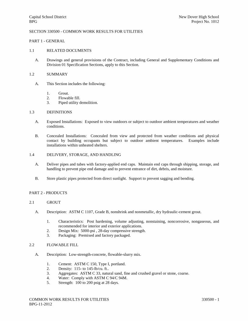
Capital School District New Dover High School BPG Project No. 1012
COMMON WORK RESULTS FOR UTILITIES BPG-11-2012
330500 - 1
SECTION 330500 - COMMON WORK RESULTS FOR UTILITIES
PART 1 - GENERAL
1.1 RELATED DOCUMENTS
A. Drawings and general provisions of the Contract, including General and Supplementary Conditions and Division 01 Specification Sections, apply to this Section.
1.2 SUMMARY
A. This Section includes the following:
1. Grout. 2. Flowable fill. 3. Piped utility demolition.
1.3 DEFINITIONS
A. Exposed Installations: Exposed to view outdoors or subject to outdoor ambient temperatures and weather conditions.
B. Concealed Installations: Concealed from view and protected from weather conditions and physical contact by building occupants but subject to outdoor ambient temperatures. Examples include installations within unheated shelters.
1.4 DELIVERY, STORAGE, AND HANDLING
A. Deliver pipes and tubes with factory-applied end caps. Maintain end caps through shipping, storage, and handling to prevent pipe end damage and to prevent entrance of dirt, debris, and moisture.
B. Store plastic pipes protected from direct sunlight. Support to prevent sagging and bending.
PART 2 - PRODUCTS
2.1 GROUT
A. Description: ASTM C 1107, Grade B, nonshrink and nonmetallic, dry hydraulic-cement grout.
1. Characteristics: Post hardening, volume adjusting, nonstaining, noncorrosive, nongaseous, and recommended for interior and exterior applications.
2. Design Mix: 5000-psi , 28-day compressive strength. 3. Packaging: Premixed and factory packaged.
2.2 FLOWABLE FILL
A. Description: Low-strength-concrete, flowable-slurry mix.
1. Cement: ASTM C 150, Type I, portland. 2. Density: 115- to 145-lb/cu. ft.. 3. Aggregates: ASTM C 33, natural sand, fine and crushed gravel or stone, coarse. 4. Water: Comply with ASTM C 94/C 94M. 5. Strength: 100 to 200 psig at 28 days.

Capital School District New Dover High School BPG Project No. 1012
COMMON WORK RESULTS FOR UTILITIES BPG-11-2012
330500 - 2
PART 3 - EXECUTION
3.1 PIPED UTILITY DEMOLITION
A. Refer to Division 01 Section "Cutting and Patching" and Division 02 Section "Selective Structure Demolition" for general demolition requirements and procedures.
B. Disconnect, demolish, and remove piped utility systems, equipment, and components indicated to be removed.
1. Piping to Be Removed: Remove portion of piping indicated to be removed and cap or plug remaining piping with same or compatible piping material.
2. Piping to Be Abandoned in Place: Drain piping. Fill abandoned piping with flowable fill, and cap or plug piping with same or compatible piping material.
C. If pipe, insulation, or equipment to remain is damaged in appearance or is unserviceable, remove damaged or unserviceable portions and replace with new products of equal capacity and quality.
3.2 GROUTING
A. Mix and install grout for equipment base bearing surfaces, pump and other equipment base plates, and anchors.
B. Clean surfaces that will come into contact with grout.
C. Provide forms as required for placement of grout.
D. Avoid air entrapment during placement of grout.
E. Place grout, completely filling equipment bases.
F. Place grout on concrete bases and provide smooth bearing surface for equipment.
G. Place grout around anchors.
H. Cure placed grout.
END OF SECTION 330500

Capital School District New Dover High School BPG Project No. 1012
STORM UTILITY DRAINAGE PIPING BPG-11-2012
334100 - 1
SECTION 334100 - STORM UTILITY DRAINAGE PIPING
PART 1 - GENERAL
1.1 RELATED DOCUMENTS
A. Drawings and general provisions of the Contract, including General and Supplementary Conditions and Division 01 Specification Sections, apply to this Section.
1.2 SUMMARY
A. This Section includes gravity-flow, nonpressure storm drainage outside the building, with the following components:
1. Precast concrete manholes. 2. Trench drain 3. Storm drain pipe and appurtenances
1.3 PERFORMANCE REQUIREMENTS
A. Gravity-Flow, Nonpressure, Drainage-Piping Pressure Rating: 10-foot head of water. Pipe joints shall be at least watertight, unless otherwise indicated.
1.4 SUBMITTALS
A. Product Data: For the following:
1. Storm drain pipe.
B. Shop Drawings: For the following:
1. Manholes: Include plans, elevations, sections, details, and frames and covers. 2. Catch Basins and Stormwater Inlets. Include plans, elevations, sections, details, and frames,
covers, and grates. 3. Stormwater Detention Structures: Include plans, elevations, sections, details, frames and covers,
design calculations, and concrete design-mix report.
C. Field quality-control test reports.
1.5 DELIVERY, STORAGE, AND HANDLING
A. Protect pipe, pipe fittings, and seals from dirt and damage.
B. Handle manholes according to manufacturer's written rigging instructions.
C. Handle catch basins and stormwater inlets according to manufacturer's written rigging instructions.
D. Handle downspout boots according to manufacturer’s written instructions.
1.6 PROJECT CONDITIONS
A. Interruption of Existing Storm Drainage Service: Do not interrupt service to facilities occupied by Owner or others unless permitted under the following conditions and then only after arranging to provide temporary service according to requirements indicated:

Capital School District New Dover High School BPG Project No. 1012
STORM UTILITY DRAINAGE PIPING BPG-11-2012
334100 - 2
1. Notify Construction Manager Owner no fewer than five days in advance of proposed interruption of service.
2. Do not proceed with interruption of service without Construction Manager's written permission.
B. Site Information: Perform site survey, research public utility records, and verify existing utility locations. Verify that Storm Drainage System piping may be installed in compliance with original design and referenced standards. 1. Locate existing Storm Drainage System piping and structures that are to be abandoned and closed.
PART 2 - PRODUCTS
2.1 MANUFACTURERS
A. In other Part 2 articles where titles below introduce lists, the following requirements apply to product selection:
1. Available Manufacturers: Subject to compliance with requirements, manufacturers offering products that may be incorporated into the Work include, but are not limited to, manufacturers specified.
2.2 PIPING MATERIALS
A. Refer to Part 3 "Piping Applications" Article for applications of pipe, fitting, and joining materials.
2.3 PE PIPE AND FITTINGS
A. Corrugated PE Drainage Pipe and Fittings NPS 48 and Smaller: AASHTO M 252M, Type S, with smooth waterway for coupling joints.
1. Watertight Couplings: PE sleeve with ASTM D 1056, Type 2, Class A, Grade 2 gasket material that mates with tube and fittings.
2. Corrugated PE Pipe and Fittings NPS 12 to NPS 48: AASHTO M 294M, Type S, with smooth waterway for coupling joints.
3. Watertight Couplings: PE sleeve with ASTM D 1056, Type 2, Class A, Grade 2 gasket material that mates with pipe and fittings.
B. Corrugated PE Pipe and Fittings NPS 56 and NPS 60: AASHTO MP7, Type S, with smooth waterway for coupling joints.
1. Watertight Couplings: PE sleeve with ASTM D 1056, Type 2, Class A, Grade 2 gasket material that mates with pipe and fittings.
2.4 REINFORCED CONCRETE PIPE:
1. Materials shall be in accordance with ASSHTO M-170. 2. Pipe class shall be Class III unless otherwise indicated on the drawings. 3. Joints to be tongue and groove. 4. Joining material may be either:
a. Portland cement mortar consisting of 1 part Portland cement, 2 parts sand and enough water to provide a workable mix, or
b. Bitumastic joint filler equal to Ram-Neck.

Capital School District New Dover High School BPG Project No. 1012
STORM UTILITY DRAINAGE PIPING BPG-11-2012
334100 - 3
5. Joints shall be watertight under full flow conditions.
2.5 PVC GRAVITY SEWER PIPING:
1. Pipe and Fittings: ASTM F 679, T-2 wall thickness, PVC gravity sewer pipe with bell-and-spigot ends and with integral ASTM F 477, elastomeric seals for gasketed joints.
2.6 NONPRESSURE-TYPE PIPE COUPLINGS
A. Comply with ASTM C 1173, elastomeric, sleeve-type, reducing or transition coupling, for joining underground nonpressure piping. Include ends of same sizes as piping to be joined, and corrosion-resistant-metal tension band and tightening mechanism on each end.
B. Sleeve Materials:
1. For Concrete Pipes: ASTM C 443, rubber. 2. For Dissimilar Pipes: ASTM D 5926, PVC or other material compatible with pipe materials being
joined.
2.7 MANHOLES
A. Precast Concrete Manholes: ASTM C 478, precast reinforced concrete, of depth indicated with provision for rubber gasket joints.
1. Base Section: 8-inch minimum thickness for floor slab and 5-inch minimum thickness for walls and base riser section, and having a separate base slab or base section with integral floor.
2. Riser Sections: 5-inch minimum thickness; 48-inch diameter, and lengths to provide depth indicated.
3. Top Section: Eccentric cone type, unless concentric cone or flat-slab-top type is indicated. Top of cone to match grade rings.
4. Grade Rings: Provide 2 or 3 reinforced concrete rings, with 12 maximum inches total thickness and match 24-inch diameter frame and cover.
5. Gaskets: ASTM C 443, rubber. 6. Steps: Cast into base, riser, and top sections sidewall at 12-to 16-inch intervals. 7. Pipe Connectors: ASTM C 923, resilient, of size required, for each pipe connecting to base
section. 8. Channel and Bench: Concrete or Brick. 9. Coat Exterior Surface with two (2) coats of coal-tar epoxy, 15 mil. Minimum thickness.
B. Manhole Steps: Wide enough for a man to place both feet on one step and designed to prevent lateral slippage off the step.
1. Material: Steel-reinforced plastic. 2. Manhole Frames and Covers: ASTM A 536, Grade 60-40-18, heavy-duty, ductile iron, 24-inch
inside diameter by 7- to 9-inch riser with 4-inch minimum width flange, and 26-inch-diameter cover, indented top design, with lettering "STORMDRAIN" cast into cover.
2.8 CATCH BASINS & INLETS
A. Standard Precast Concrete Catch Basins & inlets: ASTM C 478, precast, reinforced concrete, of depth indicated, with provision for sealant joints.
1. Catch basins & inlets shall be according to the local utility standard as noted on the structure schedule.

Capital School District New Dover High School BPG Project No. 1012
STORM UTILITY DRAINAGE PIPING BPG-11-2012
334100 - 4
1. All materials for catch basins, steps, frames and grates, curb inlets and other appurtences and incidentals shall conform to Section 708 of DelDOT Specifications and Standard Details for structures noted as DelDOT structures on the plans.
B. Standard PVC Surface Drainage Inlets and In-Line Drains as indicated on the drawings.
1. Ductile Iron Grates shall be considered an integral part of the surface drainage structure and shall be furnished by the same manufacturer.
2. Structures shall be as manufactured by Nyloplast a division of Advanced Drainage Systems, Inc. or approved equal.
2.9 STORMWATER DETENTION STRUCTURES
A. Cast-in-Place Concrete, Stormwater Detention Structures: Construct of reinforced-concrete bottom, walls, and top; designed according to ASTM C 890 for A-16 (ASSHTO HS20-44), heavy-traffic, structural loading; of depth, shape, dimensions, and appurtenances indicated.
1. Ballast: Increase thickness of concrete, as required to prevent flotation. 2. Steps: Individual FRP steps, FRP ladder, or ASTM A 615/A 615M, deformed, 1/2-inch steel
reinforcing rods encased in ASTM D 4101, PP, wide enough to allow worker to place both feet on 1 step and designed to prevent lateral slippage off of step. Cast or anchor steps into sidewalls at 12- to 16-inch intervals. Omit steps if total depth from floor of structure to finished grade is less than 36 inches.
B. Manhole Frames and Covers: ASTM A 536, Grade 60-40-18, ductile-iron castings designed for heavy-duty service Include indented top design with lettering "STORM SEWER" cast into cover.
2.10 CONCRETE
A. General: Cast-in-place concrete according to ACI 318, and the following:
1. Cement: ASTM C 150, Type II. 2. Fine Aggregate: ASTM C 33, sand. 3. Coarse Aggregate: ASTM C 33, crushed gravel. 4. Water: Potable.
B. Portland Cement Design Mix: 4000 psi minimum, with 0.45 maximum water/cementitious materials ratio.
1. Reinforcing Fabric: ASTM A 185/A 185M, steel, welded wire fabric, plain. 2. Reinforcing Bars: ASTM A 615/A 615M, Grade 60 (420 MPa) deformed steel.
C. Manhole Channels and Benches: Factory or field formed from concrete. Portland cement design mix, 4000 psi minimum, with 0.45 maximum water/cementitious materials ratio. Include channels and benches in manholes.
1. Channels: Concrete invert, formed to same width as connected piping, with height of vertical sides to three-fourths of pipe diameter. Form curved channels with smooth, uniform radius and slope.
a. Invert Slope: 1 percent through manhole.
2. Benches: Concrete, sloped to drain into channel.
a. Slope: 4 percent.

Capital School District New Dover High School BPG Project No. 1012
STORM UTILITY DRAINAGE PIPING BPG-11-2012
334100 - 5
D. Ballast and Pipe Supports: Portland cement design mix, 3000 psi minimum, with 0.58 maximum water/cementitious materials ratio.
1. Reinforcing Fabric: ASTM A 185/A 185M, steel, welded wire fabric, plain. 2. Reinforcing Bars: ASTM A 615/A 615M, Grade 60 (420 MPa) deformed steel.
2.11 POLYMER-CONCRETE, CHANNEL DRAINAGE SYSTEMS
A. General Requirements for Polymer-Concrete, Channel Drainage Systems: Modular system of precast, polymer-concrete channel sections, grates, and appurtenances; designed so grates fit into channel recesses without rocking or rattling. Include quantity of units required to form total lengths indicated.
B. Basis-of-Design Product: Subject to compliance with requirements, provide ACO Klassik KS100S sloped channel with ADA compliant stainless steel grates (Class A) at locations shown on the plans or approved comparable product. Provide ACO Sport System 3000 neutral channel with in-line catch basins around the straight and curved areas of the running track as shown on the plans. Provide ACO Sport System 4000 with in-line catch basins and ADA compliant stainless steel grates at Auxiliary Field, baseball field and softball field at the locations shown on the plans.
C. Sloped and Neutral Invert, Polymer-Concrete Systems:
1. Channel Sections:
a. Interlocking-joint, precast, modular units with end caps. b. 4-inch inside width and deep, rounded bottom. Sloped channels shall have a built-in invert
slope of 0.6 percent. Provide outlets in quantities, sizes, and locations indicated. Bottom outlets are to be used unless shown otherwise. Outlets shall include fitting required to transition from oval to round.
c. Extension sections necessary for required depth. d. Frame: Include stainless steel frame for grate.
2. Grates:
a. Manufacturer's designation ACO Type with ADA compliant slotted openings suitable for use in pedestrian locations that fit recesses in channels.
b. Grates shall be removable for easy access to the channel in order to maintain and clean the system.
c. Material: Stainless steel.
3. Covers: Solid gray iron if indicated. 4. Locking Mechanism: Manufacturer's standard device for securing grates to channel sections.
2.12 FIBERGLASS, PREFABRICATED TRENCH DRAINAGE SYSTEMS
A. General Requirements for Fiberglass, Trench Drainage Systems: Prefabricated system of fiberglass molded into smooth radius sections, grates, and appurtenances; designed so grates fit into channel recesses without rocking or rattling. Include quantity of units required to form total lengths indicated.
B. Basis-of-Design Product: Subject to compliance with requirements, provide DuraTrench true radius sloped channel, with ADA compliant stainless steel grates (Class A) as manufactured by Eric’sons at locations shown on the plans or approved comparable product.
Eric’sons 574C Industrial Way N. Dallas, GA 30132 (770) 505-6575

Capital School District New Dover High School BPG Project No. 1012
STORM UTILITY DRAINAGE PIPING BPG-11-2012
334100 - 6
C. Fiberglass Systems:
1. Channel Sections:
a. Trench drain body shall be composed of polyester fiberglass resin and “E” glass fibers molded into a smooth radius, with built-in invert slope of approximately 1.0 percent.
b. Rounded inside bottom surface, with outlets in quantities, sizes, and locations indicated. c. The trench body shall mate to the smooth radius frame and form a grate seat that shall
accept the specified radius grate. The body shall be supplied with a factory fit top for rail alignment and fastening of the channels in the field ensuring that the rails are cast in a coplanar manner.
d. Shall be frost proof and salt proof. e. Width: 8 inches.
2. Grates:
a. Grating shall be heavy duty with ADA compliant slotted openings suitable for use in pedestrian locations that fit recesses in channels.
b. Grates shall be removable for easy access to the channel in order to maintain and clean the system.
c. Material: Stainless steel.
3. Covers: Solid gray iron if indicated.
4. Sealant: Joints shall be fully sealed with urethane joint sealant. The joint sealant shall be continuous form the top of the joint through the bottom and back to the top on the other side.
5. Locking Mechanism: Manufacturer's standard device for securing grates to channel sections.
2.13 CLEANOUTS
A. Cast-Iron Cleanouts:
1. Manufacturers: Subject to compliance with requirements, available manufacturers offering products that may be incorporated into the Work include, but are not limited to, the following:
a. Josam Company. b. MIFAB, Inc. c. Smith, Jay R. Mfg. Co. d. Tyler Pipe. e. Watts Water Technologies, Inc. f. Zurn Specification Drainage Operation; Zurn Plumbing Products Group.
2. Description: ASME A112.36.2M, round, gray-iron housing with clamping device and round, secured, scoriated, gray-iron cover. Include gray-iron ferrule with inside calk or spigot connection and countersunk, tapered-thread, brass closure plug.
3. Top-Loading Classification(s): Heavy Duty. 4. Sewer Pipe Fitting and Riser to Cleanout: ASTM A 74, Service class, cast-iron soil pipe and
fittings.
B. Plastic Cleanouts:
1. Manufacturers: Subject to compliance with requirements, available manufacturers offering products that may be incorporated into the Work include, but are not limited to, the following:
a. Canplas LLC. b. IPS Corporation. c. Nyloplast, a division of Advanced Drainage Systems, Inc.

Capital School District New Dover High School BPG Project No. 1012
STORM UTILITY DRAINAGE PIPING BPG-11-2012
334100 - 7
d. Plastic Oddities; a division of Diverse Corporate Technologies, Inc. e. Sioux Chief Manufacturing Company, Inc. f. Zurn Light Commercial Products Operation; Zurn Plumbing Products Group.
2. Description: PVC body with PVC threaded plug. Include PVC sewer pipe fitting and riser to cleanout of same material as sewer piping.
PART 3 - EXECUTION
3.1 EARTHWORK
A. Excavation, trenching, and backfilling are specified in Division 31 Section "Earth Moving."
3.2 PIPING APPLICATIONS
A. Pipe couplings and special pipe fittings with pressure ratings at least equal to piping rating may be used in applications below, unless otherwise indicated.
1. Use nonpressure-type flexible couplings where required to join gravity-flow, nonpressure sewer piping, unless otherwise indicated.
a. Flexible or rigid couplings for same or minor difference OD pipes.
b. Join reinforced-concrete sewer piping according to ACPA's "Concrete Pipe Installation Manual" for rubber-gasket joints.
c. Join dissimilar pipe materials with nonpressure-type flexible or rigid couplings.
B. Gravity-Flow, Nonpressure Sewer Piping: Use the following pipe materials for each size range and material as indicated on drawings:
1. NPS 4 and NPS 36 Corrugated PE drainage pipe and fittings, watertight couplings, and coupled joints.
2. Reinforced-Concrete Sewer Pipe and Fittings: ASTM C 76, with groove and tongue ends.
3.3 PIPING INSTALLATION
A. General Locations and Arrangements: Drawing plans and details indicate general location and arrangement of underground storm drainage piping. Location and arrangement of piping layout take design considerations into account. Install piping as indicated, to extent practical. Where specific installation is not indicated, follow piping manufacturer's written instructions.
B. Install piping beginning at low point, true to grades and alignment indicated with unbroken continuity of invert. Place bell ends of piping facing upstream. Install gaskets, seals, sleeves, and couplings according to manufacturer's written instructions for use of lubricants, cements, and other installation requirements.
C. Install manholes for changes in direction unless fittings are indicated. Use fittings for branch connections unless direct tap into existing stormdrain system is indicated.
D. Install proper size increasers, reducers, and couplings where different sizes or materials of pipes and fittings are connected. Reducing size of piping in direction of flow is prohibited.
E. Tunneling: Install pipe under streets or other obstructions that cannot be disturbed by tunneling, jacking, or a combination of both.

Capital School District New Dover High School BPG Project No. 1012
STORM UTILITY DRAINAGE PIPING BPG-11-2012
334100 - 8
F. Install gravity-flow, nonpressure drainage piping according to the following:
1. Install piping pitched down in direction of flow, at minimum slope of 1 percent, unless otherwise indicated.
2. Install piping below frost line. 3. Install corrugated steel piping according to ASTM A 798/A 798M. 4. Install nonreinforced-concrete sewer piping according to ASTM C 1479 and ACPA's "Concrete Pipe Installation Manual." 5. Install reinforced-concrete sewer piping according to ASTM C 1479 and ACPA's "Concrete Pipe Installation Manual." 6. Install PE corrugated sewer piping according to CPPA's "Recommended Installation Practices for Corrugated Polyethylene Pipe and Fittings."
3.4 PIPE JOINT CONSTRUCTION
A. Basic pipe joint construction is specified in Division 33 Section "Common Work Results for Utilities." Where specific joint construction is not indicated, follow piping manufacturer's written instructions.
B. Join gravity-flow, nonpressure drainage piping according to the following:
1. Join nonreinforced-concrete sewer piping according to ASTM C 14 and ACPA's "Concrete Pipe Installation Manual" for rubber-gasket joints.
2. Join reinforced-concrete sewer piping according to ACPA's "Concrete Pipe Installation Manual" for rubber-gasket joints.
3. Join dissimilar pipe materials with nonpressure-type flexible or rigid couplings. 4. Join corrugated PE piping according to CPPA 100 and the following:
a. Use watertight couplings for Type 1, watertight joints.
3.5 MANHOLE INSTALLATION
A. General: Install manholes, complete with appurtenances and accessories indicated.
B. Install precast concrete manhole sections according to ASTM C 891.
3.6 CATCH BASIN INSTALLATION
A. Construct catch basins to sizes and shapes indicated.
B. Set frames and grates to elevations indicated.
3.7 STORMWATER INLET AND OUTLET INSTALLATION
A. Construct inlet head walls, aprons, and sides of reinforced concrete, as indicated.
B. Install outlets that spill onto grade, anchored with concrete, where indicated.
C. Install outlets that spill onto grade, with flared end sections that match pipe, where indicated.
D. Construct energy dissipaters at outlets, as indicated.
3.8 CONCRETE PLACEMENT
A. Place cast-in-place concrete according to ACI 318/318R.
3.9 CONNECTIONS

Capital School District New Dover High School BPG Project No. 1012
STORM UTILITY DRAINAGE PIPING BPG-11-2012
334100 - 9
A. Connect nonpressure, gravity-flow drainage piping in building's storm building drains specified in Division 22.
3.10 CLOSING ABANDONED STORM DRAINAGE SYSTEMS
A. Abandoned Piping: Close open ends of abandoned underground piping indicated to remain in place. Include closures strong enough to withstand hydrostatic and earth pressures that may result after ends of abandoned piping have been closed. Use either procedure below:
1. Close open ends of piping with at least 8-inch- thick, brick masonry bulkheads. 2. Close open ends of piping with threaded metal caps, plastic plugs, or other acceptable methods
suitable for size and type of material being closed. Do not use wood plugs.
B. Abandoned Manholes and Structures: Excavate around manholes and structures as required and use one procedure below:
1. Remove manhole or structure and close open ends of remaining piping. 2. Remove top of manhole or structure down to at least 36 inches below final grade. Fill to within 12
inches of top with stone, rubble, gravel, or compacted dirt. Fill to top with concrete.
C. Backfill to grade according to Division 31 Section "Earth Moving."
3.11 IDENTIFICATION
A. Materials and their installation are specified in Division 31 Section "Earth Moving." Arrange for installation of green warning tape directly over piping and at outside edge of underground structures.
1. Use detectable warning tape over nonferrous piping and over edges of underground structures.
3.12 FIELD QUALITY CONTROL
A. Inspect interior of piping to determine whether line displacement or other damage has occurred. Inspect after approximately 24 inches of backfill is in place, and again at completion of Project.
1. Submit separate reports for each system inspection. 2. Defects requiring correction include the following:
a. Alignment: Less than full diameter of inside of pipe is visible between structures. b. Deflection: Flexible piping with deflection that prevents passage of ball or cylinder of size
not less than 92.5 percent of piping diameter. c. Crushed, broken, cracked, or otherwise damaged piping. d. Infiltration: Water leakage into piping. e. Exfiltration: Water leakage from or around piping.
3. Replace defective piping using new materials, and repeat inspections until defects are within allowances specified.
4. Reinspect and repeat procedure until results are satisfactory.
B. Test new piping systems, and parts of existing systems that have been altered, extended, or repaired, for leaks and defects.
1. Do not enclose, cover, or put into service before inspection and approval. 2. Test completed piping systems according to authorities having jurisdiction. 3. Schedule tests and inspections by authorities having jurisdiction with at least 24 hours' notice. 4. Submit separate report for each test.

Capital School District New Dover High School BPG Project No. 1012
STORM UTILITY DRAINAGE PIPING BPG-11-2012
334100 - 10
3.13 CLEANING
A. Clean interior of piping of dirt and superfluous materials. Flush with potable water.
END OF SECTION 334100

Capital School District New Dover High School BPG Project No. 1012
STORM UTILITY DRAINAGE PIPING BPG-11-2012
334100 - 1
SECTION 334600 - SUBDRAINAGE
PART 1 - GENERAL
1.1 RELATED DOCUMENTS
A. Drawings and general provisions of the Contract, including General and Supplementary Conditions and Division 01 Specification Sections, apply to this Section.
1.2 SUMMARY
A. This work shall consist of providing and placing a drainage system comprised of a geo-composite, pre-fabricated, water collection system (collection system) and the associated water transport system (trans-port pipes) as described in the plans. The drainage system shall be installed in accordance with these specifications and in close conformity with the locations and dimensions as shown on the plans or speci-fied by the engineer. The quantities of drainage system materials as shown on the plans may be in-creased or decreased at the discretion of the engineer based on actual site conditions that occur during construction of the project. Such variations in quantity will not be considered as alterations in the details of construction or a change in the character of the work.
B. This Section includes subdrainage systems for the following: 1. Athletic fields.
1.3 DEFINITIONS
A. HDPE: High-density polyethylene plastic.
B. PE: Polyethylene plastic.
C. PP: Polypropylene plastic.
D. PVC: Polyvinyl chloride plastic.
E. Subdrainage: Drainage system that collects and removes subsurface or seepage water.
1.4 SUBMITTALS
A. Product Data: For the following:
1. Perforated-wall pipe and fittings. 2. Solid-wall pipe and fittings. 3. Drainage conduits. 4. Drainage panels. 5. Geotextile filter fabrics.
B. Approval of waterproofing manufacturer's service agent for use of drainage panels against and for waterproofing membrane protection.

Capital School District New Dover High School BPG Project No. 1012
STORM UTILITY DRAINAGE PIPING BPG-11-2012
334100 - 2
PART 2 - PRODUCTS
2.1 MANUFACTURERS
A. In other Part 2 articles where titles below introduce lists, the following requirements apply to product selection:
1. Available Manufacturers: Subject to compliance with requirements, manufacturers offering products that may be incorporated into the Work include, but are not limited to, manufacturers specified.
2. Manufacturers: Subject to compliance with requirements, provide products by one of the manufacturers specified.
2.2 PIPING MATERIALS
A. Refer to the "Piping Applications" Article in Part 3 for applications of pipe, tube, fitting, and joining materials.
2.3 PERFORATED-WALL PIPES AND FITTINGS
A. Perforated PE Pipe and Fittings:
1. NPS 6 and Smaller: ASTM F 405 or AASHTO M 252, Type CP; corrugated, for coupled joints. 2. NPS 8 and Larger: ASTM F 667; AASHTO M 252, Type CP; or AASHTO M 294, Type CP;
corrugated; for coupled joints. 3. Couplings: Manufacturer's standard, band type.
2.4 SOLID-WALL PIPES AND FITTINGS
A. PE Drainage Tubing and Fittings: AASHTO M 252, Type S, corrugated, with smooth waterway, for coupled joints.
1. Couplings: AASHTO M 252, corrugated, band type, matching tubing and fittings.
B. PE Pipe and Fittings: AASHTO M 294, Type S, corrugated, with smooth waterway, for coupled joints.
1. Couplings: AASHTO M 294, corrugated, band type, matching tubing and fittings.
C. PVC Sewer Pipe and Fittings: ASTM D 3034, SDR 35, bell-and-spigot ends, for gasketed joints.
1. Gaskets: ASTM F 477, elastomeric seal.
2.5 SPECIAL PIPE COUPLINGS
A. The fittings used with the collection system shall be of a snap together design. In no case shall any product be joined without the use of the manufacturer’s connector designed specifically for the purpose.
2.6 CLEANOUTS
A. PVC Cleanouts: ASTM D 3034, PVC cleanout threaded plug and threaded pipe hub.
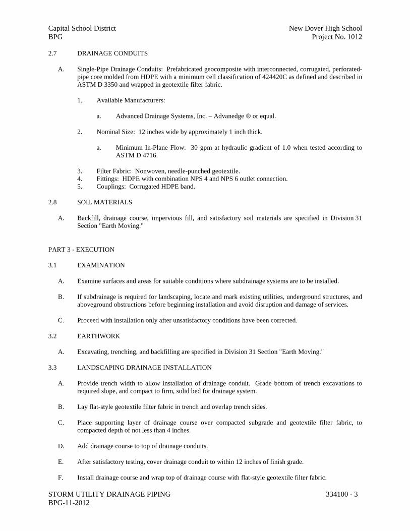
Capital School District New Dover High School BPG Project No. 1012
STORM UTILITY DRAINAGE PIPING BPG-11-2012
334100 - 3
2.7 DRAINAGE CONDUITS
A. Single-Pipe Drainage Conduits: Prefabricated geocomposite with interconnected, corrugated, perforated-pipe core molded from HDPE with a minimum cell classification of 424420C as defined and described in ASTM D 3350 and wrapped in geotextile filter fabric.
1. Available Manufacturers:
a. Advanced Drainage Systems, Inc. – Advanedge ® or equal.
2. Nominal Size: 12 inches wide by approximately 1 inch thick.
a. Minimum In-Plane Flow: 30 gpm at hydraulic gradient of 1.0 when tested according to ASTM D 4716.
3. Filter Fabric: Nonwoven, needle-punched geotextile. 4. Fittings: HDPE with combination NPS 4 and NPS 6 outlet connection. 5. Couplings: Corrugated HDPE band.
2.8 SOIL MATERIALS
A. Backfill, drainage course, impervious fill, and satisfactory soil materials are specified in Division 31 Section "Earth Moving."
PART 3 - EXECUTION
3.1 EXAMINATION
A. Examine surfaces and areas for suitable conditions where subdrainage systems are to be installed.
B. If subdrainage is required for landscaping, locate and mark existing utilities, underground structures, and aboveground obstructions before beginning installation and avoid disruption and damage of services.
C. Proceed with installation only after unsatisfactory conditions have been corrected.
3.2 EARTHWORK
A. Excavating, trenching, and backfilling are specified in Division 31 Section "Earth Moving."
3.3 LANDSCAPING DRAINAGE INSTALLATION
A. Provide trench width to allow installation of drainage conduit. Grade bottom of trench excavations to required slope, and compact to firm, solid bed for drainage system.
B. Lay flat-style geotextile filter fabric in trench and overlap trench sides.
C. Place supporting layer of drainage course over compacted subgrade and geotextile filter fabric, to compacted depth of not less than 4 inches.
D. Add drainage course to top of drainage conduits.
E. After satisfactory testing, cover drainage conduit to within 12 inches of finish grade.
F. Install drainage course and wrap top of drainage course with flat-style geotextile filter fabric.

Capital School District New Dover High School BPG Project No. 1012
STORM UTILITY DRAINAGE PIPING BPG-11-2012
334100 - 4
G. Place layer of flat-style geotextile filter fabric over top of drainage course, overlapping edges at least 4 inches.
H. Fill to Grade: Place satisfactory soil fill material over drainage course. Place material in loose-depth layers not exceeding 6 inches. Thoroughly compact each layer. Fill to finish grade.
3.4 PIPING INSTALLATION
A. Install piping beginning at low points of system, true to grades and alignment indicated, with unbroken continuity of invert. Bed piping with full bearing in filtering material. Install gaskets, seals, sleeves, and couplings according to manufacturer's written instructions and other requirements indicated. Edit first subparagraph below as required for different minimum slope and cover. 1. Landscaping Subdrainage: Install piping pitched down in direction of flow, at a minimum slope
of 0.5 percent and with a minimum cover of 36 inches, unless otherwise indicated. 2. Lay perforated pipe with perforations down.
3. Excavate recesses in trench bottom for bell ends of pipe. Lay pipe with bells facing upslope and
with spigot end entered fully into adjacent bell.
B. CONSTRUCTION REQUIREMENTS
1. The amount of trench excavated at any time shall not exceed the amount of drain that can be set and backfilled completely in one working day. The trench shall be 4 inches wide and at the depth specified in the plans. The collection system shall be centered in the trench, and backfilled with clean very coarse sand or an alternate selected by the engineer.
2. The trench excavations for the collection system and transport pipe shall be to the lines and grades shown on the plans. Over excavation in the bottom of the excavation shall be backfilled to the proper grade with excavated material or sand prior to the placement of the collection system.
3. Fittings shall be installed in accordance with the manufacturer's recommendations.
4. Backfill shall be consolidated in accordance with the plans or as directed by the engineer.
5. Any damaged collection system or transport pipe shall be replaced or repaired by splicing in an undamaged section of like material.
3.5 CONNECTIONS
A. Drawings indicate general arrangement of piping, fittings, and specialties.
B. Connect low elevations of subdrainage system to building's solid-wall-piping storm drainage system.
3.6 IDENTIFICATION
A. Materials and their installation are specified in Division 31 Section "Earth Moving." Arrange for installation of green warning tapes directly over piping.
1. Install PE warning tape or detectable warning tape over ferrous piping. 2. Install detectable warning tape over nonferrous piping and over edges of underground structures.

Capital School District New Dover High School BPG Project No. 1012
STORM UTILITY DRAINAGE PIPING BPG-11-2012
334100 - 5
3.7 FIELD QUALITY CONTROL
A. Testing: After installing drainage course to top of piping, test drain piping with water to ensure free flow before backfilling. Remove obstructions, replace damaged components, and repeat test until results are satisfactory.
3.8 CLEANING
A. Clear interior of installed piping and structures of dirt and other superfluous material as work progresses. Maintain swab or drag in piping and pull past each joint as it is completed. Place plugs in ends of uncompleted pipe at end of each day or when work stops.
END OF SECTION 334600


Capital School District New Dover High SchoolBPG Project No. 1012
ELECTRICAL UNDERGROUND DUCTS/HANDHOLES/PULL BOXES 337119- 1BPG-11-2012 Dimitri J. Ververelli, Inc. – DJVI No. 1019
SECTION 33 71 19
ELECTRICAL UNDERGROUND DUCTS/HANDHOLES/PULL BOXES
PART 1 GENERAL
1.1 RELATED DOCUMENTS AND SECTIONS
A. Drawings and applicable sections of Division 00 - Introductory Information, BiddingRequirements, and Contract Requirements; and Division 01 - General Requirements shall governthe work of this contract unless otherwise specified herein and all requirements shall becompletely fulfilled to the satisfaction of the Engineer and Owner.
1.2 SUMMARY
A. Section Includes:1. Plastic conduit and ductbanks.2. Precast concrete manholes, pull boxes, and splice boxes.3. Underground duct markers.4. Manhole pull/splice box accessories.5. Handholes.6. Transformer vault pad.
B. Related Sections:1. Section 02 41 13 – Selective Site Clearing and Demolition.2. Section 26 05 00 – Common Work Results for Electrical.3. Section 31 20 00 – Earthwork.4. Section 31 25 00 – Soil Erosion and Sediment Control.5. Section 32 92 00 – Seeding and Mulch.
1.3 REFERENCES
A. ASTM International:1. ASTM A48/A48M - Standard Specification for Gray Iron Castings.2. ASTM C857 - Standard Practice for Minimum Structural Design Loading for
Underground Precast Concrete Utility Structures.3. ASTM C858 - Standard Specification for Underground Precast Concrete Utility
Structures.4. ASTM C891 - Standard Practice for Installation of Underground Precast Concrete Utility
Structures.5. ASTM C1037 - Standard Practice for Inspection of Underground Precast Concrete Utility
Structures.
B. Institute of Electrical and Electronics Engineers:1. IEEE C2 - National Electrical Safety Code.

Capital School District New Dover High SchoolBPG Project No. 1012
ELECTRICAL UNDERGROUND DUCTS/HANDHOLES/PULL BOXES 337119- 2BPG-11-2012 Dimitri J. Ververelli, Inc. – DJVI No. 1019
C. National Electrical Manufacturers Association:1. NEMA FB 1 - Fittings, Cast Metal Boxes, and Conduit Bodies for Conduit and Cable
Assemblies.2. NEMA TC 2 - Electrical Polyvinyl Chloride (PVC) Tubing and Conduit.3. NEMA TC 3 - PVC Fittings for Use with Rigid PVC Conduit and Tubing.4. NEMA TC 6 - PVC and ABS Plastic Utilities Duct for Underground Installation.5. NEMA TC 9 - Fittings for ABS and PVC Plastic Utilities Duct for Underground
Installation.6. NEMA TC 10 - PVC and ABS Plastic Communications Duct for Underground
Installation.7. NEMA TC 14 - Filament Wound Reinforced Thermosetting Resin Conduit and Fittings.
D. Underwriters Laboratories Inc.:1. UL 651A - Type EB and A Rigid PVC Conduit and HDPE Conduit.
1.4 SYSTEM DESCRIPTION
A. Interconnected system of conduits, manholes, pull/splice boxes, vaults, and handholes todistribute medium-voltage power, low-voltage power, telephone, and data communications.
B. The majority of the underground conduits, manholes, pull/splice boxes, vaults, and handholes areexisting and shown as “Light” on the Electrical Site Plans. Contractor shall extend the conduitsto their final location (pole fixtures, panels, transformers, switches, receptacles, etc.). Conduitsfor light fixtures shall be extended from existing handholes. Provide new conduit runs as shownon the drawings. Both the power and control conduits shall be extended to the fixture poleswhether or not the control conduit is being used. No existing or new conduit shall be cappedbelow grade unless noted otherwise.
C. Conduit and duct routing and manhole locations are shown in approximate locations unlessdimensions are indicated. Coordinate with the Bid Pac ‘C’ contractor for proper placement ofunderground conduits and to limit excessively long runs.
D. Medium-voltage: Use rigid PVC schedule 40 conduit.
E. Low-voltage: Use rigid PVC schedule 40 conduit.
F. Telephone and data communication: Use rigid PVC schedule 40 conduit.
G. Security systems: Use rigid PVC schedule 40 conduit.
1.5 SUBMITTALS
A. Shop Drawings: Indicate dimensions, reinforcement, size and locations of openings, andaccessory locations for precast manholes and pull/splice boxes, vaults, and handholes.
B. Product Data: Submit for nonmetallic conduit, duct accessories, and manhole, pull/splice box,vaults, and handhole accessories.

Capital School District New Dover High SchoolBPG Project No. 1012
ELECTRICAL UNDERGROUND DUCTS/HANDHOLES/PULL BOXES 337119- 3BPG-11-2012 Dimitri J. Ververelli, Inc. – DJVI No. 1019
C. Manufacturer's Installation Instructions: Submit application conditions and limitations of usestipulated by Product testing agency specified under Regulatory Requirements. Includeinstructions for storage, handling, protection, examination, preparation, and installation ofProduct.
1.6 CLOSEOUT SUBMITTALS
A. Project Record Documents: Record actual routing and elevations of underground conduit andduct, and locations and sizes of manholes, pull/splice boxes, vaults, and handholes.
B. Submit digital photographs of all work prior back filling. Digital copy of photographs to besubmitted to engineer.
1.7 QUALIFICATIONS
A. Manufacturer: Company specializing in manufacturing Products specified in this section withminimum ten years documented experience.
1.8 COORDINATION
A. Coordinate Work with existing underground utilities and structures.
1.9 QUALITY ASSURANCE
A. Comply with the National Electrical Code (NEC) and IEEE C2 – National Electrical SafetyCode (NESC) for components and installation.
B. Provide products that are listed and labeled by a Nationally Recognized Testing Laboratory(NRTL) for the application, installation condition, and the environment in which installed.
1.10 RECEIVING, STORING, AND PROTECTING
A. Receive, store, and protect, and handle products according to NECA 1 – Standard Practices forGood Workmanship in Electrical Construction.
PART 2 PRODUCTS
2.1 PLASTIC CONDUIT
A. Manufacturers:1. Allied Tube and Conduit2. Carlon3. Calconduit Products4. CANTEX
B. Rigid Plastic Conduit: NEMA TC 2, Schedule 40 PVC, with fittings and conduit bodies toNEMA TC 3.

Capital School District New Dover High SchoolBPG Project No. 1012
ELECTRICAL UNDERGROUND DUCTS/HANDHOLES/PULL BOXES 337119- 4BPG-11-2012 Dimitri J. Ververelli, Inc. – DJVI No. 1019
2.2 DUCT SPACERS
A. Furnish duct spacers that provide 3-inch separations between conduits.
B. Manufacturers: Underground Devices "Wunpeece”.
2.3 CONCRETE
A. Use concrete with maximum 1/2 inch coarse aggregate and Type 1 Portland cement (ASTM C150 – Standard Specification for Portland Cement) that has a slump of 6 to 7 inches and acquiresa compressive strength of 5000 psi in 28 days.
2.4 RACEWAY MEASURING/PULLING TAPE
A. Furnish raceway measuring/pulling tape with permanently printed measurements in one-footincrements and minimum 1200 lb average breaking strength.
B. Manufacturer: Greenlee “39243” or equal.
2.5 DUCT PLUGS
A. Provide rubber duct plugs that will produce a positive seal in unused ducts against water and gas.Plugs shall be made of soft, expansible rubber compressed with galvanized steel plates and bolts.
B. Provide plugs at each end of each conduit.
C. Manufacturer: Condux, Jackmoon USA, Inc.
2.6 UNDERGROUND DUCT MARKERS
A. Manufacturers:1. Brimar Pipemarker2. Seton3. Electromark,4. Utility Safeguard, LLC
B. Underground Warning Tape:1. Power: 3 inch wide minimum plastic tape, detectable type, colored red with suitable
warning legend describing buried electrical lines.2. Communication: 3 inch wide minimum plastic tape, detectable type, colored orange with
suitable warning legend describing buried communication lines.
2.7 HANDHOLES
A. Manufacturers:1. Quazite or equal.
B. Description: Molded composite handholes and splice/pull boxes comprising modular,interlocking sections complete with accessories.

Capital School District New Dover High SchoolBPG Project No. 1012
ELECTRICAL UNDERGROUND DUCTS/HANDHOLES/PULL BOXES 337119- 5BPG-11-2012 Dimitri J. Ververelli, Inc. – DJVI No. 1019
C. Enclosures, boxes and covers are required to conform to all test provisions of the most currentANSI/SCTE 77 “Specification for Underground Enclosure Integrity” for Tier 22 applications.When multiple “Tiers” are specified the boxes must physically accommodate and structurallysupport compatible covers while possessing the highest Tier rating. All covers are required tohave the Tier level rating embossed on the surface. In no assembly can the cover design loadexceed the design load of the box. All components in an assembly (box and cover) aremanufactured using matched surface tooling. Independent third party verification or test reportsstamped by a registered Professional Engineer certifying that all test provisions of thisspecification have been met are required with each submittal.
D. Shape: Square, rectangular, as indicated on drawings.
E. Nominal Inside Dimensions: As indicated on drawings.
F. Inside Depth: As indicated on drawings.
G. Wall Thickness: As indicated on drawings.
H. Covers: Molded composite with stainless steel tamperproof fasteners. Furnish cover markedELECTRIC and TELECOMMUNICATION to indicate utility.
I. Duct Entry Provisions: Single duct knockouts, window knockouts.
J. Duct Entry Locations: At each end and each side, as indicated on drawings or as required forconduit routing.
K. Duct Entry Size: To match conduit size.
L. All handholes and splice/pull boxes to have solid bottoms and gasketing.
2.8 MANHOLE AND SPLICE/PULL BOX LID AND FRAME
A. Material shall conform to ASTM A48 – Standard Specification for Gray Iron Castings, Class35B.
B. Frame and lid shall be suitable for AASHTO HS-20 wheel loads.
C. Minimum clear opening through the frame will be 30 inches.
D. Furnish cover marked ELECTRIC.
E. Provide (1) frame and lid for each power manhole and splice/pull box.
F. Manufacturer: Neenah Foundry Company, Model R-1640-C1 or equal.
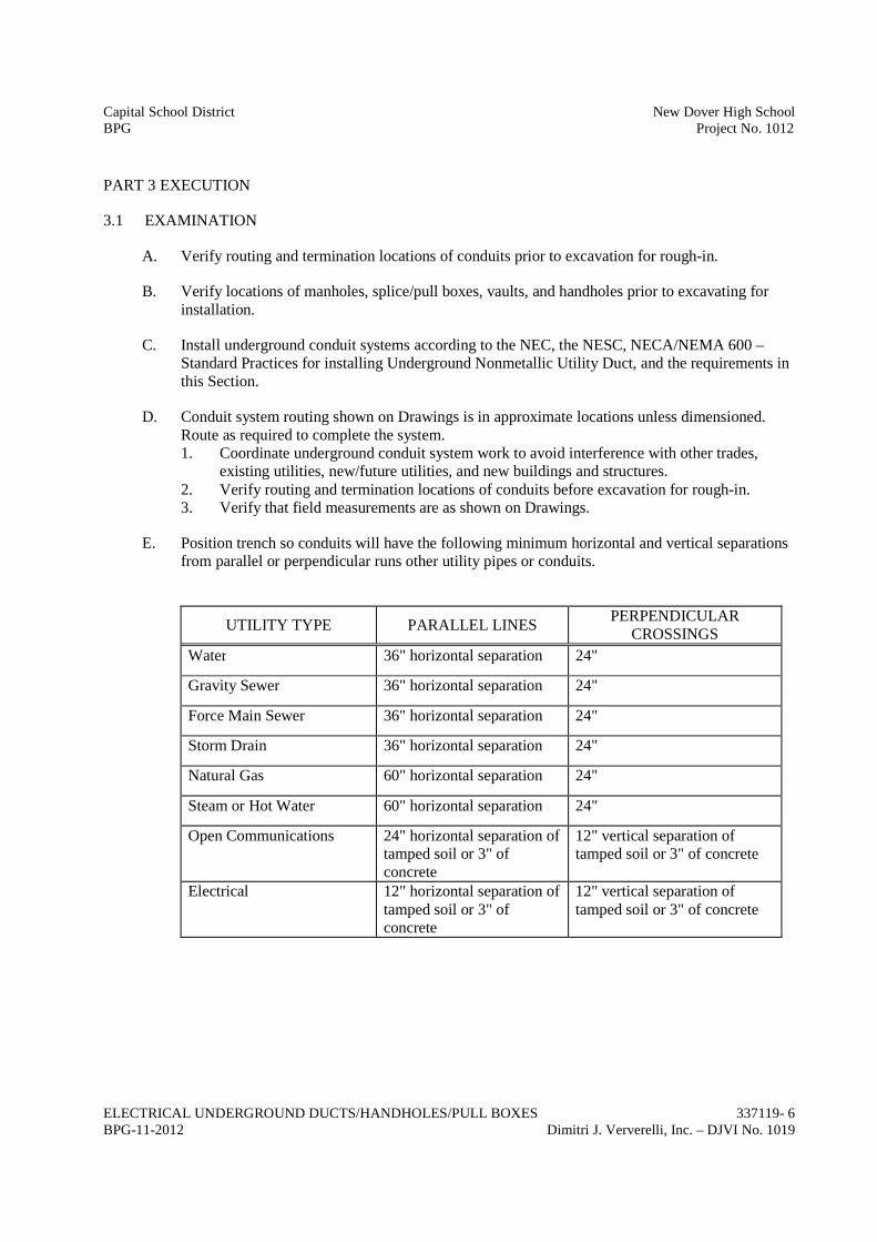
Capital School District New Dover High SchoolBPG Project No. 1012
ELECTRICAL UNDERGROUND DUCTS/HANDHOLES/PULL BOXES 337119- 6BPG-11-2012 Dimitri J. Ververelli, Inc. – DJVI No. 1019
PART 3 EXECUTION
3.1 EXAMINATION
A. Verify routing and termination locations of conduits prior to excavation for rough-in.
B. Verify locations of manholes, splice/pull boxes, vaults, and handholes prior to excavating forinstallation.
C. Install underground conduit systems according to the NEC, the NESC, NECA/NEMA 600 –Standard Practices for installing Underground Nonmetallic Utility Duct, and the requirements inthis Section.
D. Conduit system routing shown on Drawings is in approximate locations unless dimensioned.Route as required to complete the system.1. Coordinate underground conduit system work to avoid interference with other trades,
existing utilities, new/future utilities, and new buildings and structures.2. Verify routing and termination locations of conduits before excavation for rough-in.3. Verify that field measurements are as shown on Drawings.
E. Position trench so conduits will have the following minimum horizontal and vertical separationsfrom parallel or perpendicular runs other utility pipes or conduits.
UTILITY TYPE PARALLEL LINESPERPENDICULAR
CROSSINGS
Water 36" horizontal separation 24"
Gravity Sewer 36" horizontal separation 24"
Force Main Sewer 36" horizontal separation 24"
Storm Drain 36" horizontal separation 24"
Natural Gas 60" horizontal separation 24"
Steam or Hot Water 60" horizontal separation 24"
Open Communications 24" horizontal separation oftamped soil or 3" ofconcrete
12" vertical separation oftamped soil or 3" of concrete
Electrical 12" horizontal separation oftamped soil or 3" ofconcrete
12" vertical separation oftamped soil or 3" of concrete

Capital School District New Dover High SchoolBPG Project No. 1012
ELECTRICAL UNDERGROUND DUCTS/HANDHOLES/PULL BOXES 337119- 7BPG-11-2012 Dimitri J. Ververelli, Inc. – DJVI No. 1019
3.2 EXCAVATION AND BACKFILL
A. Make excavation for manholes, splice/pull boxes, vaults, and handholes to depth required and toprovide solid bearing.
B. Grade trenches for underground conduits to a minimum of 4 inches per 100 ft. toward precastsplice/pull boxes and manholes.
C. Keep excavation dry during installation of work.
D. Make trenches of sufficient width to receive work to be installed.
E. Backfill excavations for manholes, splice/pull boxes, vaults, and handholes in 6 inch layers; usesoil excavated; remove roots, rocks and sharp objects. Provide coarse sand as required foradditional backfill material.
F. Moisture condition backfill soil and compact in accordance with ASTM D 1557 to 95% ofmaximum density under paved areas and 90% of maximum density under unpaved areas.
G. Overfill excavations to allow for settlement.
3.3 INSTALLATION
A. Installation shall include delivery, unloading, setting in place, coring through walls or otherstructures where required. Installation shall be performed in accordance with applicablestandards, codes, requirements and recommendations of National, State and Local authoritieshaving jurisdiction, the N.E.C. and OSHA.
B. All equipment, etc., shall be firmly installed, plumb and square.
C. All conduits should be left clean, dry and free of debris or other obstructions.
D. At completion of manhole, splice/pull box, vault, handhole, and conduit installation, the interiorsshall be left dry and clean of dirt, mortar, concrete, and other debris.
E. The top of installed manholes, splice/pull boxes and vaults shall be flush with the finished gradein the area. A minimum installation of a 6” collar with lid is required. Provide 6” and 12” gradering riser castings as required to elevate cover flush with finished grade.
F. The manhole, and splice/pull box cover/lid shall be bolted/anchored to the top of the installedgrade ring with ½” galvanized hardware.
G. All conduit entry into manholes, splice/pull boxes, vaults, and handholes shall be accomplishedby way of core-boring holes thru the walls to enable a tight and proper seal around all conduits.
H. Make changes in direction of conduit runs using long sweep bends.
I. Support conduits with duct spacers.

Capital School District New Dover High SchoolBPG Project No. 1012
ELECTRICAL UNDERGROUND DUCTS/HANDHOLES/PULL BOXES 337119- 8BPG-11-2012 Dimitri J. Ververelli, Inc. – DJVI No. 1019
J. Anchor conduits to bottom of trench using reinforcing steel and wire at intervals not exceeding10 ft.
K. Test each conduit for blockage or deformation after backfilling.1. Use a flexible mandrel/scraper not less than 12 in. long with a diameter approximately 1/4
in. less than the inside diameter of the duct.2. Pull a mandrel behind a brush with stiff bristles.3. Replace any duct section found blocked or deformed.4. Place underground warning tape in backfill 12 inches below the surface.5. Install measuring and pulling tape in each duct. Leave not less than 48 inches of slack at
each end of the tape. Secure each end of tape.
L. Install conduit with minimum slope of 4 inches per 100 feet (0.33 percent). Slope conduit towardprecast manholes, vaults, and splice/pull boxes and away from building entrances.
M. Cut conduit square using saw or pipe cutter; de-burr cut ends.
N. Insert conduit to shoulder of fittings; fasten securely.
O. Join nonmetallic conduit using adhesive as recommended by manufacturer.
P. Wipe nonmetallic conduit dry and clean before joining. Apply full even coat of adhesive toentire area inserted in fitting. Allow joint to cure for 20 minutes, minimum.
Q. Install no more than equivalent of two 90-degree bends between pull points.
R. Install fittings to accommodate expansion and deflection.
S. Terminate conduit at precast manhole, vault, and splice/pull box entries using end bell.1. For conduits installed through holes cut by the contractor, pack opening with non-shrink
grout. Feather the edge of the grout around each bell and conform to the curvature of thebell end. Remove sharp edges and projections and fill voids within 6 inches of bell ends.
T. Stagger conduit joints vertically in horizontal runs.
U. Securely anchor conduit to prevent movement during backfilling.
V. Provide suitable pull string in each empty conduit except sleeves and nipples.
W. Swab conduit. Use suitable caps to protect installed conduit against entrance of dirt andmoisture.
X. Backfill trenches in accordance with Section 31 20 00.
3.4 INSTALLATION – HANDHOLE
A. Excavate for handhole installation in accordance with Section 31 23 16.
B. Install and seal precast sections in accordance with ASTM C891.

Capital School District New Dover High SchoolBPG Project No. 1012
ELECTRICAL UNDERGROUND DUCTS/HANDHOLES/PULL BOXES 337119- 9BPG-11-2012 Dimitri J. Ververelli, Inc. – DJVI No. 1019
C. Install handholes plumb.
D. Backfill handhole excavation in accordance with Section 31 23 23.
E. HANDHOLES INSTALLED IN GRASS LANDSCAPE AREAS- The top of installed hand-holes (concrete envelope) shall be flush with the existing grade in the area. The grading from theedge of the concrete envelope shall be accomplished by fanning topsoil away from the concreteenvelope at a 2” drop in grade over a 10 ft. radius of the lid itself.
F. HANDHOLES INSTALLED IN CONCRETE SIDEWALKS AND PAVED/ROADWAYAREAS- The top of installed hand-holes (concrete envelope) shall be flush with the existinggrade in the area.
G. All Quazite hand-holes shall be installed per Quazite Field Applications Instruction Sheet,which defines an approximate 10” wide X 12” deep sloped concrete ring to be installed aroundthe entire perimeter of the hand-hole itself, for additional support in the event of heavy loadingfrom motor vehicles, tractors, mowers, and other similar equipment.
H. All hand-holes shall be installed as per all standard Strongwell Corp. Quazite Product FieldApplications sheets.
I. All conduit entry into hand-holes shall be accomplished utilizing a Greenlee Hydraulic KnockoutPunch Driver of appropriate size, or a Greenlee carbide-Grit hole-saw as per Quazite FieldApplications Instruction Sheets for hand-holes. All conduits shall be terminated at hand-holewith Carlon box adapters on the interior and glued to a PVC bell end of the conduit on theexterior.
3.5 GROUNDING
A. Install 5/8” diameter x 8 feet copper clad steel ground rod in each manhole, vault, and splice/pullbox prior to setting top. Provide ground ring as shown in the Drawings.
END OF SECTION


Capital School District New Dover High SchoolBPG Project No. 1012
ELECTRICAL UTILITY SERVICES 337173 - 1BPG-11-2012 Dimitri J. Ververelli, Inc. – DJVI No. 1019
SECTION 33 71 73
ELECTRICAL UTILITY SERVICES
PART 1 GENERAL
1.1 RELATED DOCUMENTS AND SECTIONS
A. Drawings and applicable sections of Division 00 - Procurement and Contracting Requirementsand Division 01 - General Requirements shall govern the work of this contract unless otherwisespecified herein and all requirements shall be completely fulfilled to the satisfaction of theEngineer and Owner.
B. All specification sections of Division 07 – Thermal and Moisture Protection, Division 21 – FireSuppression, Division 22 – Plumbing, Division 23 – Heating, Ventilating, and Air Conditioning(HVAC), Division 25 – Direct Digital Control Systems for HVAC, Division 26 – Electrical, anddrawings are made part of this contract and shall apply to all work described in this Section.
1.2 SUMMARY
A. Section includes arrangement with Utility Company for permanent electric service; payment ofUtility Company charges for service; service provisions; and utility metering equipment.
B. All work shall be in accordance with the City of Dover Electric Department’s Electrical ServiceHandbook.
C. All conduit shall be inspected by the City of Dover Engineering Department prior to backfilling.
D. The Contractor shall include in his bid and pay the City of Dover Extension Fee prior to startingwork for the City’s portion of the work.
Generally, the City of Dover scope of work is as follows:
Furnish and Install metering cabinet.
E. The Extension Fee shall be submitted to:City of DoverPublic Utilities Department860 Buttner PlaceDover, DE 19984
F. Coordinate and schedule service work with City of Dover Electric Department.City of DoverMunicipal Electric DepartmentGary Lawson, Engineering Fieldman302.242.8459
G. Electrical power for lighting and operation of construction power tools by all trades shall beprovided by Contractor from local utility or Contractor’s on site generator. Contractor shall

Capital School District New Dover High SchoolBPG Project No. 1012
ELECTRICAL UTILITY SERVICES 337173 - 2BPG-11-2012 Dimitri J. Ververelli, Inc. – DJVI No. 1019
provide all safety devices, extension cords, and remote outlets as required by regulations and use.All outlets shall be GFCI type.
H. Temporary lighting and wiring shall be provided by the Contractor in accordance with OSHAregulations.
I. The temporary power shall have the capacity to run construction equipment such as welders andfloor finishing equipment.
J. Contractor shall pay all utility fees for the temporary service.
K. The temporary electric service shall be metered.
1.3 REFERENCES
TBD
1.4 SYSTEM DESCRIPTION
A. Utility Company: City of Dover.
B. System Characteristics: 12,470 volts, three phase, 60 Hertz.
C. Underground Service Provisions: Underground service entrance to building service entranceequipment.1. Utility Raceway Connection: At Utility Company's pad-mounted metering cabinet.2. Utility Service-Entrance Conductor Connection: At Utility Company's pad-mounted
metering cabinet.
1.5 SUBMITTALS
A. Submit Utility-Company-prepared drawings.
1.6 QUALITY ASSURANCE
A. Perform Work in accordance with Utility Company written requirements.
B. Maintain one copy of each document on site.
1.7 FIELD MEASUREMENTS
A. Verify field measurements are as indicated on Drawings.
1.8 COORDINATION
A. Coordinate with utility company, relocation of overhead or underground lines interfering withconstruction. Where power lines are to be relocated, bill utility costs, directly to Owner.

Capital School District New Dover High SchoolBPG Project No. 1012
ELECTRICAL UTILITY SERVICES 337173 - 3BPG-11-2012 Dimitri J. Ververelli, Inc. – DJVI No. 1019
B. Contact utility company regarding charges related to service installation. Include utility chargesin this contract.
C. Utility charges for service installation will be paid by the Contractor.
PART 2 PRODUCTS
2.1 UTILITY METERS
A. Furnished by Utility Company.
2.2 UTILITY METER BASE
A. Furnished by Utility Company and installed by the Contractor.
2.3 METERING TRANSFORMER CABINET
A. Furnished by Utility Company.
2.4 METERING CABINET PAD
A. Furnished and installed by the Contractor.
PART 3 EXECUTION
3.1 EXAMINATION
A. Verify service equipment is ready to be connected and energized.
3.2 INSTALLATION
A. Install service entrance conduits to building service entrance pad mount transformer.
END OF SECTION