new directions in modelling, analysis and design of wdm ... · new directions in modelling,...
TRANSCRIPT
3
New directions in modelling, analysis and design of WDM/OFDM-networks: (I) Optical Switching
Josef Giglmayr
Heinrich-Hertz-Institut fUr Nachrichtentechnik Berlin GmbH Einsteinufer 37, D-I0587 Berlin
E-mail: Giglmayr@hhLde
Abstract
Bearing in mind that a topological representation of a finite graph is a compact space, by the relationships between (Graph)Topology, Algebraic Topology, Group Theory, (Differential)Geometry and Combinatorics a new universe arises for modelling, analysis and design of (telecommunication) networks_ Throughout the present paper, coverings/covering spaces, the lifting problem and quotient graphs are briefly interpreted in terms of the requirements for the combinatorial design of optical switches though the presentation is mainly based on illustrations rather than on a (precise) mathematical description.
Key words: Multi-layer, parallel waveguides, electrodes, spatial all-optical switch, planar alloptical switch, all-optical expander/concentrator, parallel permuters, vertical stacking, graph covering, lifting
1. Introduction
Graph models are fundamental tools in modelling, analysis and design of communication networks. Mathematicians have recognized the limitations of ordinary graph models and developed several generalizations such as pseudographs and hypergraphs, respectively. Pseudographs are multigraphs (=multiple edges between some nodes) with (multiple) self-loops. For example, the de Bruijn directed graph (digraph) B(ll.,D) with D edges between every node-pair and self-loops at some nodes provides the nonblocking simultaneous communication of the node-pairs [1). In contrast, hypergraphs are graphs with more than two nodes for every edge [2). Pseudographs may be applied to model WDM/OFDM-networks consisting of optical fibers interconnecting optical nodes and access nodes (physical layer), respectively. By the partition of access nodes into intersecting subnets a hypergraph is formed (logical layer) [3).
Throughout the paper, a topological approach is applied where finite simple regular graphs (and even infinite, nonregular, multigraphs, pseudographs or hypergraphs) are the most simplest space [4). The next more complicated topological spaces are (compact) surfaces which are of interest once pseudographs are embedded into them. One basic problem of topology is to determine whether there exits a continuos function (and its inverse) between two given topological spaces. Therefore, topology is, roughly speaking, called the geometry of continuous functions. Here the concept of covering projections/covering spaces and of quotient maps/quotient spaces comes in. Throughout an application of topology to networks, these geometric problems have to be tr~ated by means of powerful algebraic methods. The aim of the ongoing work is to deduce some valuable hints for the modelling, analysis and design of WDM/OFDM-networks and their components.
Throughout the paper the application of graph coverings is shown for the design of all-optical switches, expanders and concentrators. However, the most convenient treatment of graph coverings is by voltage graphs [5) which will not be shown in this paper. Another problem are liftings which are briefly mentioned throughout the discussion of switches, expanders and concentrators.
Optical Network Design .nd Modelling H. van As & A. Juk.n (Eds.) © 1998 IFIP. Published by Chapman & Hall
34 Part Two Network planning and design
2. Preliminaries
In the following minor elements from topology (4) and graph theory (5) are collected which are needed to understand the ideas of the paper.
2.1 Graph topology
From the point of view of topology, a graph/network is a rather simple topological space even it may be an infinite, nonregular pseudograph. Note, a topological space (X,A) is a topology A on a set X where A represents a family of subsets of X which satisfies some simple conditions (4).
Coverings
A family A of subsets Ai of X is said to cover X if and only if (iff) UAi = X. In terms of graph theory, a graph 0 is a covering of a graph H iff there exist a map p: V(O) --+ V(H) which induces a one-to-one correspondence between the nodes adjacent to veO and the nodes adjacent to p(v)eH. Then the graph 0 is called the derived graph (5) or the covering space (4).
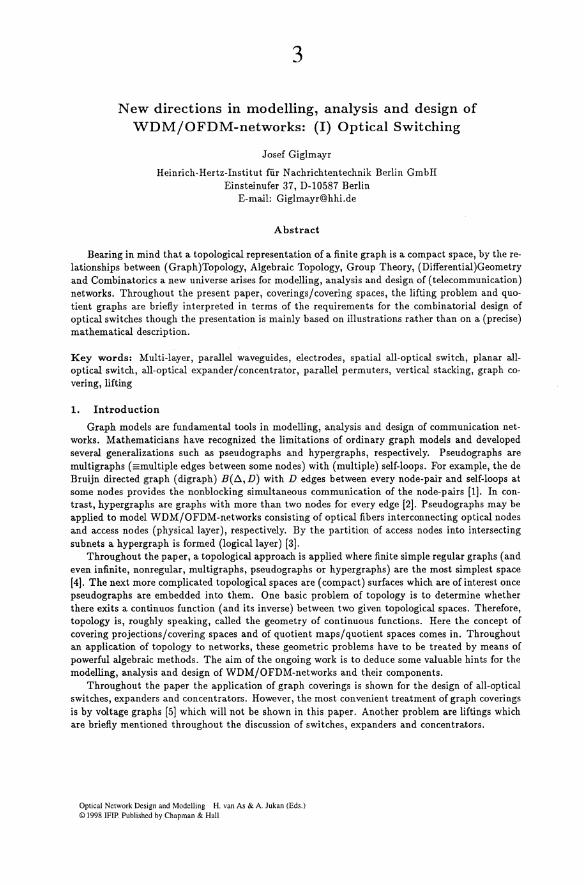
Example 1: The distance-transitive graph/antipodal graph e!2) (Sub-Section 2.2) in Fig. 1 (a) lhs, which equals the 3-cube Q3 (6), is a double cover of K" [Fig. 1 (a) rhs), i.e. K" is contained in Q3 with respect to both coordinates (7). Note, K" covers the ring e" which represents the intersection of the embedded 4-gon prism (Sub-Section 3.2).
Example 2: The bipartite graph K3,3 and e~2) (two connected triangles) both have the same degree.
Then there exist a graph e~2) (two connected hexagons) which cover both subgraphs (8).
'I' 1,0 2,1 ut@J .. ,~ 2 5
DdJ 2
P ,5 2, 3. 6 >j,1 ,6 6,
2,0 1, 3 1 4 2,3 1. 3,2
4,1 3,0 ,1 ~ Ii 3 2
(a) (b)
Fig. 1. Double covers of graphs. (a) The two connected cycles e!2) (= Q3) cover the completely connected graph [(" twice (Example 1). (b) e~2) covers the bipartite graph K3,3 and e~2) (Example 2).
Lifting
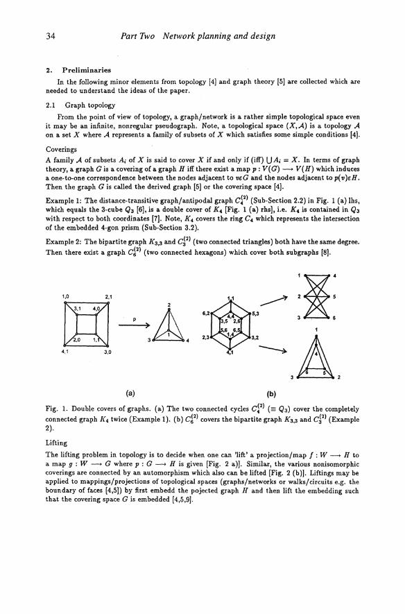
The lifting problem in topology is to decide when one can 'lift' a projection/map f : W --+ H to a map 9 : W --+ 0 where p : 0 --> H is given [Fig. 2 a»). Similar, the various nonisomorphic coverings are connected by an automorphism which also can be lifted [Fig. 2 (b»). Liftings may be applied to mappings/projections of topological spaces (graphs/networks or walks/circuits e.g. the boundary of faces [4,5)) by first embedd the pojected graph H and then lift the embedding such that the covering space 0 is embedded [4,5,9).
New directions in WDMIOFDM-networks 35
Remark 1: By the lifting concept, walks/routings in an N-gon prism switch (Sub-Section 3_1) may be lifted to walks/routings in an embedded mN-gon prism switch (Sub-Section 3.2) and vice versa, walks/routings in the mN -gon prism switch may be based on walks/routings in an N -gon prism switch. However, presently, the routing of the mN-gon prism switch for the rearrangeable nonblocking case is redrawn from an algorithm for cellular arrays [10,11].
(a) (b)
Fig. 2. (a) Lifting of a mapping f by means of the covering projection p to 9 = p-l 0 f [4]. (b) Connection of nonisomorphic coverings by a lifted automorphism, Le. the automorphism a is lifted to the automorphism (3 [12].
2.2 Graph theory
The paper deals with distance-transitive graphs, which are the most symmetric graphs, and some definitions and results, which mainly are due to [13), are collected in the following.
Automorphism
An automorphism of a (simple) graph G = (V, E) (where V is the set of nodes and E the set of edges) is a permutation 1\" of V which has the property that (Il, v) is an edge of G iff (1\"( Il), 1\"( v» is an edge of G, Le. it preserves adjacency.
Distance-transitive graph
A graph G = (V, E) is said to be distance-transitive, if, for any nodes x, y, Il, w;V satisfying d( Il, v) = d(:I:, y) (d is the distance between 2 nodes in terms of the number of edges) there is an automorphism 1\" of G which takes Il to v and x to y. This is the strongest symmetry condition on graphs which allows to reduce its description by the N X N-adjacency matrix via the description by an 3xD + 1-intersection array to a D + 1 X D + I-matrix (D is the diameter)<'-where all the three matrices have the same eigenvalues. Here an interesting eigenvalue problem comes in [14).
Antipodal graph
An antipodal graph G with diameter D has the property that each node veG has an unique (antipodal) node U of distance D from v in G. The antipodal node-pairs in G produce a quotient graph H with a double cover projection p : G ---+ H (Sub-Section 2.1). Any antipodal graph G has circuits of length 2D passing through antipodal node-pairs [15]. Here the 'block system' of a graph comes in, which allows to derive a quotient graph whose nodes correspond with the blocks (Note the intersection of the embedded mN-gon prism switches in Sub-Section 3.2 are antipodal graphs).
Example 3: The completely connected graph [(4 in Fig. 1 (a) is a graph quotient of the 3-cube Q3 and the double triangle d 2) in Fig. 1 (b) is the graph quotient of the double hexagon d 2).
Roughly speaking, the N-gon is a quotient of the N +1-gon.
36 Part Two Network planning and design
3. Concepts and quantities
In the following, the elements of the foregoing Section are applied to some novel components of WDM/OFDM-networks. Although there has been obtained a considerable progress in glas fiber research applications, the crucial points are the nodes of the networks which include optical switches and crossconnects (= a space switch carrying frequency channels), respectively. The space switches presented in the following are aimed to be extended to crossconnects.
3.1 The N-gon prism switch
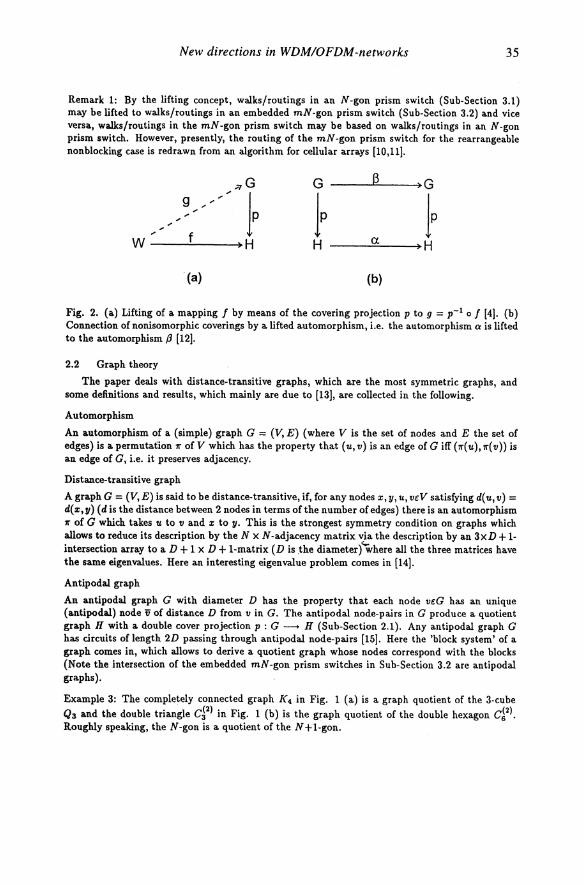
For the purpose of the extension of current all-optical switching principles (16) into the 3-D physical space, the N-gon prism switch (N ;::3) has been introduced which is based on multi-layer architectures and nearest-neighbour interconnected 2x2-switches [17,18,19) (see Fig. 3 for N=4).
Electrodes
1st Layer
2nd Layer
Fig. 3. 3-stage 4-gon prism switch composed of a double-layer, parallel waveguides and electrodes.
The architecture of the N-gon prism switch is described for one stage by (20)
(1)
where Ell is the Kronecker sum (KS) (21), eN is a cycle with N nodes and edges and K2 represents 2 nodes interconnected by one edge. The number of stages (NS), sufficient for the generation of N! (arbitrary) permutations (= rearrangeable nonblocking interconnections) is
NS=N-~ (2)
caused by the isomorphism between the N-gon and the nearest-neighbour interconnection of switches with skew 1 (Fig. 4) (22).
The number of switches per stage (NSW.14g.) is
N N SW.14g• = l2" J (3)
where the 'floor' function l a J is the largest integer less than or equal to a. From Eqs.(2) and (3) we may conclude that the total number of 2x2-switches is
N NSW1ol41 = l2"J(N -1) (4)
which is below the Spanke-Benes minimum N(N - 1)/2 for N odd.
For the proper understanding of the N -gon prism switch the following assumptions are important
New directions in WDMIOFDM-networks 37
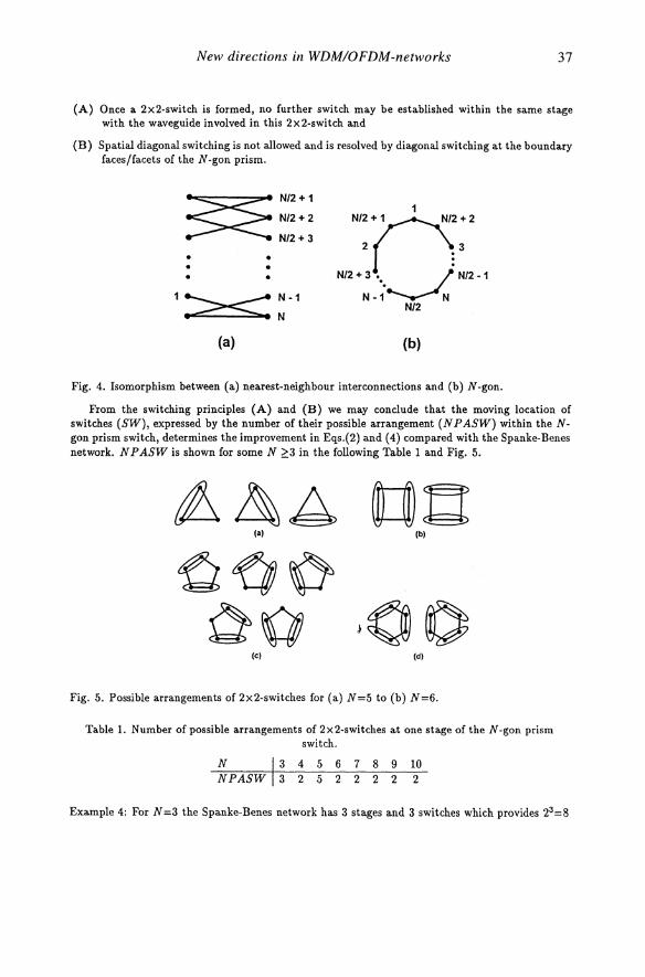
(A) Once a 2x2-switch is formed, no further switch may be established within the same stage with the waveguide involved in this 2x2-switch and
(B) Spatial diagonal switching is not allowed and is resolved by diagonal switching at the boundary faces/facets of the N-gon prism.
~ N/2+ 1
1 N/2 + 2
Nn()+2 N/2+3
2 3 • •
NI2+3 ••• J. NI2·1 • • •
1:>=<: N ·1 N·1 N
N/2 N
(a) (b)
Fig. 4. Isomorphism between (a) nearest-neighbour interconnections and (b) N-gon.
From the switching principles (A) and (B) we may conclude that the moving location of switches (SW), expressed by the number of their possible arrangement (N P ASW) within the Ngon prism switch, determines the improvement in Eqs.(2) and (4) compared with the Spanke-Benes network. N P ASW is shown for some N ~3 in the following Table 1 and Fig. 5.
la) Ib)
Ie) Id)
Fig. 5. Possible arrangements of2x2-switches for (a) N=5 to (b) N=6.
Table 1. Number of possible arrangements of 2X2-switches at one stage of the N-gon prism switch.
10 2
Example 4: For N=3 the Spanke-Benes network has 3 stages and 3 switches which provides 23=8
38 Part Two Network planning and design
sta.tes sufficient to genera.te 3!=6 permuta.tions (16). However, the 3-gon prism switch conta.ins 2 switches a.nd is thus represented by 22=4 sta.tes which is not enough to genera.te 6 permuta.tions. But, a.ccording to Ta.ble 1, the number of possible sta.tes is 3x4=12 which now is sufficient.
Rema.rk 2: In Ta.ble 1 ,the case N =5 has the la.rgest N P ASW (Fig. 5), though no a.dva.nta.ge seems to a.rise in Eq.( 4).
Rema.rk 3: The routing algorithm of the N-gon prism switch is of complexity O(N) a.nd is optimal [ll).
3.2 The embedded N-gon prism switch
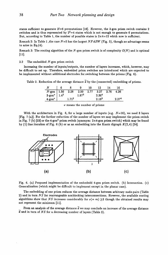
Increasing the number of inputs/outputs, the number of la.yers increases, which, however, ma.y be difficult to set up. Therefore, embedded prism switches a.re introduced which a.re expected to be implemented without a.dditional electrodes for switching between the prisms (Fig. 6).
Ta.ble 2. Reduction of the a.vera.ge dista.nce Ii by the (connected) embedding of prisms.
N 6 8 9 10 12 14 16 N-gon 1.50 2.28 2.50 2.77 3.27 3.76 4.26 3-gonV 1.42 1.873 2.364 4-gonV 1.712 2.183 2.274
v mea.ns the number of prisms
With the a.rchitecture in Fig. 6"for a. la.rge number of inputs (e.g. N=16), we need 8 la.yers [Fig. 7 (a.»). For the further reduction of the number of la.yers we ma.y implement the prism switch in Fig. 7 (b) (23) or the 4-gon2 prism switch (synonym: 2x4-gon prism switch) which ma.y be found by (1) line itera.tion of Fig. 6 (b) or as a.n embedding into the Ka.utz digra.ph K(2,4) (24).
Electrodes
:0: (a) (b) (c)
Fig. 6. (a.) Proposed implementa.tion of the embededd 4-gon prism switch. (b) Intersection. (c) Generaliza.tion (which might be difficult to implement except in the pla.na.r case).
The embedding of one prism reduces the a.vera.ge dista.nce between a.rbitra.ry node-pa.irs (Ta.ble 2) a.nd in turn N S for rea.rra.ngeable nonblocking interconnections. However, the a.va.ilable routing a.lgorithms show tha.t NS increases considera.bly for v(= m) ~3 though the obta.ined results ma.y not represent the minimum Ill).
_ From a.n a.nalysis of the a.vera.ge dista.nce Ii we ma.y conclude a.n increase of the a.vera.ge dista.nce d a.nd in turn of N S for a. decreasing number of la.yers (Ta.ble 3).
New directions in WDMIOFDM-networks 39
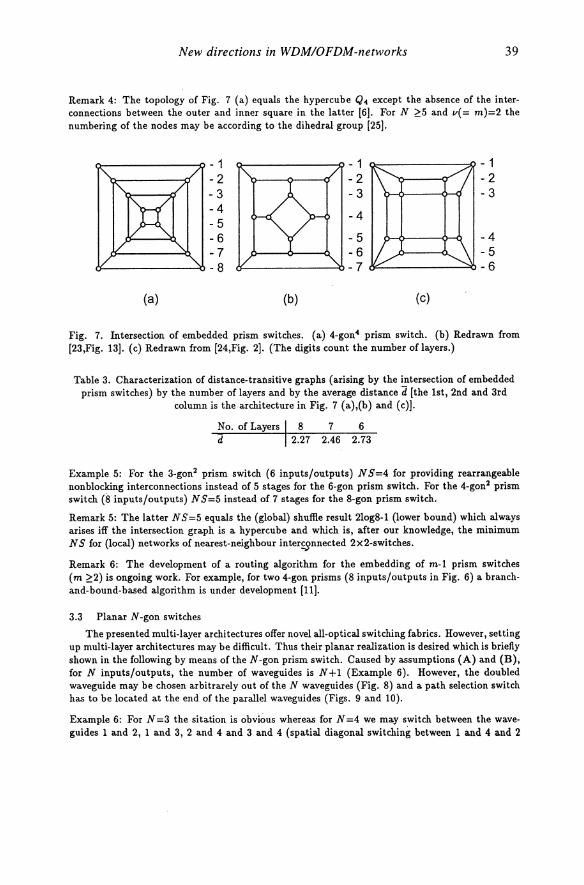
Remark 4: The topology of Fig. 7 (a) equals the hypercube Q4 except the absence of the interconnections between the outer and inner square in the latter [6J. For N ~5 and v( = m )=2 the numbering of the nodes may be according to the dihedral group [25J.
- 1 - 1 - 1 -2 -2 -2 -3 - 3 -3 -4
-4 -5 -6 - 5 -4 -7 -6 - 5 -8 -7 -6
(a) (b) (c)
Fig. 7. Intersection of embedded prism switches. (a) 4-gon4 prism switch. (b) Redrawn from [23,Fig. 13J. (c) Redrawn from [24,Fig. 2J. (The digits count the number of layers.)
Table 3. Characterization of distance-transitive graphs (arising by the intersection of embedded prism switches) by the number oflayers and by the average distance d [the 1st, 2nd and 3rd
column is the architecture in Fig. 7 (a),(b) and (c)J.
No. of Layers I 8 7 6 d 2.27 2.46 2.73
Example 5: For the 3-gon2 prism switch (6 inputs/outputs) N S=4 for providing rearrangeable nonblocking interconnections instead of 5 stages for the 6-gon prism switch. For the 4-gon2 prism switch (8 inputs/outputs) N S=5 instead of 7 stages for the 8-gon prism switch.
Remark 5: The latter N S=5 equals the (global) shuflle result 21og8-1 (lower bound) which always arises iff the intersection graph is a hypercube and which is, after our knowledge, the minimum N S for (local) networks of nearest-neighbour inter~nnected 2x2-switches.
Remark 6: The development of a routing algorithm for the embedding of m-l prism switches (m ~2) is ongoing work. For example, for two 4-gon prisms (8 inputs/outputs in Fig. 6) a branchand-bound-based algorithm is under development [l1J.
3.3 Planar N-gon switches
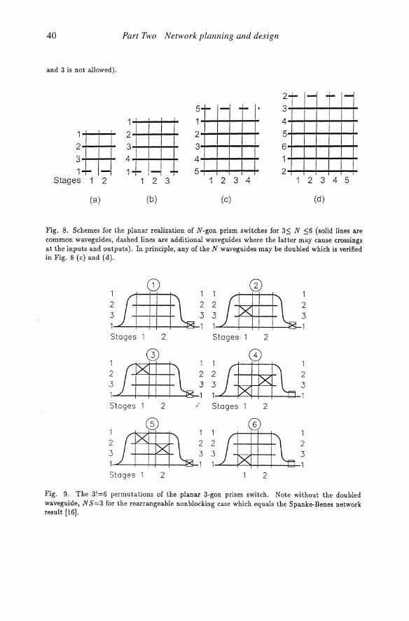
The presented multi-layer architectures offer novel all-optical switching fabrics. However, setting up multi-layer architectures may be difficult. Thus their planar realization is desired which is briefly shown in the following by means of the N-gon prism switch. Caused by assumptions (A) and (B), for N inputs/outputs, the number of waveguides is N+l (Example 6). However, the doubled waveguide may be chosen arbitrarely out of the N waveguides (Fig. 8) and a path selection switch has to be located at the end of the parallel waveguides (Figs. 9 and 10).
Example 6: For N =3 the sitation is obvious whereas for N =4 we may switch between the waveguides 1 and 2, 1 and 3, 2 and 4 and 3 and 4 (spatial diagonal switching between 1 and 4 and 2
40
and 3 is not allowed).
Stages 2
(a)
Part Two Network planning and design
2 3 4
-- I- -r-2 3
(b)
2 5-- 1- -- 3
2+-+-+-+-+ 3+-+-+-+-+ 4+-+-+-+-+ 5 -+--+--+--+--+
2 3 4
(c)
4
5 6
2
-l- I- -,.. -
I
2 3 4 5
(d)
Fig. 8. Schemes for the planar realization of N-gon prism switches for 3::; N ::;6 (solid lines are common waveguides, dashed lines are additional waveguides where the latter may cause crossings at the inputs and outputs). In principle, any of the N waveguides may be doubled which is verified in Fig. 8 (c) and (d).
CD CD
~lllll~HIHII~~ Stages 2 Stages 2
Stages 2 J" Stages 2
Stages 2 2
Fig. 9. The 3!=6 permutations of the planar 3-gon prism switch. Note without the doubled waveguide, N S=3 for the rearrangeable nonblocking case which equals the Spanke-Benes network result [16J.
New directions in WDMIOFDM-networks 41
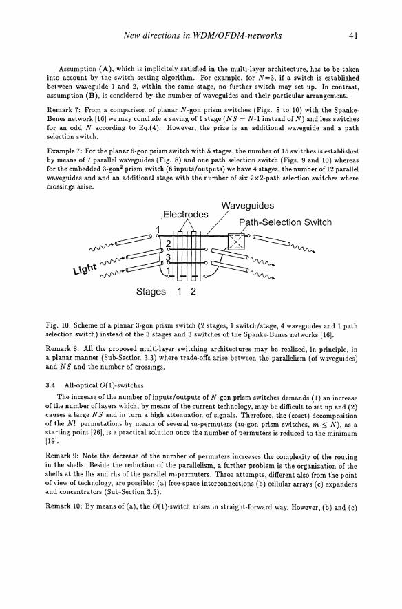
Assumption (A), which is implicitely satisfied in the multi-layer architecture, has to be taken into account by the switch setting algorithm. For example, for N =3, if a switch is established between waveguide 1 and 2, within the same stage, no further switch may set up. In contrast, assumption (B), is considered by the number of waveguides and their particular arrangement.
Remark 7: From a comparison of planar N-gon prism switches (Figs. 8 to 10) with the SpankeBenes network [16) we may conclude a saving of 1 stage (N S = N -1 instead of N) and less switches for an odd N according to Eq.( 4). However, the prize is an additional waveguide and a path selection switch.
Example 7: For the planar 6-gon prism switch with 5 stages, the number of 15 switches is established by means of 7 parallel waveguides (Fig. 8) and one path selection switch (Figs. 9 and 10) whereas for the embedded 3-gon2 prism switch (6 inputs/outputs) we have 4 stages, the number of 12 parallel waveguides and and an additional stage with the number of six 2x2-path selection switches where crossings arise.
Stages 1 2
Fig. 10. Scheme of a planar 3-gon prism switch (2 stages, 1 switch/stage, 4 waveguides and 1 path selection switch) instead of the 3 stages and 3 switches of the Spanke-Benes networks [16).
Remark 8: All the proposed multi-layer switching architectures may be realized, in principle, in a planar manner (Sub-Section 3.3) where trade-offs. arise between the parallelism (of waveguides) and N S and the number of crossings.
3.4 All-optical O( 1 )-switches
The increase of the number of inputs/outputs of N -gon prism switches demands (1) an increase of the number of layers which, by means of the current technology, may be difficult to set up and (2) causes a large N S and in turn a high attenuation of signals. Therefore, the (coset) decomposition of the N! permutations by means of several m-permuters (m-gon prism switches, m ~ N), as a starting point [26), is a practical solution once the number of permuters is reduced to the minimum [19).
Remark 9: Note the decrease of the number of permuters increases the complexity of the routing in the shells. Beside the reduction of the parallelism, a further problem is the organization of the shells at the lhs and rhs of the parallel m-permuters. Three attempts, different also from the point of view of technology, are possible:. (a) free-space interconnections (b) cellular arrays (c) expanders and concentrators (Sub-Section 3.5).
Remark 10: By means of (a), the O(I)-switch arises in straight-forward way. However, (b) and (c)
42 Part Two Network planning and design
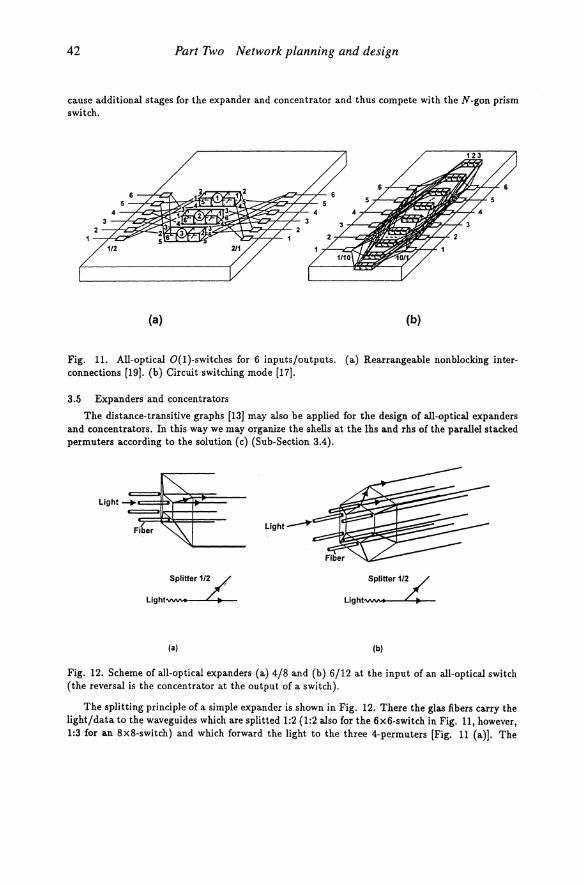
cause additional stages for the expander and concentrator and thus compete with the N-gon prism switch.
(a) (b)
Fig. 11. All-optical O(I)-switches for 6 inputs/outputs. (a) Rearrangeable nonblocking interconnections (19). (b) Circuit switching mode (17).
3.5 Expanders and concentrators
The distance-transitive graphs (13) may also be applied for the design of all-optical expanders and concentrators. In this way we may organize the shells at the lhs and rhs of the parallel stacked permuters according to the solution (c) (Sub-Section 3.4).
SPlitter1/~
LI9ht"WV' .... - .... 4-4-
(a)
Splitter 1/:./ Light-vw(V' ... - .... 4-4-
(b)
Fig. 12. Scheme of all-optical expanders (a) 4/8 and (b) 6/12 at the input of an all-optical switch (the reversal is the concentrator at the output of ~ switch).
The splitting principle of a simple expandeds shown in Fig. 12. There the glas fibers carry the light/data to the waveguides which are splitted 1:2 (1:2 also for the 6x6-switch in Fig. 11, however, 1:3 for an 8x8-switch) and which forward the light to the three 4-permuters [Fig. 11 (a)]. The
New directions in WDMIOFDM-networks 43
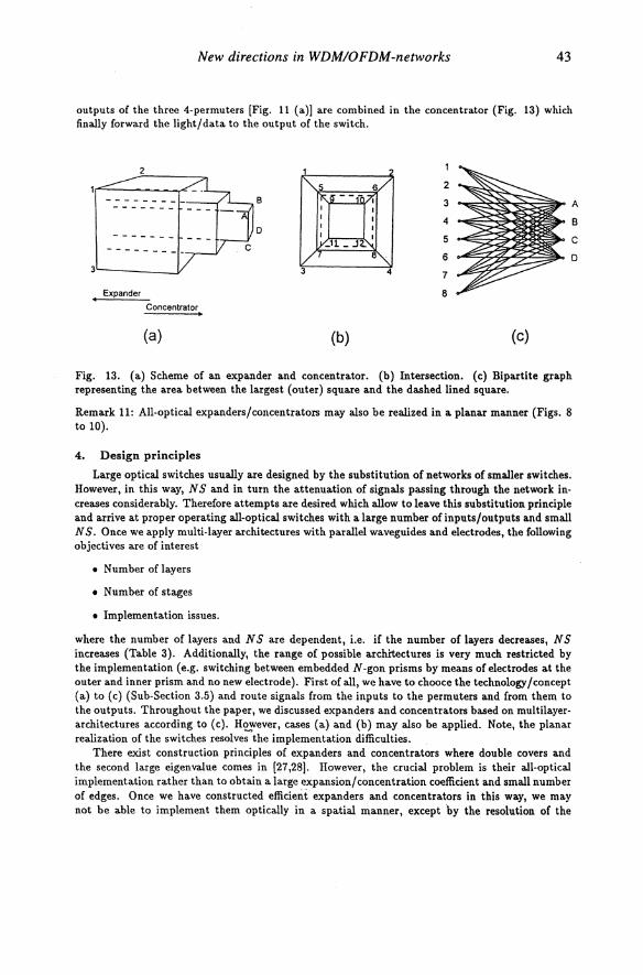
outputs of the three 4-permuters [Fig. 11 (a») are combined in the concentrator (Fig. 13) which finally forward the light/data to the output of the switch.
2
2
--------- B 3 A -------4 B
0 ------- 5 C
6 D 3
7
Expander 8 Concentrator • (a) (b) (c)
Fig. 13. (a) Scheme of an expander and concentrator. (b) Intersection. (c) Bipartite graph representing the area between the largest (outer) square and the dashed lined square.
Remark 11: All-optical expanders/concentrators may also be realized in a planar manner (Figs. 8 to 10).
4. Design principles
Large optical switches usually are designed by the substitution of networks of smaller switches. However, in this way, NS and in turn the attenuation of signals passing through the network increases considerably. Therefore attempts are desired which allow to leave this substitution principle and arrive at proper operating all-optical switches with a large number of inputs/outputs and small N S. Once we apply multi-layer architectures with parallel waveguides and electrodes, the following objectives are of interest
• Number of layers
• Number of stages
• Implementation issues.
where the number of layers and N S are dependent, i.e. if the number of layers decreases, N S increases (Table 3). Additionally, the range of possible architectures is very much restricted by the implementation (e.g. switching between embedded N -gon prisms by means of electrodes at the outer and inner prism and no new electrode). First of all, we have to chooce the technology/concept (a) to (c) (Sub-Section 3.5) and route signals from the inputs to the permuters and from them to the outputs. Throughout the paper, we discussed expanders and concentrators based on multilayerarchitectures according to (c). H~ever, cases (a) and (b) may also be applied. Note, the planar realization of the switches resolves the implementation difficulties.
There exist construction principles of expanders and concentrators where double covers and the second large eigenvalue comes in [27,28). However, the crucial problem is their all-optical implementation rather than to obtain a large expansion/concentration coefficient and small number of edges. Once we have constructed efficient expanders and concentrators in this way, we may not be able to implement them optically in a spatial manner, except "by the resolution of the
44 Part Two Network planning and design
interconnections via several stages. But in this case, we leave the O(l)-switch principle, i.e. NS will depend on the number of inputs/outputs.
:@: 4
(a) (b)
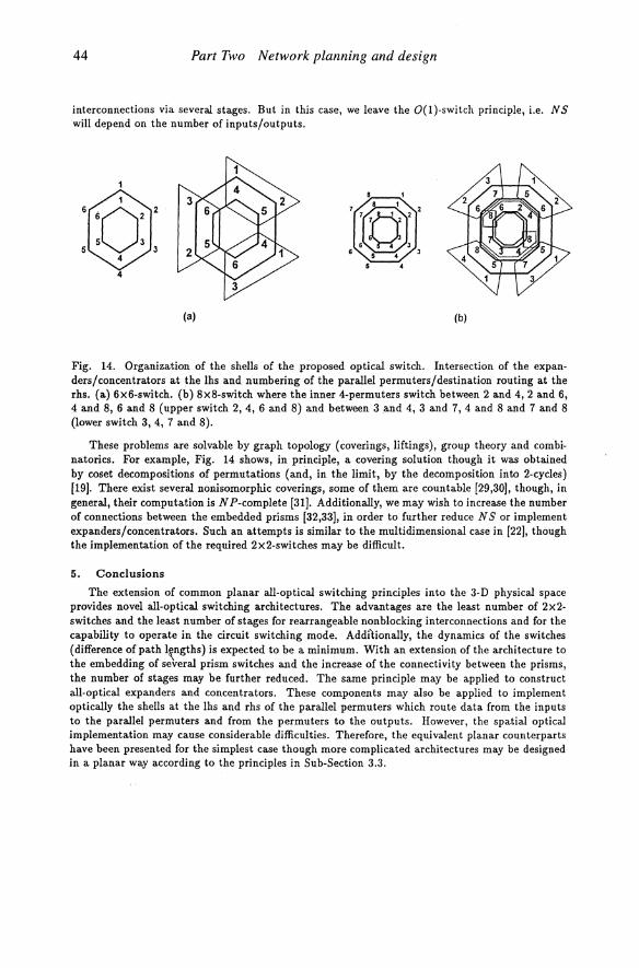
Fig. 14. Organization of the shells of the proposed optical switch. Intersection of the expanders/concentrators at the lhs and numbering of the parallel permuters/destination routing at the rhs. (a) 6x6-switch. (b) 8x8-switch where the inner 4-permuters switch between 2 and 4, 2 and 6, 4 and 8, 6 and 8 (upper switch 2, 4, 6 and 8) and between 3 and 4, 3 and 7,4 and 8 and 7 and 8 (lower switch 3, 4, 7 and 8).
These problems are solvable by graph topology (coverings, liftings), group theory and combinatorics. For example, Fig. 14 shows, in principle, a covering solution though it was obtained by coset decompositions of permutations (and, in the limit, by the decomposition into 2-cycles) [19]. There exist several nonisomorphic coverings, some of them are countable [29,30], though, in general, their computation is NP-complete [31]. Additionally, we may wish to increase the number of connections between the embedded prisms [32,33], in order to further reduce N S or implement expanders/concentrators. Such an attempts is similar to the multidimensional case in (22], though the implementation of the required 2x2-switches may be difficult.
5. Conclusions
The extension of common planar all-optical switching principles into the 3-D physical space provides novel all-optical switching architectures. The advantages are the least number of 2x2-switches and the least number of stages for rearrangeable non blocking interconnections and for the capability to operate in the circuit switching mode. Additionally, the dynamics of the switches (difference of path l~ngths) is expected to be a minimum. With an extension of the architecture to the embedding of several prism switches and the increase of the connectivity between the prisms, the number of stages may be further reduced. The same principle may be applied to construct all-optical expanders and concentrators. These components may also be applied to implement optically the shells at the lhs and rhs of the parallel permuters which route data from the inputs to the parallel permuters and from the permuters to the outputs. However, the spatial optical implementation may cause considerable difficulties. Therefore, the equivalent planar counterparts have been presented for the simplest case though more complicated architectures may be designed in a planar way according to the principles in Sub-Section 3.3.
New directions in WDMIOFDM-networks 45
Acknowledgement
The work is supported by the 'Bundesminister fUr Bildung, Wissenschaft, Forschung und Technologie' and the City of Berlin within the national PHOTONIK II program under contract 01 BP 449/2.
References
1. A. Ajmone Marsan, A. Bianco, E. Leonardi and F. Neri, 'De Bruijn topologies for self-routing all-optical networks,' SPIE, vol. 2024, pp.99-111, 1993.
2_ C. Berge, Graphs and Hypergraphs, North-Holland Publishing Company, 1973.
3_ S. Jiang and T. E. Stern, 'Regular multicast multihop lightwave networks,' INFOCOM'95, paper 63.3, pp.692-700, 1995.
4. W. S. Massey, Algebraic Topology: An Introduction, Springer, New York, 1977.
5. J. L. Gross and Th. W. Tucker, Topological Graph Theory, J. Wiley" New York, 1987.
6. F. Harary, J. P. Hayes and H.-J. Wu, 'A survey of the theory of hypercube graphs,' Comput. Math. Appl., vol. 15, no. 4, pp.277-289, 1988.
7. D. A. Waller, 'Double covers of graphs,' Bull. Austral. Math. Soc., vol. 14, pp.233-248, 1976.
8. D. Angluin and A. Gardiner, 'Finite common coverings of palrs of regular graphs,' J. Combin. Theory, vol. B-30, pp.184-187, 1981.
9. J. R. Munkres, Topology, a 1st course, Prentic Hall, Englewood Cliffs, 1975.
10. W. Kautz, K. N. Levitt and A. Waksman, 'Cellular interconnection arrays,' IEEE Trans. Comput., vol. C-17, no. 5, pp.162-170, May 1968.
11. HHI, Optical Switch Routing Subroutine Library, 1996.
12. D. Z. Djokovic, 'Automorphism of graphs and coverings,' J. Combin. Theory, vol. B-16, pp.243-247,1974.
13. N. Biggs, Algebraic Graph Theory, Cambridge University Press, 1974.
14. R. M. Tanner, 'Explicit concentrators from generalized N-gons,' Siam J. Aig. Disc. Meth., vol. is, no. 3, pp.287-293, September 1984.
15. M. Farzan and D. A. Waller, 'Antipodal embeddings of graphs,' J. London Math. Soc., vol. 15-2, pp.377 -383, 1977.
16. R. A. Spanke and V. E. Benes, 'N-stage planar optical permutation network,' Appl. Opt., vol. 26, no. 7, pp.1226-1229, 1987.
17. J. Giglmayr, 'Novel all-optical planar and compact minimum-stage switches of size ;?:4x4,' SPIE 2918, pp.240-258, 1996.
18. J. Giglmayr, 'Principles of all-optical switching fabrics with minimum number of stages,' Spring Topical Meeting Optics in Computing, Hyatt Lake Tahoe, Incline Village, Nevada, USA, 17-21 March, 1997.
46 Part Two Network planning and design
19. J. Giglmayr, 'Reduction of parallelism in optical O(I}-switches,' Conference on Information Sciences and Systems, Johns Hopkins University, Baltimore, 19-21 March, 1991.
20. T. Pisanski, J. Shawe-Taylor and J_ Vrabec, 'Edge-colorability of graph bundles,' J. Combin. Theory, vol. B-35, pp.12-19, 1983.
21. A. Graham, Kronecker Products and Matri:r: Calculus with Applications, E. Horwood, 1981.
22. J. Giglmayr, 'Rearrangeability and connectivity of multistage interconnection networks with nearest-neighbour interconnections,' IEICE Trans. Commun. (Japan), vol. E77-B, no.12, pp.1546-1555, December 1994.
23. A. Blass, F. Hararyand Z. Miller, 'Which trees are link graphs,' J. Combin. Theory, vol. B-29, pp.271-292, 1980.
24. J. Giglmayr, 'Kautz topologies for all-optical self-routing networks,' SPIE 2614, pp.168-182, 1995.
25. G. E. Carison, J. E. Cruthirds, H. B. Sexton and C. G. Wright, 'Interconnection networks based on a generalization of cube-connected cycles,' IEEE Trans. Comput., vol. C-34, no. 8, pp.169-772, August 1985.
26. A. Y. Oruc, 'Designing cellular permutation networks through coset decompositions of symmetric groups,' J. Para.1lel and Distributed Computing, vol. 4, pp.404-422, 1981.
27. G. A. Margulis, 'Explicit constructions of concentrators,' Problemy Pereda.chi Informatsii, vol. 9, no. 4, pp.71-80, 1913.
28. O. Gabber and Z. Gali1, 'Explicit constructions of linear-sized superconcentrators,' J. Computer and System Science, vol. 22, pp.401-422, 1981.
29. M. Hofmeister, 'Counting double covers of graphs,' J. Graph Theory, vol. 12, no. 3, pp.431-444, 1988.
30. S. Hong and J. H. Kwak, 'Regular fourfold coverings with respect to the identity automorphism,' J. Graph Theory, vol. 11, no. 5, pp.621-621, 1993.
31. VEGA, Graph Gallery, version 0.2, University of Ljubljana, 1995.
32. M. Farzan and D. A. Wa.1\er, 'Kronecker products and local joins of graphs,' Can. J. Math., vol. 24, no. 2, pp.255-269, 1977.
33. N. Hartsfield and G. Ringel, Pearls in Graph Theory, Academic Press, 1994.