networkmodels - abcd.lkabcd.lk/sliit/ebooks/data communications and networking/chapter … · 32...
TRANSCRIPT

CHAPTER 2
Network Models
A network is a combination of hardware and software that sends data from one locationto another. The hardware consists of the physical equipment that carries signals fromone point of the network to another. The software consists of instruction sets that makepossible the services that we expect from a network.
We can compare the task of networking to the task of solving a mathematics problemwith a computer. The fundamental job of solving the problem with a computer is doneby computer hardware. However, this is a very tedious task if only hardware is involved.We would need switches for every memory location to store and manipulate data. Thetask is much easier if software is available. At the highest level, a program can directthe problem-solving process; the details of how this is done by the actual hardware canbe left to the layers of software that are called by the higher levels.
Compare this to a service provided by a computer network. For example, the taskof sending an e-mail from one point in the world to another can be broken into severaltasks, each performed by a separate software package. Each software package uses theservices of another software package. At the lowest layer, a signal, or a set of signals, issent from the source computer to the destination computer.
In this chapter, we give a general idea of the layers of a network and discuss thefunctions of each. Detailed descriptions of these layers follow in later chapters.
2.1 LAYERED TASKSWe use the concept of layers in our daily life. As an example, let us consider twofriends who communicate through postal maiL The process of sending a letter to afriend would be complex if there were no services available from the post office. Figure 2.1 shows the steps in this task.
27

28 CHAPTER 2 NETWORK MODELS
Figure 2.1 Tasks involved in sending a letter
Sender
tReceiver
tI t
The letter is written, The letter is picked up,put in an envelope, and Higher layers removed from thedropped in a mailbox. envelope, and read.
I -,The letter is carried The letter is carriedfrom the mailbox Middle layers from the post officeto a post office. to the mailbox.
I IThe letter is delivered The letter is deliveredto a carrier by the post Lower layers from the carrier
office. to the post office.
• II
The parcel is carried fromthe source to the destination.
Sender, Receiver, and CarrierIn Figure 2.1 we have a sender, a receiver, and a carrier that transports the letter. Thereis a hierarchy of tasks.
At the Sellder Site
Let us first describe, in order, the activities that take place at the sender site.
o Higher layer. The sender writes the letter, inserts the letter in an envelope, writesthe sender and receiver addresses, and drops the letter in a mailbox.
o Middle layer. The letter is picked up by a letter carrier and delivered to the postoffice.
o Lower layer. The letter is sorted at the post office; a carrier transports the letter.
011 the Way
The letter is then on its way to the recipient. On the way to the recipient's local postoffice, the letter may actually go through a central office. In addition, it may be transported by truck, train, airplane, boat, or a combination of these.
At the Receiver Site
o Lower layer. The carrier transports the letter to the post office.
o Middle layer. The letter is sorted and delivered to the recipient's mailbox.
o Higher layer. The receiver picks up the letter, opens the envelope, and reads it.

SECTION 2.2 THE OS! MODEL 29
Hierarchy
According to our analysis, there are three different activities at the sender site andanother three activities at the receiver site. The task of transporting the letter betweenthe sender and the receiver is done by the carrier. Something that is not obviousimmediately is that the tasks must be done in the order given in the hierarchy. At thesender site, the letter must be written and dropped in the mailbox before being pickedup by the letter carrier and delivered to the post office. At the receiver site, the lettermust be dropped in the recipient mailbox before being picked up and read by therecipient.
Services
Each layer at the sending site uses the services of the layer immediately below it. Thesender at the higher layer uses the services of the middle layer. The middle layer usesthe services of the lower layer. The lower layer uses the services of the carrier.
The layered model that dominated data communications and networking literaturebefore 1990 was the Open Systems Interconnection (OSI) model. Everyone believedthat the OSI model would become the ultimate standard for data communications, butthis did not happen. The TCPIIP protocol suite became the dominant commercial architecture because it was used and tested extensively in the Internet; the OSI model wasnever fully implemented.
In this chapter, first we briefly discuss the OSI model, and then we concentrate onTCPIIP as a protocol suite.
2.2 THE OSI MODELEstablished in 1947, the International Standards Organization (ISO) is a multinationalbody dedicated to worldwide agreement on international standards. An ISO standardthat covers all aspects of network communications is the Open Systems Interconnectionmodel. It was first introduced in the late 1970s. An open system is a set of protocols thatallows any two different systems to communicate regardless of their underlying architecture. The purpose of the OSI model is to show how to facilitate communicationbetween different systems without requiring changes to the logic of the underlying hardware and software. The OSI model is not a protocol; it is a model for understanding anddesigning a network architecture that is flexible, robust, and interoperable.
ISO is the organization. OSI is the model.
The OSI model is a layered framework for the design of network systems thatallows communication between all types of computer systems. It consists of seven separate but related layers, each of which defines a part of the process of moving informationacross a network (see Figure 2.2). An understanding of the fundamentals of the OSImodel provides a solid basis for exploring data communications.

30 CHAPTER 2 NETWORK MODELS
Figure 2.2 Seven layers of the OSI model
71 Application
61 Presentation
51 Session
41 Transport
31 Network
21 Data link
1 I Physical
Layered ArchitectureThe OSI model is composed of seven ordered layers: physical (layer 1), data link (layer 2),network (layer 3), transport (layer 4), session (layer 5), presentation (layer 6), andapplication (layer 7). Figure 2.3 shows the layers involved when a message is sent fromdevice A to device B. As the message travels from A to B, it may pass through manyintermediate nodes. These intermediate nodes usually involve only the first three layersof the OSI model.
In developing the model, the designers distilled the process of transmitting data toits most fundamental elements. They identified which networking functions had relateduses and collected those functions into discrete groups that became the layers. Eachlayer defines a family of functions distinct from those of the other layers. By definingand localizing functionality in this fashion, the designers created an architecture that isboth comprehensive and flexible. Most importantly, the OSI model allows completeinteroperability between otherwise incompatible systems.
Within a single machine, each layer calls upon the services of the layer just belowit. Layer 3, for example, uses the services provided by layer 2 and provides services forlayer 4. Between machines, layer x on one machine communicates with layer x onanother machine. This communication is governed by an agreed-upon series of rulesand conventions called protocols. The processes on each machine that communicate ata given layer are called peer-to-peer processes. Communication between machines istherefore a peer-to-peer process using the protocols appropriate to a given layer.
Peer-to-Peer Processes
At the physical layer, communication is direct: In Figure 2.3, device A sends a streamof bits to device B (through intermediate nodes). At the higher layers, however, communication must move down through the layers on device A, over to device B, and then

SECTION 2.2 THE OSI MODEL 31
Figure 2.3 The interaction between layers in the OSI model
DeviceA
DeviceB
Intermediatenode
Intermediatenode
Peer-to-peer protocol Oth layer)7 Application ------------------------ Application 7
7-6 interface 7-6 interfacePeer-to-peer protocol (6th layer)
6 Presentation ------------------------ Presentation 6
6-5 interface 6-5 interfacePeer-to-peer protocol (5th layer)
5 Session ------------------------ Session 5
5-4 interfacePeer-to-peer protocol (4th layer)
5-4 interface
4 Transport ------------------------ Transport 4
4-3 interface 4-3 interface
3 Network Network 3
3-2 interface 3-2 interface
2 Data link Data link 2
2-1 interface 2-1 interface
Physical Physical
Physical communication
back up through the layers. Each layer in the sending device adds its own informationto the message it receives from the layer just above it and passes the whole package tothe layer just below it.
At layer I the entire package is converted to a form that can be transmitted to thereceiving device. At the receiving machine, the message is unwrapped layer by layer,with each process receiving and removing the data meant for it. For example, layer 2removes the data meant for it, then passes the rest to layer 3. Layer 3 then removes thedata meant for it and passes the rest to layer 4, and so on.
Interfaces Between Layers
The passing of the data and network information down through the layers of the sending device and back up through the layers of the receiving device is made possible byan interface between each pair of adjacent layers. Each interface defines the information and services a layer must provide for the layer above it. Well-defined interfaces andlayer functions provide modularity to a network. As long as a layer provides theexpected services to the layer above it, the specific implementation of its functions canbe modified or replaced without requiring changes to the surrounding layers.
Organization of the Layers
The seven layers can be thought of as belonging to three subgroups. Layers I, 2, and3-physical, data link, and network-are the network support layers; they deal with

32 CHAPTER 2 NETWORK MODELS
the physical aspects of moving data from one device to another (such as electricalspecifications, physical connections, physical addressing, and transport timing andreliability). Layers 5, 6, and 7-session, presentation, and application-can bethought of as the user support layers; they allow interoperability among unrelatedsoftware systems. Layer 4, the transport layer, links the two subgroups and ensuresthat what the lower layers have transmitted is in a form that the upper layers can use.The upper OSI layers are almost always implemented in software; lower layers are acombination of hardware and software, except for the physical layer, which is mostlyhardware.
In Figure 2.4, which gives an overall view of the OSI layers, D7 means the dataunit at layer 7, D6 means the data unit at layer 6, and so on. The process starts at layer7 (the application layer), then moves from layer to layer in descending, sequentialorder. At each layer, a header, or possibly a trailer, can be added to the data unit.Commonly, the trailer is added only at layer 2. When the formatted data unit passesthrough the physical layer (layer 1), it is changed into an electromagnetic signal andtransported along a physical link.
Figure 2.4 An exchange using the OS! model
:HiiD7lt---~
~~§J D6 I:Hs-1 D5 Ir- _J
:H4j D4 Ir--- .------
:-Hi l D3 Ir-- J---=-=----
:HiJ D2 ~.j!1- - - .10--1
:_~i§j 010101010101101010000010000 I
Trn",m;"io" =dium 1
~~ D6 I~ D5 I
~ D4 I~ D3 I~ D2 •
@IQj 010101010101101010000010000 I
L...Upon reaching its destination, the signal passes into layer 1 and is transformed
back into digital form. The data units then move back up through the OSI layers. Aseach block of data reaches the next higher layer, the headers and trailers attached to it atthe corresponding sending layer are removed, and actions appropriate to that layer aretaken. By the time it reaches layer 7, the message is again in a form appropriate to theapplication and is made available to the recipient.

SECTION 2.3 LAYERS IN THE OSI MODEL 33
Encapsulation
Figure 2.3 reveals another aspect of data communications in the OSI model: encapsulation. A packet (header and data) at level 7 is encapsulated in a packet at level 6. Thewhole packet at level 6 is encapsulated in a packet at level 5, and so on.
In other words, the data portion of a packet at level N - 1 carries the whole packet(data and header and maybe trailer) from level N. The concept is called encapsulation;level N - 1 is not aware of which part of the encapsulated packet is data and which partis the header or trailer. For level N - 1, the whole packet coming from level N is treatedas one integral unit.
2.3 LAYERS IN THE OSI MODELIn this section we briefly describe the functions of each layer in the OSI model.
Physical Layer
The physical layer coordinates the functions required to carry a bit stream over a physical medium. It deals with the mechanical and electrical specifications of the interface andtransmission medium. It also defines the procedures and functions that physical devicesand interfaces have to perform for transmission to Occur. Figure 2.5 shows the position ofthe physical layer with respect to the transmission medium and the data link layer.
Figure 2.5 Physical layer
From data link layer To data link layer
Physicallayer
Physicallayer
Transmission medium
The physical layer is responsible for movements ofindividual bits from one hop (node) to the next.
The physical layer is also concerned with the following:
o Physical characteristics of interfaces and medium. The physical layer definesthe characteristics of the interface between the devices and the transmissionmedium. It also defines the type of transmission medium.
o Representation of bits. The physical layer data consists of a stream of bits(sequence of Os or 1s) with no interpretation. To be transmitted, bits must be
34 CHAPTER 2 NETWORK MODELS
encoded into signals--electrical or optical. The physical layer defines the type ofencoding (how Os and Is are changed to signals).
o Data rate. The transmission rate-the number of bits sent each second-is alsodefined by the physical layer. In other words, the physical layer defines the duration of a bit, which is how long it lasts.
o Synchronization of bits. The sender and receiver not only must use the same bitrate but also must be synchronized at the bit level. In other words, the sender andthe receiver clocks must be synchronized.
o Line configuration. The physical layer is concerned with the connection ofdevices to the media. In a point-to-point configuration, two devices are connectedthrough a dedicated link. In a multipoint configuration, a link is shared amongseveral devices.
o Physical topology. The physical topology defines how devices are connected tomake a network. Devices can be connected by using a mesh topology (every deviceis connected to every other device), a star topology (devices are connected througha central device), a ring topology (each device is connected to the next, forming aring), a bus topology (every device is on a common link), or a hybrid topology (thisis a combination of two or more topologies).
o Transmission mode. The physical layer also defines the direction of transmissionbetween two devices: simplex, half-duplex, or full-duplex. In simplex mode, onlyone device can send; the other can only receive. The simplex mode is a one-waycommunication. In the half-duplex mode, two devices can send and receive, butnot at the same time. In a full-duplex (or simply duplex) mode, two devices cansend and receive at the same time.
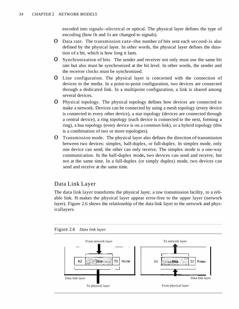
Data Link LayerThe data link layer transforms the physical layer, a raw transmission facility, to a reliable link. It makes the physical layer appear error-free to the upper layer (networklayer). Figure 2.6 shows the relationship of the data link layer to the network and physicallayers.
Figure 2.6 Data link layer
From network layer
Data link layer
To physical layer
H2
To network layer
Data link layer
From physical layer
SECTION 2.3 LAYERS IN THE OSI MODEL 35
The data link layer is responsible for moving frames from one hop (node) to the next.
Other responsibilities of the data link layer include the following:
[I Framing. The data link layer divides the stream of bits received from the networklayer into manageable data units called frames.
o Physical addressing. If frames are to be distributed to different systems on thenetwork, the data link layer adds a header to the frame to define the sender and/orreceiver of the frame. If the frame is intended for a system outside the sender'snetwork, the receiver address is the address of the device that connects the networkto the next one.
D Flow control. If the rate at which the data are absorbed by the receiver is less thanthe rate at which data are produced in the sender, the data link layer imposes a flowcontrol mechanism to avoid overwhelming the receiver.
o Error control. The data link layer adds reliability to the physical layer by addingmechanisms to detect and retransmit damaged or lost frames. It also uses a mechanism to recognize duplicate frames. Error control is normally achieved through atrailer added to the end of the frame.
D Access control. When two or more devices are connected to the same link, datalink layer protocols are necessary to determine which device has control over thelink at any given time.
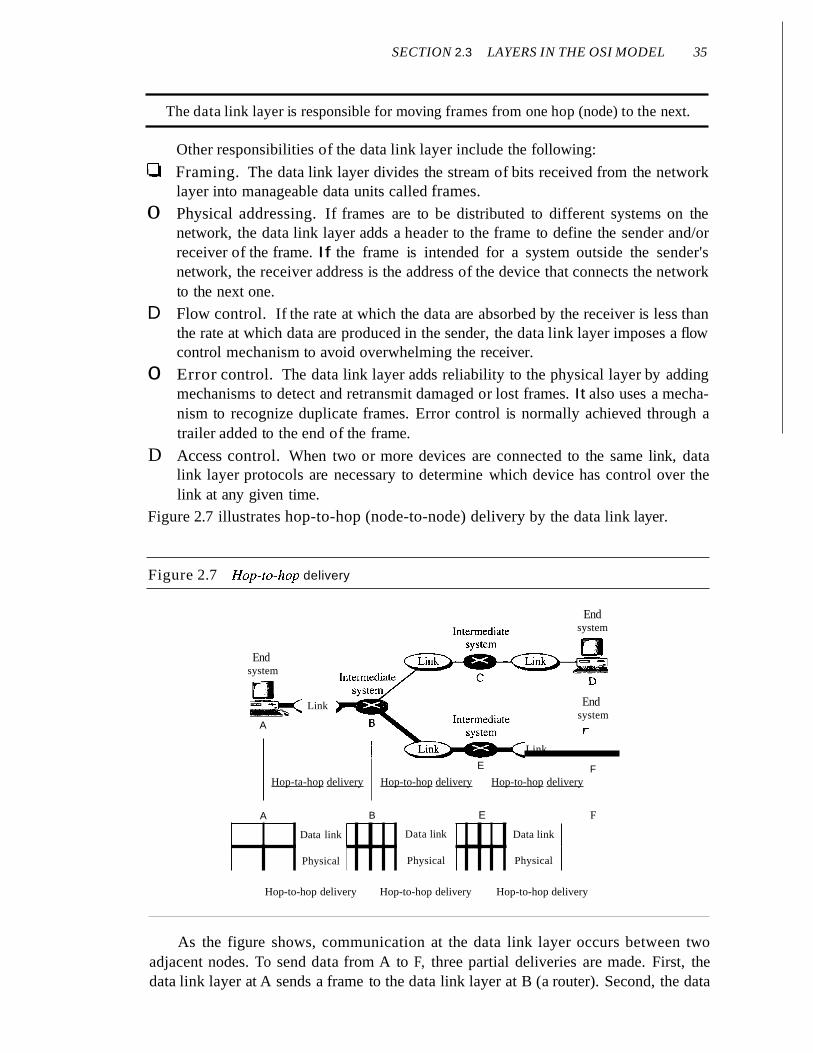
Figure 2.7 illustrates hop-to-hop (node-to-node) delivery by the data link layer.
Figure 2.7 Hop-fa-hop delivery
Endsystem
r
Link
Link
A
Endsystem
r
Endsystem
E FHop-ta-hop delivery Hop-to-hop delivery Hop-to-hop delivery
A B E F
Data link Data link Data link
Physical Physical Physical
Hop-to-hop delivery Hop-to-hop delivery Hop-to-hop delivery
As the figure shows, communication at the data link layer occurs between twoadjacent nodes. To send data from A to F, three partial deliveries are made. First, thedata link layer at A sends a frame to the data link layer at B (a router). Second, the data

36 CHAPTER 2 NETWORK MODELS
link layer at B sends a new frame to the data link layer at E. Finally, the data link layerat E sends a new frame to the data link layer at F. Note that the frames that areexchanged between the three nodes have different values in the headers. The frame fromA to B has B as the destination address and A as the source address. The frame from B toE has E as the destination address and B as the source address. The frame from E to Fhas F as the destination address and E as the source address. The values of the trailerscan also be different if error checking includes the header of the frame.
Network LayerThe network layer is responsible for the source-to-destination delivery of a packet,possibly across multiple networks (links). Whereas the data link layer oversees thedelivery of the packet between two systems on the same network (links), the networklayer ensures that each packet gets from its point of origin to its final destination.
If two systems are connected to the same link, there is usually no need for a network layer. However, if the two systems are attached to different networks (links) withconnecting devices between the networks (links), there is often a need for the networklayer to accomplish source-to-destination delivery. Figure 2.8 shows the relationship ofthe network layer to the data link and transport layers.
Figure 2.8 Network layer
From transport layer
I
1 -,,-_1
~: Data .1 Packet
I I
To transport layer...I
',,- - -H-3- - _]1...jI. Data,. Packeti------'-----'-------1
Networklayer ...,
To data link layer
Networklayer
From data link layer
The network layer is responsible for the delivery of individualpackets from the source host to the destination host.
Other responsibilities of the network layer include the following:
o Logical addressing. The physical addressing implemented by the data link layerhandles the addressing problem locally. If a packet passes the network boundary,we need another addressing system to help distinguish the source and destinationsystems. The network layer adds a header to the packet coming from the upperlayer that, among other things, includes the logical addresses of the sender andreceiver. We discuss logical addresses later in this chapter.
o Routing. When independent networks or links are connected to create intemetworks(network of networks) or a large network, the connecting devices (called routers

SECTION 2.3 LAYERS IN THE OSI MODEL 37
or switches) route or switch the packets to their final destination. One of the functions of the network layer is to provide this mechanism.
Figure 2.9 illustrates end-to-end delivery by the network layer.
Figure 2.9 Source-to-destination delivery
Endsystem
r
Link
Intermediatesystem
A
Endsystem
r
Endsystem
r
E FHOP-lO-hop delivery Hop-to-hop delivery HOp-lO-hop delivery
Source-to-destination delivery
A B E F
Network - Network - Network
Data link Data link Data link
Physical Physical Physical
I. Source-to-destination delivery ,I
As the figure shows, now we need a source-to-destination delivery. The network layerat A sends the packet to the network layer at B. When the packet arrives at router B, therouter makes a decision based on the final destination (F) of the packet. As we will seein later chapters, router B uses its routing table to find that the next hop is router E. Thenetwork layer at B, therefore, sends the packet to the network layer at E. The networklayer at E, in tum, sends the packet to the network layer at F.
Transport LayerThe transport layer is responsible for process-to-process delivery of the entire message. A process is an application program running on a host. Whereas the network layeroversees source-to-destination delivery of individual packets, it does not recognizeany relationship between those packets. It treats each one independently, as thougheach piece belonged to a separate message, whether or not it does. The transport layer,on the other hand, ensures that the whole message arrives intact and in order, overseeingboth error control and flow control at the source-to-destination level. Figure 2.10 showsthe relationship of the transport layer to the network and session layers.

38 CHAPTER 2 NETWORK MODELS
Figure 2.10 Transport layer
From session layer To session layer
\\\\
Transportlayer
Segments
From network layer
//
CH!lData II I
To network layer
/ / I I \ \
IH4 (Data rIH4 f Data rIH4) Data 1I I I I I I
Segments
Transportlayer
The transport layer is responsible for the delivery of a message from one process to another.
Other responsibilities of the transport layer include the following:
o Service-point addressing. Computers often run several programs at the sametime. For this reason, source-to-destination delivery means delivery not only fromone computer to the next but also from a specific process (running program) onone computer to a specific process (running program) on the other. The transportlayer header must therefore include a type of address called a service-pointaddress (or port address). The network layer gets each packet to the correctcomputer; the transport layer gets the entire message to the correct process onthat computer.
o Segmentation and reassembly. A message is divided into transmittable segments,with each segment containing a sequence number. These numbers enable the transport layer to reassemble the message correctly upon arriving at the destination andto identify and replace packets that were lost in transmission.
o Connection control. The transport layer can be either connectionless or connectionoriented. A connectionless transport layer treats each segment as an independentpacket and delivers it to the transport layer at the destination machine. A connectionoriented transport layer makes a connection with the transport layer at the destination machine first before delivering the packets. After all the data are transferred,the connection is terminated.
o Flow control. Like the data link layer, the transport layer is responsible for flowcontrol. However, flow control at this layer is performed end to end rather thanacross a single link.
o Error control. Like the data link layer, the transport layer is responsible forerror control. However, error control at this layer is performed process-toprocess rather than across a single link. The sending transport layer makes surethat the entire message arrives at the receiving transport layer without error(damage, loss, or duplication). Error correction is usually achieved throughretransmission.
SECTION 2.3 LAYERS IN THE OSI MODEL 39
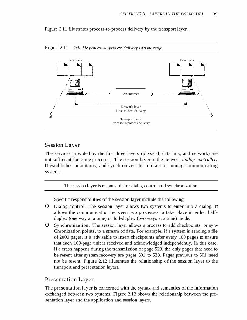
Figure 2.11 illustrates process-to-process delivery by the transport layer.
Figure 2.11 Reliable process-to-process delivery ofa message
Processes Processes
\\
\\
\\
)-----~~~~'C)\\\
\\
\\
\\
~
An internet
II
I,,,,/ ~~~~,....-----<
, I I/ I I
, I-.I.----------------------.J.I/ I Network layer I
, Host-to-host delivery
LTransport layer
Process-to-process delivery
Session Layer
The services provided by the first three layers (physical, data link, and network) arenot sufficient for some processes. The session layer is the network dialog controller.It establishes, maintains, and synchronizes the interaction among communicatingsystems.
The session layer is responsible for dialog control and synchronization.
Specific responsibilities of the session layer include the following:
o Dialog control. The session layer allows two systems to enter into a dialog. Itallows the communication between two processes to take place in either halfduplex (one way at a time) or full-duplex (two ways at a time) mode.
o Synchronization. The session layer allows a process to add checkpoints, or synChronization points, to a stream of data. For example, if a system is sending a fileof 2000 pages, it is advisable to insert checkpoints after every 100 pages to ensurethat each 100-page unit is received and acknowledged independently. In this case,if a crash happens during the transmission of page 523, the only pages that need tobe resent after system recovery are pages 501 to 523. Pages previous to 501 neednot be resent. Figure 2.12 illustrates the relationship of the session layer to thetransport and presentation layers.
Presentation Layer
The presentation layer is concerned with the syntax and semantics of the informationexchanged between two systems. Figure 2.13 shows the relationship between the presentation layer and the application and session layers.

40 CHAPTER 2 NETWORK MODELS
Figure 2.12 Session layer
I III
1/ I I II I I I I
• , I
I~')~:{~~ ,
r' ~"''' 9 ~,
Isyn syn syn
I
To presentation layer
~i1-,I
I
II
I
I
II
I
From presentation layer
1I
/ ;f t/ I~ II
~.•. lsyn syn syn
1
Sessionlayer
Sessionlayer
To transport layer From transport layer
Figure 2.13 Presentation layer
From application layer
ITo application layer..
I;.......,.1 --1
~l ...,i "J)8,tfi~~. ,.JI I
Presentationlayer
...
To session layer
Presentationlayer
From session layer
The presentation layer is responsible for translation, compression, and encryption.
Specific responsibilities of the presentation layer include the following:
o Translation. The processes (running programs) in two systems are usually exchanging information in the form of character strings, numbers, and so on. The infonnation must be changed to bit streams before being transmitted. Because differentcomputers use different encoding systems, the presentation layer is responsible forinteroperability between these different encoding methods. The presentation layerat the sender changes the information from its sender-dependent format into acommon format. The presentation layer at the receiving machine changes thecommon format into its receiver-dependent format.
o Encryption. To carry sensitive information, a system must be able to ensureprivacy. Encryption means that the sender transforms the original information to
SECTION 2.3 LAYERS IN THE OSI MODEL 41
another form and sends the resulting message out over the network. Decryptionreverses the original process to transform the message back to its original form.
o Compression. Data compression reduces the number of bits contained in theinformation. Data compression becomes particularly important in the transmissionof multimedia such as text, audio, and video.
Application Layer
The application layer enables the user, whether human or software, to access the network. It provides user interfaces and support for services such as electronic mail,remote file access and transfer, shared database management, and other types of distributed information services.
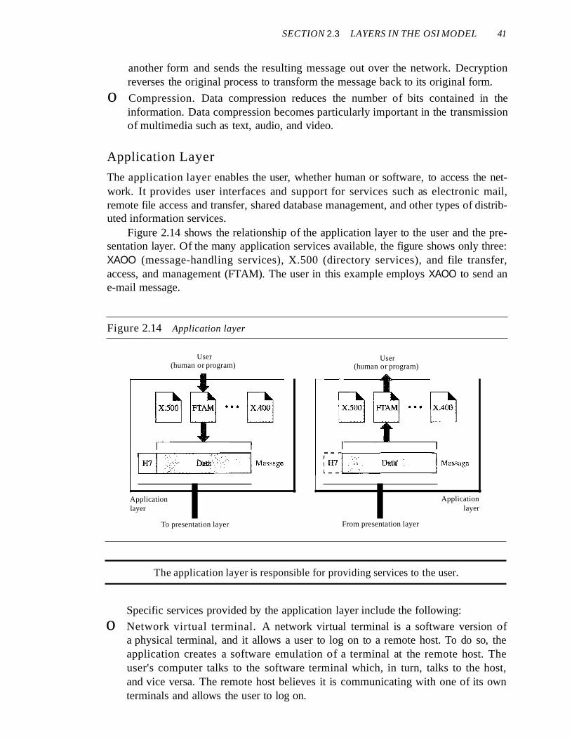
Figure 2.14 shows the relationship of the application layer to the user and the presentation layer. Of the many application services available, the figure shows only three:XAOO (message-handling services), X.500 (directory services), and file transfer,access, and management (FTAM). The user in this example employs XAOO to send ane-mail message.
Figure 2.14 Application layer
Data' ~:.
User(human or program)
Applicationlayer
To presentation layer
User(human or program)
Applicationlayer
From presentation layer
The application layer is responsible for providing services to the user.
Specific services provided by the application layer include the following:
o Network virtual terminal. A network virtual terminal is a software version ofa physical terminal, and it allows a user to log on to a remote host. To do so, theapplication creates a software emulation of a terminal at the remote host. Theuser's computer talks to the software terminal which, in turn, talks to the host,and vice versa. The remote host believes it is communicating with one of its ownterminals and allows the user to log on.

42 CHAPTER 2 NETWORK MODELS
o File transfer, access, and management. This application allows a user to accessfiles in a remote host (to make changes or read data), to retrieve files from a remotecomputer for use in the local computer, and to manage or control files in a remotecomputer locally.
o Mail services. This application provides the basis for e-mail forwarding andstorage.
o Directory services. This application provides distributed database sources andaccess for global information about various objects and services.
Summary of Layers
Figure 2.15 shows a summary of duties for each layer.
Figure 2.15 Summary of layers
To translate, encrypt, andcompress data
To provide reliable process-toprocess message delivery anderror recovery
To organize bits into frames;to provide hop-to-hop delivery
Application
Presentation
Session
Transport
Network
Data link
Physical
To allow access to networkresources
To establish, manage, andterminate sessions
To move packets from sourceto destination; to provideinternetworking
To transmit bits over a medium;to provide mechanical andelectrical specifications
2.4 TCP/IP PROTOCOL SUITEThe TCPIIP protocol suite was developed prior to the OSI model. Therefore, the layers in the TCP/IP protocol suite do not exactly match those in the OSI model. Theoriginal TCP/IP protocol suite was defined as having four layers: host-to-network,internet, transport, and application. However, when TCP/IP is compared to OSI, we cansay that the host-to-network layer is equivalent to the combination of the physical anddata link layers. The internet layer is equivalent to the network layer, and the application layer is roughly doing the job of the session, presentation, and application layerswith the transport layer in TCPIIP taking care of part of the duties of the session layer.So in this book, we assume that the TCPIIP protocol suite is made of five layers: physical, data link, network, transport, and application. The first four layers provide physicalstandards, network interfaces, internetworking, and transport functions that correspondto the first four layers of the OSI model. The three topmost layers in the OSI model,however, are represented in TCPIIP by a single layer called the application layer (seeFigure 2.16).
SECTION 2.4 TCPIIP PROTOCOL SUITE 43
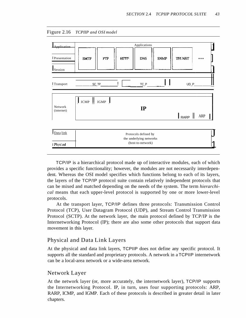
Figure 2.16 TCPIIP and OSI model
IApplication Applications J
8GB8GBI Presentation ... ]ISession 1I Transport ___SC_TP__! IL-.-__TC_P__I I UD_P__II
I ICMP II IGMP INetwork IP(internet)
I RARP II ARP I
IData link
I Physical
Protocols defined bythe underlying networks
(host-to-network)
J1
TCP/IP is a hierarchical protocol made up of interactive modules, each of whichprovides a specific functionality; however, the modules are not necessarily interdependent. Whereas the OSI model specifies which functions belong to each of its layers,the layers of the TCP/IP protocol suite contain relatively independent protocols thatcan be mixed and matched depending on the needs of the system. The term hierarchical means that each upper-level protocol is supported by one or more lower-levelprotocols.
At the transport layer, TCP/IP defines three protocols: Transmission ControlProtocol (TCP), User Datagram Protocol (UDP), and Stream Control TransmissionProtocol (SCTP). At the network layer, the main protocol defined by TCP/IP is theInternetworking Protocol (IP); there are also some other protocols that support datamovement in this layer.
Physical and Data Link Layers
At the physical and data link layers, TCPIIP does not define any specific protocol. Itsupports all the standard and proprietary protocols. A network in a TCPIIP internetworkcan be a local-area network or a wide-area network.
Network Layer
At the network layer (or, more accurately, the internetwork layer), TCP/IP supportsthe Internetworking Protocol. IP, in turn, uses four supporting protocols: ARP,RARP, ICMP, and IGMP. Each of these protocols is described in greater detail in laterchapters.

44 CHAPTER 2 NETWORK MODELS
Internetworking Protocol (IP)
The Internetworking Protocol (IP) is the transmission mechanism used by the TCP/IPprotocols. It is an unreliable and connectionless protocol-a best-effort delivery service.The term best effort means that IP provides no error checking or tracking. IP assumesthe unreliability of the underlying layers and does its best to get a transmission throughto its destination, but with no guarantees.
IP transports data in packets called datagrams, each of which is transported separately. Datagrams can travel along different routes and can arrive out of sequence or beduplicated. IP does not keep track of the routes and has no facility for reordering datagrams once they arrive at their destination.
The limited functionality of IP should not be considered a weakness, however. IPprovides bare-bones transmission functions that free the user to add only those facilitiesnecessary for a given application and thereby allows for maximum efficiency. IP is discussed in Chapter 20.
Address Resolution Protocol
The Address Resolution Protocol (ARP) is used to associate a logical address with aphysical address. On a typical physical network, such as a LAN, each device on a linkis identified by a physical or station address, usually imprinted on the network interfacecard (NIC). ARP is used to find the physical address of the node when its Internetaddress is known. ARP is discussed in Chapter 21.
Reverse Address Resolution Protocol
The Reverse Address Resolution Protocol (RARP) allows a host to discover its Internet address when it knows only its physical address. It is used when a computer is connected to a network for the first time or when a diskless computer is booted. We discussRARP in Chapter 21.
Internet Control Message Protocol
The Internet Control Message Protocol (ICMP) is a mechanism used by hosts andgateways to send notification of datagram problems back to the sender. ICMP sendsquery and error reporting messages. We discuss ICMP in Chapter 21.
Internet Group Message Protocol
The Internet Group Message Protocol (IGMP) is used to facilitate the simultaneoustransmission of a message to a group of recipients. We discuss IGMP in Chapter 22.
Transport LayerTraditionally the transport layer was represented in TCP/IP by two protocols: TCP andUDP. IP is a host-to-host protocol, meaning that it can deliver a packet from onephysical device to another. UDP and TCP are transport level protocols responsiblefor delivery of a message from a process (running program) to another process. A newtransport layer protocol, SCTP, has been devised to meet the needs of some newerapplications.
SECTION 2.5 ADDRESSING 45
User Datagram Protocol
The User Datagram Protocol (UDP) is the simpler of the two standard TCPIIP transportprotocols. It is a process-to-process protocol that adds only port addresses, checksumerror control, and length information to the data from the upper layer. UDP is discussedin Chapter 23.
Transmission Control Protocol
The Transmission Control Protocol (TCP) provides full transport-layer services toapplications. TCP is a reliable stream transport protocol. The term stream, in this context, means connection-oriented: A connection must be established between both endsof a transmission before either can transmit data.
At the sending end of each transmission, TCP divides a stream of data into smallerunits called segments. Each segment includes a sequence number for reordering afterreceipt, together with an acknowledgment number for the segments received. Segmentsare carried across the internet inside of IP datagrams. At the receiving end, TCP collects each datagram as it comes in and reorders the transmission based on sequencenumbers. TCP is discussed in Chapter 23.
Stream Control Transmission Protocol
The Stream Control Transmission Protocol (SCTP) provides support for newerapplications such as voice over the Internet. It is a transport layer protocol that combines the best features of UDP and TCP. We discuss SCTP in Chapter 23.
Application Layer
The application layer in TCPIIP is equivalent to the combined session, presentation,and application layers in the OSI modeL Many protocols are defined at this layer. Wecover many of the standard protocols in later chapters.
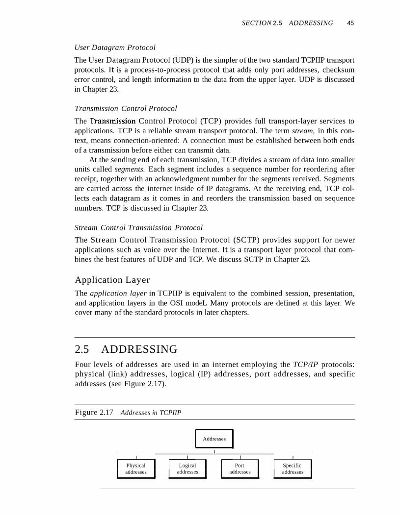
2.5 ADDRESSINGFour levels of addresses are used in an internet employing the TCP/IP protocols:physical (link) addresses, logical (IP) addresses, port addresses, and specificaddresses (see Figure 2.17).
Figure 2.17 Addresses in TCPIIP
Addresses
II I I I
Physical Logical Port Specificaddresses addresses addresses addresses
46 CHAPTER 2 NETWORK MODELS
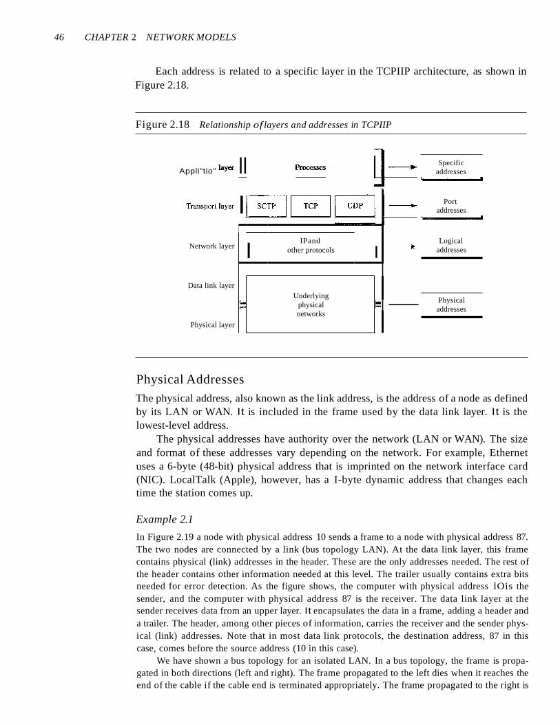
Each address is related to a specific layer in the TCPIIP architecture, as shown inFigure 2.18.
Figure 2.18 Relationship of layers and addresses in TCPIIP
Physicaladdresses
• Specificaddresses
• Portaddresses
.. LogicaladdressesII
IPandother protocols
Underlying
~ physical ~networks
Physical layer
Appli"tio" I,,", II p=,= 11-----.- '---..I
T""port I,,", IEJG [j~ 1-----.- '---..I
Network layer
Data link layer
Physical Addresses
The physical address, also known as the link address, is the address of a node as definedby its LAN or WAN. It is included in the frame used by the data link layer. It is thelowest-level address.
The physical addresses have authority over the network (LAN or WAN). The sizeand format of these addresses vary depending on the network. For example, Ethernetuses a 6-byte (48-bit) physical address that is imprinted on the network interface card(NIC). LocalTalk (Apple), however, has a I-byte dynamic address that changes eachtime the station comes up.
Example 2.1
In Figure 2.19 a node with physical address 10 sends a frame to a node with physical address 87.The two nodes are connected by a link (bus topology LAN). At the data link layer, this framecontains physical (link) addresses in the header. These are the only addresses needed. The rest ofthe header contains other information needed at this level. The trailer usually contains extra bitsneeded for error detection. As the figure shows, the computer with physical address lOis thesender, and the computer with physical address 87 is the receiver. The data link layer at thesender receives data from an upper layer. It encapsulates the data in a frame, adding a header anda trailer. The header, among other pieces of information, carries the receiver and the sender physical (link) addresses. Note that in most data link protocols, the destination address, 87 in thiscase, comes before the source address (10 in this case).
We have shown a bus topology for an isolated LAN. In a bus topology, the frame is propagated in both directions (left and right). The frame propagated to the left dies when it reaches theend of the cable if the cable end is terminated appropriately. The frame propagated to the right is

SECTION 2.5 ADDRESSING 47
Figure 2.19 Physical addresses
53 __
Sender
__ 28
Destination address doesnot match; the packet is
dropped
•••LAN
"Receiver
sent to every station on the network. Each station with a physical addresses other than 87 dropsthe frame because the destination address in the frame does not match its own physical address.The intended destination computer, however, finds a match between the destination address in theframe and its own physical address. The frame is checked, the header and trailer are dropped, andthe data part is decapsulated and delivered to the upper layer.
Example 2.2
As we will see in Chapter 13, most local-area networks use a 48-bit (6-byte) physical addresswritten as 12 hexadecimal digits; every byte (2 hexadecimal digits) is separated by a colon, asshown below:
07:01:02:01 :2C:4BA 6-byte (12 hexadecimal digits) physical address
Logical Addresses
Logical addresses are necessary for universal communications that are independent ofunderlying physical networks. Physical addresses are not adequate in an internetworkenvironment where different networks can have different address formats. A universaladdressing system is needed in which each host can be identified uniquely, regardlessof the underlying physical network.
The logical addresses are designed for this purpose. A logical address in the Internetis currently a 32-bit address that can uniquely define a host connected to the Internet. Notwo publicly addressed and visible hosts on the Internet can have the same IP address.
Example 2.3
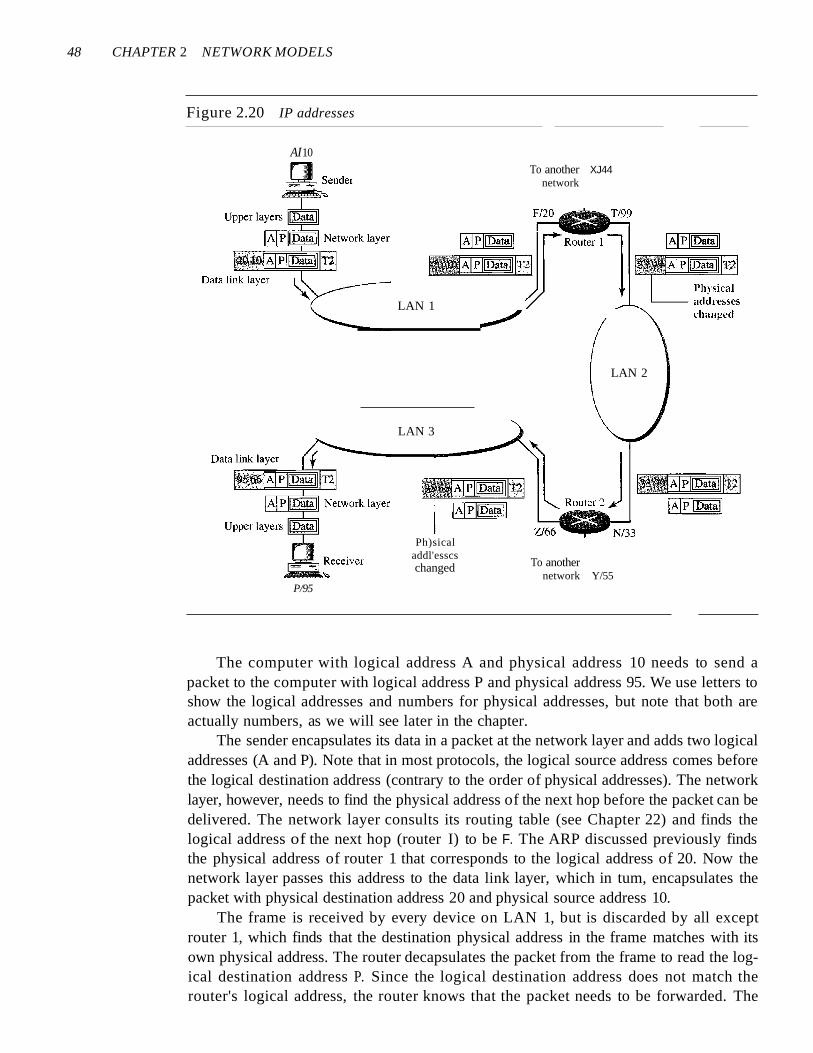
Figure 2.20 shows a part of an internet with two routers connecting three LANs. Each device(computer or router) has a pair of addresses (logical and physical) for each connection. In thiscase, each computer is connected to only one link and therefore has only one pair of addresses.Each router, however, is connected to three networks (only two are shown in the figure). So eachrouter has three pairs of addresses, one for each connection. Although it may obvious that eachrouter must have a separate physical address for each connection, it may not be obvious why itneeds a logical address for each connection. We discuss these issues in Chapter 22 when we discuss routing.
48 CHAPTER 2 NETWORK MODELS
Figure 2.20 IP addresses
AI10
LAN 2
To anothernetwork Y/55
To another XJ44network
Ph)sicaladdl'esscschanged
LAN 3
-~~_~I~I JRouterll
~tE]
LAN 1
P/95
The computer with logical address A and physical address 10 needs to send apacket to the computer with logical address P and physical address 95. We use letters toshow the logical addresses and numbers for physical addresses, but note that both areactually numbers, as we will see later in the chapter.
The sender encapsulates its data in a packet at the network layer and adds two logicaladdresses (A and P). Note that in most protocols, the logical source address comes beforethe logical destination address (contrary to the order of physical addresses). The networklayer, however, needs to find the physical address of the next hop before the packet can bedelivered. The network layer consults its routing table (see Chapter 22) and finds thelogical address of the next hop (router I) to be F. The ARP discussed previously findsthe physical address of router 1 that corresponds to the logical address of 20. Now thenetwork layer passes this address to the data link layer, which in tum, encapsulates thepacket with physical destination address 20 and physical source address 10.
The frame is received by every device on LAN 1, but is discarded by all exceptrouter 1, which finds that the destination physical address in the frame matches with itsown physical address. The router decapsulates the packet from the frame to read the logical destination address P. Since the logical destination address does not match therouter's logical address, the router knows that the packet needs to be forwarded. The
SECTION 2.5 ADDRESSING 49
router consults its routing table and ARP to find the physical destination address of thenext hop (router 2), creates a new frame, encapsulates the packet, and sends it to router 2.
Note the physical addresses in the frame. The source physical address changesfrom 10 to 99. The destination physical address changes from 20 (router 1 physicaladdress) to 33 (router 2 physical address). The logical source and destination addressesmust remain the same; otherwise the packet will be lost.
At router 2 we have a similar scenario. The physical addresses are changed, and anew frame is sent to the destination computer. When the frame reaches the destination,the packet is decapsulated. The destination logical address P matches the logical addressof the computer. The data are decapsulated from the packet and delivered to the upperlayer. Note that although physical addresses will change from hop to hop, logicaladdresses remain the same from the source to destination. There are some exceptions tothis rule that we discover later in the book.
The physical addresses will change from hop to hop,but the logical addresses usually remain the same.
Port Addresses
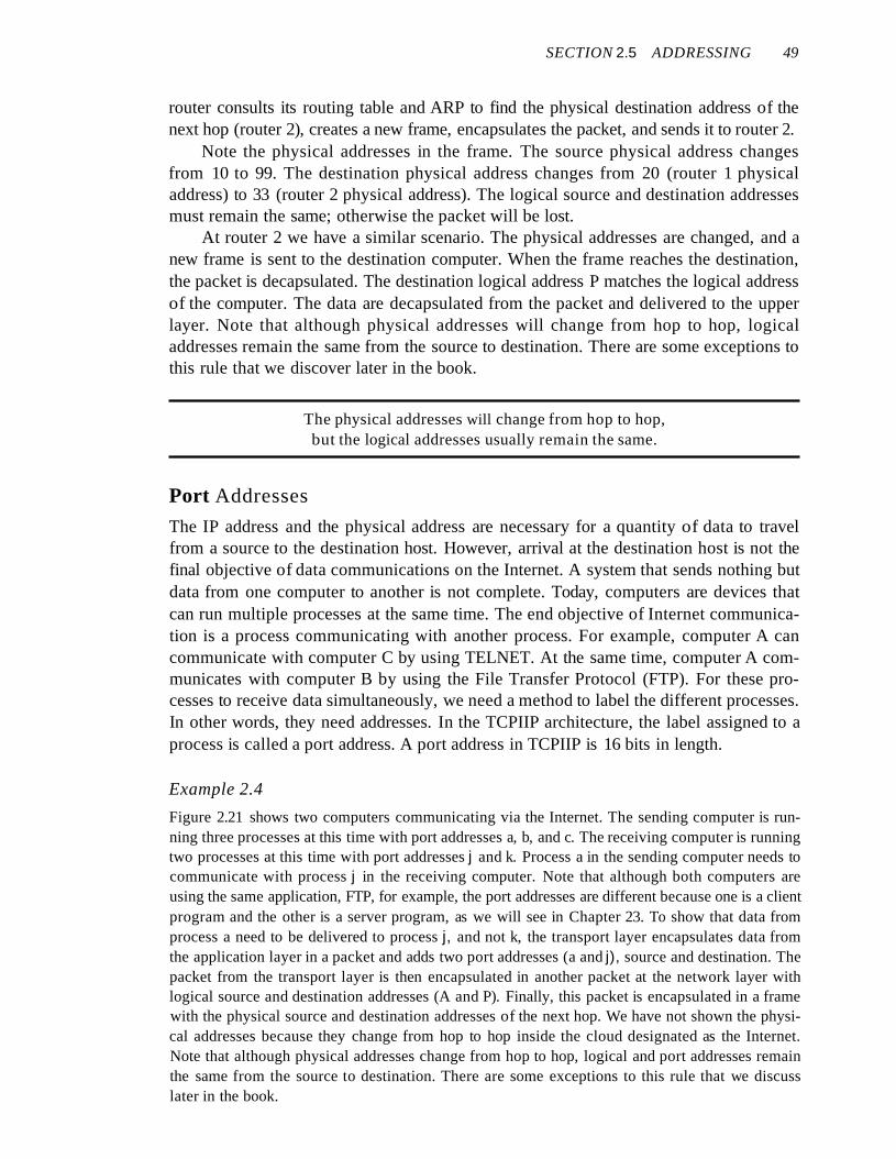
The IP address and the physical address are necessary for a quantity of data to travelfrom a source to the destination host. However, arrival at the destination host is not thefinal objective of data communications on the Internet. A system that sends nothing butdata from one computer to another is not complete. Today, computers are devices thatcan run multiple processes at the same time. The end objective of Internet communication is a process communicating with another process. For example, computer A cancommunicate with computer C by using TELNET. At the same time, computer A communicates with computer B by using the File Transfer Protocol (FTP). For these processes to receive data simultaneously, we need a method to label the different processes.In other words, they need addresses. In the TCPIIP architecture, the label assigned to aprocess is called a port address. A port address in TCPIIP is 16 bits in length.
Example 2.4
Figure 2.21 shows two computers communicating via the Internet. The sending computer is running three processes at this time with port addresses a, b, and c. The receiving computer is runningtwo processes at this time with port addresses j and k. Process a in the sending computer needs tocommunicate with process j in the receiving computer. Note that although both computers areusing the same application, FTP, for example, the port addresses are different because one is a clientprogram and the other is a server program, as we will see in Chapter 23. To show that data fromprocess a need to be delivered to process j, and not k, the transport layer encapsulates data fromthe application layer in a packet and adds two port addresses (a and j), source and destination. Thepacket from the transport layer is then encapsulated in another packet at the network layer withlogical source and destination addresses (A and P). Finally, this packet is encapsulated in a framewith the physical source and destination addresses of the next hop. We have not shown the physical addresses because they change from hop to hop inside the cloud designated as the Internet.Note that although physical addresses change from hop to hop, logical and port addresses remainthe same from the source to destination. There are some exceptions to this rule that we discusslater in the book.

50 CHAPTER 2 NETWORK MODELS
Figure 2.21 Port addresses
abc
DD
- - - - Data link layer - - --
Internet
j k
DD
The physical addresses change from hop to hop,but the logical and port addresses usually remain the same.
Example 2.5
As we will see in Chapter 23, a port address is a 16-bit address represented by one decimal numher as shown.
753A 16-bit port address represented as one single number
Specific Addresses
Some applications have user-friendly addresses that are designed for that specific address.Examples include the e-mail address (for example, [email protected]) and the UniversalResource Locator (URL) (for example, www.mhhe.com). The first defines the recipient ofan e-mail (see Chapter 26); the second is used to find a document on the World Wide Web(see Chapter 27). These addresses, however, get changed to the corresponding port andlogical addresses by the sending computer, as we will see in Chapter 25.
2.6 RECOMMENDED READINGFor more details about subjects discussed in this chapter, we recommend the followingbooks and sites. The items enclosed in brackets, [...] refer to the reference list at theend of the text.
SECTION 2. 7 KEY TERMS 51
Books
Network models are discussed in Section 1.3 of [Tan03], Chapter 2 of [For06], Chapter 2of [Sta04], Sections 2.2 and 2.3 of [GW04], Section 1.3 of [PD03], and Section 1.7 of[KR05]. A good discussion about addresses can be found in Section 1.7 of [Ste94].
Sites
The following site is related to topics discussed in this chapter.
o www.osi.org! Information about OS1.
RFCs
The following site lists all RFCs, including those related to IP and port addresses.
o www.ietLorg/rfc.html
2.7 KEY TERMSaccess control
Address Resolution Protocol (ARP)
application layer
best-effort delivery
bits
connection control
data link layer
encoding
error
error control
flow control
frame
header
hop-to-hop delivery
host-to-host protocol
interface
Internet Control Message Protocol(ICMP)
Internet Group Message Protocol (IGMP)
logical addressing
mail service
network layer
node-to-node delivery
open system
Open Systems Interconnection (OSI)model
peer-to-peer process
physical addressing
physical layer
port address
presentation layer
process-to-process delivery
Reverse Address Resolution Protocol(RARP)
routing
segmentation
session layer
source-to-destination delivery
Stream Control Transmission Protocol(SCTP)
synchronization point
TCPIIP protocol suite
trailer
Transmission Control Protocol (TCP)
transmission rate
transport layer
transport level protocols
User Datagram Protocol (UDP)
52 CHAPTER 2 NETWORK MODELS
2.8 SUMMARYo The International Standards Organization created a model called the Open Systems
Interconnection, which allows diverse systems to communicate.
U The seven-layer OSI model provides guidelines for the development of universallycompatible networking protocols.
o The physical, data link, and network layers are the network support layers.
o The session, presentation, and application layers are the user support layers.
D The transport layer links the network support layers and the user support layers.
o The physical layer coordinates the functions required to transmit a bit stream overa physical medium.
o The data link layer is responsible for delivering data units from one station to thenext without errors.
o The network layer is responsible for the source-to-destination delivery of a packetacross multiple network links.
[J The transport layer is responsible for the process-to-process delivery of the entiremessage.
D The session layer establishes, maintains, and synchronizes the interactions betweencommunicating devices.
U The presentation layer ensures interoperability between communicating devicesthrough transformation of data into a mutually agreed upon format.
o The application layer enables the users to access the network.
o TCP/IP is a five-layer hierarchical protocol suite developed before the OSI model.
U The TCP/IP application layer is equivalent to the combined session, presentation,and application layers of the OSI model.
U Four levels of addresses are used in an internet following the TCP/IP protocols: physical (link) addresses, logical (IP) addresses, port addresses, and specific addresses.
o The physical address, also known as the link address, is the address of a node asdefined by its LAN or WAN.
L,J The IP address uniquely defines a host on the Internet.
U The port address identifies a process on a host.
o A specific address is a user-friendly address.
2.9 PRACTICE SET
Review Questions
I. List the layers of the Internet model.
2. Which layers in the Internet model are the network support layers?
3. Which layer in the Internet model is the user support layer?
4. What is the difference between network layer delivery and transport layer delivery?

SECTION 2.9 PRACTICE SET 53
5. What is a peer-to-peer process?
6. How does information get passed from one layer to the next in the Internetmodel?
7. What are headers and trailers, and how do they get added and removed?
X. What are the concerns of the physical layer in the Internet model?
9. What are the responsibilities of the data link layer in the Internet model?
10. What are the responsibilities of the network layer in the Internet model?
II. What are the responsibilities of the transport layer in the Internet model?
12. What is the difference between a port address, a logical address, and a physicaladdress?
13. Name some services provided by the application layer in the Internet model.
14. How do the layers of the Internet model correlate to the layers of the OSI model?
Exercises
15. How are OSI and ISO related to each other?
16. Match the following to one or more layers of the OSI model:
a. Route determination
b. Flow control
c. Interface to transmission media
d. Provides access for the end user
I 7. Match the following to one or more layers of the OSI model:
a. Reliable process-to-process message delivery
b. Route selection
c. Defines frames
d. Provides user services such as e-mail and file transfer
e. Transmission of bit stream across physical medium
\8. Match the following to one or more layers of the OSl model:
a. Communicates directly with user's application program
b. Error correction and retransmission
c. Mechanical, electrical, and functional interface
d. Responsibility for carrying frames between adjacent nodes
I 9. Match the following to one or more layers of the OSI model:
a. Format and code conversion services
b. Establishes, manages, and terminates sessions
c. Ensures reliable transmission of data
d. Log-in and log-out procedures
e. Provides independence from differences in data representation
20. In Figure 2.22, computer A sends a message to computer D via LANl, router Rl,and LAN2. Show the contents of the packets and frames at the network and datalink layer for each hop interface.

54 CHAPTER 2 NETWORK MODELS
Figure 2.22 Exercise 20
Sender 8/42
LAN 1
Rl
LAN 2 Sender
21. In Figure 2.22, assume that the communication is between a process running atcomputer A with port address i and a process running at computer D with portaddress j. Show the contents of packets and frames at the network, data link, andtransport layer for each hop.
22. Suppose a computer sends a frame to another computer on a bus topology LAN.The physical destination address of the frame is corrupted during the transmission.What happens to the frame? How can the sender be informed about the situation?
23. Suppose a computer sends a packet at the network layer to another computersomewhere in the Internet. The logical destination address of the packet is corrupted. What happens to the packet? How can the source computer be informed ofthe situation?
24. Suppose a computer sends a packet at the transport layer to another computersomewhere in the Internet. There is no process with the destination port addressrunning at the destination computer. What will happen?
25. If the data link layer can detect errors between hops, why do you think we needanother checking mechanism at the transport layer?
Research Activities
26. Give some advantages and disadvantages of combining the session, presentation,and application layer in the OSI model into one single application layer in theInternet model.
27. Dialog control and synchronization are two responsibilities of the session layer inthe OSI model. Which layer do you think is responsible for these duties in theInternet model? Explain your answer.
28. Translation, encryption, and compression are some of the duties of the presentationlayer in the OSI model. Which layer do you think is responsible for these duties inthe Internet model? Explain your answer.
29. There are several transport layer models proposed in the OSI model. Find all ofthem. Explain the differences between them.
30. There are several network layer models proposed in the OSI model. Find all ofthem. Explain the differences between them.

Physical Layerand Media
Objectives
We start the discussion of the Internet model with the bottom-most layer, the physicallayer. It is the layer that actually interacts with the transmission media, the physical partof the network that connects network components together. This layer is involved inphysically carrying information from one node in the network to the next.
The physical layer has complex tasks to perform. One major task is to provideservices for the data link layer. The data in the data link layer consists of Os and Is organized into frames that are ready to be sent across the transmission medium. This streamof Os and Is must first be converted into another entity: signals. One of the services provided by the physical layer is to create a signal that represents this stream of bits.
The physical layer must also take care of the physical network, the transmissionmedium. The transmission medium is a passive entity; it has no internal program orlogic for control like other layers. The transmission medium must be controlled by thephysical layer. The physical layer decides on the directions of data flow. The physicallayer decides on the number of logical channels for transporting data coming fromdifferent sources.
In Part 2 of the book, we discuss issues related to the physical layer and the transmission medium that is controlled by the physical layer. In the last chapter of Part 2, wediscuss the structure and the physical layers of the telephone network and the cablenetwork.
Part 2 of the book is devoted to the physical layerand the transmission media.
Chapters
This part consists of seven chapters: Chapters 3 to 9.
Chapter 3
Chapter 3 discusses the relationship between data, which are created by a device, andelectromagnetic signals, which are transmitted over a medium.
Chapter 4
Chapter 4 deals with digital transmission. We discuss how we can covert digital oranalog data to digital signals.
Chapter 5
Chapter 5 deals with analog transmission. We discuss how we can covert digital oranalog data to analog signals.
Chapter 6
Chapter 6 shows how we can use the available bandwidth efficiently. We discuss twoseparate, but related topics, multiplexing and spreading.
Chapter 7
After explaining some ideas about data and signals and how we can use them efficiently, we discuss the characteristics of transmission media, both guided andunguided, in this chapter. Although transmission media operates under the physicallayer, they are controlled by the physical layer.
Chapter 8
Although the previous chapters in this part are issues related to the physical layer ortransmission media, Chapter 8 discusses switching, a topic that can be related to severallayers. We have included this topic in this part of the book to avoid repeating the discussion for each layer.
Chapter 9
Chapter 9 shows how the issues discussed in the previous chapters can be used in actualnetworks. In this chapter, we first discuss the telephone network as designed to carryvoice. We then show how it can be used to carry data. Second, we discuss the cable network as a television network. We then show how it can also be used to carry data.