networked cascade control system design for...
TRANSCRIPT
Research Article119867infin Networked Cascade Control System Design for TurboshaftEngines with Random Packet Dropouts
Xiaofeng Liu and Xu Sun
School of Transportation Science and Engineering Beijing University of Aeronautics and Astronautics Beijing China
Correspondence should be addressed to Xiaofeng Liu liuxfbuaaeducn
Received 1 December 2016 Accepted 29 January 2017 Published 16 February 2017
Academic Editor Wen Bao
Copyright copy 2017 Xiaofeng Liu and Xu Sun This is an open access article distributed under the Creative Commons AttributionLicense which permits unrestricted use distribution and reproduction in any medium provided the original work is properlycited
The distributed control architecture becomes more and more important in future gas turbine engine control systems in which thesensors and actuators will be connected to the controllers via a network Therefore the control problem of network-enabled high-performance distributed engine control (DEC) has come to play an important role in modern gas turbine control systems whiledue to the properties of the network the packet dropouts must be considered This study introduces a distributed control systemarchitecture based on a networked cascade control system (NCCS) Typical turboshaft engine distributed controllers are designedbased on the NCCS framework with 119867infin state feedback under random packet dropouts The sufficient robust stable conditionsare derived via the Lyapunov stability theory and linear matrix inequality approach Simulations illustrate the effectiveness of thepresented method
1 Introduction
The distributed control system (DCS) is a control systemwherein control elements are distributed throughout thesystem This is in contrast to the centralized ones which usea single controller at a central location In a DCS a hierarchyof controllers is connected by communication networks forinformationdata transmission The advantages of the DCSarchitecture such as reduction of system weight higherreliability modularity and less low life cost merit increasingattention from industrial companies and engineers
Conventional gas turbine engine control systems aredesigned as a centralized architecture (which called as FullAuthority Digital Engine Control FADEC) to protect thecontrol elements from the extreme environment [1] Whilewith the increasingly development of sophisticated electron-ics with higher reliability in high temperature environmentthe requirements of increased performance more convenientoperation reduction of design and maintenance cost makethe control system to use a more effective architecture Thusthe distributed engine control (DEC) architecture came intobeing [2 3]
Due to the distributed architecture the sensors andcontrollers are connected by the communication networks aswell as between the controllers and the actuators DEC seeksto advance the state of the art in gas turbine engine controlsystems by using a digital communication network with amore robust network This will lead to the development ofgas turbine engine control systems with greater extensibilityand higher capacity for upgrades DEC is extensively studiedin [2 4ndash7] and the references therein
The DEC architecture can be viewed as an NCCS Forexample the GE T700 turboshaft engine is a two-spool gasturbine engine consisting of a gas generator and a free powerturbine [8 9] and the power turbine is connected to the rotorsystem by a shaft and a gear box Conventionally the powerturbine can be considered as a part of the rotor system [10]The input of the rotor system is the gas generatorrsquos output andshaft torque therefore the whole turboshaft engine systemcombined with control systems can be reviewed as a cascadecontrol system (CCS) [11]
As for the DEC using the communication networks toclose the control loop there are fundamental factors to affectthe DEC system They include network-induced time delay
HindawiInternational Journal of Aerospace EngineeringVolume 2017 Article ID 5435090 12 pageshttpsdoiorg10115520175435090
2 International Journal of Aerospace Engineering
packet dropouts and bandwidth constraints [12 13] There-fore to guarantee the desired performance and to ensurestability the control system should be robust to these factorsThe network-induced time delay in NCCSs occurs when thesensors controllers and actuators transfer informationdatathrough the networks and it can degrade the performanceof the control systems and even can destabilize the system[14] Since the network-induced time delay is unavoidable inthe NCCSs the existing literature such as [15ndash18] and thereferences therein has discussed the time delay and manyuseful approaches have been proposed and even appliedto the industrial systems see [19ndash21] and the referencestherein
However few papers have discussed the DEC robustcontrol in gas turbine engine control systems For exampleBelapurkar et al [22] analyzed the stability of set-pointcontroller for partiallyDEC systemswith time delays by usingLQR method Yedavalli et al [13] discussed the stability ofDEC systems under communication packet dropoutsMerrillet al [2] provided a DEC design approach based on quadraticinvariance optimal control theory to the control performanceof various types of decentralized network configurations
This paper is concerned with the problem of 119867infin con-troller design for gas turbine engine distributed control byusing state feedback control in the formofNCCSswith packetdropoutsThe rest of the paper is organized as follows In Sec-tion 2 the architecture of distributed engine control system isthoroughly described and the state feedback control problemis formed 119867infin state feedback controllers are designed basedon Lyapunov stability theory and LMI approach in Section 3A numerical simulation example is presented in Section 4 toillustrate the effectiveness of the approach Conclusionwill befound in Section 5
Notation Throughout the paper the superscripts ldquo119879rdquo andldquo(minus1)rdquo represent matrix transposition and matrix inverserespectively sdot refers to the Euclidean vector norm and119864[sdot] stands for the mathematical expectation operator withrespect to the given probability measure P In symmetricblock matrices or long matrix expressions an asterisk (lowast)represented a term that is induced by symmetry diagsdotstands for a block-diagonal matrix
2 Problem Formulation
21 DEC System Architecture Description This study utilizeda GE T700 turboshaft engine Figure 1 shows the simplifieddiagram The inputs to the gas generator were the powerturbine speed set value 119873119875 and the fuel flow rate 119882119865 Theoutputs were the gas generator speed 119873119866 engine torquetransmitted by the power turbine shaft119876119878 compressor staticdischarge pressure 1198751198783 and power turbine inlet temperature11987945 The controller design process begins with a linearizedstate-spacemodel of the system Figure 2 shows the simplifiedmodel in this case
Control laws essentially work to maintain 119873119875 con-stant at the set point by modulating 119882119865 The controlaccomplishes this by scheduling a nominal 119873119866 speed asa function of XCPC 1198791 and 1198751 The control trims this
Gearbox
Rotor system
Gasgenerator
Blade dynamics
+
Wind gusts andother disturbances
XCPC
WF
NMRNP
NG
T45PS3
QS
QR
minus
Figure 1 Block diagram of the open-loop gas generatorrotor sys-tem
119873119866 demand to isochronously adjust 119873119875 to 119873119875 set inputPLA position limits the maximum permissible 119873119866 whilethe control further limits the maximum 11987945 The controllimits the 119873119866 accelerationdeceleration rate as a functionof 119873119866 scheduled 1198821198651198751198783 limit The DEC discussed hereinhas one network which is inserted in the gas generatorcontroller and the gas generator Figure 3 shows the archi-tecture The abovementioned description illustrates that theGE T700 control structure is a cascade control structurewherein the desired primary process output can only becontrolled by controlling the secondary control processoutput
Primary Plant The state-space representation of the rotorsystem is provided by the following equation [9 23]
[[[[
119875MR
MR
]]]]⏟⏟⏟⏟⏟⏟⏟⏟⏟⏟⏟⏟⏟⏟⏟
1199091(119905)
=[[[[[[[[[[
0 0 minus 11198691198790 minusDAM119869MR
1119869MR
KMR DMR sdot DAM119869MRminus KMR minusDMR119869119879 minus DMR119869MR
]]]]]]]]]]⏟⏟⏟⏟⏟⏟⏟⏟⏟⏟⏟⏟⏟⏟⏟⏟⏟⏟⏟⏟⏟⏟⏟⏟⏟⏟⏟⏟⏟⏟⏟⏟⏟⏟⏟⏟⏟⏟⏟⏟⏟⏟⏟⏟⏟⏟⏟⏟⏟⏟⏟⏟⏟⏟⏟⏟⏟⏟⏟⏟⏟⏟⏟⏟⏟⏟⏟⏟⏟⏟⏟⏟⏟⏟⏟⏟⏟⏟⏟⏟⏟⏟⏟⏟⏟⏟⏟⏟⏟⏟⏟⏟⏟⏟⏟⏟⏟
A1
[[[
119873119875119873MR119876MR
]]]⏟⏟⏟⏟⏟⏟⏟⏟⏟⏟⏟⏟⏟⏟⏟
1199091(119905)
+[[[[[[[
21198691198790
2 sdot DMR119869119879
]]]]]]]⏟⏟⏟⏟⏟⏟⏟⏟⏟⏟⏟⏟⏟⏟⏟⏟⏟⏟⏟⏟⏟⏟⏟
B1
119876119878⏟⏟⏟⏟⏟⏟⏟1199102(119905)
119873119875⏟⏟⏟⏟⏟⏟⏟1199101(119905)
= [1 0 0]⏟⏟⏟⏟⏟⏟⏟⏟⏟⏟⏟⏟⏟⏟⏟1198621
[[[
119873119875119873MR119876MR
]]]
(1)
International Journal of Aerospace Engineering 3
Secondary PlantThe continuous-time linearmodel of the gasgenerator is shown as follows
[[[[[[[[[[[[
119866119878451198783119875
]]]]]]]]]]]]⏟⏟⏟⏟⏟⏟⏟⏟⏟⏟⏟1199092(119905)
=
[[[[[[[[[[[[[[[[[[[[[
1119869119866 sdot120575119876119866120575119873119866 0 0 0 0
2 sdot DMR119869119879 sdot 120575119876119875120575119873119866 0 0 0 2 sdot DMR119869119879 sdot 12057511987611987512057511987311987512057511987945120575119873119866 0 0 0 01205751198751198783120575119873119866 0 0 0 0
2119869119879 sdot120575119876119875120575119873119866 minus 1119869119879 0 0 2119869119879 sdot
120575119876119875120575119873119875
]]]]]]]]]]]]]]]]]]]]]⏟⏟⏟⏟⏟⏟⏟⏟⏟⏟⏟⏟⏟⏟⏟⏟⏟⏟⏟⏟⏟⏟⏟⏟⏟⏟⏟⏟⏟⏟⏟⏟⏟⏟⏟⏟⏟⏟⏟⏟⏟⏟⏟⏟⏟⏟⏟⏟⏟⏟⏟⏟⏟⏟⏟⏟⏟⏟⏟⏟⏟⏟⏟⏟⏟⏟⏟⏟⏟⏟⏟⏟⏟⏟⏟⏟⏟⏟⏟⏟⏟⏟⏟⏟⏟⏟⏟⏟⏟⏟⏟
A2
[[[[[[[[[
119873119866119876119878119879451198751198783119873119875
]]]]]]]]]⏟⏟⏟⏟⏟⏟⏟⏟⏟⏟⏟
1199092(119905)
+
[[[[[[[[[[[[[[[[[[[
1119869119866 sdot1205751198761198661205751198821198652 sdot DMR119869119879 sdot 1205751198761198751205751198821198651205751198794512057511988211986512057511987511987831205751198821198652119869119879 sdot120575119876119875120575119882119865
]]]]]]]]]]]]]]]]]]]⏟⏟⏟⏟⏟⏟⏟⏟⏟⏟⏟⏟⏟⏟⏟⏟⏟⏟⏟⏟⏟⏟⏟⏟⏟⏟⏟⏟⏟⏟⏟⏟⏟⏟⏟⏟⏟
B2
119882119865⏟⏟⏟⏟⏟⏟⏟119906(119905)
+B3119908 (119905)
119876119878⏟⏟⏟⏟⏟⏟⏟1199102(119905)
= [0 1 0 0 0]⏟⏟⏟⏟⏟⏟⏟⏟⏟⏟⏟⏟⏟⏟⏟⏟⏟⏟⏟⏟⏟⏟⏟⏟⏟1198622
[[[[[[[[[
119873119866119876119878119879451198751198783119873119875
]]]]]]]]]
(2)
where119908(119905) is exogenous process white noise signal belongingto 1198972[0infin) and the noise parameters matrix B3 shouldbe used as design parameters to achieve desirable systemfrequency response characteristics [9]
The following assumptions are partially taken from [2425]
(a) The controllers are event-driven The primary con-troller computes the values and sends them to the sec-ondary controller after obtaining the latest samples ofthe primary plant outputs The secondary controllerthen computes the control command and sends it tothe actuator as soon as it receives the latest samples
of the secondary plant and the control output of theprimary plant controller through a common network
(b) The actuator is time-driven In other words the actu-ator actuates the plants once it receives the controlcommand The actuator will then use the previousvalue by zero-order-hold to precede the secondaryprocess in case of packet loss
(c) The sensors are time-driven that is they periodicallysample the outputs and send them to the correspond-ing controllers
(d) The data packet transmitted from the controller to theplant may be delayed The delay is assumed to be afixed one and less than a sampling period ℎ (ie 120591119896 isin[0 ℎ])
(e) The data packet is assumed to be transmitted betweenthe primary and secondary controllers in a singlepacket without any loss However the data packettransmitted between the secondary controller and theactuatormay be delayed ormaymeet a possible failurein a random manner
22 State Feedback Control of DEC System By consideringthe network-induced delay 120591119896 the controllers are event-driven the actuator is time-driven and the engine receivesthe piece-wised control input is given by
119906 (119905) = 2 (119896 minus 1) 119896ℎ le 119905 lt 119896ℎ + 1205911198962 (119896) 119896ℎ + 120591119896 le 119905 lt (119896 + 1) ℎ (3)
2 (119896)=
2 (119896 minus 1) if 1199062 (119896) lost during transmission
1199062 (119896) if 1199062 (119896) transmitted successfully
(4)
that is the actuator receives the signal 1199062(119896) if the data istransmitted successfully otherwise the previous value willbe used in the actuator by zero-order-hold where 1199062(119896) is thecontrol output of the secondary controller
Since the actuator is time-driven the packet loss mayhappen in a random manner Then 2(119896) can be rewrittenby [25 26]
2 (119896) = 120582 (119896) 1199062 (119896) + (1 minus 120582 (119896)) 2 (119896 minus 1) (5)
where 120582(119896) is a Bernoulli distributed stochastic variabletaking the value 0 or 1 120582(119896) = 1 represents the successful statetransmission of the delayed packet and 120582(119896) = 0 describesthe complete packet loss It assumed that 120582(119896) satisfies theBernoulli distribution [27]
Prob 120582 (119896) = 1 = 120572Prob 120582 (119896) = 0 = 1 minus 120572 (6)
where 120572 is a positive scalar 119864[120582(119896) minus 120572] = 0 and 119864[(120582(119896) minus120572)2] = 120572(1 minus 120572)
4 International Journal of Aerospace Engineering
1s
DMR
KMR 1s
2
1s
1s
DAM
+ +
++
++
+
+
+
+
120575WF
120575T45120575WF
120575PS3120575WF
120575QG120575WF
120575QP120575WF
120575T45120575NG
120575PS3120575NG
120575QG120575NG
120575QP120575NG
120575QP120575NP
1JG
1JT120575QS
120575QMR
120575T45
120575PS3
120575NG
120575NP
1JMR
minus
minus
minus
120575NMR
++
++
Figure 2 Block diagram of the simplified linearized gas generator and rotor system
Gas generator Rotor system+r + NetworkK1
x1x2
y1y2u2(k)u1(k)K2
S1
S2
minus minus
u
Figure 3 Block diagram of the NCCS model
Considering the system reference input119873Pr = 0 the staticstate feedback controller is utilized by a discrete-time form
1199062 (119896) = 1199061 (119896) + 1198702 (120572) 1199092 (119896) (7)
where 1198702(120572) is the probability-dependent (packet dropoutsprobability) state feedback gain matrix given by 1198702(120572) =11987021 + 12057211987022 and1198701 is
1199061 (119896) = 11987011199091 (119896) (8)
where 1199091(119896) is the state vector of rotor system in discrete-timeform and1198701 is the state feedback gain
By using (3) the rotor system and engine with samplingperiod [119896ℎ (119896 + 1)ℎ] are discretized to
1199091 (119896 + 1) = 11986011199091 (119896) + 11986111199102 (119896) 1199101 (119896) = 11986211199091 (119896) (9)
where 1198601 = 119890A1ℎ 1198611 = intℎ0119890A1119904119889119904B1 and
1199092 (119896 + 1) = 11986021199092 (119896) + 119861212 (119896 minus 1) + 119861222 (119896)+ 1198613119908 (119896)
1199102 (119896) = 11986221199092 (119896) (10)
International Journal of Aerospace Engineering 5
where 1198602 = 119890A2ℎ 11986121 = intℎℎminus120591119896
119890A2119904119889119904B2 11986122 = intℎminus1205911198960
119890A2119904119889119904B2 and 1198613 = intℎ
0119890A2119904119889119904B3 Then considering the random
packet loss combined (5) and (7) with (10) (10) becomes
1199092 (119896 + 1) = 11986021199092 (119896)+ (11986121 minus (1 minus 120582 (119896)) 11986122) 2 (119896 minus 1)+ 120582 (119896) 11986122 (11987011199091 (119896) + 1198702 (120572) 1199092 (119896))+ 1198613119908 (119896)
1199102 (119896) = 1198622 (119896) 1199092 (119896)
(11)
Thus the discretized system can be further expanded as
1199092 (119896 + 1)= (1198602 + 120572119861221198702 (120572)) 1199092 (119896)
+ (120582 (119896) minus 120572) 11986122 (11987011199091 (119896) + 1198702 (120572) 1199092 (119896))+ 1205721198612211987011199091 (119896) + (11986121 + (1 minus 12057211986122)) 2 (119896 minus 1)+ (120572 minus 120582 (119896)) 119861222 (119896 minus 1) + 1198613119908 (119896)
1199102 (119896) = 1198622 (119896) 1199092 (119896)
(12)
Since the goal of this paper is to design the state con-trollers to regulate the power turbine speed in presence ofdisturbances the output of the closed-loop is determinedby 1199101(119896) and the input is exogenous disturbance 119908(119896)Observing (9) and (12) 1199091(119896) 1199092(119896) and 2(119896minus1) are chosenas the closed-loop state vectors Therefore the closed-loopstate-space form is given by
119909 (119896 + 1) = (119860 (120572) + (120582 (119896) minus 120572) 119861 (120572)) 119909 (119896)+ 119863119908 (119896)
119910 (119896) = 119862119909 (119896) (13)
where 119860(120572) 119861(120572) 119862 and119863 can be seen in
119860 (120572)
= [[[
1198601 11986111198622 0120572119861221198701 1198602 + 120572119861221198702 (120572) 11986121 + (1 minus 120572) 119861221205721198701 1205721198702 (120572) (1 minus 120572) 119868
]]]
119861 (120572) = [[[
0 0 0119861221198701 119861221198702 (120572) minus119861221198701 1198702 (120572) minus119868
]]]
119862 = [[[[
119862119879100]]]]
119879
119863 = [[[011986130
]]]
(14)
3 Main Results
31 System Performance Requirement In this paper the goalis to design controllers (7) and (8) for the turboshaft engineNCCS such that in the presence of randompacket losses theclosed-loop system (13) is stable and the 119867infin performanceconstraint is satisfied [28]
infinsum119896=0
119864 [1003817100381710038171003817119910 (119896)10038171003817100381710038172] lt 1205742 infinsum119896=0
119864 [119908 (119896)2] (15)
for all nonzero 119908(119896) where 120574 gt 0 is a prescribed scalar
32 Controller Design
Lemma 1 (Schur complement) Given constant matrices Ω1Ω2 and Ω3 where Ω1 = Ω1198791 and Ω2 = Ω1198792 gt 0 then Ω1 +Ω1198793Ωminus12 Ω3 lt 0 if and only if
[Ω1 Ω1198793Ω3 minusΩ2] lt 0
119900119903 [minusΩ2 Ω3Ω1198793 Ω1] lt 0
(16)
Theorem 2 Let the positive scalar 120572 be given The closed-loopsystem (13) is stable with an119867infin performance index 120574 if thereexist symmetric positive definite matrices 119875 and matrices 11987711198772 1198773K1K21 andK22 such that the following LMI holds
[[[[[[[[[
1198741 0 1198742 1198743 1198744lowast minus1205742119868 1198745 0 0lowast lowast 1198746 0 0lowast lowast lowast 1198746 0lowast lowast lowast lowast minus119868
]]]]]]]]]
lt 0 (17)
6 International Journal of Aerospace Engineering
where
1198741 = 119875 minus diag 1198771 + 1198771198791 1198772 + 1198771198792 1198773 + 1198771198793 1198742
= [[[[
11987711198601198791 120572K119879111986111987922 120572K1198791119877119879211986211987921198611198791 11987711987921198601198792 + 120572K1198792 (120572) 11986111987922 K1198792 (120572)
0 119877119879311986111987921 + (1 minus 120572) 119877119879311986111987922 (1 minus 120572) 1198771198793]]]]
1198743 = [[[[
0 K119879111986111987922 K1198791
0 K1198792 (120572) 11986111987922 K1198792 (120572)0 minus119877119879311986111987922 minus1198771198793
]]]]
1198744 = [[[[
1198771198791119862119879100
]]]]
1198745 = [[[011986130
]]]
119879
1198746 = minus119875K2 (120572) = K21 + 120572K22
(18)
and the state feedback gain matrices can be gained by
1198701 = K1119877minus11 11987021 = K21119877minus12 11987022 = K22119877minus13
(19)
Proof In order to conclude the controller design conditionsthe following Lyapunov function can be defined
119881 (119896) = 119909119879 (119896) 119875minus1119909 (119896) (20)
Now for any nonzero 119908(119896)
119864 [119881 (119896 + 1)] minus 119864 [119881 (119896)] + 119864 [119910 (119896)119879 119910 (119896)]minus 1205742119864 [119908 (119896)119879119908 (119896)] = 119864 [(119860 (120572)+ (120582 (119896) minus 120572) 119861 (120572) 119909 (119896 + 1) + 119863119908 (119896))119879 119875minus1 (119860 (120572)+ (120582 (119896) minus 120572) 119861 (120572) 119909 (119896 + 1) + 119863119908 (119896)) minus 119909 (119896)119879sdot 119875minus1119909 (119896) + 119910 (119896)119879 119910 (119896) minus 1205742119908 (119896)119879119908 (119896)]le 119864 [(119860 (120572119909 (119896))119879 119875minus1(119860 (120572119909 (119896)) + 120572 (1 minus 120572)sdot 119909119879 (119896) 119861119879 (120572) 119875minus1119861 (120572) 119909 (119896) minus 119909 (119896)119879 119875minus1119909 (119896)+ 119910 (119896)119879 119910 (119896) minus 1205742119908 (119896)119879119908 (119896)]= 119864[[119909 (119896)
119908 (119896)]119879 sdot 119874 (120572) sdot [119909 (119896)
119908 (119896)]]
(21)
where 119874(120572) can be seen in
119874 (120572) = [119860 (120572)119879 119875minus1119860 (120572) + 120572 (1 minus 120572) 119861 (120572)119879 119875minus1119861 (120572) + 119862119879119862 minus 119875minus1 119860 (120572)119879 119875minus1119863119863119879119875minus1119860 (120572) 119863119879119875minus1119863 minus 1205742119868] (22)
and 119874(120572) can be rewritten in
119874 (120572) = ([minus119875minus1 0lowast minus1205742119868] + [119860 (120572)119879
119863119879 ] sdot 119875minus1
sdot [119860 (120572) 119863] + 120572 (1 minus 120572) [119861 (120572)1198790 ] sdot 119875minus1
sdot [119861 (120572) 0] + [1198621198790 ] sdot [119862 0])
(23)
Thus by applying Lemma 1 (24) can be obtained
119874 (120572)
=[[[[[[[[[
minus119875minus1 0 119860 (120572)119879 120572 (1 minus 120572) 119861 (120572)119879 119862119879lowast minus1205742119868 119863119879 0 0lowast lowast minus119875 0 0lowast lowast lowast minus119875 0lowast lowast lowast lowast minus119868
]]]]]]]]] (24)
Now the goal is to prove 119874(120572) lt 0 By means of thepartitionmatrices 119877 = diag1198771 1198772 1198773 119875 the values of119860(120572)
International Journal of Aerospace Engineering 7
119861(120572) 119862119863 andK1K21 andK22 in LMI (17) the followinginequality (25) can be gotten
[[[[[[[[[
119875 minus 119877 + 119877119879 0 119877119879119860 (120572)119879 120572 (1 minus 120572) 119877119879119861 (120572)119879 119877119879119862119879lowast minus1205742119868 119863119879 0 0lowast lowast minus119875 0 0lowast lowast lowast minus119875 0lowast lowast lowast lowast minus119868
]]]]]]]]]
lt 0
(25)
If (25) holds then by using 119875 minus 2119877 ge minus119877119879119875minus1119877 thefollowing inequality (26) can be gained
[[[[[[[[[
minus119877119879119875minus1119877 0 119877119879119860 (120572)119879 120572 (1 minus 120572) 119877119879119861 (120572)119879 119877119879119862119879lowast minus1205742119868 119863119879 0 0lowast lowast minus119875 0 0lowast lowast lowast minus119875 0lowast lowast lowast lowast minus119868
]]]]]]]]]
lt 0
(26)
Equation (17) can then be obtained by pre- and postmul-tiplying (26) by diag(119877minus1 119868 119868 119868 119868) Therefore for zero to infinwith respect to 119896 it yieldsinfinsum119896=0
119864 [1003817100381710038171003817119910 (119896)10038171003817100381710038172] lt 1205742 infinsum119896=0
119864 [119908 (119896)2] + 119864 [119881 (0)]minus 119864 [119881 (infin)]
(27)
Since [ 119909(0)119908(0) ] = [ 00 ] the closed-loop system (13) is stable andit satisfies (15)
Algorithm for the Controllers Design
(a) The continuous closed-loop system parameters arederived based on Figure 2
(b) The continuous system parameters are discretized
(c) The convex optimization problem (17) is solved toobtain the feasible solutions in terms of positive def-inite matrices 119875 nonsingular slack matrices 119877119894 (119894 =1 2 3) and matricesK1K21K22 and 120574
(d) The controller parameters 1198701 11987021 and 11987022 arederived based onTheorem 2
(e) Stop
4 Simulation Examples
This section presents the effectiveness evaluation of the pro-posed method under simulations in the GE T700 turboshaftgas turbine engine DEC control systems The model of theengine is based on partial derivatives calculated from an
accurate nonlinear model [1] The rotor system and the gasgenerator models in continuous time form are provided
[[[[
119875MR
MR
]]]]
= [[[
0 0 minus28571430 minus04533 90662
52650 minus52131 minus425958]]][[[
119873119875119873MR119876MR
]]]
+ [[[5714286
0825714
]]]119876119878
119873119875 = [1 0 0][[[
119873119875119873MR119876MR
]]]
[[[[[[[[[[
119866119878451198783119875
]]]]]]]]]]
=[[[[[[[[[
minus1268 2704 1236 2217 16725467 5721 minus7702 minus7621 5081minus3366 2233 minus1307 minus8332 17211612 2459 minus218 minus6309 17996242 minus7355 minus1042 minus9144 minus1023
]]]]]]]]]
[[[[[[[[[
119873119866119876119878119879451198751198783119873119875
]]]]]]]]]
+[[[[[[[[[
minus1174424535617455935
]]]]]]]]]119882119865 +
[[[[[[[[[
002002002002002
]]]]]]]]]119908
119876119878 = [0 1 0 0 0][[[[[[[[[
119873119866119876119878119879451198751198783119873119875
]]]]]]]]]
(28)
The coefficients after the discretization are provided asfollows
1198601 = [[[09352 00640 minus2267000021 09934 0071800418 minus00413 05952
]]]
8 International Journal of Aerospace Engineering
1198611 = [[[[[
457030036207847
]]]]]
1198621 = [1 0 0] 1198602
=[[[[[[[[[[[[
03927 01572 minus00524 00010 0077206985 10228 minus04391 minus04080 00411minus05933 05866 minus01759 minus08311 0348408005 00546 minus00665 06367 0018701142 minus08350 00242 00769 00953
]]]]]]]]]]]]
11986121 =[[[[[[[[[[[[
minus0015301908035240050201099
]]]]]]]]]]]]
11986122 =[[[[[[[[[
00206009200255300138minus01128
]]]]]]]]]
1198613 =[[[[[[[[[
0121300715minus012140101900328
]]]]]]]]]
1198622 = [0 1 0 0 0] (29)
Simulation 1 Let the packet loss probability value 120572 = 03and given the initial conditions as 1199091(0) = [1 02 02]1198791199092(0) = [09000 04189 07843 06498 10000]119879 the sim-ulation time is 119879 = 20 s sampling time is ℎ = 001 sand assuming that the two network-induced delays are bothequivalent to 120591119896 which is not longer than the sampling period120591119896 = 0005 s The goal of this simulation is to design thecontroller gains such that the closed-loop system is robustlystable with a disturbance attenuation level 120574 gt 0 Theoptimized solution of (17) can be calculated by using the LMItoolbox in MATLAB
119875 = 10minus7 times
[[[[[[[[[[[[[[[[[[[[
minus04640 minus00037 00128 minus00398 00684 00015 minus00110 minus00418 minus00011minus00037 minus05633 minus00005 00001 00003 minus00002 minus00006 minus00005 0000100128 minus00005 minus06465 minus00180 00233 00038 00120 minus00035 minus00015minus00398 00001 minus00180 minus06070 minus00263 00130 00106 minus00424 minus0014200684 00003 00233 minus00263 minus07761 minus00993 00161 01228 minus0032000015 minus00002 00038 00130 minus00993 minus05875 minus00724 00404 minus00347minus00110 minus00006 00120 00106 00161 minus00724 minus05874 00041 00364minus00418 minus00005 minus00035 minus00424 01228 00404 00041 minus05022 minus00119minus00011 00001 minus00015 minus00142 minus00320 minus00347 00364 minus00119 minus05462
]]]]]]]]]]]]]]]]]]]]
1198771 = 10minus5 times [[[
02236 minus00052 00866minus00052 00172 minus0001700866 minus00017 00363
]]]
1198772 = 10minus4 times[[[[[[[[[
00188 00001 00485 minus00217 0000700001 00001 00004 minus00000 0000100485 00004 01304 minus00584 00030minus00217 minus00000 minus00584 00278 0004000007 00001 00030 00040 00237
]]]]]]]]]
International Journal of Aerospace Engineering 9
Table 1 Optimized 120574opt and control parameters for various values of 120572120572 1198701 11987021 amp 11987022 120574opt0 [00009 minus00000 minus00016] [00421 02644 minus00754 minus01307 00297] 02999[0 0 0 0 0]03 [minus00016 minus00001 00035] [minus00380 minus02780 00635 01037 minus00242] 03035[00287 minus00008 00847 minus00323 minus00080]07 [minus00047 minus00003 00102] [minus01013 minus06667 01705 02835 minus00654] 02970[00741 minus00013 02336 minus00698 minus00287]10 [minus00075 minus00004 00162] [minus01611 minus09143 02504 04084 minus00926] 03014[00972 minus00003 03161 minus00869 minus00415]
1198773 = 10minus8 times 687191198701 = [minus00016 minus00001 00035] 11987021 = [minus00380 minus02780 00635 01037 minus00242] 11987022 = [00287 minus00008 00847 minus00323 minus00080] 120574opt = 03035
(30)
Figures 4 and 5 show the responses of the state variablesin the closed-loop system under packet dropouts and thesystem states converge to zeroMeanwhile Figure 6 illustratesthat the gas generator control loop (inner loop) ismuch fasterthan the rotor system control loop (outer loop)Therefore byTheorem 2 the closed-loop system (13) is robust stable with119867infin disturbance-rejection-attenuation level 120574 and it is notedthat the obtained controllers make sure the fast response ofinner loop to eliminate disturbances
Simulation 2 In order to show the effectiveness evaluationof the proposed method under different values of packetloss probability 120572 the obtained state feedback controllerparameters and disturbance attenuation level 120574 are presentedin Table 1 In Table 1 the case 120572 = 0 represents the successfultransmission 120572 = 1 representing the packet dropout and120572 = 1 denotes the complete loss of transmission case
Figures 7 and 8 show that the closed-loop system(13) can be stabilized with or without packet dropoutsFigure 9 illustrates that the dynamical behavior of theclosed-loop system takes longer to converge to zero Fig-ures 10 and 11 show the network-induced packet lossresponses Thus the designed controllers are well suitedfor the considered turboshaft engine model and workwell over the network-induced imperfections and inputdisturbances
5 Conclusions
This study considered the novel robust119867infin distributed enginecontrol problem to guarantee the engine performance withrandom packet dropouts and disturbances A distributedcontrol system architecture of a typical turboshaft enginewas also described accordingly This distributed architec-ture can be transformed into a networked cascade con-trol system The state feedback controllers were designedto robustly stabilize the closed-loop system under packetloss and disturbances The sufficient conditions for sta-bility were derived based on the Lyapunov stability andthe LMI approach The controller design problem underconsideration is solvable if the LMI was feasible Simulationexamples were provided to show the effectiveness of theapproach
Notations
PLA Power lever angle (throttle)119873119866 Gas generator speed119873119875 Power turbine speed119873MR Main rotor blade velocity119876MR Rotor torque state119876119878 Engine shaft torqueXCPC Collective pitch1198751 Inlet pressure
10 International Journal of Aerospace Engineering
0 2 4 6 8 10 12 14 16 18 20Time (s)
minus1
0
1
2
3
4
5
6
7
x1
x11x12x13
Figure 4 Rotor system state response 1199091
0 2 4 6 8 10 12 14 16 18 20
minus05
0
05
1
15
Time (s)
minus1
x2
x21x22x23
x24x25
Figure 5 Gas generator state response 1199092
1198751198783 Static pressure at Station 31198791 Inlet temperature11987945 Interturbine gas temperature119882119865 Fuel flow119869119866 Power turbine inertia119869119879 Lumped power turbinedynamometerinertia119869MR Main rotor blade inertia
KMR Stiffness of the centrifugal restoringsprings
DMR Lag hinge damping
0 2 4 6 8 10 12 14 16 18 20minus02
minus015
minus01
minus005
0
005
u
u1(k)
u2(k)
u2(k)
Number of samples k
Figure 6 Rotor system controller output 119906
0 2 4 6 8 10 12 14 16 18 20minus2
0
2
4
6
8
10
Time (s)
x1
x11 120572 = 00
x12 120572 = 00
x13 120572 = 00
x11 120572 = 03
x12 120572 = 03
x13 120572 = 03
x11 120572 = 07
x12 120572 = 07
x13 120572 = 07
x11 120572 = 10
x12 120572 = 10
x13 120572 = 10
Figure 7 Rotor system state 1199091 under different 120572
DAM Aero damping119903 Reference input119909 Model state vector119910 Model output vector119906 Model input vector120575 Partial derivatives120596 Process white noise
International Journal of Aerospace Engineering 11
15
1
05
0
minus05
minus10 2 4 6 8 10 12 14 16 18 20
Time (s)
x2
x21 120572 = 00
x22 120572 = 00
x23 120572 = 00
x24 120572 = 00
x25 120572 = 00
x21 120572 = 03
x22 120572 = 03
x23 120572 = 03
x24 120572 = 03
x25 120572 = 03
x21 120572 = 07
x22 120572 = 07
x23 120572 = 07
x24 120572 = 07
x25 120572 = 07
x21 120572 = 10
x22 120572 = 10
x23 120572 = 10
x24 120572 = 10
x25 120572 = 10
Figure 8 Gas generator state 1199092 under different 120572
0 2 4 6 8 10 12 14 16 18 20minus002
minus001
0
001
002
003
004
005
006
Time (s)
u1(t)
120572 = 00
120572 = 03
120572 = 07
120572 = 10
Figure 9 Rotor system controller output 1199061 under different 120572
Competing Interests
The authors declare that they have no competing interests
Acknowledgments
The authors would like to thank Professor Ming CaoDr Xiaodong Chen and Dr Qingkai Yang from Uni-versity of Groningen for their thoughtful remarks thatimproved the presentation of this paper This work wassupported by National Natural Science Foundation ofChina (NSFC) [Grant nos 61573035 and 61104146] and theChina Scholarship Council (CSC) [Grant no 201506025-135]
0 2 4 6 8 10 12 14 16 18 20minus06
minus05
minus04
minus03
minus02
minus01
0
01
02
Number of samples k
u2
u2(t) 120572 = 00
u2(k) 120572 = 00
u2(t) 120572 = 03
u2(k) 120572 = 03
u2(t) 120572 = 07
u2(k) 120572 = 07
u2(t) 120572 = 10
u2(k) 120572 = 10
Figure 10 Gas generator controller output 1199062 under different 120572
0 01 02 03 04 05 06 07minus06
minus05
minus04
minus03
minus02
minus01
0
01
u2
120572 = 0
120572 = 03
120572 = 07
120572 = 10
Number of samples k
Figure 11 Gas generator controller output 1199062 under different 120572(partial view)
References
[1] L C Jaw and J D Mattingly Aircraft Engine Controls DesignSystemAnalysis andHealthMonitoring AIAA Reston VaUSA2009
[2] W Merrill J H Kim S Lall S Majerus D Howe and ABehbahani ldquoDistributed engine control design considerationsrdquoin Proceedings of the 46th AIAAASMESAEASEE Joint Propul-sion Conference and Exhibit pp 25ndash28 Nashville Tenn USA2010
[3] D Culley R Thomas and J Saus ldquoConcepts for distributedengine controlrdquo in Proceedings of the 43rd AIAAASMESAEASEE Joint Propulsion Conference amp Exhibit CincinnatiOH USA July 2007
12 International Journal of Aerospace Engineering
[4] P L Shaffer ldquoDistributed control system for turbine enginesrdquoJournal of Engineering for Gas Turbines and Power vol 121 no1 pp 102ndash107 1999
[5] M Watson J Sheldon H Lee C Byington and A BehbahanildquoDistributed integrated PHM and control via smart engineaccessories for future modern aircraftrdquo in Proceedings of the46th AIAAASMESAEASEE Joint Propulsion Conference ampExhibit Nashville Tenn USA 2010
[6] A Behbahani and B Tulpule ldquoPerspective for distributedintelligent engine controls of the futurerdquo in Proceedings of the46th AIAAASMESAEASEE Joint Propulsion Conference andExhibit Nashville Tenn USA July 2010
[7] J A DeCastro C A Palmer and A Behbahani ldquoMeeting therequirements of distributed engine control via decentralizedmodular smart sensingrdquo in Proceedings of the 46thAIAAASMESAEASEE Joint Propulsion Conference andExhibit p 6748 Nashville Tenn USA 2010
[8] M G Ballin ldquoA high fidelity real-time simulation of a smallturboshaft enginerdquo Tech Rep NASA-TM-100991 NASA 1988
[9] W H PfeilMultivariable Control for the GE T700 Engine Usingthe LQGLTR Design Methodology Massachusetts Institute ofTechnology 1984
[10] A Duyar Z Gu and J S Litt ldquoSimplified dynamic model ofthe T700 turboshaft enginerdquo Journal of the American HelicopterSociety vol 40 no 4 pp 62ndash70 1995
[11] R G Franks andCWWorley ldquoQuantitative analysis of cascadecontrolrdquo Industrial amp Engineering Chemistry vol 48 no 6 pp1074ndash1079 1956
[12] D E Culley P J Paluszewski B J Smith and W StoreyldquoThe case for distributed engine control in turbo-shaft enginesystemsrdquo inProceedings of the 65th Annual ForumProceedingsmdashAHS International pp 1732ndash1745 Grapevine Tex USA May2009
[13] R K Yedavalli R K Belapurkar and A Behbahani ldquoDesignof distributed engine control systems for stability under com-munication packet dropoutsrdquo Journal of Guidance Control andDynamics vol 32 no 5 pp 1544ndash1549 2009
[14] W Zhang M S Branicky and S M Phillips ldquoStability ofnetworked control systemsrdquo IEEE Control Systems vol 21 no1 pp 84ndash99 2001
[15] F Yang Z Wang Y S Hung and M Gani ldquoHinfin control fornetworked systems with random communication delaysrdquo IEEETransactions on Automatic Control vol 51 no 3 pp 511ndash5182006
[16] W-A Zhang and L Yu ldquoModelling and control of networkedcontrol systems with both network-induced delay and packet-dropoutrdquo Automatica vol 44 no 12 pp 3206ndash3210 2008
[17] M B Cloosterman N Van de Wouw W P Heemels and HNijmeijer ldquoStability of networked control systems with uncer-tain time-varying delaysrdquo IEEE Transactions on AutomaticControl vol 54 no 7 pp 1575ndash1580 2009
[18] J Wang and H Yang ldquoExponential stability of a class of net-worked control systems with time delays and packet dropoutsrdquoApplied Mathematics and Computation vol 218 no 17 pp8887ndash8894 2012
[19] M EM BenGaid A Cela andYHamam ldquoOptimal integratedcontrol and scheduling of networked control systems withcommunication constraints application to a car suspensionsystemrdquo IEEE Transactions on Control Systems Technology vol14 no 4 pp 776ndash787 2006
[20] A N Venkat I A Hiskens J B Rawlings and S J WrightldquoDistributed MPC strategies with application to power systemautomatic generation controlrdquo IEEE Transactions on ControlSystems Technology vol 16 no 6 pp 1192ndash1206 2008
[21] X Zhu H Zhang D Cao and Z Fang ldquoRobust control of inte-grated motor-transmission powertrain system over controllerarea network for automotive applicationsrdquo Mechanical Systemsand Signal Processing vol 58 pp 15ndash28 2015
[22] R K Belapurkar R K Yedavalli and P J PaluszewskildquoDesign of set-point controller for partially distributed tur-boshaft engine with network faultsrdquo in Proceedings of the47th AIAAASMESAEASEE Joint Propulsion Conference andExhibit San Diego Calif USA August 2011
[23] G Delosreyes and D Gouchoe ldquoThe design of a turboshaftspeed governor using modern control techniquesrdquo NASA-CR-175046 1986
[24] C Huang Y Bai and X Liu ldquoH-infinity state feedback controlfor a class of networked cascade control systems with uncertaindelayrdquo IEEE Transactions on Industrial Informatics vol 6 no 1pp 62ndash72 2010
[25] K Mathiyalagan J H Park and R Sakthivel ldquoNew results onpassivity-based control for networked cascade control systemswith application to power plant boilerturbine systemrdquo Nonlin-ear Analysis Hybrid Systems vol 17 pp 56ndash69 2015
[26] S Hu andW-Y Yan ldquoStability robustness of networked controlsystems with respect to packet lossrdquo Automatica vol 43 no 7pp 1243ndash1248 2007
[27] J V Uspensky Introduction to Mathematical ProbabilityMcGraw-Hill New York NY USA 1937
[28] Z Wang F Yang D W C Ho and X Liu ldquoRobust Hinfincontrol for networked systems with random packet lossesrdquoIEEE Transactions on Systems Man and Cybernetics Part BCybernetics vol 37 no 4 pp 916ndash924 2007
International Journal of
AerospaceEngineeringHindawi Publishing Corporationhttpwwwhindawicom Volume 2014
RoboticsJournal of
Hindawi Publishing Corporationhttpwwwhindawicom Volume 2014
Hindawi Publishing Corporationhttpwwwhindawicom Volume 2014
Active and Passive Electronic Components
Control Scienceand Engineering
Journal of
Hindawi Publishing Corporationhttpwwwhindawicom Volume 2014
International Journal of
RotatingMachinery
Hindawi Publishing Corporationhttpwwwhindawicom Volume 2014
Hindawi Publishing Corporation httpwwwhindawicom
Journal ofEngineeringVolume 2014
Submit your manuscripts athttpswwwhindawicom
VLSI Design
Hindawi Publishing Corporationhttpwwwhindawicom Volume 2014
Hindawi Publishing Corporationhttpwwwhindawicom Volume 2014
Shock and Vibration
Hindawi Publishing Corporationhttpwwwhindawicom Volume 2014
Civil EngineeringAdvances in
Acoustics and VibrationAdvances in
Hindawi Publishing Corporationhttpwwwhindawicom Volume 2014
Hindawi Publishing Corporationhttpwwwhindawicom Volume 2014
Electrical and Computer Engineering
Journal of
Advances inOptoElectronics
Hindawi Publishing Corporation httpwwwhindawicom
Volume 2014
The Scientific World JournalHindawi Publishing Corporation httpwwwhindawicom Volume 2014
SensorsJournal of
Hindawi Publishing Corporationhttpwwwhindawicom Volume 2014
Modelling amp Simulation in EngineeringHindawi Publishing Corporation httpwwwhindawicom Volume 2014
Hindawi Publishing Corporationhttpwwwhindawicom Volume 2014
Chemical EngineeringInternational Journal of Antennas and
Propagation
International Journal of
Hindawi Publishing Corporationhttpwwwhindawicom Volume 2014
Hindawi Publishing Corporationhttpwwwhindawicom Volume 2014
Navigation and Observation
International Journal of
Hindawi Publishing Corporationhttpwwwhindawicom Volume 2014
DistributedSensor Networks
International Journal of
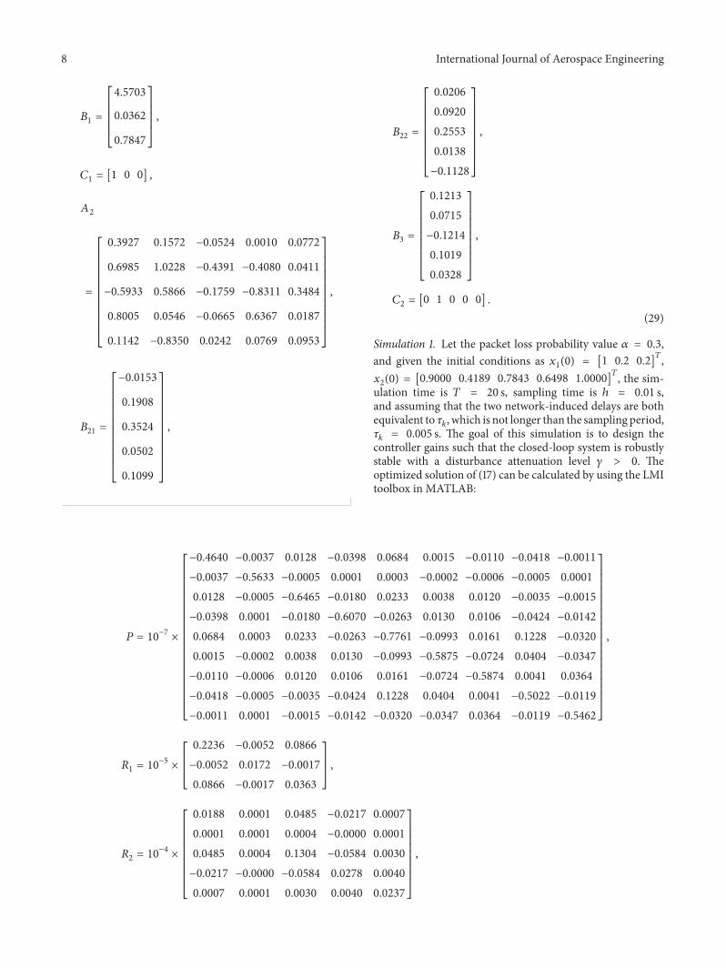

International Journal of
AerospaceEngineeringHindawi Publishing Corporationhttpwwwhindawicom Volume 2014
RoboticsJournal of
Hindawi Publishing Corporationhttpwwwhindawicom Volume 2014
Hindawi Publishing Corporationhttpwwwhindawicom Volume 2014
Active and Passive Electronic Components
Control Scienceand Engineering
Journal of
Hindawi Publishing Corporationhttpwwwhindawicom Volume 2014
International Journal of
RotatingMachinery
Hindawi Publishing Corporationhttpwwwhindawicom Volume 2014
Hindawi Publishing Corporation httpwwwhindawicom
Journal ofEngineeringVolume 2014
Submit your manuscripts athttpswwwhindawicom
VLSI Design
Hindawi Publishing Corporationhttpwwwhindawicom Volume 2014
Hindawi Publishing Corporationhttpwwwhindawicom Volume 2014
Shock and Vibration
Hindawi Publishing Corporationhttpwwwhindawicom Volume 2014
Civil EngineeringAdvances in
Acoustics and VibrationAdvances in
Hindawi Publishing Corporationhttpwwwhindawicom Volume 2014
Hindawi Publishing Corporationhttpwwwhindawicom Volume 2014
Electrical and Computer Engineering
Journal of
Advances inOptoElectronics
Hindawi Publishing Corporation httpwwwhindawicom
Volume 2014
The Scientific World JournalHindawi Publishing Corporation httpwwwhindawicom Volume 2014
SensorsJournal of
Hindawi Publishing Corporationhttpwwwhindawicom Volume 2014
Modelling amp Simulation in EngineeringHindawi Publishing Corporation httpwwwhindawicom Volume 2014
Hindawi Publishing Corporationhttpwwwhindawicom Volume 2014
Chemical EngineeringInternational Journal of Antennas and
Propagation
International Journal of
Hindawi Publishing Corporationhttpwwwhindawicom Volume 2014
Hindawi Publishing Corporationhttpwwwhindawicom Volume 2014
Navigation and Observation
International Journal of
Hindawi Publishing Corporationhttpwwwhindawicom Volume 2014
DistributedSensor Networks
International Journal of