netguardian 832a g4 - dps telecom · the netguardian 832a is a rohs-compliant, ... • control...
TRANSCRIPT

USER MANUAL
NetGuardian 832A G4
February 6, 2018 D-UM-NETG4 Firmware Version 4.11
© 2018 DPS Telecom
This document contains proprietary information which is protected by copyright. All rights are reserved. No part of thisdocument may be photocopied without prior written consent of DPS Telecom.
All software and manuals are copyrighted by DPS Telecom. Said software and manuals may not be reproduced, copied,transmitted or used to make a derivative work, by either mechanical, electronic or any other means in whole or in part, withoutprior written consent from DPS Telecom, except as required by United States copyright laws.
The material in this manual is for information purposes and is subject to change without notice. DPS Telecom shall not beliable for errors contained herein or consequential damages in connection with the furnishing, performance, or use of thismanual.
Notice
Revision History
February 6, 2018
August 28, 2012
June 7, 2012
February 6, 2012
January 19, 2011
November 10, 2010
March 29, 2010
February 7, 2008
March 28, 2008
July 13, 2009
Updated Display Map for XBEE sensors
Updated part number for new RoHS ethernet cables
Added 202 modem tune up information
Updated shipping list
Added analog entries to SNMP Manager Functions
Added note describing alarm speaker operation.
Added more detail on analog parameters
Added GND pins to RS485 and 202 pinouts
Added section on anchoring amphenol cables and updatedblue LCDs to yellow. Added pictures of sealed hardwarekits
Revisions to sections on Analog Pinout and LAN connection

ContentsVisit our website at www.dpstelecom.com for the latest PDF manual and FAQs
NetGuardian 832A Overview1 1
About This Manual2 2
Shipping List3 2
Optional Accessories4 3
Specifications5 5
Hardware Installation6 7
Tools Needed6.1 7
Mounting6.2 7
Power Connection6.3 8
LAN Connection6.4 12
Telco Connection6.5 12
Alarm and Control Relay Connections6.6 13
Alarm and Control Relay Connector Pinout Table6.6.1 13
Discretes 1–24 Connector Pinout Diagram6.6.2 15
Analogs1–6/Discretes 25–32/Relays 1–8 Connector Pinout Diagram6.6.3 16
Analogs 7–8 Connector6.6.4 17
Analog Dipswitches6.6.5 17
Integrated Temperature and Battery Sensor (Optional)6.6.6 18
Data Ports6.7 18
Connecting NetGuardian Accessories6.7.1 19
Integrated 10BaseT Ethernet Hub (Optional)6.8 20
+12 VDC Sensor Power Supply6.9 22
Optional 66 Block Connector6.10 23
Optional Hinged Wire-Wrap Back Panel6.11 25
Lexan Wire-Wrap Cover6.11.1 26
Jumper Options6.12 27
LCD Display7 28
Alarm and Control Status Messages7.1 29
LCD Command Menu7.2 29
Sound off7.2.1 30
Reboot7.2.2 30
Run Config7.2.3 31
Contrast7.2.4 31
Alarm Speaker8 31
Front Panel LEDs9 32
Back Panel LEDs10 33
Configuring the NetGuardian11 33
Connecting to the NetGuardian12 34
... via Craft Port12.1 34
... via LAN12.2 34
TTY Interface13 35
Menu Shortcut Keys13.1 36
Net Lockdown Mode13.2 36
Tune 202 Modem13.3 37
Unit Configuration13.4 39
Ethernet Port Setup13.4.1 39
Edit PPP Port13.4.2 40
Monitoring13.5 41
Monitoring the NetGuardian13.5.1 41
13.5.1.1 Monitoring Base Alarms 41
13.5.1.2 Monitoring Ping Targets 42
13.5.1.3 Monitoring and Operating Relays (Controls) 42
13.5.1.4 Monitoring Analogs 43
13.5.1.5 Monitoring System Alarms 44
13.5.1.6 Monitoring Data Port Activity 44
13.5.1.7 Monitoring the Accumulation Timer 44
Viewing Live Target Pings13.5.2 45
Proxy Menu13.5.3 45
Event Logging13.5.4 46
Backing Up NetGuardian Configuration Data via FTP13.5.5 47
13.5.5.1 Reloading NetGuardian Configuration Data 47
Debug Input and Filter Options13.5.6 48
Reference Section14 49
Display Mapping14.1 49
System Alarms Display Map14.1.1 51
SNMP Manager Functions14.2 55
SNMP Granular Trap Packets14.3 57
Trap SNMP Logic14.4 59
ASCII Conversion14.5 59
Frequently Asked Questions15 60
General FAQs15.1 60
SNMP FAQs15.2 62
Pager FAQs15.3 63
Technical Support16 64
End User License Agreement17 65

1
NetGuardian 832A Overview1
Fig. 1.1. The NetGuardian has all the tools you need to manage your remote site
The NetGuardian 832A — The Intelligent RTU for Complete Site ManagementThe NetGuardian 832A is a RoHS-compliant, LAN-based, SNMP/DCPx remote telemetry unit. The NetGuardianhas all the tools you need to manage your remote sites, including built-in alarm monitoring, paging and emailcapabilities that can eliminate the need for an alarm master.
With the NetGuardian, you can:
· Monitor 32 discrete alarms, 32 ping alarms, and 8 analog alarms
· Control remote site equipment via 8 terminal server ports and 8 control relays
· Monitor your remote site from anywhere using the NetGuardian's built-in Web Browser Interface.
· Automatically send pager and email alarm notifications 24/7.
· Connect multiple concurrent users via Telnet over LAN to telecom switches, servers, radios, PBXs andother equipment.
· Monitor discrete and analog alarms.
· Operate control relays.
· Ping IP network devices and verify that they're online and operating.
· Report alarms to multiple SNMP managers or the T/Mon NOC Alarm Monitoring System.
· Report alarms via LAN or dial-up connection.
New: The NetGuardian G4 supports serial baud rates up to 115,200, the analog readings accurate to within +/- 1%, dual NICs (Private / Public), SNMPv2 and SNMPv2c Inform.
Stand-alone local visibilityYou don't need an alarm master unit to monitor your site with the NetGuardian. With the NetGuardian's built-inWeb Browser Interface, you can access the NetGuardian, view and acknowledge alarms and control remote sitedevices from any computer anywhere in your network.
24/7 pager and email alerts - no master neededOut of the box, the NetGuardian supports 24/7 pager and email reporting. Send alarms directly to maintenancetechnicians in the field, even when no one's in the office.
Connect via LAN to telecom switches, servers, radios and moreEach of the NetGuardian's eight serial ports can be individually configured to serve as a craft port, a channel portor a TCP or UDP reach-through port, giving you LAN-based terminal server access to up to eight serial devices.
Multiple users can connect to the NetGuardian simultaneously via Telnet over LAN to connect and controltelecom switches, servers, radios, PBXs and other remote site equipment.
Reports to multiple SNMP managers and T/Mon NOC simultaneouslyThe NetGuardian reports to both the T/Mon NOC Alarm Monitoring System and any SNMP manager. You cansimultaneously forward alarms from the NetGuardian to T/Mon NOC and multiple SNMP managers at multiple IP

2
addresses.
About This Manual2
There are three separate user manuals for the NetGuardian 832A: the Hardware Manual (which you're readingnow), the NGEdit4 User Manual, and the NetGuardian 832A Web Interface User Manual.
This Hardware Manual provides instructions for hardware installation and using the TTY interface. The NGEdit4and Web Interface User Manuals, included on the NetGuardian Resource CD, provide instructions for configuringthe NetGuardian using the Windows-based NGEdit4 utility software or the Web Interface.
Shipping List3
While unpacking the NetGuardian, please make sure that all of the following items are included. If some parts aremissing, or if you ever need to order new parts, please refer to the part numbers listed and call DPS Telecom at (800) 622-3314.
NetGuardian 832A G4 NetGuardian 832A G4 Hardware D-PK-NETG4-12001 Manual D-UM-NETG4
NetGuardian 832A G4 Resource CD DB9M-DB9F Download Cable 6 ft.(includes manuals, MIBs, and software) D-PR-045-10-A-04
Two Ethernet Cables 14 ft. Telephone Cable 6 ft.D-PR-923-10B-14 D-PR-045-10A-01
23" Rack Ears 19" Rack EarsD-CS-325-10A-01 D-CS-325-10A-00

3
Eight 3/8" Ear Screws Four Standard Rack Screws2-000-60375-05 1-000-12500-06
Four Metric Rack Screws Two 3/4-Amp GMT Main Power Fuses2-000-80750-03 2-741-00750-00
Two Large Power Connector Plugs for Main Power Four Cable Ties2-820-00862-02 (Sixteen with hinged panel)
4 Pin Analog Connector Pads2-820-00814-02 2-015-00030-00
Optional Items
Two 1/2-Amp GMT Accessory Fuses One Small Power Connector Plug forSensor Output2-741-00500-00 2-820-00812-02
Optional Accessories4
You can extend the capabilities of the NetGuardian through accessory units that provide greater discrete alarmcapacity, remote audiovisual alarm notification, visual surveillance of remote sites, and other options. If you wouldlike to order any of these accessories, or if you would like more information about them, call DPS Telecom at (800) 622-3314.
NetGuardian Expansion (NetGuardian DX G4)D-PK-NETDX-12022.00001The NetGuardian Expansion G4 provides an additional 48 discrete alarm points. Up to three NetGuardianExpansions can be daisy-chained off one NetGuardian, providing a total of 176 discrete alarm points.
4
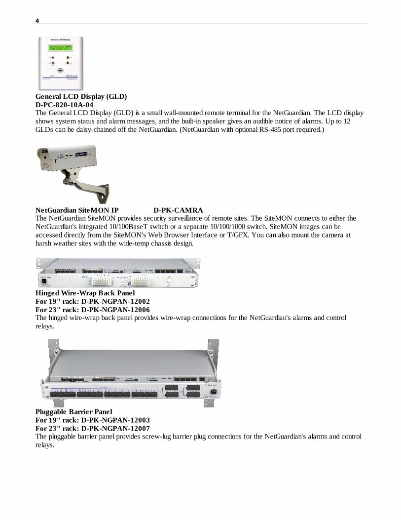
General LCD Display (GLD)D-PC-820-10A-04The General LCD Display (GLD) is a small wall-mounted remote terminal for the NetGuardian. The LCD displayshows system status and alarm messages, and the built-in speaker gives an audible notice of alarms. Up to 12GLDs can be daisy-chained off the NetGuardian. (NetGuardian with optional RS-485 port required.)
NetGuardian SiteMON IP D-PK-CAMRAThe NetGuardian SiteMON provides security surveillance of remote sites. The SiteMON connects to either theNetGuardian's integrated 10/100BaseT switch or a separate 10/100/1000 switch. SiteMON images can beaccessed directly from the SiteMON's Web Browser Interface or T/GFX. You can also mount the camera atharsh weather sites with the wide-temp chassis design.
Hinged Wire-Wrap Back PanelFor 19" rack: D-PK-NGPAN-12002For 23" rack: D-PK-NGPAN-12006The hinged wire-wrap back panel provides wire-wrap connections for the NetGuardian's alarms and controlrelays.
Pluggable Barrier PanelFor 19" rack: D-PK-NGPAN-12003For 23" rack: D-PK-NGPAN-12007The pluggable barrier panel provides screw-lug barrier plug connections for the NetGuardian's alarms and controlrelays.
5
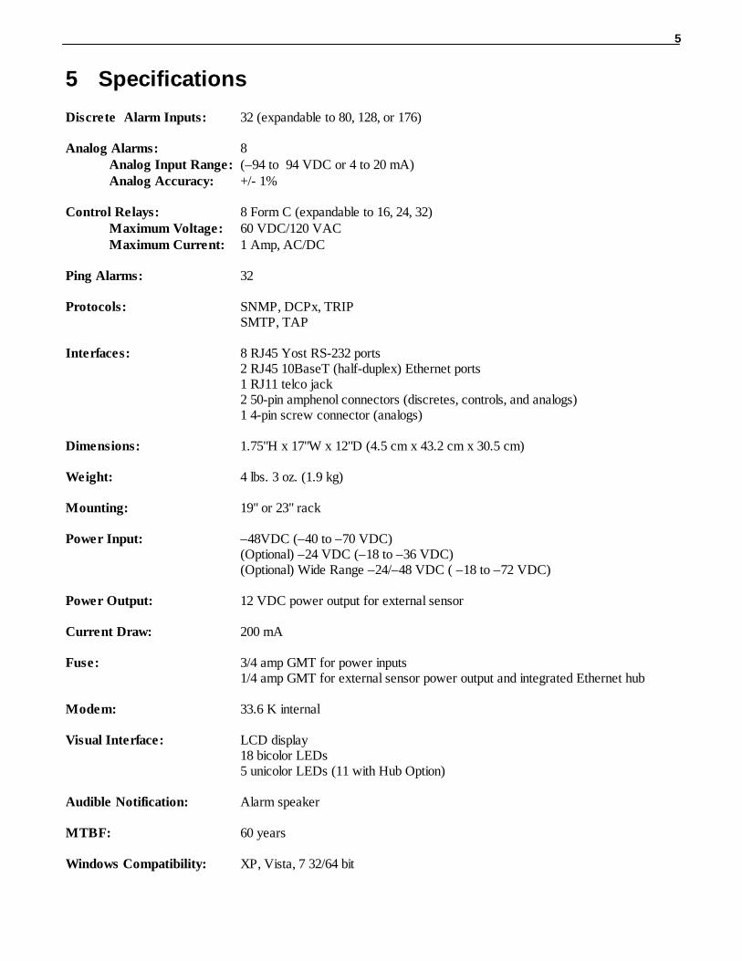
Specifications5
Discrete Alarm Inputs: 32 (expandable to 80, 128, or 176)
Analog Alarms: 8Analog Input Range: (–94 to 94 VDC or 4 to 20 mA)Analog Accuracy: +/- 1%
Control Relays: 8 Form C (expandable to 16, 24, 32)Maximum Voltage: 60 VDC/120 VACMaximum Current: 1 Amp, AC/DC
Ping Alarms: 32
Protocols: SNMP, DCPx, TRIPSMTP, TAP
Interfaces: 8 RJ45 Yost RS-232 ports2 RJ45 10BaseT (half-duplex) Ethernet ports1 RJ11 telco jack2 50-pin amphenol connectors (discretes, controls, and analogs)1 4-pin screw connector (analogs)
Dimensions: 1.75"H x 17"W x 12"D (4.5 cm x 43.2 cm x 30.5 cm)
Weight: 4 lbs. 3 oz. (1.9 kg)
Mounting: 19" or 23" rack
Power Input: –48VDC (–40 to –70 VDC)(Optional) –24 VDC (–18 to –36 VDC)(Optional) Wide Range –24/–48 VDC ( –18 to –72 VDC)
Power Output: 12 VDC power output for external sensor
Current Draw: 200 mA
Fuse: 3/4 amp GMT for power inputs1/4 amp GMT for external sensor power output and integrated Ethernet hub
Modem: 33.6 K internal
Visual Interface: LCD display18 bicolor LEDs5 unicolor LEDs (11 with Hub Option)
Audible Notification: Alarm speaker
MTBF: 60 years
Windows Compatibility: XP, Vista, 7 32/64 bit

6
Operating Temperature: 32°–140° F (0°–60° C)
Operating Humidity: 0%–95% noncondensing
RoHS 5 Approved
NEBS3 Compliant
7
Hardware Installation6
Tools Needed6.1
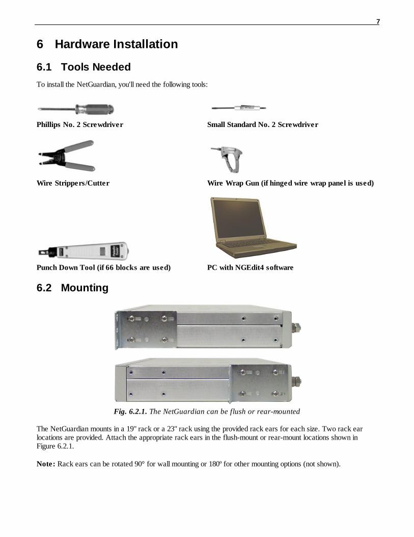
To install the NetGuardian, you'll need the following tools:
Phillips No. 2 Screwdriver Small Standard No. 2 Screwdriver
Wire Strippers/Cutter Wire Wrap Gun (if hinged wire wrap panel is used)
Punch Down Tool (if 66 blocks are used) PC with NGEdit4 software
Mounting6.2
Fig. 6.2.1. The NetGuardian can be flush or rear-mounted
The NetGuardian mounts in a 19" rack or a 23" rack using the provided rack ears for each size. Two rack earlocations are provided. Attach the appropriate rack ears in the flush-mount or rear-mount locations shown inFigure 6.2.1.
Note: Rack ears can be rotated 90° for wall mounting or 180º for other mounting options (not shown).
8
Power Connection6.3
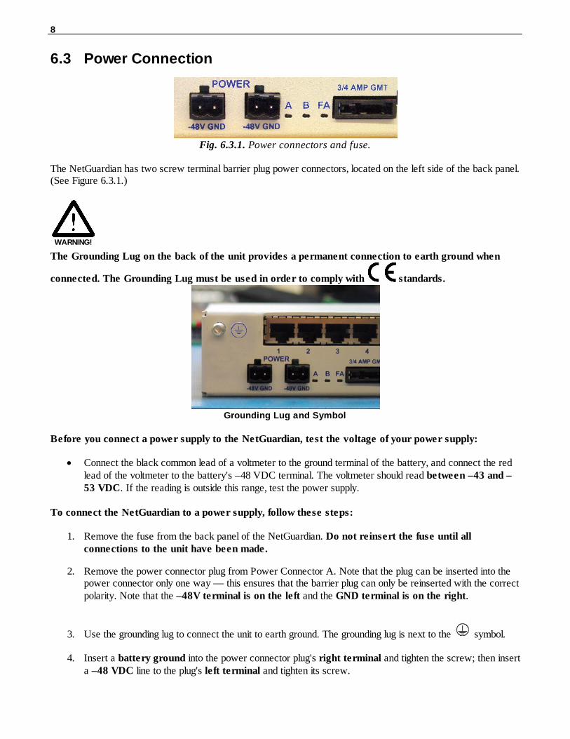
Fig. 6.3.1. Power connectors and fuse.
The NetGuardian has two screw terminal barrier plug power connectors, located on the left side of the back panel.(See Figure 6.3.1.)
WARNING!
The Grounding Lug on the back of the unit provides a permanent connection to earth ground when
connected. The Grounding Lug must be used in order to comply with standards.
Grounding Lug and Symbol
Before you connect a power supply to the NetGuardian, test the voltage of your power supply:
· Connect the black common lead of a voltmeter to the ground terminal of the battery, and connect the redlead of the voltmeter to the battery's –48 VDC terminal. The voltmeter should read between –43 and –53 VDC. If the reading is outside this range, test the power supply.
To connect the NetGuardian to a power supply, follow these steps:
1. Remove the fuse from the back panel of the NetGuardian. Do not reinsert the fuse until allconnections to the unit have been made.
2. Remove the power connector plug from Power Connector A. Note that the plug can be inserted into thepower connector only one way — this ensures that the barrier plug can only be reinserted with the correctpolarity. Note that the –48V terminal is on the left and the GND terminal is on the right.
3. Use the grounding lug to connect the unit to earth ground. The grounding lug is next to the symbol.
4. Insert a battery ground into the power connector plug's right terminal and tighten the screw; then inserta –48 VDC line to the plug's left terminal and tighten its screw.

9
5. Push the power connector plug firmly back into the power connector. If the power feed is connectedcorrectly, the LED by the connector will light GREEN. If the polarity of the power feed is reversed, theLED will not illuminate.
6. Repeat Steps 2–4 for Power Connector B.
7. Reinsert the fuse to power the NetGuardian. The front panel LEDs will flash RED and GREEN.

10
To connect the NetGuardian to a power supply using a WAGO connector, follow these steps:
WARNING!
The Grounding Lug on the back of the unit provides a permanent connection to earth ground when
connected. The Grounding Lug must be used in order to comply with standards.
Grounding Lug and Symbol
1. Remove the 2 fuses (A& B) from the back panel of the NetGuardian. Do not reinsert the fuses until allconnections to the unit have been made.
2. Remove the WAGO power connector. Note that the plug can be inserted into the power connector only oneway — this ensures that the barrier plug can only be reinserted with the correct polarity. Note that the –48Vterminal is on Slots 1 and 3 and the GND terminal is on Slots 2 and 4.
3. Use the grounding lug to connect the unit to earth ground. The grounding lug is next to the symbol.
4. Insert a battery ground into the power connector plug's slots 2 and 4 by pushing down on top of theappropriate slot of the WAGO connector with a screwdriver and inserting the wire into the slot, then releasing thescrewdriver. Insert a –48 VDC line to the plug's slots 1 and 3 using the same method as before.

11
Inserting a -48 VDC Line into Slot 1 of WAGO Connector
5. Push the power connector plug firmly back into the power connector. If the power feed is connected correctly,the LED by the connector will light GREEN. If the polarity of the power feed is reversed, the LED will notilluminate.
6. Reinsert the fuses to power the NetGuardian. The front panel LEDs will flash RED and GREEN.

12
LAN Connection6.4
Fig. 6.4.1. Ethernet ports
For enhanced security, the NetGuardian 832A has two 10BaseT Ethernet ports. Each port has its own separate IPaddress and subnet, so you can safely connect one port to your private company LAN and the other to the publicInternet.
By default, outbound data traffic from the NetGuardian 832A will be sent over Net 2. Only outbound data that isspecifically directed to Net 1, usually the Company's LAN, will be sent to Net 1.
Both ports are standard RJ45 ports that take standard RJ45 Ethernet cables. If the IP connection is OK, the LNKLED will light SOLID GREEN when the cable is connected.
RJ45 Ethernet Connection
8
7
56 Receive In– (RI–)
43 Receive In + (RI+)
2 Transmit Out– (TO–)1 Transmit Out + (TO+)
Fig. 6.4.2 Ethernet port pinout
The pinout for the Ethernet ports is shown in Figure 6.4.2, above.
NOTE: There is no routing between Net 1 and Net 2, this ensures that both connections are independent of eachother.
Telco Connection6.5
Fig. 6.5.1. Telco jack
The rear panel telco jack (see Figure 6.5.1) connects the NetGuardian internal modem to a standard phone line fordial-up access and pager alarm notification.

13
4
3 Ring
2 Tip
1
RJ11 Phone Line Connection
Fig. 6.5.2 Telco jack pinout
The pinout for the Telco jack is shown in Figure 6.5.2, above.
Alarm and Control Relay Connections6.6
Fig. 6.6.1. Alarm and control relay connectors
The NetGuardian's discrete alarm inputs, control relay outputs, and first six analog alarm inputs are connectedthrough the two 50-pin connectors labeled "Discretes 1–24" and "Analogs 1–6/Discretes 25–32/Relays 1–8" on theback panel. Analog alarm inputs 7 and 8 are connected through the four-pin connector labeled "Analogs 7–8." (SeeFigure 6.6.1.)
6.6.1 Alarm and Control Relay Connector Pinout Table
Discretes 1–25
RTN ALM RTN ALM
ALM 1 1 26 ALM 13 13 38
ALM 2 2 27 ALM 14 14 39
ALM 3 3 28 ALM 15 15 40
ALM 4 4 29 ALM 16 16 41
ALM 5 5 30 ALM 17 17 42
ALM 6 6 31 ALM 18 18 43
ALM 7 7 32 ALM 19 19 44
ALM 8 8 33 ALM 20 20 45
ALM 9 9 34 ALM 21 21 46
ALM 10 10 35 ALM 22 22 47
ALM 11 11 36 ALM 23 23 48
ALM 12 12 37 ALM 24 24 49
GND 25 50
Discretes 25–32
RTN ALM
ALM 25 1 26
ALM 26 2 27
ALM 27 3 28
ALM 28 4 29
ALM 29 5 30
ALM 30 6 31
ALM 31 7 32
ALM 32 8 33
Control Relays 1–8
NO/NC CO
CTRL 1 9 34
CTRL 2 10 35
CTRL 3 11 36
CTRL 4 12 37
CTRL 5 13 38
CTRL 6 14 39
CTRL 7 15 40
CTRL 8 16 41
FUSE 17 42
Analogs 1–6
+ –
Analogs 7–8
+ –

14
ANA 1 19 44
ANA 2 20 45
ANA 3 21 46
ANA 4 22 47
ANA 5 23 48
ANA 6 24 49
GND 25 50
ANA 7 7+ 7-
ANA 8 8+ 8-
Analogs 7–8
ANA 7 + ANA 8–
ANA 7– ANA 8 +
Table 6.6.1.A. Alarm and control relay connector pinout
Table 6.6.1.A shows the pinouts for the 50-pin connectors "Discretes 1–24" and "Analogs 1–6/Discretes 25–32/Relays 1–8," and the pinout for the four-pin connector "Analogs 7–8."
Note that the NetGuardian's control relays can be set for either Normally Open or Normally Closed operation. Byfactory default, all control relays are set to Normally Open. You can reset all relays for Normally Closed operationat the hardware level by resetting a jumper on the NetGuardian circuit board. You can also configure the controlrelays individually, using either the Web interface or the NGEdit4 software utility.
For instructions on resetting control relays for Normally Closed operation, see Section 6.12, "Jumper Options."
15
6.6.2 Discretes 1–24 Connector Pinout Diagram
123456789
10111213141516171819202122232425
26272829303132333435363738394041424344454647484950
RTN 1RTN 2RTN 3RTN 4RTN 5RTN 6RTN 7RTN 8RTN 9RTN 10RTN 11RTN 12RTN 13RTN 14RTN 15RTN 16
GND
RTN 17 ALM 17ALM 18ALM 19ALM 20ALM 21ALM 22ALM 23ALM 24
GND
RTN 18RTN 19RTN 20RTN 21RTN 22RTN 23RTN 24
ALM 1ALM 2ALM 3ALM 4ALM 5ALM 6ALM 7ALM 8ALM 9
ALM 10ALM 11ALM 12ALM 13ALM 14ALM 15ALM 16
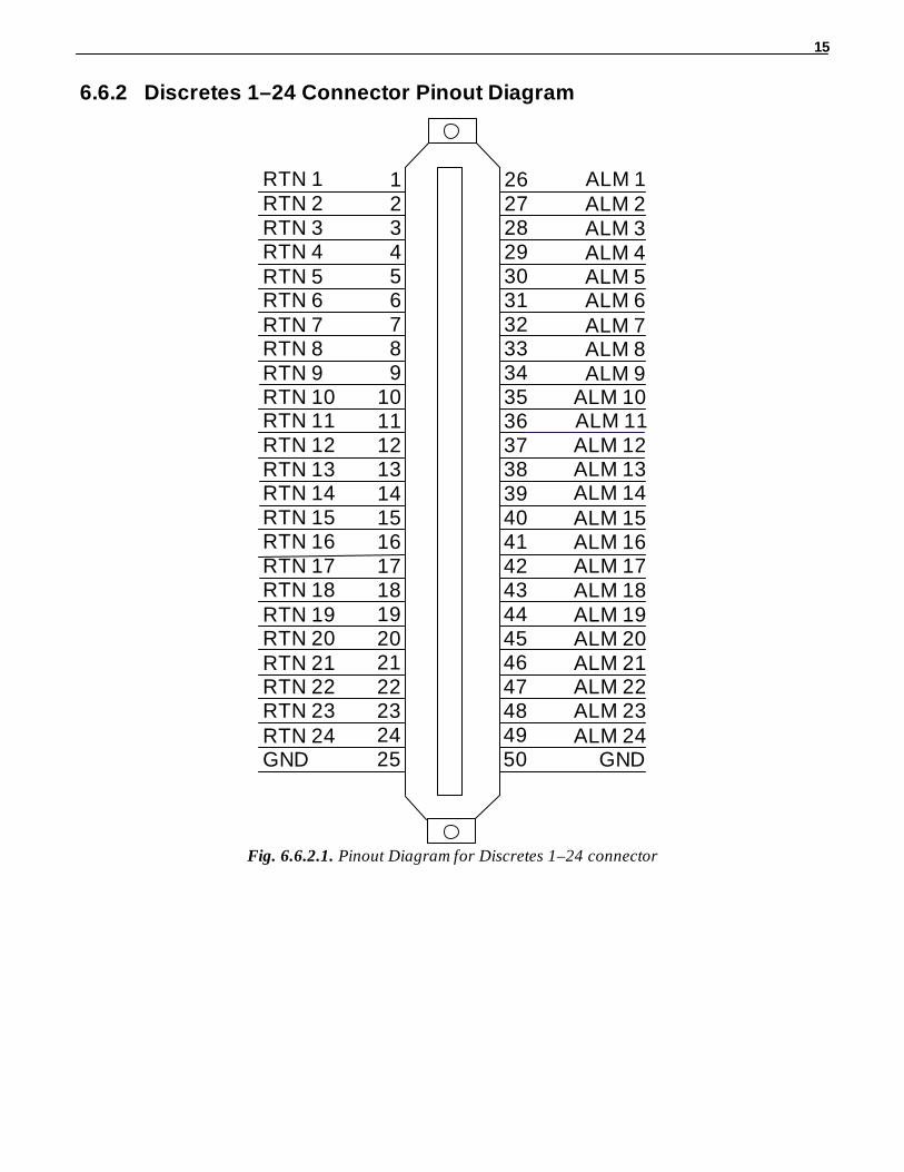
Fig. 6.6.2.1. Pinout Diagram for Discretes 1–24 connector

16
6.6.3 Analogs1–6/Discretes 25–32/Relays 1–8 Connector PinoutDiagram
123456789
10111213141516171819202122232425
26272829303132333435363738394041424344454647484950
RTN 25RTN 26RTN 27RTN 28RTN 29RTN 30RTN 31RTN 32CTRL 1 NOCTRL 2 NOCTRL 3 NOCTRL 4 NOCTRL 5 NOCTRL 6 NOCTRL 7 NOCTRL 8 NO
GND
FUSE NO FUSE COUnusedANA 1 –ANA 2 –ANA 3 –ANA 4 –ANA 5 –ANA 6 –
GND
UnusedANA 1 +ANA 2 +ANA 3 +ANA 4 +ANA 5 +ANA 6 +
ALM 25ALM 26ALM 27ALM 28ALM 29ALM 30ALM 31ALM 32
CTRL 1 COCTRL 2 COCTRL 3 COCTRL 4 COCTRL 5 COCTRL 6 COCTRL 7 COCTRL 8 CO
Fig. 6.6.3.1. Pinout Diagram for Discretes 25–32/Relays 1–8 connector
17
6.6.4 Analogs 7–8 Connector
Analogs 7 –8
ANA 7 + ANA 8 –
ANA 7 – ANA 8 +
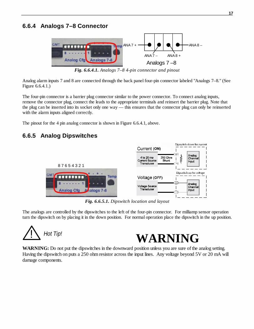
Fig. 6.6.4.1. Analogs 7–8 4-pin connector and pinout
Analog alarm inputs 7 and 8 are connected through the back panel four-pin connector labeled "Analogs 7–8." (SeeFigure 6.6.4.1.)
The four-pin connector is a barrier plug connector similar to the power connector. To connect analog inputs,remove the connector plug, connect the leads to the appropriate terminals and reinsert the barrier plug. Note thatthe plug can be inserted into its socket only one way — this ensures that the connector plug can only be reinsertedwith the alarm inputs aligned correctly.
The pinout for the 4 pin analog connector is shown in Figure 6.6.4.1, above.
6.6.5 Analog Dipswitches
8 7 6 5 4 3 2 1
Fig. 6.6.5.1. Dipswitch location and layout
The analogs are controlled by the dipswitches to the left of the four-pin connector. For milliamp sensor operationturn the dipswitch on by placing it in the down position. For normal operation place the dipswitch in the up position.
! Hot Tip! WARNING
WARNING: Do not put the dipswitches in the downward position unless you are sure of the analog setting. Having the dipswitch on puts a 250 ohm resistor across the input lines. Any voltage beyond 5V or 20 mA willdamage components.
18
6.6.6 Integrated Temperature and Battery Sensor (Optional)
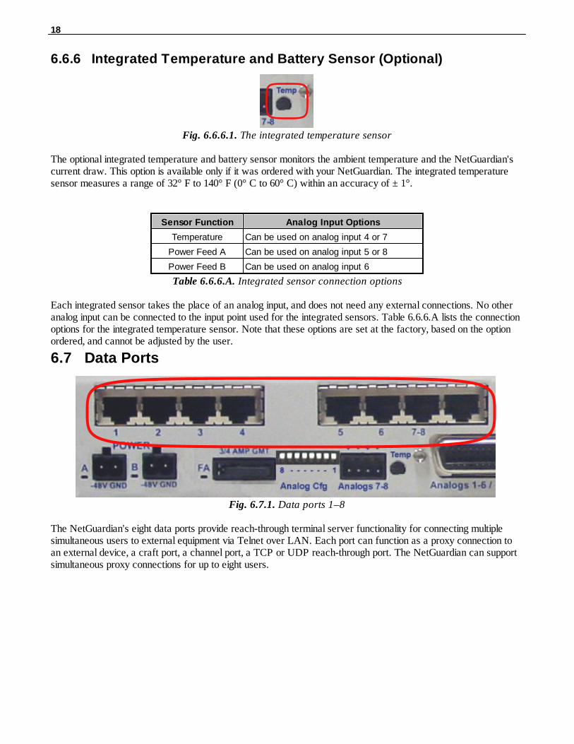
Fig. 6.6.6.1. The integrated temperature sensor
The optional integrated temperature and battery sensor monitors the ambient temperature and the NetGuardian'scurrent draw. This option is available only if it was ordered with your NetGuardian. The integrated temperaturesensor measures a range of 32° F to 140° F (0° C to 60° C) within an accuracy of ± 1°.
Sensor Function Analog Input Options
Temperature Can be used on analog input 4 or 7
Power Feed A Can be used on analog input 5 or 8
Power Feed B Can be used on analog input 6
Table 6.6.6.A. Integrated sensor connection options
Each integrated sensor takes the place of an analog input, and does not need any external connections. No otheranalog input can be connected to the input point used for the integrated sensors. Table 6.6.6.A lists the connectionoptions for the integrated temperature sensor. Note that these options are set at the factory, based on the optionordered, and cannot be adjusted by the user.
Data Ports6.7
Fig. 6.7.1. Data ports 1–8
The NetGuardian's eight data ports provide reach-through terminal server functionality for connecting multiplesimultaneous users to external equipment via Telnet over LAN. Each port can function as a proxy connection toan external device, a craft port, a channel port, a TCP or UDP reach-through port. The NetGuardian can supportsimultaneous proxy connections for up to eight users.
19
1 TX+ (Transmit +)
2 N/C (Not Connected)3 RX+ (Receive +)4 N/C (Not Connected)5 N/C (Not Connected)6 RX- (Receive -)7 N/C (Not Connected)8 TX- (Transmit -)
Yost RS-485 RJ45 Connector
1 CTS (Clear to Send)
2 DSR (Data Set Ready)3 RXD (Receive Data)4 GND (Ground)5 GND (Ground)6 TXD (Transmit Data)7 DTR (Data Terminal Ready)8 RTS (Request to Send)
Yost RS-232 RJ45 Connector
1 TX- (Transmit -)
2 N/C (Not Connected)3 RX+ (Receive +)4 N/C (Not Connected)5 N/C (Not Connected)6 RX- (Receive -)7 N/C (Not Connected)8 TX+ (Transmit +)
Yost 4-Wire 202 Connector
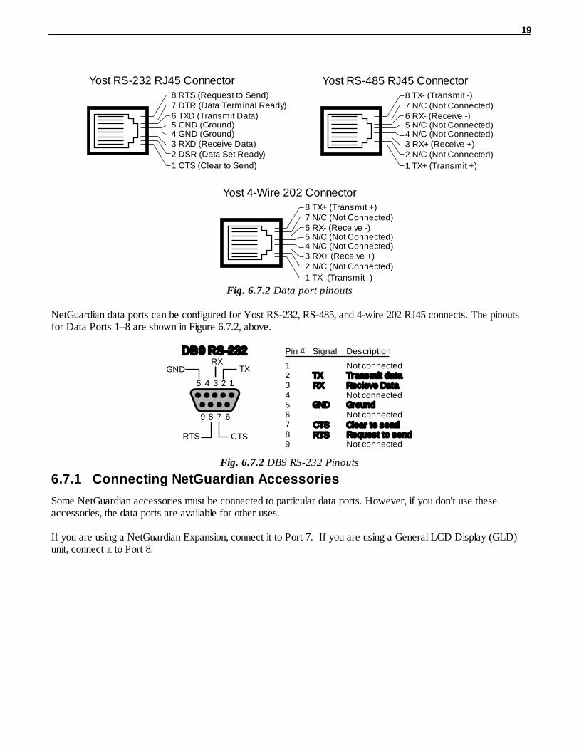
Fig. 6.7.2 Data port pinouts
NetGuardian data ports can be configured for Yost RS-232, RS-485, and 4-wire 202 RJ45 connects. The pinoutsfor Data Ports 1–8 are shown in Figure 6.7.2, above.
12345
TXGND
6789
CTS
Pin # Signal Description
1 Not connected2 TX Transmit data345 GND Ground6 Not connected7 CTS Clear to send89 Not connected
Recieve DataNot connected
Request to send
DB9 RS-232
RTS
RX
RTS
RX
Fig. 6.7.2 DB9 RS-232 Pinouts
6.7.1 Connecting NetGuardian Accessories
Some NetGuardian accessories must be connected to particular data ports. However, if you don't use theseaccessories, the data ports are available for other uses.
If you are using a NetGuardian Expansion, connect it to Port 7. If you are using a General LCD Display (GLD)unit, connect it to Port 8.

20
Integrated 10BaseT Ethernet Hub (Optional)6.8
RegularEthernet
PortsUplink/Crossover
Port
Hub ComStatus LEDs
¼ Fuse for HubPower Supply
Fig. 6.8.1. NetGuardian integrated Ethernet Hub
You can order your NetGuardian 832A with an optional integrated Ethernet hub, which provides four regularEthernet ports and one uplink or crossover Ethernet port. (See Figure 6.8.1.). The integrated Ethernet hub ispowered by the same –48 VDC power as the NetGuardian, which provides more secure, more robust operationthan hubs that run off commercial power. The integrated hub also frees valuable rack space by eliminating anunnecessary extra unit.
To power and activate the integrated Ethernet hub, insert the provided 1/4 amp fuse in the hub's fusesocket. (See Figure 6.8.1.) If you ever want to turn off power to the integrated hub, just remove the fuse.
21
RJ45 Ethernet Connection
8
7
56 Trasmit Out – (TO–)
43 Transmit Out + (TO+)
2 Receive In – (RI–)1 Receive In + (RI+)
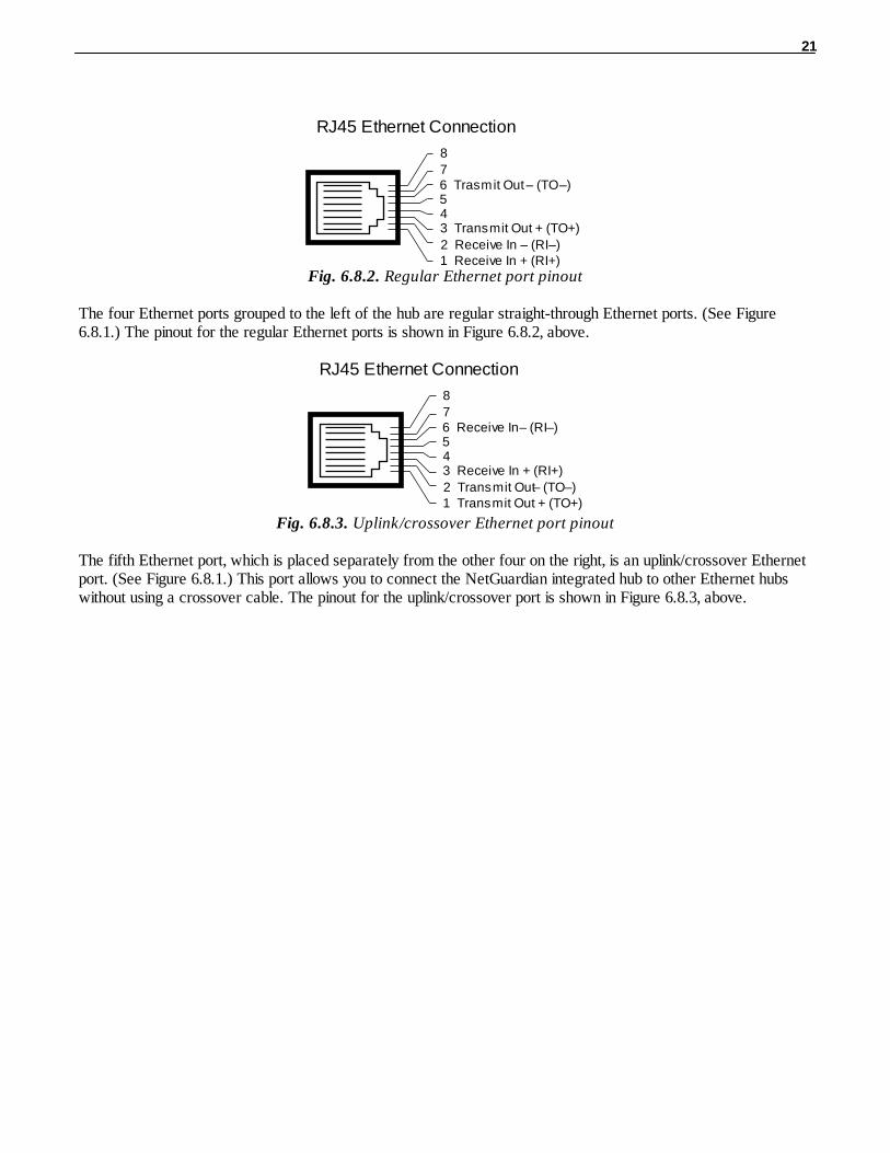
Fig. 6.8.2. Regular Ethernet port pinout
The four Ethernet ports grouped to the left of the hub are regular straight-through Ethernet ports. (See Figure6.8.1.) The pinout for the regular Ethernet ports is shown in Figure 6.8.2, above.
RJ45 Ethernet Connection
8
7
56 Receive In– (RI–)
43 Receive In + (RI+)
2 Transmit Out– (TO–)1 Transmit Out + (TO+)
Fig. 6.8.3. Uplink/crossover Ethernet port pinout
The fifth Ethernet port, which is placed separately from the other four on the right, is an uplink/crossover Ethernetport. (See Figure 6.8.1.) This port allows you to connect the NetGuardian integrated hub to other Ethernet hubswithout using a crossover cable. The pinout for the uplink/crossover port is shown in Figure 6.8.3, above.

22
+12 VDC Sensor Power Supply6.9
Fig. 6.9.1. +12 VDC sensor power supply
You can order your NetGuardian 832A with an optional +12 VDC sensor power supply. (See Figure 6.9.1.) Thisprovides a convenient way to connect an auxiliary sensor to a robust battery power supply.
The two-pin connector for the sensor power supply is a barrier plug connector similar to the main powerconnector.
To power an external sensor, follow these steps:
1. Remove the 1/4 amp fuse from the sensor power supply on the back panel of the NetGuardian. (SeeFigure 6.9.1.) Do not reinsert the fuse until all power connections to the external sensor havebeen made.
2. Remove the power connector plug from the sensor power supply. Note that the plug can be inserted intothe power connector only one way — this ensures that the barrier plug can only be reinserted with thecorrect polarity. Note that the positive terminal is on the left and the negative terminal is on theright.
3. Connect the appropriate leads to each of the plug's screw terminals and tighten the screws.
4. Push the power connector plug firmly back into the sensor power supply connector.
5. Reinsert the fuse to power the external sensor.
23
Optional 66 Block Connector6.10
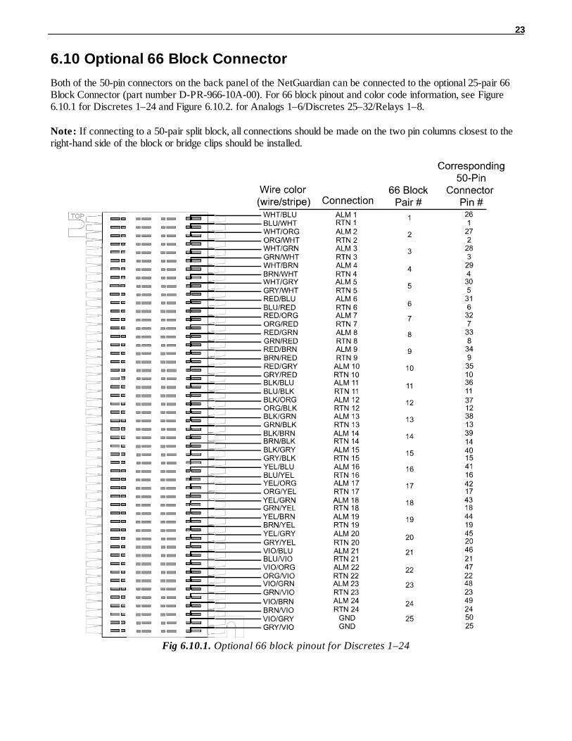
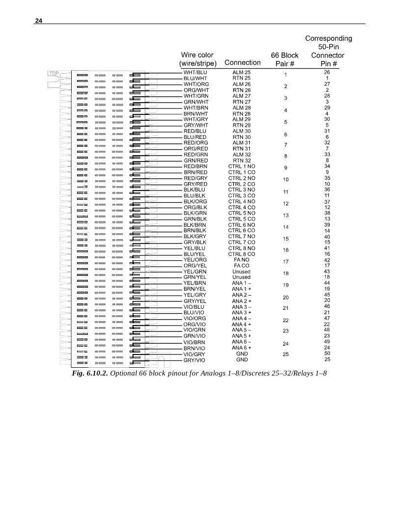
Both of the 50-pin connectors on the back panel of the NetGuardian can be connected to the optional 25-pair 66Block Connector (part number D-PR-966-10A-00). For 66 block pinout and color code information, see Figure6.10.1 for Discretes 1–24 and Figure 6.10.2. for Analogs 1–6/Discretes 25–32/Relays 1–8.
Note: If connecting to a 50-pair split block, all connections should be made on the two pin columns closest to theright-hand side of the block or bridge clips should be installed.
Fig 6.10.1. Optional 66 block pinout for Discretes 1–24
24
Fig. 6.10.2. Optional 66 block pinout for Analogs 1–8/Discretes 25–32/Relays 1–8
25
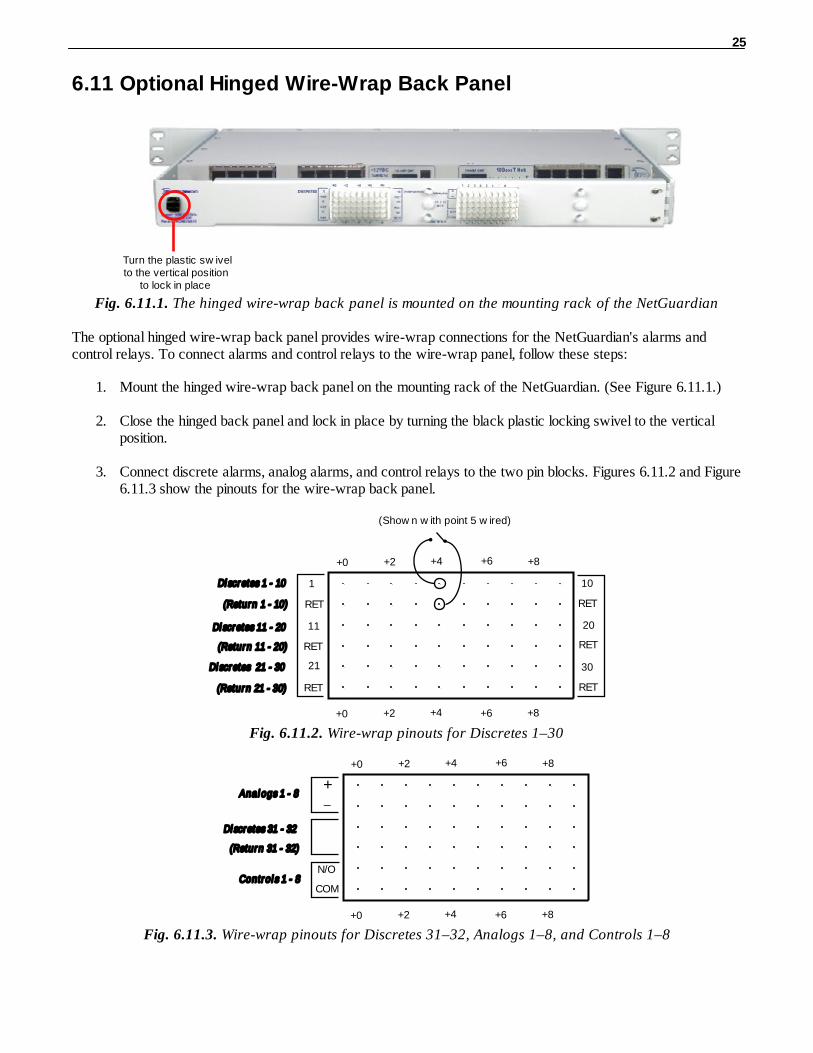
Optional Hinged Wire-Wrap Back Panel6.11
Turn the plastic sw ivelto the vertical position
to lock in place
Fig. 6.11.1. The hinged wire-wrap back panel is mounted on the mounting rack of the NetGuardian
The optional hinged wire-wrap back panel provides wire-wrap connections for the NetGuardian's alarms andcontrol relays. To connect alarms and control relays to the wire-wrap panel, follow these steps:
1. Mount the hinged wire-wrap back panel on the mounting rack of the NetGuardian. (See Figure 6.11.1.)
2. Close the hinged back panel and lock in place by turning the black plastic locking swivel to the verticalposition.
3. Connect discrete alarms, analog alarms, and control relays to the two pin blocks. Figures 6.11.2 and Figure6.11.3 show the pinouts for the wire-wrap back panel.
+0 +2 +4 +6 +8
Di scretes 1 - 10 1
RET
11
RET
21
RET
10
RET
20
RET
30
RET
+0 +2 +4 +6 +8
Di scretes 11 - 20
Di scretes 21 - 30
(Return 1 - 10)
(Return 11 - 20)
(Return 21 - 30)
(Show n w ith point 5 w ired)
Fig. 6.11.2. Wire-wrap pinouts for Discretes 1–30
+0 +2 +4 +6 +8
Anal ogs 1 - 8+ _
+0 +2 +4 +6 +8
Di scretes 31 - 32
Control s 1 - 8
(Return 31 - 32)
N/O
COM
Fig. 6.11.3. Wire-wrap pinouts for Discretes 31–32, Analogs 1–8, and Controls 1–8

26
6.11.1 Lexan Wire-Wrap Cover
Lexan panel bracket
Lexan panel
Spacer
Securing screw
Fig. 6.11.1.1. Lexan panel assembly
To attach the Lexan cover to the hinged wire-wrap panel, follow these steps:
1. Attach communication lines to the wire-wrap pins before connecting the Lexan cover
2. Attach the Lexan cover to the mounting clips and connect to the hinged panel. (See Figure 6.11.1.1.)

27
Jumper Options6.12
Control RelayJumpers
Fig. 6.12.1. Adjustable jumpers on the NetGuardian circuit board
The following options are adjusted by resetting jumpers on the NetGuardian's circuit board:
· Control relays can be switched from normally open (N/O) to normally closed (N/C)
To open the unit and expose the circuit board, remove the screws from the top of the NetGuardian and lift the topcover off. Figure 6.12.1 shows the circuit board and the location of the adjustable jumpers.
WARNING: Always observe anti-static precautions whenever opening the unit.

28
Normally Open Position Normally Closed Position
Control Point Detail1A 1B
N.C. Jumper
N.O. Jumper
N.C.
N.O.
Fig. 6.12.2. Jumper settings for analog alarm inputs and control relays
By default, all the adjustable jumpers are open, except for the speaker jumper. For control relay jumpers, the openposition corresponds to normally open operation, and the closed position corresponds to normally closed operation.See Figure 6.12.2. and Refer to Table 6.12.A for default jumper settings and descriptions.
Note: Default settings may be different if you ordered a special configuration NetGuardian.
Jumper Description
J16 / RLY1 Control Relay 1
J17 / RLY2 Control Relay 2
J19 / RLY3 Control Relay 3
J20 / RLY4 Control Relay 4
J18 / RLY5 Control Relay 5
J22 / RLY6 Control Relay 6
J23 / RLY7 Control Relay 7
J24 / RLY8 Control Relay 8
Table 6.12.A. Jumper descriptions and settings
LCD Display7
Fig. 7.1. NetGuardian LCD showing the Standard Prompt
The front panel LCD displays the current alarm and control status and provides a command menu for controllingthe NetGuardian's basic functions.
Using the LCD command menuThe four buttons surrounding the front panel LCD are used to access the LCD Command Menu. To access themenu, press the Menu button. To scroll the menu, use the q and p buttons. To select a menu command, press theSel (Select) button.
Standard Prompt

29
When no Command Menu item is selected and no alarms or relays are active, the LCD displays the firmwareversion and the standard prompt, Press MENU for front panel options.
Controlling Display SpeedThe scroll speed can be temporarily increased by pressing and holding the p button while the message is active.
Alarm and Control Status Messages7.1
If an alarm or control relay is active, the LCD will display the following messages to indicate alarm and controlstatus:
The LCD panel will display the following messages to indicate alarm and control status:
Discrete Alarms: If there are any standing discrete alarms, the display will read "Discrete Alarms:",followed by the user-defined descriptions of the standing alarm points.
Relays: If there are any latched relays, the display will read "Relays:", followed by theuser-defined descriptions of the latched relays.
Ping Alarms: If any ping targets have failed to respond within the specified time, the display willread "Ping Alarms:", followed by the user-defined descriptions of the ping targets.
Analogs: If any analog channels have crossed a threshold value, the display will read"Analogs", followed by the user-defined description of the analog channel, thechannel's last voltage reading, and a letter indicating which threshold the channelhas crossed.
Analog thresholds are represented by the following characters:
Major Over: a capital OMinor Over: a lower-case oMinor Under: a lower-case uMajor Under: a capital U
LCD Command Menu7.2
Fig. 7.3.1. LCD display, showing the Standard Prompt
The LCD Command Menu provides commands for controlling some of the NetGuardian's basic functions:temporarily silencing the alarm speaker, rebooting the unit, and running the TTY configuration utility.
When no Command Menu item is selected and no alarms or relays are active, the LCD displays the firmwareversion and the Standard Prompt, Press MENU for front panel options. (See Figure 7.3.1, above.)
To access the Command Menu, press the Menu button.

30
7.2.1 Sound off
Fig. 7.3.1.1. Sound Off command
Sound offThe Sound off command suppresses sounds from the alarm speaker for a user-defined period of 10, 20, or 30minutes.
To scroll to the next menu command, press the q button.
To change the Sound off setting, press Sel to select the command. The arrow cursor (>) will move to the rightof the colon (:) in Sound off: to indicate that the command submenu is selected. Press the q and p buttons to scrollthrough the Sound off time period options. Select 0 minutes to allow all sounds. When the time period you want isdisplayed, press Sel to make your selection.
To exit the Command Menu without changing the Sound off setting, press Menu.
7.2.2 Reboot
Fig. 7.3.2.1. Reboot command
RebootThe Reboot command reboots the NetGuardian.
To scroll to the next menu command, press the q button.
To reboot the NetGuardian, press Sel. The LCD will briefly display the message Rebooting ..., and the normalboot sequence will begin.
To exit the Command Menu without rebooting, press Menu.
31
7.2.3 Run Config
Fig. 7.3.3.1. Run Config command
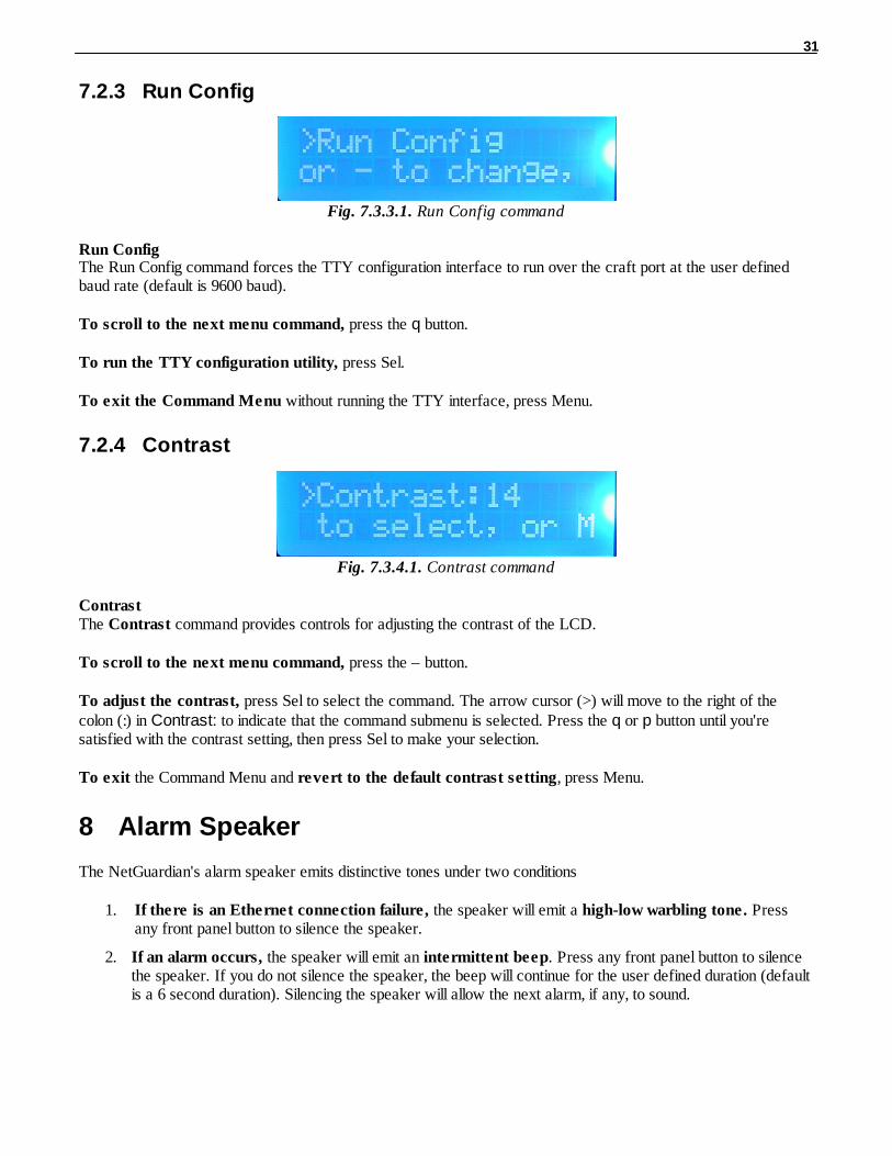
Run ConfigThe Run Config command forces the TTY configuration interface to run over the craft port at the user definedbaud rate (default is 9600 baud).
To scroll to the next menu command, press the q button.
To run the TTY configuration utility, press Sel.
To exit the Command Menu without running the TTY interface, press Menu.
7.2.4 Contrast
Fig. 7.3.4.1. Contrast command
ContrastThe Contrast command provides controls for adjusting the contrast of the LCD.
To scroll to the next menu command, press the – button.
To adjust the contrast, press Sel to select the command. The arrow cursor (>) will move to the right of thecolon (:) in Contrast: to indicate that the command submenu is selected. Press the q or p button until you'resatisfied with the contrast setting, then press Sel to make your selection.
To exit the Command Menu and revert to the default contrast setting, press Menu.
Alarm Speaker8
The NetGuardian's alarm speaker emits distinctive tones under two conditions
1. If there is an Ethernet connection failure, the speaker will emit a high-low warbling tone. Pressany front panel button to silence the speaker.
2. If an alarm occurs, the speaker will emit an intermittent beep. Press any front panel button to silencethe speaker. If you do not silence the speaker, the beep will continue for the user defined duration (defaultis a 6 second duration). Silencing the speaker will allow the next alarm, if any, to sound.

32
Front Panel LEDs9
Fig. 9.1. Front panel LEDs
The NetGuardian's front panel LEDs indicate communication and alarm reporting status. LED status messagesare described below in Table 9.A.
LED Status Description
Modem Solid Red Modem Initializing or in use
Alarm Blink Red New COS alarm*
Solid Red One or more standing alarms*
Config Blink Green Valid configuration
Blink Red Invalid configuration
Net 1 Blink Green Transmit over Ethernet port 1
Blink Red Receive over Ethernet port 1
Net 2 Blink Green Transmit over Ethernet port 2
Blink Red Receive over Ethernet port 2
LNK Alarm Solid Red No Ethernet link detected (for configured Net 1 or Net 2)
Craft Blink Green Transmit over craft port
Blink Red Receive over craft port
Modem Blink Green Transmit over Modem port
Blink Red Receive over Modem port
Data Ports1-8
Blink Green Transmit over indicated data port
Blink Red Receive over indicated data port
*NO TE: Alarm must be configured for notification to be reflected in LED
Table 9.A. Front panel LED Status message descriptions
33
Back Panel LEDs10
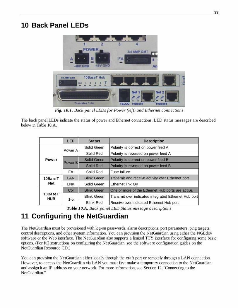
Fig. 10.1. Back panel LEDs for Power (left) and Ethernet connections
The back panel LEDs indicate the status of power and Ethernet connections. LED status messages are describedbelow in Table 10.A.
LED Status Description
Power
Power ASolid Green Polarity is correct on power feed A
Solid Red Polarity is reversed on power feed A
Power BSolid Green Polarity is correct on power feed B
Solid Red Polarity is reversed on power feed B
FA Solid Red Fuse failure
10BaseTNet
LAN Blink Green Transmit and receive activity over Ethernet port
LNK Solid Green Ethernet link OK
10BaseTHUB
Col Blink Green One or more of the Ethernet Hub ports are active.
1-5Blink Green Transmit over indicated integrated Ethernet Hub port
Blink Red Receive over indicated Ethernet Hub port
Table 10.A. Back panel LED Status message descriptions
Configuring the NetGuardian11
The NetGuardian must be provisioned with log-on passwords, alarm descriptions, port parameters, ping targets,control descriptions, and other system information. You can provision the NetGuardian using either the NGEdit4software or the Web interface. The NetGuardian also supports a limited TTY interface for configuring some basicoptions. (For full instructions on configuring the NetGuardian, see the software configuration guides on theNetGuardian Resource CD.)
You can provision the NetGuardian either locally through the craft port or remotely through a LAN connection.However, to access the NetGuardian via LAN you must first make a temporary connection to the NetGuardianand assign it an IP address on your network. For more information, see Section 12, "Connecting to theNetGuardian."
34
Connecting to the NetGuardian12
... via Craft Port12.1
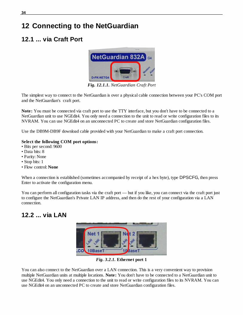
Fig. 12.1.1. NetGuardian Craft Port
The simplest way to connect to the NetGuardian is over a physical cable connection between your PC's COM portand the NetGuardian's craft port.
Note: You must be connected via craft port to use the TTY interface, but you don't have to be connected to aNetGuardian unit to use NGEdit4. You only need a connection to the unit to read or write configuration files to itsNVRAM. You can use NGEdit4 on an unconnected PC to create and store NetGuardian configuration files.
Use the DB9M-DB9F download cable provided with your NetGuardian to make a craft port connection.
Select the following COM port options:• Bits per second: 9600• Data bits: 8• Parity: None• Stop bits: 1• Flow control: None
When a connection is established (sometimes accompanied by receipt of a hex byte), type DPSCFG, then pressEnter to activate the configuration menu.
You can perform all configuration tasks via the craft port — but if you like, you can connect via the craft port justto configure the NetGuardian's Private LAN IP address, and then do the rest of your configuration via a LANconnection.
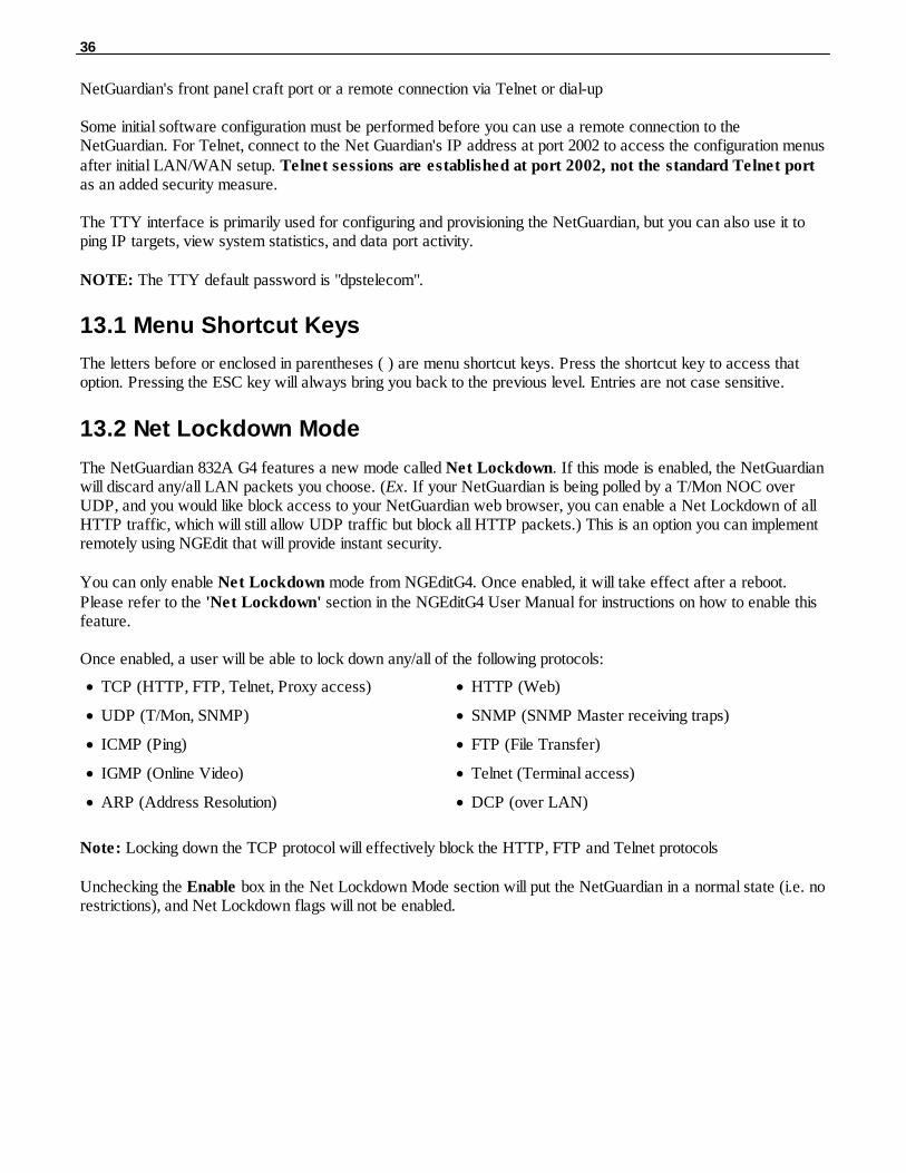
... via LAN12.2
Fig. 3.2.1. Ethernet port 1
You can also connect to the NetGuardian over a LAN connection. This is a very convenient way to provisionmultiple NetGuardian units at multiple locations. Note: You don't have to be connected to a NetGuardian unit touse NGEdit4. You only need a connection to the unit to read or write configuration files to its NVRAM. You canuse NGEdit4 on an unconnected PC to create and store NetGuardian configuration files.

35
To connect to the NetGuardian via LAN, all you need is the unit's IP address (Default IP address is192.168.1.100).
If you have physical access to the NetGuardian, the easiest thing to do is connect to the unit through the craftport and then assign it an IP address. Then you can complete the rest of the unit configuration over a remote LANconnection, if you want. For instructions, see Section 12.1, "Connecting to the NetGuardian via Craft Port."
If you DON'T have physical access to the NetGuardian, you can make a LAN connection to the unit bytemporarily changing your PC's IP address and subnet mask to match the NetGuardian's factory default IPsettings. Follow these steps:
1. Look up your PC's current IP address and subnet mask, and write this information down. 2. Reset your PC's IP address to 192.168.1.200. 3. Reset your PC's subnet mask to 255.255.0.0. You may have to reboot your PC to apply your changes. 4. Once the IP address and subnet mask of your computer coincide with the NetGuardian's, you can access
the NetGuardian via a Telnet session or via Web browser by using the NetGuardian's default IP addressof 192.168.1.100.
5. Provision the NetGuardian with the appropriate information, then change your computer's IP address andsubnet mask back to their original settings.
TTY Interface13
Fig. 13.1. The TTY interface initial configuration screen
The TTY interface is the NetGuardian's built-in provision controls for basic configuration of the NetGuardian.Configure the NetGuardian's ethernet port settings, monitor the status of base and system alarms, operate controlrelays, view live ping targets , view debug or create proxy connections to other ports. For more advancedconfiguration tools, please use the Web Browser Interface or the NGEdit4 utility.
To use the TTY interface with the NetGuardian, all you need is any PC with terminal emulation software (i.e.Hyperterminal) and a connection to the NetGuardian. This connection can be a direct connection to the
36
NetGuardian's front panel craft port or a remote connection via Telnet or dial-up
Some initial software configuration must be performed before you can use a remote connection to theNetGuardian. For Telnet, connect to the Net Guardian's IP address at port 2002 to access the configuration menusafter initial LAN/WAN setup. Telnet sessions are established at port 2002, not the standard Telnet portas an added security measure.
The TTY interface is primarily used for configuring and provisioning the NetGuardian, but you can also use it toping IP targets, view system statistics, and data port activity.
NOTE: The TTY default password is "dpstelecom".
Menu Shortcut Keys13.1
The letters before or enclosed in parentheses ( ) are menu shortcut keys. Press the shortcut key to access thatoption. Pressing the ESC key will always bring you back to the previous level. Entries are not case sensitive.
Net Lockdown Mode13.2
The NetGuardian 832A G4 features a new mode called Net Lockdown. If this mode is enabled, the NetGuardianwill discard any/all LAN packets you choose. (Ex. If your NetGuardian is being polled by a T/Mon NOC overUDP, and you would like block access to your NetGuardian web browser, you can enable a Net Lockdown of allHTTP traffic, which will still allow UDP traffic but block all HTTP packets.) This is an option you can implementremotely using NGEdit that will provide instant security.
You can only enable Net Lockdown mode from NGEditG4. Once enabled, it will take effect after a reboot.Please refer to the 'Net Lockdown' section in the NGEditG4 User Manual for instructions on how to enable thisfeature.
Once enabled, a user will be able to lock down any/all of the following protocols:
· TCP (HTTP, FTP, Telnet, Proxy access) · HTTP (Web)
· UDP (T/Mon, SNMP) · SNMP (SNMP Master receiving traps)
· ICMP (Ping) · FTP (File Transfer)
· IGMP (Online Video) · Telnet (Terminal access)
· ARP (Address Resolution) · DCP (over LAN)
Note: Locking down the TCP protocol will effectively block the HTTP, FTP and Telnet protocols
Unchecking the Enable box in the Net Lockdown Mode section will put the NetGuardian in a normal state (i.e. norestrictions), and Net Lockdown flags will not be enabled.

37
TTY will also allow you to disable the Net Lockdown function.When you select the N)et Lockdown option, it willbe disabled once you save the changes and reboot. This feature is useful to undo any lockdown changes you mighthave made through NGEdit that may now prevent you from communicating with the NetGuardian remotely- suchas through Telnet, FTP, or the web browser.
Keep in mind that all Net Lockdown features will be disabled with this option. If you need to remove certainfeatures and keep existing ones, you will need to re-input the options you want to keep using NGEditG4.
Tune 202 Modem13.3
Tuning the 202 modem on a NetGuardian G5 can only be done from the TTY interface (using eitherHyperTerminal through the front craft port or by telnet over LAN on port 2002).
Fig. 13.1.4. Press 'T' to tune the 202 Modem with the TTY interface
Though no menu options will appear, use the following commands to tune the 202 modem. Each menu option,when chosen, will output the character "A" on screen:
1) Minor Adjust DB+ 2) Minor Adjust DB- 3) High Frequency 4) Low Frequency 5) Off 6) Major Adjust DB- 7) Major Adjust DB+ 8) Median Frequency (Average of high and low frequency) After selecting an option (like #1 in this example) for Minor Adjust the DB+ level, the NetGuardian will return a
'+' command to inform you the task is completed. Each time you hit a number key (1-8), the NetGuardian will a

38
'+' on your screen.
39
Unit Configuration13.4
13.4.1 Ethernet Port Setup
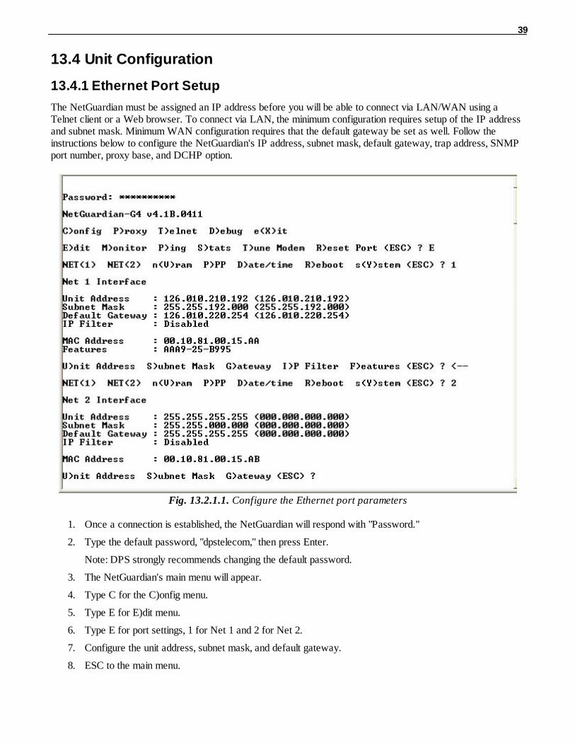
The NetGuardian must be assigned an IP address before you will be able to connect via LAN/WAN using aTelnet client or a Web browser. To connect via LAN, the minimum configuration requires setup of the IP addressand subnet mask. Minimum WAN configuration requires that the default gateway be set as well. Follow theinstructions below to configure the NetGuardian's IP address, subnet mask, default gateway, trap address, SNMPport number, proxy base, and DCHP option.
Fig. 13.2.1.1. Configure the Ethernet port parameters
1. Once a connection is established, the NetGuardian will respond with "Password."
2. Type the default password, "dpstelecom," then press Enter.
Note: DPS strongly recommends changing the default password.
3. The NetGuardian's main menu will appear.
4. Type C for the C)onfig menu.
5. Type E for E)dit menu.
6. Type E for port settings, 1 for Net 1 and 2 for Net 2.
7. Configure the unit address, subnet mask, and default gateway.
8. ESC to the main menu.
40
9. When asked if you would like to save changes, type Y (yes).
10. Reboot to save the new configuration to the NetGuardian.
11. Now you can connect to the NetGuardian via LAN and complete the configuration.
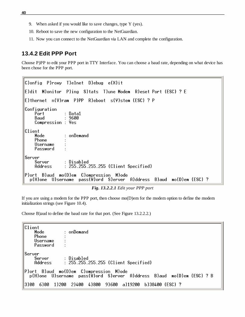
13.4.2 Edit PPP Port
Choose P)PP to edit your PPP port in TTY Interface. You can choose a baud rate, depending on what device hasbeen chose for the PPP port.
Fig. 13.2.2.1 Edit your PPP port
If you are using a modem for the PPP port, then choose mo(D)em for the modem option to define the modeminitialization strings (see Figure 10.4).
Choose B)aud to define the baud rate for that port. (See Figure 13.2.2.2.)

41
Fig. 13.2.2.2. Select the baud rate for your PPP port
Monitoring13.5
13.5.1 Monitoring the NetGuardian
Connect a PC running VT100 terminal emulation software to the craft port or connect via LAN using a Telnetclient with VT100 emulation to port 2002 to reach the monitor menu selection. This section allows you to do fullsystem monitoring of the NetGuardian including: all alarms, ping information, relays, analogs, and system status.
Fig. 13.3.1.1. The monitor menu allows status checking on all elements
13.5.1.1 Monitoring Base Alarms
View the status of the device connected to the discrete alarms from the M)onitor menu > A)larms option. Under Status, the word Alarm will appear if an alarm has been activated and Clear will appear if an alarm condition isnot present. If groups are used the user defined status will be displayed.
Fig. 13.3.1.1.1. This example shows page two of the discrete alarms

42
13.5.1.2 Monitoring Ping Targets
View the status of all your ping targets from the M)onitor menu > P)ing targets option. This screen displays theping target ID, description, and IP address. Under Status the word Alarm will appear if an alarm has beenactivated and Clear will appear if an alarm condition is not present.
Fig. 13.3.1.2.1. The Ping info submenu allows you to change ping targets
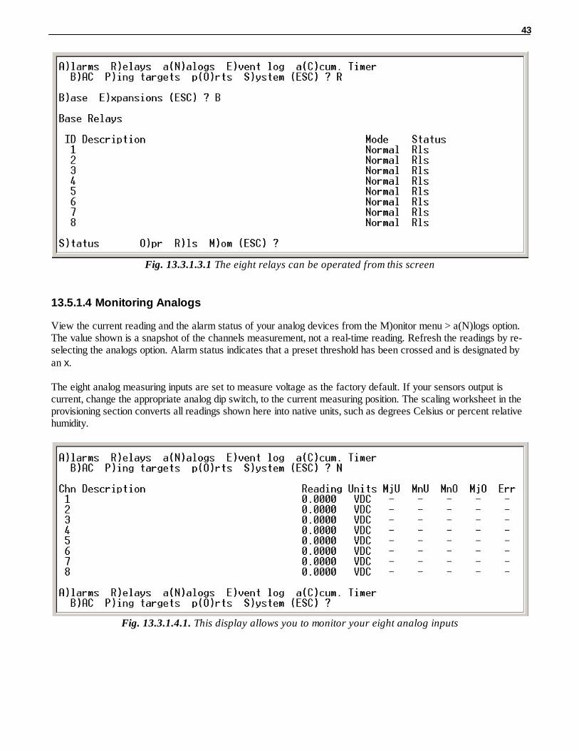
13.5.1.3 Monitoring and Operating Relays (Controls)
The NetGuardian comes equipped with 8 relays that can be used to control external devices. Monitor the status ofyour relays from the M)onitor menu > R)elays option.
Relays are set to normally open (N/O) as the factory default, but each or all of them can be changed to normallyclosed (N/C) by changing their respective jumper (see Section 6.12, "Jumper Options").
43
Fig. 13.3.1.3.1 The eight relays can be operated from this screen
13.5.1.4 Monitoring Analogs
View the current reading and the alarm status of your analog devices from the M)onitor menu > a(N)logs option.The value shown is a snapshot of the channels measurement, not a real-time reading. Refresh the readings by re-selecting the analogs option. Alarm status indicates that a preset threshold has been crossed and is designated byan x.
The eight analog measuring inputs are set to measure voltage as the factory default. If your sensors output iscurrent, change the appropriate analog dip switch, to the current measuring position. The scaling worksheet in theprovisioning section converts all readings shown here into native units, such as degrees Celsius or percent relativehumidity.
Fig. 13.3.1.4.1. This display allows you to monitor your eight analog inputs

44
13.5.1.5 Monitoring System Alarms
View the status of the NetGuardian's system alarms from the M)onitor menu > S)ystem option. Under Status, theword Alarm will appear if an alarm has been activated and Clear will appear if an alarm condition is not present.See Appendix, "System Alarm Descriptions," for more information. If groups are used the user defined status willbe displayed.
Fig. 13.3.1.5.1. System Alarms can be viewed from the M)onitor menu > S)ystem option
13.5.1.6 Monitoring Data Port Activity
View the status of the NetGuardian's 8 data ports from the M)onitor menu > p(O)rts option. Enter the number ofthe port you wish to view and press Enter.
The NetGuardian provides an ASCII description under Transmit and Receive. Choose a) Transmit to view datatransmitted to another device. Choose b) Receive to view data received from another device. See Appendix,"ASCII Conversion," for specific ASCII symbol conversion.
Fig. 13.3.1.6.1. Data port activity can be viewed from the M)onitor menu > p(O)rts option
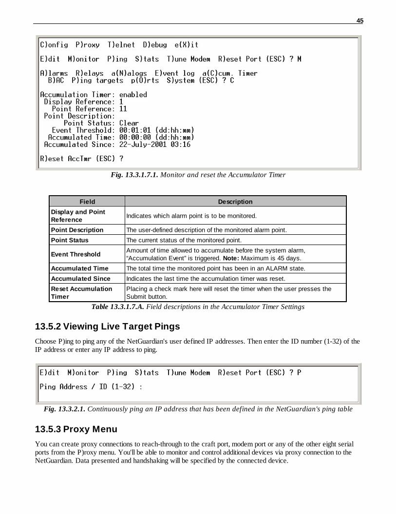
13.5.1.7 Monitoring the Accumulation Timer
The Accumulation Timer keeps a running total of the amount of time a point is in an alarm state. An alarm pointthat exceeds a user defined threshold will trigger a Accumulation Event system alarm. Refer to Figure 13.3.1.7.1.and Table 13.3.1.7.A to define the accumulation timer.
45
Fig. 13.3.1.7.1. Monitor and reset the Accumulator Timer
Field Description
Display and PointReference
Indicates which alarm point is to be monitored.
Point Description The user-defined description of the monitored alarm point.
Point Status The current status of the monitored point.
Event ThresholdAmount of time allowed to accumulate before the system alarm,“Accumulation Event” is triggered. Note: Maximum is 45 days.
Accumulated Time The total time the monitored point has been in an ALARM state.
Accumulated Since Indicates the last time the accumulation timer was reset.
Reset AccumulationTimer
Placing a check mark here will reset the timer when the user presses theSubmit button.
Table 13.3.1.7.A. Field descriptions in the Accumulator Timer Settings
13.5.2 Viewing Live Target Pings
Choose P)ing to ping any of the NetGuardian's user defined IP addresses. Then enter the ID number (1-32) of theIP address or enter any IP address to ping.
Fig. 13.3.2.1. Continuously ping an IP address that has been defined in the NetGuardian's ping table
13.5.3 Proxy Menu
You can create proxy connections to reach-through to the craft port, modem port or any of the other eight serialports from the P)roxy menu. You'll be able to monitor and control additional devices via proxy connection to theNetGuardian. Data presented and handshaking will be specified by the connected device.
46
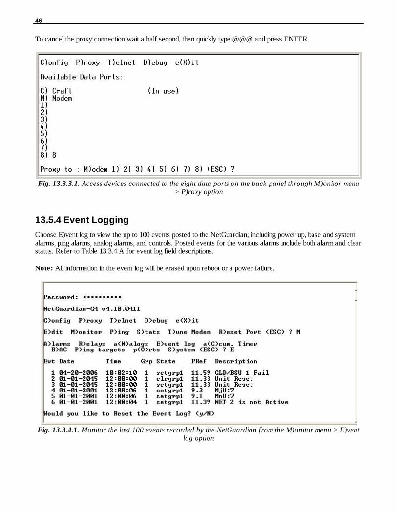
To cancel the proxy connection wait a half second, then quickly type @@@ and press ENTER.
Fig. 13.3.3.1. Access devices connected to the eight data ports on the back panel through M)onitor menu> P)roxy option
13.5.4 Event Logging
Choose E)vent log to view the up to 100 events posted to the NetGuardian; including power up, base and systemalarms, ping alarms, analog alarms, and controls. Posted events for the various alarms include both alarm and clearstatus. Refer to Table 13.3.4.A for event log field descriptions.
Note: All information in the event log will be erased upon reboot or a power failure.
Fig. 13.3.4.1. Monitor the last 100 events recorded by the NetGuardian from the M)onitor menu > E)ventlog option

47
Event Log Field Description
Evt Event number (1–100)
Date Date the event occurred
Time Time the event occurred
Grp Alarm Group
State State of the event (A=alarm, C=clear)
PRef Point reference (See Appendix A for display descriptions).
DescriptionUser defined description of the event as entered in the alarm point andrelay description fields.
Table 13.3.4.A. Event Log field descriptions
13.5.5 Backing Up NetGuardian Configuration Data via FTP
1. From the Start menu on your PC, select RUN.
2. Type "ftp" followed by the IP address of the NetGuardian you are backing up (e.g. ftp 126.10.120.199).
3. After the connection is made press Enter.
4. Enter the password of the NetGuardian (default password is dpstelecom), then press Enter.
5. Type "binary" and press Enter (necessary for NetGuardian file transfer).
6. Type "lcd" and press Enter (this allows you to change the directory of your local machine).
7. Type "get" followed by the name you wish to define for the NetGuardian backup file. Add the extension".ngd" to the file name (e.g. get ngdbkup.ngd) and press Enter.
8. After reloading, type "bye" and press Enter to exit.
Note: The backup file name can have a maximum of eight characters before the file extension.
13.5.5.1 Reloading NetGuardian Configuration Data
1. From the Start menu on your PC, select RUN.
2. Type "ftp" followed by the IP address of the NetGuardian you are backing up (e.g. ftp 126.10.120.199).
3. After the connection is made press Enter.
4. Enter the password of the NetGuardian (default password is dpstelecom), then press ENTER.
5. Type "binary" and press Enter (necessary for NetGuardian file transfer).
6. Type "lcd" and press Enter (this allows you to change the directory of your local machine).
7. Type "put" followed by the name you defined for the NetGuardian backup file and press Enter (e.g. putngdbkup.ngd).
8. Type "literal REBT" to reboot the NetGuardian.

48
9. After reloading, type "bye" and press Enter to exit.
13.5.6 Debug Input and Filter Options
Debug Input Options
ESC Exit Debug
B Show BAC status points
T Show task status
U Show DUART information
R Show network routing table
X Clear debug enable bitmap. Turn all debug filters OFF
? Display Options
Debug Filter Options:
a (1) Alarm toggle switch. Shows posting of alarm data
A (2) Analog toggle switch. Shows TTY interface debug
c (3) Config toggle switch. Shows TTY interface debug
C (4) Control relay toggle switch. Shows relay operation
d (5) DCP responder toggle switch. Shows DCP protocol
D(6) Device toggle switch. Shows telnet and proxy information and NGEdit4 serialcommunication.
e (7) Expansion poller toggle switch. Shows NGDdx polling
E (8) ECU Interrogator toggle switch. Shows BAC processing
f (9) FTP Command toggle switch. Shows command string parsing
F (10) FTP Data toggle switch. Shows FTP Read / Write
G (11) GLD poller toggle switch. Shows GLD polling
h (12) HTML debug switch. Shows Web Browser processing
H (13) HWACS debug switch. Shows hardware access operation
i (14) PING toggle switch
k (15) Socket toggle switch. Shows current dcu resources
l (16) LED toggle switch. Shows current LED state
L (17) LCD display toggle switch. Shows LCD control and text
m (18) Modem toggle switch. Shows modem vectored initialization
M (19) Undefined
o(20) Osstart toggle switch. Miscellaneous application debug, including NVRAMread and write operation, and event posting
O (21) Undefined
p (22) SPORT toggle switch. Port init debug and channeled port debug
P (23) PPP toggle switch. Shows PPP functioning
q (24) QAccess toggle switch. Reserved for future use
Q (25) Undefined
r(26) Report toggle switch. Shows reporting event activity, including SNMP,pagers, email, etc. Also shows PPP negotiation for NG client PPP mode.
s (27) SNMP toggle switch. Reserved for future use
S(28) STAK toggle switch. Shows network processing and IPA of arp requests. Also shows packets discarded by Filter IPA.
t (29) TERM toggle switch. Shows UDP/TCP port handling. The camera and

49
network time (NTP) jobs also use the TERM toggle switch
V (30) Undefined
w (31) HTTP toggle switch. Shows handling of web browser packets
W (32) WEB toggle switch 2. Dump HTML text from web browser
Table. 13.3.A. Debut Input and Filter Options
Reference Section14
Display Mapping14.1
Port Address Display Description Set Clear
99 1 1 Discrete Alarms 1-32 8001-8032 9001-9032
99 1 2 Ping Table 8065-8096 9065-9096
99 1 3 Analog Channel 1** 8129-8132 9129-9132
99 1 4 Analog Channel 2** 8193-8196 9193-9196
99 1 5 Analog Channel 3** 8257-8260 9257-9260
99 1 6 Analog Channel 4** 8321-8324 9321-9324
99 1 7 Analog Channel 5** 8385-8388 9385-9388
99 1 8 Analog Channel 6** 8449-8452 9449-9452
99 1 9 Analog Channel 7** 8513-8516 9513-9516
99 1 10 Analog Channel 8** 8577-8580 9577-9580
99 1 11 Relays/System Alarms (See table below) 8641-8674 9641-9674
99 1 12 NetGuardian Expansion 1 Alarms 1-48 6001-6064 7001-7064
99 1 12 NetGuardian 480 (as DX) Alarms 1-64 6001-6064 7001-7064
99 1 13 NetGuardian Expansion 1 Relays 1-8 orNetGuardian 480 (as DX) Relays 1-4
6065-6072 7065-7072
99 1 13 NetGuardian 480 (as DX) Alarms 65-80 6081-6096 7081-7096
99 1 14 NetGuardian Expansion 2 Alarms 1-48 6129-6177 7129-7177
99 1 15 NetGuardian Expansion 2 Relays 1-8 6193-6200 7193-7200
99 1 16 NetGuardian Expansion 3 Alarms 1-48 6257-6305 7257-7305
99 1 17 NetGuardian Expansion 3 Relays 1-8 6321-6328 7321-7328
99 1 26 DSCP ALG 1/2(Propane Sensor, Battery Voltage) 6449-6452 7449-7452
99 1 27 DSCP ALG 3/4 6513-6516 7513-7516
99 1 28 DSCP ALG 5/6 6577-6580 7577-7580
Table 14.1.A. Display descriptions and SNMP Trap numbers for the NetGuardian
* The TRAP number ranges shown correspond to the point range of each display. For example, the SNMP Trap"Set" number for alarm 1 (in Display 1) is 8001, "Set" for alarm 2 is 8002, "Set" for alarm 3 is 8003, etc.
** The TRAP number descriptions for the Analog channels (1-8) are in the following order: minor under, minorover, major under, and major over. For example, for Analog channel 1, the "Set" number for minor under is 8129,minor over is 8130, major under is 8131, and major over is 8132.

50
SNMP Trap #s
Points Description Set Clear
1 Relays 8641 9641
2 Relays 8642 9642
3 Relays 8643 9643
4 Relays 8644 9644
5 Relays 8645 9645
6 Relays 8646 9646
7 Relays 8647 9647
8 Relays 8648 9648
17 Timed Tick 8657 9657
18 Exp. Module Callout 8658 9658
19 Network Time Server 8659 9659
21 Duplicate IP Address 8661 9661
33 Power Up 8673 9673
36 Lost Provisioning 8676 9676
37 DCP Poller Inactive 8677 9677
38 LAN not active 8678 9678
41 Modem not responding 8681 9681
42 No Dial Tone 8682 9682
43 SNMP Trap not Sent 8683 9683
44 Pager Que Overflow 8684 9684
45 Notification failed 8685 9685
46 Craft RcvQ full 8686 9686
47 Modem RcvQ full 8687 9687
48 Serial 1 RcvQ full 8688 9688
49 Serial 2 RcvQ full 8689 9689
50 Serial 3 RcvQ full 8690 9690
51 Serial 4 RcvQ full 8691 9691
52 Serial 5 RcvQ full 8692 9692
53 Serial 6 RcvQ full 8693 9693
54 Serial 7 RcvQ full 8694 9694
55 Serial 8 RcvQ full 8695 9695
56 NetGuardian DX 1 fail 8696 9696
57 NetGuardian DX 2 fail 8697 9697
58 NetGuardian DX 3 fail 8698 9698
59 GLD 1 fail 8699 9699
60 GLD 2 fail 8700 9700
61 GLD 3+ fail 8701 9701
62 Chan. Port Timeout 8702 9702
63 Craft Timeout 8703 9703
64 Event Que Full 8704 9704
51
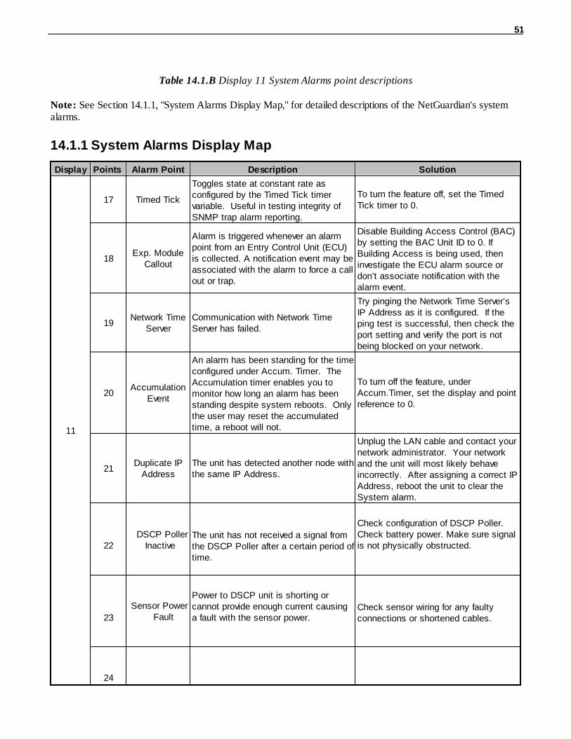
Table 14.1.B Display 11 System Alarms point descriptions
Note: See Section 14.1.1, "System Alarms Display Map," for detailed descriptions of the NetGuardian's systemalarms.
14.1.1 System Alarms Display Map
Display Points Alarm Point Description Solution
11
17 Timed Tick
Toggles state at constant rate asconfigured by the Timed Tick timervariable. Useful in testing integrity ofSNMP trap alarm reporting.
To turn the feature off, set the TimedTick timer to 0.
18Exp. Module
Callout
Alarm is triggered whenever an alarmpoint from an Entry Control Unit (ECU)is collected. A notification event may beassociated with the alarm to force a callout or trap.
Disable Building Access Control (BAC)by setting the BAC Unit ID to 0. IfBuilding Access is being used, theninvestigate the ECU alarm source ordon’t associate notification with thealarm event.
19Network Time
ServerCommunication with Network TimeServer has failed.
Try pinging the Network Time Server’sIP Address as it is configured. If theping test is successful, then check theport setting and verify the port is notbeing blocked on your network.
20Accumulation
Event
An alarm has been standing for the timeconfigured under Accum. Timer. TheAccumulation timer enables you tomonitor how long an alarm has beenstanding despite system reboots. Onlythe user may reset the accumulatedtime, a reboot will not.
To turn off the feature, underAccum.Timer, set the display and pointreference to 0.
21Duplicate IP
AddressThe unit has detected another node withthe same IP Address.
Unplug the LAN cable and contact yournetwork administrator. Your networkand the unit will most likely behaveincorrectly. After assigning a correct IPAddress, reboot the unit to clear theSystem alarm.
22
DSCP Poller Inactive
The unit has not received a signal fromthe DSCP Poller after a certain period oftime.
Check configuration of DSCP Poller.Check battery power. Make sure signalis not physically obstructed.
23
Sensor Power Fault
Power to DSCP unit is shorting orcannot provide enough current causinga fault with the sensor power.
Check sensor wiring for any faultyconnections or shortened cables.
24

52
Sensor Power Low
DSCP unit is not providing enoughpower to the sensors.
Check sensor wiring for any faultyconnections or shortened cables.
33 Power UpThe unit has just come-online. The setalarm condition is followed immediatelyby a clear alarm condition.
Seeing this alarm is normal if the unit ispowering up.
36Lost
Provisioning
The internal NVRAM may be damaged. The unit is using default configurationsettings.
Use Web or latest version of NGEdit4to configure unit. Power cycle to see ifalarm goes away. May require RMA.
Table 14.1.1.A. System Alarms Descriptions
Note: Table 14.1.1.A. continues on following pages.

53
Display Points Alarm Point Description Solution
11
37DCP Poller
Inactive
The unit has not seen a poll from theMaster for the time specified by theDCP Timer setting.
If DCP responder is not being used,then set the DCP Unit ID to 0. Otherwise, try increasing the DCPtimer setting under timers, or checkhow long it takes to cycle through thecurrent polling chain on the Mastersystem.
38 NET1 not active The Net1 LAN port is down. Check LAN cable. Ping to and fromthe unit.39 NET2 not active The Net2 LAN port is down.
40 LNK Alarm No network connection detected
41Modem notresponding
An error has been detected duringmodem initialization. The modem didnot respond to the initialization string.
Remove configured modem initializationstring, then power cycle the unit. Ifalarm persists, try resetting the Modemport from the TTY interface, or contactDPS for possible RMA.
42 No Dial ToneDuring dial-out attempt, the unit did notdetect a dial tone.
Check the integrity of the phone lineand cable.
43SNMP Trap not
SentSNMP trap address is not defined andan SNMP trap event occurred.
Define the IP Address where you wouldlike to send SNMP trap events, orconfigure the event not to trap.
44Pager Queue
Overflow
Over 250 events are currently queued inthe pager queued and are still trying toreport.
Check for failed notification events thatmay be filling up the pager queue.There may be a configuration orcommunication problem with thenotification events.
45Notification
failedA notification event, like a page oremail, was unsuccessful.
Use RPT filter debug to help diagnosenotification problems.
46 Craft RcvQ fullThe Craft port received more data thanit was able to process.
Disconnect whatever device isconnected to the craft serial port. Thisalarm should not occur.
47Modem RcvQ
fullThe modem port received more datathan it was able to process.
Check what is connecting to theNetGuardian. This alarm should notoccur.
48Serial 1 RcvQ
full
Serial port 1 (or appropriate serial portnumber) receiver filled with 8 K of data(4 K if BAC active).
Check proxy connection. The serialport data may not be getting collectedas expected.
49Serial 2 RcvQ
full
50Serial 3 RcvQ
full
51Serial 4 RcvQ
full
52Serial 5 RcvQ
full
53Serial 6 RcvQ
full
54Serial 7 RcvQ
full
55Serial 8 RcvQ
full

54
Table 14.1.1.A System Alarms Descriptions (continued)Note: Table 14.1.1.A continues on following page.
Display Points Alarm Point Description Solution
11
56NetGuardian
DX 1 failNGDdx 1 Fail (Expansion shelf 1communication link failure)
Under Ports > Options, verify thenumber of configured NGDdx units. Use EXP filter debug and port LEDs tohelp diagnose the problem. Use DB9Mto DB9M with null crossover for cabling. Verify the DIP addressing on the backof the NGDdx unit.
57NetGuardian
DX 2 failNGDdx 2 Fail (Expansion shelf 2communication link failure)
58NetGuardian
DX 3 failNGDdx 3 Fail (Expansion shelf 3communication link failure)
59 GLD 1 fail GLD address 1 is failed.
Connect just GLD unit 1 and attempt topoll. Verify GLD is connected to dataport 8 and the hardware is RS485, notRS232.
60 GLD 2 fail GLD address 2 is failed.Verify the GLD unit addressing, andtest GLD units individually on the GLDcommunication bus.
61 GLD 3+ failOne or more GLD units addressed 3through 12 may be failed.
Reduce the number of connected GLDunits to determine which unit may becausing the link to fail.
62Chan. Port
Timeout
Chan. Port has not forwarded any trafficin the time specified by the ChannelTimeout Timer. The channel featureforwards data between two ports so theNG may be used to analyze serialtraffic using CHAN filter debug.
Change the data port type to OFF, orset the Channel Timer to a differentsetting.
63 Craft Timeout
The Craft Timeout Timer has not beenreset in the specified time. This featureis designed so other machines maykeep the TTY link active. If the TTYinterface becomes unavailable to themachine, then the Craft Timeout alarmis set.
Change the Craft Timeout Timer to 0 todisable the feature.
64 Event Que FullThe Event Que is filled with more than500 uncollected events.
Enable DCP timestamp polling on themaster so events are collected, orreboot the system to clear the alarm.
Table 14.1.1.A System Alarms Descriptions (continued)
55
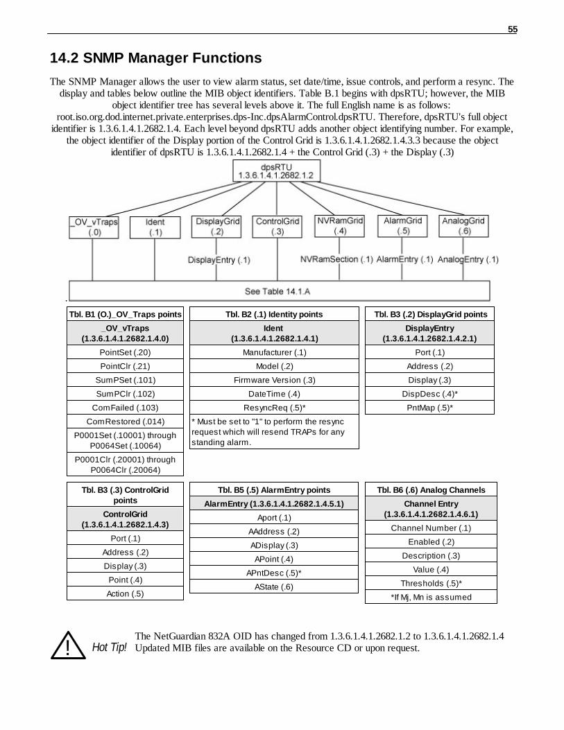
SNMP Manager Functions14.2
The SNMP Manager allows the user to view alarm status, set date/time, issue controls, and perform a resync. Thedisplay and tables below outline the MIB object identifiers. Table B.1 begins with dpsRTU; however, the MIB
object identifier tree has several levels above it. The full English name is as follows: root.iso.org.dod.internet.private.enterprises.dps-Inc.dpsAlarmControl.dpsRTU. Therefore, dpsRTU's full object
identifier is 1.3.6.1.4.1.2682.1.4. Each level beyond dpsRTU adds another object identifying number. For example,the object identifier of the Display portion of the Control Grid is 1.3.6.1.4.1.2682.1.4.3.3 because the object
identifier of dpsRTU is 1.3.6.1.4.1.2682.1.4 + the Control Grid (.3) + the Display (.3)
.
Tbl. B1 (O.)_OV_Traps points
_OV_vTraps(1.3.6.1.4.1.2682.1.4.0)
PointSet (.20)
PointClr (.21)
SumPSet (.101)
SumPClr (.102)
ComFailed (.103)
ComRestored (.014)
P0001Set (.10001) throughP0064Set (.10064)
P0001Clr (.20001) throughP0064Clr (.20064)
Tbl. B2 (.1) Identity points
Ident (1.3.6.1.4.1.2682.1.4.1)
Manufacturer (.1)
Model (.2)
Firmware Version (.3)
DateTime (.4)
ResyncReq (.5)*
* Must be set to "1" to perform the resyncrequest which will resend TRAPs for anystanding alarm.
Tbl. B3 (.2) DisplayGrid points
DisplayEntry(1.3.6.1.4.1.2682.1.4.2.1)
Port (.1)
Address (.2)
Display (.3)
DispDesc (.4)*
PntMap (.5)*
Tbl. B3 (.3) ControlGridpoints
ControlGrid(1.3.6.1.4.1.2682.1.4.3)
Port (.1)
Address (.2)
Display (.3)
Point (.4)
Action (.5)
Tbl. B5 (.5) AlarmEntry points
AlarmEntry (1.3.6.1.4.1.2682.1.4.5.1)
Aport (.1)
AAddress (.2)
ADisplay (.3)
APoint (.4)
APntDesc (.5)*
AState (.6)
Tbl. B6 (.6) Analog Channels
Channel Entry(1.3.6.1.4.1.2682.1.4.6.1)
Channel Number (.1)
Enabled (.2)
Description (.3)
Value (.4)
Thresholds (.5)*
*If Mj, Mn is assumed
! Hot Tip!The NetGuardian 832A OID has changed from 1.3.6.1.4.1.2682.1.2 to 1.3.6.1.4.1.2682.1.4Updated MIB files are available on the Resource CD or upon request.
56
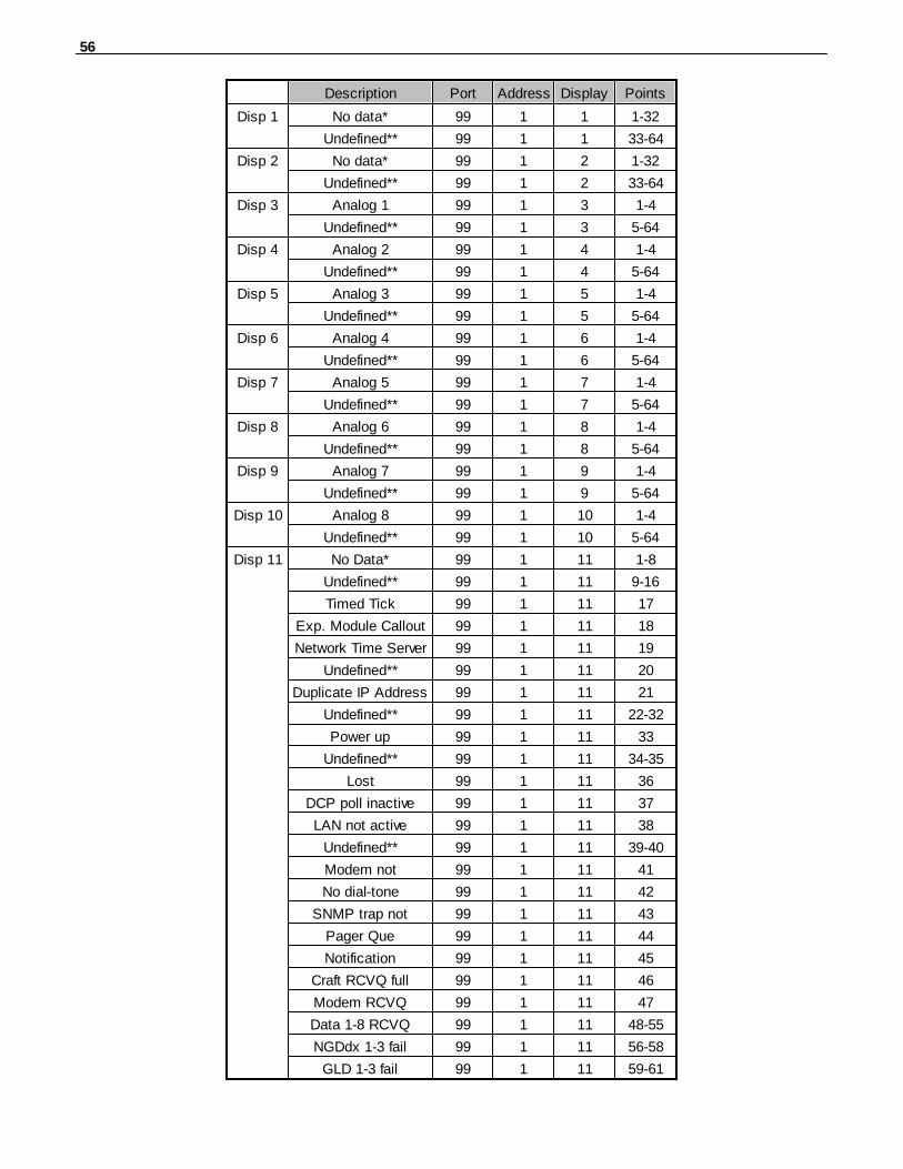
Description Port Address Display Points
Disp 1 No data* 99 1 1 1-32
Undefined** 99 1 1 33-64
Disp 2 No data* 99 1 2 1-32
Undefined** 99 1 2 33-64
Disp 3 Analog 1 99 1 3 1-4
Undefined** 99 1 3 5-64
Disp 4 Analog 2 99 1 4 1-4
Undefined** 99 1 4 5-64
Disp 5 Analog 3 99 1 5 1-4
Undefined** 99 1 5 5-64
Disp 6 Analog 4 99 1 6 1-4
Undefined** 99 1 6 5-64
Disp 7 Analog 5 99 1 7 1-4
Undefined** 99 1 7 5-64
Disp 8 Analog 6 99 1 8 1-4
Undefined** 99 1 8 5-64
Disp 9 Analog 7 99 1 9 1-4
Undefined** 99 1 9 5-64
Disp 10 Analog 8 99 1 10 1-4
Undefined** 99 1 10 5-64
Disp 11 No Data* 99 1 11 1-8
Undefined** 99 1 11 9-16
Timed Tick 99 1 11 17
Exp. Module Callout 99 1 11 18
Network Time Server 99 1 11 19
Undefined** 99 1 11 20
Duplicate IP Address 99 1 11 21
Undefined** 99 1 11 22-32
Power up 99 1 11 33
Undefined** 99 1 11 34-35
Lost 99 1 11 36
DCP poll inactive 99 1 11 37
LAN not active 99 1 11 38
Undefined** 99 1 11 39-40
Modem not 99 1 11 41
No dial-tone 99 1 11 42
SNMP trap not 99 1 11 43
Pager Que 99 1 11 44
Notification 99 1 11 45
Craft RCVQ full 99 1 11 46
Modem RCVQ 99 1 11 47
Data 1-8 RCVQ 99 1 11 48-55
NGDdx 1-3 fail 99 1 11 56-58
GLD 1-3 fail 99 1 11 59-61

57
CHAN timeout 99 1 11 62
CRFT timeout 99 1 11 63
Table 14.2.A. Alarm Point Descriptions
* "No data" indicates that the alarm point is defined but there is no description entered.** "Undefined" indicates that the alarm point is not used.
SNMP Granular Trap Packets14.3
Tables 14.3.A and 14.3.B provide a list of the information contained in the SNMP Trap packets sent by theNetGuardian.
SNMP Trap managers can use one of two methods to get alarm information: 1. Granular traps (not necessary to define point descriptions for the NetGuardian)
or
2. The SNMP manager reads the description from the Trap.
UDP Header Description
1238 Source port
162 Destination port
303 Length
0xBAB0 Checksum
Table 14.3.A UDP Headers and descriptions

58
SNMP Header Description
0 Version
Public Request
Trap Request
1.3.6.1.4.1.2682.1.4 Enterprise
126.10.230.181 Agent address
Enterprise Specific Generic Trap
8001 Specific Trap
617077 Time stamp
1.3.7.1.2.1.1.1.0 Object
NetGuardian 216 v1.0K Value
1.3.6.1.2.1.1.6.0 Object
1-800-622-3314 Value
1.3.6.1.4.1.2682.1.4.4.1.0 Object
01-02-1995 05:08:27.760 Value
1.3.6.1.4.1.2682.1.4.5.1.1.99.1.1.1 Object
99 Value
1.3.6.1.4.1.2682.1.4.5.1.2.99.1.1.1 Object
1 Value
1.3.6.1.4.1.2682.1.4.5.1.3.99.1.1.1 Object
1 Value
1.3.6.1.4.1.2682.1.4.5.1.4.99.1.1.1 Object
1 Value
1.3.6.1.4.1.2682.1.4.5.1.5.99.1.1.1 Object
Rectifier Failure Value
1.3.6.1.4.1.2682.1.4.5.1.6.99.1.1.1 Object
Alarm Value
Table 14.3.B. SNMP Headers and descriptions

59
Trap SNMP Logic14.4
Table 14.3.C. Trap SNMP Logic
ASCII Conversion14.5
The information contained in Table D.1 is a list of ASCII symbols and their meanings. Refer to the bulleted listbelow to interpret the ASCII data transmitted or received through the data ports. Port transmit and receive activitycan be viewed from the Web Browser Interface.
• Printable ASCII characters will appear as ASCII.• Non-printable ASCII characters will appear as labels surrounded by { } brackets (e.g. {NUL}).• Non-ASCII characters will appear as hexadecimal surrounded by [ ] brackets (e.g. [IF]).• A received BREAK will appear as <BRK>.
Abbreviation Description Abbreviation Description
NUL Null DLE Data Link Escape
SOH Start of Heading DC Device Control
STX Start of Text NAK Negative Acknowledge
ETX End of Text SYN Synchronous Idle
EOT End of Transmission ETB End of Transmission Block
ENQ Enquiry CAN Cancel
ACK Acknowledge EM End of Medium
BEL Bell SUB Substitute
BS Backspace ESC Escape
HT Horizontal Tabulation FS File Separator
LF Line Feed GS Group Separator
VT Vertical Tabulation RS Record Separator
FF Form Feed US Unit Separator
CR Carriage Return SP Space (blank)
SO Shift Out DEL Delete
SI Shift In BRK Break Received
Table 14.4.A. ASCII symbols

60
Frequently Asked Questions15
Here are answers to some common questions from NetGuardian users. The latest FAQs can be found on theNetGuardian support web page, http://www.dpstelecom.com.
If you have a question about the NetGuardian, please call us at (559) 454-1600 or e-mail us [email protected]
General FAQs15.1
Q. How do I telnet to the NetGuardian?A. You must use Port 2002 to connect to the NetGuardian. Configure your Telnet client to connect using TCP/
IP (not "Telnet," or any other port options). For connection information, enter the IP address of theNetGuardian and Port 2002. For example, to connect to the NetGuardian using the standard Windows Telnetclient, click Start, click Run, and type "telnet <NetGuardian IP address> 2002."
Q. How do I connect my NetGuardian to the LAN?A. To connect your NetGuardian to your LAN, you need to configure the unit IP address, the subnet mask and
the default gateway. A sample configuration could look like this:Unit Address: 192.168.1.100subnet mask: 255.255.255.0Default Gateway: 192.168.1.1Save your changes by writing to NVRAM and reboot. Any change to the NetGuardian's IP configurationrequires a reboot.
Q. When I connect to the NetGuardian through the craft port on the front panel it either doesn't workright or it doesn't work at all. What's going on?
A. Make sure your using the right COM port settings. Your COM port settings should read:Bits per second: 9600 (9600 baud)Data bits: 8Parity: NoneStop bits: 1Flow control: NoneImportant! Flow control must be set to none . Flow control normally defaults to hardware in most terminalprograms, and this will not work correctly with the NetGuardian.
Q. I can't change the craft port baud rate.A. If you select a higher baud rate, you must set your terminal emulator program to the new baud rate and then
type DPSCFG and press Enter. If your terminal emulator is set to a slower baud rate than the craft port,normal keys can appear as a break key — and the craft port interprets a break key as an override that resetsthe baud rate to the standard 9600 baud.
Q. How do I use the NetGuardian to access TTY interfaces on remote site equipment?A. If your remote site device supports RS-232, you can connect it to one of the eight data ports located on the
NetGuardian back panel. To make the data port accessible via LAN, configure the port for TCP/IP operation.You now have a LAN-based proxy port connection that lets you access your device's TTY interface througha Telnet session.
Q. How do I telnet to the NetGuardian?A. Configure your Telnet client with these options:
· Connect using TCP/IP (not "Telnet," or any other port options)

61
· Enter the IP address of the NetGuardian
· Enter Port 2002Example:To connect using the Windows Telnet client, click Start, click Run, and type telnet 126.12.220.8 2002.
Q. I just changed the port settings for one of my data ports, but the changes did not seem to takeeffect even after I wrote the NVRAM.
A. In order for data port and craft port changes (including changes to the baud rate and word format) to takeeffect, the NetGuardian must be rebooted. Whenever you make changes, remember to write them to theNetGuardian's NVRAM so they will be saved when the unit is rebooted.
Q. The LAN link LED is green on my NetGuardian, but I can't poll it from my T/Mon.A. Some routers will not forward packets to an IP address until the MAC address of the destination device has
been registered on the router's Address Resolution Protocol (ARP) table. Enter the IP address of yourgateway and your T/Mon system to the ARP table.
Q. What do the terms "port," "address," "display" and "alarm point" mean?A. These terms refer to numbers that designate the location of a network alarm, from the most general (a port to
which several devices are connected) to the most specific (an individual alarm sensor).Port: A number designating a serial port through which a monitoring device collects data.Address: A number designating a device connected to a port.Display: A number designating a logical group of 64 alarm points.Alarm Point: A number designating a contact closure that is activated when an alarm condition occurs. Forexample, an alarm point might represent a low oil sensor in a generator or an open/close sensor in a door.These terms originally referred only to physical things: actual ports, devices, and contact closures. For the sakeof consistency, port-address-display-alarm point terminology has been extended to include purely logicalelements: for example, the NetGuardian reports internal alarms on Port 99, Address 1.
Q. What characteristics of an alarm point can be configured through software? For instance, can point4 be used to sense an active-low signal, or point 5 to sense a level or a edge?
A. The NetGuardian's standard configuration is for all alarm points to be level-sensed. You cannot useconfiguration software to convert alarm points to TTL (edge-sensed) operation. TTL alarm points are ahardware option that must be specified when you order your NetGuardian. Ordering TTL points for yourNetGuardian does not add to the cost of the unit What you can do with the configuration software is changeany alarm point from "Normal" to "Reversed" operation. Switching to Reversed operation has different effects,depending on the kind of input connected to the alarm point:
· If the alarm input generates an active-high signal, switching to Reversed operation means theNetGuardian will declare an alarm in the absence of the active-high signal, creating the practical equivalent ofan active-low alarm.
· If the alarm input generates an active-low signal, switching to Reversed operation means theNetGuardian will declare an alarm in the absence of the active-low signal, creating the practical equivalent ofan active-high alarm.
· If the alarm input is normally open, switching to Reversed operation converts it to a normally closedalarm point.
· If the alarm input is normally closed, switching to Reversed operation converts it to a normally openalarm point.
Q. Every time my NetGuardian starts up, I have to reenter the date and time. How can I get theNetGuardian to automatically maintain the date and time setting?
A. You have three options for keeping the correct time on your NetGuardian:Real Time Clock Option: You can order your NetGuardian with the Real Time Clock hardware option.Once it's set, the Real Time Clock will keep the correct date and time, regardless of reboots.
62
Network Time Protocol Synchronization: If your NetGuardian has Firmware Version 2.9F or later, youcan configure the unit to automatically synchronize to a Network Time Protocol (NTP) server.
· To get the latest NetGuardian firmware, sign in to MyDPS at www.dpstelecom.com/mydps.
· For instructions on configuring your NetGuardian to use NTP synchronization, see your NGEdit4 orNetGuardian Web Browser Interface user manual.T/Mon RTU Time Sync Signal: You can configure your T/Mon NOC to send an RTU Time Sync signal ata regular interval, which you can set to any time period between 10 and 10,080 minutes. The Time Sync willautomatically synchronize the NetGuardian's clock to the T/Mon's clock. And if you set your T/Mon to NTPsynchronization, you'll make sure you have consistent, accurate time stamps throughout your monitoringnetwork.
Q. How do I back up my NetGuardian configuration?A. There are two ways to back up NetGuardian configuration files:
Use NGEdit4NGEdit4 can read the configuration of a NetGuardian unit connected to your PC via LAN, modem or COMport. You can then use NGEdit4 to save a NetGuardian configuration file on your PC's hard disk or on afloppy disk. With NGEdit4 you can also make changes to the configuration file and write the changedconfiguration to the NetGuardian's NVRAM.Use FTPYou can use File Transfer Protocol (FTP) to read and write configuration files to the NetGuardian's NVRAM,but you can't use FTP to edit configuration files.
SNMP FAQs15.2
Q. Which version of SNMP is supported by the SNMP agent on the NetGuardian?A. SNMP v1 and v2.0c.
Q. How do I configure the NetGuardian to send traps to an SNMP manager? Is there a separate MIBfor the NetGuardian? How many SNMP managers can the agent send traps to? And how do I setthe IP address of the SNMP manager and the community string to be used when sending traps?
A. The NetGuardian begins sending traps as soon as the SNMP managers are defined. The NetGuardian MIB isincluded on the NetGuardian Resource CD. The MIB should be compiled on your SNMP manager. (Note:MIB versions may change in the future.) The unit supports a main SNMP manager, which is configured byentering its IP address in the Trap Address field of Ethernet Port Setup. You can also configure up to eightsecondary SNMP managers, which is configured by selecting the secondary SNMP managers as pagerrecipients. Community strings are configured globally for all SNMP managers. To configure the communitystrings, choose System from the Edit menu, and enter appropriate values in the Get, Set, and Trap fields.
Q. Does the NetGuardian support MIB-2 and/or any other standard MIBs?A. The NetGuardian supports the bulk of MIB-2.
Q. Does the NetGuardian SNMP agent support both NetGuardian and T/MonXM variables?A. The NetGuardian SNMP agent manages an embedded MIB that supports only the NetGuardian's RTU
variables. The T/MonXM variables are included in the distributed MIB only to provide SNMP managers witha single MIB for all DPS Telecom products.
Q. How many traps are triggered when a single point is set or cleared? The MIB defines traps like"major alarm set/cleared," "RTU point set," and a lot of granular traps, which could imply thatmore than one trap is sent when a change of state occurs on one point.
A. Generally, a single change of state generates a single trap, but there are two exception to this rule. Exception1: the first alarm in an "all clear" condition generates an additional "summary point set" trap. Exception 2: thefinal clear alarm that triggers an "all clear" condition generates an additional "summary point clear" trap.

63
Q. What does "point map" mean?A. A point map is a single MIB leaf that presents the current status of a 64-alarm-point display in an ASCII-
readable form, where a "." represents a clear and an "x" represents an alarm.
Q. The NetGuardian manual talks about eight control relay outputs. How do I control these from mySNMP manager?
A. The control relays are operated by issuing the appropriate set commands, which are contained in the DPSTelecom MIB. For more information about the set commands, see Appendix, "Display Mapping," in any of theNetGuardian software configuration guides.
Q. How can I associate descriptive information with a point for the RTU granular traps?A. The NetGuardian alarm point descriptions are individually defined using the Web Browser, TTY, or NGEdit4
configuration interfaces.
Q. My SNMP traps aren't getting through. What should I try?A. Try these three steps:
1. Make sure that the Trap Address (IP address of the SNMP manager) is defined. (If you changed theTrap Address, make sure you saved the change to NVRAM and rebooted.)
2. Make sure all alarm points are configured to send SNMP traps.3. Make sure the NetGuardian and the SNMP manager are both on the network. Use the NetGuardian's
ping command to ping the SNMP manager.
Pager FAQs15.3
Q. Why won't my alpha pager work?A. To configure the NetGuardian to send alarm notifications to an alpha pager, enter the data phone number for
your pager in the Phone Number field. This phone number should connect to your pager service's modem.Then enter the PIN for your pager in the PIN/Rcpt/Port field. You don't need to enter anything in any of theother fields. If you still don't receive pages, try setting the Dial Modem Init string to ATS37=9. This will limitthe NetGuardian's connection speed.
Q. Numeric pages don't come in or are cut off in the middle of the message. What's wrong?A. You need to set a delay between the time the NetGuardian dials your pager number and the time the
NetGuardian begins sending the page message. You can set the delay in the Pager Number field, where youenter your pager number. First enter the pager number, then enter some commas directly after the number.Each comma represents a two-second delay. So, for example, if you wanted an eight-second delay, you wouldenter "555-1212,,,," in the Pager Number field.
Q. What do I need to do to set up e-mail notifications?A. You need to assign the NetGuardian an e-mail address and list the addresses of e-mail recipients. Let's explain
some terminology. An e-mail address consists of two parts, the user name (everything before the "@" sign)and the domain (everything after the "@" sign). To assign the NetGuardian an e-mail address, choose Systemfrom the Edit menu. Enter the NetGuardian's user name in the Name field (it can't include any spaces) and thedomain in the Location field. For example, if the system configuration reads:
Name: netguardianLocation: proactive.com
Then e-mail notifications from the NetGuardian will be sent from the address "[email protected]."The next step is to list the e-mail recipients. Choose Pagers from the Edit menu. For each e-mail recipient,enter his or her e-mail domain in the Phone/Domain field and his or her user name in the PIN/Rcpt/Port field.You must also enter the IP address of an SNMP server in the IPA field.

64
Technical Support16
DPS Telecom products are backed by our courteous, friendly Technical Support representatives, who will give youthe best in fast and accurate customer service. To help us help you better, please take the following steps beforecalling Technical Support:
1. Check the DPS Telecom website.You will find answers to many common questions on the DPS Telecom website, at http://www.dpstelecom.com/support/. Look here first for a fast solution to your problem.
2. Prepare relevant information.
Having important information about your DPS Telecom product in hand when you call will greatly reduce thetime it takes to answer your questions. If you do not have all of the information when you call, our TechnicalSupport representatives can assist you in gathering it. Please write the information down for easy access. Pleasehave your user manual and hardware serial number ready.
3. Have access to troubled equipment.Please be at or near your equipment when you call DPS Telecom Technical Support. This will help us solve yourproblem more efficiently.
4. Call during Customer Support hours.Customer support hours are Monday through Friday, from 7 A.M. to 6 P.M., Pacific time. The DPS TelecomTechnical Support phone number is (559) 454-1600.
Emergency Assistance: Emergency assistance is available 24 hours a day, 7 days a week. For emergencyassistance after hours, allow the phone to ring until it is answered with a paging message. You will beasked to enter your phone number. An on-call technical support representative will return your call assoon as possible.

65
End User License Agreement17
All Software and firmware used in, for, or in connection with the Product, parts, subsystems, or derivatives thereof, inwhatever form, including, without limitation, source code, object code and microcode, including any computerprograms and any documentation relating to or describing such Software is furnished to the End User only under anon-exclusive perpetual license solely for End User's use with the Product.
The Software may not be copied or modified, in whole or in part, for any purpose whatsoever. The Software may notbe reverse engineered, compiled, or disassembled. No title to or ownership of the Software or any of its parts istransferred to the End User. Title to all patents, copyrights, trade secrets, and any other applicable rights shallremain with the DPS Telecom.
DPS Telecom's warranty and limitation on its liability for the Software is as described in the warranty informationprovided to End User in the Product Manual.
End User shall indemnify DPS Telecom and hold it harmless for and against any and all claims, damages, losses,costs, expenses, obligations, liabilities, fees and costs and all amounts paid in settlement of any claim, action orsuit which may be asserted against DPS Telecom which arise out of or are related to the non-fulfillment of anycovenant or obligation of End User in connection with this Agreement.
This Agreement shall be construed and enforced in accordance with the laws of the State of California, withoutregard to choice of law principles and excluding the provisions of the UN Convention on Contracts for theInternational Sale of Goods. Any dispute arising out of the Agreement shall be commenced and maintained only inFresno County, California. In the event suit is brought or an attorney is retained by any party to this Agreement toseek interpretation or construction of any term or provision of this Agreement, to enforce the terms of thisAgreement, to collect any money due, or to obtain any money damages or equitable relief for breach, the prevailingparty shall be entitled to recover, in addition to any other available remedy, reimbursement for reasonable attorneys'fees, court costs, costs of investigation, and other related expenses.

“Your Part ners in Network Alarm Management ”
“Dependable, Powerful Solutionsthat allow users to monitor larger,more complicated networks with a
smaller, less trained staff”
www.dpstelecom.com4955 E Yale • Fresno, CA 93727
559-454-1600 • 800-622-3314 • 559-454-1688 fax