netguardian 420 - dps tele
TRANSCRIPT

WEB USER MANUAL
NetGuardian 420
September 11, 2020 D-UM-NG420
Visit our website at www.dpstelecom.com for the latest PDF manual and FAQs.
Firmware Version 1.1A

© 2020 DPS Telecom
This document contains proprietary information which is protected by copyright. All rights are reserved. No part of thisdocument may be photocopied without prior written consent of DPS Telecom.
All software and manuals are copyrighted by DPS Telecom. Said software and manuals may not be reproduced, copied,transmitted or used to make a derivative work, by either mechanical, electronic or any other means in whole or in part, withoutprior written consent from DPS Telecom, except as required by United States copyright laws.
The material in this manual is for information purposes and is subject to change without notice. DPS Telecom shall not beliable for errors contained herein or consequential damages in connection with the furnishing, performance, or use of thismanual.
Notice
Revision History
September 11, 2020
August 29, 2019
January 26, 2015
April 8, 2014
October 28, 2013
June 12, 2013
April 9, 2013
June 19, 2012
June 25, 2012
July 19, 2012
November 19, 2012
Minor updates
NG420 config backup/restore over HTTPS
System Settings Update
Fixed broken graphic links
Added CellGuard Option
Added SCAN protocol support
Added D-Wire support
Initial release. First division from Hardware User Manual. To be usedwith Firmware version 1.1A and above.
Updated Analog Images
Updated Edit Controls with information about Advanced Controlsbuild option
Described Battery Monitoring Features within the Adv. Controls buildoption

ContentsVisit our website at www.dpstelecom.com for the latest PDF manual and FAQs
Web Interface Overview1 1
Configuring the NetGuardian2 1
RADIUS Authentication2.1 1
Connecting to the NetGuardian3 2
... via Craft Port3.1 2
... via LAN3.2 3
Web Interface4 4
Logging on to the NetGuardian4.1 4
Navigating the Web Interface4.2 5
Edit Mode4.3 5
System Settings4.3.1 6
Defining SNMP Parameters4.3.2 7
Controlling Access to the NetGuardian4.3.3 10
4.3.3.1 Logon Settings 10
4.3.3.2 Logon Profiles and Access Rights 10
4.3.3.3 Filter IPA Config and Operation 12
4.3.3.4 Radius Authentication Settings 13
Ethernet Settings4.3.4 14
4.3.4.1 Using the Base URL Field 14
Configuring Ports4.3.5 15
4.3.5.1 Modem Settings 15
4.3.5.2 Data Port Settings 16
4.3.5.2.1 Data Port Types 17
4.3.5.2.2 Direct and Indirect Proxy Connections 18
Configure Alarm Notifications4.3.6 19
4.3.6.1 Alphanumeric Pager Setup 20
4.3.6.2 SNPP Notification Setup 20
4.3.6.3 Numeric Pager Setup 20
4.3.6.4 Text Paging Setup 21
4.3.6.5 Email Notification Setup 21
4.3.6.5.1 SMTP Support & POP3 Authentication Support 22
4.3.6.6 SNMPv1 Paging Setup 22
4.3.6.7 SNMPv3 Paging Setup 22
4.3.6.8 TCP Paging Setup 23
4.3.6.9 NUM17 Pager Setup 24
4.3.6.10 Echo Notification Setup 24
Defining Point Groups4.3.7 24
Configuring Base Discrete Alarms4.3.8 26

Configuring System Alarms4.3.9 27
Setting Ping Targets4.3.10 28
Setting the Accumulation Timer4.3.11 29
Configuring Analogs4.3.12 30
4.3.12.1 Integrated Temperature and Battery Sensor (Optional) 31
4.3.12.2 D-Wire Sensors 32
4.3.12.3 Analog Polarity Override 32
4.3.12.4 Analog Step Sizes 33
Configuring Control Relays4.3.13 34
4.3.13.1 Advanced Controls Build Option 35
Setting Event Qualification Timers4.3.14 36
Setting System Timers4.3.15 37
CellGuard Battery Settings4.3.16 39
Setting the System Date and Time4.3.17 41
4.3.17.1 Network Time Protocol Support 42
PPP Modes4.3.18 42
Building Access Control4.3.19 44
Configuring IP Cameras4.3.20 45
Backup Configuration4.3.21 46
Alarm Sync4.3.22 46
Saving Changes or Resetting Factory Defaults4.3.23 47
4.3.23.1 Rebooting the NetGuardian 47
Monitor Mode4.4 48
Alarm Summary4.4.1 49
Base Alarms4.4.2 49
Ping Targets4.4.3 49
Base Analogs4.4.4 50
System Alarms4.4.5 51
Accum Timer4.4.6 51
Controls4.4.7 51
Event Log4.4.8 52
Monitoring Port Activity4.4.9 52
CellGuard Battery Alarms4.4.10 54
Firmware Upgrade4.5 55
Frequently Asked Questions5 55
General FAQs5.1 56
SNMP FAQs5.2 58
Pager FAQs5.3 59
Technical Support6 60
End User License Agreement7 61

1
Web Interface Overview1
The NetGuardian's Web Browser Interface lets you manage alarms and configure the unit through the Internet oryour Intranet. You can quickly set up alarm point descriptions, view alarm status, issue controls, and configurepaging information, and more. The NetGuardian supports Internet Explorer versions 4.0 and above and NetscapeNavigator versions 4.7 and above.
Configuring the NetGuardian2
The NetGuardian must be provisioned with log-on passwords, alarm descriptions, port parameters, ping targets,control descriptions, and other system information. Most provisioning will be done via the NetGuardian WebInterface. The NetGuardian also supports a limited TTY interface (used mostly for initial unit configuration. Seethe NetGuardian 420 Hardware User Manual for information about the TTY interface).
You can provision the NetGuardian IP Address either locally through the craft port or remotely through a LANconnection. However, to access the NetGuardian via LAN you must first make a temporary connection to theNetGuardian and assign it an IP address on your network. For more information, see the following section,"Connecting to the NetGuardian."
RADIUS Authentication2.1
RADIUS authentication is now supported by any NetGuardian 420 platform.
RADIUS (Remote Authentication Dial In User Service) is an industry-standard way to manage logins to manydifferent types of equipment in one central location. The NetGuardian connects to your central RADIUS server.Every time a device receives a login attempt (usually a username & password), it requests an authentication fromthe RADIUS server. If the username & password combination is found in the server's database, an affirmative"access granted" reply is sent back to the unit device, allowing the user to connect.
Also included in the reply are the user's individual access rights, so different users can be granted differentprivilege levels. If the user's login attempt is not found, a rejection is returned instead. RADIUS configuration forthe NetGuardian will be achieved via the web browser interface or TTY interface. For details, see the separateuser manuals for the NetGuardian 420 web browser.

2
Connecting to the NetGuardian3
... via Craft Port3.1
NetGuardian Craft Port
The simplest way to connect to the NetGuardian is over a physical cable connection between your PC's COM portand the NetGuardian's craft port.
Use the DB9M-DB9F download cable provided with your NetGuardian to make a craft port connection.
Select the following COM port options:• Bits per second: 9600• Data bits: 8• Parity: None• Stop bits: 1• Flow control: None
The default password is 'dpstelecom'
You can perform basic configuration via the craft port — but if you like, you can connect via the craft port just toconfigure the NetGuardian's Private LAN IP address, and then do the rest of your configuration via a LANconnection.
3
... via LAN3.2
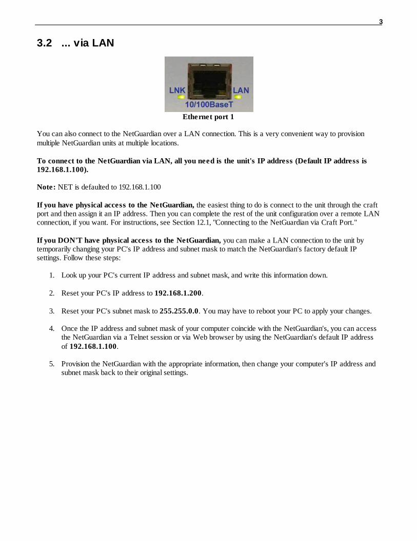
Ethernet port 1
You can also connect to the NetGuardian over a LAN connection. This is a very convenient way to provisionmultiple NetGuardian units at multiple locations.
To connect to the NetGuardian via LAN, all you need is the unit's IP address (Default IP address is192.168.1.100).
Note: NET is defaulted to 192.168.1.100
If you have physical access to the NetGuardian, the easiest thing to do is connect to the unit through the craftport and then assign it an IP address. Then you can complete the rest of the unit configuration over a remote LANconnection, if you want. For instructions, see Section 12.1, "Connecting to the NetGuardian via Craft Port."
If you DON'T have physical access to the NetGuardian, you can make a LAN connection to the unit bytemporarily changing your PC's IP address and subnet mask to match the NetGuardian's factory default IPsettings. Follow these steps:
1. Look up your PC's current IP address and subnet mask, and write this information down. 2. Reset your PC's IP address to 192.168.1.200. 3. Reset your PC's subnet mask to 255.255.0.0. You may have to reboot your PC to apply your changes. 4. Once the IP address and subnet mask of your computer coincide with the NetGuardian's, you can access
the NetGuardian via a Telnet session or via Web browser by using the NetGuardian's default IP addressof 192.168.1.100.
5. Provision the NetGuardian with the appropriate information, then change your computer's IP address andsubnet mask back to their original settings.

4
Web Interface4
Thet NetGuardian's Web Interface provides access to configure and monitor your NetGuardian.
Logging on to the NetGuardian4.1
Your NetGuardian must first be assigned an IP address via the TTY interface before you will be able to connectvia LAN/WAN using the Web Browser. If you have not yet done this, see Ethernet Port Setup in section (TTY Interface) of the hardware manual.
To connect to your NetGuardian:1. Type the IP address of the NetGuardian in your web browser's address bar2. Type your password in the password field that appears.
Note: The factory default password is dpstelecom.
Upon successfully logging in, you will be brought to the alarm summary screen in monitor mode.
The NetGuardian must be assigned an IP address before you will be able to connect via LAN/WAN using aTelnet client or a Web browser. To connect via LAN, the minimum configuration requires setup of the IP addressand subnet mask. Minimum WAN configuration requires that the default gateway be set as well. Follow theinstructions below to configure the NetGuardian's IP address, subnet mask, default gateway, trap address, SNMPport number, proxy base, and DHCP option.

5
Navigating the Web Interface4.2
The links in the left pane of the web interface allow you to navigate to the monitoring or editing screen you wish toview.
Only links for the mode of operation you are in will be visible in the navigation pane.
The web interface has two modes of operation:1. Monitor Mode , in which you may monitor your unit's alarms and issue controls. 2. Edit Mode , in which you may configure the unit
The unit defaults to Monitor Mode upon logging in. Clicking the green Edit button in the left pane of the webinterface will take you to Edit Mode. From Edit mode, you may revert to Monitor Mode by clicking the blue Monitor button.
Edit Mode4.3
Edit Mode provides the user access to all of the unit's configuration options.
If the Edit menu does not appear in the left frame after logging on, another station has already logged onas the primary user or you do not have access to edit the NetGuardian 420 database.

6
4.3.1 System Settings
From the System screen, you can enter basic user information for person responsible for the NetGuardian andconfigure basic settings for the unit.

7
Field Description
Name Used to set the Name of the Name@Location email address of the person responsible for theNetGuardian.Note: Name is the portion of the email address before the @ character.
Location Used to set the Location Name@Location email address of the person responsible for theNetGuardian.Note: Location is the portion after the @ character and should be a host name or an IP address.
Contact Provide information for how to contact the person responsible for this NetGuardian.
Phone Enter the contact's telephone number.
Features Used for entering feature codes for future upgrade features. Do not enter anything in this fieldunless so instructed by DPS Telecom
Unit ID Enter a user definable ID number for this NetGuardian (DCP Address).
DCP Port Enter the DCP Port for this NetGuardian. (1-8 serial otherwise UDP/IP Port) Note: DCPe added to the list of DCP protocols.
DCP Protocol Choose between DCPx, DCPf, or DCPe.
SCAN Unit ID The NetGuardian's unit address if responding to a SCAN interrogator (such as FarSCAN). Validvalues are 1-999. Use '0' to disable.
SCAN SerialPort
Select which serial port (1-4) on the NetGuardian will be used for SCAN communication.
Get history Download the unit's history file.
Silence non-reportable
system alarms
Check the box to silence alarms not applicable to your configuration. Example: This NetGuardianis not setup to send SNMP traps. Check this box to avoid receiving a failure notification forsystem alarm 13 (SNMP Trap not sent).
LCD PointMode
Check this box to have the front panel LCD operate in "Point Mode". In this mode, only the pointsin alarm are displayed on the screen, instead of the full alarm descriptions. Point numbers fordiscrete alarms, analog threshold crossings, and latched relays will appear on the LCD.
DNP Address This is the DNP3 polling address of the NetGuardian. This value can range from 0 -65519.
DNP TCP Port This option allows you to select the port for DNP3 polling over LAN. Set to "0" to disableDNP3
System fields
Once you've entered your information, click Submit Data to commit the data to the NetGuardian.
4.3.2 Defining SNMP Parameters
Access the Edit > SNMP link to view and edit your unit's SNMP settings.
To define your NetGuardian SNMP parameters:1. From the Edit menu choose SNMP.2. If you wish to restrict Read and Write Access to All, v1-Only, v2c-Only, or v3-Only, choose the
appropriate option from the drop down dialog box..3. Enter the community name for SNMP GET requests.4. Enter the community name for SNMP SET requests.5. Enter the community name for SNMP TRAPs.6. If using SNMPv3, enter usernames and access information in the v3-User's section.7. Define the IP address of your trap managers. Set to 255.255.255.255 if not using.8. Define the UDP port set by the SNMP managers to receive traps; usually 162.9. Select the Format in which you want your traps to be sent to your managers.

8
10. Click Submit to save your system information settings.
For more information on the above steps, see the field descriptions for the Edit SNMP screen in the table below.
SNMP Menu
Globals
Read and WriteAccess
This field defines how the NetGuardian unit may be accessed via SNMP. This can beset to the following:
· All- Allows you to read or write using any version of SNMP (v1, v2c, v3)
· Disabled- Restricts all access to unit via SNMP
· v1-Only- Allows SNMPv1 access only
· v2c-Only- Allows SNMPv2c access only
· v3-Only- Allows SNMPv3 access only
v3 Engine ID Specifies the v3 Engine ID for your NetGuardian device. DPS recommends using thedefault ID for the unit, which is automatically generated by the unit. The default ID isgenerated according to RFC3411 and is based on the unit's unique MAC address andDPS Telecom's SNMP enterprise number.Note: To have the unit generate a unique Engine ID, clear the v3 Engine ID field andpress the Submit key.
SNMP Communities
Get Community name for SNMP requests.
Set Community name for SNMP SET requests.
Trap / v3 Context Name
Community name for SNMP TRAP requests. In SNMP v3, defines the context namefield of a v3-Trap.
Note: Make sure that your community strings match those used by the SNMPmanager. In v1 and v2c, community strings are security passwords; if the strings do notmatch, the SNMP manager will not accept Traps from the NetGuardian. Community
9
strings are case sensitive.
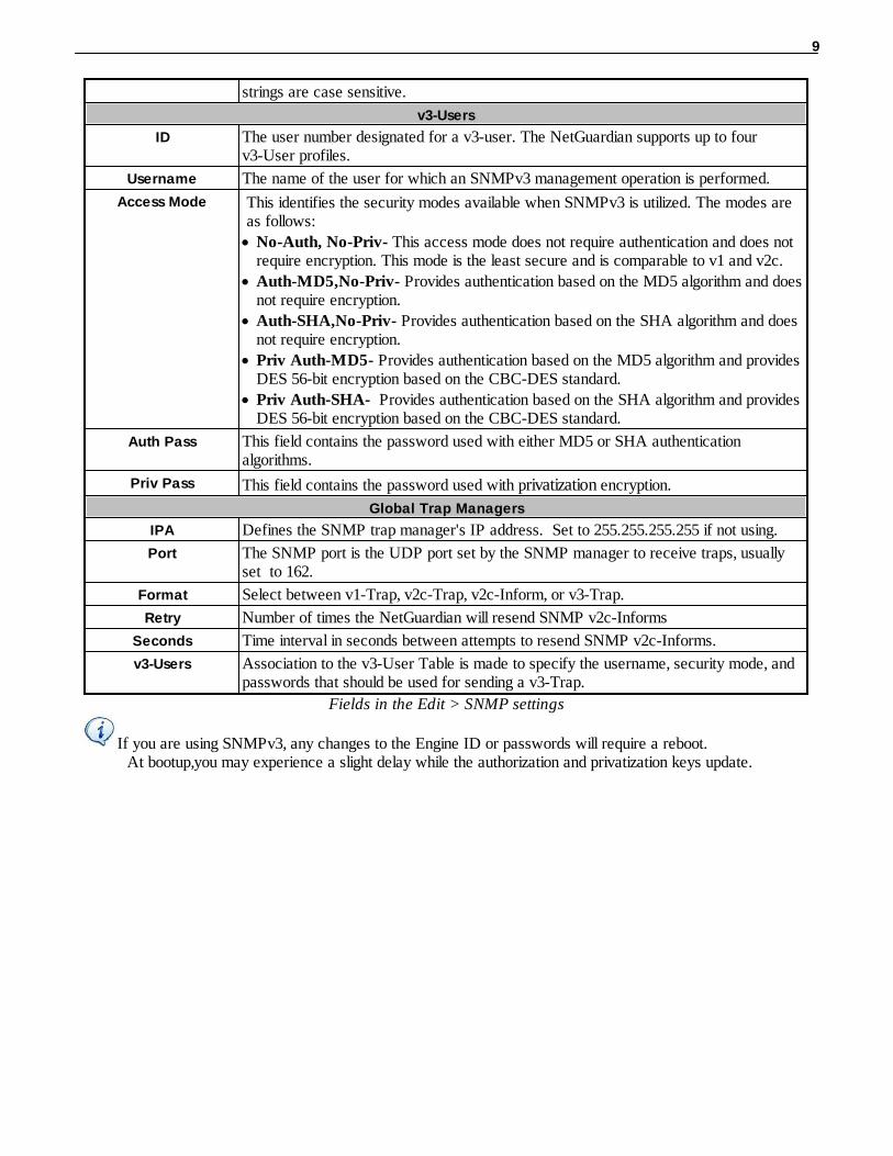
v3-Users
ID The user number designated for a v3-user. The NetGuardian supports up to four v3-User profiles.
Username The name of the user for which an SNMPv3 management operation is performed.
Access Mode This identifies the security modes available when SNMPv3 is utilized. The modes areas follows:
· No-Auth, No-Priv- This access mode does not require authentication and does notrequire encryption. This mode is the least secure and is comparable to v1 and v2c.
· Auth-MD5,No-Priv- Provides authentication based on the MD5 algorithm and doesnot require encryption.
· Auth-SHA,No-Priv- Provides authentication based on the SHA algorithm and doesnot require encryption.
· Priv Auth-MD5- Provides authentication based on the MD5 algorithm and providesDES 56-bit encryption based on the CBC-DES standard.
· Priv Auth-SHA- Provides authentication based on the SHA algorithm and providesDES 56-bit encryption based on the CBC-DES standard.
Auth Pass This field contains the password used with either MD5 or SHA authentication algorithms.
Priv Pass This field contains the password used with privatization encryption.
Global Trap Managers
IPA Defines the SNMP trap manager's IP address. Set to 255.255.255.255 if not using.
Port The SNMP port is the UDP port set by the SNMP manager to receive traps, usuallyset to 162.
Format Select between v1-Trap, v2c-Trap, v2c-Inform, or v3-Trap.
Retry Number of times the NetGuardian will resend SNMP v2c-Informs
Seconds Time interval in seconds between attempts to resend SNMP v2c-Informs.
v3-Users Association to the v3-User Table is made to specify the username, security mode, and passwords that should be used for sending a v3-Trap.
Fields in the Edit > SNMP settings
If you are using SNMPv3, any changes to the Engine ID or passwords will require a reboot. At bootup,you may experience a slight delay while the authorization and privatization keys update.
10
4.3.3 Controlling Access to the NetGuardian
4.3.3.1 Logon Settings
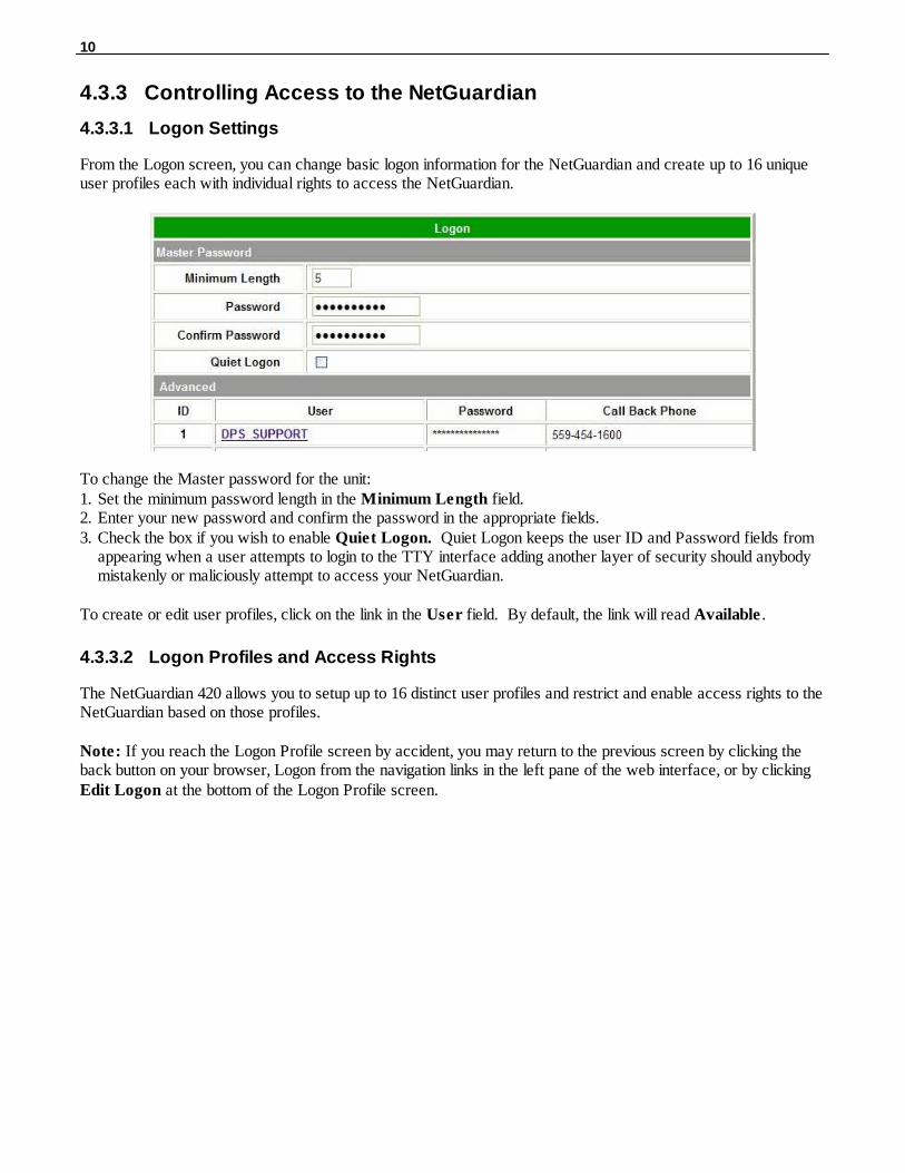
From the Logon screen, you can change basic logon information for the NetGuardian and create up to 16 uniqueuser profiles each with individual rights to access the NetGuardian.
To change the Master password for the unit:1. Set the minimum password length in the Minimum Length field. 2. Enter your new password and confirm the password in the appropriate fields.3. Check the box if you wish to enable Quiet Logon. Quiet Logon keeps the user ID and Password fields from
appearing when a user attempts to login to the TTY interface adding another layer of security should anybodymistakenly or maliciously attempt to access your NetGuardian.
To create or edit user profiles, click on the link in the User field. By default, the link will read Available .
4.3.3.2 Logon Profiles and Access Rights
The NetGuardian 420 allows you to setup up to 16 distinct user profiles and restrict and enable access rights to theNetGuardian based on those profiles.
Note: If you reach the Logon Profile screen by accident, you may return to the previous screen by clicking theback button on your browser, Logon from the navigation links in the left pane of the web interface, or by clicking Edit Logon at the bottom of the Logon Profile screen.

11
Logon Profile Configuration Screen
From the User Profile (1-16) screen, you can configure individual user profiles.1. Enter a User ID in the User field2. Enter and confirm the User's password in the appropriate fields3. In the Call Back feature, enter the phone number the NetGuardian will use to call-back the user's modem.4. Set Access Privileges for the user.
Profile Field Access Privilege Descriptions
Admin Enables the user to add/modify logon profiles and NetGuardian password information.
DB Edit Enables the user to perform database edits in the NetGuardian.
Monitor Enables the user to have Monitor access of the NetGuardian.
SDMonitor Enables the user to view serial port buffers.
Control Gives the user the ability to issue controls. This also automatically activates Monitor.
Reach-Through Enables the user to achieve reach-through (Proxy) access.
Modem Enables the user to call into the unit.
Telnet Enables the user to have Telnet access to the unit.
PPP Enables the user to access the PPP server with the user defined password.
Access Privilege descriptions
When you've finished creating or editing a user profile, click Submit Data.

12
4.3.3.3 Filter IPA Config and Operation
The Filter IPA table allows you to increase the NetGuardian's network security by allowing or blocking packetsfrom specified IP addresses. Addresses which appear in the table will be processed by the NetGuardian. DefinedIP addresses associated with network cameras or the network time server are automatically processed and willnot be filtered out by this feature. Broadcast packets of 255.255.255.255 and ARP requests for the NetGuardianIP address are also not filtered.
1. From the Edit menu select Filter IPA.2. A warning prompt will appear. Click OK to continue.
Filter IPA warning prompt
Select Filter IPA from the Edit menu to configure your Filter IPA table
3. Click the checkbox to Enable IPA Table.
4. Click the Block These Addresses if you wish to block only the addresses listed in the table. If you wish toallow only those IP Addresses listed in the table, do not check this box.
5. Enter the IP address of the machine(s) you would like to give access to the NetGuardian.6. Click Submit to save the configuration settings.
! Hot Tip!
Entering a zero in any of the octet fields will declare that part of the octet to be a wildcard.
WARNING: Does not work with networks that assign IP addresses. Use the wildcard field to open an entiresubnet.

13
4.3.3.4 Radius Authentication Settings
RADIUS (Remote Authentication Dial In User Service) is an industry-standard way to manage logins to manydifferent types of equipment in one central location. The NetGuardian 420 connects to your central RADIUSserver. Every time a device receives a login attempt (usually a username and password), it requests anauthentication from the RADIUS server. If the username & password combination is found in the server'sdatabase, an "access granted" reply is sent back to the unit, allowing the user to connect.
RADIUS configuration screen
RADIUS server prompt for Username andPassword.
To configure RADIUS authentication for your NetGuardian, input the appropriate information in the followingfields:
Global Settings
Retry Enter the number of times the RADIUS server should retry a logon attempt
Time-out Enter in the number of seconds before a logon request istimed out
Servers 1 / 2
IPA Enter the IP address of the RADIUS server
Port Port 1812 is an industry-standard port for using RADIUS
Secret Enter the RADIUS secret in this field
After successfully entering the settings for the RADIUS server, the NetGuardian Web Browser will prompt usersfor both a Username and Password, which will be verified using the information and access rights stored in theRADIUS database.
RADIUS logons are case-sensitive. If the RADIUS server is unavailable or access is denied, the masterpassword will work for craft port access only. Also, the "dictionary.dps" files (included on the Resource Disk)needs to be loaded on the RADIUS server for access-right definition. If RADIUS is enabled on the NetGuardian,local authentication will not be valid.

14
4.3.4 Ethernet Settings
From the Ethernet screen, you can configure information for your NetGuardian 420's ethernet ports.
To change Ethernet information, enter information in the appropriate fields and click Submit Data:
Field Description
Unit Address IP address of the NetGuardian
Subnet MaskA road sign to the NetGuardian telling it whether your packets should stay on yourlocal network or be forwarded somewhere else on a wide area network.
Default GatewayAn important parameter if you are on a network that is connected to a wide areanetwork. It tell the NetGuardian which machine is the gateway out of your localnetwork. Set to 255.255.255.255 if not using a gateway.
MAC Address Hardware address of the NetGuardian (not editable, for reference only).
DNS Address IP address of the domain name server. Set to 255.255.255.255 if not using.
Proxy Base
Defines the NetGuardian TCP ports used by data ports 1-8 (serial ports). Data port 1receives the port number entered here. Data ports 2-8 receive the next 7 port numbersin ascending order. (i.e. TCP port 3000 through port 3007 at the IP address of theNetGuardian).
HTTP Port Enter 80 if using HTTP, 443 if using HTTPS
DCHP Toggles the Dynamic Host Connection Protocol On or Off
Base URLThe Base URL is the destination website address or the alarm point descriptionhyperlinks. See Section "Using the Base URL Field."
Field Descriptions on the Ethernet Screen
4.3.4.1 Using the Base URL Field
The NetGuardian allows users to turn each alarm point description into a hyperlink. When utilized, the alarmdescription for each alarm point that appears in the monitor mode (for base alarms, ping targets, or system alarms)becomes a link that directs technicians/managers to specific Web pages or to other files viewable by a Webbrowser. This allows users to create easily accessible informational databases on how to handle specific alarmconditions or other instructions. The hyperlinked page or file will be displayed in the main window frame of theNetGuardian Web browser. Follow the directions below to create hyperlinks for alarm point descriptions.
1. From the Edit Menu select Ports. Scroll down to the Base URL field, see Figure 2.5.
15
2. Enter your base URL (e.g. http://www.dpstelecom.com). The NetGuardian creates the links from the alarmpoint descriptions based on the URL. Once the base URL is entered, the NetGuardian automatically attachesa unique suffix to each alarm point. For example, if the base URL is http://www.dpstelecom.com the link forthe base alarm at point 1 would be http://www.dpstele.com/base1.html, Base Alarm Point 2 would be http://
www.dpstele.com/base2.html, and so on.
3. To add a suffix other than html to the hyperlinks, insert the text &pntID; into the base URL. This allows theuser to specify the extension. For example, if the base URL is http://www.dpstele.com/&pntID;.pdf, the linkfor the base alarm at point 1 would be http://www.dpstele.com/base1.pdf/.
! Hot Tip! Any file type that is viewable in your Web browser (e.g. word document, PDF, txt, etc.) is a
linkable file.
4. The same link structure applies to the Ping Alarms, System Alarms, and Analog Alarms fields. See Table 2.Dfor specific URL extension link information.
Alarm Page Base URL web page link*
Base Alarms Base1.html - Base20.html
Ping Alarms Ping1.html - Ping32.html
System Alarms System1.html - System64.html
Analog Alarms Analog1.html - Analog8.html
Table 2.D. Specific link extensions* Using the &pntID; code in the base URL enables you to link to any file type viewable in your Web browser.
4.3.5 Configuring Ports
You'll configure your unit's modem and terminal server ports from the Edit menu > Ports screen.
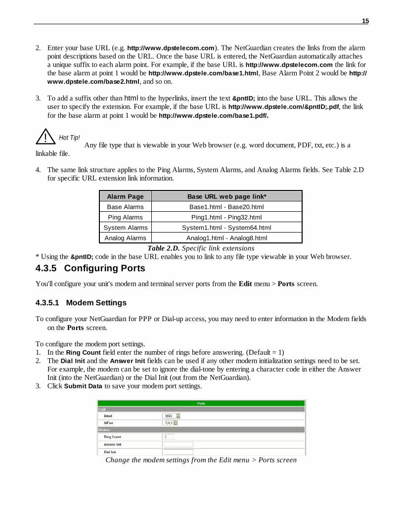
4.3.5.1 Modem Settings
To configure your NetGuardian for PPP or Dial-up access, you may need to enter information in the Modem fieldson the Ports screen.
To configure the modem port settings. 1. In the Ring Count field enter the number of rings before answering. (Default = 1)2. The Dial Init and the Answer Init fields can be used if any other modem initialization settings need to be set.
For example, the modem can be set to ignore the dial-tone by entering a character code in either the AnswerInit (into the NetGuardian) or the Dial Init (out from the NetGuardian).
3. Click Submit Data to save your modem port settings.
Change the modem settings from the Edit menu > Ports screen
16
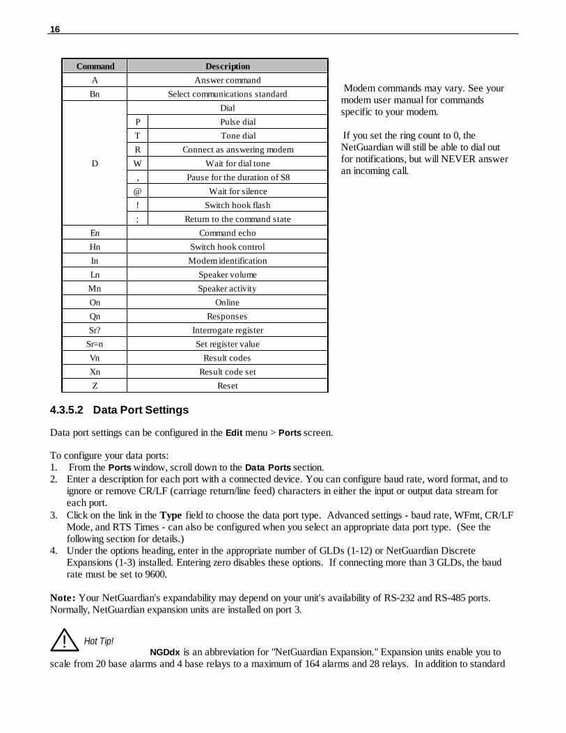
Command Description
A Answer command
Bn Select communications standard
D
Dial
P Pulse dial
T Tone dial
R Connect as answering modem
W Wait for dial tone
, Pause for the duration of S8
@ Wait for silence
! Switch hook flash
; Return to the command state
En Command echo
Hn Switch hook control
In Modem identification
Ln Speaker volume
Mn Speaker activity
On Online
Qn Responses
Sr? Interrogate register
Sr=n Set register value
Vn Result codes
Xn Result code set
Z Reset
Modem commands may vary. See yourmodem user manual for commandsspecific to your modem.
If you set the ring count to 0, theNetGuardian will still be able to dial outfor notifications, but will NEVER answeran incoming call.
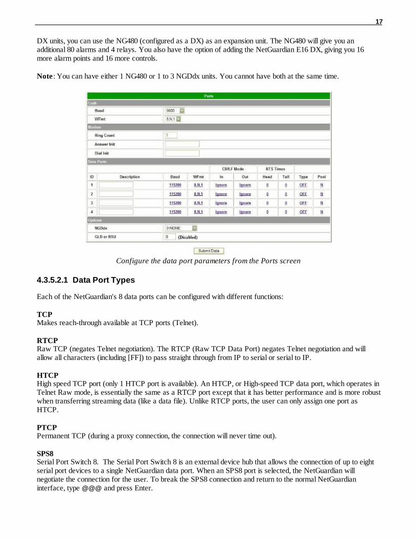
4.3.5.2 Data Port Settings
Data port settings can be configured in the Edit menu > Ports screen.
To configure your data ports:1. From the Ports window, scroll down to the Data Ports section.2. Enter a description for each port with a connected device. You can configure baud rate, word format, and to
ignore or remove CR/LF (carriage return/line feed) characters in either the input or output data stream foreach port.
3. Click on the link in the Type field to choose the data port type. Advanced settings - baud rate, WFmt, CR/LFMode, and RTS Times - can also be configured when you select an appropriate data port type. (See thefollowing section for details.)
4. Under the options heading, enter in the appropriate number of GLDs (1-12) or NetGuardian DiscreteExpansions (1-3) installed. Entering zero disables these options. If connecting more than 3 GLDs, the baudrate must be set to 9600.
Note: Your NetGuardian's expandability may depend on your unit's availability of RS-232 and RS-485 ports. Normally, NetGuardian expansion units are installed on port 3.
! Hot Tip!NGDdx is an abbreviation for "NetGuardian Expansion." Expansion units enable you to
scale from 20 base alarms and 4 base relays to a maximum of 164 alarms and 28 relays. In addition to standard
17
DX units, you can use the NG480 (configured as a DX) as an expansion unit. The NG480 will give you anadditional 80 alarms and 4 relays. You also have the option of adding the NetGuardian E16 DX, giving you 16more alarm points and 16 more controls.
Note : You can have either 1 NG480 or 1 to 3 NGDdx units. You cannot have both at the same time.
Configure the data port parameters from the Ports screen
4.3.5.2.1 Data Port Types
Each of the NetGuardian's 8 data ports can be configured with different functions:
TCPMakes reach-through available at TCP ports (Telnet).
RTCPRaw TCP (negates Telnet negotiation). The RTCP (Raw TCP Data Port) negates Telnet negotiation and willallow all characters (including [FF]) to pass straight through from IP to serial or serial to IP.
HTCPHigh speed TCP port (only 1 HTCP port is available). An HTCP, or High-speed TCP data port, which operates inTelnet Raw mode, is essentially the same as a RTCP port except that it has better performance and is more robustwhen transferring streaming data (like a data file). Unlike RTCP ports, the user can only assign one port asHTCP.
PTCPPermanent TCP (during a proxy connection, the connection will never time out).
SPS8Serial Port Switch 8. The Serial Port Switch 8 is an external device hub that allows the connection of up to eightserial port devices to a single NetGuardian data port. When an SPS8 port is selected, the NetGuardian willnegotiate the connection for the user. To break the SPS8 connection and return to the normal NetGuardianinterface, type @@@ and press Enter.

18
! Hot Tip!
SPS8 ports do not support direct proxy. You must navigate via the TTY menu. If interfacing a T/Mon to SPS8through a NetGuardian, set the port type to TCP.
UDPMakes reach-through available at UDP ports (up to 4 UDP ports available).
CHANCreates logical bridge to odd/even partner. The odd/even partners are pairs of 1-2 and 3-4. This allows theNetGuardian to view communication traffic in either direction when inserted in the serial communication pathbetween two devices. This is accomplished by going "in" to the NetGuardian with one device and "out" to the otherdevice from the odd/even partner port. Data is passed directly from one port to its odd/even partner without beingaltered in any way. This ability greatly simplifies troubleshooting communication problems by isolating the non-communicating device.
When CHAN is selected, the NetGuardian automatically activates the odd/even partner as CHAN. Baud rates forthe odd/even pairs can be set to any available rate except for any combination of 19200 and 38400 between thetwo ports. Use "SPO" filter debug to analyze protocol traffic in a terminal.
CRFTCauses the data port to have the same functionality as the front panel craft port.
CAPAllows the user to capture debug information. The debug information is stored in the receive queue of theNetGuardian (See section "Monitoring Data Port Activity" for more information). This is used primarily as atroubleshooting feature.
ECUFor use if an ECU is connected to this port (see section "Building Access Controller").
SCANCreates logical bridge between all ports set up as SCAN. When data comes in one port, it will forward out allother SCAN ports. The SCAN port defined under SCAN Serial Port will be the only port that will respond to scanpolls. The rest will only forward data.
MBSIAllows the use of the optional Cellguard Battery Monitoring System. When MBSI is selected, the NetGuardianautomatically sets the Description and Baud settings.
4.3.5.2.2 Direct and Indirect Proxy Connections
The NetGuardian supports both direct and indirect proxy connections. In a direct proxy connection, the user entersan IP address and port number to Telnet directly to a TCP serial port. In an indirect connection, the user navigatesthe TTY menu to select a proxy port. Because the TTY interface is password protected, thus providing greatersecurity, indirect connections are preferred. Some users prefer to disable direct proxy for all connections in orderto enforce the password security provided by the TTY interface.
To disable proxy connections you may either:1. Set the proxy port to an uncommon value. 2. Set the data ports to off in the Type field. When set to off, the port is no longer associated with a TCP socket,
which effectively disables the port from direct access. This is a more secure and convenient method ofdisabling proxy access.
19
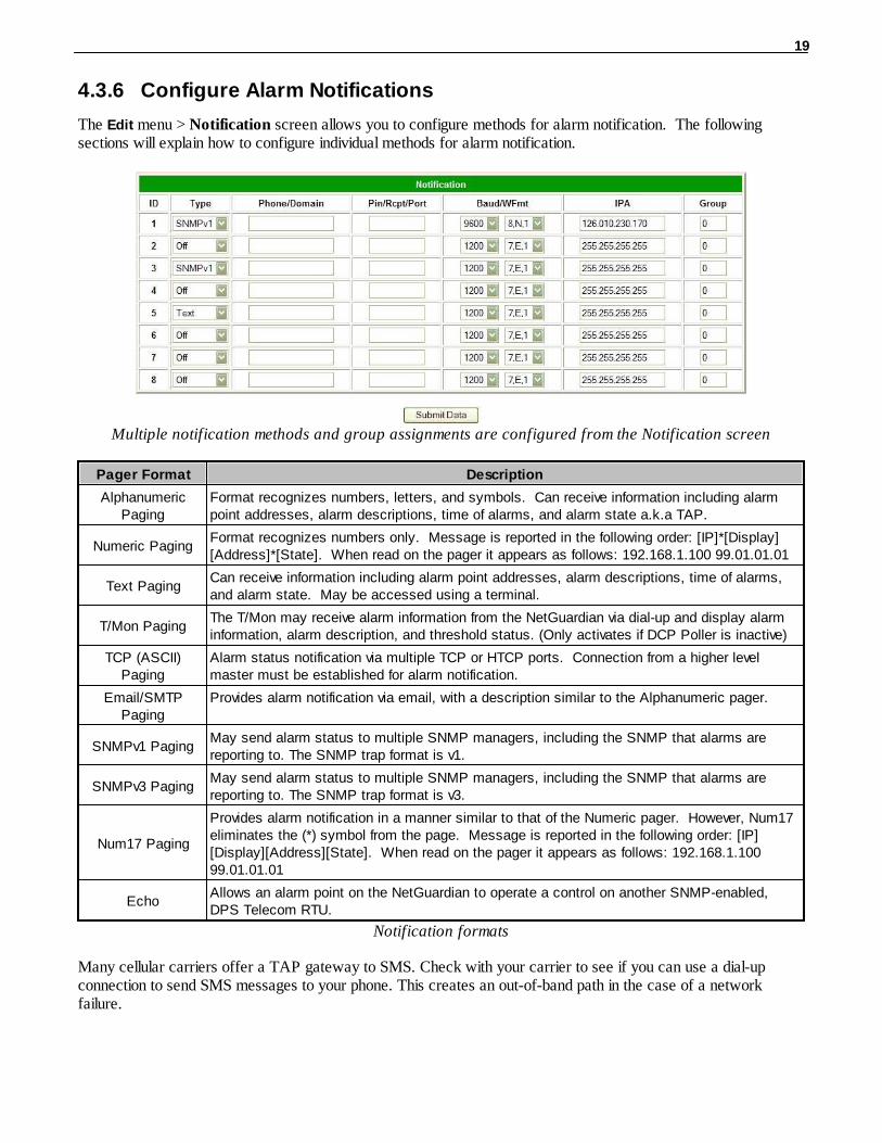
4.3.6 Configure Alarm Notifications
The Edit menu > Notification screen allows you to configure methods for alarm notification. The followingsections will explain how to configure individual methods for alarm notification.
Multiple notification methods and group assignments are configured from the Notification screen
Pager Format Description
AlphanumericPaging
Format recognizes numbers, letters, and symbols. Can receive information including alarmpoint addresses, alarm descriptions, time of alarms, and alarm state a.k.a TAP.
Numeric PagingFormat recognizes numbers only. Message is reported in the following order: [IP]*[Display][Address]*[State]. When read on the pager it appears as follows: 192.168.1.100 99.01.01.01
Text PagingCan receive information including alarm point addresses, alarm descriptions, time of alarms,and alarm state. May be accessed using a terminal.
T/Mon PagingThe T/Mon may receive alarm information from the NetGuardian via dial-up and display alarminformation, alarm description, and threshold status. (Only activates if DCP Poller is inactive)
TCP (ASCII)Paging
Alarm status notification via multiple TCP or HTCP ports. Connection from a higher levelmaster must be established for alarm notification.
Email/SMTPPaging
Provides alarm notification via email, with a description similar to the Alphanumeric pager.
SNMPv1 PagingMay send alarm status to multiple SNMP managers, including the SNMP that alarms arereporting to. The SNMP trap format is v1.
SNMPv3 PagingMay send alarm status to multiple SNMP managers, including the SNMP that alarms arereporting to. The SNMP trap format is v3.
Num17 Paging
Provides alarm notification in a manner similar to that of the Numeric pager. However, Num17eliminates the (*) symbol from the page. Message is reported in the following order: [IP][Display][Address][State]. When read on the pager it appears as follows: 192.168.1.10099.01.01.01
EchoAllows an alarm point on the NetGuardian to operate a control on another SNMP-enabled,DPS Telecom RTU.
Notification formats
Many cellular carriers offer a TAP gateway to SMS. Check with your carrier to see if you can use a dial-upconnection to send SMS messages to your phone. This creates an out-of-band path in the case of a networkfailure.

20
4.3.6.1 Alphanumeric Pager Setup
The alpha numeric pager can receive text messages including alarm descriptions, time of occurrence, and pointaddresses.
Use the following steps to configure the alpha numeric pager settings:1. Under the Type column, select type Alpha from the drop-down menu, see Figure 2.14.2. Enter the phone number of the Alpha numeric pager under the Phone/Domain heading.3. Enter a personal identification number under the PIN/Rcpt/Port heading.4. Set the pager data rate (i.e. 300, 1200, 2400 or 9600). The default baud is 1200.5. Select a pager word format (Data Bits, Parity, Stop Bits). The default setting is 7,Even,1.
1. Number of pages2. Unit name3. Port # and Address (Applicable to T/Mon and IAM only)4. Display number5. Alarm point number6. Alarm status: 1=alarm, 0=clear7. Time Net Guardian sent page8. Alarm point description9. Alarm status10. Time & date pager received
01: Net Guardian 1499.1.1.3.1 9:20TOWER LIGHTS Alarm
9:22 06/20/00
1 2
3
5 6
7
8 9
10
4
Alpha numeric pager description
4.3.6.2 SNPP Notification Setup
Alpha numeric pagers can receive text messages including alarm descriptions, time of occurrence, and pointaddresses using SNPP.
Use the following steps to configure the alpha numeric pager settings:.1. Under the Type column, select type SNPP from the drop-down menu.2. Use the Phone field if a login username and password are required. They must be separated by a colon and
be no longer than 29 characters combined. Otherwire, leave this field blank.3. Enter the numeric pager number under the PIN/Rcpt/Port heading.4. Under the IPA field, enter the static IPA of the SNPP server. Port automatically defaults to 444.
4.3.6.3 Numeric Pager Setup
The numeric pager can receive point addresses of alarms.
Use the following steps to configure the numeric pager settings:1. Under the Type column select Numeric from the drop-down menu.2. Enter the phone number of the numeric pager under the Phone/Domain heading, followed by 7 commas (e.g.
555-1212,,,,,,,). Placing a comma after the phone number initiates a two second pause (per comma). Thisallows enough time for the pager to answer before the NetGuardian sends the alarm information.
The Baud/Wfmt and IPA fields are not used from numeric pager types.

21
4.3.6.4 Text Paging Setup
Text pages can receive information including the point addresses of alarms, the alarm description, time of thealarm, and state (alarm or clear). The text pages may be viewed using a terminal such as HyperTerminal.
Use the following steps to configure the text paging settings:1. Under the Type column select Text from the drop-down menu.2. Enter the phone number of the text paging device under the Phone/Domain heading.3. Set the pager data rate (i.e. 300, 1200, 2400 or 9600). The default baud is 1,200.4. Select a pager word format (e.g Data bits: 7 or 8, Parity: none (N), even (E) or odd (O), and Stop Bits: 1).
The default setting is 7, Even,1.
To set up text paging from T/Mon see the T/Mon user manual.
4.3.6.5 Email Notification Setup
Email notification from the NetGuardian
The email pager provides alarm notification via email, with a description similar to that of the alpha-numeric pager.
1. Use the following steps to configure the email notification settings:2. Under the Type column, select Email from the drop-down menu.3. Enter the domain name of the email address under the Phone/Domain heading. This is the portion of an email
address after the @ symbol in [email protected]: There cannot be any spaces in the domain name.4. Enter the email recipient's user name under the PIN/Rcpt/Port heading. This is the portion of an email address
before the @ symbol in the [email protected]. Note: There cannot be any spaces in the recipient's user name5. Enter the IP address of the SMTP mail server in the IPA field.6. Click Submit Data to save your email notification settings. 7. Click on the System link. If you have not done so, set up the "from" address sent in email messages sent from
the NetGuardian by entering the appropriate information in the Name and Location fields. The emailnotification from the NetGuardian will appear as follows: name@location.
! Hot Tip!
Most email programs can be set to perform a certain action if a message is received from a specified address,such as moving the message to a special Alarms folder. Use the address entered in the Systems screen for suchpurposes.
8. Click Submit Data to save your new system information settings.
The "from" email address is for identification purposes. It is not necessarily a real email address that can
22
be replied to unless one is entered.
4.3.6.5.1 SMTP Support & POP3 Authentication Support
This section contains steps to configure your NetGuardian for SMTP and POP3 Authentication support.
Unauthenticated Emails:The configuration setup will not change. If you want the email to send to [email protected], use thefollowing steps:1. In the Phone/Domain field type yourdomain.com.2. In the Pin/Rcpt field type user.3. Click Submit Data to save the configuration settings.
The "from" location is specified by the system info name and location strings, which also do not change. Use thefollowing steps to configure the "from" location [email protected]:
1. Click on the Edit menu > System link.2. In the Name field type from.3. In the Location field type fromdomain.com.4. Click Submit Data to save the new system information settings.
Note: SMTP authentication is not supported.
Authenticated Emails (POP3 only):If you want to send an authenticated email to [email protected] from [email protected], password= authentic, then use the following steps:1. In the Pin/Rcpt field type authentic (the password). 2. In Phone/Domain field, type [email protected]. Click Submit Data to save your changes.4. Click on the Edit menu > System link for To information.5. In the Name field type user.6. In the Location field type yourdomain.com.
7. Click Submit Data to save the new system information settings.
4.3.6.6 SNMPv1 Paging Setup
The SNMPv1 paging feature allows you to view alarm status from multiple SNMP managers in addition to theglobal managers, which are setup from the SNMP menu.
Use the following steps to configure the SNMP paging settings:1. Under the Type column, select SNMPv1 from the drop-down menu.2. Set the SNMP port under the PIN/Rcpt/Port heading, usually 162.3. Enter the IP address of the SNMP manager in the IPA field.
4.3.6.7 SNMPv3 Paging Setup
The SNMPv3 paging feature allows you to view alarm status from multiple SNMP managers in addition to theglobal managers, which are setup from the SNMP menu.
Use the following steps to configure the SNMP paging settings:1. Under the Type column, select SNMPv3 from the drop-down menu.2. Enter a v3-User ID under the v3-User heading. The values can range from 0-4. These values refer to the v3-
Users table in the SNMP page. The v3-User association is used to specify username, security mode, and

23
passwords that should be used for sending a v3-Trap.3. Set the SNMP port under the PIN/Rcpt/Port heading, usually 162.4. Enter the IP address of the SNMP manager in the IPA field.
4.3.6.8 TCP Paging Setup
<MSG_BEG 00001>VID : DPS Telecom
FID : NetGuardian SNMP v5.0B.3206SITE: Yale OfficePNT : 99.01.01.01
DESC: RECTIFIER 1STAT: CLEAR
DATE: 01/01/2001TIME: 12:17:02
<MSG_END 00001>Fig. 2.17. Example TCP message
Heading Description
MSG_BEGMSG_END
Sequential message number used to group the message and detect missingmessages (e.g. 00001, 00002, etc...).
VID Vendor ID
FID NetGuardian Firmware ID.
SITE NetGuardian system name.
PNT Point ID (port.address.display.point). See Appendix A for display mapping.
DESC Description set forth in the Alarm parameters.
STAT Status of the alarm (Clear or Alarm).
DATE Date the alarm occurred.
TIME Time the alarm occurred.
Table 2.H. TCP alarm message field descriptions
The NetGuardian offers alarm status notification via multiple TCP ports. When an alarm condition occurs, analarm condition formatted according to Figure 2.17 will be sent to the specified TCP points for use by a higherlevel master. This connection must be established by the master. Any applicable alarm activity occurring prior toan established connection will be discarded.
Use the following steps to configure the TCP paging settings:1. Under the Type column, select TCP from the drop-down menu.2. In the Pin/Rcpt/Port field enter the NetGuardian TCP port number where alarm messages will be sent (from
1 to 65,536). Multiple ports can be defined by defining multiple pager IDs as TCP pagers and then entering thedesired ports.
3. The TCP message can be viewed by a Telnet session by connecting to the NetGuardian's IP address and theTCP port entered in this screen. For example, Telnet to 126.10.220.199 5000 if port 5000 is selected and126.10.220.199 is the unit's IP address. See Figure 2.17 for an example message and Table 2.H for TCPmessage format information.

24
4.3.6.9 NUM17 Pager Setup
The Num17 Pager can receive point addresses of alarms. It is quite similar to the Numeric Paging format in theway it receives and reports alarms. However, on certain pager systems the symbol * will cause a freeze or otherundesirable situations. Num17 eliminates the * symbol from the pages it receives and reports alarms as a 17-digitseries of numbers.
User the following steps to configure Num17 Pager settings:1. Under the Type column select Num17 from the drop-down menu.2. Enter the phone number of the numeric pager under the Phone heading, followed by commas (for example
555-1212,,,,,,,). Placing a comma after the phone number initiates a two second pause per comma. This allowsenough time for the pager to answer before the NetGuardian sends the alarm information. The Baud/Wfmt
and IPA fields are not used from Num17 pager types.3. Click Submit Data to save the configuration settings.
4.3.6.10 Echo Notification Setup
An Echo notification type enables an alarm point on the NetGuardian to operate a control on another SNMPremote from DPS.
1. From the Notification devices tab, choose Echo as the notification Type.2. Enter the Community Set Name in the Phone/Domain field.3. Enter the Relay Point Reference in the Pin/Pcpt/Port field. This is entered as:[Port].[Address].[Display].[Relay
Point] NOTE: The Port will always be 99, and the address is always 1. Therefore, your entries will alwaysbegin with 99.1.
4. The Baud/Wfmt and Group fields will not be used.5. Under IPA, enter in the IP address of the SNMP-enabled, DPS remote you are setting up to operate its relay.
NOTE: If more than one point is mapped to Echo notification, the OR'ed logic is applied.
4.3.7 Defining Point Groups
Each NetGuardian Alarm point can be assigned to one of eight groups, which are identified with a user-definedlabel. Once the point groups are defined, the Point Group IDs can be used to group base and system alarms, seesection "Configuring Base Discrete Alarms."
Use the following steps to define alarm messages for alarm point groups:1. To define the point groups, select Point Group from the Edit menu.2. Then enter the appropriate descriptions in the Description, When Set and When Clear fields for each point
group.3. Click Submit Data to save the point group settings.

25
Define the Alarm and Clear messages for up to eight different point groups
26
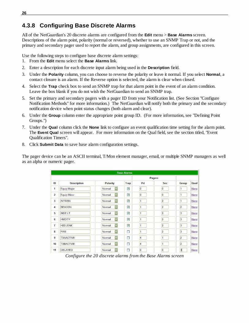
4.3.8 Configuring Base Discrete Alarms
All of the NetGuardian's 20 discrete alarms are configured from the Edit menu > Base Alarms screen.Descriptions of the alarm point, polarity (normal or reversed), whether to use an SNMP Trap or not, and theprimary and secondary pager used to report the alarm, and group assignments, are configured in this screen.
Use the following steps to configure base discrete alarm settings:1. From the Edit menu select the Base Alarms link.
2. Enter a description for each discrete input alarm being used in the Description field.
3. Under the Polarity column, you can choose to reverse the polarity or leave it normal. If you select Normal, acontact closure is an alarm. If the Reverse option is selected, the alarm is clear when closed.
4. Select the Trap check box to send an SNMP trap for that alarm point in the event of an alarm condition.Leave the box blank if you do not wish the NetGuardian to send an SNMP trap.
5. Set the primary and secondary pagers with a pager ID from your Notification list. (See Section "ConfigureNotification Methods" for more information.) The NetGuardian will notify both the primary and the secondarynotification device when point status changes (both alarm and clear).
6. Under the Group column enter the appropriate point group ID. (For more information, see "Defining PointGroups.")
7. Under the Qual column click the None link to configure an event qualification time setting for the alarm point.The Event Qual screen will appear. For more information on the Qual field, see the section titled, "EventQualification Timers".
8. Click Submit Data to save base alarm configuration settings.
The pager device can be an ASCII terminal, T/Mon element manager, email, or multiple SNMP managers as wellas an alpha or numeric pager.
Configure the 20 discrete alarms from the Base Alarms screen

27
4.3.9 Configuring System Alarms
SNMP Traps and primary or secondary pager devices can be selected for each system alarm
The System Alarms screen allows you to individually set the notification method for each system alarm. See the"System Alarms Display Map" in the Reference Section for detailed descriptions of System Alarm Points.
To configure your system alarm notification settings:1. From the Edit menu select the System Alarms link.2. Check the Trap box to send an SNMP trap for that alarm point. 3. Set the primary and secondary pagers with a Notification ID from your defined notification list. (See Section
"Configure Alarm Notifications" for more information.)Note: The NetGuardian will notify both the primary and the secondary notification device when point status
changes (both alarm and clear).4. Under the Group column enter the appropriate Point Group ID, see section.5. Click Submit Data to save the configuration settings.

28
4.3.10 Setting Ping Targets
Fig. 2.23. Configure the ping target parameters from the Ping Info screen
Each of the 32 ping targets can be provisioned with a description, an IP address, primary and secondarynotification devices, and an option to verify connection using SNMPv1 GET.
Note: To set ping response and fail times, see the section titled Setting System Timers .
To configure the ping targets:1. From the Edit menu select Ping Targets..2. In the Description field, enter a description of the device to be pinged.3. In the IP Address field enter the IP address of the device to be pinged.4. Under the Trap column check the box to designate that an SNMP trap will be sent when an alarm condition
exists. Leaving the box blank indicates that an SNMP trap will not be sent when an alarm condition exists.5. Set the primary and secondary pagers with a Notification ID from your defined Notification list. Note: The NetGuardian 420 will notify both the primary and the secondary notification device when point status
changes (both alarm and clear).6. Under the Group column enter the appropriate Point Group ID.7. Under the SNMP column check the box to enable pinging of the device using SNMPv1 GETs instead of
traditional ICMP. If the box is not checked, the device will be pinged using traditional ICMP.8. Select the OID to retrieve with the SNMP GET. The following is a list of available MIB variables in the System
OID field:sysDescr, OID .1.3.6.1.2.1.1.1.0sysObjectID, OID .1.3.6.1.2.1.1.2.0SysUpTime, OID .1.3.6.1.2.1.1.3.0
9. In the Community field enter the community string for the SNMP GET request.The community string mustmatch the community string configured in the target device.
10. Click Submit Data to save the configuration settings.
29
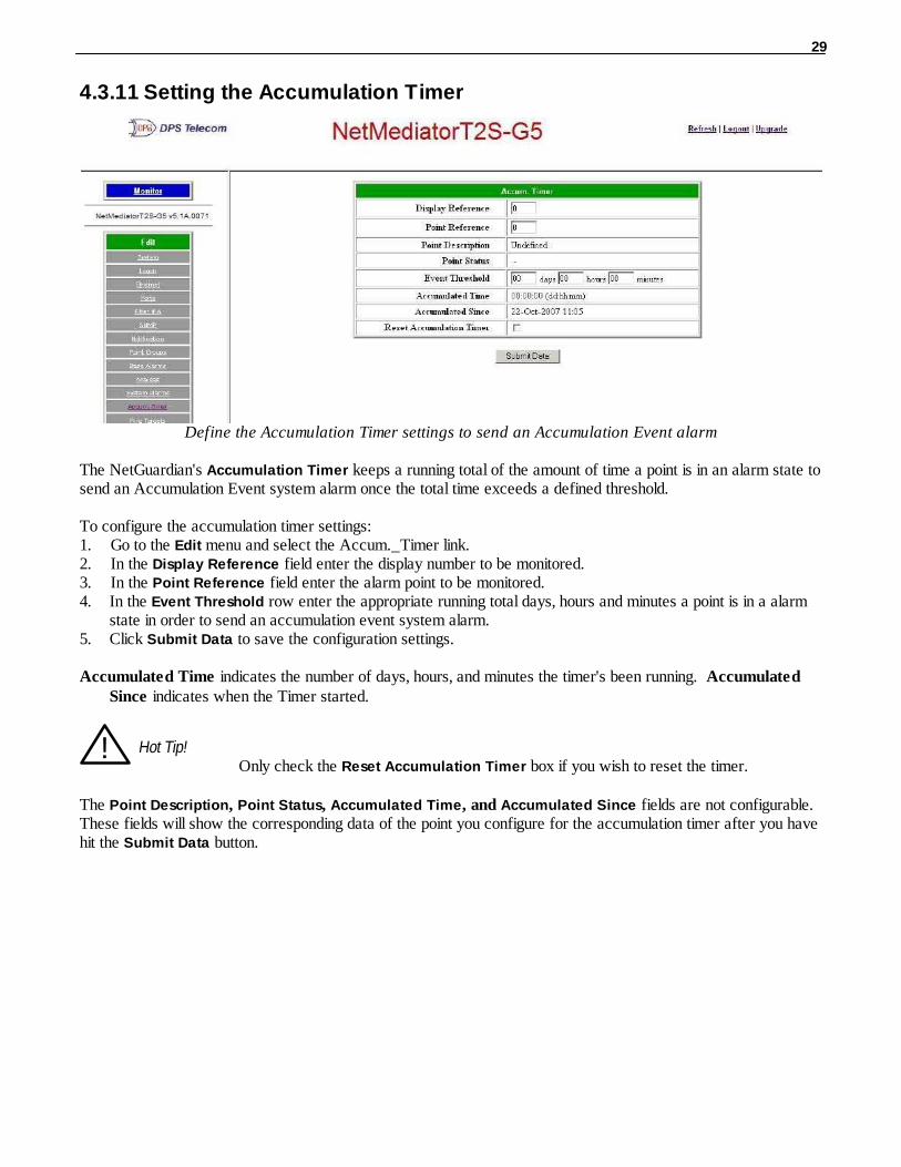
4.3.11 Setting the Accumulation Timer
Define the Accumulation Timer settings to send an Accumulation Event alarm
The NetGuardian's Accumulation Timer keeps a running total of the amount of time a point is in an alarm state tosend an Accumulation Event system alarm once the total time exceeds a defined threshold.
To configure the accumulation timer settings:1. Go to the Edit menu and select the Accum._Timer link.2. In the Display Reference field enter the display number to be monitored.3. In the Point Reference field enter the alarm point to be monitored.4. In the Event Threshold row enter the appropriate running total days, hours and minutes a point is in a alarm
state in order to send an accumulation event system alarm.5. Click Submit Data to save the configuration settings.
Accumulated Time indicates the number of days, hours, and minutes the timer's been running. AccumulatedSince indicates when the Timer started.
! Hot Tip!Only check the Reset Accumulation Timer box if you wish to reset the timer.
The Point Description, Point Status, Accumulated Time, and Accumulated Since fields are not configurable.These fields will show the corresponding data of the point you configure for the accumulation timer after you havehit the Submit Data button.

30
4.3.12 Configuring Analogs
Each of the NetGuardian 420's analog channels must be individually configured to monitor data. The ADCs(analog to digital converters) support a range of –70 to 94 VDC. There are four alarm trip points (thresholds) inascending order: major under, minor under, minor over, and major over. You can choose the values for each of thethresholds on all channels. As with the other alarms, you can designate whether or not to send an SNMP trapwhen a threshold is crossed. The primary/secondary pager used to report the alarm is also set here. The thresholdsmust be set from Under to Over in either ascending or descending potential (or current) order. Thus the settings of–10, –5, 5 and 10 corresponding respectively to major under, minor under, minor over and major over is valid.
The analog alarms are set to measure voltage by default and the thresholds are reported as "native units." Forexample, you may set Channel 3 to measure outside temperature. If you were using a sensor with a measurabletemperature range between –4° to 167° Fahrenheit (–20° to 75° Celsius). The voltage for that channel variesbetween 1 and 5 VDC for that sensor, which is to be reported as ° Fahrenheit (native units) where 1 voltrepresents –4° Fahrenheit and 5 volts represents 167° Fahrenheit.
To change any one analog alarm to measure current instead, a dip switch setting must be changed. Refer to theNetGuardian hardware user manual for details on jumper locations and positions. The jumper inserts a 250 ohmshunt resistor across the input to convert the sensors current output to volts. Use ohms law to find the voltage dropacross the 250 ohm shunt resistor (multiply the current by the resistance 250 ohms). Please refer to the operationmanual for your sensor to determine any other conversion factors. This will allow you to correctly set thethresholds for over and under conditions.
The Analog Parameters can be viewed and changed from the Analogs screen
NOTE: To configure the gauge type, select the link in the 'Unit' column. From here you can select which gauge(or none at all) you want displayed under Base Analogs in Monitor Mode.
1. From the Edit menu click on the Analogs link.2. In the Description field enter a description for each analog channel being utilized. 3. Under the Unit column, click on the abbreviated units link (e.g VDC, RH, F, etc.).4. Set Reference 1 (VDC) to the minimum output (in volts DC) of the analog device being configured.5. In the box next to VDC (the space may already contain the abbreviation VDC) enter an abbreviation for the
native units (e.g. RH for relative humidity, F for ° Fahrenheit, etc.).

31
6. In the box below the abbreviated native unit setting enter the native unit amount that corresponds to theminimum output entered in the previous step.
7. Set Reference 2 (VDC) to the maximum output (in volts DC) of the analog device being configured.8. In the box next to VDC enter an abbreviation for the native units (e.g. RH for relative humidity, F for °
Fahrenheit, etc.).9. In the box below the abbreviated native unit setting enter the native unit amount that corresponds to the
maximum output entered in the previous step.10. Enter the Point Group ID designated for each alarm level (MjU = Major Under, MnU = Minor Under, MjO =
Major Over, MnO = Minor Under). 11. Check the 'Polarity' checkbox if you want the polarity set to 'Normal' or 'Reversed'. When set to 'Reversed',
the polarity of the analog reading will be changed (positive to negative and negative to positive).12. Check the 'Associate enable/disable to base alarm #' if you want the analog channel to be tied to the base
discrete point of the same number (i.e. channel 5 with alarm 5). When in this mode, the analog is onlyenabled when the associated alarm point is set.
13. Select which type of gauge best represents your data. This is the gauge type that will be displayed whenviewing Base Analogs in Monitor Mode. Selecting 'None' will cause the Base Analogs display in MonitorMode to display the analog value instead of a gauge. Set all channels to 'None' to default the analog display toTable View. Gauge support is only supported with the xFLSH hardware option.
14. Click the Submit Data button to save the configuration settings.15. Follow these steps for each analog channel being configured.
Reference 1 and reference 2 correspond to the minimum and maximum output values of your analog device
4.3.12.1 Integrated Temperature and Battery Sensor (Optional)
The optional integrated temperature and battery sensor allows the user to monitor surrounding temperature as wellas the unit's current draw. This is only available if the NetGuardian was purchased with this option. If you areusing the temperature or battery sensor, you must dedicate an analog port to each one (see user manual forconnection information).
CAUTION: Ambient room temperature will be cooler than the NetGuardian integrated temperature.
Temperature Sensor1. In the Description field enter a description in the analog channel you are using for the integrated temperature
sensor. 7=internal and 8=external.2. Under the Unit column, click on the abbreviated units link (e.g VDC, RH, F, etc.) to convert the reference
units and the native units for that analog channel, see Figure 2.24.3. In Reference 1 enter iF (integrated Fahrenheit or external Fahrenheit) in the box next to VDC (the space may
already contain the abbreviation VDC), see Figure 2.24. This enables the NetGuardian's pre-configuredtemperature settings. Repeat this step for Reference 2.
4. Set your desired thresholds.
Battery Sensor1. In the Description field enter a description in the analog channel you are using for the integrated current

32
sensor. 5= Battery A and 6= Battery B. 2. Set your desired thresholds. Be sure to set your thresholds in reference to your NetGuardian's power input
(e.g. –24 VDC, –48 VDC, or wide range).
4.3.12.2 D-Wire Sensors
Fig. 2.28. D-Wire Sensors menu
If this NetGuardian has support for D-Wire sensors, their configuration links will appear in the Edit menu. Theinterface will resemble that of the regular analog pages, with the difference being a new column for the ROMID'sof each sensor. Any detected or configured sensor will appear in this column. The color of each ROMID's cellin the table will depend on its detected status. If the cell is yellow, that sensor is detected but is not yet configured. The page must be submitted in order to configure these detected ROMIDs. Once submitted, all of the settingsmentioned in the previous section will apply to this sensor (the "Unit" field will automatically be configured uponsubmission, no changes should be made to this field for D-Wire sensors). If the cell is red, then the sensor isconfigured but has not been detected. The D-Wire Sensor Not Detected System Alarm will set if any configuredsensor is not detected. The Freq. column determines how often (in minutes) the unit logs each sensor to a .csvfile.
Note : It may take up to one minute for a newly attached sensor to register in the Edit or Monitor interface.
Note: In T/Mon when defining the D-Wire temperature sensors use "iF" for the unit value. For D-Wire humiditysensors, set the Voltage Value 1 to 1, the Unit Value 1 to 5.5238, Voltage Value 2 to 4 and Unit Value 2 to100.762"
4.3.12.3 Analog Polarity Override
eF : external temperature sensor in fahrenheit or iC for celsius iF : integrated temperature sensor in fahrenheit or iC for celsius oV+ : override polarity VDC to positiveoV- : override polarity VDC to negative
If you have a positive powered NetGuardian, you may want to use this feature if you are using the internal batterysensor. The Web Browser Interface will override oV+ and oV- tags and show VDC. So you won't have to viewan uncommon looking tag while in monitor mode.
Analog Accuracy: +/- 1% of analog range.

33
4.3.12.4 Analog Step Sizes
Analog Step Sizes
Input Voltage Range Resolution (Step Size)
0-5 V .0015 V
5-14 V .0038 V
14-30 V .0081 V
30-70 V .0182 V
70-90 V .0231 V
Analog step sizes

34
4.3.13 Configuring Control Relays
Configure controls in the Edit menu > Controls screen
The NetGuardian 420's 3 or 4 relays (depending on build option) can be identified and configured using the Edit
menu > Controls screen.
Relays are normally open (N/O) by default. A circuit board jumper can be changed for each control to make itnormally closed (N/C). Refer to
To configure your relays:
1. From the Edit menu, select the Controls link.2. In the Description field enter a description for each control/relay being used.3. Set the Energize State to either Normal or Inverted. Selecting Normal sets the relay's normal electrical
state to De-energized. Selecting Inverted sets the relay's normal electrical state to Energized.4. Check the Trap box to send an SNMP trap for that alarm point. Selecting the box will set that point to send a
SNMP trap when the relay is activated, leaving the box blank will set that point to not send an SNMP trap. 5. Under the Group column enter the appropriate Point Group ID6. Click Submit Data to save the configuration settings.
! Hot Tip!
The Energize State is different than the normal state of the physical contact closure position of each relay, which isdetermined by circuit board jumpers. This gives you the added benefit of being able to monitor the wire. In theevent of a power failure, the relay would de-energize back to it's normal physical contact closure set by the circuitboard jumper for that relay. Check your jumper settings and relay connections before setting to Normal orInverted.
35
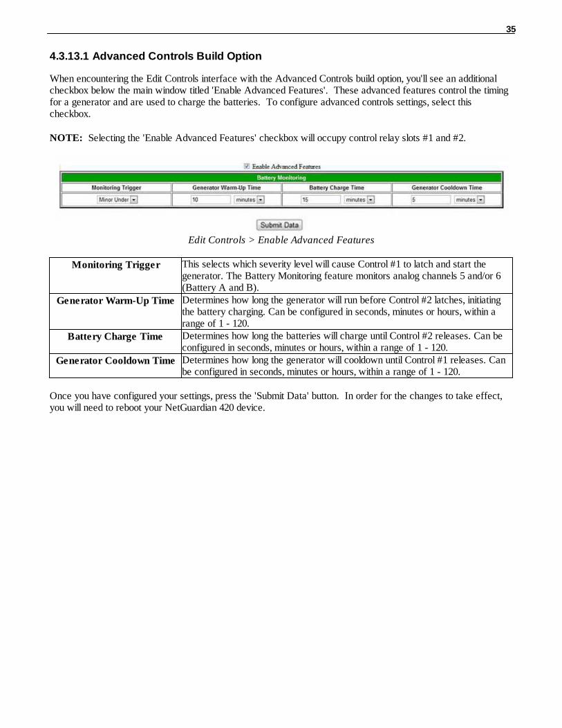
4.3.13.1 Advanced Controls Build Option
When encountering the Edit Controls interface with the Advanced Controls build option, you'll see an additionalcheckbox below the main window titled 'Enable Advanced Features'. These advanced features control the timingfor a generator and are used to charge the batteries. To configure advanced controls settings, select thischeckbox.
NOTE: Selecting the 'Enable Advanced Features' checkbox will occupy control relay slots #1 and #2.
Edit Controls > Enable Advanced Features
Monitoring Trigger This selects which severity level will cause Control #1 to latch and start thegenerator. The Battery Monitoring feature monitors analog channels 5 and/or 6(Battery A and B).
Generator Warm-Up Time Determines how long the generator will run before Control #2 latches, initiatingthe battery charging. Can be configured in seconds, minutes or hours, within arange of 1 - 120.
Battery Charge Time Determines how long the batteries will charge until Control #2 releases. Can beconfigured in seconds, minutes or hours, within a range of 1 - 120.
Generator Cooldown Time Determines how long the generator will cooldown until Control #1 releases. Canbe configured in seconds, minutes or hours, within a range of 1 - 120.
Once you have configured your settings, press the 'Submit Data' button. In order for the changes to take effect,you will need to reboot your NetGuardian 420 device.

36
4.3.14 Setting Event Qualification Timers
Event qualification timers allow you to determine a length of time that must pass before an event can occur. Forexample: you may set a qualification timer that requires an alarm to be set for five seconds before it is reported.
Edit the Even Qualification Timer settings from the Edit > Even Qual screen
To configure Event Qual timers:1. From the Edit menu select from the Event Qual drop down menu. The NetGuardian supports up to 128 Event
Qualification Timers, which are grouped into sections of sixteen.2. Enter the display and point number for the point you wish to qualify.Note: the ID will correspond to Event Qualification. A list of displays and points can be found in Appendix B.3. In the Value field enter the appropriate value (the field handles entries between 1 - 127).4. Under the Units column, click on the drop-down menu and select the appropriate unit of time (sec, min, hour).5. Under the Type column click on the drop-down menu and select the appropriate event type (Alm = alarm, Pri
= primary, Sec = secondary).Note: To delete an entry, set the Type to None.6. When you are done making changes, scroll to the bottom of the page and click Submit Data.
CAUTION: Set conditions for alarms are qualified, clear conditions are not.
By referencing a control relay in the display and point fields, an event becomes a momentary relay time. Controlsare mapped to Display 11, Points 1-4. See the Reference Section of this manual for display mapping information.
37
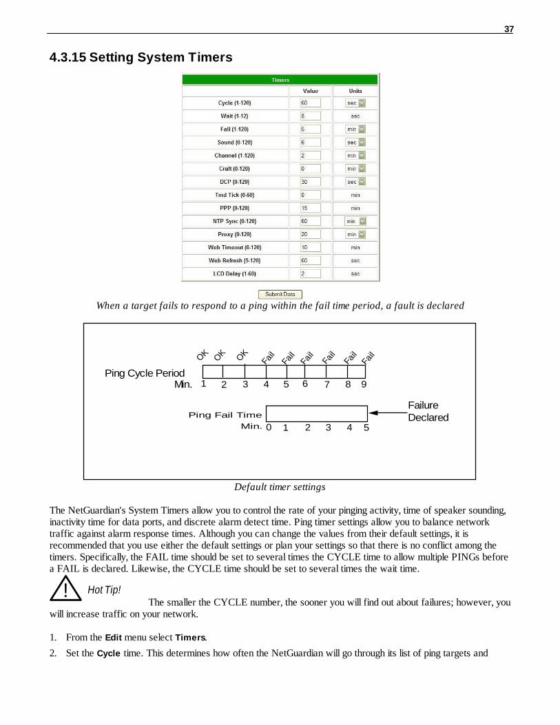
4.3.15 Setting System Timers
When a target fails to respond to a ping within the fail time period, a fault is declared
Ping Cycle Period
Ping Fail Time
Min.
FailureDeclared
OK
OK
OK
Fail
Fail
Fai
l
Fai
l
Fai
l F
ail
21 3 4 5 7 6 8 9Min.
0 1 2 3 4 5
Default timer settings
The NetGuardian's System Timers allow you to control the rate of your pinging activity, time of speaker sounding,inactivity time for data ports, and discrete alarm detect time. Ping timer settings allow you to balance networktraffic against alarm response times. Although you can change the values from their default settings, it isrecommended that you use either the default settings or plan your settings so that there is no conflict among thetimers. Specifically, the FAIL time should be set to several times the CYCLE time to allow multiple PINGs beforea FAIL is declared. Likewise, the CYCLE time should be set to several times the wait time.
! Hot Tip!The smaller the CYCLE number, the sooner you will find out about failures; however, you
will increase traffic on your network.
1. From the Edit menu select Timers.
2. Set the Cycle time. This determines how often the NetGuardian will go through its list of ping targets and

38
attempts to reach them with an ICMP ping. Set the value between zero and 120 and set the units to eitherseconds or minutes. Default is 60 seconds.
3. Set the Wait time. The NetGuardian waits after sending a ping request before it determines that the target isunreachable. Set the value between zero and 12 and set the units to either seconds or minutes. Default is 8seconds.
4. Set the Fail time. This determines the period of time over which, if a unit has not responded, it is consideredfailed. Set the value between zero and 120 and set the units to either seconds or minutes. Default is 5 minutes.
5. Set the Sound time. This determines how long the NetGuardian's speaker will sound when an alarm occurs orclears. The alarm condition will still be present after the speaker shuts off. The sound timer only affects theduration of the audible alarm annunciation. Set the value between zero and 120 and set the units to eitherseconds or minutes.
6. Set the Channel time. This determines the period of time over which, if there is no activity on the data portsdesignated as channel ports, it is considered failed. Set the value between zero and 120 and set the units toeither seconds or minutes. Alarm activity is indicated in Display 11, Point 62. (See Appendix A, "DisplayMapping.")
7. Set the Craft time. This determines the period of time over which, if the device connected through a portdesignated as a craft port doesn't reset the timer, an alarm will be triggered. Set between 0 and 120 (min orsec). Alarm activity is indicated in Display 11, Point 63. (See Appendix A, "Display Mapping.")
8. Set the DCP time. Set between 0–120 (sec or min). This determines the period of time over which, if theNetGuardian does not receive a DCP poll, to trigger an alarm. Once the alarm is triggered, then dial back-upmay be enabled if a T/Mon pager profile is configured.
9. Set the Timed Tick between 0–60 minutes. This is a "keep alive or heartbeat" function that can be used byMasters who don't perform integrity checks. For example, if you entered 30, the NetGuardian would notifyyou every 30 minutes. See section "Setting Up Notification Methods" for paging information.
10. Set the PPP time. Set between 0–120 for onDemand mode.
11. Set the NTP Sync. Set between 0–120 (sec or min).
Note: The timer settings are accurate to ± one tick. This means that if a timer is set to one minute, it may actuallyrespond anywhere from zero to two minutes. If your target time is one minute, then set the timer to 60 seconds sothat it will respond anywhere from 59-61 seconds.12. Set the Proxy time between 0-120 minutes. This indicates the length of time that has to pass before a proxyconnection times-out from inactivity.13. Set the Web Edit Timeout time between 5–120 minutes. This determines the period of time a Web edit page
may be active without any activity. A logon is required if a Web edit timeout occurs. The default Web edittime is 10 mins.
Note: The time units are preset to minutes by default and cannot be changed.
14. Set the Web Monitor Refresh time between 5–120 seconds. This timer enables the user to specify how longthe NetGuardian should wait before auto-refreshing a Monitor page to the Web browser. The default Webmonitor refresh time is 60 seconds.
Note: The time units are preset to seconds by default and cannot be changed.
15. Set the LCD Delay time between 1–60 seconds. This timer is used when you have set the LCD to "PointMode." This time is how long you want the alarm to be displayed on the front panel LCD screen. The defaultis 2 seconds.
16. Set the LCD Scroll speed between 100 to 1000 milliseconds. This timer is used to configure how much timepasses for the LCD to continue scrolling. The default is 600 milliseconds.
39
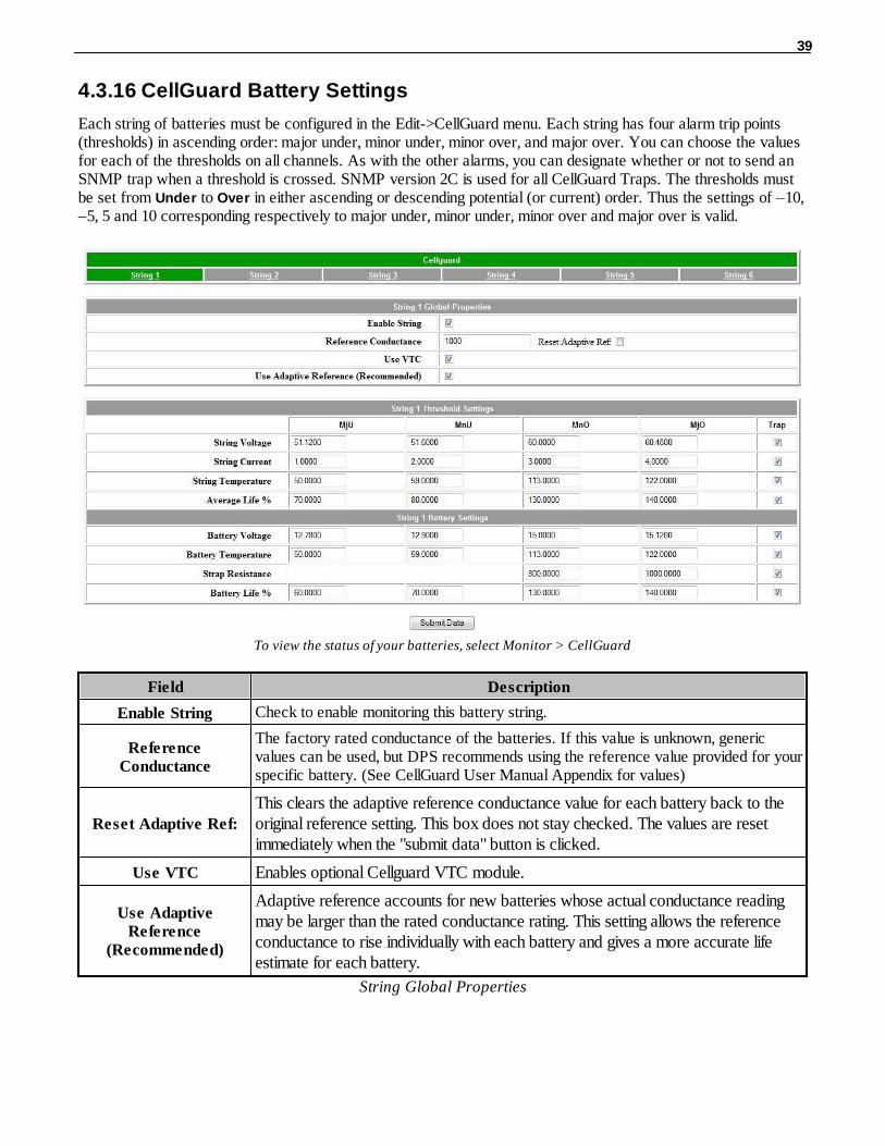
4.3.16 CellGuard Battery Settings
Each string of batteries must be configured in the Edit->CellGuard menu. Each string has four alarm trip points(thresholds) in ascending order: major under, minor under, minor over, and major over. You can choose the valuesfor each of the thresholds on all channels. As with the other alarms, you can designate whether or not to send anSNMP trap when a threshold is crossed. SNMP version 2C is used for all CellGuard Traps. The thresholds mustbe set from Under to Over in either ascending or descending potential (or current) order. Thus the settings of –10,–5, 5 and 10 corresponding respectively to major under, minor under, minor over and major over is valid.
To view the status of your batteries, select Monitor > CellGuard
Field Description
Enable String Check to enable monitoring this battery string.
ReferenceConductance
The factory rated conductance of the batteries. If this value is unknown, genericvalues can be used, but DPS recommends using the reference value provided for yourspecific battery. (See CellGuard User Manual Appendix for values)
Reset Adaptive Ref:
This clears the adaptive reference conductance value for each battery back to theoriginal reference setting. This box does not stay checked. The values are resetimmediately when the "submit data" button is clicked.
Use VTC Enables optional Cellguard VTC module.
Use AdaptiveReference
(Recommended)
Adaptive reference accounts for new batteries whose actual conductance readingmay be larger than the rated conductance rating. This setting allows the referenceconductance to rise individually with each battery and gives a more accurate lifeestimate for each battery.
String Global Properties
40
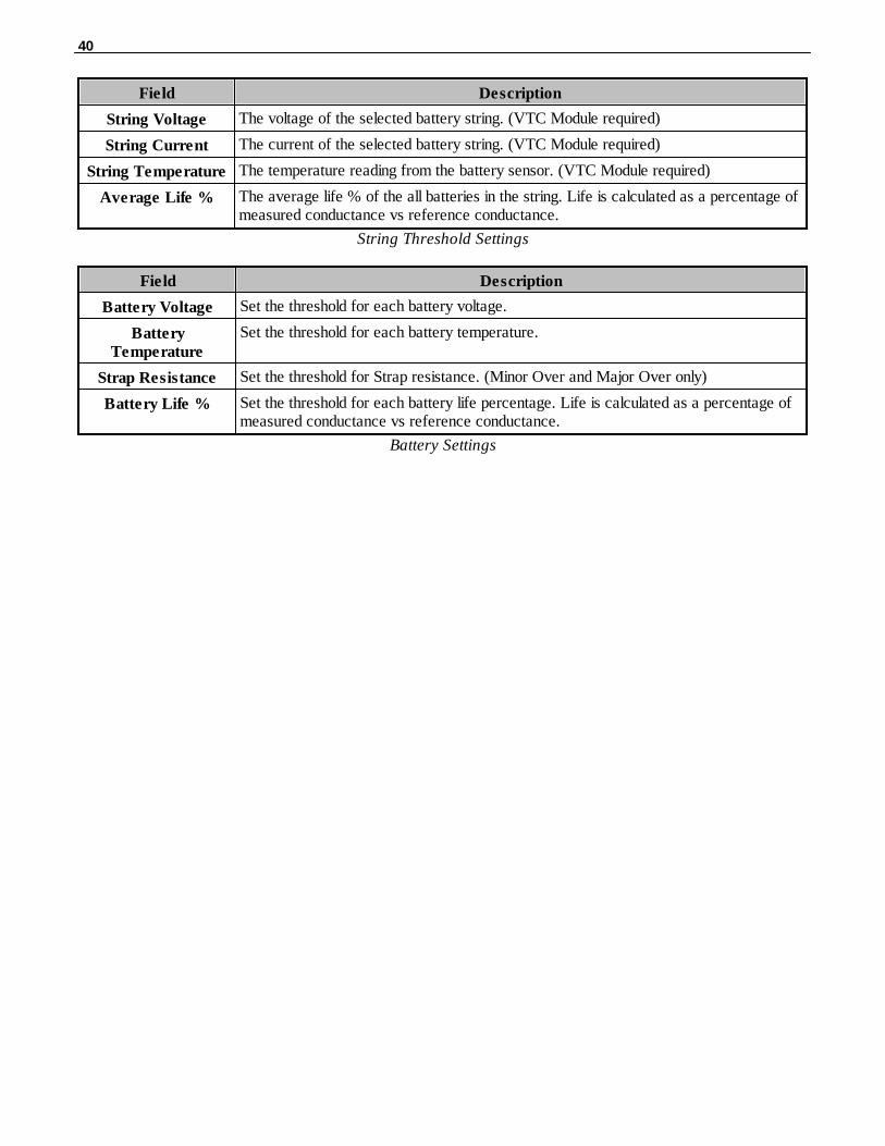
Field Description
String Voltage The voltage of the selected battery string. (VTC Module required)
String Current The current of the selected battery string. (VTC Module required)
String Temperature The temperature reading from the battery sensor. (VTC Module required)
Average Life % The average life % of the all batteries in the string. Life is calculated as a percentage ofmeasured conductance vs reference conductance.
String Threshold Settings
Field Description
Battery Voltage Set the threshold for each battery voltage.
BatteryTemperature
Set the threshold for each battery temperature.
Strap Resistance Set the threshold for Strap resistance. (Minor Over and Major Over only)
Battery Life % Set the threshold for each battery life percentage. Life is calculated as a percentage ofmeasured conductance vs reference conductance.
Battery Settings

41
4.3.17 Setting the System Date and Time
The current date and time can be entered from the Date and Time screen or from an SNMP manager
The date is entered in the mm/dd/yyyy format and the time is entered in the hh:mm:ss format.
! Hot Tip!
The date and time can also be set from an SNMP manager.
Use the following steps to manually set the system's time and date:1. From the Edit menu, select Date and Time, see Figure 2.31.2. Enter the appropriate date, the day of the week, and time.3. Click Submit Data to save the data and time settings.
The date and time will need resetting following a power failure or reboot unless your NetGuardian isequipped with the real-time clock option or network time is enabled.

42
4.3.17.1 Network Time Protocol Support
Configure the Network Time Protocol feature in the Date and Time screen
Network Time Protocol support enables you to set a server to provide your NetGuardian the correct date and time,so you don't have to enter the information if your NetGuardian loses power or has to be reset to factory settings.
To enable Network Time Support:1. From the Edit menu select Date and Time.
2. Click on the Time Zone drop-down menu and select the appropriate time zone.3. Put a check next to Observe DST if you are in an area that observes daylight saving.4. Enter the IP of the network time server in the Time Server IPA field.
Note: To disable NTP support, simply set the Time Server IPA to 255.255.255.255
6. Click Submit Data to save the date and time settings.
4.3.18 PPP Modes
Configure the PPP port settings in the Edit menu > PPP screen
If the LAN connection to your remote sites fails, you can still keep in touch with your remote equipment by using

43
the NetGuardian as a PPP (Point-to-Point Protocol) server via dial-up.
To configure the NetGuardian as a PPP Server:
1. Select PPP from the Edit menu.
2. In the Server section check the Enable Server (also known as Hosting Mode) box.3. Set the IP address that is given to the guest dialing in. (This must be a valid and available IP address for the
subnet on the LAN you will be connecting to, the same one the NetGuardian is connected to.)4. Click Submit Data to save your PPP settings.
Edit the Modem settings for the PPP server in the Edit menu > Ports screen > Modem section
5. Select Ports from the Edit menu.6. Scroll down to the Modem section. Make sure the Ring Count field is greater than 0.7. In Answer Init String field type &Q6.8. Click Submit Data to save your Modem changes.
Select PPP and Telnet access privileges in the Edit menu > Logon > Logon Profiles screen
9. Make sure the users who will need it have the access privilege to access the unit via Telnet. Select Logon inthe Edit menu.

44
! Hot Tip!There can be up to 16 different user names and each one must have its own password.
10. Click the Available link or the user you want to have PPP and Telnet access privileges.11. Under the Access Privileges section check the PPP and Telnet boxes.12. Click Submit Data to save the configuration settings.13. Select Reboot in Edit menu to reboot the NetGuardian. (See section "Rebooting the NetGuardian.")
You also need to configure your remote terminal modem in order to access your NetGuardian by following thesesteps:Windows 98 users: Set baud rate to 9600.
Windows 2000, XP users: In Modem Configuration General tab uncheck Enable modem error control
and Enable compression.Mac OSX users: Use standard dial-in.
4.3.19 Building Access Control
Passwords entered in the NetGuardian will only remain valid until BAC provisioning information is downloadedfrom T/MonXM.
The Building Access Controller (BAC) option is only available for NetGuardian 420 builds with an RS-485connection attached to an Entry Control Unit (ECU).
1. Enter the BAC unit ID number (This is the DCP address of the ECU. It must match the expansion addressbeing polled by the master. Any range from 1-255 is acceptable or enter zero to disable the unit).
2. When Direction is enabled, users are required to enter a 1 for enter immediately following their password or a4 for exit immediately following their password. For example, if the password is 4541600, and direction is enabled,users need to type in 45416001# to enter, or 45416004# to exit.
3. The Defaults column is where door passwords can be edited. These passwords are temporary passwords usedprimarily for turn up and test. A valid password is a combination of up to 14 digits. When a valid password isentered on the keypad, the NetGuardian will send a command to the Entry Control Unit (ECU) to operate the relayto energize the door strike.

45
! Hot Tip!
Be sure to define the data port you are using for the ECU as an ECU type.
To configure Building Access on T/Mon, see your T/MonXM manual.
4.3.20 Configuring IP Cameras
The NetGuardian SiteMon G2 provides users with live streaming video of their remote sites. The direct pan-and-tiltfeatures allows users to visually check the status of their sites from the convenience of their desktop. TheNetGuardian allows your to view up to four cameras from the NetGuardian web interface.
To configure your camera settings: 1. From the Edit menu select Camera.2. Enter the appropriate information in the Name, Description, IP Address, and MAC Address fields for each of
your cameras.Note: See Section "Monitoring Camera Activity" for camera viewing options.
3. Click Submit Data to save your camera configuration settings.
View live streaming video of your remote sites via Web browser
Appropriate Web Browser SettingsIn order to perform the pan-and-tilt functions of the camera, your Web browser must be set to check for newerversions of stored pages at every visit to the page.
The directions for checking for newer versions of stored pages may vary depending on what version ofWindows you are running. The instructions below are relevant to Internet Explorer 5.5 and 6.0 only.
1. With the Web browser open (Internet Explorer version 5.5 or later), click on Tools and select Internet
Options from the drop-down menu.2. Click on the Settings button under the Temporary Internet files heading.3. Click on the Every visit to the page button and click Ok.
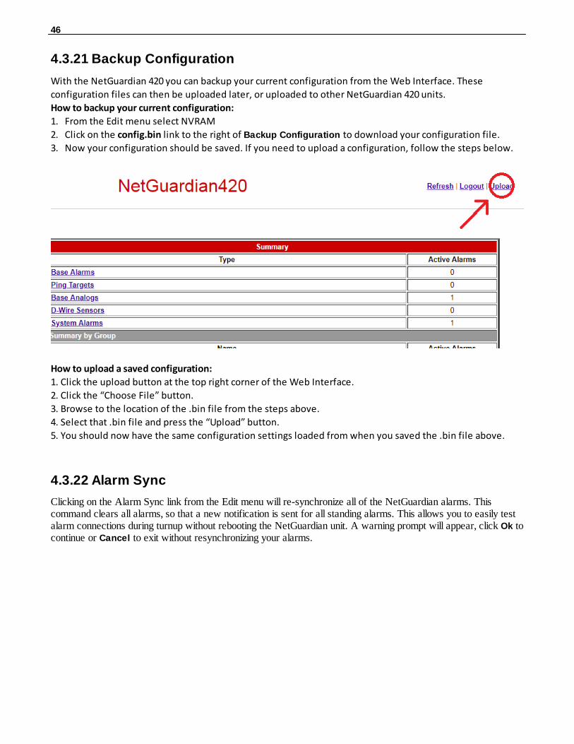
46
4.3.21 Backup Configuration
With the NetGuardian 420 you can backup your current configuration from the Web Interface. These
configuration files can then be uploaded later, or uploaded to other NetGuardian 420 units.
How to backup your current configuration:
1. From the Edit menu select NVRAM
2. Click on the config.bin link to the right of Backup Configuration to download your configuration file.
3. Now your configuration should be saved. If you need to upload a configuration, follow the steps below.
How to upload a saved configuration:
1. Click the upload button at the top right corner of the Web Interface.
2. Click the “Choose File” button.
3. Browse to the location of the .bin file from the steps above.
4. Select that .bin file and press the “Upload” button.
5. You should now have the same configuration settings loaded from when you saved the .bin file above.
4.3.22 Alarm Sync
Clicking on the Alarm Sync link from the Edit menu will re-synchronize all of the NetGuardian alarms. Thiscommand clears all alarms, so that a new notification is sent for all standing alarms. This allows you to easily testalarm connections during turnup without rebooting the NetGuardian unit. A warning prompt will appear, click Ok tocontinue or Cancel to exit without resynchronizing your alarms.
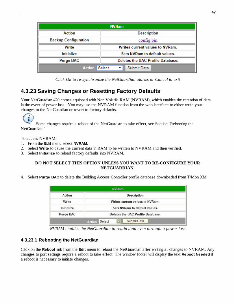
47
Click Ok to re-synchronize the NetGuardian alarms or Cancel to exit
4.3.23 Saving Changes or Resetting Factory Defaults
Your NetGuardian 420 comes equipped with Non Volatile RAM (NVRAM), which enables the retention of datain the event of power loss. You may use the NVRAM function from the web interface to either write yourchanges to the NetGuardian or revert to factory defaults.
Some changes require a reboot of the NetGuardian to take effect, see Section "Rebooting theNetGuardian."
To access NVRAM:1. From the Edit menu select NVRAM.2. Select Write to cause the current data in RAM to be written to NVRAM and then verified. 3. Select Initialize to reload factory defaults into NVRAM.
DO NOT SELECT THIS OPTION UNLESS YOU WANT TO RE-CONFIGURE YOURNETGUARDIAN.
4. Select Purge BAC to delete the Building Access Controller profile database downloaded from T/Mon XM.
NVRAM enables the NetGuardian to retain data even through a power loss
4.3.23.1 Rebooting the NetGuardian
Click on the Reboot link from the Edit menu to reboot the NetGuardian after writing all changes to NVRAM. Anychanges to port settings require a reboot to take effect. The window footer will display the text Reboot Needed ifa reboot is necessary to initiate changes.

48
Monitor Mode4.4
From Monitor Mode, you can monitor all of the unit's alarms, analogs, ping targets, cameras, and issue controls. When you logon to the NetGuardian, it will be in Monitor Mode. To revert to Monitor Mode from Edit Mode,simply click the blue Monitor button.
If your hardware supports xFLSH, periodically a gray line will flash near the top of the interface. This indicatesthat data is being refreshed for the interface.
If your hardware supports xFLSH and if there is a problem with the connection or a problem with the data loading,an error message will be displayed.
NOTE: When SSL (secure) mode is enabled, the web refresh will be no faster than 30 seconds (forexample, if your refresh time is configured for 5 seconds, web refreshes will revert to a 30 secondrefresh time).

49
4.4.1 Alarm Summary
Entering Monitor Mode will bring you to the Alarm Summary Screen. From here, you can see the total number ofactive alarms, ping targets, analogs, and system alarms. You can also view alarms by point group. Click any ofthe links in the Alarm Summary to see details or use the navigation links on the left to browse your NetGuardian'salarms and resources.
4.4.2 Base Alarms
From the Base Alarms screen, you can view the state of your NetGuardian's 20 base alarms.
If you added alarms to point groups, the state field will display the appropriate set or clear messages. If you'reever unsure of the set or clear messages, green font will always indicate a cleared alarm, red will always indicatea set alarm.
4.4.3 Ping Targets
You can monitor your NetGuardian's 32 ping targets from the Monitor > Ping Targets screen.
If you added your ping targets to point groups, the state field will display the appropriate set or clear messages. Ifyou're ever unsure of the set or clear messages, green font will always indicate a cleared alarm, red will alwaysindicate a set alarm.

50
4.4.4 Base Analogs
The Monitor menu > Analogs screen provides a table or a gauge display (depending on your configuration in EditMode) of each analog channel, the current reading, the units being read, and alarm conditions (major under, minorunder, major over, minor over) according to your analog settings.
Table View Gauge View
If you selected "None" for the analog guage type in edit mode (see section 13.3.12), the interface will display theanalog value as shown below.
Note : With the D-Wire top board build option, D-Wire Sensors 1-8 and 9-16 links will appear under the Analogslink. These pages add the ROMID columns to the original analog tables. If a sensor is not detected, its ROMIDfont will appear red.

51
4.4.5 System Alarms
The System Alarms link will show you the state of your NetGuardian's internal alarms.
If you added alarms to point groups, the state field will display the appropriate set or clear messages. However, inthe state field, green font will always indicate a cleared alarm, red will always indicate a set alarm.
4.4.6 Accum Timer
Clicking on Accum. Timer will take you to the Accumulation Timer. From here, you can see how many times analarm (configured from the Accum Timer field in Edit Mode) has occurred in a set period of time.
4.4.7 Controls
Selecting Controls from the Monitor Mode navigation menu gives the user access to the unit's control relays
To operate controls:1. Under the State field, choose a command (Opr - operate, Rls - release, or Mom - momentary). 2. Click Submit Data to issue the control.
The control relay's normal state - open or closed - is determined by a PCB jumper. Operating a control thuschanges the normal state of the relay (energizes it) until it is released (de-energized). By default, the momentary

52
command energizes the relay for approximately one second before it is released again. Use the event qualifiers toextend the momentary period.
4.4.8 Event Log
To view a log of alarm events, click Event Log in the Monitor Menu Navigation frame.
The NetGuardian's Event Log allows the NetGuardian to post and monitor up to 100 events including power up,base and system alarms, ping alarms, analog alarms, and controls. Posted events for the various alarms includeboth alarm and clear status. All information in the event log will be erased upon reboot or a power failure.
Event Log Field Description
Event Event number (1-500)
Date Date the event occurred
Time Time the event occurred
Group Group number of the point
State State of the event (A=alarm, C=clear)
Disp DCP display
Point Point reference.
DescriptionUser defined description of the event as entered in the alarm point and relaydescription fields
Event Logging window field descriptions
4.4.9 Monitoring Port Activity
To view the data being received by the connected equipment, select the data port number from the Monitormenu > Port Receive drop-down menu
The Port Transmit and Port Receive screens provide live status information for the NetGuardian's 4 data ports by
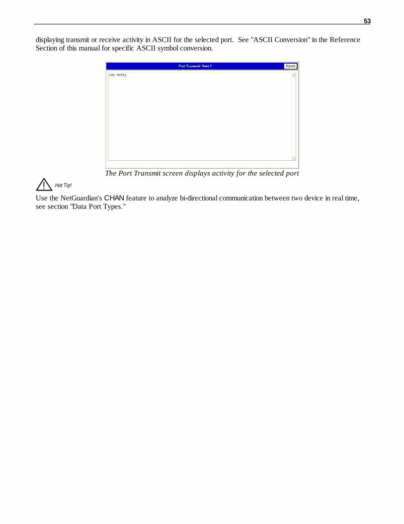
53
displaying transmit or receive activity in ASCII for the selected port. See "ASCII Conversion" in the ReferenceSection of this manual for specific ASCII symbol conversion.
The Port Transmit screen displays activity for the selected port
! Hot Tip!
Use the NetGuardian's CHAN feature to analyze bi-directional communication between two device in real time,see section "Data Port Types."
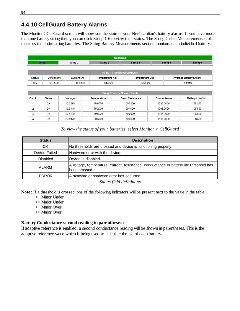
54
4.4.10 CellGuard Battery Alarms
The Monitor->CellGuard screen will show you the state of your NetGuardian's battery alarms. If you have morethan one battery string then you can click String 1-6 to view their status. The String Global Measurements tablemonitors the entire string batteries. The String Battery Measurements section monitors each individual battery.
To view the status of your batteries, select Monitor > CellGuard
Status Description
OK No thresholds are crossed and device is functioning properly.
Device Failed Hardware error with the device.
Disabled Device is disabled.
ALARMA voltage, temperature, current, resistance, conductance or battery life threshold hasbeen crossed.
ERROR A software or hardware error has occurred.
Status field definitions
Note: If a threshold is crossed, one of the following indicators will be present next to the value in the table.< Minor Under<< Major Under> Minor Over>> Major Over
Battery Conductance second reading in parentheses:If adaptive reference is enabled, a second conductance reading will be shown in parentheses. This is theadaptive reference value which is being used to calculate the life of each battery.

55
Firmware Upgrade4.5
To upgrade your NetGuardian 420 firmware, click on the upload link at the top right corner of the Web
Interface.
At the Multiload screen, click the “Choose File” button, browse to the firmware file that you’ve downloaded
from www.dpstele.com and click Upload. The page will display “Upload Successful” When the upload is
complete. Click on the “Site main page” link to return to the Monitor Summary page.
Browse for downloaded firmware upgrade
Frequently Asked Questions5
Here are answers to some common questions from NetGuardian users. The latest FAQs can be found on theNetGuardian support web page, http://www.dpstelecom.com.
If you have a question about the NetGuardian, please call us at (559) 454-1600 or e-mail us at

56
General FAQs5.1
Q. How do I telnet to the NetGuardian?A. You must use Port 2002 to connect to the NetGuardian. Configure your Telnet client to connect using TCP/
IP (not "Telnet," or any other port options). For connection information, enter the IP address of theNetGuardian and Port 2002. For example, to connect to the NetGuardian using the standard Windows Telnetclient, click Start, click Run, and type "telnet <NetGuardian IP address> 2002."
Q. How do I connect my NetGuardian to the LAN?A. To connect your NetGuardian to your LAN, you need to configure the unit IP address, the subnet mask and
the default gateway. A sample configuration could look like this:Unit Address: 192.168.1.100subnet mask: 255.255.255.0Default Gateway: 192.168.1.1Save your changes by writing to NVRAM and reboot. Any change to the NetGuardian's IP configurationrequires a reboot.
Q. When I connect to the NetGuardian through the craft port on the front panel it either doesn't workright or it doesn't work at all. What's going on?
A. Make sure your using the right COM port settings. Your COM port settings should read:Bits per second: 9600 (9600 baud)Data bits: 8Parity: NoneStop bits: 1Flow control: NoneImportant! Flow control must be set to none . Flow control normally defaults to hardware in most terminalprograms, and this will not work correctly with the NetGuardian.
Q. I can't change the craft port baud rate.A. If you select a higher baud rate, you must set your terminal emulator program to the new baud rate, press
Enter, and type in your password. If your terminal emulator is set to a slower baud rate than the craft port,normal keys can appear as a break key — and the craft port interprets a break key as an override that resetsthe baud rate to the standard 9600 baud.
Q. How do I use the NetGuardian to access TTY interfaces on remote site equipment?A. If your remote site device supports RS-232, you can connect it to one of the eight data ports located on the
NetGuardian back panel. To make the data port accessible via LAN, configure the port for TCP/IP operation.You now have a LAN-based proxy port connection that lets you access your device's TTY interface througha Telnet session.
Q. I just changed the port settings for one of my data ports, but the changes did not seem to takeeffect even after I wrote the NVRAM.
A. In order for data port and craft port changes (including changes to the baud rate and word format) to takeeffect, the NetGuardian must be rebooted. Whenever you make changes, remember to write them to theNetGuardian's NVRAM so they will be saved when the unit is rebooted.
Q. The LAN link LED is green on my NetGuardian, but I can't poll it from my T/Mon.A. Some routers will not forward packets to an IP address until the MAC address of the destination device has
been registered on the router's Address Resolution Protocol (ARP) table. Enter the IP address of yourgateway and your T/Mon system to the ARP table.

57
Q. What do the terms "port," "address," "display" and "alarm point" mean?A. These terms refer to numbers that designate the location of a network alarm, from the most general (a port to
which several devices are connected) to the most specific (an individual alarm sensor).Port: A number designating a serial port through which a monitoring device collects data.Address: A number designating a device connected to a port.Display: A number designating a logical group of 64 alarm points.Alarm Point: A number designating a contact closure that is activated when an alarm condition occurs. Forexample, an alarm point might represent a low oil sensor in a generator or an open/close sensor in a door.These terms originally referred only to physical things: actual ports, devices, and contact closures. For the sakeof consistency, port-address-display-alarm point terminology has been extended to include purely logicalelements: for example, the NetGuardian reports internal alarms on Port 99, Address 1.
Q. What characteristics of an alarm point can be configured through software? For instance, can point4 be used to sense an active-low signal, or point 5 to sense a level or a edge?
A. The NetGuardian's standard configuration is for all alarm points to be level-sensed. You cannot useconfiguration software to convert alarm points to TTL (edge-sensed) operation. TTL alarm points are ahardware option that must be specified when you order your NetGuardian. Ordering TTL points for yourNetGuardian does not add to the cost of the unit What you can do with the configuration software is changeany alarm point from "Normal" to "Reversed" operation. Switching to Reversed operation has different effects,depending on the kind of input connected to the alarm point:
· If the alarm input generates an active-high signal, switching to Reversed operation means theNetGuardian will declare an alarm in the absence of the active-high signal, creating the practical equivalent ofan active-low alarm.
· If the alarm input generates an active-low signal, switching to Reversed operation means theNetGuardian will declare an alarm in the absence of the active-low signal, creating the practical equivalent ofan active-high alarm.
· If the alarm input is normally open, switching to Reversed operation converts it to a normally closedalarm point.
· If the alarm input is normally closed, switching to Reversed operation converts it to a normally openalarm point.
Q. Every time my NetGuardian starts up, I have to reenter the date and time. How can I get theNetGuardian to automatically maintain the date and time setting?
A. You have three options for keeping the correct time on your NetGuardian:Real Time Clock Option: You can order your NetGuardian with the Real Time Clock hardware option.Once it's set, the Real Time Clock will keep the correct date and time, regardless of reboots.Network Time Protocol Synchronization: If your NetGuardian has Firmware Version 2.9F or later, youcan configure the unit to automatically synchronize to a Network Time Protocol (NTP) server.
· To get the latest NetGuardian firmware, sign in to MyDPS at www.dpstelecom.com/mydps.
· For instructions on configuring your NetGuardian to use NTP synchronization, see the "Network TimeProtocol Support" section of this manual.T/Mon RTU Time Sync Signal: You can configure your T/Mon NOC to send an RTU Time Sync signal ata regular interval, which you can set to any time period between 10 and 10,080 minutes. The Time Sync willautomatically synchronize the NetGuardian's clock to the T/Mon's clock. And if you set your T/Mon to NTPsynchronization, you'll make sure you have consistent, accurate time stamps throughout your monitoringnetwork.
Q. How do I back up my NetGuardian configuration?A. Use FTP
You can use File Transfer Protocol (FTP) to read and write configuration files to the NetGuardian's NVRAM,but you can't use FTP to edit configuration files.

58
SNMP FAQs5.2
Q. How do I configure the NetGuardian to send traps to an SNMP manager? Is there a separate MIBfor the NetGuardian? How many SNMP managers can the agent send traps to? And how do I setthe IP address of the SNMP manager and the community string to be used when sending traps?
A. The NetGuardian begins sending traps as soon as the SNMP managers are defined. The NetGuardian MIB isincluded on the NetGuardian Resource CD. The MIB should be compiled on your SNMP manager. (Note:MIB versions may change in the future.) The unit supports 2 SNMP managers, which are configured byentering its IP address in the Trap Address field of Ethernet Port Setup. You can also configure up to eightsecondary SNMP managers, which is configured by selecting the secondary SNMP managers as pagerrecipients. Community strings are configured globally for all SNMP managers. To configure the communitystrings, choose System from the Edit menu, and enter appropriate values in the Get, Set, and Trap fields.
Q. Does the NetGuardian support MIB-2 and/or any other standard MIBs?A. The NetGuardian supports the bulk of MIB-2.
Q. Does the NetGuardian SNMP agent support both NetGuardian and T/MonXM variables?A. The NetGuardian SNMP agent manages an embedded MIB that supports only the NetGuardian's RTU
variables. The T/MonXM variables are included in the distributed MIB only to provide SNMP managers witha single MIB for all DPS Telecom products.
Q. How many traps are triggered when a single point is set or cleared? The MIB defines traps like"major alarm set/cleared," "RTU point set," and a lot of granular traps, which could imply thatmore than one trap is sent when a change of state occurs on one point.
A. Generally, a single change of state generates a single trap, but there are two exception to this rule. Exception1: the first alarm in an "all clear" condition generates an additional "summary point set" trap. Exception 2: thefinal clear alarm that triggers an "all clear" condition generates an additional "summary point clear" trap.
Q. What does "point map" mean?A. A point map is a single MIB leaf that presents the current status of a 64-alarm-point display in an ASCII-
readable form, where a "." represents a clear and an "x" represents an alarm.
Q. The NetGuardian manual talks about eight control relay outputs. How do I control these from mySNMP manager?
A. The control relays are operated by issuing the appropriate set commands, which are contained in the DPScontrol grid. For more information about the set commands, see Appendix, "Display Mapping," in any of theNetGuardian software configuration guides.
Q. How can I associate descriptive information with a point for the RTU granular traps?A. The NetGuardian alarm point descriptions are individually defined using the Web Browser or TTY interfaces.
Q. My SNMP traps aren't getting through. What should I try?A. Try these three steps:
1. Make sure that the Trap Address (IP address of the SNMP manager) is defined. (If you changed theTrap Address, make sure you saved the change to NVRAM and rebooted.)
2. Make sure all alarm points are configured to send SNMP traps.3. Make sure the NetGuardian and the SNMP manager are both on the network. Use the NetGuardian's
ping command to ping the SNMP manager.

59
Pager FAQs5.3
Q. Why won't my alpha pager work?A. To configure the NetGuardian to send alarm notifications to an alpha pager, enter the data phone number for
your pager in the Phone Number field. This phone number should connect to your pager service's modem.Then enter the PIN for your pager in the PIN/Rcpt/Port field. You don't need to enter anything in any of theother fields. If you still don't receive pages, try setting the Dial Modem Init string to ATS37=9. This will limitthe NetGuardian's connection speed. Be sure to use the rpt debug feature, if needed.
Q. Numeric pages don't come in or are cut off in the middle of the message. What's wrong?A. You need to set a delay between the time the NetGuardian dials your pager number and the time the
NetGuardian begins sending the page message. You can set the delay in the Pager Number field, where youenter your pager number. First enter the pager number, then enter some commas directly after the number.Each comma represents a two-second delay. So, for example, if you wanted an eight-second delay, you wouldenter "555-1212,,,," in the Pager Number field.
Q. What do I need to do to set up e-mail notifications?A. You need to assign the NetGuardian an e-mail address and list the addresses of e-mail recipients. Let's explain
some terminology. An e-mail address consists of two parts, the user name (everything before the "@" sign)and the domain (everything after the "@" sign). To assign the NetGuardian an e-mail address, choose Systemfrom the Edit menu. Enter the NetGuardian's user name in the Name field (it can't include any spaces) and thedomain in the Location field. For example, if the system configuration reads:
Name: netguardianLocation: proactive.com
Then e-mail notifications from the NetGuardian will be sent from the address "[email protected]."The next step is to list the e-mail recipients. Choose Pagers from the Edit menu. For each e-mail recipient,enter his or her e-mail domain in the Phone/Domain field and his or her user name in the PIN/Rcpt/Port field.You must also enter the IP address of an SMTP server in the IPA field and configure the alarm point to usethe pager you setup as email.

60
Technical Support6
DPS Telecom products are backed by our courteous, friendly Technical Support representatives, who will give youthe best in fast and accurate customer service. To help us help you better, please take the following steps beforecalling Technical Support:
1. Check the DPS Telecom website.You will find answers to many common questions on the DPS Telecom website, at http://www.dpstelecom.com/support/. Look here first for a fast solution to your problem.
2. Prepare relevant information.
Having important information about your DPS Telecom product in hand when you call will greatly reduce thetime it takes to answer your questions. If you do not have all of the information when you call, our TechnicalSupport representatives can assist you in gathering it. Please write the information down for easy access. Pleasehave your user manual and hardware serial number ready.
3. Have access to troubled equipment.Please be at or near your equipment when you call DPS Telecom Technical Support. This will help us solve yourproblem more efficiently.
4. Call during Customer Support hours.Customer support hours are Monday through Friday, from 7 A.M. to 6 P.M., Pacific time. The DPS TelecomTechnical Support phone number is (559) 454-1600.
Emergency Assistance: Emergency assistance is available 24 hours a day, 7 days a week. For emergencyassistance after hours, allow the phone to ring until it is answered with a paging message. You will beasked to enter your phone number. An on-call technical support representative will return your call assoon as possible.

61
End User License Agreement7
All Software and firmware used in, for, or in connection with the Product, parts, subsystems, or derivatives thereof, inwhatever form, including, without limitation, source code, object code and microcode, including any computerprograms and any documentation relating to or describing such Software is furnished to the End User only under anon-exclusive perpetual license solely for End User's use with the Product.
The Software may not be copied or modified, in whole or in part, for any purpose whatsoever. The Software may notbe reverse engineered, compiled, or disassembled. No title to or ownership of the Software or any of its parts istransferred to the End User. Title to all patents, copyrights, trade secrets, and any other applicable rights shallremain with the DPS Telecom.
DPS Telecom's warranty and limitation on its liability for the Software is as described in the warranty informationprovided to End User in the Product Manual.
End User shall indemnify DPS Telecom and hold it harmless for and against any and all claims, damages, losses,costs, expenses, obligations, liabilities, fees and costs and all amounts paid in settlement of any claim, action orsuit which may be asserted against DPS Telecom which arise out of or are related to the non-fulfillment of anycovenant or obligation of End User in connection with this Agreement.
This Agreement shall be construed and enforced in accordance with the laws of the State of California, withoutregard to choice of law principles and excluding the provisions of the UN Convention on Contracts for theInternational Sale of Goods. Any dispute arising out of the Agreement shall be commenced and maintained only inFresno County, California. In the event suit is brought or an attorney is retained by any party to this Agreement toseek interpretation or construction of any term or provision of this Agreement, to enforce the terms of thisAgreement, to collect any money due, or to obtain any money damages or equitable relief for breach, the prevailingparty shall be entitled to recover, in addition to any other available remedy, reimbursement for reasonable attorneys'fees, court costs, costs of investigation, and other related expenses.

62

63

“Your Part ners in Network Alarm Management ”
“Dependable, Powerful Solutionsthat allow users to monitor larger,more complicated networks with a
smaller, less trained staff”
www.dpstelecom.com4955 E Yale • Fresno, CA 93727
559-454-1600 • 800-622-3314 • 559-454-1688 fax