neo wall switch 505xnl a, e505xnl e -...
TRANSCRIPT
Installation Instructions
Neo Wall Switch
505xNL A, E505xNL E Series

505xNL A Series, E505xNL E Series C-Bus Neo Wall Switch Installation Instructions
© Clipsal Australia Pty Ltd
Contents
1.0 Product Range ................................................................................................3
2.0 Important Notes ..............................................................................................3
3.0 Description ......................................................................................................3
4.0 Installation Considerations ...........................................................................4
4.1 Location .....................................................................................................4
4.2 Multiple Neo Wall Switches ........................................................................4
5.0 Mounting Instructions ....................................................................................5
6.0 C-Bus Network Connection ...........................................................................6
7.0 C-Bus Power Requirements ...........................................................................7
8.0 Megger Testing ................................................................................................7
9.0 Programming Requirements .........................................................................7
10.0 Electrical Specifications ................................................................................8
11.0 Mechanical Specifications .............................................................................8
11.1 Neo ‘A’ Series ..........................................................................................9
11.2 Neo ‘E’ Series ..........................................................................................9
12.0 Standards Complied .....................................................................................10
13.0 Warranty ........................................................................................................11
14.0 Technical Support and Troubleshooting.....................................................12
3 of 12© Clipsal Australia Pty Ltd
505xNL A Series, E505xNL E Series C-Bus Neo Wall Switch Installation Instructions
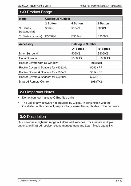
1.0 Product Range
Model Catalogue Number
2 Button 4 Button 8 Button
‘A’ Series (rectangular)
5052NL 5054NL 5058NL
‘E’ Series (square) E5052NL E5054NL E5058NL
Accessory Catalogue Number
‘A’ Series ‘E’ Series
Inner Surround 5050IS E5050IS
Outer Surround 5050OS E5050OS
Rocker Covers with ID Window 5052NRI
Rocker Covers & Spacers for x5052NL 5052NRP
Rocker Covers & Spacers for x5054NL 5054NRP
Rocker Covers & Spacers for x5058NL 5058NRP
Infrared Remote Control 5038TX2
2.0 Important NotesDo not connect mains to C-Bus Neo units.•
The use of any software not provided by Clipsal, in conjunction with the •installation of this product, may void any warranties applicable to the hardware.
3.0 DescriptionC-Bus Neo is a high-end range of C-Bus wall switches. Units feature multiple buttons, an infrared receiver, scene management and Learn Mode capability.
4 of 12
505xNL A Series, E505xNL E Series C-Bus Neo Wall Switch Installation Instructions
© Clipsal Australia Pty Ltd
4.0 Installation Considerations
4.1 Location
It is important to select the right location to install a C-Bus Neo wall switch. Some considerations include:
Provide easy access to the unit for switching lights and selecting scenes.•
Do not obstruct the infrared receiving window.•
Choose a location free of water, excess humidity, direct sunlight and heavy dust.•
Allow adequate ventilation.•
Do not cover the unit.•
C-Bus Neo wall switches are designed for indoor use only.•
Units may be mounted vertically or horizontally.•
4.2 Multiple Neo Wall Switches
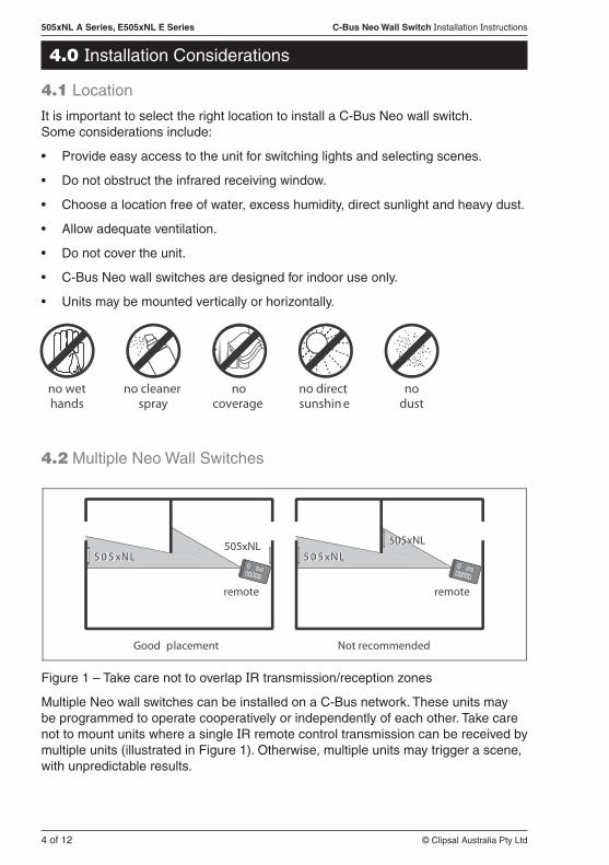
Figure 1 – Take care not to overlap IR transmission/reception zones
Multiple Neo wall switches can be installed on a C-Bus network. These units may be programmed to operate cooperatively or independently of each other. Take care not to mount units where a single IR remote control transmission can be received by multiple units (illustrated in Figure 1). Otherwise, multiple units may trigger a scene, with unpredictable results.
no wethands
no cleanerspray
nocoverage
no directsunshin e
nodust
Not recommended
remote
Good placement
remote
505xNLLNx505LNx505
505xNL

5 of 12© Clipsal Australia Pty Ltd
505xNL A Series, E505xNL E Series C-Bus Neo Wall Switch Installation Instructions
5.0 Mounting InstructionsThere are several options for mounting a C-Bus Neo wall switch. You can:
use a wall box (in solid or stud walls)•
use a c-clip or mounting flange (in stud/plasterboard walls)•
screw directly into wall plugs.•
‘A’ Series C-Bus Neo units suit standard 84mm centre mounting accessories, such as the Clipsal 155, 155VH and 157/1. Mounting using a c-clip is shown in Figure 2.
‘E’ Series C-Bus Neo units suit standard 60.3mm centre mounting accessories, such as the Clipsal E157 and E5050MF. Mounting using an E157 Series wall box is shown in Figure 3.
Figure 3 – Mounting an ‘E’ Series Neo using an E157 wall box
Figure 2 – Mounting an ‘A’ Series Neo using a c-clip
6 of 12
505xNL A Series, E505xNL E Series C-Bus Neo Wall Switch Installation Instructions
© Clipsal Australia Pty Ltd
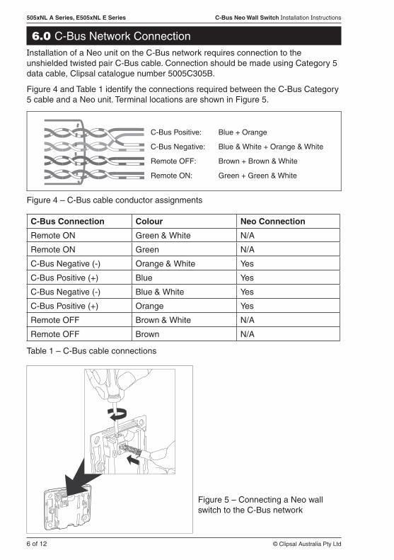
6.0 C-Bus Network ConnectionInstallation of a Neo unit on the C-Bus network requires connection to the unshielded twisted pair C-Bus cable. Connection should be made using Category 5 data cable, Clipsal catalogue number 5005C305B.
Figure 4 and Table 1 identify the connections required between the C-Bus Category 5 cable and a Neo unit. Terminal locations are shown in Figure 5.
C-Bus Connection Colour Neo Connection
Remote ON Green & White N/A
Remote ON Green N/A
C-Bus Negative (-) Orange & White Yes
C-Bus Positive (+) Blue Yes
C-Bus Negative (-) Blue & White Yes
C-Bus Positive (+) Orange Yes
Remote OFF Brown & White N/A
Remote OFF Brown N/A
Table 1 – C-Bus cable connections
Figure 5 – Connecting a Neo wall switch to the C-Bus network
Figure 4 – C-Bus cable conductor assignments
C-Bus Positive: Blue + Orange
C-Bus Negative: Blue & White + Orange & White
Remote OFF: Brown + Brown & White
Remote ON: Green + Green & White

7 of 12© Clipsal Australia Pty Ltd
505xNL A Series, E505xNL E Series C-Bus Neo Wall Switch Installation Instructions
7.0 C-Bus Power RequirementsA C-Bus Neo unit draws 22mA from the C-Bus network. Adequate C-Bus power supply units must be installed to support the connected devices.
The Network window of a C-Bus Toolkit project provides a summary of a C-Bus network, according to the units added to the database. This can be helpful in determining the power supply requirements of a particular network.
8.0 Megger TestingImportant points when megger testing an electrical installation:
Only megger test when mains cabling is disconnected from C-Bus output units.•
Do not megger test the C-Bus cable.•
9.0 Programming RequirementsC-Bus Neo wall switches are learn enabled devices. This means you can create relationships between input and output units without a computer (using Learn Mode).
Learn Mode allows you to link multiple units into a common network. You can assign a load (such as a light on a dimmer unit), with a controller (such as a Neo wall switch) by touching the two units, one after the other. Refer to the “Quick Start Guide to Programming: C-Bus2 Learn Units” booklet for more information.
In a sophisticated installation, some of the basic settings created by Learn Mode may need to be overridden to create a particular effect. The latest C-Bus Toolkit software may be downloaded from the Clipsal website (www.clipsal.com/cis).

8 of 12
505xNL A Series, E505xNL E Series C-Bus Neo Wall Switch Installation Instructions
© Clipsal Australia Pty Ltd
10.0 Electrical Specifications
Parameter Description
C-Bus supply voltage 15 to 36V d.c. 22mA for normal operation, (does not provide current to the C-Bus network).
C-Bus a.c. input impedance 100kΩ @ 1kHz
Electrical isolation 3.75kV RMS from C-Bus to mains (provided externally to x505xNL Series unit)
Maximum number of units per network 100
Control functions Load switching, dimming, timers, scene control
Status indicators User configurable orange, blue; with blue night light
Warm-up time 5 seconds
C-Bus connection One terminal block to accommodate 0.2 to 1.3mm2 (24 to 16 AWG)
Operating temperature range 0 to 45 °C
Operating humidity range 10 to 95% RH
11.0 Mechanical Specifications
Parameter ‘A’ Series ‘E’ Series
Dimensions (W×H×D) 76 × 116 × 22mm 87 × 87 × 22mm
Protrusion from wall 8mm 8mm
Mounting centres 84mm 60.3mm
Weight 77g 67g

9 of 12© Clipsal Australia Pty Ltd
505xNL A Series, E505xNL E Series C-Bus Neo Wall Switch Installation Instructions
11.1 Neo ‘A’ Series
11.2 Neo ‘E’ Series
116mm
76mm
68mm
22mm
51mm
87mm
87mm
51mm
68mm
22mm

10 of 12
505xNL A Series, E505xNL E Series C-Bus Neo Wall Switch Installation Instructions
© Clipsal Australia Pty Ltd
12.0 Standards Complied
Declarations of Conformity
Australian/New Zealand EMC & Electrical Safety Frameworks & Standards
C-Bus Neo 505xNL and E505xNL Series products comply with the following:
Regulation Standard Title
EMC (C-Tick) AS/NZS1044, CISPR 14 RFI Emissions
European Directives and Standards
C-Bus Neo 505xNL and E505xNL Series products comply with the following:
European Council Directive
Standard Title
EMC Directive 89/336/EEC
EN55014-1 Electrical Motor-operated and Thermal Appliances
EN60669-2-1 Switches for Household and Similar Fixed Electrical Installations Part 2-1
EN61000-3-2 Limits for Harmonic Current Emissions
EN61000-3-3 Limitation of Voltage Changes, Fluctuations and Flicker
EN61000-4-2 Immunity to ESD
EN61000-4-3 Immunity to RF EM Fields
EN61000-4-4 Immunity to EFT
EN61000-4-5 Immunity to Surge Voltages
EN61000-4-6 Continuous RF Immunity
Other International Directives and Standards
C-Bus Neo 505xNL and E505xNL Series products comply with the following:
Regulation IEC Standard Title
EMC 61000-3-2 Limits for Harmonic Current Emissions
61000-3-3 Voltage Fluctuations and Flicker Standard
61000-4-2 Immunity to ESD
61000-4-3 Immunity to RF EM Fields
61000-4-4 Immunity to EFT
61000-4-5 Immunity to Surge Voltages
11 of 12© Clipsal Australia Pty Ltd
505xNL A Series, E505xNL E Series C-Bus Neo Wall Switch Installation Instructions
13.0 WarrantyC-Bus Neo 505xNL and E505xNL Series wall switches carry a two (2) year warranty against manufacturing defects.
Warranty Statement
The benefits conferred herein are in addition to, and in no way shall be deemed to derogate; either expressly or by implication, any or all other rights and remedies in respect to the Clipsal product, which the consumer has under the Commonwealth Trade Practices Act or any other similar State or Territory Laws.
The warrantor is Clipsal Australia Pty Ltd of 33-37 Port Wakefield Rd, Gepps Cross, South Australia, 5094. Telephone (08) 8161 0511. With registered offices in all Australian States.
This Clipsal product is guaranteed against faulty workmanship and materials for a period of two (2) years from the date of installation.
Clipsal Australia Pty Ltd reserves the right, at its discretion, to either repair free of parts and labour charges, replace or offer refund in respect to any article found to be faulty due to materials, parts or workmanship.
This warranty is expressly subject to the Clipsal product being installed, wired, tested, operated and used in accordance with the manufacturer’s instructions.
All costs of a claim shall be met by Clipsal Australia Pty Ltd, however should the product that is the subject of the claim be found to be in good working order, all such costs shall be met by the claimant.
When making a claim, the consumer shall forward the Clipsal product to the nearest office of Clipsal Australia Pty Ltd with adequate particulars of the defect within 28 days of the fault occurring. The product should be returned securely packed, complete with details of the date and place of purchase, description of load, and circumstances of malfunction.
For all warranty enquiries, contact your local Clipsal Sales Representative. The address and contact number of your nearest Clipsal Australia office can be found at http://www.clipsal.com/locations or by telephoning Technical Support (refer to the back page).

F1869/02 CLIPCOM 21361 July 2010
Clipsal Australia Pty Ltd reserves the right to change specifications, modify designs and discontinue items without incurring obligation and whilst every effort is made to ensure that descriptions, specifications and other information in this catalogue are correct, no warranty is given in respect thereof and the company shall not be liable for any error therein.
© Clipsal Australia Pty Ltd. The identified trademarks and copyrights are the property of Clipsal Australia Pty Ltd unless otherwise noted.
Clipsal Australia Pty LtdA member of Schneider Electric
Contact us: [email protected]
National Customer Care Enquiries:
Tel 1300 2025 25 Fax 1300 2025 56
clipsal.com
14.0 Technical Support and TroubleshootingFor further assistance in using this product, consult your nearest Clipsal Integrated Systems (CIS) Sales Representative or Technical Support Officer.
Technical Support Contact Numbers
Australia 1300 722 247 (CIS Technical Support Hotline)
New Zealand 0800 888 219 (CIS Technical Support Hotline)
Northern Asia +852 2484 4157 (Clipsal Hong Kong)
South Africa 011 314 5200 (Technical Support)
Southern Asia +603 7665 3555 Ext. 236 or 242 (CIS Malaysia)
United Kingdom 0870 608 8 608 (Schneider Electric Support)
Technical Support Email: [email protected]