needle roller and cage assemblies for crank pins and piston pins
TRANSCRIPT

Needle roller and cage assembliesfor crank pins and piston pins

Schaeffler Technologies TPI 94 1
Product overview Needle roller and cage assembliesfor crank pins and piston pins ................................................... 2
Features Needle roller and cage assemblies for crank pins ...................... 3
Needle roller and cage assemblies for piston pins..................... 3
Design andsafety guidelines
Guidance of the connecting rod................................................. 4
Design of adjacent parts............................................................ 5
Preferred enveloping circle diameterof needle roller and cage assemblies......................................... 5
Accuracy ................................................................................................. 6
Radial internal clearance ........................................................... 7
Sort plan for crank pin bearing arrangements ............................ 8
Sort plan for piston pin bearing arrangements........................... 8
Special designs ................................................................................................. 9
Ordering example andordering designation
................................................................................................. 9
Dimension tables Needle roller and cage assemblies for crank pins ...................... 10
Needle roller and cage assemblies for piston pins..................... 11
Appendix Calculation of rolling bearings in crank machines...................... 12
Datasheets, functional diagram................................................. 12
Datasheet · Needle roller and cage assembliesfor crank pins and piston pins ................................................... 13
Datasheet · Functional diagram and examples of load cases ..... 15
Needle roller and cage assembliesfor crank pins and piston pins
2 TPI 94 Schaeffler Technologies
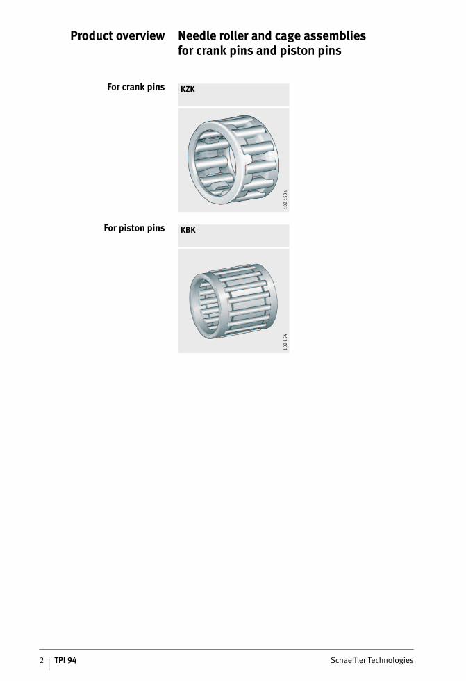
For crank pins KZK
102
153a
For piston pins KBK
102
154
Product overview Needle roller and cage assembliesfor crank pins and piston pins
Schaeffler Technologies TPI 94 3
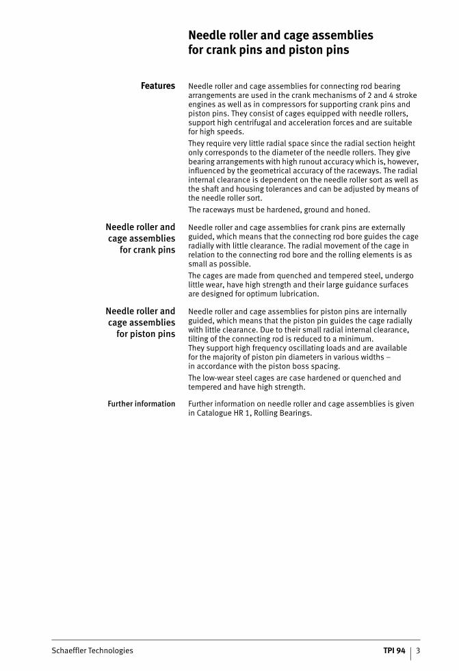
Features Needle roller and cage assemblies for connecting rod bearing arrangements are used in the crank mechanisms of 2 and 4 stroke engines as well as in compressors for supporting crank pins and piston pins. They consist of cages equipped with needle rollers, support high centrifugal and acceleration forces and are suitablefor high speeds.
They require very little radial space since the radial section height only corresponds to the diameter of the needle rollers. They give bearing arrangements with high runout accuracy which is, however, influenced by the geometrical accuracy of the raceways. The radial internal clearance is dependent on the needle roller sort as well as the shaft and housing tolerances and can be adjusted by means of the needle roller sort.
The raceways must be hardened, ground and honed.
Needle roller andcage assemblies
for crank pins
Needle roller and cage assemblies for crank pins are externally guided, which means that the connecting rod bore guides the cage radially with little clearance. The radial movement of the cage in relation to the connecting rod bore and the rolling elements is as small as possible.
The cages are made from quenched and tempered steel, undergo little wear, have high strength and their large guidance surfacesare designed for optimum lubrication.
Needle roller andcage assemblies
for piston pins
Needle roller and cage assemblies for piston pins are internally guided, which means that the piston pin guides the cage radially with little clearance. Due to their small radial internal clearance, tilting of the connecting rod is reduced to a minimum.They support high frequency oscillating loads and are availablefor the majority of piston pin diameters in various widths –in accordance with the piston boss spacing.
The low-wear steel cages are case hardened or quenched and tempered and have high strength.
Further information Further information on needle roller and cage assemblies is givenin Catalogue HR 1, Rolling Bearings.
Needle roller and cage assembliesfor crank pins and piston pins
4 TPI 94 Schaeffler Technologies
Needle roller and cage assembliesfor crank pins and piston pins
Design andsafety guidelines
Guidanceof the connecting rod
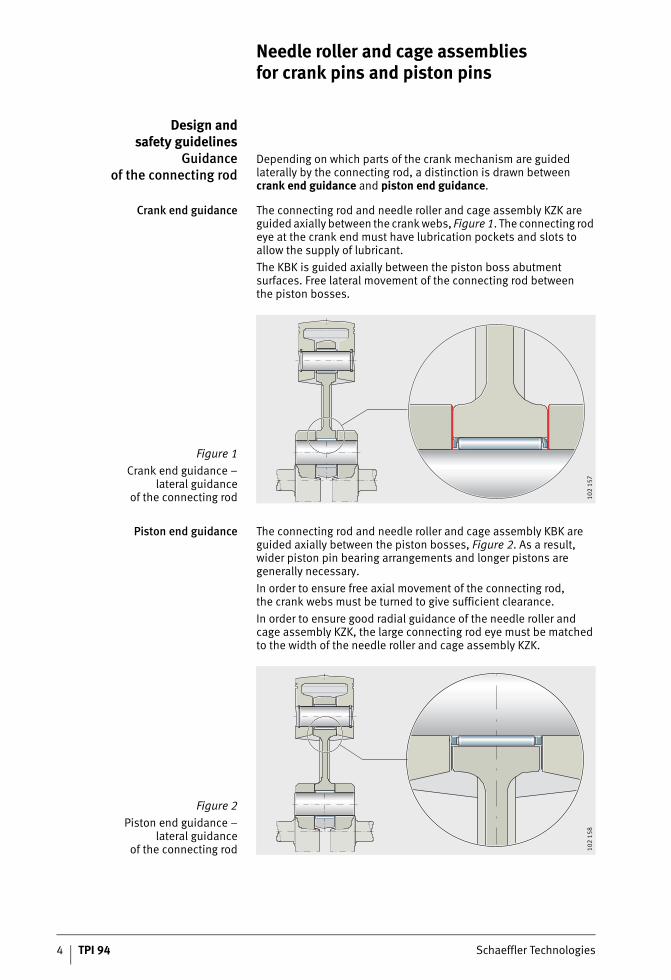
Depending on which parts of the crank mechanism are guided laterally by the connecting rod, a distinction is drawn betweencrank end guidance and piston end guidance.
Crank end guidance The connecting rod and needle roller and cage assembly KZK are guided axially between the crank webs, Figure 1. The connecting rod eye at the crank end must have lubrication pockets and slots to allow the supply of lubricant.
The KBK is guided axially between the piston boss abutment surfaces. Free lateral movement of the connecting rod betweenthe piston bosses.
Piston end guidance The connecting rod and needle roller and cage assembly KBK are guided axially between the piston bosses, Figure 2. As a result, wider piston pin bearing arrangements and longer pistons are generally necessary.
In order to ensure free axial movement of the connecting rod,the crank webs must be turned to give sufficient clearance.
In order to ensure good radial guidance of the needle roller andcage assembly KZK, the large connecting rod eye must be matched to the width of the needle roller and cage assembly KZK.
Figure 1
Crank end guidance –lateral guidance
of the connecting rod 102
157
Figure 2
Piston end guidance –lateral guidance
of the connecting rod 102
158

Schaeffler Technologies TPI 94 5
Design of adjacent parts The bores and pins for the needle roller and cage assemblies must be produced as rolling bearing raceways. A roughness Rz1 (Ra0,2) must be ensured.
The rolling bearing raceways, thrust surfaces and thrust washers must be as follows:■ case hardened to at least 0,5 mm deep;
a surface hardness of at least 700 HV must be ensured.
■ The lateral thrust surfaces should be precision machined(Ra2 recommended) and wear resistant; thrust washers should be fitted if necessary.
For lubrication of the needle roller and cage assemblies, holes or lubrication pockets should be provided, with additional lubrication slots for the crank end guidance.
Materials should be selected in accordance with the following table.
Proven materials for adjacent parts
Preferred enveloping circlediameter of needle roller and
cage assemblies
The dimensions of the needle roller and cage assemblies KZK and KBK are determined by factors including the capacity of the cylinder.
The table below for 2 stroke engines shows the preferred enveloping circle diameters Fw of needle roller and cage assemblies for proven diameters of crank pins and piston pins. Other enveloping circle diameters may be available if sufficient quantities are required.
In order to design needle roller and cage assemblies for a specific engine, the technical data of the engine must be taken into consideration. The datasheets, page 13 to page 15, must be completed and returned to us.
Proven enveloping circle diametersfor 2 stroke engines
In order to determine the crank pin diameter for 4 stroke engines,the technical data of the engine are required, see datasheets,page 13 to page 15.
Adjacent part Material
Connecting rod 16MnCr5, 15CrNi6
Crank pin 15Cr3, 17Cr3, 15CrNi6
Piston pin Ck15, 15Cr3, 17Cr3
Capacity per cylinder Enveloping circle for
KZK KBK
cm3Fwmm
Fwmm
incl. 35 8 to 14 8 to 12
over 35 incl. 50 12 to 16 10 to 12
over 50 incl. 100 16 to 20 12 to 14
over 100 incl. 150 18 to 22 14 to 16
over 150 incl. 200 22 to 24 16 to 18
over 200 incl. 300 24 to 28 18 to 22
over 300 28 min. 20 min.
6 TPI 94 Schaeffler Technologies
Needle roller and cage assembliesfor crank pins and piston pins
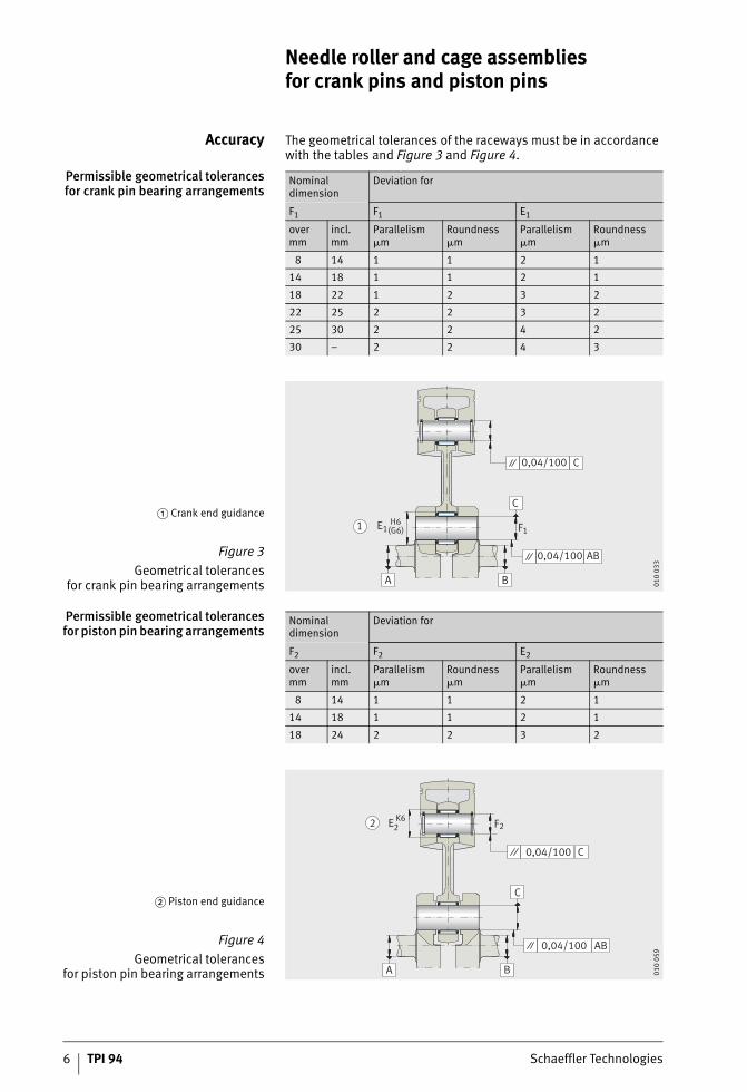
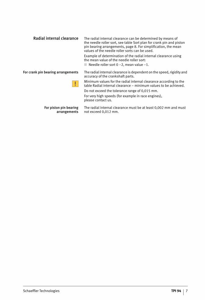
Accuracy The geometrical tolerances of the raceways must be in accordance with the tables and Figure 3 and Figure 4.
Permissible geometrical tolerancesfor crank pin bearing arrangements
Permissible geometrical tolerancesfor piston pin bearing arrangements
Nominal dimension
Deviation for
F1 F1 E1
overmm
incl.mm
Parallelism�m
Roundness�m
Parallelism�m
Roundness�m
8 14 1 1 2 1
14 18 1 1 2 1
18 22 1 2 3 2
22 25 2 2 3 2
25 30 2 2 4 2
30 – 2 2 4 3
� Crank end guidance
Figure 3
Geometrical tolerancesfor crank pin bearing arrangements
F1
0,04/100 AB
0,04/100 C
C
A B
1 (G6)H6E1
010
033
Nominal dimension
Deviation for
F2 F2 E2
overmm
incl.mm
Parallelism�m
Roundness�m
Parallelism�m
Roundness�m
8 14 1 1 2 1
14 18 1 1 2 1
18 24 2 2 3 2
� Piston end guidance
Figure 4
Geometrical tolerancesfor piston pin bearing arrangements
2E K6F2
0,04/100 AB
0,04/100 C
C
A B
2
010
059
Schaeffler Technologies TPI 94 7
Radial internal clearance The radial internal clearance can be determined by means ofthe needle roller sort, see table Sort plan for crank pin and piston pin bearing arrangements, page 8. For simplification, the mean values of the needle roller sorts can be used.
Example of determination of the radial internal clearance usingthe mean value of the needle roller sort:■ Needle roller sort 0 –2, mean value –1.
For crank pin bearing arrangements The radial internal clearance is dependent on the speed, rigidity and accuracy of the crankshaft parts.
Minimum values for the radial internal clearance according to the table Radial internal clearance – minimum values to be achieved.
Do not exceed the tolerance range of 0,015 mm.
For very high speeds (for example in race engines),please contact us.
For piston pin bearingarrangements
The radial internal clearance must be at least 0,002 mm and must not exceed 0,012 mm.
8 TPI 94 Schaeffler Technologies
Needle roller and cage assembliesfor crank pins and piston pins
Sort planfor crank pin bearing
arrangements
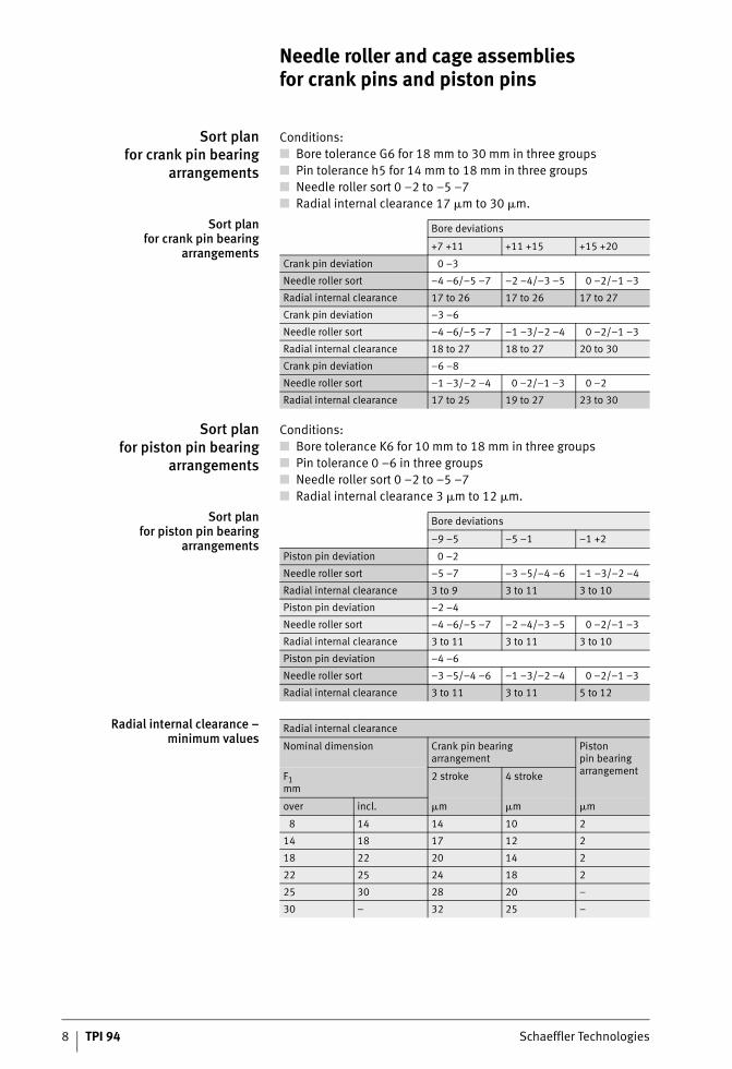
Conditions:■ Bore tolerance G6 for 18 mm to 30 mm in three groups■ Pin tolerance h5 for 14 mm to 18 mm in three groups■ Needle roller sort 0 –2 to –5 –7■ Radial internal clearance 17 �m to 30 �m.
Sort planfor crank pin bearing
arrangements
Sort planfor piston pin bearing
arrangements
Conditions:■ Bore tolerance K6 for 10 mm to 18 mm in three groups■ Pin tolerance 0 –6 in three groups■ Needle roller sort 0 –2 to –5 –7■ Radial internal clearance 3 �m to 12 �m.
Sort planfor piston pin bearing
arrangements
Radial internal clearance –minimum values
Bore deviations
+7 +11 +11 +15 +15 +20
Crank pin deviation 0 –3
Needle roller sort –4 –6/–5 –7 –2 –4/–3 –5 0 –2/–1 –3
Radial internal clearance 17 to 26 17 to 26 17 to 27
Crank pin deviation –3 –6
Needle roller sort –4 –6/–5 –7 –1 –3/–2 –4 0 –2/–1 –3
Radial internal clearance 18 to 27 18 to 27 20 to 30
Crank pin deviation –6 –8
Needle roller sort –1 –3/–2 –4 0 –2/–1 –3 0 –2
Radial internal clearance 17 to 25 19 to 27 23 to 30
Bore deviations
–9 –5 –5 –1 –1 +2
Piston pin deviation 0 –2
Needle roller sort –5 –7 –3 –5/–4 –6 –1 –3/–2 –4
Radial internal clearance 3 to 9 3 to 11 3 to 10
Piston pin deviation –2 –4
Needle roller sort –4 –6/–5 –7 –2 –4/–3 –5 0 –2/–1 –3
Radial internal clearance 3 to 11 3 to 11 3 to 10
Piston pin deviation –4 –6
Needle roller sort –3 –5/–4 –6 –1 –3/–2 –4 0 –2/–1 –3
Radial internal clearance 3 to 11 3 to 11 5 to 12
Radial internal clearance
Nominal dimension Crank pin bearingarrangement
Pistonpin bearing arrangementF1
mm2 stroke 4 stroke
over incl. �m �m �m
8 14 14 10 2
14 18 17 12 2
18 22 20 14 2
22 25 24 18 2
25 30 28 20 –
30 – 32 25 –
Schaeffler Technologies TPI 94 9
Special designs Needle roller and cage assemblies KZK are available by agreement in the following designs:■ split cage, suffix D■ copper plated cage, suffix CU■ silver plated cage, suffix AG■ for high performance machines.
Ordering example andordering designation
Needle roller and cage assembly KZK for:■ crank pin 16 mm■ connecting rod bore 22 mm■ width 12 mm■ needle roller sorts (sort pair coded blue) –2 –4 and –3 –5■ copper plated cage.
Ordering designation:■ KZK16�22�12 SORT–2–4/–3–5–CU
10 TPI 94 Schaeffler Technologies
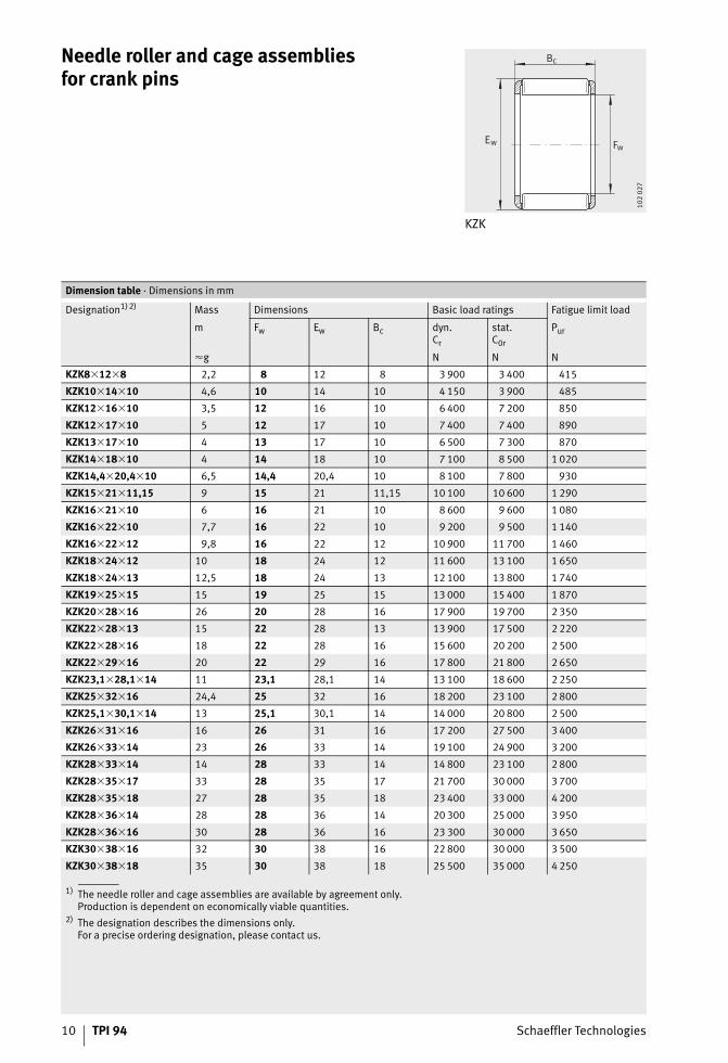
Needle roller and cage assembliesfor crank pins
KZK
Bc
Ew Fw
102
027
1) The needle roller and cage assemblies are available by agreement only.Production is dependent on economically viable quantities.
2) The designation describes the dimensions only.For a precise ordering designation, please contact us.
Dimension table · Dimensions in mm
Designation1)2) Mass Dimensions Basic load ratings Fatigue limit load
m Fw Ew Bc dyn.Cr
stat.C0r
Pur
�g N N N
KZK8�12�8 2,2 8 12 8 3 900 3 400 415
KZK10�14�10 4,6 10 14 10 4 150 3 900 485
KZK12�16�10 3,5 12 16 10 6 400 7 200 850
KZK12�17�10 5 12 17 10 7 400 7 400 890
KZK13�17�10 4 13 17 10 6 500 7 300 870
KZK14�18�10 4 14 18 10 7 100 8 500 1 020
KZK14,4�20,4�10 6,5 14,4 20,4 10 8 100 7 800 930
KZK15�21�11,15 9 15 21 11,15 10 100 10 600 1 290
KZK16�21�10 6 16 21 10 8 600 9 600 1 080
KZK16�22�10 7,7 16 22 10 9 200 9 500 1 140
KZK16�22�12 9,8 16 22 12 10 900 11 700 1 460
KZK18�24�12 10 18 24 12 11 600 13 100 1 650
KZK18�24�13 12,5 18 24 13 12 100 13 800 1 740
KZK19�25�15 15 19 25 15 13 000 15 400 1 870
KZK20�28�16 26 20 28 16 17 900 19 700 2 350
KZK22�28�13 15 22 28 13 13 900 17 500 2 220
KZK22�28�16 18 22 28 16 15 600 20 200 2 500
KZK22�29�16 20 22 29 16 17 800 21 800 2 650
KZK23,1�28,1�14 11 23,1 28,1 14 13 100 18 600 2 250
KZK25�32�16 24,4 25 32 16 18 200 23 100 2 800
KZK25,1�30,1�14 13 25,1 30,1 14 14 000 20 800 2 500
KZK26�31�16 16 26 31 16 17 200 27 500 3 400
KZK26�33�14 23 26 33 14 19 100 24 900 3 200
KZK28�33�14 14 28 33 14 14 800 23 100 2 800
KZK28�35�17 33 28 35 17 21 700 30 000 3 700
KZK28�35�18 27 28 35 18 23 400 33 000 4 200
KZK28�36�14 28 28 36 14 20 300 25 000 3 950
KZK28�36�16 30 28 36 16 23 300 30 000 3 650
KZK30�38�16 32 30 38 16 22 800 30 000 3 500
KZK30�38�18 35 30 38 18 25 500 35 000 4 250
Schaeffler Technologies TPI 94 11
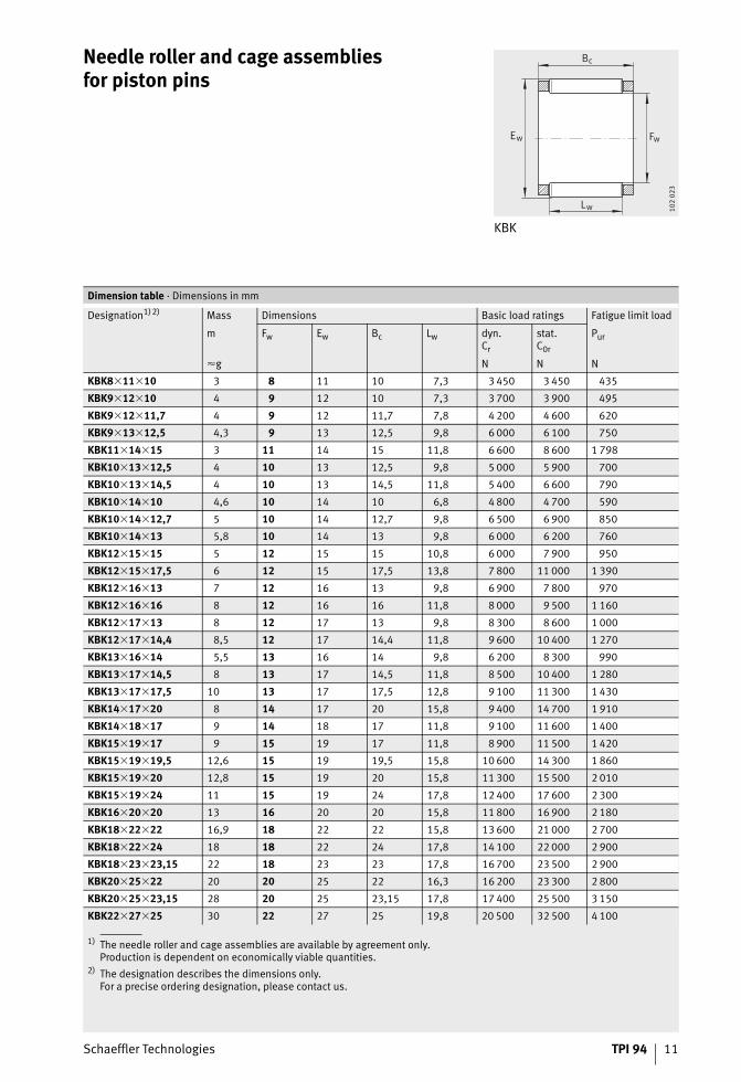
Needle roller and cage assembliesfor piston pins
KBK
Bc
Ew Fw
Lw 102
023
1) The needle roller and cage assemblies are available by agreement only.Production is dependent on economically viable quantities.
2) The designation describes the dimensions only.For a precise ordering designation, please contact us.
Dimension table · Dimensions in mm
Designation1)2) Mass Dimensions Basic load ratings Fatigue limit load
m Fw Ew Bc Lw dyn.Cr
stat.C0r
Pur
�g N N N
KBK8�11�10 3 8 11 10 7,3 3 450 3 450 435
KBK9�12�10 4 9 12 10 7,3 3 700 3 900 495
KBK9�12�11,7 4 9 12 11,7 7,8 4 200 4 600 620
KBK9�13�12,5 4,3 9 13 12,5 9,8 6 000 6 100 750
KBK11�14�15 3 11 14 15 11,8 6 600 8 600 1 798
KBK10�13�12,5 4 10 13 12,5 9,8 5 000 5 900 700
KBK10�13�14,5 4 10 13 14,5 11,8 5 400 6 600 790
KBK10�14�10 4,6 10 14 10 6,8 4 800 4 700 590
KBK10�14�12,7 5 10 14 12,7 9,8 6 500 6 900 850
KBK10�14�13 5,8 10 14 13 9,8 6 000 6 200 760
KBK12�15�15 5 12 15 15 10,8 6 000 7 900 950
KBK12�15�17,5 6 12 15 17,5 13,8 7 800 11 000 1 390
KBK12�16�13 7 12 16 13 9,8 6 900 7 800 970
KBK12�16�16 8 12 16 16 11,8 8 000 9 500 1 160
KBK12�17�13 8 12 17 13 9,8 8 300 8 600 1 000
KBK12�17�14,4 8,5 12 17 14,4 11,8 9 600 10 400 1 270
KBK13�16�14 5,5 13 16 14 9,8 6 200 8 300 990
KBK13�17�14,5 8 13 17 14,5 11,8 8 500 10 400 1 280
KBK13�17�17,5 10 13 17 17,5 12,8 9 100 11 300 1 430
KBK14�17�20 8 14 17 20 15,8 9 400 14 700 1 910
KBK14�18�17 9 14 18 17 11,8 9 100 11 600 1 400
KBK15�19�17 9 15 19 17 11,8 8 900 11 500 1 420
KBK15�19�19,5 12,6 15 19 19,5 15,8 10 600 14 300 1 860
KBK15�19�20 12,8 15 19 20 15,8 11 300 15 500 2 010
KBK15�19�24 11 15 19 24 17,8 12 400 17 600 2 300
KBK16�20�20 13 16 20 20 15,8 11 800 16 900 2 180
KBK18�22�22 16,9 18 22 22 15,8 13 600 21 000 2 700
KBK18�22�24 18 18 22 24 17,8 14 100 22 000 2 900
KBK18�23�23,15 22 18 23 23 17,8 16 700 23 500 2 900
KBK20�25�22 20 20 25 22 16,3 16 200 23 300 2 800
KBK20�25�23,15 28 20 25 23,15 17,8 17 400 25 500 3 150
KBK22�27�25 30 22 27 25 19,8 20 500 32 500 4 100
12 TPI 94 Schaeffler Technologies
AppendixCalculation of rolling bearings
in crank machinesOur calculation method can be used to calculate the basic rating life L10 of the bearings (needle roller and cage assembliesfor crank pins and piston pins, main bearings) in the crank mechanism of internal combustion engines on the basis of DIN ISO 281. In comparison with the standardised calculation to DIN ISO 281, it additionally takes into consideration the influenceof internal load distribution in the bearing on the rating life.The calculation method takes account of dynamic loading(gas forces and inertia, external forces acting on the crankshaft)and the movement functions in crank machines.
Simplifications underlying the calculation model:■ the crankshaft is only subjected to power train units of identical
load and geometry, articulated connecting rods are not taken into consideration
■ statically determinate crankshaft bearing arrangement withtwo bearings
■ no account taken of lubrication influences
■ no account taken of geometrical imperfections and deformations of the surrounding parts.
Adjusted reference rating life It is also possible to calculate the adjusted reference rating life Lnmr in accordance with DIN ISO 281, Appendix 4. This calculation method additionally incorporates the fatigue limit load ofthe material, the lubrication conditions and the type and sizeof contamination. Further data is required in this case.Please contact the Schaeffler engineering service.
Fatigue theory as a principle The rating life calculation standardised in ISO 281 is basedon Lundberg and Palmgren’s fatigue theory which always givesa final rating life.
However, modern, high quality bearings can exceed bya considerable margin the values calculated in accordance withthe standard ISO 281 under favourable operating conditions. Ioannides and Harris have developed a further model of fatigue in rolling contact that expands on the Lundberg/Palmgren theory and gives a better description of the performance capability of modern bearings.
The calculation methods are described in detail in Catalogue HR1, Rolling Bearings.
Datasheets,functional diagram
The following datasheets, page 13 to page 15 are used to collect all the data relevant to the calculation.
Needle roller and cage assembliesfor crank pins and piston pins
Schaeffler Technologies TPI 94 13
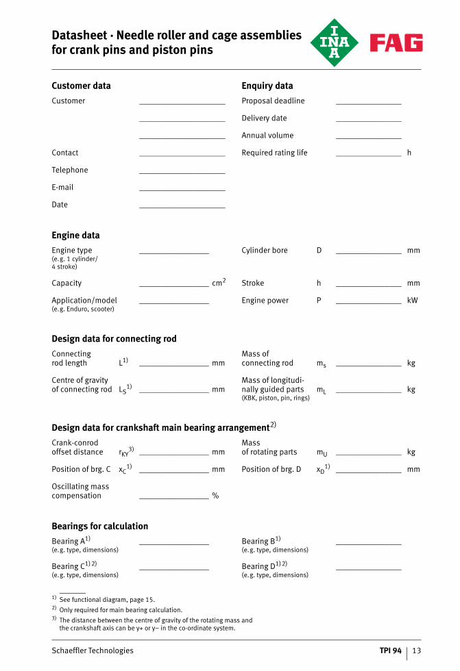
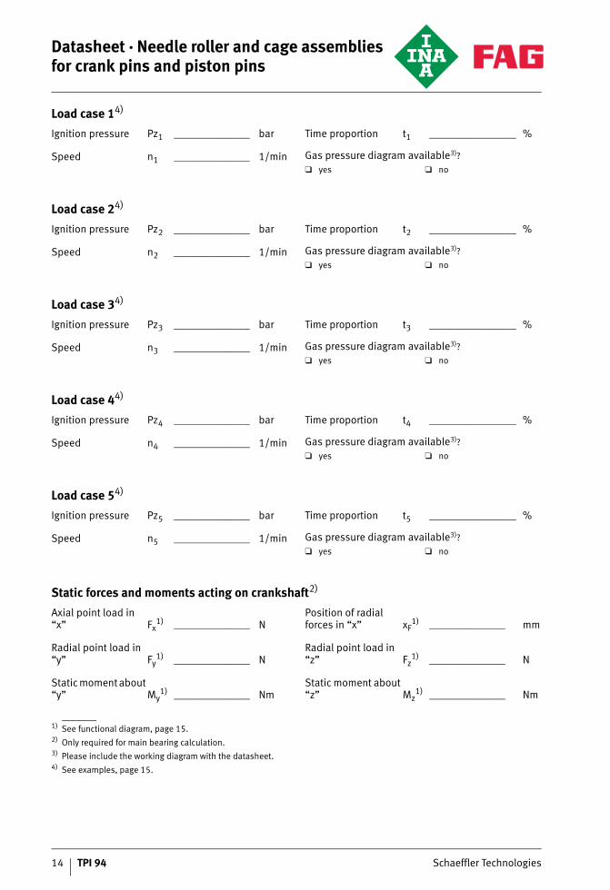
Datasheet · Needle roller and cage assemblies for crank pins and piston pins
1) See functional diagram, page 15.2) Only required for main bearing calculation.3) The distance between the centre of gravity of the rotating mass and
the crankshaft axis can be y+ or y– in the co-ordinate system.
Customer data Enquiry data
Customer _____________________ Proposal deadline ________________
_____________________ Delivery date ________________
_____________________ Annual volume ________________
Contact _____________________ Required rating life ________________ h
Telephone _____________________
E-mail _____________________
Date _____________________
Engine data
Engine type(e.g. 1 cylinder/4 stroke)
_________________ Cylinder bore D ________________ mm
Capacity _________________ cm2 Stroke h ________________ mm
Application/model(e.g. Enduro, scooter)
_________________ Engine power P ________________ kW
Design data for connecting rod
Connectingrod length L1) _________________ mm
Mass ofconnecting rod ms ________________ kg
Centre of gravityof connecting rod LS
1) _________________ mmMass of longitudi-nally guided parts(KBK, piston, pin, rings)
mL ________________ kg
Design data for crankshaft main bearing arrangement2)
Crank-conrodoffset distance rKY
3) _________________ mmMassof rotating parts mU ________________ kg
Position of brg. C xC1) _________________ mm Position of brg. D xD
1) ________________ mm
Oscillating mass compensation _________________ %
Bearings for calculation
Bearing A1)
(e.g. type, dimensions)_________________ Bearing B1)
(e.g. type, dimensions)________________
Bearing C1)2)
(e.g. type, dimensions)_________________ Bearing D1)2)
(e.g. type, dimensions)________________
14 TPI 94 Schaeffler Technologies
1) See functional diagram, page 15.2) Only required for main bearing calculation.3) Please include the working diagram with the datasheet.4) See examples, page 15.
Load case 14)
Ignition pressure Pz1 ______________ bar Time proportion t1 ________________ %
Speed n1 ______________ 1/min Gas pressure diagram available3)?
❑ yes ❑ no
Load case 24)
Ignition pressure Pz2 ______________ bar Time proportion t2 ________________ %
Speed n2 ______________ 1/min Gas pressure diagram available3)?
❑ yes ❑ no
Load case 34)
Ignition pressure Pz3 ______________ bar Time proportion t3 ________________ %
Speed n3 ______________ 1/min Gas pressure diagram available3)?
❑ yes ❑ no
Load case 44)
Ignition pressure Pz4 ______________ bar Time proportion t4 ________________ %
Speed n4 ______________ 1/min Gas pressure diagram available3)?
❑ yes ❑ no
Load case 54)
Ignition pressure Pz5 ______________ bar Time proportion t5 ________________ %
Speed n5 ______________ 1/min Gas pressure diagram available3)?
❑ yes ❑ no
Static forces and moments acting on crankshaft2)
Axial point load in “x” Fx
1) ______________ NPosition of radial forces in “x” xF
1) ______________ mm
Radial point load in “y” Fy
1) ______________ NRadial point load in “z” Fz
1) ______________ N
Static moment about “y” My
1) ______________ NmStatic moment about “z” Mz
1) ______________ Nm
Datasheet · Needle roller and cage assemblies for crank pins and piston pins
Schaeffler Technologies TPI 94 15
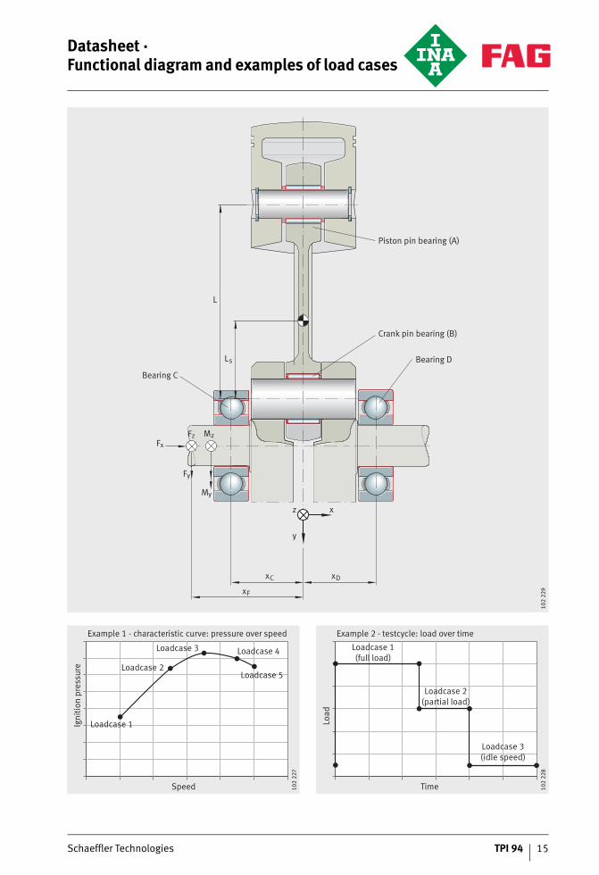
Datasheet ·Functional diagram and examples of load cases
Piston pin bearing (A)
Crank pin bearing (B)
Bearing D
Bearing C
z x
y
FF
F
zx
y
M
M
z
y
xF
xC xD
Ls
L
102
229
Example 1 - characteristic curve: pressure over speed
Speed
Igni
tion
pre
ssur
e
Loadcase 1
Loadcase 2
Loadcase 3 Loadcase 4
Loadcase 5
102
227
Example 2 - testcycle: load over time
Time
Loa
d
Loadcase 1(full load)
Loadcase 2(partial load)
Loadcase 3(idle speed)
102
228

Schaeffler TechnologiesAG & Co. KG
Industriestraße 1–391074 HerzogenaurachGermanyInternet www.ina.comE-mail [email protected]
In Germany:Phone 0180 5003872Fax 0180 5003873
From other countries:Phone +49 9132 82-0Fax +49 9132 82-4950
Every care has been taken to ensure the
correctness of the information contained
in this publication but no liability can be
accepted for any errors or omissions.
We reserve the right to make technical
changes.
© Schaeffler Technologies AG & Co. KG
Issued: 2013, March
This publication or parts thereof may not
be reproduced without our permission.
TPI 94 GB-DMAT
NR
0069
8429
0-00
00 /
TPI
94
/ G
B-D
/ 2
0130
31 /
Prin
ted
in G
erm
any
by b
resl
er