ncree newsletter volume 10 number 3 september 2015
TRANSCRIPT


1
NCREE Newsletter Volume 10 Number 3 September 2015
1
Research and Development on Lightweight Composite Bridge for Emergency Disaster Relief Fang-Yao Yeh, Hsiao-Hui Hung, Research Fellow, NCREE
Kuo-Chun Chang, National Taiwan University Yu-Chi Sung, National Taipei University of Technology
Introduction
Owing to recent extreme climates, typhoons, floods, and earthquakes have become large natural disaster threats in Taiwan over the years. Such natural disasters have caused damage to some bridges, consequently isolating residential communities located on mountains and hampering the ability to deliver emergency relief supplies to those communities. In order to provide rapid emergency relief, the simple construction of a temporary bridge becomes critical for the transportation of food and medical supplies into the emergency disaster areas. While composite materials for footbridges and vehicular traffic applications have been widely used overseas, they are not suitable for disaster relief applications. The objective of this paper is to present a novel bridge structure for a portable, reusable, and lightweight bridge. This paper focuses on the design concept and experimental verification of a temporary composite bridge for disaster relief. Ultimately, it advocates composite bridges for disaster relief applications.
Concept and Innovation of Temporary Bridge
This study develops a temporary bridge system by using a self-weight balance approach and a cantilever incremental launching method. An asymmetric self-anchored cable-stayed bridge is proposed. The structural segments constructed by heavyweight materials (e.g., steel and concrete) are used as counter-weights at the rescue end and the cross-river segments are constructed by lightweight materials (e.g., composite materials) in order to increase the span to easily reach the isolated island end without any supports or foundations (Fig. 1)
The advantages of this composite bridge include the following: (1) during the construction stage, the asymmetric self-anchored cable-stayed bridge is easily constructed from the rescue end to the isolated island end by using the self-weight balance of heavyweight structural segments and lightweight cross-river segments. The wires of the cable-stayed bridge are helpful in the construction of the cross-river segments via the cantilever incremental launching method (Fig. 1a); further, (2) during the commissioning completion stage, these wires are effective in reducing the deformation of the bridge caused by live loads from traffic (Fig. 1b).
(b) The commissioning completion stage
Fig. 1. Innovation and concept of a composite bridge for emergency disaster relief
Design of Temporary Composite Bridge
We designed a steel-composite cable-stayed bridge with a span of 20 m, a width of 3 m, and a live load of 5 tons (for transportation of rescue goods via a truck weighing 3.5 tons), and a deflection-to-span ratio of L/400 for the assembled and river-crossing test. Fig. 2 shows the design results of the asymmetric self-anchored cable-stayed bridge. Seven parallel steel girders and H-shape pillars with a 294 mm × 200 mm × 8 mm × 12 mm cross section on the A1 side abutment were used as the weight balance structural module, five parallel FRP girders using glass-fiber reinforced plastic (GFRP) with a 410 mm × 200 mm × 18 mm × 20 mm cross section were used as the crossing structural module, and double-H-shape steel cross beams were used to aid the crossing of the river (Fig. 2a and 2b). We used a steel frame on the A1 side abutment as a counterweight and a cable-stayed type bridge to quickly assemble the lightweight GFRP temporary bridge via the incremental launching method to cross the river and therefore achieve the goal of providing disaster relief.
(a) Front view
(b) 3D view Fig. 2. Design results of the 20 m span temporary composite bridge
Construction Sequences and River-cross Tests
The lightweight temporary composite bridge system included a weight balance structural module, a bridge
Heavy-weight material structure
20~40 m10 m
Light-weight material structure
(a) The construction stage
20~40 m 10 m
River
A1 A2
3@4m=12m 5@4m=20m
20m
River
A1 A2
3@4m=12m 5@4m=20m
20m
2
NCREE Newsletter Volume 10 Number 3 September 2015
2
(b) (a)
(b) (a)
tower structural module, a crossing structural module, and connection cables. The weight balance structural module and the bridge tower structural module were constructed of steel, concrete, and any other heavyweight materials as the structural segments. The crossing structural module was constructed of composites and any other lightweight materials. The construction sequences were as follows: (1) assemble the structural segments to complete the weight balance structural module (Fig. 3a); (2) assemble the structural segments to complete the bridge tower structural module, fix the bottom part to the weight balance structural module, and couple the top part to the weight balance structural module via at least one connection cable (Fig. 3b); and (3) assemble the crossing segments between the rescue end and the isolated island end gap (Fig. 3c) to complete the crossing structural module and couple it to the top part of the bridge tower structural module via at least one connection cable (Fig. 3d).
(a)
(b)
(c)
(d)
Fig. 3. Construction sequences of composite bridge
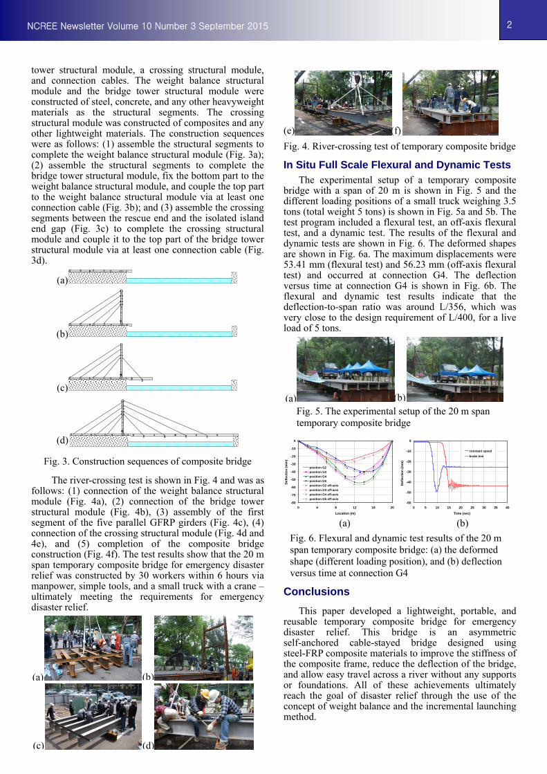
The river-crossing test is shown in Fig. 4 and was as follows: (1) connection of the weight balance structural module (Fig. 4a), (2) connection of the bridge tower structural module (Fig. 4b), (3) assembly of the first segment of the five parallel GFRP girders (Fig. 4c), (4) connection of the crossing structural module (Fig. 4d and 4e), and (5) completion of the composite bridge construction (Fig. 4f). The test results show that the 20 m span temporary composite bridge for emergency disaster relief was constructed by 30 workers within 6 hours via manpower, simple tools, and a small truck with a crane – ultimately meeting the requirements for emergency disaster relief.
(e) (f)
Fig. 4. River-crossing test of temporary composite bridge
In Situ Full Scale Flexural and Dynamic Tests The experimental setup of a temporary composite
bridge with a span of 20 m is shown in Fig. 5 and the different loading positions of a small truck weighing 3.5 tons (total weight 5 tons) is shown in Fig. 5a and 5b. The test program included a flexural test, an off-axis flexural test, and a dynamic test. The results of the flexural and dynamic tests are shown in Fig. 6. The deformed shapes are shown in Fig. 6a. The maximum displacements were 53.41 mm (flexural test) and 56.23 mm (off-axis flexural test) and occurred at connection G4. The deflection versus time at connection G4 is shown in Fig. 6b. The flexural and dynamic test results indicate that the deflection-to-span ratio was around L/356, which was very close to the design requirement of L/400, for a live load of 5 tons.
Fig. 5. The experimental setup of the 20 m span temporary composite bridge
(a) (b)
Fig. 6. Flexural and dynamic test results of the 20 m span temporary composite bridge: (a) the deformed shape (different loading position), and (b) deflection versus time at connection G4
Conclusions
This paper developed a lightweight, portable, and reusable temporary composite bridge for emergency disaster relief. This bridge is an asymmetric self-anchored cable-stayed bridge designed using steel-FRP composite materials to improve the stiffness of the composite frame, reduce the deflection of the bridge, and allow easy travel across a river without any supports or foundations. All of these achievements ultimately reach the goal of disaster relief through the use of the concept of weight balance and the incremental launching method.
(d) (c)
-80
-70
-60
-50
-40
-30
-20
-10
0
0 4 8 12 16 20
Location (m)
De
fle
ctio
n (
mm
)
position G2
position G3
position G4
position G5
position G2 off-axis
position G3 off-axis
position G4 off-axis
position G5 off-axis-60
-50
-40
-30
-20
-10
0
0 5 10 15 20 25 30 35 40
Time (sec)
Def
lec
tio
n (
mm
)
constant speed
brake test

3
NCREE Newsletter Volume 10 Number 3 September 2015
3
Experimental Study of Precast Segmental Bridge Piers with Shear Resistance Provided by Shear Keys
Hsiao-Hui Hung, Chi-Rung Jiang, NCREE Yu-Chi Sung, Kuan-Chen Lin, National Taipei University of Technology
Since the use of precast segmental technology allows
bridge engineers to reduce traffic disruptions, minimize environmental impact, and increase the speed of construction, it has been applied to bridge construction worldwide in recent times. Nowadays, the most commonly used precast segmental technology for substructures is the post-tensioned precast segmental column. For this, a high value of post-tensioning is typically adopted for the precast segments to provide sufficient axial force that imposes friction between the neighboring segments. The prestressing force can provide resistance against shear stress caused by an external force and also provide re-centering force. However, as the bridge column bears large axial forces with even no external force applied thereto, it may cause adverse effects on the ductility of the bridge column and may therefore result in excessive stress on the precast segments. For the reasons stated above, by extracting the concept of the human spinal column, a semi-rigid connection for the precast segmental bridge pier system was proposed in this study. The proposed connection between segments is a hybrid connection containing bonded bar reinforcement that is spliced by bar couplers and shear keys to provide shear resistance between neighboring segments. Unbounded tendons with a small prestressing force could also be included to provide re-centering forces.
In this study, two types of connection between each prefabricated element were proposed. One is a steel dowel shear key and the other is a RC shear key as given in Fig.1. To investigate the seismic performance of both types of connection, three precast segmental column specimens with different prestressing forces for each type were constructed and tested at the National Center for Research on Earthquake Engineering (NCREE). For the columns with the steel dowel shear key, the specimens were denoted by SSK-P0, SSK-P1, and SSK-P2. For the columns with the RC shear key, the specimens were denoted by RCSK-P0, RCSK-P1, and RCSK-P2, where P0 represents zero prestressing force, P1 and P2 represent a prestressing force of 0.025fc
’Ag and 0.05fc
’Ag, respectively. For comparison, a conventional cast-in-place column specimen without connections (BM01) was also constructed and tested.
Cyclic loading tests were conducted on all 7 specimens at NCREE. During the test, a constant axial load of 0.1 fc
’Ag was applied to the test column through a tap beam to simulate the tributary dead load of the deck. Fig. 2 shows the load-displacement hysteretic curve for each specimen. These figures show that the precast segmental columns without the prestressing tendon can not only emulate the hysteretic behavior of the conventional column, it also has a better ductility capacity. In addition, with an increase in the prestressing
forces, the residual displacements have a tendency to be reduced, especially for the precast columns with steel dowel shear keys. However, the increase in the post-tensioned prestressing force was also accompanied by a slight reduction in ductility capacity of the column due to the increase in the axial forces. From the experimental results and construction practices of the developed system, the high seismic resistance and the satisfactory constructability of the proposed pier was confirmed.
Fig. 1. Design details of the specimen
(a) Conventional column (BM01)
(b) Precast columns with steel dowel shear key (SSK)
(c) Precast columns with RC shear key (RCSK) Fig.2. Experimental results
Displacement(mm)
-360 -240 -120 0 120 240 360
La
tera
l fo
rce(
kN)
-300
-200
-100
0
100
200
300
-300
-200
-100
0
100
200
300
Drift(%)
-10 -8 -6 -4 -2 0 2 4 6 8 10
Displacement(mm)
-360 -240 -120 0 120 240 360
La
tera
l fo
rce(
kN)
-300
-200
-100
0
100
200
300
-3
-2
-
0
2
3
Drift(%)
-10 -8 -6 -4 -2 0 2 4 6 8 10
SSK-P0
Displacement(mm)
-360 -240 -120 0 120 240 360
La
tera
l fo
rce(
kN)
-300
-200
-100
0
100
200
300
-
-2
-
2
Drift(%)
-10 -8 -6 -4 -2 0 2 4 6 8 10
SSK-P1
Displacement(mm)
-360 -240 -120 0 120 240 360
La
tera
l fo
rce(
kN)
-300
-200
-100
0
100
200
300
-
-2
-
2
Drift(%)
-10 -8 -6 -4 -2 0 2 4 6 8 10
SSK-P2
Displacement(mm)
-360 -240 -120 0 120 240 360
La
tera
l fo
rce(
kN)
-300
-200
-100
0
100
200
300
-3
-2
-1
0
1
2
3
Drift(%)
-10 -8 -6 -4 -2 0 2 4 6 8 10
RCSK-P0
Displacement(mm)
-360 -240 -120 0 120 240 360
La
tera
l fo
rce(
kN)
-300
-200
-100
0
100
200
300
-3
-2
-1
0
1
2
3
Drift(%)
-10 -8 -6 -4 -2 0 2 4 6 8 10
RCSK-P1
Displacement(mm)
-360 -240 -120 0 120 240 360
La
tera
l fo
rce(
kN)
-300
-200
-100
0
100
200
300
-
-
-
Drift(%)
-10 -8 -6 -4 -2 0 2 4 6 8 10
RCSK-P2
900
2800
3940
40
900
500
700
50
50
740
Strands anchorages
S1
S2
S3
Segment 4
600
1350
D13@175
Hoop8-D13
2250
Couplers for Rebars
Couplers for Rebars
Side View
Unit: mm
Spirals
3600
Loading Point
20
She
Sp
350
Φ4-Steel Bars
Steel groove
Shear stud 100Spirals
RC shear key
300
RC groove
Spirals
Steel dowel shear key
RC shear key

4
NCREE Newsletter Volume 10 Number 3 September 2015
4
Sensor Layout Discussion of Fiber Optics Differential Settlement Sensor on Railway Monitoring
Zheng-Kuan Lee, Jingo Chen, Lu-Sheng Lee, NCREE
An optical fiber grating (Fiber Bragg grating, FBG) can be perceived as a light wave filter that reflects the light of specific wavelengths λB while enabling the light waves of other wavelengths to pass, transmit, and reflect after reaching the next grating (shown in Fig. 1).
Fig. 1. Various wavelengths of input light waves filtered through FBGs
As shown in Fig. 2, when the red grating is under tension, it slightly elongates, changing the reflected light from red to magenta. When the red grating is under compression, it slightly contracts, changing the reflected light from red to dark red. According to the wavelength variation, the specific grating under tension or compression and loading (g) thereof can be determined. According to definite relationships between wavelength variations and tensile or compressive loads, mechanistic encapsulation can be combined with other physical principles to manufacture gratings into various sensor instruments, such as the fiber optics settlement profiler, which is described as follows.
Fig. 2. Behavior of “Red” FBG under Stress
The fiber optics Differential Settlement Sensor is an instrument constructed using the fiber elasticity assumption, connected pipe principle, and buoyancy principle.
As shown in Fig. 3, when the right container rises, the fluid level on the left also rises. Consequently, the tension on the left FBG decreases, shortening the reflective light wavelength. By contrast, when the right container sinks, the fluid level of the left decreases, increasing the tension on the left FBG and lengthening the reflective light wavelength. Therefore, gratings can be used to fabricate fiber optics Differential Settlement Sensor (DSM) to monitor railway subsidence.
Fig.3. FBG Fiber Optics Differential Settlement Sensor
Generally, railways ascend and descend; therefore, one single pipe connecting all DSMs will elevate the instruments higher than the roadbed of railway, affecting the safety of train operation. Consequently, the turning point approach in survey can be applied using multiple sets of DSM (Fig. 3) in the layout of Fig. 4 to form a subsidence monitoring system. This system can be used to provide subsidence information along railways during embankment maintenance or nearby construction, thereby ensuring the safety of train operation.
Fig. 4. DSM layout along a railway track
1L 1R 3L 3R 5L 5R 7L 7R
2L 2R 4L 4R 6L 6R

5
NCREE Newsletter Volume 10 Number 3 September 2015
5
Seismic Performance of New RC Circular Bridge Column Kuang-Yen, Liu, National Center for Research on Earthquake Engineering
Wen-Chun,Liao, and Zhi-Qiang Yeh, National Taiwan University
Introduction
The strength of material has increased recently, especially for the New RC project for building structures in Japan since 1988. The compressive strength of concrete has increased to at least 120 MPa with a yielding strength of reinforcement of more than 685 MPa. If high strength concrete and reinforcement, called New RC, is applied to bridge design, it is possible to reduce the dimensions and weight of the structural member in order to save space and material and to provide more free land. However, high strength concrete is a kind of brittle material. Therefore, the seismic performance of a New RC bridge should be carefully investigated. The test results of two New RC columns from the point of view of hysteresis behavior and ductility capacity are discussed.
Experimental Program
In this study, one solid and one hollow section of a circular column specimen, called NEW_D65_10T and NEW_H75_10T, respectively, were designed and tested under cyclical loading, and then compared to a benchmark circular column, RC_D76_7T, that was constructed of a conventional RC material and tested in 1999. The major design parameters of those three columns are listed in Table 1. The design target of the New RC column is to provide the same moment strength as the RC column while subjected to a similar axial load, so as to compare the reduction rate on the cross section and usage of reinforcement. The moment capacity exhibited in RC_D76_7T was 1500 kN-m. The reduction rate of the sectional area of NEW_D65_10T and NEW_H75_10T, with respect to RC_D76_7T, was around 27% and 24% smaller, respectively. For the loading protocol, the column was horizontally and cyclically pushed by the displacement control of one actuator, according to the drift ratio of the column height from 0.25%, 0.5%, 0.75%, 1.0%, 1.5%, and 2%. It was only when the lateral force was dropped 20% from the peak value, or lost its stability, or the longitudinal reinforcement ruptured, that the test was stopped.
Table 1. Design parameter of the column specimen
Specimen RC_ D76_7T
NEW_ D65_10T
NEW_ H75_10T
Height cm 325 325 325
Outer/Inner diameter
cm 76/0 65/0 75/35
f’c MPa 21 70 70
main bar
n-# cm 34-D19 16-D25 12-D25
ρl % 2.15 2.44 2.35
fy MPa 420 685 685
hoop +
Tie
#@cm cm D10@7 D13@10 D13@10
ρt % 0.93 1.35 2.49
fyt MPa 280 420 420
Axial load kN 1400 1400 1400
Experimental Results
Figure 1 represents the hysteresis loop of the three specimens. The failure mode for the New RC column was flexural with respect to the flexural-shear failure for the RC column prior to the drift ratio of 7%. The ultimate drift ratio for NEW_D65_10T, NEW_H75_10T, and RC_D76_7T was 8%, 7%, and 5%, respectively. With evidence of superior deformation capacity and satisfying energy dissipation capacity of the New RC column, the high strength concrete can be well confined if sufficient lateral reinforcement is provided and if the ratio of P/f’cAg is smaller than 0.1.
(a) (b)
Fig. 1. Comparison of the hysteresis loop
Table 2 shows the drift ratio of the specimen corresponding to yielding and ultimate states. The ultimate drift divided by the yielding drift gives displacement ductility. The displacement of all three columns was larger than the minimum requirement of 3 given in the design code. From Table 2, due to the reduction of initial lateral stiffness of NEW_D65_10T, the yielding displacement was the largest among three columns, resulting in the displacement ductility of 4.58, smaller than 5.52 of RC_D76_7T. In contrast, the displacement ductility of NEW_H75_10T reached 6.44.
Table 2. Drift ratio and displacement ductility
Specimen RC_
D76_7T
NEW_
D65_10T
NEW_
H75_10T
Δy (%) 1.00 1.75 1.16
Δmax (%) 5.54 8.00 7.47
μ 5.52 4.58 6.44
Summary
The feasibility of applying high strength concrete and high strength reinforcement (New RC) to the seismic design of a bridge column was confirmed by experimental investigation. The New RC column can satisfy the minimum requirement regarding displacement and strength, therefore decreasing self-weight and saving usage of reinforcement economically.
6
NCREE Newsletter Volume 10 Number 3 September 2015
6
The Best Anti-Seismic Solution for Our Property - Rolling-Type Seismic Isolation Devices (News Conference)
Shiang-Jung Wang, Wang-Chuen Lin, Cho-Yen Yang, Chung-Han Yu, Jenn-Shin Hwang, Kuo-Chun Chang, NCREE
Earthquakes are inevitable in Taiwan. A frequent moderate earthquake may affect regular operation of most important facilities and industries, thus, greatly impacting human life and Taiwan’s competitiveness.
When most structural elements remain intact during or after an earthquake, the desired performance of a building may not be achieved if the housed equipment or facilities are damaged. This situation has often occurred. For instance, computers, servers, data storage equipment, networks, and telecommunications of high-tech industries, telecommunication industries, banks, and emergency-response centers have not remained operational; high-precision equipment, power generators, and medical instruments of high-tech factories and hospitals have not remained functional; valuable antiques, arts, and exhibits in museums and historical research institutes have suffered serious damage.
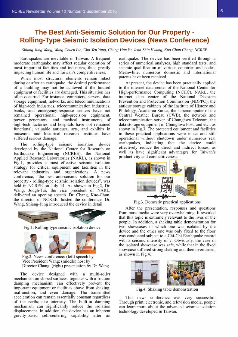
The rolling-type seismic isolation device developed by the National Center for Research on Earthquake Engineering (NCREE), the National Applied Research Laboratories (NARL), as shown in Fig.1, provides a most effective seismic isolation strategy for critical equipment and facilities in the relevant industries and organizations. A news conference, “the best anti-seismic solution for our property - rolling-type seismic isolation devices”, was held in NCREE on July 14. As shown in Fig.2, Dr. Wang, Jough-Tai, the vice president of NARL, delivered an opening speech. Dr. Chang, Kuo-Chun, the director of NCREE, hosted the conference. Dr. Wang, Shiang-Jung introduced the device in detail.
Fig.1. Rolling-type seismic isolation device
Fig.2. News conference: (left) speech by Vice President Wang; (middle) host by Director Chang; (right) presentation by Dr. Wang
The device designed with a multi-roller mechanism on sloped surfaces, together with a friction damping mechanism, can effectively prevent the important equipment or facilities above from shaking, malfunction, and even damage. The transmitted acceleration can remain essentially constant regardless of the earthquake intensity. The built-in damping mechanism can significantly reduce the isolation displacement. In addition, the device has an inherent gravity-based self-centering capability after an
earthquake. The device has been verified through a series of numerical analyses, high standard tests, and seismic qualification of various countries and codes. Meanwhile, numerous domestic and international patents have been received.
At present, the device has been practically applied to the internet data center of the National Center for High-performance Computing (NCHC), NARL, the internet data center of the National Disasters Prevention and Protection Commission (NDPPC), the antique storage cabinets of the Institute of History and Philology, Academia Sinica, the supercomputer of the Central Weather Bureau (CWB), the network and telecommunication server of Chunghwa Telecom, the data storage equipment of Chunghwa Post, and etc., as shown in Fig.3. The protected equipment and facilities in these practical applications were intact and still operational without shutdown under numerous real earthquakes, indicating that the device could effectively reduce the direct and indirect losses, as well as have significant advantages for Taiwan’s productivity and competitiveness.
Fig.3. Domestic practical applications After the presentation, responses and questions
from mass media were very overwhelming. It revealed that this topic is extremely relevant to the lives of the people. In addition, a shaking table demonstration for two showcases in which one was isolated by the device and the other one was only fixed to the floor was conducted subject to a Chi-Chi Earthquake record with a seismic intensity of 7. Obviously, the vase in the isolated showcase was safe, while that in the fixed showcase suffered strong shaking and then overturned, as shown in Fig.4.
Fig.4. Shaking table demonstration
This news conference was very successful. Through print, electronic, and television media, people can learn more about the advanced seismic isolation technology developed in Taiwan.

7
NCREE Newsletter Volume 10 Number 3 September 2015
7
Popular Science Event ReportShih-Bin Chiu, Assistant Researcher, NCREE
Zheng-Kuan Lee, Associate Researcher, NCREE
To raise public awareness on earthquake disaster mitigation and to cultivate students’ scientific spirit and interest in knowledge exploration, the center has included earthquake engineering education and dissemination as a developmental goal. Aside from converting relevant research findings into comprehensible earthquake disaster mitigation knowledge for the general public and actively promoting the knowledge through pluralistic educational means, the center also holds an international creative antiearthquake engineering competition every year and promotes seismic knowledge through newspapers, magazines and the television. In terms of educating the public about earthquake disaster mitigation measures, the center routinely receives visitors from various fields and holds lectures at primary and secondary schools, as shown in Fig.1 and Fig.2.
Fig.1. For the visitors, popular science demonstration for earthquake hazard mitigation in NCREE Conference Room
Fig.2. Teachers and students took a picture together after visiting NCREE
Most visitors are interested in earthquake engineering; they are not only curious about earthquakes, but also aware of the extent of loss of life and property in earthquakes. To help our visitors and students better understand earthquake engineering, the center has developed a series of earthquake
engineering educational resources, including models, posters, videos, and manuals, about the seriousness of earthquake disasters and the importance of taking early preventive measures to minimize loss.
This year, visitors to the center have included participants from the summer and winter camps organized by Legislator Hsueh Ling and Taipei City Counselor He Chih-Wei; members from the Atomic Energy Council; National Defense University students taking the course “Joint Disaster Mitigation and Relief Scenario Planning”; students from Taipei City Ren-ai Elementary School; New Taipei Municipal Zhongzheng Junior High School teachers and their students taking the course in disaster mitigation and education; students and teachers from Taipei Municipal Mu Zha Junior High School; and people from Taipei 101. In addition to giving a presentation on earthquake engineering, the center also demonstrated the earthquake engineering laboratory equipment (e.g., earthquake simulation table, reaction wall–strong floor test system, and the Multi-Axial Testing system, and took guests to see the seismic isolation design on the second floor of National Taiwan University Civil Engineering Research Building. The center also held an earthquake science experiential camp at Wuchuan Elementary School in Kaohsiung for students to learn about resonance and other scientific principles and conducted an antiseismic pasta house design contest for students to apply structural antiseismic principles to designing a house. Contestants were asked to construct a pasta house could resist the highest earthquake magnitude measured during the 921 earthquake; before the contest, they had to measure the load to calculate the performance and load ratio. In the end, the students successfully completed the task by designing houses that are both earthquake resistant and economical, through which they experienced the engineering philosophy of design.
Over the past century, there has been on average one disastrous earthquake in Taiwan every decade. For people in Taiwan, it is crucial for people to learn and remember these lessons from the past, recognize the danger of earthquakes, and improve their ability to handle a crisis. The center plans to continue promoting earthquake engineering education and reminding the public to be adequately prepared for the next earthquake.

8
NCREE Newsletter Volume 10 Number 3 September 2015
8
2015 International Bridge Conference and the 10th US–Taiwan Highway and Bridge Engineering Workshop
Chun-Chung Chen, Associate Researcher
The International Bridge Conference, an international conference held in the United States for bridge engineers, is cohosted by the Engineers’ Society of Western Pennsylvania and the American Road and Transportation Builders Association. This year, the conference was held at the David L. Lawrence Convention Center between June 8 and 11. Because of its long and close relationship with the United States, Taiwan was selected as the 2015 Featured Country for this event. For maximum efficiency, the 10th US–Taiwan Highway and Bridge Engineering Workshop was incorporated into the conference. For the event, three major themes were selected to promote Taiwan’s engineering and tourism and to demonstrate the government of Taiwan’s efforts and investment: Sustainability Management in Taiwan, Disaster Prevention in Taiwan, and Taiwan’s Culture and Sceneries.
The conference is a major event for the United States bridge engineering field, and it provides participants with the latest information and technologies used in bridge engineering practices in the United States. This time, Dr. Fan Chih-ku, the Deputy Minister of Ministry of Transportation and Communications, led a delegation group comprising 55 members from 20 divisions to attend and to chair the opening ceremony of the Taiwan Pavilion. During the conference, participants from all over the world praised Taiwan’s bridge and tunnel engineering quality and achievements. The main theme of this exhibition was “Safe Taiwan”, encompassing such topics as ecological restoration, carbon management in engineering, disaster prevention alarm, and special bridge erection methods that accommodate Taiwan’s natural environmental conditions. The delegation group did an excellent job in presenting Taiwan’s sophisticated bridge engineering capacity and sustainability-oriented construction outcomes.
This year, Director Chang Kuo-Chun, Division Chief Sung Yu-Chi, Research Fellow Lin Yung-Bin, and Associate Research Fellow Chen Chun-Chung represented the Center in joining the delegation group, and they attended the 10th US–Taiwan Highway and Bridge Engineering Workshop and participated in bilateral information exchange with the members from the United States on road and bridge engineering technology. Workshop participants included personnel from various branches of industry, government, and academia. They enthusiastically discussed various issues as well as the possibility of implementing collaborative bilateral projects including a bridge inspector education and training project, long-term bridge-performance research project, and compound disaster-prevention project. Taiwan’s delegation group also presented technology that has been independently researched and developed in Taiwan with the hope of
enhancing Taiwan’s international visibility and assisting Taiwanese engineers in acquiring international knowledge and skills.
Members from our center participating in the conference Dr. Chen Chun-Chung (left), Director Chang Kuo-Chun (middle), and Division Chief Sung Yu-Chi (right))
Published by National Center for Research on Earthquake Engineering 200, Sec. 3, XinHai Rd., Taipei 106, Taiwan, R.O.C. Phone: 886-2-6630-0888 Fax: 886-2-6630-0858 Website: http://newsletter.ncree.org
The National Center for Research on Earthquake Engineering (NCREE) is a laboratory of National Applied Research Laboratories (NARL) Website: http://www.narl.org.tw