navigational and guidance system
DESCRIPTION
Sensors their principle construction and application.TRANSCRIPT

INERTIAL NAVIGATION
• A navigation technique.
• Position and orientation determined using accelerometers and gyroscopes.
Accelerometers
Gyroscopes

INERTIAL NAVIGATION(CONTD.)
• Obtained data + initial position & orientation Current position and orientation.
• Unlike GPS or radar, results not compared from external frame.

MEMS• Microelectromechanical systems.
-high miniaturization and cost reduction
• Fabricated using semiconductor device fabrication technologies.
• Can be integrated with electronics to develop high performance closed, controlled micro-electromechanical systems
• Materials : Silicon, Polymers, Metals( gold, nickel, aluminium,), Ceramics
PIEZOELECTRIC SENSORS
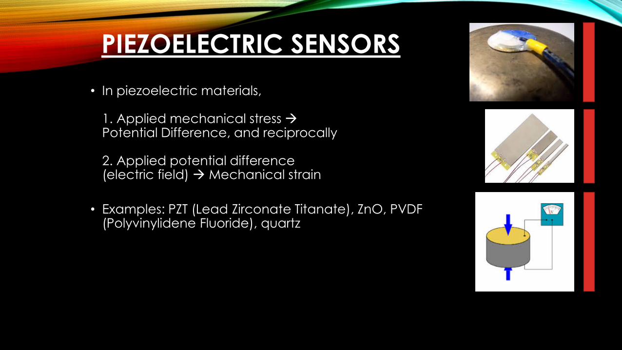
• In piezoelectric materials,
1. Applied mechanical stress Potential Difference, and reciprocally
2. Applied potential difference (electric field) Mechanical strain
• Examples: PZT (Lead Zirconate Titanate), ZnO, PVDF (Polyvinylidene Fluoride), quartz

• Applications- Micromachining, Actuation mechanism, Sensing mechanical stress, force, etc.
• Limitations:- Can be used for dynamic conditions only, not static conditions- Not used in standard microelectronics technology

PIEZO RESISTIVE SENSORS
• Physical phenomena, Strain change in the resistance
• In metal strain gauges, change in resistance is due to change in its dimensions; resistivity remains constant.
• In semiconductor piezo-resistors, both dimensions of resistor and resistivity change.
• Sensitivity of semiconductor type sensors > that of metallic type.

• Applications: Pressure sensors, accelerometers
• Advantages:1. Compatible with micro-fabrication processes2. Ease of signal processing3. High sensitivity4. High linearity
• Limitations:1. Temperature sensitive2. Susceptible to junction leakage3. Performance depends on proper packaging

MEMS ACCELEROMETERS
• MEMS accelerometers measure acceleration typically in units of gees (g)
• Airbag crash-sensing accelerometers, measuring vibrations, satellite navigation, etc.

• Working Principle:Measurement of the relative displacement of a proof mass as a result of a change in acceleration of the body.
F
Sensitivity, S = Δx/a = M/k
x(t), v(t),
a(t)

• All the three approaches, viz. 1. piezo-electric, 2. piezo-resistive, and 3. capacitive sensing methods used for realization.

• When the frame is subjected to acceleration perpendicular to its plane there will be a stress induced in the beams to accelerate the seismic mass. The change in length because of the stress changes the resistance of the resistors, which can be converted to voltage.

• For any resistor
R= ρL/Wt
W is width, t is thickness.
• Sensitivity = ΔR/εR. ε is strain.
• For metals it is of the range 2 to 5, but for semiconductor where ΔR changes with resistivity along with change in physical dimensions it is of order 100 to 200 depending on doping density.

• The acceleration of the base is directly
proportional to the displacement of the spring.
• The spring elongates to provide
acceleration to the proof mass.
• Displacement can be known by
measuring the change in capacitance.

• C= εA/d
• If the displacement is x, then
• C1= εA/(d+x), C2= εA/(d-x)
• By measuring C1- C2 we can get x.
• Now for the proof mass, kx=ma.
• a is obtained once x is known.

GYROSCOPE
• Senses inertial angular motion about its input axis without external reference.
• Two major categories –
a) for providing inertial reference
b) for providing angular rate information
A host of physical laws were utilized to develop operational gyros. The typical physical laws are
1. Gyros based on conservation of angular momentum of a spinning rotor
2. Gyros based on Coriolis effect on a vibrating mass.
3. Optical gyros based on Sagnac effect.

SPINNING ROTOR GYRO
CONSTRUCTION
It has three gimbals and the rotor is spun at high velocity and connected to the inner most gimbal. Depending upon the application, its clamped on to different platforms.
Its applications are quite limited now, owing to better quality ones in the market.

DYNAMICALLY TUNED GYROSCOPE
- These are available at a reasonable price.
- Considerably less investment in materials, machinery, processes and man power when compared to the other usual sensors such as the floated or ring-laser gyroscopes.
- DTG is a two degree-of-freedom sensor that measures angular rates

PRINCIPLEBased on an inertia rotor suspended by a universal joint with flexure pivots.
The flexure spring stiffness is independent of spin rate.
Dynamic inertia (from the gyroscopic reaction effect) from the gimbal provides negative
spring stiffness proportional to the square of the spin speed .Therefore, at a particular
speed, called the tuning speed, the two moments cancel each other, freeing the rotor
from torque, a necessary condition for an ideal gyroscope.

CONSTRUCTIONParts should be modelled with very low tolerance.
PARTS ASPECTS
Case Medium-strength steel, should be magnetically shielded
Torquer coils Enameled copper wire
Pick-off cores 0.1mm Fe-Si blades cut by EDM; reference surfaces grinded to
enhance the final positioning precision; 4 variable reluctance
transformers placed at 90° to each other
Synchronous
hysteresis motor
Responsible for keeping the gyroscope shaft to spin at constant
spinspeed
Shaft Medium-strength steel
Inertial rotor Pure iron piece for magnetic properties

Pick-off set
Shaft
The ball bearings should be manufactured with
high precision. The lubricating oil should have low
vapor pressure.
The magnetic rings are responsible for the
magnetic field, in which the torquer coils are
placed to interact with, leading to the control
torques.
The most difficult item to be done is the flexible
joint. The recommended material is high strength
steel with low internal strains, to resist the
acceleration loads and to minimize deformations
after machining.
The gimbal is made of high-strength steel to
satisfy the repeated straining.

WORKINGThere are two pairs of pick-offs in
two perpendicular directions,
each consisting of a primary and
secondary coil. The outputs of
these pick-offs are differentially
connected. Whenever rotation
happens, the air gap for one pick-
off increases while the other
decreases, producing a net
output from the paired pick-offs
proportional to the rotation.

APPLICATIONS
1. Active Rollover Protection in
Vehicles: It detects impending rollover
and selectively applies breaks to
resist.
2. Used widely in tactical missiles and
other aerospace applications for
guidance and navigation purposes.

RING LASER GYROSCOPE
It is an optical gyro.
Has very limited number of
moving parts
One among the most
commonly used gyroscopes
finding applications in a
wide variety of fields.
Based on Sagnac effect
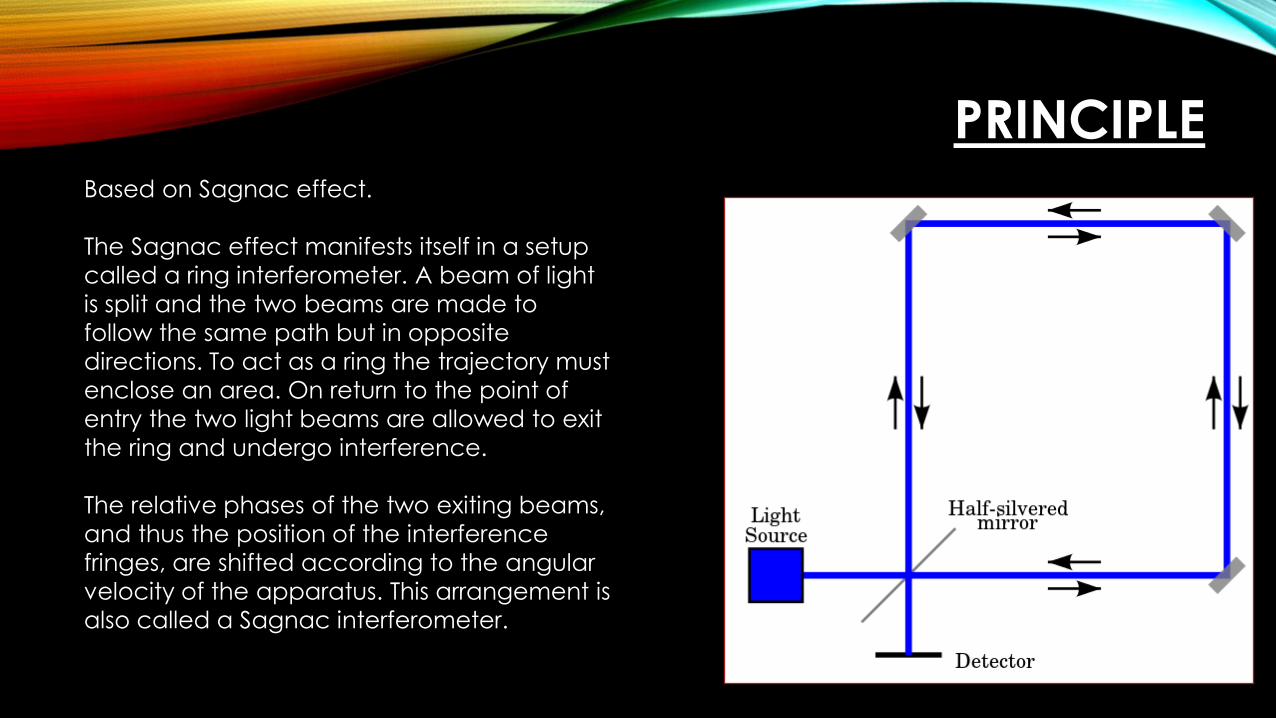
PRINCIPLEBased on Sagnac effect.
The Sagnac effect manifests itself in a setup
called a ring interferometer. A beam of light
is split and the two beams are made to
follow the same path but in opposite
directions. To act as a ring the trajectory must
enclose an area. On return to the point of
entry the two light beams are allowed to exit
the ring and undergo interference.
The relative phases of the two exiting beams,
and thus the position of the interference
fringes, are shifted according to the angular
velocity of the apparatus. This arrangement is
also called a Sagnac interferometer.


CONSTRUCTION
PARTS ASPECTS
Basic structure Carefully machined; glass ceramic material with very
low coefficient of thermal expansion is used
Mirrors 3 mirrors are fixed to the block; they are multidielectric
coated and have high reflectivity; substrate roughness
of around 1 or 2 angstrom
Amplifying
medium
The amplifying medium (to compensate for the loses an
amplifier ring is used) is a 10:1 mixture of He and Ne
excited by a DC discharge.

WORKING
At the output of the ring interferometer, the CW and
CCW waves interfere to produce a fringe pattern
which shifts if a rotation rate is applied along an axis
perpendicular to the plane of the beam path.
The two CW and CCW light rays experience a relative
phase difference proportional to the rotation rate, O.
This is based on the fact that with respect to inertial
space, the two counter-propagating light waves take
different times to complete a trip around a rotating
closed path. We obtain a fringe pattern which is
detected to get the appropriate output.
I am Mister Sagnac
Effect!


APPLICATIONS
It finds major application in almost all of the major
aircrafts and missiles such as Airbus 320, Agni III,
Boeing 757, Boeing 777, the Indian made HAL
Tejas and even on the International Space Station.
It has high sensivity. It is also used in ships.
MEMS GYRO
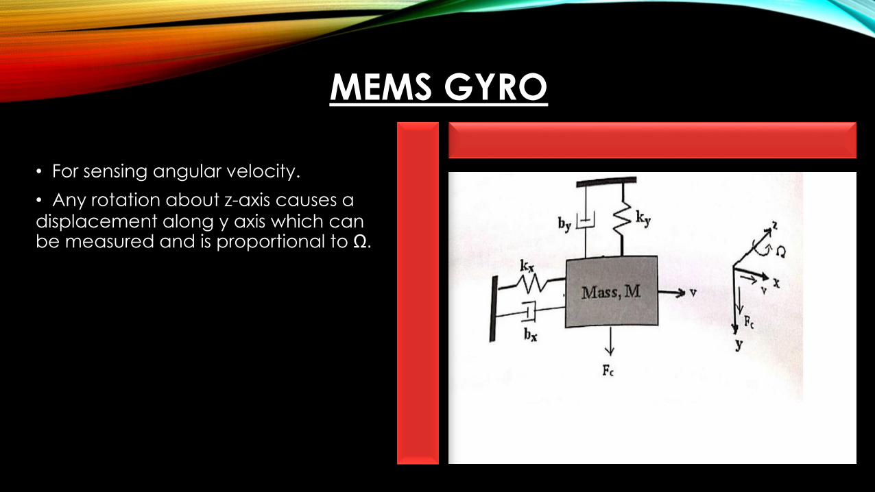
• For sensing angular velocity.
• Any rotation about z-axis causes a displacement along y axis which can be measured and is proportional to Ω.

• Consider the tuning fork gyroscope.
• Fc = 2xMxVxΩ.
• The mass plates A & B are driven into vibration by electrostatic actuat-ion. When there is a rotation along z-axis, The Coriolis force acts along y-axis and its amplitude along y-axisis given byAy = 2(Ax)(Qy)Ω/(wy).Ax is amplitude along x-axis,Qy is quality factorwy is angular frequency along y-axisand wx is made equal to wy.