navedtra 14075
TRANSCRIPT

DISTRIBUTION STATEMENT A: Approved for public release; distribution is unlimited.
NONRESIDENT
TRAINING COURSE
April 1987
Engineman 1 & C
NAVEDTRA 14075
NOTICE
Page 6-2 must be printed on a COLOR printer

DISTRIBUTION STATEMENT A: Approved for public release; distribution is unlimited.
Although the words “he,” “him,” and “his” are used sparingly in this course to enhance communication, they are not intended to be gender driven or to affront or discriminate against anyone.

COMMANDING OFFICERNETPDTC
6490 SAUFLEY FIELD RDPENSACOLA, FL 32509-5237
ERRATA #1 12 Mar 1991
Specific Instructions and Errata forTraining Manual and
Nonresident Training Course
ENGINEMAN 1 & C
1. No attempt has been made to issue corrections for errors in typing,punctuation, etc., that do not affect your ability to answer the question orquestions.
2. To receive credit for deleted questions, show this errata to your localcourse administrator (ESO/scorer). The local course administrator isdirected to correct the course and the answer key by indicating the questiondeleted.
3. Assignment Booklet
Delete the following questions, and leave the corresponding spaces blankon the answer sheets:
Questions Questions
3-69 8-46
7-32 9-21
7-40 9-22
7-53
Make the following changes:
Question
2-23
3-35
4-35
5-42
Change
In the question, line 2, change the words"ship-to-ship" "to ship-to-shop."
In the question, line 4, delete the word"chief."
In choice 1, change the word "pressure"to read "presence" and delete the word"the" before "oil."
In choice 2, change the word "tapped" toread "tappet."

8-4 In the question, line 1, change the words"an air" to read "A."
In the instructions foranswering questions9-55 through 9-58
Change figure numbers "9-4" and"9-5" to read "7-4" and "7-5."
4. Textbook, Engineman 1 & C
Make the following changes:
Page Column Par.
2-4 Right 2
8-14 Right 1
9-13 Left 3
Change
Change "feed" to "feet."
Change "chapter 63" to"chapter 631."
Delete repeat sentencestarting from "a few lightsending to switchboards."

i
PREFACE By enrolling in this self-study course, you have demonstrated a desire to improve yourself and the Navy. Remember, however, this self-study course is only one part of the total Navy training program. Practical experience, schools, selected reading, and your desire to succeed are also necessary to successfully round out a fully meaningful training program. COURSE OVERVIEW: In completing this nonresident training course, you will demonstrate a knowledge of the subject matter by correctly answering questions on the following: maintenance of engines, reduction gears, air-conditioning equipment, and additional auxiliary machinery; the performance and efficiency of an engine; engineering casualty control; engineering records and reports; and ship inspections and trials.
THE COURSE: This self-study course is organized into subject matter areas, each containing learning objectives to help you determine what you should learn along with text and illustrations to help you understand the information. The subject matter reflects day-to-day requirements and experiences of personnel in the rating or skill area. It also reflects guidance provided by Enlisted Community Managers (ECMs) and other senior personnel, technical references, instructions, etc., and either the occupational or naval standards, which are listed in the Manual of Navy Enlisted Manpower Personnel Classifications and Occupational Standards, NAVPERS 18068. THE QUESTIONS: The questions that appear in this course are designed to help you understand the material in the text. VALUE: In completing this course, you will improve your military and professional knowledge. Importantly, it can also help you study for the Navy-wide advancement in rate examination. If you are studying and discover a reference in the text to another publication for further information, look it up.
1983 Edition Prepared by ENC Kenneth L. Butts
Published by NAVAL EDUCATION AND TRAINING
PROFESSIONAL DEVELOPMENT AND TECHNOLOGY CENTER
NAVSUP Logistics Tracking Number 0504-LP-026-7410

ii
Sailor’s Creed
“I am a United States Sailor. I will support and defend the Constitution of the United States of America and I will obey the orders of those appointed over me. I represent the fighting spirit of the Navy and those who have gone before me to defend freedom and democracy around the world. I proudly serve my country’s Navy combat team with honor, courage and commitment. I am committed to excellence and the fair treatment of all.”

CONTENTS
iii
CHAPTER Page
1. Introduction . . . . . . . . . . . . . . . . . . . . . . . . . . . . . . . . . . . . . . . . . 1-1
2. Administration, Supervision, and Training. . . . . . . . . . . . . . . 2-1
3. Engine Maintenance . . . . . . . . . . . . . . . . . . . . . . . . . . . . . . . . . . 3-1
4. Reduction Gears and Related Equipment . . . . . . . . . . . . . . . . 4-1
5. Engine Performance and Efficiency. . . . . . . . . . . . . . . . . . . . . 5-1
6. Refrigeration and Air Conditioning . . . . . . . . . . . . . . . . . . . . . 6-1
7. Auxiliary Machinery . . . . . . . . . . . . . . . . . . . . . . . . . . . . . . . . . . 7-1
8. Environmental Pollution . . . . . . . . . . . . . . . . . . . . . . . . . . . . . . 8-1
9. Engineering Casualty Control . . . . . . . . . . . . . . . . . . . . . . . . . . 9-1
INDEX . . . . . . . . . . . . . . . . . . . . . . . . . . . . . . . . . . . . . . . . . . . . . . . . . . . . I-1
Nonresident Career Course follows Index

CREDITS
The illustrations indicated below are included in this edition of Engineman1 & C through the courtesy of the designated sources. Permission to use theseillustrations is gratefully acknowledged. Permission to reproduce illustrationsand other materials in this publication should be obtained from the source.
Sources: Figures:
Bacharach Industrial InstrumentCompany
3-1, 3-2, 3-3
iv

v
INSTRUCTIONS FOR TAKING THE COURSE
ASSIGNMENTS The text pages that you are to study are listed at the beginning of each assignment. Study these pages carefully before attempting to answer the questions. Pay close attention to tables and illustrations and read the learning objectives. The learning objectives state what you should be able to do after studying the material. Answering the questions correctly helps you accomplish the objectives. SELECTING YOUR ANSWERS Read each question carefully, then select the BEST answer. You may refer freely to the text. The answers must be the result of your own work and decisions. You are prohibited from referring to or copying the answers of others and from giving answers to anyone else taking the course. SUBMITTING YOUR ASSIGNMENTS To have your assignments graded, you must be enrolled in the course with the Nonresident Training Course Administration Branch at the Naval Education and Training Professional Development and Technology Center (NETPDTC). Following enrollment, there are two ways of having your assignments graded: (1) use the Internet to submit your assignments as you complete them, or (2) send all the assignments at one time by mail to NETPDTC. Grading on the Internet: Advantages to Internet grading are: • you may submit your answers as soon as
you complete an assignment, and • you get your results faster; usually by the
next working day (approximately 24 hours). In addition to receiving grade results for each assignment, you will receive course completion confirmation once you have completed all the
assignments. To submit your assignment answers via the Internet, go to:
http://courses.cnet.navy.mil
Grading by Mail: When you submit answer sheets by mail, send all of your assignments at one time. Do NOT submit individual answer sheets for grading. Mail all of your assignments in an envelope, which you either provide yourself or obtain from your nearest Educational Services Officer (ESO). Submit answer sheets to:
COMMANDING OFFICER NETPDTC N331 6490 SAUFLEY FIELD ROAD PENSACOLA FL 32559-5000
Answer Sheets: All courses include one “scannable” answer sheet for each assignment. These answer sheets are preprinted with your SSN, name, assignment number, and course number. Explanations for completing the answer sheets are on the answer sheet. Do not use answer sheet reproductions: Use only the original answer sheets that we provide—reproductions will not work with our scanning equipment and cannot be processed. Follow the instructions for marking your answers on the answer sheet. Be sure that blocks 1, 2, and 3 are filled in correctly. This information is necessary for your course to be properly processed and for you to receive credit for your work. COMPLETION TIME Courses must be completed within 12 months from the date of enrollment. This includes time required to resubmit failed assignments.

vi
PASS/FAIL ASSIGNMENT PROCEDURES If your overall course score is 3.2 or higher, you will pass the course and will not be required to resubmit assignments. Once your assignments have been graded you will receive course completion confirmation. If you receive less than a 3.2 on any assignment and your overall course score is below 3.2, you will be given the opportunity to resubmit failed assignments. You may resubmit failed assignments only once. Internet students will receive notification when they have failed an assignment--they may then resubmit failed assignments on the web site. Internet students may view and print results for failed assignments from the web site. Students who submit by mail will receive a failing result letter and a new answer sheet for resubmission of each failed assignment. COMPLETION CONFIRMATION After successfully completing this course, you will receive a letter of completion. ERRATA Errata are used to correct minor errors or delete obsolete information in a course. Errata may also be used to provide instructions to the student. If a course has an errata, it will be included as the first page(s) after the front cover. Errata for all courses can be accessed and viewed/downloaded at: http://www.advancement.cnet.navy.mil STUDENT FEEDBACK QUESTIONS We value your suggestions, questions, and criticisms on our courses. If you would like to communicate with us regarding this course, we encourage you, if possible, to use e-mail. If you write or fax, please use a copy of the Student Comment form that follows this page.
For subject matter questions: E-mail: [email protected] Phone: Comm: (850) 452-1001, Ext. 1826 DSN: 922-1001, Ext. 1826 FAX: (850) 452-1370 (Do not fax answer sheets.) Address: COMMANDING OFFICER NETPDTC N314 6490 SAUFLEY FIELD ROAD PENSACOLA FL 32509-5237 For enrollment, shipping, grading, or completion letter questions E-mail: [email protected] Phone: Toll Free: 877-264-8583 Comm: (850) 452-1511/1181/1859 DSN: 922-1511/1181/1859 FAX: (850) 452-1370 (Do not fax answer sheets.) Address: COMMANDING OFFICER NETPDTC N331 6490 SAUFLEY FIELD ROAD PENSACOLA FL 32559-5000 NAVAL RESERVE RETIREMENT CREDIT
If you are a member of the Naval Reserve, you may earn retirement points for successfully completing this course, if authorized under current directives governing retirement of Naval Reserve personnel. For Naval Reserve retire-ment, this course is evaluated at 22 points. Points will be credited in units as follows:
Unit 1: 12 points upon satisfactory
completion of assignments 1 through 5. Unit 2: 10 points upon satisfactory
completion of assignments 6 through 11.
(Refer to Administrative Procedures for Naval Reservists on Inactive Duty, BUPERSINST 1001.39, for more information about retirement points.)

vii
Student Comments Course Title: Engineman 1 & C NAVEDTRA: 14075 Date: We need some information about you: Rate/Rank and Name: SSN: Command/Unit Street Address: City: State/FPO: Zip Your comments, suggestions, etc.: Privacy Act Statement: Under authority of Title 5, USC 301, information regarding your military status is requested in processing your comments and in preparing a reply. This information will not be divulged without written authorization to anyone other than those within DOD for official use in determining performance. NETPDTC 1550/41 (Rev 4-00


CHAPTER 1
lNTRODUCTlON
At this stage in your naval career, you are wellaware that training on a continuous basis is essen-tial if you are to reach your desired goals, andif the mission of the Navy is to be successfullyaccomplished. The purpose of this manual is toserve as one of many sources of information asyou continue your training to become proficientin the tasks you will be required to perform at theE-6 and E-7 levels of your rating. A knowledgeof the information in this manual, combined withthe everyday practical experience, should help youlearn to perform assigned tasks and accept greaterresponsibilities.
RESPONSIBILITIES AND REWARDS
As you attain each higher promotional levelin your rating, you, as well as the Navy, benefit.The fact that you are using this training manualindicates that you have found personal satisfac-tion in developing your skills, increasing yourknowledge, and getting ahead in your chosencareer. The Navy has benefited, and will continueto do so as you become more valuable as atechnical specialist in your rating and as a per-son who can supervise and train others, thusmaking far reaching and long lasting contributionsto the success of the Navy.
In large measure, the extent of your contribu-tion to the Navy depends upon your willingnessand ability to accept increasing responsibilities asyou advance. When you assumed the duties of anEN3, the Navy rewarded you with an increase inpay and responsibility, a responsibility not onlyfor yourself but for the work of others. With eachadvancement, you accept an increasing respon-sibility in military matters and in matters relating
to the occupational requirements of theEngineman rating.
You will find that your responsibilities formilitary leadership are about the same as thoseof petty officers in other ratings, since everypetty officer is a military person as well as atechnical specialist. Your responsibilities fortechnical leadership are specific to your rating andare directly related to the nature of your work.Operating and maintaining the machinery andequipment for which an Engineman is responsi-ble is a job of vital importance. It is a teamworkjob which requires that special kind of supervisoryability that can only be developed by personnelwho have a high degree of technical competenceand a deep sense of personal responsibility.
Certain practical details that relate to yourresponsibilities for administration, supervision,and training are discussed in subsequent chaptersof this training manual. At this point, let’s con-sider some of the broader aspects of your everincreasing responsibilities for military andtechnical leadership.
YOUR RESPONSIBILITIES WILL EX-TEND BOTH UPWARD AND DOWNWARD.Officers and Supervisors will expect you to carryout their orders. Enlisted personnel will expect youto translate the general orders given by officersinto detailed, practical on-the-job language thatcan be understood and followed even by relativelyinexperienced personnel. In dealing with yourjuniors, it is up to you to see that they performtheir work properly. At the same time, you mustbe able to explain to officers any important needsor problems pertaining to the enlisted personnel.
YOU WILL HAVE REGULAR AND CON-TINUING RESPONSIBILITIES FOR TRAIN-ING. Even if you are fortunate enough to have
1-1
a highly skilled and well trained group, you willstill find that additional training is necessary. Forexample, you will always be responsible fortraining lower rated personnel to perform theirassigned tasks. Occasionally, some of your bestworkers may be transferred and replaced by in-experienced or poorly trained personnel. Also,some particular job may call for skills that noneof your personnel have. These and similar prob-lems will require you to be a training specialistwho can train individuals and groups in theeffective execution of assigned tasks.
YOU WILL HAVE INCREASINGRESPONSIBILITIES FOR WORKING WITHOTHERS. You will find that many of your plansand decisions affect a large number of people,some of whom are not in your division and someof whom are not even in the engineering depart-ment. It becomes increasingly important,therefore, to understand the duties and respon-sibilities of personnel in other ratings. Everypetty officer in the Navy is a technical specialistin his/her own field. Learn as much as you canabout the work of other ratings, and plan yourown work so that it will fit in with the overall mis-sion of the organization.
AS YOUR RESPONSIBILITIES IN-CREASE, YOUR ABILITY TO COM-MUNICATE CLEARLY AND EFFECTIVELYMUST ALSO INCREASE. The basic require-ment for effective communication is a knowledgeof your own language. Use correct language inspeaking and in writing. Remember that the basicfunction of all communication is understanding.To lead, supervise, and train others, you must beable to speak and write in such a way that otherscan understand exactly what you mean. You mustbe able to convey information accurately,simply, and clearly.
A second requirement for effective com-munication in the Navy is a sound knowledge ofthe Navy way of saying things. Some Navy termshave been standardized for the purpose of ensur-ing efficient communication. When a situationcalls for the use of standard Navy terminology,use it.
Still another requirement for effective com-munication is precision in the use of technicalterms. Command of the technical language of the
Engineman rating will enable you to exchangeideas with other personnel of the same rating. Per-sonnel who do not understand the precise mean-ing of terms used in connection with the work oftheir own rating are at a disadvantage when theytry to read official publications relating to theirwork. They are also at a great disadvantage whentaking written examinations for advancement.Although it is always important to use technicalterms correctly, it is particularly important whenyou are dealing with lower rated personnel. Slop-piness in the use of technical terms may beextremely confusing and frustrating to an inex-perienced person.
YOU WILL HAVE INCREASED RESPON-SIBILITIES FOR KEEPING UP WITH NEWDEVELOPMENTS. Practically everything in theNavy—policies, procedures, equipment, publica-tions, systems—is subject to change and develop-ment. As an EN1, and even more as an ENC, youmust keep yourself informed about all changesand new developments that might affect yourrating or your work.
Some changes will be called directly to yourattention; others you will have to look for. Tryto develop a special kind of alertness for new in-formation. Keep up to date on all sources oftechnical information. Information on sources ofprimary concern to the Engineman is given laterin this chapter.
As you prepare to assume increased respon-sibilities at a higher level, you need to be familiarwith (1) the military requirements and occupa-tional standards given in the Navy EnlistedManpower and Personnel Classifications andOccupational Standards, NAVPERS 18068 (withchanges); (2) the Personnel AdvancementRequirement (PAR), NAVPERS 1414/4; (3)appropriate rate training manuals; and (4) anyother material that may be required or recom-mended in the most current edition of theBibliography for Advancement ExaminationStudy, NAVEDTRA 10052. These materials andtheir use are discussed more thoroughly in MilitaryRequirements for Petty Officers 1 & C, NAVED-TRA 10057 (current edition), and Engineman3 & 2, NAVEDTRA 10541 (current edition).Other sources of information will be describedlater in this chapter.
ENGINEMAN 1 & C
1-2

Chapter 1—INTRODUCTION
THE ENGINEMAN—YOUR JOB
Since you first became a rated person you havemastered basic skills, became familiar with muchof the terminology applicable to internal combus-tion engines and other equipment, and learned toanswer many of the technical questions asked bylower rated personnel. Along with this increasein knowledge, you have gradually assumed greaterresponsibilities. The rate for which you are nowpreparing demands more knowledge and skill, awillingness to assume greater responsibility, andthe ability to lead people.
As an EN1 or ENC, you must be familiar withall the functions of the engineering departmentand be proficient in a wide variety of tasks. Yourduties will include using proper procedures fortroubleshooting, maintenance and repair, plan-ning, organizing, and carrying out the workinvolved in these procedures. You will maintainrecords and submit reports; you will supervise thestowage of supplies and repair parts; and you willtake an active part in the training of lower ratedpersonnel. In brief, you will be a technicalspecialist and a military leader.
MILITARY DUTIES ANDRESPONSIBILITIES
Information related to the militaryrequirements for advancement is included in train-ing manuals specifically prepared to cover suchrequirements. These manuals are listed anddescribed briefly later in this chapter.
TECHNICAL DUTIES ANDRESPONSIBILITIES
A petty officer must become a technicalspecialist in his/her rating. Technical duties whichan Engineman must learn to perform efficientlyinclude:
1. Operating internal combustion engines andauxiliary engineroom machinery.
2. Maintaining internal combustion enginesand related accessories and equipment.
3. Performing overhaul and repair work oninternal combustion engines, using establishedprocedures for disassembly, replacement, andreassembly.
4. Conducting routine tests and inspectionsof all engineroom machinery.
5. Operating and making repairs to auxiliaryboilers and to refrigeration, air conditioning, anddistilling systems.
6. Using lathes and other machine shopequipment.
7. Using measuring instruments needed inengine overhaul, such as micrometers, feelergages, and inside and outside calipers.
8. Reading accurately such instruments asthermometers, pressure gages, and pressureindicators.
Probably you can already do many of thesejobs. Others you will have to learn from addi-tional practical experience and through study.Although you will be learning many new jobs asan EN1, and especially as a ENC, you will be con-cerned principally with directing and observingthe work of personnel assigned to you. You willbe responsible for their performance and theirtraining in all of the jobs required of anEngineman.
In addition to the duties already mentioned,you will compile necessary data for the prepara-tion of engineering reports and records. It will beyour duty to make frequent tours of assignedspaces, and to inspect equipment for properoperation. You will check the auxiliary watch forperformance of duty in accordance with standingorders. You will be responsible for the use of thecorrect operating procedure for all equipmentunder your jurisdiction. You will be accountablefor daily routine inspections, tests, and reportson all equipment that require daily maintenanceand testing.
You may be held responsible to the divisionofficer for the proper setting and standing of allwatches during your duty period. You may berequired to post the daily watch list in theengineroom and may be responsible for instruct-ing and training watchstanders in their duties.
You will instruct lower rated personnel in thecorrect procedures to be used for casualtiesinvolving the engineroom. It will be yourresponsibility to see that personnel under your
1-3

supervision learn about the capabilities and limita-tions of the equipment with which they work, andthe procedures to follow should casualties occur.
Safety is a responsibility of all Navy person-nel. As an EN1 or ENC, you will instruct yourpersonnel in shipboard safety precautions, par-ticularly those that are applicable to your division,and will ensure that copies of these precautionsare posted in conspicuous places. Most impor-tantly, you will watch for careless methods ofwork—the frequent source of accidents. You willbe expected to set a good example for followingsafety practices. The example you will set will havea great influence on your people and other per-sonnel. You will watch for and report all unsafeconditions.
To successfully perform your duties, youshould know the duties performed in other divi-sions, and how the various shops can help youget a job done. While it is true that manymaintenance and repair jobs occurring in yourown division can be properly handled from startto finish without the aid of any outside rating,other jobs may be more extensive and may requirespecial skills or equipment not available withinyour division. Although you and the personnelunder your supervision may be able to do the bulkof the work, certain portions of a job may requirethe skill of an Electrician’s Mate, a Machinist’sMate, a Machinery Repairman, a HullMaintenance Technician, or people in otherratings. Therefore, you must know what equip-ment is used by other ratings in the engineeringdepartment, and what kind of work can be donewith that equipment. Familiarize yourself with thework performed and equipment used in other divi-sions by observing them at work and by talkingto leading petty officers in other ratings. Thereis no excuse for using unskilled personnel and un-satisfactory procedures when the skill of otherratings and the equipment they use are alreadyavailable.
WATCH DUTIES ANDRESPONSIBILITIES
As a first class or chief petty officer aboardship, you may be required to assist the divisionofficer in organizing, supervising, and instructingother personnel in their military duties as well as
in their specialties. This duty includes assisting inthe assignment of watch stations and other duties.
Every watch in the engineering department isa vital part of the ship’s maintenance and opera-tion program. The engineer officer is responsiblefor the operation and maintenance of the mainengines and auxiliary machinery. However, theEN1s or ENCs and the personnel they superviseon the various watches actually do most of thework. Therefore, it is very important that the pettyofficers in charge learn and understand theextent of their responsibility to the engineerofficer.
Engineering Officerof the Watch
The following excerpts from chapter 10 ofNavy Regulations describe some of the duties ofthe officer of the engineroom watch:
“Status, Authority, and Responsibil-ity. The engineering officer of the watchis the officer on watch in charge of themain propulsion plant of the ship, and ofthe associated auxiliaries. He shall beresponsible for the safe and proper opera-tion of such units, and for the perform-ance of the duties prescribed in theseregulations and by other competentauthority.”
“Directing and Relieving theEngineering Officer of the Watch. Theengineer officer, or in his absence, themain propulsion assistant may direct theengineering officer of the watch con-cerning the duties of the watch, or mayassume charge of the watch, and shall doso should it, in his judgment, benecessary.”
“Relation with the Officer of theDeck. The engineering officer of thewatch shall ensure that all orders re-ceived from the officer of the deck arepromptly and properly executed. He shallnot permit the main engines to be turnedexcept as authorized or ordered by theofficer of the deck.”
ENGINEMAN 1 & C
1-4

Chapter 1—INTRODUCTION
“Reports by the Engineering Officerof the Watch. The engineering officer ofthe watch shall report promptly to theofficer of the deck and the engineerofficer any actual or probable derange-ment of machinery, boilers, or auxiliarieswhich may affect the proper operation ofthe ship.”
“Reports to the Engineering Officerof the Watch. The engineering officer ofthe watch shall be promptly informed ofany engineering work or change indisposition of machinery which mayaffect the proper operation of the plantor endanger personnel, or which is re-quired for entry in the record of hiswatch.”
“Inspection and Operation ofMachinery. The engineering officer of thewatch shall cause frequent inspections tobe made of the engines, boilers, and theirauxiliaries; and shall ensure that pre-scribed tests, methods of operation, andinstructions pertaining to the safety of per-sonnel and material are strictly observed.”
“Records and Logs. The engineeringofficer of the watch shall ensure that theengineering log, engineer’s bell book, andprescribed operating records are properlykept. On being relieved, he shall sign theengineering log and the engineer’s bellbook for that watch.”
Engineering DepartmentDuty Officer
In ships not underway, the commandingofficer may authorize the standing of a day’sduty in lieu of the continuous watch of theengineering officer of the watch. When author-ized, the duties of the engineering officer, of thewatch are assigned in port to the engineeringdepartment duty officer. However, when not atthe station of the engineering officer of the watch,the duty officer must always be ready for dutythe moment he/she is summoned or notified thathis/her presence is required. The engineering
department duty officer, assigned by the engineerofficer, must be a qualified engineering officer ofthe watch. On some ships, chief petty officers maybe assigned as the engineering department dutyofficer.
In the temporary absence of the engineerofficer, the duties of the engineer officer may beperformed by the engineering department dutyofficer. If the engineer officer is on board, theduty officer reports the condition of the depart-ment to him/her prior to the eight o’clock reports.In the absence of the engineer officer, the dutyofficer makes the eight o’clock reports for thedepartment to the executive officer (or commandduty officer).
The engineering duty officer, in addition tosuch other duties as may be properly assigned tohim/her, is responsible for:
1. The alertness and proper performance ofall personnel of the engineering watches.
2. The safe and economical operation of allengineering machinery and systems in use.
3. The elimination of fire and floodinghazards and the prevention of sabotage.
4. The security of all engineering spaces. Inorder to determine the actual conditions thatexist in the engineering space and to evaluate theperformance of watch personnel, the duty officermust make frequent inspections of the engineer-ing spaces.
5. The proper maintenance of all machineryoperating logs, and for writing and signing theengineering log for the period he/she is on duty.
The engineering department duty officermakes reports in the same manner as the engineer-ing officer of the watch, except that when actingin place of the engineer officer, he/she is respon-sible for making the reports required of thatofficer. Engineering watch supervisors and theduty petty officers of the engineering divisionsreport to the duty officer during the performanceof their duties.
A chief petty officer who is a qualifiedengineroom watch supervisor underway may beassigned a watch as the engineering departmentduty chief petty officer to assist the engineeringdepartment duty officer. The duty chief pettyofficer is normally assigned duty for the same
1-5

ENGINEMAN 1 & C
period as the duty office, and reports to thatofficer.
and that the prescribed pressure is maintained inthe firemain.
Standing Watches
As a watchstander, you will be the “eyes” ofthe engineering department. You will be respon-sible for the orderly appearance and cleanlinessof your assigned station. Prior to standing watch,you should thoroughly inspect all existing condi-tions, such as the operating condition ofmachinery and firefighting equipment. Youshould also check your assigned area for leaks andpotential fire hazards. If a casualty occurs, youshould take immediate steps to control it, as wellas promptly notify the proper authority.
Except in emergencies, the engineroom aux-iliary watch does not make any changes such asstopping, starting, or shifting ship’s servicegenerators without first notifying the Electrician’sMate and the petty officer in charge of the watch.
A watch going off duty will not be consideredrelieved until the floor plates are wiped, theengineroom is clean, all operating logs and recordsare correct, and information concerning the statusof the machinery in operation, orders, specialorders, and non-completed orders have been givento the relief.
While on watch, you should strictly observeall operating instructions, regulations, andsafety precautions. You should never leave yourstation unless you have permission from properauthority to do so, or are properly relieved. Youshould promptly execute all standing or specialorders. When relieved, you should pass on to therelieving watch all information concerning existingconditions and special orders.
There are several watches that you may standor for which you may be responsible. The stationsand duties of some of the watches commonlystood by Enginemen are discussed in the follow-ing paragraphs.
COLD-IRON WATCHES.—Under certainprescribed conditions (such as when a ship movesalongside a repair ship or tender, or into a navalshipyard, and is receiving power from theseactivities) a security and fire watch is usually setby each division. This security watch is commonlyknown as a cold-iron watch. Each cold-iron watchmakes frequent inspections of the assigned areaand checks for fire hazards, flooding, or otherunusual conditions throughout the area. The cold-iron watch keeps bilges reasonably free of waterin accordance with applicable instructions. Hourlyreports on existing conditions are made to theofficer of the deck.
ENGINEROOM AUXILIARY WATCH.—Auxiliary watches are maintained underway andin port to supply light, power, steam, and otherservices. The engineroom auxiliary watch main-tained in port includes a petty officer in chargeand one or more Firemen. The petty officer incharge is responsible for seeing that an efficientand economical watch is being stood. Allmachinery not in operation must be checked tosee that it has been properly secured.
All unusual conditions are immediatelyreported to the officer of the deck and to theengineering duty officer, so that the proper divi-sion or department can be notified to take thenecessary corrective measures. When welding orburning is to be performed in the area, the cold-iron watch checks to see that a fire watch isstationed.
The petty officer in charge of the auxiliarywatch is responsible for the proper operation ofthe ship’s service generator and associatedmachinery; however, the operation of the elec-trical equipment is the responsibility of an Elec-trician’s Mate. The petty officer in charge checksto see that all operating machinery is lubricatedas prescribed by the operating instructions.He/she makes sure that the fire and flushingpumps are inspected for satisfactory operation
If the ship is in drydock, the watch must checkall sea valves, after working hours, to see that thevalves are secured or blanked off. The watch mustmake sure that oil or water is not being pumpedinto the drydock and that weights such as fuel oil,feedwater, or potable water are not shiftedwithout permission of the engineer officer.
DUTY ASSIGNMENTS
As an Engineman, you will be assigned dutyaboard various types of ships, ranging from air-craft carriers to the smallest of river patrol boats.You will also be assigned shore duty. Your specific
1-6
Chapter 1—INTRODUCTION
duties will depend on the type and size of ship orstation to which you will be assigned.
Aboard an aircraft carrier or a cruiser, youmay be assigned to the “A” division. As amember of the “A” gang, you will be responsi-ble for a wide variety of tasks including theoperation, maintenance and repair of internalcombustion engines, and the operation andmaintenance of auxiliary, refrigeration, and airconditioning equipment.
On diesel-driven ships, you may be assignedto the “M” division or the “A” division. Yourresponsibility will vary depending on the size ofthe ship. You may have charge of one of theengineering spaces or the “A” gang and, on somesmall ships, you may act as the “M” divisionofficer.
On a repair ship or tender, you may be as-signed to the repair department. As an EN1 orENC, you may be in charge of one of the repairshops such as the engine overhaul shop or thegovernor and fuel injector shop, or you may bein charge of one of the repair gangs. You mayalso be selected to attend Diesel Inspector’s schooland become a Navy diesel engine inspector.
Duty at most shore stations will depend onyour training and your field of specialization. Youmay also be assigned as an instructor either at oneof the Engineman schools or at a recruit trainingstation, or a canvasser recruiter. To qualify forinstructor duty, you must successfully completea course in instructor training.
As an Engineman, you may perform duty atthe Naval Education and Training Program andDevelopment Center, Pensacola, FL. Personnelassigned to this activity are involved in either thepreparation of service-wide examinations foradvancement or the preparation and revision ofrate training manuals and other training materials.
SCOPE OF THISTRAINING MANUAL
Before studying any book, it is a good ideato know the purpose and the scope of that book.Here are some things you should know about thistraining manual:
It is designed to give you information onthe occupational qualifications for advancementto EN1 and ENC.
It must be satisfactorily completed beforeyou can advance to EN1 or ENC, whether youare in the Regular Navy or in the Naval Reserve.
It is NOT designed to give you informa-tion on the military requirements for advancementto PO1 or CPO. Rate training manuals that arespecially prepared to give information on themilitary requirements are discussed in the sectionof this chapter that deals with sources ofinformation.
It is NOT designed to give you informa-tion that is related primarily to the qualificationsfor advancement to EN3 and EN2. Such infor-mation is given in Engineman 3 & 2, NAVED-TRA 10541 (current edition).
The occupational qualifications that wereused as a guide in the preparation of this train-ing manual were those promulgated in the NavyEnlisted Manpower and Personnel Classificationsand Occupational Standards, NAVPERS 18068-D(1981). Therefore, changes in the Enginemanqualifications that may have occurred after theD edition became effective may not be reflectedin the information given in this training manual.
This training manual includes informationthat is related to both the knowledge and the Oc-cupational Standards for advancement to EN1and ENC. However, no training manual can takethe place of actual on-the-job experience fordeveloping skill in the practical factors. This train-ing manual can help you understand some of thewhys and wherefores, but you must combineknowledge with practical experience before youcan develop the required skills. The Personnel Ad-vancement Requirement, NAVPERS 1414/4,should be utilized in conjunction with this trainingmanual whenever possible.
Subsequent chapters in this trainingmanual deal with the technical subject matter ofthe Engineman rating. Before studying thesechapters, study the table of contents andnote the arrangement of information. You willfind it helpful to get an overall view of theorganization of this training manual before youstart to study it.
1-7

ENGINEMAN 1 & C
SOURCES OF INFORMATION
It is very important for you to have an exten-sive knowledge of the references to consult fordetailed, authoritative, up-to-date information onall subjects related to the military requirementsand to the occupational qualifications of theEngineman rating.
Center. Each revised edition is identified by aletter following the NAVEDTRA number. Whenusing this publication, be SURE you have themost recent edition.
Some of the publications discussed here aresubject to change or revision from time to time—some at regular intervals, others as the need arises.When using any publication that is subject tochange or revision, be sure you have the latest edi-tion. When using any publication that is kept cur-rent by means of changes, be sure you have a copyin which all official changes have been entered.
In NAVEDTRA 10052, the required andrecommended references are listed by pay gradelevel. It is important to remember that you areresponsible for all references used at lower levels,as well as those listed for the pay grade to whichyou are seeking advancement.
NAVAL EDUCATION ANDTRAINING (NAVEDTRA)PUBLICATIONS
Rate training manuals that are marked withan asterisk (*) in NAVEDTRA 10052 are MAN-DATORY at the indicated levels. A mandatorytraining manual may be completed by (1)passing the appropriate Enlisted CorrespondenceCourse based on the mandatory training manual,(2) passing locally prepared tests based on the in-formation given in the mandatory trainingmanual, or (3) in some cases, successfullygraduating from an appropriate Navy school.
Originally, training manuals were developedby the Chief of Naval Training and carried thedesignation NAVTRA followed by a number. In1973, the Naval Education and Training Produc-tion Development Center (NETPDC) came di-rectly under the command of the Chief of NavalEducation and Training (CNET). Trainingmaterials published by NETPDC after the abovedate are designated NAVEDTRA in lieu of NAV-TRA; however, the numbers remain as originallyassigned for most publications. The designatorsof publications printed prior to 1973 will bechanged as each publication is revised.
It is important to note that all references,whether mandatory or recommended, listed inNAVEDTRA 10052, may be expected to be usedas source material for the written examinationsat the appropriate levels. In addition, referenceslisted in a rate training manual may also be usedas source material for examination questions.
Rate Training Manuals
The naval training publications described hereinclude some which are absolutely essential foranyone seeking advancement and some which,although not essential, are extremely helpful.
Most rate training manuals are written for thespecific purpose of helping personnel prepare foradvancement. Some manuals are general in natureand are intended for use by more than one rating;others (such as this one) are specific to a particularrating.
NAVEDTRA 10052
The Bibliography for Advancement Examina-tion Study, NAVEDTRA 10052 is a very impor-tant publication for anyone preparing foradvancement. This publication lists required andrecommended rate training manuals and otherreference material to be used by personnelworking for advancement. NAVEDTRA 10052is revised and issued once each year by the NavalEducation Training and Program Development
Rate training manuals are revised from timeto time to bring them up to date. The revision ofa rate training manual is identified by a letterfollowing the NAVEDTRA number. You can tellwhether or not a rate training manual you areusing is the latest edition by checking the NAVED-TRA number and the letter following it in themost recent edition of the List of TrainingManuals and Correspondence Courses, NAVED-TRA 10061 (revised).
There are three rate training manuals that arespecially prepared to present information on the
1-8

Chapter 1—INTRODUCTION
military requirements for advancement. Thesemanuals are:
Basic Military Requirements, NAVEDTRA10054 (current edition)
Military Requirements for Petty Officer3 & 2, NAVEDTRA 10056 (current edition)
Military Requirements for Petty OfficerI & C, NAVEDTRA 10057 (current edition)
Each of the military requirements manuals ismandatory at the indicated pay grade levels. Inaddition to giving information on the militaryrequirements, these three books give a good dealof useful information on the enlisted rating struc-ture; on how to prepare for advancement; on howto supervise, train, and lead other people; and onhow to meet increasing responsibilities as you ad-vance in rating.
Some of the rate training manuals that maybe useful to you when you are preparing to meetthe occupational qualifications for advancementare discussed briefly in the following paragraphs.
Tools and Their Uses, NAVEDTRA 10085(current edition), contains a good deal of usefulinformation on the care and use of all types ofhandtools and portable power tools commonlyused in the Navy.
Blueprint Reading and Sketching, NAVED-TRA 10077 (current edition), chapters 1 through4 and chapter 7, recommended reading in prepar-ing for advancement to EN2. The remainder ofthe training manual contains additional informa-tion that may be of value to you as you preparefor advancement to EN1 and ENC.
Mathematics, Vol. 1, NAVEDTRA 10069(current edition), and Mathematics, Vol. 2,NAVEDTRA 10071 (current edition), may behelpful if you need to brush up on yourmathematics. Volume 1 contains basic informa-tion that is needed for using formulas and formaking simple computations. Volume 2 containsmore advanced information than you will needfor most purposes. However, occasionally, youmay find the information in this book to behelpful.
Engineman 3 & 2, NAVEDTRA 10541 (cur-rent edition), must be satisfactorily completed foradvancement to EN3 and EN2. If you have metthis requirement by satisfactorily completingearlier editions of training manuals prepared forEnginemen, you should at least become familiarwith Engineman 3 & 2, NAVEDTRA 10541 (cur-rent edition). Much of the information given inthis edition of Engineman I & C is based on theassumption that you are familiar with the con-tents of Engineman 3 & 2, NAVEDTRA 10541(current edition).
Rate training manuals prepared for otherGroup VII (Engineering and Hull) ratings areoften a useful source of information. Referenceto these training manuals will broaden yourknowledge of the duties and skills of other per-sonnel in the engineering department. The train-ing manuals prepared for Machinist’s Mates,Boiler Technicians, and Machinery Repairmen arelikely to be of particular interest to you.
For a complete listing of rate training manuals,consult the List of Training Manuals and Cor-respondence Courses, NAVEDTRA 10061 (latestrevision).
Correspondence Courses
Most rate training manuals and officer textsare used as the basis for correspondence courses.Credit for the completion of a mandatory train-ing manual is earned by passing the cor-respondence course that is based on that trainingmanual. You will find it helpful to take other cor-respondence courses, as well as those that arebased on mandatory training manuals. A cor-respondence course helps you to master the in-formation given in the training manual or text.It also gives you a good idea of how much youhave learned.
NAVSEA PUBLICATIONS
A number of publications issued by the NavalSea Systems Command (NAVSEA) will be of in-terest to you. While you do not need to knoweverything that is given in the publications men-tioned here, you should have a general idea ofwhere to find information in NAVSEApublications.
1-9

ENGINEMAN 1 & C
The Naval Ships’ Technical Manual is a basicdoctrine publication of NAVSEA. To allow theship to distribute copies to the working spaceswhere information is required, chapters are nowissued as separate paper-bound volumes. Chaptersare kept up to date by means of yearly revisions.Chapters are reviewed less frequently where yearlyrevisions are not necessary. In chapters whereintra-year changes are required, either an intra-year edition or a NAVSEA Notice is distributedas a temporary supplement for use pending issueof the new edition of the chapter.
You will find chapters in Naval Ships’Technical Manual of particular importance to theEngineman referenced in this training manual.For a list of all chapters in the manual, seeappendix A, chapter 001.
The Deck Plate is a monthly publication whichcontains interesting and useful information on allaspects of shipboard engineering. This magazineis particularly useful because it presents informa-tion which supplements and clarifies informationcontained in the Naval Ships’ Technical Manualand because it presents information on new equip-ment, policies, and procedures.
Manufacturers’ technical manuals that are fur-nished with most machinery units and many typesof equipment are valuable sources of information
on operation, maintenance, and repair ofmachinery and equipment. The manufacturers’technical manuals for internal combustion enginesand associated equipment are usually givenNAVSEA numbers.
TRAINING FILMS
Training films which are available to navalpersonnel are a valuable source of supplementaryinformation on many technical subjects. Filmsthat may be of interest to you are listed in theDepartment of the Navy Catalog of AudiovisualProduction Products, OPNAVINST 3 157.1.
When selecting a film, note its date of issuein the film catalog. As you know, proceduressometimes change rapidly. Thus some filmsbecome obsolete rapidly. If a film is obsoleteonly in part, it may sometimes be shown effec-tively if before or during its showing you carefullypoint out to trainees the procedures that havechanged. When you plan to show a film to trainpersonnel, take a look at it in advance if possibleso that you may spot material that may havebecome obsolete, then verify current proceduresby looking them up in the appropriate sourcesbefore showing the film.
1-10

CHAPTER 2
ADMINISTRATION, SUPERVISION,AND TRAINING
The higher you go in the Navy, the moreresponsibility you will have for administration,supervision, and training. This chapter dealsbriefly with some of your administrative andsupervisory responsibilities and then takes up cer-tain aspects of your responsibility for trainingothers.
Although it is possible to consider administra-tion, supervision, and training as three separateareas of responsibility, it is important toremember that the three cannot be totallyseparated. Much of your work requires you to ad-minister, supervise, and train, all at the same time.For example, consider a pump overhaul job. Asan administrator, you will schedule the job, checkon the history of the pump, and see that therequired forms and reports are submitted.
As a supervisor, you will actually oversee thework and make sure it is done correctly. As atrainer, you will provide information and instruc-tion on repair parts, repair procedures andpolicies, safety precautions, and other matters.
These administrative, supervisory, and train-ing tasks have a direct relationship to the job athand—namely, the overhaul of the pump. But thepump overhaul job can’t even get started unlessa variety of administrative, supervisory, and train-ing functions are performed on a continuing basis.Materials, repair parts, and tools must beavailable when they are needed; jobs must bescheduled with due regard to the urgency of otherwork; records must be kept and reports must besubmitted; and personnel must be in a continuousstate of training so that they can assume increas-ingly important duties and responsibilities. Theonly way to keep things running smoothly is totake your administrative, supervisory, and train-ing responsibilities seriously.
ADMINISTRATION ANDSUPERVISION
As an Engineman, you will have ad-ministrative and supervisory responsibilities inconnection with engineroom and auxiliary opera-tions and with equipment maintenance and repair.
OPERATIONAL RESPONSIBILITIES
The engineering department administrativeorganization is set up to provide a means for theproper assignment of duties and for the propersupervision of personnel. However, no organiza-tion can run itself. Personnel—including you—are needed to see that all pertinent instructionsare carried out; that all machinery, equipment,and piping systems are operated in accordancewith good engineering practice; that operatinginstructions and safety precautions are posted bythe machinery and obeyed by all engineroompersonnel; that all watchstanders are properlysupervised; that records and reports are filled-incorrectly and submitted as required; and that theentire engineering plant is operated with max-imum reliability, efficiency, and safety.
In order for you to monitor and record yourplant’s status and performance, you need to knowwhich engineering records and reports for theadministration, maintenance, and repair of navalships are prescribed by directives from suchauthorities as the Type Commander, Naval ShipSystems Command (NAVSHIPS), and Chief ofNaval Operations (CNO). These records must beaccurate and up to date in accordance with cur-rent instructions.
As an EN3 and EN2, you have been primarilyconcerned with operating logs and similar records.As an EN1 or ENC, you will have new supervisory
2-1

ENGINEMAN 1 & C
duties which will require that you have a greaterknowledge of engineering paperwork and theassociated administrative procedures. Supervisoryduties and responsibilities require a knowledge ofengineering records as well as of such items asinspections, administrative procedures, training,preventive maintenance, and repair procedures.
Information on the most common engineer-ing records and reports is given in this chapter.These standard forms are prepared by the varioussystems commands and CNO. The forms are forissue to forces afloat and can be obtained asindicated in the Navy Stock List of Forms andPublications, NAVSUP 2002. Since these formsare revised as conditions warrant, personnel order-ing forms must be sure that the most currentforms are obtained. When complementary formsare necessary for local use, make certain that anexisting standard form will not serve the purposebefore having complementary forms prepared andprinted.
Legal Engineering Records
The Engineering Log and the Engineer’s BellBook are the only legal records compiled by theengineering department. The Engineering Log isa midnight-to-midnight record of the ship’sengineering department. The Engineer’s Bell Bookis a legal record of any order regarding changein the movement of the propellers.
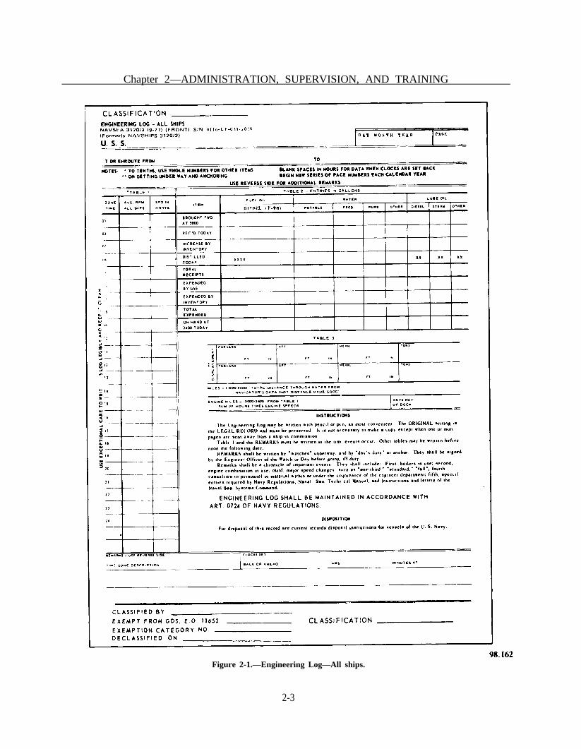
ENGINEERING LOG.—The EngineeringLog, NAVSEA 3120/2 (figure 2-1), and the LogContinuation Sheet, NAVSEA 3120/2A, areused to record important daily events and datapertaining to the engineering department and theoperation of the engineering plant. A table is pro-vided in the log for recording the hourly averagerpm (to the nearest tenth) of all shafts and theresultant speed, in knots. Additional tables andspaces are provided for recording the ship’s draftand displacement (upon getting underway andanchoring or mooring); the total engine milessteamed for the day and the distance traveledthrough water; the number of days out of dock;the amount of fuel, water, and lubricating oil onhand, received, and expended; the name of theship, the date, and the location or route of theship; and remarks chronicling important events.
Entries in the Engineering Log must be madein accordance with instructions given (1) on thelog sheet (NAVSEA 3120/2), (2) in chapter 10 ofU.S. Navy Regulations, (3) in Naval Ships’Technical Manual, chapter 9004, and (4) in direc-tives of the type commander.
Remarks written in the Engineering Log mustinclude (1) boilers in use, (2) engine combinationin use, (3) major speed changes (such as 1/3, 2/3,standard, and full), (4) all injuries to personneloccurring within the department, (5) casualtiesoccurring to material under the cognizance of theengineering department, and (6) such other mat-ters as may be specified by competent authority.Each entry must be a complete statement andemploy standard phraseology. The type com-mander’s directives contain other specificrequirements pertaining to the “remarks” sectionof Engineering Logs for ships of the type; theengineer officer must ensure compliance withthese directives.
The original Engineering Log, prepared neatlyand legibly in ink or pencil, is the legal record.The remarks should be prepared—and must besigned—by the engineering officer of the watch(EOOW) (underway) or the engineering depart-ment duty officer (in port). No erasures are per-mitted in the log. When a correction is deemednecessary, a single line is drawn through theoriginal entry so that the entry remains legible andthe correct entry is inserted in such a manner asto ensure clarity and legibility. Corrections,additions, or changes are made only by the per-son required to sign the log for the watch and areinitialed by him on the margin of the page.
The engineer officer verifies the accuracy andcompleteness of all entries and signs the logdaily. The commanding officer approves the logand signs the log on the last calendar day of eachmonth and on the date he relinquishes command.The engineer officer should require that the logsheets be submitted to him in sufficient time toallow him to check and sign them prior to noonof the first day following the date of the logsheet(s).
When the commanding officer (or engineerofficer) directs a change or addition to theEngineering Log, the person concerned mustcomply unless he believes the proposed change oraddition to be incorrect; in this event the
2-2
Chapter 2—ADMINISTRATION, SUPERVISION, AND TRAINING
Figure 2-1.—Engineering Log—All ships.
2-3

ENGINEMAN 1 & C
commanding officer (or engineer officer) enterssuch remarks over his signature as he deems ap-propriate. After the log has been signed by thecommanding officer, no change is permittedwithout his permission or direction.
Completed Engineering Log sheets are filedin a post-type binder. Pages of the log arenumbered consecutively with a new series of pagenumbers commencing with the first day of eachcalendar year.
ENGINEER’S BELL BOOK.—TheEngineer’s Bell Book, NAVSEA 3120/ 1 (figure2-2), is a record of all bells, signals, and otherorders received by the throttleman regardingmovement of the ship’s propellers. Entries aremade in the Bell Book by the throttleman (or anassistant) as soon as an order is received. Entriesmay be made by an assistant when the ship isentering or leaving port, or engaging in anymaneuver which is likely to involve numerous orrapid speed changes. This procedure allows thethrottleman to devote his undivided attention toanswering the signals.
The Bell Book is maintained in the followingmanner:
1. A separate bell sheet is used for each shafteach day, except where more than one shaft iscontrolled by the same throttle station, in whichcase the same bell sheet is used to record the ordersfor all shafts controlled by the station. All sheetsfor the same date are filed together as a singlerecord.
2. The time of receipt of the order is recordedin column number 1 (figure 2-2).
3. The order received is recorded in columnnumber 2. Minor speed changes (generally re-ceived via revolution telegraph) are recorded byentering the number of rpm ordered. Major speedchanges (normally received via engine ordertelegraph) are recorded using the followingsymbols:
1 / 3 — ahead 1/3 speed2/3 — ahead 2/3 speedI — ahead standard speedII — ahead full speedIII — ahead flank speedZ — stopB1/3 — back 1/3 speed
2-4
B2/3 — back 2/3 speedBF — back full speedBEM — back emergency speed
4. The number of revolutions correspondingto the major speed change ordered is entered incolumn 3. (NOTE: When the order received isrecorded as rpm in column 2 (minor speedchanges), no entry is made in column 3.)
5. The shaft revolution counter reading (totalrpm) at the time of the speed change is recordedin column 4. The shaft revolution counterreading—as taken hourly on the hour, whileunderway—also is entered in column 4.
Ships and craft equipped with controllablereversible pitch propellers record in column 4 thepropeller pitch in feed and fractions of feet setin response to a signaled speed change, rather thanthe shaft revolution counter readings. The entriesfor astern pitch are preceded by the letter B. Eachhour on the hour, entries are made of counterreadings, thus facilitating the calculation of enginemiles steamed during those hours when thepropeller pitch remains constant at the last valueset in response to a signaled order.
Before going off watch, the EOOW signs theBell Book on the line following the last entry forhis watch and the next EOOW continues therecord immediately thereafter. In machineryspaces where an EOOW is not stationed, the bellsheet is signed by the watch supervisor.
The Bell Book is maintained by bridge per-sonnel in ships and craft equipped with con-trollable reversible pitch propellers, and in whichthe engines are directly controlled from the bridge.When control is shifted to the engineroom,however, the Bell Book is maintained by theengineroom personnel. The last entry made in theBell Book on the bridge indicates the time thatcontrol is shifted; and the first entry made in theBell Book in the engineroom indicates the timethat control is taken by the engineroom.Similarly, the last entry made by engineroom per-sonnel indicates when control is shifted to thebridge. When the Bell Book is maintained by thebridge personnel, it is signed by the officer of thedeck (OOD) in the same manner as prescribed forthe EOOW.
Alterations or erasures are not permitted inthe Bell Book. An incorrect entry is corrected by

Chapter 2—ADMINISTRATION, SUPERVISION, AND TRAINING
Figure 2-2.—Engineer’s Bell Book, NAVSEA 3120/1.
2-5

ENGINEMAN 1 & C
drawing a single line through the entry andrecording the correct entry on the following line.Deleted entries are initialed by the EOOW, theOOD, or the watch supervisor, as appropriate.
Operating Records and Reports
Engineering operating records are meant toensure regular inspection of operating machineryand to provide data for performance analysis.Operating records are not intended to replace fre-quent inspections of operating machinery bysupervisory personnel and are not to be trustedimplicitly to provide warning of impendingcasualties. Personnel who maintain operatingrecords must be properly indoctrinated. Theymust be trained to correctly obtain, interpret, andrecord data, and to report any abnormal condi-tions noted.
The type commander’s directives specifywhich engineering operating records will be main-tained and prescribe the forms to be used whenno standard record forms are provided. Theengineer officer may require additional operatingrecords when (all factors considered—includingthe burden of added paperwork) he deems themnecessary.
The operating records discussed in this chapterare generally retained on board for a period of2 years, after which time they may be destroyedin accordance with current disposal regulations.Completed records must be stowed where they willbe properly preserved, and in such a manner asto ensure that any one of the records can beeasily located.
D I E S E L E N G I N E O P E R A T I N GRECORD.—The Diesel Engine OperatingRecord-all Ships, NAVSEA 9231/2 (figures 2-3and 2-4), is a daily record maintained for eachoperating diesel engine. In ships with more thanone main engine in the same engineroom, aseparate record sheet is maintained for eachoperating engine.
The watch supervisor enters the remarks andsigns the record for his watch. The petty officerin charge of the engineroom or the seniorengineman checks the accuracy of the record andsigns the record in the space provided on the backof the record. Any unusual conditions noted in
2-6
the record are immediately reported to theengineer officer and the record is sent to theengineer officer for approval.
FUEL AND WATER ACCOUNTS.—Themaintenance of daily diesel fuel, lubricating oil,and water accounts is vital to the efficient opera-tion of the engineering department. Forms andprocedures necessary to account for and preservea limited supply of freshwater and fuel aregenerally prescribed by the type commanders.
Principally, the accounts inform the engineerofficer of the status of the ship’s liquid load andform the basis of reports submitted to higherauthority by the engineer officer.
It is fundamental to all naval operations thatthe ship and unit commanders know the exactamount of burnable fuel on hand. When com-puting the amount of burnable fuel on board,consider only the fuel in the service and storagetanks. All the fuel below the fuel suction line isto be considered not burnable.
FUEL AND WATER REPORTS.—The Fueland Water Report, NAVSEA 9255/9 (figures 2-5and 2-6), is a report submitted daily to the com-manding officer. This report indicates the amountof fuel oil and water on hand as of midnight, theprevious day. The Fuel and Water Report alsoincludes the previous day’s feed and potable waterperformance and results of water tests. Theoriginal and one copy are submitted to the OODin sufficient time for submission to the command-ing officer or command duty officer with the1200 reports. The copy is retained by the OOD.
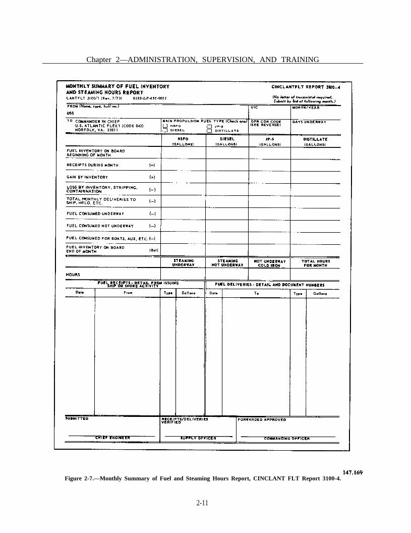
MONTHLY SUMMARY.—The MonthlySummary of Fuel Inventory and Steaming HoursReport is a comprehensive monthly report ofengineering data from which the operating effi-ciency and general performance of the ship’sengineering plant can be calculated (see figure2-7). Requirements for this report are containedin Fleet Commander Instructions. This report isprepared by the engineer officer and verified, asto fuel receipts, by the supply officer. Then, itis approved and forwarded by the commandingofficer directly to the fleet commander. A copyis retained on board in the files of the engineer-ing department. An additional copy of the reportmay be provided to the type commander.

Page
2-7
Fig
ure
2-3.
—D
iese
l E
ngin
e O
pera
ting
Rec
ord—
All
ship
s.

Page
2-8
Fig
ure
2-4.
—D
iese
l E
ngin
e O
pera
ting
Rec
ord—
All
ship
s (B
ack)
.

Chapter 2—ADMINISTRATION, SUPERVISION, AND TRAINING
Figure 2-5.—Fuel and Water Report (Front).
2-9

ENGINEMAN 1 & C
Figure 2-6.—Fuel and Water Report (Back).
2-10
Chapter 2—ADMINISTRATION, SUPERVISION, AND TRAINING
Figure 2-7.—Monthly Summary of Fuel and Steaming Hours Report, CINCLANT FLT Report 3100-4.
2-11

ENGINEMAN 1 & C
The Monthly Summary includes the ship’s fuelreceipts data, fuel consumption and steaminghours necessary to establish monthly financialobligations, and fuel requirements data for budgetjustification. It also generates managementreports for fuel receipts by operational and typecommanders. This report includes all fuel data asof 2400 hours of the last day of the month andmust be forwarded within 5 days of completionof the reporting month. Fleet CommanderInstructions contain detailed instructions for com-pleting the forms, as well as the definitions of theterms used.
In addition to data on fuel inventory, thereport contains space for fuel consumed under-way, fuel consumed not underway, and fuel con-sumed by boats. Space is also provided for totalsteaming hours broken down as underway and notunderway.
Most engineer officers prefer to compile thenecessary data for this summary on a daily basisrather than wait until the end of the month andmake computations from the various records. Themathematical accuracy of the computations mustbe observed when the report is being prepared toavoid the necessity of resubmitting a correctedform later.
Disposal of EngineeringRecords and Reports
Before any of the engineering departmentrecords are destroyed, the Disposal of Navy andMarine Corps Records, USN and USNS Vessels,SECNAVINST P5212.5 (revised), should bestudied. This publication informs ships of theNavy of the procedures used for disposing ofrecords. For each department aboard ship, theseinstructions list the permanent records which mustbe kept, and the temporary records which maybe disposed of in accordance with an establishedschedule.
Both the Engineering Log and Engineer’s BellBook must be preserved as permanent records onboard ship for a 3-year period unless they are re-quested by a Naval Court or Board, or by theNavy Department. In such case, copies (preferablyphotostatic) of such sheets or parts of theserecords that are sent away from the ship are
certified by the engineer officer as being truecopies for the ship’s files.
At regular intervals, such as each quarter, theparts of those records that are over 3 years oldare destroyed. When a ship that is less than 3 yearsold is decommissioned, the current books are re-tained. If a ship is scrapped, the current booksare forwarded to the nearest Naval RecordsManagement Center.
All reports forwarded to, and received from,NAVSEA or other superior command may bedestroyed when 2 years old, if they are no longerrequired.
Only those reports which are required or servea specified purpose should be maintained onboard ship. However, any report or record whichmay assist personnel in scheduling or makingrepairs and which will supply personnel withinformation which is not contained in publicationsor manuals should also be kept on board.
Trend and SpectrographicAnalysis
Two types of inspections and tests that can beused to “spot” impending trouble in an internalcombustion engine before it can seriously affectits operation are called trend and spectrographicanalyses. We will now discuss and explain theirimportance and use in detecting problems ininternal combustion engines.
ENGINE TREND ANALYSIS.—Preventivemaintenance receives a great deal of attentionfrom everyone in the field of diesel engine opera-tion, since the idea of letting an engine run as longas it will run and fixing it only after a breakdownoccurs is not only foolish, but extremely costly.On the other hand, it would be just as foolish tobe constantly tearing down an engine for inspec-tion. It is a known fact that vital parts of an enginelast longer and operate better if they are nottampered with unnecessarily. Therefore anattempt must be made to find a happy mediumbetween these two forms of maintenance.
One way is to determine the condition of anengine is by monitoring its operation. This is doneby regularly obtaining certain engine operatingdata and by studying, and analyzing, and com-paring it with previous data. This information isthen reduced to a form which all engineering
2-12

Chapter 2—ADMINISTRATION, SUPERVISION, AND TRAINING
personnel can interpret and, based on the findings,decide whether or not the engine needs to beoverhauled in order to ward off serious and costlydamage or just be temporarily shut down for somesimple maintenance.
The key to utilizing engine performance dataas a tool is to make graphs from the data whichshow at a glance the signs of impending distress.Analysis of this graphical display is commonlycalled trend analysis.
In order to get a good indication of the enginecondition, the following specific items arerecorded.
1. Cylinder compression pressures.2. Cylinder firing pressures.3. Fuel pump rack or governor power piston
position.4. Cylinder exhaust temperature.5. Crankcase vacuum.6. Lubricating oil pressure at engine inlet or
upper header.7. Manifold air or scavenging air pressure.
To produce meaningful graphs, all data mustbe plotted under the same conditions, and be ob-tained at some readily duplicated condition. It isnot important that the engine be under full loadat full speed when taking data, but it is impor-tant that all data be obtained under similar con-ditions. For example:
1. Always obtain data from generator sets at80% load and 100% speed.
2. Always obtain data from propulsionengines; for example, standard or full.
Data need not be plotted daily. In most cases,a set of readings should be plotted every 200 hoursof operation. In some cases it may be prudent torepeat a set of readings when a large change inoperating characteristics has apparently occurred.
The first step in preparing the graphs for trendanalysis is to collect the data. This is done byobserving and recording the above items with theengine operated at a selected type of condition fora sufficient time, prior to taking data, to allowpressures and temperatures to stabilize. (It can beassumed that conditions have stabilized when lubeoil and freshwater temperatures are within ± 5°of the normal operating temperatures.
These data are then plotted on 10 × 10 linesper inch graph paper as shown on the examples(figures 2-8 through 2-15). For convenience, thefirst points are located at zero time for an enginethat has just been overhauled or at the numberof hours on the engine since the last overhaul (0,400, 1000, 1600 hours, etc.). The first point forlube oil consumption occurs at 200 engine hours.This is done because it is easier to start with a fullengine sump and monitor the amount of oiladded each 200 hours to obtain the consumptionrate. Once the initial points have been plotted, allthat is required is to record and plot the sameinformation each 200 hours and observe the trendsthat develop. (NOTE: remember to always takedata under the same controlled conditions!)
A close look at the sample graphs will revealhow they can be used to determine engine condi-tion. For purposes of illustration, the ideal trendof each graphed value is shown for a hypotheticalengine. Unfortunately, the Navy does not havetoo many ideal engines so some samples ofproblem indications that may be expected are alsoincluded.
On figures 2-8 and 2-9, a high, average, andlow value is plotted for both firing and compres-sion pressures. Under normal conditions thesecurves will remain flat until the engine isapproaching the time of overhaul, then the curveswill start to fall off. The high and low firingpressures will remain at about ± 50 psi (100 psispread) from the average firing pressure for a well-balanced engine. If you look at figure 2-8 you cansee that a decided drop in firing pressure has oc-curred at 1600 hours (point A). This failure in thecompressing pressures indicates that the rings areeither sticking, broken, or beginning to wear; thatthe valves are not functioning properly; or thatthe liner is beginning to score or possibly that apiston has cracked. Remember that any changein a curve (beyond normal limits) indicates thatimmediate attention is required. At this point, itshould be pointed out that more than oneindicator will usually reveal the same distresssignal. Therefore, before any corrective action istaken, it is best to make a study of other curvesto deny or confirm the problem. In this case checkthe lube oil consumption, crankcase vacuum, andexhaust temperature curves. In figures 2-9, 2-10,and 2-15 the typical indications for this problem
2-13

ENGINEMAN 1 & C
Figure 2-8.— Firing Pressure Graph.
Figure 2-9.—Compression Pressure Graph.
2-14

Chapter 2—ADMINISTRATION, SUPERVISION, AND TRAINING
Figure 2-10.—Crankcase Vacuum Graph.
Figure 2-11.—Exhaust Temperature Graph.
2-15

ENGINEMAN 1 & C
Figure 2-12.—Lube Oil Pressure Graph.
Figure 2-13.—Scavenging Pressure Graph.
2-16

Chapter 2—ADMINISTRATION, SUPERVISION, AND TRAINING
Figure 2-14.—Rack Setting Graph.
Figure 2-15.—Lube Oil Consumption Graph.
2-17

are marked as point A. All indications point toa definite internal problem in one cylinder. Norise in lube oil consumption is indicated (point Aon figure 2-15) because a slightly worn set of ringsor liner probably would not cause a measurableincrease in lube oil consumption. The logs shouldnow be consulted to find the problem cylinder andinitiate appropriate repairs.
If only firing pressures and exhausttemperature are low, the fuel system should bechecked on the problem cylinder.
The crankcase vacuum graph (figure 2-10)indicates ring, piston, or liner condition. As longas everything is normal, this curve will also be flat.A cracked piston, worn rings, or liner will increaseblow-by, causing decreased crankcase vacuum. Ifcrankcase vacuum decreases with no change inother indicators, the crankcase scavenging systemshould be checked for proper operation. Anincrease in crankcase vacuum may be caused bya clogged intake screen.
The exhaust temperature graph (figure 2-11)indicates general cylinder conditions and enginebalance, although this item is not necessarily adefinite indication of trouble itself. Any abnor-mal temperature with no accompanying changein the various other indicators can usually beattributed to a faulty pyrometer. The pyrometerin question should then be carefully inspected andtested before any other inspections or adjustmentsare accomplished.
The lube oil pressure graph (figure 2-12)indicates the engine bearing condition, lube oilpump condition, piping conditions, by-pass reliefvalve conditions, etc. Lube oil pressure obtainedat the upper header of Fairbanks Morse opposedpiston engines is particularly useful in monitor-ing the condition of the internal portion of thelube oil system.
The manifold pressure graph (figure 2-13)indicates the condition of the scavenging system.Increasing air box pressures indicate portclogging, while reduced air box pressures indicatesome abnormality in the air intake systems,blower, or turbocharger. Both of these cases re-quire immediate attention.
The fuel rack or governor power piston posi-tion graph (figure 2-14) indicates the general con-dition of the fuel system. Increased rack settingsfor a given power output indicate fuel pump
deterioration or a decrease in engine combustionefficiency.
The lubrication oil consumption graph (figure2-15) is for the lubricating oil consumption ingallons per 200 hours operation. It should benoted that the values on this curve are initiallyvery high. They decrease and then remain nearlyconstant until the engine is approaching itsoverhaul time. The initial high consumption is dueto unseated piston rings. As rings become seated,the consumption will decrease to a normal valueand remain nearly constant until the rings or linersbegin to wear. Any significant increase in lube oilconsumption must be carefully evaluated to deter-mine if the oil is really being consumed in theengine or is being lost because of external leaks.Too many times an engine is assumed to be atfault when lube oil is really being lost due toleakage.
Review of figures 2-8 through 2-15 will alsoindicate other problems that are not discussed inthis text. Each sample problem is marked on thevarious graphs at the appropriate engine hours soa study of the samples can be made.
In conclusion, operational graphs show thecondition of the engine. They show what is hap-pening, what needs to be done, and what has tobe planned for in advance. The life expectancyof vital parts can be determined from these curves,and the parts can be renewed before they reachthe point of failure.
The trend analysis program must be followedclosely, especially during the initial period of theprogram when care must be taken to ensure thatthe data gathered are meaningful. However, if thecondition of any particular engine indicates thatan overhaul is required to maintain it operational,this should be accomplished at the earliest possi-ble time.
ENGINE LUBE OIL ANALYSIS.—Spectrometric oil analysis is another valuable toolwhich can be used to determine the extent ofaccelerated wear in internal combustion enginesand other machinery which use closed lube oil orhydraulic oil systems. By the use of spectrometricoil analysis, the accelerated wear in machinery canbe detected without disassembling the equipmentlong before there is any other indication of
ENGINEMAN 1 & C
2-18

Chapter 2—ADMINISTRATION, SUPERVISION, AND TRAINING
immediate trouble. As a result of this type ofanalysis, skilled maintenance personnel have beenable to pinpoint wear areas early, and to takecorrective and preventive maintenance actionduring an emergency or on a pre-planned basisas determined by the type of accelerated weardetected. By replacing worn out minor parts amajor failure can be prevented, and the require-ment for costly parts replacements of completeoverhaul of the equipment can be eliminated.
Ships shall maintain accurate records ofoperating hours since major overhauls, oilchanges, and samplings in order to provide thetesting facility with the information requested inthe sampling kit. (COMNAVSURFLANT usesthe services of the Charleston Naval Shipyard andCOMNAVSURFPAC uses IntermediateMaintenance Activities (IMA) for analyzing oilsamples from machinery employing closed lubeoil/hydraulic systems.) In addition, a record ofconditions found and repairs effected as a resultof inspections conducted following recom-mendations of the laboratory must also bemaintained.
When the shipyard or IMA laboratory receivesthe oil sample, a physical test and a spectrometricanalysis are performed. The physical test consistsof the following:
1. All samples are tested for fuel dilution, anda report is provided to all concerned by percentvolume as per requirements of ASTM D92057.
2. All samples are tested for solids bycentrifuge to show the amount of suspendedparticles separately from precipitated solids. Thetest must differentiate between those fine particlessuspended by the active compounds in the oil andthose that can settle out of the oil spontaneouslyto give a ratio of colloidal/precipitated solids.
3. Allowable “use limits” are tested andrecorded.
When the physical test is completed theshipyard/IMAs should make a spectrometricanalysis of each used oil sample, then record andreport to all concerned the concentrations of the
Element Concentration In
Standard Reference Specimen Standard Deviation(Range in PPM) (Maximum in PPM)
3- 9 1.510 - 19 220 - 49 350 - 99 5
100 - 199 8200 - 500 15
Figure 2-16.—Element Concentrations.
following elements in parts per million (ppm). (Seefigure 2-16.)
Iron (Fe) Nickel (Ni) *Sodium (Na)Lead (Pb) Silver (Ag) Phosphorus (P)Copper (Cu) Tin (Sn) Zinc (Zn)Chromium (Cr) Silicon (Si) Calcium (Ca)Aluminum (Al) Boron (B) Barium (Ba)
*Only when evidence of water is present.
Testing will be done for all the above elements.
The sensitivity and reliability of the equipmentused for the test will be such that the standarddeviation obtained in the analysis for eachspecified element must not exceed the appropriatevalue shown in figure 2-16.
Additional information on trend analysis andoil spectrometric analysis is contained in COM-NAVSURFLANTINST 9000.1 or COMNAV-SURFPACINST 4700.1A.
MAINTENANCE AND REPAIRRESPONSIBILITIES
In order to fulfill your maintenance and repairresponsibilities along with your administrative andsupervisory responsibilities you must plan yourwork ahead of time.
You must determine all the work that mustbe done and prepare a schedule to ensure that itis done. You must also keep your schedule flexi-ble enough to allow unexpected maintenance and
2-19

ENGINEMAN 1 & C
repair work to be done whenever the need for suchwork arises.
Review the Maintenance and MaterialManagement (3-M) Manual, OPNAVINST4790.4, it will make your planning and schedul-ing considerably easier.
Materials and Repair Parts
The responsibility for maintaining adequatestocks of engineroom repair parts and repairmaterials belongs at least as much to you as it doesto the supply department. The duties of the supplyofficer are to procure, receive, stow, issue, andaccount for the support of the ship. However, thesupply officer is not the prime user of repair partsand repair materials; the initiative for maintain-ing adequate stocks of repair materials, parts, andequipment must come from the personnel who aregoing to use such items. Namely You!
Basic information on supply matters is givenin Military Requirements for PO 3 & 2, NAVED-TRA 10056 (current edition), Military Re-quirements for PO 1 & C, NAVEDTRA 10057(current edition), and OPNAVINST 4790.4,volume II.
Identification of RepairParts and Materials
Identification of repair parts and materials isnot usually a great problem when you are deal-ing with familiar equipment on your own ship;but it may present problems when you are doingrepair work for other ships, as you would ifassigned to the machine shop on a repair ship ortender.
The materials and repair parts to be used arespecified for many repair jobs but not for all.When materials or parts are not identified in theinstructions accompanying a job, you will eitherhave to use your own judgment or do researchto find out just what material or part should beused. When you must make the decision yourself,select materials on the basis of the service condi-tions they must withstand. Operating pressure andoperating temperature are primary considerationsin selecting materials and parts for mostengineroom repair work.
The fact that materials and repair parts arenot specified in the instructions accompanying ajob does not mean that you are free to use yourown judgment in selecting parts and materials toaccomplish a job. Instead, it usually means thatyou must know where to look for information onthe type of material or repair parts needed, thenlocate and requisition them in order to completethe assigned job.
There are several shipboard sources of infor-mation that will be useful to you in identifyingthe equipment and/or the repair parts needed.They include the Coordinated ShipboardAllowance List (COSAL); nameplates on theequipment; manufacturer’s technical manuals;and ships’ plans, blueprints, and other drawings.
COORDINATED SHIPBOARD ALLOW-ANCE LIST (COSAL).—The COSAL isboth a technical and a supply document preparedfor an individual ship. It lists the equipment orcomponents required for the ship’s operation; therepair parts and special tools required, theoverhaul and repair equipment, and themiscellaneous portable items necessary for thecare and upkeep of the ship.
For your purpose, the COSAL is the basicsource of information on repair parts andmaterials needed for a job. A COSAL gives youinformation on such items as the noun name ofa system (engine, pump, ejector, etc.), themanufacturer’s name and the I.D. number(General Motors Corporation #3255), thetechnical manual number for the system, themanufacturer’s drawing numbers, and theAllowance Parts List (APL) numbers for relatedsystems (governor’s, starters, transmissions, etc.).In addition, COSAL provides specific informa-tion about National Stock numbers (NSNs), unitsof issue, costs, and the number of items needed.It may also include lists of part numbers andFederal Stock Numbers (FSNs) for crossoverchecks.
To request materials and repair parts from thesupply department aboard ship, you must fill outand submit a NAVSUP Form 1250, a single itemconsumption/management document. If the itemis not stocked aboard ship, the supply departmentwill requisition the material from a supply activity,using the identifying information that you havegiven on the NAVSUP Form 1250. However, if
2-20

Chapter 2—ADMINISTRATION, SUPERVISION, AND TRAINING
all the information you have available is amanufacturer’s part number, then you must alsofill out and submit, along with the NAVSUPForm 1250, a DD-1348-6 Form, NON-NSN REQ-UISITION. For information on how to fill outthese supply forms, review Military Requirementsfor PO 3 & 2, volume II of OPNAVINST 4790.4,or ask your ship’s supply personnel for assistance.
Whenever you find it necessary to requestmaterials or repair parts, remember two things:
1. If at all possible, find the correct NSN foreach item requested. All materials now in thesupply system have been assigned an NSN, andyou should be able to locate them by using theCOSAL and the other sources of informationavailable to you such as the following:
a. NAMEPLATES on equipment supplyinformation regarding the characteristics of theequipment. Nameplate data seldom, if ever,include the exact materials required for repairs;however, the information given on thecharacteristics of the equipment and on pressureand temperature limitations may provide usefulclues for the selection of materials.
b. MANUFACTURERS’ TECHNICALMANUALS are furnished with all machinery andequipment aboard ship. Materials and repair partsare sometimes described in the text of thesetechnical manuals; more commonly, however,details of materials and parts are given on thedrawings. Manufacturers’ catalogs of repair partsare also furnished with some shipboard equip-ment; when available, these catalogs are a valuablesource of information on repair parts andmaterials.
c. SHIPS’ PLANS, BLUEPRINTS, andOTHER DRAWINGS available on board ship areexcellent sources of information on materials andparts to be used in making various kinds ofrepairs. Many of these plans and blueprints arefurnished in the regular large sizes; but lately,microfilm is being used increasingly for thesedrawings. Information obtained from plans,blueprints, and other drawings should always bechecked against the information given on theship’s COSAL to be sure that any changes madesince the original installation have been noted onthe drawings.
2. Work informally with the supply depart-ment personnel who are actually responsible foridentifying and requesting material. You have thetechnical knowledge, and you know what youneed. If you cannot find the correct stock number,however, your job is to give enough standard iden-tification information, such as manufacturer partnumbers, and Allowance Parts List/ComponentIdentification Description (APL/CID) numbers,so that supply personnel on board ship or ashorecan identify the item you want. Experiencedsupply personnel are familiar with identificationpublications and can help you to locate the cor-rect stock numbers and other important identi-fying information.
SHIP EQUIPMENT CONFIGURATIONACCOUNTING SYSTEM (SECAS).—When thestructure or composition of either the ship or aparticular system or equipment on board a shipis modified, this modification must bedocumented. This action will ensure proper ac-counting of configuration changes, and will helpimprove supply and maintenance supporttechnical manuals, PMS coverage, updatedCOSAL, etc., to your ship. SECAS is thedesignated system responsible for maintaining theconfiguration status reported by your ship.
Although the responsibility for identifying andreporting these changes rests at all levels of thecommand, the work center supervisor is respon-sible for ensuring that the proper documentationis completed and processed as described in volumeII of OPNAVINST 4790.4.
OPNAV Form 4790/CK, Ship’s Configura-tion Change Form, is used to report configura-tion changes at the individual equipment level.
SHIP-TO-SHOP WORK.—Many repair jobsare designated by the ship or approved by therepair activity as “ship-to-shop” jobs. In this typeof job, the ship’s force does a large part of therepair work. For example, the repair or renewalof a damaged pump shaft might well be writtenup as a ship-to-shop job. The ship’s force willdisassemble the pump and remove the shaft. Thenthe shaft and any necessary blueprints or technicalmanuals are delivered to the designated shop ofthe repair activity. After the shaft has beenrepaired, or a new one has been made, it is
2-21

ENGINEMAN 1 & C
picked up and brought back to the ship by theship’s force. The pump is reassembled, inspected,and tested by the ship’s force to make sure thatit is operating satisfactorily.
An important thing to remember is that whilethe repair facility is responsible for ensuring thatits personnel repair or manufacture this shaft tothe manufacturer’s specifications, perform alltests required by Quality Assurance (QA), and fillout properly all the required forms, it is yourresponsibility to witness any test required by QA,to monitor the status of the job at all times, andto reassemble and test operate the equipmentproperly, so that the end results will produce areliable operating piece of equipment.
EQUIPMENT TESTS.—As an EN1 or ENC,you have the responsibility for scheduling and per-forming various tests on your equipment. Thepurpose of those tests is to determine how yourequipment is performing and if there are anyequipment malfunctions. These tests are per-formed at various times, such as (1) before goingto the shipyard for overhaul, (2) after post deploy-ment, (3) during a tender availability, or (4) asrequired by PMS. The tests are performed by theship’s force, IMA personnel, shipyard personnel,or by an inspection team (such as the Board ofInspection and Survey (INSURV Board)).Detailed types of inspections are described inCOMNAVSURFLANT Inst. 9000.1 or COM-NAVSURFPAC Inst. 4700.1A.
Scheduling Work
Careful planning is required to keep up withall auxiliary maintenance and repair work in theenginerooms. You should already have in yourwork center the necessary items which can helpyou in scheduling your work. These items are (1)the Quarterly PMS Schedule, which is the visualdisplay of your work center’s PMS requirementsfor a specific 3-month period; (2) the weeklyschedule (taken from the quarterly schedule),which displays all your work center’s PMSschedule for completion in a given week; and (3)the Maintenance Data Collection Subsystem(MDCS) forms, such as the OPNAV 4790-2K,OPNAV 4790-2L, and OPNAV 4790-2Q. Ofthese, OPNAV Form 4790.2K is used to show
completion of specific PMS requirements; torequest repair of equipment or services fromIMAs or shipyards; or can be used to describeequipment malfunctions. OPNAV Form 4790/2Lis a supplemental form which you use to provideamplifying information relating to a maintenanceaction described on a corresponding 4790/2K. TheOPNAV 4790/2L may also be used to list: Multi-ple item serial numbers and locations for whichidentical maintenance requirements exist from anoutside activity; and Drawings and sketches.
OPNAV Form 4790/2Q is an automated workrequest produced by an IMA with computercapabilities. The “2Q” is produced from theoriginal 4790/2K which is in your Current ShipsMaintenance Project (CSMP) suspense file. Formore detailed information about these forms andschedules, and how to fill them out, review OP-NAVINST 4790.4, volumes I and II.
Some of the proven uses you should followwhen scheduling maintenance and repair work arelisted below:
1. Size up each job before you let anyone startworking on it. Check the applicable MaintenanceRequirement Cards (MRCs) so that you will knowexactly what needs to be done. Also, check allapplicable drawings and manufacturer’s technicalmanuals.
2. Check on materials before you start. Besure that all required materials are available beforeyour personnel start working on any job. Do notoverlook small items—nuts, bolts, washers, pack-ing and gasket materials, tools, measuring devices,and so forth. A good deal of labor can be savedby the simple process of checking on the availabil-ity of materials before a job is actually started.An inoperable piece of machinery may be useless,but it can become a nuisance and a safety hazardif it is spread around the engineroom in bits andpieces while you wait for the arrival of repair partsor materials.
3. Check the priority of the job and that ofall other work that needs to be done.
4. When assigning work, carefully considerthe capabilities and experience of your personnel.As a rule, the more complicated jobs should begiven to the more skilled and more experienced
2-22

Chapter 2—ADMINISTRATION, SUPERVISION, AND TRAINING
people. When possible, however, less experiencedpeople should be given difficult work to do undersupervision so that they may acquire skill in suchjobs.
Be sure that the person who is going to do ajob is given as much information as necessary.An experienced person may need only a drawingand a general statement concerning the nature ofthe job. A less experienced person is likely torequire additional instructions and, as a rule,closer supervision.
5. Keep track of the work as it is being done.In particular, check to be sure that propermaterials and parts are being used, that the jobis properly laid out or set up, that all tools andequipment are being used correctly, and that allsafety precautions are being observed.
6. After a job has been completed, make acareful inspection to be sure that everything hasbeen done correctly and that all final details havebeen taken care of. Check to be sure that allnecessary records and reports have been prepared.These job inspections serve at least two veryimportant purposes: first, they are needed to makesure that the work has been properly performed;and second, they provide for an evaluation of theskills and knowledge of the person who has donethe work. Do not overlook the training aspectsof a job inspection. When your inspection of acompleted job reveals any defects or flaws, be sureto explain what is wrong, why it is wrong, andhow to avoid similar mistakes in the future.
Estimating Work
You will often be required to estimate theamount of time, the number of personnel, andthe amount of material that will be required forspecific repair jobs. Actually, you are makingsome kind of estimate every time you plan andstart a repair job, as you consider such questionsas: How long will it take? Who can best do thejob? How many people will be needed? Are allnecessary materials available?
However, there is one important differencebetween the estimates you make for your own useand those that you make when your division
officer asks for estimates. When you give anestimate to someone in authority over you, youcannot tell how far up the line this informationwill go. It is possible that an estimate you giveto your division officer could ultimately affect theoperational schedule of the ship; it is essential,therefore, that such estimates be as accurate asyou can possibly make them.
Many of the factors that apply to the schedul-ing of all maintenance and repair work apply alsoto estimating the time that will be required fora particular repair job. You cannot make areasonable estimate until you have sized up thejob, checked on the availability of materials,checked on the availability of skilled personnel,and checked on the priority of the various jobsfor which you are responsible. In order to makean accurate estimate of the time required to com-plete a specific repair job, you must also consider(1) what part of the work must be done by othershops, and (2) what kinds of interruptions anddelays may occur. Although these factors are alsoimportant in the routine scheduling ofmaintenance and repair work, they are particu-larly important when estimates of time that mayaffect the operational schedule of the ship aremade.
If part of the job must be done by other shops,you must consider not only the time actuallyrequired by these shops but also time that maybe lost if one of them holds up your work, andthe time spent to transport the material betweenshops. Each shop should make a separateestimate, and the estimates should be combinedin order to obtain the final estimate. Do NOT at-tempt to estimate the time that will be requiredby other personnel. Attempting to estimate whatsomeone else can do is risky because you can’tpossibly have enough information to make an ac-curate estimate.
Consider all the interruptions that might causedelay, over and above the time required for thework itself. Such things as drills, inspections, fielddays, and working parties can have quite aneffect on the number of people who will beavailable to work on the job at any given time.
Estimating the number of personnel who willbe required for a certain repair job is, obviously,closely related to estimating time. You will haveto consider not only the nature of the job and thenumber of people available but also the maximum
2-23

ENGINEMAN 1 & C
number of people who can work EFFECTIVELYon a job or on part of the job at the same time.Doubling the number of personnel will not cutthe time in half; instead, it will result in confu-sion and aimless milling around.
The best way to estimate the time and thenumber of personnel needed to do a job is todivide the total job into the various phases or stepsthat will have to be done, and then estimate thetime and the personnel required for each step.
Estimating the materials required for a repairjob is often more difficult than estimating the timeand labor required for the job. Although yourown past experience will be your best guide forthis kind of estimating, a few general considera-tions should be noted:
1. Keep accurate records of all materials andtools used in any major repair job. These recordsserve two purposes: first, they provide a meansof accounting for materials used; and second, theyprovide a guide for estimating materials that willbe required for similar jobs in the future.
2. Before starting any repair job, plan the jobcarefully and in detail. Make full use of manufac-turers’ technical manuals, blueprints, drawings,and any other available information, and find outin advance all the tools and materials that will berequired for the accomplishment of each step ofthe job.
3. Make a reasonable allowance for wastewhen calculating the amount of material you willneed.
TRAINING
By the time you have reached the E-5 or E-6level, you have acquired many skills and a largeamount of theoretical knowledge. Among otherthings, you have learned about—
Construction details, operating principles, andoperating characteristics of all types of navalpropulsion plants and associated engineroom aux-iliary machinery; propulsion plant layout and pip-ing system arrangement; theory of combustion,theory of energy transformations, and factorsgoverning engineroom and fireroom efficiency;
nature and theory of engineroom operations;operational troubleshooting; engineering casualtycontrol; engineroom maintenance and repair;characteristics of metals and alloys; tests andinspections of main engines; characteristics andtests of lube oil; and records, reports, and otheradministrative requirements.
As you well know, this is only a partial listof the skills and knowledge you must have in orderto qualify as an expert Engineman. But even avery wide range of abilities and an extensivetheoretical knowledge will not, in themselves,guarantee your success as an instructor.
TRAINING RESPONSIBILITIES
You must be technically competent before youcan teach others, but your technical competencemust be supplemented by the ability to organizeinformation, to present it effectively, and toarouse and keep the interest of your trainees.
You will find excellent general information onhow to plan, carry out, and evaluate an instruc-tional program in Military Requirements for PettyOfficer 3 & 2, NAVEDTRA 10056 (current edi-tion) and in Military Requirements for PettyOfficer 1 & C, NAVEDTRA 10057 (current edi-tion). The present discussion does not includebasic information of the type given in thesereferences; instead, it deals with some of the dif-ficulties peculiar to the training of engineroomand auxiliary personnel and some of the ways inwhich you can overcome or minimize thesedifficulties.
What kinds of things cause special problemsin the training of engineroom personnel? For onething, the interrelationship of propulsion plantoperations. Each person must be trained to per-form not only as an individual but also as amember of a team. Take for instance the dutiesof the watchstanders. They are very closelyrelated, and the actions taken by one person de-pend in some way upon the actions taken by otherpersons. From a long-range point of view,however, the teamwork required for engineroomoperations can actually be turned to a trainingadvantage. As a person is being trained for onespecific duty, he must of necessity be learningsomething about the other duties. As a rule,therefore, the first part of a person’s engineroom
2-24

Chapter 2—ADMINISTRATION, SUPERVISION, AND TRAINING
training may take quite a while, but the last partwill be comparatively fast.
The procedures for training a new person inengineroom operations vary considerably,depending upon such factors as the ship’s steam-ing schedule, the condition of the engineroommachinery, the number of experienced personnelavailable to assist in the training, and the amountof time that can be devoted to the training. Ingeneral, however, you will probably begin to traina person to act as messenger. Then before thetrainee is assigned to any actual duty, of course,the trainee should be introduced to theengineroom and become familiar with the loca-tion of all machinery, equipment, piping, andvalves. The trainee must also be instructed in cer-tain basic safety precautions and be specificallywarned about the dangers of turning valve wheelsor tampering with machinery. “IF IN DOUBT,ASK QUESTIONS!” is a pretty good rule for anynew person in the engineroom to follow.
A person ready to be trained in the duties ofmessenger should be shown all the gages that arein use, told about what the gages indicate andshown how to take readings. The reason why thereadings are important should be explained. Thetrainee should understand exactly how often eachgage must be read and how to make accurateentries in the engineroom log. When you are surethe trainee understands everything aboutgages, teach the trainee how to check lube oillevels and how to clean metal edge type filters andbasket-type strainers.
For a while you will have to keep a close watchon the trainee’s performance of these duties.When the trainee becomes proficient in the dutiesof messenger, start the training in throttleman’sduties, First, let the trainee observe the throt-tleman. Then, if conditions permit, let the traineestart and secure machinery.
As far as manual skills are concerned, thethrottleman’s job is probably easier than themessenger’s job. But the throttle watch requiresthe utmost vigilance and reliability, and a new per-son will have a lot to learn before being trustedto stand the throttle watch alone. Personnelshould always be started out under the supervi-sion of an experienced throttleman, and shouldremain under this supervision until the pettyofficer in charge of the engineroom is fully
satisfied that the trainee is completely qualifiedfor this duty.
In training engineroom personnel who havenot had previous engineroom experience,remember than an engineroom can be a com-plicated and confusing place to someone whowalks into it for the first time. A lot of equip-ment is crammed into a small space, and a lot ofcomplex actions are going on at once. When train-ing new personnel, try to think back to the timewhen you first went into an engineroom. Whataspects of engineroom operations were most con-fusing to you at first? What kind of trainingwould have made your learning easier and faster?By analyzing your own early experience and reac-tions, you get a bearing on what a new person maybe experiencing and you may be able to providemore effective training.
When you are training new personnel,remember that they vary widely in their methodsof learning and in their rates of learning. Somepeople will learn most effectively if you give theman overall view of main engine operations,including a certain amount of theory, beforegoing into the details of the hardware and themanual operations. Others will learn most effec-tively if they are taught some manual skills beforegetting too much involved with theory. Somepeople learn manual skills rapidly but take a longtime to absorb the theory; for others, the reverseis true. And, of course, some people learneverything slowly. Some trainees benefit from pa-tient, almost endless repetition of information;others may become bored and restless if you goover the same point just once too often. Theimportant thing to remember is that your train-ing efforts will be most successful if you are ableto observe and allow for the individual differencesthat are bound to exist. Closely related to thispoint is another: Don’t make snap judgmentsabout people’s abilities until they have had achance to DEMONSTRATE them. You may turnout to be very wrong if you make snap judgmentson the basis of a general impression, such asappearance, or the rate at which they learn whenthey first come into the engineroom.
When training personnel who have alreadyhad some engineroom experience but who havebeen on some other type ship, you may find thata certain amount of retraining is needed before
2-25

the individual can qualify as an engineroomwatchstander on your ship. No two engineroomsare precisely alike in all details, and no two mainengines that appear to be identical behave inprecisely the same way under all conditions. Eachengine has its own individuality, and operatingpersonnel must adjust to the engine in order toobtain the best results. Practically all Enginemenlearn this sooner or later; you can speed up thelearning process by encouraging engineroom per-sonnel to notice and to discuss differences betweenengines.
Because of the necessity for strict observanceof safety precautions, all engineroom operationaltraining must be rigidly controlled and supervised.On-the-job training is necessary if an individualis to acquire the actual skills needed for mainengine operation; however, the person must notbe allowed to learn by trial and error, since er-rors could be too dangerous and too costly. Safetyprecautions should be taught from the very begin-ning and should be emphasized constantlythroughout the training program.
TRAINING PROGRAMS
As an EN1 or ENC you are required toestablish or maintain a training program for yourwork center personnel. In this program you arerequired to teach the proper methods of equip-ment operation, repair, and safety. You shoulduse all the materials available to you includingteaching aids (manufacturer’s technical manuals,instructions, or rate training manuals). In addi-tion, you should know what schools are availableto your workers and should try to get quotas forthem (i.e., EN “A” or “C”, or A/C&R).
In recent years, one of the best ways to checkon how well personnel retain the information be-ing taught in your training program has been theuse of the Personnel Qualification StandardPQS).
A PQS is a written list of knowledge and skillsthat are required to qualify for a specific watch-station, maintain a specific equipment or system,or perform as a team member within an assignedunit. The PQS program is a method for qualify-ing personnel to perform their assigned duties.
Most Standards are divided into four sections:Fundamentals, Systems, Watchstations, and aQualification Card. The Fundamentals sectioncontains the facts, principles, and fundamentalsconcerning the subject for which a person is quali-fying. The Systems section deals with the majorworking parts of the installation, organization,or equipment with which the PQS is concerned.The Watchstation section defines the actualduties, assignments, and responsibilities neededfor qualification. The Qualification Card hasquestions that match those in the Watchstationsection and provides a space for the supervisor’sor the qualifying officer’s signature.
Not only your work center personnel mustqualify under PQS but also you must qualify onall equipment under your control, in addition tothe Maintenance and Material Management (3-M)System, and General Damage Control. Let’s lookat one of the requirements for an EN1 or ENCunder PQS and the Engineman OccupationalStandards, NAVPERS 18068-D. The requirementcalls for you to supervise a damage controlparty. As an engineer you will probably beassigned to Repair 5 (propulsion repair) for ageneral quarters station. Repair 5 usually has anengineering department officer or the chief pettyofficer in charge. The damage control party youmust supervise is composed of an electricalofficer (or senior Electrician’s Mate) and a broadcross section of engineering ratings. Emphasis onassignment of personnel to Repair 5 is placed onfireroom and engineroom takeover qualificationsrather than damage control qualifications. Onlarger ships, Repair 5 may be split. Each half ofthe party is assigned one-half of the engineeringplant so that maximum use of manpower andequipment, and greater dispersal of personnel maybe realized. Each section of the repair party isassigned sufficiently qualified engineering casualtycontrol and damage control personnel.
Although your main function is forengineroom and fireroom takeover, your repairparty must still be able to function as a damagecontrol repair party if the need arises. Being theleader, you must be familiar with all the equip-ment used and the function of each. You musttrain your personnel in the use of the equipmentand the functions of a repair party. Following is
ENGINEMAN 1 & C
2-26

Chapter 2—ADMINISTRATION, SUPERVISION, AND TRAINING
a list of functions which are common to all repairparties:
1. Each party must be capable of makingrepairs to electrical and sound-powered telephonecircuits.
2. Each party must be capable of giving firstaid and transporting injured personnel to battledressing stations without seriously reducing thedamage control capabilities of the repair party.
3. Each party must be capable of detecting,identifying, and measuring dose and dose-rateintensities from radiological involvement, and ofsurveying and decontaminating contaminated per-sonnel and areas, except where specifically as-signed to another department as in the case ofnuclear weapons accident/incident.
4. Each party must be capable of samplingand/or identifying biological or chemical agents,and of decontaminating areas and personnelaffected as a result of biological or chemical at-tack, except where this responsibility is assignedto the medical department.
5. Each party must be capable of controllingand extinguishing all types of fires.
6. Each party must be organized to evaluateand report correctly the extent of damage in itsarea. This will include maintaining:
Deck plans showing locations of NBC con-tamination, battle dressing and personnel clean-ing stations, and safe routes to them.
A casualty board for visual display ofstructural damage.
A graphic display board showing damageand action taken to correct disrupted ordamaged systems. The use of standard controlsymbology and the accompanying preprintedmessage format are recommended to facilitaterecording transmitted damage control informa-tion. Use the standard control symbology shownin figure 2-17 to read the message format in figure2-18. In reading this message you should havecome up with the following information: An8-inch hole, 4 feet up from the deck at frame 38,starboard side of compartment 2-35-0-L.
Some of the specific functions for whichRepair 5 is responsible in its own assigned areaare listed below:
1. Maintenance of stability and buoyancy—members of the repair party must be:
a. Stationed so that they can reach allparts of their assigned area with a minimum open-ing of watertight closures.
b. Able to repair damage to structures,closures, or fittings that are designed to maintainwatertight integrity, by shoring, plugging,welding, caulking the bulkheads and decks, reset-ting valves, and blanking or plugging lines throughwatertight subdivisions of the ship.
c. Be prepared to sound, drain, pump,counterflood, or shift liquids in tanks, voids, orother compartments; and be thoroughly familiarwith the location and use of all equipment andmethods of action.
d. Maintain two status boards for accurateevaluation of underwater damage: the StabilityStatus Board (Flooding Effects Diagram) to beused for visual display of all flooding, floodingboundaries, corrective measures taken, and effectson list and trim; the Liquid Load Status Boardto show the current status of all fuel and watertanks and the soundings of each tank in feet andinches.
2. Maintenance of ship’s propulsion—the per-sonnel in the repair party must be able to:
a. Maintain, make repairs, or isolatedamage to main propulsion machinery andboilers.
b. Operate, repair, isolate, and modify thesegregation of vital systems.
c. Assist in the operation and repair of thesteering control systems.
d. Assist in the maintenance and repair ofcommunications systems.
e. Assist Repairs 1, 2, 3, and 4 and thecrash and salvage team when required.
2-27

ENGINEMAN 1 & C
Figure 2-17.—Navy Standard Damage Control Symbology.
2-28

Chapter 2—ADMINISTRATION, SUPERVISION, AND TRAINING
Figure 2-17.—Navy Standard Damage Control Symbology—Continued.
2-29

ENGINEMAN 1 & C
Figure 2-17.—Navy Standard Damage Control Symbology—Continued.
Engineering OperationalSequencing System
To help make the job of supervision and train-ing easier and more effective, and enhance theoperational capability of shipboard engineeringpersonnel, the Navy has developed a systemknown as the Engineering Operational Sequenc-ing System (EOSS). Essentially, the EOSS is tothe operator what the PMS is to the maintainer.
OPERATIONAL PROBLEMS.—The mainpropulsion plants in the ships of the modern dayNavy are becoming more technically complex as
each class of ship is built and joins the fleet.Increased complexity requires increased engineer-ing skills for proper operation. Ships that lack therequired experienced personnel have had materialcasualties which jeopardized their operationalreadiness. In addition, the rapid turnover of theengineering personnel who man and operate theships further compounds the problem of develop-ing and maintaining a high level of operator andoperating efficiency.
The Navy has been increasingly aware of theseproblems and has undertaken studies to evaluatethe methods and procedures presently used inoperating complex engineering plants. The results
2-30

Chapter 2—ADMINISTRATION, SUPERVISION, AND TRAINING
procedures not only between adjoining spaces butalso between watch sections within the samespace.
The posted operating instructions often donot apply to the installed equipment. They wereconflicting or incorrect. No procedures were pro-vided for aligning the various systems with othersystems.
The light-off and securing schedules wereprepared by each ship and were not standardizedbetween ships. The schedules were written forgeneral, rather than specific, equipment or systemvalues and did not include shifts between all theexisting modes of operation.
Figure 2-18.—Preprinted message format.
of these studies have shown that in many instancessound operating techniques were not followed.Some of the circumstances found to be prevail-ing in engineering plants are described below:
Following these studies, NAVSEA developedthe EOSS, designed to help eliminate operationalproblems. EOSS involves the participation of allpersonnel from the department head to the watch-stander on watch. The EOSS consists of a set ofsystematic and detailed written procedures whichutilize charts, instructions, and diagramsdeveloped specifically for the operational andcasualty control function of a specific ship’sengineering plant and configuration.
EOSS is designed to improve the operationalreadiness of the ship’s engineering plant byincreasing its operational efficiency, providingbetter engineering-plant control, reducing opera-tional casualties, and extending the equipmentlife. These objectives are accomplished by firstdefining the levels of control and operating withinthe engineering plant and then providing eachsupervisor and operator with the informationneeded—in words they could understand—at theirwatch station.
The EOSS is comprised of three basic parts:
The information needed by the watch-stander was usually scattered throughout publica-tions which were generally not readily available.
The User’s Guide
The Engineering Operational Procedures(EOP)
The bulk of the publications were notsystems oriented. Reporting engineering person-nel had to learn specific operating proceduresfrom “old hands” presently assigned. Such prac-tices could ultimately lead to misinformation ordegradation of the transferred information. Theywere costly and resulted in non-standard operating
The Engineering Operational CasualtyControl (EOCC)
EOSS USER’S GUIDE.—The User’s Guideis a booklet which explains the EOSS package andhow it is used to the ship’s best advantage. It
2-31

ENGINEMAN 1 & C
contains document samples and explains how theyare used. It provides recommendations forintroducing the EOSS system and the methods fortraining the ship’s personnel in utilizing the pro-cedures set forth in this system.
EOSS documentation is developed usingwork-study techniques. All existing methods andprocedures for plant operation and casualty con-trol procedures are documented, including theactual ship procedures as well as those procedurescontained in available reference sources.
Each action taken is subjected to a criticalexamination to evaluate the adequacy of thepresent procedures. At the completion of thisanalysis phase new procedural steps are developedinto an operational sequencing system, andstep-by-step time-sequenced procedures and con-figuration diagrams are prepared to show theplant layout in relation to operational com-ponents. The final step in the development phaseof an EOSS is a validation on board ship checkconducted to ensure technical accuracy and ade-quacy of the prepared sequencing system. Allrequired corrections are made and then incor-porated into the package before installationaboard ship.
The resulting sequencing system provides thebest tailored operating and engineering opera-tional casualty control procedures available per-taining to a particular ship’s propulsion plant.Each level is provided with the information re-quired to enable the engineering plant to respondto any demands placed upon it.
ENGINEERING OPERATIONAL PRO-CEDURES (EOP).—The operational portion ofthe EOSS contains all the information necessaryfor the proper operation of a ship’s engineeringplant. It also contains guides for scheduling, con-trolling, and directing plant evolutions throughoperational modes from receiving shore services,to various modes of inport auxiliary plant steam-ing, to underway steaming.
The EOP documentation is prepared forspecifically defined operational stages. These aredefined as Stages I, II, and III.
Stage I is considered as the total engineeringplant level under the direct cognizance of the plantsupervisor (EOOW). The officer coordinates theplacing in operation and securing of all systemsand components normally controlled by thevarious space supervisors. The EOOW also super-vises those functions which affect conditions ex-ternal to the engineering plant such as jacking,testing, and spinning main engines. The EOPdocumentation assists you, the plant supervisor,in ensuring optimum plant operating efficiency,properly sequencing of events in each operationalevolution, and the training of newly assigned per-sonnel. During a plant evolution, you will con-trol and designate the operation of the followingsystems and components:
Systems that interconnect one or moreengineering plant machinery spaces and the elec-trical system.
Major components such as boilers, mainengines, and electrical generators.
Systems and components required to sup-port the engineering plant or other ship functionssuch as distilling plants, air compressors, steamsystem to catapults, and thrust blocks which areplaced in operation or secured in response todemand upon their services.
To assist you the plant supervisor with theseoperations, the EOP section provides you with thefollowing documents:
Index pages listing each document in theStage I station book by identification number andtitle.
Plant procedure charts (figure 2-19) pro-viding step-by-step procedures for each engineer-ing plant evolution. (NOTE: At the time thispublication was prepared for printing, EOSSdiagrams illustrating specific equipment for whichthe Engineman is responsible were not available;the example used, in this section, however, il-lustrates the types of EOSS diagrams usedregardless of equipment .)
2-32

Chapter 2—ADMINISTRATION, SUPERVISION, AND TRAINING
Figure 2-19.—Sample plant procedure Chart.
Plant status boards (figure 2-20) providinga systematic display of the major systems andcross-connect valves as well as a graphic presen-tation of the major equipment in each machineryspace. These boards are used to maintain a
current plot of systems alignment and equipmentoperating status.
A diagram for plant steaming conditionsversus optimum generator combinations
2-33

ENGINEMAN 1 & C
Figure 2-20.—Sample Plant Status Diagram.
delineating the preferred electric power generatorcombinations for the various plant operating con-ditions. This diagram is also provided in the StageII electrical documentation.
System alignment diagrams (figure 2-21)delineating the preferred initial and final align-ment for each engineering plant.
A diagram for equipment versus speedrequirement delineating the equipment normallyrequired for various ship speeds.
A diagram for shore services connectionlocations delineating the location of shore serviceconnections for steam, electrical power, feed-water, potable water, and saltwater, and fuel oil.
2-34

Chapter 2—ADMINISTRATION, SUPERVISION, AND TRAINING
Figure 2-21.—Sample preferred alignment diagrams.
Training diagrams (figure 2-22) delineatingeach major piping system to aid in plantfamiliarization and training of newly assigned per-sonnel. These diagrams indicate the relative loca-tions of lines, valves, and equipment.
Stage II is considered as the system compo-nent level supervised by the space supervisor in
each engineroom and fireroom, and the electricalplant supervisor (electrical load dispatcher). InStage II, the space supervisor accomplishes thetasks delegated by the plant supervisor. The EOPdocumentation assists the space supervisor inproperly sequencing the events, controlling theoperation of equipment within the machineryspace or electric-power complex in maintaining
2-35

ENGINEMAN 1 & C
Figure 2-22.—Sample Training Diagrams.
2-36

Chapter 2—ADMINISTRATION, SUPERVISION, AND TRAINING
an up-to-date status of the operational conditionof the assumed equipment assigned and in train-ing newly assigned personnel. To assist the spacesupervisor in this effort, the EOP section providesthe following Stage II documents:
required valves, switches, and controllers. StageIII documents include:
Index pages listing each document byidentification number and title for each specifiedoperating group such as engineroom, fireroom,electrical, etc.
Index pages listing each document by iden-tification number and title for each specifiedsystem such as fuel-oil service system, lube oilservice system, etc.
Space procedure charts (similar to the plantprocedure chart) providing the step-by-step pro-cedure to be accomplished within a space to satisfyand support the requirements of the plant pro-cedure charts.
Component procedure cards providingstep-by-step procedures for systems alignment orcomponent operation.
Component procedure cards as required tosupport each operation or alignment.
Space status board providing a schematicof major systems and a tabular listing of themajor equipment within the individual machineryspaces for maintaining a plot of systemsalignments and equipment operating status. Thisboard is similar in configuration to that providedfor the Stage I documentation (figure 2-20).
Alignment diagrams (figure 2-23) ampli-fying the written procedure to assist thecomponent operator in proper systems alignment.Alignment diagrams are provided whenever twoor more alignment conditions exist for a givensystem or component.
Diagram for Electrical Plant Status (DLS)delineating generators, switchboards, and shore-power connections within the electrical distribu-tion systems. The DLS is provided in both theelectrical operating group and in the Stage I(EOOW) documentation for maintaining a plotof the system alignment.
The operational use of EOP documentationis of primary importance at all levels in con-trolling, supervising, and operating the evolutionalfunctions of the engineering plant.
Diagram for plant steaming conditions ver-sus optimum generator combinations provided inthe electrical operating group documentationdelineating the preferred electric power generatorcombination. This diagram is the same as thatprovided in the Stage I documentation.
E N G I N E E R I N G O P E R A T I O N A LCASUALTY CONTROL (EOCC).—The casu-alty control portion of EOSS contains informa-tion relative to the recognition of casualtysymptoms and their probable causes and effects.In addition, it contains information on preven-tive action to be taken to preclude a casualty andon procedures for controlling single and multi-ple source casualties.
Training diagrams of each major pipingsystem developed for Stage I, plus diagrams ofsuch systems as fuel-oil service, and main enginelube oil that are normally located within themachinery spaces.
Stage III is considered as the system compo-nent level attended by the component operators.The component operators place equipment in andout of operation, align systems, and monitor andcontrol their operation by manipulating the
Casualty prevention must be the concern ofeveryone on board. Proper training of all person-nel must provide for adequate knowledge andexperience in effective casualty prevention. TheEOCC manual contains efficient, technically cor-rect casualty control and prevention procedureswhich relate to all phases of an engineering plant.The EOCC documents elaborate on possiblecasualties caused by error, material failure, andbattle. The EOCC manual describes tried andproven methods for the control of a casualty andprevention of further damage to the component,the system, or the engineering plant concerned.
2-37

ENGINEMAN 1 & C
Figure 2-23.—Sample Component/System Alignment Diagram.
The EOCC manuals are available to the per- techniques for all watchstanders. The manual con-sonnel in their own machinery space so that they tains the documentation required to effectivelycan be used as a means of self-indoctrination for assist engineering personnel in developing andnewly assigned personnel and as an instrument maintaining maximum proficiency in controllingwith which to improve casualty control procedure casualties to the ship’s propulsion plant.
2-38

Chapter 2—ADMINISTRATION, SUPERVISION, AND TRAINING
Proficiency in EOCC procedures is maintainedthrough a well-administered training program.Primary training concentrates on controllingsingle-source casualties—those which may beattributed to the failure or malfunction of a singlecomponent or the failure of piping at a specificpoint in a system. Advanced training concentrateson controlling multiple casualties or on conduct-ing a battle problem. An effective and well-administered EOOW training program mustcontain, as a minimum, the following elements:
master copy of this list, in addition to posting theindividual operating instructions and safetyprecautions throughout the engineering spaces. Ifany of the posted operating instructions and safetyprecautions are damaged or lost, a duplicate copycan be readily made up from the master list.
For ships in commission and in service, plasticlaminated operating instructions and safetyprecautions are available; they are listed in theNavy Stock List of Forms and Publications,NAVSUP Publication 2002.
Recognition of the symptoms.INSPECTIONS AND TRIALS
Probable causes.
Probable effects.
Preventive actions that may be taken toreduce, eliminate, or control casualties.
An EOSS package is not intended to be forgot-ten once it is developed and installed aboard aship. It offers many advantages to the ship’soperational readiness capabilities, providingdetailed step-by-step sequencing of events for allphases of the engineering-plant operation. Its pro-cedures are tailored to each specific ship andare prepared for each level of management andoperation. Because it is work-studied and system-oriented, the EOSS provides the basic informa-tion for the optimum utilization of equipment andsystems by specifying correct procedures tailoredfor a specific plant configuration.
A naval ship must be inspected from time totime to ensure that its operation, administration,and equipment reflect a high standard of readinessfor war. The frequency with which the varioustypes of inspections are held are determined bythe CNO, the fleet commander, and the type com-mander. As far as the ship is concerned, the typecommander usually designates the type of inspec-tion and when it will be held.
The EOSS is not intended to eliminate theneed for skilled plant operators. No program orsystem can achieve such a goal. The EOSS is atool for better utilization of manpower and skillsavailable. Although the EOSS is an excellent toolfor shipboard training of personnel, it is primarilya working system for scheduling, controlling, anddirecting plant operations and casualty-controlprocedures.
A ship is frequently notified some time inadvance when an inspection will take place, butpreparation for an inspection should not bepostponed until the notice of inspection is re-ceived. It is a mistake to think that a poorlyadministered division or department can, by asudden burst of energy, be prepared to meet theinspector’s eagle eye. By using proper procedures,and keeping up to date on such items as repairwork, maintenance work, operating procedures,training of personnel, engineering casualty con-trol drills, maintenance records and reports, youwill always be ready for an inspection.
Since your ship may be required to furnish aninspecting party to make an inspection on anothership, you as a CPO or PO1 may be assigned theduty as an assistant inspector. Therefore, youshould know something about the different typesof inspections and how they are conducted.
OPERATING INSTRUCTIONSAND SAFETY PRECAUTIONS ADMINISTRATIVE INSPECTION
A master list of all the engineering departmentoperating instructions and safety precautions iskept in the log room. When a ship is commis-sioned, the building yard normally provides a
A d m i n i s t r a t i v e i n s p e c t i o n s c o v e radministrative methods and procedures normallyemployed by the ship. Each inspection is dividedinto two general categories—the general
2-39

ENGINEMAN 1 & C
administration of the ship as a whole, and theadministration of each department. In this discus-sion we will consider the engineering departmentonly.
The purpose of the administrative inspectionis to determine whether or not (1) the departmentis being administered in an intelligent, sound, andefficient manner; and (2) the organizational andadministrative methods and procedures aredirected toward the objective of every navalship-namely, being prepared to carry out itsintended mission.
Inspecting Party
It is a routine procedure for one ship to con-duct an inspection of a similar division on anothership. General instructions for conducting theinspection are usually given by the division com-mander; however, the selecting and organizing ofthe inspecting party is done aboard the ship thatmust conduct the inspection.
The chief inspector, usually the commandingofficer of the ship, will organize the assistingboard. The organization of the assisting board,in general conformance with the departmentalorganization of the ship, is divided into ap-propriate groups, each headed by an inspectorwith as many assistant inspectors as necessary.Chief petty officers and petty officers first classmay be assigned as assistant inspectors.
2-40
The engineering department inspecting group(or party) is organized and supervised by theengineer officer. The manner in which anindividual inspection is carried out depends to agreat extent upon the knowledge and ability ofthe members of the group (or party).
General Inspection ofthe Ship as a Whole
One of the two categories of administrativeinspection is the general administration of the shipas a whole. Items of this inspection that will havea direct bearing on the engineering department,and for which the report of inspection indicatesa grade, are as follows:
1. Appearance, bearing, and smartness ofpersonnel.
2. Cleanliness, sanitation, smartness, and ap-pearance of the ship as a whole.
3. Adequacy and condition of clothing andequipment of personnel.
4. General knowledge of personnel in regardto the ship’s organization, ship’s orders, and ad-ministrative procedures.
5. Dissemination of all necessary informationamong the personnel.
6. Indoctrination of newly reportedpersonnel.
7. General education facilities for individuals.8. Comfort and conveniences of living spaces,
including adequacy of light, heat, ventilation, andfreshwater.
9. Economy of resources.
Engineering Department Inspection
The engineering department administrativeinspection is primarily the inspection of theengineering department paper work, whichincludes publications, bills, files, books, records,and logs. Additionally, this inspection includesother items with which the chief and first classmust be concerned. Some of these items are thecleanliness and preservation of machinery andengineering spaces; the training of personnel; theassignment of personnel to watches and duties;the proper posting of operating instructions andsafety precautions; the adequacy of warning signsand guards; the marking and labeling of lines andvalves; and the proper maintenance of operatinglogs.
Administrative InspectionCheckoff Lists
Administrative inspection checkoff lists areusually furnished to the ships by the typecommander. These lists are used as an aid forinspecting officers and chiefs, to assist them inensuring that no important item is overlooked.However, inspecting personnel should not acceptthese lists as being all-inclusive, since usuallyduring an inspection, additional items developthat must be considered or observed.
As a petty officer, you should be familiar withthe various checkoff lists used for inspections.

Chapter 2—ADMINISTRATION, SUPERVISION, AND TRAINING
These checkoff lists will give you a goodunderstanding of how to prepare for an inspec-tion as well as how to carry out your daily super-visory duties. You will find it helpful to obtaincopies of the various inspection checkoff listsfrom the log room and to carefully look themover. They will give detailed information aboutwhat type of inspection you may expect for yourtype of ship.
Following is an abbreviated sample of anengineering department checkoff list. You shouldget a better understanding of the scope and pur-pose of administrative inspections by reviewingthis list.
1. BILLS FOR BOTH PEACE AND WAR:
a. Inspect the following, among others,for completeness, correctness, and adequacy:
(1) Department Organization.
(2) Watch, Quarter, and Station Bills.
(3) Engineering Casualty Bill.
(4) Fueling Bill.
2. ADMINISTRATION AND EFFEC-TIVENESS OF TRAINING:
a. Administration and effectiveness oftraining of personnel for current and prospectiveduties.
(1) Are sufficient nonrated personnelin training to replace anticipated losses?
(2) NAVEDTRA training courses:
(a) Number of personnel enrolled.
(b) Percentage of personnel indepartment enrolled.
(c) Number of personnel whosecourses are completed.
(3) Are personnel concerned familiarwith operating instructions and safety precau-tions? (Question personnel at random.)
(4) Are personnel concerned properlyinstructed and trained to handle casualties tomachinery?
(5) Are personnel properly instructedand trained in damage control?
(6) Are training films available andused to the maximum extent?
(7) Are training records of personneladequate and properly maintained?
3. DISSEMINATION OF INFORMATIONWITHIN DEPARTMENT:
a. Is necessary information disseminatedwithin the department and divisions?
b. Are the means of familiarizing new per-sonnel with department routine orders and regula-tions considered satisfactory?
4. ASSIGNMENT OF PERSONNEL TOSTATIONS AND WATCHES:
a. Are personnel properly assigned to bat-tle stations and watches?
b. Are sufficient personnel aboard at alltimes to get the ship under way?
c. Are personnel examined and qualifiedfor important watches?
d. Does it appear that personnel on watchhave been properly instructed? (Question person-nel at random.)
5. OPERATING INSTRUCTIONS,SAFETY PRECAUTIONS, PMS, AND
CHECKOFF LISTS:
a. Inspect completeness of the following:
(1) Operating instructions posted nearmachinery.
(2) Posting of necessary safetyprecautions.
2-41

ENGINEMAN 1 & C
b. Are PMS schedules properly posted andmaintained in the working spaces?
c. Is the Master PMS Schedule posted andup to date?
d. Are responsible personnel familiar withcurrent instructions regarding routine testing andinspections?
e. Are lighting-off and securing sheetsproperly used?
6. PROCEDURES FOR PROCUREMENT,ACCOUNTING, INVENTORY, ANDECONOMY IN USE OF CONSUMABLE SUP-PLIES, REPAIR PARTS, AND EQUIPAGE:
a. Is an adequate procedure in use forreplacement of repair parts?
b. Are there adequate measures used toprevent excessive waste of consumable supplies?
c. Is there proper supervision in theproper supply of, care of, and accountability forhandtools?
d. Are inventories taken of repair partswhich are in the custody of the engineeringdepartment?
e. How well are repair parts preserved andstowed?
f. What type of system is used to locatea repair part carried on board? (Have a chief orfirst class petty officer explain to you how a repairpart for a certain piece of machinery is obtained.)
g. Are custody cards properly maintainedfor accountable tools and equipment?
7. MAINTENANCE OF RECORDS ANDLOGS:
a. Inspect the following for compliancewith pertinent directives, completeness, andproper form:
(1) Engineering Log.
(2)
(3)
(4)
(5)Program.
(6)
(7)
(8)
(9)Spaces.
Bell Book.
Operating Records.
Maintenance Records.
Alteration and Improvement
Daily Oil and Water Records.
Engineering Reports.
Training Logs and Records.
Work Books for Engineering
8. AVAILABILITY AND CORRECTNESSOF PUBLICATIONS, DIRECTIVES, ANDTECHNICAL REFERENCE MATERIAL:
a.
b.
c.
d.
e.
f.
Engineering Blueprints Recommended:
(1) Ship’s Plan Index (SPI).
(2) Proper indexing of blueprints.
(3) Completeness and condition.
Manufacturers’ Instruction Books:
(1) Proper indexing.
(2) Completeness and condition.
Type Commanders Material Letters.
NAVSEA Technical Manual.
General Information Book.
Booklet Plans of Machinery.
9. CLEANLINESS AND PRESERVATION:
a. Preservation and cleanliness of space(including bilges.)
b. Preservation and cleanliness ofmachinery and equipment.
c. Neatness of stowage.
d. Condition of ventilation.
e. Condition of lighting.
f. Compliance with standard paintinginstructions.
2-42

Chapter 2—ADMINISTRATION, SUPERVISION, AND TRAINING
OPERATIONAL READINESSINSPECTION
Battle Problems
The operational readiness inspection is con-ducted to ensure that the ship is ready and ableto perform the operations which might be requiredof it in time of war.
This inspection consists of the conduct of abattle problem and of other operational exercises.A great deal of emphasis is placed on AA and sur-face gunnery, damage control, engineering casu-alty control, and other appropriate exercises.Various drills are held and observed, and the shipis operated at full power for a brief period of time.
In this discussion we will consider the battleproblem from the viewpoint of the observer, andpresent some general information on therequirements and duties of a member of theengineering department observing party. Theknowledge of the viewpoint and duties of anobserver should help you prepare yourself andyour personnel for a battle problem and otherappropriate exercises.
The overall criteria of performance include:
1. Can the ship as a whole carry out her opera-tional functions?
P R E P A R A T I O N O F A B A T T L EPROBLEM.—The degree of perfection achievedin any battle problem is reflected in the skills andapplications of those who prepare it. A great dealdepends upon the experience of officers and chiefpetty officers.
2. Is the ship’s company well trained, well in-structed, competent, and skillful in all phases ofthe evolutions?
3. Is the ship’s company stationed in accord-ance with the ship’s Battle Bill, and does the BattleBill meet wartime requirements? *
Observing Party
The primary purpose of a shipboard battleproblem is to provide a medium for testing andevaluating the ability of all divisions of theengineering department to function together asa team in simulated combat operations.
Battle problems are the most profitable andsignificant of all peacetime training experience,since they demonstrate a department’s readinessfor combat. The degree of realism of this testdetermines their value: the more nearly it approx-imates actual battle conditions, the more valuableit is.
The personnel and organization of the opera-tional readiness observing party are similar tothose of the administrative inspection party.However, more personnel are usually required forthe operational readiness observing party. Theseadditional personnel are very often chiefs and firstclass petty officers.
Another element in the conduct of a battleproblem which significantly increases the valueof these tests to the ship’s company is the elementof surprise.
CONDUCT OF A BATTLE PROBLEM.—Before a battle problem is to be conducted, theship is furnished specific information such as thatlisted below:
The observing party members are briefed inadvance of the scheduled exercises and about thedrills that are to be conducted. They must havesufficient training and experience so that they canproperly evaluate the exercises and drills that areto be held. Each observer is usually assigned toa specific station, and should be well qualified inthe procedure of conducting drills and exercisesfor that station. That each observer be familiarwith the type of ship to be inspected is also highlydesirable.
1. Authority for conducting the inspection.2. Time of boarding of the inspecting party.3. Time the ship is to get underway.4. Time for setting the first material readiness
condition.5. Time for conducting the inspection to zero
problem time conditions.6. Zero problem time.7. End of problem time.8. Time of critique.
2-43

Observers must be proficient in the propermethods of introduction of information. Ingeneral, when practical, the information deliveredto ship’s personnel should be verbal, and shouldcontain only that information which would helpthe ship’s personnel develop adequate proceduresfor the search and investigation of the imposedcasualty. In the event the ship’s personnel fail tolocate the casualty, the observer may resort tocoaching, but a notation should be made on theobserver’s form as to the time allowed beforecoaching and information were furnished. Specialprecautions should be taken to give the symptomsof casualty the same degree of realism that theywould have if the casualty were actual rather thansimulated.
In order to impose casualties, valves may haveto be closed, switches opened, or machinerystopped. In each case the observer should informresponsible ship’s personnel of the action desired,and the ship’s personnel should operate thedesignated equipment. A casualty should besimulated, or omitted entirely, if there is dangerthat personnel injury or material damage mightresult because of lack of preparation or theexperience of personnel. The supply of lubricatingoil to the main engines or the supply of feedwaterto the boilers MUST NOT be stopped to simulatecasualties.
An emergency procedure should be set up, bythe observing party and ship’s company, toensure proper action in case actual casualties—as distinguished from simulated or problemcasualties—should occur.
Although the general announcing system (the1MC circuit) may be used by the ship, observers,normally, have priority in its use. The problemtime announcer uses the general announcingsystem to announce the start of the battleproblem, the problem time at regular intervals,the conclusion of the problem, and the restora-tion of casualties. The general announcing systemis kept available at all times for use in case of ac-tual emergency. All other announcing system cir-cuits and other means of interior communicationsare reserved for the use of the ship.
Engineering telephone circuits should bemonitored by one or more observers. A checkshould be made for proper procedure and circuitdiscipline, and for the proper handling of infor-mation or casualties.
An inspection should be made to see that theengineering plant is properly split in accordancewith current directives. Fire hazards such as paint,rags, or oil, and missile hazards such as loose gear,loose floor plates, tool boxes, and repair partsboxes should be noted. The condition offirefighting, damage control, and remote controlgear should be carefully inspected.
ANALYSIS OF THE BATTLE PROB-LEM.—The maximum benefit obtained fromconducting a battle problem lies in pinpointingexisting weaknesses and deficiencies, and in theresulting recommendations for improvement inorganization and training. Every effort should bemade by the observers to emphasize strong pointsas well as deficiencies. Knowledge of existingstrong points is helpful to boost the morale of theship’s personnel.
Analysis of the battle problem affords theobservers an opportunity to present to the shiptheir opinion of its performance, and for the shipto comment on the observers’ remarks as well asto consider suggested improvements.
Analysis is conducted in two steps: the critiqueand the observers’ reports.
A critique of the battle problem is held onboard the observed ship before the observingparty leaves, in order that the problems and theactions taken may be reviewed when they are freshin the minds of all concerned. The critique isattended by all the ship’s officers, appropriatechief and first class petty officers, the chiefobserver, and all senior observers. The variouspoints of interest of the battle problem are dis-cussed, and the chief observer comments on theoverall conduct of the problem after the seniorobservers complete their analysis of the battleproblem as reported in their observers’ reports.
The observers’ reports are prepared in theform prescribed by the type commander, andinclude any additional instructions given by thechief observer. The reports of the observers arecollected by the senior observer for each depart-ment and are submitted to the chief observer. Allobservers’ reports are reviewed by the seniorobservers before the critique is held.
The observers’ reports provide the inspectedship with detailed observations of the battleproblem which, because of time limitations, may
ENGINEMAN 1 & C
2-44

Chapter 2—ADMINISTRATION, SUPERVISION, AND TRAINING
not have been brought out during the critique. Theinspected ship receives a copy of all observers’reports; in this way, each department is given theopportunity to review the comments and set upa training schedule to cover the weak points.
Following is a example of an engineeringobserver’s report.
Engineering observer. . . . . . . . . . . . .
Location. . . . . . . . . . . . . . . . . . . . . . .
1. The engineering department’s evaluation isbased on: (a) extent of the department’s prepara-tion and fulfillment of the ordered conditions ofreadiness as appropriate to the problem, (b)extent of correct utilization of the engineeringdamage control features built into the ship, (c)extent to which proper engineering casualty con-trol is accomplished, (d) extent to which on sta-tion personnel take corrective action for controlof damage, (e) adequacy of reports and dissemina-tion of information, and (f) the general handlingof the plant in accordance with good engineeringpractice, and the ability of the department to en-sure maximum mobility and maneuverability ofthe ship and to supply all necessary services toother departments in fighting the ship.
2. Hit . . . . . . . . . . . . . . . . . . . . . . . . . . . .
Exercise. . . . . . . . . . . . . . . . . . . . . . . .
a.
b.
c.
d.
e.
f.
g.
h.
Preparation and status of the plant.
Fulfillment of proper conditions ofreadiness.
c. Assurance.
d. Speed.
5. Recommendations
Fire and missile hazards.
Condition of firefighting and damagecontrol gear.
Condition of personnel clothing andprotection.
Stationing and readiness of personnel.
The blank parts of the observers’ report formsare filled in as applicable to the individualobserver’s station. Items that were not observedare either left blank or crossed out. Additionalinformation, if required for a certain exercise orcondition, may be written on the reverse side ofthe form. A separate form or sheet is used for eachexercise or drill. Remarks or statements made bythe observer should be clear and legible.
Investigation and interpretation ofcasualty. MATERIAL INSPECTION
Promptness and effectiveness in taking The purpose of material inspection is to deter-care of casualty. mine the actual material condition of the ship. On
i.
j.
k.
1.
Were proper doctrine and proceduresused?
Were prompting and additional infor-mation given by observer?
Were proper reports made?
Readiness of standby units.
m. Readiness of alternate and emergency
n.
o.
p.
q.
lighting and power.
Were proper safety precautions ob-served?
Material deficiencies.
Coordination of personnel.
Coordination of engineering spaces.
3. Main engine control. Receipt of vitalinterior communications, origination andtransmission of required reports to Conn, DamageControl Central, and other stations.
4. Action taken by main engine control:
a.
b.
Correct action.
Sound judgment based on goodpractice.
2-45

ENGINEMAN 1 & C
the basis of what the inspection discloses, it maybe necessary to recommend repairs, alterations,changes, or developments which will ensure thematerial readiness of the ship to carry out the mis-sion for which it was designed. In addition, thematerial inspection determines whether or notproper procedures are being carried out in the careand operation of machinery and equipment.Administrative procedures and material recordswhich are inspected include maintenance recordsand routine tests, and inspections.
Preparation for theMaterial Inspection
At an appropriate time prior to the date ofthe inspection, the chief inspector will furnish theship with advance instructions. These instructionswill include:
The requirements prescribed for materialreadiness are as follows:
1. Established routines for the conduct of in-spections and tests, schedule for preventivemaintenance, and a system which will ensuretimely and effective repairs.
1. List of machinery and major equipment tobe opened for inspection. The limit that a unitof machinery or equipment should be opened isthat which is necessary to reveal known orprobable defects. The units selected to beopened should be representative and, in case ofa multiple-shaft ship, should not disable morethan one-half of the propulsion units. Proper con-sideration must be given to the ship’s operationalschedule and safety.
2. Adequate material maintenance records,kept in accordance with current directives that givethe history and detailed description of the condi-tion of the machinery and the equipment.
2. List of equipment to be operated. Auxiliarymachinery such as the anchor windlass, winches,and steering gear are normally placed on this list.
3. Planned and effective utilization of theship’s facilities for preservation, maintenance, andrepair.
3. Copies of the condition sheets. These arecheckoff lists which are used for the materialinspection.
4. Correct allocation of necessary work to thefollowing categories: (a) the ship’s force, (b) thetenders and repair ships, and (c) the navalshipyards or other shore repair activity.
4. Any additional instructions considerednecessary by the type commander or other higherauthority.
The scope of the material inspection is similarto that of the inspection made by the Board ofInspection and Survey. (These inspections arediscussed later in this chapter.) These inspectionsshould be thorough and searching, and cover, indetail, maintenance and repair rather than generalappearance. The distinction between ad-ministrative inspections and material inspectionsshould be readily recognized, and there should beas little duplication as possible. Examination ofthe material maintenance records and reportsshould be made to determine the material condi-tion of machinery and equipment. General ad-ministrative methods, general appearance,cleanliness of compartments, and cleanliness ofmachinery are not part of this inspection, exceptin cases where they have a direct bearing onmaterial condition.
Each department must prepare work listsshowing the items of work to be accomplished andthe recommended means for accomplishment(shipyard, tender or repair ship, or ship’s forceduring an overhaul or upkeep period.) The itemsare arranged in the recommended order of impor-tance and numbered. A list of the outstandingalterations is also made up for the inspection.Work lists usually consist of 5 by 8 cards, withone repair or alteration item on each card. Thework list should include all maintenance andrepair items, because if material deficiencies arefound during the inspection they will be checkedagainst the work list. If the item does not appearon the work list, a discrepancy in maintaining therequired records will be noted by the inspector.
The composition of the inspecting party forthe material inspection is similar to that of theadministrative. inspection party.
CONDITION SHEETS.—Condition sheetsare made up in accordance with the needs of thedifferent material groups. The engineering depart-ment is primarily concerned with the machinery,the electrical, the damage control, and the hull
2-46

Chapter 2—DMINISTRATION, SUPERVISION, AND TRAINING
condition sheets. Condition sheets containcheckoff sheets and material data sheets, and con-sist of a large number of pages. Items for dataand checkoff purposes are listed for all parts ofthe ship, and for all machinery and equipment onboard ship.
In advance of inspection, the ship to beinspected must fill in a preliminary copy of thecondition sheets. In order to do this, detailed datais obtained from the maintenance records andreports.
An entry for any known fault or abnormalcondition of the machinery or equipment is madein the proper place on the condition sheets. Detailsand information are given, as necessary, toindicate the material condition to the inspectingparty. If corrective work is required in connec-tion with a unit or space, a reference is made tothe work list item. Data and informationrequested in the condition sheets should befurnished whenever possible. The preliminarycopy, if properly filled out, represents the bestestimate of the existing material condition of theship.
When the condition sheets have been com-pleted, they are turned over to the respectivemembers of the inspecting party upon theirarrival on board ship. During the inspection, theinspectors fill in the various checkoff sections ofthe condition sheets. These sheets are then usedto prepare the final inspection report on thecondition of the ship.
For more detailed information concerning aship, you should obtain a copy of the applicablecondition sheets from the engineering log room.
OPENING MACHINERY FOR INSPEC-TION.—The ship will open machinery aspreviously directed by the chief inspector, in orderto obtain the inspector’s opinion concerningknown or probable defects. The information givenin Naval Ship’s Technical Manual, chapter 090,is used as a guide in opening particular machineryunits. More detailed information on openingmachinery for material inspections is found in theadministrative letters of the type commander.
A list of machinery, tanks, and major equip-ment opened, and the extent of opening, shouldbe supplied to the inspecting party on its arrival.Test reports on samples of lubricating oil shouldbe furnished to the machinery inspector.
Ship’s company should have portable exten-sion lights rigged up and in readiness for the unitsof machinery opened up for inspection. Thelighting of the space should be in good order. Theinspectors should be furnished flashlights,chipping hammers, file scrapers, and similaritems. Precision measuring instruments should bereadily available.
A S S E M B L Y O F R E C O R D S A N DREPORTS.—The material inspection alsoincludes an inspection of various material recordsand reports. These documents are assembled soas to be readily available for inspection. Recordsmust be kept up to date at all times; it is a goodidea to check over all records to make sure thatthey ARE up to date and that nothing has beenoverlooked. The individual records should befilled out and maintained in accordance with cur-rent directives. Where applicable, the petty officerin charge of an engineering space should checkall records or reports that concern the materialor the maintenance procedures of that space.
Conduct of the Inspection
The inspecting group for the engineeringdepartment should conduct a critical andthorough inspection of the machinery and equip-ment under the cognizance of the department. Thecondition sheets supplied by the type commanderserve as a guide and a checkoff list in making theinspection. Appropriate remarks, comments, andrecommendations are entered on the conditionsheets for any particular unit of machinery orequipment.
The inspectors should conduct the inspectiontogether with the ship’s personnel. No attemptmust be made to follow a predetermined inspec-tion schedule, but different units should beinspected as they are made available by the ship’scompany. If the ship is prepared for the inspec-tion, there should be no delay between the inspec-tion of the different units of machinery. It is notnecessary that all machinery of one type beinspected simultaneously nor is it necessary tocomplete the inspection of one space beforegoing to another.
2-47

ENGINEMAN 1 & C
Important items to be covered by the inspec-tion are indicated below:
group, and such other personnel as may bedesignated from the inspected ship.
1. All opened machinery and equipment iscarefully inspected, especially where the need ofrepair work is indicated on the work list.
2. Investigations are made to locate anydefects, in addition to those already known, thatmay exist in material condition or design.
3. Operational tests of machinery and equip-ment conducted in accordance with the furnishedlist.
4. Electrical equipment is not endangered bysaltwater from hatches, doors, or ventilationoutlets. Possible leaks in piping flanges arechecked.
The inspectors, after receiving data from theassistant inspectors, submit reports of their inspec-tions to the chief inspector. These reports providethe inspected ship with those observations thatmay not be fully discussed during the critique butare of interest to the ship’s officers concerned.The inspector’s reports include evaluations andany recommendations for the items inspected orobserved. These reports are used by the ship ascheckoff lists for corrective action and materialimprovement.
5. Currently required firefighting anddamage control equipment in the engineeringspace is installed and properly maintained inaccordance with current directives.
The chief inspector, after receiving the reportsfrom the inspectors, makes up a report onevaluating and grading the inspection. The chiefinspector discusses, with appropriate comment,the following items.
6. Supports and running gear of heavysuspended material are inspected.
7. Hold-down bolts, plates, and othermembers of machinery foundations are inspected.Hammers may be used for sounding, and filescrapers may be used for removing paint in orderto disclose any condition of metal corrosion.
1. Those conditions requiring remedial actionwhich should be brought to the attention of thecommanding officer of the ship inspected, and tohigher authority.
2. Those conditions of such excellence thattheir dissemination will be of value to other ships.
8. Condition sheets are checked to see thatall the required information has been filled in bythe ship being inspected, and that all items havebeen checked off and filled in by the inspector.
3. Those suggestions or recommendationswhich merit consideration by higher authority.
9. Routine tests of mechanical and electricalsafety devices are observed to ensure that they arebeing conducted according to current directives.
The final smooth report is written up in adetailed procedure in accordance with the typecommander’s directives.
10. Maintenance records and reports are care-fully inspected to see that they are maintained inaccordance with prescribed procedures. A checkis made to ensure that all known repair re-quirements are listed.
BOARD OF INSPECTIONAND SURVEY INSPECTION
Analysis and Reports
A critique is held on board the inspected ship,at a convenient time after the completion of thematerial inspection, in order that the ship mayderive the greatest benefit from the inspection. Itis attended by the ship’s commanding andexecutive officers, the heads of departments, thechief inspector, and inspectors of each inspection
The Board of Inspection and Survey is underthe administration of CNO. This board consistsof a flag officer, as president, and of such othersenior officers as may be required to assist thepresident in carrying out the duties of the board.Regional boards and sub-boards are established,as necessary, to assist the Board of Inspection andSurvey in the performance of its duties. In thisdiscussion we will consider shipboard inspectionsthat are made by the sub-boards. These sub-boards consist of the chief inspector and about10 or more members, depending upon the typeof ship that is to be inspected.
2-48

Chapter 2—ADMINISTRATION, SUPERVISION, AND TRAINING
Material Inspections madeby the Board
The inspection made by the Board of Inspec-tion and Survey is in several respects similar tothe material inspection that has just been dis-cussed. In fact, the Board of Inspection andSurvey’s inspection procedures, condition sheets,and reports are used as guidelines in establishingdirectives for the material inspection. The primarydifference, in regard to material inspections, isthat the material inspection is conducted by ForcesAfloat, usually a sister ship, and the Board ofInspection and Survey inspection is conducted bya specially appointed board. This distinction,however, refers only to routine shipboard materialinspection. It must be remembered that the Boardof Inspection and Survey conducts other types ofinspections.
Inspections of ships are conducted by theBoard of Inspection and Survey, when directedby CNO, to determine their material condition.Their inspection usually takes place 4 to 6 monthsprior to regular overhaul. Whenever practicable,such inspections are held sufficiently in advanceof a regular overhaul of the ship so as to includein the overhaul all the work recommended by theBoard following the inspection. Upon the com-pletion of its inspection, the Board reports thegeneral condition of the ship and its suitabilityfor further naval service, together with a list ofthe repairs, alterations, and design changes which,in its opinion, should be made.
Acceptance Trials and Inspections
Trials and inspections are conducted by theBoard of Inspection and Survey on all ships priorto final acceptance for naval service, to determinewhether or not the contract and authorizedchanges there to have been satisfactorily fulfilled.The builder’s trials and acceptance trials areusually conducted before a new ship is placed incommission. After commissioning, a final con-tract trial is held. Similar inspections are madeon ships that have been converted to other types.All material, performance, and design defects anddeficiencies found, either during the trials or asa result of examination at the completion of trials,are reported by the Board, together with itsrecommendations as to the responsibility for
correction of defects and deficiencies. The Boardalso recommends any changes in design which itbelieves should be made on the ship itself or otherships of its type. These recommendations aremade to the Secretary of the Navy.
Unless war circumstances prevent it, anacceptance trial takes place at sea over anestablished trial course. The tests include fullpower runs ahead and astern, quick reverse, boileroverload, steering, and anchor engine tests.During the trial, usually the builder’s personneloperate the ship and its machinery. Ship’s per-sonnel who are on board to observe the trialcarefully inspect the operation and material con-dition of machinery and equipment. They noteall defects or deficiencies and bring them to theattention of the division or engineer officer, sothat each item can be discussed with theappropriate members of the Board of Inspectionand Survey.
Survey of Ships
Survey of a ship is conducted by the Boardof Inspection and Survey whenever a ship isdeemed by CNO to be unfit for further service,because of material condition or obsolescence.The Board after a thorough inspection, rendersan opinion to the Secretary of the Navy as towhether the ship is fit for further naval service,or can be made so without excessive cost.
When the Board believes that the ship isunfit for further naval service, the Board makesappropriate recommendations as to the ship’sdisposition.
SHIP TRIALS
There are a number of different types of trialswhich are carried out under specified conditions.A list comprising most of them is given here:
1. Builder’s trial.2. Acceptance trials.3. Final contract trials.4. Post repair trials.5. Laying up or pre-overhaul trial.6. Recommissioning trials.7. Standardization trials.8. Tactical trials.9. Full power trials.
10. Economy trials.
2-49

ENGINEMAN 1 & C
The trials that are considered to be routineship’s trials are numbers 3, 9, and 10 of the abovelist. Post repair, full power, and economy trialsare the only ones discussed in this chapter, butinformation on the other types of trials can befound in Naval Ships’ Technical Manual, chapter094.
technicians carefully inspect it to determine thecause of unsatisfactory operation.
Full Power and Economy Trials
Post Repair Trial
The post repair trial should be made wheneverthe machinery of a vessel has undergone exten-sive overhaul, repair, or alteration which mayaffect the power or capabilities of the ship or themachinery. A post repair trial is usually madewhen the ship has completed a routine navalshipyard overhaul period; the trial is OPTIONALwhenever machinery, has undergone only partialoverhaul or repair. The object of this trial is toascertain if the work has been satisfactorily com-pleted and efficiently performed, and if all partsof the machinery. are ready, for service.
Trials are necessary to test engineeringreadiness for war. Except while authorized todisable or partially disable, ships are expected tobe able to conduct prescribed trials at any time.Ships normally should be allowed approximatelya 2-week period after tender overhaul, and a1-month period after shipyard overhaul, to per-mit final checks, tests, and adjustments ofmachinery before being called upon to conductcompetitive trials.
Trials are also held from time to time to deter-mine machinery efficiency under service condi-tions, the extent, if any, of repairs necessary, thesufficiency of repairs, and the most economicalrate of performance under various conditions ofservice.
The post repair trial should be held as soonas practicable after the repair work has been com-pleted, the preliminary dock trial made, and thepersons responsible for the work are satisfied thatthe machinery is in all respects ready for a fullpower trial. The conditions of the trial arelargely determined by the character of the workthat has been performed. The trial should be con-ducted in such manner as the commanding officerand commander of the shipyard may deemnecessary. In cases where repairs have been slightand the commanding officer is satisfied that theyare satisfactorily performed and can be testedwithout a full power trial, such trial may bedispensed with.
INSPECTIONS AND TESTS PRIOR TOTRIALS.—The full power and the economytrials, as discussed in this chapter, are consideredin the nature of competitive trials. It is assumedthat the ship has been in full operational statusfor sufficient time to be in a good material con-dition and to have a well-trained crew.
Any unsatisfactory, conditions found to bebeyond the capacity of the ship’s force should becorrected by the naval shipyard. When necessary,machinery should be opened up and carefullyinspected to determine the extent of any injury,defect, or maladjustment which may haveappeared during the post trial.
Prior to the full power trial, inspections andtests of machinery and equipment should be madeto ensure that no material item will interfere withthe successful operation of the ship at full power.The extent of the inspections and the tests willlargely depend upon the recent performance ofthe ship at high speeds, the material condition ofthe ship, and the time limits imposed by opera-tional commitments.
Not later than one day before a trial, theengineer officer must report to the commandingofficer the condition of the machinery, statingwhether or not it is in proper condition and fitto proceed with the trial.
A certain number of naval shipyardpersonnel—technicians, inspectors, andrepairmen—accompany the ship on a post repairtrial. They check the operation of machinery thathas been overhauled by the yard. If a unit ofmachinery does not operate properly, the yard
GENERAL RULES FOR TRIALS.—Duringall full power trials, and during other machinerytrials, the following general rules should beobserved:
1. Prior to commencing a power trial, themachinery should be thoroughly warmed up; this
2-50

Chapter 2—ADMINISTRATION, SUPERVISION, AND TRAINING
can be accomplished by operating at a high frac-tional power.
2. The speed of the engines should be gradu-ally increased to the speed specified for the trial.
3. The machinery should be operatedeconomically, and designed pressures,temperatures, and number of revolutions must notbe exceeded.
4. The full power trial should not be con-ducted in SHALLOW WATER, which is con-ducive to excessive vibration, loss of speed, andoverloading of the propulsion plant.
5. A full power trial should continue beyondthe length originally specified, and all observa-tions should be continued until the trial is finished.
6. The trial should be continuous and withoutinterruption. If a trial at constant rpm must bediscontinued for any reason, that trial should beconsidered unsatisfactory and a new start made.
7. No major changes of the plant set-up orarrangement should be made during economytrials.
UNDERWAY REPORT DATA.—Reports oftrials include all the attending circumstances,especially draft forward, draft aft, mean draft,and corresponding displacement of the ship at themiddle of the trial; the condition of the ship’s bot-tom; the last time drydocked; the consumptionof fuel per hour; the average speed of the shipthrough the water; and the average revolutionsof the propelling engines. The methods by whichthe speed was determined should also bedescribed.
Reports should also include tabulations ofgage and thermometer readings of the machineryin use, and the revolutions or strokes of pertinentauxiliaries. The auxiliaries in use during the trialshould be stated. Each report should state whetherthe machinery is in a satisfactory condition. If themachinery’s condition is found to be unsatisfac-tory, all defects and deficiencies should be fullydescribed and recommendations made for correct-ing them.
TRIAL REQUIREMENTS.—Trial require-ments for each ship cover the rpm for full powerat various displacements and injectiontemperatures. They are furnished to commandersand units concerned, by the Chief of Naval Opera-tions (Operations Readiness Division).
As far as reports are concerned, full powertrials are of 4 hours duration. The usual procedureis to operate the ship at full power for a suffi-cient length of time until all readings areconstant, and then start the official 4-hour trialperiod. Economy trials are of 6 hours duration,a different speed being run at each time a trialis made.
Once scheduled, trials should be run unlessprevented by such circumstances as:
1. Weather conditions which might causedamage to the ship.
2. Material troubles which force the ship todiscontinue the trial.
3. Any situation where running or completingthe trial would endanger human life.
If a trial performance is UNSATISFAC-TORY, the ship concerned will normally berequired to hold a retrial of such character as thetype commander may consider appropriate.
The fact that a ship failed to make the requiredrpm for any hour during the trial, and the amountby which it failed, should be noted in the trialreport.
OBSERVATION OF TRIALS.—When fullpower trials are scheduled, observing parties areappointed from another ship wheneverpracticable. When a ship is scheduled to conducta trial while proceeding independently betweenports, or under the other conditions where it isconsidered impractical to provide observers fromanother ship, the ship under trial may be directedto appoint the observers.
The number of personnel assigned to anobserving party vary according to size and typeof ship. The duties of the observing party areusually as follows:
1. The chief observers organize, instruct, andstation the observing party. They check the ship’sdraft, either at the beginning of the trial or beforeleaving port; supervise the performance of theengineroom observers; check the taking of counterreadings; render all decisions in accordance withcurrent directives; and check and sign the trialreports.
2-51

ENGINEMAN 1 & C
2. The assistant chief observers assist the chiefobservers as directed; supervise the performanceof the observers; check the taking of fuel oilsoundings and meter readings; and make out thetrial reports.
3. Assistant observers take fuel soundings,meter readings, counter readings, the ship’s draft,and collect all other data that may be requiredfor the trial reports.
The following items should be accomplishedor considered before starting the trial:
1. When requested by the observing party, theship under trial should provide or designate asuitable signaling system so that fuel soundingsand the readings of counters and meters may betaken simultaneously.
2. The ship under trial should furnish thechief observer with a written statement of the dateof last undocking, and the authorized and actualsettings of all main machinery safety devices anddates when last tested.
3. The ship should have its draft, trim, andloading conform to trial requirements. In case aleast draft is not specified, the liquid loadingshould equal at least 75% of the full load capacity.
4. The chief observer should determine draftand trim before and after the trial, verify theamount of fuel on board and correct this amountof the time of beginning the trial. The draftobserver should also determine the rpm requiredfor the full power trial, at the displacement andinjection temperature existing at the start of thetrial.
5. The observing party should detect andpromptly correct any errors in recording data,since it is important that the required data be cor-rect within the limits of accuracy of the shipboardinstruments.
6. The chief observer should instruct membersof the observing party to detect any violation oftrial instructions, of instructions in the NavalShips’ Technical Manual, or of good engineeringpractice, and then verify any such report and pro-vide the commanding officer or a detailed accountof each violation.
MANNER OF CONDUCTING TRIALS.—Some of the requirements in regards to the
manner of conducting full power and economytrials are as follows:
1. Unless otherwise ordered, a full power trialmay be started at any time on the date set.
2. The trial should be divided into hourlyintervals, but readings should be taken andrecorded every half hour. Data are submitted ashourly readings in the trial report.
3. Fuel expenditures for each hourly intervalof the trial should be determined by the most ac-curate means practicable, normally by meterreadings corrected for meter error and verified bysoundings.
4. The appropriate material condition of theship should be set during the different trials.
5. During all trials the usual “housekeeping”and auxiliary loads should be maintained and theminimum services provided should include nor-mal operation of the distilling plant, air com-pressor, laundry, galley, ventilation systems,elevators (if installed), and generators for light andpower under load conditions similar to those re-quired for normal operations at similar speedsunder the prescribed material condition.
6. All ships fitted with indicators, torsion-meters, and other devices for measuring shaft orindicated horsepower should make at least twoobservations during the full power trial to deter-mine the power being developed.
7. The chief observer’s report of the trialshould state whether all rules for the trial havebeen complied with.
SOME HINTS IN REGARD TO FULLPOWER TRIALS.—There are special formsused for full power and economy trial reports.Illustrations of these forms are not given in thistraining manual, but you can obtain copies fromyour log room, and in this way get an idea of thedata and readings that are required for full powerand economy trials.
Trial forms, and such items as tachometers,stop watches, and flashlights, should be availableto the observing party and to the personnel whotake readings. Any gages or thermometers whichare considered doubtful or defective should bereplaced before trials are held. A quartermastermust check and adjust all clocks in the engineer-ing spaces and on the bridge before any trials areheld.
2-52

Chapter 2—ADMINISTRATION, SUPERVISION, AND TRAINING
It is important to make careful inspections andtests of equipment and items of machinery thatmay cause difficulties during full power opera-tion, since it is possible that unknown defects orconditions may go undetected during operationat fractional powers—the normal operating con-dition of the ship most of the time.
Before a trial run is made, the main enginesshould be inspected to make sure that the poweroutput of the individual cylinders is equal; thisensures a balanced, smooth-operating engine, atmaximum speed and power. Equal load distribu-tion between the individual cylinders depends onthe following factors being as nearly equal aspossible for all cylinders.
1. Compression pressures.2. Fuel injection timing.
3. Quantity and quality of fuel injected.4. Firing pressures.5. Inlet valve timing and lift.6. Exhaust valve timing and lift.7. Exhaust gas temperatures.
A common practice among many com-manding officers, when making full power trials,is first to bring the ship up to a speed of one ormore knots below the trial run speed of the shipand then turn the control of the speed (except incases of emergency nature) over to the engineerofficer. The control engineroom, under the super-vision of the engineer officer, brings the speed upslowly, depending upon the conditions of theplant, until the specified speed has been reached.
2-53


CHAPTER 3
ENGINE MAINTENANCE
Keeping an internal combustion engine (dieselor gasoline) in good operating condition demandsa well-planned procedure of periodic inspection,adjustments, maintenance, and repair. If inspec-tions are made regularly, many malfunctions canbe detected and corrected before a serious casualtyresults. A planned maintenance program will helpto prevent major casualties and the occurrence ofmany operating troubles.
The Maintenance and Material Management(3-M) System provides a logical and efficientapproach to many maintenance problems. It pro-duces a large reservoir of information aboutequipment disorder and indicates what correctivesteps must be taken to prevent them.
Another aspect that must be considered inconnection with maintenance problems is thesafety requirement aboard ship. On some ships,the 3-M System includes safety requirement cards.A safety requirement card provides guidelines andperiodicity for the inspection of selected areas notcovered in the regular maintenance schedule.
Complete information about the 3-M Systemis contained in the Maintenance and MaterialManagement (3-M) Manual, OPNAVINST4790.4.
There may be times when service requirementswill interfere with a planned maintenance pro-gram. In such event, routine maintenance mustbe performed as soon as possible after thespecified interval of time has elapsed. Allnecessary corrective measures should beaccomplished as soon as possible. Repair jobsshould not be allowed to accumulate, otherwisehurried and inadequate work will result.
Since the Navy uses many models of internalcombustion engines, it is impossible to specify adetailed overhaul procedure that would be
adaptable to all models. However, there areseveral general rules which apply to all engines.They are:
1. Detailed repair procedures are listed inmanufacturers’ instruction manuals and inmaintenance pamphlets. Study the appropriatemanuals and pamphlets before attempting anyrepair work. Pay particular attention to tolerancelimits, and adjustments.
2. Observe the highest degree of cleanlinessin handling engine parts during overhaul.
3. Before starting repair work, be sure thatall required tools and replacements for knowndefective parts are available.
4. Keep detailed records of repairs. Suchrecords should include the measurements of parts,hours in use, and the names of the new parts in-stalled. Analyses of such records will indicate thehours of operation that may be expected from thevarious engine parts. This knowledge is helpfulas an aid in determining when a part should berenewed in order to avoid a failure.
Since maintenance cards, the manufacturers’maintenance manuals, and the various types ofinstructions discuss repair procedures in detail,this chapter will be limited to general informa-tion on engine inspections, adjustments, andmaintenance, as well as some of the troublesencountered during overhaul, the causes of suchtroubles, and the methods of repair to be used.
INSPECTIONS
Inspections and maintenance are vital in orderto maintain engines (diesel and gasoline) in
3-1

ENGINEMAN 1 & C
proper operating condition and to minimize theoccurrence of casualties caused by materialfailure.
A comparatively minor engine malfunction,if not recognized and remedied in its early stages,might well develop into a major casualty. You andyour work center personnel must be able torecognize the symptoms of any developingmalfunction by using your senses of sight,hear ing , smel l , or even touch or fee l(heat/vibration).
Your personnel must be trained to payparticular and continuous attention to the follow-ing indicators of oncoming malfunctions:
1. Unusual noises2. Vibrations3. Abnormal temperatures4. Abnormal pressures5. Abnormal operating speeds
All operating personnel should thoroughlyfamiliarize themselves with the specifictemperatures, pressures, and operating speeds ofequipment that are required for normal operation,so that any departure from the normal willbecome more readily apparent.
If a gage, or other instrument for recordingoperating conditions of machinery, gives anabnormal reading, the cause of the malfunctionmust be fully investigated. Normally the installa-tion of a spare instrument, or a calibration test,will quickly indicate whether the abnormal readingis due to instrument error. Any other cause mustbe traced to its source.
Because of the safety factor commonly incor-porated in pumps and similar equipment, con-siderable loss of capacity can occur before anyexternal evidence is apparent. Changes in theoperating speeds (from those normal for theexisting load) of pressure-governor-controlledequipment should be viewed with suspicion. Mostvariations from normal pressures, lubricating oiltemperatures, and system pressures indicate eitherinefficient operation or poor condition ofmachinery.
When a material failure occurs in any unit,a prompt inspection should be made of all similarunits to determine whether there is any danger thata similar failure might occur in other units. Thecause of the failure must also be determined and
corrected in order to avoid repeated failure of thesame or similar components. Prompt inspectionmay eliminate a wave of repeated casualties.
Strict attention must be paid to the properlubrication of all equipment, including frequentinspection and sampling to ensure that the cor-rect quantity of the proper lubricant is in the unit.It is good practice to make a daily check ofsamples of lubricating oil in all auxiliaries. Suchsamples should be allowed to stand long enoughfor any water to settle. When auxiliaries have beenidle for several hours, particularly overnight, asufficient sample to remove all settled watershould be drained from the lowest part of the oilsump. Replenishment with fresh oil to the nor-mal level should be included in this routine.
The presence of saltwater in the oil can bedetected by drawing off the settled water by meansof a pipette and by running a standard chloridetest. A sample of sufficient size for the test canbe obtained by adding distilled water to the oilsample, shaking it vigorously, and then allowingthe water to settle before draining off the test sam-ple. Because of its corrosive effects, saltwater inthe lubricating oil is far more dangerous to a unitthan is an equal amount of freshwater. Saltwateris particularly harmful to units containing oil-lubricated ball bearings.
The information given so far relates to theinspections that Enginemen make on operatingengines (either diesel or gasoline). Since the Navyuses more diesel than gasoline engines theremainder of this chapter will deal with dieselengines and with the inspection and maintenanceprocedures that are required by the plannedmaintenance system (PMS) and the manufac-turers’ technical manuals.
COMPRESSION AND FIRINGPRESSURES
Readings of the compression and firingpressures must be taken every 200 hours for thetrend analysis graphs. They may also be taken atother times when engine operating conditionsrequire additional monitoring such as when anengine misfires, fires erratically, or when any onecylinder misfires regularly. There can be manyreasons for an engine to misfire, some of theseare a clogged air cleaner/filter, an engaged fuel
3-2

Chapter 3—ENGINE MAINTENANCE
cutout mechanism, or a loss of compression. If,after checking the air cleaner, the filter, and thefuel cutout mechanism, you determine that theproblem is due to loss of compression, then youmust perform a compression check with a cylinderpressure indicator.
There are several different types of indicatorsthat may be used. Most indicators used withdiesel-cylinder engines are either of the springbalanced type or the trapped pressure type. Theyare manufactured by various companies such asKiene, Bacharach, and Kent-Moore. Some ofthese indicators measure only compressionpressure, others measure both compression andfiring pressures.
Spring Balanced Indicator
A spring balanced indicator, such as the onemanufactured by Bacharach (figure 3-1), employsa spherical ball piston, which is held on its seatby the force of a helical spring actuated by thecylinder pressure which acts against the bottomof the ball piston to oppose the spring tension.Before the indicator is attached to the engine, thevulcanized handle must be rotated clockwiseuntil the reading on the counter is greater thanthe maximum cylinder pressure expected. Theamount of this pressure is listed in the enginemanufacturer’s technical manual. When theindicator is installed, the operator must make surethat it is placed as near the cylinder as possibleand position it so that it can be read easily. Afterthe indicator is installed the engine is operated atthe specified rpm, then the fuel to the cylinder
Courtesy of Bacharach, Inc., USA75.238X
Figure 3-1.-Spring balanced Pressure Indicator.
being tested is cut out, the cylinder test cock isopened, and the spring tension on the indicatoris adjusted. The tension of the spring is reducedb y r o t a t i n g t h e v u l c a n i z e d h a n d l ecounterclockwise until the maximum cylinderpressure barely offsets the spring pressure. At thispoint, the latch mechanism of the indicator tripsand locks the handle firmly in position, giving adirect and exact reading of the pressure in poundsper square inch (psi). To reset the lock mechanismfor a new reading, the handle must be rotatedcounterclockwise one-fourth turn. When this in-dicator is stowed for future use, the indicatorspring must be unloaded by rotating the handlecounterclockwise until a zero pressure reading isobtained.
Trapped Pressure Indicators
In this type of indicator, the cylinder gasesenter past a valve into a chamber which leads toa gage. When the pressure above the valve equalsthat of the cylinder, the valve seats and traps thegas above the valve at its highest pressure, thenthis pressure is read on the gage. There are severalother types of indicators. The one pictured infigure 3-2 is used to take compression readings
Courtesy of Bacharach, Inc., USA75.238X
Figure 3-2.—Trapped Pressure Indicator (small boat).
3-3

only on engines installed on small boats. Engineslike the GM-6-71 do not have indicator cocksinstalled.
When taking compression readings on a 6-71engine, you will perform the following steps:
1. Check the manufacturer’s technical manualfor the minimum compression pressure requiredfor the engine.
2. Start the engine and run it at approximatelyone-half the rated load until normal operatingtemperatures are reached.
3. Stop the engine and remove the fuel pipesfrom the injector and the fuel connectors on thecylinder to be tested.
4. Remove the injector and install theindicator adapter, with pressure gage attached,and use the crab nut to hold the adapter in place.
5. Use a space fuel pipe to fabricate a jumperconnection between the fuel inlet and the returnmanifold connectors to by-pass fuel to and fromthe injector.
6. Start the engine again and run it at approx-imately 600 rpm.
7. Observe and record the compressionpressure as indicated on the gage.
Another type of trapped pressure indicator isthe Kiene indicator (figure 3-3). This indicator isbasically a Bourdon gage connected to a cylin-drical pressure chamber. The pressure chambercontains a check valve which allows the gas to
ENGINEMAN 1 & C
flow from the engine into the chamber until thepressures are equalized. This gage is attached tothe chamber and the pressure is read directly. Thecheck valve is an inverted piston seating on a seatpiece. The valve moves up and down in a guide.A stop nut is used to adjust the travel of the checkvalve.
Most of you should become familiar with thisindicator since it is widely used to check both thecompression and firing pressures on main dieselengines and emergency generator diesel engines.Review figure 3-4A and B. It is a PMS situationrequirement to be performed when the engineoperating conditions indicate problems.
EXHAUST AND CYLINDERTEMPERATURES
One of the most useful tools that the engineoperator has for monitoring an engine’s perform-ance is the thermocouple pyrometer. The prin-cipal use of this device is in the exhaust system(but it can also be used for other purposes) whereit is used to measure the exhaust gas temperaturesat each cylinder or the common temperature inthe exhaust manifold. By comparing the exhaustgas temperatures of each cylinder, the operatorcan determine if the load is balanced throughoutthe engine.
The two types of pyrometers in use are thefixed installation and the portable hand-heldinstrument (figure 3-5). Both types use a ther-mocouple unit, such as the one shown in figure3-5, installed in the exhaust manifold.
In its simplest form, a thermocouple consistsof two dissimilar metal wires, usually iron andconstantan (55% copper and 45% nickel) that arejoined at both ends to form a continuous circuit.When the temperatures at the junctions are dif-ferent an electrical current is produced and flowsin the circuit. The greater the temperature dif-ference, the greater the voltage produced.
Courtesy of Bacharach, Inc., USA
75.238X
Figure 3-3.—Trapped Pressure Indicator.
One junction, known as the hot junction, iscontained in a closed-end tube, installed in the ex-haust manifold of each cylinder. The other junc-tion called the cold junction, is exposed to roomtemperature, and is located at the pyrometer wire
3-4

Page
3-5
Fig
ure
3-4A
.—M
RC
-for
mea
suri
ng c
ompr
essi
on a
nd f
irin
gpr
essu
res
(fro
nt).
Fig
ure
3-4B
.—M
RC
-for
mea
suri
ng c
ompr
essi
on a
nd f
irin
gpr
essu
res
(bac
k).

75.170
Figure 3-5.—Pyrometers used in diesel exhaust systems.
terminals (see figure 3-6). A pyrometer (millivoltmeter) measures the voltage produced and showsthe results on a scale which has been calibratedto read in degrees of temperature. In fixed installa-tion pyrometers, if the connecting wires are of thesame type as those of the thermocouples, the ther-mocouple element becomes, in effect, extendedto the pyrometer terminals and the temperatureat the meter (now the cold junction) becomes thereference temperature. Then the selector switchcan be rotated to any cylinder and contact canbe made between the pyrometer and the hot junc-tion. A reading can then be obtained for that par-ticular point.
The hand-held pyrometer consists of anindicator and a pair of pointed prods attached toa sub-base and supported by a handle. To obtaina reading, the prod points are pressed against theexposed thermocouple terminals. The reading istaken from the scale. A point to remember is thatthe zero adjuster must be set to indicate roomtemperature rather than 0° temperature.
GRAPHIC RECORDS
As you read in chapter 2, graphic records playan important part in keeping an engine in properoperating condition. When used properly they can
75.171
Figure 3-6.—Sectional view of a thermocouple.
tell you how your engine is performing and whatis happening inside the engine. Graphic recordsindicate the overall condition of an engine andwarn you when certain parts are beginning to wearout so that you may take prompt corrective ac-tions and prevent major casualties.
ADJUSTMENT AND MAINTENANCE
An internal combustion engine is a com-plicated machine, built with a high degree of preci-sion throughout and capable of long dependableservice if it is kept in good operating condition.
To keep an engine in good operating condi-tion you must perform all the adjustments andmaintenance prescribed in your installed PMS andthe manufacturers’ technical manuals. In this sec-tion you will read about the adjustment andmaintenance of various components of an inter-nal combustion engine.
AUTOMATIC REGULATING VALVE
In many engines, freshwater temperature isregulated by an automatic regulating valve whichmaintains the freshwater temperature at anydesired value by bypassing a portion of the wateraround the freshwater cooler. An automatictemperature regulator of the type commonlyused in the cooling systems of marine engines isshown in figure 3-7. Even though these regulatorsare automatic (self-operated), provisions are in-cluded in most installations for manual operationin the event that the automatic feature fails.
ENGINEMAN 1 & C
3-6

Chapter 3—ENGINE MAINTENANCE
Figure 3-7.—Automatic temperature regulator.
3-7

ENGINEMAN 1 & C
The temperature regulator consists of a valveand a thermostatic control unit mounted on thevalve. The thermostatic control unit consists ofa temperature-control element and a controlassembly.
The temperature-control element is essentiallytwo sealed chambers consisting of a bellows con-nected by a flexible armored capillary tube to abulb mounted in the engine cooling-waterdischarge line. One chamber is formed by thebellows and cap, which are sealed together at thebottom; the other chamber is in the bulb. Theentire system (except for a small space at the topof the bulb) is filled with a mixture of ether andalcohol which vaporizes at a low temperature.When the bulb is heated, the liquid vaporizes andthe pressure within the bulb increases. This forcesthe liquid out of the bulb and through thecapillary tube to the bellows. As the bellows ismoved down, it operates the valve.
The control assembly consists of a spring-loaded mechanical linkage which connects thetemperature-control element to the valve stem.The coil spring in the control assembly providesthe force necessary to balance the force of thevapor pressure in the temperature-controlelement.
Thus, the downward force of the temperature-control element is balanced, at any point, by theupward force of the spring. This permits the valveto be set to hold the temperature of the enginecooling water within the allowed limits.
The regulator operates only within thetemperature range marked on the nameplate; itmay be adjusted for any temperature within thisrange. The setting is controlled by the range-adjusting wheel, located under the spring seat. Apointer attached to the spring seat indicates thetemperature setting on a scale which is attachedto the regulator frame. The scale is graduatedfrom 0 to 9, representing the total operating rangeof the regulator.
The location of a temperature regulatormay be located in either the seawateror freshwater circuit. In most engines, theregulator is located in the freshwatercircuit.
When located in the seawater circuit, theregulator controls the amount of seawater flow-ing through the coolers. As the temperature ofthe freshwater becomes greater than the
temperature for which the regulator is set, theregulator actuates a valve to increase the flow ofseawater through the coolers. On the other hand,when the freshwater temperature is below thetemperature for which the regulator is set, theregulator actuates the valve and decreases the flowof seawater through the coolers.
In installations where the regulator is in thefreshwater circuit, water is directed to the coolerwhen the temperature of the water is above themaximum setting of the regulator. After passingthrough the cooler where the temperature of thewater is lowered, the water returns to the suctionside of the freshwater pump to be recirculated.When the temperature of the water is below themaximum setting of the regulator, the waterbypasses the cooler and flows directly to the suc-tion side of the pump. Bypassing the cooler per-mits the water to be recirculated through theengine; in this way, the temperature of the wateris raised to the proper operating level.
Regardless of whether the regulator is in thefresh or seawater circuit, the bulb which causesthe regulator to operate is located in thefreshwater discharge line of the engine.
Temperature regulators not only control thetemperature of the freshwater but also controlindirectly the temperature of the oil dischargedfrom the lubricating oil cooler. Control of thelubricating oil temperature is possible because thewater (freshwater or saltwater) that is passedthrough the regulator and the freshwater cooleris also the cooling agent for the lubricating oilcooler. When the lubricating oil is cooled byseawater, two temperature regulators are installedin the seawater circuit. The temperature regulatorbulb of the regulator that controls the temperatureof the freshwater is installed in the freshwater cir-cuit; the bulb of the regulator that controls thetemperature of the lubricating oil is installed inthe lubricating oil system.
Maintenance
To allow proper operation of a temperatureregulator, the valve stem must not bind in thestuffing box, but must move freely. The valvestem must be lubricated frequently where it entersthe stuffing box and also around the threadedsleeve used for the manual control. A smallamount of grease should also be used on the bevel
3-8

Chapter 3—ENGINE MAINTENANCE
Figure 3-8.—Figure Removed.
gears. The valve packing nut should be kept onlyfinger tight and should be lubricated occasionallywith a drop of oil. Should it become necessaryto renew the packing, you will need to remove thenut, take out the packing gland, clean the stuff-ing box, and repack it with asbestos wickingsaturated with oil.
Should the temperature of the freshwaterleaving the engine be too high when the regulatoris set on the lowest adjustment setting you shoulddo the following:
1. Ensure that the manual pointer is set at theTHERMOSTATIC position.
2. Ensure that the packing gland is notbinding the valve stem and that the valve stem is
not stuck in the COOLER CLOSED (minimumcooling) position.
3. Check the water lines for other causes ofthe difficulty. If this check does not reveal thecause of the trouble, it is probable that thetemperature control element is inoperative, andthat it should be checked.
If undercooling occurs when the temperatureregulator is set on the highest adjustment setting,check for a sticking valve in the BY-PASSCLOSED (maximum cooling) position. Stickingmay be caused by a tight stuffing box or by dirtunder the lower valve seat. If the temperature atthe bulb is lower than the set temperature and thevalve position indicator shows COOLER
3-9

CLOSED, excessive leakage is indicated. In suchcase you will have to regrind the valve using thefollowing procedure:
1. Disconnect the valve from the piping.2. Remove the packing nut and the packing.3. Disconnect the valve stem and remove the
locknut from the thermostatic stem.4. Remove the thermostatic control unit
from the valve.5. Clean the valve stem until it is smooth.
If necessary, polish it with fine emery cloth.6. Grind the valve seats until a perfect seal
is obtained; then remove all grinding compoundfrom the valve and the seats.
7. Reassemble the valve and the control unit.8. Repack the stuffing box and lubricate it
with engine oil.
Figure 3-9.—Bulb installation.
ENGINEMAN 1 & C
9. Secure the packing gland nut finger tight.10. Insert the bulb into the ship’s piping in
either a horizontal or vertical position, as shownin views A and B of figure 3-9. When the bulbis installed in the vertical position, the nut mustbe at the top; when it is installed in the horizon-tal position, the arrow on the indicator disk mustpoint upward. NEVER INSTALL THE BULBWITH THE NUT AT THE BOTTOM (as shownin view C of figure 3-9) because in this positionthe liquid would be below the end of the internalcapillary tube and would have little or no effecton the bellows of the temperature regulator valve.
11. Adjust the regulator.
Adjustment
A closeup of the adjusting and indicatingfeatures of the temperature regulator is shown infigure 3-10. The procedure for adjusting atemperature regulator is as follows: Rotate themanual crank pin until the indicator pointer is in
Figure 3-10.—Scale and Indicator plates of temperatureregulator.
3-10

the THERMOSTATIC POSITION. Turn theadjusting wheel until the pointer is opposite 2 onthe scale plate. Loosen the locknut and unscrewthe valve stem until it is free of the thermostaticstem. Then turn the adjusting wheel until thepointer is opposite 8 on the scale plate. (Note: Thepreceding steps should be performed with the ther-mostatic bulb removed from the ship’s piping andwhen the bulb temperature is below 100°F.)
Again rotate the manual crankpin until thelower end of the seating sleeve is flush with thelower end of the thermostatic stem. With theseating sleeve and the indicator pointer in thisposition, loosen the screws in the indicator plateand slide the plate up or down as needed to alignthe THERMOSTATIC mark in the center of theplate with the indicator pointer. Then retightenthe screws. (The marks COOLER CLOSED andCOOLER BY-PASS on the indicator plate areonly approximate.) Screw the valve stem into thethermostatic stem and turn it until the cooler pop-pet valve seats firmly. Turn the adjusting wheeluntil the pointer is opposite 2 on the scale plate.Turn the valve stem one full turn into the ther-mostatic stem and retighten the locknut.
With the manual control on the THER-MOSTATIC position, turn the adjusting wheelin a direction to bring the pointer to number 9on the scale plate. Run the engine at warmupspeed until the temperature of the fluid, asindicated by the thermometer in the line with thethermostatic bulb, rises to the desiredtemperature. (The desired temperature must bedetermined in advance from applicableinstructions.)
With the engine running at warmup speed andthe temperature at the thermostatic bulb at thedesired value, turn the adjusting wheel until thecooler poppet just begins to leave its seat. Thisaction is shown by the movement of the mark onthe valve stem downward from the COOLERCLOSED mark on the valve position indicator.Valves adjusted in accordance with this procedurewill normally maintain the temperature of thefluid at the thermostatic bulb between the desiredvalue and a temperature approximately 20°higher, under any conditions of engine load orinjection temperature. This 20° difference is thetemperature rise required to cause the poppetvalve to move through the necessary travel.
HEATING EXCHANGERDEFINITIONS
Problems with the cooling system of an enginemay prevent the cooling system from keeping theengine parts and working fluids at safe operatingtemperatures. Failure of the system may lead toseveral of the troubles and casualties that havebeen discussed earlier.
In marine installations, lubricating oil andmost of the engine parts are cooled by the circula-tion of seawater, freshwater, or both. When thecooling of an engine part is mostly by oil sprayor oil circulation, the oil is cooled by circulationthrough an oil cooler. Figure 3-11 illustrates acooling system in which both freshwater andseawater serve as coolants.
When maintaining engine cooling watertemperatures within specified limits, the principaldifficulties you may encounter are in maintain-ing circulating pumps in operating condition;preventing corrosion; reducing the cause of scaleformation in water jackets and heat exchangers;cleaning jackets and heat exchangers accordingto proper procedures; and in preventing leaks inthe various parts of the system.
The coolers (or heat exchangers) which removethe heat from the cooling water of an engine mayvary considerably in design. Those used in cool-ing systems may be classified basically as theradiator type and the tubular type. The radiatoris sometimes referred to as the strut or the Har-rison type, while the tubular is identified as theRoss or shell-and-tube type. A heat exchanger ofboth types is shown in figure 3-12. The heat ex-changer on the top of the picture is a radiator typeheat exchanger; the one on the bottom is atubular-type heat exchanger. In heat exchangersof the radiator type, the freshwater passes throughthe tubes and the seawater passes around them.In the tubular type, the freshwater surrounds thetubes and the seawater passes through them.
CASUALTIES
Although heat exchangers vary in design, theyare all subject to similar casualties. The principaldifficulties which may prevent heat exchangersfrom functioning properly are excessive scaledeposits on the cooler element, clogged coolerelements, or cooler leakage.
Chapter 3—ENGINE MAINTENANCE
3-11

ENGINEMAN 1 & C
Figure 3-11.—A cooling water system.
A gradual increase in the freshwatertemperature is usually an indication of EX-CESSIVE SCALE on a cooler element. As scaleformation increases, there is a gradual increasein the pressure difference between the inlet andoutlet of the heat exchanger. Scale depositsgenerally form faster on the saltwater side thanon the freshwater side, because of the greateramount of dissolved salt present in the water.
Complete prevention of scale formation is notpossible, but steps can be taken to reduce its for-mation by using proper cleaning methods and pro-cedures. Seawater discharge temperature shouldbe maintained below a specified limit (130°F),because the rate of scale formation is increasedas the temperature increases. The water used in
closed cooling systems must be as pure aspossible. Distilled water is recommended for afreshwater cooling system, but since distilled wateris not absolutely pure, additional steps must betaken to control acidity and alkalinity. The treat-ment used to control these factors will not removescales already formed, but it will prevent furtherprecipitation of scale-forming slats. You will finddetails for water treatment in closed water systemsin chapter 233, NAVSHIPS Technical Manual,and in most engine instruction manuals.
Not only the hard deposits chemicallyprecipitated from the circulating water, but alsosuch items as marine life, grease, and debris ofvarious types may CLOG OR RESTRICTCOOLER ELEMENTS. The principal causes of
3-12
121.11

Chapter 3—ENGINE MAINTENANCE
47.74(121)
Figure 3-12.—Types of heat exchanges.
cooler clogging by loose foreign matter are faulty soon as possible. Obviously, the use of dirtyseawater strainers, dirty freshwater, excessive freshwater will hasten the clogging of a cooler ele-lubrication of the pumps, and leaking oil coolers. ment. Grease and oil may enter the cooling system
To prevent the entry of sea debris, a punctured and the film deposited on the cooler element willscreen in a seawater strainer must be replaced as reduce the capacity of the cooler. Grease may
3-13

come from grease cups which are used on somewater pumps to lubricate bearings. If the cups areturned down too much or too often, grease isforced into the circulating water. A hole in theelement of an oil cooler permits oil to flow intothe cooling system. Any source of oil or greaseshould be located and repairs made as soon aspossible.
Corrosion or erosion of the element in a heatexchanger, as well as operation at excessivepressure, may cause LEAKS. These leaks candevelop either in the element or in the casing.Leakage from the cooler casing can usually bedetected by inspection. Element leaks, however,are more difficult to detect. Any noticeable declineor rise in the freshwater tank level, with thetemperature remaining normal, usually indicatesleakage.
A hole made by corrosion in a cooler elementindicates that corrosion probably existsthroughout the element, and a thorough inspec-tion should be made. Corrosion can be preventedto a large extent by using the prescribed freshwatertreatment, inspecting as necessary and venting thecooler to remove entrapped air.
Holes due to erosion are usually caused byparticles of grit (sand, dirt, etc., resultingusually from operation in shallow water) strikingan element at high velocity. Grit is for the mostpart so fine that it passes easily through thestrainer. If the strainer is defective, even the largerparticles of grit may enter the cooler.
Erosion by water at high velocity may alsoresult in holes in a cooler element. This occurswhen water flow has to be increased above therated capacity in order to maintain a desiredfreshwater temperature. Whenever it is foundnecessary to greatly increase the water flow, thecooler should be cleaned.
If the designed maximum operating pressure(indicated on the exchanger name plate) is ex-ceeded, leaks are apt to result. Excessive pressureis likely to occur in conjunction with clogging,because additional pressure is necessary to forcea given quantity of water through a cloggedelement.
MAINTENANCE AND REPAIR
Because of the difference in their construction,methods of cleaning both types of heat exchangers
(radiator and tubular) differ in some respects.Radiator-type heat exchangers are cleaned bychemical means because mechanical cleaning isnot satisfactory for this type heat exchanger.Chemical cleaning of radiator-type units isdiscussed in Engineman 3 & 2, NAVEDTRA10541 (current edition). Tubular heat exchangers,on the other hand, are cleaned by mechanicalmeans.
In both types of heat exchangers, loose foreignmatter such as seaweed, sand, and dirt may beremoved by blowing steam through the elementin a direction opposite to the normal flow ofwater. When an element is badly clogged, caremust be exercised not to admit steam at a pressureexceeding the maximum specified for the element.If a film of oil or grease is evident, the elementshould be cleaned like an oil cooler element.
Leakage from the CASING of a radiator-typeheat exchanger may be caused by a damagedgasket. If so, the heat exchanger should be re-moved from the piping in order that flange facesmay be tightened evenly after a new gasket isinstalled. If there is any reason to suspect thatthere are leaks in a heat exchanger element, thebest method for locating them is by an air test.This test may be accomplished as follows:
1. Remove the element from the casing.2. Block off the discharge side of the element.3. Attach a pressure gage to the inlet line of
the element.4. Supply low-pressure air to the inlet side of
the element. Remember: Air pressure mustNEVER exceed design pressure for theelement.
5. Immerse the element in a tank of water.6. Check for bubbles.
An element of a heat exchanger may also betested hydrostatically by filling the element withwater under pressure and checking for leaks.
Emergency repair of leaks in the element ofa radiator-type heat exchanger can be made asshown in figure 3-13. When emergency repairs tothe radiator-type heat exchanger are necessary,they may be made with the use of soft solder anda small torch or soldering iron. Extreme care mustbe taken to prevent the surrounding area frombeing overheated, thus causing the existing solderto melt. Small radiator-type heat exchangers
ENGINEMAN 1 & C
3-14

121.33
Figure 3-13.—Emergency repair of a tube leak in a radiatortype heat exchanger.
should be replaced as soon as a leak develops, ifa replacement is available. The presence of oneleak, unless caused by dropping or accidentalpuncture, indicates that other areas in the heatexchanger may be eroded.
In shell-and-tube heat exchangers, a leakingtube must be replaced as soon as possible. In anemergency, a faulty tube may be blocked off byinserting a special plug at each end, until the tubecan be replaced. An air lance or water lanceshould be used to clean the tubes of a shell-and-tube heat exchanger. If the scale has hardened inthe tubes, a round bristle brush or soft rubberplugs may be used to clean the tubes. When clean-ing the tubes by mechanical means, avoiddamaging the protective coating inside the tubes.These tubes should never be polished, as the tar-nish on the tubes acts as insulation to prevent
Chapter 3—ENGINE MAINTENANCE
further corrosion. Removing the tarnish will alsoreduce the tube wall thickness and over a periodof time and a number of cleanings, could suffi-ciently reduce tube strength, resulting in tubefailure. For the proper procedures for cleaningshell and tube type heat exchangers and thesafety precautions, use the PMS maintenancerequirements cards, the manufacturer’s technicalmanual and Naval Ships’s Technical Manual,chapter 254.
LUBRICATING SYSTEM
To ensure that all the parts of an engine receiveadequate lubrication, it is essential that all partsof the lubricating oil system be properly main-tained at all times. Some parts which may be asource of trouble are considered in this section.For other information on lubricating systems, seeEngineman 3 & 2, NAVEDTRA 10541 (currentedition).
LUBE OIL PUMPS
Pumps used in engine lubricating systems areof the positive displacement type. In some pumpspressure control is maintained by pressureregulating or pressure relief valves built directlyinto the pump; in other pumps, valves exteriorto the pump are used for this purpose. Mostregulating devices recirculate excess lube oil backto the suction side of the pump, but some pumpsdischarge excess oil directly into the engine sump.
Pump casualties, as well as many other lubesystems failures, are indicated by the loss of lubeoil pressure. The loss of oil pressure can berecognized by checking the pressure gages atprescribed intervals, or by means of an electricalalarm system. Most lube oil pump failures aregenerally due to wear, and develop gradually.Failures may also occur abruptly if a drive shaftbreaks, or some parts suffer physical deforma-tion. Such failures are usually indicated by ab-normal noise in the pump and by sounding of thelow-pressure lube oil alarm.
The warning system should be tested atspecified intervals, usually when an engine isbeing started or secured. Warning systems do notexcuse personnel from their responsibility forkeeping a vigilant and accurate watch on engine
3-15

ENGINEMAN 1 & C
instruments. The instruments give the mostreliable indication as to what an engine is doingand what adjustments should be made.
OIL LINES AND PASSAGES
Troubles occurring in the oil passages and oillines are usually in the form of plugged orcracked lines. The former is generally the resultof carelessness, while the latter is usually a resultof improper support of the line.
Even though clogged passages may beindicated by increased pressure gage readings, itis dangerous to rely wholly on such indications,since stoppage occurring beyond the pressureregulating valve and pressure gage may cause verylittle, if any, pressure increase on the gage. Youcan best determine if a bearing is receiving oil byinspecting it occasionally, just after engineshut-down. There should be plenty of oil in thevicinity of the parts being lubricated. Anothermethod for checking bearing lubrication is to notethe temperature of the bearings by feeling themwith the hand after engine shut-down. You shouldbe able to keep your hand on them for at leasta few seconds.
3-16
You can help prevent most oil line stoppageby observing the following rules:
1. Never use cotton waste or paper towels forcleaning an engine. They may leave lint or smallbits of material which later may collect in the lines.
2. Service the oil filters at specified intervals.Clean the case properly and when the lines areremoved, blow them out with compressed air.
FUEL INJECTION EQUIPMENTAND CONTROLS
The fuel system is one of the most complicatedof all engine systems; therefore, special care mustbe exercised when making adjustments andrepairs. Even though manufacturers havedesigned many different fuel systems, the basicprinciple involved is the same in all of them. Ifyou understand the basic principle for one system,you will have no difficulty in becoming familiarwith other systems. The procedures for the
maintenance and repair of the various systems arealso similar.
Let’s review briefly not only the function ofa fuel system but also the various types of fuelsystems. As you know the function of a fuelinjection system is to deliver fuel to the enginecylinders under specific conditions: at a highpressure, at the proper time, in the proper quan-tities, and properly atomized. This function maybe carried out by either one of two types ofsystems: the air injection type or the solid injec-tion type. Since there are few air injections systemsnow in use, we will consider only the solid(mechanical) injection type systems.
Solid injection systems may be classified asjerk pump systems and common rail systems.Variations are to be found in each of thesesystems. The following examples show some ofthe basic differences between the various solidinjection systems.
Systems of the JERK PUMP type may beidentified as either individual pump systems orunit injection systems. Some jerk pump systemsuse a separate pump and fuel injector for eachcylinder, while the unit injection systems combinethe pump and injector into a single unit.
The Bosch system is an example of an in-dividual pump system. The pump is a cam-actuated, constant stroke, lapped plunger andbarrel pump. The pump times, meters, distributes,and provides the necessary pressure to inject thefuel into the cylinder through a separate nozzle.
The General Motors unit injector is an exam-ple of a unit injection system. It embodies a cam-actuated, constant stroke, lapped plunger andbushing, a high pressure pump, and an injectionnozzle, all in one unit.
In the Cummins injection system, a cam-actuated injector and nozzle assembly is mountedin each cylinder. This system employs a commonmetering device that distributes a measured quan-tity of fuel to each of the injectors. TheCummings injection system embodiescharacteristics of the unit injector and issometimes classified as such, although it is alsocalled a distributor system.
The Fairbanks-Morse injection system isanother example of a jerk pump system.
The injection system known as the COMMONRAIL system includes two types: the basic

Chapter 3—ENGINE MAINTENANCE
common rail system and the modified commonrail system.
The fuel injection systems used on Atlasengines and some older models of Cooper-Bessemer engines are of the basic type. In thissystem one untimed, high-pressure pump suppliesfuel at injection pressure to a main header (com-mon rail). The fuel flows from the header to theinjector valves and nozzles at each cylinder. Theinjector valves are cam-operated and timed.Metering of the fuel is controlled by the lengthof time the nozzle remains open and by thepressure maintained by the high-pressure pumpin the common rail.
The modified common rail system (constantpressure), found on newer models of Cooper-Bessemer engines, uses a high-pressure pump tomaintain fuel at the injection pressure in anaccumulator bottle. The fuel is metered byindividual valves mounted on the side of theengine; it then flows to the pressure-operatednozzles in the cylinder head, to be atomized anddistributed in the cylinder.
Since complete details for the maintenance andrepair of each of the various fuel systems in serv-ice are beyond the scope of this book, specificinformation on a particular fuel injection systemmust come from the appropriate manufacturer’stechnical manual.
FUEL INJECTION PUMPSAND INJECTORS
In any discussion of a fuel system, the impor-tance of each of its parts cannot be overlooked.The first requirement for trouble-free operationof a fuel system is clean fuel. Accordingly, thefilters, the strainers, the tanks, the transfer pumps,and the lines must be maintained according toprescribed instructions. Even when these partsfunction properly, the principal elements of theinjection system—pressure pump, injectionvalves, and injection nozzles—are subject totroubles. The following discussion covers someof these troubles, their symptoms and causes, andprovides general information concerningmaintenance and repair of this equipment. As youstudy this information, keep in mind the dif-ferences which may exist between the varioussystems. (A system, for example, may be of the
jerk pump or common rail type, or the pressurepump and the injector may be separate orcombined.)
Damaged Plunger
In the plunger and barrel assembly of a high-pressure pump and in the plunger and bushingassembly of a unit injector, the symptoms andcauses of damage are similar.
Damage may become apparent through erraticengine operation. Symptoms vary widely and mayinclude failure of the engine to develop full power,low exhaust temperature, low firing pressure forthe affected cylinder, difficulty in balancing(calibrating) the pumps or injectors, and failureof one or more cylinders of the engine to fire.Damage to a plunger and the part in which it slidesmay also be recognized by testing the unit on atest stand. However, the best way to determinethe extent of damage is to disassemble the unit,clean it thoroughly, and then carefully inspecteach part.
Cleaning of the units can be best accomplishedby use of an approved solvent. Clean diesel fuelmay be used when more effective cleaners are notavailable. A brush must be used with diesel fueland even then, removal of gummy deposits is dif-ficult. Keep each plunger and barrel (bushing)together during the inspection to avoid improperassembly, as they are manufactured in matchedsets.
The use of a magnifying glass during theexamination of a plunger will facilitate the detec-tion of damage. Inspect for fine scratches, dullsurface appearance, cracks, pit marks (usuallyaccompanied by dark discoloration), and erosionand roughness at the edge of the helix or at theend of the plunger. An example of a badly scoredplunger is illustrated in A of figure 3-14.A plunger with the lapped surface and helix edgein good condition is shown in B of figure 3-14.Surface irregularities in the region illustrated areserious because they affect metering and, conse-quently, engine operation.
When examining a barrel or bushing, searchfor erosion of the ports or scoring of the lappedsurfaces. Pay particular attention to the lappedplane surface at the end of a pump barrel. Rustor pit marks on this surface must be removed bylapping before reassembly.
3-17

ENGINEMAN 1 & C
During the overhaul of fuel injection equip-ment, a spotlessly clean working space is essen-tial for the protection of all parts. Ideally, the areashould also be air conditioned. All air should bethoroughly filtered before it enters the space.Benches should have smooth tops. Metal-toppedbenches should be covered with linoleum or lint-free rags. Ample quantities of approved cleaningsolvent, of clean fuel oil, and of compressed airto blow parts dry, should be used to help ensurecleanliness during overhaul. Never use rags orwaste to clean injectors, as lint particles from themmay damage the injector parts.
From the time a unit is removed from theengine until it is replaced on the engine, extremecare must be exerted to keep dust and dirt awayfrom all its parts. Before any connections are
Figure 3-14.—A damaged and serviceable plunger. loosened, all dirt should be removed from theunit, tubing, and fittings by washing. Afterremoval of the unit from the engine, all opening(pump, nozzle, tubing, or injectors) should becovered with approved caps or coverings.
Damage to the plunger of a fuel injectionpump or injector may be caused by such differentfactors as entry of dirt into the equipment, carelesshandling while the equipment is disassembled,corrosion, and improper assembly anddisassembly procedures.
Dirt and water are responsible for practicallyall trouble encountered with fuel injection equip-ment. If the units are not properly protected, theycan be damaged beyond repair within a very shortperiod of operation. Remember that theclearances between the lapped surfaces are sosmall that occasionally extremely fine particles,such as dust from the atmosphere, are capable ofscoring these surfaces. Then small amounts ofwater that may collect from condensation will cor-rode these surfaces.
An engine should never be operated unless thefuel has been properly filtered before reaching theinjection equipment. Although regular filters andstrainers are present in all fuel systems, in somesystems special safety filters or screens are incor-porated to further reduce the possibility of foreignmatter mixing with the fuel as it reaches the pumpand the injector. The location of these additionalsafety devices depends upon the system. In onesystem a screen is placed between the fuel transferpump and the fuel distributor, while in anothera filter is mounted directly on the pump.
Because many surfaces of the parts of pumpsand injectors are lapped to extremely accuratefinishes, it is essential that they be HANDLEDWITH GREAT CARE. Parts that are droppedmay be bent, nicked, dented, or otherwiseruined. All work should be done well over thecenter of the bench. The use of a linoleum cover-ing will reduce casualties caused by dropping partson the bench. Never leave parts uncovered on thebench, but keep them immersed in diesel fuel untilhandled. Never handle lapped surfaces when theyare dry, as the perspiration on your hands maycause corrosion. Before a lapped surface ishandled, it should be immersed in clean dieselfuel, and the hands rinsed in clean fuel. Since themating parts of pumps and injectors are fitted toone another, such parts as plunger and barrelshould be kept together to avoid interchanging.
Since water in the fuel, or improper storageof parts, can also cause CORROSION of the partsof a pump or an injector, all fuel should be cen-trifuged, and filter and strainer cases drainedperiodically to prevent excessive collection ofwater. Information on proper stowage proceduresshould be obtained from the appropriate technicalmanual.
3-18
Specia l care must be exerc ised inDISASSEMBLING and ASSEMBLING the partsof a fuel injection system, since any damage tothese finely finished surfaces will necessitatereplacement of the parts. When work is beingdone on any part of a fuel injection system, theprocedure outlined in the engine technical manual,or the manufacturer’s fuel system technicalmanual, must be followed.
Remember that the damage to a plunger andbarrel assembly of a fuel pressure pump or to theplunger and bushing assembly of a unit injectorgenerally requires replacement of the parts.A damaged part may not be replaced individually.A plunger and its mating part (barrel, bushing,or bore) must be installed as a complete assembly.
External Leakage
Trouble caused by external leakage from aninjection pump or an injector may become suffi-ciently serious to cause an engine to misfire. Itis of extreme importance that signs of externalleakage be detected as soon as possible. Leakageoutside of the combustion space may be suffi-ciently large not only to affect engine operationbut also to create a fire hazard. External leakageof a unit injector can cause fuel dilution of theengine lube oil, reduce lubrication, and increasethe possibility of a crankcase explosion.
In general, external leakage from pumps andinjectors is caused by improper assembly, looseconnections, faulty gaskets, damaged threads andsealing surfaces, broken springs, or cracked hous-ings or bodies. While leakage from pumps isgenerally visible during engine operation, leakagefrom an injector may not become apparent untilappropriate tests are performed.
You can stop the external leakage from apump or injector either by tightening loose con-nections or by replacing the damaged parts.Before the equipment is inspected for leakage,thoroughly clean all parts. On some equipment,you may eliminate mild roughness or discolora-tion of the sealing surfaces by lapping.
Stuck Plunger
When the cylinder of an engine fails to fire,it is an indication that the injection pump plunger
is stuck. Misfiring may occur intermittently if theplunger sticks and releases at intervals. Upondisassembly, it may be difficult to remove theplunger. Sometimes the plunger may stick whenthe pump or the injector is assembled, but willwork smoothly when the unit is disassembled. Attimes, the plunger will not stick until some timeafter the unit has been removed from the engine.This is particularly true when the plunger andmating part have been stored under conditionsthat cause corrosion, or when the parts have beenmishandled after removal.
A unit injector may be checked, after removalfrom the engine, by performing the bindingplunger test. This test is performed by depress-ing the plunger, either by hand or by using the“popping” fixture of a test stand, and noting thereturn action of the plunger. The plunger shouldreturn with a definite snap. This test should beperformed at three successive rack settings. Asluggish return action indicates a sticky plunger.
A sticking plunger may be caused by dirt,gummy deposits in the unit, or distortion of theplunger and its adjacent part.
The movement of a plunger may be restrictedor entirely prevented by small particles of dirtwhich may lodge between the plunger and itsmating surface. Lacquer-like deposits, from fuel,will also interfere with the movement of theplunger.
The greatest care must be taken whenhandling the parts of a pump or injector. Becauseof the extremely close clearances between plungerand mating surfaces, a slight distortion of eitherwill cause binding. Distortion may result fromdropping, from striking the plunger and a matingpart, or from improper assembly.
Stuck plungers in fuel pumps or injectorsshould be freed or replaced. Sometimes a littlecleaning may eliminate the need for a replace-ment. The plunger and barrel or bushing assemblyshould be soaked in an approved cleaning fluid.The assembly should be soaked overnight, orlonger if necessary. Cleaning fluids approved forthis purpose will immediately soften and removeany paint or enamel with which they come in con-tact. These fluids should be used with care, sincethey will damage rubber gaskets.
The specific procedures for cleaning fuelinjection equipment, although similar, vary tosome degree, depending upon the unit involved
Chapter 3—ENGINE MAINTENANCE
3-19

ENGINEMAN 1 & C
and the manufacturer. The following briefdescription of the procedures for equipment madeby two different manufacturers emphasizes someof these similarities, and further emphasizes theneed for following only the procedures indicatedin the appropriate manufacturer’s technicalmanual.
A plunger of a Bosch fuel injection pump canbe loosened by cleaning. However, if the plungerdoes not slide freely in the barrel, both the plungerand barrel should be cleaned with an approvedcleaning fluid, rinsed in clean fuel oil, and blowndry with compressed air. A small quantity of mut-ton tallow should then be placed on the plunger.Working the plunger back and forth and rotatingit in the barrel should remove all gummy deposits.Instructions for Bosch fuel injection equipmentstate that such items as hard or sharp tools orabrasives of any kind should never be used incleaning the pumps.
Freeing the sticking plunger in a GM unit in-jector may be done in much the same manner asin a Bosch pump.
Stains on plungers may be removed by the useof a limited quantity of jewelers’ rouge on a pieceof soft tissue paper. It is important to rememberthat the plunger should not be lapped to thebushing with an abrasive such as jewelers’ rouge.After a plunger has been cleaned with jewelers’rouge, it must be cleaned thoroughly with dieselfuel before being placed in the bushing. If afterrepeated cleanings, the plunger still does not slidefreely, you may assume that either the plunger orthe bushing is distorted.
The principal difference in the cleaning pro-cedures for these two units of equipment is in theuse of abrasives. If the recommended cleaningprocedure for these units fails to loosen theplunger so it will slide freely, the plunger and itsmating part will have to be replaced.
Broken Plunger Spring
A pump of an injector will fail when theplunger spring breaks and fails to return theplunger after injection has occurred.
Factors which contribute to broken plungersprings are failure to inspect the springsthoroughly and careless handling.
Broken plunger springs must be replaced. Alsothey should be replaced when there is evidence ofcracking, chipping, nicking, weakening of thespring, excessive wear, or when the condition ofthe spring is doubtful.
Jammed Fuel Control Rack
If an engine is to operate satisfactorily, the fuelcontrol rack must be completely free to move.Since the rack controls the quantity of fuelinjected per stroke, any resistance to motion willresult in governing difficulties. When this occurs,the engine speed may fluctuate (decreasing as theengine is loaded; racing as the load is removed),or the engine may hunt continuously or only whenthe load is changed. If the fuel control rackbecomes jammed, it may become impossible tocontrol the engine speed with the throttle. Theengine may even resist securing efforts under suchconditions. Since a sticking fuel control rack cancause serious difficulty, especially in an emer-gency, every effort should be made to prevent itsoccurrence. The best way to check for a stickingfuel control rack is to disconnect the linkage tothe governor and attempt to move the rack byhand. There should be no resistance to movementof the rack when all springs and linkages aredisconnected.
A fuel control rack may stick or jam as a resultof a stuck plunger, dirt or paint in the rackmechanism, a damaged rack or gear, or improperassembly. When this jamming or sticking occurs,it is necessary to determine the cause of binding.If it is due to damage, the damaged parts mustbe replaced; if the stickiness is due to the presenceof dirt, a thorough cleaning of all parts will prob-ably correct the trouble. Avoid errors inreassembly and adjustment by carefully studyingthe instructions.
Backlash in the Control Rack
Backlash, looseness, or play in the fuel con-trol rack, like sticking or binding of the rack, willinfluence governing of the engine. Propergoverning is based on the theory that for everychange in speed of the engine, there will be a cor-responding change in the quantity of fuel injected.
3-20

Chapter 3—ENGINE MAINTENANCE
This is impossible if backlash, looseness, or playexists in the control system. Continuous or inter-mittent movement of the rack may indicate ex-cessive looseness. Engine speed variations are alsoindicative of this problem. Note that even thoughthese symptoms are characteristic of a loose rack,a governor which is dirty or out of adjustmentwill present similar symptoms.
Backlash in a fuel control system is generallydue to a wornout gear, rack, or control sleeve.When you disassemble a pump or injector foroverhaul be sure to inspect all parts of the con-trol system for signs of excessive wear. If the rackmay be moved more than a prescribed amountwithout moving the plunger, find the parts thatare worn, and replace them.
Improper Calibration
When improper calibration (balance) of fuelinjector pumps or injectors occurs, there is a dif-ference in the amount of fuel injected into eachof the cylinders. If some pumps or injectorsdeliver more fuel per stroke than others, theengine will be UNBALANCED; that is, somecylinders will carry a greater load than others. Thiscondition may be detected by differences incylinder exhaust temperatures and firingpressures, and by smoky exhaust from theoverloaded cylinders. Roughness in operation andengine vibration are also indicators of anunbalanced condition.
It is important to remember that many othertypes of engine difficulties may cause enginesymptoms identical with those due to unbalance.So when unbalance is suspected, consider first afew of the other faults that may be present suchas poor condition of piston rings, inaccurateexhaust pyrometers and thermocouples, mistimedor faulty engine exhaust or inlet valves.
Improper Timing
Improper timing of a fuel system will resultin uneven operation or vibration of the engine.Early timing may cause the engine to detonate andlose power. Cylinders which are timed early mayshow low exhaust temperatures. Late timing
usually causes overheating, high exhausttemperatures, loss of power, and smoky exhaust.
Although, usually, improper fuel injectiontiming is caused by failure to follow the manufac-turer’s instructions for timing, there may be othercauses for the difficulty, depending upon designof the particular systems. For example, fuelinjection time in the injection pump of a Boschsystem may get out of time because of a wornpump camshaft. The same problem may occurwhen the adjusting screw on the injector controlrack of a GM system becomes loose. Either ofthese conditions will change fuel injection timing.
Faulty calibration and improper timing aregenerally due to failure to follow instructionsgiven in the engine technical manual and the fuelinjection equipment maintenance manual. Thesemanuals should always be consulted and fol-lowed whenever timing or calibration difficultiesarise.
GOVERNORS
To control an engine means to keep it run-ning at a desired speed, either in accordance with,or regardless of, the changes in the load carriedby the engine. The degree of control requireddepends on two factors: The engine’s performancecharacteristics and the type of load which it drives.In diesel engines the speed and power output ofthe engine is determined by varying the amountof fuel that is injected into the cylinders to con-trol combustion. There are two principal types ofgovernors: hydraulic and mechanical.
Hydraulic Governors
It is beyond the scope of this training manualto list all of the possible troubles which may beencountered with a hydraulic governor. This sec-tion deals only with the most common ones. Poorregulation of speed may be due to the faulty ad-justment of the governor or to faulty action ofan engine, a generator, a synchronizing motor,a voltage regulator, or any piece of equipmentwhich has a direct bearing on the operation of theengine.
Manufacturers state that 50% of all governortroubles are caused by dirty oil. For this reason,
3-21

ENGINEMAN 1 & C
Table 3-1.—Troubleshooting Chart-Governor
Trouble Probable Cause Corrective Action
Engine hunts or surges Compensating needle valve ad-justment incorrect
Dirty oil in governor
Make needle valve adjust-ment; ensure that the op-posite needle valve is closed
Drain oil; flush governor;refill
Low oil level Fill to correct level with cleanoil
Foamy oil in governor
Lost motion in engine governorlinkage or fuel pumps
Drain oil; refill
Repair linkage and realignpumps
Governor worn or incorrectlyadjusted
Engine misfiring
External fuel linkage sticking orbinding
Remove governor and makeinternal checks forclearances according to ap-plicable instructions
Test and replace injectors
Disconnect fuel rack fromgovernor and manuallymove linkage and pro-gressively disconnect fuelpump links until bindingarea is found (dirt, paint,and misalignment are theusual causes of binding)
Governor rod end jiggles Rough engine drive Check alignment of gears;inspect for rough gear teeth;check backlash of gear
Governor base not bolted downevenly
Loosen bolts; realign andsecure
every precaution should be taken to prevent theoil from becoming contaminated. Most hydraulicgovernors use the same type of oil that is used inthe engine crankcase, provided it is absolutelyclean and does not foam. You should change theoil in the governor at regular intervals, dependingupon the type of operation, and at least every sixmonths regardless of the operation. You mustensure that the containers used to fill the
governors with oil are clean, and that only clean,new, or filtered oil is being used. You should alsocheck the oil level frequently to ensure the properlevel is maintained and that the oil does notfoam. Foaming of the oil is usually an indicationthat water is present in the oil. Water in the oil willcause serious damage to the governor. Afterinstalling a new governor or one that has beenoverhauled, adjust the governor compensating
3-22

needle valve even though it has previously beendone at the factory or repair facility. This adjust-ment must be made with the governor installedand controlling an engine with a load. If this isnot done, high overspeeds and low underspeedsafter load changes will result and the return tonormal speeds will be slowed. Maintenance andrepair of each unit must be in accordance withthe manufacturer’s maintenance manual and thePMS.
NOTE: When governor troubles aresuspected, before performing any maintenance oradjustments, always disconnect the governor fuelrod end from the fuel control rack and ensure thatthere is no sticking or binding of the rack. Thisprocedure is necessary to determine if the trou-ble is actually in the governor.
The chart in table 3-1 lists some of theprobable causes of trouble which are common tomost hydraulic governors. This chart should beused for training purposes only; it must NOT beused to troubleshoot a governor. Always use theapplicable manufacturer’s instruction manual fortroubleshooting. Following are the definitions ofthe terms used in the chart.
HUNT: A rhythmic variation of speed whichcan be eliminated by blocking the fuel linkagemanually, but which will reappear when returnedto governor control.
SURGE: A rhythmic variation of speed alwaysof large magnitude which can be eliminated byblocking the fuel linkage and which will not reap-pear when returned to governor control unless thespeed adjustment of the load changes.
JIGGLE: A high frequency vibration of thegovernor fuel rod end or engine linkage. Do notconfuse jiggle with normal regulating action ofthe governor.
Mechanical Governors
Mechanical governors used in the Navy aregenerally of the spring-loaded flyball type. Allmechanical governors have a speed droop. Thismeans that as the load is increased at a constantthrottle setting, the speed of the engine will dropor droop slightly, rather than remain constant.Consequently, mechanical governors are neverused where absolute constant speeds are necessary.
There are several types of mechanical gover-nors. Two of the most common types are used
on GM 71 engines. One type, known as theconstant-speed governor, is used on generator setsand is designed to hold the speed of the engineat a predetermined operating speed. The othertype is similar in construction and is used primar-ily for propulsion engines. It has a throttle plateso designed that speeds intermediate between idl-ing and full speeds may be obtained by manualadjustment. The following description applies toboth types of governors. Do note, however, thaton the constant-speed governor, there is no buf-fer spring adjustment.
In the idling speed range, control is effectedby centrifugal force of two sets of flyweights(figure 3-15), large and small, acting against a light
Chapter 3—ENGINE MAINTENANCE
121.22
Figure 3-15.—GM mechanical governor.
3-23

ENGINEMAN 1 & C
(low speed) spring. Maximum speed control is ef-fected by the action of the high speed (small)flyweights acting against a heavy (high speed)spring. (See figure 3-16.)
Mechanical governor faults usually manifestthemselves in speed variations; however, not allspeed variations indicate governor faults. Whenimproper speed variations appear do thefollowing:
1. Check the load to be sure that speedchanges are not the result of load fluctuations.
2. If the load is found to be steady, check theengine to be sure all cylinders are firing properly.
3. Make sure there is no binding in the gover-nor mechanism or operating linkage betweengovernor and engine, and that no binding existsin the injector control rack shaft or its mountingbrackets. If you find no binding anywhere andthe governor still fails to control the engine prop-erly, you may assume the governor is worn orunfit for further service until the unit has beencompletely disassembled, inspected, and rebuiltor replaced.
121.23
Figure 3-16.—Mechanical governor control mechanism.
Adjustment procedures for the replacement ofany governor are listed in the manufacturer’sinstruction manual and should be followed withparticular attention given to the precautions listed.
OVERSPEED SAFETY DEVICES
Mechanical overspeed trips depend on the cen-trifugal forces developed by the engine and shouldbe maintained in good working condition. Afaulty overspeed device can endanger not only theengine but also personnel if the engine explodesor flies apart because of uncontrolled speed.
The engine instruction manual contains infor-mation as to the speed at which the overspeed issupposed to function. Most overspeed trips areadjustable. Prior to making any change in the ad-justment of the overspeed trip, determine if theengine did not trip out for some reason other thanthe action of the element of the overspeed trip.It is highly advisable that you first check the ac-curacy of the tachometer and then test theoverspeed trip. All spring tension adjustments andlinkage adjustments to an overspeed trip arecritical. Instructions given for making these ad-justments are found in the manufacturer’s instruc-tions manual and must be followed.
Hydraulic overspeed trips are extremely sen-sitive to dirt. Dirt or lacquer-like deposits maycause a trip to bind internally. The speed sensitiveelement must be kept clean and so should all partsof the linkage and mechanisms incorporated inthis speed sensitive element. When paintingaround the engine, the painter should be cau-tioned against allowing paint to fall on joints,springs, pins, and other critical points in thelinkage.
All linkage binding should be eliminated. Ifparts are bent, badly worn, improperly installed,dirty, or if their motion is restricted by some otherpart of the engine, the trip will not functionproperly. On occasion the drive shaft of theoverspeed trip may be broken and prevent rota-tion of the flyweight and the overspeed trip.Insufficient oil in the hydraulic trip may beanother source of this problem. Oil should bemaintained at the level specified in the instruc-tion manual.
The cause of any malfunction should be deter-mined and eliminated. This will involve cleaningthe trip and its linkage, removing the source of
3-24

binding, replacing faulty parts, adding oil tohydraulic type trips, or adjusting the speed sen-sitive element, always in accordance with the in-struction manual. If the trip has been damaged,it is advisable to install a spare overspeed trip andcompletely rebuild or overhaul the damaged one.
REPAIR OF INTERNALCOMBUSTION ENGINES
The Navy uses so many models of dieselengines that it is not possible to describe in anydetail all the overhaul procedures used by theNavy. Detailed repair procedures are listed in themanufacturers’ technical manuals and in yourPMS. Always consult the manuals and themaintenance requirement cards (MRCs) beforestarting any type of repair work. Pay particularattention to installation tolerances, wear limits,adjustments, and safety procedures. Also be sureto follow the general rules, listed below, whichapply to all engines.
1. Observe the highest degree of cleanlinessin handling engine parts. Engines have been com-pletely wrecked by the presence of abrasives andvarious objects which have been carelessly left inthe engines after overhaul. Make sure that anyengine assembled for post-repair running isscrupulously free of foreign matter prior to run-ning. Too much emphasis cannot be given to thenecessity for maintaining engines clean both in-ternally and externally. Since dirt entering theengine during overhaul causes increased wear andpoor operation, it is essential that all repair workbe done under clean conditions. When overhaulor repair of precision parts and surfaces is re-quired, the parts and the surface should bethoroughly cleaned and wrapped in a clean clothor suitable paper. The parts should then be storedin a dry place until reinstalled. During installa-tion, parts should be wiped with a cloth free oflint and coated, where applicable, with cleanlubricating oil. When removing or installing partssuch as pistons, connecting rods, camshafts, andcylinder liners, make sure that these parts are notnicked or distorted. Take precautions to keep dirtand other foreign material in the surroundingatmosphere from entering the engine while it isbeing overhauled. As an example, during shipyard
overhaul periods the engine should be protectedwhen sandblasting is occurring in areas adjacentto the ship.
2. Before starting repair work, make sure thatall required tools and spare parts are available.Plan ahead for repair periods so everythingneeded is available to ensure successful and ex-peditious completion of the work.
WARNING
Never attempt to jack the engine over by handwithout first disabling the starter circuit.
3. Disable the starter circuit and tagout thestarter before you start working, particularly whenthe jacking gear is to be engaged.
4. Keep detailed records of repairs, includingmeasurements of worn parts (with hours in use),and the new parts installed. Later, an analysis ofthese records will indicate the number of hoursof operation that may be expected from thevarious parts and will facilitate prediction as towhen they should be renewed before a failureoccurs. Measurement of new parts are needed todetermine whether or not they come within thetolerances listed in the manufacturers’ instructionbooks or the wear limit charts. In addition, beforeinstallation, all replacement parts should be com-pared with removed parts to ensure that they aresuitable.
5. Do not test an overhauled diesel engine at125% of full load or any other overload beforethe engine is returned to service. It has beenreported that some overhauled diesel enginesused for driving generators are being tested at125% of full load before being returned to serv-ice. The original purpose for this test was todemonstrate a 25% overload capability for a2-hour period to absorb occasional electrical peakloads. The nameplate rating of many of the oldergenerator sets indicates a 25% temporary overloadcapacity. (More recent generator sets have a singlerating with no stated overload requirement.) Theearlier practice was a reasonable approach sincethe engine was frequently capable of substanti-ally greater power than could be absorbed by thegenerator and the 125% test was not likely to bedetrimental to the engine. Now that these engineshave aged, the margin of excess power available
Chapter 3—ENGINE MAINTENANCE
3-25

is less and the overload test is neither required nordesirable.
Another important point to remember is thatif you cannot overhaul an engine due to lack ofspace, manpower, or expertise, you may requestoutside help by using an OPNAV Form 4790.2K.This form, when used as a work request, will besent to a Ship Intermediate Maintenance Activ-ity (SIMA). The SIMA will then accept or rejectthe work request. If the work request is accepted,the SIMA will order all repair parts, overhaul theengine, and perform an operational test in accord-ance with manufacturers’ technical manuals andNAVSHIPS Technical Manual, chapter 233.
As stated earlier in this section, sincemaintenance cards, manufacturers’ maintenancemanuals, and various other instructions discussrepair procedures in detail, this chapter will belimited to general information on some of thetroubles encountered during overhaul, the causesof such troubles, and the methods of repair.
PISTON ASSEMBLIES AND RODS
Piston assemblies may have the trunk-type orthe crosshead-type pistons. The majority ofengines in use by the Navy have trunk-typepistons. Since the troubles encountered withcrosshead pistons are very similar to those en-countered with the trunk type, only the latter isdiscussed here.
PISTONS
Trunk-type pistons are subject to such forcesas gas pressure, side thrust, inertia, and friction.These forces, together with overheating and thepresence of foreign matter, may cause suchtroubles as piston wear, cracks, piston seizure, andpiston pin bushing wear (see figure 3-17).
Piston wear is characterized by an excessiveclearance between the piston and the cylinder.Symptoms of excessive clearance between a pistonand cylinder are piston slap and excessive oil con-sumption. Piston slap occurs just after top deadcenter and bottom dead center, as the piston shiftsits thrust from one side to the other. As thecylinder taper increases with wear, oil consump-tion increases. Since taper causes the rings to flexon each stroke of the piston, excessive ring wear
3-26
Troubles
Undue pistonwear; crownand landdragging
Cracks
Crown
Possible Causes
Insufficient lubricationImproper cooling water
temperaturesOverloadUnbalanced loadImproper fitDirty intake air cleanerDirty oilImproper starting procedures
Faulty coolingLoose pistonObstruction in cylinderFaulty nozzle spray
Lands
Insufficient lubricationCocked pistonInsufficient ring groove
clearanceExcessive wear of piston
ring groovesBroken ringImproper installation or
removal
Piston seizure Inadequate lubricationExcessive temperaturesImproper cleaning
Piston pinbushing wear
Insufficient lubricationExcessive temperaturesOverloadUnbalanced load
ENGINEMAN 1 & C
121.1
Figure 3-17.-Piston troubles and their causes.
occurs, allowing lubricating oil to pass and beburned in the cylinder. This results in theaccumulation of excessive carbon deposits on thepiston, the combustion chamber, and the engineexhaust valves or ports. This accumulation of car-bon deposits will cause erratic operation andgreatly reduce engine efficiency.
Occasionally pistons and liners become suffi-ciently worn to permit the piston to cock over in

Chapter 3—ENGINE MAINTENANCE
the cylinder. This allows the crown and ring landsto drag on the cylinder wall. The results of drag-ging can be determined by visually inspecting theparts of the piston in question. However, mostof the pistons now in use in the Navy are free fromthis trouble, since the crown and ring lands areof smaller diameter than the skirt and do not con-tact the cylinder wall.
Some piston wear is normal in any engine; theamount and rate depends on several controllablefactors. The causes of excessive piston wear arealso the causes of other piston troubles.
One of the factors controlling wear is lubrica-tion. An adequate supply of oil is essential to pro-vide the film necessary to cushion the piston andother parts within the cylinder and prevent metal-to-metal contact. Inadequate lubrication will notonly cause piston wear but the extra friction mayalso cause piston seizure, land breakage, andpiston pin bushing wear.
Lack of lubrication is caused either by a lackof lube oil pressure or by restricted oil passages.The pressure-recording instruments usually givewarning of low oil pressure before any great harmoccurs. However, clogged passages offer no suchwarnings. Only by inspecting and cleaning thepiston and connecting rod assembly may youinsure adequate lubrication.
Another controllable factor that may bedirectly or indirectly responsible for many pistontroubles is improper cooling water temperatures.If an engine is operated at higher than thespecified temperature limits, lubrication troubleswill develop. High cylinder surface temperatureswill reduce the viscosity of the oil. As the cylinderlubricant thins, it will run off the surfaces. Theresulting lack of lubrication leads to excessivepiston and liner wear. On the other hand, if theengine is operated at temperatures that are belowthose specified, viscosity will be increased, andthe oil will not readily reach the parts requiringlubrication.
Oil plays an important part in the cooling ofthe piston crown. If the oil flow to the undersideof the crown is restricted, deposits caused byoxidation of the oil will accumulate and lower therate of heat transfer. For this reason, the under-side of each piston crown should be thoroughlycleaned whenever pistons are removed.
While insufficient lubrication and unevencooling may cause ring land failure, excessive oiltemperatures may cause piston seizure. Anincrease in the rate of oxidation of the oil mayresult in clogged oil passages or damage to pistonpin bushings.
Seizure and excessive wear of pistons may becaused by improper fit. New pistons or liners mustbe installed with the piston-to-cylinder clearancesspecified in the manufacturer’s technical manual.If clearance is insufficient, a piston will NOT wearin and will probably bind. The resulting excesssurface temperatures may lead to seizure orbreakage.
Binding increases wear and shortens piston lifeby scuffing the liner or galling the piston skirt.Scuffing roughens the liner so that an abrasiveaction takes place on the piston skirt, thusgenerating additional heat which may distort orcrack the piston or liner. Galling, especially onaluminum pistons, causes the metal to be wipedin such a manner that the rings bind in thegrooves.
A loose fitting piston may be just as destruc-tive as one which is too tight. A loose piston maycause dragging and cocking of the piston, whichin turn may cause broken or cracked ring groovelands.
Excessive wear on the piston and piston pinbushing may be caused by either an overload orby an unbalanced load. Overloading an engineincreases the forces on the pistons and subjectsthem to higher temperatures, thus increasing theirrate of wear. There should be a load balance onall pistons at all times. Balance of an engine isdetermined by checking the exhaust gastemperature at each cylinder, the rack settings,and the firing and compression pressures.
Cracking of the lands of a piston is caused byinsufficient ring groove clearance. For correctpiston ring operation, proper clearance must bemaintained between the ring and the land, andalso between the ends of the ring. This is necessaryin order that the ring may be free to flex at alltemperatures of operation. The clearance dependsupon the ring and the materials involved.
After installing a ring, check the clearance be-tween the ring and the land. This check is made
3-27

ENGINEMAN 1 & C
Excessive Wear
A. Symptoms:1. Low compression
2. Hard s tar t ing
3. Loss of power
4. Smoky exhaust
5. Waste of fuel
6 . Exces s o i lconsumption
7. Poor engineoperation
(Other factorswhich may causelow compressionp re s su re :
a . Leaking cyl indervalves
b. Faul ty injectorgasket
c . Faul ty headgasket
d. Leaking af ter-chamber valves
e. Clogged intakep o r t s
f . Intake air headerleakage
g. Faul ty blowerh. Clogged air
f i l ter)Other factors whichmay cause excessive
B. Causes :
oil consumption:a . Loose bea r ingsb. High lube oil
t empera tu re sc. Oil l ine leakaged. Improper oi l )
1. Inadequate lubrication2. Excessive piston heat3. Rings damaged during installation4. Ring- to-land clearance insufficient5. Dust or dirt in intake air6. Dirt in lube oil or fuel7. Rings stuck in grooves8. Worn cylinder liners
Sticking Breakage
C. Symptoms:1. Low compres-
sion
2. Loss of power
3. Smoky exhaust
4. Excessive oi lconsumption
5. Blow-by forcingfumes fromcrankcase
D. Causes1. Improper r ing-
to- land clear-ance
2. Insufficient ringp r e s s u r e
3. Excessive oper-at ing tempera-tu r e
4. Improper oi l5 . Improper in-
stal lat ion
E. Symptoms:1. Hard s tar t ing
2. Loss of power
3. Excess oi lconsumption
4 . Pos s ib l e emis -sion of smokefrom crank-case breather
F. Causes:1. Cylinder l iner
ridge2. Cyl inder port
damage3. Insufficient gap
clearance4. Insuff ic ient
clearance be-hind ring
Figure 3-18.—Piston ring troubles, their symptoms and causes. 121.2
with a thickness gage, and must be made com-pletely around the piston.
PISTON RINGS
Replace most damaged or excessively wornpistons. Since replacement of damaged pistons isusually necessary, shipboard repair parts shouldalways be maintained at full allowance.
The troubles to which piston rings are subjectand their symptoms and causes are listed in figure3-18.
All symptoms and causes shown for ring wearare either directly and indirectly related to
3-28

Chapter 3—ENGINE MAINTENANCE
other ring and piston troubles. In addition tosymptoms and causes of piston ring troubles,there are other factors that may also be responsi-ble either for low compression or for excessive oilconsumption.
When a cylinder with a low compressionpressure is located, the possibility of the cause be-ing some factor other than excessive wear shouldbe eliminated before the pistons rings aredisassembled or replaced. Look at figure 3-18. Ofthe causes listed under “Other factors which maycause low compression pressure” are a, b, c, d,and there are causes that would affect the pressurein only one cylinder assembly of a multicylinderengine. Causes f, g, and h may affect a group ofcylinders, or possibly all cylinders. Therefore,when symptoms indicate compression ring wearconsider first other possibilities. Excessive oil con-sumption is generally associated with worn oilrings, but there are other factors which may causeabnormal oil usage, and these should be checkedbefore replacement of oil rings is undertaken.
Oxidation of the lube oil leaves carbondeposits on the rings and in the grooves. It iscaused by excessive operating temperatures. Thecarbon buildup limits movement and expansionof the rings, prevents the rings from following thecylinder contour and sealing the cylinder, and maycause sticking, excessive wear, or breakage.
Proper clearance must exist between the ringand land as well as behind the ring, since insuffi-cient ring groove clearance can cause the rings tostick. It is not the function of the rings to sup-port or position the piston in the cylinder bore,but if the proper clearance does not exist, the ringsare likely to become loaded by inertia forces andby side thrust on the piston—forces which shouldbe borne solely by the skirt of trunk-type pistons.
Two factors that cause improper ringclearance are:
1. Abnormal amount of carbon deposits onrings and in grooves.
2. Improper dimensions. New rings must havethe proper thickness, width, diameter, andgap.
One cause of undue loads on a ring could beinsufficient gap clearance. This condition wouldcause the ring to be forced out and into a portof a ported cylinder, and possibly result inbreakage.
A bright spot found on each end of a brokenring indicates insufficient gap clearance. Sufficientgap clearance must exist at both the top and thebottom of the cylinder bore when rings areinstalled.
Sticking and binding of the ring may resultfrom insufficient ring pressure. The tendency ofthe ring to return to its original shape pushes itagainst the cylinder wall, and makes the initialseal. The pressure of the combustion gases behindthe rings reinforces this seal. Pressures (compres-sion and combination) within the cylinder forcethe combustion rings down and cause a seal be-tween the bottom side of the rings and the upperside of the lands; therefore, properly wearing ringswill appear shiny on the outer face and bottomside. Any discoloration (usually appearing asblack lines) indicates the leakage of gases past therings. Extended use and overheating may weakenrings to the point where they do not seatproperly, and the rings are then likely to bind inthe grooves. A check of the free gap for a pistonring will indicate the ring’s condition with respectto sealing qualities. If the instruction manual doesnot give a prescribed dimension for free gap, com-pare the gap with that of a new ring.
Conditions which cause piston rings to stickin the grooves, wear excessively, or break are oftenthe result of using improper lube oil. Some lubeoils cause a resinous gumlike deposit to form onengine parts. Trouble of this nature can beavoided by using Navy-approved oils, or oilrecommended by the manufacturer.
Probably the greatest factor affecting thewearing of piston rings is a worn cylinder liner.Therefore, when new rings are installed, surfacecondition, amount of taper, and out-of-roundnessof the liner must all be considered. The ring is inthe best position to make allowance for cylinderwear if the ring gaps are in line with the pistonbosses. Gaps of adjacent rings should be staggered180° to reduce gas leakage.
With the wearing away of material near thetop of a cylinder liner, a ridge will gradually beformed. When a piston is removed, this ridge mustalso be removed, even though it has caused nodamage to the old set of rings. The new rings willtravel higher in the bore by an amount equal tothe wear of the old rings, and the replacement ofthe connecting rod bearing inserts will also in-crease piston travel. As the top piston ring willstrike the ridge because of this increase in travel,
3-29

breakage of the ring and perhaps of the land isalmost certain if the ridge is not removed.
PISTON PINS AND PIN BEARINGS
Piston pins are made of hardened steel alloy,and their surfaces are precision finished. Pistonsleeve bearings or bushings are made of bronzeor a similar material. These pins and pin bear-ings require very little service and total failureseldom occurs.
Wear, pitting, and scoring are the usualtroubles encountered with piston pins and pistonpin bearings.
Wear of a pin or bearing is normal, but therate of wear can be unnecessarily increased bysuch factors as inadequate and improper lubrica-tion, overloading, misalignment of parts, orfailure of adjacent parts.
Every time a piston assembly is removed froman engine, the complete assembly should bechecked for wear. Piston pins and bushings shouldbe measured with a micrometer to determine ifwear is excessive. Do NOT measure areas that donot make contact, such as those between the con-necting rod and piston bosses, and the areas underthe oil holes and grooves. The correct and limitingvalues for measurements may be found in themanufacturer’s technical manual for the par-ticular engine.
Excessive wear of pins, bushings, or bearingsis often the result of insufficient or improperlubrication. (These parts are usually pressurelubricated.) The failure of a pressure lubricatingsystem is usually detected before piston pins,bushings, or bearings are seriously damaged.Insufficient lubrication of these parts is usuallycaused by obstructions blocking the oil passagesof the connecting rods. If the bushings have beeninstalled so that the oil holes do not line up,lubrication may be restricted. Such misalignmentof oil holes may also be caused by a bushing com-ing loose and revolving slightly out of position.Also interchanging the upper and lower connect-ing rod bearings ON SOME ENGINES mayobstruct the flow of oil to the upper end of therod. Always check the manufacturer’s technicalmanual for information on interchangeability ofparts.
If there is misalignment of the connectingrods, uneven loading on piston pins and bearings
will result. The fact that a rod is misaligned isusually indicated by uneven wear of the piston pinand bushing and by piston skirt wear. Misalign-ment may be caused by improper reaming of thebushing for proper clearance.
CONNECTING RODS
Connecting rod troubles usually involve eitherthe connecting rod bearing or the piston pin bear-ing. Some of these troubles, such as misalignment,defective bolts, cracks, or plugged oil passages,can be avoided by performing proper maintenanceand by following instructions in the manufac-turer’s technical manual.
Misalignment causes binding of the piston,piston pin, and the connecting rod journal bear-ing. This binding is likely to result in breakageand in increased wear of the parts, leading to totalfailure and possible damage to the entire enginestructure. Connecting rods must be checked forproper alignment before being installed in anengine, and after any derangement involving thepiston, cylinder, or crankshaft.
Defective bolts are often the result of over-tightening. Connecting rod bolts should betightened by using a torque wrench, or anelongated gage to ensure that a predeterminedturning force is applied to the nut. Defectivethreads can cause considerable trouble by allow-ing the connecting rod to be loosened and causeserious damage to the engine. Whenever rod boltsare removed they should be carefully inspectedfor stripped or damaged threads and elongation.
Cracked rods are usually the result ofoverstressing caused by overloading oroverspeeding or because defective material wasused at the time of manufacture. It is of primeimportance to discover the cracks before they havedeveloped to the point where the failure of therod will take place. No attempts should be madeto repair cracked rods. They should be replaced;serious damage may result if breakage occursduring operation.
Restricted oil passages are often the result ofimproper assembly of the bushing and the con-necting rod bearing inserts. They may also be dueto foreign matter lodging in the oil passages.
ENGINEMAN 1 & C
3-30

Chapter 3—ENGINE MAINTENANCE
SHAFTS AND BEARINGS
The principal shafts (crankshafts and cam-shafts) and associated bearings (journal bearingsand antifriction bearings) of an internal combus-tion engine are all subject to several types of trou-ble. Some of the troubles may be common to allof these parts; others may be related to only onepart. Causes of troubles common to all parts aremetal fatigue, inadequate lubrication, and opera-tion of the engine at critical speeds.
Metal fatigue in crankshafts, camshafts, andbearings may lead to shaft breakage or bearingfailure; however, you must keep in mind thatmetal fatigue is only one of several possible causeswhich may lead to such troubles.
Fatigue failure of journal bearings in internalcombustion engines is usually caused by cyclicpeak loads. Such failures are accelerated byimproper or loose fit of the bearing shell in itshousing, and by the lack of adequate priming ofthe lubricating oil system before the engine isstarted.
Severe overloading or overspeeding of anengine increases fatigue failure. Some indicationof the cause of the failure may be obtained bynoting which half of a bearing failed. Overloadingof the engine will cause failure of the lower halvesof main journal bearings, while overspeeding maycause either the upper or the lower halves to fail.
Crankshaft or camshaft failure does notoccur too often. When it does occur, it may bedue to metal fatigue. Shaft fatigue failure maybe caused by improper manufacturing procedures,such as improper quenching or balancing, or bythe presence of torsional vibration. Shaft fatiguefailures generally develop over a long period oftime.
The importance of lubrication cannot beoverstressed. Much that has been stated previouslyabout proper lubricants and adequate supply andpressure of lube oils is also applicable tocrankshafts, camshafts, and their associated bear-ings. Some of the troubles which may be causedby improper lubrication are damaged cams andcamshaft bearing failure, scored or out-of-roundcrankshaft journals, and journal bearing failure.Lubrication difficulties you should watch for arelow lube oil pressure, high temperatures, and lubeoil contamination by water, fuel, and foreignparticles.
Operation of an engine at critical torsionalspeeds and in excess of the rated speed will leadto engine shaft and bearing difficulties. Eachmulticylinder engine has one or several criticalspeeds which must be avoided in order to preventpossible breakage of the crankshaft, camshaft,and gear train.
A critical speed of the first order exists whenimpulses due to combustion occur at the same rateas the natural rate of torsional vibration of theshaft. If the crankshaft receives an impulse fromfiring at every other natural vibration of the shaft,a critical speed of the second order occurs. Opera-tion at these speeds for any length of time maycause the shaft to break. If critical speeds are notavoided, torsional vibrations may not only causeshaft breakage but may also cause severe damageto the entire gear train assembly.
In some engines, critical speeds fall within thenormal operating range; the instruction manualfor the specific engine will warn against engineoperation for any length of time within the criticalspeed range. If the critical speed range falls withinthe normal operating range, it must be con-spicuously marked upon the engine tachometer,and every effort should be made to keep theengine from operating in the range. If this is notpossible, the critical speed should be passed overas fast as possible.
Overspeeding of an engine must be avoided.If the rated speed is exceeded for any extendedperiod of time, the increase in inertia forces maycause excessive wear of the journal bearings andother engine parts, and in uneven wear of thejournals.
CRANKSHAFTS
Scored crankshaft journals are caused not onlyby lubrication difficulties but also by journalbearing failure or improper and carelesshandling during overhaul.
Journal bearing failures may cause not onlyscoring but also broken or bent crankshafts andout-of-round journals. Journal bearing failuresmay be caused by several different factors andmay lead to more than one trouble. The causesand the prevention of such failures are discussedin more detail later in this chapter.
3-31

ENGINEMAN 1 & C
Broken or bent crankshafts may be caused bythe improper functioning of a torsional vibrationdamper. Vibration dampers are mounted on thecrankshafts of some engines to reduce the tor-sional vibrations set up within the crankshaft andto ensure a smoother running engine. If a damperfunctions improperly, torsional vibrations mayrupture the internal structure of the shaft.
The principle of operation is similar in mostdampers, yet their construction and theircomponent parts vary somewhat. If the engine isequipped with a vibration damper, the engine in-struction manual must be consulted for informa-tion on type, construction, and maintenance ofthe damper.
In most engines, one end of the crankshaft isflanged to receive the damper, the damper beingbolted or doweled onto the flange. A damper mustbe fastened securely to the crankshaft at all timesduring engine operation; otherwise, the damperwill not control the crankshaft vibrations.
Small dampers are usually grease-packed,while larger ones frequently receive lubricationfrom the main oil system. Dampers that are greaselubricated must have the grease changedperiodically, as specified in the manufacturer’sinstructions. If the assembly is of the elastic type,it must be protected from fuel, lube oil, grease,and excessive heat, all of which are detrimentalto the rubber.
Excessive rumbling at certain engine speedsmay indicate that the damper is not functioningproperly. You must learn to distinguish betweenthis and the normal noise usually heard in someengines during the first and last few revolutionswhen the engine is starting or stopping. This noiseis normal, it is due to the large designed clearancesin the damper and is not a sign of impendingtrouble.
Crankshaft breakage or bending may be theresult of excessive bearing clearances. Excessiveclearance in one main bearing may place practic-ally all of the load on another main bearing. Flex-ing of the crankshaft under load may result infatigue and eventual fracture of the crank web.(See figure 3-19.) Excessive bearing clearance maybe caused by the same factors that cause journalbearing failure. Furthermore, off-center and out-of-round journals tend to scrape off bearingmaterial. This leads to excessive wear and to theincrease of the clearance between the shaft and
Figure 3-19.—Cracked crank web.121.3
bearing. You can minimize the possibility of jour-nal out-of-roundness by taking measures to pre-vent improper lubrication, journal bearing failure,overspeeding or overloading of the engine,excessive crankshaft deflection, and misalignmentof parts.
Crankshaft bending breakage (out-of-roundness) may also result from excessivecrankshaft deflection. Excessive shaft deflection,caused by improper alignment between the drivenunit and the engine, may result in a broken or bentshaft along with considerable other damage tobearings, connecting rods, and other parts. Ex-cessive crankshaft deflection may also be causedby overspeeding an engine. The amount of deflec-tion of a crankshaft may be determined by theuse of a straight gage.
The straight gage is merely a dial-readinginside micrometer used to measure the variationin the distance between adjacent crank webs wherethe engine shaft is barred over. When installingthe gage, or indicator, between the webs of acrank throw, place the gage as far as possible fromthe axis of the crankpin. The ends of the indicatorshould rest in the prick-punch marks in the crankwebs. If these marks are not present, you mustmake them so that the indicator may be placedin its correct position. Consult the manufacturer’stechnical manual for the proper location of newmarks.
3-32

Chapter 3—ENGINE MAINTENANCE
Readings are generally taken at the four crankpositions: top dead center, inboard, near or atbottom dead center, and outboard. In someengines, it is possible to take readings at bottomdead center. In others, the connecting rod mayinterfere, making it necessary to take the readingas near as possible to bottom dead center withouthaving the gage come in contact with the con-necting rod. The manufacturer’s technical manualfor the specific engine provides information con-cerning the proper position of the crank whenreadings are to be taken. When the gage is in itslowest position, the dial will be upside down,necessitating the use of a mirror and flashlight toobtain a reading.
Once the indicator has been placed in positionfor the first deflection reading, do NOT touch thegage until all four readings have been taken andrecorded.
Variations in the readings obtained at the fourcrank positions will indicate distortion of thecrank. Distortion may be caused by several fac-tors, such as a bent crankshaft, worn bearings,or improper engine alignment. The maximumallowable deflection can be obtained from themanufacturer’s technical manual. If the deflec-tion exceeds the specified limit, take steps to deter-mine the cause of the distortion and to correctthe trouble.
Deflection readings are also employed todetermine correct alignment between the engineand the generator, or between the engine and thecoupling. When alignment is being determined,a set of deflection readings is usually taken at thecrank nearest to the generator or the coupling.In aligning an engine and generator, it may benecessary to install new chocks between thegenerator and its base to bring the deflectionwithin the allowable value. It may also benecessary to shift the generator horizontally toobtain proper alignment. When an engine and acoupling are to be aligned, the coupling must firstbe correctly aligned with the drive shaft; then, theengine must be properly aligned to the coupling,rather than the coupling aligned to the engine.
CAMSHAFTS
In addition to the camshaft and bearingtroubles already mentioned, the cams of a
camshaft may be damaged as a result of impropervalve tappet adjustment, worn or stuck camfollowers, or failure of the camshaft gear.
Cams are likely to be damaged when a loosevalve tappet adjustment or a broken tappet screwcauses the valve to jam against the cylinder head,and the push rods to jam against their cams. Thiswill result in scoring or breaking of the cams andfollowers, as well as severe damage to the pistonand the cylinder.
Valves must be timed correctly at all times,not only for the proper operation of the enginebut also to prevent possible damage to the engineparts. You should inspect frequently the valveactuating linkage during operation to determineif it is operating properly. Such inspections shouldinclude taking tappet clearances and adjusting,if necessary; checking for broken, chipped, orimproperly seated valve springs; inspecting pushrod end fittings for proper seating; and inspect-ing cam follower surfaces for grooves or scoring.
JOURNAL BEARINGS
Engine journal bearing failure and their causesmay vary to some degree, depending upon thetype of bearing. The following discussion of thecauses of bearing failure applies to mostbearings—main bearings as well as crank pin bear-ings. The most common journal bearing failuresmay be due to one or to a combination of thefollowing causes:
1. Corrosion of bearing materials caused bychemical action of oxidized lubricating oils.Oxidation of oil may be minimized by changingoil at the designated intervals, and by keepingengine temperatures within recommended limits.Bearing failures due to corrosion may be identifiedby very small pits covering the surfaces. In mostinstances, corrosion occurs over small bearingsareas in which high localized pressures andtemperatures exist. Since the small pits caused bycorrosion are so closely spaced that they formchannels, the oil film is not continuous and theload-carrying area of the bearing is reduced belowthe point of safe operation.
2. Surface pitting of bearings due to highlocalized temperatures that cause the lead to melt.
3-33

ENGINEMAN 1 & C
This is generally the result of very close oilclearances and the use of an oil having a viscos-ity higher than recommended. Early stages of theloss of lead, due to melting, will be evidenced byvery small streaks of lead on the bearing surface.
loads on the main bearings because of the forcethat is necessary to retain correct alignment be-tween the bearing and the journal.
3. Inadequate bond between the bearing metaland the bearing shell. A poor bond may becaused by fatigue resulting from cyclic loads, orit may be the result of defective manufacturing.A failure due to inadequate bond is shown infigure 3-20. In such failures, the bearing shellshows through the bearing surface clearly.
A bent or misaligned connecting rod can bethe cause of a ruined crank-pin bearing. Misalign-ment between the connecting rod bore and thepiston pin bushing bore is indicated by the crack-ing of the bearing material at the opposite endsof the upper and lower-bearing shell. An indica-tion of a bent connecting rod is heavy wear orscoring on the piston surface.
4. Out-of-round journals due to excessivebearing wear. As the bearings wear, excessiveclearance is created; this leads to engine pounding,oil leakage from the bearing, reduced flow of oilto other bearings, and overheating, with the con-sequent melting of bearing material. To preventbearing wear, the journals should be checked forout-of-roundness. Manufacturers require crankpins to be reground when the out-of-roundnessexceeds a specified amount, but the amount varieswith manufacturers. Always check the enginemanual for this type of data.
5. Rough spots. Burrs or ridges may causegrooves in the bearings and lead to bearing failure.Removal of rough spots is done with a fine oilstone and a piece of crocus cloth. Be sure to placea clean cloth beneath the journal to catch all par-ticles. Apply a coat of clean lubricating oil to thejournal and to the bearing before a bearing isinstalled.
7. Faulty installation, due to negligence orlack of experience. The paramount factor isinattention to cleanliness. Hard particles lodgebetween the bearing shell and the connecting rodbore, and create an air space. This space retardsthe normal flow of heat and causes localized hightemperatures. Such condition may be further ag-gravated if the bearing surface is forced out intothe oil clearance spaces and creates a high spotin the bearing surface. The result of a bearingfailure is illustrated in figure 3-21. Foreign par-ticles, excessive clearance, or rough surface maycause poor contact between a bearing shell anda connecting rod. Poor contact is indicated by theformation of a gumlike deposit (sometimes re-ferred to as lacquer or varnish) on the back ofthe shell.
6. Misalignment of parts. Misalignment of themain bearings can be caused by a warped or bentcrankshaft. Such misalignment imposes heavy
Bearing failures may result from improper fitof the shell to the connecting rod. If the lockinglip of a bearing does not fit properly into the recessof the bearing housing, distortion of the shell andfailure of the bearing results.
121.5121.4
Figure 3-20.—Bearing failure due to inadequate bond.Figure 3-21.—Bearing failure resulting from wiping and
excessive temperatures.
3-34

Chapter 3—ENGINE MAINTENANCE
Another source of trouble during installationis due to the interchanging of the upper and lowershells. The installation of a plain upper shell inplace of a lower shell, which contains an oilgroove, completely stops the oil flow and leadsto early bearing failure. The resulting damage notonly may ruin the bearing but may also extendto other parts, such as the crankshaft connectingrod, piston, and wrist pin.
8. Failure to follow recommended proceduresin the care of lubricating oil. Lack of properamount of lubricating oil will cause theoverheating of a bearing, causing its failure (seefigure 3-22). In large engines, the volume of thelubricating oil passages is so great that the timerequired to fill them when starting an engine couldbe sufficient to permit damage to the bearings.To prevent this, separately driven lubricating oilpriming pumps are installed, and by their action,the oil is circulated to the bearings before anengine is started. Priming pumps should besecured prior to starting the engine when theprescribed pressure has been obtained.
circulation, and sufficiently low to preventexcessive oxidation of the lubricating oil. Nor-mally, the manufacturer’s technical manualshould be followed as to the correct lubricatingoil temperature to maintain. However, if nomanual is available, the temperature of the oilleaving the engine should be maintained between160° and 200°F. When possible, oil must beanalyzed at recommended intervals to determineits suitability for further use. In addition, regularservice of oil filters and strainers must be main-tained, and oil samples must periodically be drawnfrom the lowest point in the sump to determinethe presence of abrasive materials or water. Thelube oil purifier should be used in accordance withrequired procedures. Strict adherence to recom-mended practices will reduce the failure of bear-ings and other parts because of the contaminatedoil or insufficient supply of clean oil.
FRICTIONLESS BEARINGS
Maintenance of recommended oil pressures isessential to ensure an adequate supply of oil atall bearing surfaces. Refer to the oil pressure gageas it is the best source of operational informationto indicate satisfactory performance.
Figure 3-23 lists the troubles that may beencountered with all types of (antifriction fric-tionless) bearings.
Use Navy-approved, low-corrosive lubricatingoils at recommended oil temperatures. Recom-mended temperatures have been determined byextensive tests in laboratory and in service.They are sufficiently high to assure satisfactory
Since dirty bearings will have a very short serv-ice life, every possible precaution must be takento prevent the entry of foreign matter into bear-ings. Dirt in a bearing which has been improperlyor insufficiently cleaned may be detected by noisewhen the bearing is rotated, by difficulty inrotating, or by visual inspection. Do not discardan antifriction bearing until you have definitelyestablished that something in addition to dirt hascaused the trouble. You may determine this byproperly cleaning the bearing.
Spalled or pitted rollers or races may be firstrecognized by the noisy operation of the bearing.Upon removal and after a very thorough clean-ing, the bearing will still be noisy when rotatedby hand. (Never spin a frictionless bearing withcompressed air.) Roughness may indicate spall-ing at one point on the raceway.
Figure 3-22.—Overheated bearing.121.6
Pay particular attention to the inner surfaceof the inner race, since it is here that most sur-face disintegration first occurs. Since pits may becovered with rust, any sign of rust on the rollersor contact surfaces of the races is a probableindication that the bearing is ruined.
3-35

ENGINEMAN 1 & C
Trouble
Dirty bearing
Spalled or pittedrol lers or races
Dented (brinelled)r a c e s
Fai led separator
Races abraded onexternal surfaces
Cracked race
Excessivelooseness
Causes
Improper handling ors torage
Use of dirty or improperlubricant
Failure to clean housingPoor condition of seal
Dirt in bearingWater in bearingImproper adjustment of
tapered roller bearingsBearing misaligned or off
s q u a r e
Improper installation orremoval
Vibration while bearing isinoperative
Initial damage during in-stallation or removal
Dirt in the bearing
Locked bearingImproper fit of races
Improper installation orremoval (cocking)
Abrasives in lubricant
Figure 3-23.—Antifriction bearing troubles and their causes.
Brinelled or dented races are most easilyrecognized by inspection after a thorough clean-ing. Brinelling receives its name from its similarityto the Brinnell hardness test, in which a hardenedball is pressed into the material. The diameter ofthe indentation is used to indicate the hardnessof the material. Bearing races may be brinelledby excessive and undue pressures during installa-tion or removal, or by vibration from othermachinery while the bearing is inoperative. Ifheavy shafts supported by frictionless bearings areallowed to stand motionless for a long time, andif the equipment is subject to considerable vibra-tion, brinelling may occur. This is due to the peen-ing action of the rollers or balls on the races.
3-36
Brinelled bearings must not be placed back inservice. Steps can be taken to prevent brinelling.Proper maintenance will help a great deal, andthe best insurance against brinelling caused byvibration is to rotate the shafts supported by thefrictionless bearings at regular intervals (at leastonce a day) during periods of idleness. Theseactions will prevent the rollers from resting toolong upon the same portion of the races.
Separator failure may become apparent bynoisy operation. Inspection of the bearings mayreveal loose rivets, failure of a spot weld, or crack-ing and distortion of the separator. Failure ofseparators can usually be avoided if properinstallation and removal procedure are followed,and steps are taken to exclude the entry of dirt.
Abrasion (scoring, wiping, burnishing) on theexternal surface of a race indicates that relativemotion has occurred between the race and thebearing housing or shaft surface. The race adja-cent to the stationary member is usually made apush fit so that some creep will occur. Creep isa very gradual rotation of the race. This extremelyslow rotation is desirable as it prevents repeatedstressing of the same portion of the stationaryrace. Wear resulting from the proper creep isnegligible and no damaging abrasion occurs.However, abrasion caused by locked bearings orthe improper fit of the races must be prevented.
Cracked races will usually be recognized bya definite thump or clicking noise in the bearingduring operation. Cleaning and inspection is thebest means of determining if cracks exist. Cracksusually form parallel to the axis of the race. Thecracking of bearing races seldom occurs ifproper installation and removal procedures arefollowed.
Excessive looseness may occur on rare occa-sions even though no surface disintegration isapparent. Since many frictionless bearings appearto be loose, even when new, looseness is notalways a sign of wear. The best check for excessivelooseness is to compare the suspected bearing witha new one.
Wear of bearings, which cause loosenesswithout apparent surface disintegration, isgenerally caused by the presence of fine abrasivesin the lubricant. Taking steps to exclude abrasivesand keeping lubricating oil filters and strainers ingood condition is the best way to prevent this typeof trouble.

Most of the troubles listed in figure 3-23require the replacement of an antifriction bear-ing. The cause of damage must be determined andeliminated so that similar damage to the replace-ment bearing may be prevented.
Dirty bearings may be made serviceable witha proper cleaning, providing other damage doesnot exist. In some cases, races abraded on theexternal surfaces can be made serviceable, but itis generally advisable to replace abraded bearings.Dirty frictionless bearings must be thoroughlycleaned before being rotated or inspected.
AUXILIARY DRIVE MECHANISMS
Auxiliary drive mechanisms are used in inter-nal combustion engines to maintain a fixed anddefinite relationship between the rotation of thecrankshaft and the camshaft. This is necessary inorder that the sequence of events necessary forthe correct operation of the engine may be car-ried out in perfect unison. Timing and the rota-tion of various auxiliaries (blowers, governor, fueland lubricating oil pumps, circulating waterpumps, overspeed trips, etc.) are accomplished bya gear or chain drive mechanism from thecrankshaft. (Some small engine auxiliaries maybe belt-driven.)
GEAR MECHANISMS
The principal type of power transmission fortiming and accessory drives in most diesel enginesis a system of gears similar to those shown infigure 3-24. In some of the larger engines, theremay be two separate gear trains, one for drivingthe camshaft and the other for driving certainaccessories.
The type of gear employed for a particulardrive depends upon the function it is to perform.Most gear trains use single helical spur gears, whilegovernor drives are usually of the bevel type;reverse and reduction gear units employ doublehelical gears to balance fore and aft componentsof tooth pressure.
Small gears are usually made from a singleforging, while larger ones are quite often built upin split sections. (See the crankshaft gear in figure
Chapter 3—ENGINE MAINTENANCE
121.8
Figure 3-24.—Relative arrangement of the gears in an auxili-ary drive mechanism.
3-24.) Most gears are made of steel, although castiron, bronze, or fiber are sometimes used.
The timing gear train shown in figure 3-24 isused on some two-stroke cycle diesel engines. Thecamshafts rotate at the same speed as thecrankshaft. Note that two idler gears are necessaryto transfer crankshaft rotation to the camshaftgears. The idler gears are used because the cam-shafts and crankshaft are displaced a considerabledistance. If idler gears were not used, thecrankshaft and camshaft gears would have to beconsiderably larger.
A similar timing gear train may be found insome four-stroke cycle engines, except that thecamshaft gear or gears will have twice as manyteeth as the crankshaft gear to permit the cam-shaft to rotate at one-half the crankshaft speed.
3-37

ENGINEMAN 1 & C
A different type of drive gear mechanism isused for a four-stroke cycle, V-type gasolineengine. The camshaft gears are driven through atrain of bevel gears from the crankshaft. This ar-rangement serves to drive not only the camshaftbut also other accessories, such as a magneto, ordistributor, a fuel pump, and a tachometer. Anadditional gear, called the oil and freshwaterpump drive gear, meshes with the crankshaft gear.
The causes of gear failure (improper lubrica-tion, corrosion, misalignment of parts, torsionalvibration, excessive backlash, wiped gear bearingsand bushing, metal obstructions, and impropermanufacturing procedures) are basically the sameas the causes of similar troubles in other engineparts. The best method of prevention is to adhereto the prescribed maintenance procedures and
follow the instructions given in the manufacturer’stechnical manual.
Maintenance and repair of gear trains involvea thorough check (for scoring, wearing, pitting,etc.) of the gear shafts, bushings and bearings,and gear teeth during each periodic inspection.Be sure that the oil passages are clear, and thatthe woodruff keys, dowel pins, and other lock-ing devices are secured to a tight fit in order toprevent longitudinal gear movement. It is essen-tial that all broken or chipped parts be removedfrom the lubrication system before new gears areinstalled.
An engine must not be barred over while thecamshaft actuating gears are removed from thetrain. Should the engine be barred over, there is
75.239
Figure 3-25.—Checking clearance of positive displacement blower lobes.
3-38

Chapter 3—ENGINE MAINTENANCE
danger that the piston will strike valves that maybe open and extending into the cylinder. Makecertain that any gears removed are replaced in theoriginal position. Special punch marks, ornumbers (figure 3-24), are usually found on gearteeth that should mate. If they are not present,make identifying marks to facilitate the correctmating of the gears later.
Bearing, bushing, and gear clearances must beproperly maintained. If bushing clearances exceedthe allowable value, the bushings must be re-newed. The allowable values for backlash andbushing clearances should be obtained from theinstruction manual for the engine involved.
Usually, a broken or chipped gear must bereplaced. Care should be exercised in determin-ing whether a pitted gear should be replaced.
BLOWER ROTOR GEARS
One of the most important parts of a root typeblower is the set of gears that drive and syn-chronize the two rotors. Satisfactory operationdepends on the condition of these gears.
Worn gears are found by measuring thebacklash of the gear set. Gears with a greaterbacklash than specified in the applicable technicalmanual are considered to be excessively worn and,if not replaced, will eventually cause extensivedamage to the entire blower assembly.
A certain amount of gear wear is to beexpected, but scored and otherwise damaged rotorlobes resulting from excessively worn gears areinexcusable. It is the duty of the engineering forceto inspect the gears and lobes, and to measure theclearance at frequent intervals. During the inspec-tion, it will be possible to measure accurately thevalues of backlash. These values should be re-corded. By observing the rate of increase of wear,it will be possible to estimate the life of the gearsand to determine when it will be necessary toreplace them.
Lobe clearance can be found by determiningthe difference of the maximum and minimumrotor lobe clearance at the same distance from thecenter. To find the maximum clearance, hold therotors so that there is maximum clearance betweenthe two rotor lobes. Then, with feeler gages deter-mine the value of the rotor lobe clearance. (Seefigure 3-25.)
Figure 3-26.—Checking the backlash of blower rotor gears.
The minimum clearance is found in a similarmanner except that rotor lobes are held in sucha position as to take up all slack and backlash.The difference of the two clearance readings isthe value of the backlash of the rotor lobes. Sincea change in lobe clearance is normally caused bywear of the gears, the gear clearance must bechecked. The most direct method for checkinggear clearance is by the use of feeler gages. (Seefigure 3-26.)
Any gear set which has excessive lash or showsany sign of fracture must be replaced with a newset. Since blower drive gears come in matched sets,gears from different sets must not beinterchanged.
CHAIN MECHANISMS
In some engines, chains are not only used todrive camshafts and auxiliaries but also to drivesuch parts as rotating supercharger valves. Con-necting links for two types of chains are shownin figure 3-27. Note that the connecting pins inone are secured by cotter pins, while the joint pinsshown in the other are riveted.
The principal causes of drive chain failure areimproper chain tension, lack of lubrication,sheared cotter pins or improperly riveted jointpins, and misalignment of parts, especially idlergears.
Chain drives should be checked for any symp-toms of such difficulties, in accordance with theinstructions in the appropriate engine manual. Thetension should be adjusted as required during
3-39

ENGINEMAN 1 & C
121.10
Figure 3-27.—Accessory drive chain link assemblies.
these inspections. An idler sprocket and chaintightener are used on most engines to adjust chaintension. During operation, chains increase slightlyin length because of stretch and wear. Ad-justments should be made for these increaseswhenever necessary.
When you are installing a new chain, peen theconnecting link pins into place, but avoid excessivepeening. After peening, make sure the links movefreely without binding in position. Cotter pinsmust be secured or the joint pin ends riveted,whichever is applicable. Repair links should becarried at all times. Always check engine timingafter installing a new timing and accessory drivemechanism.
TURBOCHARGERS
The turbochargers used in the Navy today mayoperate with temperatures as high as 1200 °F and
THIS SPACE INTENTIONALLY LEFT BLANK
3-40

speeds up to 75,000 rpm. Therefore, it is ofutmost importance that turbochargers be main-tained in proper working order at all times. If aturbocharger is allowed to operate withoutlubrication, cooling, or the proper clearances, itnot only could be completely destroyed in amatter of minutes but also could possibly causeextensive damage to other machinery andpersonnel.
All oil lines and air duct connections shouldbe inspected and free of leakage. The air filtershould be clean and in place and there should beno build-up of dust or dirt on the impeller. Turnthe impeller by hand and check for binding or rub-bing and listen for any unusual noises.
When the turbocharger is operating, listen forany unusual noise or vibrations. If you hear a
shrill high pitch whine, shut down the engine atonce. The whine may be caused by a failingbearing, and serious damage may result. Do notconfuse the whine heard as the turbine runs downwith that of a bad bearing.
Noise from the turbocharger may also becaused by improper clearances between theturbine wheel and the turbine housing. Theclearances should be checked at predetermined in-tervals in accordance with the PMS. Checkbearing axial end play and shaft radial movement.Crankcase vents should not be directed towardsthe turbocharger air intakes, as the corrosive gasesmay cause pitting of the blades and bearings,thereby reducing the life of the turbocharger.
Chapter 3—ENGINE MAINTENANCE
3-41


CHAPTER 4
REDUCTION GEARS AND RELATEDEQUIPMENT
This chapter contains information on theoperation, care and maintenance of reductiongears and related equipment found on Navy ships.All EN1s and ENCs must be familiar with thedesign and construction details of naval reductiongears and related equipment. When more detailedinformation is needed, refer to the manufacturer’stechnical manual.
REDUCTION GEARS
The main reduction gears are the largestand most expensive single units of machineryfound in the engineering department. When themain reduction gears are installed properly andare operated properly they give years of satisfac-tory service. However, when casualties occur tothe main reduction gears they put any ship outof operation or force it to operate at reducedspeed. Main reduction gear repairs are verycostly. Usually they must be accomplished by ashipyard.
FACTORS AFFECTING GEAROPERATION
Proper lubrication is essential for the efficientoperation of reduction gears. This includessupplying the proper amount of oil to the gearsand bearings, and keeping the oil clean and atthe proper temperature. All abnormal noises andvibrations must be investigated and correctiveaction must be taken immediately. Gears andbearings must be inspected in accordance with cur-rent instructions issued by NAVSEA, the typecommander, or other proper authority.
Lubrication of Gears and Bearings
The correct quantity and quality of lubricatingoil must be available at all times in the main sump.This oil must be clean and it must be supplied tothe gears and bearings at the pressure specifiedby the manufacturer. In order to supply theproper quantity of oil, several conditions must bemet. The lubricating oil pump must deliver theproper discharge pressure, and all relief valves inthe lubricating system must be set to function attheir designed pressure. Too small a quantity ofoil will cause the bearing to run hot. On the otherhand if too much oil is delivered to the bearing,the excessive pressure will cause the oil to leak atthe seal rings, and may also cause the bearing tooverheat.
Lubricating oil must reach the bearing at theproper temperature. If the oil is too cold, therewill be insufficient oil flow. If the oil supply istoo hot, some lubricating capacity is lost. Formost main reduction gears, the normaltemperature of oil leaving the lube oil coolershould be between 120°F and 130°F. For fullpower operation, the temperature of the oil leav-ing the bearings should be between 140°F and160°F. The maximum temperature rise of oilpassing through any gear or bearing, under anyoperating condition, should not exceed 50°F, andthe final temperature of the oil leaving the gearor bearing should not exceed 180°F. Temperaturerise and limit may be monitored by a thermometeror by a resistance temperature element installedwhere the oil is discharged from the bearings.
Cleanliness of lubricating oil cannot beoverstressed. The oil must be free from suchimpurities as water, grit, metal, and dirt. Par-ticular care must be taken to remove metal flakes
4-1

ENGINEMAN 1 & C
and dirt when new gears or bearings are wearingin or after they have been opened for inspection.Lint or dirt, if left in the system, may clog theoil spray nozzles. The spray nozzle passages mustbe open at all times. Spray nozzles should not bealtered without proper authorization.
Although the lubricating oil strainers performsatisfactorily under normal operating conditions,they cannot trap particles of metal and dirt whichare fine enough to pass through the mesh. Thesefine particles can become embedded in the bear-ing metal and cause wear on the bearings andjournals. These fine abrasive particles passingthrough the gear teeth act like a lapping com-pound and remove metal from the teeth.
EFFECTS OF WATER AND ACID INOIL.—Water in the oil is extremely harmful. Evensmall amounts soon cause pitting and corrosionof the teeth. Acid can cause even more seriousproblems. The oil must be tested frequently forwater, and periodic tests should be made for acidcontent. Immediate corrective measures must betaken when saltwater is found in the reductiongear lubricating oil system.
Occasionally gross contamination of the oilby saltwater occurs when a cooler leaks or whenleaks develop in a sump. The immediate locationand sealing of the leak is not enough. Additionalsteps must be taken to remove the contaminatedoil from all steel parts. Several instances areknown when, because such treatment waspostponed—sometimes for a week or less—gears,journals, and couplings became so badly corrodedand pitted that it was necessary to remove thegears and recondition the teeth and journals.Saltwater contamination of the lubricating oil mayalso cause bearing burnout.
Water, in small amounts, is always presentwithin the lubrication system as a result of con-densation. Air which enters the units containsmoisture. This moisture condenses into waterwhen it strikes a cooler surface and subsequentlymixes with the oil. The water displaces the oilfrom the metal surfaces and causes rusting. Watermixed with oil also reduces the lubricating valueof the oil itself.
When the main engines are secured, the oilshould be circulated until the temperature of the
oil and that of the reduction gear casing approxi-mate the engineroom temperature. While the oilis being circulated, the cooler should be operatedand the gear should be jacked continuously. Thepurifier should also be operated to renovate theoil while the oil is being circulated and after theoil circulation is stopped until water is no longerdischarged from the purifier. This procedureeliminates condensation from the interior of themain reduction gear casing and reduces rustingin the upper gear case and gears.
Generally, lubricating oil will be maintainedin good condition if proper use is made of thepurifier and settling tanks. However, if thepurifier does not operate satisfactorily and doesnot have the correct water seal, it will not separatethe water from the oil. You can check for thepresence of water by taking small samples of oilin bottles, and allowing the samples to settle.These samples should be taken from a low pointin the lube oil system.
Samples of lubricating oil should be tested atevery opportunity for acid, water, and sedimentcontent at a naval shipyard (or other similaractivity). With continuous use, lube oil increasesin acidity, and free fatty acids form a mineral soapwhich reacts with the oil to form an emulsion. Asthe oil emulsifies, it loses its lubricating quality.Once the oil has emulsified, the removal of waterand other impurities becomes increasingly dif-ficult. When the formation of a proper oil filmis rendered impossible, the oil must be renovated.
Sometimes, when a ship from the reserve fleetis placed back in commission, the rust preventivecompound is not removed completely. The residueof this compound may cause serious emulsifica-tion of the lubricating oil. Operating withemulsified oil may result in damage to the bear-ings or the reduction gears. Since it is extremelydifficult aboard ship to destroy emulsions byheating, settling, and centrifuging, you must makesure that emulsions do not occur. At the firstindication of an emulsion, the plant should bestopped and the oil renovated.
MAINTAINING FOR PROPER OILLEVEL.—It is of extreme importance that thequantity of oil in the sump be maintained withinthe prescribed maximum and minimum levels.Too much oil as well as too little oil in the sumpcan lead to trouble. If the oil level is above the
4-2

Chapter 4—REDUCTION GEARS AND RELATED EQUIPMENT
prescribed maximum and the bull gear runs in theoil, the oil foams and heats as a result of the“churning” action. If the oil level is below theprescribed minimum, it may lead to a low lubeoil casualty such as a damaged bearing or gears.
In gear installations where the sump tankextends’up around the bull gear, and the normaloil level is above the bottom of the gear, an oil-excluding pan (sheet metal shield) is fitted underthe lower part of the gear to prevent its runningin the sump oil. Under normal conditions, the bullgear comes in contact with only a small quantityof oil. The oil which tends to fill the pan is sweptout by the gear and is drained back to the sump.
and under close observation by experienced per-sonnel. A more thorough investigation should bemade, as soon as practicable, to determine thecause of the unusual noise. Upon discovery of thetrouble, appropriate action should be taken toremedy the condition.
Vibration
When there is too much oil in the sump, theengines must be slowed or stopped until theexcess oil can be removed and normal conditionsrestored. Routine checks should be made to seethat the lubricating oil is maintained at theproper level. Any sudden loss or gain in theamount of oil should immediately be investigated.
If the main reduction gear begins to vibrate,a complete investigation should be made,preferably by a naval shipyard. Vibrations maybe caused by bent shafts, damaged propellers,misalignment between prime mover and gear, aworn out bearing, or coupling, or an improperbalance in the gear train. When these units arebuilt, the gear wheels are carefully balanced (bothstatically and dynamically). Later any unbalancein the gears is manifested either by unusual vibra-tion and noise, or by unusual wear of the bearings.
Unusual Noises
A properly operating gear has a definite soundwhich the experienced engine operator can easilyrecognize. The operator should be familiar withthe sounds of the gears aboard the ship duringnormal operation and at different speeds andunder various operating conditions.
When a ship has been damaged, vibration ofthe main reduction gear may result from misalign-ment of the engine and the main shafting as wellas from misalignment of the engine and the maingear foundation.
Often the readings of lube oil pressures andtemperatures may help in determining thereason(s) for abnormal sounds. A burned-outpinion bearing or main thrust bearing may be in-dicated by a rapid rise in oil temperature for theindividual bearing. A noise may indicate misalign-ment, improper meshing of the gear teeth, or geartooth damage.
When the vibration occurs within the mainreduction gear, trouble or damage to the propellershould be one of the first things to consider. Thevulnerable position of propellers makes themmore liable to damage than any other part of themain plant. Bent or broken propeller blading andpropellers fouled with line and steel cable maytransmit vibration to the main reduction gear.
MAINTENANCE OFREDUCTION GEARS
When there is either a burned-out bearing ortrouble with the gear teeth, the main propellershaft should immediately be stopped, locked, andinspected to determine the cause of the abnormalsound or noise. The trouble should be remediedbefore the reduction gear is placed back inoperation.
In some cases, conditions of a minor naturemay cause unusual noises in a reduction gearwhich is otherwise operating satisfactorily. Whenan investigation reveals the cause of the noise tobe minor, the gear should be operated cautiously
Under normal conditions, all repairs andmajor maintenance on main reduction gearsshould be accomplished by a naval shipyard.However, when the services of a shipyard are notavailable, emergency repairs should be ac-complished (where possible) either by a repair shipor at an advanced base. Minor inspections, tests,and repairs should be accomplished by the ship’sforce.
It is of utmost importance that the ship retaina complete record of the reduction gears from thetime of commissioning. Complete installation
4-3

ENGINEMAN 1 & C
data, furnished by the contractor, should beentered in prescribed records by the ship’sengineering personnel when the ship is at the con-tractor’s yard. They should include the crownthickness readings and the clearances of theoriginal bearings, the thrust settings andclearances, and the backlash and root clearancesfor gear and pinion teeth. It is essential to havethis information available at the time when thealignment must be checked.
All repairs, adjustments, readings, andcasualties should be reported in accordance with3-M system procedures. All original bearing data,as well as all additional bearing measurements,should be entered in appropriate records.
The manufacturer’s technical manual, whichgives detailed information regarding repairs to bemade to reduction gears, is furnished to each ship.
Special tools and equipment are normally pro-vided on board ship for (1) lifting some reduc-tion gear covers, (2) handling the gear elementswhen removing or replacing their bearings, (3)making the required measurements, and (4) rebab-bitting bearings.
Figure 4-1.—Scribe lines used in measuring the crownthickness of reduction gear bearings.
These special tools and equipment should beavailable aboard ship in case repairs have to bemade by repair ships or at advanced bases. Bridgegages are no longer used to check bearing wearof the main reduction gears. When bearing wearmust be checked, the crown thickness method isused.
bearings are given in the manufacturer’s technicalmanual. These clearances are also shown on theblueprints for the main reduction gears.
A bearing shell consists of a pressure-bearinghalf and a nonpressure-bearing half. Thenonpressure-bearing half has a radial scribe lineat one end of the geometric center. The pressure-bearing half of every main reduction gear shellhas three radial scribe lines on each end of thebearing shell (figure 4-1). As you can see one ofthese scribe lines is located at the geometric centerof the shell and the remaining lines intersect thecenter scribe line at a 45° angle.
On a multishaft ship, if a main reduction gearbearing is wiped, the preferred procedure (if prac-ticable) is to secure the shaft and the reductiongear until the units can be inspected and repairedby a repair activity.
A glance at figure 4-2 will indicate why thereplacement of a bearing in a main reduction gearwould be a major undertaking for the ship’s force.However, emergency conditions may requireaction by the ship’s force. When such action isto be taken, a number of factors must be takeninto consideration before repairs are attempted.
The crown thickness of each shell at thesepoints should be measured with a micrometer ata prescribed distance from the end of the shell.These measurements should be recorded duringthe initial alignment and should be permanentlymarked adjacent to each scribe line.
The first factor to consider would be whetheror not to attempt the repair work.
The amount of bearing clearance should notbe allowed to become too great to cause incor-rect tooth contact. The designed clearances for
The EN1 or the ENC must study the manufac-turer’s instructions and the blueprints for thereduction gear, so as to have a clear understandingof the constructions details and the repair pro-cedures and to be able to decide whether or notthe work should be done by the ship’s force. Otherfactors which must be considered are the location
4-4

Chapter 4—REDUCTION GEARS AND RELATED EQUIPMENT
121.18Figure 4-2.—Starboard gear unit with cover removed—view from aft and inboard.
of the ship, the availability of Navy repair ac-tivities, and the operational schedule of the ship.
CAUTION: No portion of the gear casing orits access openings, plugs, piping, or attached fix-tures shall be dismantled or removed without thespecific authorization of the ship’s engineerofficer.
Refer to the gear shown in figure 4-2 duringthe following discussion. Assume that the afterbearing for the inboard pinion has been wipedbecause of an obstructed oil passageway.
When making repairs to this unit, ensure thepropeller shaft is locked rigid and the lubricatingoil is pumped from the sump BEFORE the bear-ing cap is disturbed. For the physical security ofmain reduction gears refer to Naval Ship’sTechnical Manual chapter 9420 and current shipsinstructions. After removing the bearing cap,remove and inspect the upper half of the
bearing. Then, with the aid of a special jack, rollout the lower half of the bearing. The functionof the jack is to relieve the weight from the lowerhalf of the bearing and to properly support therotating elements when the journal bearings areremoved.
The journal surface of the shaft and all oilpassages (nozzles) should be carefully inspectedand cleaned. The new bearing to be used to replacethe wiped one should also be cleaned andinspected. Its crown thickness, as measured at thefactory, is stamped on the new bearing. Themeasurements of the new bearing should be com-pared with those of the original bearing and withthe specifications in the manufacturer’sinstructions.
After ensuring that the new bearing is welloiled, the lower half of the bearing can be rolledinto place and the jack removed. Then the upperhalf is placed in position. Be sure that the bear-ing and its dowel are in the required position,and in accordance with the manufacturer’s
4-5

instructions. Afterwards, the bearing cap can belowered into position and securely bolted down.
It is possible that the forward bearing for theinboard pinion is also damaged as a result ofexcessive wear. When one pinion bearing fails,that end of the shaft will tend to move away fromthe bull gear; consequently, an abnormal load willbe placed on the other pinion bearing. For thisreason, the other pinion bearing should also beopened and inspected, and checked with amicrometer, using the crown thickness method.All readings should compare with the readingslisted in the manufacturer’s instructions. If ex-cessive wear is indicated, the bearing should bereplaced with a new one. If no wear of theopposite pinion bearing is indicated, then the for-ward bearing can be reassembled.
The condition of the bearings depends a greatdeal upon the type of casualty that has occurred.When the casualty is due to a loss of lubricatingoil, the pinion bearings must be checked first. Ifthese bearings are in good condition, it may beassumed that the bull gear shaft bearings are alsoin satisfactory condition. However, after a bear-ing casualty has been corrected, a close watchshould be maintained on all bearings.
Remember that when the reduction gear isopened, every precaution should be taken to keepout dirt and foreign matter and that the repairpersonnel should remove all loose articles fromtheir clothing. Again, before closing the reduc-tion gear, a careful inspection should be made tosee that the inside of the gear is free of all dirt,foreign matter, and misplaced tools.
Gear Teeth
New gears or gears which have been realignedshould be given a wearing-in run at low powerbefore being subjected to the maximum toothpressure of full power.
For the proper operation of the gears, it isessential that the tooth contact (or total toothpressure) be uniformly distributed over the totalarea of the tooth faces. This is accomplished byaccurate alignment and adherence to designedclearances. Gear tooth contact is verified by theapplication of Dkem to the gear teeth and by jack-ing the gears. Then the gears are inspected tocheck for the Dkem impressions.
The designed center-to-center distance of theaxes of the rotating elements should be maintainedas accurate as practicable. In all cases the axesof pinions and gear shafts must be parallel. Non-parallel shafts concentrate the load in one end ofa helix. This situation may cause flaking, galling,pitting, featheredge on teeth, deformation oftooth contour, or breakage of tooth ends.
The designed TOOTH CONTOUR must alsobe maintained. If the contour is destroyed, a rub-bing contact will occur with consequent dangerof abrasion.
If proper tooth contact is obtained when thegears are installed, there will not be much trou-ble as far as the WEAR OF TEETH is concerned.Excessive wear cannot take place unless there ismetallic contact, and metallic contact will notoccur if adequate lubrication is provided. An ade-quate supply of lubricating oil at all times,proper cleanliness, and inspection for scores willprevent the wearing of teeth.
If, after all precautions have been taken, thelubricating oil supply should fail and the TEETHDO BECOME SCORED, the gears must bethoroughly overhauled by a naval shipyard, assoon as possible.
During the first few months that reductiongears are in service, PITTING may occur, par-ticularly along the pitch line. Although slight pit-ting does not affect the operation of the gears,care must be taken to see that no flakes of metalare allowed to remain in the oiling system.
Play between the surfaces of the teeth in meshon the pitch circle is known as BACKLASH. Itincreases as the teeth wear out. However, backlashcan increase considerably without causing anytrouble.
ROOT CLEARANCE.—The designed rootclearance with gear and pinion operating on theirdesigned centers can be obtained from themanufacturer’s drawing or blueprint. The actualclearance can be found by taking leads or byinserting a long feeler gage or a wedge gage. Thisclearance should check with the designedclearances. When the root clearance is con-siderably different at the two ends, the pinion andgear shaft are not parallel. Some tolerance is per-mitted, provided that there is still sufficientbacklash and that the teeth are not meshed soclosely that lubrication is adversely affected.
ENGINEMAN 1 & C
4-6
ALIGNMENT OF GEAR TEETH.—Whenthe gear and the pinion are parallel (axes of thetwo shafts are in the same plane and equally dis-tant from each other), the gear train is aligned.In service the best indication of proper alignmentis good tooth contact and quiet operation.
The length of tooth contact across the face ofthe pinions and gears is the criterion for satisfac-tory alignment of reduction gears. To static checkthe length of tooth contact, coat about 5 to 10teeth with either Prussian blue or red lead, thenroll the gears together with sufficient torque tocause contact between the meshing teeth and forcethe journals into the ahead reaction position intheir bearings. After you determine the tooth con-tact, remove all the coating to prevent possiblecontamination of the lubricating oil. If tooth con-tact is to be checked under operating conditions,coat the teeth with red or blue Dyken or with cop-per sulphate.
SPOTTING GEAR TEETH.—All abnormalconditions which may be revealed by operationalsounds or by inspections should be corrected assoon as possible. Rough gear teeth surfaces,resulting from the passage of foreign objectsthrough the teeth, should be stoned smooth. Ifthe deterioration of a tooth surface cannot betraced directly to a foreign object, give special at-tention to lubrication and to the condition of thebearings. Also consider the possibility that achange in the supporting structure may havedisturbed the parallelism of the rotors.
Spotting reduction gear teeth is done first bycoating the teeth with Prussian blue and then byjacking the gear in its ahead direction of rotation.As the gear teeth come in contact with themarked pinion teeth, an impression is left on thehigh part of each gear tooth. Rotate the gearabout 1/4 of a turn to a convenient position forstoning. Then remove all the high spots indicatedby the marking with a small handstone. Normally,it will be necessary to replace the bluing on thepinion teeth repeatedly, since if the bluing isapplied too heavily you may obtain false impres-sions on the gear teeth.
A satisfactory tooth contact is obtained whenat least 80% of the axial length of the workingface of each tooth is in contact and distributedover approximately 100% of the face width.
Remember that the stoning of gears is usefulonly to remove a local hump or deformation, notto remove deep pitting or galling.
Main Thrust Bearings
A ship is moved through the water by an ax-ial thrust that is developed by the propeller andtransmitted to the ship’s structure. This axialthrust is transmitted by the shaft through a thrustbearing which is located either at the forward endor at the after end of the main reduction bull gearor in the propeller line shafting aft of the gear.Pivoted-segmental shoe bearings (Kingsbury type)utilize a wedge-shaped film of oil in their opera-tion. The source of lubricating oil for thrust bear-ings depends on the location of the bearings. Insome installations oil is provided by the samesystem which furnishes oil to the reduction gears.In other installations, a separate lubricatingsystem is provided.
Kingsbury-type thrust bearings consist of acollar mounted on the shaft and revolving betweenone or more sets of babbitt-faced segmental shoes.The backs of these shoes rest against roundhardened steel pivots which permit the shoes toassume a tilt and change their angle with respectto the shaft collar. Bearings in which the thrustis always exerted in the same direction areequipped with shoes on one side only, but sinceprovision must be made in most marine applica-tions for thrust in two directions, it is more com-mon to find shoes on each side of the collar. Theshoes are free to adjust themselves at an angle tothe collar. Rotation of the shaft collar drags a filmof oil into the space between the shoes and thecollar, and as the oil film forms, the shoes adjustthemselves to the angle most efficient for the loadconditions and the oil viscosity.
Additional information on Kingsbury-typethrust bearings and other types of bearings is pro-vided in the NAVSHIPS Technical Manual,chapter 243. Detailed information on allowabletolerances and procedures for taking thrust bear-ing readings can be obtained from the manufac-turer’s technical manual.
End play checking of a Kingsbury thrust bear-ing must always be done with the upper half ofthe housing solidly bolted down, otherwise thebase rings may tilt and provide a false reading.
Chapter 4—REDUCTION GEARS AND RELATED EQUIPMENT
4-7
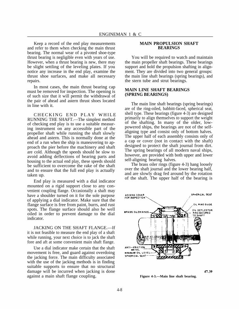
ENGINEMAN 1 & C
Keep a record of the end play measurementsand refer to them when checking the main thrustbearing. The normal wear of a pivoted shoe-typethrust bearing is negligible even with years of use.However, when a thrust bearing is new, there maybe slight settling of the leveling plates. If younotice any increase in the end play, examine thethrust shoe surfaces, and make all necessaryrepairs.
In most cases, the main thrust bearing capmust be removed for inspection. The opening isof such size that it will permit the withdrawal ofthe pair of ahead and astern thrust shoes locatedin line with it.
C H E C K I N G E N D P L A Y W H I L ERUNNING THE SHAFT.—The simplest methodof checking end play is to use a suitable measur-ing instrument on any accessible part of thepropeller shaft while running the shaft slowlyahead and astern. This is normally done at theend of a run when the ship is maneuvering to ap-proach the pier before the machinery and shaftare cold. Although the speeds should be slow toavoid adding deflections of bearing parts andhousing to the actual end play, these speeds shouldbe sufficient to overcome the rake of the shaftand to ensure that the full end play is actuallytaken up.
End play is measured with a dial indicatormounted on a rigid support close to any con-venient coupling flange. Occasionally a shaft mayhave a shoulder turned on it for the sole purposeof applying a dial indicator. Make sure that theflange surface is free from paint, burrs, and rustspots. The flange surface should also be welloiled in order to prevent damage to the dialindicator.
JACKING ON THE SHAFT FLANGE.—Ifit is not feasible to measure the end play of a shaftwhile running, your next choice is to jack the shaftfore and aft at some convenient main shaft flange.
Use a dial indicator make certain that the shaftmovement is free, and guard against overdoingthe jacking force. The main difficulty associatedwith the use of the jacking methods is in findingsuitable supports to ensure that no structuraldamage will be incurred when jacking is doneagainst a main shaft flange coupling.
MAIN PROPULSION SHAFTBEARINGS
You will be required to watch and maintainthe main propeller shaft bearings. These bearingssupport and hold the propulsion shafting in align-ment. They are divided into two general groups:the main line shaft bearings (spring bearings), andthe stern tube and strut bearings.
MAIN LINE SHAFT BEARINGS(SPRING BEARINGS)
The main line shaft bearings (spring bearings)are of the ring-oiled, babbitt-faced, spherical seat,shell type. These bearings (figure 4-3) are designedprimarily to align themselves to support the weightof the shafting. In many of the older, low-powered ships, the bearings are not of the self-aligning type and consist only of bottom halves.The upper half of each assembly consists only ofa cap or cover (not in contact with the shaft)designed to protect the shaft journal from dirt.The spring bearings of all modern naval ships,however, are provided with both upper and lowerself-aligning bearing halves.
The brass oiler rings (figure 4-3) hang looselyover the shaft journal and the lower bearing half,and are slowly drag fed around by the rotationof the shaft. The upper half of the bearing is
Figure 4-3.—Main line shaft bearing.
4-8

Chapter 4—REDUCTION GEARS AND RELATED EQUIPMENT
grooved to accommodate the rings. As they glidethrough the reservoir of oil at the bottom, therings carry some of the oil along to the top of theshaft journal.
On some steam driven ships, the most recentline shaft bearing design employs oiler discsinstead of oiler rings for lubrication. At very lowspeeds (i.e., when the shaft is jacked for 24 hourswhile the turbines are cooling), the oil rings tendto slip and lubrication is sometimes inadequate.The oiler discs are clamped to propulsion shaftand have cavities at the periphery which carry oilto the top of the bearing regardless of the shaftspeed.
Spring bearing temperatures and oil levelsshould be checked hourly while underway. Atleast once each year, the bearings should beinspected, clearances taken, and any defectscorrected.
STERN TUBE AND STERNTUBE BEARINGS
The hole in the hull structure for accom-modating the propeller shaft to the outside of thehull is called the stern tube. The propeller shaft
is supported in the stern tube by two bearings—one at the inner end and one at the outer end ofthe stern tube—called stern tube bearings. At theinner end of the stern tube there is a stuffing boxcontaining the packing gland (figure 4-4), whichis generally referred to as the stern tube gland.The stern tube gland seals the area between theshaft and stern tube but allows the shaft to rotate.
The stuffing box is flanged and bolted to thestern tube. Its casing is divided into twocompartments—the forward space which is thestuffing box proper, and the after space, providedwith a flushing connection, designed to maintaina positive flow of water through the stern tubefor lubricating, cooling, and flushing. Thisflushing connection is supplied by the firemain.A DRAIN CONNECTION is provided both fortesting for the presence of cooling water in thebearing and for permitting sea water to flowthrough the stern tube and cool the bearing whenunderway, where natural seawater circulation isemployed.
The gland for the stuffing box is dividedlongitudinally into two parts. The gland bolts arelong enough to support the gland when the latteris withdrawn at least 1 inch clear of the stuffing
Figure 4-4.—Stern tube stuffing box and gland.
4-9

ENGINEMAN 1 & C
Figure 4-5.—Details of underwater strut bearing. A. Longitudinal view. B. Cross-sectional view. C. Rubber stripping in thebearing.
box. This permits the addition of a ring of newpacking, when needed, while the ship is water-borne. Either braided flax packing or specialsemimetallic packing must be used (ship’sengineering drawings show the proper type ofpacking). This gland is usually tightened toeliminate leakage when the ship is in port, andis loosened (prior to warming up) just enough topermit a slight trickle of water for cooling pur-poses when the ship is underway.
More recent shaft seal designs utilize packingonly for emergencies. These newer seals are of twotypes; rubber face seals and mechanical face seals.
Both face seals are on a plane perpendicular tothe shafting, against a gland ring for rubber faceseal or against a seal ring for a mechanical faceseal. Further, most face seals require seawater forboth cooling and lubrication.
The rubber face consists of a rubber elementthat is clamped around the shaft just tightlyenough to prevent rotational slippage and leakageunderneath the seal, while at the same time, theseal is able to travel axially along the shaft. Thisaxial motion is necessary so that the seal can main-tain its position against the gland ring regardlessof shaft position.
4-10

Chapter 4—REDUCTION GEARS AND RELATED EQUIPMENT
The mechanical face seal is a ring made ofeither a hard synthetic or a carbon compound.This ring is held tightly against the seal ring bysprings mounted behind it.
NOTE: More information on face-type sealsis available in manufactures technical manuals—(Crane Co., “Surface Ship, Seal Inc.“,“Submarine”).
STRUT BEARINGS
The strut bearings, like the stern tube bear-ings, are equipped with composition bushingswhich are split longitudinally into two halves. Theouter surface of the bushing is machined withsteps to bear on matching landings in the bore ofthe strut.
Since it is usually impracticable to use oil orgrease as a lubricant for underwater bearings,some other material must be employed for thatpurpose. Materials that become slippery when wetinclude natural or synthetic rubber; lignum vitae,a hard tropical wood with excellent wearingqualities; and laminated phenolic material
consisting of layers of cotton fabric impregnatedand bonded with phenolic resin. Strips of thismaterial, as shown in view C of figure 4-5, arefitted inside the bearing. A rubber compositionis the type most used in modern installations.
CONTROLLABLE PITCH PROPELLERS
This section will describe the major com-ponents and the principles of operation of the con-trollable reversible pitch (CRP) propeller (a partof the main propulsion system).
COMPONENTS OF THE CRPPROPELLER
Most ships that use CRP propellers use twoindependent units with their associatedmechanical, hydraulic, and electronic pitch con-trol mechanisms, plus all the required valves andseals. Some type ships require tubing and passagesfor the discharge of prairie air through each pro-peller blade. The CRP propellers form an integralpart of the ship’s two shaft main propulsionsystem. Figure 4-6 shows the major componentsof a single CRP propeller.
Figure 4-6.—CRP Propeller Machinery.
4-11

ENGINEMAN 1 & C
Table 4-1.—Related Propulstion System Components
System Name/Description
Main Reduction Gear, Mounting andCoupling for Gear-Driven Hydraulic OilPump.
Propeller Shaft.
Interconnecting Hydraulic Oil Piping.
Head Tank, Sump Tank and Hydraulic OilSupply plus Associated Components, andFittings.
Central Control Station (CCS) Controlsand Indicators.
Related propulsion system components, whichare necessary for the operation of a CRP propellerbut which are not part of the CRP propeller arelisted in table 4-1. Let’s look at some of these com-ponents, along with other components, shown intable 4-2.
Hub/Blade Assembly
The propeller’s hub/blade assembly (see figure4-6), attached to the main propulsion propellershaft, provides the mounting for the propellerblades and houses the blade turning mechanismfor rotating and holding the pitch position of theblades. Attached to the after end of the hub bodyare the hub cone and the hub cone end cover.These items form the chamber for the servomotorpiston. The hub body is fitted to the tailshaft byguide pin dowels which also transmit the torque
Table 4-2.—CRP Propeller Hardware Components
HUB BLADE ASSEMBLY HYDRAULIC SYSTEM
Hub Assembly, LGHub assembly. RHBlades (Set of 5). LHBlades (Set of 5). RH
VALVE ROD ASSEMBLY
Piping, Couplings & Guides, PortPiping, Couplings & Guides, Stbd
OIL DISTRIBUTION BOX
DD Box Assembly. PortDD Box Assembly, Stbd.
ELECTRONIC PITCHCONTROL SYSTEM
Hydraulic Oil Power Module, P/S(each including): Electronic Pitch Control Assembly,
P/SSuction Strainer (1)Hydraulic Oil Pump, Coupling Feedback Potentiometer, P/S
and Motor (1) Readout Potentiometer, P/S
Duplex Discharge Filters (3)Air Bleed Valves (2) LOCAL PITCH INDICATOR
Pressure Control Assembly, con-sisting of: sequence and reliefvalve, unloading and checkvalve, reducing Valve, andcontrol oil relief valve.
Manual Bypass Valve (1)Gauge Panels (2)
Manifold Block Assembly, P/S (eachincluding):
Electra-hydraulic Servo ControlValve (1)
Manual Pitch Control Valve (1)Manual Changeover Valves (2)
Standby Hydraulic Oil Pump (geardriven), P/S
Suction Strainer (gear pump), P/SReturn Check Valve, P/S
Pitch Indicating Assembly, P/S
EMERGENCY PITCH SETTING
Emergency Hand Pump Assembly,P/S
PRAIRIE AIR SYSTEM
Rotoseal, P/SCheck Valve (hub), LH/RHCheck Valve (OD Box), P/SPrairie Air Tube Assy.. P/SConnectors, Prairie Air, Hub to
Blade (Set of 5). LH/RH
4-12

Chapter 4—REDUCTION GEARS AND RELATED EQUIPMENT
from the shafting to the hub assembly. The hubis secured to the tailshaft by flange bolts. Thesebolts are not designed to take torque from the tailshaft. The hub to tailshaft joint is sealed byO-rings located between the hub and the tailshaft,and between the tailshaft and the tailshaft spigot.Each blade is attached to a crank pin ring by bladebolts. The crank pin ring fits over and rotatesabout a center post which is physically a part ofthe hub body. The crank pin ring is retained inthe hub by the bearing ring. The area under eachblade is sealed by the blade port cover and by twoO-rings in the blade seal base ring. Each bladeseal base ring is spring-loaded against the under-side of the blade port cover to provide a sealingsurface under all loading conditions.
The blade turning mechanism in the hub con-sists of a single crosshead, attached to the end ofa piston rod. Several sliding blocks are fittedinto the machined chambers of the crosshead. Aneccentric pin on the underside of each crank pinring fits into a hole machined into each slidingblock. The hub servomotor is attached to the afterend of the crosshead. A piston rod carries the linesfor the regulating valve pin which is attached tothe end of the valve rod. This assembly forms apassage for hydraulic power oil flow and returnoil flow to and from the hub.
class and DD 963 class ships, is mounted to theforward end of the main reduction gear and isflange-connected to the main reduction gear shaftcoupling. The other type, used on the LST1179-1198 class ships, is called the Bird-JohnsonKamewa Unit; it is manufactured of steel, is castin two sections, and is line-bored for installationover the intermediate shaft. The OD box providesa direct hydraulic oil connection to the main pro-pulsion shaft and also translates to the valve rodin response to hydraulic control oil commands.High pressure oil from the hydraulic oil powermodule (HOPM) is introduced through the ODbox to the internal bore of the valve rod and tothe hub. The oil returns from the propeller hubto the hydraulic oil sump tank by way of the an-nulus between the valve rod and the internal boreof the shafting, through the OD box.
Hydraulic System
Valve Rod Assembly
The valve rod assembly is composed offabricated sections of seamless steel tubingjoined by couplings to provide a mechanical linkbetween the oil distribution (OD) box and the hubservomotor through the internal bore of thepropeller shaft. The valve rod assembly providesa passage for high pressure hydraulic oil from theoil distribution box to the hub. Each valve sec-tion is supported at the center of the propellershaft bore by guides. The after end of the valverod assembly supports a regulating valve pinwhich operates in the valve pin liner of the hubservomotor. The forward end of the valve rodassembly is mechanically linked to the OD boxshaft, so that the valve rod assembly turns withthe shaft.
The hydraulic system consists of a self-contained HOPM, a standby hydraulic pumpdriven by the main reduction gear, the pitch con-trol valves manifold block assembly, and all theassociated connecting piping, fittings, and valves.The hydraulic oil is supplied to the hydraulic oilpumps from a separate sump tank. To maintaina static head pressure when the hydraulic systemis shut down, a gravity head tank is connected tothe OD box.
Oil Distribution Box
Presently there are two types of OD boxesbeing used in the Navy. One type, used on FFG-7
HYDRAULIC OIL POWER MODULE.—The HOPM is located adjacent to the main reduc-tion gear. It is a RESILIENT mounted, weldedstructural assembly, consisting of a base plate withstructural ANGLE bar, flat bar, and mountingplates. The HOPM contains the major com-ponents of the hydraulic system, including (1)either the motor-driven hydraulic screw or thevane pump, coupling, and AC motor; (2) a suc-tion strainer for the motor-driven pump; (3) two40 micron duplex discharge filters; (4) the pressurecontrol assembly operating valves, which consistof a pressure reducing valve, an auxiliary reliefvalve, a check valve, an unloading and checkvalve, and a relief and sequence valve; (5) one 10micron duplex control oil filter; (6) a gauge panelassembly and associated instrumentation; (7) amanual bypass valve; and (8) the interconnectingpiping and fittings.
4-13

STANDBY PUMP.—The standby pump is ofthe same type as the main hydraulic pump, butit is mounted at the forward end of the mainreduction gear housing and is driven through adisconnect coupling. The suction strainer and suc-tion gauge for this pump are mounted separately.The primary function of the standby pump is toassist the main pump in effecting pitch changes.When the control pitch (C/P) unit is in the holdingpitch position, the standby pump discharge oil isunloaded back to the sump through the hydraulicblock. But, whenever a pitch change is ordered,the pump discharge oil is directed to the hydraulicblock high pressure passage.
LOWER OIL TANK.—The lower (sump) oiltank is usually located aft and below the OD boxassembly. The oil capacity of the sump variesdepending on the type and class of ship. Twopumps, the main and standby hydraulic pumps,take suction on the lower oil tank through a footvalve, which permits the oil to flow from the tankbut does not allow it to return through the suc-tion line.
UPPER GRAVITY OIL TANK.—This tankis located above the maximum draft line. Its mainpurpose is to maintain hub oil pressure above thatof the surrounding seawater when the C/P unitis secured. In the Kamewa installation, theupper gravity oil tank serves an additional pur-pose. During C/P unit operation the tank assistsin maintaining the sliding ring chamber pressure.
PRINCIPLES OF OPERATION
The CRP propeller provides the ahead andastern propulsion thrust for a vessel by a changein the pitch of the propeller blades. Such changescan be obtained even when the main propulsionmachinery, including the propeller shaft, areturning at a high rate of speed. Blade pitch con-trol permits a full range of ahead and asternthrusts. Maximum ahead thrust is provided withthe blades in the full ahead pitch position, andmaximum astern thrust is provided with the bladesin the full astern pitch position. When the pro-peller blades are set at zero thrust, the propellershaft may be turning at any speed without im-parting thrust to the vessel.
When a change of propeller pitch position isordered, a pitch position command from the pro-pulsion control system is fed to the controls. Thiscommand signal activates the electrohydraulic ser-vocontrol valve which, in turn, activates the flowof control oil to and from the OD box to changethe position of the valve rod actuator. Thehydraulic power oil flows to the OD box and isadmitted to the valve rod via the annular chamberin the OD box and the ports in the valve rod. Theoil flows within the bore of the valve rod to thehub servomotor, and returns from the hub via apassage formed between the valve rod and thepropulsion shaft bore. ‘The oil leaves the OD boxvia ports in the OD box shaft and the annularchamber to return to the sump tank. Control oilis regulated by a set of sequencing and reducingvalves in the hydraulic system which maintain therequired pressure level. Control oil is supplied tothe electrohydraulic servocontrol valve. From theservocontrol valve, the control oil flows to oneside of the low pressure (LP) chamber of the ODbox to drive the valve rod actuator. Control oilreturns to the sump through the OD box manifoldfrom the other side of the LP chamber.
When the propeller is operating at the desiredblade pitch position, the OD box valve rodactuator is hydraulically locked and the hub ser-vomotor is hydraulically held in a stationary posi-tion. The configuration of the regulating valve pinin the hub servomotor allows hydraulic power oilto circulate continuously through the hub servo.The oil pressure developed on each side of the hubservomotor piston is balanced and established atthe level necessary to counteract blade loadingwhich would tend to change pitch position. Ahydraulic pitch change signal from the elec-trohydraulic servo control valve moves the valverod actuator and the valve rod. This movementchanges the size of the oil passages to each faceof the hub servomotor piston, thereby creatinga differential pressure in the circulating oil to eachface of the piston. The regulating valve pin thensupplies high pressure oil to one face of the pistonand connects the other face to the return oilpassage. The high pressure oil develops thenecessary pressure on the piston face to overcomeblade loading and move the turning mechanismand the blades to the desired pitch position. Bladepitch will continue to change until the oil portopenings equalize and the oil pressure developed
ENGINEMAN 1 & C
4-14

on each face of the piston is balanced.Removing the oil signal from the valve rodactuator stops motion in the valve rod and thehub servomotor. The self-centering feature of theservomotor over the regulating valve pin providesthe res tor ing force to counterac t anyhydrodynamic tendency to change pitch from thatset by the command signal.
INSPECTIONS
The inspections mentioned here are theminimum requirements for reduction gears.Where defects are suspected, or operating condi-tions so indicate, inspections should be made atmore frequent intervals.
No inspection plates or other fittings of themain reduction gear may be opened without thepermission of the engineer officer. Before replac-ing of an inspection plate, connection, fitting, orcover which permits access to the gear casing,make a careful inspection to ensure that noforeign matter has entered or remains in the cas-ing or oil lines. An entry of the inspections, andthe name of the CPO or officer who witnesses theclosing of the inspection plate, should be madein the Engineering Log.
PMS INSPECTIONS
The PMS requirements discussed in this sec-tion are general in scope. Inspection requirementsfor your ship are listed in the ship’s PMS Manualand should be referred to for all maintenanceaction.
Gears should be jacked DAILY—ATANCHOR—so that the main gear shaft ismoved 1 1/4 revolutions. This jacking should bedone with lubricating oil circulating in the system.
You should take the following actionsQUARTERLY:
1. Sound with a hammer the holding downbolts, ties, and chocks to detect signs of loosen-ing of casing fastenings.
2. Open inspection plates, inspect gears, andoil-spray nozzles. Wipe off oil at different pointsand note whether the surface is bright or if alreadycorroded, and whether or not new areas areaffected.
3. Inspect the strainers for the oil-spraynozzles to see that dirt or sediment has notaccumulated in them.
4. Take and record all main thrust bearingreadings.
When conditions warrant or if trouble issuspected, a work request should be submitted toa naval shipyard to perform a 7-YEAR INSPEC-TION of the main reduction gears. This inspec-tion includes clearance readings of bearings andjournals; alignment checks and readings; and anyother inspections, tests, or maintenance work thatmay be considered necessary.
If the ship’s propeller strikes ground or asubmerged object, a careful inspection should bemade of the main reduction gear immediatelyfollowing the OCCURRENCE of the casualty. Inthis inspection, the possible misalignment of thebull gear and its shaft should be considered.Where practicable, a naval shipyard should be re-quested to check the alignment and concentricityof the bull gear.
NAVAL SHIPYARD OVERHAUL
During a naval shipyard overhaul, the fol-lowing work should be performed: inspection ofthe condition and clearance of thrust shoes to en-sure proper position of gear; inspection of thethrust collar, nut, and locking device; and inspec-tion of the flexible couplings between turbines andreduction gears and removal of the sludgedeposits.
FULL POWER TRIALS
The correction of any defect disclosed byregular tests and inspections, and the conscien-tious observance of the manufacturers’ instruc-tions, should assure that the gears are ready forfull power at all times.
It is not advisable to open up gear cases,bearings, and thrusts immediately BEFORETRIALS. In addition to the inspections whichmay be directed by proper authority which areconducted during the FULL POWER TRIALS,the following checks must be made AFTERTRIALS. Open the inspection plates, and examinethe tooth contact and the condition of the teethto note changes that may have occurred during
Chapter 4—REDUCTION GEARS AND RELATED EQUIPMENT
4-15

ENGINEMAN 1 & C
the trials. (Running for a few hours at high powerwill show any possible condition of improper con-tact or abnormal wear that would not have shownup in months of operation at lower powers.)Check the clearance of the main thrust bearing.
SAFETY PRECAUTIONS
Observe the following safety precautionswhich apply to the operation, care, andmaintenance of reduction gears and related equip-ment found on Navy ships.
1. If churning or emulsification of the oil inthe gear case occurs, the gear must be sloweddown or stopped until the defect is remedied.
2. If the supply of lubricating oil to the gearsfails, the gears should be stopped and the causelocated and remedied.
3. When bearings have been overheated, thegears should NOT be operated—except in extremeemergencies—until bearings have been examinedand defects have been remedied.
4. If excessive flaking of metal from the gearteeth occurs, the gears should not be adjusted, ex-cept in case of emergency, until the cause has beendetermined.
5. Unusual noises should be investigated atonce, and the gears should be operated cautiouslyor stopped until the cause for the noise has beendiscovered and remedied.
6. No inspection plate, connection, fitting,or cover which permits access to the gear casingshould be removed without specific authority ofthe engineer officer.
7. The immediate vicinity of an inspectionplate joint should be kept free from paint and dirt.
8. When gear cases are open, precautionsshould be taken to prevent the entry of foreignmatter. The openings should never be left unat-tended unless satisfactory temporary closures havebeen installed.
9. Lifting devices should be inspectedcarefully before being used and should not beoverloaded.
10. Naked lights should be kept away fromvents while gears are in use (the oil vapor may beexplosive).
11. Ships anchored in localities where thereare strong currents or tides should take precau-tions and lock the main shafts.
12. When divers are in the vicinity of the pro-peller, propeller shafts should be locked.
13. When a shaft is allowed to turn or trail,the lubrication system must be in operation.
14. The main propeller shaft must be broughtto a dead stop position before an attempt is madeto engage or disengage the turning gear.
15. When a main shaft is being locked,precautions must be taken to apply the brakequickly and securely.
16. Where there is a limiting maximum safespeed at which a ship can steam with a locked pro-peller shaft, this speed should not be exceeded.
17. When the main gears are being jackedover, precautions must be taken to see that theturning gear is properly lubricated.
18. Before the main engines are started, itshould be definitely determined that the turninggear has been disengaged.
4-16

CHAPTER 5
ENGINE PERFORMANCE AND EFFICIENCY
Your prime concern as an Engineman is tokeep the machinery for which you are responsi-ble operating in the most efficient manner possi-ble. From your past experience and training, youknow that engine efficiency and performancedepend upon much more than just operating thethrottle and changing oil at prescribed intervals.The preceding chapters have covered many of thecasualties which may occur to reduce the poweroutput of an engine. You have learned how to pre-vent the occurrence of many of these casualties.As you gain experience and understanding, youwill probably have to train other people. The peo-ple you will train will frequently come up withmany questions about why an engine does or doesnot perform efficiently. Will you be able to answertheir questions?
To understand the various factors thatinfluence engine performance and efficiency, athorough knowledge of the internal combustionprocess is necessary. Once the combustionprocess is understood, it will be much easier foryou to appreciate the part played by such factorsas engine design, engine operating conditions, fuelcharacteristics, fuel injection, ignition, pressuresand temperatures, and compression ratios. Thischapter provides some of the informationnecessary for a better understanding of the manyfactors that affect engine performance and effi-ciency. As an Engineman, you will be able to gaincomplete understanding of such factors onlythrough continued study and practical experience.
You should know how the power which anengine can develop is limited by such factors asthe mean effective pressure, the length of pistonstroke, the cylinder bore, and the engine speed.You must also know how these factors are usedin determining the power developed by an engine.You must learn how heat losses, efficiency of
combustion, volumetric efficiency, and theproper mixing of fuel and air limit the powerwhich a given engine cylinder can develop. Youmust become familiar with the factors which causeoverloading of an engine and unbalance betweenengine cylinders. You should know the symptoms,causes, and effects of cylinder load unbalance andthe steps that are necessary to maintain an equalload on each cylinder.
You must know what is meant by engineefficiency and know how the various types ofefficiencies and losses are used in analyzing theinternal combustion process. You must also befamiliar with those factors which may cause theefficiencies to increase or decrease, and with theways these variations affect engine performance.
Parts of this chapter may serve as a briefreview, but most of the information provideddeals with those factors that influence engine per-formance and efficiency.
ENGINE PERFORMANCE
In addition to mechanical difficulties, anyengine performance may be affected by othercauses, such as engine design and operator’s per-formance. A comparison of the principal condi-tions which influence the performance ofinternal combustion engines is given in table 5-1.Note that the performance conditions for the twotypes of engines (diesel and gasoline) aresomewhat similar, except for some differences dueto factors dealing with fuel and ignition.
POWER LIMITATIONS
The design of an engine limits the amount ofpower that an engine can develop. Other limiting
5-1

ENGINEMAN 1 & C
Table 5-1.—Factors That Influence Engine Performance
1. Fuel characteristics
2. Compression ratio
3. Engine operating conditions
Combustion chamber design
Valve arrangements
Size of valves
Manifold arrangements
Hot spots (presence/absence)
Location of spark plugs
Number of spark plugs
4. Pressure and temperature of air in the engine cylinderat start of compression
5. Pressure/temperature of the charge in the enginecylinder at the start of compression
factors are the mean effective pressure, the lengthof stroke, the cylinder bore, and the number ofrevolutions per minute (piston speed) of theengine. The latter, piston speed, is limited by thefrictional heat and by the inertia of the movingparts.
Mean Effective Pressure
The mean effective pressure (MEP) is theaverage pressure exerted on the piston during eachpower stroke, and is determined from a formulaor by means of a planimeter. There are two kindsof mep: indicated mean effective pressure (imep),which is developed in the cylinder and can bemeasured; and brake mean effective pressure(bmep), which is computed from the brakehorsepower (bhp) delivered by the engine.
Diesel Engines
X
X
X
X
X
X
X
X
Gasoline Engines
X
X
X
X
X
X
X
X
X
X
Length of Stroke
The distance a piston travels between top andbottom dead centers (TDC, BDC) is known as thelength of stroke. This distance is one of the fac-tors that determines the piston speed. In somemodern diesel engines, piston speeds may reachabout 1600 feet per minute (fpm).
Cylinder Bore
Bore is used to identify the diameter of thecylinder. The cylinder bore must be known inorder to compute the area of the piston crownupon which the pressure acts to create thedriving force. This pressure is calculated and ex-pressed for an area of one square inch as poundsper square inch (psi).
5-2

Chapter 5—ENGINE PERFORMANCE AND EFFICIENCY
The ratio of length of stroke to cylinder bore Using the factors which influence the engine’sis fixed in engine design; in most slow speed capacity to develop power, the general orengines, the stroke is greater than the bore. standard formula for calculating ihp is as follows:
Revolutions Per Minute
Revolutions per minute (rpm) is the speed atwhich the crankshaft rotates. Since the piston isconnected to the shaft, the rpm, along with thelength of the stroke, determine piston speed.Since, during each revolution, the piston com-pletes one up-stroke and one down-stroke, pistonspeed is obtained by multiplying the rpm by twicethe length of the stroke. This speed is usually ex-pressed in feet per minute (fpm). If the stroke is10.5 inches (or 10.5/12 of a foot), and the speedof rotation is 720 rpm, the piston speed is com-puted as follows:
HORSEPOWER COMPUTATION
The power developed by an engine dependsupon the type of engine as well as the speed ofthe engine. A cylinder of a single-acting, 4-strokecycle engine will produce one power stroke forevery two crankshaft revolutions, while a single-acting, 2-stroke cycle engine produces one powerstroke for each revolution.
Indicated Horsepower
The power developed within a cylinder can becalculated by measuring the imep and the enginespeed. (The rpm of the engine is converted to thenumber of power strokes per minute.) With thebore and stroke known (available in enginemanufacturers’ technical manuals), thehorsepower (hp) can be computed. This power iscalled indicated horsepower (ihp) because it is ob-tained from the pressure measured with an engineindicator. Power loss due to friction is not con-sidered in computing ihp.
ihp = P × L × A × N33,000
where
P = Mean indicated pressure, in psi
L = Length of stroke, in feet
A = Effective area of the piston, insquare inches
N = Number of power strokes per minute
33,000 = Unit of power (one horsepower), orfootpounds per minute.
To illustrate the use of this formula, assumethat a 12-cylinder, 2-stroke cycle, single-actingengine has a bore of 8.5 inches and a stroke of10 inches. Its rated speed is 744 rpm. With theengine running at full load and speed, the imepis measured and found to be 105 psi. What is theihp developed by the engine?
In this case
Substituting these amounts in the formula,you have
This amount represents the horsepowerdeveloped in only one cylinder; since there are 12cylinders in this engine, total horsepower for theengine will equal 12 times 111.9, or approximately1343.
5-3

Brake Horsepower
Brake horsepower (bhp), sometimes calledshaft horsepower, is the amount of poweravailable for useful work. Bhp is less than ihpbecause of the various power losses which occurduring engine operation.
To determine the brake or shaft horsepowerthat is delivered as useful work by an engine, thesum total of all mechanical losses must bededucted from the total ihp.
CYLINDER PERFORMANCELIMITATIONS
The factors which limit the power that a givencylinder can develop are the piston speed and themep. The piston speed, as stated before, is limitedby the inertia forces set up by the moving partsand by frictional heat. In the case of the mep, thelimiting factors are as follows:
1. Heat losses and efficiency of combustion.
2. Volumetric efficiency (the amount of aircharged into the cylinder and the degree ofscavenging).
3. Mixing of the fuel and air.
The limiting meps, both bmep and imep, areprescribed by the manufacturer or NAVSEA.They should never be exceeded. In a direct-driveship, the meps developed are determined by therpm of the power shaft. In electric-drive ships,the horsepower and bmep are determined by acomputation based on readings from electrical in-struments and from generator efficiency.
CYLINDER LOAD BALANCE
In order to ensure a balanced, smooth-operating engine, the general mechanical condi-tion of the engine must be properly maintainedso that the power output of the individualcylinders is within the prescribed limits at all loadsand speeds. In order to have a balanced load onthe engine, each cylinder must produce its shareof the total power developed. If the engine isdeveloping its rated full power, or nearly so, andone cylinder or more is producing less than its
share, the remainder of the cylinders will becomeoverloaded.
Using the rated speed and bhp, it is possibleto determine for each INDIVIDUAL CYLINDERa rated bmep which may not be exceeded withoutoverloading the cylinder. If the ENGINE rpmdrops below the rated speed, then the cylinderbmep generally drops to a lower value. The bmepshould never exceed the normal mep at lowerengine speed. Usually, it should be somewhatlower if the engine speed is decreased.
Some engine manufacturers design the fuelsystems so that it is impossible to exceed the ratedbmep. This is done by installing a positive stopto limit the maximum throttle or fuel control. Thispositive stop regulates the maximum amount offuel that can enter the cylinder and limits themaximum load of the cylinder.
In order to meet emergency situations, enginesused by the Navy are generally rated lower thanthose designed for industrial use. The economicalspeed for most of the Navy’s diesel engines isapproximately 90% of the rated speed. For suchspeed, the best load conditions have been foundto be from 70% to 80% of the rated load or out-put. When an engine is operated at an 80-90 com-bination (80% of rated load at 90% rated speed)the parts last longer and the engine remainscleaner and in better operating condition.
Diesel engines do not operate well at ex-ceedingly low bmep such as that occurring atidling speeds. You are well aware that idling anengine tends to gum up parts associated with thecombustion spaces. Operating an engine at idlingspeeds for long periods will result in thenecessity for cleaning and overhauling the enginemuch sooner than when operating at 50 to 100%of load.
Symptoms of Unbalance
Evidence of an unbalanced condition betweenthe cylinders of an engine may be indicated bythe following symptoms:
1. Black exhaust smoke. When this occurs,it is not always possible to determine immediatelywhether the entire engine or just one of thecylinders is overloaded. To determine whichcylinder is overloaded, you must open the
ENGINEMAN 1 & C
5-4

indicator cock on each individual cylinder andcheck the color of the exhaust.
2. High exhaust temperatures. If thetemperatures of exhaust gases from individualcylinders become higher than normal, it is an in-dication of an overload within the cylinder. If thetemperature of the gases in the exhaust headerbecomes higher than usual, it is an indication thatall cylinders are probably overloaded. Frequentchecks on the pyrometer will indicate whethereach cylinder is firing properly and carrying itsshare of the load. Any sudden change in theexhaust temperature of any cylinder should beinvestigated immediately. The difference in ex-haust temperatures between any two cylindersshould not exceed the limits prescribed in theengine manufacturer’s technical manual.
3. High lubricating oil and cooling watertemperatures. If the temperature gages for thesesystems show an abnormal rise in temperature,an overloaded condition may exist. The causes ofthe abnormal temperature in these systems shouldbe determined and corrected immediately if engineefficiency is to be maintained.
4. Excessive heat. In general, excessive heatin any part of the engine may indicateoverloading. An overheated bearing may be theresult of an overloaded cylinder; or an abnormallyhot crankcase may be the result of overloadingthe engine as a whole.
5. Excessive vibration or unusual sound. Ifall cylinders are not developing an equal amountof power, the forces exerted by individual pistonswill be unequal. When this occurs, the unequalforces cause an uneven turning movement to beexerted on the crankshaft, and vibrations are setup. Through experience, you will learn to tell bythe vibrations and sound of an engine when a poordistribution of load exists. You should use everyopportunity to observe and listen to enginesrunning under all conditions of loading andperformance.
Causes of Unbalance
An engine must be kept in excellentmechanical condition to prevent unbalance. Aleaky valve or fuel injector, leaky compressionrings, or any other mechanical difficulties willmake it impossible for you to balance the load
unless you secure the engine and dismantle at leasta part of it.
To obtain equal load distribution betweenindividual cylinders, the clearances, tolerances,and the general condition of all parts that affectthe cycle must be maintained so that very little,if any, variation exists between individualcylinders. Unbalance will occur unless the follow-ing conditions are as nearly alike as possible forall cylinders:
1. Compression pressures
2. Fuel injection timing
3. Quantity and quality of fuel injected
4. Firing pressures
5. Valve timing and lift
When unbalance occurs, correction usually in-volves repair, replacement, or adjustment of theaffected part or system. Before any adjustmentsare made to eliminate unbalance, it must be deter-mined beyond any doubt that the engine is inproper mechanical condition. When an engine isin good mechanical condition, few adjustmentswill be required. However, after an overhaul inwhich piston rings or cylinder liners have beenrenewed, considerable adjustment may benecessary. Until the rings become properly seated,some lubricating oil will leak past the rings intothe combustion space. This excess oil will burnin the cylinder, giving an incorrect indication offuel oil combustion. If the fuel pump is set fornormal compression, and the rings have not seatedproperly, the engine will become overloaded. Asthe compression rises to normal pressures, therewill be an increase in the power developed, as wellas in the pressure and temperature under whichthe combustion takes place. Therefore, when anoverhaul has been completed, the engineinstruments must be carefully watched until therings are seated, and all necessary adjustments aremade. Frequent compression tests will serve as ahelpful aid in making the necessary adjustments.Unless an engine is so equipped that compressioncan be readily varied, the engine should beoperated under light load until the rings areproperly seated.
Chapter 5—ENGINE PERFORMANCE AND EFFICIENCY
5-5

ENGINEMAN 1 & C
Effect of Unbalance
From the preceding discussion, it can bereadily seen that, in general, the result of un-balance will be overheating of the engine. Theclearances established by the engine designer allowfor sufficient expansion of the moving parts whenthe engine is operating at the designedtemperatures, but an engine operating attemperatures in excess of those for which it wasdesigned is subject to many casualties. Excessiveexpansion soon leads to seizure and burning ofthe engine parts. Should the temperatures in thecrankcase rise above the flash point of thelubricating oil vapors, an explosion may result.High temperature may destroy the oil film be-tween adjacent parts, and the resulting increasedfriction will further increase the temperature.
4. Keep cylinder temperatures and pressuresas evenly distributed as possible.
5. Train yourself to recognize the symptomsof serious engine conditions.
ENGINE EFFICIENCY
Engine efficiency is the amount of powerdeveloped as compared to the energy input whichis measured by the heating value of the fuel con-sumed. The term “efficiency” is used to designatethe relationship between the result obtained andthe effort expended to produce the result.
Since power is directly proportional to the mepdeveloped in a cylinder, any increase in mep willcause a corresponding increase in power. If themeps in the individual cylinders vary, power willnot be evenly distributed among the cylinders.
The term “compression ratio” is frequentlyused in connection with engine performance.From your study of the principles of internal com-bustion, you will recall that compression ratio isthe ratio of the volume of air above the piston,when the piston is at the BDC position, to thevolume of air above the piston when the pistonis at the TDC position.
EFFICIENCIESThe quality of combustion obtained depends
upon the heat content of the fuel. The amountof heat available for power depends upontemperature. Temperature varies directly aspressure; therefore a decrease in pressure willresult in a decrease in temperature, and in poorcombustion. Poor combustion will cause loweredthermal efficiency and reduced engine output.
The principal efficiencies which must beconsidered in the internal combustion process arecycle, thermal, mechanical, and volumetric.
Cycle Efficiency
Cylinder load balance is essential if the desiredefficiency and performance of an engine is to beobtained. To avoid the harmful effects ofoverloading and unbalancing of load, the load onan engine should be properly distributed amongthe working cylinders; and no cylinder, or theengine itself, should ever be overloaded.
In general, load balance in an engine can bemaintained if the following procedures areobserved:
1. Maintain the engine in proper mechanicalcondition.
2. Adjust the fuel system according to themanufacturer’s instructions.
3. Operate the engine within the temperaturelimits specified in appropriate instructions.
The efficiency of any cycle is equal to the out-put divided by the input. The efficiency of thediesel cycle is considerably higher than the Ottoor constant volume cycle because of higher com-pression ratio and because combustion starts ata higher temperature. In other words, the heatinput in a diesel engine is at a higher averagetemperature. Theoretically, a gasoline engineusing the Otto cycle would be more efficient thanthe diesel engine if equivalent compression ratioscould be used. However, engines operating on theOtto cycle cannot use a compression ratio com-parable to that of diesel engines because fuel andair are drawn together into the cylinder and com-pressed. If comparable compression ratios wereused, the fuel would fire or detonate before thepiston reached the correct firing position.
Since temperature and amount of heat con-tent which is available for power are proportional
5-6

to each other, the cycle efficiency is actually com-puted by measuring the temperature. The specificheat of the mixture in the cylinder is either knownor assumed, and when combined with thetemperature, the heat can be calculated at anyinstant.
Thermal Efficiency
Thermal efficiency is the measure of the effi-ciency and completeness of combustion of thefuel, or, more specifically, the ratio of the out-put or work done by the working substance in thecylinder in a given time to the input or heat energyof the fuel supplied during the same time. Twokinds of thermal efficiency are generally con-sidered for an engine: indicated thermal efficiencyand overall thermal efficiency.
Since the work done by the gases in thecylinder is called indicated work, the thermalefficiency determined by its use is often called IN-DICATED THERMAL EFFICIENCY (ite). If allthe potential heat in the fuel could be deliveredas work, the thermal efficiency would be 100%.Because of the various losses, however, this per-cent is not possible in actual installations.
If the amount of fuel injected is known, thetotal heat content of the injected fuel can be deter-mined from the heating value, or Btu per pound,of the fuel; and the thermal efficiencies for theengine can then be calculated. From themechanical equivalent of heat (778 foot-poundsequal 1 Btu and 2545 Btu equal 1 hp-hr), thenumber of foot-pounds of work contained in thefuel can be computed. If the amount of fuelinjected is measured over a period of time, therate at which the heat is put into the engine canbe converted into potential power. Then, if theihp developed by the engine is calculated, aspreviously explained, the indicated thermal effi-ciency can be computed by the followingexpression:
ite =hp × 2545 Btu per hr per hp
Rate of heat input of fuel in Btu per hr× 100
For example, assume that the same engineused as an example in computing ihp consumes360 pounds (approximately 50 gallons) of fuel per
hour, and that the fuel has a value of 19,200 Btuper pound. What is the ite of the engine?
The work done per hour when 1343 ihp aredeveloped is 1343 × 2545 or 3,417,935 Btu. Theheat input for the same time is 360 × 19,200 or6,912,000 Btu. Then, by the above expression, theindicated thermal efficiency is as follows:
The other type of thermal efficiency—OVERALL THERMAL EFFICIENCY—considered for an engine is a ratio similar to ite,except that the useful or shaft work (bhp) isused. Therefore, overall efficiency (often calledbrake thermal efficiency) is computed by thefollowing expression:
Overall thermal efficiency =
bhpHeat input of fuel × 100
Converting these factors into the same units(Btu), the expression is written as power outputin Btu divided by fuel input in Btu.
For example, if the engine used in thepreceding problem delivers 900 bhp (determinedby the manufacturer) what is the overall thermalefficiency of the engine?
1 hp-hr = 2545 Btu
900 bhp × 2545 Btu per hp-hr =
2,290,500 Btu output per hr
Substituting factors already known, overallthermal efficiency is computed as follows:
Overall thermal efficiency =
2,290,5006,912,000
= 0.331, or 33.1%
Chapter 5—ENGINE PERFORMANCE AND EFFICIENCY
5-7

Compression ratio influences the thermalefficiency of an engine. Theoretically, the ther-mal efficiency increases as the compression ratiois increased. The minimum value of a diesel enginecompression ratio is determined by the compres-sion required for starting; and this compressionis, to a large extent, dependent on the type of fuelused. The maximum value of the compressionratio is not limited by the fuel used, but is limitedby the strength of the engine parts and theallowable engine weight per bhp output.
Mechanical Efficiency
This is the rating that shows how much of thepower developed by the expansion of the gasesin the cylinder is actually delivered as usefulpower. The factor which has the greatest effecton mechanical efficiency is friction within theengine. The friction between moving parts in anengine remains practically constant throughoutthe engine’s speed range. Therefore, themechanical efficiency of an engine will be highestwhen the engine is running at the speed at whichmaximum bhp is developed. Since power outputis bhp, and the maximum horsepower availableis ihp, then
bhpMechanical efficiency = ihp × 100
During the transmission of ihp through thepiston and connecting rod to the crankshaft, themechanical losses which occur may be due to fric-tion, or they may be due to power absorbed. Fric-tion losses occur because of friction in the variousbearings, between piston and piston rings, andbetween piston rings and the cylinder walls. Poweris absorbed by valve and injection mechanisms,and by various auxiliaries, such as the lubricatingoil and water circulating pumps and the scavengeand supercharge blowers. As a result, the powerdelivered to the crankshaft and available fordoing useful work (bhp) is less than indicatedpower.
The mechanical losses which affect the effici-ency of an engine may be called frictionalhorsepower (fhp) or the difference between ihpand bhp. The fhp of the engine used in
the preceding examples, then, would be1343 (ihp) – 900 (bhp) = 443 fhp, or 33% ofthe ihp developed in the cylinders. Then, usingthe expression for mechanical efficiency, thepercentage of power available at the shaft is com-puted as follows:
900Mechanical efficiency = 1343 = 0.67, or 67%
When an engine is operating under part load,it has a lower mechanical efficiency than whenoperating at full load. The explanation for thisis that most mechanical losses are almost indepen-dent of the load, and therefore, when loaddecreases, ihp decreases relatively less than bhp.Mechanical efficiency becomes zero when anengine operates at no load because then bhp = 0,but ihp is not zero. In fact, if bhp is zero and theexpression for fhp is used, ihp is equal to fhp.
To show how mechanical efficiency is lowerat part load, assume the engine used in precedingexamples is operating at three-fourths load. Brakehorsepower at three-fourths load is 900 × 0.75or 675. Assuming that fhp does not change withload, fhp = 443. The ihp is, by expression, thesum of bhp and fhp.
ihp = 675 + 443 = 1118
Mechanical efficiency = 675/1118 = 0.60, or60%; this is appreciably lower than the 67%indicated for the engine at full load.
Bmep is a useful concept when dealing withmechanical efficiency. Bmep can be obtained ifthe standard expression for computinghorsepower (ihp) is applied to bhp instead of ihpand the mean pressure (p) is designated as bmep.
bhp = (bmep) × L × A × N33,000
or
33,000 × bhpbmep = L × A × N
From the relations between bmep, bhp, ihp,and mechanical efficiency, by designating
ENGINEMAN 1 & C
5-8

Chapter 5—ENGINE PERFORMANCE AND EFFICIENCY
indicated mean effective pressure by imep in theexpression, one can also show:
bmep = imep × mechanical efficiency
type meter) the amount of air taken in by theengine, converting the amount to volume, andcomparing this volume to the piston displacement.
Volumetric efficiency =To illustrate this, the bmep for the engine in
preceding examples at full load and three-fourthsload is computed as follows:
Volume of air admitted to cylinderVolume of air equal to piston displacement
× 100
33,000 × bhp 33,000 × 900
bmep12 12
=L × A × N = 10 × 56.14 × 744
12
= 70 psi
or
The concept of volumetric efficiency does notapply to 2-stroke cycle engines. Instead, the term“scavenge efficiency” is used. Scavenge efficiencyshows how thoroughly the burned gases areremoved and the cylinder filled with fresh air. Asin the case of a 4-stroke cycle engine, it is desirablethat the air supply be sufficiently cool. Scavengeefficiency depends largely upon the arrangementof the exhaust, scavenge air ports, and valves.
bmep = imep × mechanical efficiency
= 105 × 67, or 70 psiENGINE LOSSES
Bmep gives an indication of the load an enginecarries, and what the output is for piston displace-ment. As the bmep for an engine increases, theengine develops greater horsepower per pound ofweight. For a given engine, bmep changes in directproportion with the load.
Volumetric Efficiency
As the heat content of a fuel is transformedinto useful work, during the combustion process,many different losses take place. These losses canbe divided into two general classifications: ther-modynamic and mechanical. The net useful workdelivered by an engine is the result obtained bydeducting the total losses from the heat energyinput.
The volumetric efficiency of a 4-stroke engineis the relationship between the quantity of intakeair and the piston displacement. In other words,volumetric efficiency is the ratio between thecharge that actually enters the cylinder and theamount that could enter under ideal conditions.Piston displacement is used since it is difficult tomeasure the amount of charge that would enterthe cylinder under ideal conditions. An enginewould have 100% volumetric efficiency if, at at-mospheric pressure and normal temperature, anamount of air exactly equal to piston displacementcould be drawn into the cylinder. This is not possi-ble, except by supercharging, because the passagesthrough which the air must flow offer a resistance,the force pushing the air into the cylinder is onlyatmospheric, and the air absorbs heat during theprocess. Therefore, volumetric efficiency is deter-mined by measuring (with an orifice or venturi
Thermodynamic Losses
Losses of this nature are a result of the follow-ing: loss to the cooling and lubricating systems;loss to the surrounding air; loss to the exhaust;and loss due to imperfect combustion.
Heat energy losses from both the cooling watersystems and the lubricating oil system are alwayspresent. Some heat is conducted through theengine parts and radiated to the atmosphere orpicked up by the surrounding air by convection.The effect of these losses varies according to thepart of the cycle in which they occur. The heatof the jacket cooling water cannot be taken as atrue measure of heat losses, since all this heat isnot absorbed by the water. Some heat is lost tothe jackets during the compression, combustion,and expansion phases of the cycle; some is lost
5-9

ENGINEMAN 1 & C
(to the atmosphere) during the exhaust stroke; andsome is absorbed by the walls of the exhaustpassages.
Heat losses to the atmosphere through theexhaust are unavoidable. This is because theengine cylinder must be cleared of the hot exhaustgases before the next air intake charge can bemade. The heat lost to the exhaust is determinedby the temperature within the cylinder when ex-haust begins. The amount of fuel injected and theweight of air compressed within the cylinder arethe controlling factors. Improper timing of theexhaust valves, whether too early or too late, willresult in increased heat losses. If too early, thevalve releases the pressure in the cylinder beforeall the available work is obtained; if too late, thenecessary amount of air for complete combustionof the next charge cannot be realized, althougha small amount of additional work may be ob-tained. Proper timing and seating of the valvesis essential in order to maintain heat loss to theexhaust at a minimum.
Heat losses due to imperfect or incompletecombustion have a serious effect on the powerthat can be developed in the cylinder. Because of
the short interval of time necessary for the cyclein modern engines, complete combustion is notpossible; but heat losses can be kept to a minimumif the engine is kept in proper adjustment. It isoften possible to detect incomplete combustionby watching for abnormal exhaust temperaturesand changes in the exhaust color, and by beingalert for unusual noises in the engine.
Mechanical Losses
There are several kinds of mechanical losses,but all are not present in every engine. Themechanical or friction losses of an engine includebearing friction; piston and piston ring friction;pumping losses caused by operation of waterpumps, lubricating pumps, and scavenging airblowers; power required to operate valves; etc.Friction losses cannot be eliminated, but they canbe kept to a minimum by maintaining the enginein its best mechanical condition. Bearings, pistons,and piston rings should be properly installed andfitted, shafts must be in alignment, and lubricatingand cooling systems should be at their highestoperating efficiency.
5-10

CHAPTER 6
REFRIGERATION AND AIR CONDITIONING
As an EN1 or ENC you have already learnedthe principles of refrigeration and air condition-ing, and the components and accessories thatmake up the system. You have learned how tostart, operate, and secure refrigeration plants. Inaddition, you have performed routinemaintenance jobs such as trouble shooting, andservicing the system, and used correct procedure’sfor leak detecting, and changing the lubricatingoil in refrigeration compressors. As you advancein rate, you will be expected to have a greaterknowledge of the construction and operatingprinciples of refrigerating equipment. You will berequired to perform more complicatedmaintenance jobs, to make repairs as required,and to determine the causes of inefficient plantoperation and accomplish the necessary correc-tive procedures.
This chapter provides information that sup-plements related information in other trainingmanuals applicable to your rating and related tothe qualifications for advancement. Informationis included on the construction and maintenanceof refrigeration and air conditioning equipment,and the detection and correction of operatingdifficulties.
You should refer to the manufacturer’stechnical manual for details of the plant on yourship.
The main parts of an R-12 refrigeration systemare shown in figure 6-1. The primary componentsof the system are the thermostatic expansionvalve, the evaporator, the compressor, the con-denser, and the receiver. Additional equipmentrequired to complete the plant includes piping,pressure gages, thermometers, various types ofcontrol switches and control valves, strainers,relief valves, sight-flow indicators, dehydrators,and charging connections.
In the following discussion, we will deal withthe R-12 system as though it had only oneevaporator, one compressor, and one condenser.However, a refrigeration system may (and usuallydoes) include more than one evaporator, and itmay include additional compressor and condenserunits.
COMPRESSORS
Many different types and sizes of compressorsare used in refrigeration and air conditioningsystems. They vary from the small hermetic unitsused in drinking fountains and refrigerators, tothe large centrifugal units used for air con-ditioning.
One of the most commonly encountered com-pressors on today’s modern ships is a high speed,continuous running unit with a variable capacity.This compressor is of the multicylinder,reciprocating design, with a positive unloadedsystem built into the compressor to control thecompressor’s capacity.
SHAFT SEALS
Where the crankshaft extends through thecrankcase, a leakproof seal must be maintainedto prevent the refrigerant and oil from escapingand also to prevent air from entering thecrankcase when the pressure in the crankcase islower than the surrounding atmospheric pressure.This is accomplished by crankshaft sealassemblies. There are several types of sealsincluding the rotary seal, and the diaphragm.
6-1

Figure 6-1.
ENGINEMAN 1 & C
6-2

Chapter 6—REFRIGERATION AND AIR CONDITIONING
The rotary seal shown in figure 6-2 consistsof a stationary cover plate and gasket, a rotatingassembly which includes a carbon ring, a neopreneseal, a compression spring, and compressionwashers. The sealing points are located (1) be-tween the crankshaft and the rotating carbonrings, and sealed by a neoprene ring; (2) betweenthe rotating carbon ring and the cover plate, andsealed by lapped surfaces; and (3) between thecover plate and the crankcase, and sealed by ametallic gasket. The seal is adjusted by adding orremoving metal washers between the crankshaftshoulder and the shaft seal compression spring.
A stationary bellows seal is illustrated in figure6-3. It consists of a bellows clamped to the com-pressor housing at one end to form a seal againsta rotating shaft seal collar on the other. The seal-ing points are located (1) between the crankcaseand the bellows, and sealed by the cover plategasket; (2) between the crankshaft and the shaftseal collar, and sealed by a neoprene gasket; and(3) between the surface of the bellows nose andthe surface of the seal collar, and sealed bylapped surfaces. The stationary bellows seal isfactory set for proper tension and should not bealtered.
The rotating bellows seals, figure 6-4, consistsof a bellows clamped to the crankshaft at one endto form a seal against a stationary, removable
Figure 6-2.—Rotary seal.
6-3
Figure 6-3.—Stationary bellows seal.
shaft seal shoulder on the other end. The sealingpoints are located (1) between the crankshaft andbellows, and sealed by a shaft seal clamping nut;(2) between the removable shaft seal shoulder andthe crankcase and sealed by a neoprene gasket;and (3) between the bellows nose piece and theshaft seal collar, and sealed by lapped surfaces.This type seal is also factory set.
Figure 6-4.—Rotating bellows seal.

ENGINEMAN 1 & C
The diaphragm seal, figure 6-5, consists of adiaphragm clamped to the crankcase at its outercircumference and to a fulcrum ring at its center.The fulcrum ring forms a seal collar which islocked to the diaphragm. The sealing points arelocated (1) between the outer circumference of thediaphragm and the crankcase, and sealed by acopper ring gasket; (2) between the fulcrum ringand the diaphragm—sealed at the factory and notto be broken; (3) between the fulcrum ring and
Figure 6-5.—Diaphragm type seal.
the rotating shaft seal collar, and sealed bylapped surfaces; and (4) between the shaft sealcollar and the crankshaft shoulder, also sealed bylapped surfaces.
The tension in a diaphragm seal is adjustedby adding or removing diaphragm-to-crankcasegaskets to obtain the specified deflection. Forinformation on handling, cleaning, and replace-ment of shaft seal assemblies, consult the
Figure 6-6.—Unloader mechanism in unloaded position.
6-4
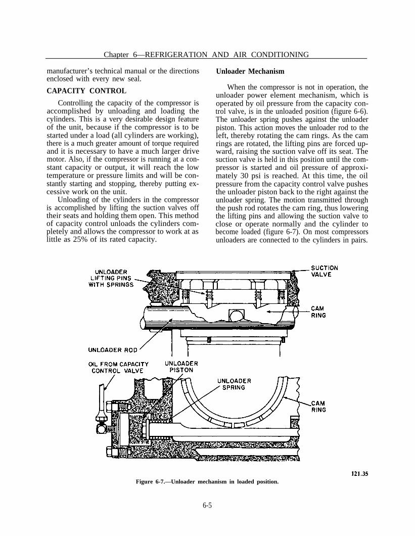
Chapter 6—REFRIGERATION AND AIR CONDITIONING
manufacturer’s technical manual or the directionsenclosed with every new seal.
CAPACITY CONTROL
Controlling the capacity of the compressor isaccomplished by unloading and loading thecylinders. This is a very desirable design featureof the unit, because if the compressor is to bestarted under a load (all cylinders are working),there is a much greater amount of torque requiredand it is necessary to have a much larger drivemotor. Also, if the compressor is running at a con-stant capacity or output, it will reach the lowtemperature or pressure limits and will be con-stantly starting and stopping, thereby putting ex-cessive work on the unit.
Unloading of the cylinders in the compressoris accomplished by lifting the suction valves offtheir seats and holding them open. This methodof capacity control unloads the cylinders com-pletely and allows the compressor to work at aslittle as 25% of its rated capacity.
Unloader Mechanism
When the compressor is not in operation, theunloader power element mechanism, which isoperated by oil pressure from the capacity con-trol valve, is in the unloaded position (figure 6-6).The unloader spring pushes against the unloaderpiston. This action moves the unloader rod to theleft, thereby rotating the cam rings. As the camrings are rotated, the lifting pins are forced up-ward, raising the suction valve off its seat. Thesuction valve is held in this position until the com-pressor is started and oil pressure of approxi-mately 30 psi is reached. At this time, the oilpressure from the capacity control valve pushesthe unloader piston back to the right against theunloader spring. The motion transmitted throughthe push rod rotates the cam ring, thus loweringthe lifting pins and allowing the suction valve toclose or operate normally and the cylinder tobecome loaded (figure 6-7). On most compressorsunloaders are connected to the cylinders in pairs.
Figure 6-7.—Unloader mechanism in loaded position.
6-5

ENGINEMAN 1 & C
Capacity Control Valve
The capacity control valve (figure 6-8) islocated in the compressor crankcase cover. Thevalve is actuated by oil pressure from the mainoil pump, and its function is to admit or relieveoil to or from the individual unloader powerelements, depending on suction or crankcasepressure. When the compressor is at rest the twocylinders equipped with the unloader element areunloaded and remain unloaded until the com-pressor is started and the oil pressure reaches nor-mal operating pressure.
As the high pressure oil from the pump enterschamber A of the capacity control valve andpasses through an orifice in the top of the pistonto chamber B, it forces the piston to the end ofits stroke against spring A. When the piston ofthe valve is forced against spring A, the circulargrooves which form chamber A are put in con-tact with the unloader connections. This admitshigh pressure oil to the unloader cylinder,actuating the unloader mechanism.
To control the oil pressure from the capacitycontrol valve, a capacity control regulatingneedle valve is installed. It is connected to thecrankcase and has an oil connecting line tochamber B of the capacity control valve. As thecrankcase, or suction pressure pulls downslightly below the setting of the regulating valve,the regulator needle valve opens and relieves theoil pressure from chamber B of the capacity con-trol valve. This permits spring A to push thecapacity control piston one step toward chamberB, uncovering the unloader connection nearest theend of the capacity control valve. This actionrelieves the oil pressure from the power elementand allows the power element spring to rotate thecam rings and unload the cylinder.
If the suction pressure continues to drop, theregulator needle valve relieves more oil pressureand more cylinders become unloaded. On theother hand, if the heat load increases, the suctionpressure increases, causing the regulating needlevalve to close and more cylinders to becomeloaded.
MAINTENANCE PRECAUTIONS
If a compressor cannot be pumped down andis damaged to the extent that it has to be opened
for repairs, it is necessary first to close the suc-tion and discharge valves and then following allsafety precautions, to allow all the refrigerant inthe compressor to vent to the atmosphere througha drain plug.
When it becomes necessary to remove, replace,or repair any internal parts of the compressor,observe the following precautions:
1. Carefully disassemble and inspect whileremoving all parts, noting their correct relativeposition so that errors will not be made whenreassembling.
2. Inspect all parts that become accessibleafter the removal of those parts requiring repairor replacement.
3. Make certain that all parts and surfaces arefree of dirt and moisture.
4. Apply clean compressor oil freely to allbearing and rubbing surfaces of the parts beingreplaced or reinstalled.
5. If the compressor is not equipped with anoil pump, make certain that the oil dipper on thelower connecting rod is in the correct position fordipping oil when the unit is in operation.
6. Position the ends of the piston rings so thatalternate joints come on the opposite side of thepiston.
7. Take care not to score the gasket surfaces.8. Renew all gaskets.9. Clean the crankcase and renew the oil
following correct procedures.
EVACUATING THE COMPRESSOR
In all but emergency situations it is desirableto evacuate the compressor with a vacuum pumprather than with the compressor itself. However,if you do not have a vacuum pump available, usethe following procedure:
1. Disconnect the connection in the com-pressor discharge gage line, between the dischargeline stop valve and the compressor.
2. Start the compressor and let it run until thegreatest possible vacuum is obtained.
3. Stop the compressor and immediately openthe suction stop valve slightly in order to blowrefrigerant through the compressor valves andpurge the air above the discharge valves throughthe open gage line.
6-6

Chapter 6—REFRGERATION AND AIR CONDITIONING
Figure 6-8.—Capacity control system.
6-7

4. Close the discharge gage line and open thedischarge line stop valve.
5. Remove all oil from the exterior of thecompressor, and test the compressor joints forleakage, using the halide leak detector.
CLEANING SUCTION STRAINERS
When putting a new unit into operation, thesuction strainers should be cleaned after a fewhours of operation. Refrigerants have a solventaction and will loosen any foreign matter in thesystem. This foreign matter will eventually reachthe suction strainers and after a few days of opera-tion, the strainers will need cleaning. Strainersshould be inspected frequently during the first fewweeks of plant operation, and then cleaned asfound necessary.
The suction strainers are located either in thecompressor housing or in the suction piping. Theprocedure for cleaning a strainer is as follows:
1.2.3.
4.
5.
6.
Pump down the compressor.Slowly bleed pressure from unit.Remove the strainer and inspect it forforeign matter.Clean the strainer screen by dipping it inan approved solvent and then allow it todry.Replace the strainer and evacuate the airfrom the compressor.Test the housing for leaks by wiping up alloil and then using a halide leak detector.
CONDENSERS
The compressor discharge line terminates atthe refrigerant condenser. In shipboard R-12installations, these condensers are usually of themultipass shell-and-tube type, with water cir-culating through the tubes. The tubes are ex-panded into grooved holes in the tube sheet soas to make an absolutely tight joint between theshell and the circulating water. Refrigerant vaporis admitted to the shell, and condenses on theouter surfaces of the tubes.
Any air or noncondensable gases which mayaccidentally enter the refrigeration system isdrawn through the piping and eventually dis-charged into the condenser with the R-12 gas. The
air or noncondensable gases accumulated in thecondenser are lighter than the refrigerant gas andrise to the top of the condenser when the plantis shut down. A purge valve, for purging therefrigeration system (when necessary), is installedeither at the top of the condenser, or at a highpoint in the compressor discharge line.
CLEANING CONDENSER TUBES
In order to clean the condenser tubesproperly, it is necessary first to drain the coolingwater from the condenser and then disconnect thewater connections and remove the condenserheads. When you remove the condenser heads,be careful not to damage the gaskets between thetube sheet and the water side of the condenserheads. Tubes should be inspected as often as prac-ticable and be cleaned when necessary, by usingany approved method. Use rubber plugs and anair or water lance when it is necessary to removeforeign deposits. Although it is essential that thetube surfaces be kept clear of particles of foreignmatter, care must be taken not to destroy the thinprotective coating on the inner surfaces of thetubes. When the tubes become badly corroded,they should be replaced in order to avoid thepossibility of losing the R-12 charge and admit-ting salt water into the R-12 system.
CLEANING AIR-COOLEDCONDENSERS
Although the large plants are equipped withwater-cooled condensers, the auxiliary units arecommonly provided with air-cooled condensers.The use of air-cooled condensers eliminates thenecessity for circulating water pumps and piping.
The exterior surface of the tubes and fins ona condenser should be kept free of dirt and anymatter that might obstruct heat flow and air cir-culation. Brush the finned surface clean with astiff bristle brush as often as necessary. Use lowpressure air to remove dirt in hard to reach placeson the condenser. When installations are exposedto salt spray and rain through open doors orhatches, take care to minimize corrosion of theexterior surfaces.
ENGINEMAN 1 & C
6-8

TESTING FOR LEAKS
To prevent serious loss of refrigerant throughleaky condenser tubes, test the condenser forleakage every week. Any condenser that has notbeen in use for the preceding 12 hours should alsobe tested.
To test for leaky condenser tubes, drain thewater side of the condenser and let stand for 12hours, then insert the exploring tube of the leakdetector through one of the drain plug openings.If this test indicates that R-12 gas is present, youneed to detect the exact location of the leak in thefollowing manner:
1. Remove the condenser heads.2. Clean and dry the tube sheets and the ends
of the tubes.3. Start at the top and work your way down
the tube sheet.4. Check both ends of each tube with a leak
detector.
Mark the tubes which show an indication ofleakage. If you cannot determine if the tube isleaking internally or around the tube sheet joint,plug the suspected tube with a cork or a similardevice and again check around the tube sheetjoint. Mark adjacent tubes, if necessary, to isolatethe suspected area.
5. To locate or isolate very small leaks in thecondenser tubes, hold the exploring tube at oneend of the condenser tube for about 10 secondsto draw fresh air through the tube. Then drivea cork in each end of the tube. Repeat this pro-cedure with all the tubes in the condenser. Allowthe condenser tubes to remain plugged for 4 to6 hours; then, remove the plugs one at a time andcheck each tube for leakage. If a leaky tube isdetected, replace the plug immediately to reducethe amount of refrigerant escaping. Makeappropriate repairs, or mark all leaky tubes forlater repairs.
RETUBING CONDENSERS
The general procedure for retubing condensersis outlined in Naval Ships’ Technical Manualchapter 516. The procedures are given in theapplicable manufacturer’s technical manual whena condenser of a specific type is being retubed.
CHECKING CONDENSERPERFORMANCE
An overall check for water-cooled condenserperformance may be used after, AND ONLYAFTER, the condenser has been properlypurged. After the condition of the condensing sur-face has been determined, prepare the system asoutlined in the procedure used to check for non-condensable gases discussed earlier in the chapter.Then proceed as follows:
1. While the compressor is in operation,record the condensing temperature which cor-responds to the pressure in the condenser.
2. Record the temperature of the water leav-ing the condenser.
3. Subtract the temperature of the water leav-ing the condenser from the condensingtemperature. (The temperature of the water leav-ing the condenser should be several degrees belowthe condensing temperature of pure R-12.)
4. If the difference between the temperatureof the water leaving the condenser and the con-densing temperature is 5° to 10°F above thetemperature difference obtained when the con-denser was in good condition and operating undersimilar heat loads, and if this difference is notcaused by an overcharge of refrigerant or non-condensable gases, clean the water side of thecondenser.
THERMOSTATIC EXPANSIONVALVES
When the thermostatic expansion valve isoperating properly, the temperature at the outletside of the valve is much lower than that at theinlet side. If there is no such temperature dif-ference when the system is in operation, the valveseat is probably dirty and clogged with foreignmatter.
Once a valve is properly adjusted, furtheradjustment should not be necessary. Any majortrouble can usually be traced to moisture or dirtcollecting at the valve seat and at the orifice.
TESTING AND ADJUSTMENT
Thermostatic expansion valves used in mostshipboard systems can be adjusted by means ofa gear and screw arrangement, (superheat to
Chapter 6—REFRIGERATION AND AIR CONDITIONING
6-9

adjustment), maintain a superheat rangingapproximately from 4° to 12 °F at the cooling coiloutlet. The proper superheat adjustment varies,of course, with the design and the serviceoperating conditions of the valve, and the designof a particular plant. Increased spring pressureincreases the degree of superheat at the coil outlet;decreased pressure on the other hand, has theopposite effect. Many thermostatic expansionvalves are initially adjusted by the manufacturerto maintain a predetermined degree of superheat,and no provisions are made for further ad-justments in service.
When the expansion valves are adjusted to givea high degree of superheat at the coil outlet, orwhen a valve is stuck shut, the amount ofrefrigerant admitted to the cooling coil is reduced.With an insufficient amount of refrigerant, thecoil is “starved” and operates at a reduced capac-ity. Compressor lubricating oil carried with therefrigerant tends to collect at the bottom of thecooling coils, thus robbing the compressorcrankcase, and providing a condition wherebyslugs of lubricating oil are drawn back to the com-pressor. If an expansion valve is adjusted for toolow a degree of superheat, or if the valve is stuckopen, the liquid refrigerant may flood from thecooling coils back to the compressor. Should theliquid refrigerant collect at a low point in the suc-tion line or coil, and be drawn back to the com-pressor intermittently in slugs, there will be dangerof injury to the moving parts of the compressor.
In general, the expansion valves for air con-ditioning and water cooling plants (hightemperature installations) are adjusted for highersuperheat than the expansion valves for coldstorage refrigeration and ship’s service storeequipment (low temperature installations).
If it is impossible to adjust expansion valvesto the desired settings, or if it is suspected thatthe expansion valve assembly is defective and re-quires replacement, make appropriate tests. (Firstmake sure that the liquid strainers are clean, thatthe solenoid valves are operative, and that thesystem is sufficiently charged with refrigerant.)
The major equipment required for expansionvalve tests is as follows:
1. A service drum of R-12, or a supply ofclean dry air at 70 to 100 psig. The service drum
is used to supply gas under pressure. The gasused does not have to be the same as thatemployed in the thermal element of the valve be-ing tested.
2. A high pressure and a low pressure gage.The low pressure gage should be accurate and ingood condition so that the pointer does not haveany appreciable lost motion. The high pressuregage, while not absolutely necessary, is useful inshowing the pressure on the inlet side of the valve.Normally, refrigeration plants are provided withsuitable replacement and test pressure gages.
The procedure for testing is as follows:
1. Connect the valve inlet to the gas supplywith the high pressure gage attached to indicatethe gas pressure to the valve, and the low pressuregage loosely connected to the expansion valveoutlet. The low pressure gage must be connectedup loosely so as to provide a small amount ofleakage through the connection.
2. Insert the expansion valve thermal elementin a bath of crushed ice. Do not perform this testwith a container full of water in which only a smallamount of crushed ice is floating.
3. Open the valve on the service drum or inthe air supply line. Make certain that the gassupply is sufficient to build up the pressure to atleast 70 psi on the high pressure gage.
4. Adjust the expansion valve, if it is desiredto adjust for 10°F superheat, the pressure on theoutlet gage should be 22.5 psig. This pressure isequivalent to the pressure of an R-12 evaporatingtemperature of 22°F. Since the ice maintains thebulb at 32°F, the valve adjustment is for 10°Fsuperheat (difference between 32 and 22). For a5 °F superheat adjustment, the valve should beadjusted to give a pressure of approximately26.1 psig. Allow for a small amount of leakagethrough the low pressure gage connection whilethis adjustment is being made.
5. To determine if the valve operatessmoothly, tap the valve body lightly with a smallweight. The low pressure gage needle should notjump more than 1 psi.
6. Tighten the low pressure gage connectionand stop the leakage at the joints. Determine ifthe expansion valve seats tightly. If the valve isin good condition, the pressure will increase a fewpounds and then either stop or build up very
ENGINEMAN 1 & C
6-10

Chapter 6—REFRIGERATION AND AIR CONDITIONING
slowly. If the valve is leaking, the pressure willbuild up rapidly until it equals the inlet pressure.
7. Again loosen the gage to permit leakage atthe gage connections. Remove the thermal ele-ment, or control bulb, from the crushed ice andwarm it with the hand or place it in water thatis at room temperature. The pressure shouldincrease rapidly, showing that the power elementhas not lost its charge. If there is no increase inpressure, the power element is dead.
8. With high pressure showing on both gagesas outlined above, the valve can be tested to deter-mine whether the body joints or the bellows leak.This can be done by using a halide leak detector.When performing this test, it is important thatthe body of the valve have a fairly high pressureapplied to it. In addition, the gages and other fit-tings should be made up tightly at the joints soas to eliminate leakage at these points.
present in various combinations in the compound.You may be more familiar with their brand ortrademark names such as: Freon(s), Gentron,Genesolv D, Frigen, AFFF, or carbontetrachloride. As Enginemen, we work with theserefrigerants, solvents, and fire extinguishing com-pounds regularly aboard ship. The extended androutine usage of halocarbons in the military andcivilian environments (e.g., home/car air condi-tioners) has led us to a false sense of security whichmakes us forget the inherent poisonous nature ofhalocarbons, particularly when used in high con-centrations in enclosed or confined spaces.
REPLACEMENT OF A VALVE
When an expansion valve is defective, it mustbe replaced. Some valves used on naval ships havereplaceable assemblies and it is possible to replacea faulty power element or other part of the valvewithout having to replace the entire assembly.When replacement of an expansion valve isnecessary, replace the unit with a valve of the samecapacity and type.
Warnings, hazards, and cautions in technicaland training publications are usually benign. Thelabeling of containers and storage areas are con-sistently inadequate. The procedures for thedisposal of halocarbon waste are not well knownnor are they followed. Most people do not knowthe physiological effects of high concentrationsof halocarbons on humans or the recommendedfirst aid by both medical and non-medicalpersonnel.
ADDITIONAL SYSTEMMAINTENANCE
In addition to the maintenance of the com-ponents described above, there are other parts ofthe system that will need periodic maintenance tokeep the plant operating properly.
Vibration may cause leakage in the pipingsystem, allowing air and moisture to be drawn inor there may be a loss of the refrigerant charge.If this happens, the plant will operate erraticallyand inefficiently until the cause of trouble iscorrected.
All Enginemen who handle or use halocarbonsmust be aware of the hazardous properties ofhalocarbons. The greatest hazards have beenassociated with Freon 113 refrigerant andGenetron 113 (a fluorocarbon compound), withthe chemical name of TRICHLOROTRI-FLUOROETHANE, which is used in large quan-tities for cleaning refrigeration, hydraulic, air andoxygen systems, and as a solvent for removing oiland grease from machinery. Trichlorotri-fluoroethane is a heavy, colorless liquid at roomtemperature, and has an odor similar to dryclean-ing fluid. Because of its low boiling-point itevaporates rapidly at room temperature. Its vaporis several times heavier than air and tends to col-lect in low places.
HALOCARBON SAFETY
Halocarbons are organic chemical compoundscontaining one or more atoms of carbon andhydrogen plus one or more atoms of fluorine,bromine, chlorine, or iodine which may be
Trichlorotrifluoroethane should always betreated as a toxic solvent. Exposure to it can causeheadache, rapid heartbeat, light-headedness, andtingling of fingers or toes. Any of these symptomsis a warning to leave the area immediately. Inhigher concentrations the solvent has an anestheticeffect (causing uncoordination and stumbling); itcan effect the heartbeat (causing irregular beatsor even stoppage) and can cause tremors, convul-sions, and DEATH. Refrigerant gases such asFreon 12 and 22 have properties similar to the
6-11

ENGINEMAN 1 & C
ones described above except that they are practic-ally odorless and can cause freeze burns.
During all primary maintenance or industrialuses of halocarbons such as flushing or recharg-ing refrigeration or air conditioning systems, thefollowing “good engineering” precautions aremandatory:
7. A medical department representative, whois trained and knowledgeable in the physiologicaleffects, prescribed first aid and emergency treat-ment methods for halocarbon mishaps, should bealerted to the maintenance action being performedand standing by for quick response.
1. Strict compliance with NSTM gas-freeEngineering directions for entry into enclosed orconfined spaces, and close adherence to standardoperating procedures for all halocarbonmaintenance actions.
8. An emergency eyewash/shower system inthe immediate vicinity of all halocarbon opera-tions should its use be required. Where a perma-nent system is not available, a portable system of5-10 gallon capacity should suffice. Only potablewater should be utilized for this purpose.
2. Tested and operational ventilation systems.Availability of portable equipment to provide in-take from—and exhaust to the atmosphere (notrecirculation) sufficient to maintain halocarbonconcentration at acceptable limits throughout thewhole maintenance action. (Example: The limitfor continuous exposure to the vapors of Freon113 is 1000 parts of solvent per million parts ofair. This limit will be reached by evaporation ofapproximately 100 milliliters (less than 1/2 cup)of solvent in a 10 × 10 × 10 ft. space). Localexhaust ventilation capable of maintaining aminimum capture velocity of 100 fpm over theface of the container or operation is normallyrequired in order to maintain the vapor within ac-ceptable limits. Note: Absolutely NO venting ofhalocarbons below decks shall be permitted.
9. Ship’s emergency rescue teams (e.g.,“Flying Squads” and repair parties) familiar withthe hazards of halocarbons and trained in air-supplied respirator requirements when involvedin halocarbon rescue operations.
10. The performance of hot work is pro-hibited from halocarbon work areas, due to thepotential decomposition of halocarbons into moretoxic chemicals.
As stated earlier, in high concentrations,halocarbons are toxic chemicals. Any handling orusage of these chemicals requires the followingminimum personal protective measures:
3. Positive pressure emergency breathingdevices with supplied air available in the space forinstant donning and egress in the event of ahalocarbon mishap.
1.
2.3.4.5.
Full-length face shield or chemical workersgogglesApron or coveralls (both may be required)Elbow length glovesBoots or bootiesClothing and equipment must be im-pervious and resistant to halocarbons.
4. Established two-way communications be-tween the halocarbon pump at the bulk source andthe equipment being filled, cleaned, or flushed.A backup sound powered system is recommended.
Note: Non-impervious clothing whichbecomes wet with halocarbons must beimmediately removed and not reworn until alltraces of the chemical are removed by cleaning.
5. Verification of filling and flushing systemintegrity by leak testing (e.g., a pressure drop test)before halocarbon operations commence.
CHARGING THE SYSTEM
6. A minimum of two people should be sta-tioned in the space, with a safety observer (tender)in the vicinity of the egress route if available.Rescue equipment (as necessary) to quicklyremove personnel from the space in the event ofan emergency. (Rescue personnel should also beequipped with protective clothing and positivepressure respiratory protection.)
Information concerning the charging ofrefrigeration systems may be found in NavalShips’ Technical Manual chapter 516. The amountof refrigerant charge must be sufficient to main-tain a liquid seal between the condensing and theevaporating sides of the system. When the com-pressor stops, under normal operating conditions,the receiver of a properly charged system is about85% full of refrigerant. The proper charge for a
6-12

Chapter 6—REFRIGERATION AND AIR CONDITIONING
specific system or unit can be found in themanufacturer’s technical manual or on the ship’sblueprints.
A refrigeration system should not be chargedif there are leaks or if there is reason to believethat there is a leak in the system. The leaks mustbe found and corrected. A system should bechecked for leaks immediately following—orduring—the process of charging.
A refrigeration system must have an adequatecharge of refrigerant at all times; otherwise itsefficiency and capacity will be impaired.
PURGING THE SYSTEM
To determine if there are noncondensablegases in the system, close the liquid line stopvalve. By-pass all evaporator pressure regulatorvalves and allow the system to pump down oneor more times. Stop the compressor. By-pass thewater regulating valve and circulate cooling waterthrough the condenser. When discharge pressurestops dropping, convert the pressure totemperature and from this subtract thetemperature of the injection or overboard. (Theyboth should be equalized.) A variation of over 5 °Fwill indicate that air and noncondensable gasesare present in the system. Crack open the purgevalve for 2-3 seconds at 2 to 3 minute intervalsuntil the temperature is within 5 °F.
CLEANING LIQUIDLINE STRAINERS
Where a liquid line strainer is installed, itshould be cleaned at the same intervals as the suc-tion strainer. If a liquid line strainer becomesclogged to the extent that it needs cleaning, a lossof refrigeration effect will take place. Thetubing on the outlet side of the strainer will bemuch colder than the tubing on the inlet side.
To clean the liquid line strainer, secure thereceiver outlet valve and wait a few minutes toallow any liquid in the strainer to flow to the cool-ing coils. Close the strainer outlet valve and verycarefully loosen the cap which is bolted to thestrainer body. (Use all appropriate safety gear.)When all of the pressure is bled out of the strainer,remove the cap and lift out the strainer screen.Clean the strainer screen with a small brush,using an approved solvent. Reassemble the spring
and screen in the strainer body. Replace thestrainer cap loosely. Purge the air out of thestrainer, by blowing refrigerant through it, thentighten the cap. After assembly is complete, testthe unit for leaks.
CLEANING OIL FILTERSAND STRAINERS
Compressors arranged for forced feed lubrica-tion are provided with lubricating oil strainers inthe suction line of the lube oil pump and an oilfilter installed in the pump discharge line. Agradual decrease in lubricating oil pressure in-dicates that the units need cleaning. Cleaning isaccomplished in much the same manner asdescribed for cleaning suction strainers.
When cleaning is necessary, the lubricating oilin the crankcase should be drained from the com-pressor and a new charge of oil, equal to theamount drained, should be added before re-starting the unit. When the compressor is put backinto operation, the lube oil pressure must beadjusted to the proper setting by adjustment ofthe oil pressure regulator.
MAINTAINING COOLING COILS
Cooling coils should be inspected regularly andcleaned as required. The cooling coils should bedefrosted as often as necessary to maintain theeffectiveness of the cooling surface. Excessivebuild up of frost on the cooling coils will resultin reduced capacity of the plant, low compressorsuction pressure, and a tendency for the com-pressor to short-cycle. The maximum time inter-val between defrosting depends on such factorsas refrigerant evaporating temperature, conditionof door gaskets, moisture content of suppliesplaced in boxes, how frequently the doors areopened and atmospheric humidity.
Cooling coils should be defrosted before thefrost thickness reaches three-sixteenths of an inch.When defrosting, do not scrape or break off thefrost, as this may cause damage to the coils.
EVACUATING AND DEHYDRATINGTHE SYSTEM
The major cause of system failures is moisture(H2O) which is brought in through air leaks.
6-13

When H2O combines with R- 12 it forms sulfricacid which will attack the entire system. Goodengineering practice dictates that evacuation,dehydration and fixing all air leaks will in the longterm prevent an acid attack upon the system.
evacuation process. If possible, the dehydratedair should be heated to about 240°F.
Large dehydrators, suitable for preliminarydehydration of refrigeration systems, are usuallyavailable at naval shipyards and aboard tendersand repair ships.
Where moisture accumulation must be cor-rected, the system should first be cleared ofrefrigerant and air. The time required for theseprocesses will depend upon the size of the systemand the amount of moisture present. It is goodengineering practice to circulate heated airthrough a large dehydrator for several hours,or as long as the dehydrator drying agentremains effective, before proceeding with the
After the preliminary dehydration, the remain-ing moisture is evacuated by means of a two-stagehigh-efficiency vacuum pump. (These vacuumpumps are available aboard tenders and repairships.)
A vacuum indicator (figure 6-9) is attached tothe two-stage high efficiency pump. It consists ofan insulated test tube containing a wet bulb ther-mometer with its wick immersed in distilled water.This indicator is connected to the vacuum pumpsuction line, which in turn, is connected to therefrigeration system. The refrigerant circuit shouldbe closed to the atmosphere and the charging con-nection should be opened to the vacuum pump.
Two-stage pumps are started for operation inPARALLEL so that maximum displacement maybe obtained during the initial pump-down stages.When the indicator shows a temperature of about55 °F (0.43 inch Hg, absolute), the pumps areplaced in SERIES operation (wherein thedischarge from the first step enters the suction ofthe second step pump). The dehydration processwill be reflected in the temperature drop of thevacuum indicator (as shown in figure 6-10).Readings will initially reflect ambienttemperatures. Then they will show rapidly
Figure 6-10.—Vacuum indicator readings plotted duringFigure 6-9.—Dehydrator vacuum indicator. dehydration.
ENGINEMAN 1 & C
6-14

Chapter 6—REFRIGERATION AND AIR CONDITIONING
falling temperatures until the water in the systemstarts to boil.
When most of the evaporated moisture hasbeen evacuated from the system, the indicator willshow a decrease in temperature. As soon as thetemperature reaches 35 °F (0.2 inch Hg, absolute),admit dry air through a chemical dehydratorinto the system at a point farthest from the pump.As the pump continues operating, the dry air willmix with and dilute any remaining moisture.Secure the opening which feeds the dry air to thesystem. The system must continue evacuating untilthe indicator again shows a temperature of 35 °F.At this time, the dehydration process is complete.Close the valves and disconnect the vacuumpump.
as activated alumina and silica gel. However,when special drying agents are employed theyshould be reactivated in accordance with thespecific instructions furnished by themanufacturer.
After reactivation, the drying agent should beplaced back in the dehydrator shell and sealed asquickly as possible, in order to prevent absorp-tion of atmospheric moisture. When the dryingagent becomes fouled or saturated with lubricatingoil, it must be replaced with a fresh charge, orwith a dehydrator cartridge, taken from a sealedcontainer.
Sometimes it is impossible to obtain atemperature as low as 35 °F in the vacuumindicator. The probable reasons for this and thecorrective procedures to take, are as follows:
1. Excess moisture is present in the system.Because of the acid being formed, the dehydra-tion procedure should be conducted for longerperiods.
Remember that the dehydrators that arepermanently installed in refrigeration systems ofnaval ships are designed to remove only theminute quantities of moisture unavoidablyintroduced in the system. Extreme care must betaken to prevent moisture, or moisture-laden air,from entering the system.
CLEANING THE SYSTEM
2. Absorbed refrigerant is present in thelubricating oil contained in the compressorcrankcase. Remove the lubricating oil from thecrankcase before proceeding with the dehydrationprocess.
3. Air is leaking into the system. The leakmust be found and stopped. It will be necessaryto repeat the procedure required for detectingleaks in the system.
4. Inefficient vacuum pump or defectivevacuum indicator. The defective unit(s) should berepaired or replaced.
Systems may accumulate dirt and scale as aresult of improper procedures used during repairor installation of the system. If such dirt isexcessive and a tank-type cleaner is available, con-nect the cleaner to the compressor suction strainer.Where such a cleaner is not available, insert a hardwool felt filter, about 5/16 inch thick, in the suc-tion strainer screen. The plant should then beoperated with an operator in attendance, for atleast 36 hours or until cleaned, depending uponthe size and the condition of the plant.
Immediately after each period of use, or afterthe system has been opened for repairs, the dry-ing agent in the dehydrator should be replaced.If a replacement cartridge is not available, the dry-ing agent can be reactivated and used until areplacement is available.
AIR CONDITIONING CONTROL
Reactivation is accomplished by removing thedrying agent and heating it, for 12 hours, at atemperature of 300°F to bake out the moisture.The drying agent may be placed in an oven, ora stream of hot air may be circulated through thecartridge. These methods are satisfactory for reac-tivating commonly used dehydrating agents such
Most of the information presented to thispoint applies to the refrigeration side of a system,whether it is used for a refrigeration plant or forair conditioning. The compressor controls forboth type systems are nearly identical, however,the devices used to control space temperatures dif-fer. A two-position control, sometimes called theon/off control, is used for the automatic controlof most shipboard air conditioning systems.
6-15

ENGINEMAN 1 & C
TWO-POSITION CONTROL
This control may be used on three types ofsystems:
1. Systems employing a simple thermostatic-ally controlled single-pole switch to control flowof refrigerant to the cooling coil.
2. Systems using reheaters, employing a ther-mostatic element actuating two interlockedswitches.
3. Systems using reheaters in the same man-ner as in item 2 with control of humidity added,where specified.
The type 1 system above is the most commonlyused and requires little explanation. A thermostat,consisting of a temperature sending element,actuating a single-pole, single-throw switch, opensand closes a magnetic valve to start and stop theflow of refrigerant—chilled water or commercialrefrigerant. This type of control is similar to ther-mostatic control for the refrigeration plant.Although the type 1 system requires single-polethermostats, the 2PD used in type 2 and type 3systems can be used. The cooling switch wouldthen be connected in the normal manner with theheating switch inoperative.
The use of the type 2 system has greatly in-creased, due to the present effort to make living
and working spaces more comfortable and to therapid development of various types of weaponssystems. Such spaces often use a common cool-ing coil serving several different spaces. Assumethat three spaces are being cooled by a commoncoil. Since the load changes seldom occursimultaneously, electric or steam reheaters areinstalled in the cooling air ducts and the coolingthermostats of the various spaces are connectedin parallel so that any one may open the coolingcoil valve.
Suppose space “B” (figure 6-11) has a loadchange and spaces “A” and “C” do not. Thesespaces would become too cold for comfort withthe coil operating to take care of space "B". Inorder to prevent this condition, the thermostatwould close the heating switch and energize thereheaters for spaces A and C.
The type 3 system is identical to the type 2system, except that a humidistat is wired inparallel with the thermostatic heating switch. Thistype system is used mostly in weapons and elec-tronic spaces. The humidistat is set for the relativehumidity condition desired. In most installations,it is only necessary to prevent the humidity fromexceeding 55%. Where the humidistat is installed,an increase in temperature beyond the thermostatsetting will close the thermostat cooling switch andan increase in relative humidity beyond the
Figure 6-11.—Typical air conditioning system.
6-16

Chapter 6—REFRIGERATION AND AIR CONDITIONING
humidistat setting will close the heating switch,energizing the reheaters.
MAINTENANCE
Proper attention to maintenance checks willoften allow you to detect developing troubles intime to take corrective action. Since mostbreakdowns often occur at the most inopportunetime, periodic checks and maintenance willprove to be well worthwhile to avoidmalfunctions.
The two-position control system can easily bechecked out in a reasonably short time. Thecheckout period should be at least every threemonths or more often if it proves to be necessary.Inspection and checks should be conducted at thebeginning of the cooling season and about mid-way. The same should be done for the heatingseason.
Sensing elements should be inspected and anydust accumulations removed. Thermostaticsensing elements should have dust and dirt re-moved with a soft brush, and the sensing elementsin humidistats should be blown off gently withair so as not to damage the elements.
Magnetic valves should be checked for opera-tion. Be sure that the valves are opening and clos-ing completely.
Setpoints of the thermostats and humidistatsshould be checked with a calibrated thermometerand a reliable humidity indicator.
When servicing the two-position controlsystem there are three possible areas where trou-ble may occur:
1. The sensing element and its associatedmechanism.
2. The magnetic valves that control the flowor refrigerant.
3. The wiring system which connects the sen-sing elements to the solenoids of the magneticvalves and the controller of the electric heaters.
DETECTING ANDCORRECTING TROUBLES
Faulty operation of the refrigerating and airconditioning plants is indicated by various definitesymptoms. Information in figures 6-12 and 6-13indicates some possible troubles that may be en-countered, the possible causes of these troubles,and the corrective action which may be taken. Butremember always consult the manufacturer’stechnical manual before attempting any repair oradjustment on your equipment.
6-17

ENGINEMAN 1 & C
Trouble Possible Cause Corrective Measure
High condensing pressure. Air or non-condensable gasin system.
Purge air from condenser.
Inlet water warm. Increase quantity of con-densing water.
Insufficient water flowingthrough condenser.
Increase quantity of water.
Condenser tubes clogged orscaled.
Clean condenser water tubes.
Too much liquid in receiver,condenser tubes submergedin liquid refrigerant.
Draw off liquid into servicecylinder.
Low condensing pressure. Too much water flowingthrough condenser.
Reduce quantity of water.
Water too cold. Reduce quantity of water.
Liquid refrigerant floodingback from evaporator.
Change expansion valveadjustment, examinefastening of thermal bulb.
Leaky discharge valve. Remove head, examine valves.Replace any found defective.
High suction pressure. Overfeeding of expansionvalve.
Leaky suction valve.
Regulate expansion valve,check bulb attachment.
Remove head, examine valveand replace if worn.
Low suction pressure. Restricted liquid line andexpansion valve or suctionscreens.
Pump down, remove, examineand clean screens.
Insufficient refrigerant in Check refrigerant chargesystem.
Too much oil circulatingin system.
Check for too much oil incirculation. Remove oil.
Improper adjustment ofexpansion valves.
Adjust valve to give moreflow.
Expansion valve powerelement dead or weak.
Replace expansion valvepower element.
Figure 6-12.—Trouble diagnosis chart.
6-18
54.299.1

Chapter 6—REFRIGERATION AND AIR CONDITIONING
Trouble
Compressor short cycles onlow pressure control.
Compressor runs continuously.
Compressor short cycles onhigh pressure control switch.
Compressor will not run.
Possible Cause
Low refrigerant charge.
Thermal expansion valve notfeeding properly.
(a) Dirty strainers.
(b) Moisture frozen in orificeor orifice plugged withdirt.
(c) Power element dead orweak.
Water flow throughevaporators restricted orstopped. Evaporator coilsplugged, dirty, or cloggedwith frost.
Defective low pressurecontrol switch.
Shortage of refrigerant.
Leaking discharge valves.
Insufficient water flowingthrough condenser, cloggedcondenser.
Defective high pressurecontrol switch.
Seized compressor.
Cut-in point of low pressurecontrol switch too high.
High pressure control switchdoes not cut-in.
1. Defective switch.
2. Electric power cut off.
2. Service or disconnectswitch open.
Corrective Measure
Locate and repair leaks.Charge refrigerant.
Adjust, repair or replacethermal expansion valve.
(a) Clean strainers.
(b) Remove moirture or dirt(Use system dehydrator).
(c) Replace power element.
Remove restriction. Checkwater flow. Clean coilsor tubes.
Repair or replace low pres-sure control switch.
Repair leak and rechargesystem.
Replace discharge valves.
Determine if water has beenturned off. Check for scaledor fouled condenser.
Repair or replace highpressure control switch.
Repair or replace compressor.
Set L. P. control switch tocut-in at correct pressure.
Check discharge pressureand reset H. P. controlswitch.
1. Repair or replace switch.
2. Check power supply.
3. Close switches.
54.299.2
Figure 6-12.—Trouble diagnosis chart—Continued.
6-19
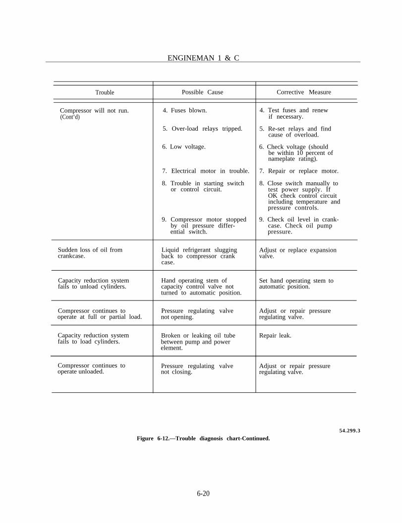
ENGINEMAN 1 & C
Trouble
Compressor will not run.(Cont‘d)
Sudden loss of oil fromcrankcase.
Possible Cause
4. Fuses blown.
5. Over-load relays tripped.
6. Low voltage.
7. Electrical motor in trouble.
8. Trouble in starting switchor control circuit.
9. Compressor motor stoppedby oil pressure differ-ential switch.
Liquid refrigerant sluggingback to compressor crankcase.
Capacity reduction systemfails to unload cylinders.
Hand operating stem ofcapacity control valve notturned to automatic position.
Compressor continues tooperate at full or partial load.
Pressure regulating valvenot opening.
Capacity reduction systemfails to load cylinders.
Broken or leaking oil tubebetween pump and powerelement.
Compressor continues tooperate unloaded.
Pressure regulating valvenot closing.
Corrective Measure
4. Test fuses and renewif necessary.
5. Re-set relays and findcause of overload.
6. Check voltage (shouldbe within 10 percent ofnameplate rating).
7. Repair or replace motor.
8. Close switch manually totest power supply. IfOK check control circuitincluding temperature andpressure controls.
9. Check oil level in crank-case. Check oil pumppressure.
Adjust or replace expansionvalve.
Set hand operating stem toautomatic position.
Adjust or repair pressureregulating valve.
Repair leak.
Adjust or repair pressureregulating valve.
54.299.3
Figure 6-12.—Trouble diagnosis chart-Continued.
6-20

Chapter 6—REFRIGERATION AND AIR CONDITIONING
TEST REMEDYTROUBLE POSSIBLECAUSE
Relocate thermostat toa place more repre-sentative of averagespace temperature.
Space temperaturehigher than thermostatsetting and thermostatcontacts are open.
B a d l o c a t i o n o fthermostat.
Carefully read tempera-ture at the sensingelement.
Thermostat out of ad- Calibrate with good C l e a n , a d j u s t , o rjustment or sticking. thermometer. replace the thermostat.
Cooling coil magneticvalve not opening.
Solenoid Valve.Valve sticking.
Replace solenoid coil.Clean valve or adjustpilots.
Space temperaturethermostat lower thanthermostat setting andcontacts are closed.
Bad location of ther-mostat (this will also ef-fect cooling).
Test with reliable ther- Move thermostat to amometer at location. better location.
Space temperaturelower than thermostatsetting and thermostatcontacts are open.
Cooling coil magneticvalve stuck in openposition.
Stuck valve. Disassemble and clean.
Replace solenoid coil.Clean the valve.
Heating coil magneticvalve stuck or badsolenoid.
Test solenoid.Test valve.
Thermostat or humidi-stat time constant toolow, causing widedeviation from setpoint.
Sensing element fouledwith lint and dirt.
Examine. Clean.
Electric heater does not Controller contacts Use test lamp tocut out. stuck. determine.
Replace contac ts ,springs or other parts asfound defective.
Electric heater does not Overheat protectioncut in. not reset or defective.
Place test lamp across. Repair or replace.
Figure 6-13.—Trouble diagnosis chart.
6-21

CHAPTER 7
AUXILIARY MACHINERY
Information related to much of the auxiliarymachinery aboard ship is provided in Engineman3 & 2, NAVEDTRA 10541 (current revision).This chapter provides additional information onthe care and maintenance of compressed airsystems and equipment, auxiliary boilers,hydraulic systems, distilling plants and pressurevalves.
COMPRESSED AIR SYSTEMS
Qualifications for lower rates require that youknow not only the purpose and principles in-volved, but also the operation and performanceof routine maintenance on many auxiliary systemsand units which use compressed air. As an EN,you have already used compressed air for suchjobs as starting diesel engines, blowing out andcleaning various units, and operating numerouspneumatic tools. When working with any of thethree types of compressed air systems (low,medium, and high pressure), you have probablyfound that the principal source of many troublesis to be found in the compressor. Even thoughthe design and capacity of compressors vary, themaintenance procedures are essentially the samefor all of them. However, the care andmaintenance of high pressure compressors requireadditional safety precautions and adherence toprocedures recommended by the manufacturer.
Because of your past experience, parts of thefollowing discussion will serve only as a review,while other portions of the discussion will benefityou in your study for advancement, and will behelpful when you are called upon to train others.
To avoid unnecessary damage to equipment,always use proper tools and take all necessaryprecautions. The correct use of proper tools
should be kept constantly in mind when a machineof any kind is being serviced. Remember, the im-proper use of tools and methods may cause seriouscasualties to both machinery and personnel.
Although rugged and dependable, modernauxiliary machinery is not designed to withstandabusive treatment. Gasketed joints, pipe joints,and bolts are designed to safely withstand thestrain required for a tight connection when thespecified torque is applied with the correct tool.Whenever a joint or bolt cannot be tightenedwithout the use of an oversized wrench or wrenchhandle extension, there is usually somethingwrong with the assembly.
Pounding on a wrench to acquire additionalforce usually results in damage to the equipment.Use of a wrench extension is likely to distort thegasketed surface or twist off the bolt withoutachieving a tight joint. The application of anyforce in excess of the force prescribed usuallyresults in breakage.
CARE AND MAINTENANCE OFAIR COMPRESSORS
To keep the ship’s air compressors operatingefficiently at all times and to prevent as manytroubles as possible, it is necessary to know howto care for air intakes and filters; how to main-tain and replace air valves; how to take care ofair cylinders, pistons, and wrist pins; how toadjust bearings and couplings; and how toproperly maintain the lubrication, the cooling, thecontrol, and the air systems.
Air Intakes andIntake Filters
The satisfactory operation of any compressoris based on a supply of clean, cool, dry air. To
7-1
ENGINEMAN 1 & C
aid in keeping the air supply clean, filters arefitted to compressor intakes. Unless inspected andcleaned regularly, these filters become clogged andcause a loss of capacity.
Filter elements should be removed from theintake and cleaned either with a jet of hot wateror steam, or by immersion in a strong solutionof sal soda. The filter body should be drained andreplaced. Filter elements of the oil-wetted typeshould be dipped in a clean, medium viscosity oilafter cleaning and the excess oil should bedrained from the elements before replacing themon the filter intakes. Gasoline or kerosene shouldnot be used for cleaning air filters because of theexplosive fumes which may collect in the com-pressor or air receiver.
Dehydrators
On some ships, compressed air is used for theoperation of missile system components and withautomatic controls for boilers. In order to pre-vent failure of these systems, moisture andlubricants from the compressor must be kept ata minimum. Blowing down the compressorseparators prevents most of this, but still somemoisture is carried over.
To aid in the removal of the moisture andlubricants, two types of dehydrators are gener-ally used: type I refrigerant dehydrators and typeII dehydrators using a desiccant of either silicagel or activated alumina, and containing electricheating coils for reactivating the desiccant whenit becomes saturated with moisture. Type IIdehydrators are normally installed in pairs so thatone can always be in service while the other is be-ing reactivated.
Air Valves
Air inlet and discharge valves are vital partsof a compressor and should receive careful atten-tion. When these valves leak, the compressorcapacity is reduced and results in an unbalancedstage pressure.
There are several symptoms which signify thatan air valve is not functioning properly. A devia-tion from normal intercooler pressure mayindicate a leaking or broken valve. A defectiveinlet valve above the intercooler will cause a risein pressure in the intercooler, while a defective
7-2
discharge valve below the intercooler will causea decrease in the intercooler pressure. An unusu-ally hot valve cover is a sign of valve trouble.
Dirt is generally the cause of leaking valves.The source of valve trouble can usually be tracedto dirty intake air; the use of excessive or impropercylinder oil; or excessively high air temperature,resulting from faulty cooling. A periodic inspec-tion and cleaning of valves and valve passages willminimize and perhaps prevent the occurrence ofair valve troubles. The frequency for cleaningvalves must be determined for each installation.
The air valves are easily accessible and areremoved by first loosening the valve cover plates.Then the valve and valve unloader, if installed,may be lifted out. Each valve should be markedso that it may later be returned to the same open-ing from which it was removed.
Dirt or carbon can usually be removed fromvalve parts without disassembling the valve. Ifdisassembly is necessary, notice should be takenon how the various parts are arranged so that theproper relationship will be kept when the valveis reassembled. To remove carbon from valveparts, soak each part in kerosene and then brushor scrape lightly. After drying and reassemblingthe valve parts, test the valve action to be surethat the valve opens and closes freely.
Before air valves are replaced in a cylinder,inspect the gaskets. If the gaskets are made ofmaterials other than copper, and are damaged,change them. Copper gaskets should always bereplaced. Since it is often difficult to distinguishbetween suction and discharge valves, use extremecare when inserting valves in the cylinder. Makesure that suction valves open TOWARD, anddischarge valves AWAY FROM, the center of thecylinder. Otherwise, serious damage or loss ofcapacity will result. If special locknuts are not pro-vided to seal against leakage at the threads of thevalve setscrew, place a turn of solder or fuse wirearound the screw and set down into a recess bythe locking nut.
Cylinders and Pistons
When you find that it is necessary to inspectthe cylinders or pistons of an air compressor, youshould refer to the manufacturer’s instructionmanual and the appropriate Planned MaintenanceSystem (PMS) maintenance requirement card

Chapter 7—AUXILIARY MACHINERY
(MRC) for the proper methods and tools requiredfor removing the heads. The following is generalinformation on removing a piston, fitting newpiston rings, and checking piston end clearancefor a vertical compressor.
To remove trunk pistons from vertical com-pressors, it is first necessary to remove the cylinderheads. In the case of three- or four-stage com-pressors, the third and fourth stage cylinders willalso have to be removed. Next, you must turn thecompressor by hand to top center and remove thelower half of the crank pin bearing, or the entirecrank pin bearing box, if so directed. Pull up thepiston and connecting rod through the cylinder.In removing pistons from compressors fitted withcross heads and piston rods, the general procedureis to loosen the piston rod locknuts adjacent tothe cross head, then unscrew the piston rod fromthe cross head and lift the piston and the rod outof the cylinder.
If the piston rings are worn or broken andrequire replacement, take accurate measurementsof the cylinder or liner to determine the exactdiameter. Standard size rings may be used in over-size cylinders if the oversize does not exceed 0.003inch per inch of the cylinder diameter. If thecylinder or liner is worn beyond the manufac-turer’s recommended limits, it should be replaced.On compressors not equipped with liners, suchas air-cooled or large pneumatic service com-pressors, one reboring is allowed.
When piston rings are being replaced, theyshould first be fitted to the cylinder to check forproper end clearance. If necessary, the endsshould be filed until the manufacturer’s recom-mended clearance is obtained. Rings should thenbe fitted to the piston grooves, making sure thatthe side clearance of each ring is such as to allowit to fall into the groove by its own weight. Thethickness of each ring should be checked to makesure that the groove is deep enough for the ringthickness. In replacing the rings, care must betaken to ensure that they are staggered so that thering splits are not in line. After the piston isassembled, it is advisable to wire the rings tightlywith a soft copper wire so that they will enter thebore without difficulty. As each ring enters thebore, the binding wire can be removed throughthe valve ports. Most cylinder liners are beveledat the top to permit the rings to compress andenter the bore easily. In certain designs of
differential pistons, it is necessary to loop a wirearound the top of the lower liner, using valve portsfor access, and squeeze each ring closed as itapproaches the top of the liner. One techniqueis to slip the rings over a thin piece of shim stockwhich, in turn, is slipped over the piston. Thisprevents overstretching and other possible ringdamage.
After a piston has been replaced in a com-pressor and the head has been drawn downevenly, it will be necessary for you to check pistonend clearance. NOTE: The piston end clearancemust always be measured and adjusted afterreplacing the pistons, or after any adjustment orreplacement of the main, crank pin, wrist pin, orcross head bearing has been made. This is ac-complished by inserting a lead wire through avalve port or indicator connection, and then jack-ing the compressor over so that when the pistonhas moved to the end of its stroke (top dead center(TDC)), the lead will be flattened to the exactamount of clearance at the end of the stroke. Thelead wire should be long enough so that thereading can be taken at a point near the centerof the piston.
In differential piston compressors in whichcompression takes place in two stages during thesame stroke, the clearance must be measured forboth stages. In double-acting compressors, or inthose compressors in which compression in anystage takes place on the reverse stroke, a secondreading of the clearance at the bottom of thestroke (bottom dead center (BDC)) of thatcylinder must be taken.
After taking these readings, you can adjust thepiston end clearances. Proper clearances for aspecific compressor are usually found in themanufacturer’s instruction book or on theblueprints. If neither of these documents isavailable, then you should adjust the clearanceso that the TDC stroke is approximately 1/64 inchgreater than the BDC stroke. This is necessary toallow for the expansion of the running parts whenthe compressor is in operation.
The method of adjusting the piston clearancevaries with different compressors or designs.Adjustments may be accomplished by one of thefollowing methods: (1) by adding or removingshims in the connecting rod between the lower end
7-3

of the rod and the crank pin bearing boxes; (2)by adding or removing shims between piston andsocket type wrist pin boxes; (3) by screwing in orbacking out the wrist pin adapter, in compressorshaving a threaded wrist pin adapter; (4) by turn-ing the piston rod in or out of the cross head, indouble-acting pistons equipped with piston rodand cross head. In some compressors, the pistonclearance is nonadjustable.
Control Devices
Because of the great variety of control,regulating, and unloading devices used with com-pressors, detailed instructions on their adjustmentand maintenance must be obtained frommanufacturers’ technical manuals.
When a control valve fails to work properly,disassembly and a thorough cleaning is usuallynecessary. Some control valves are fitted withfilters filled with sponge or woolen yarn, to pre-vent dust and grit from being carried into the valvechamber and to remove gummy deposits whichcome from the oil used in the compressorcylinders. Replace the filter element with thespecified material each time a valve is cleaned.
WARNING: DO NOT use cotton as a filterelement because it will pack down and stop theair flow.
Since relief valves are essential for the safeoperation of a compressed air system, they mustbe kept in satisfactory working condition at alltimes. Relief valves should be set as specified bythe manufacturer, and tested by hand each timethe compressor is started. Periodically, the set-ting of relief valves should be checked by raisingthe pressure in the space which they serve.
Lubricating and Cooling Systems
The maintenance procedures for lubricatingand cooling systems in air compressors are similarto the procedures used for lubricating and cool-ing systems in internal combustion engines. Forair-cooled compressors, steps must be taken tokeep the cooling fins clean. Oil and dust act asinsulators and, if allowed to collect on the fins,will prevent heat transfer.
In general, the lubricating system of a com-pressor will give you little trouble if the follow-ing steps are taken:
1. Keep the reservoir oil at the prescribed levelin order to maintain proper oil temperature.
2. Change crankcase oil periodically, flush thecrankcase, and clean the oil filter.
3. Maintain proper lube oil pressure by keep-ing the oil pump in good working condition andby adjusting the bypass relief valve.
4. Keep the oil cooler free from leaks to pre-vent oil contamination and emulsification.
5. Inspect cylinder lubricators.
a. When Navy Symbol 9000 series oil isused for compressor cylinder lubrication, the sightflow indicators should be filled with glycerinealone.
b. When Navy Symbol 2000 series oil isused for cylinder lubrication, the sight flow in-dicators should be filled with a mixture of 50%distilled water and 50% glycerine.
6. Keep the lubricator in proper adjustmentfor the specified quantity of oil feed.
The general requirements for care andmaintenance of compressor cooling systems areas follows:
1. Intercoolers and aftercoolers should be in-spected periodically.
2. Collections of gummy oils or tarrysubstances on the sides of cooler tubes should beremoved by washing the tube nests with a cuttingsolution. Be sure that the nests are completely drybefore reassembly.
3. Any leaks in tube nests must be repaired;otherwise, water will leak into the compressorwhile it is secured, and air will leak into the waterside during operation.
If during operation, a water relief valve on thecoolers blows while the cooling water pressure isnormal, it is evident that a tube in the cooler isruptured. The compressor should be secured im-mediately and the tube plugged, if possible.
4. Cylinder water jackets should be inspectedand cleaned periodically with a cleaning nozzle.
ENGINEMAN 1 & C
7-4

Chapter 7—AUXILIARY MACHINERY
5. When the cooling water system of the com-pressor is being refilled, the water inlet valveshould be opened slightly to allow the water torise slowly in the cooler shell and water jackets.Also, the vent valves which are fitted to the waterspaces should be opened to permit entrapped airto escape, and thus prevent the formation of airpockets in the system.
CARE AND MAINTENANCE OFAIR SYSTEM EQUIPMENT
The air flasks and separators of surface shipsmust be given a surface inspection every 3 monthsto determine if there is any external corrosion ordamage to flasks or piping.
Because of the coating of zinc chromateprimer, corrosion is seldom a source of troubleon the internal surfaces of air flasks; however,corrosion may take place on the external surfacesof air flasks and may be sufficiently serious toweaken the material, especially in high-pressureflasks. Surface corrosion usually occurs at pointswhich cannot be easily reached for propercleaning and painting.
Drainage of air system equipment must be suf-ficiently frequent to prevent excessive accumula-tions of moisture and oil. Such accumulations notonly cause internal corrosion and fouling ofmoving parts, but also create a serious hazardsince any excessive oil accumulation may resultin an explosion.
All high-pressure flasks and separators mustbe inspected, cleaned, tested, and repainted atprescribed intervals by a repair activity. For sur-face ships, the initial and subsequent intervalsshould not exceed 6 years. Although inspectionintervals for separator flasks are approximately3 years, if there is reason to believe that seriouscorrosion of either the exterior or the interior ofair flasks is taking place, before the lapse of thenormal interval, the flasks should be inspected andtested at once.
Periodic examinations are essential to deter-mine the condition of air system equipment; theseexaminations should include not only a completeinspection of the interior and the exterior of flasksand separators, but also ultrasonic inspections andhydrostatic tests. After a thorough cleaning, theflasks which successfully pass the hydrostatic testare given the prescribed internal protective
coating, and when necessary, the exterior ispainted. Further information on the details of theinspections and maintenance performed by repairactivities can be found in chapter 551, sectionVIII, of Naval Ships’ Technical Manual.
INSPECTIONS AND TESTS
The minimum maintenance requirements forthe performance of inspections and tests of com-pressed air plants are given in figure 7-1. It is theresponsibility of the engineer officer to determineif the condition of the equipment, hours ofservice, or operating conditions necessitate morefrequent inspections and tests. Details for eachtest and inspection are obtained from the PMSManual, or the appropriate manufacturer’stechnical manual.
SAFETY PRECAUTIONS
Competent personnel operating and maintain-ing any machine keep it performing as efficientlyas possible. In order to achieve peak performancefrom a compressed air plant, they take steps toprevent or minimize the occurrence of any con-dition which might reduce plant capacity or resultin serious damage. All personnel should take everypossible precaution to prevent potential explo-sions, especially when operating high pressuresystems. Safety precautions which will aid you inpreventing explosions and in maintaining a plantin satisfactory operating condition are listedbelow.
1. Minimize the possibility of explosions inan air compressor, discharge line, or receiver bytaking steps to prevent or eliminate the following:
a. Dust-laden intake air.b. Presence of oil vapor in compressor or
receiver.c. Leaking or dirty valves.
2. Make sure that the compressor intakereceives only cool, dry air.
3. Use only prescribed agents for cleaningcompressor intake filters, cylinders, or airpassages. DO NOT use benzene, kerosene, or
7-5

ENGINEMAN 1 & C
Figure 7-1.—PMS tests and inspections for compressed air plants.
7-6

Chapter 7—AUXILIARY MACHINERY
other light oils that vaporize easily and that, undercompression, form a highly explosive mixture.
4. Use only the minimum amount and theproper grade of oil for cylinder lubrication.
5. Secure a compressor immediately if thereis an abnormal rise in the temperature of airdischarge from any stage.
6. Be sure a relief valve is installed betweena compressor and a stop valve, or a check valveis installed between a compressor and the receiver.If there is no relief valve and the compressor isstarted against a closed valve or a deranged checkvalve, the air will not be able to escape and anexplosion will result.
7. Do not leave a compressor station afterstarting a compressor, especially a new com-pressor or one that has been idle for some time,until you are positive that the control, unloading,and governing devices are working properly.
8. Do not disconnect any part of a com-pressor if the system is under pressure. To avoidserious accidents, the following precautionsshould be taken before working on, or removing,any part of a compressor:
a. Leave all pressure gages open.b. Be sure the compressor is actually secured
and cannot be started automatically oraccidentally.
c. Be sure the compressor is completelyblown down.
d. Be sure all valves, including the controlor unloading valves, between the compressor andthe receiver are closed.
9. Operate a compressor at recommendedspeeds and maintain proper cooling water circula-tion to prevent damage from excessivetemperatures.
10. Drain the circulating water system of acompressor if it is to remain idle for an extendedperiod, or if it is to be exposed to freezingtemperature.
AUXILIARY BOILERS
Information about the operation,maintenance, and safety regarding auxiliaryboilers in this chapter supplements that given inEngineman 3 & 2, NAVEDTRA 10541 (currentedition). Detailed information on construction,
operation, and maintenance of auxiliary boilersmust be obtained from the manufacturer’stechnical manual.
OPERATION
The operation of auxiliary boilers used ondiesel-driven ships is under the supervision of anENC or EN1. You should ensure that personnelcharged with the operation and maintenance ofan auxiliary boiler are thoroughly familiar withthe boiler and its associated equipment. Satisfac-tory operation of the boiler depends on propercare and maintenance. Specific attention must bepaid to maintaining automatic regulating, control,and safety devices in proper operating condition.Failure of these devices may lead to a majorcasualty, damage to equipment, and injury to per-sonnel; therefore, continuous, alert watchstandingshould be maintained while the auxiliary boileris in semiautomatic or manual operation. Anoperating auxiliary boiler should never be leftunattended.
TROUBLESHOOTING
Faulty operation of auxiliary boilers isindicated by various symptoms. These symptomsmay indicate one or more conditions in the boiler.Each condition must be corrected. Consult themanufacturer’s technical manual for detailedinformation on troubleshooting a particularboiler. Knowing the probable causes of a par-ticular symptom can assist you in correcting anytrouble quickly and efficiently. Some of thetroubles encountered in the operation of auxiliaryboilers and their causes are listed in figure 7-2.
AUXILIARY BOILERWATER TREATMENT
The auxiliary boiler feedwater is exposed tothe same contaminants as the propulsion boilerfeedwater. Auxiliary boilers are generally used forhotel service loads, and shore water used forfeedwater is usually the prime source of con-tamination. The shore water may contaminate thefeedwater system by leakage through malfunction-ing galley mixing valves, laundry equipment, and
7-7

ENGINEMAN 1 & C
Symptomor Difficulty
Ignitionfai lure
F lamefai lure
Burnersmokes orpulsates
Oil pumpfails todel iver
Condition may be due to
Faul ty t ransformer.Broken or grounded high tension
leads.Cracked high tension electrode
insulator .Carbon deposi ts on electrodes
or insulators .Incorrect electrode setting.Malfunctioning programing con-
trol cams.Faulty ignition cable connector.Solenoid oil or air valve fails to
open.Water in the oil.Dirty or clogged burner tip.
Dirty glass in the photocell.Abnormal ambient temperature.Bad electron tube in the photo-
cell .Damaged photocell.Faulty electron tube in the com-
bustion safeguard control.Loose connection on the photo-
cell .Out of oil or have water in the
oil.Clogged fuel oil nozzle.Clogged fuel oil line or strainer.B r o k e n p r e s s u r e r e g u l a t o r
spr ing.Faulty solenoid valve.Broken belt (V-belt drive).
Dirty nozzle.Excessive return l ine oi l pres-
sure (return flow system).Nozzle not positioned correctly.Insufficient air for combustion.Low oil pressure.Inco r r ec t bu rne r l i nkage s e t -
ting.Incorrect setting of primary air.Low voltage (d-c machinery).Fluctuating voltage.
Leak in the suction line.Insufficient fuel in the tank.Clogged or dirty strainers.Worn pump members.
Symptomor Difficulty
Oil pumpfails todel iver(continued)
Blower failsto deliver
Feed pumpfails todel iver
Excessivevibrat ion
Condition may be due to
Imprope r o i l r e l i e f va lve s e t -ting.
Defective gasket on the oil pump.Leaky pump seal.
Slipping V-belts.Driver pulley loose on the shaft.Misalignment.Dirty fan blades.Restriction at the blower inlet.Seized bearings in the blower or
the blower drive.Bent or broken shaft.Dirty air inlet screen.Insufficient supply voltage to
motor (d-c machinery).Fluctuating voltage.
Dirty suction strainer.A b n o r m a l l y h i g h w a t e r t e m -
pe ra tu re .Leak in the suction line.Pump packing gland leaks badly.Plugged inlet piping.Excessive discharge head.Slipping or broken drive coup-
ling.Jammed pump impeller.Dirty water level relay contacts
(electrode - probe type con-trol) .
Malfunctioning pump time delayrelay. Grounded water probes(electrode - probe type con-trol) .
Pump vapor locked.Insufficient water supply.Reversed rotation.Wornout impeller.Defective water pressure gage.
Combustion pulses.Loose hold-dorn bolts.Badly worn bearings.Insufficient air to the burner.Loose mechanical fastings.Misalignment of rotating auxil-
i a r i e s .Dynamic unbalance of rotating
auxil iar ies .
Figure 7-2.—Troubleshooting guide—auxiliary boilers.
7-8
121.21

hot water heaters. Shore water is usually hardwater which contains high concentrations ofdissolved solids and silica. Although it can haveeither high or low pH, in a boiler, shore waterusually causes high pH. High concentrations ofdissolved solids lead to boiler water carryover withthe steam. Silica may be deposited on the boilerwatersides and in the steam system as it vaporizes.
Water hardness leads to excessive usage ofboiler water treatment chemicals which causes cor-rosion, scale, and sludge buildup. Excessively highpH causes caustic embrittlement and subsequenterosion of boiler metal parts.
Firetube and watertube auxiliary boilers arenatural circulation boilers. The water treatmentfor natural circulation auxiliary boilers is main-tained in the same manner as the propulsion boilerwater. Section 21 of Naval Ships’ TechnicalManual, chapter 220, volume 2, describes thiswater treatment. The control parameters for aux-iliary boiler water are alkalinity, phosphate, andchloride. In auxiliary boilers, the alkalinity of theauxiliary boiler water is measured instead of thepH because its higher alkalinity level can be moreeasily measured by the alkalinity test than by thepH meter test. The alkalinity range is equivalentto a pH range of 11.0 to 11.3. The auxiliary boilerlimits are given in table 7-1.
The same treatment chemicals, trisodiumphosphate dodecahydrate (TSP) and disodiumphosphate anhydrous (DSP), are used for aux-iliary boiler water treatment except that a higherlevel must be maintained due to the loweroperating pressures. The TSP provides alkalin-ity and phosphate. The DSP provides additional
Table 7-1.—Auxiliary Boiler Water Limits For Firetube andNatural Circulation Water Tube Auxiliary Boilers
Alkalinity: 1.0 - 2.0 epm (1.0 - 2.0 meq/L)
Phosphate: 200 - 400 ppm (200 - 400 mg/L)
Chloride: 10.0 epm (10.0 meq/L) maximum
Chapter 7—AUXILIARY MACHINERY
phosphate without significantly affecting thealkalinity.
Initial Treatment
The boiler is initially half-filled with feedwaterto partially dilute the treatment chemicals whichmust be added. The treatment chemicals are thenadded to bring the boiler water conditions to nearthe upper limits. The necessary amounts of treat-ment chemicals are weighed, dissolved in feed-water, and injected into the boiler.
WARNING: TSP solutions are corrosive andcause burns to skin, eyes, and body tissues.Affected personnel should flush skin with coldwater. If TSP or its solutions enter the eyes, flushwith cold water and obtain immediate medicalattention.
TSP is added to bring the alkalinity to 2.0equivalents per million (epm) (2.0 meq/L) and toprovide some of the needed phosphate. DSP isadded to bring the phosphate to 300 parts permillion (ppm) (300 mg/L) and not to the upperlimit of 400 ppm (400 mg/L). In order to deter-mine the amount of chemicals needed, the volumeof water requiring chemical treatment must beknown. This information is sometimes availablein the instruction manual for the boiler. If theweight of water at normal steaming level whilesteaming is given, divide the weight in pounds by8.33 to determine volume in gallons. If the boilerweight data gives only the dry weight and the wetweight of the boiler, determine the boiler waterchemical treatment volume as follows:
1. Subtract the boiler dry weight from theboiler wet weight to obtain a weight of cold waterin the boiler.
2. Divide the weight of cold boiler water inpounds by 9.30 for boilers operating at 125pounds per square inch (psi) or 8.87 for boilersoperating at 35 psi to obtain the boiler watervolume, in gallons, for chemical treatment. Thisvolume times the initial chemical treatment fac-tors (ounces per gallon) given in table 7-2 deter-mines the ounces of TSP and DSP required. Enterthe volume to the nearest gallon and the calculateddosage to the nearest one-half ounce in theappropriate columns.
7-9

ENGINEMAN 1 & C
Table 7-2.—Natural Circulation Auxiliary Boiler Water Initial Dosage
Factor X Boiler Volume(ounces/ for Chemicalgallon) Treatment (gallons)
= Initial Dosage(ounces)
TSP 0.100 x =
DSP 0.022 x =
Initial dosages for several of the auxiliaryboilers are given in table 7-3. The volumes listedare for the following vessels:
FF-1040, FF-1041, AGFF-1 215 gallons
Other ships having pressure-fired main boilers
LST- 1179 class
300 gallons
280 gallons
MSOs having cyclothermMC-800 boilers 84 gallons
Weigh the necessary amount of chemicals andplace both in the 10-liter safety dispensing bot-tle. The safety dispensing bottle should bemarked and used “For boiler water treatment
chemicals only.” Add cold feedwater, cap thebottle and spout, then shake to dissolve. Injectthe solution into the boiler.
Auxiliary boilers are equipped with a chemicalinjection system on a bypass of the feedwater line.One treatment system schematic and general pro-cedures for auxiliary boilers are presented in figure7-3. When you are operating an injection system,slightly overfill the tank to bleed air out of it. Theover-filling must be minimal; otherwise an ex-cessive amount of treatment will be discharged tothe bilge. In addition, injection must continue forat least 10 minutes to ensure that all of the treat-ment is flushed into the boiler. Upon completionof the chemical addition, finish filling the boilerto the lightoff level, or if the boiler has been over-filled, drain until the proper water level isreached. A boiler water sample obtained from a
Table 7-3.—Chemical Weights For Freshly Filling Some Auxiliary Boilers
Boiler Water Volume forChemical Treatment
(gallons)
84 215 280 300
Weight required *TSP(ounces)
8.5
Weight required **DSP(ounces)
2
21.5 28 30
4.5 6 6.5
1 gallon = 3.785 liters1 ounce = 28.35 grams16 ounces = 1 pound
*TSP - Trisodium Phosphate**DSP - Disodium Phosphate
7-10

Chapter 7—AUXILIARY MACHINERY
WARNING: Protective clothing shall be worn while pouring concentrated chemicals into chemicalinjection tank and while topping off.
GENERAL PROCEDURE FOR ADDING CHEMICAL (ASSUMING VALVES SET FOR NORMALOPERATION, i.e., VALVES 1,2,3 OPEN AND VALVES 4,5,6,7,8 CLOSED).
1. Slowly open valves 7 (drain), 6 (overflow/vent), and then 5 (funnel fill).2. Close valve 7.3. Charge the injection tank with treatment chemicals already in solution through
the funnel.4. Top off tank with feedwater obtained in bucket until an overflow just starts.5. Close valves 5 and 6.6. Open valves 4 and 8.7. Close valve 1.8. Maintain a flow of water for 10 minutes to wash out the injection tank.
INJECTION TANK SECURING PROCEDURE
1. Open valve 1.2. Close valves 4 and 8.3. Drain injection tank by first slowly opening valve 7 and then valve 6.4. Close valves 6 and 7.
121.54Figure 7-3.—Auxiliary Boiler Chemical Injection Procedure.
7-11

ENGINEMAN 1 & C
freshly filled, chemically treated boiler, prior tolight off, is not representative and is thereforemeaningless. The freshly filled and treated boilershall be steamed immediately but not laterthan 24 hours after being filled. Preferably, theboiler should not be filled unless it is expectedto be fired within 24 hours. If the boiler can-not be steamed within 24 hours, it should beplaced under dry layup in accordance with chap-ter 221, Boilers, Naval Ships’ TechnicalManual.
ALKALINITY AND PHOSPHATE.—Sincethe addition of TSP to raise the alkalinityalso raises the phosphate, the control of alkalinity
and phosphate are linked. The DSP providesadditional phosphate as needed. The boilerwater volume for chemical treatment must bedetermined as described earlier. Using thisvolume, the dosages of TSP and DSP arecalculated. Table 7-4 gives the TSP dosage fac-tor (ounces per gallon) for all values of alkalinity.The boiler volume is multiplied by the factor andthe dosage of TSP is entered to the nearest one-half ounce in the appropriate space. The increasein phosphate due to TSP is given in the lastcolumn. The DSP dosages are calculated similarlyusing the DSP factors (ounces per gallon) givenin table 7-5. TSP and DSP dosages for the aux-iliary boilers are given in tables 7-6 and 7-7. Theprocedures for determining the chemical treatment
Table 7-4.—Trisodium Phosphate Dosage For Natural Circulation Auxiliary Boilers (Trisodium Pbosphate, Dodecahydrate,Na3PO412H20)
Boiler waterAlkalinity
epm (meg/L)
0.1 0.095 X =0.2 0.090 X =0.3 0.085 X =0.4 0.080 X =0.5 0.075 X =0.6 0.070 X =0.7 0.065 X =0.8 0.060 X =0.9 0.055 X =1.0 0.050 X =1.1 0.045 X =1.2 0.040 X =1.3 0.035 X =1.4 0.030 X =1.5 0.025 X =1.6 0.020 X =1.7 0.015 X =1.8 0.010 X =1.9 0.005 X
TSP DosageFactor
(ounces/gallon)
X(Enter)
Boiler WaterVolume forChemicalTreatment(gallons)
=(Calculate)
Ounces of TSPrequired to raise
alkalinityto 2.0 epm
PhosphateCorrection
18017016015014013012011010090908070605040302010=
1 gallon = 3.785 liters1 ounce = 28.35 grams
TSP - Trisodium Phosphate
7-12

Chapter 7—AUXILIARY MACHINERY
Table 7-5.—Disodium Phosphate Dosage For Natural Circulation Auxiliary Boilers (Disodium Phoshate, AnhydrousNa2HPO4)
Corrected DSP Dosage =Boiler Water FactorPhoshate (ounces/gallons)
ppm (mg/L)
102030405060708090
100110120130140150160170180190200210220230240250260270280
X
0.058 X0.056 X0.054 X0.052 X0.050 X0.048 X0.046 X0.044 X0.042 X0.040 X0.038 X0.036 X0.034 X0.032 X0.030 X0.028 X0.026 X0.024 X0.022 X0.020 X0.018 X0.016 X0.014 X0.012 X0.010 X0.008 X0.006 X0.004 X
290 0.002 X
(Enter)Boiler WaterVolume forChemicalTreatment(gallons)
(Calculate)ounces of
DSP Requiredto raise Phosphate
to 300 ppm (300 mg/L)
=============================
1 ounce - 28.35 grams1 gallon - 3.785 liters
DSP - Disodium Phosphate
dosages for the completed dosage tables aredescribed below:
1. Determine the alkalinity and phosphateconcentrations in the boiler water from sampleresults.
2. Locate the boiler water alkalinity in thefirst column of table 7-4. Then read acrossto the weight of TSP required for the correctvolume. (Use table 7-6 for the vessels listed ear-lier in the chapter.) Enter this weight in thelog.
7-13

ENGINEMAN 1 & C
Table 7-6.—Calculated Trisodium Phosphate Dosages For Some Natural Circulation Auxiliary Boilers (Trisodium Phosphate,Dodecahydrate Na3Po412H2O)
Boiler Water
Alkalinity
epm (meg/L)
84 215 280 300
Required to Raise Alkalinity to 2.0 epm (2.0 meq/L)
0.1 80.2 7.50.3 70.4 6.50.5 6.50.6 60.7 5.50.8 50.9 4.51.0 41.1 41.2 3.51.3 31.4 2.51.5 21.6 1.51.7 1.51.8 11.9 0.5
Boiler Water Volume at Normal Steaming Level
(Gallons)
Ounces of TSP
1 ounce = 28.35 grams1 gallon = 3.785 liters
TSP - Trisodium Phosphate
20.519.518.517161514131210.59.58.57.5
26.5 28.5 18025 21 17024 25.5 16022.5 24 15021 22.5 14019.5 21 13018 19.5 12017 18 11015.5 16.5 10014 15 9012.5 13.5 9011 12 8010 10.5 708.5 9 607 7.5 505.5 6 404 4.5 303 3 201.5 1.5 10
Add
to
CurrentPhosphate
6.55.54.5321
3. Continue to the last column to find thephosphate correction. This is the amount thephosphate will increase due to the TSP. Recordthe phosphate correction in the log.
4. Add the phosphate correction caused byTSP to the measured boiler water phosphate. Thisgives the corrected phosphate concentration;record this in the log.
5. Proceed to table 7-5. Locate the correctedphosphate in the first column. Read across thetable to the weight of DSP required for the
correct volume. (Use table 7-7 for the vessels listedearlier.) Enter this weight in the log.
6. Weigh the chemicals, dissolve themtogether in the 10-liter safety dispensing bottle,and inject the solution into the boiler.
NOTE: TSP must be dissolved in cold feed-water since TSP generates heat when dissolving.DSP must be dissolved in hot feedwater if onlyDSP will be injected into the boiler. Therefore,TSP should be added first to cold water in thebottle, then dissolved. This will generate sufficient
7-14

Chapter 7—AUXILIARY MACHINERY
Table 7-7.—Calculated Disodium Phosphate Dosages For Some Natural Circulation Auxiliary Boilers, (Disodium PhosphateAnhydrous, Na2HPO4)
CorrectedBoiler Water
Phosphate
ppm (mg/L)
10
20
30
40
50
60
70
80
90
100
110
120
130
140
150
160
170
180
190200210220230
240250240270280290
Boiler Water Volume at Normal Steaming Level(Gallons)
84 215 280 300Ounces of DSP
Required to Raise Phosphate to 300 ppm (300 mg/L)
5 12.5 16 17.5
4.5 12 15.5 17
4.5 11.5 15 16
4.5 11 14.5 15.5
4 10.5 14 15
4 10 13.5 14.5
4 10 13 14
3.5 9.5 12.5 13
3.5 9 12 12.5
3.5 8.5 11 12
3 8 10.5 11.5
3 7.5 10 11
3 7 9.5 10
2.5 7 9 9.5
2.5 6.5 8.5 9
2.5 6 8 8.5
2 5.5 7.5 8
2 5 7 7
2 4.5 6 6.51.5 4.5 5.5 61.5 4 5 5.51.5 3.5 4.5 51 3 4 41 2.5 3.5 3.51 2 3 30.5 1.5 2 2.50.5 1 1.5 20.5 1 1 10.5 0.5 0.5 0.5
1 gallon - 3.785 liters1 ounce - 28.35 grams
DSP - Disodium Phosphate
7-15

ENGINEMAN 1 & C
heat to dissolve the DSP when it is transferredto the TSP solution.
Remember, treatment in accordance with theDSP dosage table will not bring the phosphatelevel to the upper limit of 400 ppm (400 mg/L)but will only raise it to 300 ppm (300 mg/L). DSPis added to allow a margin for phosphate in caseit should become necessary to treat the feedwateronly for alkalinity since the addition of TSP toraise alkalinity will also increase its phosphatelevel. The boiler must never be surface blown ifthis action will cause boiler water limits to gobelow the minimum requirements for alkalinityand phosphate, regardless of the chloride level.A 10 percent blowdown will cause the phosphate,alkalinity, and chloride levels to drop by 10 per-cent. There are no “dump” limits for alkalinityor phosphate. From the standpoint of feedwaterconsumption, it is better to secure and dump theboiler when its alkalinity level is 6 epm (6 meg/L)or when its phosphate level is 1200 ppm (1200mg/L).
CHLORIDE.—If feedwater quality is prop-erly maintained, a maximum concentration of10.0 epm (10 meg/L) chloride in boiler water canbe achieved without difficulty. Leakage ofseawater into the feedwater system, or abnormallyhigh makeup rates, will cause a continuousincrease in the chloride level of boiler water. Boilerwater chloride level is controlled by surfaceblowdown and by elimination of seawater con-tamination in the feedwater. If a serious seawatercontamination situation arises, every effort mustbe made to isolate and correct the source of con-tamination and to limit it to the system alreadycontaminated. If the boiler water chloride levelexceeds 30 epm (30 meg/L), more makeup feedis needed to conduct surface blowdowns than isused in dumping, flushing, and refilling the boiler.
For additional information about boilerwater/feedwater test and treatment, read chapter220, volume 2, of the Naval Ships’ TechnicalManual. This manual covers such subjects as (1)steam plant water chemistry principles, (2) waterrequirements for propulsion boilers, (3) casualtycontrol, (4) quantitative analysis andtroubleshooting, (5) chemical safety precautions,(6) supply information, and (7) waterrequirements for auxiliary boilers.
HYDRAULIC SYSTEMS
The overall efficiency of the hydraulic installa-tions used to control or drive auxiliary machinesis basically dependent upon the size, oil pressure,speed, and stroke of the hydraulic installation.The efficiency of the hydraulic speed gears andthe components of the system as a whole willdepend upon the care which is given them. Sincemajor repair of hydraulic gear, except for pipingand fittings, is generally done in a naval shipyardor by the manufacturers, this section will dealprimarily with troubleshooting and preventivemaintenance.
Hydraulic transmissions are sturdy, service-proven machines, inspected and tested with suchcare that casualties seldom occur except as a resultof faulty assembly, installation, or maintenance.A correctly installed hydraulic system, operatedregularly and serviced with proper care, will re-tain its design characteristics of power, speed, andcontrol. The need for costly repair and replace-ment will seldom occur if the equipment has beenmaintained properly.
TROUBLESHOOTING
Troubleshooting an electrohydraulic systeminvolves the systematic elimination of the possi-ble causes, one by one, until the actual cause ofa casualty is found. In attempting to locate thesource of any trouble in an electrohydraulicsystem, remember that all troubles occur in oneof three categories—hydraulic, electric, ormechanical. Isolating a trouble into one of thesecategories is one of the main steps in locating thesource of trouble.
Hydraulic Troubles
Casualties in a hydraulic system are generallythe result of low oil levels, external or internalleakage, clogged lines or fittings, or improperadjustment of valves and other working parts. Donot disassemble a unit unless you are certain thatthe trouble exists within that unit. Unnecessarydisassembly may create conditions which lead toadditional trouble, since dirt may enter an opensystem.
Leaks are a frequent cause of trouble inhydraulic equipment. Generally, leaks are a result
7-16

Chapter 7—AUXILIARY MACHINERY
of excessively worn parts, abnormal and con-tinuous vibration, excessively high operatingpressures, or faulty or careless assembly. Exter-nal leaks usually have little effect on the opera-tion of equipment other than a steady drainingof the oil supply; but even a small leak wastes oil,and the resulting unsightly appearance of amachine is indicative of poor maintenanceprocedures.
External leaks may result from any of thefollowing causes: improperly tightened threadedfittings; crossed threads in fittings; improperlyfitted or damaged gaskets; distorted or scoredsealing rings, oil seals, or packing rings; scoredsurfaces of working parts; improperly flared tubeends; or flanged joints not seating squarely.
Internal leaks usually result in unsatisfactoryoperation of the equipment. Large internal leaksare signified by loss of pressure and failure ofequipment. While large internal leaks can usuallybe located by installing pressure gages in variousparts of the equipment, the location of small leaksgenerally requires disassembly and visual inspec-tion of the parts. Internal leaks may result fromworn or scored valves, pistons, valve plates orbushings, or improperly fitted or damagedgaskets.
The symptoms of trouble in a hydraulic systemare frequently unusual noises. Some noises arecharacteristic of normal operation and can bedisregarded, while others are evidence of serioustrouble. Even though the exact sound indicatinga specific trouble can be learned only throughpractical experience, the following descriptiveterms will give a general idea of the noises whichare trouble warnings.
If POPPING and SPUTTERING noisesoccur, air is entering the pump intake line. Airentering the system at this point may be the resultof too small an intake pipe, an air leak in the suc-tion line, a low oil level in the supply tank, coldor heavy oil, or possibly the use of improper oil.
If air becomes trapped in a hydraulic system,HAMMERING will occur in the equipment ortransmission lines. When this occurs, check forimproper venting. Sometimes, a POUNDING orRATTLING noise occurs as the result of a par-tial vacuum produced in the active fluid duringhigh speed operation or when a heavy load isapplied. This noise may be unavoidable under theconditions stated and can be ignored if it stops
when speed or load is reduced. If the noise per-sists at low speeds or light loads, the system needsto be vented of air. Air in a hydraulic system canalso cause uneven motion of the hydraulic motors.
When a GRINDING noise occurs, it canusually be traced to dry bearings, foreign matterin the oil, worn or scored parts, or overtightnessof some adjustment.
The term HYDRAULIC CHATTER issometimes used to identify noises caused by avibrating spring-actuated valve, by long pipes im-properly secured, by air in lines, or by bindingof some part of the equipment.
SQUEALS or SQUEAKS indicate that thepacking is too tight around some moving part orthat a high-frequency vibration is occurring in arelief valve.
Electrical Troubles
Even though troubles occurring in electricalequipment are the responsibility of the Electri-cian’s Mate, the Engineman can facilitatemaintenance of such equipment by making a fewsimple checks when electrical troubles occur.Failure to have a switch in the ON position willcause unnecessary delay in operating electricalequipment. If the switch is closed and the equip-ment still fails to operate, check for blown fusesand tripped circuit breakers. Troubles of this typeare usually the result of an overload on the equip-ment. If a circuit breaker continues to cut out,the trouble may be caused by damaged equip-ment, excessive binding in the electric motor,obstruction in the hydraulic transmission lines,or faulty operation of the circuit breaker. Checkfor visual indication of open or shorted leads,faulty switches, and loose connections. Do notmake repairs to the electrical equipment or systemand do not open enclosures of electrical equip-ment, but report the condition to the Electrician’sMate when evidence of electrical failure is found.
Mechanical Troubles
When an electrohydraulically driven auxiliarybecomes inoperative because of a mechanicalfailure, a check should be made for improper ad-justment or misalignment of parts; shearing of
7-17
ENGINEMAN 1 & C
pins or keys; or breakage of gearing, shafting, orlinkage. Elimination of troubles resulting fromany of these causes should be accomplished ac-cording to the manufacturer’s instructions for thespecific piece of equipment.
MAINTENANCE
The principal requirements necessary to keepa hydraulic transmission in satisfactory operatingcondition are regular operation, proper lubrica-tion, and the maintenance of all the units and thefluid in the required state of cleanliness. Regularoperation of hydraulic equipment prevents theaccumulation of sludge and the freezing of adja-cent parts, and aids in preventing corrosion. Thenecessity of proper lubrication and cleanlinesscannot be too strongly emphasized.
Detailed instructions on the maintenance ofa specific unit should be obtained from theappropriate manufacturer’s technical manual, butthe following general information will also beuseful.
The Fluid System
If an inspection of an oil sample drawn froma hydraulic system reveals evidence of water,sludge, or acidity, the system must beDRAINED, then CLEANED with the prescribedacid-free cleaning fluid (flushing oil), andFILLED with clean hydraulic oil. A hydraulicsystem may be drained and cleaned as follows:
1. Remove permanent filters and wash themin flushing oil. Then use low pressure air for dry-ing purposes. If filters have replaceable elements,install new elements.
2. Drain the system of old hydraulic oil ascompletely as possible.
3. Close all connections and fill the systemwith acid-free cleaning fluid.
4. Start and operate the unit under idling con-ditions in order to fill the system thoroughly withthe cleaning fluid.
5. Secure the unit and allow it to stand idlefor the prescribed period (usually about an hour).This period of idleness permits the cleaning fluidto dissolve any sludge.
6. Start and operate the unit with a light loadfor a short interval of time (3 to 5 minutes, unlessotherwise specified). Allow the equipment to standidle for about 15 minutes, then repeat the wholecleaning process. Do this two or three times.
Never operate a hydraulic unit with a full loadwhen it is filled with cleaning fluid. Keep theoperating pressure as low as possible.
After each short operating period, turn thecleaning handles of edge type filters (if installed)and drain from the filter an amount of cleaningfluid equal to its volume.
7. If time permits, allow the system to standidle for an additional hour following the seriesof short operating periods.
8. Drain the system of cleaning fluid. Recleanpermanent filters, if necessary; install newreplaceable filters. Close the system, and fill itwith the proper hydraulic oil.
As the system is filled, the hydraulic oil shouldbe strained through a fine wire screen of 180 or200 mesh. If oil is not clean, it should be runthrough a centrifuge. Adequate protection shouldbe provided against dust and moisture. Moistureshould be expelled from the oil before it is pouredinto a system; oil with noticeable water contentshould be rejected or centrifuged.
When a hydraulic system is being filled, suf-ficient hydraulic fluid should be used to com-pletely fill the active parts of the mechanism,leaving no air pockets. Air valves should beopened during the filling process, so that air canescape to the oil expansion box. Be sure the valvesare closed tightly after the system has been filled.
Pumps and Motors
Whether the pumps and motors of hydraulictransmissions are of the axial or radial piston type,the maintenance procedures, as well as theoperating principles, are relatively the same. Ingeneral, maintenance information on other typesof pumps also applies to hydraulic pumps andmotors.
Neoprene is utilized as a seal around the shaftsof most modern hydraulic pumps and motors, butother types of shaft packing are also used.
7-18

Chapter 7—AUXILIARY MACHINERY
On some modern hydraulic transmissions, theSHAFT STUFFING BOX PACKING is of thesquare-braided pure asbestos type. This packingis easily removed, but care must be taken toensure that it is not replaced too tightly. If prop-erly installed, this packing makes a tight jointwhen you apply light pressure. If packing wearsout quickly, the shaft should be inspected forroughness. If a lathe is available, roughness maybe eliminated from a shaft by a finishing cut tosmooth the surface. If a lathe is not available, itmay be necessary to replace the shaft. Packingshould be renewed at prescribed intervals toeliminate the possibility of the packing becominghard and scoring the shaft. When packing is be-ing replaced, make certain that there is a uniformthickness around the shaft. An excess of packingon one side of the shaft will cause shaft deflec-tion and may cause breakage. Stuffing boxesshould be packed loosely and the packing glandset up lightly to allow adequate leakage for cool-ing and lubrication.
There will be very little likelihood of pooralignment between the driving and drivenmembers of a hydraulic transmission if thewedges, shims, jacking screws, or adjustingsetscrews are properly set and secured when con-necting units are installed. However, when acasualty occurs or a unit is replaced, it is possi-ble for units to get out of alignment sufficientlyto cause severe stress and strain on the couplingand connected parts. Excessive misalignmentshould be eliminated as soon as possible by replac-ing any defective parts and by readjusting thealigning devices. If this is not done, pins,bushings, and bearings will wear out too fast andwill have to be replaced frequently.
Since there is no end play to either the pumpshaft or the motor shaft, flexible couplings aregenerally used in hydraulic transmissions. Suchcouplings permit satisfactory operation with aslight misalignment, without requiring frequentrenewal of parts.
Piping and Fittings
If properly installed, the piping and valves ofa hydraulic system are seldom a source oftrouble, except for leakage. Since some leaks,however, can be of sufficient seriousness to cause
a reduction in the efficiency of the unit, frequentinspections should be made for leakage and stepsshould be taken to eliminate any leakage found.
If leaks occur at a flanged joint in the line ofa hydraulic system, tighten the flange boltsevenly, but not excessively. If the leaks persist,use the auxiliary gear while the leaking flange isbeing refitted with copper asbestos or "O" ringpacking. Be sure the flange surfaces are cleanedcarefully before the packing is applied.
CAUTION: Exposure to asbestos fibers is arecognized health hazard. Refer to N.S.T.M.chapter 635 for safety requirements applicable tohandling asbestos packing and gaskets.
Operation of hydraulic equipment may becontinued while leakage repairs are being madein some parts of the system if certain measuresare taken. When lines in an auxiliary system leak,they should be valved off from the main line con-nection to prevent leakage between the twosystems. If leaks occur in the pumping connec-tions to the three-way valves of a steering gearinstallation, the pump can be cut out with thevalve, and another pump cut in. If the three-wayvalves fail to cut out the leaking unit, and itbecomes necessary to cut out both pumps of asteering gear installation, the valves may beclosed at the ram cylinder. Since hydraulic systemswill work without pressure control, leaking pipesor cylinders of the pressure control can be cut outof the system for repair by closing the valves inthe lines where they join the main piping.
Expansion lines and replenishment lines inhydraulic systems of older ships are seldom asource of leakage or breakage, since they are notunder any appreciable pressure; however, all con-nections must be maintained intact. In morerecent installations, however, replenishing linesare under pressure of as much as 300 psi. In theseinstallations, the hydraulic systems should not beoperated during repair of the lines.
Relief valves and shuttle valves of a hydraulicsystem may also be a source of trouble. The seatsof relief valves which are leaking should bereground. Loss of power is a symptom of a leak-ing relief valve. Shuttle valves may stick and failto cut off; this condition is evidenced either bythe escape of oil from the high pressure side ofthe line into the expansion tank or by the failure
7-19

ENGINEMAN 1 & C
of the pressure control. When a shuttle valve failsto operate, the stop valves should be closed andthe defective valve removed and repaired.
Incorrectly adjusted needle valves can be
because the valve adjustment may allow morefluid to pass through leakage points in the systemthan through the valve.
another source of trouble. Needle valves whichare adjusted too fine may cause the deviceoperated by the valve to stop short of itsintended stopping point. This may happen
SERVOVALVES
Although there are many types of valvesused for control in a hydraulic system, the valve
Figure 7-4.—Servovalve—neutral.
7-20

Chapter 7—AUXILIARY MACHINERY
most commonly used when fine control is desiredis the servovalve (servocontrol). Servocontrol maybe defined as a control actuated by a feedbacksystem which compares the output signal with theinput or reference signal and makes correctionsto reduce the differences. The feedback signal maybe provided by fluid pressure, mechanical linkage,electrical signal, or a combination of the three.
One type of hydraulic servovalve is illustratedin figure 7-4. The valve is controlled by twosolenoids through an amplifier which energizeseither the right or left solenoid, depending on theinput signal. The valve shown in figure 7-5 hasthe right solenoid energized; this causes the reed
to block the right nozzle and causes a pressureincrease in chamber A. The increased pressurecauses the spool valve to start sliding to the left.As the spool valve moves, it uncovers the highpressure line to chamber D (right side of thepiston) and the return line from the left side ofthe piston through chamber E (nonpressure sideof the hydraulic system). The synchromotor isgeared to the actuator shaft. As the actuatormoves to the left, the synchromotor rotates andproduces a feedback signal to the amplifier. Whenthe feedback signal and the input signal arematched, the solenoid is deenergized and themagnetic reed returns to the neutral position. With
Figure 7-5.—Servovalve—actuated.
7-21

ENGINEMAN 1 & C
the reed in the neutral position, the fluid pressureis relieved to chamber C through the nozzles anda pressure drop allows the centering springs toreturn the spool valve to a central position; in thisposition, the valve blocks the pressure and returnline, creating a hydraulic lock in chambers E andD. By energizing the left-hand solenoid, themagnetic reed will move to the left and the entireprocess will be reversed.
The position of the spool valve can be adjustedby using the centering screw. Fixed orifices areused so that the pressure drop in the hydraulicservovalve will not create a pressure drop in theopposite nozzle which is closed. Note that the ser-vovalve is basically a sliding spool valve. This typeof valve has many other applications in hydraulicsystems. For example, servovalves are used in theguidance systems of missiles and in the controlsystems of aircraft.
DISTILLING PLANTS
This section will deal with the operation,troubleshooting, and repairing of the submergedtube and the flash type distilling plants that areused by the Navy. For additional and more de-tailed information than is provided by this train-ing manual, consult the manufacturer’s technicalmanual for the type of distilling plant installedon your ship.
Distilling plants in naval ships are of threegeneral types: (1) vapor compression, (2) low-pressure steam, and (3) heat recovery. Themajor differences between the three types are thekinds of energy used to operate the units and thepressure under which distillation takes place.Vapor compression units use electrical energy (forheaters and compressors). Low-pressure steamdistilling units use low-pressure steam from eitherthe auxiliary exhaust steam systems or the aux-iliary steam system. Heat recovery distilling unitsuse diesel engine jacket water instead of steam asthe heat source. Vapor compression units boil thefeedwater at a pressure slightly above atmosphericpressure. Low-pressure steam and heat recoveryunits depend on a relatively high vacuum foroperation.
Vapor compression type distilling units areused in submarines and small diesel-driven sur-face craft where the daily requirements do not
exceed 4000 gallons per day (gpd). Since the vaporcompression type found on surface crafts isbeing replaced with the heat recovery distillingunits, vapor compression distilling units will notbe covered in this manual. Chapter 531 (9580-II)of Naval Ships’ Technical Manual contains infor-mation on these plants.
The low-pressure steam distilling unit is usedin all steam-driven surface ships and nuclear sub-marines. Enginemen usually share responsibilitywith Machinist’s Mates for the maintenance andoperation of the low-pressure steam distillingplants.
There are two reasons why low-pressure steamdistilling units are considered “low pressure”: (1)they use low-pressure steam as the source ofenergy, and (2) their operating shell pressure isless than atmospheric pressure.
The three major types of low-pressure steamdistilling units are submerged tube, flash type, andvertical basket.
In this section of the chapter we will bediscussing only two of these distilling units—thesubmerged tube and the flash type.
SUBMERGED TUBE PLANTS
Low pressure, submerged tube plants differfrom ship to ship, but the operating conditionsand the maintenance procedures are basically thesame. In almost all instances, the personnel whostand watches on distilling plants are also respon-sible for the maintenance of the plants. This givesthem ample opportunity to detect abnormaloperating conditions before such conditions reachadvanced stages. When operating troubles dooccur, it is the responsibility of the EN1 or ENCon duty to locate the trouble and to make thenecessary adjustments or repairs.
Steady operating conditions are essential forsatisfactory results. Except under emergency con-ditions, no plant should be forced beyond its ratedcapacity, because higher steam pressures will berequired and the resulting higher temperatures willcause more rapid scaling of the evaporator tubes.
During operation, the various elements of anyplant are interdependent due to the heat and fluidbalances throughout the plant. Adjustment of anyone control can produce widespread effects onthese balances. For example, an increase in the
7-22
Chapter 7—AUXILIARY MACHINERY
feed to the first effect will raise the liquid levelin the first effect. More heat will be required toraise the feed to the boiling point, so that less heatwill be available for evaporation in the first-effectshell and a smaller amount of heat will flow tothe second-effect tube nest. These changes wouldwork out to a new balanced condition, but otheradjustments would be required to make the newbalance satisfactory. Under such circumstances,overcontrolling can cause many readjustments.The operator will always find it is better to makeadjustments singly and in small increments, allow-ing enough time between each adjustment for theconditions to become steady.
gland properly vented, gland properly packed andsealed, no air leaks in piping).
f. Tube nests properly drained.
(1) Proper operation of all drainregulators.
(2) Proper operation of the tube nestdrain pump.
3. Highest possible vacuum in the last-effectshell.
a. No air leaks.
Causes of Low Plant Output b. Proper air ejector operation.
Failure to obtain full rated capacity is one ofthe most frequent troubles encountered duringoperation of a distilling plant. The trouble maybe very difficult to remedy since it may result froma combination of things. Following are the variousfactors which promote full output of the distill-ing plant. Any variations of these may cause adecrease in the plant’s efficiency.
(1) Clean nozzle and strainer.
(2) Steam at the required quality andquantity.
c. Ample flow of circulating water.
1. Proper steam pressure above the orifice.2. Highest possible vacuum in the first-effect
tube nest.
(1) Clean strainer, pipeline, and tubes.
(2) Proper valve settings.
(3) Proper operation of the circulatingpump.
a.
b.shells.
c.vented.
d.
No air leaks
Proper water levels in the evaporator
Evaporator tube nests continuously
Evaporator tube nests reasonably clean.
(1) Continuous feed treatment.
(2) Tubes mechanically cleaned whennecessary.
e. Density of brine overboard not over1.5/32.
(1) Overboard piping reasonably clean.
(2) Proper valve settings.
(3) Proper operation of brine pump(clean piping and strainers, proper speed anddirection of rotation, pump properly vented,
d. Effective surface in the distillingcondenser.
tubes.
(1) No undue deposits inside the tubes.
(2) Proper venting of the condenser
(3) Proper operation of the condensatepump.
Steam Pressure
A distilling plant cannot maintain its full out-put unless it is supplied with dry steam at thedesigned pressure. The orifices supplied aredesigned to pass the proper amount of steam toensure designed plant output with a pressure ofabout 5 psig above the orifice. Orifices should beinspected annually. An orifice should be measuredand the reading compared with the figure stamped
7-23

ENGINEMAN 1 & C
on the plate. If necessary, the orifice should berenewed.
If the steam pressure above the orifice varies,the source of trouble should be located and cor-rected. First the weight-loaded regulating valveand then the pressure reducing valve (if installed)should be checked to determine whether or noteach valve is operating properly. If they are func-tioning properly and the pressure cannot be main-tained above the orifice, you may assume that aninsufficient amount of steam is being supplied tothe plant.
The auxiliary exhaust steam supply for thedistilling plants, after passing through theregulating valve, is usually slightly superheatedbecause of the pressure drop through the reduc-ing valve and orifice plate. A small amount ofsuperheat has little or no effect on the operationor the scale formation; however, when live steammust be used, the installed desuperheater sprayconnection should be used to control thesuperheat. The water for desuperheating must betaken from the boiler feed system, preferablyfrom the first-effect tube nest drain pump. Waterfor desuperheating must never be taken directlyfrom the freshwater distilled by the distilling plant.
Fluctuations in the first effect generatingsteam pressure and temperature cause fluctuationsof pressure and temperature throughout theentire plant. With increased salinity of thedistillate, the fluctuations may cause priming, aswell as erratic water levels in the shells. These fluc-tuations may be eliminated by proper operationof automatic pressure regulators in the steamsupply line.
First-Effect Tube Nest Vacuum
The range of the pressure maintained in thefirst-effect tube must be between 16 inches of mer-cury, with clean tubes, to 1 to 2 inches of mer-cury as scale forms. The output of a submergedtube type distilling plant is not greatly reduceduntil the deposits on the tubes have caused thevacuum to drop to about atmospheric pressure.When the first-effect tube nest vacuum is lostentirely, the reduction in output becomes verygreat. Assuming the reduction in vacuum is dueto scale and not to improper operating conditions,the tubes must be cleaned.
Keeping the vacuum in the first-effect tubenest as high as possible reduces scale formationto a minimum, enabling the plant to operate atfull capacity.
A vacuum reduction which results from anyfactor other than deposits on tube surfaces shouldbe corrected to reduce deposits and greatly pro-long the interval of time between cleanings. Theprimary factors affecting the first-effect tube nestvacuum are air leakage, low water level in theevaporator shells, improper venting of theevaporator shells, scale or other deposits on thetubes, and improper draining of the evaporatortube nests.
Loss of vacuum resulting from deposits onevaporator tubes should be gradual. Under nor-mal conditions, there will be no large change ofvacuum for any one day’s operation. Any sud-den drop in vacuum can be traced to causes otherthan scale deposits.
The generating steam circuit operates undervacuum and is subject to air leaks. Leaks fromthe steam side of the first-effect tube nest to thefirst-effect shell space cause losses of capacity andeconomy. Losses of vacuum and capacity may bedue to air leaks from the atmosphere into thegenerating steam line (downstream from theorifice plate), from the first-effect tube nest frontheader, and from the first-effect tube nest drainpiping. Air leaks in this part of the distilling plantmay be less noticeable than air or water leakselsewhere because the effect on the plant is similarto the scaling of the tube surfaces.
Proper Water Levels
A reduced first-effect tube nest vacuum canresult from low water level in any evaporator shell.On older plants, the water levels are controlledby manually regulating the feed valves. On newerships, the water levels are automatically controlledby weir type feed regulators. Inability to feed thefirst effect is usually due either to scale depositsin the seawater sides of the air ejector condenserand the vapor feed heater, or to obstructions inthe feed line. Inability to feed second or thirdeffects is due to air leakage or heavy scale depositsin the feed lines between the effects. It is impor-tant that the gage glass and the gage glass fittingsbe kept free of scale, otherwise false water levelindications will be given. Air leaks around the
7-24

Chapter 7—AUXILIARY MACHINERY
gage glass will also result in false level indicationsin the gage glass.
Once the distilling plant is in operation, thefeeding must be maintained at a steady rate. Sud-den rising of the water levels or too high a waterlevel will cause carryover of small particles ofbrine with the vapor (priming). The level of waterin the shell must be carried at the highest level thatcan be held and still prevent the carrying over ofsaltwater particles with the freshwater vapor,otherwise scale will form rapidly on exposed tubesurfaces.
The pressure differential between the first andsecond effects permits the second-effect feed tobe discharged into the second-effect shell. A par-tial or total loss of pressure differential indicatesthat air leaks have occurred between the first andsecond-effect shells in the two-effect distillingplants. Large air leaks between the first effect andsecond effects can be readily detected because thevacuum gage for the first effect will read approx-imately the same as the vacuum gage for the sec-ond effect. Large air leaks of this type will disruptthe operation of the plant and must be locatedand repaired before the plant will operateproperly.
Improper Venting of EvaporatorTube Nests
Improper venting of the evaporator tube nestscauses either an accumulation of air in the tubes,with a loss of capacity, or an excessive loss of tubenest steam to the distilling condenser, with lossof economy. Troubles of this type usually resultfrom improper operation rather than frommaterial failures.
Scale Deposits onEvaporator Tubes
Until 1958, scale deposits on evaporator tubeshad been one of the more serious causes ofoperating difficulties. In 1958, a new compoundwas authorized for treatment of evaporatorfeedwater. The new compound PD-8 evaporatortreatment is far superior to the cornstarch-boilercompound formerly used. For details on PD-8and its use, refer to the applicable chapter in
Engineman 3 & 2, NAVEDTRA 10541 (currentedition).
Last-Effect Shell Vacuum
Most manuafacturers’ technical manualsindicate that a vacuum of approximately26 inches of mercury should be obtained in thelast-effect shell when the temperature of theseawater is 85 °F, and that the vacuum should behigher when the seawater is colder. Failure to ob-tain a vacuum of 26 inches of mercury, or more,can generally be traced to one of the followingfactors: air leaks, improper operation of air ejec-tors, insufficient flow of seawater, and ineffec-tive use of heat transfer surface in the distillingcondenser.
Testing for Air Leaks
The importance of eliminating air leaks can-not be overemphasized. Many distilling planttroubles are direct results of air leaks. Air leaksin the shells of distilling plants cause a loss ofvacuum and capacity. Extreme care must be takenin making up joints and in keeping them tight.Joints should be periodically tested under pressurefor leaks.
There are several methods by which tests canbe made for air leaks in tube nests, heatexchangers, shells, and the piping systems of thedistilling plant. When the plant is in operation,a candleflame can be used to test all joints andparts under vacuum. With the plant secured, airpressure tests or a soapsuds test can be used onthe various component parts of the distilling plant.The manufacturer’s technical manual describeshow the various parts of the plant can be isolatedand placed under air pressure.
Air leakage may also be detected byhydrostatically testing the various parts of theplant. When performing air tests or hydrostatictests, precautions should be taken not to exceedthe maximum limit of the test pressures specifiedby the manufacturer.
Testing for Saltwater Leaks
If a leak is detected in a heat exchanger, thedefective tube(s) should be located by means of
7-25

ENGINEMAN 1 & C
an air test or a hydrostatic test, in accordance withthe recommended procedure in the manufac-turer’s instructions. Blueprints should also be usedto study the construction details of the individualheat exchanger.
As soon as a leaky tube has been located, itshould be plugged at both ends. Special composi-tion plugs are provided in the allowance repairparts and should be used.
Since plugging the tubes reduces the amountof heating surface, the heat exchanger will fail togive satisfactory performance after a number oftubes have been plugged. It will then becomenecessary to retube the heat exchanger. Undernormal conditions, this work should beaccomplished by a naval shipyard or tender.However, repair parts and a number of specialtools are included in the Ship’s Allowance Listto permit emergency repairs to the heat exchangersand to other parts of the distilling plant.
To find which of the tubes within aREMOVABLE TUBE BUNDLE is leaking, it isnecessary to test the individual bundleshydrostatically. If the leak is in a removable bun-dle (vapor feed heaters when within an evaporatorshell, evaporator tube nests, distilling condenserson Solo-shell end-pull plants), the bundle mustbe withdrawn and a hydrostatic test at fullpressure (50 psi) must be applied on the tube side.
If a leak occurs in a NONREMOVABLETUBE BUNDLE (distillate coolers, air ejectorscondenser, external vapor feed heaters), the tubenest covers must be removed, and the full testpressure (50 psi) applied on the shell side of theunit.
If a nonremovable distillate condenser bun-dle is within an evaporator shell, the tube nestcovers must be removed and a full test pressureof 30 psi should be applied to the evaporator shell.
If the distilling condenser is fitted with adiaphragm-type (Goubert) expansion joint, a testring will be required to replace the tube nest coverfor testing.
Air Ejector Operation
In operation, air ejectors require little atten-tion. However, the following points should benoted.
1. The steam pressure at the nozzle inlet mustnot be less than that for which the ejector is
designed (stamped on the nameplate). Pressuresat the air ejector nozzle may be 10 to 15 psighigher than the minimum specified by themanufacturer.
2. The primary causes of air ejector troubleare low steam pressure, wet steam, obstructednozzle, or a clogged steam strainer. Such troubleis indicated by failure to obtain or to maintainthe required vacuum. If the trouble is due to lowsteam pressure or to wet steam, it will be necessaryeither to increase the steam pressure or to pro-vide suitable drainage by installing a trap or byusing manual means. If the nozzle or steamstrainer is clogged, it must be removed andcleaned. Most plants are provided with two setsof air ejectors; this permits the use of the planton one unit while the second is being cleaned orrepaired. However, some of the latest plants haveonly one set of air ejectors.
When it becomes necessary to clean air ejec-tor nozzles, they should be cleaned with the specialnozzle reamers furnished to each ship for this pur-pose. Sharp-edged tools should never be used forcleaning nozzles because the nozzle surfaces willbe damaged and the efficiency of the air ejectorswill be impaired.
Procedures for testing air ejectors can befound in the manufacturer’s technical manual. Ingeneral, the same maintenance procedures shouldbe followed for distilling plant air ejectors as forair ejectors for main condensers.
Since the air ejector strainer is usually anintegral part of the air ejector inlet, it should beinspected and cleaned in accordance with thePMS. When a new plant is first put into opera-tion, the strainer may require cleaning once a dayor even more frequently. Failure to keep thestrainer clean will cause a reduced or fluctuatingvacuum. When a strainer or a nozzle becomesdamaged, it should always be replaced with a newone.
Insufficient Circulating Water
An insufficient flow of circulating water isindicated if the temperature of the water risesmore than 20°F in passing through the condens-ing section of the distiller condenser. The last-effect shell pressure is directly dependent upon the
7-26

Chapter 7—AUXILIARY MACHINERY
distiller condenser vacuum. The vacuum isdependent upon the temperature and quantity ofthe circulating water, and the proper operationof the air ejectors. Too low an overboarddischarge temperature of the distiller condensercirculating water is accompanied by efficiencylosses in the distilling plant. The overboarddischarge temperature should be kept as high aspossible, without exceeding the desired 20°Ftemperature rise through the distiller condenser.In addition, limiting the quantity of circulatingwater tends to prolong the service life of the tubesand tube sheets. When troubles occur which arenot caused by improper operating procedures, aninspection should be made of the condenser cir-culating water system to determine the cause offaulty operation.
Preventive maintenance procedures should becarried out to ensure that the circulating waterpump is maintained in good material condition.The maintenance and repair procedures for thispump are similar to those for the other pumpsof the plant.
Routine procedures should be carried out toensure the proper setting and maintenance of theback-pressure regulating valve. If this valve is notfunctioning properly, the valve should bedisassembled, the valve parts replaced, and thenecessary repairs to the valve made, before itsfaulty operation interferes with the operation ofthe distilling plant.
To ensure that the condenser circulating watersystem is clean and free from scale and foreignmatter, the piping should be inspected at regularintervals. The operators of the distilling plantshould inspect and clean the strainers, in accord-ance with the PMS, to prevent accumulations offoreign matter from interfering with theproper operation of the plant.
Improper Drainage
Failure of the distilling plant to producedesigned output when the pressure above theorifice is 5 psig and the first-effect tube nestvacuum is several inches of mercury alwaysindicates improper drainage of the distiller con-denser or of one of the evaporator tube nestssubsequent to the first effect. Complete floodingof the flash chamber gage glass is also a positive
indication of improper draining of the condenser,but the fact that the level appears to be in the gageglass or below is not necessarily an indication ofimproper drainage because air leaks at the gageglass fittings may indicate a false liquid level.
A temperature difference of more than 5 °Fto 10°F between the last-effect shell temperatureand the temperature of the distillate at thedistillate cooler inlet is another indication ofimproper drainage; however, the fact that thetemperature difference is within the proper rangedoes not necessarily indicate proper drainage.
Scale deposits are unlikely to form in thedistilling condenser tubes if the plant is properlyoperated and a full flow of circulating water ismaintained. However, if scale deposits do occur,the tubes must be cleaned.
Venting of the vapor side of the distiller con-denser is continuously accomplished by the airejector. Venting of the saltwater side of this andother units of the distilling plant need not be con-tinuous. While starting the plant, and once everywatch thereafter, the vents on all saltwater headsshould be opened until all air is expelled and asolid stream of water appears, then the ventsshould be closed.
Constant Brine Density
The concentration of brine in the evaporators,to a certain extent, has a direct bearing on thequality of the distillate, and since varying quan-tities of brine discharged overboard may affectthe operating conditions, the quantity of brinedischarged and the brine density must be kept asconstant as possible.
If the brine concentration is too low, there willbe a loss in capacity and economy. If the brineconcentration is too high, there will be an increasein the rate of scaling of the evaporator heatingsurfaces, and the quality of the distillate will beimpaired.
The brine density, which should never exceed1.5/32, is dependent mainly on the quantity ofbrine pumped overboard and the amount offreshwater being produced. The density must bechecked frequently during each watch andadjusted to the required density. On older distill-ing plants, the brine density is adjusted by meansof a hand-controlled valve located in the discharge
7-27

ENGINEMAN 1 & C
line of the brine overboard pump. In plantsequipped with wire control valves and in baskettype plants, the brine density is controlled by ad-justing the first-effect feed valve. Increasing therate of feed decreases the brine density, anddecreasing the rate of feed increases the brinedensity.
Frequent changes of brine density have atendency to disrupt steady performance of theplant; therefore, only very small changes shouldbe made. The proper setting for a specific plantshould be learned from experience, and thissetting should be maintained as practicable.
Use of the Salinometer
The salinometer is an instrument (on theprinciple of a float) for measuring the degree ofsalinity or the concentration of the brine. It is ahollow, metal vessel weighted at the bottom, andhaving a projecting stem which is graduated infour scales to read the salinity for varioustemperatures of the brine. The graduations aremarked in thirty-seconds. When the salinity of asample of brine is to be measured, the temperatureof the sample should be brought to a temperaturecorresponding to that of one of the scales on theinstrument in order that an accurate reading maybe obtained. The accuracy of the salinometershould be checked occasionally by placing it indistilled water; if it is accurate, it should sink tothe zero mark on the scale corresponding to thetemperature of the water.
A pot is provided for holding the sample ofbrine. The pot must be amply deep so that thereis no danger of breaking the bottom of thesalinometer when it is placed in the pot. To usethe salinometer, proceed as follows:
1. Draw off a sample of brine, from the testcocks on the discharge side of the brine pump,then insert the thermometer into the sample.
2. Allow the sample to cool to thetemperature of one of the scale temperatures.
3. Put the salinometer in the pot and read thedegree of salinity.
4. Remove the salinometer and wipe off allmoisture since accumulations of salt or dirt willresult in false readings.
FLASH TYPE DISTILLINGPLANTS
The flash type evaporator, like all distillingplants, removes salts and other impurities fromraw seawater by the process of evaporation andcondensation. This is accomplished by boiling thewater to convert it to steam, and condensing thissteam to form distilled water. The flashevaporator is different from other distilling plants,because evaporation takes place at temperatureswell below the normal boiling point of water andwithout the use of submerged heat transfersurfaces.
In the flash type distilling plant, thetemperature of the water is never raised beyond175 °F, and is only raised to this temperaturewithin the last pass of tubes of the saltwaterheater. Flash evaporation takes place attemperatures as low as 104°F. In addition, noboiling occurs on heat transfer tube surfaces; asa result, the scale formation is greatly reduced andoperation at maximum efficiency is prolonged.
The term “flash evaporation” means thatwater is converted to steam as it enters anevaporating chamber, without further addition ofheat. Flashing at low temperatures is possible onlywhen a vacuum is maintained in the chamber,since the boiling point of water decreases as thepressure in the chamber is reduced. As in othermethods of distillation, a portion of the water re-mains behind in the evaporating chamber and istaken off as a concentrated waste (brine).
Principal Components
The unit discussed in this section is a five-stageplant in which feedwater is flashed to vapor infive evaporator stages at successively lowerpressures.
Connections (or passages) that exist betweenthe evaporator stages are the feedwater and itsdistillate loop seals, which permit the flow of feed-water and distillate from stage to stage whilepreserving the varying degrees of vacuum in eachstage.
Condensers are mounted on top of each stagebetween the front and rear water boxes. Feedwaterflows through the tubes in six passes, entering at
7-28

the lowest tubes at the front of the condenser,reversing direction at the water boxes three times,and leaving at the top of the tubes in the con-denser. Each condenser has a pet cock forventing entrained air and noncondensable gases.
The evaporator stages become larger in thedirection of reduced pressure. The feedwater loopseals which extend from the bottom of evaporatorstage one through four are visible as cylinders.An evaporator drain is located in the center ofthe dished bottom of each loop seal. The flangedbrine outlet from the evaporator is at the bottomof the fifth stage.
The distillate loop seal between the distillatecollection trough of one stage, and the condensersof the following stages, also protrude below thebottom of the evaporator.
If the salinity of the distillate reaches 0.065epm per gallon, a warning device indicates thehigh salinity. The salinity cell shutoff valves per-mit withdrawal and descaling of the salinity cellswithout securing the unit.
Although each stage condenser produces anequal amount of distillate, the amount flowingfrom each stage is larger than the preceding. Con-sequently, the loop seal piping grows progressivelylarger.
The total distillate production of the fivestages is withdrawn from the bottom of stage fiveand pumped into the shell of the distillate cooler,and on to the storage tanks.
The DISTILLATE COOLER is a heatexchanger of the shell-and-tube type, in which theheat of the hot distillate flowing around the tubesis transferred by conduction to the cooler feed-water flowing through the tubes.
Distillate flows into the shell space sur-rounding the tubes through an inlet near the feed-water outlet. The distillate is retained in the coolerlong enough to efficiently transfer its heat throughthe tubes by vertically placed baffles, as it flowsfrom top to bottom of the cooler.
Thermometers are mounted on the inlet andoutlet piping of the cooler and on the feedwaterinlet piping.
As the distillate leaves the cooler, it is pumpedto storage tanks, provided the salinity does notexceed 0.065 epm per gallon. (If the salinityexceeds 0.065 epm per gallon, a solenoid trip valveoperated by a salinity indicating cell, dumps the
Chapter 7—AUXILIARY MACHINERY
distillate to the bilges or waste tank until the salin-ity is again back to or below 0.065 epm pergallon .)
Pet cocks are located on each end of the coolerto bleed off any accumulation of air or non-condensable gases.
The FEEDWATER PREHEATER is a gas orliquid heat exchanger of the shell-and-tube type,similar in design to the distillate cooler. Thepreheater is located in the feedwater line betweenthe condenser of the first evaporator stage andthe saltwater heater.
High pressure ship’s steam, first used by theair ejectors to evacuate the stage evaporators, ispiped into the preheater shell. A series of five baf-fles, spaced closely together in the top steamoutlet, reduce the velocity of the steam and letthe steam condense on the outside of the heattransfer tubes.
Feedwater that has already been partiallyheated in the tubes of the distillate cooler and thefive-stage condensers flows through the tubes ofthe preheater via the front water box in a singlepass and acquires the heat of condensation of theair ejector steam before leaving the preheater atthe rear water box outlet.
A salinity cell is set to energize at 0.10 epm.It operates as a shutoff valve in the piping belowthe condensate outlet to dump high salinity waterto the bilge or the drain tank. A 6-inch loop sealin the condensate line ensures that the salinity cellis submerged at all times.
A thermometer is located on the front of thepreheater, and a pet cock for venting is locatedon the water box.
The SALT WATER HEATER is a gas orliquid heat exchanger designed to raise the feed-water temperature prior to its entrance into theflash chamber of the first evaporator stage. Thesaltwater heater is mounted on the operating endof the evaporator and extends the full width ofthe unit. Feedwater enters and leaves the heaterfrom the front water box after making four passesthrough the heater.
Four thermometers are installed on the heater:two to measure the feedwater inlet and outlettemperatures; a third, mounted on the heatershell, to measure the steam temperature sur-rounding the tubes; and a fourth, mounted on topof the heater shell, to measure the temperature
7-29

ENGINEMAN 1 & C
of the desuperheating temperature in the steamside.
The steam supply to the saltwater heater flowsfrom the auxiliary exhaust line, through theregulating valve (1-5 psig) and then through anorifice which provides, within limits, a uniformflow of steam. It then flows past the desuperheaternozzle, which reduces the steam temperature inthe shell of the heater. Steam pressure is indicatedby a pressure gage on the operating panel.
The outlet for noncondensables is mounted onthe top of the shell and flanged to the suctionchamber of the first ejector of the two-stage airejector system. The two air ejectors produce thevacuum in the precooler which causes the flowof steam and noncondensables from theevaporator.
A thermometer is mounted on the feedwaterinlet of the cooler.
The entering steam is directed along the lengthof the tubes by impingement baffles. Steam con-denses on the tubes and falls to a condensate wellat the bottom of the heater shell. (A drainregulator of the float type controls the level ofthe condensate in the well. A salinity cell, set toenergize at 0.10 epm, controls a shutoff valvelocated in the ship’s piping between the drainpump and the regula t ing va lve . ) Thedesuperheater atomizes the heater condensate inthe low pressure steam side of the heater.
Cooling water from the air ejector precoolerflows into the AFTER-CONDENSER, which isthe fifth of the heat exchangers mounted on theevaporator. The after-condenser completes thecondensation of any air ejector steam not con-densed in the precooler and cools noncondensablegases before venting them to the atmosphere. Theafter-condenser enables the unit to operatewithout emission of steam from the evaporator.
Cooling water enters and leaves the after-condenser through an inlet pipe in the front andan outlet pipe in the rear of the condenser.
The function of the saltwater heater is to pro-vide feedwater to the inlet of the first evaporatorstage flash chamber. Since the amount of heatfrom the steam is constant, the feedwater flowthrough the heater must be adjusted according tothe inlet temperature so that the feedwater flowis controlled by a valve on the outlet side of theheater.
Air ejector steam and noncondensable gasesenter the shell side through an inlet in the frontof the unit. Noncondensable gases are ventedthrough a valve on the rear of the unit. A seriesof vertical baffles direct the steam around thetubes on which it condenses. Condensate is re-moved through bottom outlets on both ends ofthe condenser.
The air ejector PRECOOLER is a gas orliquid heat exchanger which cools noncon-densables and condenses steam drawn from thefirst three evaporator stages and the saltwaterheater by a two-stage, vacuum-producing airejector.
A salinity cell set to operate at 0.10 epm con-trols a shutoff valve below the condenser.
The precooler receives its coolant from thefeedwater pumped into the distilling unit. Theflow of coolant is through the heat transfer tubes,where it makes six passes, entering and leavingat the front end of the cooler.
Three high-pressure steam-operated vacuum-producing AIR EJECTORS are mounted on theprecooler side of the evaporator unit. The ejec-tor system consists of a single-stage (booster) airejector and a two-stage air ejector arrangementin which the steam outlet from one air ejector isflanged to the suction side of the other.
Steam and noncondensables are drawn intothe cooler at the top near the rear of the cooler.Impingement baffles at the inlet and seven ver-tical baffles, through which the transfer tubes run,direct the flow of hot gases around the tubes forefficient heat transfer.
The single-stage ejector uses ship’s steam todraw vapor and noncondensables fromevaporator stages four and five. Gases are drawnfrom the evaporator through a vapor duct in eachdistillate collection trough so that a minimum ofsteam is withdrawn. Pipes from stages four andfive lead to a bronze tee flanged to the ejector.
Condensate collects on the tubes and drops tothe bottom of the shell. A salinity cell operatesa shutoff valve in the precooler condensate lineto dump to the bilge or drain tank when the salin-ity is greater than 0.65 epm.
The single-stage ejector steam and entrainedgases leave the ejector outlet tubing, flow througha check valve, and reenter the evaporator shellthrough the top of stage three, from which theyare piped into the bottom of the stage three con-denser section.
7-30

Chapter 7—AUXILIARY MACHINERY
The purpose of this arrangement is to enablethe single-stage ejector to produce the high degreeof vacuum required in stages four and five. Anejector discharging into a vacuum is able toachieve a higher degree of vacuum than onedischarging to atmosphere. A vacuum of 28inches of mercury is required in stage five.
The two-stage ejector draws noncondensablesfrom the saltwater heater and the first threeevaporator stages and, since the noncondensablesfrom stages four and five are directed back intostage three, the two-stage ejector actually handlesall noncondensables within the unit.
The suction chamber of the first stage of thesecond ejector (first two-stage) is flanged to thenoncondensables outlet of the precooler throughwhich the gases pass before entrainment in the airejector steam. The two-stage ejectors use ship’ssteam and produce a vacuum in the precoolerslightly greater than in the first evaporator stage.
Orifice plates of varying size are flanged intothe piping from the evaporator stages and thesaltwater heater leading to the air ejectors. Theseplates prevent the air ejectors from withdrawingany undue amount of steam from the evaporatoralong with the noncondensables.
The discharge of the first stage of the secondejector is flanged to the suction chamber of thethird (second two-stage) ejector. The discharge ofthe third ejector is flanged to piping, containinga check valve, which runs diagonally across thetop of the evaporator shell to the air ejector steaminlet of the preheater shell near the front waterbox.
The pressure of ship’s steam piped to the ejec-tors is indicated on the independently mountedpressure gage panel. Line pressure to the air ejec-tors must be maintained at or above 135 poundsper square inch gage (psig), as a lower pressurewill cause unstable operation of the ejector andwill affect the vacuum in the evaporator.
A DUPLEX STRAINER, located in the ship’sfeedwater inlet piping, removes solid matter fromseawater by filtering through one of two per-forated and screened bronze baskets. Basket wellsare located in the body or housing of the straineron either side of the centrally located flanged in-let and outlet.
A lever handle between the wells directs thefeedwater into the left- or right-hand well. When
one basket becomes clogged, flow is switched tothe other and the clogged basket is ready to beremoved and cleaned.
An inlet and outlet angle-type RELIEFVALVE is flanged into the feedwater inlet be-tween the feedwater pump and the air ejectorprecooler. The valve is set to open at 75 psig toprevent pressure buildup from an obstruction inthe feedwater lines or accidental operation of thefeedwater pump with the feedwater control valveclosed.
Two FLOWRATORS are mounted on theunit to measure the amount of feedwater andcooling water pumped into the system. Since theamount of fluid to be measured in both coolingand feedwater lines is large, the flowrators aremounted in bypass piping arrangements, measur-ing a small portion of the actual main stream flowand providing a reading on the graduated scaleof the cylinder for the entire flow. Main streamand range orifices are provided for each flowrator.
The flowrators serve as manometers. Thepressure drop across the manometer is equal tothe pressure drop created by the constriction ofthe main stream orifice. The range orifice at theinlet of the flowrator constricts the bypass flowso that a maximum main stream flow will registera maximum reading on the flowrator scale.
It is, therefore, essential that main stream andrange orifices be in good condition and ofproper bore diameter, if correct readings are tobe obtained on the flowrators. The size of theorifice bore should be checked regularly. Whencleaning orifice plates and checking bore diameter(stamped on the plates), be careful not to damagethe metering edge (the upstream edge). It mustbe square and sharp, free of either burrs orrounding so that the corner does not reflect lightwhen viewed with magnification. Piping shouldalso be inspected to see that scale deposits havenot decreased the inside diameter.
Maintenance of FlashType Units
Many maintenance procedures for a flash typedistilling plant are similar to the maintenance pro-cedures required for a submerged tube plant. Bothtypes of plants are subject to air leakage, saltwaterleakage, and malfunctioning of pumps and other
7-31

ENGINEMAN 1 & C
auxiliary equipment. Some of the more importantmaintenance problems will be discussed in thefollowing paragraphs.
AIR LEAKAGE.—Since all parts of thedistilling plant are designed to operate under avacuum except the circulating, feed, andfreshwater lines, extreme care must be taken toprevent leakage of air which might seriouslyinterfere with the proper operation of the plant.
The brine overboard and distillate pumps taketheir suction from points of relatively highvacuum. Air leakage in the piping to these pumpsis particularly objectionable and must beeliminated. A small amount of air entering theselines, even though it is insufficient to affect thedistilling plant vacuum, may cause the pump tolose suction. Leaks in the lines to the pump suc-tion gages must never be overlooked.
An 8 to 10 psig, low pressure hydrostatic testshould be applied to the entire system in accord-ance with the PMS, and at any other time whenthere is an indication that air leakage may exist.The saltwater circulating pump can be used toapply the pressure.
PUMPS.—Proper operation of all pumps isessential for the successful operation of the dis-tilling plant. The effect of air leakage into the suc-tion line of the pumps has been discussed in thepreceding paragraph. Proper operation of thewater-sealed gland lines and proper mainte-nance of the glands themselves are necessary for
dependable operation of the pumps. General in-formation on the operation and maintenance ofpumps is found in Engineman 3 & 2, NAVED-TRA 10541 (current edition). However, for detailsof any specific pump, consult the manufacturer’stechnical manual.
SALTWATER LEAKAGE.—Saltwater todistillate or saltwater to condensate leaks at anyof the various tube bundles will be immediatelyindicated by an alarm bell and a red light whichshows at which cell a conductivity increase hasoccurred. These cells are located downstreamfrom each tube bundle. Tube leaks usually resultfrom damaged or corroded tubes or from im-proper expansion of tubes into the tube sheets.
Faulty tubes may be sealed with plastic tubeplugs or may be removed and replaced in accord-ance with standard Navy procedures, as given inchapter 9581 of Naval Ships’ Technical Manual.
Cleaning Heat Exchangers
The tubes of the distillate cooler, the air ejec-tor condenser, and the stage condensers operatewith comparatively cool saltwater inside them andseldom require cleaning. The seawater in thesaltwater heater, on the other hand, is at a highertemperature and its tubes will occasionally requirecleaning to remove the hard scale on the insideof the tubes. A special tool is furnished for thispurpose; this cleaning tool is shown in figure 7-6.
Figure 7-6.—Tool for removing scale inside tubes.
7-32

The procedure for cleaning saltwater heatersis as follows:
1. Remove the waterheads.2. Insert the special cleaning tool in the tube
and drive it with a 250 to 300 rpm motor. Themotor should be of the reversible type.
3. Feed a light stream of water into theopposite end of the tube to wash the scale fromthe cutting tool and out of the tube. A light streamof compressed air may be substituted in place ofthe water. Care should be taken not to drive thetool too fast and to be certain that the tool isstraight when it is inserted into the tube.
An 8 to 10 psig hydrostatic test should be per-formed on the shell of the saltwater heater beforereplacing the heads. If a greater test pressure isused, the relief valve will have to be plugged orremoved.
Cleaning Feed Boxes
If feed flow is below normal and the distillerfeed pump discharge is normal, the first-stageflash orifices may be plugged. Fouling of thesecond-stage orifices may be evidenced by waterbacking up into the first stage; however, thesecond-stage orifices are larger and will not be asreadily plugged. Water backing into the first stagemay also be caused by insufficient pressure dif-ference between the stages.
Since the temperatures that exist in the feedboxes are well below the range in which saltwaterscale forms, the only plugging or fouling expectedat the orifices would come from the introductionof foreign matter into the system. Should theorifices in either stage become plugged, it will benecessary to remove the access plate at the frontof the unit, remove the perforated plates from thefeed box, and remove the obstructing materialfrom the orifices. The feed boxes are constructedso that the front can be readily removed foraccess to the orifices.
AUTOMATIC PRESSURECONTROL DEVICES
Most shipboard systems and machinery areprotected by pressure or temperature control
devices. Their maintenance and operation are theresponsibility of the EN1 or ENC on duty. Of thevarious types of pressure and temperature con-trol devices, the temperature control regulator,the relief valve, and the reducing valve are thetypes that you will encounter more often. Sincetemperature regulators were discussed in an earlierchapter, we will not cover them in this chapter.We will discuss only the relief valve and the reduc-ing valve. Remember, the information given inthis chapter is general. More detailed informationcan be obtained from the manufacturer’s technicalmanual.
All reducing valves should be inspected,cleaned, and repaired semiannually, or wheneverthey do not operate properly.
RELIEF VALVES
Relief valves are designed to open automatic-ally when the pressure in the line or the unitbecomes too high. They are commonly installedin steam, water, and oil lines, and on various unitsof machinery where pressure must not exceed acertain limit. Relief valves prevent the building-up of an excessive pressure which may be causedby such conditions as the sudden closing of anoutlet valve or the failure of a reducing valve.
There are many different types of relief valves,but most of them consist of a valve body contain-ing a disk or ball. Under normal pressure condi-tions, the compression of a coil spring holds thedisk or ball on its seat. When the pressure in avalve exceeds the resistance of the spring, the diskor ball lifts off its seat and the pressure is reduceduntil it falls below the pressure for which the valveis set.
Relief valves should be set at the liftingpressure specified by the manufacturer. The ten-sion on the valve spring can be adjusted by meansof an adjusting nut. The nut should be lockedwhen the desired setting is attained. Since the set-ting for a specific valve will depend on the designof the valve and its use, the instructions in theapplicable manufacturer’s technical manualshould be followed when any relief valve is beingset.
Continual lifting (popping) of a relief valveindicates either excessive pressure or malfunc-tioning of the valve. Either condition should becorrected immediately. A relief valve which is not
Chapter 7—AUXILIARY MACHINERY
7-33

ENGINEMAN 1 & C
operating properly should be removed,disassembled, cleaned, and inspected. The disk,or ball, and the seat should be checked forpitting and excessive wear. The spring should becarefully inspected for possible defects. When arelief valve is removed for any reason, the springtension must be reset.
Relief valves must never be locked in theclosed position, except in an emergency. Whenemergency measures are taken, the valves mustbe repaired or replaced as soon as possible afterthe emergency.
REDUCING VALVES
Reducing valves are used to provide a steadydischarge pressure lower than the supply pressure.They are used on gland seal lines, galley steamlines, heating system lines, and on many otherreduced-pressure lines. A reducing valve can beset for any desired discharge pressure, within thelimits of the design of the valve. After the valveis set, the reduced pressure will be maintainedregardless of changes in the supply pressure, aslong as the supply pressure is at least as high asthe desired delivery pressure.
Two types of reducing valves are in commonuse, the spring-loaded reducing valve and thepneumatic pressure-controlled reducing valve.Reducing valves of the pneumatic type are of twodesigns—those which regulate low temperaturefluids such as water or oil, and those whichregulate high temperature fluids such as steam orhot water.
Spring-Loaded ReducingValve
If a spring-loaded reducing valve fails tooperate properly, the trouble may be due to oneor more of the following causes:
1. The adjusting spring may have taken a per-manent set. Readjust it or install a new spring.
2. The diaphragm may be damaged or ex-cessively deformed. Install a new diaphragm or,
if the deformation is slight, make a properadjustment of the adjusting spring.
3. Leakage may be caused by failure of themain valve or the auxiliary valve to seat properly.Check the valves for wear and for the presenceof dirt or scale. Correct the trouble by cleaningand grinding-in the main valve and the auxiliaryvalve. After grinding-in the auxiliary valve, theauxiliary valve stem may be too long. If it is toolong, face off the end of the auxiliary valve stemuntil the proper clearance is obtained between thediaphragm and the end of the valve stem.
Pneumatic Pressure-ControlledReducing Valve
The pneumatic pressure-controlled reducingvalve has a water seal in the upper half of thedome and a glycerine seal in the lower half of thedome. The glycerine seal is put in at the factory;the water seal is put in when the valve is installed.The condensation of steam is sufficient to main-tain the water seal at the proper level after thevalve has been placed in service. When the valveis being repaired, however, the water seal willprobably be lost. Be SURE to replace the waterseal before putting the valve back in service, sincesteam must not be allowed to come in contact withthe diaphragm. The glycerine seal does not, as arule, require replacement in service. However, ifit is necessary to replace or replenish the glycerineseal, place the dome in its normal vertical posi-tion and fill it with glycerine to the level of thefilling plug. Screw the plug in and tighten it. Inan emergency, water may be used temporarily,instead of glycerine, for the lower seal.
If a pneumatic pressure-controlled reducingvalve fails to operate properly, check thefollowing:
1. If the pressure in the lower dome becomesexcessively high soon after the valve has been putinto service, the extra pressure may be caused byexpansion of the air due to temperature changes.Bleed enough air from the dome so as to main-tain the proper pressure at the operatingtemperature.
7-34

Chapter 7—AUXILIARY MACHINERY
2. If there is a gradual loss of pressure in thelower dome, check the bleeder valve, the air-loading connection, the pressure gage connection,and the filling plug for air leakage.
3. If the reduced pressure builds up beyondthe set pressure, steam may be leaking past thevalve. Check the valve for wear and for thepresence of dirt or scale; also check to be sure thatthe valve stem is not binding and holding the valveopen.
4. If the reducing valve closes and fails todeliver steam, check the dome pressure gage. If
it reads the same as the outlet pressure gage, thediaphragm has probably failed.
The procedures to be followed when areducing valve is being inspected, cleaned,and repaired will depend upon the designof the valve and its use. Therefore, themaintenance of a specific reducing valve shouldbe accomplished in accordance with the instruc-tions provided in the applicable manufacturer’stechnical manual.
7-35


CHAPTER 8
ENVIRONMENTAL POLLUTION
Several laws have been enacted in the past tocontrol both air and water pollution, but, forvarious reasons, they were largely ineffective.With increased awareness, however, that ourecological system was seriously endangered bypollution, Congress on 1 January 1970 passed theNational Environmental Policy Act of 1969, andfollowed in April with the Environmental QualityImprovement Act of 1970. In these two Acts Con-gress declared a national policy for enhancementof environmental quality and assigned respon-sibilities for carrying out this policy.
Briefly, these Acts require the Federal Govern-ment, in cooperation with State and local govern-ments, to use all practicable means to create andmaintain conditions for a compatible existencebetween humans and nature. Each Federal depart-ment or agency involved in any action that affectsthe environment is required to observe all existinglaws governing the control of pollution. All futureconstruction is to be designed with pollution con-trol in mind.
POLLUTION CONTROLREGULATIONS
In 1899 Congress passed a law prohibiting thedischarge of refuse in navigable waters of theUnited States. The Oil Pollution Act of 1924 pro-hibited the discharge of oil of any kind (fuel oil,sludge, oily wastes, etc.) into the navigable waters.These Acts formed the basis for Article 1272,Navy Regulations 1948, which forbids thedischarge of oil or refuse into inland or coastalwaters. The Oil Pollution Act of 1961 prohibitsthe discharge of oil or oily mixtures, such asballast, within specific zones bordering coastal na-tions. These prohibited zones extend a minimumof 50 miles seaward from the nearest land and out
to 150 miles in some areas. Most countries border-ing the Mediterranean Sea, for example, have azone of 100 miles; the Australian zone extends 150miles around most of the continent. Although thisAct does not specifically apply to naval vessels,its provisions were incorporated into Article 1272the following year. (The Act of 1961 is a ratifica-tion of an international agreement known as theConvention for the Prevention of Pollution of theSea by Oil, 1954. Proposed amendments wouldabolish prohibited zones and extend oil dumpingprohibitions to all ocean areas).
The Oil Pollution Act of 1924 was repealedby the Water Quality Improvement Act of 1970(Public Law 91-224). (The Acts of 1899 and 1961remain in effect, as does Article 1272 of NavyRegulations.) This Act prohibits the noncasualtydischarge of any type of oil from any vessel, on-shore facility, or offshore facility, into or uponnavigable waters of the United States, adjoiningshorelines, or waters of the contiguous zone (12miles). Other features of the Act provide for thecontrol of hazardous substances other than oil andfor the control of sewage discharges from vessels.
The Clean Air Amendments of 1970 (PublicLaw 91-604) set goals for the reduction of pollu-tant emissions from stationary sources and frommotor vehicles. New stationary sources that burnfossil fuels must conform to emission standardsas determined and promulgated by the Environ-mental Protection Agency (EPA).
Guidelines for preventing, controlling, andabating air and water pollution are contained inthe Navy’s environmental quality program, OP-NAV Instruction 6240.3. In general, the Navy ischarged with ensuring that all facilities (ships, air-craft, shore activities, vehicles, etc.) are de-signed, operated, and maintained in conformancewith standards set forth in the two Acts. Some
8-1

of the most pertinent requirements of this instruc-tion follow.
Municipal regional waste collection anddisposal systems are to be used by shore activitieswhenever possible. All materials (solid fuels,petroleum products, chemicals, etc.) are to behandled so as to prevent or minimize pollutionof the air and water. Resources are to be con-served by reprocessing, reclamation, and reuse ofwaste materials whenever feasible. Ships must useport disposal facilities for all wastes prior to get-ting underway and upon return to port. Oil pro-ducts will not be discharged within any prohibitedzone, and trash and garbage will not be discard-ed within 12 miles of shore; waste materials nor-mally will not be burned in open fires. Sinkingagents and dispersants will not be used for com-bating oil spills except when necessary to reducehazard to human life, or when there is a substan-tial fire hazard.
In striving to meet requirements of the CleanAir and Water Quality Improvement Acts, theNavy has instituted several ongoing programs,some of which are in operation; others are beingtested and evaluated. For example, completelyenclosed firefighting training facilities from whichno smoke escapes are now in operation. Aboardship, the shift from Navy standard fuel oil todistillate will greatly reduce air pollution becauseof the distillate’s low sulfur content. (It also isa cleaner-burning fuel.) Undergoing evaluationare several models of self-contained shipboardsanitary treatment systems that eliminate thedischarge of polluted sewage.
OIL POLLUTION
The Navy, as required by a National Con-tingency Plan, has established a rapid responsecapability at each of its major naval bases to cleanup oil spills emanating from naval vessels or shorefacilities. At many naval activities, thesecapabilities include contractors, other Federalagencies, and municipal, civic, and other local andvolunteer organizations. To provide adequateequipment for this purpose, the Navy, underthe direction of the Naval Facilities Engi-neering Command, is pursuing a multi-yeartechnical development and procurement programat the Naval Construction Battalion Center,
Pt. Hueneme, CA. This program has alreadyresulted in significant improvements in equipmentand cleanup techniques. As new methods of im-provements are developed, this information isused in equipment procurement and operatortraining programs.
RESPONSIBILITIES
The Chief of Naval Operations (CNO) issuedOPNAVINST 6240.3E, which assigned specificresponsibilities to the fleet commanders, areacoordinators, the Chief of Naval Material, andother major claimants with respect to oil spillcleanup.
Area Coordinator
Area Coordinators assume the role of, ordesignate, on-scene coordinators and on-scenecommanders for navy oil spills. They are respon-sible for planning contingency operations and forcoordinating, with local commands and ap-propriate local, state, and federal agencies, theimplementation of these contingency plans. Theyare also responsible for coordinating and im-plementing the development of effective and com-prehensive contingency plans for naval activitieswithin their areas.
On-Scene Coordinator
The on-scene coordinator (OSC), personpredesignated by the Area Coordinator, is respon-sible for making all reports required by OP-NAVINST 6240.3E and by any local instructionpertaining to reporting oil spills. Final messagereports must be submitted within 24 hours aftersecuring a cleanup operation.
When a report of a navy polluting incident isreceived, OSC must obtain full informationconcerning,
(1) Ship or activity involved;(2) The location of the spill;(3) The time and date of the spill, if known;(4) The amount (in gallons) and type of oil
spills, or the amount (pounds/kilograms) and typeof hazardous substance(s) spilled;
(5) The primary and secondary causes of thespill, if known;
ENGINEMAN 1 & C
8-2

Chapter 8—ENVIRONMENTAL POLLUTION
(6) The corrective action taken to stop, con-tain, and prevent recurrence by the reporting shipor activity, if any;
(7) The assessment of the help required (con-tainment equipment and/or clean up equipment).
The OSC must also (1) designate an on-scenecommander (OSCDR), (2) notify the personnelconcerned with cleaning up the pollutant, and (3)take charge at the scene until the arrival of theOSCDR.
On-Scene Commander
The OSCDR reports directly to the OSC andassumes the responsibility for directing the man-power and equipment at the scene of the pollu-tion, and utilizes all available resources toquickly remove the pollutant and to restore theenvironmental quality. Upon notification of anavy spill in local waters, the OSCDR takes im-mediate action to contain or isolate the spill byutilizing duty section personnel or personnelassigned to a spill recovery team and theirequipment.
The OSCDR’s responsibility is to determinethe source of the spill, contain it, commencecleanup operations, and eliminate it.
If the navy spill occurs after working hoursthe OSCDR executes the recall bill, if necessary.
SPILL PHASES
When oil is spilled, it triggers a series of ac-tions that are common to all spills and which havebeen categorized into the following operationalphases.
1. Discovery and notification.2. Evaluation and initiation of action.3. Containment and countermeasures.4. Recovery, mitigation, and disposal.5. Cleaning and repositioning equipment.6. Documentation and cost recovery.
Spill phases do not necessarily follow in sequence,but may and generally do, overlap. Figure 8-1shows this overlap and summarizes some of theactions in each phase of an oil spill. Spill controloperations can last anywhere from a few hoursto several weeks and individual spills do not re-quire the same degree of implementation for allthe operational phases.
Phase I—Discovery and Notification
Discovery of an oil spill usually results fromone or more of the following: (1) casual observa-tion by personnel or the public, (2) result ofmonitoring and surveillance program, or (3)report made by the spiller. Whatever the modeof discovery, all Navy related spills must bereported.
Phase II—Evaluation AndInitiation of Action
Upon notification and inspection of the spill,the Navy OSCDR must evaluate the following:(1) magnitude and severity of the spill, (2) poten-tial impacts of the spill including hazard to lifeor property, (3) available response time, and (4)capability of local resources to handle the spill.Based upon this evaluation, the OSCDR shouldinitiate local containment action and notify theNavy OSC. The OSC may either alert RegionalResponse Teams (RRT) or request assistance forspills which are beyond the local Navy responseunit capability. The OSC will also evaluate theeffectiveness of measures applied to the spill andmaintain a detailed log of spill related activities.Spill samples should be taken as soon as possibleafter the spill and analyzed in accord with accept-able procedure. Data should be recorded forpossible future use.
Phase III—Containment AndCountermeasures
Containment and countermeasures arepositive actions taken to limit the continuedspread and migration of the spill and to stop theflow at the source. These steps are the first cor-rective actions to be taken, and should be initiatedas soon as possible after a spill is discovered.
COUNTERMEASURES.—Typical counter-measures include:
1. The isolation and evacuation of the spillarea to protect life or health.
2. The “Shut off” activities at the source ofthe spill. These may range from simple valverealinement to extensive salvage operations. Rup-tured tanks, for example, may be sealed withchemicals which foam in place and form reliableseals.
8-3

Page 8-4
Figure 8-1.-Operational Phases in an Oil Spill.

Chapter 8—ENVIRONMENTAL POLLUTION
3. The placing of booms or other physical or CONTAINMENT.—Containment is theabsorbent barriers to prevent contact of the spill critical first step of any coordinated spill cleanupwith areas of sensitive beneficial uses such as activity. The rapidity and effectiveness with whichparks; estuaries, tributary streams, or water it is applied will limit the adverse impacts of thesupply intakes. spill on other beneficial uses of the affected water
4. The preplanned construction of trenches or or land area. Table 8-1 summarizes some of thedikes to isolate potential spill areas on land. containment methods available.
Table 8-1.—Containment Methods
Principle ofType of System Operation Advantages Disadvantages
Air Barriers Subsurface bub- Do not impede Are costly tobling to create vessel move- install andupswelling of ment maintain.water surface Are limited by
environmentalfactors (wind,current).
Piston Film or Surface ten- Can be easily Only providesHerder sion phenom- applied. limited contain-Chemicals enon Small dose ment for a mat-
required. ter of hours.Governmentapproved prod-ucts must beused.
Booms A physicalbarrier
Can be deployed Work best inquickly. calm waters.Are physical May be used inbarriers. limited currents
and waves.
Hose Spray Turbulentbarrier tooil
Can be rapidly Is limited toapplied use in con-
fined areas andcalm water.Is temporarymethod.
SorbentBarrier
Both physical Can be easily Works best inbarrier and deployed. calm water.absorbent sur- Can be used Oil is notface for oil for both con- effectivelypickup tainment and contained.
pickup. Slows spreading.
8-5

ENGINEMAN 1 & C
The Navy preferred containment equip-ment/procedures are piston film chemicals andsolid, floating booms.
Piston Film Chemicals.—Piston filmchemicals have high surface activity and spreadrapidly over the water surface. The spreadingforce of the chemical is sufficient to overcome thespreading forces of the slick. These chemicals pushthe oil layer back until it reaches a limiting slickthickness, which the piston film cannot exceed.The oil may be moved ahead of the spreading filmtoward a collecting or containment device asshown in figure 8-2A, or the piston film may bequickly spread around the periphery of the spillas is shown in figure 8-2B. This technique simplyslows down the spreading rate.
Containment Booms.—Containment boomsare solid (floating barrier) booms. They are solid,continuous obstructions to the spread or migra-tion of oil spills. Because they are the mosteffective containment device, they are preferredfor use with Navy related spills.
1. Booms are available in various sizes (in50-foot lengths) which are joined to form a con-tinuous barrier to the oil. Their freeboard mustbe sufficiently high to prevent the oil from being
washed over the boom, and the skirt long enoughto prevent oil from being swept under it. Boomsare purchased in several height/depth sizes to meettheir use requirements under various wind and seaconditions.
2. Booms may be used in either a dynamic(towed) mode or in fixed position. Figure 8-3.Ishows a boom being towed in a “vee” configura-tion in conjunction with a skimming device. Theboom directs the oil to the skimming device whereit is collected.
3. Booms are also being used to prevent oilfrom going under the pier and to direct the oilto the skimmer (figure 8-3.II). The slick ismoved to the skimmer under the influence of windand current, or it could be pushed toward theskimmer by hose spray, air jet, or piston film, ifnecessary.
4. Booms may be anchored in a position thatwill entrap the oil but leave a channel open fornavigation if necessary (figure 8-3.III). The angleat which the boom must be set is important inorder to avoid loss of collected oil due to entrap-ment in the current or from being carried underboom skirts.
5. Figure 8-3 .IV depicts typical use of a boomstretched across a stream. This alinement is feasi-ble in small streams, mild currents, or tidal
Figure 8-2.—Use of Piston Film Chemicals.
8-6

Chapter 8—ENVIRONMENTAL POLLUTION
Figure 8-3.—Typical uses of floating booms.
8-7
fluctuations. As depicted, diagonal deployment,in lieu of perpendicular, has been generally foundmore effective in flowing streams.
Procedures to contain spills on land vary withthe amount and type of oil spilled, the type of soiland the terrain. Less viscous oil and more poroussoil allow greater and more rapid penetration andlateral migration in the soil. Where feasible, ab-sorbent materials should be applied as soon aspossible. Larger spills may require containmentdevices such as interceptor trenches or collectingpools from which the oil may be pumped.
Spill containment by the use of hose spray canbe an effective method in confined areas. Thistechnique is immediately available to ships’ forcesand provides the earliest form of containment.
Phase IV—Recovery, Mitigation,and Disposal
This phase of an oil spill involves those ac-tions taken to recover spilled oil from the affectedenvironment as well as the monitoring activityassociated with determination of the effectivenessof the cleanup operation. It includes those actionstaken to mitigate damage cause by the spilled oil,and to dispose of the recovered oil in an en-vironmentally acceptable manner.
REMOVAL.—Removal of spilled oil and oilderivatives may be accomplished several ways,including:
1. Allowing evaporation to take place(gasoline and JP-4).
2. Use of physical removal methods such asmanual collection or collection by mechanicalequipment, such as skimmers.
3. Removal by fostering biodegradation.4. Removal by burning.5. Removal by dispersion (emulsification).6. Pumping of oil in land spills.
Because of effects which are detrimental to theenvironment, method 4 is not recommended, orpracticed, by the Navy unless there is a directthreat to human life and property. Because of thelengthy reaction time involved, and because of thepossibility of toxic by products, method 3 is notpracticed nor recommended as a desirable Navy
practice. However, it may occur, and can con-stitute a final polishing action if all the oil is notremoved by physical means.
In addition, gelling agents (chemicals whichconvert the spill to a semisolid mass) or sorbentmaterials such as straw, polyester plastic shavings,or polyurethane foam may be used to help thesubsequent manual or mechanical removal of aspill.
PHYSICAL REMOVAL METHODS.—TheNavy prefers physical-mechanical methods ofremoval, and has designated the types of skim-mers for use with Navy spills in various locations.
1. Small Skimmers. The small unit which isdesigned for use in congested harbor areas is basedon the weir principle. The weir depth of theseskimmers is controlled by adjusting the flow rateof the attached pump. As the flow rate isincreased, the fluid is removed from the rearbuoyancy chamber, tipping the unit clockwise,and thereby increasing the weir depth. Decreas-ing the flow rate allows the buoyancy chamberto fill, tipping the unit counterclockwise, andthereby reducing the weir depth. This unit is mosteffective in a stationary mode where it is posi-tioned and the oil directed to it.
2. Medium Skimmers. The medium skimmerselected by the Navy is an “endless” belt unit.It is operable from a pier via handheld controls.The principle of operation is shown in figure 8-4.The rotating belt submerges the oil and directs itto the collection well where it concentrates andfrom which it eventually is pumped to a temporarystorage. This principle is entitled the dynamic in-clined plane (DIPt m ) .
3. Large Skimmers. The large skimmerselected for use by the Navy is a larger versionof the medium skimmer (DIPtm). This unit isvessel-mounted for use in protected open waters,and is quite effective even in choppy water in thatit overruns and submerges the oil layer before col-lecting it. A rotating belt directs the oil to the col-lection well.
4. Suction Based Skimmers. Other commer-cially available units for oil removal are based onsuction, either taken directly off the surface ofthe water or by the development of a submergedvortex. Since these units are highly susceptible towave action and clogging, they work best in calm,
ENGINEMAN 1 & C
8-8

Chapter 8—ENVIRONMENTAL POLLUTION
debris-free waters, and with thick oil layers. Theyare not extensively used for Navy spills.
5. Sorbent Surface Skimmers. These units usean endless belt, hose, or rotating drum, the sur-face of which absorbs the spilled oil from thewater surfaces. The concept is applied in large,craft-mounted units for large spills and in smallerunits using an endless, hose-width belt. The ab-sorbed oil is conveyed to temporary storage tankswhere it is squeezed from the belt or wiped fromthe drum or disc.
6. Manual Methods. Occasionally, manualremoval methods are used in the Navy. Manualremoval processes involve the physical pickup ofthe oil from shoreline areas with the use of sor-bent materials, pitchforks, and/or shovels. Theyalso include “in water” removal operations suchas that mounted for small shipside spills in whichthe Mark I Spill Control Kit is employed. In thisinstance, herder chemicals may be used to retardspreading of the spill, and hand-held polyurethaneabsorbent pads or “mops” are used to “sorb”and remove the oil. The pads are squeezed outwith conventional mop wringers.
Chemical Removal Methods.—Chemicalsshould not be used to emulsify, disperse,solubilize, or precipitate oil whenever the protec-tion or preservation of freshwater supply sources,
major shellfish or finfish nurseries, harvesting,grounds, passage areas, or beaches is a primeconcern.
Such chemicals should only be used in thosesurface water areas and under those circumstanceswhere preservation and protection of water relatednatural resources is judged not to be the highestpriority or where a choice as to resource preser-vation may make the use of such materials anecessary alternative. When chemical compoundsare used in connection with oil cleanup, only thosecompounds exhibiting minimum toxicity towardaquatic flora and fauna should be used. The EPAis now developing, and will soon issue, a standardprocedure for determining the toxicity of suchchemicals.
Now let’s describe some of the chemicalremoval methods used.
1. Dispersants. Dispersants (emulsifiers) aresurface active agents which foster the developmentof oil/water emulsion. They may be ionic or non-ionic in nature and are typically mixed withstabilizers, to preserve the emulsion formed, andsolvents for cold weather use when surfactantviscosity is reduced. A typical dispersant is about70-80% solvent, 10-15% surfactant and 10-15%stabilizer.
The use of dispersants exposes a great surfacearea for microbiological attack. However, many
Figure 8-4.—Principle of Operation of Dynamic Inclined Plane (DIP) Skimmer.
8-9

ENGINEMAN 1 & C
of the surfactants are not degradable; and they,or the materials with which they are mixed, maybe toxic to microorganisms and aquatic species.By dispersing, they distribute the oil throughoutthe water column, extend its area of influence con-siderably, and have a resultant adverse biologicalimpact. Also, dispersant may have a short effec-tiveness period; and the oil is released and resur-faces. In fact, dispersion is not really a removalmethod but rather one of spreading the oil andreducing its visibility.
oiled debris is properly disposed of by the Navyactivity or contract operator, it can and willbecome a problem at the disposal site. Theconventional disposal methods listed in Table 8-2,for example, may allow the oil to recontaminatesurface or ground waters, degrade the airquality, or present fire hazards. Damages re-sulting from any unauthorized disposal of oilby the Navy or its contractor may lead tolitigation.
2. Sinking Agents. Sinking agents arematerials such as clay, fly ash, sand, or crushedstone which when applied to spilled oil will sinkit. Sunken oil will cover and smother or taint thebottom (benthic) organisms, including shellfish.Additionally, it will move and resurface as a resultof turbulence or microbial degradation. For thisreason the use of sinking agents is prohibited byFederal regulations.
The disposal options are essentially limited to(1) reuse; (2) disposal by soil cultivation tech-niques; (3) controlled burning; or (4) placementin “approved” sanitary landfills.
Reuse of the oil collected from the spill is
3. Gelling Agents. These materials absorb,congeal, entrap, and fix the oil to form a semi-rigid or gelatinous mass, which may be more easilyrecovered, or will inhibit the spread of the spill.Gel agents include soap solution, wax, fatty acids,and various polymers.
to be preferred where it is possible. The re-covered oil may be “re-refined” and recycledfor beneficial use. Re-refining facilities arenot always readily accessible from spill sites,but the possibility of reuse should always beconsidered.
4. Burning Agents. The loss of volatilecomponents and the incorporation of water makeoil spills difficult to ignite and sustain in theburning condition. The use of burning agents isessential if burning is to be pursued, andapproved, as a disposal means. These agentscontain combustion promoting and sustainingchemicals. Their use may be authorized bythe OSC when it will prevent or substantiallyreduce hazard to life or property. Such instancesare rare in inland waters, and burning should beavoided.
MITIGATION.—Oil spills will affect thebeneficial uses of the water or land with whichthey have contact. Mitigation deals with theremoval of oil from the area to the degreenecessary to permit resumption of the original useof the water or area.
Mitigation operations are response actionswhich may not involve much removal of the pollu-tant, but are desirable to lessen the impact of thespill.
DISPOSAL.—As oil is recovered from thespill area, it must be pumped to a storage areaor container where oil/water separation is initiatedor continued. Gravity separation, centrifugation,and other separation techniques are available incommercial equipment. The concentrated oil isthen removed to transport facilities and conveyedto recycle or disposal sites.
Once oil has been removed from the spill site,the major battle may have been won; but theconflict goes on, because unless the oily waste or
Restoration activities may include shovelingup asphaltic or tarry residues of the spill; applica-tion of hot water washes on rocky shorelines; ex-tensive manual or mechanized efforts to collect,reclaim, and reestablish affected beach sand; ortrenching of estuaries to remove as much oil aspossible. Most restoration efforts deal with beachareas, where the procedures selected vary with thetype, age, and amount of spilled oil and the typeof beach affected. Generally, lighter oils (lessviscous) penetrate the sand more rapidly, and re-quire the use of techniques that include harrow-ing in sorbent material to foster degradation, sandpickup, reclamation and/or replacement. Treat-ment of beach sand to remove oil can only bejustified where beach sand is scarce and its
8-10

Page 8-11
Table 8-2.—Summary of Spilled Oil Disposal Techniques

ENGINEMAN 1 & C
replacement is costly, because the current methodsfor beach sand reclamation are very expensive.
Mitigation of impacts may also involvebiological reseeding of areas affected by thespill or the cleanup operations. It may alsoinclude the collection, cleanup, and care of oilsoaked birds, which were attracted to the spillarea, although this effort is generally onlypartially effective. It requires expert knowledge,facilities for recuperation, and extensive use ofmanpower.
As you read earlier in this chapter there aresix operational phases involved with spills. Wehave briefly discussed only four of these. Formore detailed information about the phasesdiscussed and additional information on the careof the equipment and administrative follow upto a spill read and study NAVFAC P-908,Oil Spill Control for Inland Waters andHarbors.
CAUSES OF OIL SPILLS
The frequency of occurrence and the volumeof oil spilled in relation to the various causes asreported to, and compiled by, the Navy Environ-mental Support Office (NESO) is shown in table8-3. You can clearly “see” that human error isinvolved in the majority of these spills.
The best way to help cope with this problemof “human error” is through the proper trainingof operational personnel. This should includestudy of pertinent regulations and operationalprocedures; adherence to the Personnel Qualifica-tion System (PQS) and periodic drills involvingcleanup procedures and operation of oil spil1cleanup equipment.
In addition to routine and schedulemaintenance, as well run facility should performand log periodic inspections dealing with the
Table 8-3.—Navy Related Oil Spills by Cause (1975)
Percent Volume Percent Av. Vol.No. of Total Spilled Total Vol. of Each
Cause Spills Spills (gal) Spilled Occurrence
Valve misaligned 39 9.4 3,943 3.4 101
(open)Monitoring error 80 19.2 6,792 5.8 85
Donut (WOR) 16 3.8 794 .7 50
Collision 1 .2 1,500 1.3 1,500
Grounding 0 - - - -
Structural/design 95 22.8 52,267 44.5 550failure
Tank overflow 27 6.5 3,305 2.8 122
Fuel transfer(internal) 3 0.7 178 0.1 58(external) 14 3.4 1,824 1.6 130
Air in line 7 1.7 74 .l 11
Unknown 124 29.7 39,744 33.8 321
Other 11 2.6 7,143 8.1 649
8-12

Chapter 8—ENVIRONMENTAL POLLUTION
prevention of accidental oil spills. Tanks,pipelines, and valves should be periodically in-spected for corrosion. The proper operation andsealing of valves and pumping units are a must.
A daily record of tank levels, and observanceof standard operating procedures for many shorefacilities and all ships, are effective ways fordetecting slow leaks before a major equipmentfailure occurs. Hydrostatic testing of hoses,pipelines and storage tanks should be performedperiodically to verify their use for oil service.Operating personnel should be encouraged toreport unsafe conditions in equipment or pro-cedures. Another good practice is to report anddocument causes of oil spill “near misses” so thatpreventive action can be initiated. All inspectionsand records should be in accordance withestablished written procedures and should remainon file for the use of new personnel and for theidentification of deteriorating trends inequipment.
The Navy is expending time, money, and ef-fort to reduce environmental pollution. Therefore,close supervision must be exercised over all opera-tions involving fuel handling, waste disposal, anduse and disposal of toxic materials. Personnelmust be aware of pollution problems and thenecessity to reduce pollution occurrences. Withinone’s area of responsibility, regular inspection andmonitoring procedures must be conducted to en-sure compliance with all applicable regulationsand operating procedures for pollution controldevices.
You will find more detailed information onoil spills in NAVFAC P-908. This publication willprovide you with information about policy, rules,regulations, and procedures for the prevention ofoil spills. It will also provide you with informa-tion on what type of equipment is used toremove/contain oil spills, what are the proceduresfor cleaning the equipment, and what proceduresto follow when reporting the cost of an oil spill.
COLLECTION, HOLDING, ANDTRANSFER SYSTEM
The environmental effects that result fromsewage discharges into rivers, harbors, and coastalwaters by naval ships are of great concern to theNavy. The Navy is required to control sewagedischarges under regulations promulgated by the
8-13
Secretary of Defense. Navy policies and respon-sibilities are defined in OPNAVINST 6240.3.
The Navy plans to equip each naval ship witha marine sanitation device (MSD) which willenable a ship to comply with the sewage dischargestandards without compromising the ship missioncapability.
Sewage discharge regulations do not precludeoverboard discharge when an emergency situationexists and when failure to discharge would en-danger the health and safety of personnel.
In the past, shipboard sewage has beendischarged overboard as a matter of routine.Studies have shown that concentration of sewagein inland waters, ports, harbors, and coastalwaters of the United States had detrimental ef-fects on the environment.
In 1972, anticipating the present regulations,the CNO made the policy decision to install theSewage Collection, Holding, and Transfer (CHT)system aboard naval ships which could employthis method of sewage pollution control withoutserious reduction in military capabilities. TheCHT system represented the least cost and risksolution to the problem.
The design goal of the CHT system is to pro-vide the capacity to hold shipboard sewagegenerated over a 12-hour period. This goal canusually be achieved in large ships. Smaller ships,where the maximum capacity limits holding timesto 3 hours or less, which is insufficient time totransit a 3-mile restricted zone, cannot achievesuch a goal.
ELEMENTS OF THE CHT SYSTEM
Most operational fleet ships of sufficient sizewill be equipped with CHT systems. This systemis designed to accept soil drains from water closetsand urinals and waste drains from showers, laun-dries, and galleys. As the name of the system im-plies, sewage collection, holding, and transfer arethree functional elements which constitute theCHT system.
Collection Element
The collection element consists of soil andwaste drains with diverter valves. Depending onthe position of the diverter valves, the soil or waste

ENGINEMAN 1 & C
can be diverted overboard or into the CHT tank.The basic CHT system concept requires that wastedrains be kept separate from soil drains whereverpractical until they reach their respective over-board diverter valves. Downstream of their over-board diverter valves both waste drains and soildrains may be combined into a single drain line.All drains above the waterline may be divertedoverboard by gravity. Drains located below thewaterline cannot be diverted directly overboardand must use the CHT system as an ejectionsystem. In this case, the CHT system must operatecontinuously in all modes.
All drain piping is pitched to insure rapid andcomplete drainage. Pitch is 1/4-inch/ft wheneverpossible, but not less than 1/8-inch/ft relative tothe operating trim.
Very large tanks may require swash bulkheads todampen movement of the tank contents. The tankbottom slopes approximately 1.5 inches/ft towardthe pump section. All internal surfaces of the tankare coated in accordance with procedures givenin the Naval Ship’s Technical Manual chapter63(9190). Preservation of Ships in Service, forprotecting sanitary tanks, and to prevent corro-sion. Each CHT tank is fitted with a vent to theatmosphere and an overflow to the sea. In addi-tion, a manhole is provided for internalmaintenance. Vents should be positioned to avoidintake of CHT gases into the air compressor orventilation intakes.
Transfer Element
Garbage grinder drains connected to the wastedrains are installed with a minimum slope of 3inches/ft. Garbage grinder drains are also pro-vided with a check valve to preclude back-flowfrom the waste drain and a diverter valve to per-mit drainage to either the CHT tank or overboard.When the garbage grinder employs seawater forflushing, the waste piping downstream of the gar-bage grinder is of copper-nickel alloy.
Plumbing drains may penetrate watertightbulkheads. Usually, each bulkhead penetrationbelow flooding water level (FWL-1) is providedwith a bulkhead stop valve. The stop valve is around, full-port plug or ball valve. The stop valveis operable at the valve and the damage controldeck. In some installations, diverter valves (3-wayvalves) are used to prevent progressive floodingthroughout the CHT system drains, eliminatingthe need for a bulkhead stop valve.
Each tank is equipped with two nonclogmarine sewage pumps connected in parallel. Thepumps may discharge sewage to a tender, barge,shore facility, or directly overboard, dependingon the position of the discharge diverter valve.Each pump is equipped with full-port plug or ballsuction and discharge valves, and a dischargeswing check valve with a hold-open device. Anexplanation of pump characteristics curves is givenin Naval Ships’ Technical Manual, Chapter503(9470), Pumps.
System Types
Where CHT system valves are designated asdamaged control closures, the valve bonnet andhand wheel is labeled SET X-RAY, SET YOKE,or SET ZEBRA, with the direction to be turnedmarked with an arrow. Similar labeling is requiredat the damage control deck box. The damage con-trol labeling is in addition to the CHT classifica-tion and label plate.
Two types of CHT systems are installed. Thetype selected for a particular ship depends on theholding tank capacity. Systems with tanks witha capacity of more than 2000 gallons use a com-minutor and aeration system. Smaller systemswith tanks having a capacity of less than 2000gallons use strainers.
Comminutor
Holding Element
The CHT tank is usually sized for a 12-hourholding period. Individual ship constraints mayaffect this design objective. Each tank has insidesurfaces which are usually free of structuralmembers such as stiffeners, headers, and brackets.
In a comminutor-type system the comminutorlocated in the soil drain or the combined soil andwaste drain serves to macerate solids passing in-to the CHT tank. A bypass is fitted upstream ofthe comminutor. If the comminutor jams orplugs, the bypass provides drainage around thecomminutor and into the tank. If a valve is fit-ted in the bypass, it should always remain open.Isolation valves are fitted directly before and afterthe comminutor to allow for maintenance. Mostinstallations include an access port, or cleanout,
8-14

Chapter 8—ENVIRONMENTAL POLLUTION
to permit removal of foreign objects which mayjam or plug the comminutor. The components ofthe comminutor-type system, shown in figure 8-5,include:
1. The CHT tank. The capacity of eachtank usually is more than 2000 gallons.
2. The CHT pump set; one pump set per tank.A pump set consists of two motor-driven pumps,two suction plug or ball valves, two discharge plugor ball valves, two discharge check valves (withhold-open device), a pump controller, a high levelalarm, and an appropriate number of liquid levelsensors.
Figure 8-5.—Comminutor type CHT system.
8-15

ENGINEMAN 1 & C
3. The comminutor. One comminutor islocated in each soil drain or combined drain enter-ing each tank.
set up to collect and hold the discharges from soildrains only.
4. The aeration supply system.5. The firemain flushing connections and
spray cleaning nozzle for tank washdown.6. The piping, valves, and fittings.
2. In Port. During in-port periods, the CHTsystem collects, holds, and transfers to shoresewage facility all discharges from soil and wastedrains.
Strainer
3. At Sea. When operating at sea outsiderestricted areas, the CHT system is set up to divertdischarges from both soil and waste drainsoverboard.
The strainer-type system incorporates anoverflow strainer within the CHT tank and an in-flow strainer mounted on the discharge side ofeach pump. The drain collection piping directssewage flow through the overflow strainer whereliquids may overflow into the CHT tank if theinflow strainer or the pumps become clogged.Solid and liquid wastes flow through the ball orplug valve and the check valves until they reachthe pump discharge piping. At this junction, thesewage flow passes through the inflow strainerwhere large solids are collected, then through thepumps, and back into the CHT tank. The inflowstrainer limits the flow of solids, but liquids areallowed to pass through the pump into the tank.Each time the pump operates, its inflow straineris cleaned by the reverse flow of liquid beingpumped from the tank. The strainer-type systemcomponents, shown in figure 8-6, include:
Transmit Mode
While transiting a restricted zone, soil drains arerouted to the CHT tanks and the waste drains arediverted overboard. Both CHT pump controllerswitches are in the OFF position. Pump suctionvalves A and inflow stop valve G (for strainersystem only). are open (see figure 8-6). Pumpdischarge valves B and the tank washdownsupply valve are closed. Soil drain diverter valvesH are in the CHT COLLECTION position. Wastedrain diverter valves J are in the OVERBOARDposition, discharging through the gag scuppervalves.
1. The CHT tank. The capacity of each tankusually is less than 2000 gallons.
2. The CHT pump set; one pump set per tank.A pump set consists of two motor-driven pumps,two suction plug or ball valves, two discharge plugor ball valves, two discharge check valves (withhold-open device), a pump controller, a high levelalarm, and an appropriate number of liquid levelsensors.
For systems equipped with a comminutor (seefigure 8-5) and an aeration system (see figure 8-7),open the comminutor isolation valves, D andoperate the comminutor. The tank contents mustbe aerated continuously. Operate the air blowerand open discharge valve M (shown in figure 8-7).Air also can be supplied by opening the ship serv-ice air supply valve N (also shown in figure 8-7).If an aspirator system is employed, the aspiratorpump should be activated.
WARNING
3. The Firemain flushing connections andspray cleaning nozzle for tank washdowns.
4. The piping, valves, and fittings.
CHT OPERATIONAL MODES
Whenever a high level alarm sounds,immediate action must be taken to closethe isolation valves on drains below theoverboard discharge and to divert upperlevel drains overboard to preclude floodingof spaces.
The CHT system can be used in any of threedistrict modes of operation in accordance with anyone of the following situations:
1. Transiting Restricted Zones. When tran-siting restricted zones, the CHT system must be
After sewage transfer hose connections arecompleted, both soil and waste drains are routedto the CHT tank and then discharged to a shorereceiving facility, nested ship, or barge receivingstation. When connecting the sewage transferhose, proper chafing gear and supporting lines
8-16

Chapter 8—ENVIRONMENTAL POLLUTION
Figure 8-6.—Strainer-type CHT system.
should be fitted where required to protect thehose. Care should be taken to prevent the hosefrom snagging between the ship and the pier.
Valves A, B, and C should be lined up andset for discharge to the shore side deck dischargeat valve F. The receiving station sewer valveshould then be opened, followed by valve F at thedeck connection. With a person stationed at deck
connection F, pass the word to the CHT pumproom that hose connections have been made (seefigures 8-5 and 8-6).
Set both pump controller selector switches toAUTO position. Set soil drain diverter valves Hand waste drain diverter valves J to the CHTCOLLECTION position for drainage to the CHTtank. After the tank is pumped down and the
8-17

ENGINEMAN 1 & C
Figure 8-7.—Aeration subsystem.
pump stops, open the tank washdown supplyvalve and wash the tank for 30 minutes. Close thetank washdown supply valve.
The comminutor and aeration system shouldbe operated continuously in the in-port mode.During extended in-port transfer operations, theCHT tank must be washed a minimum of 30min/wk. While discharging waste throughtransfer hoses, check periodically for leakage,kinking, and snagging.
In the event of a high level alarm, the operatorshould recognize that a problem exists with thepumps, the discharge piping, or both. If the tankcompletely fills while the system malfunction isbeing investigated, the waste will overflow over-board and through any heads or fixtures locatedbelow the overflow discharge lines. Drain linesfrom these fixtures incorporate both a check valveand an isolation, or cutoff, valve. These fixturesmust be identified prior to initial system use.Whenever a high level alarm sounds, immediate
8-18

action must be taken to close the isolation valveson drains located below the CHT tank overflowline discharge and divert upper deck drains over-board to preclude flooding of space. In the eventof leakage or snagging of the transfer hoses, closevalve F (shown in figures 8-5 and 8-6) at the deckconnection only (closure of pier valve may causethe discharge hose to rupture). Line up pumpdischarge diverter valve C for overboarddischarge, to prevent overflow or backup ofdrains located below the tank overflow.
At-Sea Mode
In order to set the CHT system up for the At-sea mode (refer to figures 8-5 and 8-6) set soil andwaste drain diverter valves H and J to the OVER-BOARD position. Open pump discharge valvesB and set pump discharge diverter valve C to theoverboard position. Check to insure that gag scup-per valve at the hull in the pump discharge lineis open. Set the discharge pump controller selec-tor switches to the MAN1 position. After thepumps lose suction, set both controller selectorswitches to the AUTO position. Open the tankwashdown supply valve and wash the tank for 30minutes. Close the tank washdown supply valve.Set the controller selector switches to MAN1 posi-tion. After loss of pump suction, set controllerswitches in the OFF position. Close pump suc-tion valves A, discharge valves B, and, in thestrainer system only, close the inflow stopvalvesG.
For CHT systems outfitted will comminutorsand aeration systems, secure the comminutor aftersetting the soil drain diverter valves. Close airblower discharge valve M and secure air blower,or close ship supply valve N after tank washdownprocedures have been completed and the pumphas lost suction. If an air aspirator system is in-stalled, shut the system down and secure theaspiration pump.
The CHT system is now secured with all soiland waste being discharged overboard through thegravity drainage system.
For additional information on the CHTsystem and its components, refer to the manufac-turer’s technical manuals and Naval Ships’Technical Manual, Chapter 593.
NOISE POLLUTION
Hearing loss problems have been and continueto be a source of concern within the Navy, bothashore and afloat. In the Navy the loss of hear-ing can occur from exposure to impulse or blastnoise (i.e., gunfire, rockets, etc.) or from con-tinuous or intermittent sounds such as jet or pro-peller aircraft, marine engines, boiler equipmentoperations, and any of a myriad of noise sourcesassociated with industrial type activities (such asshipyards). Hearing loss may be temporary, andwill disappear after a brief period of nonexposure,or it may become permanent through repeatedexposures to intense noise levels. The loss of hear-ing sensitivity is generally in the higher frequen-cies of 4000-6000 Hertz (Hz) with many peoplesustaining extensive impairment before the all im-portant speech range of 500-3000 Hz is ap-preciably affected.
The Navy recognized noise pollution to be aproblem and started to combat it through theHearing Conservation Program. The main pur-pose of this program is to establish and imple-ment an effective occupational noise control andhearing conservation program which has as itsgoal the elimination/prevention of hearing loss.
HEARING CONSERVATIONPROGRAM
Hearing loss associated with exposure tohazardous noise and the high cost of compensa-tion claims have highlighted a significant problemwhich requires action to reduce or eliminatehazardous occupational noise levels. An effectiveoccupational noise control and hearing conserva-tion program will prevent or reduce the exposureof personnel to potentially hazardous noise. Suchprograms will incorporate the following elements:
1. Identification of hazardous noise areas andtheir sources.
2. Elimination or reduction of noise levelsthrough the use of engineering controls.
3. Periodic hearing testing of noise-exposedpersonnel to evaluate program effectiveness.
4. Education of all hands in the command’sprogram and their individual responsibilities.
5. Strict enforcement of all prescribed occupa-tional noise control and hearing conservationmeasures including disciplinary action forviolators and supervisors, as necessary.
Chapter 8—ENVIRONMENTAL POLLUTION
8-19

RESPONSIBILITIES
The Secretary of the Navy policy, containedin SECNAVINST 5100.1D, emphasizes that oc-cupational safety and health are the respon-sibilities of all commands. Accordingly, thefollowing actions and responsibilities are assigned.
Bureau of Medicine and Surgery
The Chief, Bureau of Medicine and Surgery(CHBUMED) shall manage the hearing conser-vation program and maintain the program’s cur-rency and effectiveness. It must provideaudiometric support to all military and civilianpersonnel who are included in a hearing conser-vation program, professional and technicalassistance to commands responsible for assuringthat the hearing of military and civilian person-nel is protected, and appropriate professional andtechnical hearing conservation guidance andassistance to the Chief of Naval Education andTraining (CNET).
It must develop guidelines and issue certifica-tions in accordance with OPNAVINST 6260.2Enclosure (1) for personnel conducting sound levelmeasurements, (2) personnel performing hearingconservation audiometry, (3) audiometric testchambers, (4) audiometers, and (5) all sound levelmeasuring equipment, and it must support aresearch and development effort in medicalaspects of hearing conservation to insure existingtechnology represents the most advanced state-of-the-art.
Chief of Naval Material
The Chief of Naval Material (CHNAVMAT)shall in coordination with CHBUMED, providetechnical assist and and engineering guidance tocommands as delineated in OPNAVINST 6260.2and periodically update to maintain currency andeffectiveness. It shall insure, consistent and re-quired military capabilities, that noise abatementis considered, designed, and engineered into all(both existing and future) ships and aircraft,weapons and weapon systems, equipment,materials, supplies, and facilities which are ac-quired, constructed, or provided through theNaval Material Command; and it shall provideappropriate technical and engineering controlmethodology guidance and assistance to CNET.
The Chief, Naval Educationand Training
The Chief, Naval Education and Training(CNET) shall, with the assistance of CHBUMEDand CHNAVMAT incorporate hearing conserva-tion and engineering control guidance informa-tion in the curricula of all appropriate trainingcourses. It shall provide specialized hearing con-servation and engineering control training andeducation as required, and serve as the centralsource for the collection, publication anddissemination of information on specialized hear-ing conservation and engineering control train-ing courses.
Naval Inspector General
The Naval Inspector General (NAVINSGEN)shall evaluate hearing conservation and engineer-ing control procedures during conduct of theNavy’s Occupational Safety and Health Inspec-tion Program (NOSHIP) oversight inspections ofactivities ashore.
President, Board of Inspectionand Survey
The President, Board of Inspection andSurvey (PRESINSURV) shall be directly respon-sible for oversight inspection aspects of shipboardhearing conservation and engineering controlcompliance. Inspections of fleet units shall be in-corporated into existing condition inspectionprograms.
Commander, Naval Safety Center
The Commander, Naval Safety Center (COM-NAVSAFECEN) shall provide program evalua-tion, as requested, provide program promotionthrough NAVSAFECEN publications, and reviewprogram compliance during the conduct ofsurveys.
Fleet Commander in Chief
Fleet Commanders in Chief and other majorcommanders, commanding officers, and officersin charge shall insure that all Navy areas,worksites, and equipment under their cognizanceare identified as potentially hazardous and labeledin accordance with OPNAVINST 6260.2 wherenoise levels are 85 dBA or greater or where
ENGINEMAN 1 & C
8-20

Chapter 8—ENVIRONMENTAL POLLUTION
impulse or impact noise exceeds a peak soundpressure level of 140 dB. Where necessary, surveysshall be conducted in compliance with theguidance outlined in OPNAVINST 6260.2enclosure (1). Enclosure (3) of OPNAVINST6260.2 provides a listing of activities where in-dustrial hygiene assistance may be obtained.
medical element of hazards to hearing resultingfrom “non-use.” The following paragraphsoutline the specific actions to be taken by theengineer officer and subordinates to insure the ef-fectiveness of the command program.
The engineer officer will:
Where a potential noise hazard has been iden-tified, a hearing conservation program shall beinstituted in accordance with OPNAVINST6260.2 and a roster will be maintained on person-nel placed in the program. Noise levels will beeliminated or reduced through the use of engineer-ing controls.
1. Insure that all newly reporting personnelhave received a base-line audiogram and that eachindividual’s medical record reflects the results ofthis examination.
2. Insure that all engineering department per-sonnel receive an annual re-examination by amedical activity.
Personal hearing protective devices will beprovided and used properly by personnel whereadministrative or engineering controls are infeasi-ble or ineffective. All military civilian personnelwhose duties entail exposure to potentially hazard-ous noise will receive instruction regarding thecommand occupational noise control and hear-ing conservation program, the undesirable effectsof noise, the proper use and care of hearing pro-tective devices, and the necessity of periodichearing testing. Emphasis will be placed uponleadership by example as regards the wearing ofhearing protective devices. Command policy shallbe enforced, including the initiation of disciplinarymeasures for repeated failure to comply with therequirements of the hearing conservationprogram.
3. Advise the medical department represen-tative, by memorandum, of personnel by namewho are working or stand watches in areas deter-mined to be “high noise areas” and defined inOPNAVINST 6260.2.
4. Arrange for a noise survey to be taken in-itially by an industrial or IMA activity, and in-sure that surveys are retaken at least annually.
5. Designate “high noise areas” from the sur-vey and insure that areas are properly marked orlabeled with prescribed markings. Advise themedical department of areas so designated andof any changes that may occur.
In addition to the personnel mentioned above,we need to describe the shipboard responsibilitiesof the Engineer Officer and the work centersupervisor.
6. Insure aural protective devices to all per-sonnel tasked to work in designated “high noiseareas.” These devices will be made availablethrough the medical department for individual fit-ting and issue. Issue of these devices will berecorded in the individuals’ medical records.
ENGINEER OFFICER.—OPNAVINST6260.2 outlines the shipboard program for hear-ing conservation. Although the medical depart-ment representative has primary cognizant overthis program there are elements that the engineerofficer must monitor and which are subject toperiodic review. Periodic surveys must be ac-complished to properly identify those areas withinthe propulsion spaces that fall into the category“Noise Hazardous Area.” These areas must bemarked and personnel tasked with working inthese areas must have available to them and utilizethe prescribed aural protective devices. Trainingand discussion should emphasize the need forwearing these devices and should stress the
7. Insure that sufficient training is providedto operating personnel concerning the hazards andpreventive elements of the program, stressing theuse of available protective devices.
8. The main propulsion assistant should bedesignated as the department officer to monitorand assist the engineer officer in all elements ofthe program.
WORK CENTER SUPERVISOR.—As awork center supervisor you are responsible for en-suring that safety signs are posted in your spaceswhich are high noise areas, that your personnelare trained and counseled as to the effects of noisepollution, and that they have the proper hearingprotection as required for that area.
For additional information on the HearingConservation Program refer to OPNAVINST6260.2.
8-21


CHAPTER 9
ENGINEERING CASUALTY CONTROL
This chapter provides general information onengineering casualty control, a phase of damagecontrol. If a review of damage control principlesand related information is necessary, see BasicMilitary Requirements, NAVEDTRA 10054 (cur-rent edition), Military Requirements for Petty Of-ficer 3 & 2, NAVEDTRA 10056 (current edition),Fireman, NAVEDTRA 10520 (current edition),and Naval Ships’ Technical Manual, chapter 079.The mission of engineering casualty control is tomaintain all engineering services in a state of max-imum readiness and reliability. To carry out thismission, it is necessary for all personnel concernedto know what actions are necessary to prevent,minimize, and correct any effects of operationaland battle casualties on the machinery and theelectrical and piping installations of their ship.
The primary objective of casualty control isto maintain a ship in such a condition that it willfunction effectively as a fighting unit. This re-quires effective maintenance of propulsionmachinery, electrical systems, interior and exteriorcommunications, fire control, electronic services,ship control, fire main supply, and of suchmiscellaneous services as heating, air condition-ing, and compressed air. Failure of any of theseservices will affect a ship’s ability to fulfill itsprimary objective, either directly, by reducing itspower, or indirectly, by creating conditions whichwould lower personnel morale and efficiency.
A secondary objective of casualty control isto minimize personnel casualties and secondarydamage to vital machinery.
You can find detailed information on casu-alty control in the Engineering Casualty ControlManual, the Damage Control Book, the Ship’sOrganization Book, and the Ship’s Repair PartyManual. Although these publications vary fromship to ship, they explain the organization and the
procedures that must be followed when engineer-ing casualties, damage to the ship, or otheremergency conditions occur.
FACTORS INFLUENCINGCASUALTY CONTROL
The basic factors influencing the effectivenessof engineering casualty control are much broaderthan the immediate actions taken at the time ofthe casualty. Engineering casualty control effi-ciency is obtained through a combination ofsound design, careful inspection, thorough plantmaintenance (including preventive maintenance),and effective personnel organization and train-ing. CASUALTY PREVENTION IS THE MOSTEFFECTIVE FORM OF CASUALTY CON-TROL.
DESIGN
Design influences the effectiveness of casu-alty control in two ways: (1) the elimination ofweaknesses which may lead to material failure and(2) the installation of alternate or standby equip-ment for supplying vital services in the event ofa casualty to the primary equipment. Both of thesefactors are considered in the design of naval ships.Each individual plant aboard ship is equippedwith duplicate vital auxiliaries, loop systems, andcross connections. All complete propulsion plantsare designed to operate as isolated units (split-plant design).
CASUALTY CONTROLCOMMUNICATIONS
Casualty control communications is extremelyimportant to the operation and organization of
9-1

the ship. Without adequate and proper means ofcommunication between the different units, thewhole organization of casualty control will failin its primary objective.
To ensure that sufficient means of com-munications are available, several differentsystems are installed aboard ship. The normalmeans of communications are the battle telephonecircuits (sound powered), interstation 2-waysystems (intercoms), ship service telephones, ship’sloud speaker (1-MC), and voice tubes. Messengersare also used in some situations when othermethods of communications are not available orwhen written reports are required.
The transmission of correct information re-garding a casualty and the speed with which thereport is made are essential to be of value in anymethod of communication.
It is also essential that control of all com-munication circuits be established by the con-trolling station. The circuits must never be allowedto get out of control, because of “cross-talk”caused by more than one station operating at thesame time and each assuming that it has the prior-ity message. Casualty control communicationmust be incorporated into casualty control train-ing, since prompt action to notify the control sta-tion or engineering control of a casualty must betaken to prevent the development of othercasualties which could be more serious than theoriginal casualty.
INSPECTION AND MAINTENANCE
Inspection and maintenance are vital to suc-cessful casualty control, since they minimize theoccurrence of casualties due to material failures.Continuous and detailed inspections are necessarynot only to discover partly damaged parts whichmay fail at a critical time, but also to eliminateany underlying conditions which may lead to earlyfailure (maladjustment, improper lubrication, cor-rosion, erosion, and other causes of machinerydamage). Particular and continuous attentionmust be paid to symptoms of malfunctioning,such as unusual noises, vibrations, abnormaltemperatures, abnormal pressures, and abnormaloperating speeds.
Operating personnel should thoroughlyfamiliarize themselves with the specifictemperatures, pressures, and operating speeds
required for the normal operation of equipment,in order to detect all departures from normaloperation.
When a gage, or other instrument recordingthe operating conditions of machinery, gives anabnormal reading, the cause must be fully in-vestigated. A spare instrument, or a calibrationtest, will quickly indicate whether or not the ab-normal reading is due to instrument error. Anyother cause must be traced to its source.
Because of the safety factor commonly incor-porated in pumps and similar equipment, con-siderable loss of capacity can occur before anyexternal evidence is readily apparent. Changes inthe operating speeds (from those normal for theexisting load) of pressure-governor-controlledequipment should be viewed with suspicion.Variations from normal pressures, lubricating oiltemperatures, and system pressures indicate eitherinefficient operation or poor condition ofmachinery.
When a material failure occurs in any unit,a prompt inspection should be made of all similarunits to determine if there is danger that othersimilar failures might occur. Prompt inspectionwill prevent a series of repeated casualties.
Strict attention must be paid to the properlubrication of all equipment. Frequent inspectionsand samplings must be made to ensure that thecorrect quantity of the proper lubricant is in theunit. Lube oil samples must be taken daily on alloperating auxiliaries. Lube oil samples should beallowed to stand long enough for any water tosettle. Where auxiliaries have been idle for severalhours, particularly overnight, a sufficient sampleshould be drained from the lowest part of the oilsump to remove all settled water. Replenishmentwith fresh oil to the normal level should be in-cluded in this routine.
The presence of saltwater in the oil can bedetected by running a standard chloride test. Asample of sufficient size for test purposes can beobtained by adding distilled water to the oil sam-ple, shaking vigorously, and then allowing thewater to settle before draining off the test sam-ple. Because of its corrosive effects, saltwater inthe lubricating oil is far more dangerous to a unitthan an equal quantity of freshwater. Saltwaterin units containing oil-lubricated ball bearings isparticularly harmful.
ENGINEMAN 1 & C
9-2

Chapter 9—ENGINEERING CASUALTY CONTROL
TRAINING
Casualty control training must be a continuousstep-by-step procedure and should provide forrefresher drills. Any realistic simulation ofcasualties must be preceded by adequate prepara-tion. You and your work center personnel mustlearn to understand fully the consequences of anyerror which may be made in handling real orsimulated casualties.
methodical and organized approach to casualtycontrol has resulted in increased control, lessdisabling of a plant, and an increase in the overallsafety to the plant and personnel.
The majority of all engineering plant casualtiescan be attributed to a lack of knowledge of thecorrect procedures on the part of the watch sta-tion personnel. Often a relatively simple problem,if allowed to compound itself, could lead,ultimately, to the disabling of the ship. The causesof ineffective casualty control and their preven-tion are listed as follows:
To ensure maximum engineering departmentoperational readiness, a ship must be self suffi-cient in the conduct of propulsion plant casualtycontrol drills. The management required for suchdrills involves the establishment of the Engineer-ing Casualty Control Evaluation Team (ECCET)and the preliminary administrative support for thetraining program.
Engineering Casualty ControlEvaluation Team (ECCET)
An ECCET should be developed for eachunderway watch section, and a sufficient numberof personnel should be assigned to evaluate eachwatch station during the drills.
1. Lack of positive control. The EngineeringOfficer of the Watch (EOOW) must maintainpositive control of every situation that arises andmust possess thorough knowledge of the correctprocedures and systems operation.
2. Lack of effective communications. Com-munications throughout the engineering plantmust be maintained at all times. The repeat backtechnique for watchstanders is the only means ofensuring that communications are received andunderstood.
3. Lack of systems knowledge. Watch person-nel are frequently shallow in their depth of systemsknowledge and approach to casualty control.Watch sections must be familiar with the opera-tion and theory of all vital engineering systems.
4. Lack of casualty control assistance. Off-watch personnel are not called to assist in casualtycontrol follow-up actions with the result thatwatchstanders are unable to satisfactorily dealwith recovering from a casualty. Off-watchpersonnel must be called to provide requisite ex-pertise and augment assigned watchstanders per-forming restoration actions.
In the past, the primary emphasis in casualtycontrol training has been placed on speed.However, with the development and implemen-tation of the Engineering Operational CasualtyControl (EOCC) portion of the EngineeringOperational Sequence System (EOSS), a more
The engineer officer must ensure the develop-ment of an accurate, comprehensive drill packageadequate to exercise the engineering departmentin all phases of casualty control procedures. Thedrill package should contain a complete file ofdrill scenarios and drill cards for each type ofcasualty that could reasonably occur to the pro-pulsion plant. The scenarios should contain thedrill title, scenario number (if assigned), a generaldescription of the casualty, the method of impos-ing the drill, the cause (several possible causesshould be listed) and estimated time of repair(ETR), cautions to prevent personnel hazards ormachinery damage, and any simulations to beused in the drill. The drill cards must give the cor-rect procedure to be followed by each watch teammember in the proper sequence for the drill. Thepurpose of the drill cards is to give the ECCETmembers ready reference to the proper proceduresto be followed. The engineer officer must ensurethat adequate research is done to ensure the ac-curacy of each scenario and pertinent drill cards.EOCC, if installed, should be the prime informa-tion source. The main propulsion assistant (MPA)should have custody of a master drill package,with appropriate copies of applicable drillscenarios and drill cards for each space.
The planning and scheduling of casualty con-trol drills should receive equal priority with othertraining evolutions that are conducted during nor-mal working hours. When a specified time for
9-3
conducting casualty control drills is authorized bythe commanding officer, the engineer officer mustprepare a drill plan which provides for the train-ing desired. Careful preplanning and sequencingof events is mandatory.
After the proposed drill plan is approved bythe commanding officer, the designated ECCETpersonnel meet and make sure that each memberof the team understands the procedures and thesequencing of events. In preparing the drill plan,consideration is given to the following:
1. General condition of the engineering plant.2. Machinery and safety devices out of com-
3. Length of time set aside for drills.4. State of training of the watch section.5. Power to be provided to vital circuits.
mission.
Within the constraints of the items listedabove, first priority on drill selection is given toboiler casualty drills and propulsion space firedrills in that these drills represent the greatestdanger and involve the largest number of propul-sion plant watch team personnel. Second prior-ity is given to lube oil system casualties becauseof the inherent danger to main and auxiliaryequipments that these casualties represent. Thirdpriority is given to other main engine casualties.In selecting drills, the engineer officer must giveemphasis to the development of watch team pro-ficiency in handling priority one type casualties.
Normally, ECCET members arrive on stationshortly before the drills commence and ensure thatcommunications are established throughout theplant. With the officer of the deck’s (OOD’s) per-mission, the drill initiator imposes a casualty inaccordance with the drill plan. Within the bound-aries of safety to personnel and equipment, drillsare conducted as realistically as possible andsimulations are kept to an absolute minimum.Any time a hazardous situation develops, ECCETmembers assist the watch section in restoring theplant to the proper operating parameters. Addi-tionally, the ECCET members complete a drillcritique form during the course of the drill.
As soon as possible following the drill, a cri-tique is conducted. It is attended by personnel ofthe applicable watch section, the ECCET, and theengineer officer. The ECCET leader gives the
finding for the drill and, in the case of unsatisfac-tory drills, provides the reasons for that finding.All other ECCET members then read their drillcritique form. Drills are evaluated as satisfactoryor unsatisfactory by the ECCET leader, based ona review of the critique sheets prior to the cri-tique. The following deficiencies form a basis fora finding of unsatisfactory for a drill:
1. Loss of plant control by the EOOW orspace supervisor when he is either unaware of thestatus of the plant, or unable to restore the plantto a normal operating condition utilizingEOSS/EOCC or other promulgated casualty con-trol procedures.
2. Safety violations which cause a hazard topersonnel or may result in serious machineryderangement.
3. Significant procedural deficiencies whichindicate a lack of knowledge of the proper pro-cedures to be followed in correcting a casualty.
CORRECTION AND PREVENTIONOF CASUALTIES
The speed with which corrective action is ap-plied to an engineering casualty is frequently ofparamount importance. This is particularly truewhen dealing with casualties which affect propul-sion power, steering, and electrical power genera-tion and distribution. If casualties associated withthese functions are allowed to spread, they maylead to serious damage to the engineering installa-tion, a damage which often cannot be repairedwithout loss of the ship’s operating availability.Where possible risk of permanent damage exists,the commanding officer has the responsibility fordeciding whether or not to continue the opera-tion of the equipment under casualty conditions.The operation of equipment under casualty con-trol can be justified only where the risk of evengreater damage, or loss of the ship, may be in-curred by immediately securing the affected unit.
Whenever there is no probability of greaterrisk, the proper procedure is to secure themalfunctioning unit as quickly as possible eventhough considerable disturbance to the ship’soperations may occur. Although speed in control-ling a casualty is essential, action should neverbe undertaken without accurate information,
ENGINEMAN 1 & C
9-4

Chapter 9—ENGINEERING CASUALTY CONTROL
otherwise the casualty may be mishandled, andirreparable damage and possible loss of the shipmay result. War experience has shown that thecross-connecting of an intact system with apartly damaged one should be delayed until it iscertain that such action will not jeopardize the in-tact system. Speed in the handling of casualtiescan be achieved only by a thorough knowledgeof the equipment and associated systems, and bythorough and repeated training in the routine re-quired to handle specific predictable casualties.
auxiliaries. Each engineering plant operates itsown propeller shaft. If one engineering plant wereto be put out of action by an explosion, shellfire,or flooding, the other plant could continue todrive the ship ahead, though at somewhat re-duced speed.
PHASES OF CASUALTY CONTROL
The handling of any casualty can usually bedivided into three phases: (1) limitation of the ef-fects of the damage, (2) emergency restoration,and (3) complete repair.
The first phase is concerned with the im-mediate control of the casualty so as to preventfurther damage to the unit affected and to pre-vent the casualty from spreading.
The second phase consists of restoring, as faras practicable, the services which were interruptedas a result of the casualty. For many casualties,the completion of this phase eliminates all otheroperational handicaps, except for the temporaryloss of the standby units-which lessens the ship’sability to withstand additional failures. If nodamage to machinery occurred, this phase usuallycompletes this phase of casualty control.
The third phase of casualty control consistsof making repairs which completely restore an in-stallation to its original condition.
Split-plant operation is not an absolute in-surance against damage that might immobilize theentire engineering plant, but it does reduce thechances of such a casualty and it prevents damageto one plant from being transmitted to, or seri-ously affect the operation of, the other plant orplants. Split-plant operation is the first step in thePREVENTION of major engineering casualties.
The fuel oil system is generally so arrangedthat by means of fuel oil transfer pumps, suctioncan be taken from any fuel oil tank on the shipand the oil pumped to any other fuel oil tank.Fuel oil service pumps are used to supply oil fromthe service tanks to the main engines. In split-plantoperations the forward fuel oil service pumps ofa ship are lined up with the forward service tanks,and the after service pumps are lined up with theafter service tanks. The cross-connection valvesin the fuel oil transfer line are always closed ex-cept when oil is being transferred.
Although geared diesel propulsion plants aredesigned for split-plant operation only, some ofthe auxiliary and main systems maybe run cross-connected or split. Among these are the startingair systems, the cooling water systems, the fire-main systems, and, in some plants, the fuel andlube oil systems.
SPLIT-PLANT OPERATION
In diesel-electric installations the dieselelements are designed for split operation, butgenerator elements can be run either split or cross-connected.
In ships having two or more shafts, a fun-damental principle of engineering casualty con-trol is SPLIT-PLANT operation. The purpose ofthe split-plant design is to minimize damage thatmight result from any one hit.
LOCKING MAIN SHAFT
Most naval ships built primarily as warshipshave at least two engineering plants. The largercombatant ships have four individual engineer-ing plants.
Split-plant operation means separating theengines, pumps, and other machinery so that twoor more engineering plants are available, eachcomplete in itself. Each main engine installationis equipped with its own piping systems and other
An engineering casualty may affect the rota-tion of the main shaft and cause further damage.In such cases, the main shaft should be lockeduntil necessary repairs can be made, since, exceptat very low speeds, movement of the ship throughthe water will cause the shaft to turn, whether theship is proceeding by its own power or beingtowed.
There are no standard procedures for lockinga main shaft which are applicable to all types ofdiesel-driven ships. On ships that have main
9-5

reduction gears, shaft locking by means of thejacking gear is permissible, provided that the jack-ing gear has been designed for this purpose (asindicated, by the manufacturer’s instructions) orwhen such action is approved by NAVSEA. Someships are provided with brakes that are used forholding the shaft stationary. When no provisionshave been made for locking the main shaft, it isusually possible to arrange a jury rig (preferablyat a flanged coupling) which will hold the shaft.As a precautionary measure, jury rigs should bemade in advance of an actual need for lockinga shaft. On diesel-electric drive ships, no attemptshould be made to hold the shaft stationary byenergizing the electrical propulsion circuits.
EMERGENCY PROCEDURES
Under certain circumstances you may receivethe order to light off additional engines. Whentime will not permit following normal routine pro-cedures, emergency procedures may have to beused. Since procedures differ, depending on theinstallation, you must be familiar with the pro-cedures established for your ship.
These emergency procedures are listed in theEngineering Casualty Control Manual for yourship. They are issued by the type commander.Upon receipt, manuals are modified to fit the in-dividual installation. It is the responsibility of yourship’s engineer officer to establish the step-by-stepemergency procedures and the necessarychecklists.
ENGINEROOM CASUALTIES
The type commander for each class ship for-mulates the engineering casualty procedures whichare applicable to a specific type of engineeringplant.
In the event of a casualty to a component ofthe propulsion plant, the principal objective is theprevention of additional or major casualties.Where practicable, the propulsion plant must bekept in operation by means of standby pumps,auxiliary machinery, and piping systems. The im-portant action to be taken is to prevent minorcasualties from becoming major casualties, evenif it means suspending the operation of the pro-pulsion plant. It is better to stop the main engines
for a few minutes than to risk putting them com-pletely out of commission.
When a casualty occurs, notify immediatelythe EOOW or the petty officer of the watch, whowill in turn notify the OOD and the engineer of-ficer. Main engine control must keep the bridgeinformed as to the nature of the casualty, theship’s ability to answer bells, the maximum speedavailable, and the probable duration of thecasualty.
DIESEL ENGINE CASUALTIES
The Engineman’s duties concerning engineer-ing casualties and their control depend upon thetype of ship-which may be anything from a PTboat to a carrier. An Engineman operates enginesof various sizes, made by various manufacturers,and intended for different types of services.
Detailed information of diesel engine casu-alty control procedures must be obtained from themanufacturers’ instructions, the pertinent typecommander’s instructions, and the ship’sEngineering Casualty Control Manual.
Some examples of the types of engineeringcasualties that may occur, and the action to betaken are given below. The observance of allnecessary safety precautions is essential in allcasualty control procedures.
BROKEN INJECTION TIP
1. Cut out the faulty injector.2. Notify the engineer officer and the bridge
of the casualty. Request permission to secure theengine for repairs.
3. After permission has been obtained, securethe engine, remove the injector and replace it withthe spare, following the procedures outlined in theappropriate maintenance manual.
4. After repairs are completed, test the engine.When it is operating properly, report to theengineer officer and the bridge.
BROKEN CYLINDER LINER
1. Secure the engine.2. Report to the engineer officer and the
bridge. Request permission to proceed withrepairs.
3. When permission is granted, remove thehead and piston; pull the broken liner and replace
ENGINEMAN 1 & C
9-6

Chapter 9—ENGINEERING CASUALTY CONTROL
it with the spare liner. Follow the procedure asoutlined in the engine maintenance manual.
4. Make the necessary reports.
LOST FUEL OIL PRESSURE
FAILED MAIN ENGINE LUBEOIL PRESSURE
1. Secure the engine immediately.2. Notify the engineer officer and the bridge.3. Check the sump oil level, the piping, the
filters, the strainers, and the lube oil pumpcapacity. Make repairs.
4. After repairs have been completed, notifythe engineer officer and the bridge.
1. Notify the bridge.2. Check the entire fuel system, including
strainers, filters, and valves. Check the amountof fuel in service tanks, fuel lines, pumps, andrelief valves until the trouble is found.
3. Make necessary repairs and test the engine.4. Place the engine back in commission when
the troubles are corrected.
ABNORMALLY HIGH LUBE OILTEMPERATURE
WATER IN AN ENGINE CYLINDER,CRANKCASE, OR AIR PORTS
1. Notify the OOD and the engineer officerand keep them informed.
2. Do not allow the engine to be started untilthe cause of the casualty has been determined andcorrected.
1. Check the lube oil pressure.2. Check the saltwater dump discharge
pressure and the temperature of the cooling water.3. Check the freshwater level in the expansion
tank and the temperature of the freshwater.4. Check the sea suction and the overboard
valves.
3. Check the cylinders by jacking over withtest cocks open.
4. Put pressure test on freshwater system andconduct visual inspection of the units.
5. Replace part or parts, as necessary.6. Start the lube oil purifier to remove water
from the lubricating oil.7. After repairs have been completed, test the
engine and place it back in commission.
5. Vent the freshwater and the saltwaterpumps.
6. Check the operation of the thermostat con-trol valve to the lube oil and freshwater heatexchanger.
7. Report any trouble found to the engineerofficer and the bridge. Request permission tosecure the engine for repairs.
8. When permission is received, make repairs.9. After repairs are completed, check the
engine and, after it is operating properly, reportto the engineer officer and the bridge.
INOPERATIVE SPEED GOVERNOR
1. Control the engine manually, if possible.2. Notify the engineer officer and the bridge,
and request permission to secure the engine forrepairs.
ENGINE COOLING WATERTEMPERATURE ABOVE THEALLOWED LIMIT
3. When permission has been obtained, checkthe governor control mechanism.
4. Check the linkage for binding or sticking.5. Check the lubrication; flush and refill with
proper oil.
1. Notify the bridge.2. Reduce the load and the speed of the
engine.3. Check the freshwater level in the expansion
tank.
6. Check setting of needle valve.7. Make repairs. When they are completed,
start the engine and check its operation. Whenit is operating properly, notify the engineer of-ficer and the bridge.
4. Check the saltwater discharge pressure.5. Check the sea suction and the discharge
valves.6. Vent the freshwater and the saltwater
pumps.7. Check the setting and operation of the
temperature regulating valve.
9-7

8. If conditions warrant securing the engineat any time, secure and notify the bridge and theengineer officer.
9. Make repairs, test out the engine, and, ifit is operating properly, notify the engineer of-ficer and the bridge.
FUEL OIL CASUALTIES
In addition to casualties which may involveparts of the fuel oil system within the engine, othercasualties may occur which involve the system out-side of the engine. Examples of some of the possi-ble casualties, along with the action to be takenfollow:
WATER IN DIESEL FUEL OILSERVICE (DAY) TANK
1. Shift fuel oil suction.2. Notify the engineer officer and the bridge
of the casualty.3. Drain the water from all filters, strainers,
and lines.4. Open all test cocks on the engine, and turn
the engine over until assured that the system isfree of water.
5. Close the test cock. Start the engine. Checkits operation. If operation is normal, notify theengineer officer and the bridge that the engine isready for normal operation.
6. Strip or drain the contaminated servicetank and refill with clean fuel using the fuel oilpurifier.
INOPERATIVE DIESEL FUEL OILTRANSFER PUMP
1. Line up the diesel purifier to supply thetank as quickly as possible.
2. Notify the engineer officer of the casualty.3. In an emergency, line up and use the hand-
operated pump in order to continue operation.4. At the earliest possible time, inspect and
repair the fuel oil transfer pump.5. Report the results of the investigation and
repairs to the engineer officer.
HYDRAULIC COUPLING CASUALTIES
Coupling casualties vary with each installa-tion. The following examples, and the action to
be taken, are applicable to some Fairbanks-Morsemarine installations.
FAILURE OF THE MAIN LUBE OILPUMP
1. Start the standby pump or the lube oiltransfer pump and cut in on the line.
2. Cross-connect the twin hydraulic couplingsystems.
3. Notify the engineer officer and the bridgeof the casualty and the emergency measures taken.
4. At the earliest possible time, repair thehydraulic lube oil pump.
5. Report the repairs completed to theengineer officer and the bridge, and request per-mission of the engineer officer to start the pumps.
INOPERATIVE PROPELLER SHAFTPNEUMATIC BRAKE
1. Report the casualty to the bridge and theengineer officer.
2. Check the air pressure to the brake.3. Check the air reducing valve to the brake.4. Check the electrical and pressure control
switches to the air control valve.5. If the trouble is not determined and the use
of the engine is required, do the following:
a. Secure the air to the brake system untilproper inspection of the brake shoes and expan-sion core can be made.
b. Notify the bridge and the engineer of-ficer that the engine is being operated without thebrake, and that the throttle alone is being usedfor control.
c. Use extreme caution during theoperation.
d. At the earliest possible time, inspect andrepair the brake.
e. Report the repairs to the engineerofficer.
INOPERATIVE COUPLING LUBEOIL REGULATING VALVE
1. Maintain the correct operating pressure bymanually operating the clutch dump valve.
2. Report to the engineer officer and thebridge. Request permission to secure the engineto effect repairs.
ENGINEMAN 1 & C
9-8

Chapter 9—ENGINEERING CASUALTY CONTROL
3. When permission is granted, replace orrepair the valve.
4. Test for proper operation.5. If the valve is operating properly, report
to the engineer officer and the bridge.
OVERHEATING COUPLING
apply pressure to the freshwater side of the systemby opening the valve from the ship’s freshwatersupply system, and check for leaks.
5. Upon detection of the leak, plug the tubesor install another core.
6. Upon completion of the repairs, notify theengineer officer.
1. Check the system to determine the causeof overheating.
DURING HOSTILITIES, WITHACTION PROBABLE
2. Regulate the valves manually to maintainproper operating temperatures.
3. Notify the engineer officer and the bridge.If it is necessary to secure the engine to effectrepairs, request permission.
4. When permission is granted, secure theengine and effect repairs.
5. Upon completion of repairs, notify theengineer officer and the bridge.
1. Notify the engineer officer and the OOD,and request permission to slow the engine and in-crease speed on the other engine to maintain thespeed required.
COUPLING THROWING OIL
1. Check the system. Attempt to repair theleak.
2. Report to the engineer officer and thebridge. If the leak is not repaired, request per-mission to secure the engine for repairs.
3. When permission is granted, secure theengine, conduct an investigation, and makenecessary repairs.
2. Reduce the saltwater cooling pressure to theheat exchanger by using manual control.
3. Keep a constant watch on the supply offreshwater in the expansion tank; keep the tankrefilled from the ship’s service freshwater system,to replace water lost through the leak. Observeall gages constantly for normal operatingpressures and temperatures. Keep the engineer of-ficer informed of operating conditions.
4. At the earliest possible time, make thenecessary repairs.
OTHER PROPULSION PLANTCASUALTIES
4. Upon completion of repairs, test thecoupling.
5. Report to the engineer officer and thebridge.
Examples of other casualties which may af-fect propulsion plant operation are describedbelow.
HEAT EXCHANGER CASUALTIES
OVERHEATING MAIN SHAFTBEARINGS
Following are the procedures to be followedunder various conditions of operation when dieselengine heat exchanger casualties occur:
Hot bearings may generally be traced to oneof the following causes:
UNDER NORMAL STEAMINGCONDITIONS
1. Notify the engineer officer and the OOD,and request permission to secure the engine.
2. When permission is granted, secure theengine.
1. Insufficient lubrication.2. Defective oil ring.3. Grit or dirt in the oil.4. Bearing out of line.5. Bearing improperly fitted.6. Poor condition of bearing or journal
surface.
3. Secure both the saltwater inlet and outletvalves to the heat exchanger.
4. Remove the visual inspection plate on theexchanger. Plug the expansion tank vent, and
If the trouble is due to insufficient lubricationand is discovered before the bearing metal haswiped, an abundant supply of oil should graduallybring the bearing back to its normal operatingtemperature.
9-9

A defective oil ring should be repaired orreplaced.
Should the trouble be caused by grit, dirt, orforeign matter in the bearing, the oil should berenewed. The new oil may flush out the impuritiesin the bearing surfaces sufficiently to permit con-tinued operation.
If the main shaft bearing is out of line or im-properly fitted, or if the bearing or journal is notin proper condition, only temporary relief can beobtained from use of the various means suggestedabove. The most effective treatment will probablybe the operation of the main engines at low ormoderate speeds until such time as the proper ad-justments or repairs can be made.
Abnormal temperatures of a bearing can belowered by slowing down the main shaft and thusdecreasing the amount of friction in the bearing.If the trouble has reached an advanced stage, itmay be necessary to stop the main shaft. In anemergency, cold water may be used on a bearingto reduce the temperature so that it will be withinsafe operating limits; it must be remembered,however, that cold water will cause contractionof the bearing. Also, care must be taken to seethat water does not contaminate the bearing oil.
Once a bearing has wiped, it should be recon-ditioned. If it has wiped out slightly, it can prob-ably be scraped to a good bearing surface andrestored to service. If badly wiped or burned out,the bearing will require replacement. Inspect thejournal and remove any high spots by lapping thejournal.
UNUSUAL NOISE IN REDUCTIONGEAR
This information applies to diesel-driven shipsthat have main reduction gears. The action takenwill depend upon the two following conditions:
1. When noise and conditions indicate thattooth failure is not probable:
a. Slow the engine immediately and stopit if the noise persists.
b. Check the oil discharge pressure, thetemperature of the bearing, and the operation ofoil sprays and strainers. Look for the presence ofbabbitt or other foreign matter.
2. When there is a loud or roaring noise in-dicating gear tooth damage:
a. Stop the engine and check the shaftimmediately.
b. Lock the main shaft in accordance withEOSS/EOCC procedures or the manufacturer’sinstruction.
c. Make a preliminary investigation of thegear teeth and other parts of the main reductiongear.
PROPULSION SHAFT VIBRATESEXCESSIVELY
When the propulsion shaft vibrates exces-sively, take the following actions:
1. Slow the shaft. If the vibration continues,stop and lock the shaft.
2. Investigate to determine the cause of thevibration. Take necessary action to correct thecause of the vibration.
Frequently, the circumstances under which aship is operating should be considered when try-ing to determine the probable cause for excessivevibration. For example, if the ship is in shallowwater or close to a beach, the vibration may becaused by the propeller striking ground.
ELECTRICAL CASUALTY CONTROL
Since Enginemen and Electrician’s Mates areassigned duties in operating diesel-driven emer-gency generating plants on steam-driven ships,and all electrical generating plants on diesel-drivenships, they must have a general knowledge of thepurpose of electric generating plants, their opera-tion under various conditions, and the types ofcasualties that will interfere with, or disrupt, thenormal operation of an engineering plant.
THE ELECTRICAL PLANT
The ship’s power and lighting plant consistsof generators, switchboards, power panels, cables,circuit breakers, and other equipment necessaryfor the generation, distribution, and control ofpower supplies to electrically driven auxiliaries,
ENGINEMAN 1 & C
9-10

Chapter 9—ENGINEERING CASUALTY CONTROL
lighting, interior communication, electronicsequipment, and other electrically powered devices.In designing the electric plant, every effort is madeto obtain the greatest reliability and continuity ofservice possible under casualty conditions.
from any live switchboard to supply power to vitalcircuits.
EMERGENCY POWER SYSTEM
The distribution system forms the vital con-nection between the generators and the equipmentwhich uses electric power. The distribution of elec-trical power is generally done through either theship’s service or the emergency switchboards.Electrical power distribution may also be donethrough a casualty power circuit rigged fromeither of these switchboards.
The general arrangement of the ship’s servicesystem is such that any faulty circuit will be cutout automatically, without interruption of powersupply to other circuits. This is done through theoperation of protective devices. If the ship’s serv-ice generators fail, the emergency generator isautomatically placed in operation for battle func-tions. The emergency switchboard can supplypower to all parts of the ship; however, all un-necessary circuits must be stripped from the boardwhen the emergency generator is set up inautomatic to supply emergency power to vitalequipment. If this is not done, the generator willbe overloaded and the breakers will trip out orthe diesel engine will stall.
The purpose of the emergency power systemis to furnish an immediate, automatic source ofelectric power to a limited number of selected vitalcircuits. It includes one or more diesel-drivenemergency generators, the emergency switch-boards, and a distribution system, which isseparate from the ship’s service electric plant anddistribution system. Emergency feeders run fromthe emergency switchboards to at least one andusually to two different ship’s service switch-boards. Emergency power feeders for certain vitalauxiliaries are also run to control panels. Theemergency power system, with the use oftransformers, is also used for furnishing emer-gency lighting.
Whenever practical, emergency generators andswitchboards are installed above the waterline, tominimize danger from flooding. Also, theemergency plant is installed as far away as prac-tical from the ship’s service plant, to avoid bothplants being put out of action by battle damage.
Protection against loss of power on a ship withship’s service, emergency, and casualty powerdistribution systems is described below:
On most ships, the emergency generators donot have the same capacity as the ship’s serviceplants. Therefore, care must be taken to preventoverloading the emergency generator, which inturn will overload the diesel engine.
CASUALTY POWER SYSTEM
1. FAILURE OF ONE SHIP’S SERVICEGENERATING PLANT. The load is trans-ferred, by the Electrician’s Mate, to the othership’s service generating plant. Care must be takento prevent overloading the generating plant thattakes over the load.
The casualty power system is used to supplyemergency power for steering gear, fireroom andengineroom auxiliaries, fire pumps, drainagepumps, communications equipment, and othervital machinery needed to keep the ship afloat orto get it out of a danger area.
2 . CIRCUIT OR SWITCHBOARDFAILURE. Vital loads are transferred to an alter-nate feeder and source of ship’s service power bymeans of a transfer switch on the control panel.
3. FAILURE OF BOTH NORMAL ANDALTERNATE POWER SUPPLY. Certain vitalequipment are shifted to an emergency feederwhich receives power from the emergencyswitchboard.
4. FAILURE OF THE SHIP’S SERVICEAND EMERGENCY CIRCUITS. Temporarycircuits are rigged with the casualty power cables
The casualty power system is a simple electricaldistribution system used to maintain a source ofelectrical supply for the most vital machinery andequipment needed to keep the ship afloat andfunctioning. This casualty power system is in-tended to supply power during emergenciesONLY. The system is purposely kept simple sothat it can be rigged quickly and with a minimumchance of error; but, the very simplicity of itsdesign limits the extent of its use.
Sources of supply for casualty power use areprovided at each ship’s service switchboard and
9-11

at each emergency switchboard. They consist ofcasualty power terminals that are connected to thebus bars through circuit breakers. Some shipshave small diesel-driven generators which aredesigned for casualty power use only; thesegenerators are very small and have a minimumof control equipment. Casualty power terminalsare installed on power panels that feed equipmentdesignated to receive casualty power; these ter-minals may also be used as a source of supply tothe casualty power system if power from the per-manent feeders to the panels is still available.
The casualty power system is either a.c. ord.c., as appropriate for the particular installation.Only the a.c. system is described here. The d.c.system is similar to the a.c. system, but uses dif-ferent types of cables and fittings.
The portable, thermoplastic-covered orneoprene-covered cables for the a.c. casualtypower system are stowed in racks in convenientlocations throughout the ship. Each cable containsthree leads (conductors), colored black, white, andred. This same color code is used in all three-wirepower circuits throughout the ship.
On smaller ships, the bulkhead terminals forthe casualty power system are arranged so as toallow for one horizontal run of the portable cablealong the main deck, and generally, if possible,inside the deck house. On larger ships, generallythere are terminals for two horizontal runs ofcable, one port and one starboard. These arelocated on the second deck. The terminals extendthrough the bulkhead and project from it on eachside, and do not impair the water-tight integrityof the compartments in which they are installed.The cable ends are inserted into the holes that areprovided around the outer rim (curved surface)of the terminal. Both the rim and the face of eachterminal have three groups of three holes each,into which fit the square-shanked, insulatedwrenches that are used to secure the cables in theterminal. Two square-shanked wrenches are pro-vided in the rack mounted on the bulkhead at eachpoint where they will be required. These wrenchesMUST be kept in the racks at all times when theyare not actually in use.
The riser terminals for the casualty powersystem are similar to the bulkhead terminals, ex-cept that they are connected to other riser ter-minals by vertical runs of permanently installed,armored cable. The risers and the riser terminals
carry the casualty power from the level of thegenerators to the main deck and second decklevels.
Portable switches are sometimes provided onthe bulkheads, near the cable racks. These are sim-ple ON-OFF switches which have special holes foruse with the portable cables.
The terminals and the cables in an a.c. casualtypower system are marked so that they can be iden-tified easily when the system is being connected.The faces of the terminals are marked A, B, andC, and the three leads on each cable are coloredblack, white, and red, respectively. When connect-ing the cables to the terminals, you connect theblack lead to A, the white lead to B, and the redlead to C. Since the letters and the colors cannotbe seen in darkness, the terminals are further iden-tified by molded knobs in the A, B, and Careas—one knob for A, two for B, and three forC. The cable leads are identified by servings oftwine—one for black, two for white, and threefor red. Each serving of twine is about 1 inchwide. Thus each lead and its corresponding posi-tion in the terminal can be identified merely byfeeling the leads and matching the number ofpieces of twine on each lead with the number ofraised knobs on the terminal. (In older ships, thecasualty power fittings may still have identifyingV-shaped notches in the outer edge instead ofraised knobs.)
CAUTION: When connecting a run of casu-alty power cable, ALWAYS CONNECT FROMTHE LOAD BACK TO THE POWER SUPPLY!By rigging the system in this manner, you willavoid working with an energized cable. Also beSURE to shut off the normal supply to any powerpanel before you connect the casualty power cableto the terminals on the power panel.
EMERGENCY FIRE PUMPS
Most ships have electric-driven fire pumpslocated outside the engineering spaces. Thesepumps furnish water under presssure to their ownpiping system or to the ship’s firemain. Provisionsare made for different sources of electrical powerto these pumps: normal and alternate supply fromthe ship’s service generators, emergency supplyfrom the diesel-driven emergency generators, andthe casualty power system itself.
ENGINEMAN 1 & C
9-12

Many ships, such as carriers, tankers, andtugs, have independent diesel-driven fire pumps.If ship’s pumps and firemain are damaged, thesediesel-driven pumps can be used to furnish largeamounts of water for firefighting purposes.
LIGHTING SYSTEM
On ships using a.c. generators, the ship’s serv-ice and emergency lighting systems are energizedfrom the generator and distribution switchboardsthrough a bank of transformers. Thesetransformers supply power to the lighting systemthrough the lighting distribution panels.
Lighting throughout the machinery spaces issupplied from the normal switchboard for thecompartments involved, with some lights in eachspace supplied from the alternate switchboard. Afew lights in each compartment are suppliedthrough automatic bus transfer equipment fromcircuits originating at the emergency switch-boards. A few lights in each compartment are sup-plied through automatic bus transfer equipmentfrom circuits originating at the emergencyswitchboards.
Automatic type hand lanterns are provided tosupply an instantaneous source of illumination,in the event of complete failure of the ship’s serv-ice and emergency lighting systems. These relay-operated hand lanterns are installed at vitalstations. In addition to these, nonautomatic typehand lanterns are also installed at these stations.
An EN1 or ENC in charge of an engineeringspace has the supervisory responsibility to see thatthe hand lanterns, especially the automatic type,are not removed except for actual intended use,and that hand lanterns are available for use at alltimes. Although the Electrician’s Mates have theresponsibility for the maintenance of the handbattle lanterns, it is the duty of the petty officerin charge of the space to see that personnel donot remove the lanterns or use them forunauthorized purposes.
The EN1 or ENC should also ensure that per-sonnel have an adequate number or flashlightsavailable for use should all the lights in anengineering space go out.
ELECTRICAL POWER PANELSAND TERMINALS
Power panels are supplied with two or threesources of power—normal, alternate, and
emergency. These panels are equipped with cir-cuit breakers or switches which permit the transferfrom one source to another in the event of acasualty.
Regular electrical outlets are installedthroughout the engineering spaces for use withsmall portable tools; multipurpose outlets are in-stalled in selected locations for use with portablesubmersible pumps and portable welding sets.These outlets are located so that it is possible touse two portable submersible pumps in any water-tight compartment. Portable triple outlet ex-tension cables are provided to permit theconcentration of all submersible pumps in onearea. An adapter provided with these extensioncables permits connection of the submersiblepumps to the casualty power terminals. All thisequipment is stowed in the damage controllockers.
Engineroom personnel should be trained in theemergency use and operation of submersiblepumps as well as other damage control equipment.They should know the location of both normaland emergency power outlets in their spaces, andshould understand the different methods used tosupply electrical power for operating submers-ible pumps in the engineroom.
Engineroom personnel should also be familiarwith sources of electrical power provided to thedifferent power panels in an engineroom. Dur-ing engineering casualty control drills and duringactual emergencies, the Enginemen should be ableto shift from one source of electrical supply toanother.
BATTLE CASUALTIES
As an EN1 or ENC you will be responsiblefor handling battle casualties, you will have toknow the location of isolating and cross-connecting valves, and recognize which of thevalves are remotely controlled. As a general rule,personnel safety will be your first considerationin handling casualties.
Effective control of battle casualties dependson a good knowledge of the principal engineer-ing piping systems and related equipment. Thisinformation may be found in the ship’s Engineer-ing Casualty Control Manual, in the DamageControl Book, in the plans of the principle
Chapter 9—ENGINEERING CASUALTY CONTROL
9-13

ENGINEMAN 1 & C
engineering systems, and in other applicable should be used, when provided, to restore servicesources located aboard ship. to vital systems. Whenever feasible, emergency
In the event of a battle casualty to an engineer- repairs should be made and the system restoreding piping system, the damaged section must be to normal operation. Special precautions shouldisolated and the system should be cross-connected, be taken to prevent additional damage which maywhen possible. Emergency or alternate equipment result from any original casualty.
9-14

INDEX
A Auxiliary machinery, 7-1 to 7-35automatic pressure control devices, 7-33
to 7-35reducing valves, 7-34 to 7-35relief valves, 7-33 to 7-34
auxiliary boilers, 7-7 to 7-16auxiliary boiler water treatment, 7-7
to 7-16operation, 7-7troubleshooting, 7-7
compressed air systems, 7-1 to 7-7care and maintenance of air com-
pressors, 7-1 to 7-5care and maintenance of air system
equipment, 7-5inspections and tests, 7-5safety precautions, 7-5 to 7-7
distilling plants, 7-22 to 7-33flash type distilling plants, 7-28 to
7-33submerged tube plants, 7-22 to
7-28hydraulic systems, 7-16 to 7-22
maintenance, 7-18 to 7-20servovalves, 7-20 to 7-22troubleshooting, 7-16 to 7-18
Administration, supervision, and training, 2-1to 2-53
administration and supervision, 2-1 to2-24
maintenance and repair responsi-bilities, 2-19 to 2-24
operational responsibilities, 2-1 to2-19
inspections and trials, 2-39 to 2-53administrative inspection, 2-39 to
2-42Board of Inspection and Survey
inspection, 2-48 to 2-49material inspection, 2-45 to 2-48operational readiness inspection, 2-43
to 2-45ship trials, 2-49 to 2-53
training, 2-24 to 2-39training programs, 2-26 to 2-39training responsibilities, 2-24 to 2-26
Administrative inspection, 2-39 to 2-42Air compressors, care and maintenance of,
7-1 to 7-5Air conditioning and refrigeration, 6-1 to 6-2Air conditioning control, 6-15 to 6-17Air-cooled condensers, cleaning, 6-8Air system equipment, care and maintenance
of, 7-5Automatic pressure control devices, 7-33 to
7-35Automatic regulating valve, 3-6 to 3-11Auxiliary boiler water treatment, 7-7 to 7-16Auxiliary boilers, 7-7 to 7-16Auxiliary drive mechanisms, 3-37 to 3-41
B
Battle casualities, 9-13 to 9-14Bearings and shafts, 3-31 to 3-37
Blower rotor gears, 3-39Board of Inspection and Survey inspection,
2-48 to 2-49
I-1

ENGINEMAN 1 & C
C
Camshafts, 3-33Capacity control, 6-5 to 6-6Casualties, 3-11 to 3-14Casualties, correction and prevention of, 9-4
to 9-6Casualty control communications, 9-1 to 9-2Casualty control, electrical, 9-10 to 9-13Casualty control, engineering, 9-1 to 9-14Casualty control, phases of, 9-5Casualty power system, 9-11 to 9-12Chain mechanisms, 3-39 to 3-40CHT operational modes, 8-16 to 8-19CHT system, elements of the, 8-13 to 8-16Collection, holding, and transfer system, 8-13
to 8-19Compressed air systems, 7-1 to 7-7Compression and firing pressures, 3-2 to 3-4Compressor, evacuating the, 6-6 to 6-8Compressors, 6-1 to 6-8Condenser performance, checking, 6-9Condenser tubes, cleaning, 6-8Condensers, 6-8 to 6-9Connecting rods, 3-30Controllable pitch propellers, 4-11 to 4-15Crankshafts, 3-31 to 3-33CRP propeller, components of the, 4-11 to
4-14Cycle efficiency, 5-6 to 5-7Cylinder load balance, 5-4 to 5-6Cylinder performance limitations, 5-4
D
Detecting and correcting troubles, 6-17 to 6-21Diesel engine casualties, 9-6 to 9-8Distilling plants, 7-22 to 7-33Duty assignments, 1-6 to 1-7
E
Electrical casualty control, 9-10 to 9-13Electrical plant, the, 9-10 to 9-11Electrical power panels and terminals, 9-13Emergency fire pumps, 9-12 to 9-13Emergency power system, 9-11
Engine maintenance, 3-1 to 3-41adjustment and maintenance, 3-6 to 3-11
automatic regulating valve, 3-6 to3-11
auxiliary drive mechanisms, 3-37 to 3-41blower rotor gears, 3-39chain mechanisms, 3-39 to 3-40gear mechanisms, 3-37 to 3-39turbochargers, 3-40 to 3-41
fuel injection equipment and controls,3-16 to 3-25
fuel injection pumps and injectors,3-17 to 3-21
governors, 3-21 to 3-24overspeed safety devices, 3-24 to 3-25
heating exchanger definitions, 3-11 to3-15
casualties, 3-11 to 3-14maintenance and repair, 3-14 to 3-15
inspections, 3-1 to 3-6compression and firing pressures, 3-2
to 3-4exhaust and cylinder temperatures,
3-4 to 3-6graphic records, 3-6
lubricating system, 3-15 to 3-16lube oil pumps, 3-15 to 3-16oil lines and passages, 3-16
piston assemblies and rods, 3-26 to 3-30connecting rods, 3-30piston pins and pin bearings, 3-30piston rings, 3-28 to 3-30pistons, 3-26 to 3-28
repair of internal combustion engines,3-25 to 3-26
shafts and bearings, 3-31 to 3-37camshafts, 3-33crankshafts, 3-31 to 3-33frictionless bearings, 3-35 to 3-37journal bearings, 3-33 to 3-35
Engine performance and efficiency, 5-1 to5-10
engine efficiency, 5-6 to 5-10efficiencies, 5-6 to 5-9engine losses, 5-9 to 5-10
engine performance, 5-1 to 5-6cylinder load balance, 5-4 to 5-6cylinder performance limitations,
5-4horsepower computation, 5-3 to 5-4power limitations, 5-1 to 5-3
I-2

INDEX
Engineering casualty control, 9-1 to 9-14battle casualties, 9-13 to 9-14correction and prevention of casualties,
9-4 to 9-6emergency procedures, 9-6locking main shaft, 9-5 to 9-6phases of casualty control, 9-5split-plant operation, 9-5
electrical casualty control, 9-10 to 9-13casualty power system, 9-11 to 9-12electrical plant, the, 9-10 to 9-11electrical power panels and terminals,
9-13emergency fire pumps, 9-12 to 9-13emergency power system, 9-11lighting system, 9-13
engineroom casualties, 9-6 to 9-10diesel engine casualties, 9-6 to 9-8fuel oil casualties, 9-8heat exchanger casualties, 9-9hydraulic coupling casualties, 9-8 to
9-9other propulsion plant casualties, 9-9
to 9-10factors influencing casualty control, 9-1
to 9-4casualty control communications, 9-1
to 9-2design, 9-1inspection and maintenance, 9-2training, 9-3 to 9-4
Engineman-your job, 1-3 to 1-7Engineroom casualties, 9-6 to 9-10Environmental pollution, 8-1 to 8-21
collection, holding, and transfer system,8-13 to 8-19
CHT operational modes, 8-16 to 8-19elements of the CHT system, 8-13 to
8-16noise pollution, 8-19 to 8-21
hearing conservation program, 8-19responsibilities, 8-20 to 8-21
oil pollution, 8-2 to 8-13causes of oil spills, 8-12 to 8-13responsibilities, 8-2 to 8-3spill phases, 8-3 to 8-12
pollution control regulations, 8-1 to 8-2Exhaust and cylinder temperatures, 3-4 to 3-6
F
Flash type distilling plants, 7-28 to 7-33Frictionless bearings, 3-35 to 3-37Fuel injection equipment and controls, 3-16 to
3-25Fuel injection pumps and injectors, 3-17 to 3-21Fuel oil casualties, 9-8Full power trials, 4-15 to 4-16
G
Gear mechanisms, 3-37 to 3-39Gear operation, factors affecting, 4-1 to 4-3Governors, 3-21 to 3-24Graphic records, 3-6
H
Halocarbon safety, 6-11 to 6-12Hearing conservation program, 8-19Heat exchanger casualties, 9-9Heating exchanger definitions, 3-11 to 3-15Horsepower computation, 5-3 to 5-4Hydraulic coupling casualties, 9-8 to 9-9Hydraulic systems, 7-16 to 7-22
I
Inspections, 3-1 to 3-6, 4-15 to 4-16Inspections and trials, 2-39 to 2-53Internal combustion engines, repair of, 3-25
to 3-26Introduction, 1-1 to 1-10
responsibilities and rewards, 1-1 to 1-2scope of this training manual, 1-7sources of information, 1-8 to 1-10
Naval Education and Training (NAV-EDTRA) publications, 1-8 to 1-9
NAVSEA publications, 1-9 to 1-10training films, 1-10
the engineman-your job, 1-3 to 1-7duty assignments, 1-6 to 1-7military duties and responsibilities, 1-3technical duties and responsibilities,
1-3 to 1-4watch duties and responsibilities, 1-4
to 1-6
I-3

ENGINEMAN 1 & C
J
Journal bearings, 3-33 to 3-35
L
Leaks, testing for, 6-9Lighting system, 9-13Locking main shaft, 9-5 to 9-6Lube oil pumps, 3-15 to 3-16Lubricating system, 3-15 to 3-16
M
Main line shaft bearings (spring bearings),4-8 to 4-9
Main propulsion shaft bearings, 4-8 to 4-11Maintenance and repair responsibilities, 2-19
to 2-24Material inspection, 2-45 to 2-48Mechanical efficiency, 5-8 to 5-9Mechanical losses, 5-10Military duties and responsibilities, 1-3
N
Naval Education and Training (NAVEDTRA)publications, 1-8 to 1-9
Naval shipyard overhaul, 4-15NAVSEA publications, 1-9 to 1-10Noise pollution, 8-19 to 8-21
O
Oil lines and passages, 3-16Oil pollution, 8-2 to 8-13Oil spills, causes of, 8-12 to 8-13Operational readiness inspection, 2-43 to 2-45Operational responsibilities, 2-1 to 2-19Overspeed safety devices, 3-24 to 3-25
P
Piston assemblies and rods, 3-26 to 3-30Piston pins and pin bearings, 3-30Piston rings, 3-28 to 3-30Pistons, 3-26 to 3-28PMS inspections, 4-15Pollution control regulations, 8-1 to 8-2Power limitations, 5-l to 5-3Propulsion plant casualties, other, 9-9 to 9-10
R
Reducing valves, 7-34 to 7-35Reduction gears and related equipment, 4-1 to
4-16controllable pitch propellers, 4-11 to 4-15
components of the CRP propeller,4-11 to 4-14
principles of operation, 4-14 to 4-15inspections, 4-15 to 4-16
full power trials, 4-15 to 4-16naval shipyard overhaul, 4-15PMS inspections, 4-15
main propulsion shaft bearings, 4-8 to4-11
main line shaft bearings (springbearings), 4-8 to 4-9
stern tube and stern tube bearings,4-9 to 4-11
strut bearings, 4-11reduction gears, 4-1 to 4-8
factors affecting gear operation, 4-1to 4-3
maintenance of reduction gears, 4-3to 4-8
safety precautions, 4-16Reduction gears, maintenance of, 4-3 to 4-8Refrigeration and air conditioning, 6-1 to 6-21
additional system maintenance, 6-11 to6-15
charging the system, 6-12 to 6-13cleaning liquid line strainers, 6-13cleaning oil filters and strainers, 6-13cleaning the system, 6-15evacuating and dehydrating the
system, 6-13 to 6-15halocarbon safety, 6-11 to 6-12maintaining cooling coils, 6-13purging the system, 6-13
I-4

INDEX
Refrigeration and air conditioning-Continuedair conditioning control, 6-15 to 6-17
maintenance, 6-17two-position control, 6-16 to 6-17
compressors, 6-1 to 6-8capacity control, 6-5 to 6-6cleaning suction strainers, 6-8evacuating the compressor, 6-6 to 6-8maintenance precautions, 6-6shaft seals, 6-1 to 6-5
condensers, 6-8 to 6-9checking condenser performance, 6-9cleaning air-cooled condensers, 6-8cleaning condenser tubes, 6-8retubing condensers, 6-9testing for leaks, 6-9
detecting and correcting troubles, 6-17 to6-21
thermostatic expansion valves, 6-9 to 6-1 1replacement of a valve, 6-11testing and adjustment, 6-9 to 6-11
Relief valves, 7-33 to 7-34Repair and maintenance responsibilities, 2-19
to 2-24Repair of internal combustion engines, 3-25 to
3-26Retubing condensers, 6-9
S
Safety precautions, 4-16Scope of this training manual, 1-7Servovalves, 7-20 to 7-22Shaft seals, 6-1 to 6-5
Shafts and bearings, 3-31 to 3-37Ship trials, 2-49 to 2-53Sources of information, 1-8 to 1-10Spill phases, 8-3 to 8-12Split-plant operation, 9-5Spring bearings, 4-8 to 4-9Stern tube and stern tube bearings, 4-9 to 4-11Strut bearings, 4-11Submerged tube plants, 7-22 to 7-28Suction strainers, cleaning, 6-8System maintenance, additional, 6-11 to 6-15
T
Technical duties and responsibilities, 1-3 to 1-4Thermal efficiency, 5-7 to 5-8Thermodynamic losses, 5-9 to 5-10Themostatic expansion valves, 6-9 to 6-11Training, 2-24 to 2-39Training films, 1-10Training programs, 2-26 to 2-39Training responsibilities, 2-24 to 2-26Trials and inspections, 2-39 to 2-53Turbochargers, 3-40 to 3-41
V
Volumetric efficiency, 5-9
W
Watch duties and responsibilities, 1-4 to 1-6
I-5


Assignment Questions
Information: The text pages that you are to study areprovided at the beginning of the assignment questions.


Assignment 1Administration, Supervision, and Training
Textbook Assignment: Engineman l&C; NAVEDTRA 10543-E1, Pages 1-1 through 2-12
In this course you will demonstrate that learning has taken place by correctly answering train-ing items. The mere physical act of indicating a choice on an answer sheet is not in itself impor-tant; it is the mental achievement, in whatever form it may take, prior to the physical act that isimportant and toward which correspondence course learning objectives are directed. The selectionof the correct choice for a correspondence course training item indicates that you have fulfilled,at least in part, the stated objective(s).
The accomplishment of certain objectives, for example, a physical act such as drafting a memo,cannot readily be determined by means of objective type correspondence course items; however, youcan demonstrate by means of answers to training items that you have acquired the requisite knowledgeto perform the physical act. The accomplishment of certain other learning objectives, for example,the mental acts of comparing, recognizing, evaluating, choosing, selecting, etc., may be readilydemonstrated in a correspondence course by indicating the correct answers to training items.
The comprehensive objective for this course has already been given. It states the purpose ofthe course in terms of what you will be able to do as you complete the course.
The detailed objectives in' each assignment state what you should accomplish as you progressthrough the course. They may appear singly or in clusters of closely related objectives, asappropriate; they are followed by items which will enable you to indicate your accomplishment.
All objectives in this course are learning objectives and items are teaching items. They pointout important things, they assist in learning, and they should enable you to do a better job forthe Navy.
This self-study course is only one part of the total Navy training program; by its very natureit can take you only part of the way to a training goal. Practical experience, schools, selectedreading, and the desire to accomplish are also necessary to round out a fully meaningful trainingprogram.
1-3. When talking to a group of trainees aboutLearning Objective: Recognize some of diesel engines, why should you use precisethe increased responsibilities related technical and standard Navy terms?to advancement and point out some of thepractices that should be followed when 1. To convey information accurately,training personnel. simply, and clearly
2. To take advantage of the opportunityfor self-improvement
Questions 1-1 and 1-2 are to be judged 3. To avoid criticism from traineesTrue or False. having higher formal education
4. To impress the trainees
1-1. The successful accomplishment of the 1-4. What should you do to prevent a wideNavy's mission depends on continuous training level gap which occurs whentraining of its personnel. highly skilled personnel are transferred?
1-2. With each advancement, you MUST accept 1. Require strikers to devote off-dutyan increased responsibility in military time to increase their proficiencymatters only. 2. Help those trainees who have trouble
with their task3. Emphasize training with movies, rather
than on-the-job training4. Conduct a continuous training program
1

Question 1-5 is to be judged Trueor False.
1-5. As an EN advances, he should become morefamiliar with the work of other ratingsso that he may direct the work of hisgroup for maximum benefit of theorganization as a whole.
1-6. Why should petty officers strive con-stantly to improve their grammar usage?
1. To vitalize instruction2. To impress trainees3. To avoid criticism4. To exchange ideas
1-7. Why should a petty officer know theprecise meanings of engineeringtechnical terms?
1. To convey information accurately2. To obtain information from official
publications related to his work3. To understand questions on
written examinations for advancement4. All of the above
Question 1-8 is to be judged True orFalse.
1-8. If you hear anything that is newconcerning the operation and maintenanceof diesel engine fuel equipment, youshould find out everything you can aboutit.
1-9. What should you do to keep abreast of newdevelopments that affect you, your work,and the Navy?
1-10.
1. Find up-to-date information and checkthat which pertains to your rate
2. Collect personal copies of pertinenttechnical manuals
3. Complete all enlisted correspondencecourses that pertain to your rating
4. Complete all officer correspondencecourses that are related to yourrating
Which of the following statements regard-ing the "Quals" Manual is correct?
1. It is issued annually by the Bureau ofNaval Personnel
2. It covers only the professionalrequirements for personnel advancement
3. It lists qualifications for generalratings but not for service ratings
4. It covers both military andprofessional requirements foradvancement in all rates and ratings
1-11. You should provide each person in yourdivision with detailed information ontraining manuals that should be studiedfor advancement. What publicationsshould you consult to obtain thisinformation?
1. Shipboard Training Manual2. Guide for Enlisted Classification3. Bibliography for Advancement
Examination Study4. Manual for Qualifications for
Advancement
Learning Objective: Identify someof the military and occupationalduties performed by EN1s and ENCs.
1-12.
1-13.
1-14.
1-15.
As an EN1 or ENC you may be required toperform which of the following assign-ments?
1. Maintenance and repair of machinery2. Planning and organizing work details3. Training and supervising lower rates4. All of the above
The duties required of an EN1 or ENC mayinclude whi ch of the following actions?
1. Instructing watchstanders in theperformance of their duties
2. Ensuring that safety precautions areposted in conspicuous places
3. Familiarization with equipment usedby all other engineering ratings
4. All of the above
Except in cases of an emergency, theengineering officer of the watch mustbe authorized to turn the ship's mainengines by which of the followingpersonnel?
1. Navigator2. Executive officer3. Officer of the deck4. Commanding officer
A ship is underway when a lubricatingoil casualty occurs in a main reductiongear. The casualty should be promptlyreported to which of the followingpersonnel?
1. Officer of the deck2. Engineer officer3. Both 1 and 2 above4. Main propulsion assistant
2

1-16.
1-17.
1-18.
1-23.
1-19.
1-20.
As specified in Navy Regulations, theduties of a ship's engineering officerof the watch include which of thefollowing actions?
1. Ensure that the Engineering Log,Engineer's Bell Book, and prescribedoperating records for the ship areproperly kept
2. Make frequent inspections of theship's engines and auxiliary equip-ment
3. Report to the officer of the deckand the engineer officer any actualor probable engine condition thatmay affect the proper operationof the ship
4. All of the above
A chief petty officer is assigned dutyas the engineering department dutyofficer. He is responsible for whichof the following actions?
1. Make all reports required by theengineering officer
2. Write the engineering log for hisday's duty
3. Report the condition of thedepartment to the CDO
4. All of the above
Questions 1-18 is to be judgedTrue or False.
The cleanliness of the engineering watch-standing space and the status of thefirefighting equipment in that space arethe responsibility of the EN1 or ENCstanding the watch.
Before assuming the engineroom watch, therelieving watch should make sure thatwhich, if any, of the following actionshave taken place?
1. Bilges have been cleaned2. All orders have been completed3. Any uncompleted order has been
received4. None
A cold-iron watch is normally stood whena ship is in which of the followingconditions?
1. Underway2. At anchor3. Moored to a buoy4. Alongside a tender
Learning Objective: Identify sourcesof information that are helpful whenstudying for advancement.
1-21. To use the rate training manual Engineman1&C to its best advantage and to gain themost from it, you should start your studyby following which of the followingpractices?
1. Read the preface, table ofcontents, and index
2. Read the introduction to eachchapter
3. Read chapter 14. Browse through the book
1-22. An EN who is preparing for the Navy-wideadvancement in rate examination, shouldstudy which of the followng materials?
1. The mandatory and recommended manualslisted in the Bibliography forAdvancement Examination Study,NAVEDTRA 10052
2. The knowledge factors covered in theQuals Manual
3. The mandatory manuals listed inBibliography for AdvancementExamination Study, NAVEDTRA 10052 onl
4. The publications pertinent to theprofessional mechanical aspects ofthe rating and those relating to themilitary requirements
How often is NAVEDTRA 10052 issuedrevised form?
1. Semiannually2. Annually3. Every 2 years4. Every 5 years
1-24. When training junior personnel foradvancement, you should stress that theyare responsible for which of thefollowing rate levels?
1. The rate level to which they seekadvancement only
2. Their present and lower rate levels3. Their present and higher rate levels4. The rate level to which they seek
advancement and all lower levels
3

1-25.
1-26.
1-27.
1-28.
1-29.
1-30.
Questions in the written advancementexaminations are based on whichof the following factors?
1. knowledge factors and practicalfactors of military and professionalqualifications
2. Knowledge and practical factors ofthe professional qualifications only
3. Practical factors of the military andprofessional qualifications
4. knowledge factors of the military andprofessional qualifications
Which of the manuals listed in NAVEDTRA10052 for your rating must you completebefore you are eligible to take theadvancement in rating examinations?
1. All manuals listed for theEngineering and Hull group
2. All manuals listed for the nexthigher rate
3. Only manuals listed for the nexthigher rate and marked with asterisks
4. Only unmarked manuals listed for thenext higher rate
Question 1-27 is to beFalse.
judged True or
All personnel seeking advancement to PO1or CPO must satisfactorily complete theappropriate Rate Training Manual, and theMilitary Requirements for Petty Officerl&C.
When you are preparing for advancement,which of the following rate trainingmanuals will provide you with additionaloccupational knowledge?
1. Mathematics, Volume 12. Blueprint Reading and Sketching3. Tools and Their Uses4. All of the above
Questions 1-29 through 1-32 are to bejudged True or False.
One method of judging how much you havelearned from a training manual is tocomplete the correspondence course basedon that manual.
Chapter 001 of Naval Ship's TechnicalManual will be particularly important toyou as an Engineman, because it gives acomplete listing of all chapters includedin the manual.
1-31. The Deck Plate is a magazine publishedmonthly by NAVSEA containing informationon new equipment and supplyingengineering data that augments the NavalShip's Technical Manual.
1-32. Films that may be of use as training aidsare listed in the Department of the NavyCatalog of Audiovisual ProductionProducts, OPNAVINST 3157.1.
Learning Objective: Describe some ofthe administrative and supervisoryresponsibilities of the EN1 and ENC inrelation to subordinate personnel.
1-33. Which of the following areas ofresponsibility includes the submitting ofrecords and reports that are associatedwith an engine overhaul job?
1. Administration2. Supervision3. Training4. Maintenance
1-34. When machinery repairs are in progress,the supervisor is responsible for whichof the following tasks?
1. Assign experienced personnel toperform the work
2. Ensure that the job is done correctly3. Ensure that spare parts are available4. All of the above
1-35. Which of the following statements bestsdescribes your administrative,supervisory, and trainingresponsibilities as an EN1 or ENC?
1. Materials, parts, tools, and trainedpersonnel must be available whenneeded
2. Reports must be submitted and recordsmust be complete and orderly
3. Individual repair jobs must beperformed in a planned logicalsequence
4. All of the above
4

1-36. As an engineman, with which of thefollowing areas of responsibility shouldyou be concerned?
1. Administrative, in connection withengineroom operations, maintenanceand repair only
2. Supervisory, in connection withengineroom operations, maintenanceand repair only
3. Administrative and supervisory, inconnection with engineroom operationsonly
4. Administrative and supervisory, inconnection with engineroom andauxiliary operations, maintenance andrepair
Learning Objective: Indicate hownecessary engineering records andreports for naval ships are prescribedand obtained.
1-37. Reports for the administration and upkeepof naval ships are described bydirectives from which of the followingauthorities?
1. NAVSHIPS2. Type commanders3. CNO4. All of the above
Question 1-38 is to be judged True orFalse.
1-38. Information on obtaining most engineeringforms and records is indicated in theNavy Stock List of Forms andPublications, NAVSUP 2002.
Learning Objective: Identify and givethe purpose of legal records used inthe engineering department anddescribe how the records should bemaintained.
1-39. Which of the following engineeringdepartment records must be preserved aspermanent legal records?
1. Engineering Log and Fuel andWater Report
2. Engineer's Bell Book and Mail Log3. Engineering Log and Engineer's Bell
Book4. Machinery History and Boiler Room
Room Operating Record
1-40. Which of the following statementspertaining to the Engineering Log iscorrect?
1-41.
1. Remarks must include all minor speedchanges and boilers in use
2. Spaces are provided for recordingtotal engine miles steamed for theday, route of the ship, and thenumber of days out of drydock
3. An erasure is not allowed unless itis neat and the re-entry is legible
4. The Engineering Log must be preparedand signed by the senior pettyofficer of the watch whether he is oris not the engineering officer of thewatch
Where are the instructions for makingentries in the Engineering Log contained?
1. In the Naval Ship's Technical Manual2. In the type commander's directives3. In the U.S. Navy Regulations4. All of the above
1-42. You are in charge of the entire underwaywatch when Fireman Jones slips and breakshis arm in the engineroom. Where shouldyou record this injury?
1. In the Monthly Summary2. In the Engineering Log3. In the Engineer's Bell Book4. All of the above
1-43. If an error is made in an entry to theEngineering Log, what should be doneabout the erroneous entry?
1. The error should be erased and thecorrection inserted
2. The error should be lined throughonce, rewritten correctly, andinitialed
3. The error should be underlined and anexplanatory note entered in themargin
4. The error should be circled and anexplanatory note made at the bottomof the page
1-44. The commanding officer signs theEngineering Log on what day of eachmonth?
1. The fifth calendar day2. The tenth calendar day3. The twentieth calendar day4. The last calendar day
5

1-45. Which of the following persons isresponsible for reviewing and signing theEngineering Log each day to indicate thatall entries are complete and accurate?
1. Petty officer of the watch2. CPO with the day's duty3. Engineer officer4. Main propulsion officer
Question 1-46 is to be judged Trueor False.
1-46. Neither the petty officer of the watch,the CPO who wrote the log, nor theengineer officer may, without firstobtaining permission, enter changes oradditions to the Engineering Log after ithas been signed by the commandingofficer.
1-47. A new series of page numbers added to theEngineering Log are used starting withthe first day of each
1-51. If the bridge signals ahead 1/3 on theengine order telegraph and ahead 35 onthe engine revolution telegraph, whatentry should the throttleman make in (a)column 2 and (b) column 3 of theEngineer's Bell Book?
1. (a) Column 2: blank;(b) column 3: 352. (a) Column 2: I; (b) column 3: blank3. (a) Column 2: I; (b) column 3: 354. (a) Column 2: 1/3; (b) column 3: 35
Questions 1-52 through 1-54 are to bejudged True or False.
1-52. Ships with controllable reversible pitchpropellers must record in the Engineer'sBell Book any signaled speed changes bynoting the shaft counter readings.
1-53. The engine miles underway are calculatedfrom the counter readings taken each houron the hour recorded in column 4 of theEngineer's Bell Book.
1. month 1-54. Before being relieved of the watch, the2. quarter throttleman of the machinery spaces3. fiscal year should initial the Engineer's Bell Book4. calendar year on the line following the last entry.
1-48. A ship's Engineer's Bell Booklegal record concerning the
provides a
1. operating efficiency and generalperformance of the ship's engineeringplant
2. time of any change in movement of theship's propellers
3. operating efficiency of the ship'sengineering plant only
4. general performance of the ship'sengineering plant only
1-49. Who normally makes entries in theEngineer's Bell Book while the ship issteaming at sea?
1-55. By whom and under what conditions is theEngineer's Bell Book maintained on a shipequipped with controllable reversiblepitch propellers and with engines thatare directly controlled either by theengineroom or from the bridge?
1. By bridge personnel at all times2. By engineroom personnel at all times3. By bridge personnel when engines are
directly controlled from the bridgeand by engineroom personnel at allother times
4. By engineroom personnel when enginesare directly controlled from thebridge and by bridge personnel at allother times
1. The messenger2. The throttleman 1-56.3. The CPO on duty4. The EOOW
1-50. While a ship is entering port, entries inthe Engineer's Bell Book may be made bythe
1. throttleman's assistant2. engineer officer3. throttleman4. engineering officer of the watch
Assume that a ship is equipped withcontrollable reversible pitch propellersand the movement of the propellers is inbridge control. Before going off watch,who signs the Engineer's Bell Book on theline following the last entry?
1. Quartermaster of the watch2. Officer of the deck3. Executive officer4. Commanding officer
6
Question 1-57 is to be judged Trueor False.
1-57. Neat corrections and erasures arepermitted in the Engineer's Bell Book, ifthey are made only by the person requiredto sign the record for the watch and ifthe change is neatly initialed in themargin of the page.
1-58.
1-62.
Learning Objective: Recognize theimportance of operating recordsand reports and indicate factorsaffecting the maintenance anddisposal of such records.
1-63.
1-64.
1-59.
1-60.
1-61.
What is the purpose of maintaining andkeeping engineering operating records andreports?
1. Ensure regular inspections ofoperating machinery
2. Provide data for performanceanalysis
3. Both 1 and 2 above4. Warn of impending casualties to
operating machinery
When standard engineering operatingforms are not available, who willauthorize the temporary forms to be used?
1. Engineer officer2. Executive officer3. Squadron commander4. Type commander
After how many years may the DieselEngine Operating Record, All Ships(NAVSEA 9231/2), be destroyed?
1. 1 yr2. 2 yr3. 3 yr4. 4 yr
Which of the following persons approvesthe diesel engine operating logs?
1. Petty Officer of the Watch2. Engineer officer3. Senior engineman4. Watch supervisor
1-65.
1-66.
Why is a daily Fuel and Water Accountmaintained by the engineering department?
1. Because it may be used to form thebasis of other reports
2. Because it is used to informselected personnel of the liquidload
3. Both 1 and 2 above4. Because it must be submitted to the
type commander
If you were assigned to compute theamount of burnable fuel aboard ship, youwould compute
1. all the fuel in the service, storage,and settling tanks
2. all the fuel in the service andstorage tanks only
3. only the fuel above the service andstorage tank suction line
4. only the fuel above the service tanksuction line
Question 1-64 is to be judge True orFalse.
The original copy of the Fuel and WaterReport is submitted to the commandingofficer daily with the 1200 reports.
Questions 1-65 through 1-68 concernthe Monthly Summary of Fuel Inventoryand Steaming Hours Report (short title:Monthly Summary).
After the Monthly Summary has been beenprepared, who must verify the amount offuel received for the month?
1. The commanding officer2. The supply officer3. The type commander4. The engineer officer
Which of the following is a truestatement about a ship's Monthly Summaryfor a given month?
1. The commanding officer signs thecopy which goes to the type commander
2. The engineer officer signs the copywhich goes to the files of theengineering department
3. The original is forwarded to thefleet commander by the fifth of thenext month
4. The hours-not-underway entries aremade on the back of the report
7
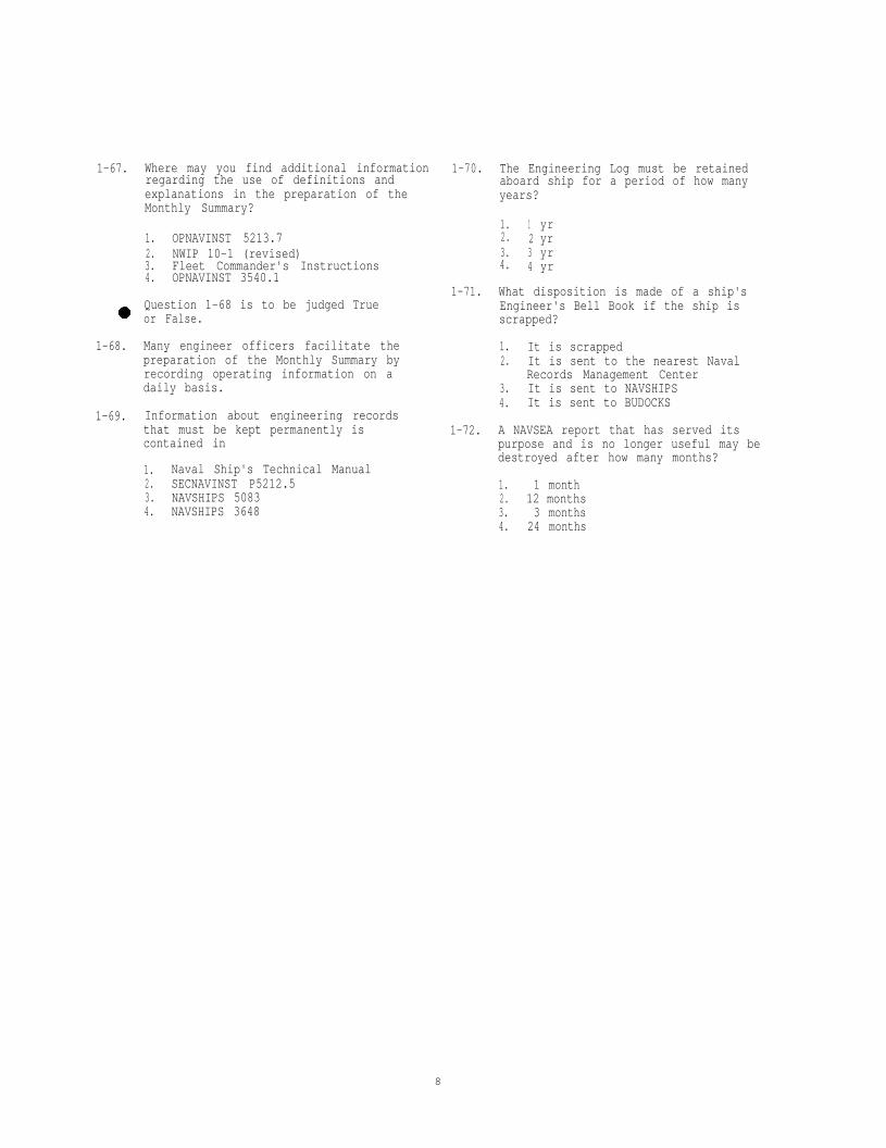
1-67. Where may you find additional information 1-70. The Engineering Log must be retainedregarding the use of definitions and aboard ship for a period of how manyexplanations in the preparation of the years?Monthly Summary?
1. OPNAVINST 5213.72. NWIP 10-1 (revised)3. Fleet Commander's Instructions4. OPNAVINST 3540.1
Question 1-68 is to be judged Trueor False.
1. 1 yr2. 2 yr3. 3 yr4. 4 yr
1-71. What disposition is made of a ship'sEngineer's Bell Book if the ship isscrapped?
1-68. Many engineer officers facilitate thepreparation of the Monthly Summary byrecording operating information on adaily basis.
1-69. Information about engineering recordsthat must be kept permanently iscontained in
1. Naval Ship's Technical Manual2. SECNAVINST P5212.53. NAVSHIPS 50834. NAVSHIPS 3648
1. It is scrapped2. It is sent to the nearest Naval
Records Management Center3. It is sent to NAVSHIPS4. It is sent to BUDOCKS
1-72. A NAVSEA report that has served itspurpose and is no longer useful may bedestroyed after how many months?
1. 1 month2. 12 months3. 3 months4. 24 months
8

Assignment 2
Administration, Supervision, and Training (cont)
Textbook Assignment: Engineman 1&C, NAVEDTRA 10543-E1, Pages 2-12 through 2-39
Learning Objective: Recognize thepurpose and the importance of Trendand Spectrographic Analyses.
Question 2-1 is to be judged True orFalse.
2-1. Trend and spectrographic analyses are usedto spot impending engine malfunctions.
2-2. Which of the following is a means used todetermine if an engine needs to beoverhauled?
1. The current operating data is comparedwith the previous operating data
2. The operating data of the engine iscompared with that of another engineof the same type
3. The temperature of the lube oilentering the oil cooler is compared tothat of the one leaving the cooler
4. The last two operating data sheets arecompared
2-3. How are engine performance data used as atool?
1. They are used to circle the readingsthat are out of limits
2. They are used to make graphs3. They are used to bring the out of
limit readings to the attention of theengineer officer
4. They are used to discuss the operatingdata with all operators
2-4. In order to produce meaningful graphs fora generator, what load percentage shouldthe data indicate?
1. 25%2. 50%3. 80%4. 100%
2-5.
2-6.
2-7.
2-8.
2-9.
2-10.
Questions 2-5 and 2-6 are to be judgedTrue or False.
In most cases, a set of readings shouldbe plotted every 200 hours of engineoperation.
Engine performance data should beobtained within 5 minutes after start up.
When preparing a graph, at what operatinghour do you place your first point forlube oil consumption?
1. 1002. 2003. 3004. 400
Which of the following information can beobtained from the curves on graphs?
1. The condition of the engine2. What needs to be done to the engine3. The life expectancy of vital parts4. All of the above.
What can you determine from aspectrometric analysis of engine oil?
1. The extent of accelerated wear of aninternal combustion engine
2. The amount of oil the engine uses permonth
3. The rate of flow of the cooling waterto the lube oil cooler
4. The amount of oil pressure producedby the lube oil pump
Questions 2-10 and 2-11 are to be judgedTrue or False.
After major overhaul, ships should,maintain accurate records of operatinghours, including oil changes, andsamplings in order to provide the testingfacility with the information indicatedin the sampling kit.
9

2-11. After an oil sample is received at ashipyard or an IMA, a physical test and aspectrometric analysis are performed.
2-16.
Learning Objective: Point out someadministrative and supervisoryresponsibilities in relation tosubordinate personnel, the procure-ment of repair parts and materials,scheduling jobs, and estimating timeand materials for a job.
2-17.
2-12. In addition to the supply officer, who is 1. DD Form 1150responsible for taking the initiative in 2. DD Form 1348maintaining an adequate supply of 3. NAVSUP Form 1250engineering spare parts? 4. NAVSUP Form 4757
1. Engineer officer2. Main propulsion assistant3. Prime users of the parts4. Senior supply petty officer
2-13. Aboard ship, which of the following isNOT one of your responsibilities inconnection with maintenance and repair?
1. To select materials on the basis ofservice conditions they mustwithstand
2. Issue and account for materialrequired for the support of the ship
3. Identify repair parts frommachinery that is familiar to you
4. Know where to look for informationon repair parts and material you willuse
2-14. What should you do when materials andrepair parts are not specified in theinstructions accompanying a job?
1. Always use your own judgment2. Never use your own judgment3. Look for the information4. Refuse the job until you are provided
with the information
2-15. Which of the following sources ofinformation is helpful in identifying orselecting materials and repair parts?
1. Stock cards maintained by the supplyofficer
2. Ship's plans and blueprints3. Coordinated Shipboard Allowance List4. All of the above
2-18.
2-19.
2-20.
2-21.
2-22.
Which of the following sources ofinformation should you consult to obtainthe National Stock Numbers of repairparts for a diesel engine cylinder linerand gaskets?
1. Planned Maintenance System Manual2. Coordinated Shipboard Allowance List3. Nameplate on the equipment4. Each of the above
What document should you use to request arepair item stocked in the supplydepartment aboard ship?
Which of the following sources ofinformation is/are NOT likely to identifythe type of material used inmanufacturing a gear for a fuel oilservice pump?
1. Nameplate on the pump2. Stock cards maintained by the supply
officer3. Ship's plans and blueprints4. Coordinated Shipboard Allowance List
Questions 2-19 and 2-20 are toTrue or False.
be judge
When unable to locate the National StockNumber of an item you are requesting froma shipboard supply department, you shouldfurnish the supply personnel with enoughstandard information to help identify theitem.
SECAS is the designated systemresponsible for maintaining the CASREPstatus of your ship.
Who is responsible for ensuring that theproper documentation is completed andprocessed as described in Volume II ofOPNAVINST 4790.41
1. The commanding officer2. The engineer officer3. The work center supervisor4. The ship's 3-M coordinator
At the individual equipment level, whichof the following forms is used to reporta configuration change?
1. OPNAV Form 12502. OPNAV Form 13483. OPNAV Form 4790/2K4. OPNAV Form 4790/CK
10

2-23. A work request to repair a pump shaft hasbeen designated as a ship-to-ship job.Which of the following actions will theship's force personnel be expected toperform?
1. Disassemble the pump and remove theshaft
2. Deliver the shaft to the repair shop3. Pick up the shaft when the repair
work has been completed4. All of the above
2-24. All tests required to be performed byQuality Assurance must be witnessed bythe
2-25.
1. commanding officer2. ship's force3. type commander4. SIMA repair officer
Under which of the following conditionswould you use the OPNAV Form 4790/2K?
1. To request transferring a piece ofequipment to another work center
2. To request PMS MaintenanceRequirement Cards
3. To request a shipyard's assistance4. To request consumable materials
2-26. What is the purpose of the OPNAV Form4790/2L?
1.2.
To defer a piece of equipmentTo document completion of a joborder
3. To request work from an IMA4. To amplify information described
on a 4790/2K
2-27. Which of the following forms is anautomated work request producedwith computer capabilities?
by an IMA
1. OPNAV Form 4790/2K2. OPNAV Form 4790/2L3. OPNAV Form 4790/2Q4. OPNAV Form 1348
2-28. Checking on the availability of materialsbefore starting work on a maintenance jobis an important part of careful planningbecause failure to do so may result inwhich of the following conditions?
1. Wasted effort2. Unsafe working condition3. Useless equipment4. All of the above
2-29. The amount of information required to begiven to the personnel doing a particularrepair job will depend largely on whichof the following considerations?
1. The safety precautions you expectthem to ignore
2. The manhours estimated to completethe job
3. The experience of the personnelassigned to the job
4. The degree of care with which youexpect to inspect the job uponcompletion
Question 2-30 is to be judged True orFalse.
2-30. A careful inspection should be conductedafter a job has been completed to ensurethat the work was properly performed andthat necessary records or reports havebeen prepared.
2-31. When estimating the amount of timerequired to accomplish a repair, whatfactor(s) should you take intoconsideration?
1. The personnel who can best do the job2. The number of personnel required for
the work3. The availability of the repair
materials4. Each of the above
Questions 2-32 and 2-33 are to be judgedTrue or False.
2-32. The accuracy of job estimates that youmust submit to your division officer isimportant because such estimates mayaffect the operational schedule of theship.
2-33. When more than one shop is required tocomplete an engine repair, each shopshould make a separate time estimate ofthe job.
2-34. Besides the actual time required for thework itself, what other factors must beconsidered in arriving at a finalestimate for a particular job?
1. Drills2. Inspections3. Working parties4. All of the above
11

Question 2-35 is to be judged True orFalse.
2-35. Dividing a total job into sub-jobs andthen determining the time and number ofpersonnel required for each sub-job is awaste of labor and time for the purposeof arriving at accurate estimates.
2-36. Which of the following estimates is oftenthe most difficult for a supervisor tomake in arriving at a job completiontime?
1. Tools required2. Materials required3. Personnel required4. Time and labor required
2-37. You are responsible for submitting anestimate of the materials required tocomplete a job. If the job is one yourshop handles regularly, which factor is abasis for making an accurate estimate?
1. Records of the jobs kept by the shop2. In-service conditions to be fulfilled3. Condition of tools and equipment4. Availability of the materials
Question 2-38 is to be judged True orFalse.
2-38. In estimati ng material needs for a job,you should make allowances for waste.
Learning Objective: Indicatepractices and procedures usedwhen training personnel.
2-39. In addition to the technical competencethat you must possess before you canteach others, which of the followingfunctions should you also be capable toperform?
1. Organize information2. Present information
effectively3. Motivate your students4. All of the above
Question 2-40 is to be judged True orFalse.
2-40. From a training standpoint, each personon watch in the engineroom is required tofunction as part of a team because of theclose relationship between eachwatchstander's duties.
2-41. Which of the following factors helpsdetermine the procedures for training anew person in engineroom operations?
1. Ship's operating schedule2. Number of experienced men available3. Condition of engineroom machinery4. Each of the above
2-42. An Engineman striker who is newlyassigned to the engineroom is not readyfor messenger duty training until hebecomes familiar with the
1. duties of the throttleman2. technique of reading pressure gages3. procedures of starting or securing
the main propulsion plant4. locations of all machinery,
equipment, piping, and valves
2-43. During what part of an engineroomwatchstander's training should a studentlearn how to take gage readings?
1. While learning the duties of thethrottleman
2. While learning the duties of themessenger
3. After becoming proficient in theduties of the throttleman
4. After learning to perform the dutiesof the throttleman
2-44. When should an Engineman striker betrained to perform the duties of athrottleman?
1. After becoming competent inadministrative requirements
2. After becoming proficient in theduties of the messenger
3. While learning the duties of themessenger
4. While learning specific basic safetyprecautions
Questions 2-45 and 2-46 are to be judgedTrue or False.
2-45. A good way to start on-the-job trainingfor the throttleman's job is to assign anexperienced throttleman to supervise thetrainee.
2-46. As the instructor of engineroompersonnel, you should analyze and applyyour own experiences and reactions tohelp trainees learn more effectively.
12

2-47.
2-48.
2-49.
2-50.
2-51.
2-52.
2-53.
2-54.
Which of the following factors should beincluded in the training of engineroompersonnel?
1.
2.
3.
4.
Consideration of the individualdifference in the learning rates ofpersonnelTime to be spent on engine theoryprior to manual operationEncouragement of personnel to noticeand discuss differences in the waysthat engines behave during operationEach of the above
Question 2-48 is to beFalse.
judged True or
An experienced Engineman reporting aboardfor duty from another type of ship willrequire a certain amount of retraining toqualify as a watchstander.
Which of the following factors should beemphasized constantly throughout anengineroom training program?
1. Safety precautions2. Trial-and-error techniques3. Emergency repair procedures4. Machinery characteristics
Questions 2-50 through 2-53 are to bejudged True or False.
The PQS program is a methodensure quality assurance.
designed to
Most PQS standards are divided into foursections.
The watchstation section defines theactual duties, assignments, andresponsibilities needed forqualification.
As a work center supervisor, it is NOTabsolutely necessary for you to be PQSqualified in all the equipment under yourcontrol.
When personnel are assigned to repair V,where should the emphasis be placed?
1. PQS, qualification in damage control2. PQS, qualification in engineroom
takeover3. PQS, qualification in ship's 3-M
system4. PQS, qualification in first aid
2-55. As a repair party leader, you areresponsible for which of the followingfunctions?
1. Knowing how many personnel on theship are fully qualified in damagecontrol
2. Training your repair party personnelon the equipment they will be using
3. Training your repair party personnelin the function of a repair party
4. Both 2 and 3 above
2-56. What two Status Boards is Repair Vrequired to maintain?
1. Stability and liquid load2. Auxiliary and main propulsion
machinery3. Air and surface contacts4. Personnel casualty and radiological
Learning Objective: Recognize thepurpose and the importance of theEngineering Operational SequencingSystem (EOSS).
Question 2-57 is to be judged True orFalse.
2-57. The EOSS was developed to help combat theproblems created by rapid turnover ofpersonnel and the lack of neededinformation.
2-58. When the EOSS is used properly itaccomplishes which of the followingconsiderations?
1. Reduces operational casualties2. Provides better plant control3. Extends the operational life of
machinery4. All of the above
2-59. Under Stage I of the EOP, who has directcontrol of an evolution involving thestarting and securing of a main engine?
1. The engineering officer of the watch2. The engineroom top watch3. The main propulsion asistant4. The engineer officer
13
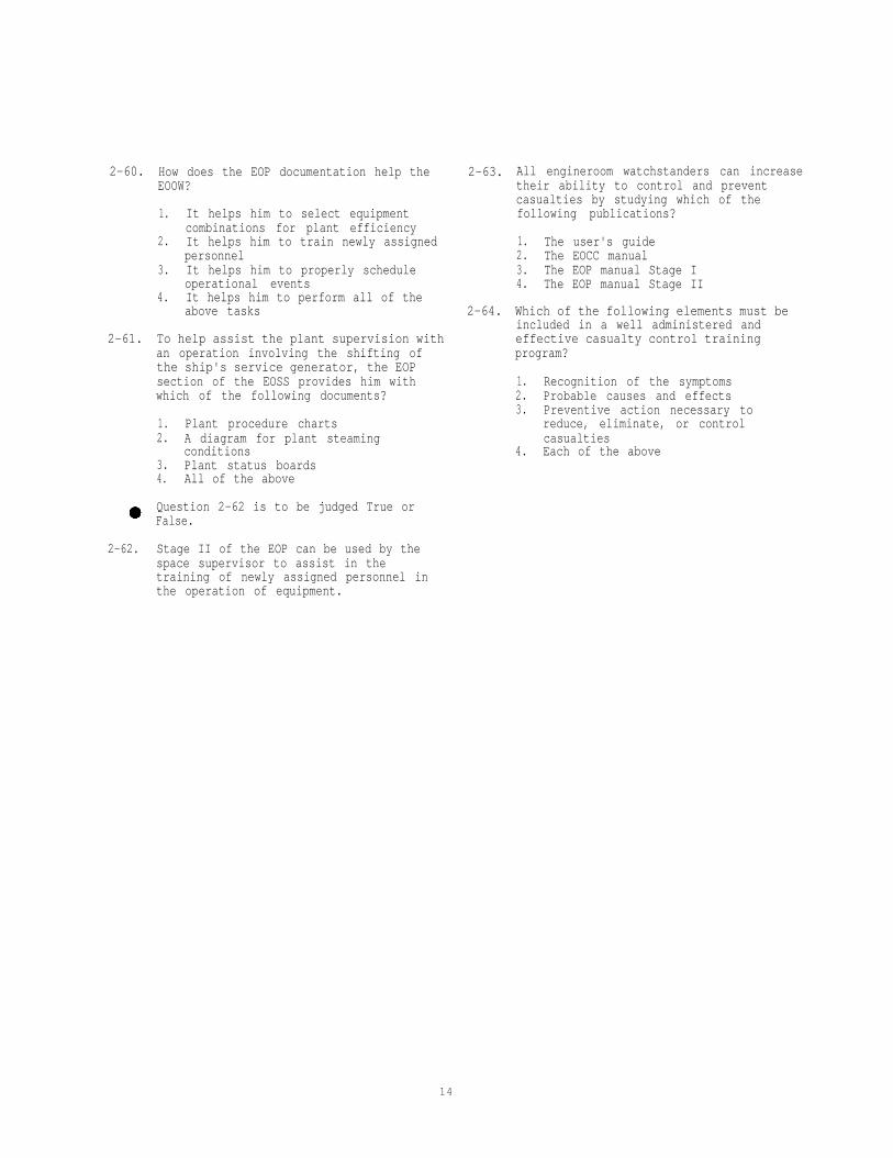
2-60. How does the EOP documentation help theEOOW?
1. It helps him to select equipmentcombinations for plant efficiency
2. It helps him to train newly assignedpersonnel
3. It helps him to properly scheduleoperational events
4. It helps him to perform all of theabove tasks
2-61. To help assist the plant supervision withan operation involving the shifting ofthe ship's service generator, the EOPsection of the EOSS provides him withwhich of the following documents?
1. Plant procedure charts2. A diagram for plant steaming
conditions3. Plant status boards4. All of the above
Question 2-62 is to be judged True orFalse.
2-63. All engineroom watchstanders can increasetheir ability to control and preventcasualties by studying which of thefollowing publications?
1. The user's guide2. The EOCC manual3. The EOP manual Stage I4. The EOP manual Stage II
2-64. Which of the following elements must beincluded in a well administered andeffective casualty control trainingprogram?
1. Recognition of the symptoms2. Probable causes and effects3. Preventive action necessary to
reduce, eliminate, or controlcasualties
4. Each of the above
2-62. Stage II of the EOP can be used by thespace supervisor to assist in thetraining of newly assigned personnel inthe operation of equipment.
14

Assignment 3
Administration, Supervision, and Training (Cont'd)
Textbook Assignment: Engineman 1&C, NAVEDTRA 10543-E1, Pages 2-39 through 2-53
Learning Objective: Recognize the purposeof and the types of inspections held inthe engineering department aboard ship,and describe the methods and proceduresfor conducting each.
Information for questions 3-1 and 3-2.An inspection party from destroyer A
boards destroyer B and proceeds to carry outa competitive material inspection.
3-1.
3-2.
3-3.
3-4.
Which of the following officers most pro-bably determined the type of inspection tobe held aboard destroyer B?
3-6. An administrative inspection of a ship'sengineering department is principallyconcerned with the department's
1. Fleet commander2. Type commander3. Commanding officer of destroyer B only4. Commanding officer of destroyer B and
the commanding officer of destroyer A
1. paper work2. administration of divisional
responsibilities3. assignment of personnel to
administrative duties4. training facilities
The inspection party was most probably 3-7. Who normally provides checkoff lists forselected by the administrative inspections of ships?
1. CNO 1. Type commander2. type commander 2. Division commander3. division commander 3. Captain of the ship that will conduct4. commanding officer of destroyer A the inspection
Questions 3-3 and 3-4 are to be judgedTrue or False.
4. Captain of the ship that will beinspected
The administrative inspection of a ship'sengineering department is concerned withthe ship's readiness to carry out itsbasic mission.
3-8. An administrative inspection is beingconducted in the engineering department.Which of the following bills should beinspected by the assistant inspector foradequacy, completeness, and correctness?
The appearance of the engineering 1. Fueling Billpersonnel is evaluated for grading 2. Engineering Casualty Billpurposes during administrative inspec- 3. Watch, Quarter, and Station Billstions. 4. All of the above
3-5. During the general administration inspec-tion, which of the following has a directbearing on the ship's engineeringdepartment?
1. Acquaintance of engineering personnelwith the ship's administrativeprocedures
2. Proper maintenance of operating logs3. Indoctrination procedures for new
personnel4. All of the above
15

3-9. The best way for an inspector to deter- 3-14. The operational readiness observing partymine whether personnel are familiar with differs from the administrativethe operating instructions of their inspecting party in that it usuallydepartment is to question the contains
3-10.
3-11.
3-12.
3-13.
1. department head concerning themethods of instruction
2. leading petty officers of thedepartment
3. newly assigned or nonrated personnelin the department
4. personnel at random
How does an inspector determine themethods employed in the engineeringdepartment to locate stowed items?
1. By examining the various supplyrecords and forms
2. By inspecting the stowage bins andboxes
3. By asking a senior petty officer howhe would locate an item
4. By questioning a department officeron the methods employed
What type of inspection is mainly con-cerned with a ship's ability to carry outits wartime missions?
1. Administrative inspection of theship as a whole
2. Administrative inspection of theship's departments
3. Operational readiness inspection4. Material inspection
1. fewer warrant officers2. more third class petty officers3. fewer commissioned officers4. more leading petty officers
3-15. What is the primary function of thebattle problem as it is related to theengineering department of a ship?
3-16.
3-17.Which of the following types of inspec-tions include battle problems?
1. Material inspections and operationalreadiness inspections
2. Operational readiness inspectionsonly
3. Material inspections only4. All formal inspections
HOW is a ship's performance during itsoperational readiness inspectionmeasured?
1. By the standard of professional abi-lity attained by the crew
2. By the ship's ability to perform itswartime functions adequately
3. By the completeness, adequacy, andimplementation of its Battle Bill
4. All of the above
3-18.
1. To test the teamwork within thedepartment
2. To evaluate the quality of the ship'sequipage
3. To test the skill of rated personnelin the department
4. To measure the operational efficiencyof the engineering machinery
The value of a battle problem to a ship'scompany is directly proportional to the
1. amount of preparation time allowedthe ship's company before zeroproblem time
2. amount of realism provided in theproblem
3. skill of the observing partyevaluating operational procedures
4. number of trained observersconducting the problem
What specific element increases thevalue of a battle problem to a ship'scompany?
1. Surprise2. Dress rehearsal3. Advance notice4. Suspense
Which of the following types of infor-mation should be supplied to a shipbefore a battle problem begins?
1. The time of "darken ship" inspection2. The time of a simulated casualty to
the power supply3. The end of problem time4. The time of JV telephone circuit
casualty
16

3-19.
3-20.
3-21.
3-22.
Question 3-19 is to be judged True orFalse.
When practicable, during a battleproblem, pertinent information should begiven verbally by observers to the ship'screw.
When may an observer coach ship's person-nel during a battle problem?
1. When questioned by personnelconcerning imposed casualties
2. When imposed casualties areundiscovered by personnel
3. When it is inconvenient to simulatecasualties
4. When the corrective action taken bypersonnel is inappropriate
During a battle problem, a valve must beclosed in order to simulate a casualty toa main engine. Which of the followingpersonnel should actually close thevalve?
1. The assistant inspector2. A member of the observing party3. A member of the ship's engineering
force4. Either a member of the ship's
engineering force or a member ofthe observing party
During a battle problem, an observer hasrequested that the feedwater to theboilers be shut off to simulate a boilercasualty. What should theofficer of the watch do?
engineer
1. Direct the engineroom personnel to dowhatever the observer requests
2. Not permit this to be done3. Make sure the supply of lubricating
oil to the main engines is stoppedat the same time
4. Allow only the observer to handlethe shutoff valve
3-23. Which of the following personnel areresponsible for setting up provisions foremergency action in case of a realcasualty during a battle problem?
3-24.
3-25.
3-26.
3-27.
3-28.
Who uses the engineering telephone cir-cuits during the battle problem?
1. The observing party, to announcestart and end of the problem
2. The observing party, in case ofactual casualty
3. The ship's personnel, in case ofactual casualty
4. The ship's engineering personnel, tocope with the battle problem assignedto the ship
Question 3-25 is toFalse.
be judged True or
In a shipboard battle problem, observersshould use equal effort to noteexcellence as well as weakness.
The analysis of a battledivided into two steps:
problem is
1. critique and observers' reports2. captain's report and observers'
reports3. critique and ship's company report4. observers' and ship's company reports
Which of the following personnel attendthe critique that is held aboard shipafter a battle problem?
1. Commanding officer, department heads,chief observer, and senior observers
2. All ship's officers, chief observer,and senior observers
3. All ship's officers, some chiefs andfirst class petty officers, chiefobserver, and senior observers
4. All ship's officers, some chiefs andfirst class petty officers, and chiefobserver
Who sets down the formatobservers' reports?
of the
1. The senior observer for each depart-ment
2. The chief observer3. The type commander4. The fleet commander
1. Type commander2. Ship's company and the observing
party3. Ship's company only4. Observing party only
17
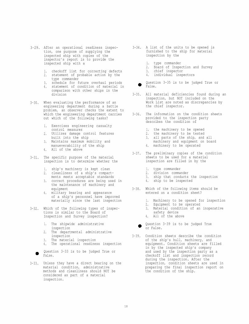
3-29. After an operational readiness inspec-tion, one purpose of supplying theinspected ship with copies of theinspector's report is to provide theinspected ship with a
1. checkoff list for correcting defects2. statement of probable action by the
type commander3. schedule for future overhaul periods4. statement of condition of material in
comparison with other ships in thedivision
3-30. When evaluating the performance of anengineering department during a battleproblem, an observer checks the extent towhich the engineering department carriesout which of the following tasks?
3-31.
1. Exercises engineering casualtycontrol measures
2. Utilizes damage control featuresbuilt into the ship
3. Maintains maximum mobility andmanueverability of the ship
4. All of the above
The specific purpose of the materialinspection is to determine whether the
1. ship's machinery is kept clean2. cleanliness of a ship's compart-
ments meets acceptable standards3. correct procedures are being used in
the maintenance of machinery andequipment
4. military bearing and appearanceof a ship's personnel have improvedmaterially since the last inspection
3-32. Which of the following types of inspec-tions is similar to the Board ofInspection and Survey inspection?
3-34. A list of the units to be opened isfurnished to the ship for materialinspection by the
1. type commander2. Board of Inspection and Survey3. chief inspector4. individual inspectors
Question 3-35 is to be judged True orFalse.
3-35. All material deficiencies found during aninspection, but NOT included on theWork List are noted as discrepancies bythe chief inspector.
3-36. The information on the condition sheetsprovided to the inspection partydescribes the condition of
1. the machinery to be opened2. the machinery to be tested3. all parts of the ship, and all
machinery and equipment on board4. machinery to be operated
3-37. The preliminary copies of the conditionsheets to be used for a materialinspection are filled in by the
3-38.
1. type commander2. division commander3. ship that conducts the inspection4. ship to be inspected
Which of the following items should beentered on a condition sheet?
1. Machinery to be opened for inspection2. Equipment to be operated3. Material condition of an inoperative
safety device4. All of the above
1. The shipwide administrative Question 3-39 is to be judged Trueinspection or False.
2. The departmental administrativeinspection 3-39. Condition sheets describe the condition
3. The material inspection of the ship's hull, machinery, and4. The operational readiness inspection equipment. Condition sheets are filled
in by the inspected ship's companyQuestion 3-33 is to be judged True orFalse.
3-33. Unless they have a direct bearing on thematerial condition, administrativemethods and cleanliness should NOT beconsidered as part of a materialinspection.
and used by the inspection party as acheckoff list and inspection recordduring the inspection. After theinspection, condition sheets are used inpreparing the final inspection report onthe condition of the ship.
18

3-40. Why is chapter 090 of the Naval Ships'Technical Manual important?
1. It is a guide for use when openingparticular machinery units
2. It is a comprehensive materialinspection guide
3. It is a guide for preparing WorkLists
4. It is a guide for preparingCondition Sheets
3-41. Who furnishes the condition Sheets usedin material inspections?
1. Inspecting party2. Inspected ship3. Division commander4. Type commander
3-42. Which of the following statementsdescribes the manner in which a materialinspection should proceed?
1. All equipment of the same type shouldbe inspected simultaneously
2. A predetermined inspection scheduleshould be followed
3. Inspection of each space should becompleted before the next is begun
4. Inspections of all units should bemade with the knowledge and assis-tance of ship's personnel
3-43. Which of the following is a main inspec-tion item for a material inspection ofengineering spaces?
1. Procedures used for the replacementof repair parts
2. Installation and maintenance ofrequired firefighting equipment inthe engineering spaces in accordancewith up-to-date procedures
3. Maintenance of equipment custodycards
4. Knowledge by responsible engineeringpersonnel of current instructionsregarding routine testing andinspections
3-44. After a material inspection, one purposeof supplying the inspected ship withcopies of the inspector's report is toprovide the ship with a
1. checkoff list for correcting defects2. statement of probable action by the
type commander3. schedule for future overhaul periods4. statements of condition of material
in comparison with other ships in thedivision
3-45. Who evaluates the results of a materialinspection on the basis of reportssubmitted to the inspector of eachinspection group?
1. CNO2. Type commander3. Ship's commanding officer4. Chief inspector
3-46. The main difference between a materialinspection group and the Board ofInspection and Survey is that the Board
1. is interested mainly in operationalreadiness
2. is not from Forces Afloat, but isespecially appointed
3. contains at least 10 officers4. is interested mainly in
administrative efficiency
3-47. Following a shipboard materialinspection, which of the following itemswill be included in the report submittedby the Board of Inspection and survey?
1. The general condition of the ship2. The suitability of the ship for
further service3. A list of proposed repairs, altera-
tions, and design changes4. All of the above
3-48. After conducting trials and inspectionsof a new or converted ship prior to finalacceptance for naval service, the Boardof Inspection and Survey will include inits report all of the following informa-tion EXCEPT the
1. recommended changes in design2. existing defects and deficiencies
in material and performance3. explanation of how speed and shaft
horsepower are determined4. opinion as to who is responsible for
correcting reported defects
3-49. To whom does the Board of Inspection andSurvey submit recommendations for theacceptance or rejection of a new ship?
1. Bureau of Ships2. Prospective fleet commander3. Chief of Naval Operations4. Secretary of the Navy
19
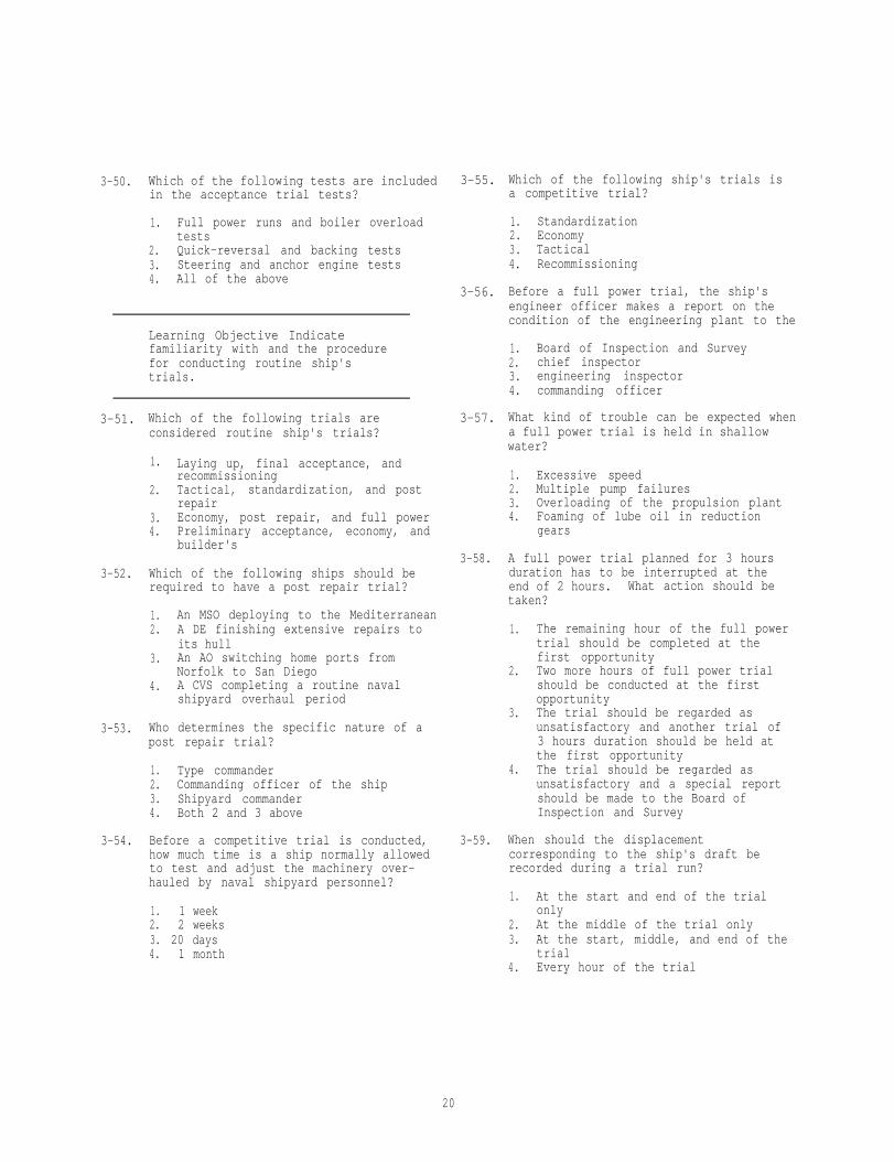
3-50. Which of the following tests are includedin the acceptance trial tests?
1. Full power runs and boiler overloadtests
2. Quick-reversal and backing tests3. Steering and anchor engine tests4. All of the above
Learning Objective Indicatefamiliarity with and the procedurefor conducting routine ship'strials.
3-51. Which of the following trials areconsidered routine ship's trials?
1. Laying up, final acceptance, andrecommissioning
2. Tactical, standardization, and postrepair
3. Economy, post repair, and full power4. Preliminary acceptance, economy, and
builder's
3-52. Which of the following ships should berequired to have a post repair trial?
1. An MSO deploying to the Mediterranean2. A DE finishing extensive repairs to
its hull3. An AO switching home ports from
Norfolk to San Diego4. A CVS completing a routine naval
shipyard overhaul period
3-53. Who determines the specific nature of apost repair trial?
1. Type commander2. Commanding officer of the ship3. Shipyard commander4. Both 2 and 3 above
3-54. Before a competitive trial is conducted,how much time is a ship normally allowedto test and adjust the machinery over-hauled by naval shipyard personnel?
1. 1 week2. 2 weeks3. 20 days4. 1 month
3-55. Which of the following ship's trials isa competitive trial?
1. Standardization2. Economy3. Tactical4. Recommissioning
3-56. Before a full power trial, the ship'sengineer officer makes a report on thecondition of the engineering plant to the
1. Board of Inspection and Survey2. chief inspector3. engineering inspector4. commanding officer
3-57. What kind of trouble can be expected whena full power trial is held in shallowwater?
1. Excessive speed2. Multiple pump failures3. Overloading of the propulsion plant4. Foaming of lube oil in reduction
gears
3-58. A full power trial planned for 3 hoursduration has to be interrupted at theend of 2 hours. What action should betaken?
1. The remaining hour of the full powertrial should be completed at thefirst opportunity
2. Two more hours of full power trialshould be conducted at the firstopportunity
3. The trial should be regarded asunsatisfactory and another trial of3 hours duration should be held atthe first opportunity
4. The trial should be regarded asunsatisfactory and a special reportshould be made to the Board ofInspection and Survey
3-59. When should the displacementcorresponding to the ship's draft berecorded during a trial run?
1. At the start and end of the trialonly
2. At the middle of the trial only3. At the start, middle, and end of the
trial4. Every hour of the trial
20

3-60.
3-61.
3-62.
3-63.
3-64.
3-65.
3-66.
Who determines the full-power rpmrequirements for a ship that is runninga full-power trial?
1. The chief observer2. The type commander3. BUSHIPS4. The Chief of Naval Operations
Question 3-61 is to be judged True orFalse.
Before the official full power trialperiod starts, the ship is normallyoperated at full power long enough topermit all readings to become constant.
An economy trial isover a period of
normally conducted
3-67. When a minimum draft has NOT beenspecified by trial requirements, theliquid loading should NOT be less thanwhat percentage of the full loadcapacity?
3-68.
1. 25%2. 50%3. 75%4. 90%
When should the chief observer determinethe ship's draft and trim for a trial?
1. Before and after the trial2. At the middle of the trial3. At the start, middle, and end of the
trial4. Every hour of the trial
1. 6 hr2. 5 hr3. 3 hr4. 4 hr
Question 3-63 is to be judged True orFalse.
3-69. A competitive trial report normallyincludes data on
1. condenser water injection anddischarge temperatures
2. consumption of fuel oil per hour3. bearing clearances before and after
the trialWhen a ship fails a performance trial, 4. ship's trim under full powerthe type commander may specify a retrialwhich he deems appropriate to, demonstrate 3-70. How often are readings taken and recordedsatisfactory engineering readiness. during an economy trial?
Which of the following actions is NOT aduty of the assistant chief observer?
1. Taking counter readings2. Supervising the engineroom observers3. Checking tank soundings4. Checking fuel oil meter readings 3-71.
Which of the following personnel makesout the economy trial report?
1. Commanding officer2. Chief observer3. Assistant chief observer4. The assistant observers
What information should be furnished inwriting to the chief observer prior tothe start of a full power trial?
3-72.
1. Date of last undocking2. Dates of last testing of all
machinery safety devices3. Authorized and actual settings of
all main machinery safety settings4. All of the above
1. Every half hour2. Every hour3. At the start and end of the trial4. At the start, middle, and end of the
trial
A ship undergoing a 4-hour full powertrail is equipped with a torsionmeterfor measuring shaft horsepower. Todetermine the power being developed,how many observations should be taken?
1. At least one during the trial2. At least two during the trial3. At least one each hour4. At least two each hour
Which of the following is NOT a responsi-bility of engineering departmentpersonnel during an engineering trial?
1. To provide observers with a writtenstatement of the date of the ship'slast undocking
2. To ensure that clocks aresynchronized in all engineeringspaces and on the bridge
3. To provide the usual "housekeeping"and auxiliary loads
4. To check the setting of machinerysafety devices
21

Assignment 4
ENGINE MAINTENANCE
Textbook Assignment: Engineman 1&C, NAVEDTRA 10543-E1, Pages 3-1 through 3-24
Learning Objective: Describe theprocedure and equipments used toinspect and test-run dieselengines.
4-1.
4-2.
4-3.
4-4.
4-5.
Questions 4-1 through 4-4 are to bejudged True or False.
A comparatively minor engine malfunction,if not recognized and remedied in itsearly stages,never develops into amajor casualty.
Work center personnel must learn torecognize symptoms of developingmalfunctions by using the senses of sight,hearing, smell, and touch.
Because of the safety features which arecommonly incorporated in pumps and similarequipment, considerable loss of capacitymay occur before any external evidence ofdamage is apparent.
When a material failure occurs in anyunit, a prompt inspection of all similarunits will NOT prevent a wave of similarcasualties.
A spring-balanced indicator uses which ofthe following types of pistons?
1. Trunk2. Inverted3. Ball4. Check
22
Questions 4-6 and 4-7 are to be judgedTrue or False.
4-6. The Kiene indicator is used only tomeasure the firing pressure of an engine.
4-7. A multivolt meter is used to measure thevoltage produced by the thermocouplesinstalled in an engine's exhaust system.
Learning Objective:Specify whatmaintenance and adjustments are requiredon temperature regulators, and recognizesome of the troubles that may beencountered.
Question 4-8 is to be judged True orFalse.
4-8. For maximum temperature control, the bulbof the temperature regulator should alwaysbe installed in the inlet side of theengine cooling water piping system.
4-9. At which of the following points shouldthe valve stem of a temperature regulatorbe lubricated?
1. Where the valve stem enters thestuffing box
2. Around the threaded sleeve used formanual control
3. Both 1 and 2 above4. At the temperature adjusting
wheel
4-10. What should you do if the temperatureof the freshwater leaving the enginebecomes too high when the regulatoris set on the lowest adjustment setting?
1. Make sure that the manual pointer isset at the THERMOSTATIC position
2. Make sure that the packing gland isnot binding the valve stem and thevalve stem is not stuck in theminimum cooling position
3. Make sure that the temperaturecontrol element is operating properly
4. All of the above

4-11. The temperature at the bulb of thetemperature regulator drops below the settemperature and the valve positionindicator shows COOLER CLOSED. Which ofthe following remedial measures shouldyou take?
1. Secure the packing gland nut wrenchtight
2. Grind the valve seats until a perfectseal is achieved
3. Insert the bulb into the ship'spiping in the horizontal positionwith the arrow on the indicator diskpoint downward
4. Insert the bulb into the ship'spiping in the vertical position withthe nut at the top of the unit
4-12. Why should a liquid filled bulb of atemperature regulator be installedeither in the vertical position with thenut up or in the horizontal position withthe arrow up?
1. To allow the liquid level to be abovethe end of the internal capillarytube
2. To allow the liquid level to be belowthe capillary tube
3. To prevent liquid from effecting thebellows
4. To ensure that the arrow on theindicator disk is always pointingupward
When answering questions 4-13 through4-15, assume you are in the process of
adjusting a temperature regulator to the dieselengine freshwater cooling system.
4-13. The manual crankpin should be rotateduntil the pointer is aligned with whichof the following marked positions on theindicator plate?
1. Cooler closed2. Cooler bypass3. Thermostatic4. Each of the above
4-14. When is the indicator slid up or down foradjustment to the proper position?
1. After the lower end of the seatingsleeve comes in contact with thelower end of the thermostatic stem
2. Before the lower end of the seatingsleeve comes in contact with thelower end of the thermostatic stem
3. After the lower end of the seatingsleeve comes in contact with theupper end of the thermostatic stem
4. Before the upper end of the seatingsleeve comes in contact with thelower end of the valve stem
4-15. The indicator plate is secured and thepointer and thermostatic center marks arealigned. What is the final valve stemadjustment you should make prior totightening the locknut?
1. Two complete turns into thethermostatic stem past the seatingsleeve contact
2. One complete turn into thethermostatic stem past the seatingsleeve contact
3. Two complete turns into thethermostatic stem past the poppetvalve seating position
4. One complete turn into thethermostatic stem past the poppetvalve seating position
4-16. If the desired temperature of the waterin a diesel engine cooling system is160°F, a properly adjusted temperatureregulator will maintain the water at atemperature between
1. 150° and 160°F2. 150° and 170°F3. 160° and 170°F4. 160° and 18O°F
Learning Objective: Recognize thepurpose and types of heat exchangers;indicate what factors affect theiroperation; and point out the methods ofmaintenance and repair.
4-17. In a marine cooling system installation,which of the following engine coolantsmay be circulated through a heatexchanger?
1. Oil2. Freshwater3. Saltwater4. Both 2 and 3 above
23

Question 4-18 is to be judged True orFalse.
4-18. The two basic types of heat exchangersused on engines are radiator and tubular.
4-19. In the Harrison-type heat exchanger, howdo the liquid coolants pass through theunit?
4-20.
1. Freshwater passes through the tubes,and seawater passes around the tubes
2. Freshwater passes through the tubes,and freshwater passes through thetubes
3. Seawater passes through the tubes,and freshwater passes around thetubes
4. Seawater passes through the tubes,and the seawater passes around tubes
How is excessive scale on the cooler of aheat exchanger usually indicated?
1. By a slow increase in freshwatertemperature
2. By a similiarity between inlet andoutlet pressures
3. By the decrease in freshwatertemperature
4. By a rise in the freshwater tanklevel
4-21. The temperature in the saltwater coolingsystem of an engine should never beallowed to exceed what maximumtemperature?
1. 130°F2. 140°F3. 170°F4. 180°F
4-22. Which of the following conditions cancause a cooler element to become cloggedwith foreign matter?
1. Leak in oil cooler2. Dirty freshwater3. Faulty seawater strainers4. All of the above
Questions 4-23 is to be judged True orFalse.
4-24. Erosion holes in the cooler element of aheat exchanger are usually caused bywhich of the following conditions?
1. A clogged cooler element2. A low-pressure water flow3. Air entrapped in the cooler casing4. Fast movement of grit particles
4-25. By which of the following actions willyou cause internal leaks of a heatexchanger element installed in theengine cooling system?
1. By increasing the oil temperature ofthe cooler
2. By reducing the water pressure to thecooler
3. By allowing continued cooleroperation at excessive pressure
4. By allowing continued cooleroperation at reduced pressure
4-26. The heat exchanger outlet side is used toadmit the proper amount of steam requiredto blow through a clogged cooler elementcontaining which of the followingdeposits?
1. Oil2. Sand3. Grease4. Roth 2 and 3 above
4-27. YOU are performing an air test on a heatexchanger to check for leaks. Whatshould you do after attaching a pressuregage to the inlet line of the element?
1. Immerse the element in a tank ofwater
2. Block off the discharge side of theelement
3. Admit low-pressure air to the inletside of the element
4. Remove the element from the casing
4-28. Which of the following methods should youuse to make an emergency repair to astrut-type heat exchanger?
1. Plug the tube2. Replace the element3. Soft solder the element4. Silver solder the element
4-23. Overlubrication of the circulating waterpump bearings will NOT affect the coolingcapacity to the heat exchanger element.
24

4-29. How should you make emergency repairs to 4-35.a leaky tube of a shell in a tube-type oilcooler?
1. Plug the tube at both ends with aspecial plug
2. Plug the tube at both ends with astrip of neoprene
3. Seal the tube with soft solder4. Seal the tube with solder at the
inlet end only
4-30. Shell-and-tube-type heat exchangers arecleaned by which of the followingmethods?
1. Air lances, steam sprays, or chemicalsolutions
2. Steam sprays or chemical solutionsonly
3. Air or water lances only4. Chemical solutions, air lances, or
water lances
Learning Objective: Recognize casualtiespertaining to lubricating systems andpoint out how they may be avoided.
Question 4-31 is to be judged True orFalse.
4-31. If you will use the proper type of lubeoil in an engine lubricating oil systemyou will ensure that all engine partsreceive sufficient lubrication.
4-32. Pressure in the lubricating system ismaintained by which of the followingdevices?
1. Relief valves2. External relief valves3. Internal pressure regulating valves4. All of the above
4-33. Which of the following conditionsindicate a broken lube oil pump?
1. Smoke rising from the shaft2. Abnormal noise in the pump3. Sudden increase of lube oil
pressure4. Fluctuation of lube oil pressure
4-34. When is the low-pressure warning deviceof a lube oi 1 system usually tested?
1. Every day2. When the system is started and
secured3. Only when the system is started4. Only when the system is secured
4-36.
4-37.
In addition to temperature and pressurereadings, which of the following methodsshould you use to determine if a bearingis receiving oil?
1. After shutdown, inspect bearings todetermine the pressure of the oil
2. After shutdown, place you hand on abearing to note the temperature
3. Both 1 and 2 above4. Blow air through lube oil passages
Which of the following materials shouldyou use when cleaning an engine lube oilsump?
1. Cotton waste2. Paper towels3. Lintfree cloths4. All of the above
You have removed an oil filter line froman engine. Before reinstalling, the lineshould be cleared of any obstructionswith
1. diesel oil2. compressed air3. low-pressure steam4. freshwater lances
Learning Objective: Explain theoperational characteristics of fuelinjection equipment and enginecontrols. Recognize symptoms offuel injection trouble and theircauses, and indicate what correctivemeasures may be required.
4-38. Regardless of design, under which of thefollowing conditions should solid fuelinjection systems deliver the fuel oil toeach engine cylinder?
1. At a high pressure2. In the correct amounts3. At the proper time4. All of the above
4-39. What are the two general types of solidfuel injection systems?
1. Unit injection and common rail2. Jerk pump and common rail3. Individual pump and jerk pump4. Unit injection and individual pump
25

4-40.
4-41.
4-42.
4-43.
4-44.
Question 4-40 is to be judged True orFalse.
The pump-injection system that combines ahigh-pressure pump and fuel injectionnozzle into one unit is called a unitinjector.
Which of the following injection systemsuses a metering device that delivers theappropriate amount of fuel to eachinjector?
1. Atlas2. Cooper-Bessemer3. Bosch4. Cummins
Which of the following factor(s)control(s) the amount of fuel that isinjected by the cam-operated injectorvalves of the basic common-rail injectionsystem?
1. The length of time the nozzle staysopen
2. The pressure held by thehigh-pressure pump in the commonrail
3. The action of the individual valvesmounted on the side of the engine
4. The length of time the nozzle remainsopen and by the pressure held by thehigh-pressure pump in the commonrail
Question 4-43 is to be judged True orFalse.
Most diesel injection equipment operatingproblems are resolved when clean fuel isused.
Which of the following is the best methodto determine whether the bushing assemblyof a unit injector has been damaged?
1. Place the injector in a test standand test the bushing assembly
2. Install the injector in a testengine, operate the engine, andcheck for low firing pressure
3. Disassemble the injector, clean it,and inspect each part of the bushingassembly
4. Install the injector in a testengine, operate the engine, andcheck for low exhaust temperature
4-45. Which of the following operations isaffected by irregularities in the surfaceand helix edge of a plunger?
1. Pumping2. Metering3. Combustion4. Firing
4-46. If the lapped surfaces of a plunger andbarrel assembly are exposed toatmospheric dust, the surfaces will
1. erode2. rust3. score4. bind
Questions 4-47 and 4-48 are to be judgedTrue or False.
4-47. Some fuel oil systems have additionalsafety filters or screens located betweenthe fuel transfer pump and the fueldistributor.
4-48. The absorbent qualities of cotton wastemake it an excellent drying agent forfuel injector parts.
4-49. Lapped surfaces should be handled onlyafter they have been
1. allowed to dry at room temperature2. immersed in clean diesel oil3. washed in distilled water4. dried by heat for several minutes
4-50. External leakage of diesel fuel frompumps and injectors is probably caused bywhich of the following conditions?
1. Loose connections, scored plungers,or cracked housings
2. Scored plungers, improper assembly,or broken springs
3. Eroded bushing ports, looseconnections, or broken springs
4. Improper assembly, loose connections,or cracked housings
4-51. On some fuel injection equipment, mildroughness and discoloration of thesealing surfaces may be removed bywhich of the following methods?
1. Lapping2. Scrapping3. Grinding4. Honing
26
4-52. When the plunger of the injection pump ofa diesel engine is stuck, it usuallycauses which of the following conditions?
1. Engine failure2. Excessive fuel consumption3. Increase in engine temperature4. Failure of a cylinder to fire
4-53. A binding plunger test is being performed.What kind of trouble is indicated by asluggish return of the plunger?
1. A broken plunger spring2. A sticky plunger3. A nicked plunger4. A scored plunger
4-54. In trying to loosen a stuck fuel oilinjector plunger, you should soak theplunger and barrel in which of thefollowing fluids?
1. Clean diesel fuel2. Lubricating oil3. Cleaning solvent4. Unleaded gasoline
4-55. You are cleaning a Bosch fuel injectionpump plunger. What should you do afterrinsing it in fuel oil and blowing itdry?
1. Examine the plunger for defects2. Reassemble the pump assembly3. Place mutton tallow on the plunger4. Wipe the plunger with a mild abrasive
4-56. Which of the following materials shouldNOT be used to free up the plunger andbushing to a G.M. unit injector?
1. Jewelers' rouge2. Mutton tallow3. Clean fuel oil4. Compressed air
4-57. In a diesel engine fuel system, what isthe function of the fuel control rack?
1. To control vaporization of fuel2. To remove impurities from the fuel3. To meter the fuel injected at each
stroke4. To prevent jamming of the fuel
injector plunger
4-58. Which of the following conditions causesan engine fuel oil control rack to stick?
1. End play2. Normal wear3. Gear backlash4. Dirt in the mechanism
4-59. What effect, if any, may backlash in thecontrol rack have on engine performance?
1. High exhaust temperature2. Low firing pressures3. Variations in speed4. None
4-60. Backlash in the fuel control system isoften caused by which of the followingparts?
1. Jammed control rack2. Scored pump plunger3. Distorted pump bushing4. Worn control sleeve
Learning Objective: Discuss the opera-tional characteristics of fuel injectionequipment and engine controls. Recognizesymptoms of fuel injection troubles, aswell as their causes, and indicatecorrective measures that may be required.
Question 4-61 is to be judged True orFalse.
4-61. Improper seating of the exhaust valvesmay cause symptoms similiar to impropertiming of the engine fuel injectionsystem.
4-62. Late timing of fuel being injected into acylinder may be indicated by which of thefollowing conditions?
1. Engine detonation2. Injection pump, leakage3. High exhaust temperature4. Low exhaust temperature
4-63. Which of the following factors may be thecause for a Bosch fuel injector pump togo out of timing?
1. A broken spring2. A stuck plunger3. A worn pump camshaft4. An eroded spill port
4-64. Which of the following correctivemeasures could you use to reduce thenumber of engine governor difficulties?
1. Reduce the engine speed2. Increase the engine load3. Use clean oil4. Adjust the fuel linkage
27

Questions 4-65 and 4-66 are to be judgedTrue or False.
4-65. To maintain the proper oil level in theengine governor, you may use lubricatingoil from the main diesel enginecrankcase.
4-66. Foaming of the oil indicates presence ofwater in an engine governor.
4-67. When the governor compensating needlevalve is correctly adjusted, how shouldthe engine behave during load changes?
1. Maintain low underspeeds2. Maintain high overspeeds3. Return slowly to normal speeds4. Return quickly to normal speeds
4-68. An increase in load for any constantthrottle setting of a mechanical governorwill be accompanied by a decrease in
1. engine speed2. spring length3. fuel pressure4. oil temperature
Question 4-69 is to be judged True orFalse.
4-69. Hydraulic rather than mechanical gover-nors are used where extremely accurateengine speed regulations are required.
4-70. What type of governor is designed to holdthe predetermined operating speed of adiesel engine generator set?
1. Load-limiting2. Variable-speed3. Speed-limiting4. Constant-speed
4-71. The mechanical governor controls engineidling speed when the centrifugal forceof both sets of flyweights act againstwhich of the following parts?
1. The buffer spring2. The light spring3. The heavy spring4. All of the above
4-72.
4-73.
4-74.
4-75.
Which of the following conditions maycause an improper speed fluctuation of anengine equipped with a mechanicalgovernor?
1. Constantly changing loads2. Misfiring engine cylinders3. A binding governor linkage4. Each of the above
An overspeed trip will stop a dieselengine that is equipped with a speedgovernor when the regular speed governorfails to
1. limit the load on the engine2. keep the engine within its maximum
designed limit3. operate4. reduce engine hunt
Question 4-74 is to be judged True orFalse.
Prior to testing the engine overspeedtrip, the accuracy of the engine tacho-meter should be checked for proper opera-tion as required by the manufacturer'sinstructions.
A broken drive shaft of a hydraulicoverspeed trip will cause uncontrolledengine speed because the flyweights
1. disconnect from the shaft2. remain in a distended position3. cease to exert centrifugal force4. increase in rotative speed
28

Assignment 5
Engine Maintenance (cont'd)
Textbook Assignment: Engineman 1&C, NAVEDTRA 10543-E1, Pages 3-25 through 3-41
Learning Objective: Describe thetypes of piston and rod assembliesused in internal combustion engines,recognize symptoms of malfunctionsand their causes, and indicate thetype of actions that may prevent therecurrence of such troubles.
5-1.
5-2.
5-3.
5-4.
Question 5-1 is to be judged eitherTrue or False.
Before attempting to jack an internalcombustion engine over by hand, youshould first disable the startercircuit.
Which of the following symptomsindicate(s) that the clearance betweenthe piston and cylinder is abovetolerance?
1. Excessive oil consumption2. Piston slap after top dead center3. Piston slap after bottom dead center4. All of the above
On Navy engines, piston defects are NOTlikely to be caused by which of thefollowing conditions?
1. Unbalanced load2. Insufficient lubrication3. Crown and land dragging4. Excessive piston liner clearance
Operation of an internal combustion engineabove the specified temperature limits mayresult in which of the following problems?
1. No lubrication of the cylinder walls2. Low cylinder temperatures3. Increased oil viscosity4. High oil temperatures
5-5. If the oil flow to a piston is restricted,where will the oxidation of the oil causedeposits to form?
1. On the underside of the piston crown2. Behind the compression rings3. On the piston walls4. On the piston crown
5-6. When the clearance between the piston andthe cylinder liner is too small, thepiston will NOT likely
1. seize2. bind3. break4. wear in
5-7. The wiping of metal causes the rings tostick in the piston grooves. What is thisaction called?
1. Scoring2. Scuffing3. Calling4. Wiping
5-8. Which of the following actions is/arerequired to balance the load on eachpiston of an auxiliary generator dieselengine?
1. Setting the fuel rack2. Checking the compression pressures3. Checking the firing pressures4. All of the above
5-9. Cracking of the ring groove lands on apiston can be attributed to which of thefollowing conditions?
1. Excessive piston-to-cylinder clearance2. Insufficient clearance between the
ends of the rings3. Insufficient ring-to-land clearance4. Each of the above
29

5-10. Which of the following corrective actionsis recommended for pistons that areexcessively worn?
1. Plating the piston2. Replacing the piston 1.3. Resizing the piston4. Metal spraying the piston
5-11. Which of the following conditions maycause low compression pressures thatmight affect several or all cylinders ofan auxiliary diesel engine?
1. A leaking cylinder valve2. A clogged air filter3. A clogged intake port4. A leaking after-chamber
5-12. Which of the following factors may causeexcessive oil consumption during engineoperation?
1. Worn oil rings2. Use of improper oil3. High lube oil temperatures4. Each of the above
5-13. Which of the following symptoms may beindicative of excessively worn pistonrings?
1. High compression2. Hard starting3. Clear exhaust4. All of the above
5-14. Carbon deposits that limit the flexingmovements of piston rings are usuallyformed when an engine is operated underwhich of the following conditions?
1. Excessive operating temperatures2. High cooling temperatures3. Improper balance4. Improper load
5-15. Which of the following factors may causea piston ring to extend into a port of aported cylinder?
1. Excessive engine speeds2. Insufficient gap clearance 5-22.3. Insufficient ring pressure4. Excessive operating temperatures
5-16. When a piston ring breaks because ofinsufficient end gap, it will have (a)bright spot(s) on what part(s) of thering?
1. Upper side2. Lower side3. Ends4. Face
5-17. When fitted to a liner, if a piston ringlacks sufficient pressure to return toits original shape, what is the ringlikely to do?
2.3.4.
Wear in placeSeize and buckleBind in the grooveBreak under pressure
5-18. Which of the following conditionsprobably causes the greatest amount ofwear on piston rings?
1.2.3.4.
Worn cylinder linersAbnormal carbon depositsInsufficient gap clearanceExcessive operating temperatures
5-19. Which of the following positions isrecommended for piston ring gaps in orderto allow for cylinder wear?
1. All gaps in line with the pistonbosses only
2. All gaps 90° out of line with thepiston bosses
3. All gaps staggered alternately 90°with the piston bosses
4. All gaps in line with the pistonbosses and alternate rings staggered180°
5-20. A ridge in a cylinder liner must beremoved when piston rings are replaced inorder to prevent the
1.2.
bottom ring from crackingtop ring from slipping down
3. top ring and the land from breaking4. rings from slipping too close
together
5-21. If you want to determine the amount ofwear on a piston assembly, you shouldmeasure only those areas that
1. make contact2. are scored3. appear to be worn4. are pitted
Which of the following means are usedto lubricate piston pin bushings?
1. Splash oil2. Pressure oil3. Mechanical oilers4. Oil rings
30

5-23. The interchangeability of piston-pinbushing inserts is dependent on thelocation of the
1. oil holes2. piston pin3. needle bearing4. pin bushing
5-24. Primarily, why are piston pin bushingsreamed?
1. To obtain larger oil holes2. To obtain correct lubricating flukes3. To obtain proper bore clearance4. To correct oil hole positioning
5-25. Which of the following troubles can becaused by misalignment of the connectingrod?
1. Binding of the piston2. Binding of the piston pin3. Binding of the connecting rod journal
4.bearingAll of the above
5-26. Which of the following tools should youuse to prevent overtightening ofconnecting rod bolts?
1. Socket wrench2. Torque wrench3. Strain gauge4. Thickness gauge
5-27. Which of the following connecting rodtroubles is likely to occur because ofoverstress?
1. Cracked rods2. Misaligned rods3. Out-of-round bearing bores4. Plugged oil passages in the rods
Question 5-28 is to be judged Trueor False.
5-28. You should repair by welding or brazingany cracked connecting rods discoveredduring engine overhaul.
Learning Objective: Point out someof the causes of engine shaft andbearing failure and indicate methodsof reducing the most commonlyencountered troubles
5-29.
5-30.
5-31.
5-32.
5-33.
5-34.
5-35.
What is the usual cause of fatiguefailure of the crankshaft journalbearings?
1. Loose bearing shells2. Improper lubrication3. Cyclic peak loads4. Each of the above
What effect will extreme overspeeding ofan internal combustion engine have on themain journal bearings?
1. Failure of the upper halves only2. Failure of the lower halves only3. Either 1 or 2 above4. Failure of both the lower and the
upper halves
Which of the following factors could bethe cause of crankshaft fatigue failure?
1.
2.
3.4.
Improper functioning of the vibrationdamperImproper quenching or balancing bythe manufacturer of the crankshaftFlexing of the crankshaft under loadAll of the above
The crankshaft of a reciprocating enginemay be responsible for which of thefollowing conditions?
1. Lineal impulses2. Natural vibrations3. Torsional impulses4. Natural frequencies
Questions 5-33 and 5-34 are to be judgedTrue or False.
The term "critical speeds" applies to allmoving members of machinery with theexception of reciprocating-type engines.
Continuous engine operation within thecritical speed range may result inbreakage of the crankshaft and connectingrod bearing difficulties.
Assume a propulsion diesel engine has atachometer with the area between 700 rpmand 750 rpm conspicuously marked in red.The speeds within this range are the
1. maneuvering engine speeds2. critical engine speeds3. most efficient operating speeds4. smoothest operating speeds
31

5-36. To reduce torsional fluctuations and 5-43.ensure smoother operation, some dieselengine crankshafts are equipped withwhich of the following devices?
1. Vibration dampers2. Flexible couplings3. Shock absorbers4. Flywheels
5-37. Which of the following lubricants is/areharmful to the rubber of elastic-typevibration dampers?
5-44.1. Lube oil2. Diesel oil3. Light grease4. All of the above
5-38. Which of the following engine noisesindicates an improperly functioningvibration damper?
1. Grinding noises at low speeds2. Clinking noises during starting3. Rumbling noises at normal speeds4. Humming noises at high speeds
Question 5-39 is to be judged Trueor False.
5-39. Crankshaft failure may result fromexcessive main bearing clearances thatallow an uneven distribution of theengine load during operation.
5-40. You can help keep engine journal bearingsfrom wearing out-of-round by preventingwhich of the following conditions?
1. Inadequate lubrication and journalbearing failure
2. Overloading or overspeeding of theengine
3. Excessive crankshaft deflection andmisalignment of parts
4. All of the above
5-41.
5-42.
Which of the following actions is likelyto cause excessive crankshaft deflection?
1. Overloading2. Overspeeding3. Insufficient lubrication4. Excessive operating temperatures
What valve assembly trouble is likely toscore the camshaft cams of an engine?
1. A worn rocker arm bushing2. A broken tapped screw3. A chipped valve spring4. An improperly seated push rod spring
Which of the following inspections to thevalve actuating linkage should be made atfrequent intervals during engineoperation?
1. Inspections for improperly seatedvalve springs
2. Inspections for grooved or scoredcam follower surfaces
3. Inspections for improperly seatedpush rod end fittings
4. All of the above
What is the danger in using an enginelubricating oil that has a viscosityhigher than recommended?
1. Rapid absorption of acids2. Rapid absorption of carbon particles3. Surface pitting of bearings4. Overlubrication
Question 5-45 is to be judged True orFalse.
5-45. When a bearing fails because of aninadequate bond between the bearing metaland the bearing shell, the bearing shellshows through the bearing surface.
5-46. Crankshaft journals that exceed thespecified tolerances for out-of -roundnessshould be refinished by which of thefollowing means?
1. Stoning2. Grinding3. Filing4. Scraping
5-47. A rough spot or ridge located on a crankpin journal should be removed by dressingwith which of the following materials?
1. 4 fine sandpaper2. A crocus cloth3. A fine oil stone4. Both 2 and 3 above
5-48. What damage may result to a crank pinbearing when the piston bushing bore andconnecting rod bore are not in alignment?
1. Cracking at the opposite ends of thelower and upper halves
2. Cracking at the same ends of thelower and upper halves
3. Wiping at the opposite ends of thelower and upper halves
4. Wiping at the same ends of thelower and upper halves
32

5-49. What is indicated when the back of abearing shell contains a gumlike varnishdeposit?
1. Excessive bearing clearance2. Normal bearing wear3. Low operating temperatures4. Lack of lubrication
5-50. If the lower shell of a journal bearingis interchanged during installation witha plain upper shell, what, if anything,happens to the oil flow in the bearing?
1. It decreases2. It increases3. It stops4. Nothing, it remains the same
5-51. Bearing lubrication is poorest when theengine is being
1. overloaded2. idled3. started4. stopped
5-52. What is the purpose of motor-driven lubeoil pumps used on diesel engines?
1. To increase the pressures obtainablefrom the engine-driven pumps
2. To service the engine gear trainingand bearings during normal operation
3. To lubricate the bearings beforeengine operation
4. To increase the flow during engineoperation
5-53. In order to check for abrasive elementsin the lubricating oil of an engine, theoil samples should be obtained regularlyfrom which of the following sources?
1. The most accessible point in the lubeoil system
2. The lowest point in the sump3. The oil filter element4. The lube oil pump
5-54. What part of a frictionless bearingshould you inspect for signs of pittingand surface cracks?
1. Inner surface of the inner race2. Outer surface of the inner race3. Inner surface of the outer race
5-55. Which of the following actions may causedented races in the antifriction bearingsthat support heavy shafts?
1. The application of too much pressurewhen the bearings are installed
2. The application of too much pressurewhen the bearings are removed
3. The application of vibration to thebearings when the shafts are idlefor a long time
4. Each of the above
5-56. A frictionless bearing is always replacedwhen an inspection reveals which of thefollowing problems?
1. It is difficult to operate by hand2. It has brinelled races3. It operates noisily4. It is dirty
5-57. Only one race of an antifriction bearingis made a press fit because it is highlydesirable to have the other race
1. abrade2. creep3. removable4. unloaded
Questions 5-58 and 5-59 are to be judgedTrue or False.
5-58. The only way to tell if a bearing hasa cracked race is by a visual inspection.
5-59. The best way to determine if excessivelooseness exists in a frictionlessbearing is to compare the bearingsuspected of being loose with d newbearing.
5-60. What is the probable cause of loosenessin an oiled roller bearing?
1. Improper adjustment2. Improper installation3. Abrasives in the oil4. Faulty oil seal
4. Outer surface of the outer race
33

Learning Objective: Recognize thepurpose and types of auxiliarydrive mechanisms; and specify thegeneral inspection and maintenancerequirements.
5-61.
5-62.
5-63.
5-64.
5-65.
What is the purpose of the chaindrive mechanism that drives theblower on a diesel engine?
2. To increase the speed of rotation
1. To reduce the speed of rotation of
of the blower
the blower
3. To time the operation of the blowerin the correct sequence of eventswith the operation of the engine
4. To prevent overspeeding of the blower
What gears are used in the gear train forthe auxiliary mechanisms of most internalcombustion engines?
1. Bevel gears2. Single helical spur gears3. Double helical spur gears4. Worm gears
Most internal combustion engine drivegears are constructed of which of thefollowing materials?
1. Steel2. Cast iron3. Bronze4. Fiber
What is the function of idler gears in atiming train?
1. To reduce the speed of the camshaft2. To increase the speed of the camshaft3. To reduce vibrations in the gear
train4. To transfer the rotation of the
crankshaft over a considerabledistance
What is the speed of the camshaft in afour-stroke cycle engine when thecrankshaft is turning 920 rpm?
1. 230 rpm2. 460 rpm3. 690 rpm4. 920 rpm
5-66.
5-67.
5-68.
5-69.
5-70.
5-71.
Question 5-66 is to be judged Trueor False.
A longitudinal movement may be producedby an operating gear in a train that issecured with a loosely fitted woodruffkey.
What is the purpose for marking theteeth in an engine gear train as shownin figure 3-24 of your textbook?
1. To indicate the gear diameters2. To provide a means for mating the
gears3. To identify the size of the gear
teeth4. To indicate the number of gear
teeth
If the bushing clearances on the timinggear train exceed the allowable limit,the bushings should be
1. aligned2. adjusted3. reshimmed4. renewed
If the only defect found in the auxiliarydrive gears is a chipped gear tooth,which of the following actions should youtake?
1. Rebuild the tooth by welding2. Smooth the chipped area by filing3. Replace the gear4. Realign the gear
When the backlash of a blower rotor gearset exceeds the manufacturer's specifiedlimit, what must you do?
1. Replace the gears2. Replace the rotors3. Retime the gears4. Reshim the rotors
Excessive backlash of the blower rotordrive gears may cause scoring of which ofthe following parts?
1. Blower casing2. Shim plates3. Shaft seals4. Blower lobes
34

5-72. An estimate of the life of a Roots blowerrotor gear can be determined by which ofthe following methods?
1. A comparison of charts showing theaverage use and wear with records ofthe use of the particular machine
2. 4 careful study of records of theamount of wear as recorded periodi-cally
3. A study of the manufacturer's esti-mates of lifetime of the gear forthe engine
4. A computation of the amount of usethe machine will receive and thetype of gear used
5-73. When one of the blower rotor drive gearsindicates a slight tooth fracture, whatshould you do?
5-74. Failure of a properly aligned andadequately lubricated chain drive mecha-nism may be caused by which of thefollowing parts?
1. Sheared cotter pins2. Binding joint pins3. Both 1 and 2 above4. Worn chain links
5-75. After a long period of operation, howis a chain drive usually adjusted?
1. By peening the connecting link pins2. By tightening the chain tension3. By replacing the connecting pin4. By realigning the idler gears
1. Replace the gear with one fromanother set
2. Replace the gears with a matchedset
3. Align the gears to prevent furtherdamage
4. Install additional shims to relievetooth contact
35

Assignment 6
Engine Maintenance (cont'd); Reduction Gears and Related Equipment
Textbook Assignment: Engineman 1&C, NAVEDTRA 10543-E1, Pages 4-1 through 4-11
Learning Objective: Recognizeconditions which may affectreduction gear operations and thenecessary corrective actions tobe taken.
6-1. Under normal conditions, which of thefollowing activities effects repairs tothe main reduction gears?
1. Ship's force2. Repair ships3. Manufacturer4. Naval shipyards
6-2. To ensure that gears are properlylubricated, an engineman must ensure thatwhich of the following conditions are met?
1. The oil is clean2. The oil is kept at the correct
temperature3. The proper amount of oil is supplied
to the gears and bearings4. All of the above
Question 6-3 is to be judged True orFalse.
6-3. The reduction gear manufacturer designatesthe exact relief valve settings andpressure to be maintained in thelubrication system to ensure an adequatesupply of oil to the gears and bearings.
6-4. What is the likely result of deliveringtoo little or too much oil to a bearing?
1. An overheated bearing2. An underheated bearing3. A drop in oil pressure4. A drop in oil temperature followed by
a sharp rise in pressure
6-5. Under any operating condition, what is themaximum permissible temperature rise foroil passing through engine bearings.
1. 50°F2. 60°F3. 65°F4. 70°F
6-6. What is the maximum allowed temperature ofthe oil leaving any reduction gear orbearing?
1. 165°F2. 175°F3. 180°F4. 195°F
6-7. Fine metal flakes are usually producedduring run-in of new gears. These finemetal particles, if not removed from thereduction gear lube oil system, may causewhich of the following troubles?
1. Wiped bearings and scored journals2. Clogged spray nozzles3. Deteriorated gear teeth4. All of the above
6-8. Which of the following types of damage togear teeth surfaces are most likely toresult if lubricating oil is contaminatedby water?
1. Erosion and corrosion2. Corrosion and pitting3. Corrosion and scoring4. Erosion and scoring
6-9. The journals of the main gear are severelycorroded because of lube oilcontamination. What repair work should bedone as soon as possible?
1. Overhaul of the gears at a navalshipyard
2. Removal of metal flakes from the oilsystem
3. Realignment of the reduction gears4. Replacement of the pinion bearings
36

6-10. How long, after securing the mainreduction gear, should you circulate thelubricating oil through the system?
1. 15 minutes2. Until the temperature of the oil is
the same as the reduction gear casing3. Until the temperatures of the oil and
reduction gear casing areapproximately the same as theengineroom temperature
4. 30 minutes
6-11. How can you eliminate the condensation ofwater from the inside of a reduction gearcasing?
1. Keep the gear oil heated untilcondensation evaporates
2. Ensure the gear oil circulates at alltimes so that the water may becentrifuged out
3. Renovate the gear oil in a purifierwhile a cooler is operated and thegear is jacked
4. Allow the gear oil to remain 6-17.unstirred so that water may settleto the bottom of the casing
6-12. Satisfactory operation of which of thefollowing components should keep the lubeoil in good condition?
1. Centrifuge and blower2. Strainer and filter3. Spray nozzles and heater4. Purifier and settling tanks
Question 6-13 is to be judged True orFalse.
6-13. Reduction gear lube oil samples should betaken and sent to a naval shipyardlaboratory only once a quarter to betested for contamination.
6-14. What substances cause gear lubricatingoil to emulsify?
1. Freshwater and seawater2. Fatty acids3. Air bubbles4. Insoluble minerals
6-15. What should be donebegins to emulsify?
if the lube oil
1. The plant should be stopped and theoil removed
2. The oil should be heated to justbelow the boiling point
3. The oil should be centrifuged to getrid of the water and the acid
4. The oil should be allowed to settleto get rid of the water and the acid
6-16. Assume that during operation, thelubricating oil level in the sump of thereduction gear rises high enough to comeinto contact with the bull gear. What islikely to result if this situation is NOTcorrected?
1. The oil will overheat2. The oil will become emulsified3. The oil will be trapped in the sump4. The oil will be contaminated with
water
What should you do first in case of aburned-out pinion bearing?
1. Stop the engine2. Align the gear teeth3. Stop the main propeller shaft4. Slow down the engine
6-18. What is the first probable cause to beconsidered when a vibration occurs in areduction gear that previously had beenoperating properly?
1. Bent propeller shaft2. Bent propeller blade3. Unbalanced bull gear4. Misaligned pinion gear
Learning Objective: Explain themethods of checking bearingclearances and identify the maintroubles encountered with reductiongear bearings.
6-19. Which of the following information,recorded in prescribed engineeringrecords, should be available for checkingthe alignment of the reduction gear?
1. Gear teeth root clearances andbacklash
2. Thrust bearing clearances andsettings
3. Original bearing clearances and crownthickness
4. All of the above information
37

6-20. Aboard ship, special equipment is usually 6-26. What action should you take whenavailable to perform which of the replacing a wiped outboard pinion bearingfollowing maintenance tasks? in the reduction gear?
6-21.
6-27.
6-22.
1. Replace bearings2. Lift reduction gear covers3. Take readings4. All of the above
Which of the following methods is used tocheck the amount of bearing wear in themain reduction gears?
1. Bridge gage2. Crown thickness3. Radial clearance4. Axial clearance
The pressure-bearing half of a mainreduction gear bearing shell is readilyidentified by which of the followingmeans?
1. A scribe line on each end of theshell
2. Three scribe lines on each end of thebearing shell
3. The letter A on each end of the shell4. The letters B, C, and D on each end 6-28.
of the shell
1. Compare the crown thickness of thenew bearing with the original crownthickness of the old bearing
2. Compare the new bearing and the oldbearing with the manufacturer'sspecifications
3. Accomplish 1 and 2 above4. Measure the crown thickness of the
new bearing and stamp it just priorto installation
Assume that you are installing a newbearing. When is the bearing caplowered into place and bolted down?
1. After the lower bearing half isrolled into position
2. After the upper bearing half isplaced in position
3. After the bearing and the dowel arein proper positions
4. After all of the above steps havebeen accomplished
If a pinion bearing fails, the shaft atthat end tends to
Question 6-23 is to be judged True or 1. move toward the bull gearFalse. 2. become scored and pitted
3. move away from the bull gear6-23. During the initial alignment, the crown 4. become cracked and chipped
thickness of each reduction gear bearingshell should be measured at each scribe 6-29. After a loss of lubricating oil casualtyline and the clearance permanently has occurred to the main reduction gear,stamped close to each scribe line. what bearings should be checked first?
6-24. What action should be taken if a bearingin a main reduction gear wipes during atrial run?
1. The gear and shaft should be operatedat reduced speed
2. The gear should be provided withadditional lubrication
3. The gear and shaft should be secured4. The gear should be cooled with water
6-25. Before emergency repairs are to beattempted on the main reduction gear bythe ship's force, what factors should beconsidered?
6-30.
1. Thrust bearings2. Pinion bearings3. Bull gear shaft bearings4. Main propulsion shaft bearings
What precautions must you observe whenworking around or inspecting an openreduction gear?
1. All tools must be secured with asuitable line
2. All loose articles must be taken fromthe clothing
3. The area around the gears must becovered and clean
4. All of the above1. Ship's location and availability of
repair activity2. Ship's operational schedule and
capability of personnel3. knowledge of construction details and
manufacturer's instructions4. All of the above factors
38

Learning Objective: Recognize theimportance of proper gear toothclearance and contact; describe themethods used to check clearancesand tooth contact; and indicate whatcorrective action may be necessary.
6-31. Which of the following situationsrequires that a main reduction gear begiven a wearing-in run before being runat full power?
1. New bearings have been installed2. Old bearings have been resurfaced3. The gears have been realigned4. The gear teeth have been stoned
6-32. In main reduction gears, why is itnecessary to align gears and provide forthe proper clearances?
1. To ensure uniform distribution ofpressure over the total area of thetooth faces
2. To prevent dirt and foreign matterfrom entering the gears
3. To ensure the proper appearance ofthe gears
4. To ensure that the proper oilpressure is maintained
6-33. When the original tooth contour isdestroyed, what type tooth contact takesplace?
1. Rolling2. Metallic3. Rubbing4. Sliding
Question 6-34 is to be judged True orFalse.
6-34. Initial pitting of new gears may developduring the wearing-in. Slight pittingdoes NOT affect the operation of thegears.
6-35. In reduction gears, the lead wire methodis most useful in measuring the
1. depth of oil clearance2. extent of bearing wear3. designed root clearance4. irregularity of the bearing wear
Question 6-36 is to be judged True orFalse.
6-36. Noisy operation and insufficient contactof the reduction gear teeth may resultunless the gear and pinion are properlyaligned.
6-37. When you are checking the length of toothcontact between reduction gear pinionsand gears, which of the followingsubstances is recommended for metalcoating?
1. Potassium permanganate2. Zinc chromate3. Prussian blue4. Either 2 or 3 above
6-38. Roughened gear teeth may be stoned smoothprovided the deterioration is due towhich of the following actions?
1. Destructive pitting2. Foreign particles3. Initial pitting4. Backlash
6-39. How should the high part of a reductiongear tooth be checked?
1. By inserting a feeler gauge betweenthe teeth
2. By inserting a soft plastic wirebetween the teeth
3. By spotting-in with bluing4. By taking leads
6-40. What percentages of the working surfaceof a reduction gear tooth must showcontact to indicate a satisfactory toothbearing?
1. 95 percent of the axial length and 80percent of the width
2. 80 percent of the axial length andapproximately 100 percent of the width
3. 100 percent of the axial length and75 percent of the width
4. 75 percent of the axial length and100 percent of the width
6-41. What method should be used to remove ahigh spot or deformation on a reductiongear tooth?
1. Scraping2. Stoning3. Lapping4. Filing
Learning Objective: Indicate thefunction of a main thrust bearingand the methods used to check endplay of a shaft.
39

6-42. In a Kingsbury type thrust bearing, whichof the following is one of the purposesof the shoe?
6-48. In a Kingsbury thrust bearing, if younotice an increase in end play of themain thrust bearing, which of thefollowing parts should you examine first?
1. To equalize the thrust load2. To transmit the thrust from the
collar3. To hold the leveling plates in place4. To receive the thrust from the
leveling plates
1. The main shaft coupling2. The gear teeth surfaces3. The thrust shoe surfaces4. The thrust leveling plates
6-49. Before the end play of a main thrustbearing is measured with a dialindicator, the flange surface should becoated with which of the followingsubstances?
6-43. Some thrust bearing installations arefurnished lubricating oil by the samesystem that lubricates which of thefollowing parts?
1. Main shaft bearings2. Stern tube bearings3. Reduction gears4. All of the above
1. Oil2. Paint3. Prussian blue4. Tallow
6-44. Why are Kingsbury thrust bearings usuallyprovided with shoes on each side of thecollar?
6-50. When checking shaft end play by jackingon the shaft flange, which of thefollowing actions should you take?
1. To permit ahead and astern operations2. To prevent overloading of the oil
film3. To compensate for small errors in
alignment4. To distribute the thrust evenly to
all parts of the bearing
1. Rotate the shaft manually2. Ensure that no structural damages
occur3. Ensure that the shaft movement has
plenty of play4. Both steps 2 and 3 above
6-45. That part of the Kingsbury thrust bearingthat tilts to permit the formation of awedge-shaped film of oil is known as the
Learning Objective: Recognize thecomponents that support the mainpropulsion shaft and describe theirfunctions.1. collar
2. lower leveling plate3. dowel disk4. shoe 6-51. What is/are the primary function(s) of
the main line shaft bearings?6-46. When the end play of a Kingsbury thrust
bearing is measured, the upper half ofthe bearing must always be bolted down toprevent which of the following conditions?
1. To support the weight of the shaftingand hold it in alignment
2. To link the strut tube with the mainline shaft
3. To reduce the amount of friction1. Breaking of the leveling plates2. Tilting of the base rings3. Distortion of the shaft4. Dislocation of the collar
created during operationTo prevent the engine from4. hunting
Question 6-52 is to be judged True orFalse.6-47. What parts of a new thrust bearing are
permitted to have a slight displacementfrom the installed position after the 6bearing has been put into operation?
-52. Main line shaft spring bearings arelubricated by brass oiler rings passingaround an oil reser voir.
1.2.
Leveling platesBase rings
3. Thrust shoes4. Thrust collars
40

6-53. The following statements concern the mainpropulsion thrust bearing and a mainpropeller spring bearing. Whichstatement is correct?
1. Both bearings are lubricated by themain lubricating oil system
2. The former is lubricated by theauxiliary machinery lubricating oilsystem and the latter by anindependent oil system
3. Both bearings are lubricated by thesame independent oil system
4. The former may be lubricated by thereduction gear oil system and thelatter by an independent oil system
6-54. How often should personnel of a ship inan operating status check the mainpropulsion shaft bearing lube oil supplylevels and temperatures?
6-55.
1. Daily2. Twice a day3. Once during a watch4. Hourly
How often should main shaft springbearing clearance readings be taken?
1. Monthly2. Quarterly3. Semi-annually4. Yearly
6-56. The area between the rotating propellershaft and the stern tube is sealed bywhich of the following devices?
1. Fairwater sleeve2. Stern-tube gland3. Bearing bushing4. Bulkhead gland
Question 6-57 is to be judged True orFalse.
6-57. A firemain connection is fitted to theforward space of the stuffing box for thepurpose of maintaining a positive flow ofwater through the stern tube.
6-58. Which of the following materials is usedto prevent excessive leakage of seawaterinto the ship through the stern tube?
1. Carbon2. Rubber3. Babbitt4. Flax
6-59. Which of the following types of bushingsare usually found on strut bearings?
1. Lignum vitae2. Laminated resin-bonded3. Rubber4. All of the above
41

Assignment 7
Reduction Gears and Related Equipment (Cont'd); Engine Performance and Efficiency
Textbook Assignment: Engineman 1&C, NAVEDTRA 10543-E1, Pages 4-12 through 5-10
Learning Objective: Recognize thecomponents of the controllable pitchpropellers and their operatingprinciples.
7-1. In a CRP system, which of the followingcomponent(s) form(s) the chamber for theservomotor piston?
1. Hub cone and end cover2. Hub cone and hub body3. Head tank4. Tailshaft
Question 7-2 is to be judged True orFalse.
7-2. The hub is secured to the tailshaft byflange bolts which are designed totake torque from the tailshaft.
7-3. To which of the following components arethe propeller blades attached?
1. Hub body2. Bearing ring3. Crank pin ring4. Guide pin dowels
7-4. Where is the valve rod assembly located?
1. In the hub2. In the servomotor3. In the shaft alley4. Within the propeller shaft
7-5. From which of the following sources is thehydraulic oil supplied to the hydraulicoil pumps?
1. Engine sump2. Reduction gear3. Separate sump4. Hub oil tank
In answering questions 7-6 through 7-10,select from column B the component of the CRPpropeller system that is being described incolumn A.
7-6.
7-7.
7-8.
7-9.
A. Description
Provides a directhydraulic oil con-nection to themain propulsionshaft
Contains the majorcomponents of thehydraulic system
Provides a mechanicallink between the ODbox and the hubservomotor
Mounted at the forwardend of main reductiongear housing and driventhrough a disconnectcoupling.
7-10. Translates to the valverod in response tocontrol oil commands
B. Component
1. OD box
2. StandbyPumP
3. Valverodassembly
4. Hydraulicoil powermodule
Question 7-11 is to be judged True orFalse.
7-11. The primary function of the standby pumpis to serve as a backup pump in case ofmain pump failure.
42

7-12. When the C/P unit is stabilized, where Question 7-17 is to be judged Truedoes the standby pump discharge the or False.oil?
7-17. A 7-year inspection of the main reduction1. To the servosystem gear should be requested and the2. To the gravity tank necessary repairs conducted by a naval3. To the lower oil tank shipyard if alignment trouble is4. To the upper gravity tank suspected.
7-13. What is the main purpose of the uppergravity oil tank?
1. To recycle the control oil2. To act as a backup to the CRP system3. To maintain a static head pressure
on the hub4. To serve as a ready reserve to the
OD box
Learning Objective: Indicate the pro-cedures to follow when inspecting gearsand related equipment.
7-14. Before any inspection plate to the mainreduction gear is lifted or opened,permission must first be obtainedfrom which of the following personnel?
7-15.
7-16.
1. Commanding officer2. Main propulsion officer3. First lieutenant4. Engineer officer
Assume the main reduction gear inspectionplates are opened to check the toothcontact of the pinions and bull gear.What information should be entered inthe Engineering Log after the inspectionplates are secured?
1. The name of the officer who witnessedthe closing of the inspection plates
2. The statement that the inspectionshowed no foreign matter had enteredthe casing
3. The statement that the inspectionshowed that the oil-spray nozzlelines were open and clear of anyobstructions
4. All of the above
Reduction gear inspection plates shouldbe opened and the gears and oil-spraynozzles inspected at least once each
7-18. If a submerged object is struck by aship's propeller, when should the mainreduction gear be inspected?
1. Immediately2. After the ship is drydocked3. After the ship is docked or anchored4. When it shows signs of malfunctioning
7-19. When should the flexible couplingsbetween turbines and reduction gears beinspected?
1. Prior to full power trials2. After a full power trial3. Prior to shipyard overhaul4. During shipyard overhaul
7-20. Which of the following operations is NOTusually carried out just before a fullpower trial?
1. The opening of the gear casing2. The inspection of the contact of
the gear teeth3. The checking of the operation of
the oil-spray nozzles4. The inspection of the oil-spray
nozzle strainers
7-21. A 2-hour full power trial has just beencompleted and you are directed by properauthority to check the main gear. Whichof the following actions will you take?
1. Inspect the main thrust bearingclearance
2. Inspect the gear tooth contact3. Inspect the condition of the gear
teeth4. Each of the above
Learning Objective: Point out thesafety precautions which are applicableto reduction gears, shafts, and bearings.
1. week2. month3. quarter4. year
43

7-22. What must you do if the bull gear churnsand aerates the oil?
1. Slow or stop the engine until normalconditions are restored
2. Remove some of the oil withoutchanging the engine speed
3. Stop the engine, and drain andreplace the oil
4. Stop the engine and add some freshoil
7-23. Gears should be slowed down or stoppedaltogether when which of the followingconditions occur?
7-24.
1. Oil is emulsified in the gear case2. Unusual noises are heard3. Both 1 and 2 above4. Bearing temperature are below normal
When should the main shafts be locked?
1. When the divers are inspectingdamaged propellers
2. When strong currents are present atanchorage
3. When the ship is underway4. At all of the above times
7-25. Which of the following conditions shouldbe in effect when the main shaft of aship is allowed to trail?
1. The windage temperature in the low-pressure casing is kept at a maximum
2. The lubricating system must beoperating
3. The shaft brake must be engaged4. The turning gear must be engaged
7-27.
7-28.
7-29.
7-30.
7-31.
7-26. Which of the following gears must bedisengaged before the main engines arestarted?
1. Reduction2. Turning3. Pinion4. Bull
7-32.Learning Objective: Point out factorsthat affect the power output of anengine and recognize the terms andformulas used in computing engineperformance and efficiency.
Which of the following characteristicswill affect the efficiency and perform-ance of internal combustion engines?
1. Engine design2. Compression ratio3. Operating temperatures4. Each of the above
To calculate the indicated horsepower ofan engine, you need to know the indicatedmean effective pressure and what otherfactor?
1. The engine speed2. The brake horsepower3. The fuel consumption rate4. The brake mean pressure
What is the speed of a piston if therotation speed of the crankshaft is1,000 rpm and the piston stroke is12 inches?
1. 1,260 fpm2. 2,000 fpm3. 12,000 fpm4. 24,000 fpm
When the engine rpm drops below ratedspeed, what usually happens to thebrake mean effective pressure?
1. It remains the same2. It decreases3. It increases4. It increases and then decreases
If an engine is operated for long periodsat idling speed, how frequently willoverhaul be necessary?
1. More frequently than if operated at50% of load
2. Less frequently than if operated at100% of load
3. As frequently as if operated at 75%of load
4. Less frequently than if operated at90% of load
An unbalanced cylinder load is indicatedby which of the following conditions?
1. Black exhaust smoke2. High exhaust temperatures3. Low cooling water temperature4. Low lubricating oil temperature
44

7-33. What happens to the lubricating oil thatleaks past newly installed piston ringsinto a cylinder?
1. It drains into the sump2. It burns in the cylinder3. It collects on the piston crown4. It passes out of the cylinder into
the exhaust
7-34. An unbalanced cylinder will cause whichof the following effects?
1. It will gum up the combustion spaces2. It will score the cylinder wall3. It will corrode the piston crown4. It will overheat the engine
7-35. Engine efficiency is measured by therelationship between energy input andwhat other factor?
1. Temperature of exhaust2. Amount of fuel consumed3. Temperature of combustion4. Amount of power developed
7-36. Compression ratio refers to the relationbetween the volume of air above a pistonwhen it is at top dead center and whatother factor?
1. The volume of air below the pistonwhen it is at top dead center
2. The volume of air above the pistonwhen it is at bottom dead center
3. The pressure of the air above thepiston when it is at top dead center
4. The temperature of the air below thepiston when it is at bottom deadcenter
7-37. Why is the efficiency of the Otto cycleless than that of the diesel cycle?
1. Because the Otto cycle reaches ahigher temperature
2. Because the Otto cycle has a lowercompression ratio
3. Because the Otto cycle uses agreater amount of air
4. Because the Otto cycle uses a smalleramount of air
7-38. Assume that an engine has an indicatedhorsepower of 1,600 and uses 400 poundsof fuel per hour. If the fuel has avalue of 20,000 Btu per pound, what isthe indicated thermal efficiency of theengine?
1. 40.9%2. 49.4%3. 50.9%4. 53.2%
7-39. If an engine consumes 70 pounds of fuelin an hour and the fuel has a potentialenergy of 20,000 Btu per pound, what isthe potential power of the engine? (Usethe factor of 2545 Btu per hr/hp.)
1. 36.4 hp2. 55.0 hp3. 363.6 hp4. 550.1 hp
7-40. The overall thermal efficiency of anengine is 50 percent and the brake horse-power is 1,450.00 Btu per hour. What isthe value of the heat input of fuel?
1. 725,000 Btu per hr2. 1,450,000 Btu per hr3. 2,000,000 Btu per hr4. 2,900,000 Btu per hr
7-41. Which of the following factors has thegreatest effect on the mechanicalefficiency of an engine?
1. Vaporization2. Corrosion3. Friction4. Combustion
7-4 2. What is the relationship between theamount of friction between the movingparts of an engine and the speed of theengine?
1. Friction increases at high speeds2. Friction decreases at low speeds3. Friction remains constant throughout
the speed range4. Friction increases at low speeds and
decreases at high speeds
Information for questions 7-43 through7-53: A 6-cylinder, single-acting,
2-stroke cycle, diesel engine has a meaneffective pressure of 104 psi per cylinderwhen operating at full load and rated speed of2,500 rpm. The stroke and cylinder bore are 5inches and 4 inches, respectively. The engine'sfrictional horsepower is 32 hp and does notchange with changes in load or speed. At 2,000rpm, the brake horsepower for the engine is 166hp.
45

7-43.
7-44.
7-45.
7-46.
7-47.
7-48.
What is the approximate indicated horse-power for the engine at 2,500 rpm?
1. 200 hp2. 216 hp3. 232 hp4. 247 hp
Under full load at 2,500 rpm, the averagepressure exerted on a piston of theengine during each power stroke is
1. 17 1/3 psi2. 52 psi3. 104 psi4. 208 psi
What effect does a 4-psi drop in cylindermean effective pressure have on thepower developed by the engine at 2,500rpm?
1. Fewer decreases since cylinder bmepexceeds 100 psi and engine speeddrops
2. Power decreases since cylindertemperature drop and quality ofcombustion is impaired
3. Fewer increases since cylinder bmepexceeds 100 psi and engine speedrises
4. Power increases since cylindertemperature rises and qualityof combustion improves
Which of the following expressions isused to compute brake horsepower at2,500 rpm?
1. ihp - 322. ihp + 323. (ihp - 32)ihp4. (ihp + 32)ihp
The approximate brake mean effectivepressure at 2,000 rpm is
1. 81 psi2. 87 psi3. 93 psi4. 102 psi
What is the engine's maximum mechanicalefficiency?
1. 81.3%2. 72.4%3. 87.0%
7-49. What is the approximate mechanicalefficiency of the engine when operatinqunder half load at 2,000 rpm?
1. 72%2. 81%3. 84%4. 87%
7-50. The maximum mechanical efficiency forthis engine multiplied by 104 psibe equivalent to bmep under whichthe following conditions?
shouldof
1. Half load and 2,000 rpmFull load and 2,500 rpmNo load and 2,500 rpmNo load and 2,000 rpm
2.3.4.
7-51. Which of the following factors limit thepower that each piston of the engine candevelop during a power strike?
1.2.
Frictional heatScavenge efficiency
3. Heat losses due to incompletecombustion
4. Each of the above
7-52. If the volumetric efficiency of a 4-stroke engine is 50 percent, the amountof air drawn into a cylinder is
1. equal to the amount of air that wouldenter the cylinder under ideal condi-tions
2. half the amount of air consumed bycombustion
3. half the amount of air that wouldenter the cylinder under idealconditions
4. twice the amount of air consumed bycombustion
7-53. How is scavenge efficiency of a 2-strokecycle engi ne de termined?
1. By measuring the air required forcombustion
2. By measuring the amount of burnedgases removed from the cylinder
3. Both 2 and 3 above4. By measuring the amount of fresh air
entering the cylinder
4. 90.5%
46

7-54. The amount of heat lost by an enginecylinder through the exhaust is deter-mined by the temperature in thecylinder
1. when exhaust begins2. after the charge is drawn in3. just before compression begins4. immediately after combustion occurs
7-55. When exhaust valves are timed late,what will be the effect on theoperation of an engine?
1. Energy losses will increase dueto heat loss
2. The engine will lose pressurebefore all available work is obtained
3. Insufficient amount air will enterthe cylinders for completedcombustion of the next charge
4. Both 1 and 3 above
47

Assignment 8
Refrigeration and Air Conditioning
Textbook Assignment: Engineman 1&C, NAVEDTRA 10543-E1, Pages 6-1 through 7-4
Learning Objective: Indicate how theoutput of reciprocating refrigerationcompressors can be controlled and pointout some of the precautions and practicesthat must be followed when maintainingcompressor condensers, and thermostaticexpansion valves.
Question 8-1 is to be judged True orFalse.
8-1. The output of most high speedreciprocating compressors is controlled byloading and unloading the compressorcylinders.
8-2. In figure 6-8 of your textbook, what willhappen when an increase in oil pumppressure causes the piston of the capacitycontrol valve to move against spring A?
1. More cylinders will become loaded andthe compressor output increases
2. More cylinders will become unloadedand the compressed output decreases
3. The regulating valves will relievethe oil pressure
4. The compressor output will remainthe same
8-3. Which of the following precautions shouldyou take when disassembling andreassembling a compressor unit?
1. Carefully disassemble and remove theparts, noting the correct relativepositions so errors will not be madereassembling
2. Make sure that all parts, includingthose being replaced or reinstalled,are free of dirt and moisture
3. Apply compressor oil freely to allbearings and rubbing surfaces of theparts being replaced or reinstalled
4. Each of the above
8-4. An air compressor has been overhauled.What is the first step you should take toremove the air from a compressor?
1. Disconnect the connection in thedischarge gage line between thestop valve and the compressor
2. Disconnect the connection on thecompressor suction line
3. Start the compressor and let it rununtil a vacuum is obtained
4. Remove all oil from the compressorcrankcase
Question 8-5 is to be judged True orFalse.
8-5. R-12 is an excellent solvent. It has theability to loosen and remove any foreignmatter with which it comes in contactwithin a refrigeration system.
8-6. In which of the following parts would airthat enters a refrigeration plant tend tocollect?
1. Upper part of the receiver2. Upper part of the condenser3. Inlet end of the condenser4. Downstream end of the cooling coil
8-7. In a refrigeration system, what is thepurpose of the purge valve at the top ofthe condenser?
1. Take out unpleasant fumes from therefrigerant
2. Vent off excess refrigerant during anemergency
3. Remove any air that may accumulate inthe system
4. Permit the opening of therefrigerating system for cleaning andinspecting
48

8-8. What method should you use to remove 8-13. A refrigeration unit is working under aforeign deposits from the tubes of a normal heat load and has a sufficientrefrigerant condenser? charge of refrigerant. The water side of
the condenser should be cleaned if the1. Lance with water only operating difference between the2. Lance with air only temperature corresponding to the3. Both 1 and 2 above condensing pressure and the temperature4. Wash with acid solution of the outlet circulating water increases
above the temperature obtained when the8-9. On an air-cooled condenser, the exterior unit was in good condition by how many
surfaces of the tubes and fins are dirty degrees?and restricting air circulation. Whatshould be used to clean these surfaces? 1. 5°F to 10°F
2. 10°F to 20°F1. Jets of steam 3. 20°F to 30°F2. Hot water lances 4. 30°F to 40°F3. Compressed air lances4. Stiff bristled brushes 8-14. How does the temperature at the outlet
side of the valve compare with the8-10. How often should the water side of a temperature at the inlet side when the
condenser in a freon system be tested for thermostatic valve is operating properly?refrigerant leakage?
1. Daily2. Weekly3. Bi-weekly4. Monthly
8-11. You are testing condenser tubes forleakage. Why do you hold the exploringtube of the leak detector at one end ofeach condenser tube for about 10 secondsbefore driving a cork into each end of 8-15.the tube?
1. To dry the tube heads2. To detect the presence of R-123. To draw fresh air through the tube4. To vaporize any water left in the
tube
8-12. You are attempting to locate leaks in arefrigerator condenser. For what periodof time should the condenser be allowedto remain idle after all tubes in the 8-16.suspected section have been corked,before continuing the test?
1. 2 to 4 hr2. 4 to 6 hr3. 6 to 8 hr4. 8 to 10 hr
1. The temperature is lower at theoutlet side
2. The temperature is lower at the inletside
3. The temperature is approximately thesame at the outlet and the inletsides
4. The temperature is higher at theinlet side
Which of the following factors can causea thermostatic expansion valve to operateimproperly?
1. A collection of dirt on thecontrol bulb
2. A collection of freon at the valveseat
3. A collection of dirt at the valveorifice
4. Each of the above factors
As a rule, about how many degrees ofsuperheat are picked up by therefrigerant vapor before it leaves thecooling coil?
1. Between 4°F and 12°F2. Between 15°F and 20°F3. Between 30°F and 38°F4. Between 45°F and 50°F
Question 8-17 is to be judged True orFalse.
8-17. If you increase the spring pressure ofthe thermostatic expansion valve to givea high degree of superheat at theevaporator coil outlet, you may cause alow lube oil level in the compressorcrankcase.
49

8-18. In a refrigerant plant, liquidrefrigerant may flood back to thecompressor from the evaporator if thethermostatic expansion valve is
1. stuck shut2. adjusted for too high superheat at
the outlet3. adjusted for too low superheat at
the outlet4. reducing the amount of refrigerant
flowing into the coil
8-19. If it is suspected that the expansionvalve assembly requires replacement,which of the following conditions shouldbe met before an expansion valve test ismade?
1. The liquid strainers are cleaned2. The solenoid valves are operative3. The system is sufficiently charged4. Each of the above
8-20. What should a service drum that is usedfor testing an expans ion valve contain?
1. Pressurized R-122. Dry compressed air3. A gas similiar to the one used in
the thermal element of the valve4. Each of the above gasses
For questions 8-21 through 8-24, assumethat you are testing the thermostatic
expansion valve of a refrigeration plant.
8-21. When should the thermal element beimmersed in a bath of crushed ice?
1. Before the valve inlet is attachedto the gas source
2. After the high and low pressuregages have been connected
3. Before the high pressure gage isconnected to the valve outlet
4. After the valve on the air supplyline has been opened
8-22. A thermostatic expansion valve is setfor 5°F of superheat, what should theoutlet pressure read on a gage?
8-23. Which of the following operatingconditions is an indication that theexpansion valve is seating properly?
1. Low pressure gage stops increasingafter a few pounds
2. Low pressure gage continues toincrease slowly after a few pounds
3. Either 1 or 2 above happens4. Low pressure gage increases rapidly
and equals the inlet pressure
8-24. You have removed the ice packing from thecontrol bulb. Which of the followingoutlet pressure conditions indicates thatthe valve is operating normally?
1. The pressure does not change2. The pressure decreases rapidly3. The pressure increases rapidly4. The pressure decreases a few pounds,
then stabilizes
Question 8-25 is to be judged True orFalse.
8-25. The entire expansion valve assembly mustbe replaced when the power element isinoperative.
Learning Objective: Recognize practicesthat will help assure a properlyoperating refrigeration and airconditioning system, and identify some ofthe symptoms that may lead to systemfailure.
8-26. Under normal operating conditions howfull should the receiver of a properlycharged refrigeration system be when thecompressor stops?
1. 25% full2. 50% full3. 85% full4. 100% full
1. 16.1 psi2. 22.5 psi3. 26.1 psi4. 32.5 psi
50

8-27. During plant operation, which of thefollowing symptoms will indicate aclogged R-12 liquid line strainer?
1. The temperature of the tubing on theoutlet side of the strainer is muchwarmer than the tubing on the inletside
2. The temperature of the tubing on theinlet side of the strainer is muchwarmer than the tubing on the outletside
3. The pressure on the outlet side ofthe strainer tubing is much higherthan on the inlet side
4. The pressure on both the inlet andoutlet sides of the strainer tubingare the same
8-28. Which action should you take prior totightening the cap on a liquid linestrainer that has been cleaned?
1. Test the strainer for leaks2. Open the strainer outlet valve3. Purge the air out of the strainer4. Replace the strainer screen spring
8-29. Which of the following conditions may becaused by excessive buildup of frost onthe cooling coils?
1. Low suction pressure2. High suction pressure3. Both 1 and 2 above4. High condensing pressure
8-30. Which of the following factors help(s)determine the maximum time betweendefrosting of the cooling coils?
1. Amount of refrigerant in the system2. Moisture content of the supplies3. Amount of heat to be removed4. All of the above
8-31. Cooling coils should be defrosted beforethe frost thickness reaches
1. 1/4 in.2. 3/16 in.3. 1/8 in.4. 5/16 in.
8-32.
8-33.
8-34.
8-35.
Questions 8-32 and 8-33 are based onFigure 8-A.
Approximately how many inches of mercuryrepresent the difference in temperaturebetween points B and D?
1. 0.200 in. absolute2. 0.232 in. absolute3. 0.436 in. absolute4. 0.640 in. absolute
Initial evacuation of the refrigeratingsystem begins at point A and is completedat point
1. B2. C3. D4. E
While you are evacuating and dehydratinga refrigeration system, the vacuumindicator fails to attain 35°F, which ofthe following conditions may be the causeof this failure?
1. Lack of lubricating oil in thecompressor crankcase
2. Lack of moisture in the system3. R-12 in the lubricating oil4. Each of the above conditions
To be properly reactivated, dehydratingagents should be heated to (a) whattemperature and (b) for how long?
1. (a) 200°F (b) 12 hr2. (a) 300°F (b) 12 hr3. (a) 400°F (b) 6 hr4. (a) 500°F (b) 6 hr
51

8-36. If you do not have a tank-type cleaner,you can clean an R-12 system by which ofthe following means?
1. By flushing boiling water through thesystem three times
2. By blowing hot air through the systemwith a blower for 24 hours
3. By inserting a hard wool felt filterin the suction strainer screen andoperating the plant with an operator
4. By using any one of the above methods
Question 8-37 is to be judged True orFalse.
8-37. The 2 PD air conditioning control may beused where one common cooling coil servesseveral different spaces.
8-38. How should you clean the sensing elementsin humidistats?
1. Use a soft brush2. Blow gently with air3. Spray with soap and water solution4. Use a hard brush
Learning Objective: Recognize troublesthat may be encountered withrefrigeration and air conditioningsystems, and point out correctivemeasures that may be required.
8-39. What should you do to correct lowcondensing pressure in an operatingrefrigeration system?
1. Reduce the water supply2. Increase the water pressure3. Clean the valves and the valve nests4. Adjust the high-pressure cutout
switch
8-40. Insufficient refrigerant in arefrigeration plant may cause which ofthe following problems?
1. High discharge pressure2. Low suction pressure3. Frosting of the crankcase4. High temperature of the overboard
water
8-41. Which of the following actions should youtake to correct a low condensing pressurein a refrigeration system?
1. Add refrigerant2. Purge the condenser3. Increase the compressor speed4. Adjust the thermostatic expansion
valve
8-42.
8-43.
8-44.
8-45.
In an R-12 refrigeration plant, what isthe probable cause if the compressor runscontinuously?
1. An open solenoid valve switch2. An inadequate supply of refrigerant3. Clogged condenser tubes4. An excess of liquid refrigerant
What are the two symptoms that indicatean inadequate supply of water is passingthrough the condenser of a refrigerationplant?
1. Excessively low temperature of theoverboard water and low dischargepressure
2. High suction pressure and hightemperature of the suction line
3. High condensing pressure andcompressor short cycling on highpressure switch
4. High suction line temperature andhigh discharge pressure
The cut-in point is set too high on thelow pressure control switch to an R-12refrigeration system. How will thisaffect the functioning of the compressor?
1. The compressor will short cycle2. The compressor will not operate3. The compressor will operate unloaded4. The compressor will operate
continuously
Which of the following conditions isprobably caused by an improperly adjustedpressure regulating valve in arefrigeration system?
1. The refrigerant is bubbling2. The sudden loss of oil from the
crankcase3. The compressor continues to operate
unloaded4. The oil fails to return to the
compressor crankcase
Learning Objective: Point out thegeneral practices, maintenancerequirements, and tasks necessary forproper operation of air compressors andrelated system components, and identifythe safety precautions to be followed.
52

8-46. Aboard Navy ships, in which of thefollowing situations would you mostlikely use HP air?
1. To clean machinery2. To start diesel engines3. To operate pneumatic tools4. Each of the above
8-47. Which of the following statements aboutgeneral procedures for maintaining aircompressors is true?
1. The same procedures are used for low,medium, and high pressure systemsexcept for the additional safetyprecautions which are observed incaring for high pressure compressors
2. The procedures vary with the type ofcompressed air system, compressordesign, and compressor capacity
3. The procedures are the same for lowand medium pressure systems, but forhigh pressure systems they vary withcompressor design and capacity
4. The procedures for low, medium, andhigh pressure systems made by onemanufacturer differ from theprocedures used for the systemsmade by another manufacturer
Question 8-48 is to be judged True orFalse.
8-48. Good engineering practice in makingrepairs is to use the proper tools and toobserve all safety precautions andmanufacturers' instructions.
8-49. What may be expected when a wrenchextension is used to apply more than thespecified torque on bolts in order toobtain a tight connection at a gasketjoint?
1. Sprung gasketed joints2. Damaged gaskets, bolts twisted off,
and/or insufficient tightness of thejoint
3. Either 1 or 2 above4. Tight joints
8-50. Which of the following statementsdescribes the recommended procedures forcleaning an oil wetted filter elementthat was removed from a compressorintake?
8-51.
1. Clean with gasoline or kerosene, dipin lightweight oil, and drain excessoil
2. Clean with steam or strong sal sodasolution, dip in clean mediumviscosity oil, and drain excess oil
3. Clean with a jet of hot water, dip inkerosene, and drain excess kerosene
4. Clean with kerosene, drain excesskerosene, dip in medium viscosityoil, and drain excess oil
How is moisture prevented fromcirculating throughout the air system?
1. By preheating the inlet air2. By blowing down the compressor inter-
coolers3. By placing coalescent filters in the
compressor discharge line4. By preheating the inter-coolers
Question 8-52 is to be judged True orFalse.
8-52. In a two-stage compressor a defectiveinlet valve in the second stage may beindicated by an increase in theinter-cooler pressure, and a defectivedischarge valve in the first stage may beindicated by a decrease in theinter-cooler pressure.
8-53. Leakage through the discharge valves ofan air compressor is usually caused bywhich of the following factors?
1. Dirt in the valves2. Moisture in the air3. Overcompression of air in the
cylinders4. Insufficient compression of air in
the cylinders
8-54. How can you reduce the frequency withwhich air valve troubles occur orpossibly prevent them from occurring?
1. By keeping the pressure high in theintercooler
2. By inspecting and cleaning the valvesand the valve passages regularly
3. By periodically circulating hightemperature air around the valves
4. By periodically blowing off the valvecover to keep it from becoming toohot
53

8-55. Carbonized air compressor valves shouldbe cleaned by soaking in
1. gasoline, followed by dressing withemery
2. a solution of kerosene andmineral oil
3. kerosene, followed by a lightbrushing or scraping
4. a strong soda solution, followed bya stiff brushing
8-56. When you are inserting valves in acompressor cylinder, you should make surethat they open in which direction?
1. Discharge valves open toward thecenter and suction valves openaway from the center of the cylinder
2. Suction valves open toward the centerand discharge discharge valves awayfrom the center of the cylinder
3. Discharge valves and suction valvesopen toward the center of thecylinder
4. Suction valves and discharge valvesopen away from the center of thecylinder
Questions 8-57 and 8-58 are to be judgedTrue or False.
8-57. One method of stopping leakage at thethreads of the valve setscrew of a highpressure compressor is to wind a piece ofwire solder around the threads andtighten the locknut over it.
8-59. What material is used to repack thefilter of an air compressor controlvalve?
1. Wool or sponge2. Cotton or wool3. Linen or sponge4. Nylon or steel wool
8-60. Which of the following components of acompressed air system is vital for itssafe operation?
1. Control valve2. Discharge valve3. Suction valve4. Relief valve
8-61. What liquid should be used to fill thesight flow indicator that providescylinder lubrication to a compressorwhich uses 9250 Navy Symbol oil?
1. Distilled water2. Mineral oil3. Glycerine4. Each of the above
Question 8-62 is to be judged True orFalse.
8-62. The sight flow indicators should befilled with equal parts of glycerine andmineral oil when the machinery cylindersare lubricated with a Navy Symbol 2000series oil.
8-58. The manufacturer's technical manualshould contain detailed instructionsfor the adjustment and maintenance of thevarious control devices to the airsystem components.
54

Assignment 9
Auxiliary Machinery (continued)
Textbook Assignment: Engineman 1&C, NAVEDTRA 10543-E1, Pages 7-5 through 7-22
Learning Objective: Point out thegeneral practices, maintenancerequirements, and tests necessaryfor proper operation of air compressorcomponents, and identify safetyprecautions to be followed.
9-1. What is the purpose of the quarterlyinspections given the surfaces of airflasks?
1. To detect external corrosion or damage2. To detect internal corrosion or damage3. To determine the effectiveness of zinc
chromate primer in protecting internalsurfaces
4. To determine the effectiveness of zincchromate primer in protecting internaland external surfaces
9-2. Air system equipment must be drained ofexcessive moisture and oil deposits atfrequent intervals in order to minimizewhich of the following problems?
1. Internal corrosion2. Fouling of moving parts3. The danger of an explosion resulting
from oil accumulation4. Each of the above
9-3. What situation would justify having airflasks inspected prior to the elapse ofthe normal operating interval betweeninspections?
1. Major overhaul of the compressor2. Excess oil being carried into the
flask3. Suspicion of serious corrosion of the
air flask4. Compressor unable to maintain the
designed pressure on the flask
9-4. Air flasks should be thoroughly cleaned,inspected, and painted internally with aprotective coating of zinc chromate priorto applying a hydrostatic test.
9-5. How often should an idle motor-drivencompressor be routinely started andoperated?
1. Weekly2. Monthly3. Quarterly4. Semiannually
9-6. Which of the following air compressortests is normally carried out annually?
1. Capacity test2. Full pressure test3. Regulating devices test4. Starting and operating power test
9-7. Which of the following air compressortests is normally carried out during ashipyard overhaul period?
1. Capacity test2. Full pressure test3. Hydrostatic pressure test4. Relief valve pressure test
9-8. How often must the air compressorintercooler and aftercooler tube bundlesbe removed for cleaning?
1. During each shipyard overhaul2. Quarterly3. Semiannually4. Annually
THIS SPACE LEFT BLANK INTENTIONALLY
Question 9-4 is to be judged True orFalse.
55

9-9. By taking which of the following steps canyou help prevent an explosion in an aircompressor?
1. Ensure that intake air is cool, dryand free of dust
2. Clean intake filters with a strongsolution of sal soda
3. Ensure that a relief valve isinstalled between the compressor and astop valve
4. All of the above
9-10. What action should you take immediatelyif air discharged from any stage in acompressor shows an unusual temperaturerise?
1. Open the relief valve2. Secure the compressor3. Open the pressure gages4. Check cooling water circulation
9-11. A compressor is to be operatedcontinuously during a 6-week cruise.Which of the following steps should youtake to prevent high operatingtemperatures?
1. Increase water circulation anddecrease speed
2. Maintain proper water circulationoperating speed
3. Lift relief valves by hand andrelieve pressure
4. Blow down moisture separators andchange filters
and
Learning Objective: Point out thefactors that contribute to safe andproper operation of an auxiliaryboiler, and specify the symptomsand troubles that may cause faultyoperation.
9-12. You are lighting off the auxiliary boilerand the blower does NOT deliver theproper amount of air. Which of thefollowing conditions should you eliminateas a possible cause of the difficulty?
1. Clogged or dirty burner tip2. Insufficient or fluctuating voltage3. Bent shaft or slipping V-belts4. Broken shaft or dirty fan blades
In questions 9-13 through 9-15, which arerelated to troubleshooting auxiliary boilers,select the condition from column B that maycause the symptom or difficulty listed in columnA.
A. Symptoms or B. ConditionsDifficulties
9-13. Excessive vibration 1. Dirty orclogged burner
9-14. Feed pump fails to tipdeliver
2. Leak in9-15. Ignition failure suction line
3. Fluctuatingvoltage
4. Insufficientair to theburner
9-16. Failure of feedwater pumps to deliverwater may be caused by which of thefollowing conditions?
1. Malfunction of programming controlcams
2. Dynamic unbalance of rotatingelements
3. Jammed or worn impellers4. Each of the above
Learning Objective: Identify boilerwater problems, sources ofcontamination, and boiler watertreatment for controlling them.
9-17. In an auxiliary boiler, deposits on thewatersides of boiler tubes may causewhich of the following problems?
1. Oxidization2. Vibration3. Overheating4. Embrittlement
Question 9-18 is to be judged True orFalse.
9-18. In auxiliary boilers, the pH of the boilerwater is measured instead of thealkalinity because the higher pH level canbe more easily measured by the pH metertest.
56

9-19. The weight of the boiler water at normalsteaming level is 1790.95 pounds. Whatis its volume in gallons?
1. 300 gal2. 280 gal3. 215 gal4. 84 gal
In answering questions 9-20 through 9-24use tables 7-2 through 7-7 and the
following information on an auxiliary boiler.Dry weight 11,460 pounds, wet weight 14,250pounds, operating pressure 125 psi.
9-20. What is the volume in gallons of thisboiler?
1. 175 gal2. 215 gal3. 300 gal4. 350 gal
9-21. How many ounces of (a) TSP and (b) DSPare required for the initial chemicaltreatment for this boiler?
1. (a) 35.5 oz (b) 2.5 oz2. (a) 35.5 oz (b) 3.5 oz3. (a) 30 oz (b) 6.5 oz4. (a) 28 oz (b) 6.0 oz
9-22. How many ounces of (a) TSP and (b) DSPwould be required for the initial dosageif the boiler operated at 35 psi?
1. (a) 31.5 oz (b) 6.3 oz2. (a) 31.5 oz (b) 6.0 oz3. (a) 30.5 oz (b) 6.3 oz4. (a) 30.0 oz (b) 6.0 oz
9-23. If the auxiliary boiler water alkalinityis found to be 0.8 epm, how many ouncesof TSP must be used to raise thealkalinity to 2.0 epm?
1. 22.5 oz2. 20.0 oz3. 18.0 oz4. 16.5 oz
9-24. If after adding TSP you have a phosphatecorrection equaling 170 ppm, how manyounces of DSP will be required to raisethe phosphate to 300 ppm?
1. 7.3 oz2. 7.5 oz3. 7.8 oz4. 8.0 oz
Questions 9-25 through 9-27 are to bejudged True or False.
9-25. Treatment in accordance with the DSPdosage table will bring the alkalinitylevel to the upper limit of 400 ppm.
9-26. From the standpoint of feedwaterconsumption, it is better to secure anddump the boiler when the alkalinity levelis 6 epm or when the phosphate level is1200 ppm.
9-27. If the boiler water chloride levelexceeds 30 epm, it is better to controlit through surface blowdowns rather thanby dumping, flushing, and refilling theboiler.
Learning Objective: Indicate factorsthat contribute to the correct andefficient operation of hydraulicsystems and related components; alsorecognize some sources of troublethat may be encountered.
9-28. The overall efficiency of a hydraulicinstallation that drives auxiliarymachines is determined by which of thefollowing factors?
1. Size2. Oil pressure3. Speed and stroke4. All of the above
9-29. Major repairs to hydraulic units shouldbe accomplished by which of the followingfacilities?
1. A naval shipyard2. A SIMA group3. A tender4. Each of the above
Questions 9-30 and 9-31 are to be judgedTrue or False.
9-30. A main step in troubleshooting anelectrohydraulic system is to determinewhether the faulty condition is in thehydraulic, mechanical, or electric partof the system.
9-31. You should never disassemble a hydraulicunit, unless you are certain the troubleis in it.
57

9-32.
9-33.
9-34.
9-35.
9-36.
9-37.
What is the recommended method forlocating small internal leaks inhydraulic systems?
1. Use magnetic flux2. Install pressure gages3. Listen for identifying sounds4. Visually inspect the disassembled
parts
Question 9-33 is to be judged True orFalse.
The most frequent symptom of trouble in ahydraulic system is indicated by unusualnoise.
A popping or sputtering noise in ahydraulic system indicates which of thefollowing conditions?
1. Oil leak in the pressure line2. Air leak in the pressure line3. Air leak in the suction line4. Air pocket in the cylinder
Which of the following conditions shouldyou suspect if a pounding or rattlingnoise occurs in a hydraulic system?
1. Overtight adjustment of parts2. Defective spring-activated valve3. Improperly adjusted relief valve4. Overloaded system or high-speed
operation
Foreign matter in the oil of a hydraulictransmission usually causes which of thefollowing types of noises?
1. Rattling2. Popping3. Squealing4. Grinding
When a squealing or squeaking noiseoccurs in a hydraulic system, it isusually caused by which of the followingconditions?
1. Wiped bearings2. Air pocket in the cylinder3. Overtight packing around moving parts4. Overloaded system during high-speed
operation
9-38. What should an Engineman do if a faultyoperation of a circuit breaker isdiscovered?
1. Repair the circuit breaker2. Check for excessive binding in the
electric motor3. Replace any damaged equipment in the
lines4. Report the condition to the
Electrician's Mate
9-39. If a hydraulic system is left idle forlong periods of time, which of thefollowing difficulties may be expected todevelop?
9-40.
9-41.
1. Misalignment of linkage2. Accumulation of sludge3. External leakage4. Internal leakage
Evidence of which of the followingforeign substances in the oil of ahydraulic system calls for draining theoil, cleaning the system, and filling itwith clean oil?
1. Water2. Sludge3. Acid4. Each of the above
What is the purpose of securing ahydraulic system for 1 hour after fillingit with flushing oil?
1. To permit the settling of foreignmatter
2. To dissolve sludge3. To permit the venting of air4. To dissolve corrosive deposits
9-42. Which of the following actions is part ofthe procedure for cleaning a hydraulicsystem?
1. Allow the system to remain idle for15 minutes after operating it with alight load for 4 minutes
2. Operate the system for an hour whileit is filled with cleaning fluid
3. Operate the system at high pressurewhile it is filled with cleaningfluid
4. Dilute the old hydraulic oil withcleaning fluid and operate the systemfor 15 minutes, then allow the systemto remain idle for about 5 minutes
58

9-43.
9-44.
You are replenishing the hydraulic systemwith oil, what should you use to strainthe oil?
1. A cheese cloth2. An aluminum filter3. A 200-mesh wire screen4. A 400-mesh wire screen
If you are filling a hydraulic system andnotice water in the oil, what should youdo?
1. Centrifuge the oil or reject it2. Run the oil through a 200-mesh
strainer3. Heat the oil to permit the water to
evaporate4. Allow the oil to stand until the
water sinks to the bottom
Question 9-45 is to be judged True orFalse.
9-45. Opening the air valves to a hydraulicsystem will allow any air pockets formedin the unit to vent into the oil expan-sion box.
9-46. What type of material is used to form theshaft seal of most modern hydraulicpumps?
1. Rubber2. Neoprene3. Asbestos4. Flax
9-47. What condition can cause the packing of ashaft stuffing box to wear out quickly?
1. Hard packing2. Rough shaft3. Shaft deflection4. Excessive packing
9-48. What is the main purpose of packing ashaft packing gland uniformly andlightly?
1. To allow for cooling and lubrication2. To prevent scoring of the shaft3. Roth 1 and 2 above4. To prevent binding of the shaft
9-49. Assume that a routine inspection revealsa leak in the line of a hydraulic systemat a flanged joint. If the leak persistsafter the bolts have been tightenedevenly, what will be the proper correc-tive procedure to follow next?
1. Replace the flanges2. Install new packing3. Inspect the fluid for contaminants4. Install square-braided asbestos
packing
9-50. How should you cut out an auxiliary lineof a hydraulic system if you want therest of the system to continue tooperate?
1. Close the valves of the ram cylinder2. Cut in a new pump3. Cut out the three-way valve4. Valve off the line from the
connection to the main line
Questions 9-51 and 9-52 are to be judgedTrue or False.
9-51. The three-way valve in a hydraulic gearinstallation may be used to shift fromthe operating pump to a standby pump.
9-52. Replenishing lines installed to hydraulicsystems of older ships are a source ofleakage troubles because pressures are inexcess of 300 psi.
9-53. The relief valves in a hydraulic systemleak. What should you do to the valveseats?
1. Reface them2. Replace them3. Regrind them4. Fit them with seat inserts
9-54. Which of the following steps should youtake to correct an inoperative shuttlevalve?
1. Replenish the oil supply2. Secure the expansion tank3. Adjust the valve to allow more liquid
to flow through4. Close the stop valves and remove the
valve for repairs
59

Questions 9-55 through 9-58 concern thehydraulic servovalve shown in textbook
figures 9-4 and 9-5.
9-55. The feedback signal which sets in motionthe fine control required to actuate theservovalve may be produced by which ofthe following means?
1. Electricity2. Fluid pressure3. Mechanical links4. All of the above
9-56. What will the magnetic reed do when theinput signal matches the feedback signalto the amplifier?
1. It starts to vibrate2. It returns to neutral3. It blocks the right nozzle4. It blocks the left nozzle
9-57. When the left solenoid is energized, inwhat direction does the reed move andwhat action of the spool valve results?
1. The reed moves right and the spoolvalve moves left
2. The reed moves left and the spoolvalve moves right
3. Both the reed and the spool valvemove to the left
4. Both the reed and the spool valvemove to the right
9-58. The spool valve is returned to a centralposition by spring action when the fluidpressure is relieved through which of thefollowing chambers?
1. A2. B3. C4. D
60

Assignment 10
Auxiliary Machinery (continued)
Textbook Assignment: Engineman 1&C, NAVEDTRA 10543-E1, pages 7-22 through 8-21
Learning Objective: point out theoperational, troubleshooting, andrepairing techniques for thesubmerged tube and the flash-typedistilling plants.
10-1.
10-2.
10-3.
10-4.
Which of the following ships have vaporcompression distilling units?
1. Aircraft carriers2. Submarines3. Destroyers4. Frigates
Questions 10-2 through 10-21 refer tolow-pressure submerged tube distillingplants.
Varied operating conditions are a primarycause of which of the following problems?
1. Changes in feed levels2. Scaling of evaporator tubes3. Improper liquid level in the first
effect4. Higher steam pressures
You need to adjust three controls inorder to bring heat and fluid conditioninto balance. You should use which ofthe following techniques?
1. Adjust all three controlssimultaneously
2. Adjust all three controls singly andquickly
3. Adjust each control singly and inincrements
4. Adjust each control at lo-minuteintervals
Which of the following factors is/aremost likely to cause a decrease in theplant's efficiency?
1. Air leaks in the first tube nest2. Low volume in the last-effect shell3. Dirty circulating water strainer4. All of the above
10-5.
10-6.
10-7.
10-8.
10-9.
Steam orifices should be inspected howoften?
1. Monthly2. Biannually3. Annually4. With each overhaul
Water used to desuperheat live steamshould be taken from what source?
1. The first-effect tube nest drain pump2. The second-effect tube nest drain
pump3. The freshwater supply4. The steam feed system
Fluctuations in the first-effect steampressure and temperature cause similarfluctuations in which of the followingparts of the plant?
1. The second effect only2. The steam supply line only3. The water levels only4. The entire plant
Tubes in the first-effect tube nestshould be cleaned whenever the mercurydrops below which of the followinglevels?
1. 1 in.2. 1 1/2 in.3. 2 in.4. 2 1/2 in.
When you can NOT feed water into thefirst effect, you should look for whichof the following causes?
1. Scale deposits in the air ejectorcondenser
2. Scale deposits in the vaporfeed heater
3. Obstructions in the feed line4. All of the above
61

10-10. Once the plant is in operation, which ofthe following problems is most likely tocause priming?
1. A sudden rising of the water level2. A water level that is too high3. Both 1 and 2 above4. A sudden drop in the water level
10-11. The vacuum gage readings are nearlyidentical for the first and secondeffects. What is the most likely cause?
1. Air leaks between the first andsecond effects
2. Equally low water levels in botheffects
3. Equally high water levels in botheffects
4. Obstructions in the flow between thefirst and second effects
10-12. You have an air leak and yourwatchstander has been operating the airejectors improperly. These conditionscan be expected to produce which of thefollowing vacuum readings in the lasteffect shell?
10-13.
10-14.
1. 34 in. of mercury2. 30 in. of mercury3. 26 in. of mercury4. 10 in. of mercury
When the plant is in operation, which ofthe following vacuum tests may be madeon joints?
1. Air pressure2. Candleflame3. Soapsuds4. Hydrostatic
A hydrostatic leak test on anonremovable tube bundle is conducted at(a) what pressure, and (b) on what sideof the unit?
1. (a) 50 psi, (b) the tube side2. (a) 50 psi, (b) the shell side3. (a) 30 psi, (b) the tube side4. (a) 30 psi, (b) the shell side
10-16.
10-17.
Air ejector nozzles should be cleanedwith a thin rattail file.
A damaged strainer or nozzle should bereplaced with a new one.
10-18. The temperature of circulating waterrises more than 20°F as it passesthrough the distiller condenser. Whatshould you do first?
1. Clean the air ejectors2. Inspect the condenser circulating
water systems3. Check for improper operating
procedures4. Reset the back pressure-regulating
valve
10-19. Which of the following indicatorssuggests improper drainage of the'distiller condenser?
10-20.
1. The flash chamber gage glass isflooded
2. The first-effect tube nest vacuum isseveral inches of mercury
3. The plant does not produce designedoutput when the orifice is 5 psig
4. All of the above
On older plants, brine density isadjusted by what control(s)?
1. The evaporator heat control valve2. The hand-controlled valve located in
the discharge line of the brineoverboard pump
3. The wire control valve4. The first-effect feed valve
10-21. A salinometer measures the degree ofsalinity in a sample of brine taken fromwhat source?
1. The discharge side of the brine pump2. The intake side of the brine pump3. The first-effect feed valve4. The second-effect feed valve
Questions 10-22 through 10-29 refer toflash-type distilling plants.
Use the following situation to answer 10-22. What is the maximum design feedwaterquestions 10-15 through 10-17 as True or temperature?
False: A low vacuum reading indicates a problemwith the air ejector. 1. 75°F
2. 85°F10-15. If you believe the problem is low steam 3. 165°F
pressure, you should try to overcome the 4. 175°Fproblem by removing and cleaning thenozzle.
62

10-23. During operation of the plant, a 10-29. The relief valve in the feedwater inletpressure reduction occurs in each stage is set to open at what pressure?to enable the plant to
1. 71 psig1. function with a steady, even flow of 2. 73 psig
feedwater throughout the plant 3. 75 psig2. produce as much vapor in the fifth 4. 77 psig
stage as in the first3. control the feedwater temperature Questions 10-30 through 10-34 concern
within the specified limits the maintenance of a flash-type unit,4. produce an increased amount of vapor and should be judged True or False.
in each successive stage10-30. Air leakage in the brine and distillate
10-24. Distillate leaving the cooler is pumped pumps will have NO effect on vacuum.to storage tanks only if the salinityreading is NO greater than 10-31. The saltwater heater requires more
frequent cleaning than the distillate1. 0.045 epm cooler.2. 0.055 epm3. 0.065 epm 10-32. The orifices in the feed boxes are more4. 0.075 epm likely to be plugged by foreign matter
than by scale.10-25. The four thermometers mounted on the
saltwater heater measure which of the 10-33. A relief valve that is continuallyfollowing temperatures? popping should be scheduled for routine
maintenance as time permits.1. Feedwater inlet and outlet2. Steam surrounding the tubes 10-34. Pneumatic-type reducing valves should be3. Desuperheating temperature used only for low-pressure applications.4. All of the above
10-26. Cooling water from the air ejectorprecooler flows into which of the fiveheat exchangers mounted on theevaporator?
1. Second2. Third3. Fourth4. Fifth
10-27.
10-28.
How many inches of mercury arein stage 5 of the evaporator?
1. 24 in.2. 26 in.3. 28 in.4. 30 in.
What is thestrainer?
required
purpose of the duplex
1. To clean steam going to thepreheater air ejector
2. To remove solid matter from seawater3. To remove impurities from freshwater4. To remove noncondensables from the
saltwater heater
Learning Objective: Specifymaintenance and adjustmentsrequired on relief and reducingvalves, and recognize some of thetroubles that may be encounteredwith each.
10-35. Which of the following procedures mustalways be followed after a relief valveis removed?
1. Reset the spring tension2. Reduce the pressure3. Grind the disk4. Grind the seat
10-36. A pneumatic pressure-controlled reducingvalve may be used on which of thefollowing supply lines?
1. Galley steam2. Fuel oil3. Freshwater4. Each of the above
63

10-37. Which of the following conditions cancause a spring-loaded reducing valve tofunction improperly?
1. Main or auxiliary valve fails toseat properly
2. Adjusting spring requiresreadjustment or replacement
3. Foreign matter is deposited on theworking parts of the valve
4. Each of the above
10-38. Which of the following correctiveactions to a spring-loaded reducingvalve may require facing-off the valvestem end to obtain the proper clearancebetween the diaphragm and valve stemend?
1. Lapping-in the main valve2. Replacing the valve diaphragm3. Grinding-in the auxiliary valve4. Adjusting the valve spring tension
Question 10-39 is to be judged True orFalse.
10-39. The proper water seal level ismaintained in the upper half of the domeon the pneumatic pressure-controlledreducing valve by steam condensation.
10-40. When a pneumatic pressure-controlledreducing valve is being installed orreplaced, care must always be taken toreplace which of the following seals?
1. The water seal in the upper half ofthe dome
2. The water seal in the lower half ofthe dome
3. The glycerine seal in the upper halfof the dome
4. The glycerine seal in the lower halfof the dome
10-41. Assume that, when repairing a pneumaticpressure-controlled reducing valve, youlose the water seal. Why must youreplace the water seal before puttingthe valve back in service?
1. To prevent the glycerine fromcontacting the diaphragm
2. To prevent the steam fromcontacting the diaphragm
3. To allow the glycerine to comein contact with the diaphragm
4. To allow the steam to come incontact with the diaphragm
10-42. If the glycerine of a pneumaticpressure-controlled reducing valve mustbe replenished and NO glycerine isavailable, which of the followingactions should you take?
1. Leave the lower seal empty for thetime being
2. Use water for the lower seal untilyou can get glycerine
3. Use oil for the lower seal until youcan get glycerine
4. Shut off the valve and tag itinoperable until you can getglycerine for the lower seal
10-43. The discharge pressure of a reducingvalve increases above the desiredamount. What is the most likely causeof this?
1. A broken spring2. Failure of the diaphragm3. A change in air temperature4. Poor valve seating due to dirt or
water
10-44. A check on a closed reducing valve whichhas failed to deliver steam shows thatthe dome pressure gage reads the same asthe outlet pressure gage. What is thelikely cause of this problem?
1. The diaphragm has failed2. The valve stem is binding3. The filling plug is leaking air4. Temperature changes are causing the
air to expand
10-45. In case of an oil spill, which of thefollowing persons will be assigned thespecific responsibility to direct thecleanup operation?
1. CNO2. On-scene coordinator3. Area coordinator4. On-scene commander
Question 10-46 is to be judged True orFalse.
10-46. In the Navy, only major Navy-relatedspills must be reported.
10-47. The person responsible for maintaining adetailed log of spill-related activitiesis the
1. CNO2. area coordinator3. on-scene coordinator4. on-scene commander
64

10-48. The first corrective actions to be takenas soon as possible after a spill hasbeen discovered are known as
1. discovery and notification2. containment and countermeasures3. recovery and disposal4. documentation and cost recovery
10-49. What is the main reason for isolatingand evacuating a spill area?
1. To protect life2. To protect health3. Either 1 or 2 above4. To protect the environment
10-50. Booms are available in various heightsand depths designed to meet their userequirements under various wind and seaconditions. What is the usual length ofa boom?
1. 25 ft2. 50 ft3. 75 ft4. 100 ft
10-51. Procedures to contain oil spills on landdepend on all but which of the followingfactors?
1. Amount of oil2. Type of oil3. Source of oil4. Type of soil
10-52. A spill of JP-4 is allowed to evaporate.This is an example of
1. fuel removal2. fuel containment3. fuel isolation4. fuel evacuation
10-53. Which of the following methods of fuelremoval may be allowed only if the oilcan NOT be removed by other means?
1. Biodegradation2. Burning3. Dispersion4. Evaporation
10-54. Physical-mechanical methods of oilremoval include the use of skimmers.Which of the following types of skimmersis based on the Weir principle and isdesigned for use in congested harborareas?
1. Small2. Large3. Suction base4. Sorbent surface
10-55.
10-56.
10-57.
10-58.
10-59.
10-60.
10-61.
Which of the following types of skimmerswork best in calm, debris-free watersbecause of their high susceptibility towave action and clogging?
1. Small2. Medium3. Large4. Suction-based
The Mark I Spill Control Kit is bestused with which of the following kindsof oil spills?
1. Protected open-water spills2. Small ship-side spills3. Congested harbor area spills4. Large area spills
The use of which of the following agentsis prohibited by Federal regulations?
1. Emulsifiers2. Sinking agents3. Gelling agents4. Burning agents
Question 10-58 is to be judged True orFalse.
Whenever possible, the oil collectedfrom a spill should be burned.
cause ofWhich of the following is thethe majority of oil spills?
1. Human error2. Obsolete equipment3. Leaky containers4. All of the above
Regulations that require the Navy tocontrol sewage discharge werepromulgated by the
1. President of the United States2. Secretary of Defense3. Secretary of the Navy4. Chief of Naval Operations
In what year was the decision madeinstall CHT systems aboard ships?
1. 19702. 19723. 19764. 1980
to
65

10-62.
10-63.
10-64.
10-65.
On large ships, the goal of the CHTsystem is to provide the capacity tohold shipboard sewage generated overwhat period of time? 10-66.
1. 24 hr2. 12 hr 10-67.3. 6 hr4. 3 hr
All internal surfaces of CHT tanks mustbe coated in accordance with which ofthe following publications?
1. Naval Ships' Technical Manual,Ch 631 (9190)
2. Naval Ships' Technical Manual,Ch 503 (9470)
3. NAVFAC P-9084. OPNAVINST 6240.3E
Comminutor and aeration systems are usedwith ships whose holding tanks'capacities are at least
1. 1000 gal2. 2000 gal3. 3000 gal4. 4000 gal
A high level alarm sounds. Whatimmediate action should you take toprevent flooding of the spaces?
1. Close isolation valves on the upperand the lower drains
2. Open the isolation valves on theupper and the lower drains
3. Close isolation valves on drainsbelow the overboard discharge anddivert the upper level drainsoverboard
4. Open isolation valves on drainsbelow the overboard discharge anddivert the upper level drainsoverboard
10-68.
Question 10-66 is to be judged True orFalse.
Exposure to continued or intermittentsounds can cause loss of hearing.
Loss of hearing sensitivity generallyoccurs in which of the following ranges?
1. 6,000 to 10,000 Hz2. 4,000 to 6,000 Hz3. 3,000 to 4,000 Hz4. 500 to 3,000 Hz
What is the purpose ofconservation program?
the hearing
1. Identify noise sources2. Reduce exposure of personnel to
potentially hazardous noises3. Test the hearing of noise-exposed
personnel4. Provide hearing-conservation devices
Question 10-69 is to be judged True orFalse.
10-69. All personnel who are exposed topotentially hazardous noise may wearhearing protection devices at their owndiscretion.
66

Assignment 11
Engineering Casualty Control
Textbook Assignment: Engineman 1&C, NAVEDTRA 10543-E1, Pages 9-1 through 9-13
Learning Objective: Point out thepurpose of engineering casualtycontrol and indicate sources ofspecific information.
11-1. What is the primary objective ofengineering casualty control?
1. To minimize personnel casualties2. To operate engineering equipment
at maximum economy3. To maintain the efficiency of the
engineering equipment4. To minimize secondary damage to
the engineering equipment
11-2. In battle, which of the followingcasualties would most affect the primaryobjective of engineering casualtycontrol?
1. Injury to five people in theengineering department
2. Rupture of the primary firemain3. Loss of the engineer officer4. Bent compressed air piping
11-3. An indirect effect of engineeringcasualties suffered by a ship is the lossof
1. mobility2. offensive power3. defensive power4. personnel morale and efficiency
11-4. What is/are the secondary objective(s)of casualty control?
1. To minimize personnel casualties2. To minimize secondary damage to
nonvital equipment3. Both 1 and 2 above4. To isolate machinery spaces
11-5. In which of the following publicationscan detailed information on casualtycontrol be found?
1. In the Damage Control Book and theEngineering Casualty Control Manual
2. In the Ship's Organization Book andthe Ship's Repair Party Manual
3. Both 1 and 2 above4. In the manufacturer's instruction
book and the 3-M Manual
Learning Objective: Recognize somefactors influencing the effectivenessof engineering casualty control.
11-6. Which of the following actions shouldcontribute towards an effectiveengineering casualty control program?
1. Constant training of personnel2. Thorough maintenance of plant3. Cross-connection of duplicate vital4. Each of the above
11-7. Your training program in casualty controlmust include adequate and proper meansfor disseminating information. Failureto incorporate casualty controlcommunication into your training programwill result in which of the followingconditions?
1. Failure of your casualty controlorganization to fulfill its primaryobjective
2. Possibility of more seriouscasualties than the original one
3. Both 1 and 2 above4. Need for the establishment of a
control station
67

11-8. Preventive maintenance involvescontinuous inspections of equipment todetect possible symptoms of malfunctionswhich may be indicated by which of thefollowing symptoms?
1. Unusual noises2. Unusual vibrations3. Abnormal temperatures, pressures,
and speeds4. Each of the above
11-9. After showing a normal reading for a longtime, a pressure gage on apressure-governor-controlled pumpsuddenly shows a sharp rise in pressure.What is the Possible cause of the rise?
1. Disorder of the gage2. Disorder of the governor3. Internal mechanical failure4. Each of the above
11-10. Which of the following factors mayexplain why a defective pump may loseits pumping capacity before any externalevidence of failure is noticeable?
1. The designed safety margin of thePump
2. Improper setting of the pumpgovernor
3. Disorder of the safety devices4. Disorder of the pump gages
11-11. A material failure is discovered in oneof the fuel pumps. Which of thefollowing is the proper correct actionsyou should take?
1. Inspect all similar pumps for thesame defect
2. Repair or replace the damaged pump3. Clean out the entire fueling system4. Replace all similar pumps
11-12. How often should an oil sample be takenfrom all auxiliary machinery and testedfor water contamination?
1. Daily2. Weekly3. Monthly4. Quarterly
11-13. Lubricating oil which contains saltwaterwill damage all types of bearings. Towhich of the following bearings types iscontaminated oil particularly harmful?
1. Pivoted shoe-type thrust bearings2. Piston pin bearings3. Roller bearings4. Ball bearings
11-14. Simulated casualty exercises are oftenrendered ineffective because of which ofthe following reasons?
1. Inadequate use of dry runs2. Inadequate advance preparation3. Lack of Personnel with battle
experience4. Limited number of simulated
casualties
Learning Objective: Recognize themethods and importance of preventingprogressive casualties.
11-15.
11-16.
11-17.
11-18.
Continuous operation of equipment undercasualty conditions is a responsibilityof which of the following ship'sofficers?
1. Operation officer2. Commanding officer3. Engineering officer4. Officer of the watch
What is the most important factor inefficient casualty control procedures?
1. Speed in restoring damaged units2. Accuracy of corrective action3. Status of personnel training4. Speed in cross-connecting an intact
system with a partially damagedsystem
During which of the followingcircumstances may an intact propulsionplant be cross-connected with a damagedplant?
1. When the auxiliary units becomeimpaired
2. When casualties have becomecumulative
3. When this procedure will notendanger the intact plant
4. All of the above
During damage control operation, thearresting secondary damage effects toengineering plant units is known bywhich of the following terms?
1. Limited corrective action2. Emergency restoration3. Complete repair4. Split-plant operation
68

11-19. Which, if any, of the following casualtycontrol phases is concerned primarilywith complete repairs of the casualty?
1. Phase 12. Phase 23. Phase 34. None
11-20. Prevention of secondary damage effectsto engineering plants is an objectiveconsidered to be a/an
1. limited corrective action2. emergency restoration3. complete repair4. split-plant operation
11-21. What is the primary reason for main-taining a split-plant condition on aship?
1. To simplify damage controlprocedures
2. To simplify normal maintenanceprocedures
3. To minimize the possibility ofoverall casualty to the engineeringplant
4. To minimize mechanical fatigue ineach separate plant
Question 11-22 is to be judged Trueor False.
11-22.
11-23.
A ship's engineering plant which issplit into two or more independentsystems will NOT provide insuranceagainst damage to the engineeringplant.
If the ship's fuel oil system is insplit-plant operation, bow does theafter fuel oil service pump operate?
1. It takes suction from the afterservice tanks and discharge to theforward main engines
2. It takes suction from the afterservice tanks and discharged to theafter main engines
3. It takes suction from the forwardservice tanks and discharge tothe after main engines
4. It takes suction from the forwardservice tanks and discharge to themain forward main engines
11-24.
11-25.
11-26.
11-27.
11-28.
Each ship's diesel-electric generatorplant can operate independently andcarry its own connected load. This typeof setup is known as
1. segregation2. duplication3. split-plant4. flexibility and adaptability
Which of the following is a componentof a diesel-electric drive installationand is designed for split-plantoperation only?
1. Cooling system2. Main diesel engines3. Propulsion generators4. Starting air compressor
Which of the following methods forlocking the main shaft of adiesel-electric drive ship can NOT beused while the ship is underway?
1. The energizing of the electricalpropulsion circuits
2. The setting up of a jury rig to holdthe main shaft stationary
3. The using of brakes to hold the mainshaft stationary
4. The using of a jacking gearspecifically designed for thatpurpose
Formulating engineering casualtyprocedures pertinent to a specific typeof propulsion plant is theresponsibility of which of the followingpersonnel?
1. Type commander2. Squadron commander3. Engineer officer4. Commanding officer
What is the first consideration to keepin mind in the event of casualty topropulsion machinery?
1. Immediate suspension of theoperation of the damaged plant
2. Prevention of further damage to theplant and its auxiliaries
3. Speedy restoration of the damagedplant
4. Immediate isolation of cross-connected plants
69

Learning Objective: Identify proce-dures to be followed for specifiedengineroom casualties.
11-29. An engineroom casualty reduces theability of the engineroom crew toanswer bells. Who is the firstperson who should be notified?
1. Officer of the deck2. Main propulsion assistant3. Engineer officer4. Commanding officer
Question 11-30 is to be judged Trueor False.
11-30. The Engineering Casualty Control Manualcontains detailed information on dieselengine casualty control procedures.
11-31. Assume the ship is underway and one ofthe propulsion engines shows symptomsof a broken injector tip. What is thefirst step you should take to correctthe casualty?
1. Notify the OOD2. Secure the engine3. Cut out the injector4. Notify the engineer officer
11-32. What is the first action that should betaken immediately after the lube oilpressure to the main engine has failed?
1. Secure the engine2. Start the standby oil pump3. Notify the engineer officer4. Notify the officer of the deck
11-33. Water is discovered in an enginecylinder, which of the following methodsshould you use to determine its source?
1. Start the engine and visually checkfor leaks
2. Put a pressure test on thefreshwater system
3. Check the cylinders by jacking overthe engine with test cocks closed
4. Both 2 and 3 above
11-34.
11-35.
11-36.
11-37.
11-38.
Checking the amount of fuel in theservice tank is a part of the casualtycontrol procedure in which of thefollowing situations?
1. The speed governor has failed2. The coupling is throwing oil3. The fuel oil pressure has failed4. The diesel fuel oil transfer pump
is inoperative
What step or steps should you take afteryou discover the trouble in a dieselengine that is operating with its lubeoil temperature above normal?
1. Report it to the POOW2. Check the lube oil level3. Reduce the engine load and speed4. Request permission to secure the
engine in order to make repairs
Your diesel oil day tank containsexcessive water. Which of the followingcorrective actions must be taken priorto draining the water from all filtersand strainers?
1. Drain all diesel oil lines to allengines
2. Notify the bridge of the casualty3. Shift fuel oil suction4. Both 2 and 3 above
Question 11-37 is to be judged Trueor False.
The purifier may be used to supplydiesel oil in the fuel oil system when acasualty occurs to the transfer pump.
Should the main lube oil pump fail,which of the following actions shouldyou take?
1. Cross-connect the twin hydrauliccoupling systems
2. Start the lube oil transfer pumpor the standby pump and cut in onthe line
3. Repair the lube oil pump as soonpossible
4. All of the above
70

11-39. Assume the air brake to the propellershaft is inoperative and the engine mustbe used for maneuvering. Which of thefollowing is NOT a step in the procedurefor continuing engine operation?
1. Increase the reducing valve airpressure
2. Use the throttle to controlengine speed
3. Notify the OOD and the engineerofficer
4. Secure the air brake system
11-40. Manual operation of the clutch dumpvalve permits continued operation of theengine after failure of which of thefollowing parts?
1. Speed governor2. Propeller shaft pneumatic brake3. Coupling lube oil regulating valve4. Thermostat control valve
11-41. Assume you have removed the inspectionplate to a faulty heat exchanger toobserve for leakage. After plugging theexpansion tank vent, you should checkfor leaks by pressurizing which of thefollowing parts of the ship's cooler?
1. The saltwater side from the ship'sair supply system
2. The freshwater side from the ship'sair supply system
3. The saltwater side from the ship'sfreshwater system
4. The freshwater side from the ship'sfreshwater system
11-42. During an emergency, which of thefollowing steps should you take to allowan engine to continue operating with aleaking heat exchanger?
1. Request permission to speed up theaffected engine and manuallyincrease the freshwater coolingpressure
2. Request permission to slow down theaffected engine and manually reducethe saltwater cooling pressure
3. Keep a constant watch for anyabnormal temperatures or pressuresand inform the engineer officerof the operating conditions
4. Roth 2 and 3 above
In answering questions 11-43 through 11-45,select the action in column B that should betaken to correct the casualty in column A.
A. Casualties B. Actions
11-43. Propeller shaft 1. Renew thepneumatic brake Oilfails to operate
2. Regulate the11-44. Diesel engine main valves
shaft bearings over- manuallyheat due to gritor dirt 3. Check the
electri-11-45. Hydraulic coupling cal and
is overheating pressurecontrolswitches tothe aircontrol valve
4. Cross-connectthe twinhydrauliccouplingsystems
11-46. What is the best emergency treatmentif an overheated mainshaft bearingis found to be fitted improperly?
1. Renew the oil2. Replace the oil rings3. Provide an abundant supply of oil4. Operate at low speeds until repairs
can be made
11-47. Which of the following casualties shouldbe investigated by means of a check onthe oil discharge pressure?
1. Abnormal main shaft vibration2. Abnormal noise in the reduction gear3. Oil throwing by a coupling4. Inoperative propeller shaft
pneumatic brake
11-48. What is the first corrective action youshould take if one of a ship's twopropulsion shafts begins to vibrateexcessively?
1. Slow both shafts2. Slow the affected shaft3. Investigate the fairwaters4. Stop and secure the affected shaft
71

Question 11-49 is to be judged True orFalse.
11-49. Personnel of the Engineman rating may beassigned duties on steam-driven ships tooperate diesel-driven electricgenerating plants.
Learning Objective: Indicate sources ofelectrical power aboard ship, casualtiesthat may occur, and methods of keepingvital equipment in operation.
11-50. What must you do if the ship's servicegenerators fail during battle?
1. Ensure that the emergency system isrigged to supply power to vitalauxiliaries
2. Ensure that the emergency system isautomatically placed in operation
3. Ensure that the casualty powersystem is automatically placed inoperation
4. Ensure that the casualty powersystem is rigged to supply power tovital auxiliaries
THIS SPACE LEFT BLANK INTENTIONALLY.
In answering questions 11-51 through 11-53,select the action from column B that should betaken in the shipboard emergency described incolumn A to obtain power for vital equipment.
A. Emergencies
11-51. Failure of oneship's servicegeneratingplant
11-52. Failure of bothnormal andalternate powersupply
11-53. Failure of ship'sservice andemergency circuits
B. Actions
1. Shift vitalequipment toan emergencyfeeder whichreceivespower fromthe emergencyswitchboard
2. Rig temporary
3.
circuits withthe casualtypower cablesfrom anyliveswitchboard
Transfer loadto anothership'sservicegeneratingplant
4. Transfer theelectricalload to analternatefeeder andsource ofship'sservicepower
11-54. A ship's casualty power system providessufficient power to
1. operate certain vital equipment only2. permit the making of temporary
repairs only3. operate pumping equipment only4. enable the ship to operate at
near-normal efficiency
72

11-55. Which of the following components of theelectrical system are placed above thewaterline whenever practical?
1. Emergency generators2. Ship's service and emergency
generators3. Emergency generators and switch-
boards4. Ship's service and emergency
switchboards
11-56. A ship's casualty power system isdesigned to provide enough emergencyelectric power for restoring the
1. services that are vital to theship's survival
2. ship to near-normal operatingefficiency
3. ship to normal operating efficiency4. watertight boundaries and for
making temporary repairs
11-57. You should be able to find your wayquickly to sources of casualty power inthe event of damage to the regular powersystem. Where can this source of powerbe located?
1. In a special housing switchboard2. At the ship's central switchboard3. At each emergency switchboard4. At each ship's service switchboard
and each emergency switchboard
11-58. What component is installed on powerpanels specifically for handlingcasualty power?
1. Bus bars2. Transformers3. Power terminals4. Circuit breakers
11-59. The circuits that transmit a.c. casualtypower to equipment designated to receiveit consist chiefly of which of thefollowing types of cable?
1. Portable 3-conductor2. Vertical runs of insulated3. Permanently installed armored4. Horizontal runs of 2-conductor
11-60. On larger ships, the a.c. casualty powersystem generally consists of
1. one horizontal run, located insidethe deck house
2. two horizontal runs, located on thesecond deck
3. two horizontal runs, located insidethe deck house
4. one horizontal run, located on thesecond deck
11-61. Each riser terminal installed in acasualty power circuit provides aconnection point for
1. two, 3-lead portable cables2. two, 4-lead portable cables3. three, 3-lead portable cables4. three, 4-lead portable cables
11-62. The riser terminals of a casualty powersystem can be distinguished from thebulkhead terminals by which of thefollowing characteristics?
1. The horizontal runs of the portablecable that connect the riserterminals to the other riserterminals
2. The horizontal runs of the portablecable that connect the bulkheads tothe other bulkhead terminals
3. The vertical runs of the permanentlyinstalled armored cable that connectthe riser terminals to the otherriser terminals
4. The vertical runs of the permanentlyinstalled armored cable that connectthe bulkhead terminals to the otherbulkhead terminals
11-63. Phase identification of cable conductorsis by color and by servings of cottoncord. Which of the following markingsidentifies a phase "B" cable?
1. White and two servings2. Grey and three servings3. Red and three servings4. Black and one serving
73

11-64. You are connecting the leads in an a.c.casualty power system. Which of thefollowing is always the safestprocedure?
1. Connect the leads to a power panelwhile normal power is being suppliedto it
2. Connect a black lead to a C terminalfirst
3. Connect the leads by working fromthe load to the power supply
4. Connect the two-serving lead to an Aterminal first
11-65. All but which of the following are powersources for the electric-driven firepumps aboard ship?
1. Ship's service generators2. Diesel-driven emergency generators3. Casualty power system4. Transformers of the emergency
lighting system
Question 11-66 is to be judged Trueor False.
11-66. To supply an immediate source oflighting, in case of complete failure ofthe ship's service and emergencylighting systems, automatic bustransfers are installed at vitalstations.
11-67. Maintenance of the hand battle lanternsin an engineering space and the makingof them available for use at all timesare responsibilities of which of thefollowing personnel?
1. Electrician's Mate2. PO in charge of the space3. Electrician's Mate and PO in charge
of the space, respectively4. PO in charge of the space and
Electrician's Mate, respectively
11-68. What is the maximum number of electricalpower sources available to shipboardpower panels?
1. One2. Two3. Three4. Four
11-69. Where are the emergency portable, tripleoutlet extension cables stowed?
1. On bulkhead brackets2. On overhead brackets3. On bulkhead shelving4. In damage control lockers
74