nano-structured optical filters for laser safety in aviation · nano-structured optical filters for...
TRANSCRIPT
Nano-Structured Optical Filters for Laser Safety in Aviation
Dr Themos Kallos
Dr George Palikaras
10-11 October 2011, Brussels, Belgium
2
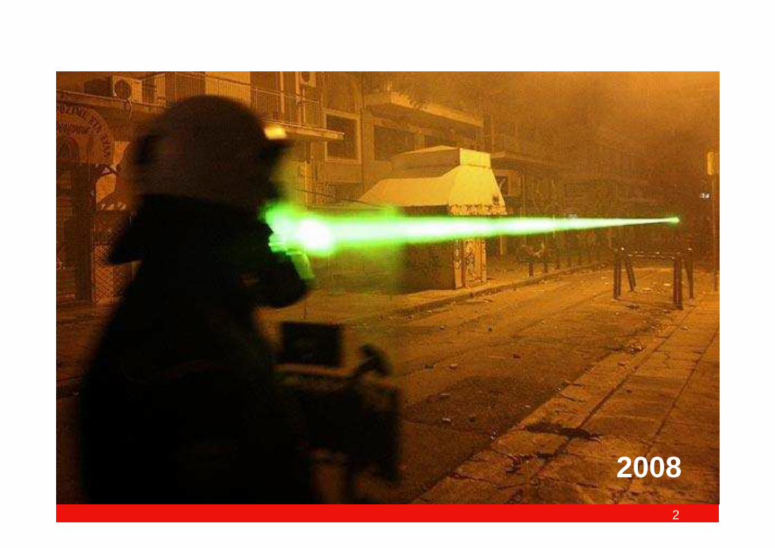
2008
3
Today’s Menu
Introduction: Laser Risks & Hazards
The science of Metamaterials, State of the art, Examples of optical filters
A novel solution: “Nano-structured thin-film Metamaterial Laser Filter”
Possible use in Civil Aviation
Conclusion - Q&A
Introduction: Laser Risks & Hazards
The science of Metamaterials, State of the art, Examples of optical filters
A novel solution: “Nano-structured thin-film Metamaterial Laser Filter”
Possible use in Civil Aviation
Conclusion - Q&A
4
Laser Pointers: Safety Hazard
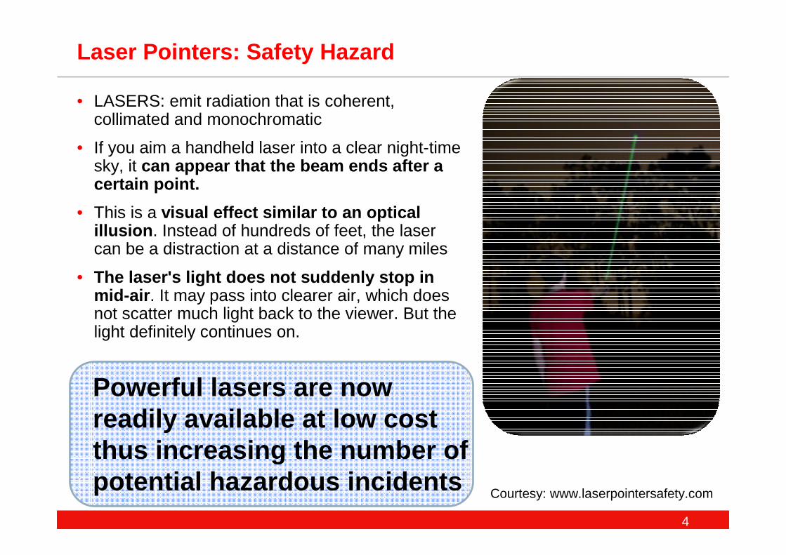
• LASERS: emit radiation that is coherent, collimated and monochromatic
• If you aim a handheld laser into a clear night-time sky, it can appear that the beam ends after a certain point.
• This is a visual effect similar to an optical illusion . Instead of hundreds of feet, the laser can be a distraction at a distance of many miles
• The laser's light does not suddenly stop in mid-air . It may pass into clearer air, which does not scatter much light back to the viewer. But the light definitely continues on.
Powerful lasers are now readily available at low cost thus increasing the number of potential hazardous incidents
Courtesy: www.laserpointersafety.com
5
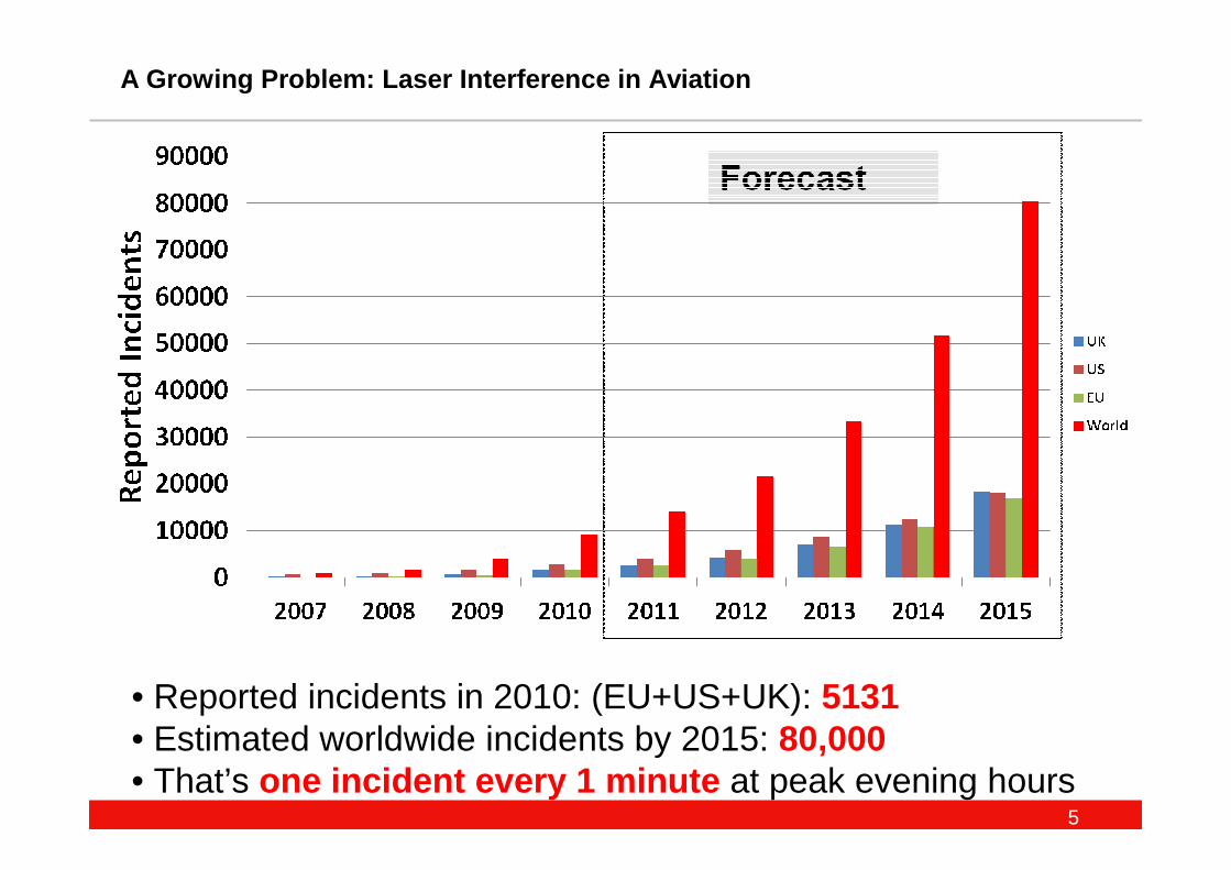
A Growing Problem: Laser Interference in Aviation
• Reported incidents in 2010: (EU+US+UK): 5131• Estimated worldwide incidents by 2015: 80,000• That’s one incident every 1 minute at peak evening hours
6
Laser Pointers: Safety Hazard
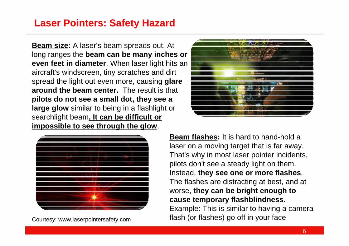
Beam flashes : It is hard to hand-hold a laser on a moving target that is far away. That's why in most laser pointer incidents, pilots don't see a steady light on them. Instead, they see one or more flashes . The flashes are distracting at best, and at worse, they can be bright enough to cause temporary flashblindness . Example: This is similar to having a camera flash (or flashes) go off in your face
Beam size : A laser's beam spreads out. At long ranges the beam can be many inches or even feet in diameter . When laser light hits an aircraft's windscreen, tiny scratches and dirt spread the light out even more, causing glare around the beam center. The result is thatpilots do not see a small dot, they see a large glow similar to being in a flashlight or searchlight beam. It can be difficult or impossible to see through the glow .
Courtesy: www.laserpointersafety.com
7
Laser Pointers: Safety Hazard
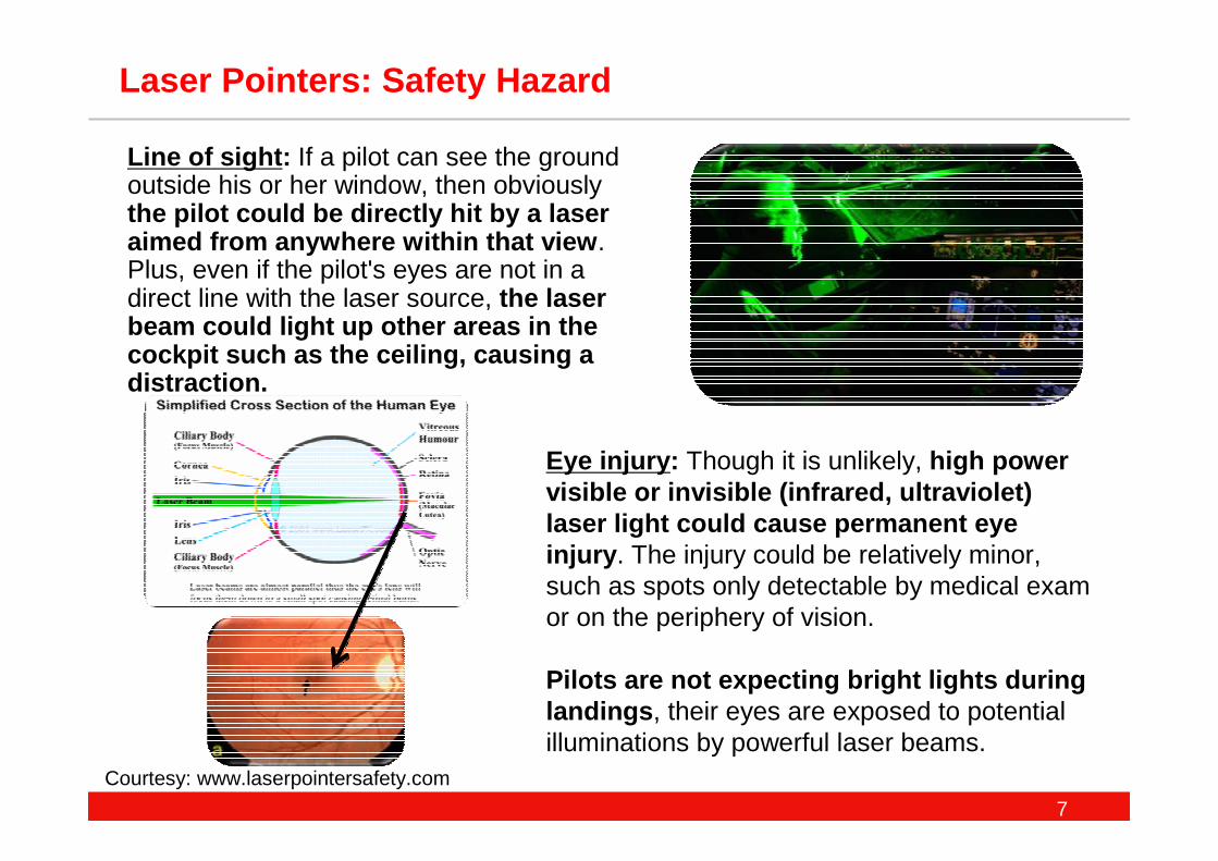
Line of sight : If a pilot can see the ground outside his or her window, then obviously the pilot could be directly hit by a laser aimed from anywhere within that view . Plus, even if the pilot's eyes are not in a direct line with the laser source, the laser beam could light up other areas in the cockpit such as the ceiling, causing a distraction.
Eye injury : Though it is unlikely, high power visible or invisible (infrared, ultraviolet) laser light could cause permanent eye injury . The injury could be relatively minor, such as spots only detectable by medical exam or on the periphery of vision.
Pilots are not expecting bright lights during landings , their eyes are exposed to potential illuminations by powerful laser beams.
Courtesy: www.laserpointersafety.com
8
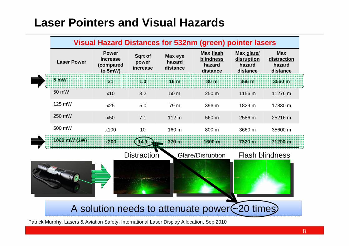
Visual Hazard Distances for 532nm (green) pointer l asers
Laser Power
Power Increase
(compared to 5mW)
Sqrt of power
increase
Max eye hazard
distance
Max flash blindness
hazard distance
Max glare/ disruption
hazard distance
Max distraction
hazard distance
5 mW x1 1.0 16 m 80 m 366 m 3560 m
50 mW x10 3.2 50 m 250 m 1156 m 11276 m
125 mW x25 5.0 79 m 396 m 1829 m 17830 m
250 mW x50 7.1 112 m 560 m 2586 m 25216 m
500 mW x100 10 160 m 800 m 3660 m 35600 m
1000 mW (1W) x200 14.1 320 m 1600 m 7320 m 71200 m
Distraction Glare/Disruption Flash blindness
Patrick Murphy, Lasers & Aviation Safety, International Laser Display Allocation, Sep 2010
Laser Pointers and Visual Hazards
A solution needs to attenuate power ~20 timesA solution needs to attenuate power ~20 times
9
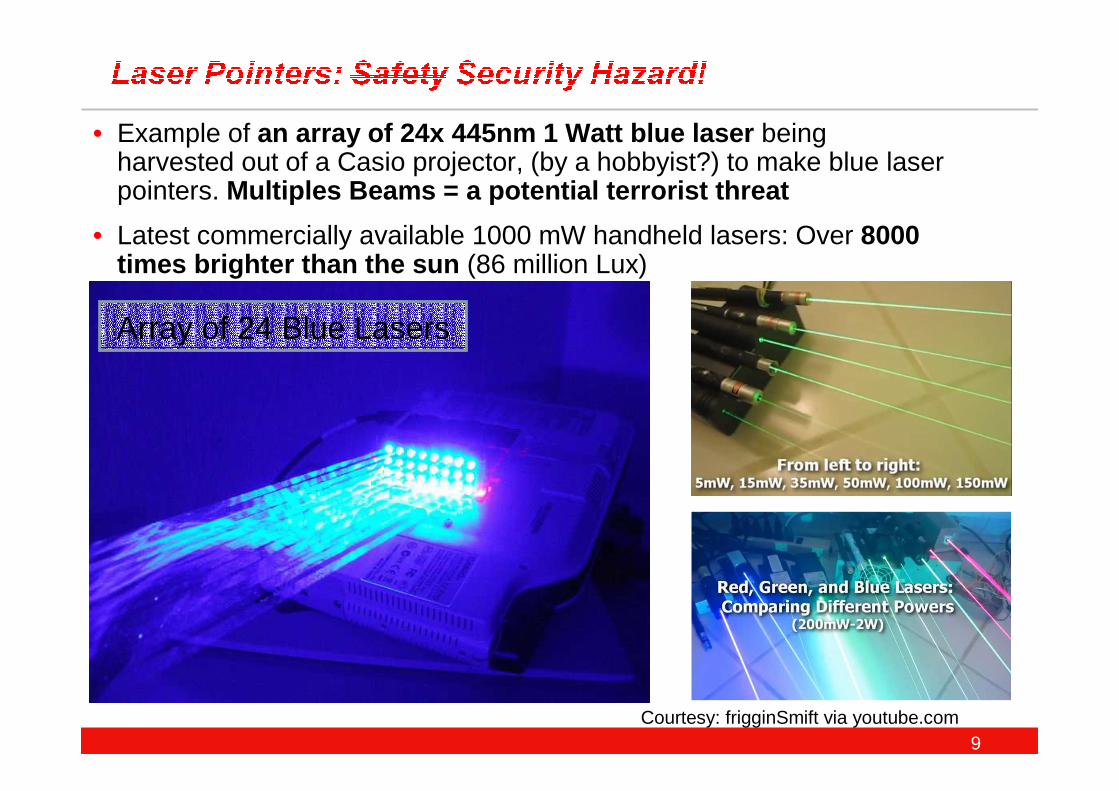
• Example of an array of 24x 445nm 1 Watt blue laser being harvested out of a Casio projector, (by a hobbyist?) to make blue laser pointers. Multiples Beams = a potential terrorist threat
• Latest commercially available 1000 mW handheld lasers: Over 8000 times brighter than the sun (86 million Lux)
Array of 24 Blue Lasers
Courtesy: frigginSmift via youtube.com
10
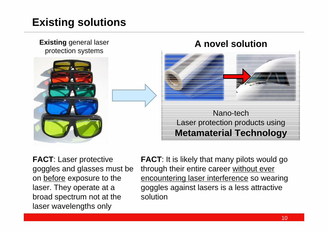
Existing solutions
Existing general laser protection systems
Nano-techLaser protection products usingMetamaterial Technology
FACT: It is likely that many pilots would go through their entire career without ever encountering laser interference so wearing goggles against lasers is a less attractive solution
FACT: Laser protective goggles and glasses must be on before exposure to the laser. They operate at a broad spectrum not at the laser wavelengths only
A novel solution
11
The Science:The Science:
MetamaterialsMetamaterials
Beyond conventional materials…
12
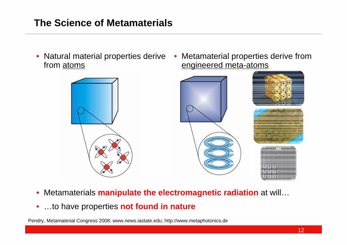
The Science of Metamaterials
Pendry, Metamaterial Congress 2008; www.news.iastate.edu; http://www.metaphotonics.de
• Natural material properties derive from atoms
• Metamaterial properties derive from engineered meta-atoms
• Metamaterials manipulate the electromagnetic radiation at will…
• …to have properties not found in nature
13
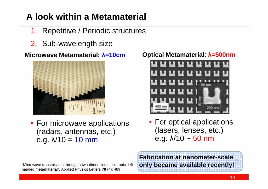
• For optical applications (lasers, lenses, etc.) e.g. λ/10 ~ 50 nm
• For microwave applications (radars, antennas, etc.) e.g. λ/10 = 10 mm
A look within a Metamaterial
"Microwave transmission through a two-dimensional, isotropic, left-handed metamaterial". Applied Physics Letters 78 (4): 489
Microwave Metamaterial: λ=10cm Optical Metamaterial : λ=500nm
1. Repetitive / Periodic structures
2. Sub-wavelength size
Fabrication at nanometer-scale only became available recently!
14
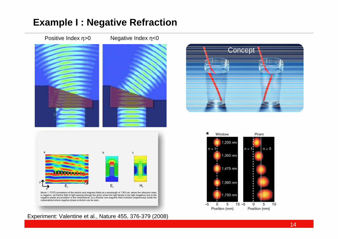
Example I : Negative Refraction
Experiment: Valentine et al., Nature 455, 376-379 (2008)
Positive Index η>0 Negative Index η<0
Concept
15
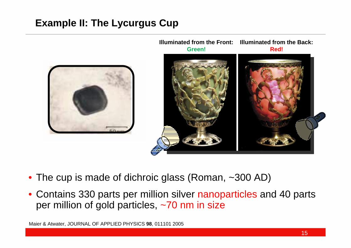
Example II: The Lycurgus Cup
• The cup is made of dichroic glass (Roman, ~300 AD)
• Contains 330 parts per million silver nanoparticles and 40 parts per million of gold particles, ~70 nm in size
Maier & Atwater, JOURNAL OF APPLIED PHYSICS 98, 011101 2005
Illuminated from the Back:Red!
Illuminated from the Front:Green!
16
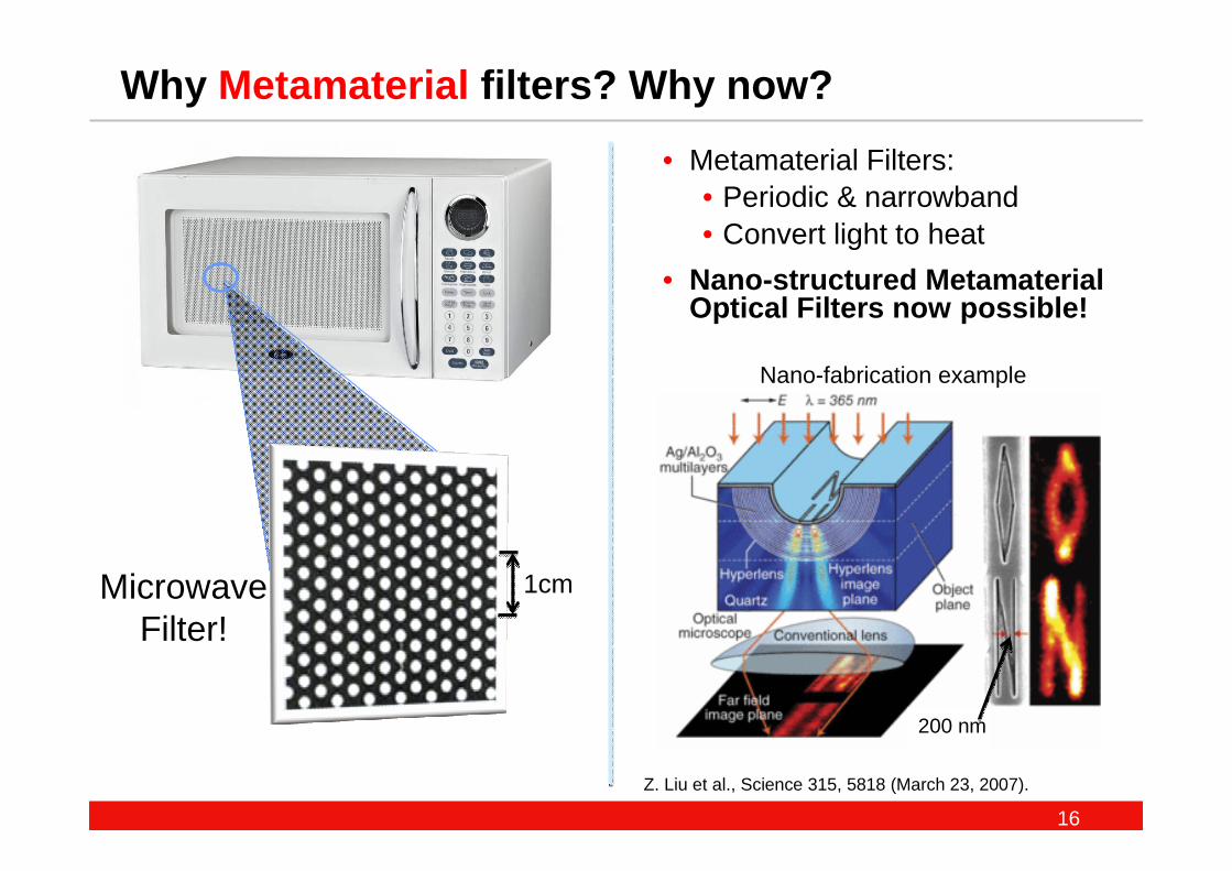
Why Metamaterial filters? Why now?
Z. Liu et al., Science 315, 5818 (March 23, 2007).
• Metamaterial Filters: • Periodic & narrowband• Convert light to heat
• Nano-structured Metamaterial Optical Filters now possible!
MicrowaveFilter!
Nano-fabrication example
1cm
200 nm
17
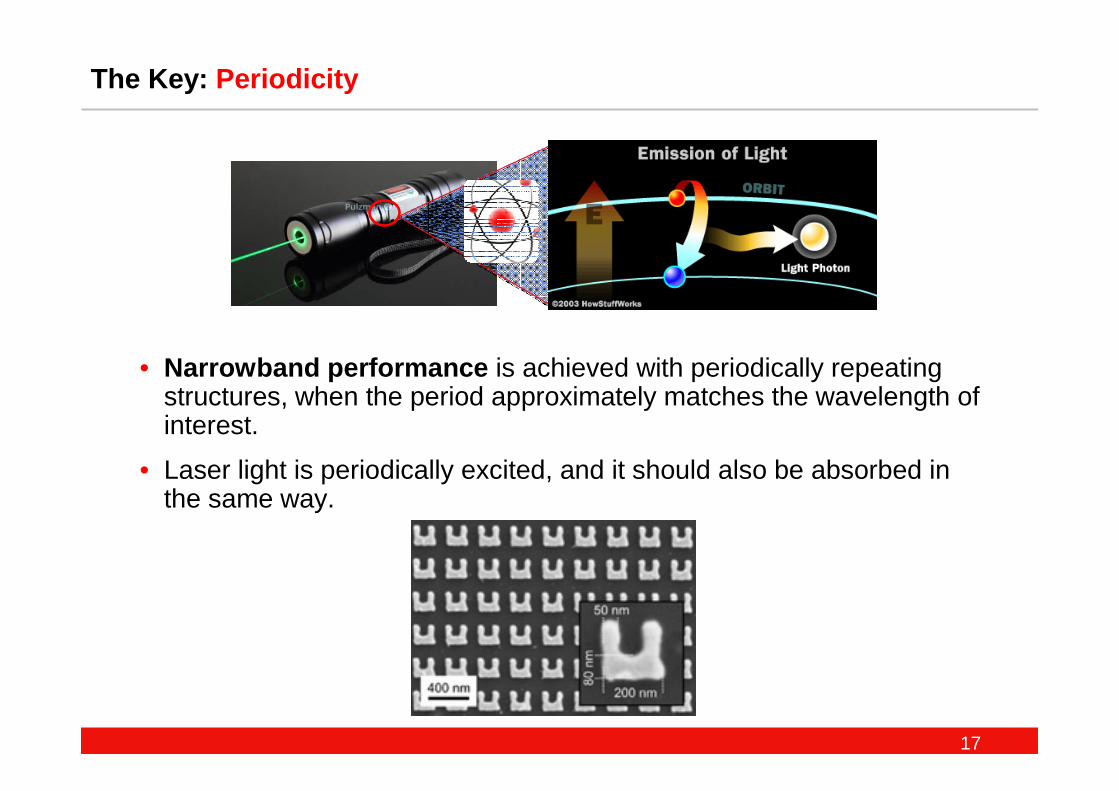
The Key: Periodicity
• Narrowband performance is achieved with periodically repeating structures, when the period approximately matches the wavelength of interest.
• Laser light is periodically excited, and it should also be absorbed in the same way.
18
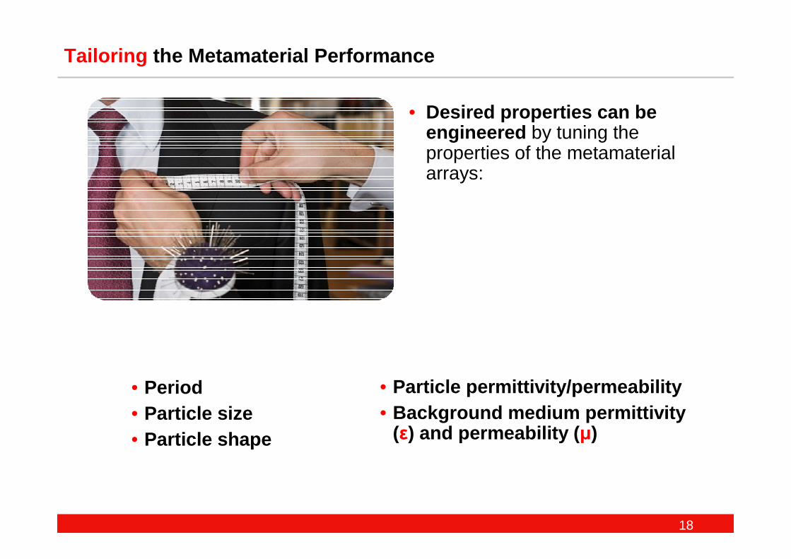
Tailoring the Metamaterial Performance
• Desired properties can be engineered by tuning the properties of the metamaterial arrays:
• Particle permittivity/permeability• Background medium permittivity
(ε) and permeability ( µ)
• Period• Particle size• Particle shape
19
Developing an optimal solution:Developing an optimal solution:
Metamaterial Nano-particles
20
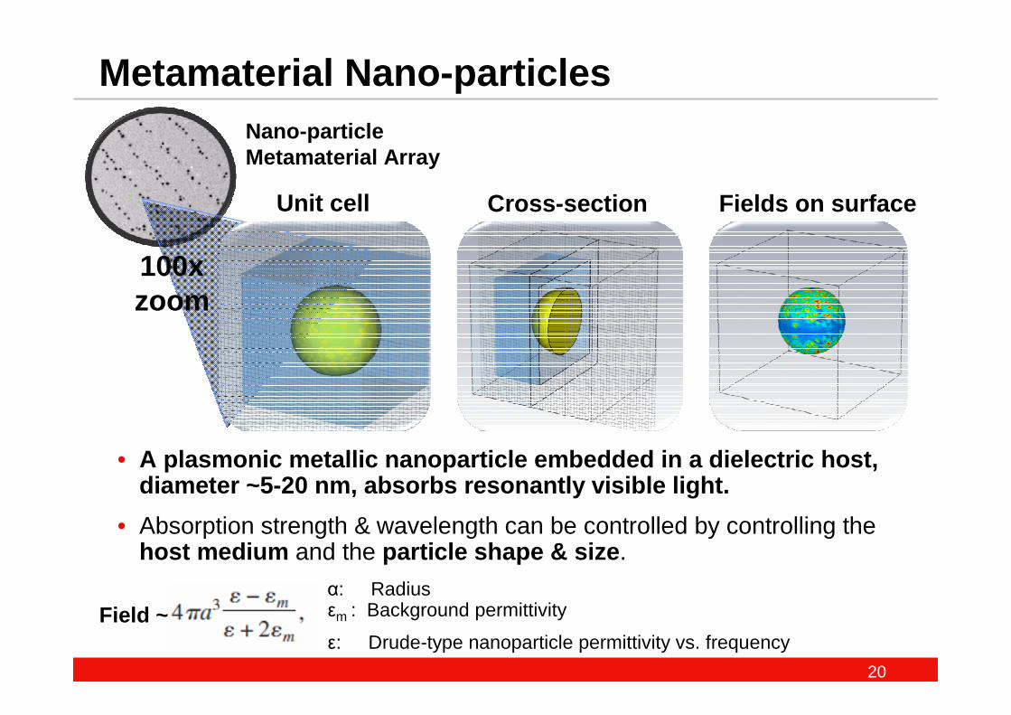
Metamaterial Nano-particles
• A plasmonic metallic nanoparticle embedded in a diel ectric host,diameter ~5-20 nm, absorbs resonantly visible light.
• Absorption strength & wavelength can be controlled by controlling the host medium and the particle shape & size .
Cross-section Fields on surface
α: Radiusεm : Background permittivity
ε: Drude-type nanoparticle permittivity vs. frequencyField ~
Nano-particle Metamaterial Array
Unit cell
100x zoom
21
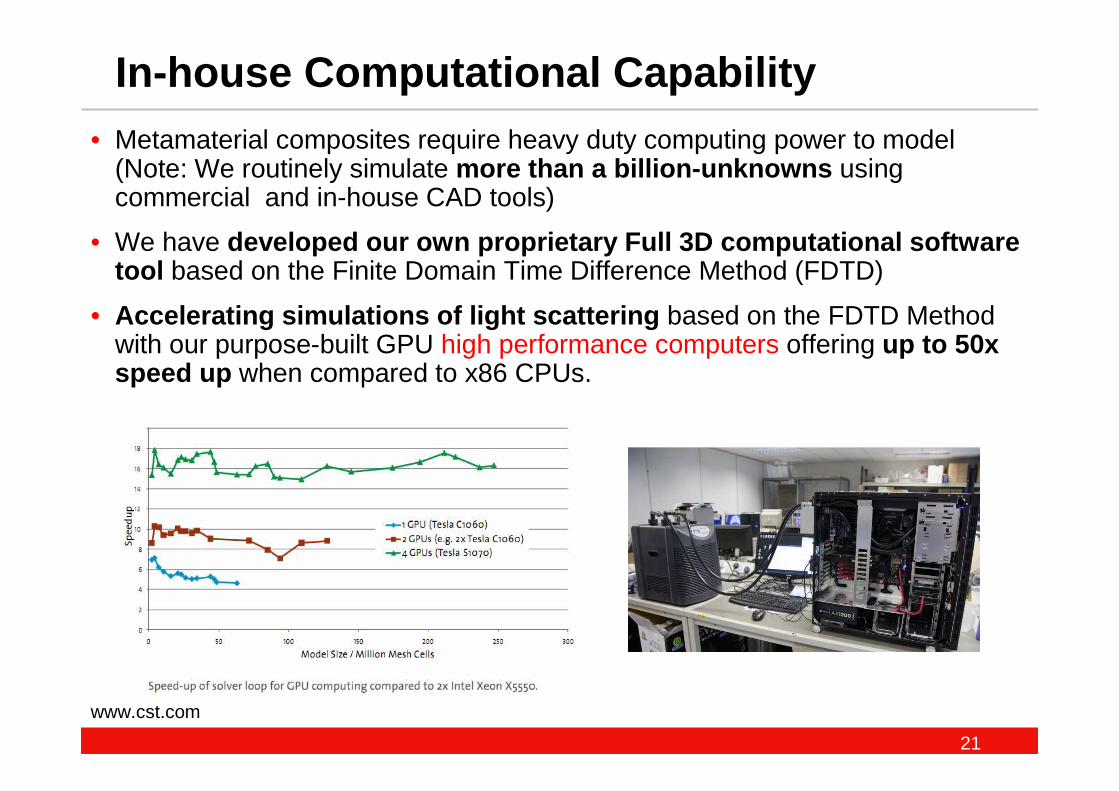
• Metamaterial composites require heavy duty computing power to model (Note: We routinely simulate more than a billion-unknowns using commercial and in-house CAD tools)
• We have developed our own proprietary Full 3D computational sof tware tool based on the Finite Domain Time Difference Method (FDTD)
• Accelerating simulations of light scattering based on the FDTD Method with our purpose-built GPU high performance computers offering up to 50x speed up when compared to x86 CPUs.
In-house Computational Capability
www.cst.com
22
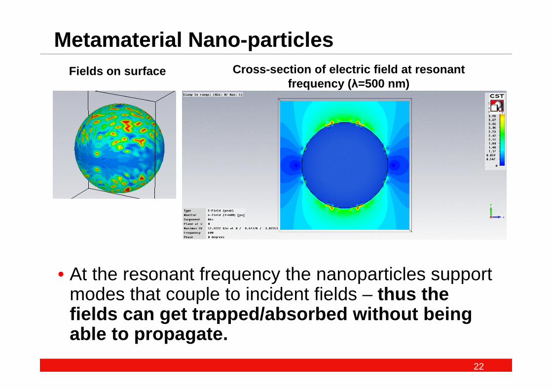
Metamaterial Nano-particles
• At the resonant frequency the nanoparticles support modes that couple to incident fields – thus the fields can get trapped/absorbed without being able to propagate.
Fields on surface Cross-section of electric field at resonant frequency ( λ=500 nm)
23
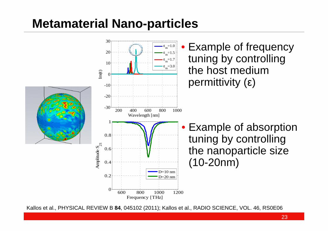
Metamaterial Nano-particles
• Example of frequency tuning by controlling the host medium permittivity (ε)
200 400 600 800 1000-30
-20
-10
0
10
20
30
Wavelength [nm]
Im(ε
)
εm
=1.0
εm
=1.5
εm
=1.7
εm
=3.0
600 800 1000 12000
0.2
0.4
0.6
0.8
1
Frequency [THz]
Am
plitu
de S
21
D=10 nmD=20 nm
• Example of absorption tuning by controlling the nanoparticle size (10-20nm)
Kallos et al., PHYSICAL REVIEW B 84, 045102 (2011); Kallos et al., RADIO SCIENCE, VOL. 46, RS0E06
24
Proposed use in Civil AviationProposed use in Civil Aviation
25
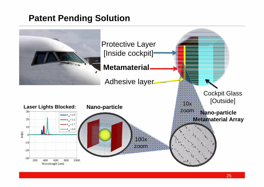
Nano-particle Metamaterial Array
Patent Pending Solution
Protective Layer[Inside cockpit]
Metamaterial
Adhesive layer
Cockpit Glass[Outside]10x
zoomNano-particle
100x zoom
200 400 600 800 1000-30
-20
-10
0
10
20
30
Wavelength [nm]
Im(ε
)
εm=1.0
εm=1.5
εm=1.7
εm=3.0
Laser Lights Blocked:
26
Technology Summary
Critical technology goals: • Thin-film power attenuator (band-stop) filters at multiple
optical laser wavelengths • e.g. 532nm-green wavelength, 633nm-red wavelength, etc.
• Narrowband performance• Need for resonant & periodic structures: Metamaterials!
• Structures that enable optically clear / transparent end-product• Materials that are otherwise difficult to achieve with the desired
combination of properties
First Prototypes in Q1, 2012
27
Summary
• Civil Aviation is currently facing a rapidly increasing problem with potential Safety & Security hazards .
• Lasers and becoming cheaper and more powerful, readily available worldwide.
• We designed a patent pending solution , i.e. novel optical Metamaterial filters that will prevent laser interference(recently established Lamda Guard Ltd )
• These filters are nano-structured thin films, easy to deploy.
• These filters will be applied to aircraft cockpit windscreens and ATC tower windows in order to selectively block light from laser interference which distracts personnel during critical phases of flight.
29
Backup slides
30
LAMDA GUARD LTD.
London, UK
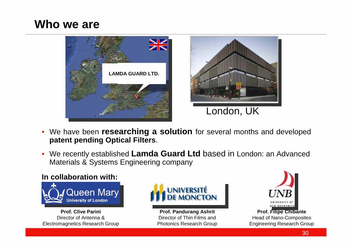
Who we are
• We have been researching a solution for several months and developed patent pending Optical Filters .
• We recently established Lamda Guard Ltd based in London: an Advanced Materials & Systems Engineering company
In collaboration with:
Prof. Clive PariniDirector of Antenna &
Electromagnetics Research Group
Prof. Pandurang Ashrit Director of Thin Films and Photonics Research Group
Prof. Filipe Chibante Head of Nano-Composites
Engineering Research Group
31
A Growing Problem: Laser Interference in Aviation
• In the last 3-5 years, Aviation Authorities worldwide are reporting an exponential increase in the number of incidents in which aircrafts are targeted by hand-held pointer lasers.
• These attacks are a serious safety issue as lasers can damage pilots’eyes and cause temporary blindness during critical phases of flight such as take-off, landing, and emergency manoeuvres.
• There is also concern that terrorists may use an array of lasers to distract pilots potentially leading to a disaster.
• Reported Laser attacks include: airplanes, helicopters and ATC towers
• This issue has become so serious that, new CAN/US/UK/Australia laws were introduced making it a criminal offence to shine laser beams at aircraft.
• Existing solutions are not effective and include laser safety goggles, glare shields, and reflectors which cause discomfort, do not usually cover more than one wavelength, and interfere with night-time vision and cockpit indicators
32
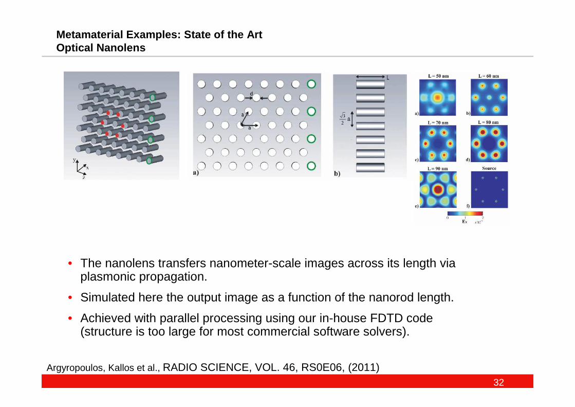
Metamaterial Examples: State of the Art Optical Nanolens
Argyropoulos, Kallos et al., RADIO SCIENCE, VOL. 46, RS0E06, (2011)
• The nanolens transfers nanometer-scale images across its length via plasmonic propagation.
• Simulated here the output image as a function of the nanorod length.
• Achieved with parallel processing using our in-house FDTD code (structure is too large for most commercial software solvers).
33
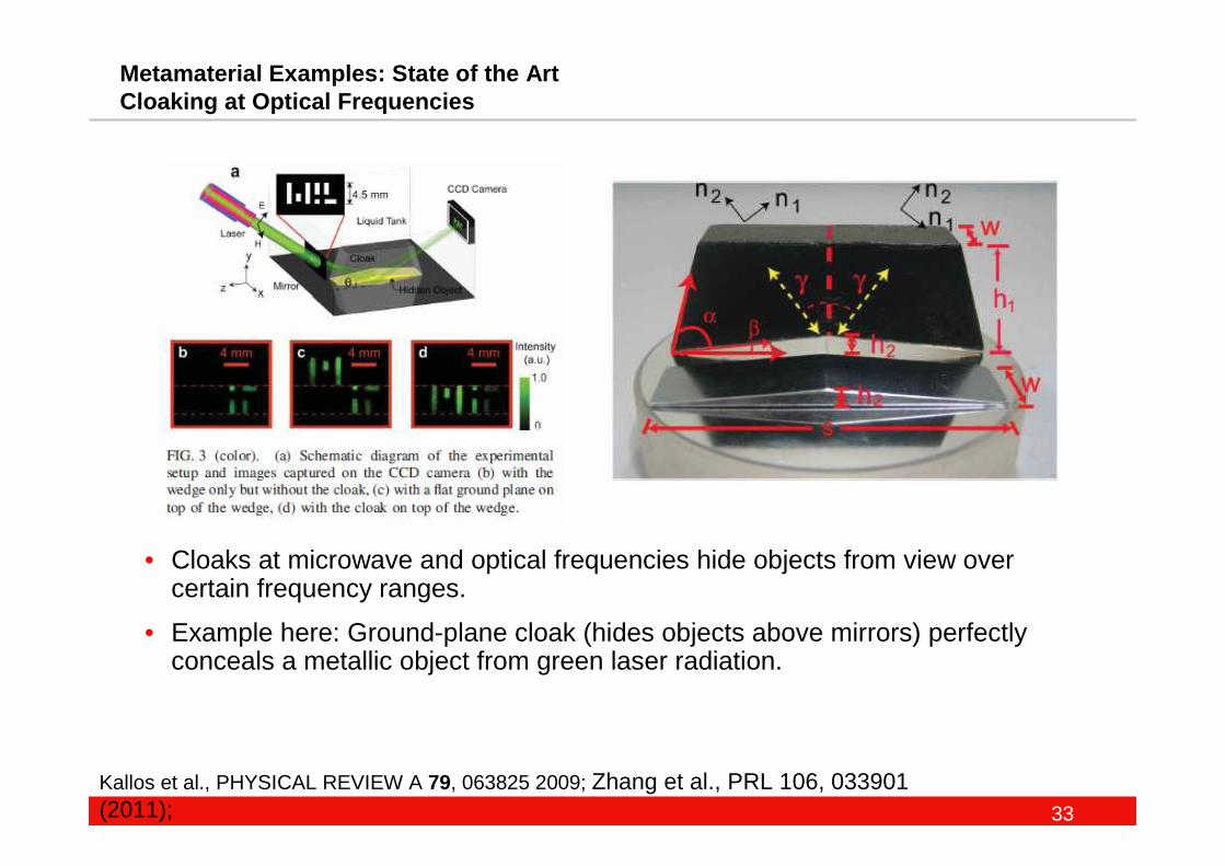
Metamaterial Examples: State of the Art Cloaking at Optical Frequencies
Kallos et al., PHYSICAL REVIEW A 79, 063825 2009; Zhang et al., PRL 106, 033901 (2011);
• Cloaks at microwave and optical frequencies hide objects from view over certain frequency ranges.
• Example here: Ground-plane cloak (hides objects above mirrors) perfectly conceals a metallic object from green laser radiation.
34
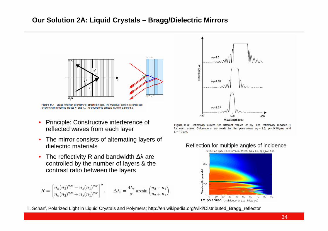
Our Solution 2A: Liquid Crystals – Bragg/Dielectric Mirrors
T. Scharf, Polarized Light in Liquid Crystals and Polymers; http://en.wikipedia.org/wiki/Distributed_Bragg_reflector
• Principle: Constructive interference of reflected waves from each layer
• The mirror consists of alternating layers of dielectric materials
• The reflectivity R and bandwidth ∆λ are controlled by the number of layers & the contrast ratio between the layers
Reflection for multiple angles of incidence
35
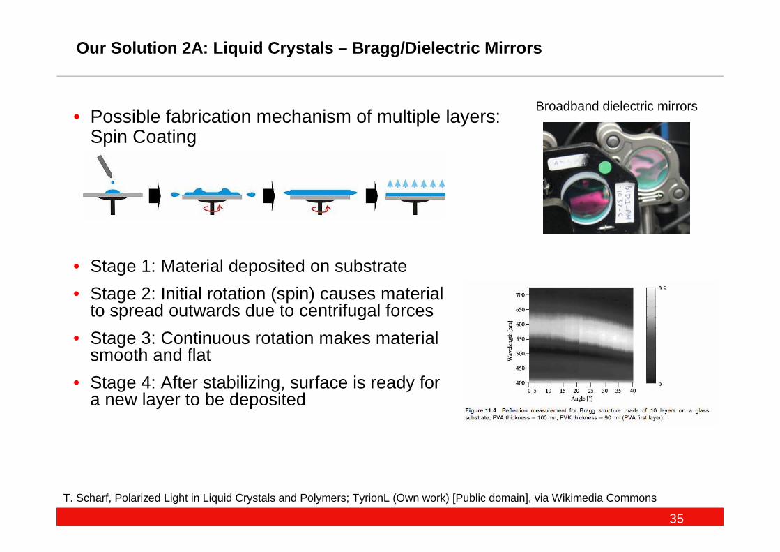
Our Solution 2A: Liquid Crystals – Bragg/Dielectric Mirrors
T. Scharf, Polarized Light in Liquid Crystals and Polymers; TyrionL (Own work) [Public domain], via Wikimedia Commons
• Possible fabrication mechanism of multiple layers: Spin Coating
Broadband dielectric mirrors
• Stage 1: Material deposited on substrate
• Stage 2: Initial rotation (spin) causes material to spread outwards due to centrifugal forces
• Stage 3: Continuous rotation makes material smooth and flat
• Stage 4: After stabilizing, surface is ready for a new layer to be deposited
36
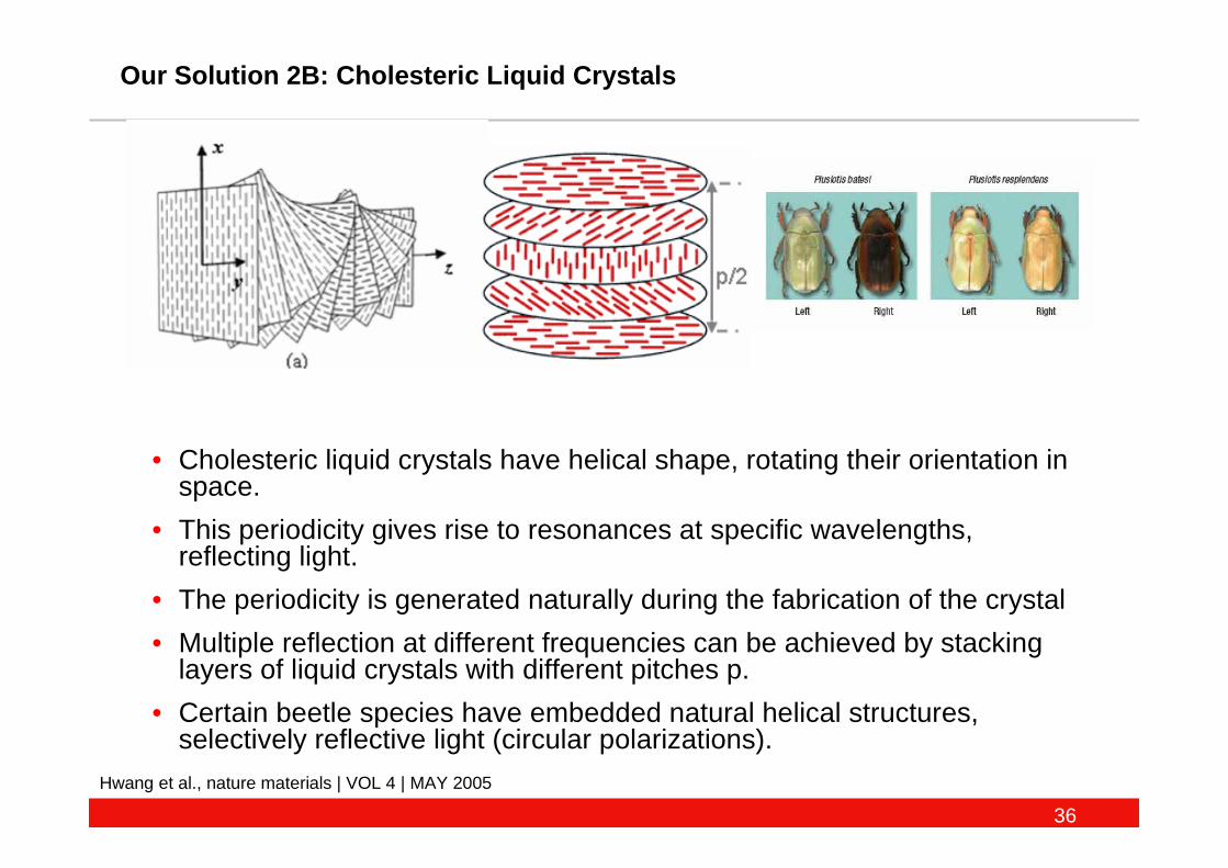
Our Solution 2B: Cholesteric Liquid Crystals
Hwang et al., nature materials | VOL 4 | MAY 2005
• Cholesteric liquid crystals have helical shape, rotating their orientation in space.
• This periodicity gives rise to resonances at specific wavelengths, reflecting light.
• The periodicity is generated naturally during the fabrication of the crystal
• Multiple reflection at different frequencies can be achieved by stacking layers of liquid crystals with different pitches p.
• Certain beetle species have embedded natural helical structures,selectively reflective light (circular polarizations).
37
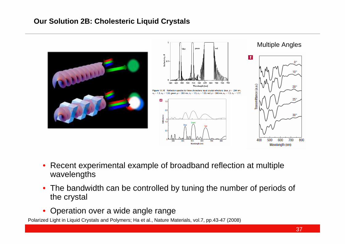
Our Solution 2B: Cholesteric Liquid Crystals
Polarized Light in Liquid Crystals and Polymers; Ha et al., Nature Materials, vol.7, pp.43-47 (2008)
• Recent experimental example of broadband reflection at multiple wavelengths
• The bandwidth can be controlled by tuning the number of periods of the crystal
• Operation over a wide angle range
Multiple Angles
38
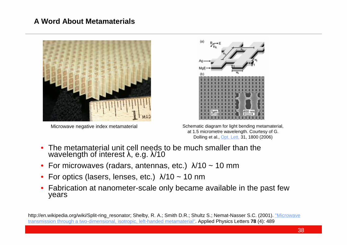
A Word About Metamaterials
http://en.wikipedia.org/wiki/Split-ring_resonator; Shelby, R. A.; Smith D.R.; Shultz S.; Nemat-Nasser S.C. (2001). "Microwave transmission through a two-dimensional, isotropic, left-handed metamaterial". Applied Physics Letters 78 (4): 489
• The metamaterial unit cell needs to be much smaller than the wavelength of interest λ, e.g. λ/10
• For microwaves (radars, antennas, etc.) λ/10 ~ 10 mm• For optics (lasers, lenses, etc.) λ/10 ~ 10 nm• Fabrication at nanometer-scale only became available in the past few
years
Schematic diagram for light bending metamaterial, at 1.5 micrometre wavelength. Courtesy of G.
Dolling et al., Opt. Lett. 31, 1800 (2006)
Microwave negative index metamaterial