n94-34190 - nasa · pdf filen94-34190 a review of vibration problems ... paper reviews a...
TRANSCRIPT
N94- 34190
A REVIEW OF VIBRATION PROBLEMS IN POWER STATION BOILER FEED PuMPs
David France
Weir Pumps Limited
Glasgow, Scotland
SYNOPSIS f
/k
Boiler Feed Pump reliability and availability is recognised as important to the overall efficiencyof power generation. Vibration monitoring is often used as part of planned maintenance. This
paper reviews a number of different types of boiler feed pump vibration problems describing
some methods of solution in the process. It is hoped that this review may assist both designersand users fac_ with similar problems.
/
1.0 INTRODUCTION
The reliability of the boiler feed pump in modem power stations is seen as essential to ensure
the overall availability of the power generating plant and is often included in the rotatingmachinery vibration monitoring programme practised by many power station maintenance
departments. The vibration characteristics of a boiler feed pump earl be complex and difficult
to understand and it is the purpose of this paper to describe typical vibration mechanisms at
work to assist those engaged in the diagnosis of problems. Case studies are presented whichdemonstrate the following types of vibration responses:-
1. Forced
2. Resonant
3. Self excited
4. Transient
5. Cavitation
Some solutions to these are described in the hope that these may assist both designers and usersfaced with similar problems.
2.0 FORCED VIBRATIONS
Forced vibrations - vibrations which are produced by the application of an external set ofoscillatory forces.
Centrifugal pump vibrations are often described as being either synchronous or non-
synchronous with respect to its operating speed. Usually synchronous is taken to mean the
vibration component at the pump's operating speed although it is often taken to include anyharmonic of this. Nonsynchronous covers all other frequency components. Synchronousforcing influences may arise from either mechanical or hydraulic sources of unbalance.
Mechanical sources are fairly well understood because of the general similarity in other types
of rotating equipment. Hydraulic sources may result from either casting asymmetries or partial
249
https://ntrs.nasa.gov/search.jsp?R=19940029684 2018-04-20T13:52:58+00:00Z
blockage of impeller passageways by, for example, ingress of foreign matter. Generally
speaking the magnitude of hydraulic unbalance generated by an impeller is greater than the
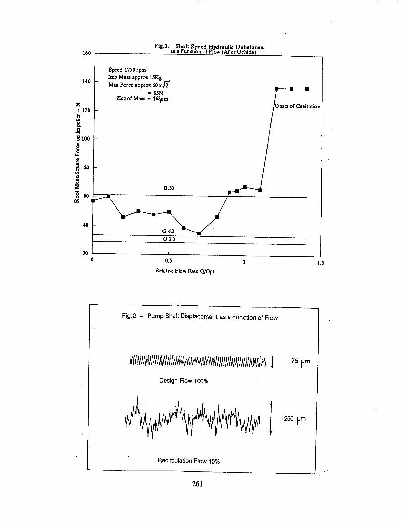
residual mass unbalance component. A Japanese investigator, ref. 1, measured the hydraulic
force as a function of flowrate, fig. 1. The maximum value of unbalance qualities of G2.5 -
G6.3. Practical experience suggests that precision castings for the impellers of high speed feed
pumps could offer a hydraulic reduction of possibly an order of magnitude. Nonsynchronous
forced responses usually arise at part load operations where hydraulic forces, generated by
recirculating flows within the impeller or diffuser, may give rise to irregular or cyclic low
frequency excitations. These have been discussed previously by a number of authors, ref.2, 3.
A t3,pical example of this can be seen in fig.2, where the shaft displacement increased threefold
between the design flowrate and the recirculation flow quantity.
Substantial forces may be generated due to interaction of the impeller blades with guide vanes
in either the upstream or downstream flow fields. These forces manifest themselves as
vibration at the impeller blade number and blade number harmonics. The main area of concern
to any maintenance engineer is undoubtedly the effect that high blade vibration levels may haveon the reliability of the pump. Understandably the worry is whether or not this may result in a
fatigue failure of impeller or diffuser. General machinery vibration guidelines offer little help
in this regard except to suggest that vibration monitoring may help to identify deterioration.Data from the field serve to illustrate the difficulties of interpretation further. For example,
blade vibration levels of 15mm/see rms are not untypical on some of our boiler feed pumps yet
these pumps have given many years of trouble free operation. On the other hand, impellerblade or impeller shroud failures have occurred after some 6 months to 2 years into operation
yet external levels of blade vibration have been less than 2mm/see rms. Clearly, therefore,
there is not necessarily a one - one relationship between vibration level and the stress levels
within the working components. Insight into generation of vibration at blade frequency and
blade frequency harmonies results from the studies by Zotov, ref.4, this theory shows that it is
possible to select impeller and diffuser blade number combinations to suppress the vibration atthe fundamental blade frequency, or if required, at a higher blade frequency harmonic. This is
indicated by the values shown in Table I. The table shows the radial vibration force frequency
components relative to a unit magnitude radial interaction force between each of the impellerand diffuser blades. It is significant that the vibration of the pump casing can be minimised in
this way, but care is needed to ensure that certain blade combinations do not give rise to
reinforced pressure fluctuations in the fluid as could be the case with 6 x 9, and 8 x 12 blade
combinations. Experimental data obtained from pumps with 7 x 12 and 7 x 13 bladecombinations show encouraging correlation with theory, these also are given inTable I.
Although blade numbers can have a powerful effect on the distribution of the harmonic contentof the resultant blade interaction forces, the stresses induced on the individual blades are not
significantly modified by the number of blades between the impeller and diffuser. The
magnitude of the interaction forces are influenced by the hydraulic design, the stage power, the
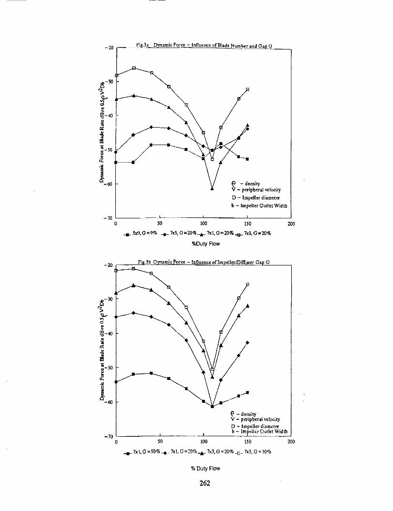
impeller to diffuser gap, the operating point relative to the best efficiency point and possibly the inlet
guide vane geometry and upstream flow field. It seems fairly well accepted that a minimum tip
gap of 3% of impeller radius, (derived empirically by Makay, ref.5.), is sensible to avoid
highly stressed components. Some results of research by Weir Pumps Limited into bladecombinations and tip gaps give interesting insight into such effects, fig.3a, 3b.
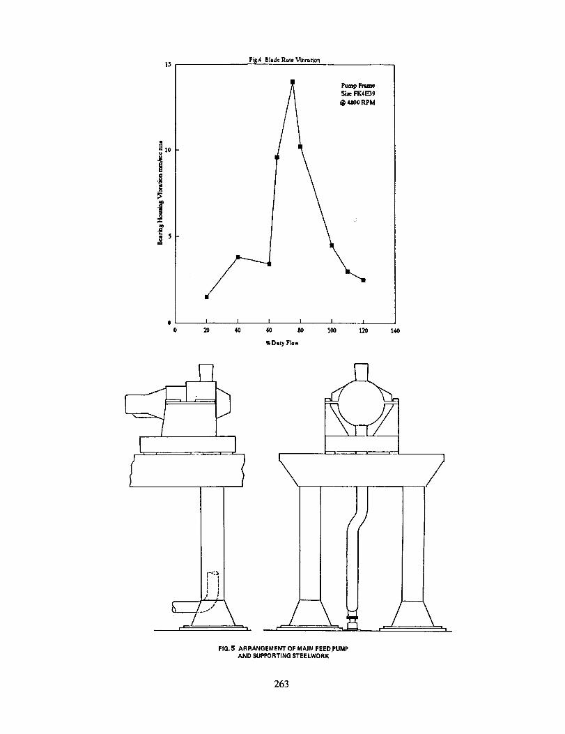
In 1985 an unusual blade vibration phenomenon was identified on a number of boiler feed
pumps destined for an East European power station. The pumps are 4 stage boiler feed driven
by steam turbines. Pump design duty is 0.36m3/sec at 2461m head at 5454 rpm, impellerblade number is 7 and diffuser number is 12. Tip gap is 3%. This should have resulted in low
25O
blade rate vibration levels, yet high vibration levels were experienced on some of the pumps on
the drive end bearing housing only. The vibration was only experienced over a narrow range of
flow. A typical blade frequency vibration characteristic is shown in fig.4. Each pump showedsimilar characteristics but the vibration level on some of the pumps was only about 2.0 -
3.0mm/sec rms. Despite many hours of tests and subsequent examinations of components
from a number of pumps, it was not possible to ascertain any difference which might explain
the variation in vibration level. The only modification done was to eliminate the upstream inlet
guide vanes to the first stage impeller, this had no effect on the magnitude of the vibration. The
problem source has never properly been identified, yet the vibration levels would appear not tobe detrimental to reliability as the pumps have been operating satisfactorily for more than sixyears.
3.0. RESONANT VIBRATIONS
Resonance - a phenomenon evident when the frequency of the disturbing force equals a naturalfrequency of the system.
In 1982 a resonance problem was experienced on a four turbine driven variable speed boilerfeed pump, installed at Huntly Power Station, (4 x 250MW), New Zealand. The area is
seismically active and the design of the pump and turbine support structure reflected the
selsm_c requirements. The pump was centre hne mounted on a baseplate which was secured to
a large steel table onto which the turbine was also mounted. The steel table was supported
from the floor level by a number of tall vertical metal columns, ensuring a low frequency
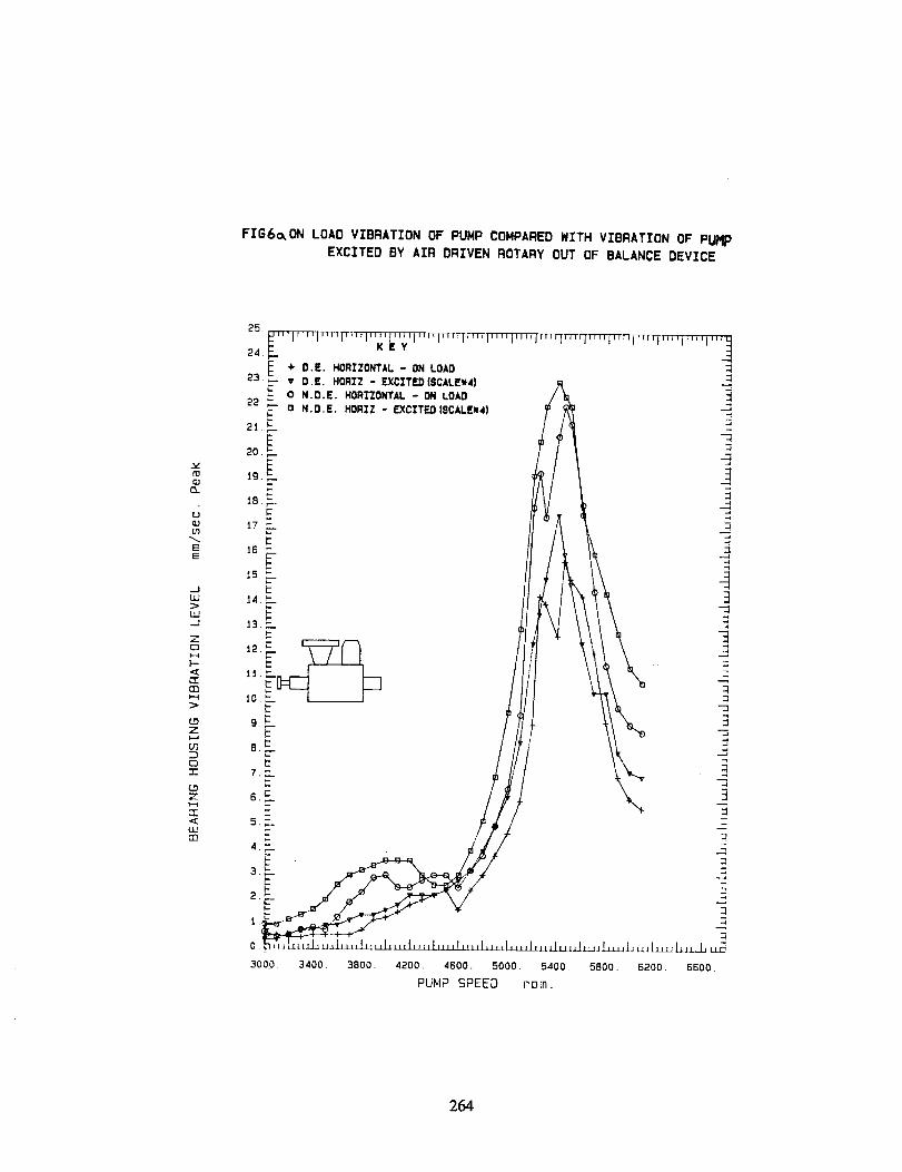
mounting system for the equipment. A schematic is shown if fig.5. High vibration levels, in
excess of 20mm/sec peak, at pump shaft frequency, were obtained at generator loading of 200-220MW, corresponding to a pump speed in the range 5300 rpm-5500rpm. Examination of the
amplitude phase relationship suggested a resonance was responsible. Excitation tests werecarried out with the pump stationary using an air driven rotary out of balance exciter to
stimulate the structure into vibration and to examine the mode shape. These tests confirmed
there was a natural frequency of the pump, but the mode shape was complcx shossing motioninvolving the pump and turbine support structure. Surprisingly, thcrc was little or no
deformation of the pump casing and pump supporting baseplate, the whole body appeared to
bc moving on the flexibility of the steel supports beneath the base plate. A comparison of theon load vibration characteristic compared with the vibration obtained from the air driven
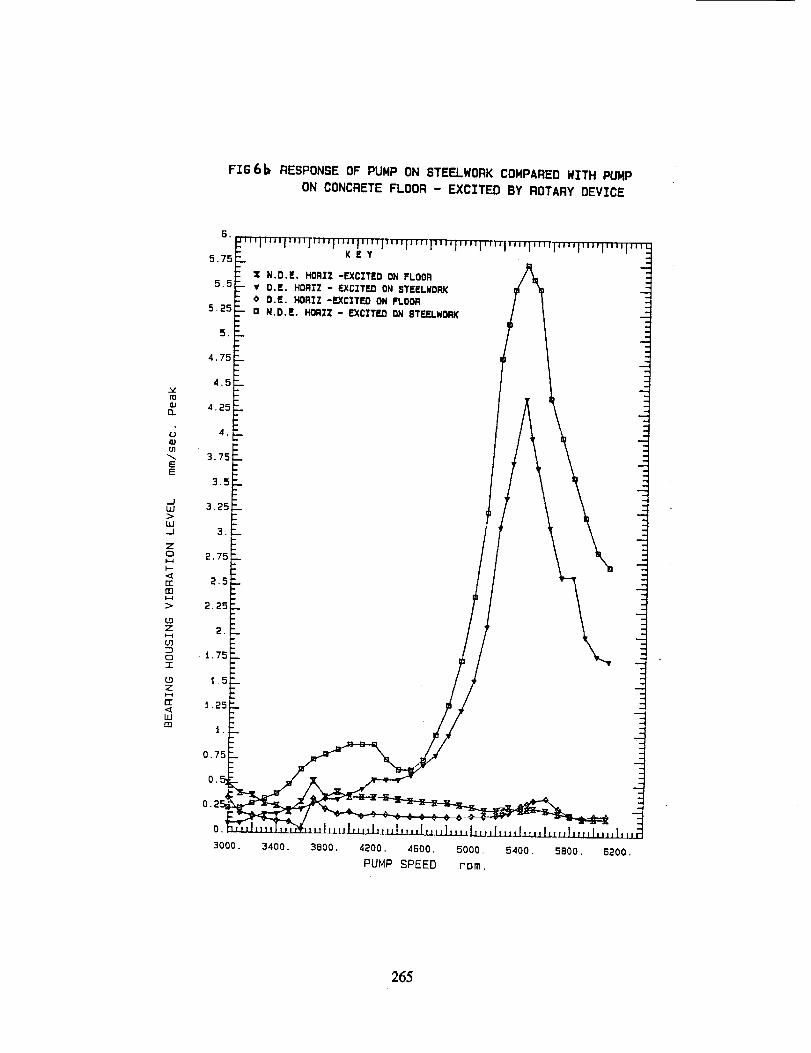
exciter is shown in fig.6a. Exciter tests were then carried out with one of the pumps and itsbaseplate secured to a concrete foundation. No evidence of any natural frequencies in the
range 3000emp - 6000epm were found indicating that the steel support structure was importantin terms of the mode of vibration of concern. A comparison of the responses on the steelwork
and on the concrete floor are shown in fig.6b. The next stage of this investigation was to
consider how detuning the resonant frequency could be achieved on site. Clearly a solid
support for the pump bedplate would have solved the problem but it was impractical to stiffen
the support steelwork sufficiently. It was decided to introduce compliance between the pumpcasing and the bedplate at the pump support feet. As designed the support feed slide relative to
the pump baseplate on greased brass pads to accommodate thermal expansion. A modification
was made as shown in fig.7, this introduced horizontal flexibility but still allowed the pumpsupport feet to slide. On site a series of exciter experiments was carried out to optimise the
flexibility of the detuning element. Once an optimum was found the pump was run up to fidlload to demonstrate the modification. The vibration levels were found to be a maximum of
5ram/see peak. A comparison before and after modification is shown in fig.8.
251
4.0 SELF EXCITED VIBRATIONS
Self excitation - vibrations which are caused by disturbing forces which result from feedback
from the motion of the vibrating object itself.
A review of self excited vibrations in centrifugal pumps has been presented in ref.6. This
paper discusses a wide variety of types including the "near running speed" nonsynchronousvibrations reported by a number of authors. There have been only a few reported examples
with boiler feed pumps, and then mainly outside the UK.
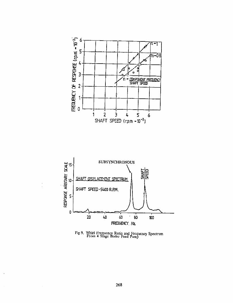
In the late sixties a 0.8 x running speed vibration problem was found on starting and standby
boiler feed pumps at Longannct Power Station, Scotland. The high vibrations were seen over a
range of operating speed from 3500 rpm - 6000 rpm as shown in fig.9. The pump was found
to undergo an almost instantaneous progression from low level synchronous vibration to"foundation shaking" nonsynchronous vibration as pump speed was increased; typical of a
classical self excited vibration phenomenon. The problem was related to premature wear out
of the pumps internal clearances caused by intermittent low flow opcration and consequentialreduction in rotor stiffness. The problem was eliminated by increasing the minimum
rceirculating flow to eliminate the wear out problem; no further research was done at this time
on xshat was believed to a "one off" phenomenon.
In 1978 serious problems were experienced during works testing of three pumps. Performance
tests were conducted at full power and fixed speed and near running speed subsynchronous
vibration was experienced. These pumps were 7 stage pumps absorbing 2230Kw at 5850 rpm.
The problem was first noticed as flowrate was increased from the minimum recirculation
quantity to the design flow. Shaft probes were fitted as standard and the transition from
synchronous to nonsynchronous vibration was abrupt. It was also established that reducing
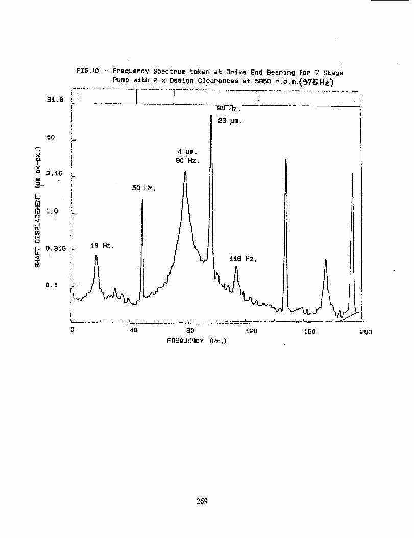
flowrate could once again stabilise the pump. Shaft displacement levels were 751am pk-pk at a
frequency of 80Hz-g4Hz giving a whirl frequency ratio of 0.82-0.86. A typical average
spectrum is shown in fig. 10. A 24 hour endurance test on the test bed confirmed the severity of
the problem when balance drum leakage flowrates doubled and bearing housing vibrationsincreased fourfold. Initially it was assumed that the problem was a classical rotor instability,
i.e. unstable eigenvalue. It was believed that negative stiffness and forward driving cross
coupling could arise due to an impcUer/diffuscr interaction of the type described in (11).
However, it seemed unlikely that the problem was due to an unstable cigenvahie as
rotordynamic analysis predicted well damped eigenvalues even with generous allowances for
impeller/diffuser interaction forces. Nevertheless, both aspects of the problem were examined,the formcr by a specially instrumented single stage test rig and the latter by conducting variable
speed tests on one of the pumps with clearances set at design values (0.5mm) and then twice
design (lmm). To assist the problem diagnosis a pair of displacement probes were installed toview the shaft motion at the balance drum as well as the bearings of the pump. The results of
these tests are summarised in fig. 1la and fig. 1 lb. Tracking of the amplitude and phase of the
synchronous component of shaft vibration over a speed range from 4000 rpm - 6500 rpmshowed no significant phase or amplitude change which would indicate even a near proximity
to a natural frequency. A similar result was obtained for both the design and twice design
clearances build configurations. Rotordynamic calculations confirmed the shaft motion and
phase measurements at the balance drum and bearings and absence of unstable eigenvalues.Of cnormous significance was the fact that the subsynchronous component of vibration bore an
almost fixed ratio with respect to speed (.85) for both clearance cases tested. The
subsynchronous component was discernible down to the minimum speed tested. The test rig
252
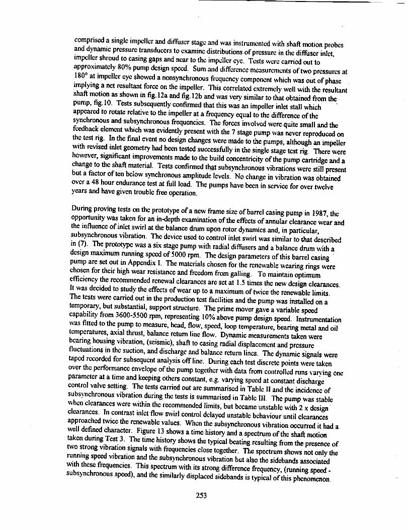
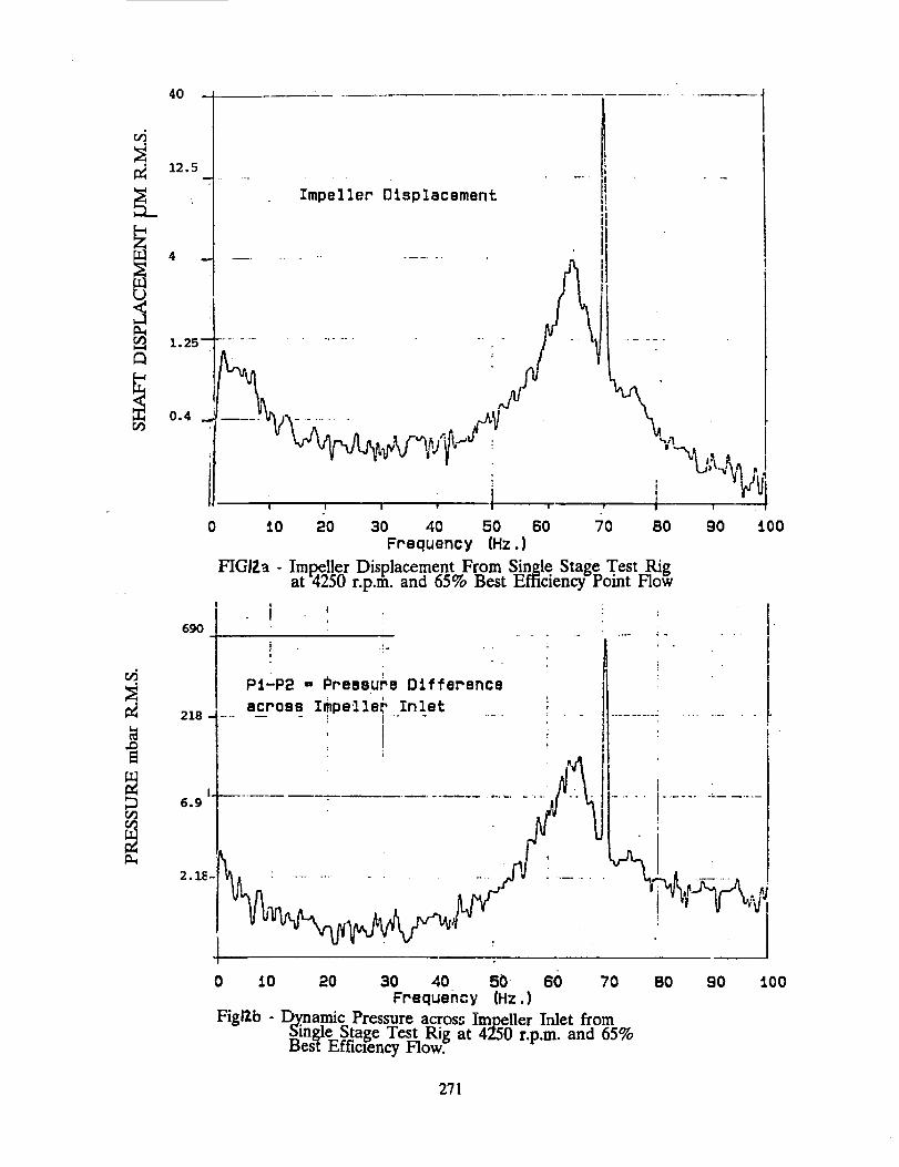
comprised a single impeller and diffuser stage mid was instrumentedwith shaft motion probesand dynamic pressuretransducersto examine distributions of pressurein the diffuser inlet,impeller shroud to easing gaps and near to thc impcller eye. Tcsts were carried out to
approximately 80% pump designspeed. Sum and difference measurements of two pressuresat -
180° at impeller eye showed a nonsynchronousfrequency componentwhich was out of phaseimplying a net resultant force on the impeller. This correlated extremely well with the resultantshaft motion as shown in fig.12a and fig.12b and was very similar to that obtained from the,
pump, fig. 10. Tests subsequently confirmed that this was an impeller inlet stall whichappeared to rotate relative to the impeller at a frequency equal to the difference of the
synchronous and subsynehronous frequencies. The forces involved were quite small and the
feedback element which was evidently present with the 7 stage pump was never repreduccd on
the test rig. In the final event no design changes were made to the pumps, although an impellerwith revised inlet geometry had been tested successfully in the single stage test rig. There were
however, significant improvements made to the build concentricity of the pump cartridge and a
change to the shaft material. Tests confirmed that subsynchronous vibrations were still presentbut a factor often below synchronous amplitude levels. No change in vibration was obtained
over a 48 hour endurance test at full load. The pumps have been in service for over twelveyears and have given trouble free operation.
During proving tests on the prototype of a new frame size of barrel casing pump in 1987, theopportunity was taken for an in-depth examination of the effects of annular clearance wear and
the influence of inlet swirl at the balance drum upon rotor dynamics and, in particular,subsynehronous vibration. The device used to control inlet swirl was similar to that described
in (7). The prototype was a six stage pump with radial diffusers and a balance drum with a
design maximum running speed of J000 rpm. The design parameters of this barrel easing
pump are set out in Appendix I. The materials chosen for the renewable wearing rings werechosen for their high wear resistance and freedom from galling. To maintain optimum
efficiency the recommended renewal clearances are set at 1.5 times the new design clearances.
It was decided to study the effects of wear up to a maximum of twice the renewable limits.
The tests were carried out in the production test facilities and the pump was installed on a
temporary, but substantial, support structure. The prime mover gave a variable speed
capability from 3600-5500 rpm, representing 10% above pump design speed. Instrumentation
was fitted to the pump to measure, head, flow, speed, loop temperature, bearing metal and oiltemperatures, axial thrust, balance return line flow. Dynamic measurements taken were
bearing housing vibration, (seismic), shaft to casing radial displacement and pressure
fluctuations in the suction, and discharge and balance return lines. The dynamic signals were
taped recorded for subsequent analysis off line. During each test discrete points were taken
over the performance envelope of the pump together with data from coutroll_ runs var).ing one
parameter at a time and keeping others constant, e.g. varying speed at constant dischargecontrol valve setting. The tests carried out are summarised in Table il and the incidenec of
subs)_chronous vibration during the tests is summarised in Table Ill. The pump was stable
when clearances were within the recommended limits, but became unstable with 2 x designclearances. In contrast inlet flow swirl control delayed unstable behaviour until clearances
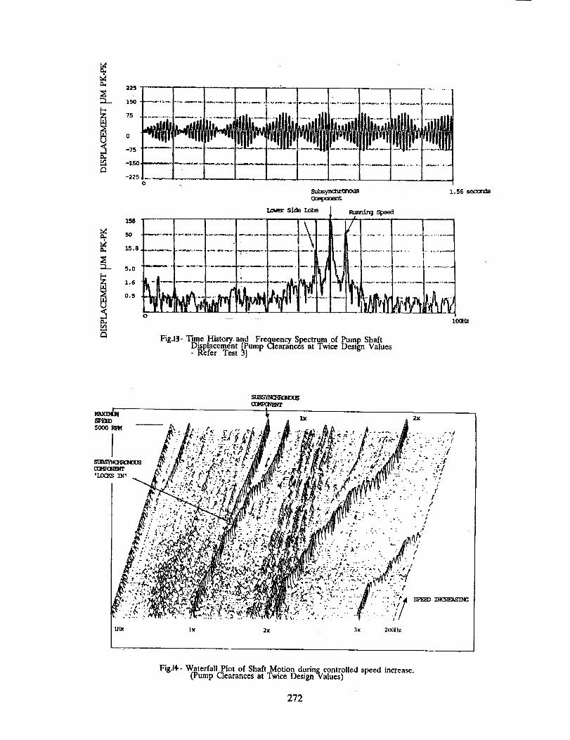
approached twice the renewable values. When the subsynehronous vibration occurred it had awell defined character. Figure 13 shows a time history and a spectrum of the shaft motion
taken during Test 3. The time history shows the typical beating resulting from the presence of
two strong vibration signals with frequencies close together. The spectrum shows not only therunning speed vibration and the subsynchronous vibration but also the sidebands associated
with these frequencies. This spectrum with its strong difference frequency, (running speed -
subsynehronous speed), and the similarly displaced sidebands is typical of this phenomenon.
253
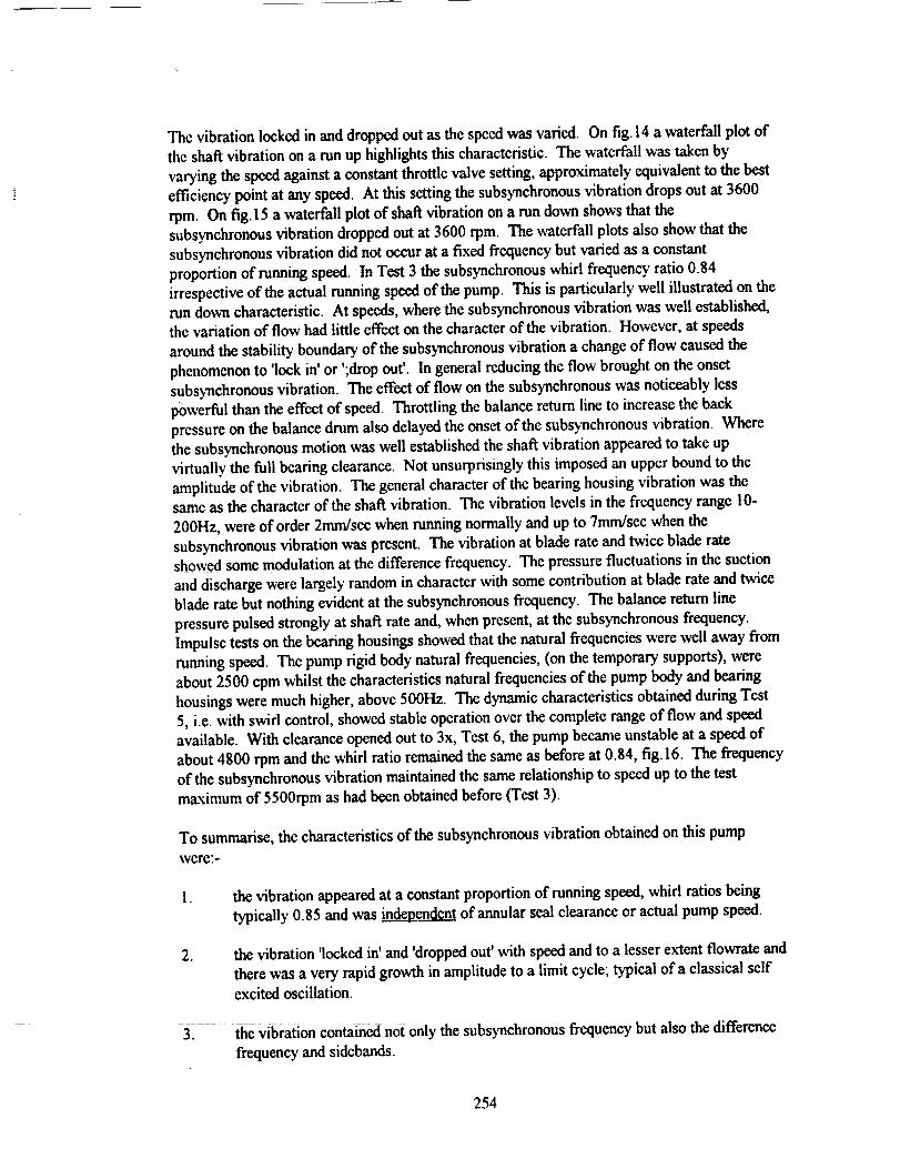
Thevibrationlocked in and dropped out as the speed was varied. On fig. 14 a waterfall plot of
the sha_ vibration on a run up highlights this characteristic. The waterfall was taken by
varying the speed against a constant throttle valve setting, approximately equivalent to the best
efficiency point at any speed. At this setting the subsynchronous vibration drops out at 3600
rpm. On fig. 15 a waterfall plot of shaft vibration on a run down shows that the
subsynchronous vibration dropped out at 3600 rpm. The waterfall plots also show that the
subsynchronous vibration did not occur at a fixed frequency but varied as a constant
proportion of running speed. In Test 3 the subsynchronous whirl frequency ratio 0.84
irrespective of the actual running speed of the pump. This is particularly well illustrated on therun down characteristic. At speeds, where the subsynchronous vibration was well established,the variation of flow had little effect on the character of the vibration. However, at speeds
around the stability boundary of the subsynchronous vibration a change of flow caused the
phenomenon to 'lock in' or ';drop out'. In general reducing the flow brought on the onset
subsynchronous vibration. The effect of flow on the subsynchronous was noticeably less
powerful than the effect of speed. Throttling the balance return line to increase the back
pressure on the balance drum also delayed the onset of the subsynchronous vibration. Where
the subsynchronous motion was well established the shaft vibration appeared to take upvirtually the full beating clearance. Not unsurprisingly this imposed an upper bound to the
amplitude of the vibration. The general character of the bearing housing vibration was thesame as the character of the shat_ vibration. The vibration levels in the frequency range 10-
200Hz, were of order 2mndsee when running normally and up to 7mm/sec when the
subsynchronous vibration was present. The vibration at blade rate and twice blade rateshowed some modulation at the difference frequency. The pressure fluctuations in the suction
and discharge were largely random in character with some contribution at blade rate and twice
blade rate but nothing evident at the subsynchronous frequency. The balance return line
pressure pulsed strongly at shaft rate and, when present, at the subsynchronous frequency.
Impulse tests on the beating housings showed that the natural frequencies were well away from
running speed. The pump rigid body natural frequencies, (on the temporary supports), were
about 2500 cpm whilst the characteristics natural frequencies of the pump body and bearing
housings were much higher, above 500Hz. The dynamic characteristics obtained during Test
5, i.e. with swirl control, showed stable operation over the complete range of flow and speed
available. With clearance opened out to 3x, Test 6, the pump became Unstable at a speed of
about 4800 rpm and the whirl ratio remained the same as before at 0.84, fig.16. The frequency
of the subsynchronous vibration maintained the same relationship to speed up to the test
maximum of 5500rpm as had been obtained before (Test 3).
To summarise, the characteristics of the subsynchronous vibration obtained on this pump
were:-
. the vibration appeared at a constant proportion of running speed, whirl ratios being
typically 0.85 and was independent of annular seal clearance or actual pump speed.
.the vibration 'locked in' and 'dropped out' with speed and to a lesser extent flowrate and
there was a very rapid growth in amplitude to a limit cycle; typical of a classical self
excited oscillation.
3_ the Vibration contained not only the subsynehronous frequency but also the difference
frequency and sidebands.
254
. the shaft vibration at the subsynchronous frequency indicated a forward processingwhirl, again typical of a self excited oscillation.
. thcrc was no evidence to prove that the subsynchronous vibration rcsponse was due to
a rotor natural frequency (i.e. not an unstable cigcnvaluc). .
. control of inlet swirl to the balance drum delayed the onset of subsynchronousvibration.
Since the mid 1980's there have been reported several more instances of the "near running
speed" nonsynchronous vibration problem, ref 7, 8, 9. In some cases major redesign of the
pump has been necessary to solve the problem. Opinions differ regarding the source of theproblem, some believe it is the excitation of the natural frequency of the rotor but others
believe that hydraulic destabilising forces in the impeller may be the source. Further research
and investigation will no doubt ultimately give more insight into such problems.
5.0 TRANSIENT VIBRATIONS
Transicnt vibrations - vibrations which result from rapidly changing operating conditions andwhich dccay with increasing time.
Transient vibrations in boiler feed pump installations are fairly rare although most modem
power stations have probably experienced pipework vibration resulting from either rapid
loading or unloading of the pump or from the rapid opening and closing of flow control valves.
Disturbed suction conditions can also lead to pipework vibration and vapour locking within the
pump causing the pump to eventually run dry. However, there are few documented examples
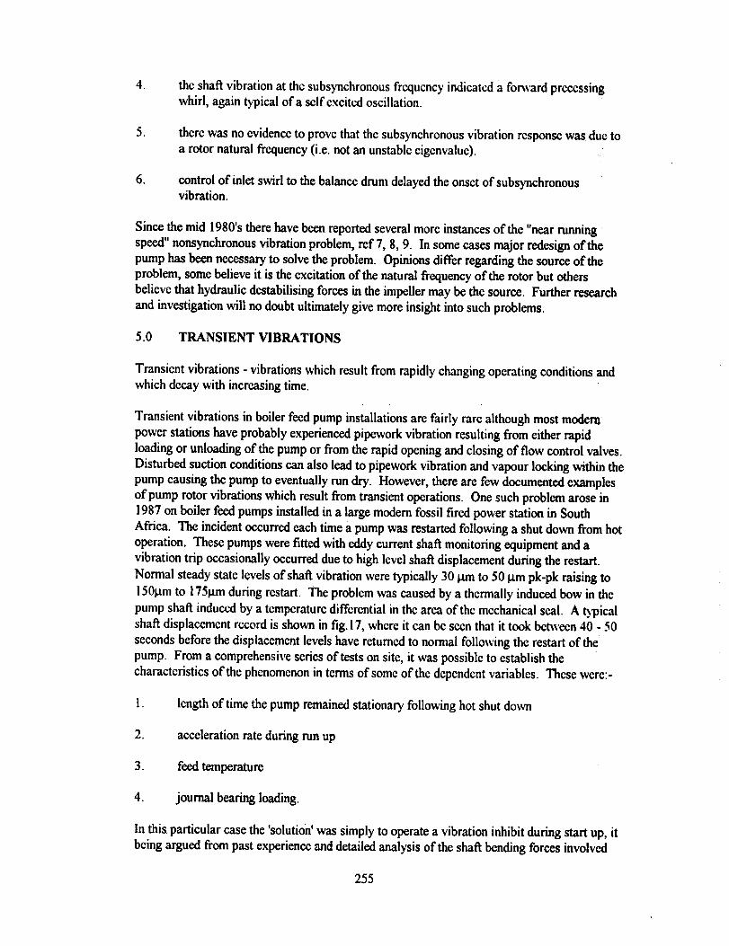
of pump rotor vibrations which result from transient operations. One such problem arose in
1987 on boiler feed pumps installed in a large modern fossil fired power station in South
Africa. The incident occurred each time a pump was restarted following a shut down from hot
operation. These pumps were fitted with eddy current shaft monitoring equipment and a
vibration trip occasionally occurred due to high level shat_ displacement during the restart.
Normal steady state levels of shaft vibration were typically 30 pm to 50 gm pk-pk raising to
1501,tm to 175Bin during restart. The problem was caused by a thermally induced bow in the
pump shaft induced by a tcmperaturc differential in the area of the mechanical seal. A _icaishaft displacement record is shown in fig. !7, where it can bc seen that it took between 40 - 50
seconds before the displacement levels have returned to normal following the restart of the
pump. From a comprehensive series of tests on site, it was possible to establish the
characteristics of the phenomenon in terms of some of the dependent variables. Thcse were:-
1. length of time the pump remained stationary following hot shut down
2. acceleration rate during run up
3. feed temperature
4. journal bearing loading.
In this particular case the 'solution' was simply to operate a vibration inhibit during start up, it
being argued from past experience and detailed analysis of the shaft bending forces involved
255
that the pump would not suffer accelerated wear. It is believed that this phenomenon occurs in
most boiler feed pumps fitted with mechanical seals. A review of Weir feed pump installations
carried out 1988 showed 127 fully operational pumps with over 1.6 million hours operation.
None of these were fitted with shaft displacement monitoring with alarm and trip function. In
the absence of shaft monitoring the phenomenon has gone unnoticed with, it would appear, no
adverse effect on long term integrity.
6.0 CAVITATION RELATED VIBRATIONS
Cavitation related phenomena are associated with the first stage impeller suction region and
may be responsible for many unusual dynamic phenomena in pump and piping systems, ref. 10.
The suction stage feed pumps designed by Weir Pumps in the 1970's for CEGB incorporated
inducers so that they could cope with the low NPSH transients associated with sudden loss of
load. One concern was the susceptibility of these designs to promote surging in the suction
pipework in the boiler feed system. Works test are generally unrepresentative of pipework
installations on site, particularly as the suction pipework often incorporates a throttle device to
control the suction pressure at inlet. This provides considerable damping to the suction
pipework, effectively inhibiting the propensity to surge. A series of special tests were carried
out in the Weir test facilities to examine the boundary of the surge phenomenon at various
flowrates and over a wide range of NPSH values. For these tests a free surface was introduced
between the throttle valve and the pump suction. A summary of the cavitation surge band is
shown in fig. 18. It was comforting to find that although a well defined surge envelope could bedefined it occurred at NPSH values below that available during loss of load transient.
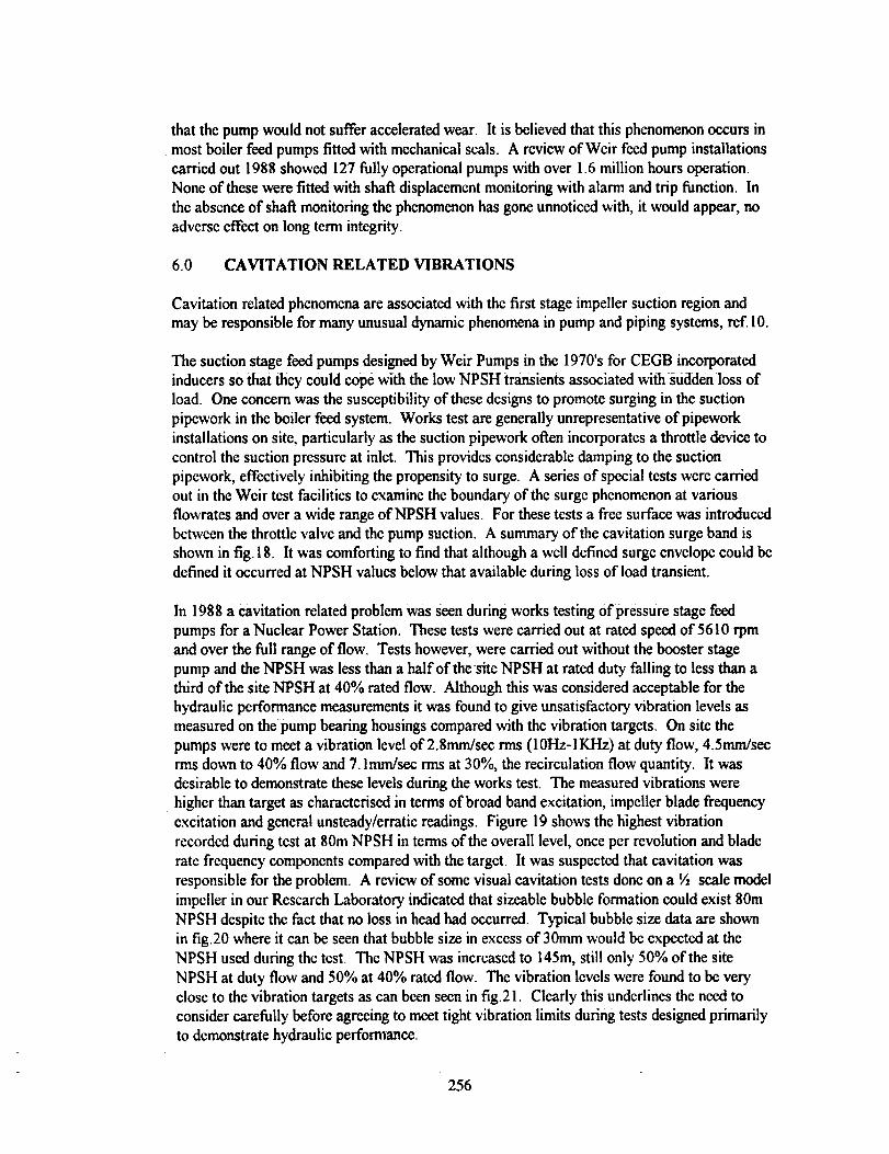
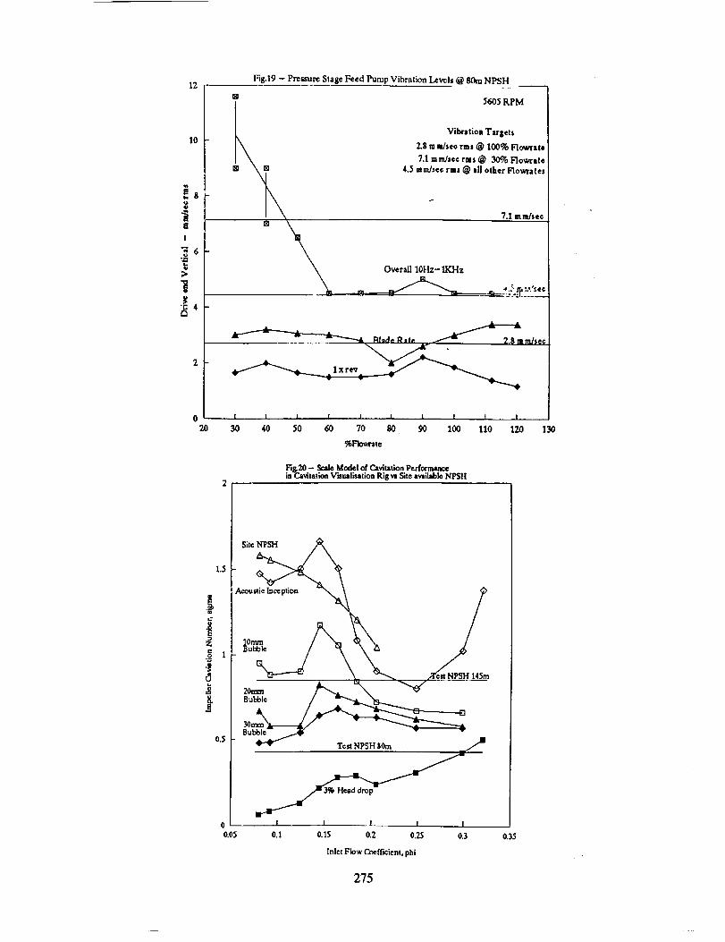
In 1988 a cavitation related problem was seen during works testing of pressure stage feed
pumps for a Nuclear Power Station. These tests were carried out at rated speed of 5610 rpm
and over the full range of flow. Tests however, were carried out without the booster stage
pump and the NPSH was less than a half of the site NPSH at rated duty falling to less than a
third of the site NPSH at 40% rated flow. Although this was considered acceptable for the
hydraulic performance measurements it was found to give unsatisfactory vibration levels as
measured on the pump bearing housings compared with the vibration targets. On site the
pumps were to meet a vibration level of 2.Smm/sec rms (10Hz-IKHz) at duty flow, 4.5mm/secrms down to 40% flow and 7. lmm/sec rms at 30%, the recirculation flow quantity. It was
desirable to demonstrate these levels during the works test. The measured vibrations were
higher than target as characterised in terms of broad band excitation, impeller blade frequency
excitation and general unsteady/erratic readings. Figure 19 shows the highest vibration
recorded during test at 80m NPSH in terms of the overall level, once per revolution and bladc
rate frequency components compared with the target. It was suspected that cavitation was
responsible for the problem. A review of some visual cavitation tests done on a ½ scale model
impeller in our Research Laboratory indicated that sizeable bubble formation could exist 80m
NPSH despite the fact that no loss in head had occurred. Typical bubble size data are shown
in fig20 where it can be seen that bubble size in excess of 30mm would be expected at the
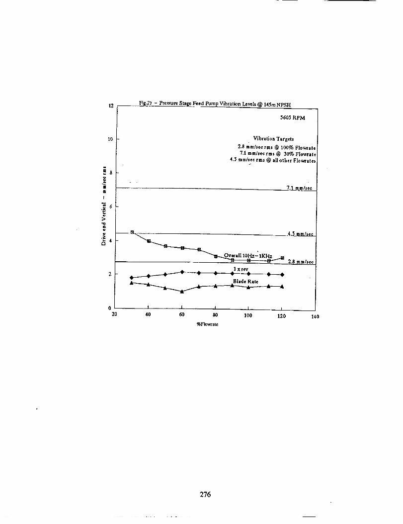
NPSH used during the test. The NPSH was increased to 145m, still only 50% of the site
NPSH at duty flow and 50% at 40% rated flow. The vibration levels were found to be very
close to the vibration targets as can been seen in fig.21. Clearly this underlines the need to
consider carefully before agreeing to meet tight vibration limits during tests designed primarily
to demonstrate hydraulic performance.
256

7.0 CONCLUDING REMARKS
The paper has provided examples of different types of vibration experienced in boiler feed
pumps for Power Station duties. It is likely that other manufacturers can cite similar problemsbut different solutions may have been adopted. The task of the methods of the pump designeris to try and eliminate the problems in any new designs and, preferably, before site installation.
This process is helped if manufacturers and users are encouraged to report on problem areas.
Clearly there are generic problem areas. The subsynchronous vibration problcm has generatedmore interest in the US than in Europe and there are many research projects directed toward
investigation of hydraulic destabilising forces and fine clearance seal dynamics. Cavitation and
NPSH related dynamic effects offer considerable scope for investigation relating to system and
pump rotor stability. Impeller blade frequency vibrations are not completely understood andfurther research into areas of concern would seem desirable.
257
8.0 REFERENCES
. UCHIDA, N. Radial Force on the Impeller of a Centrifugal Pump. Bulletin of theISME, Vol 14, No.76, 1971.
. HERGT, P., KREIGER, P. Radial Forces in Centrifugal Pumps with Guide Vanes.
Conference on Advanced Class Pumps. I.Mecb.E., 1970.
. BROWN, R.D., FRANCE, D. Vibration Response of Large boiler Feed Pumps.
Worthington European Technical Award 1974, Vol III, Hoepli, Milan, 1974.
. ZOTOV, B.N Selection of Number of Runner and Guide Mechanism Blades for
Centrifugal Pumps. Russian Engineering Journal, Vol LII, No. 11.
5. MAKAY, E., SZAMODY, O.1978.
Survey of Feed Pump Outages. EPRI Report - 754,
. FRANCE, D. Rotor Instability in Centrifugal Pumps. Shock and Vibration Digest,
Vol. 18, No.l, 1986.
7_ MASSEY, I. Subsynchronous Vibration Problems in High Speed Multi Stage Pumps.
Proc. 14th Turbomachinery Symposium, Texas A&M University, 1985.
. MARSCHER, W.D. Subsyncrhonous Vibration in Boiler Feed Pumps due to Stable
Response to Hydraulic Forces at Part Load. l.Mech.E Conference 'Part Load
Pumping, Operation, Control and Behaviour', 1988.
. FRANCE, D., TAYLOR, P.W. Near Running Speed Subsynchronous Vibration in
Centrifugal Pumps. Conference on Vibrations in Centrifugal Pumps, l.Mech.E.,
London, 1990.
10. NG, S.L. and BRENNEN, C. Experiments on the Dynamic Behaviour of Cavitating
Pumps. ASME Fluids Engineering, 1978.
11. BLACK, H.F. Lateral Stability and Vibrations of High Speed Centrifugal Pump
Rotors. Symposium on the Dynamic of Rotors, Lyngby, Denmark
258
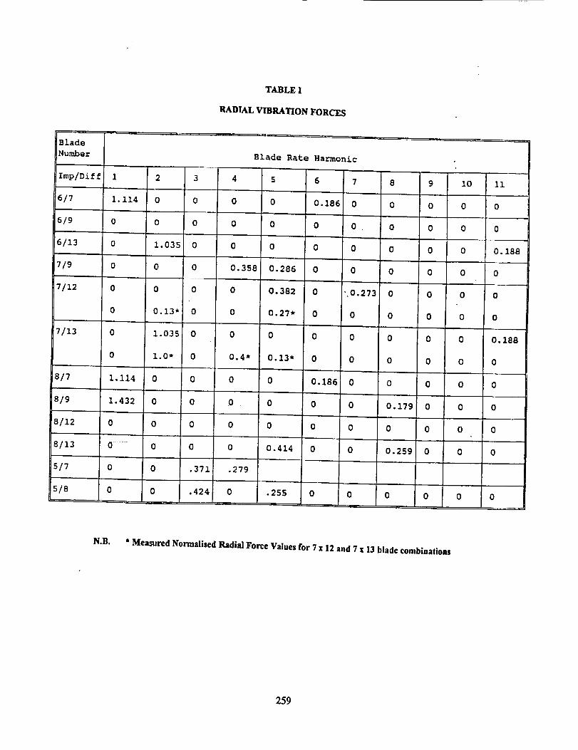
TABLE I
RADIAL VIBRATION FORCES
Blade
Number
!Imp/Diff 1 2 3 4 5 6 7 8 9
6/7 1.114 0 0 0 0 0.186 0 0 0
6/9 0 0 0 0 0 0 0 0 0
6/13 0 1.035 0 0 0 0 0 0 0
7/9 0 0 0 0.358 0.286 0 0 0 0
7/12 0 0 0 0 0.382 0 ",0.273 0 0
0 0.13" 0 0 0.27* 0 0 0 0
7/13 0 1.035 0 0 0 0 0 0 0
0 1.0" 0 0.4* 0.13" 0 0 0 0
8/7 1.114 0 0 0 0 0.186 0 0 0
8/9 1.432 0 0 0 0 0 0 0.179 0
8/12 0 0 0 0 0 0 0 0 0
8/13 0 0 0 0 0.414 0 0 0.259 0
5/7 0 0 .371 .279
5/8 0 0 .424 0 ,255 0 0 0 0
Blade Rate Harmonic
10
0
0
0
0
0
0
0
0
0
0
0
0
0
11
0
0
0. 188
0
0
0
0.188
0
0
0
0
0
0
N.B. * Measured Normalised Radial Force Values for 7 • 12 and 7 • 13 blade combinations
259
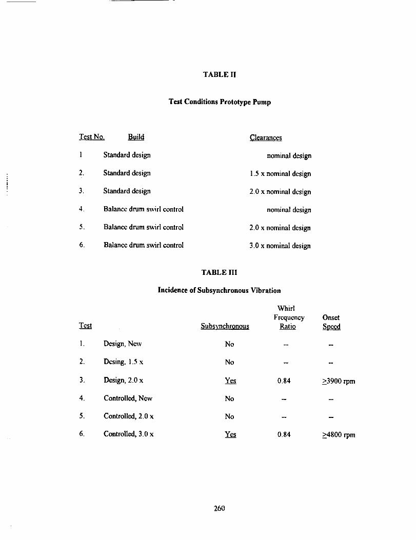
TABLE II
Test Conditions Prototype Pump
Test No. Build
1 Standard design
2. Standard design
3. Standard design
4. Balance drum swirl control
5. Balance drum swirl control
6. Balance drum swirl control
Clearances
nominal design
1.5 x nominal design
2,0 x nommal design
nominal design
2.0 x nominal design
3.0 x nominal destgn
Test
i. Design, New
2. Dosing, i.5 x
3. Design, 2.0 x
4. Controlled, New
5. Controlled, 2.0 x
6. Controlled, 3.0 x
TABLE III
Incidence of Subsynchronous Vibration
Subsynchronous
No
No
Ye.__.__s
No
No
Ye....__s
Whirl
FrequencyRatio
0.84
0.84
Onset
_>3900 rpm
m
>4800 rpm
260
160
140
Fig.1. Shaft Speed Hydraulic Unbalanceasa Functtonof Flow (After Uchida)
Speed 1750 rpmImp MaMapprox 15KgMax Force approx 60 x,_"
= 85N
E¢cof Mass= 16Slum
0.30
40
2O0.5
Relative Flow Rate Q/Opt
1.5
Fig.2 - Pump Shaft Displacement as a Function of Flew
Design Flow 100%
Recirculation Flow 10%
75 ym
250 _m
261
-20 __Fig.3a Dynamic Force - Influence of B[ade Number and Gap G
,,-30
(2.,.
_-40u
¢g
i
r,.
B
-700
• n ty velocitypherat
D - Impeller diameter
b - Impeller Outlet Width
I I I
50 100 150 200
5x'q,O =9% ...0_7x5,G =20%_.d¢.7xi,0-=20% -B--7x3,0=20%
%Duty Flow
InfluenceofImpeller/DiffuserGap G
- densityV peripheral velocity
D - Impeller diamcter
b - Impeller Outlet WidthI 1
50 I00 150 200
7xl,O = 50% .__ 7xI,G =20% --dk-7x3,G = 20% --E3-7x3,G = 10%
% Duty Flow
262
15 Fil_.4 Blade Rate Vibration
10
.J
e i i i i i i
0 20 _ 60 8O 1_ 120 140
Daty Flaw
I........... ]
/ i \JJ!
(.,,2_
- - I
# t
FIG.5 ARRANGEMENT OF MAIN FEED.PUMPAND SUPPORTING STEELWORK
/
_J\
iI |
263
FI66_ON LOAD VIBRATION OF PUMP COMPARED WITH VIBRATION OF PUMP
EXCITED BY AIR DRIVEN ROTARY OUT OF BALANCE DEVICE
v"toGJ
CL
(JOJu)
EE
--Jl_J>
J
ZO
rrCO
L_Z
C3Z
(,9Z
L_CO
25.
24.
23.
0
3000.
KEY
+ O.E. HORIZONTAL- ON LOAD
v D.E. HORIZ- EXCITF.D(gCALEW4)0 N.D.E. HORIZONTAL- ON LOADo N.D,E. HORIZ - EXCITED[$CALEw4) --'
--?
-1
T.
,-i
,7
3400. 3800_ 4200. 4600. 5000. 5400. 5BOO. 6200. 6600.
PU_IP SPEED rD[n.
264
FIGSb RESPONSE OF PUMP ON STEELNORK COMPARED NITH PUMP
ON CONCRETE FLOOR - EXCITED BY ROTARY DEVICE
vroILlQ.
(JQ,)U}
EE
.JLU>LU.J
Z(:3I-4I--
ITrni-i:>
{.9Z
0I
(.9Z
fl-
LUm
6.
""'l'"'l'""]'"'l'"']"np,,,I,,,,I,,,,i,,,,i,.q,,, q,,,,i,,,,i,,,,I,n,l,,,KEY
Z N.D.E, HORZZ -EXCZTEO ON FLOOR
v D.E. HORZZ - EXCZTED ON STEELWORK
: @ D.E. HORZZ -EXCITEO ON FLOOR
[] N.D.[. HORTZ - EJ(C];TF..O ON STEELNORK
265
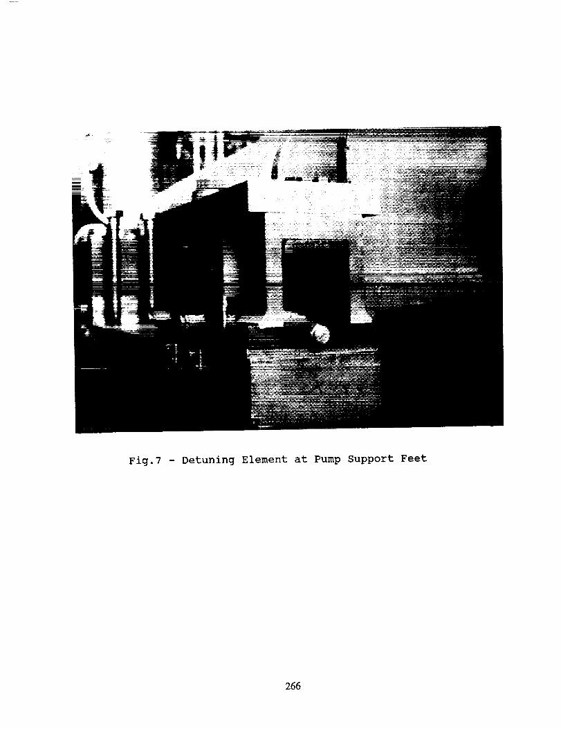
Fig.7 - Detuning Element at Pump Support Feet
266
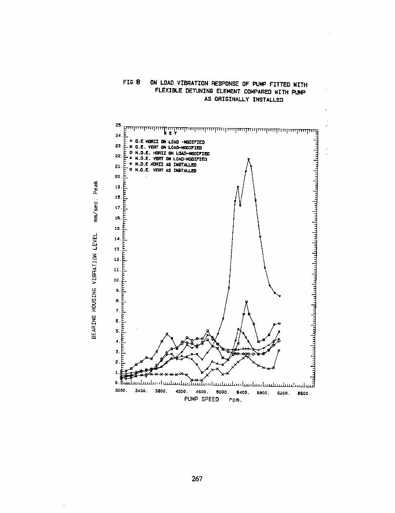
FIG ON LOAD VIBRATION RESPONSE OF PUNP FITTED HITH
FLEXIBLE DETUNINS ELEMENT CONPARED NITH PUNP
AS ORIGINALLY INSTALLED
v[oIZ.1
D...
UOJIn
¢:::E
.--IU.I:>LLI._J
ZO
i1.
tT
Ill
{.9ZH
0"r
COZHE.<_L_Jm
25
__'"J'"'_....'....k"t'_'""....,'"'J'"'J'"'l'"','"'i'"',,',,,,,,,l,,,,i,,,,l-,,,....
J
O.
3000. 34oo. 3ooo. 42oo. 4600. 5ooo. 54oo. .800. s2oo. eeoo.PUMP SPEED rom.
267
|
,_ 5-t:L
_3r
_2->-
rL-1 -
/ <=..I'o-o=.._l"tJ
sttA_-r sl_D
I
1 2 3 _ 5 6
SHAFT SPEED (cpm ,, 10-31
SUBSYNCHRONOUS
\SHAFT OISPLA_SNT SP_M
ii
0 ° .
20 _0 60 BO 100
FR_. H_
Fig.9. Whirl Frequency Ratio andFrequency SpectrumFr0in 4 Sfage Boiler Feed Pump
i
268
3i.6
FI9.1o - Frequency Spectrum taken at Drive End Bearing for 7 Stage
Pump with 2 x Design Clearances at 5850 r.p.m._7-SHz)
4 Hm.BO Hz.
i •
LI
20O
FREQUEHCY (Hz.)
269

iO0.F---.: ......... T....... T..... X....... T.....Z...... 3"...... I....... T......... i ......... F _ .... I .... -' ..... [ ....._- , ! I : I : ! I ; ! i IX! i "
L
.,- i ! i 1 .: i.. ! .!x/_ " ," i _ i Iwv. _-.--------T-- _-+-_- _*- ............ _ ...... '-_-_)* _--"-'-'-X "_'- ""-t ....... _ .... _ ............. " .... "
i , I , _ [ _ _* t _ , , '
40._ _.'....,_. L __ ......._........4...... J .... _....... - ..... !..._ ........ )........_J
_ L_.... r x.._-;--x -_'I r/i -"! .... e---o---.(_....... ! , i i
: :_-. _ I .1
U ...... _ -_ ; - - : .............. 1-- . ; ....... _ ..... :........ _.... i .... ; ..... - ._
' : ' ! | _ ! o_sl.n Sp.d i i i: i ! i i 5850 r.p.m. .
' i i i i• ii50. _ .................... , ...... i....................... - ._
' _ ' ! " ' ' _ -X " '
tO0 x,----x- : _ ' i : "" ! i _ '• _- .......... .___._-- _ -- --x __-.-w-.; ..... _ ...................... ,
Z ol ; _ _ • . :, i
m O : ' ' ' ' ,- ' 'LU C. G-- ! ....
< _ - . : _. ..... (_.__..L o--: .... o--...... ,_ i _ " --r ,_ -50., ..................... , ...... ¢............. r-........r ...... _...... _ ..... .-_:,"-- -",_.................I"1. , _ • : - '?..)
1....... _ ............................ L................ ;.....-_00. , .... .-----._ .............. _ _ i ; : '. ; : -
.
-i5o :. : _ J _ 1 _J. _ , I _ . i
4000. 4400. 4800. 5:_00 . 5600. 6000. 6400 . 6800.
PUMP SPEED (R.P.M.)
o NZ3::0""re"t'l--
7LIJ>--7
I P-J
0{3ZfJ
FIe. lta.- Amplitude and Phase for Design and Twice
Design Clearancea for a 7 SLags Pump
_.to.... ,. , ..... .t ......i...... !.... ' "l .......] " 1.... I j._T .... ! -
ioo.= ............... J.........i.... i............... ; ....... L ................._ ..... ,_____ .... _................ 4........; Synchronous :, - i ; } _i ,
go... Llne:..._. :........ -.-_ ...._.._ ....... J:_-i .... :-.--
8o._........... .............. .... -- .......,.....
"I _ ../'_rr _ "-_ l :, i i "I X--- tin._ i 1 ; !. : ; u.=.uea o.60.,_-, ._'____..__._T........-_-,-__ ! ...... _ 0 N.O.E.Bear_ng.
• t ! _ ,_ _ Balance Drum.5o.L i ......, ..L ,....... l.......I.......J.... I, .J. ,......................
4000. 4400. 4800. 5200. 5600. 6000. 5400. 6800.
PUMP SPEED (R.P.M.)
FIG.lib.- Frequency of Non-synchronous Vibration
versus Pump Speed fop a 7 Stage Pump
270
v5
=.
L
C_
r/3
Dr/3
40
12.5
4
1.25
0.4
690
Impeller Displacement
fl, , , i i • , , ',%0 :tO 20 30 40 50 60 70 80 90 ,00
Frequency (Hz.)
FIGIZa - ImReller DisplacementFrom Sinzle Stage TestRigat 4250 r.p.m, and 05_/o tlest Efficiency Point blow
i• _ . ..
.'.- . . ;!
P:t-P2 = Pressure Difference
across Impelleb Inlet218 ...... _ ......
0 i0 20 30 40 50 60 70Frequency (Hz.)
Figitb - Dynamic Pressure across Impeller Inlet fromSinzle Stage Test Rig at 4250 r.p.m, and 65%Bes_ Efficiency Flow.
80 90 100
271
225
150
75
0
-'/5
-15C
-225
158
5O
15.8
5,0
1.6
0.5
-: .....I.......L,_.
0
::d--.......
0
.........,.,_.....!.......1.....
_ slc_I_obe
i, !
I
(
/
-! , i .........., !
i
.56 _
10_
Fig.B- TLme History. and FreRuency Spectrum of Pump Shaftu_pmcemen Lrump ulearances at Twie_ uesign Values-1_eier les Jj
5000
I
UIz
Fig.14- Waterfall Plot of Shaft Motion durinRcontrolled speed increase.(Pump Clearances at Twice Design "Values)
272
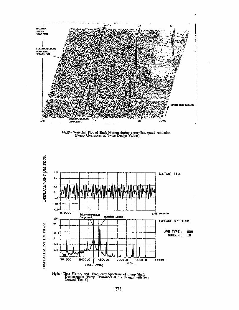
Fig.L_- Waterfall Plot of Shaft Motion dudn_eontroiled speed reduction.(Pump Clearances at Twice Design "Values)
..J
i 84 N42
-42 ....
-84
-126
....I ......
! r I_I Li I i .... i_
i
30.000 2400.0
I !1.6
0.5
0.0000
_.g speed
i
F _
t"--m4800 . 0 7200 . 0
-- INSTANT TIME
N
420Gllz (70H=}
' II
_J ,
I| J
[! ! L
9110O. 0 ! i_.
CPN
AVERA6E SPECTRUM
AVB TYPE : SUMNUMBER: 16
FigJ&- Time History and Frequency Spectrum of Pump ShaftDisplacement [Pump Clearances at 3 x Design, with Swirlt..ontrol lest oJ
273
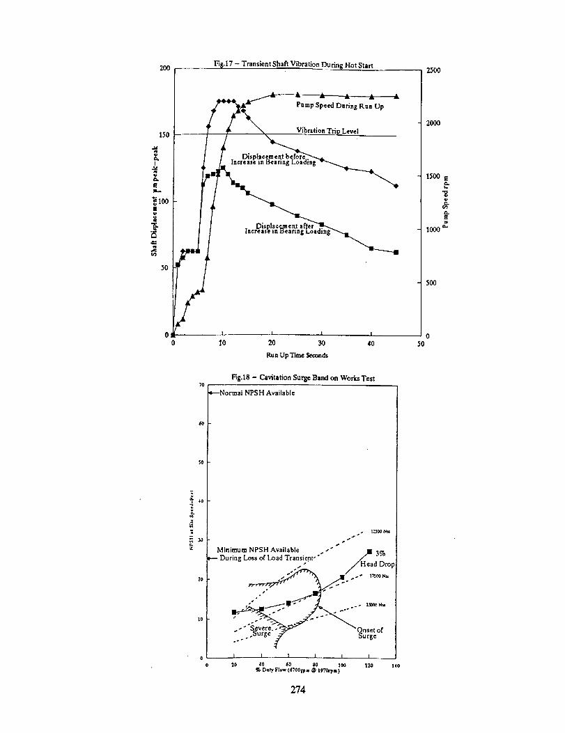
200 FIB,17 - Transient Shaft Vibration During Hot Start 25OO
00
Pump Speed Daring Run Up
Vibration TriELevel
I
I0I I I
20 30 40
Run Up Time Seconds
Fig.18 - Cavitation Surge Band on Works Test
SO
¢)
- 3O.,n
ZO
0
0
*---Normal NPSH Available
p
.+.---+-----1 I I I I I
")0 40 60 $0 100 120 140
% Oat_' Flow (6'700El_m @ lg?0rpm)
274
2OOO
1500 t
i.
[
looog
5OO
050
12
I0
020
E
I
>
i
Fig.19 - Pressure SIage Feed Pump Vibration I..cvcls @ 80m NPSH
[] 5605 RPM
VibrztioaTargets
2,$ m m/see, rms @ 100% Flowrate
7.1 mmhe¢ rms @ 30% FlowrateI_ a 4.5 mm/se© rm @ all other Flowtates
7.1 m m/see
Owrall 10Hz- 1KHz
--_---_=-_r. ....
3O 40 50 60 7O 80 9O
%_te
.L J 1
100 110 120 130
Fi&20 - Scale Model of Cavitation Pedocmancein Cavitation Visualisation Rig va Site available NPSH
1.5
Z
g 1
0.5
0.35
0 I I I I I
0.05 0.1 0.15 0.2 0.25 0.3
Inlet Flow Coefficient, phi
275
12
10
020
g
BGJ
_6"£
Fig.2_ - Pressure Stage Feed Pump Vibration Levels @ 145m NPSH
56O5 RPM
Vibration Targets
2.8 ram/see rms @ i00% Flowrate7.1 mm/se¢ rms @ 30% F'lowrate
4,5 ram/see rms @ all other Flowrates
7.1 ram/see
-_ 2.8 mm/se¢.¢
1 X r¢v
BladeRate
I I t I I
40 60 gO 100 17.0
%Fiowrale
140
276