my biggest success in balancing a fan was a few years ago
TRANSCRIPT
BALANCING BY THE COMPONENTS METHOD
My biggest success in balancing a large fan was a few years ago, but what I learnt may be of
interest to people doing balancing today.
It was a constant speed 590 r/min boiler ID fan, double entry impeller, 11 ft diameter, 21.5
tons mass, 2370 h.p. (Love those old units - but it was in the pre-SI days here in Australia).
The impeller was too long to be treated as a single plane, but too short for two-plane treatment.
There are 16 of these fans, and a rotor and impeller are shown in a lathe:
U-bolt clamps mounted on the inlet flaring were used as trial masses. These were placed in
the same angular position on each end.
We used a velocity transducer to measure the vibration amplitude at each bearing. The
instrumentation read in displacement. Phase was measured with a stroboscope, tuned to the
value of maximum vibration.
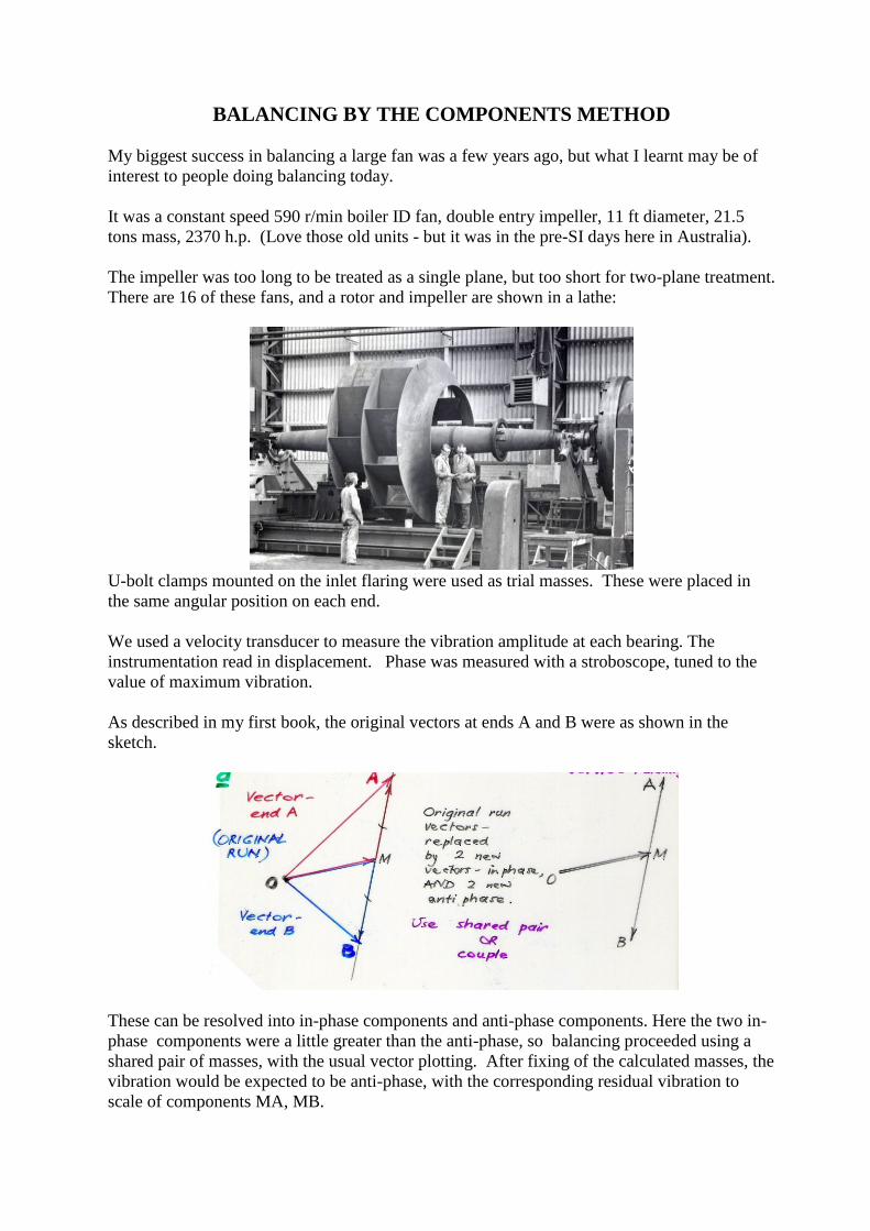
As described in my first book, the original vectors at ends A and B were as shown in the
sketch.
These can be resolved into in-phase components and anti-phase components. Here the two in-
phase components were a little greater than the anti-phase, so balancing proceeded using a
shared pair of masses, with the usual vector plotting. After fixing of the calculated masses, the
vibration would be expected to be anti-phase, with the corresponding residual vibration to
scale of components MA, MB.

If this level was not acceptable, the process could be repeated, but with masses in anti-phase
configuration.
If the original vectors were much larger in anti-phase than in-phase, then the pair of masses
would be placed on the impeller, one on each end as before, but 180degrees apart in phase to
give a couple effect: the right hand situation in this sketch:
This method is essentially the same as balancing a flexible rotor with a limited choice of
balancing planes. The vibration at around the first critical speed would be mostly in-phase,
and near the second critical speed, mostly anti-phase.
The end result for a rigid rotor could be achieved also by a two-plane balance, the “Thearle”
method, as used in today’s portable equipments. However, this needs an extra run to speed,
and it may be more economic to use the components method, and return for the second stage if
necessary.
Welding was not allowed on this alloy steel impeller, so holes had to be drilled to bolt on the
balance masses. The first hole took over an hour – what a hard steel we thought. The fitter got
a new drill – and it took only 5 minutes for the second hole!