1040property.vailwilliams.com/property_images/544/brochure_-_1040... · four pipe fan coil...
TRANSCRIPT

Exceptional. Every day.
_1040Pre-let Opportunity
105,056 sq ft
OFFICE

A BUSINESS LOCATION WHERE EVERY DAY THINGS BECOMEEXCEPTIONAL AND EXCEPTIONAL THINGS HAPPEN EVERY DAY.
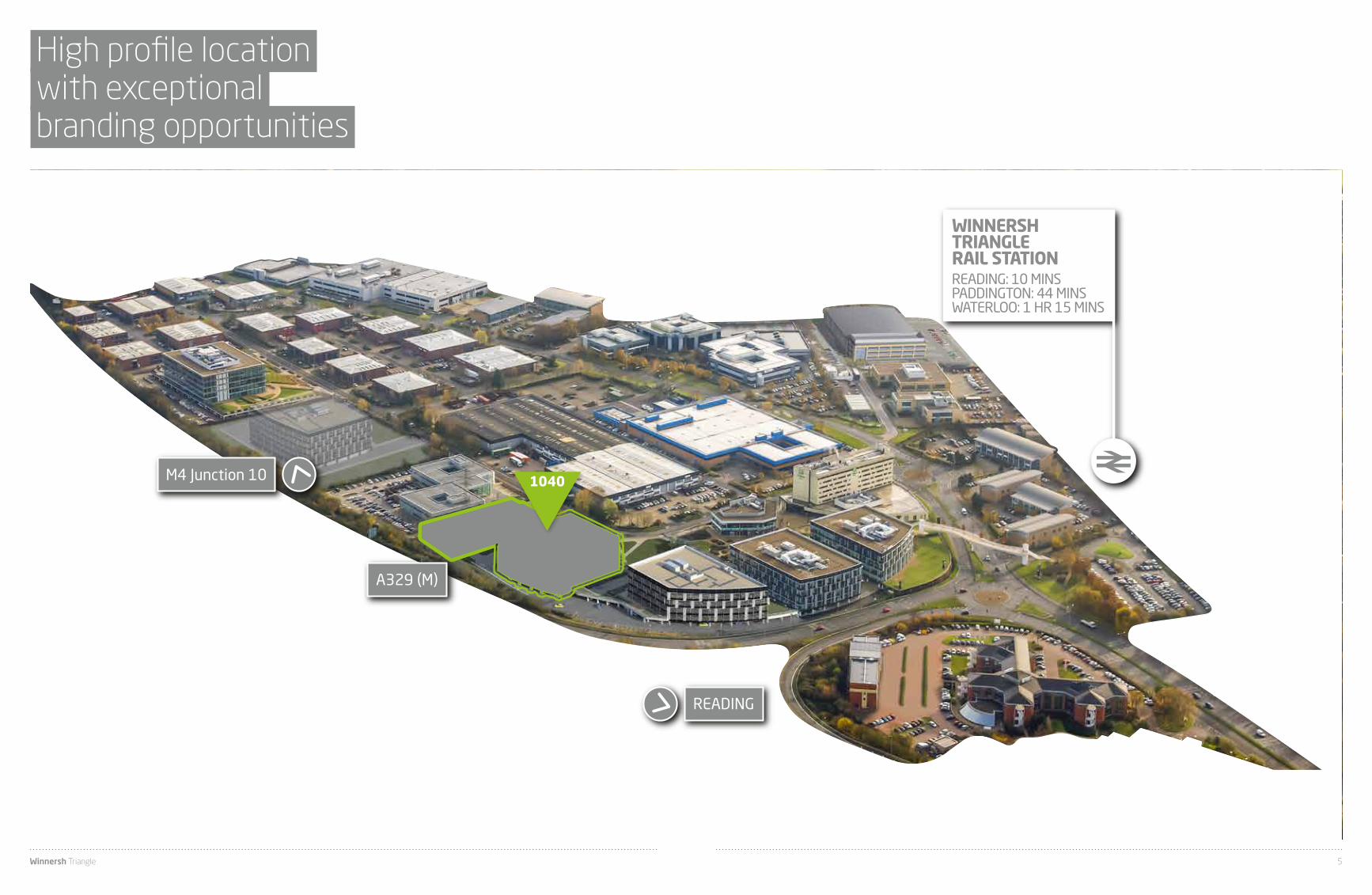
WINNERSH TRIANGLERAIL STATIONREADING: 10 MINSPADDINGTON: 44 MINSWATERLOO: 1 HR 15 MINS
M4 Junction 10
READING
A329 (M)
1040
High profile location with exceptional branding opportunities
Winnersh Triangle 5

1040available
for pre-let
Available for pre-let, building 1040 will provide 105,056 sq ft of Grade A office space over ground and four upper storeys.
Winnersh Triangle 7

Clear open floor platesflooded with light
SPECIFICATION Clear floor to ceiling height of 2.9m
Fully accessible raised access floors with a minimum clear void of 120mm together with accessible suspended ceiling
3 passenger lifts
Structural grid based on 9.0m x 9.0m with a 1.5m planning module
Double height reception area
PIR controlled recessed LED lighting designed in accordance with LG7
Four pipe fan coil air-conditioning
Showers and changing facilities
Male, female and accessible WCs
Secure parking in a ratio of 1:266 sq ft
36 secure cycle storage stands
EPC rating ‘B’ targeted
Target BREEAM Rating of ‘Very Good’
Indicative floor plate
Winnersh Triangle 9

Floor plans
GROUND AND FIRST FLOOR SECOND TO FOURTH FLOOR
LEVEL SQ FT SQ M
FOURTH FLOOR 21,581 2,005
THIRD FLOOR 21,581 2,005
SECOND FLOOR 21,581 2,005
FIRST FLOOR 19,482 1,810
GROUND (PODIUM) FLOOR
RECEPTION
19,482
1,345
1,810
125
TOTAL 105,056 9,760
*Plans not to scale. Indicative Only.
PARKING SPACES 395 (1:30 spaces per SQ M / 1:266 spaces per SQ FT)
Reception
Winnersh Triangle 11

UNIVERSITYOF READING
B3
03
0
B
30
30
A3
21
A3
21
A3
21
A3
21
A3
21
A3
21
A3
21
A3
21
B3034 B3034
A4
London Road
A4
London Road
A4
A4
A4
A327 A32
7 A3
27
Basingstoke R
oad
A329
A329 Wokingham Road A329 Reading Road A329
A
329
A329
London Road
B3270
B
327
0
A3
27
A3
27
M4
A329 (M)
10
11
M4
M4
A329 (M)
R I VE R T
H
A ME S
BEARWOOD LAKE
REDGRAVEPINSENT
ROWING LAKE
EARLEY
READINGWEST
READING
WINNERSH
WINNERSHTRIANGLE
WOKINGHAM
WinnershMeadows
DintonPastures
KeephatchNature
Reserve
BEARWOOD LAKES GOLF CLUB
BILLINGBEAR PARK GOLF CLUB
Winnersh Triangle is well placed to take advantage of the Thames Valley’s excellent motorway network.
The Park has its own slip road onto the A329 (M), which provides direct access to the M4 motorway in less than five minutes and the M25 London orbital motorway is a 20 minute drive.
Central London (38.7 miles), Oxford (31 miles) and Heathrow (23 miles) are less than an hour away and the M3 motorway (12 miles) gives fast access to Southampton and the Business Jet Hub at Farnborough Airport.
Closer to home, Reading town centre is less than 10 minutes drive (or, for those who prefer to take the bus, Reading’s Park & Ride scheme operates from just outside the Park).
Exceptional connectivity
BY ROAD
Source: AA Route Finder
0 miles
0 miles
40 miles
40 miles
60 miles
60 miles
70 miles
70 miles
20 miles
20 miles
M4 (J10)
Reading
M25 (J15)
Heathrow (T1, 2 & 3)
Central London
Gatwick
2.2 miles
5.6 miles
20.4 miles
23 miles
38.7 miles
62.4 miles
KEY
Petrol Station
Pub
Cinema
Golf Club
Spa
Goals
Pharmacy
Green Space
Hotel
Park & Ride
Cycle Lane
Post Office
Supermarket
Restaurant
Dry Cleaners
Food Store
Food Store
Gym / Leisure
M4
A4
A4
M4
A322
A308
A40
A33
A329
A404
A329 (M)
M4
M1
A3
M3
M3
M25
M25
M40
8/9
10
111
1
1a 1
4b
2
10
4
3
1
WOKINGHAM
WOKING
WINDSOR
FARNBOROUGH
READING
MAIDENHEADSLOUGH
BRACKNELL
CENTRALLONDON
GATWICK
HEATHROW
Winnersh Triangle 13
00
60
3090JOURNEY
TIMES
1hr 15mins
WATERLOO
44mins
PADDINGTON
mins
mins
mins
00
30
1545TRAINTIMES
19
49WATERLOO
WATERLOO
02PADDINGTON
32(change at Reading)
(change at Reading)
mins past 02
READING
mins past
mins past
mins past
mins past
10mins
JOURNEYTIMES
00
60
3090mins
mins
mins
32mins past
TRAINTIMES
TRAINTIMES
02mins past
mins past
HEATHROW
32
GATWICK
mins past
00
60
30JOURNEY
TIMES1hr 31mins
GATWICK
mins
mins
1hr 30mins
1hr 18mins
HEATHROW T1, 2 & 3
(multiple changes)
(multiplechanges)
(multiple changes)
HEATHROW
19
49
GATWICK
mins past
00
30
1545
00
30
1545
PADDINGTON
19
49WOKINGHAM
WOKINGHAM
mins past
mins past
READING06mins
WOKINGHAM
READING
1hr 24mins
HEATHROW T5
HEATHROW T4
LONDON STATIONS AIRPORTSNEARBY TOWNSOUR OWNRAIL STATION
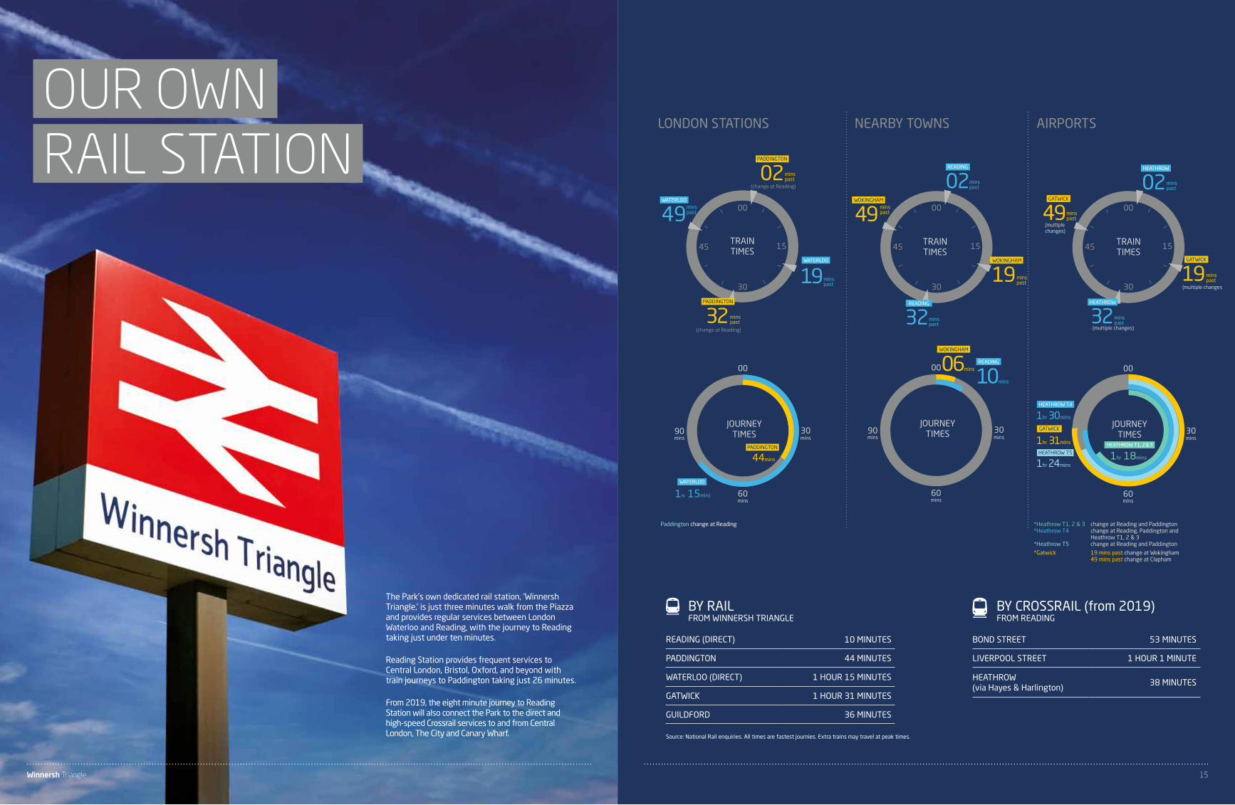
The Park’s own dedicated rail station, ‘Winnersh Triangle,’ is just three minutes walk from the Piazza and provides regular services between London Waterloo and Reading, with the journey to Reading taking just under ten minutes.
Reading Station provides frequent services to Central London, Bristol, Oxford, and beyond with train journeys to Paddington taking just 26 minutes.
From 2019, the eight minute journey to Reading Station will also connect the Park to the direct and high-speed Crossrail services to and from Central London, The City and Canary Wharf.
Paddington change at Reading *Heathrow T1, 2 & 3 change at Reading and Paddington*Heathrow T4 change at Reading, Paddington and Heathrow T1, 2 & 3*Heathrow T5 change at Reading and Paddington
*Gatwick 19 mins past change at Wokingham 49 mins past change at Clapham
BY CROSSRAIL (from 2019)FROM READING
BY RAILFROM WINNERSH TRIANGLE
BOND STREET 53 MINUTES
LIVERPOOL STREET 1 HOUR 1 MINUTE
HEATHROW (via Hayes & Harlington)
38 MINUTES
READING (DIRECT) 10 MINUTES
PADDINGTON 44 MINUTES
WATERLOO (DIRECT) 1 HOUR 15 MINUTES
GATWICK 1 HOUR 31 MINUTES
GUILDFORD 36 MINUTES
Source: National Rail enquiries. All times are fastest journies. Extra trains may travel at peak times.
Winnersh Triangle 15
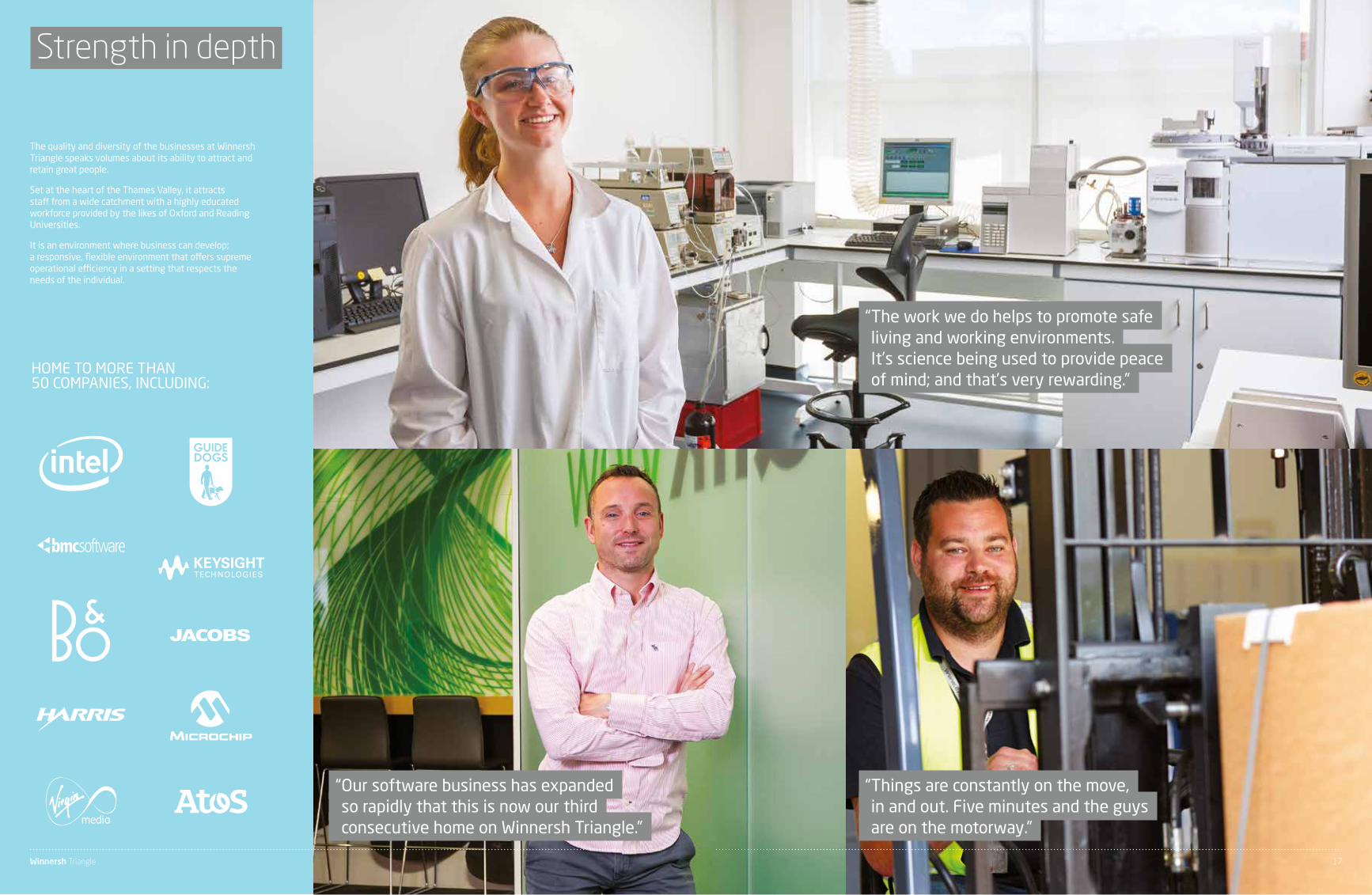
Strength in depth
“ Our software business has expanded so rapidly that this is now our third consecutive home on Winnersh Triangle.”
“ Things are constantly on the move, in and out. Five minutes and the guys are on the motorway.”
The quality and diversity of the businesses at Winnersh Triangle speaks volumes about its ability to attract and retain great people.
Set at the heart of the Thames Valley, it attracts staff from a wide catchment with a highly educated workforce provided by the likes of Oxford and Reading Universities.
It is an environment where business can develop; a responsive, flexible environment that offers supreme operational efficiency in a setting that respects the needs of the individual.
HOME TO MORE THAN 50 COMPANIES, INCLUDING:
“ The work we do helps to promote safe living and working environments. It’s science being used to provide peace of mind; and that’s very rewarding.”
Winnersh Triangle 17
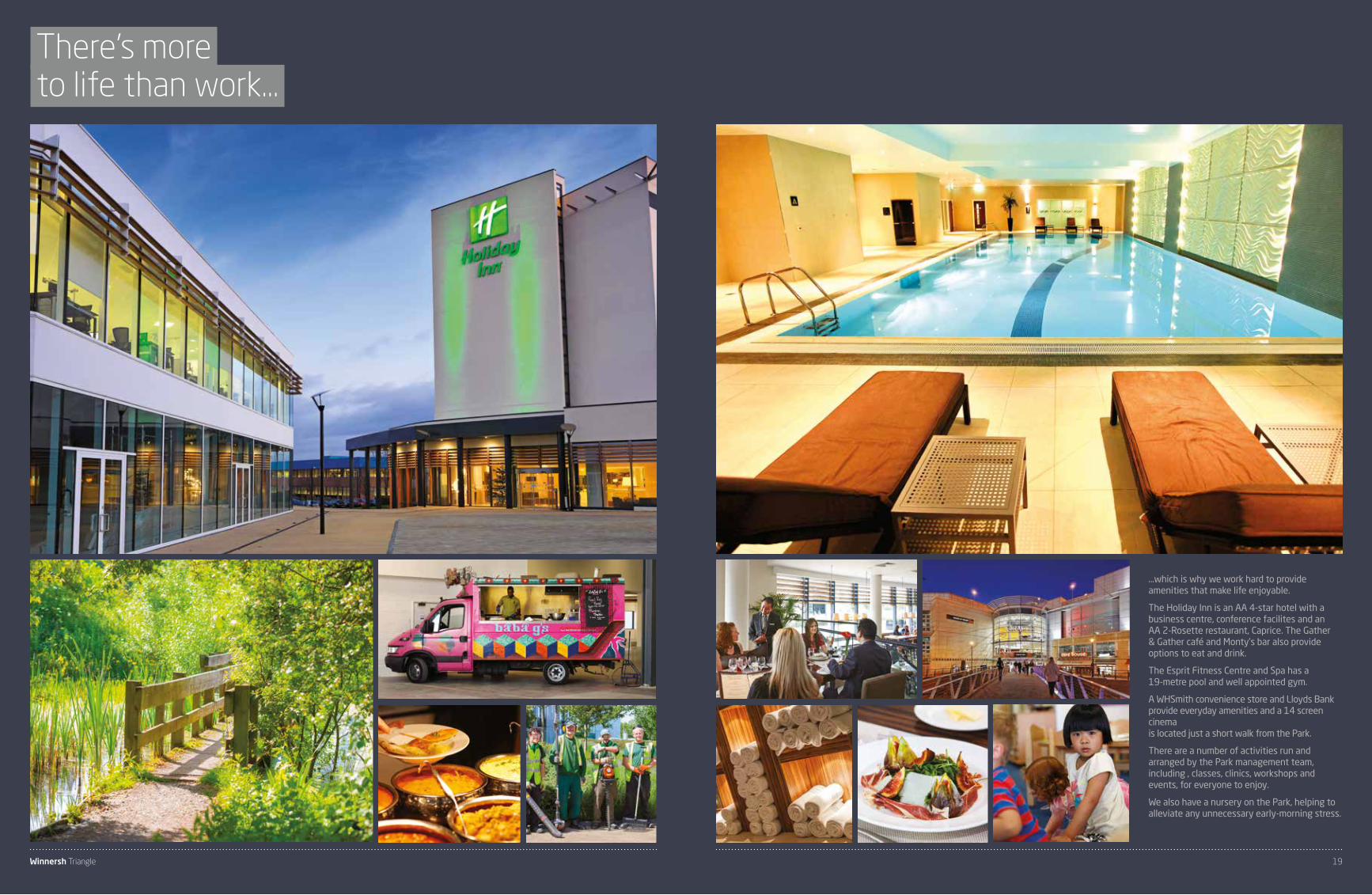
…which is why we work hard to provide amenities that make life enjoyable.
The Holiday Inn is an AA 4-star hotel with a business centre, conference facilites and an AA 2-Rosette restaurant, Caprice. The Gather & Gather café and Monty’s bar also provide options to eat and drink.
The Esprit Fitness Centre and Spa has a 19-metre pool and well appointed gym.
A WHSmith convenience store and Lloyds Bank provide everyday amenities and a 14 screen cinema is located just a short walk from the Park.
There are a number of activities run and arranged by the Park management team, including , classes, clinics, workshops and events, for everyone to enjoy.
We also have a nursery on the Park, helping to alleviate any unnecessary early-morning stress.
There’s more to life than work…
Winnersh Triangle 19

Specification
1.00 GENERAL DESCRIPTION
The works comprises a five storey office building, with 2 storey atrium, constructed on a single storey podium car park, together with associated drainage and external works. The office building is entered from either the landscaped central courtyard or via the lift core at sub-podium car park level. Upper floors are accessed via the central core, which contains lifts, services, toilets.
The design enables sub division on a floor by floor basis, or half floor split around the central core. There are two dedicated staircases per floor.
1.01Approximate Floor Area :
GEA m2 NIA m2 Ground Floor 2,300 1,810 Ground Floor atrium (included above) (125) First 2,180 1,810 Second Floor 2,365 2,015 Third floor 2,365 2,015 Fourth floor 2,365 2,015 TOTAL 11,575 9,665 (9,790)
Roof Plant Room Area (approx) TBC Tenants plant space TBC Nett to gross (approx) approximately 83% All figures are provisional at this time
Floor to underside of ceiling zone 2900 mm Floor to Floor height 4000 mm Ceiling service zone 500 mm Raised Floor Zone 200 mm (overall) Structural Zone 325 mm
Car Parking: 395 spaces (1 space per 30 sq m GEA). 10 on grade, 385 in designated spaces at basement level and within multi-storey car park.
Occupancy: Toilets have been calculated on a 60 / 60% male / female occupancy of 1 person per 10m2 NIA with a population of 120% calculated for the entire building in accordance with current BCO criteria.
Fire escapes have been sized assuming occupancy of 1 person per 7m².
1.02 GeneralDesign, materials and workmanship will comply generally where possible with all current British Standards, Codes of Practice and Building Regulations, the mandatory requirements of other Local and Statutory Authorities and the published recommendations of the CIBSE and the current IET Regulations at time of construction.
The use of a name of a firm or proprietary article in this Specification to be read only as an indication of the class or quality of material or workmanship proposed.
Fire protection, Fire Officer and Building Regulation requirements are based upon open plan areas to all office accommodation as shown on the scheme drawings. The appropriate requirements are based on those required at the time of construction.
2.00 SUBSTRUCTURE
2.01The reinforced concrete ground floor slab to the office areas is designed to carry a uniformly distributed load of 3.0 KN per m² + 1.0KN/m2 finished to receive a raised access floor.
3.00 SUPERSTRUCTURE
3.01 FrameThe frame of the building including the roof consists of in-situ reinforced concrete or structural steel designed to support the following loadings :
Office upper floor areas are designed to 3.0KN per m2 plus 1.0KN per m2 for partitions, finished to receive a raised access floor.
Roof plant areas are designed for 7.5KN per m2.
3.02 RoofThe majority of the roof will consist of a single ply membrane / Asphalt or similar, insulated to achieve in excess of current regulation ‘U’ value requirements.
Suitable safety systems are provided to roof areas. Handrails will be provided to accessible, unprotected roof area.
3.03 External Walls3.03.1Generally Schuco or similar Curtain Walling: This consists of aluminium framing which is self draining, thermally broken and pressure equalised. All exposed aluminium cappings will have metallic polyester powder coated finish. Double glazed units to vision areas consist of clear glass outer pane, cavity and clear glass inner panel. Glazing may incorporate ceramic fritting to office areas. Glazing is toughened or laminated as required for safety and or security purposes. The curtain walling generally is double glazed with low “E” clear glass in an aluminium framing system. The cladding grid will facilitate a 3m internal planning grid.
3.03.2Two storey, double glazed screen to main entrance reception will be formed with Schuco or similar structural glazing system with Low E coating.
3.03.3Sub Podium car park retaining walls are constructed either from in-situ concrete or fair faced blockwork. Soffit – exposed finished concrete / pre-finished soffit insulation.
3.04 External Solar ShadingSolar shading shall be provided via independent horizontal and vertical brise soleil in conjunction with grillages/patterned diffusers set off approx 150mm from the face of the building.
3.05 StaircasesStaircases are of precast concrete construction finished with carpet / vinyl and will have a coated steel balustrade and stainless steel handrail for escape stairs and stainless steel balustrade and handrails for the main core stairs.
3.06 External DoorsThe main entrance door is a Boon Edam “Crystal Tourniket” or similar manual revolving door housed in a glazed drum and canopy housed in a stainless steel framework.
Front entrance powered pass door and secondary entrance and escape doors are double glazed with a PPC aluminium framework complete with security locking devices and wiring for access control / intruder alarm systems.
3.07 Internal Walls and PartitionsInternal partition walls to staircases, toilets and plant duct areas are of metal studwork, in-situ concrete or blockwork construction. The atrium will be glazed to separate the office space on ground and first floors.
3.08 Internal DoorsInternal doors generally consist of MDF / softwood (FSC approved) veneered solid core flush doors, fire resisting where required.
Doors to shower cubicles consist of solid grade laminate faced solid core flush doors.
Ironmongery is good quality Elite (or similar) polished / satin stainless steel.
4.00 FINISHES
4.01 Wall FinishesEntrance atrium: full height glazing.
Office areas have a plasterboard dry lining finish with emulsion paint.
Core walls have a plasterboard drylined finish with emulsion paint.
Toilet areas either have full height ceramic tiles or a combination of plasterboard and timber veneer panelling behind toilets. Shower areas have full height ceramic tiles.
4.02 Floor FinishesOffice areas have a PSA medium grade steel encapsulated raised access floor with 600 x 600mm panels. Carpet tiles are Milliken (or similar).
Toilet areas have a stone or ceramic tile finish with ceramic skirting tiles.
Staircases are finished with carpet or vinyl and non-slip nosings with contrasting colour inserts and edge trims.
Skirtings to general office areas and staircases will be in painted softwood (FSC approved).
The floor to the reception is to be a honed nature stone or ceramic tile (or similar approved) mounted on a screeded concrete slab with a series of service ducts transitting the area to facilitate both immediate and future data, power and telecom requirements.
4.03 Ceiling FinishesCeiling finishes shall generally be as dictated by the Project Architect and comprise 600m² lay-in grid style modular ceiling panels laid to within a suspended ceiling grid. The ceiling shall comprise integral supply and extract style ceiling grilles to facilitate the mechanical fresh air ventilation requirements.
Concealed supply air ductwork shall be provided throughout the ceiling void allowing the ceiling void area to also be utilised as a return air plenum.
High efficiency LED lighting shall also form an integral part of the ceiling finish as detailed herein.
Office and amenity areas have a proprietary suspended modular ceiling system based on a 1,500mm planning grid. Acoustic pads will be provided to the back of the perforated ceiling tiles where necessary to achieve the required NR level.
Reception/atrium area has a plasterboard finish including bulkheads with emulsion paint finish.
5.00 FITTINGS
High quality Corian (or similar) vanity units with post formed edges and splashback, full height toilet cubicles, ductwork panelling and mirrors, to be provided in the toilets including hinged access panels where necessary.
Water saving devices such as spray taps and dual flush toilets will be provided.
Hand drier spurs will be provided in all toilets.
6.00 MECHANICAL SERVICES
6.01 Design CriteriaThe design is based on the following design criteria.
6.01.1 Internal ConditionsLocation Winter Summer Offices 20°C ± 2°C 24°C ±2°C Atriums 18°C min 26°C max Lift Lobbies 20°C±2°C 24°±2°C Stairs 18°C min
6.01.2 External ConditionsWinter -3°C Saturated Summer +30°C db, +20°C Wb
Note: When the external ambient temperature rises above 28oC the internal temperature within comfort cooled areas will be allowed to drift.
Chiller selection – Chiller sizing shall be based on the external conditions stated above: Chiller selection to be suitable for operation at +35°C external ambient, at reduced performance
6.01.3 Ventilation RatesLocation Ventilation Offices fresh air 1.6 litres/second/m² filtered (inc. Main Plant / Risers) to EU6 standard Toilets 10 air changes/hour –
extract only, located within toilet cubicle make up air via circulation areas
6.01.4 Noise LevelsThe following table provides the noise levels that shall be achieved for the locations indicated. The noise levels stated are those attributable to the engineering services installations and do not include external ambient noise sources.
Location Noise Level Offices (open plan) NR38 – 40 open plan Entrance halls and toilets NR40 (≤ BCO –2009) External To suit planning
conditions for normal working hours operation of building
6.01.5 Design MarginsHeating 20% (intermittent heating quick heat up) Cooling 0%
6.01.6 Internal Loads Heat GainsOccupancy 1 person per 8m2 Small power 25W/m2 Heat gain from lighting 12W/m2 Other Internal blinds taken into
account for cooling load calculations
6.02 Heating, Cooling and Ventilation6.02.1 Heating and Cooling Office Areas – GeneralThe heating and cooling to the general office areas will be provided by chassis type, ceiling void mounted, waterside control 4 pipe fan coil units complete with DC fan motors and motorised control valves. The fan coil units supply heated/cooled air into the office space via a ducted system through ceiling mounted grilles / diffusers.
Fan coil spacing will co-ordinate with the building grid and will follow the guidance of the British Council of Offices design which requires that perimeter offices have a length of 6m (assuming a perimeter office depth of 4.5m). Internal fan-coil units to cover 50-70m² floor area.
Core areas will be provided with heating provision from transfer air from adjacent areas. Entrance / atrium /lift lobby areas shall be provided with heating and cooling by fan coil units TBC.
6.02.2 Central Boiler PlantLow temperature hot water for heating will be provided by high efficiency low Nox gas fired boilers. The boilers shall be located in a plantroom situated at roof level and shall be served via a natural draught flue system. The Plantroom shall be provided with ventilation for combustion purposes via natural ventilation louvres or similar.
Primary Heat Distribution A constant volume primary circulation circuit shall be provided complete with duty/standby circulating pump. An air/dirt separator shall also be provided.
The system shall be of the sealed type being served by a pressurisation unit. Provision for chemical dosing of the system shall be provided in the form of a dosing pot, together with chemical injection / drain points.
From this primary circuit low temperature hot water shall be circulated via 2 secondary circuits. Each circuit shall be provided with an inverter driven run/standby pumps to provide a constant temperature circuit serving fan coil units throughout the building and the air handling unit.
Main rising pipework shall be enclosed in service risers. Pipework shall incorporate the facility to isolate and balance each area of the system and in addition shall incorporate the facility to install heat meters for each floor level as required by Building Regulations Part L2. Dynamic type balancing valves and differential pressure control valves shall be provided as appropriate. Wherever possible prefabricated pipework modules shall be utilised.
Pipework to be insulated steel with final connections to fan coil units in copper.
Trench heating shall be provided adjacent to the full height glazing in the ground floor entrance/atrium.
6.02.3 Comfort CoolingComfort cooling of office areas shall be by fan coil units as previously described. The central chiller plant shall comprise 2x high efficiency packaged air-cooled chiller with dual refrigeration circuits, located on the roof operating on a zero ODP refrigerant.
A constant volume chilled water primary circuit complete with duty/standby circulating pump shall be provided to meet chiller maximum design flow rate requirements. An air/dirt separator shall also be provided. The chilled water system shall be of the sealed type being served by a pressurisation unit. Provision for chemical dosing of the system shall be provided in the form of a dosing pot, together with chemical injection / drain points.
2x secondary chilled water circuits shall connect the primary circuit to the AHU and the fan coil units located throughout the building. This circuit shall be complete, inverter driven, run/standby pumps.
Main rising pipework shall be enclosed in service risers. Pipework shall incorporate the facility to isolate and balance each level and in addition shall incorporate the facility to install sub meters for each floor level as required by Building Regulations Part L2.
Condensate pipework shall be installed to connect fan coil unit drip trays to soil pipes via waterless traps. Pipework shall be plastic ‘unipipe’/’mepla’ or similar.
Winnersh Triangle 21

Specification continued
Tenants waste vent pipes shall be provided for the connection to and from tenant tea points.
Access shall be provided to the soil and waste system for the purpose of future maintenance in accordance with the Building Regulations.
The rainwater installation shall be a gravity system designed to BS EN 12056 – Part 3, the vertical pipework shall be sized on a 33% filling rate and the horizontal pipework on 70% capacity.
Rainwater outlets shall be sized and specified to suit the roof construction with horizontal rainwater pipework installed to fall to the rain water down pipes located in the core of the building. The horizontal rainwater pipework shall be thermally insulated to prevent the formation of condensation.
8.00 ELECTRICAL INSTALLATION
8.01 Lighting Levels8.01.1
The following are the standard average maintained illumination levels used:
Offices 350-450 lux at 0.75m Toilet Areas 200 lux at FFL Corridors 100 lux at FFL Stairs 100 lux at Tread Reception Area 300 lux at FFL Cleaners’ Rooms 100 lux at FFL External Car Parks 10 lux at Ground Level in accordance with CIBSE LG6 Lift Motor Rooms 200 lux at FFL (Minimum)
8.01.2 ReflectanceCeilings 70 Walls 80 Floors 20
The maintenance factor is 0.9.
8.01.3 Small Power LoadingsAn allowance of 25 W/m2 of lettable area has been allowed as provision for office small power.
8.02 Incoming Electrical SupplyThe main incoming electricity supply to the building will be provided by way of a new electricity sub-station comprising packaged transformer and associated distribution switchgear and ancillaries.
Interconnecting cable supplies shall be provided directly from the sub-station to low voltage distribution switchgear located in an adjoining low voltage electrical intake room.
8.03 Mains and Sub-mains DistributionElectrical distribution shall be provided by way of dedicated electrical sub-main cable supplies and XLPE/SWA/LSOH type as well as vertical ‘sealed’ rising busbars allowing distribution boards on each floor to be served in addition to fixed items of plant and equipment.
The distribution boards shall be of the MCB type c/w integral isolators and MID compliant metering.
Distribution will be either dedicated and / or split load style allowing final small power and lighting to be served.
Further plant / equipment served may include passenger lifts, control panels, fire alarm and central plant systems.
8.04 LightingThe lighting installation will be carried out in accordance with the following principles:
8.04.1 Offices The lighting within the offices will be provided by ceiling recessed LED modular luminaires comprising high frequency DALI Dimmable control gear. The lighting will be installed in accordance with CIBSE Society of Light and Lighting and the spirit of LG7 requirements. Local switching will emanate from lighting control modules located within the ceiling void allowing for a fully addressable lighting control installation to be provided.
The lighting control system will be provided to control the luminaires which will be complete with lighting and supplement according to their own high frequency specific requirements DALI ballasts.
The incoming tenant may need to carry out their own assessment of each workspace to establish the need for any supplementary lighting based on the selection of their own finishes and internal ‘Cat B’ fit-out works.
Circuit wiring will be carried out using flexible LSOH cabling within the ceiling void served directly from a lighting control module which in turn will be served via a modular wiring harness again concealed to within the ceiling void.
The lighting layout will be based on an open plan office arrangement.
Control and operation of the lighting installation for the offices will be by way of flush ceiling mounted passive infrared (PIR) daylight sensors in order to maintain an energy efficient and economic form of installation.
The break tank shall supply a duplex inverter driven booster set configured as run and stand by. The pumps shall be fully water regulations compliant and be complete with hydraulic accumulator, automatic controls, BMS interface, flexible connections and anti vibration mounts.
The boosted cold water shall be distributed to serve the sanitary ware, hot water heaters and mechanical service requirements in accordance with the water regulations and provided the level of protection to the water service has been met.
A tenant’s wholesome water supply shall be provided and installed with valved stool pieces for future branch connection to supply tenants tea point requirements.
All water services to the buildings washrooms shall be via BREEAM compliant water monitoring systems to prevent the waste of water, the sanitary ware shall be installed with appropriate
water saving devices to comply with the BREEAM WAT 01 calculator.
Where required to provide a category 5 level of protection to the water services, a separate break tank and booster shall be provided.
Water services distribution shall be thermally insulated throughout and trace heated for frost protection where exposed to ambient conditions.
A perimeter zone of 4.5m deep will be established whereby lighting within this zone shall comprise daylight dimming facility and further reduce the building energy demand.
The lighting layout will be based on an open plan office arrangement.
The switching for the offices will be by ceiling mounted recessed PIR’s, arranged to provide efficient switch zones.
The perimeter zone (4.5m deep) lighting will be controlled by photocell sensors for daylight utilisation.
8.04.2 General LightingOffice Area Recessed modular LED luminaires with supplementary LED perimeter downlighters Toilets Recessed LED down-lights and flush mounted LED spotlight Main Stairs Surface wall mounted low energy luminaires Reception Area Recessed LED spotlight Plant Rooms Surface/suspended linear fluorescent luminaires (IP rated as necessary)
Each area will be controlled via individual switches/PIRs.
Circuit wiring will be carried out using LSOH insulated single core cables drawn into a galvanised steel trunking and / or conduit system in general areas with galvanised conduit system.
8.04.3 Emergency / Escape LightingEmergency / escape lighting will be carried out using self contained 3-hour duration non-maintained emergency luminaires and inverter packs to achieve 0.5 lux minimum (office areas). Defined escape routes shall be illuminated to 1.0 lux minimum.
The luminaires will be connected to the local lighting circuit by way of a permanent ‘live’ supply in accordance with BS5266.
8.05 Small Power The small power installation will be carried out as follows:
6.02.4 VentilationTempered fresh air shall be provided to the office areas by an air handling unit located on the roof. The tempered air will be delivered to each fan coil unit air intake via galvanised sheet metal ductwork, suitably insulated where exposed or in main service risers but uninsulated where in ceiling void plenums ductwork will be generally rectangular with the exception of final branches. Single size ductwork distribution headers at each floor level shall ensure maximum flexibility for air distribution for tenant fit outs.
Vitiated air shall be extracted from office ceiling plenums via a bellmouth provided at each level to run to roof level via a range of galvanised sheet metal ductwork insulated in risers and where exposed externally. At roof level ductwork shall connect to an extract fan forming part of a supply / extract AHU which incorporates a thermal wheel heat recovery device to recover waste heat from the extract air stream.
Passive transfer ducts complete with fire dampers (where appropriate) shall provide make up air between office ceiling voids and toilet area ceiling voids. Arrangement will be such that crosstalk between spaces does not occur.
Toilet Area Ventilation Extract ventilation to toilets and cleaners accommodation shall be provided via a common system comprising a twin extract fan unit complete with auto-changeover.
Air shall be extracted from the space via ceiling mounted air valves which shall be connected to the twin fan unit via a range of galvanised sheet metal ductwork. Make up air shall be generally via transfer grilles or transfer ducts from adjacent office space as described above.
Humidity Control Space is designated within the fresh air supply air handling unit for humidification lances to be installed by the tenant if required.
6.03 BMS / ControlsA BMS system monitors and controls the Mechanical Engineering Systems.
The system comprises a number of outstations and intelligent controllers, which will be connected via a LAN to a central outstation with LCD display located in the main plantroom. A BMS head-end/work station will be provided.
The BMS will have the capability to provide the following:
a) Dedicated control of each item of plant including intelligent control of all fan coil units
b) Timed on / off switching
c) Optimum start control
d) PID control
e) High / Low level alarms – including “out of range values”
f) Trip alarms
g) Status conditions
h) User control of setpoints (with variable limits) including those on AHU heater batteries/cooling coils, etc)
i) Monitoring of the installed metering for incoming and tenant services as detailed on the MEP drawings.
The BMS system shall utilise Trend software. The BMS shall have the facility to have fully functioning communication to an offsite location.
7.00 DOMESTIC WATER AND PLUMBING SERVICES
7.01 Design CriteriaThe services shall be designed on the following basis to obtain condition specified.
a) Cold Water Storage – in accordance with BS EN 806 part 2
b) Hot water service flow – 60OC
c) Velocity of Hot and Cold Water Services in Plantroom and Risers – 1.5 m/s
d) Velocity of Hot and Cold Water Services in Ceiling Voids – 1.0 m/s
e) Minimum Pressure of Hot and Cold Water Services – 1.5 Bar at draw off points.
f) Above Ground Soil, Waste and Ventilating System
In accordance with BSEN 12056 Part 2:2000 using the discharge unit method, based on system iii with a minimum self cleansing velocity of 0.77m/s and a maximum fill capacity of 75%.
Discharge Units WC 1.7 WHB 0.3 Sink 1.3 Shower 0.4 Bath 1.3 Dishwasher 0.2 Washing machine 0.6
Rainwater Disposal System In accordance with BSEN 12056 Part 3:2000
Domestic Hot & Cold Water Services In accordance with BS EN 806, BS 8558, The Institute of Plumbers Design Guide and The Water Regulations Guide using the loading unit method.
Loading Units WC 1.0 WHB 1.0 Sink 2.0 Shower Manufacturers design flow
rate l/s or 2.0 loading units subject to sanitary ware
Bath 4.0 Dishwasher 2.0 Washing machine 2.0
Flow rates shall be regulated at the terminal outlets.
7.02 Cold Water ServiceA mains cold water supply shall be provided from the local water authority meter located within the undercroft car park. Mains cold water shall be distributed within the car park to a tank room. The mains water service shall be furnished with a ulk leak detection meter and BMS interface to comply with BREEAM WAT 03.
The mains water service shall terminate within the tank room and supply a break tank and booster set, to maintain constant equal pressures throughout the building.
The break tank shall be sized on the population of the building in accordance with BCO guidelines. The break tank shall be sectional and pre insulated and be complete with high and low level controls interfaced with the pumps and BMS.
7.03 Hot Water ServiceHot water shall be provided via a centralised direct gas fired water heater located in the roof packaged plantroom. The HWS system shall be of the unvented type and shall be fed with make up water from the cold water system. The cold water service to the hot water heater shall be through an electromagnetic type water conditioner and shall be installed with a proprietary expansion kit.
From the central water heater hot water shall distribute via insulated copper/plastic pipework to serve the sanitary appliances. HWS shall be stored at 60-65°C with distribution at 60°C and a return temperature of 55°C. The secondary return shall be installed with an electromagnetic water conditioner and a spare circulator shall be mounted adjacent.
The delivery temperature at the outlets shall be maintained through the installation of thermostatic mixing valves to TMV 2. The accessible facilities shall be installed with thermostatic mixing valves to comply with TMV 3.
Hot water to the tenant tea point shall be provided by tenant installed local electric point of use water heaters.
7.04 Above Ground Drainage and Sanitaryware InstallationsA complete above ground foul and waste water drainage system to BS EW 12056 shall be provided. The system shall be a primary vented installation connected to the below slab drainage system by gravity.
Proprietary fittings shall be used to connect the sanitary ware to the drainage system and suitable water seal traps installed.
Trapped gullies shall be provided to the plant areas at basement and roof levels for the discharge of mechanical waste water.
Urinals shall be installed with an automatic flushing system to provide a flow of water through the drainage pipework to cleanse the system during periods of inactivity.
Condensate stacks with trapped tundish connection shall be provided for the discharge of condensate from the cooling system. Traps shall be of the waterless self sealing type.
Winnersh Triangle 23

Specification continued
8.05.1 OfficesAn allowance of 25W/m² of lettable floor area for small power has been included as provision for general small power purposes.
Low level general power distribution from the distribution board will be the responsibility of the Tenant. Small power throughout the ceiling void shall be provided via a concealed modular wiring harness which will serve lighting and mechanical services provided as part of the base build / ‘Cat A’ fit-out works with a minimum 20% spare for future expansion.
8.05.2 General Small PowerCleaners socket outlets will be installed in circulation areas, with fused connection outlets in the Toilets as provision for future tenant supplied hand dryers.
Circuit wiring will be carried out in LSOH insulated single core cables drawn into a galvanised steel conduit and / or trunking system.
8.05.3 Lift SuppliesElectrical supplies for the proposed vertical lift transportation system will be provided directly from the respective building internal electrical switch panel.
8.06 Lightning ProtectionA complete lightning protection system will be installed in accordance with BS:6651 1992.
8.07 Earthing and BondingThe electrical installation will be earthed and bonded in compliance with the latest edition of the IET Wiring Regulations (BS7671).
Bonding to suspended ceilings and raised floors will be carried out as necessary.
8.08 Telephone and Data WirewaysWithin the electrical risers, a cable basket will be installed to aid the future installation of telephone and data cabling.
09 Fire AlarmOffices A Fire Alarm and smoke Detection System will be provided in accordance with BS5839, Part 1 and will include for a multi-zonal control panel located within the lower ground floor level within the fire fighting corridor.
A repeat fire alarm panel will be provided at the ground floor reception desk.
The system will incorporate:
a) Manual Break-Glass Units
b) Electronic Sounders
c) Voice alarm system for phased evacuation
d) Automatic Detectors
The classification will be L1 within the core area with the open plan office area comprising a fire alarm installation L3 requirements. The open plan office area will be provided with sufficient capacity for these areas to be enhanced to ‘L1’ requirements by the tenant.
8.10 Disabled Refuge and Toilet AlarmWithin the disabled toilet an alarm system will be installed comprising:
a) Pull cord unit
b) Reassurance light
c) Reset unit, with a buzzer and warning light mounted outside the toilet
d) Remote reassurance light at reception
A disabled refuge will be provided with combined alarm / remote communication units in accordance with current legislation at each designated refuge point.
8.11 Finish of AccessoriesElectrical switches / socket outlets etc will be flush mounting with a finish as follows:
a) Common part / circulation areas: MK Logic plus white plastic
b) Plant rooms / ancillary areas: MK metalclad
c) Reception: MK edge brushed stainless steel
d) Concealed areas i.e. ceiling voids: MK Metalclad
9.0 INCOMING SERVICES
9.01The incoming electrical supply will be derived from the existing high voltage electricity distribution network. The HV supply shall terminate at an HV/LV electricity transformer, allowing the building electricity low voltage switch panel to be served.
9.02The following incoming services shall be provided :
Gas: A metered gas supply shall be provided.
Water: A mains cold water supply shall be provided and sized to suit the installation of the break tank and booster set and the occupation of the building.
Electricity: A 500 KVA (estimated)electricity supply is provided.
Telecommunications: 6 no. UPVC ducts are provided from a common chamber within the LV switchroom to provide access for telephone and data lines and giving resilient routes.
10.00 SECURITY
Wireways will be installed to all external doors allowing for future tenant access control and intruder alarm systems.
11.00 PLANT STRATEGY
Central boiler plant, circulating pumps and the like will be housed in roof top prefabricated packaged plant enclosure. Air handling plant shall be located externally at roof level c/w chillers and toilet extract plant.
Roof plant areas and service risers shall provide provision for future tenant fit out installations, e.g. comms room cooling, etc.
12.00 LIFTS
12.01 Passenger LiftsThe building will be provided with 3no. (17 person) 1275kg MRL passenger lifts operation speed at 1.6m/sec.
Hooks and removable padded curtains / drapes will be provided for internal car protection
12.02 Goods LiftsThe building will be provided with 1no. 2000kg (27 person) MRL goods lift (or similar), operation speed 1.0m/sec.
The above is subject to final lift traffic analysis being completed in accordance with current standards.
13.00 EXTERNAL WORKS
13.01 GenerallyGrade car parking spaces generally will be finished in concrete block paving.
Sub-podium parking spaces generally will be finished in asphalt tarmacadam.
The access roads generally will be finished in bituminous macadam capable accepting refuse lorry loading and manoeuvring.
The paths around the building will be paved with quality paving. Feature stone, bonded gravels or similar paving will be laid around front courtyard landscape piazza.
13.02 DrainageFoul drainage is taken to the foul sewer system. Surface water drainage is taken to existing surface water system with petrol interceptors to car park areas as required.
13.03 SignageAreas for on building signage to be agreed.
13.04 Fencing / BarriersThe sub podium car park will be secured with barrier entry / exit.
14.00 CLEANING AND MAINTENANCE
All external glazing is designed to be cleaned by mobile access platform or pole equipment.
Reception / Atrium glazing with small mobile access plant or pole equipment.
INDICATIVE IMAGES
Winnersh Triangle 25

www.winnershtriangle.co.uk
A development by
PATRIZIA UK LTD www.patrizia.ag/en/ +44 20 3743 6500
Address
Winnersh Triangle Management Office Building 1000, Eskdale Road, Winnersh Triangle, RG41 5TU +44 118 969 8866
Agents
James Finnis +44 20 8283 2534 [email protected]
Matthew Parry +44 20 7852 4120 [email protected]
Ed Smith +44 20 7318 5136 [email protected]
Jeremy Metcalfe +44 20 7318 5139 [email protected]
Kevin Cook +44 118 909 7409 [email protected]
Charlie Nicholson +44 118 909 7419 [email protected]
MISREPRESENTATIONS ACT 1967 & DECLARATION Jones Lang LaSalle, Strutt & Parker and Vail Williams for themselves and for the vendors of this property whose agents they are give notice that: a) the particulars are set out as general outline only for the guidance of intending purchasers and do not constitute, nor constitute part of, an offer or contract ; b) all descriptions, dimensions, references to condition and necessary permissions for use and occupation and other details are given in good faith and are believed to be correct , but any intending purchaser should not rely on them as statements or representations of fact but should satisfy themselves by inspection or otherwise as to the correctness of each of them; c) no person in the employment of Jones Lang LaSalle, Strutt & Parker and Vail Williams has any authority to make or give any representation or warranty whatever in relation to this property. Subject to Contract. Exclusive of VAT.
September 2016. S08177 siren | +44 (0)20 7478 8300 | sirendesign.co.uk
For more information on the exceptional opportunities at Winnersh Triangle please give us a call or visit our website:
www.winnershtriangle.co.uk
You can also find us on twitter www.twitter.com/WinnershTri

www.winnershtriangle.co.uk