mx64 single row sealed connector reference · pdf file0.64mm connector reference manual - rev...
TRANSCRIPT

MX64 Single Row SealedConnector Reference Manual
REV 1 – Sept 27, 2004

0.64mm Connector Reference Manual 0.64mm Connector Reference Manual -- REV 1REV 1-- September 27, 2004September 27, 2004 22
Revision HistoryRevision History
Revision Level Publication DateRevision Level Publication Date
DRAFT
REV 1 9-27-04

0.64mm Connector Reference Manual 0.64mm Connector Reference Manual -- REV 1REV 1-- September 27, 2004September 27, 2004 33
Table of ContentsTable of Contents
nn Section 1:Section 1: Product IntroductionProduct Introduction
nn Section 2:Section 2: Product SummaryProduct Summary
nn Section 3:Section 3: Harness Assembly InstructionsHarness Assembly Instructions
nn Section 4:Section 4: Connector Mating InstructionsConnector Mating Instructions
nn Section 5:Section 5: Service InstructionsService Instructions
nn Section 6:Section 6: Testing of TerminalsTesting of Terminals

0.64mm Connector Reference Manual 0.64mm Connector Reference Manual -- REV 1REV 1-- September 27, 2004September 27, 2004 44
Section 1Section 1
Product IntroductionProduct Introduction

0.64mm Connector Reference Manual 0.64mm Connector Reference Manual -- REV 1REV 1-- September 27, 2004September 27, 2004 55
Section 1:Section 1:MX 64MX 64TMTM ConnectorsConnectors
This reference manual contains information pertaining to the MolThis reference manual contains information pertaining to the Molexex0.64mm connection system. The connectors mate to various sensor0.64mm connection system. The connectors mate to various sensorssamong General Motors, Ford And Daimler Chrysler productsamong General Motors, Ford And Daimler Chrysler products
There are multiple color coded keying options as defined by USCAThere are multiple color coded keying options as defined by USCAR. In R. In addition there are 3 different terminal options for individual Oaddition there are 3 different terminal options for individual OEM terminal EM terminal preferences. These preferences are defined by Series Numbers bepreferences. These preferences are defined by Series Numbers below.low.
Molex Series 31402 = Tyco / Molex “GET”Molex Series 31402 = Tyco / Molex “GET”
Molex Series 31403 = Molex MX64Molex Series 31403 = Molex MX64
Molex Series 31404 = Yazaki Molex Series 31404 = Yazaki KaisanKaisan
For product ordering information, please contact your Molex InsiFor product ordering information, please contact your Molex Inside Salesde Sales
Representative at (800)786Representative at (800)786--6539. 6539.

0.64mm Connector Reference Manual 0.64mm Connector Reference Manual -- REV 1REV 1-- September 27, 2004September 27, 2004 66
Section 2Section 2
Product SummaryProduct Summary

0.64mm Connector Reference Manual 0.64mm Connector Reference Manual -- REV 1REV 1-- September 27, 2004September 27, 2004 77
Section 2:Section 2:MX 64MX 64TMTM ConnectorsConnectors
Single Row SealedSingle Row Sealed
nn Connector featuresConnector features–– Available in circuit sizesAvailable in circuit sizes
nn 1x2, 1x3, 1x4, 1x5, 1x6, 1x81x2, 1x3, 1x4, 1x5, 1x6, 1x8–– Adopted as the new USCAR single row Adopted as the new USCAR single row
footprintfootprint–– Will accommodate various terminal systemsWill accommodate various terminal systems
§§ MX64MX64§§ Molex or Tyco GET Molex or Tyco GET §§ Yazaki Kaisan Yazaki Kaisan
–– 1818--22 AWG and .3622 AWG and .36--.83 mm.83 mm22 Metric WireMetric Wire–– CPA optionCPA option–– 4 polarization options4 polarization options–– Matte seal designMatte seal design
nn Common connector housingCommon connector housing–– Can accept any terminal housing designCan accept any terminal housing design–– Molded circuit pegs can be left in during the Molded circuit pegs can be left in during the
Molex assembly process to seal voided Molex assembly process to seal voided circuitscircuits
§§ Eliminates separate rear seal coverEliminates separate rear seal cover

0.64mm Connector Reference Manual 0.64mm Connector Reference Manual -- REV 1REV 1-- September 27, 2004September 27, 2004 88
Common CommonUSCAR USCAR
ConnectorConnectorHousingHousing
CommonCommonCPACPA
CommonCommonMatte SealMatte Seal
TerminalTerminalSpecific Specific HousingHousing
Common CommonPeripheralPeripheral
SealSeal
TerminalTerminalSpecific Specific
TPATPA
Section 2:Section 2:MX 64MX 64TMTM ConnectorsConnectors
Single Row SealedSingle Row Sealed

0.64mm Connector Reference Manual 0.64mm Connector Reference Manual -- REV 1REV 1-- September 27, 2004September 27, 2004 99
Section 2:Section 2:MX 64MX 64TMTM ConnectorsConnectors
Single Row SealedSingle Row Sealed
nn Common connector housingCommon connector housing
–– Eliminates separate rear seal coverEliminates separate rear seal cover–– Can accept any terminal housing designCan accept any terminal housing design–– Molded circuit pegs can be left in during Molded circuit pegs can be left in during
the Molex assembly process to seal the Molex assembly process to seal voided circuits.voided circuits.
§§ Allows for customer specific sealing Allows for customer specific sealing patternspatterns

0.64mm Connector Reference Manual 0.64mm Connector Reference Manual -- REV 1REV 1-- September 27, 2004September 27, 2004 1010
Section 2:Section 2:MX 64MX 64TMTM ConnectorsConnectors
MOLEX MOLEX PARTPARTNUMBERNUMBER
DAY of the year DAY of the year 001 to 365001 to 365
YEAR (last 2 digits)YEAR (last 2 digits)
XXXX XXXXXXDATE CODEDATE CODE
Product IdentificationProduct Identification
0.64mm Connector Reference Manual 0.64mm Connector Reference Manual -- REV 1REV 1-- September 27, 2004September 27, 2004 1111
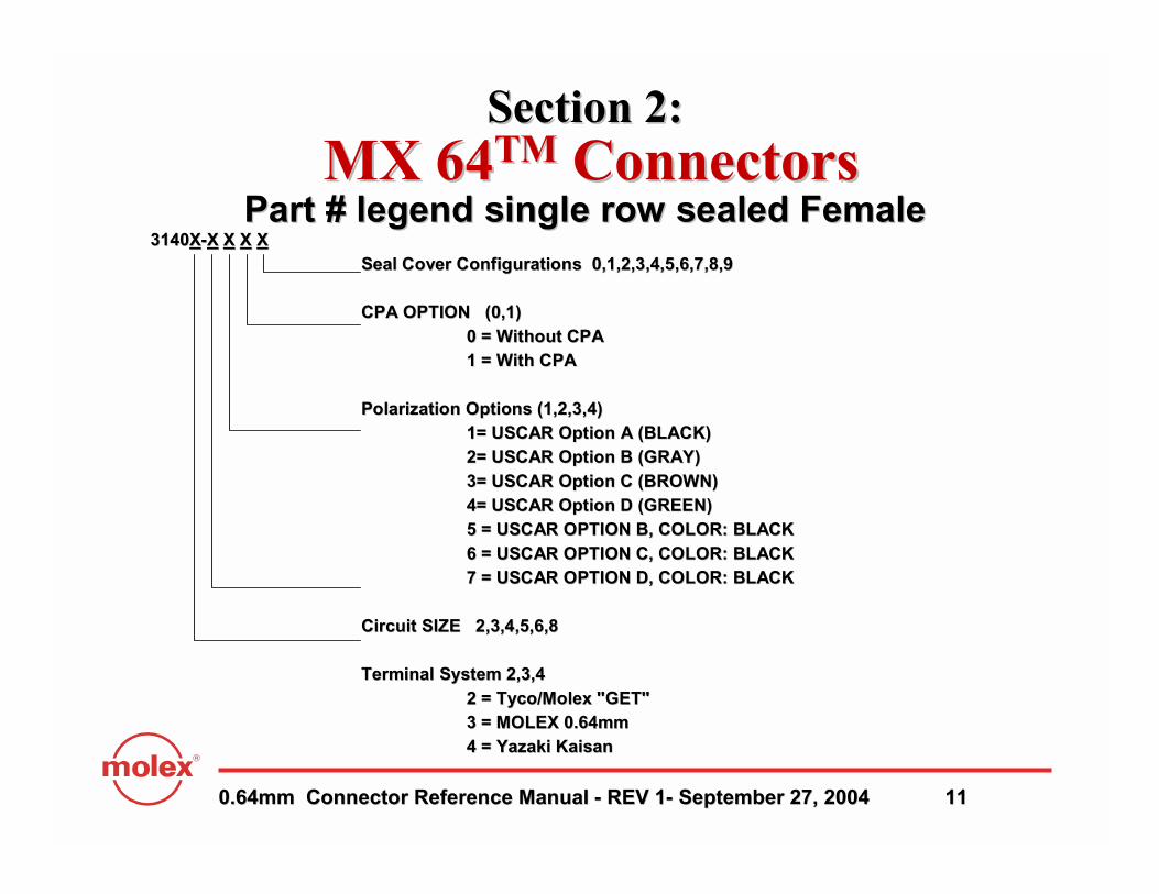
31403140XX--XX XX XX XXSeal Cover Configurations 0,1,2,3,4,5,6,7,8,9Seal Cover Configurations 0,1,2,3,4,5,6,7,8,9
CPA OPTION (0,1)CPA OPTION (0,1)0 = Without CPA0 = Without CPA1 = With CPA1 = With CPA
Polarization Options (1,2,3,4)Polarization Options (1,2,3,4)1= USCAR Option A (BLACK)1= USCAR Option A (BLACK)2= USCAR Option B (GRAY)2= USCAR Option B (GRAY)3= USCAR Option C (BROWN)3= USCAR Option C (BROWN)4= USCAR Option D (GREEN)4= USCAR Option D (GREEN)5 = USCAR OPTION B, COLOR: BLACK5 = USCAR OPTION B, COLOR: BLACK6 = USCAR OPTION C, COLOR: BLACK6 = USCAR OPTION C, COLOR: BLACK7 = USCAR OPTION D, COLOR: BLACK7 = USCAR OPTION D, COLOR: BLACK
Circuit SIZE 2,3,4,5,6,8Circuit SIZE 2,3,4,5,6,8
Terminal System 2,3,4Terminal System 2,3,42 = Tyco/Molex "GET"2 = Tyco/Molex "GET"3 = MOLEX 0.64mm3 = MOLEX 0.64mm4 = Yazaki 4 = Yazaki KaisanKaisan
Part # legend single row sealed FemalePart # legend single row sealed Female
Section 2:Section 2:MX 64MX 64TMTM ConnectorsConnectors

0.64mm Connector Reference Manual 0.64mm Connector Reference Manual -- REV 1REV 1-- September 27, 2004September 27, 2004 1212
Section 2:Section 2:MX 64MX 64TMTM ConnectorsConnectors
Molex MX64 0.64mmMolex MX64 0.64mm Tyco/Molex “GET” 0.064mmTyco/Molex “GET” 0.064mm Yazaki Kaisan 0.64mmYazaki Kaisan 0.64mm
0.64mm Connector Reference Manual 0.64mm Connector Reference Manual -- REV 1REV 1-- September 27, 2004September 27, 2004 1313
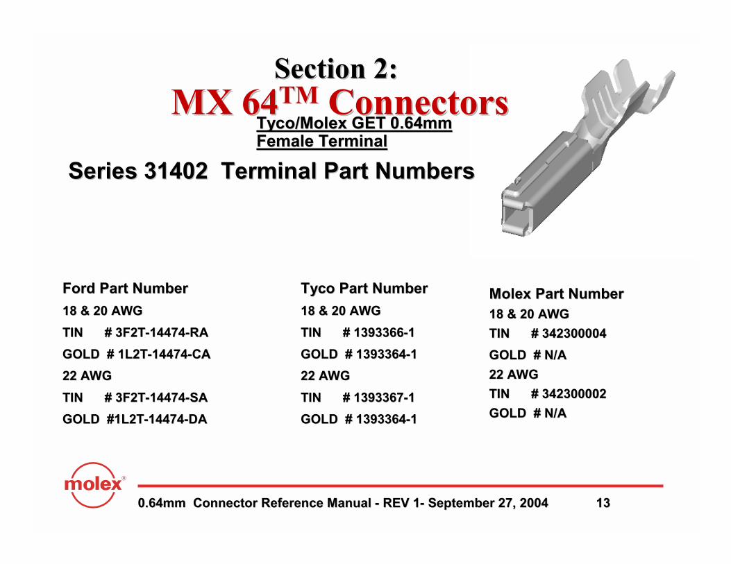
Tyco/Molex GET 0.64mm Tyco/Molex GET 0.64mm Female TerminalFemale Terminal
Orientation TabOrientation Tab
Molex Part NumberMolex Part Number18 & 20 AWG18 & 20 AWG
TIN # 342300004TIN # 342300004
GOLD # N/AGOLD # N/A
22 AWG22 AWG
TIN # 342300002TIN # 342300002
GOLD # N/AGOLD # N/A
Ford Part NumberFord Part Number
18 & 20 AWG18 & 20 AWG
TIN # 3F2TTIN # 3F2T--1447414474--RARA
GOLD # 1L2TGOLD # 1L2T--1447414474--CACA
22 AWG22 AWG
TIN # 3F2TTIN # 3F2T--1447414474--SASA
GOLD #1L2TGOLD #1L2T--1447414474--DADA
Tyco Part NumberTyco Part Number
18 & 20 AWG18 & 20 AWG
TIN # 1393366TIN # 1393366--11
GOLD # 1393364GOLD # 1393364--11
22 AWG22 AWG
TIN # 1393367TIN # 1393367--11
GOLD # 1393364GOLD # 1393364--11
Section 2:Section 2:MX 64MX 64TMTM ConnectorsConnectors
Series 31402 Terminal Part NumbersSeries 31402 Terminal Part Numbers

0.64mm Connector Reference Manual 0.64mm Connector Reference Manual -- REV 1REV 1-- September 27, 2004September 27, 2004 1414
Section 2:Section 2:MX 64MX 64TMTM ConnectorsConnectors
Tyco/Molex GET 0.64mm Female Tyco/Molex GET 0.64mm Female Terminal Series 31402Terminal Series 31402
Orientation TabOrientation Tab
Terminal Insertion Orientation to Grommet Seal CoverTerminal Insertion Orientation to Grommet Seal Cover
Correct OrientationCorrect Orientation90 Misorientation90 Misorientation
LockLock--outout180 Misorientation180 Misorientation
LockLock--outout

0.64mm Connector Reference Manual 0.64mm Connector Reference Manual -- REV 1REV 1-- September 27, 2004September 27, 2004 1515
Section 2:Section 2:MX 64MX 64TMTM ConnectorsConnectors
Molex 0.64mm Female Molex 0.64mm Female Terminal Series 31403Terminal Series 31403
Orientation TabOrientation Tab
MOLEX Part NumberMOLEX Part Number18 & 20 AWG 18 & 20 AWG
TIN TIN # 33468# 33468--00030003
GOLD # 33467GOLD # 33467--00050005
22 AWG22 AWG
TIN # 33468TIN # 33468--00010001
GOLD # 33467GOLD # 33467--00030003
Series 31403 Terminal Part NumbersSeries 31403 Terminal Part Numbers

0.64mm Connector Reference Manual 0.64mm Connector Reference Manual -- REV 1REV 1-- September 27, 2004September 27, 2004 1616
Section 2:Section 2:MX 64MX 64TMTM ConnectorsConnectors
Molex 0.64mm Female Molex 0.64mm Female Terminal Series 31403 Terminal Series 31403
Correct Orientation 90° MisorientationLock-out
180° MisorientationLock-out
Orientation TabOrientation Tab
Terminal Insertion Orientation to Grommet Seal CoverTerminal Insertion Orientation to Grommet Seal Cover

0.64mm Connector Reference Manual 0.64mm Connector Reference Manual -- REV 1REV 1-- September 27, 2004September 27, 2004 1717
Section 2:Section 2:MX 64MX 64TMTM ConnectorsConnectors
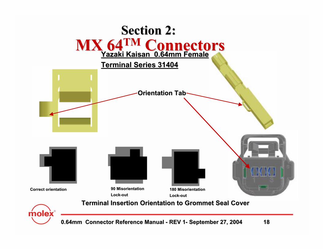
YazakiYazaki Kaisan Kaisan 0.64mm Female 0.64mm Female Terminal Series 31404Terminal Series 31404
Orientation TabOrientation Tab
YazakiYazaki Kaisan Kaisan 0.64mm0.64mm18 AWG18 AWG
TIN # TIN # 71167116--46194619--0202
AU # AU # 71167116--46194619--0808
20 & 22 AWG20 & 22 AWG
TIN # TIN # 71167116--46184618--0202
AU # AU # 71167116--46184618--0808
Series 31404 Terminal Part NumbersSeries 31404 Terminal Part Numbers
0.64mm Connector Reference Manual 0.64mm Connector Reference Manual -- REV 1REV 1-- September 27, 2004September 27, 2004 1818
Section 2:Section 2:MX 64MX 64TMTM ConnectorsConnectors
Orientation TabOrientation Tab
Terminal Insertion Orientation to Grommet Seal CoverTerminal Insertion Orientation to Grommet Seal Cover
Correct orientationCorrect orientation 90 Misorientation90 Misorientation
LockLock--outout180 Misorientation180 Misorientation
LockLock--outout
Yazaki Kaisan 0.64mm Female Yazaki Kaisan 0.64mm Female Terminal Series 31404Terminal Series 31404

0.64mm Connector Reference Manual 0.64mm Connector Reference Manual -- REV 1REV 1-- September 27, 2004September 27, 2004 1919
Section 3Section 3
Harness Assembly InstructionsHarness Assembly Instructions

0.64mm Connector Reference Manual 0.64mm Connector Reference Manual -- REV 1REV 1-- September 27, 2004September 27, 2004 2020
Section 3: Harness Assembly InstructionsSection 3: Harness Assembly InstructionsA. TPA shown in A. TPA shown in ““AsAs--ShippedShipped”” position (FIG. 3position (FIG. 3--1)1)
nn TPA shown TPA shown ““LOCKEDLOCKED”” position (FIG. 3position (FIG. 3--2)2)
nn TPA to remain in preTPA to remain in pre--lock position (as shipped) until all circuits are lock position (as shipped) until all circuits are loaded (Fig. 3loaded (Fig. 3--1)1)
Section Views of TPA in “PreSection Views of TPA in “Pre--Lock”and “Lock” PositionsLock”and “Lock” Positions
Fig. 3Fig. 3--22Fig. 3Fig. 3--11
TPATPA

0.64mm Connector Reference Manual 0.64mm Connector Reference Manual -- REV 1REV 1-- September 27, 2004September 27, 2004 2121
Section 3: Harness Assembly InstructionsSection 3: Harness Assembly Instructions
TPA must be in prelock position to install terminals!TPA must be in prelock position to install terminals!
nn PHOTOPHOTO nn PHOTOPHOTO
TPA in prelockTPA in prelock TPA lockedTPA lockedAS SHIPPEDAS SHIPPED

0.64mm Connector Reference Manual 0.64mm Connector Reference Manual -- REV 1REV 1-- September 27, 2004September 27, 2004 2222
Section 3: Harness Assembly InstructionsSection 3: Harness Assembly Instructions22--3 way connectors3 way connectors
nn TPA must be in preTPA must be in pre--lock position to install terminals!lock position to install terminals!
nn If TPA is locked you must move it to the preIf TPA is locked you must move it to the pre--lock position by lock position by carefully lifting up on the upper side of the TPA using a carefully lifting up on the upper side of the TPA using a 3.53.5 mm flat mm flat blade screw driver. This must be done as shown in FIG. 3blade screw driver. This must be done as shown in FIG. 3--66
nn DO NOT PRY ON THE LATCH SIDE OF THE CONNECTORDO NOT PRY ON THE LATCH SIDE OF THE CONNECTOR This will This will damage the TPA and connector!damage the TPA and connector!
DO NOT PRY HEREDO NOT PRY HERE
LIFT HERELIFT HERE
FIG. 3FIG. 3--77FIG. 3FIG. 3--66
Screw driverScrew driver
0.64mm Connector Reference Manual 0.64mm Connector Reference Manual -- REV 1REV 1-- September 27, 2004September 27, 2004 2323
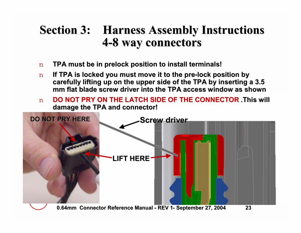
Section 3: Harness Assembly Instructions Section 3: Harness Assembly Instructions 44--8 way connectors8 way connectors
nn TPA must be in prelock position to install terminals!TPA must be in prelock position to install terminals!
nn If TPA is locked you must move it to the preIf TPA is locked you must move it to the pre--lock position by lock position by carefully lifting up on the upper side of the TPA by inserting acarefully lifting up on the upper side of the TPA by inserting a 3.53.5mm flat blade screw driver into the TPA access window as shown mm flat blade screw driver into the TPA access window as shown
nn DO NOT PRY ON THE LATCH SIDE OF THE CONNECTORDO NOT PRY ON THE LATCH SIDE OF THE CONNECTOR .This will .This will damage the TPA and connector!damage the TPA and connector!
DO NOT PRY HEREDO NOT PRY HERE
LIFT HERELIFT HERE
Screw driverScrew driver
0.64mm Connector Reference Manual 0.64mm Connector Reference Manual -- REV 1REV 1-- September 27, 2004September 27, 2004 2424
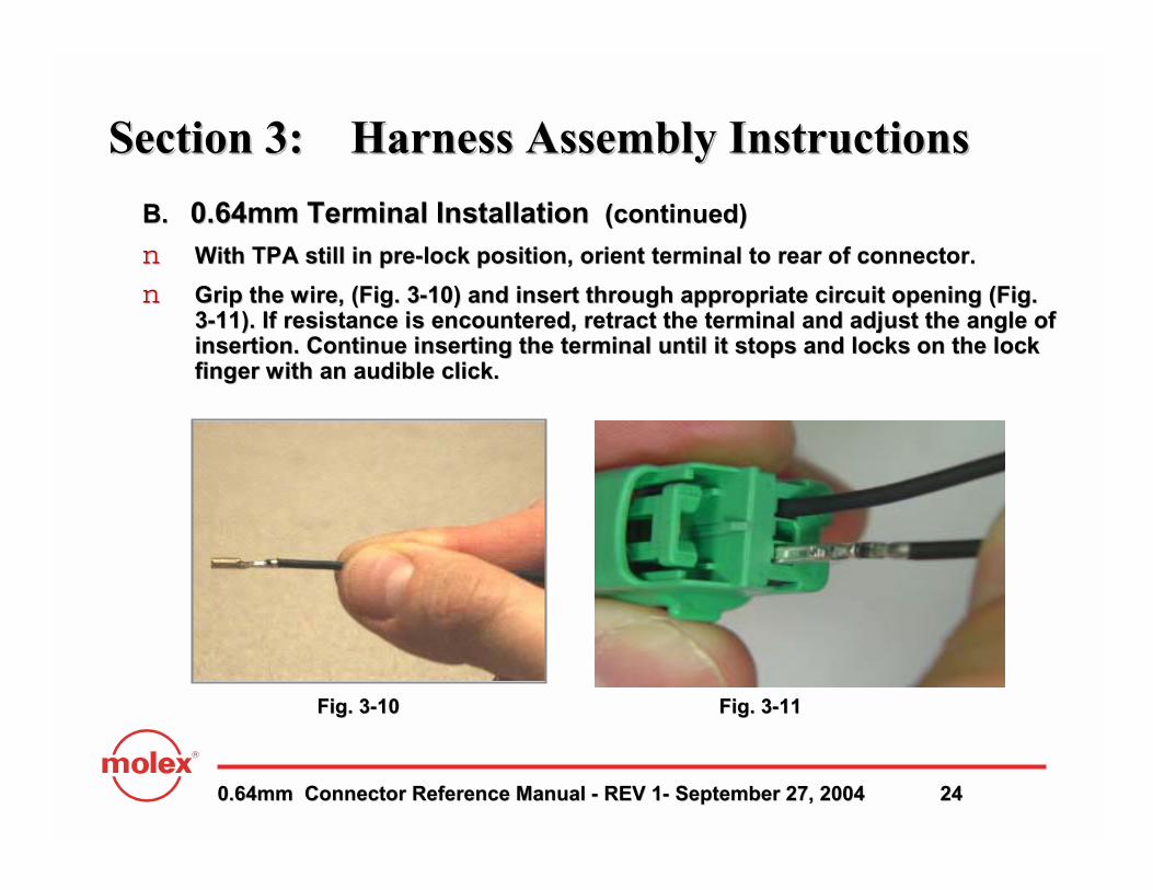
B.B. 0.64mm Terminal Installation 0.64mm Terminal Installation (continued)(continued)
nn With TPA still in preWith TPA still in pre--lock position, orient terminal to rear of connector. lock position, orient terminal to rear of connector.
nn Grip the wire, (Fig. 3Grip the wire, (Fig. 3--10) and insert through appropriate circuit opening (Fig. 10) and insert through appropriate circuit opening (Fig. 33--11). If resistance is encountered, retract the terminal and adju11). If resistance is encountered, retract the terminal and adjust the angle of st the angle of insertion. Continue inserting the terminal until it stops and loinsertion. Continue inserting the terminal until it stops and locks on the lock cks on the lock finger with an audible click. finger with an audible click.
Fig. 3Fig. 3--1010
Section 3: Harness Assembly InstructionsSection 3: Harness Assembly Instructions
Fig. 3Fig. 3--1111

0.64mm Connector Reference Manual 0.64mm Connector Reference Manual -- REV 1REV 1-- September 27, 2004September 27, 2004 2525
D. Seating TPA with the 0.64mm TerminalD. Seating TPA with the 0.64mm Terminal
nn With the terminals fully installed, the TPA can be seated into iWith the terminals fully installed, the TPA can be seated into its final lock ts final lock position by applying an even force (Fig. 3position by applying an even force (Fig. 3--12) until it comes to a stop and you 12) until it comes to a stop and you hear an audible click from the locking finger locking in place. hear an audible click from the locking finger locking in place. If the TPA If the TPA resists it may be detecting a partially installed terminal. Pulresists it may be detecting a partially installed terminal. Pull the TPA back l the TPA back into its preinto its pre--lock position and make sure all terminals are fully installed. lock position and make sure all terminals are fully installed. UponUponcompletion, the TPA can be seated. completion, the TPA can be seated.
Section 3: Harness Assembly InstructionsSection 3: Harness Assembly Instructions
Fig. 3Fig. 3--12 A&B12 A&B

0.64mm Connector Reference Manual 0.64mm Connector Reference Manual -- REV 1REV 1-- September 27, 2004September 27, 2004 2626
Section 3: Harness Assembly InstructionsSection 3: Harness Assembly Instructions
Completed ProductCompleted Product
0.64mm Connector Reference Manual 0.64mm Connector Reference Manual -- REV 1REV 1-- September 27, 2004September 27, 2004 2727
Section 4Section 4
Connector Mating InstructionsConnector Mating Instructions

0.64mm Connector Reference Manual 0.64mm Connector Reference Manual -- REV 1REV 1-- September 27, 2004September 27, 2004 2828
Section 4: Connector Mating InstructionsSection 4: Connector Mating Instructions
AA. Connector polarization options & color identification. Connector polarization options & color identification
USCAR Option A (BLACK)USCAR Option A (BLACK)
USCAR Option USCAR Option B (GRAY)B (GRAY)
USCAR Option USCAR Option C (BROWN)C (BROWN)
USCAR Option USCAR Option D (GREEN) D (GREEN)
Special request Option B,C& D (BLACK)Special request Option B,C& D (BLACK)
For updated polarization options consult. For updated polarization options consult. HTTP://WWW.USCARTEAMS.ORGHTTP://WWW.USCARTEAMS.ORG

0.64mm Connector Reference Manual 0.64mm Connector Reference Manual -- REV 1REV 1-- September 27, 2004September 27, 2004 2929
B. Connector matingB. Connector mating
nn Correctly orient the connector (align keying features) onto the Correctly orient the connector (align keying features) onto the mating mating connector (Fig. 4connector (Fig. 4--1) Then evenly push the connector onto the mating 1) Then evenly push the connector onto the mating connector until it locks with an audible click. (Fig. 4connector until it locks with an audible click. (Fig. 4--2).2).
Fig. 4Fig. 4--11 Fig. 4Fig. 4--22
Section 4: Connector Mating InstructionsSection 4: Connector Mating Instructions
Align Align Keying Keying FeaturesFeatures
Mated connector Mated connector
Align Align Keying Keying FeaturesFeatures
0.64mm Connector Reference Manual 0.64mm Connector Reference Manual -- REV 1REV 1-- September 27, 2004September 27, 2004 3030
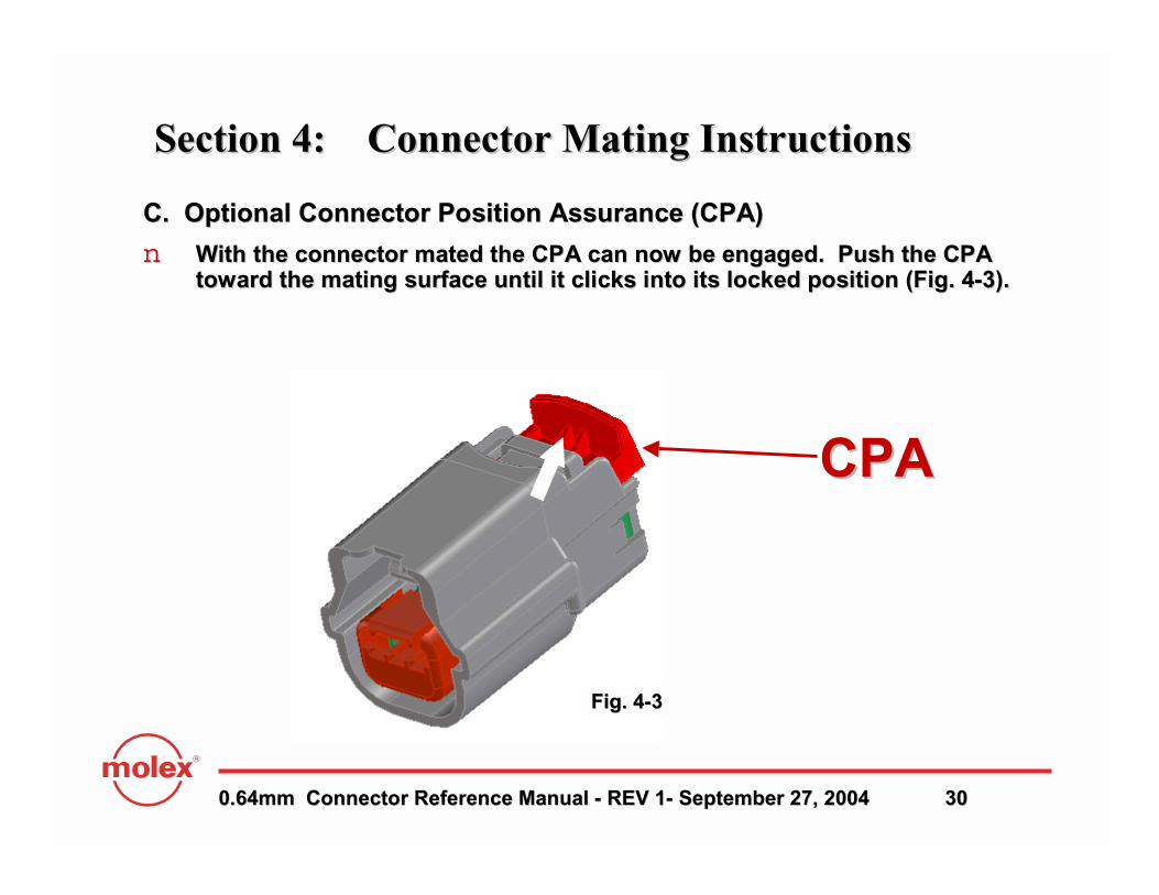
C. Optional Connector Position Assurance (CPA)C. Optional Connector Position Assurance (CPA)
nn With the connector mated the CPA can now be engaged. Push the CWith the connector mated the CPA can now be engaged. Push the CPA PA toward the mating surface until it clicks into its locked posititoward the mating surface until it clicks into its locked position (Fig. 4on (Fig. 4--3).3).
Fig. 4Fig. 4--33
Section 4: Connector Mating InstructionsSection 4: Connector Mating Instructions
CPACPA

0.64mm Connector Reference Manual 0.64mm Connector Reference Manual -- REV 1REV 1-- September 27, 2004September 27, 2004 3131
Section 5Section 5
Service InstructionsService Instructions
0.64mm Connector Reference Manual 0.64mm Connector Reference Manual -- REV 1REV 1-- September 27, 2004September 27, 2004 3232
Section 5: Service InstructionsSection 5: Service Instructions
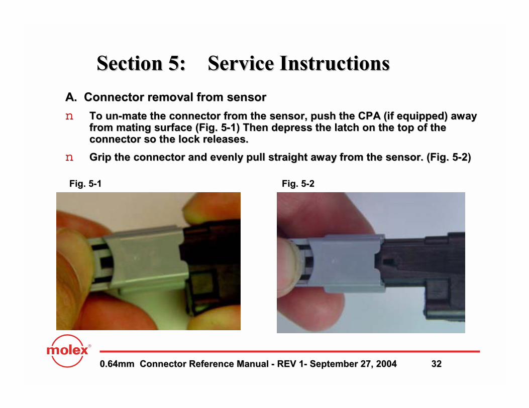
A. Connector removal from sensorA. Connector removal from sensor
nn To unTo un--mate the connector from the sensor, push the CPA (if equipped) amate the connector from the sensor, push the CPA (if equipped) away way from mating surface (Fig. 5from mating surface (Fig. 5--1) Then depress the latch on the top of the 1) Then depress the latch on the top of the connector so the lock releases. connector so the lock releases.
nn Grip the connector and evenly pull straight away from the sensorGrip the connector and evenly pull straight away from the sensor. (Fig. 5. (Fig. 5--2) 2)
Fig. 5Fig. 5--11 Fig. 5Fig. 5--22

0.64mm Connector Reference Manual 0.64mm Connector Reference Manual -- REV 1REV 1-- September 27, 2004September 27, 2004 3333
Section 5: Service InstructionsSection 5: Service Instructions
B. TPA ServicingB. TPA Servicing
nn Step 1: To add additional circuits move the TPA from locked to pStep 1: To add additional circuits move the TPA from locked to prere--lock as shown in section 3. lock as shown in section 3. Stop pulling when preStop pulling when pre--lock is reached.lock is reached.
nn Step 2: To remove circuits that have been populated you must remStep 2: To remove circuits that have been populated you must remove ove the TPA from the connector by raising it into prethe TPA from the connector by raising it into pre--lock and then lock and then continue raising until the TPA has been removed.continue raising until the TPA has been removed.
Step 1: Pry Up TPA Step 1: Pry Up TPA Fig. 5Fig. 5--33 Fig. 5Fig. 5--44

0.64mm Connector Reference Manual 0.64mm Connector Reference Manual -- REV 1REV 1-- September 27, 2004September 27, 2004 3434
Views of TPA in “PreViews of TPA in “Pre--Lock” PositionLock” Position
Section 5: Service InstructionsSection 5: Service Instructions
B. TPA Servicing (continued)B. TPA Servicing (continued)
TPATPA

0.64mm Connector Reference Manual 0.64mm Connector Reference Manual -- REV 1REV 1-- September 27, 2004September 27, 2004 3535
Section 5: Service InstructionsSection 5: Service InstructionsE. 0.64mm Terminal Removal E. 0.64mm Terminal Removal
nn After removing the TPA, Push up on the wire and carefully displaAfter removing the TPA, Push up on the wire and carefully displace the ce the locking finger using locking finger using 11mm blade screwdriver. Once the locking finger has mm blade screwdriver. Once the locking finger has been displaced gently pull on the wire to remove the terminal.been displaced gently pull on the wire to remove the terminal.
nn Do not use excessive force. Excessive force can damage the lockDo not use excessive force. Excessive force can damage the lock finger.finger.
nn Once the required terminals have been removed, Replace the TPA aOnce the required terminals have been removed, Replace the TPA and lock if nd lock if terminal population is complete.terminal population is complete.

0.64mm Connector Reference Manual 0.64mm Connector Reference Manual -- REV 1REV 1-- September 27, 2004September 27, 2004 3636
Section 5: Service InstructionsSection 5: Service InstructionsG.G. 0.64mm Terminal Removal (continued)0.64mm Terminal Removal (continued)
nn Do not use excessive force. Excessive force can damage the lockDo not use excessive force. Excessive force can damage the lockfinger.finger.
nn Deflect the top of locking finger to unlock it from the terminalDeflect the top of locking finger to unlock it from the terminal. Apply . Apply light pressure on lock finger while lightly pulling terminal wirlight pressure on lock finger while lightly pulling terminal wire.e.
Lock FingerLock Finger
Fig. 5Fig. 5--99
Female TerminalFemale Terminal
See page 36 for See page 36 for cross section viewcross section view
Screw driverScrew driver

0.64mm Connector Reference Manual 0.64mm Connector Reference Manual -- REV 1REV 1-- September 27, 2004September 27, 2004 3737
Section 5: Service InstructionsSection 5: Service InstructionsF. 0.64mm Terminal Removal F. 0.64mm Terminal Removal (continued)(continued)nn Carefully displace the locking finger by prying the lock fiCarefully displace the locking finger by prying the lock finger up to nger up to unlock it from the terminal. Use care not to over deflect the lounlock it from the terminal. Use care not to over deflect the lock finger to ck finger to avoid damage.avoid damage.
Insert 1mm Insert 1mm pry tool herepry tool here
Unlock finger to remove terminalUnlock finger to remove terminal
Cross sectioned for photographic purposeCross sectioned for photographic purpose

0.64mm Connector Reference Manual 0.64mm Connector Reference Manual -- REV 1REV 1-- September 27, 2004September 27, 2004 3838
Section 5: Service InstructionsSection 5: Service InstructionsF. 0.64mm Terminal Removal (continued)F. 0.64mm Terminal Removal (continued)
nn Once the terminal lock finger is disengaged, pull on the wire (FOnce the terminal lock finger is disengaged, pull on the wire (Fig. 5ig. 5--12) to release the terminal. 12) to release the terminal.
Fig. 5Fig. 5--1212

0.64mm Connector Reference Manual 0.64mm Connector Reference Manual -- REV 1REV 1-- September 27, 2004September 27, 2004 3939
Section 5: Service InstructionsSection 5: Service Instructions
G. MX0.64 Terminal Crimping G. MX0.64 Terminal Crimping nn If the 0.64mm terminal needs to be replaced, a new one can be haIf the 0.64mm terminal needs to be replaced, a new one can be handnd
crimped using the Molex Crimp Tool Number 63811crimped using the Molex Crimp Tool Number 63811--4200. Contact 4200. Contact Molex for terminal drawings, hand crimp instructions and crimp Molex for terminal drawings, hand crimp instructions and crimp height requirements.height requirements.
H. Tyco/Molex H. Tyco/Molex ““GETGET”” Terminal CrimpingTerminal Crimping
nn If the If the Tyco/Molex Tyco/Molex ““GETGET”” terminal needs to be replaced, a new terminal needs to be replaced, a new one can be hand crimped using the Molex crimp tool number one can be hand crimped using the Molex crimp tool number ..6381163811--4500 for the wire range: 0.224500 for the wire range: 0.22--0.35 mm2 & 220.35 mm2 & 22 awgawg. And . And 6381163811--4600 for the wire range: 0.504600 for the wire range: 0.50--0.75 mm2 & 200.75 mm2 & 20--1818 awgawg..Contact Molex for terminal drawings, hand crimp instructions andContact Molex for terminal drawings, hand crimp instructions andcrimp height requirements.crimp height requirements.
I. Yazaki I. Yazaki KaisanKaisan terminal crimpingterminal crimping
nn If the If the Yazaki Yazaki KaisanKaisan terminal needs to be replaced please consult terminal needs to be replaced please consult Yazaki for crimp tool information.Yazaki for crimp tool information.

0.64mm Connector Reference Manual 0.64mm Connector Reference Manual -- REV 1REV 1-- September 27, 2004September 27, 2004 4040
Section 6: Testing of terminalsSection 6: Testing of terminals
When testing the connector for continuity it is imperative that When testing the connector for continuity it is imperative that you do not you do not damage the terminals.damage the terminals.
Pogo pins should be checked for damage or sticking several timesPogo pins should be checked for damage or sticking several times aashift to assure Containment if an issue is found. shift to assure Containment if an issue is found.
First a visual inspection of all the pins for damage should be pFirst a visual inspection of all the pins for damage should be performed.erformed.
Next a testing block should depress all the pogo pins up into thNext a testing block should depress all the pogo pins up into the barrel. e barrel. If there is a bent or sticking pin it should get stuck up in theIf there is a bent or sticking pin it should get stuck up in the barrel barrel and must be replaced.and must be replaced.
Probing Damage can occur :Probing Damage can occur :
If a sharp ended probe is inserted into the contact of the conneIf a sharp ended probe is inserted into the contact of the connector it ctor it may damage the plating and increase contact resistance.may damage the plating and increase contact resistance.
If an oversize diameter probe is inserted into the terminal thisIf an oversize diameter probe is inserted into the terminal this will over will over deflect the beam in the terminal and create an environment for deflect the beam in the terminal and create an environment for intermittent connections and increased contact resistance.intermittent connections and increased contact resistance.
If a probe is inserted into the connector on an angle or off cenIf a probe is inserted into the connector on an angle or off center it may ter it may damage the terminal and/or connector.damage the terminal and/or connector.