mx51 cover gb -...
TRANSCRIPT

INSTRUCTIONS
MX51INDUSTRIAL MICROSCOPE
A X 7 5 9 5
This instruction manual is for the Olympus Industrial Microscope Model MX51.To ensure the safety,obtain optimum performance and to familiarize yourself fully with the use of this microscope, werecommend that you study this manual thoroughly before operating the microscope. Retain thisinstruction manual in an easily accessible place near the work desk for future reference.


MX51
CONTENTS
IMPORTANT — Be sure to read this section for safe use of the equipment. —
1 NOMENCLATURE
2 CONTROLS
3
4 USING THE CONTROLS
SUMMARY OF REFLECTED LIGHT BRIGHTFIELD/DARKFIELD OBSERVATION PROCEDURES
4-1 Frame ......................................................................................................................................................................................................... 15-16
4-2 Reflected Light Illuminator BX-RLA2/BX-KMA ................................................................................. 16-17
4-3 Stage ..................................................................................................................................................................................................................... 18
4-4 Observation Tube ..................................................................................................................................................................... 19-20
1 Adjusting the Illumination Brightness 2 Adjusting the Focusing
3 Adjusting the Coarse Adjustment Knob Tension 4 Pre-focusing Lever
5 Attaching/Detaching the Fine Adjustment Knob
1 Moving the MX-SIC6R2 Stage 2 Moving the U-SIC4R2/SIC4L2 Stage
1 Selecting the Observation Light Path 2 Controlling the Field Iris Diaphragm (FS)
3 Controlling the Aperture Iris Diaphragm (AS) 4 Using Filters
1-6
Correct assembly and adjustments are indispensable for the microscope to manifest its full performance. If youwant to assemble the microscope by yourself, see Chapter 10, “ASSEMBLY” (pages 33 to 45).For the modules for which separate instruction manuals are provided, also refer to the assembly description in theirmanuals..
1 Adjusting the Interpupillary Distance 2 Adjusting the Diopter
3 Using the Eye Shades 4 Using the Eyepiece Micrometer Disk
5 Selecting the Light Path of Trinocular Observation Tube
6 Adjusting the Tilt
5 PHOTOMICROGRAPHY 21
7
8-12
13-14
15-20


6 OBSERVATION 22-26
7 SPECIFICATIONS
8 OPTICAL CHARACTERSTICS <<UIS2 (UIS) Series>>
27
28-30
9 TROUBLESHOOTING GUIDE
6-1 Reflected Light Brightfield/Darkfield Observation ............................................................................. 22
6-2 Reflected Light Differential Interference Contrast (DIC) Observation ......... 23-24
6-3 Reflected Light Simplified Polarized Light Observation ........................................................... 25
6-4 Reflected Light Infrared (IR) Light Observation ...................................................................................... 25
6-5 Transmitted Light Brightfield Observation ..................................................................................................... 26
PROPER SELECTION OF THE POWER SUPPLY CORD ....................................................................... 47-48
31-32
33-4510
11
ASSEMBLY
10-1 Assembly Diagram ............................................................................................................................................................. 33-34
10-2 Detailed Assembly Procedures (Including Mercury Burner Centering) ..... 35-45
SPARE PART LIST 46
MX51

1
IMPORTANT
This microscope employs a UIS2 (UIS) (Universal Infinity System) optical design, and should be usedonly with UIS2 (UIS) eyepieces, objectives, observation tubes, etc. Less-than-optimal performance mayresult if inappropriate accessories are used.
SAFETY PRECAUTIONS
1. Always use the power cord provided by Olympus. If no power cord isprovided, please select the power cord by referring to the section “PROPERSELECTION OF THE POWER SUPPLY CORD” at the end of this instruc-tion manual. If the proper power cord is not used, Olympus can no longerwarrant the electrical safety performance of the equipment. Lay out thepower cord at a sufficient distance from the sources of heat such as thepower supply unit/light source and lamp housing to avoid contact withthese heat sources.
2. To avoid potential shock hazard, always set the main switch @ to “ ”(OFF) and disconnect the power cord before replacing the light sourcebulb/burner.
}Always use the lamp bulb or burner supplied by Olympus.
Fig. 1
Bulb/Burner Model Average Life
Halogen bulb · 6V30WHAL-L (Long life type) (HOSOBUCHI G4 20H CF-6)
2000 hrs.
· 6V30WHAL (High-intensity type) (PHILIPS 5761)
100 hrs.
· 12V100WHAL-L (Long life type) (PHILIPS 7724)
2000 hrs.
· 12V100HAL (High-intensity type) (PHILIPS 7023)
50 hrs.
Mercury burner · USH-103OL (USHIO) 300 hrs.
· HBO103W/2 (OSRAM)
300 hrs.
Xenon burner UXL-75XB-A(USHIO)
200 hrs.
Halogen bulb forlight guide lightsource
JCR12V-100WB(USHIO)
1000 hrs.
3. Do not light the mercury or xenon burner while it is not mounted on themicroscope because the UV rays in their light are harmful to your eyes.The used mercury burner should be disposed of as an industrial waste.If you cannot dispose of it properly, contact Olympus.
4. The eye point height cannot be adjusted with the standard observationtube (U-TR30-2) for this microscope. With this model, prepare the micro-scope table that can provide an eye point height between 1220 and13370 mm (SEMI S8-1103) from the floor surface.
@

2
MX51
5. The desktop surface on which the microscope system is installed should be almost horizontal with a tilting angle of lessthan 1° (to prevent spontaneous displacement of the stage) and rigid.(The weight of the microscope system with standard module combination is about 26 kg (57.3 lbs). )
}Although this microscope is designed with excellent vibration resistance, its maximum performance can be achievedwhen an anti-vibration bench is used.)
6. The lamp housing surface at the rear of the microscope frame will become very hot during operation. When installing themicroscope, ensure that there are ample free spaces (of more than 100 mm) around and in particular above and belowthe lamp housing. Also, the power cord and other cables should be laid out at distances from the microscope becausecontact with them may result in their fusion and an electric shock due to it.
7. To avoid a potential shock hazard, make sure that the power cord is safely grounded/earthed.8. To allow each microscope manifest its full performance, reserve an installation space having the minimum dimensions
described below before assembly and installation of the microscope. (Sizes in )}The dimensions of the area enclosed in alternate long and two short dashes lines indicate the stage movement range.
The dimensions marked * are variable depending on the lamp housing used.}When maintenance is required, a larger work space can be prepared by changing the observation tube orientation or
moving the stage.}The following installation space is set according to the SEMI standard guidelines (SEMI S8-1103). It is recommended that
you set the optimum installation space for each customer by referring to the following installation space data as well asthe appearance of the system, eye point height, etc.
Installation space
(358)
179 179
100
(588
)
209
379
100690
911
219
(113
0)
* (1290 (1178-1324))
MX51
Stage movementrange
Installation space
Unit: mm

3
(Note) The center of gravity is an approximate position when the microscope is equipped with the standard modulecombination for transmitted light observation. Note that the position is variable depending on the weight ofspecimen, position of the stage and other modules used.
External view, eye point and center of gravity
Unit: mmEye point
Position of center ofgravity
(Bottom view of microscope)
187
78 (Size of center of gravity)
185
275
*400 (288-434)
98
208
(Siz
e of
cen
ter o
f gra
vity
)
481
388 43
0 450
182133
(315)
270
(236
)
111
125
1630
78 (46)
18
18
7

4
MX51
9. To prevent toppling of the microscope system, keep the total height ofthe microscope below 1 meter (3.3 ft) when attachments (includingOlympus optional modules and the CCD camera prepared by the cus-tomer) are mounted.
Fig. 2
Symbol Explanation
l
Safety Symbols
The following symbols are found on the microscope. Study the meaning of the symbols and always use the equip-ment in the safest possible manner.
Indicates that the surface becomes hot, and should not be touched with bare hands.
Before use, carefully read the instruction manual. Improper use could result in personal injury tothe user and/or damage to the equipment.
Indicates that the main switch is ON.
Indicates that the main switch is OFF.
Caution indications
Caution indications are affixed at parts where special precaution is required when handling and using the microscope.Always heed the cautions.
Caution indicationpositions
Lamp housing/power supply unit[High temperature caution]
Light guide light source (LG-PS2)[High temperature caution]
159±0.1mm
Approx.13mm
@
10. The microscope has two screw holes (M5, depth 7 mm) for prevention oftoppling (in the case of an earthquake or microscope imbalance) on theside panel @. Clamp the microscope using L-shaped clamps and thesescrew holes as required.
!When clamping the microscope using L-shaped clamps preparedby the customer, be sure to use steel bolts (strength category12.9) with as long as possible threaded sections (6 mm or moreis recommended).

5
Fig. 3
1 Getting Ready
1. Do not use the microscope where it is subjected to direct sunlight, hightemperature and humidity, dust or vibrations. (For the operating condi-tions, refer to Chapter 7, “SPECIFICATIONS” on page 27.)
2. A microscope is a precision instrument. Handle it with care and avoidsubjecting it to sudden or severe impacts.When moving the microscope, detach the observation tube, stage andlamp housing to reduce the total system weight. Two persons are neededto carry the microscope; one should hold the base section and the otherperson should hold the arm section. (Fig. 3) (The microscope frame weightis about 11 kg (24.3 lbs). )
#Do not change the position of the microscope by sliding it on thedesktop surface; otherwise, the rubber feet will be damaged.
3. Be sure to attach the transport clamping plate(s) to the stage beforetransporting it.
2 Maintenance and Storage
1. To clean the lenses and other glass components, simply blow dirty away using a commercially available blower and wipegently using a piece of cleaning paper (or clean gauze).If a lens is stained with fingerprints or oil smudges, wipe it gauze slightly moistened with commercially available absolutealcohol.
!Since the absolute alcohol is highly flammable, it must be handled carefully.Be sure to keep it away from open flames or potential sources of electrical sparks –– for example, electricalequipment that is being switched on or off. Also remember to always use it only in a well-ventilated room.
2. If any part of the equipment (other than glass components) gets dirty, with it with a clean cloth.If the party is extremely dirty, do not attempt to use organic solvents to clean it; instead, use a soft, lint-free cloth slightlymoistened with a diluted neutral detergent.
3. Never disassemble any part other than instructed of the microscope. This could result in malfunctions or reducedperformance.
4. When not using the microscope, keep it covered with a dust cover. Make sure the lamp housing is cool before coveringthe microscope.
5. When disposing of the microscope, check the ordinances and rules of your local authority and follow them.
3 Applicable Standards
1. This device is in compliance with or certified by the following standards.2. Although this device is designed for use in industrial environments, their full performances may not be manifested if it is
not operated properly. Be sure to handle it properly as instructed in this manual.
This device is designed for use in industrial environments (Class A devices). Using itin a residential environment may affect other equipment in the environment.
CE marking
This device complies with the requirements of both directive 89/336/EEC concerning electromagnetic com-patibility and directive 73/23/EEC concerning low voltage. The CE marking indicates compliance with theabove directives.

6
MX51
FCC
This device has been subjected to the compliance evaluation of the following FCC regulation: · FCC Part 15, Subpart B: Radio Frequency Equipment (Commercial and industrial areas)
NOTE: This equipment has been tested and found to comply with the limits for a Class A digital device,pursuant to Part 15 of the FCC Rules. These limits are designed to provide reasonable protectionagainst harmful interference when the equipment is operated in a commercial environment. Thisequipment generates, uses, and can radiate radio frequency energy and, if not installed and used inaccordance with the instruction manual, may cause harmful interference to radio communications.Operation of this equipment in a residential area is likely to cause harmful interference in which casethe user will be required to correct the interference at his own expense.
FCC WARNING: Changes or modifications not expressly approved by the party responsible for compliancecould void the user’s authority to operate the equipment.
SEMI
This device has been subjected to the compliance evaluations of the following guidelines under the S8 Standard. · S2-0703: Safety Guidelines for Semiconductor Manufacturing Equipment · S8-1103: Safety Guidelines for Ergonomics Engineering of Semiconductor Manufacturing Equipment
The following symbols are used to set off text in this instruction manual.! : Indicates that failure to follow the instructions in the warning could result in bodily harm to the
user and/or damage to equipment (including objects in the vicinity of the equipment).# : Indicates that failure to follow the instructions could result in damage to equipment.} : Indicates commentary (for ease of operation and maintenance).
4 Caution
If the microscope is used in a manner not specified by this manual, the safety of the user may be imperiled. In addition,the equipment may also be damaged. Always use the equipment as outlined in this instruction manual.

7
1 NOMENCLATURE
}The illustration shows the MX51 composed of modules marked ·.The modules shown below are examples of those used in a typical system. Certain modules are usable even when they are notmentioned below. For these modules, refer to the latest catalogues or contact Olympus.For the modules marked *, refer to their instruction manuals.
Eyepieces
· WHN/WH Series (FN 22) SWH Series (FN 26.5)
Intermediateattachment **
Revolving Nosepiece
U-5RE-2U-P5BDREU-D6REU-D5BDRE
· U-D6BDREU-P4RE
Microscope Frame
· MX51-F
Observation Tube
U-BI30-2 (FN 22) ·U-TR30-2 (FN 22)
U-ETR3 (FN 22)U-SWTR-3 (FN 26.5)MX-SWETTR (FN 26.5)
Reflected Light Illuminator
BX-KMA * (Used in combinationwith the U-LS30-4/TL4)
·BX-RLA2 *BX-URA2 *
Lamp Housing(Applicable bulbs/burners)
· U-LH100L-3 (Halogen bulb)U-LH100HG/LH100HGAPO(Mercury burner)U-LH75XEAPO * (Xenon burner)
Stage
· MX-SIC6R2(Reflected/transmitted light)U-SIC4R2 (Reflected light)(Used in combination with theMX-STAD)U-SIC4L2 (Reflected light)(Used in combination with theMX-STAD)
Light Guide
· LG-SF
Light Source
· LG-PS2
Transmitted Light Module
·MX-TILLK
Objectives
· MPLFLN/MPLFLN-BD SeriesLMPLFLN/LMPLFLN-BD SeriesMPLN/MPLN-BD SeriesUMPlanFl/UMPlanFl-BD SeriesLMPlanFl/LMPlanFl-BD SeriesMPlanApo/MPlanApo-BD SeriesLMPlanApo/LMPlanApo-BD SeriesMPlan/MPlan-BD Series
** Only one intermediate attachment can be used: U-EPA2 * U-CA/ECA * U-DP * U-TRU *

8
MX51
CONTROLS
}If the microscope has not been assembled yet, refer to Chapter 10. “ASSEMBLY” (pages 33 to 45) first.The following illustration shows the modules of the model names enclosed inside . For other ancillary modules, read thesubsequent pages.
Trinocular Observation TubeU-TR30-2
Interpupillary distanceadjustment scale (Page 19)
Diopter adjustment ring(Page 19)
Mirror selector knob(Page 16)
ND filter lever (Page 22)
RevolvingNosepieceU-D6BDRE
Brightness adjustmentknob (Page 15)
Pilot lamp LED
Light path selector knob(Page 20)
Field iris diaphragm lever(Page 16)
Aperture iris diaphragm lever(Page 17)
Reflected Light IlluminatorBX-RLA2 *
Lamp Housing forHalogen BulbU-LH100L-3
6x6-Inch StageMX-SIC6R2
X-axis/Y-axis knobs(Page 18)
Coarse movement grip(Page 18)
(with clutch)
Left: Main switch (Page 15)
I : ON. “ ”: OFF.
Fine adjustment knob (Page 15)Coarse adjustment knob (Page 15)
Coarse adjustment knob tensionadjustment ring (Page 15)
Left: Pre-focusing lever (Page 15)
* For details on the BX-RLA2, refer to its instruction manual.

9
Stage and Holder System
Rotary Wafer HolderBH2-WHR43 (For 3-4 inch wafers)BH2-WHR54 (For 4-5 inch wafers)BH2-WHR65 (For 5-6 inch wafers)
* The U-MSSP4 stage plate come with two bend prevention pins attached at the factory before shipment. Besure to remove these pins before installation.
Rotary Wafer Holder PlateBH3-WHP6
4-Inch Mask HolderBH3-MH4
Black PlateBH3-SP6
Glass PlateBH3-SPG6
X-axis/Y-axis knobs(Page 18)
6x6-Inch StageMX-SIC6R2
Coarse adjustment knob(Page 18) (With grip)
Rotary Wafer HolderBH2-WHR43
Wafer Holder PlateU-WHP2
Stage PlateU-MSSP4 *
4x4-Inch StageU-SIC4R2/SIC4L2
X-axis/Y-axis knobs(Page 18)
Stage AdapterMX-STAD

10
MX51
Reflected Light IlluminatorBX-KMA
Filter insertion slots (Page 17)
# The filters should be insertedfrom the opposite side.
Analyzer insertion slot (Page 23)Polarizer insertion slot (Page 23)
Connection cableconnector
Lamp SocketU-LS30-4 }The applicable halogen bulbs are the 6V30WHAL-L/6V30WHAL.
Guide pins
Bulb Mounting Hole
Bulb Socket Pin
Power SupplyTL4 } For details, refer to the instruction manual.
Brightness control knob
Main switch
I : ON. “ ” : OFF.
Lamp socket connector
11
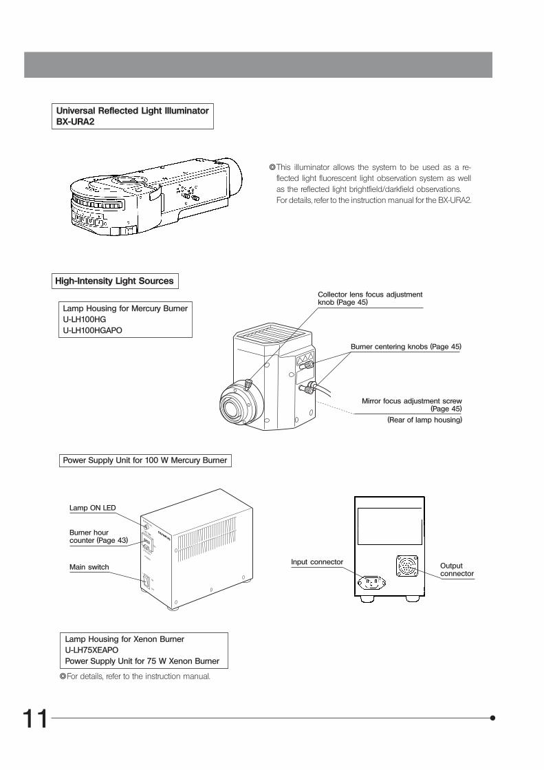
Universal Reflected Light IlluminatorBX-URA2
}This illuminator allows the system to be used as a re-flected light fluorescent light observation system as wellas the reflected light brightfield/darkfield observations.For details, refer to the instruction manual for the BX-URA2.
High-Intensity Light Sources
Lamp Housing for Mercury BurnerU-LH100HGU-LH100HGAPO
Collector lens focus adjustmentknob (Page 45)
Burner centering knobs (Page 45)
Mirror focus adjustment screw(Page 45)
(Rear of lamp housing)
Power Supply Unit for 100 W Mercury Burner
Lamp ON LED
Burner hourcounter (Page 43)
Main switchInput connector Output
connector
}For details, refer to the instruction manual.
Lamp Housing for Xenon BurnerU-LH75XEAPOPower Supply Unit for 75 W Xenon Burner

12
MX51
Transmitted Light ModuleMX-TILLK
Condenser lens
Light GuideLG-SF
Light SourceLG-PS2 }For details, refer to the instruction manual.
Stage clamping screws
x 4
Light guide insertion slot
Unit clamping screw holes
Light guide clamping screw

13
SUMMARY OF REFLECTED LIGHT BRIGHTFIELD/DARKFIELD OBSERVATION PROCEDURES
}This chapter outlines the operational procedure when the microscope is used for reflected light brightfield and darkfieldobservation. Other observation procedures such as differential interference contrast (DIC) observation are explained inseparate sections later in this manual.(Note) The BX-KMA reflected light illuminator cannot be used in the reflected light darkfield observation.
(Controls Used) (Page)
Select the brightfield (BF) or darkfield (DF) ob-servation.
Set the main switch to “ I ” (ON).
Disengage the analyzer, polarizer,filter, etc. from the light path.
Check interlocking of the ND filter.
Select the light path (trinocular tube only).
Place the specimen on the stage.
Engage the 10X objective in the light path.
Bring the specimen in focus.
Adjust the brightness.
Adjust the interpupillary distance.Adjust the diopter.
Adjust the aperture iris diaphragm and field irisdiaphragm.} Open both iris diaphragms in case of DF ob-
servation.
Engage the desired objective in the light pathand bring the specimen in focus.
Insert the required filters.
Adjust the brightness.
Start observation.
@ Mirror selector lever (P. 22)
² Main switch (P. 15)
³ ND filter (P. 22)
| Light path selector knob (P. 20)
ƒ Stage holder (P. 9/36/37)… X/Y-axis knobs (P. 18)
† Revolving nosepiece
‡ Coarse/fine adjustment knobs (P. 15)
Š Brightness adjustment knob (P. 15)
‰ Binocular tube (P. 19)‹ Diopter adjustment ring (P. 19)
Œ AS lever (P. 17)™ FS lever (P. 16)
† Revolving nosepiece‡ Coarse/fine adjustment knobs (P. 15)
š Filter insertion slot (P. 17)
Š Brightness adjustment knob (P. 15)

14
MX51
3 ™
@
a
b
4 c
7
5
9
8 2
e
6
Insert from theleft side.
Located on theleft side.
}Make a photocopy of this chapter and post it near the microscope for quick reference.

15
Fig. 4
USING THE CONTROLS
4-1 Frame
1 Adjusting the Illumination Brightness (Figs. 4 & 5)
Power Supply TL4
1. Confirm that the brightness control knob @ is set to the MIN (low Voltage)position, and set the main switch ² of the power supply to “ I ” (ON).
2. Turning the knob @ toward MAX (high Voltage) increases the light inten-sity and increases the illumination brightness.
Fig. 5
Fig. 6
Fig. 7
Power Supply Built Into the Microscope
1. Turn the Brightness adjustment knob ³ fully counterclockwise to the lowBrightness position, and then set the main switch | to “ I ” (ON).Confirm that the pilot lamp LED 5 lights up.
2. When the Brightness adjustment knob is turned clockwise to the highBrightness position, the light intensity increases.
}During photomicrography (in the position), the Brightness adjustmentknob cannot be used to adjust the light intensity without altering thecolor temperature of the light, too. Consequently, use ND filters to adjustthe light intensity during photomicrography.
2 Adjusting the Focus (Fig. 6)
When turning the coarse adjustment knob @ and fine adjustment knob² in the direction of the arrow, the stage is raised (the specimen is ad-vanced toward the objective).
3 Adjusting the Coarse Adjustment Knob Tension (Fig. 6)
The coarse adjustment knob tension is pre-adjusted for easy use. How-ever, if desired, you can change the tension using the tension adjustmentring ³. Turning the ring in the direction of the arrow increases tension,and vice versa.
#The tension is too low if the stage drops by itself or focus is quicklylost after adjustment with the fine adjustment knob. In this case, turnthe ring in the direction of the arrow to increase tension.
4 Pre-focusing Lever (Fig. 7)
The pre-focusing lever @ ensures that the objective does not come incontact with the specimen and simplifies focusing. After focusing on thespecimen with the coarse adjustment knob, turn this lever @ in the direc-tion of the arrow and lock there to set an upper limit on the coarse stagemovement.
#Stage movement with the fine adjustment knob is not affected bythe pre-focusing lever.
}After changing specimens, refocusing is easily accomplished y turningthe coarse adjustment knob to reach the pre-focusing position, thenmaking fine adjustment with the fine adjustment knob.
@
²
³|
5
@ ²³
@
16
MX51
Fig. 8
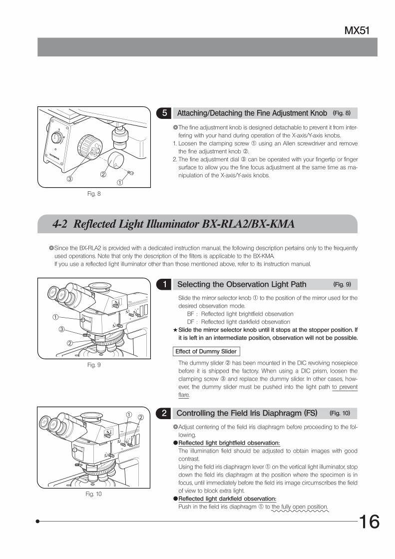
5 Attaching/Detaching the Fine Adjustment Knob (Fig. 8)
}The fine adjustment knob is designed detachable to prevent it from inter-fering with your hand during operation of the X-axis/Y-axis knobs.
1. Loosen the clamping screw @ using an Allen screwdriver and removethe fine adjustment knob ².
2. The fine adjustment dial ³ can be operated with your fingertip or fingersurface to allow you the fine focus adjustment at the same time as ma-nipulation of the X-axis/Y-axis knobs.
4-2 Reflected Light Illuminator BX-RLA2/BX-KMA
}Since the BX-RLA2 is provided with a dedicated instruction manual, the following description pertains only to the frequentlyused operations. Note that only the description of the filters is applicable to the BX-KMA.If you use a reflected light illuminator other than those mentioned above, refer to its instruction manual.
Fig. 9
1 Selecting the Observation Light Path (Fig. 9)
Slide the mirror selector knob @ to the position of the mirror used for thedesired observation mode.
BF : Reflected light brightfield observation DF : Reflected light darkfield observation#Slide the mirror selector knob until it stops at the stopper position. If
it is left in an intermediate position, observation will not be possible.
Effect of Dummy Slider
The dummy slider ² has been mounted in the DIC revolving nosepiecebefore it is shipped the factory. When using a DIC prism, loosen theclamping screw ³ and replace the dummy slider. In other cases, how-ever, the dummy slider must be pushed into the light path to preventflare.
Fig. 10
2 Controlling the Field Iris Diaphragm (FS) (Fig. 10)
}Adjust centering of the field iris diaphragm before proceeding to the fol-lowing.
{Reflected light brightfield observation:The illumination field should be adjusted to obtain images with goodcontrast.Using the field iris diaphragm lever @ on the vertical light illuminator, stopdown the field iris diaphragm at the position where the specimen is infocus, until immediately before the field iris image circumscribes the fieldof view to block extra light.
{Reflected light darkfield observation:Push in the field iris diaphragm @ to the fully open position.
@²
³
@
³
²
@ ²

17
Fig. 11
Fig. 12
3 Controlling the Aperture Iris Diaphragm (AS) (Figs. 10 & 11)
}The aperture iris diaphragm is used to adjust the aperture number of theillumination system. Matching the aperture number of the illuminationsystem with that of the objective in use offers an image with optimumcontrast and also increases the focal depth of image. But note that thisadjustment may decrease the resolution and brightness. In general, ad-justing the aperture iris to 70% to 80% of the objective can provide a well-balanced image.
}Adjust centering of the aperture iris diaphragm before proceeding to thefollowing.
{Reflected light brightfield observation:In general, remove the eyepieces, and then while looking into theeyepiece sleeves, pull out the aperture iris diaphragm lever ² tostop down to 70 to 80% of the numerical aperture of the objective toobtain good images. (Fig. 11)
{Reflected light darkfield observation:Push in the aperture iris diaphragm lever ² to the fully open position.
}Depending on the specimen, an image with good contrast and a mini-mum of flare may sometimes be obtained by keeping the aperture irisdiaphragm stopped down a little. Please experiment with this to see if itworks with a particular specimen.
4 Using the Filters (Fig.12)
}Engage the optimum filter sliders for the purpose of observation in thetwo filter insertion slots @. Be sure to start insertion with the left slot.The first click position is the idle position and the second click engagesthe filter in the light path.
Usable Filters Applications
U-25LBD-IF(Color temperatureconversion filter)
Turns the illumination light into daylight.Used in general observations and color pho-tography.
U-25IF550(Green filter)
Enhanced contrast in monochrome obser-vation.Used in monochrome photography.
U-25Y48(Yellow filter)
Contrast filter for observation of semicon-ductor wafers.
U-25ND25-2 (Lightintensity adjustment filter)
Adjusts the brightness of the light source.(Transmittance: 25%)
U-25ND6-2 (Lightintensity adjustment filter)
Adjusts the brightness of the light source.(Transmittance: 6%)
U-25FR(Frost filter)
Reduces irregularity in the illumination field,but also reduces the brightness.
U-25L42(UV cut filter)
Cuts ultraviolet rays. Used to prevent thepolarizer from being burned by a high-in-tensity light source.
U-25ND50-2 (Lightintensity adjustment filter)
Adjusts the brightness of the light source.(Transmittance: 50%)
Aperture iris image
70%
30%
@

18
MX51
Fig. 14
4-3 Stage
2 Moving the U-SIC4R2/SIC4L2 Stage (Fig. 14)
Rotate the X-axis knob @ and Y-axis knob ² to move the stage.The stage movement stroke in the X-axis direction is about 26 mm perturn of the knob and that in the Y-axis direction is about 42 mm per turnof the knob.
Using the Y-Axis Lock Lever
1. When the Y-axis lock lever ³ is locked by setting the lever in the directionof the arrow, the Y-axis movement is locked, making it possible to scanonly in the X-axis direction.
2. To release the lock, return the lever to the original position.
Maximum load of stages:
· Reflected light stage plate U-MSSP4: 1kg.
Fig. 13
1 Moving the MX-SIC6R2 Stage (Fig. 13)
Rotate the X-axis knob @ and Y-axis knob ² below right of the stage tomove the stage.The stage movement stroke in the X-axis direction is about 37 mm perturn of the knob and that in the Y-axis direction is about 50 mm per turnof the knob.
Using the Grip Clutch
By fully depressing the clutch | of the grip ³, the X-axis and Y-axisknobs can be coupled out.When the grip clutch is firmly depressed by your hand, you can move thestage greatly and freely at your will.
The clutch should be fully depressed. Neglecting this willcause the X-axis and Y-axis knobs to rotate abruptly andresult in damage.
CAUTION
Clutch and Belt Stickiness
If the stage is not moved for a long time, the clutch and the belt will sticktogether and the clutch function will not work smoothly.In this case, hold the X-axis and Y-axis knobs by hand to prevent themfrom rotating. Then fully depress the grip clutch and move the stage backand forth, left and right to remove the stickiness and get the clutch func-tion to work again.
Adjusting the Levelness of Holder Plate
The levelness of the stage travel (movement) and the top surface of thewafer holder have been adjusted at the factory. If finer adjustment is re-quired, contact Olympus.
Maximum loads of stage including the holders:
2 kg (4.4 lbs.)
@ ³²
@
|
²³

19
4-4 Observation Tube
Fig. 15
Fig. 16
Fig. 17
Fig. 18
1 Adjusting the Interpupillary Distance (Fig. 15)
While looking through the eyepieces, adjust for binocular vision until theleft and right fields of view coincide completely. The index dots “ · ” indi-cates the interpupillary distance. (Fig. 15)
}Note your interpupillary distance so that it can be quickly adjusted.
2 Adjusting the Diopter (Figs. 16 to 18)
When Using the Widefield Observation Tube (FN 22)
1. Looking through the right eyepiece with your right eye, turn the coarseand fine adjustment knobs to bring the specimen into focus.
2. Looking through the left eyepiece with your left eye, turn only the diopteradjustment ring @ to focus on the specimen. (Fig. 16)
When Using a Finder Eyepiece
1. Looking through the right eyepiece with your right eye, turn the top ofeyepiece ² until you see two distinct sets of reticules in the field of view.
(Figs. 16 & 17)2. Looking through the right eyepiece, rotate the coarse and fine adjust-
ment knobs to bring the specimen and reticules into simultaneous fo-cus.
(Fig. 17)3. Looking through the left eyepiece with your left eye, turn the diopter ad-
justment ring @ to bring the specimen into focus. (Fig. 16)
When Using the Super-Wide field Observation Tube (FN 26.5)
}The super-widefield observation tube refers to the U-SWTR-3 or MX-SWETTR.
1. Looking through the right finder eyepiece with your right eye, turn the topof the eyepiece ³ until you see two distinct sets of reticules and a clearlydefined double cross-lines in the field of view (Figs. 17 & 18)
2. Looking through the right eyepiece, rotate the coarse and fine adjust-ment knobs to bring the specimen and reticules into simultaneous fo-cus.
3. Looking through the left eyepiece with your left eye, turn the top of theeyepiece | to bring the specimen into focus. (Fig. 18)
@
²
³
|

20
MX51
Fig. 19
Fig. 20
3 Using the Eye Shades (Fig. 19)
When wearing eyeglasses
Use with the eyeshades in their normal folded-down position. This willprevent the eyeglasses from contacting and scratching the eyepieces.
When not wearing eyeglasses
Extended the folder eye shades in the direction of the arrow to preventextraneous light from entering between the eyepieces and eyes.
4 Using the Eyepiece Micrometer Disk (Fig. 20)
Eyepiece micrometer disk can be inserted into WHN10X-H (or WHN10X)eyepiece.However, if the eyepiece does not have the helicoid adjustment facilityand your eyesight is poor, you may have difficulties in focusing on theeyepiece micrometer disk. In this case, it is recommended to look intothe eyepiece through your eyeglasses.Use 24 mm dia., 1.5 mm thick micrometer disk.Following Fig. 20, turn the built-in micrometer mounting frame ² coun-terclockwise to remove it from the eyepiece, and place a micrometer disk @into the mounting frame so that the surface with indication faces down.Re-attach the micrometer mounting frame in the original position.
@
²
Fig. 21
5 Selecting the Light Path of the Trinocular Observation Tube (Fig. 21)
Slide the light path selector knob @ to select the desired light path.
TrinocularTube
Light Path Selector Position
Pushed In Intermediate Pulled Out
U-TR30-2
U-SWTR-3
U-ETR3
MX-SWETTR
Binocular 20%TV, photo 80%
TV, photo 100%
TV, photo 100%
Binocular 100%
Binocular 100%
Fig. 22
6 Adjusting the Tilt (Fig.22)
}Adjust the height and tilt of the eyepieces on the binocular observationtube to obtain the most comfortable viewing position.Holding the binocular section with both hands, raise or lower it to thedesired position.
· MX-SWETTR: 0° to 42°#Never attempt to force the binocular section past the upper or lower
stop position. Adjust the tilt gently, as applying excessive force coulddestroy the limiting mechanism.
@

21
CCD 1-inch
CCD 2/3-inch
CCD 1/2-inch
PHOTOMICROGRAPHY
}Use a trinocular observation tube, such as the U-TR30-2 or U-SWTR-3, when recording photographs, video images ordigital camera images of microscope images.The trinocular tube accepts the U-SPT straight photo tube or a TV adapter (certain TV adapters necessitate a cameramount adapter).For details, refer to the instruction manuals for these accessories.
1 Photomicrography System Chart
Trinocular observation tubeU-TR30-2U-ETR3U-SWTR-3MX-SWETTR
2 Selecting the TV Adapter Magnification
The magnification of the TV adapter is determined by the size of the CCD used in the TV camera or digital camera.The following illustrations show the image pickup areas of the 0.5X and 1X TV adapters when the WHN10X eyepieces (FN22) and the SWH10X eyepieces (FN 26.5) are used.
WHN10X (FN 22)
SWH10X (FN 26.5)
When a 0.5X TV adapter is used When a 1X TV adapter is used
Photomicrography unitTV camera ordigital camera
PE photo lens Camera mount adapter
Straight photo tubeU-SPT TV adapter

22
MX51
OBSERVATION
}The dummy slider in the DIC prism insertion slot is effective for preventing flare in observations other than the DIC observation.It is therefore recommended to leave it mounted in any observation method.
The operating procedure is variable depending on the reflected light illuminator in use. The following descrip-tion pertains only to the basic operating procedures for the BX-RLA2 and BX-URA2. For details, also refer to theinstruction manual for the illuminator.
NOTE
6-1 Reflected Light Brightfield/Darkfield Observation
Fig. 23
1 Selecting the Observation Light Path (Figs. 23 to 25)
BX-RLA2
Slide the mirror selector knob @ to the position of the mirror unit for thedesired observation mode.
BF: Reflected light brightfield observation (Adjust the aperture iris dia-phragm and field iris diaphragm as required.)
DF: Reflected light darkfield observation (Set the aperture iris diaphragmand field iris diaphragm to the open positions.)
#Slide the mirror selector knob until it stops at the stopper position.
<< Using the ND Filter Lever >>}When the brightfield (BF) light path is selected with the mirror selector
knob @, the ND filter is engaged in the light path by an interlock mecha-nism to reduce glare during switching from the darkfield (DF) to thebrightfield (BF). (Fig. 24)
How to Release the Interlock
}The ND filter has been interlocked with the mirror selector knob beforeshipment from the factory.
}If the brightness is insufficient during brightfield or DIC observation, theinterlocking of the ND filter can be released as described below.
1. After selecting the BF light path, insert the Allen screwdriver into the hole² on the left side of the reflected light illuminator and loosen the screwcoupling the ND filter.
2. Pull the ND filter lever ³ (Fig. 23) to disengage the ND filter from the lightpath, pull out the lever.
Fig. 25
BX-URA2
Rotate the turret | to the position to select the mirror unit (BF or DF) forthe desired observation mode.
|
@ ³
Inscription Mirror Unit Field Iris Aperture Iris
Reflected light brightfield
Reflected light darkfield
BF
DF
U-MBF3
U-MDF3
Adjust as required.
Must be open.
Fig. 24
@²

23
Fig. 26
Inscription Mirror Unit Note
Reflected light NomarskiDIC
BF U-MBF3
DIC U-MDIC3 Analyzer/polarizer built in
6-2 Reflected Light Differential Interference Contrast (DIC) Observation
#The performance of polarizer may deteriorate when it has been exposed to light for a long period (about continu-ous 2000 hours). If this happens, replace the polarizer.
#When performing sensitive color observation using the U-DICRH DIC slider, combine the U-POTP3 polarizer.#When using the high-intensity light source, be sure to use the U-25L42 filter for prevention of the polarizer burn.
1 Selecting the Observation Light Path
BX-RLA2
Select the reflected light brightfield observation (BF) light path.
BX-URA2
}When the DIC mirror unit (U-MDIC3) is available in the turret, engage theDIC mirror unit in the light path. The built-in analyzer and polarizer havebeen set for the cross-Nikol condition so they need not be adjusted.
2 Setting the Analyzer and Polarizer (Fig.26)
# In the cross-Nikol adjustment, do not engage the DIC slider (U-DICR,U-DICRH or U-DICRHC) in the light path.
1. Bring the specimen in approximate focus using the 10X or 20X objective.2. Engage the analyzer @ and polarizer ² in the light path.3. Rotate the analyzer rotating dial ³ to find the position where the field of
view is darkest.}An approximate cross-Nicol position can be obtained by setting the in-
dex on the dial ³ on the outer side, away from the microscope. Fine-adjust the dial by rotating it near this position to find the position wherethe field of view is darkest.
#Although the U-AN analyzer is also usable, the accurate cross-Nicolposition cannot be obtained because it is not provided with theanalyzer rotation mechanism.
BX-RLA2
@
²
³

24
MX51
Fig. 27
3 Setting the DIC Slider (Fig. 27)
1. Loosen the mounting knob @ on the front of the DIC revolving nose-piece, insert the DIC slider ² so that the surface with indication faces up,and clamp by tightening the mounting knob.
2. With the U-DICR interference slider, set the slide lever ³ according to theobjective in use.
@
²
³
|
BX-RLA2
3. With the U-DICRH or U-DICRHC slider that does not have the slide lever,the applicable objectives are as follows.
DIC Slider Applicable Objectives
U-DICRH MPLFLN/MPLFLN-BD series
UMPlanFl/UMPlanFl-BD seriesMPlanFl-BD seriesMPlanApo20X, 100X
U-DICRHC LMPLFLN/LMPLFLN-BD series
LMPlanFl/LMPlanFl-BD seriesLMPlanApo/LMPlanApo-BD series
UIS2
UIS
UIS2
UIS
4 Observation Method
1. Stop down the field iris diaphragm, and then move the stage up or downto focus on the iris. The specimen is brought into focus at the same time.
2. Adjust the field iris diaphragm so that it circumscribes the field of view.3. Stopping down the aperture iris diaphragm may increase the contrast
somewhat.
U-DICR U-DICRHC
1. Rotate the prism control knob | of the DIC slider to adjust the back-ground color contrast. (Fig. 27)
2. Rotating the prism control knob of the DIC slider will continuously changethe interference color of the background from gray to magenta (-100 to600 nm), so you can achieve the interference color with the best contrastaccording to the specimen.
· If the background color is gray, a three-dimensional looking image withmaximum contrast can be obtained.
· If the background color is magenta, even a minor optical retardation canbe observed as a color change.
Lever ³ position Applicable Objectives
Pushed in UIS2 MPLFLN/MPLFLN-BD series
UIS UMPlanFl/UMPlanFl-BD seriesMPlanApo20X, 100XMPlanApo100XBD
Pulled out UIS2 LMPLFLN/LMPLFLN-BD series
UIS LMPlanFl/LMPlanFl-BD seriesLMPlanApo/LMPlanApo-BD series

25
6-3 Reflected Light Simplified Polarized Light Observation
#The performance of polarizer may deteriorate when it has been exposed to light for a long period (about continu-ous 2000 hours). If this happens, replace the polarizer.
#When using the high-intensity light source, be sure to use the U-25L42 filter to prevent the polarizer burn.1. Set the analyzer and polarizer, and perform the cross-Nikol adjustment.2. Place the specimen on the stage and adjust the focus by moving the stage up or down. Now simplified polarized light
observation can be started.}Adjust the field iris diaphragm so that it circumscribes the field of view.}Stopping down the aperture iris diaphragm may increase the contrast somewhat.
6-4 Reflected Light Infrared (IR) Light Observation
}The vertical illuminator compatible with the IR observation is only the BX-RLA2.}Prepare a TV camera that matches the frequency of the IR light used.
( The IR light is harmful to your eyes. Be sure to observe the IR images on the TV monitor.)}To improve the IR observation effect, use as many IR-dedicated modules as possible (such as the lamp housing, objec-
tive, observation tube and TV adapter). For the IR-dedicated modules, contact Olympus.
Notes on the Use of IR Light
1. The IR light transmits a large quantity of heat on the specimen surface. Take sufficient care when observing a specimenthat is weak against heat.
2. When using the U-POIR reflected light polarizer, engage the U-25ND6-2 reflected light ND filter or the U-BP1100IR/BP1200IR band-pass filter for reflected IR light in the light path to prevent the polarizer burn.
3. Release the ND filter interlocking of the BX-RLA2 vertical illuminator during IR observation.4. With the U-TR30IR trinocular observation tube, the middle position of the 3-step light path selector is the position for the
shutter.
U-DICRH
1. Rotate the prism control knob @ of the DIC slider to adjust the back-ground color contrast. (Fig. 27)
2. Rotating the prism control knob of the DIC slider will continuously changethe interference color of the background from -100 to +100 nm, so youcan achieve the retardation with the best contrast according to the speci-men.
· If the background color is gray, a three-dimensional looking image withmaximum contrast can be obtained.
· If the background color is magenta, even a minor optical retardation canbe observed as a color change.To select the magenta sensitive color as the background color, use theU-POTP3 polarizer and insert it so that the indication “ ” can be seenfrom the front.
#Care should be taken to keep the specimen surface clean, as evena small amount of contamination on the surface may show up dueto the exceptionally high sensitivity of the DIC method.
}As the detection sensitivity is directional, it is recommended to use arotary wafer holder or rotate the specimen during observation.
}Stopping down the aperture iris diaphragm may increase the contrastsomewhat.

26
MX51
6-5 Transmitted Light Brightfield Observation
}This adjustment requires the MX-TILLK transmitted light unit,MX-SIC6R2 stage (for reflected and transmitted light), BH3-SPG6 glass plate, LG-SF light guide and LG-PS2 light source.
Fig. 28
1 Adjusting the Transmitted Light Illumination (Fig. 28)
1. Set the manual/remote switch @ of the light source to MANUAL.2. Set the main switch ² to “ I ” (ON). The ventilation fan will start running.
Now adjust the brightness by turning the brightness control knob ³,clockwise to increase the brightness or counterclockwise to decrease it.
#Turn the aperture iris diaphragm lever | counterclockwise to openthe aperture iris diaphragm.
}The aperture iris diaphragm lever | can be used to adjust the apertureiris diaphragm. But do not stop down the aperture iris diaphragm toomuch, as this may make illumination unevenness noticeable.
}When using a filter, mount the filter dedicated for the LG-PS2 (diameter30.5 mm) on the light source.Set the switch to “ " (OFF) for turning the light off. As the inside ofthe light source is very hot even after it has been turned off, leave itfor a while until it cools down sufficiently.
LG-PS2
2 Selecting the Observation Light Path
1. Select the reflected light darkfield observation (DF) light path.(The DF light path eliminates the half-mirror from the transmitted lightillumination path so that the transmitted light can be utilized by 100%.)
2. The applicable objective magnifications are 5X to 50X. When the 20X orhigher-power objective is used, however, the image may be a little darkdue to insufficiency in the NA.
3. The thickness of the transmitted light specimen should be no more than2 mm (provided that a 6 mm thick glass plate is used).
4. The area in which the transmitted light illumination is available is100 x 100 mm.
@²
³
|

27
SPECIFICATIONS
Item Specifications
Optical system UIS2 (UIS) (Universal Infinity System) op-tics
Illumination system Add-on type to the reflected light illumination microscope frame.
BX-KMADarkfield Reflected
Light Illuminator
BX-RLA2Brightfield/darkfield
reflected light illuminator
BX-URA2Universal reflected
light fluorescence illuminator
--Observation light path selection:BF · DF slide switch.
Observation light path selection:Turret selection of mirror unit (max.6 units)
Available observations:@ Reflected light brightfield² Reflected light Nomarski DIC³ Reflected light simplified polarized light
Available observations:@ Reflected light brightfield² Reflected light darkfield³ Reflected light DIC| Reflected light simplified polarized light5 Reflected light infrared observation6Transmitted light brightfield
Available observations:@ Reflected light brightfield² Reflected light darkfield³ Reflected light DIC| Reflected light simplified polarized light5 Reflected light fluorescent light6 Transmitted light brightfield
Lamp socket: U-LS30-4Power supply: TL4
Lamp housing for halogen bulb: U-LH100L-3. (Power supplied fromthe built-in power supply of the MX51.)High-intensity light source: Lamp housing for mercury/xenon burnermountable (together with a dedicated power supply).
Electrical system -- Rated input voltage: 100-120/220-240 V $, 1.8/0.8 A, 50/60 HzProvided with continuously variable brightness adjustment knob
Focusing mechanism Two-guide rack & pinion system.Coarse/fine coaxial adjustment knobs: Stroke 32 mm. (Distance from the stage surface to focal plane: 2 mm aboveand 30 mm below) (Note) The distance should be 15 mm below in the transmitted light brightfield observation.Fine adjustment knob stroke per rotation: 0.1 mm (1 µm per scale)Tension adjustment of coarse adjustment knob.Pre-focusing stopper for setting the upper limit.
Revolving nosepiece U-5RE-2, U-6RE, U-P4REU-D5BDRE, U-D6BDRE, U-P5BDRE (DIC slider insertion types)
Observation tube U-BI30-2Widefieldbinocular
U-TR30-2Widefieldtrinocular
U-ETR3Widefield
erected trinocular
U-SWTR-3Super-widefield
trinocular
MX-SWETTRSuper-widefielderected tilting
trinocular
FN 22 FN 26.5
Tube tilting angle: Fixed Tilting angle 0° to 42°
Interpupillary adjustment range: 50 to 76 mm
Stage U-SIC4R2/SIC4L24x4-inch stage with coaxial knobs on the bottom right (left).
MX-SIC6R26x6-inch stage with coaxial knobs on
the bottom right.
Drive method: Rack & pinion drive.Stroke: 100Y x 105X mmY-axis lock mechanism: Fixing in Y-axis direction using a lock lever.
Drive method: Rack & pinion drive.Stroke: 158Y x 158X mmClutch mechanism: Clutching and releaseusing two clutch plates (grip clutch)Holder hole size: 200+0.2/0 x 200+0.2/0 mm.Transmitted illumination field: 100 x 100 mm.
Operating Environment · Indoor use.· Altitude: Max. 2000 meters.· Ambient temperature:10° to 35°C (50° to 95° F).· Relative humidity: 80% for temperatures up to 31°C (88°F), decreasing linearly through 70% at 34°C
(93°F), 60% at 37°C (99°F) to 50% relative humidity at 40°C (104°F).· Supply voltage fluctuations: ±10%.· Pollution degree: 2 (in accordance with IEC60664).· Installation (overvoltage) category: II (in accordance with IEC60664)
Dimensions and weight Approx. 430 (W) x 495 (H) x 591 (D) mm.Approx. 26 kg (57.3 lbs) (Frame only: Approx. 11kg (24.3 lbs)).

28
MX51
Objective series
(PL = Plan)
OPTICAL CHARACTERISTICS «UIS2 (UIS) Series»
The table below shows the optical characteristics of different eyepieceand objective combinations. Objective specifications are marked onthe objective (as shown in the diagram on the right).
NOTE
Refer to the latest catalogue or consult Olympus for the updated infor-mation on the eyepieces and objectives that can be combined withthis unit.
Magnification
UIS marking
Cover glass thickness—: May be used with our
without a cover glass.0: Used without a cover glass.
-- The UIS series objectives that are not mentioned below can also be mounted on this microscope. --
FN (Field Number)
NA (Numerical Aperture)
Brightfield/darkfieldapplication
Opticalcharacteristics
Magnifi-cation N.A. W.D.
(mm)
Coverglassthickness(mm)
Resolu-tion(µm)
Eyepieces
Series
WHN10X (FN22) SWH10X (FN26.5)
Totalmag.
Depth of focus
(µm)
Fieldof view(mm)
Totalmag.
Depthof focus
(µm)
Fieldof view(mm)
MPLNPlan Achromat(FN22)
MPLN-BDBrightfield/darkfieldPlan Achromat(FN22)
5X 0.10 20.0 — 3.36 50X 98 4.410X 0.25 10.6 — 1.34 100X 18 2.220X 0.40 1.3 0 0.84 200X 6.1 1.1 — — —50X 0.75 0.38 0 0.45 500X 1.4 0.44
100X 0.90 0.21 0 0.37 1000X 0.73 0.225X 0.10 12.0 — 3.36 50X 98 4.4
10X 0.25 6.5 — 1.34 100X 18 2.220X 0.40 1.3 0 0.84 200X 6.1 1.1 — — —50X 0.75 0.38 0 0.45 500X 1.4 0.44
100X 0.90 0.21 0 0.37 1000X 0.73 0.22
Marking
MPlanN
MPlanN-BD
UIS2series
MPLFLNPlan Semi-Apochromat(FN26.5)*1.25X:FN22
MPlanFLN
MPLFLN-BDBrightfield/darkfieldPlan Semi-Apochromat(FN26.5)
MPlanFLN-BD
MPLFLN-BDPReflected PolarizedLight Plan Semi-Apochromat(FN26.5)
MPlanFLN-BDP
LMPLFLNLong-WD PlanSemi-Apochromat(FN26.5)
LMPlanFLN
LMPLFLN-BDBrightfield/darkfieldlong-WD Plan Semi-Apochromat(FN26.5)
LMPlanFLN-BD
1.25X 0.04 3.5 — 8.39 12.5X 870 17.6 — — —2.5X 0.08 10.7 — 4.19 25X 220 8.8 25X 220 10.6
5X 0.15 20.0 — 2.24 50X 59 4.4 50X 59 5.310X 0.30 11.0 — 1.12 100X 15 2.2 100X 15 2.6520X 0.45 3.1 0 0.75 200X 5.2 1.1 200X 5.2 1.3350X 0.80 1.0 0 0.42 500X 1.3 0.44 500X 1.3 0.53
100X 0.90 1.0 0 0.37 1000X 0.73 0.22 1000X 0.73 0.275X 0.15 12.0 — 2.24 50X 59 4.4 50X 59 5.3
10X 0.30 6.5 — 1.12 100X 15 2.2 100X 15 2.6520X 0.45 3.0 0 0.75 200X 5.2 1.1 200X 5.2 1.3350X 0.80 1.0 0 0.42 500X 1.3 0.44 500X 1.3 0.53
100X 0.90 1.0 0 0.37 1000X 0.73 0.22 1000X 0.73 0.27150X 0.90 1.0 0 0.37 1500X 0.6 0.15 1500X 0.6 0.18
5X 0.15 12.0 — 2.24 50X 59 4.4 50X 59 5.310X 0.25 6.5 — 1.34 100X 18 2.2 100X 18 2.6520X 0.40 3.0 0 0.84 200X 6.1 1.1 200X 6.1 1.3350X 0.75 1.0 0 0.45 500X 1.4 0.44 500X 1.4 0.53
100X 0.90 1.0 0 0.37 1000X 0.73 0.22 1000X 0.73 0.275X 0.13 22.5 — 2.58 50X 70 4.4 50X 70 5.3
10X 0.25 21.0 — 1.34 100X 18 2.2 100X 18 2.6520X 0.40 12.0 0 0.84 200X 6.1 1.1 200X 6.1 1.3350X 0.50 10.6 0 0.67 500X 2.5 0.44 500X 2.5 0.53
100X 0.80 3.4 0 0.42 1000X 0.87 0.22 1000X 0.87 0.275X 0.13 15.0 — 2.58 50X 70 4.4 50X 70 5.3
10X 0.25 10.0 — 1.34 100X 18 2.2 100X 18 2.6520X 0.40 12.0 0 0.84 200X 6.1 1.1 200X 6.1 1.3350X 0.50 10.6 0 0.67 500X 2.5 0.44 500X 2.5 0.53
100X 0.80 3.3 0 0.42 1000X 0.87 0.22 1000X 0.87 0.27
Note) When an MPLN-BD series objective is used in darkfield observation with a xenon light source, the peripheral areamay be obscured with certain specimens.

29
*Equipped with the glass thickness compensation ring.
Objectives for LCD Panel
UISseries
MPlanApoPlanApochromat
MPlanApo
MPlanApo-BDBrightfield/darkfieldPlan Apochromat
MPlanApo-BD
SLMPlanSuperlong-WDPlan Achromat(FN26.5)
SLMPlan
20X 0.60 0.9 0 0.56 200X 3.68 1.1 200X 3.68 1.3350X 0.95 0.3 0 0.35 500X 1.04 0.44 500X 1.04 0.53
100X 0.95 0.35 0 0.35 1000X 0.67 0.22 1000X 0.67 0.27
100X 0.90 0.31 0 0.37 1000X 0.73 0.22 1000X 0.73 0.27
20X 0.35 21.0 0 0.96 200X 7.2 1.1 200X 7.2 1.33
50X 0.45 15.0 0 0.75 500X 2.9 0.44 500X 2.9 0.53
Opticalcharacteristics
Magnifi-cation N.A. W.D.
(mm)
Coverglassthickness(mm)
Resolu-tion(µm)
Eyepieces
Series
WHN10X (FN22) SWH10X (FN26.5)
Totalmag.
Depth of focus
(µm)
Fieldof view(mm)
Totalmag.
Depthof focus
(µm)
Fieldof view(mm)Marking
UIS2series
LCPLFLNLong-WD PlanSemi-Apochromat(FN26.5)
LCPlanFLN* 20XLCD 0.45 7.4-8.3 0-1.2 0.75 200X 5.2 1.1 200X 5.2 1.3350XLCD 0.70 2.2-3 0-1.2 0.48 500X 1.6 0.44 500X 1.6 0.53
Opticalcharacteristics
Magnifi-cation N.A. W.D.
(mm)
Coverglassthickness(mm)
Resolu-tion(µm)
Eyepieces
Series
WHN10X (FN22) SWH10X (FN26.5)
Totalmag.
Depth of focus
(µm)
Fieldof view(mm)
Totalmag.
Depthof focus
(µm)
Fieldof view(mm)Marking
100XLCD 0.85 0.9-1.2 0-0.7 0.39 1000X 0.79 0.22 1000X 0.79 0.27

30
MX51
Significance of Objective Name
(Examples) M PL FL N 100 BD(Plan)
None : BrightfieldBD : DarkfieldBDP : Brightfield orpolarizedIR : IR light
Figure : Magnification
None : UISN : UIS 2
None : Achromat, or aberration correction with 2 wavelengths (red andbleu).
FL : Semi-Apochromat, or color aberration correction with visualwavelengths (bluish purple to red).
APO : Apochromat, or color aberration correction with all visual-domainwavelength (purple to red).
PL : Plan, or correction of image curving on peripheral area.
M : Metal observation (no cover)LM : Long-WD metal observationSLM : Superlong-WD metal observationLC : Observation over glass plate
Glossary of Terms Used in the Optical Characteristics Table
Working distance (WD) : The distance from the top of specimen and the front lens of objective.Number of aperture (NA) : Important figure determining the objective characteristics (resolution, focal depth and bright-
ness).Resolution ............. Increases in proportion with the NA.Focal depth ......... Decreases in proportion with the NA.Brightness ............. Proportional with the square of NA (comparison under the same magnification).
Resolution : The limit that an objective can identify the images of two points that are close to each other,expressed as the distance between the two points on the specimen.
Depth of focus : The maximum depth of the specimen at which the entire specimen can be brought into focussimultaneously. This value increases when the aperture iris diaphragm is narrowed and de-creases when the objective NA is increased.
Field number : The diameter of the image area that can be observed through the eyepieces, expressed in mm.

31
TROUBLESHOOTING GUIDE
Under certain conditions, performance of the microscope may be adversely affected by factors other than defects. Ifproblems occur, please review the following list and take remedial action as needed. If you cannot solve the problem afterchecking the entire list, please contact Olympus for assistance.
#Possible causes marked “ * ” at the top are not applicable to the BX-KMA.
Trouble Cause Remedy Page
1. Optical System
a) Although the illumination is on, thefield of view is dark or invisible.
The bulb is burned out. Replace it.
*The field iris diaphragm is opened in-sufficiently.
Open the field iris diaphragm.
*The aperture iris diaphragm is stoppeddown while the light path is set to thatcontaining a darkfield mirror or mirrorunit turret. (Reflected light brightfield/darkfield observation)
Fully open the aperture iris diaphragm.
The light path selector knob on the trin-ocular tube is stopped at the middleposition.
Set the knob to position or .
*The observation light path is set im-properly with the mirror selector knobor mirror unit turret.
Set the mirror selector knob or mirrorunit turret properly.
b) Field of view is obscured, or fieldof view is not evenly illuminated.
*The mercury or xenon burner is notcentered.
Adjust centering correctly.
The filter, analyzer or polarizer is notcorrectly inserted.
Insert or remove the filter, polarizer oranalyzer completely into or from thelight path.
The light path selector knob on the trin-ocular tube is stopped at the middleposition.
Set the knob properly.
*The observation light path is set im-properly with the mirror selector knobor mirror unit turret.
Set the mirror selector knob or mirrorunit turret properly.
c) Dirt or dust is visible in the field ofview.
Dirt/dust on the bulb/burner surface. Clean thoroughly.
Dirt/dust on the specimen.
Dirt/dust on the objective front lens.
Dirt/dust on the eyepiece.
Dirt/dust on the top lens of condenser.
d) The image shows diffraction. *The aperture iris diaphragm is stoppeddown too far.
Open the aperture iris diaphragm.
e) Visibility is poor.Image is not sharp.Contrast is poor.
The objective is not correctly engagedin the light path.
Make sure that revolving nosepiececlicks into place correctly.
The condenser or the front lens of ob-jective is dirty.
Clean thoroughly.
You are using a non-designated objec-tive or eyepieces.
Use the specified UIS2 (UIS) objec-tive or eyepieces.
39,40,42
16
17
20
22
45
17,23
20
22
5
17
--
5
28,29

32
MX51
Trouble Cause Remedy
f ) Part of image is blurred.The image seems to waver.
The specimen is not mounted horizon-tally.
Re-mount the specimen and holders.
The objective is not correctly engagedin the light path.
Make sure that revolving nosepiececlicks into place correctly.
Page
2. DIC Observation
a) No interference color. The analyzer and polarizer are not en-gaged. Another filter is engaged.
Engage the analyzer and polarizer inthe light path. Disengage another fil-ter from the light path.
b) Interference color appears but isuneven or contrast is low.
Proper objectives suitable for DIC ob-servation are not used.
Use proper objectives.
3. Observation Tube
The interpupillary distance is incorrect. Adjust the interpupillary distance.
Incorrect diopter adjustment. Adjust the diopter.
Different eyepieces are used on the leftand right.
Change one eyepiece to match theother so that both sides are the same.
Field of view of one eye does notmatch that of the other.
4. Stage
The image shifts when you touch thestage.
The stage and holders are not properlymounted.
Champ the stage and holders.
5. Coarse/Fine Adjustment Knobs
a) The coarse adjustment knob ishard to turn.
The coarse adjustment knob rotationtension adjustment ring is over-tight-ened.
Loosen the ring.
b) The stage drifts down by itself orfocus is lost during observation.
The coarse adjustment knob rotationtension adjustment ring is too loose.
Tighten the ring.
c) Coarse adjustment will not go allthe way up.
The pre-focusing lever is keeping thestage down.
Unlock the pre-focusing lever.
6. Electrical System
a) The lamp intermediately lights andgoes out.
The bulb is nearly burned out. Replace the bulb.
Improper cord connection. Connect cords and plugs correctly.
36,37
--
--
17,23
24
19
19
35,36
15
15
15
39,40,42
39,41,44

33
ASSEMBLY
10-1 Assembly Diagram
}The diagram below shows all of the various modules that can be mounted. Select only the modules to be used for theassembly.The assembly of modules enclosed in are detailed in Section 10-2. For the modules without numbers, refer to theirinstruction manuals.
#When assembling the equipment, make sure that all parts are free of dust and dirt and avoid scratching any partsor touching glass surfaces.
Observation tubeU-BI30-2 (FN 22)U-TR30-2 (FN 22)U-ETR3 (FN 22)U-SWTR-3 (FN 26.5)MX-SWETTR (FN 26.5)
EyepiecesWHN/WH Series (FN 22)SWH Series (FN 26.5)
Intermediate attachment(Only one of the followingcan be attached.)U-EPA2U-CA/ECAU-DPU-TRU, etc.
Revolving NosepieceU-5RE-2 (Brightfield)U-P5BDRE (Brightfield/darkfield)U-D6RE(Brightfield)U-D6BDRE (Brightfield/darkfield)
DIC sliderU-DICRU-DICRHU-DICRHC
Brightfield/darkfieldobjectives
ObjectiveadapterBD-M-AD
Brightfieldobjectives
For the filtersand analyzers,see next page.
Halogen bulb
Lamp housingfor halogenbulbU-LH100L-3
For the high-intensity lightsources, seenext page.
Reflected lightilluminatorBX-KMABX-RLA2BX-URA2
Microscope frameMX51-F
Reflected lightspacer
For holders, seepage 9.
StageMX-SIC6R2U-SIC4R2 *U-SIC4L2 *(* Used incombination withthe MX-STAD)
Transmittedlight moduleMX-TILLK(Attach byremoving thereflected lightspacer.)
Light guideLG-SF
Light sourceLG-PS2
Allen screwdriver (3 mm)
Allen wrench (3 mm)
Tool holder
Tools Used(Provided with the microscope frame)
}The tools used can be stored in the holes on the tool holder providedwith the microscope frame. Use the double-sided adhesive tape of thetool holder to attach it to a position that does not hinder operation.
!Do not attach the tool holder anywhere near the bottom of the lamphousing since it generates high-temperature heat.
34
MX51
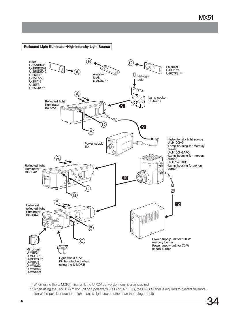
Reflected Light Illuminator/High-Intensity Light Source
FilterU-25ND6-2U-25ND25-2U-25ND50-2U-25LBDU-25IF550U-25Y48U-25FRU-25L42 **
AnalyzerU-ANU-AN360-3
PolarizerU-PO3 **U-POTP3 **
Reflected lightilluminatorBX-KMA
Halogenbulb
Lamp socketU-LS30-4
Power supplyTL4
Reflected lightilluminatorBX-RLA2
Universalreflected lightilluminatorBX-URA2
Mirror unitU-MBF3U-MDF3 *U-MDIC3 **U-MBFL3U-MWUS3U-MWBS3U-MWGS3
Light shield tube(To be attached whenusing the U-MDF3)
High-intensity light sourceU-LH100HG(Lamp housing for mercuryburner)U-LH100HGAPO(Lamp housing for mercuryburner)U-LH75XEAPO(Lamp housing for xenonburner)
Power supply unit for 100 Wmercury burnerPower supply unit for 75 Wxenon burner
* When using the U-MDF3 mirror unit, the U-RCV conversion lens is also required.** When using the U-MDIC3 mirror unit or a polarizer (U-PO3 or U-POTP3), the U-25L42 filter is required to prevent deteriora-
tion of the polarizer due to a high-intensity light source other than the halogen bulb.

35
Fig. 30
1. Turn the coarse adjustment knob @ in the direction of the arrow to lowerthe reflected light spacer ² to the lower limit. (Fig. 29)
2. Using the Allen wrench, remove all the screws (x 8) from the transportclamping plates ³ (x 2) of the stage.The screws removed in this step will be used later in clamping the stage.
!To prevent the upper and middle stages from drifting, be sure toattach the stages while holding them so that they are not tilted.
3. Place the stage gently on the reflected light spacer ² so that the coarseadjustment grip | of the stage is located on the right side of the stage.
4. Grip the clutch 6 of the coarse adjustment grip and move the upperstage all the way frontward so that the mounting holes 5 of the lowerstage are visible.Align the mounting holes 5 on the rear with the screw holes 7, insertclamping screws through them and tighten the screws temporarily usingthe Allen wrench.
5. Move the upper stage toward the rear, tighten the front clamping screwstemporarily, then adjust the stage position and then tighten the screwsfirmly.
6. Screw the holder stopper screw (provided with the stage) into the screwhole † on the bottom of the front transport clamping plate ³.
#The clutch and belt may stick together and prevent smooth operationof the release function if the stage has not been moved for a longtime. If this phenomenon occurs, take the remedial action describedin page 18.
Caution Before Transporting the Stage
Before transporting the stage, be sure to attach the transport clampingplates and package the stage carefully. Do not transport the stage whenit is attached to the microscope frame or inadequately packaged. Other-wise, the stage will be damaged.
10-2 Detailed Assembly Procedures (Including Mercury Burner Centering)
1 Attaching the Stage (Figs. 29 to 32)
Fig. 29
@
²
7
³
5 ³
|
6
#Remove the revolving nosepiece when attaching the stage. Use theprovided Allen wrench (3 mm) to clamp the stage.
#Remove the two transport protection sheets from the gaps on thestage of the MX-SIC6R2.
MX-SIC6R2
†

36
MX51
Fig. 31
#Attach a holder in the direction so that the notch on the holder’sside faces left. The adjustment of the levelness is performed in thisdirection. Before attaching the holder, slightly loosen the holderclamping screw ² on the left side of the stage using a flat-bladeprecision screwdriver.
Attaching the Wafer Holder (Fig. 34)
1. Insert the wafer holder plate @ into the stage, one edge first.2. Push the wafer holder plate from above to make sure that it sits correctly
with no tilt.3. Tighten the clamping screw ².#The levelness of the holder is adjusted by the heights of the three
screws on the back side of the stage. Do not push positions nearthe holder, for this may tilt the holder.
Fig. 32
Fig. 33
2 Attaching the Holders (Figs. 34 & 35)
²
|
³
ƒ
…
Fig. 34
@
²
1. Turn the coarse adjustment knob @ in the direction of the arrow to lowerthe reflected light spacer ² to the lower limit. (Fig. 31)
2. Place the stage adapter ³ on the reflected light spacer so that indexmark · on the stage adapter comes on the front, and align the screwholes on the stage adapter with those | on the reflected light spacer.
3. Insert the four provided screws into the screw holes and tighten firmlyusing the Allen wrench.
4. Fully loosen the clamping screw ƒ of the U-SIC4R2/L2. (Fig. 33)5. Fit the stage into the round dovetail … of the stage adapter from above,
and tighten the clamping screw ƒ.#The stage can also be mounted in the 180° opposite orientation.6. To mount a plate, loosen the two clamping knobs of the plate and insert
it into the mount dovetail of the stage from the side, and tighten theclamping knobs.
#Do not tighten the clamping knobs too firmly, for this lifts and tilts thestage.
@
U-SIC4R2/SIC4L2

37
3 (Fig. 29)
Attaching the Mask Holder (Fig. 35)
1. Carefully place the mask holder ³ on the stage surface, making surethat it sits correctly with no tilt.
2. Tighten clamping screw ².
Attaching the Black Plate or Glass Plate
Carefully place the plate on the stage surface, and tighten the clampingscrew ².
#When attaching the glass plate, do not tighten the clamping screwexcessively as the glass plate may break. Tighten to the extent thatthe glass plate does not rattle noticeably when attached.
Maximum load of stage
Less than 2 kg including holders.
}The reflected light spacer ² (Fig. 29) should be removed from the mi-croscope to attach the MX-TILLK.
1. Remove the four screws clamping the reflected light spacer, and placethe MX-TILLK in its place so that the light guide insertion slot comes onthe rear.
2. Apply the MX-TILLK against the deep and right directions to position itcorrectly.
3. Clamp the MX-TILLK using the four screws removed above.}For how to mount the LG-PS2 light source and LG-SF light guide, see the
instruction manual provided with the LG-PS2.4. Insert the LG-SF on the output side into the light guide insertion slot
on the MX-TILLK and tighten the clamping screw lightly with the Allenscrewdriver.
#Excessive tightening of the clamping screw causes damage to thelight guide.
Fig. 35
Attaching the Transmitted LightModule MX-TILLK
³
²
}The procedure is identical for the BX-RLA2, BX-KMA and BX-URA2.}Use the exclusive Allen wrench ( ) provided with the illuminator for
attaching.}Remove the caps of the clamping screws ² using a pair of tweezers, etc.1. Place the reflected light illuminator @ on the microscope. In the begin-
ning, do not place the illuminator by aligning its screws ² with screwholes ³ on the microscope, but displace the illuminator slightly towardthe front.
2. Firmly push the illuminator toward the rear, to the correct attaching posi-tion.
3. While applying the illuminator to the rear, tighten the four screws ² firmlyby turning them clockwise using the exclusive Allen wrench.
4. Attach the caps of the clamping screws ² in the original positions.
4 Attaching the Reflected Light Illuminator (Fig. 36)
Fig. 36
BX-RLA2²
@
³

38
MX51
#Always use UIS2 (UIS) objectives (see pages 28 & 29).}To facilitate switching between magnifications, it is recommended to
arrange the objectives so that their magnifications increase in the clock-wise order.
}When mounting brightfield objectives on a brightfield/darkfield revolv-ing nosepiece, it is required to screw the BD-M-ADdarkfield objective adapter @ into every objectiveposition and then screw in each brightfield objective² in each adapter.Fig. 37
Lower power
Higher power
5 Attaching the Objectives (Fig. 37)
1. Turn the coarse adjustment knob to lower the stage.2. Using the Allen screwdriver, slightly loosen the revolving nosepiece clamp-
ing screw @ on the reflected light illuminator. The revolving nosepiecewill not attach if the screw is loosened too much.
3. Insert the revolving nosepiece ² into the revolving nosepiece mountdovetail from the front, all the way until the stop position.
4. Tighten the revolving nosepiece clamping screw @.
7 Attaching the Observation Tube (Fig. 39)
1. Using the Allen screwdriver, fully loosen the observation tube clampingscrew @ on the reflected light illuminator.
2. Fit the round dovetail on the bottom of the observation tube into theobservation tube mount of the reflected light illuminator, and orient thetube toward the front.
3. Tighten the observation tube clamping screw.
8 Attaching the Eyepieces (Fig. 40)
Fit and insert gently an eyepiece into each eyepiece sleeve.#When using the U-BI30-2 binocular observation tube, an eyepiece
incorporating the eyepiece micrometer disk cannot be used.#When using a finder eyepiece or an eyepiece with micrometer disk,
insert into the right eyepiece sleeve.Insert the eyepiece so that its positioning pin @ fits into the groove² at the bottom of the eyepiece sleeve.
#The super-widefield observation tube has the eyepiece positioninggrooves. Be sure to fit the positioning pins into the grooves whenmounting the eyepieces.
Fig. 38
Fig. 39
Fig. 40
6 Attaching the Revolving Nosepiece (Fig. 38)
@
²
@
²
²
@
@
²

39
6 V, 30 W Halogen Bulb
}The applicable halogen bulbs are the 6V30WHAL-L long-life bulb(HOSOBUCHI G4 20H CF-6) and the 6V30WHAL high-intensity bulb(PHILIPS 5761).
!Do not touch the bulb directly with bare hand. If fingerprints areattached on it, wipe thoroughly with a soft cloth to prevent the ser-vice life from dropping and the bulb from cracking.
1. Hold the halogen bulb @ by means of a piece of gauze so as not totouch it directly, and insert the pins ² all the way into the pin holes ³ onthe lamp socket.
#Push in the bulb gently, for using an excessive force may damage it.!Bulb replacement during use or right after use
The bulb, lamp housing and areas near these will be extremely hotduring and right after use.After setting the main switch to “ ” (OFF) and unplugging thepower cord from the power outlet, allow the old bulb and lampsocket to cool before replacing the bulb with a new one of thedesignated type.
2. Insert the guide pins | of the lamp socket gently into the guide holes onthe BX-KMA reflected light illuminator.
3. Connect the lamp socket cable and power cord.!Cables and cords are vulnerable to bend or twist. Do not apply ex-
cessive force to them.!Make sure that the main switch of the power supply unit is set to
“ ” (OFF) before connecting cords and cables. · Connect the plug ƒ of the lamp socket cable to the connector ….!Always use the power cord provided by Olympus. If no power cord
is provided, please select the power cord by referring to the section“PROPER SELECTION OF THE POWER SUPPLY CORD” at the end ofthis instruction manual. If the proper power cord is not used, Olympuscan no longer warrant the electrical safety performance of the equip-ment.
· Connect the connector † of the power cord to the connector ‡. · Connect the power cord plug Š to the AC receptacle ‰.!Connect the provided power cord correctly and ensure that the
grounding terminal of the power supply and that of the 3-conductorwall outlet are properly connected. If the equipment is not ground/earthed, Olympus can no longer warrant the electrical safety perfor-mance of the equipment.
!Lay out the cables and power cord at a sufficient distance from thesources of heat such as the lamp socket and power supply unit toavoid contact with these heat sources. Otherwise, the cable or cordmay melt and cause an electric shock.
Fig. 41
Fig. 42
Fig. 43
9 Attaching the Halogen Bulb (Figs. 41 to 46)
Š ‰
…
ƒ
‡ †
@²|
³

40
MX51
Fig. 46
12 V, 100 W Halogen Bulb
}The applicable halogen bulbs are the 12V100WHAL-L long-life bulb(PHILIPS 7724) and the 12V100WHAL high-intensity bulb (PHILIPS 7023).
1. Using the Allen screwdriver, fully loosen the clamping screw @ on thetop of the lamp housing.
2. Lift the lamp housing ² to remove.3. Tilt the lamp socket ³ by 90° in the direction of the arrow.4. While holding down the lamp clamping lever |, hold the halogen bulb
ƒ by means of a piece of gauze, and insert the pins … all the way intothe pin holes †.Return the lamp clamping lever to the original position to clamp the bulb.
!Do not touch the bulb directly with bare hand. If fingerprints areattached on it, wipe thoroughly with a soft cloth to prevent the ser-vice life from dropping and the bulb from cracking.
5. Fit the lamp housing from above and tighten the clamping screw @while pushing down the screw by force. (Fig. 44)´
!Bulb replacement during use or right after useThe bulb, lamp housing and areas near these will be extremely hotduring and right after use.After setting the main switch to “ ” (OFF) and unplugging the powercord from the power outlet, allow the old bulb and lamp socket to coolbefore replacing the bulb with a new one of the designated type.
10 (Fig. 47)Attaching the Lamp Housing forHalogen Bulb
Fig. 44
Fig. 45
Fig. 47
1. Using the Allen screwdriver, loosen the two lamp housing clamping screws@ on the rear of the illuminator.
2. Insert the lamp housing ² and tighten the clamping screws @.#Do not tighten the screws too much to prevent the lamp housing
mount from being deformed.!Attach the lamp housing so that the heat radiating fins ³ face upward.
To prevent a fire hazard, reserve ample spaces above, below and onthe rear of the lamp housing.
³
|
ƒ …
†
²
@
@ ³
²

41
11 (Figs. 48 to 51)Connecting the Lamp Housing Cordand Power Cord
1. Connect the plug ² of the lamp housing cord to the connector ³ on therear of the microscope base. (Fig. 49)
!Always use the power cord provided by Olympus. If no power cordis provided, please select the power cord by referring to the section“PROPER SELECTION OF THE POWER SUPPLY CORD” at the end ofthis instruction manual. If the proper power cord is not used, Olympuscan no longer warrant the electrical safety performance of the equip-ment.
2. Connect the connector | of the power cord to the connector ƒ. (Fig. 50)3. Connect the power cord plug … to the AC receptacle †. (Fig. 51)!The power cord has three pins, and the round pin is the grounding
pin. Connecting this plug to a grouned/earthed 3-conductor wall out-let grounds the equipment. If the equipment is not grouned/earthed,Olympus can no longer warrant the electrical safety performance ofthe equipment.
Fig. 48
Fig. 49
Fig. 50
Fig. 51
!Cables and cords are vulnerable to bend or twist. Do not apply ex-cessive force to them.
!Make sure that the main switch @ is set to “ ” (OFF) beforeconnecting the lamp housing cord and power cord. (Fig. 48)
…
@
²³
|ƒ
7

42
MX51
12 Attaching the Mercury Burner (Figs. 52 to 57)
}For the xenon burner, attach the burner, reset the hour counter andconnect the cables as described in the manual provided with the lightsource in use.
1. Loosen the socket clamping screw @ using the Allen screwdriver.2. Hold the upper section of the lamp housing and pull it upward to remove
the socket section.#To prevent malfunction, do not hold the lamp housing by the
centering knobs ².3. Place the socket section upside down as shown in Fig. 53.}The lamp housing is equipped with the holder for transportation in the
factory shipment condition or with an old burner when the burner isreplaced. Remove the holder or old burner by loosening the two burnerholding screws ³.
4. Attach the + (positive) pole of a specified mercury burner | to the fixedmount on the upper side, then the - (negative) pole to the mount on thelower side.
#Be sure to use the USH-103OL (USHIO) or the HBO103W/2 (OSRAM)mercury burner.
!Be careful and avoid leaving fingerprints or contaminants on themercury burner. Otherwise, there is a danger of explosion due todistortion of glass caused by the stains. If the burner is contami-nated, clean it by wiping gently with gauze slightly moistened withabsolute alcohol.
5. Attach the socket section with burner to the original position and tightenthe socket clamping screw @.
#Align the external edges of the lamp housing with those on thesocket section, and push the lamp housing straight downward.
!Attach the lamp housing so that the heat radiating fins face upward.To prevent a fire hazard, reserve ample spaces above, below and onthe rear of the lamp housing.
!Do not light the mercury burner while it is not mounted on themicroscope because the UV rays in its light are harmful to youreyes.
#The UV rays in the light of the mercury burner may damage thespecimen if this is sensitive to UV rays.
6. Attach the lamp housing the same way as the lamp housing for halogenbulb (see page 40).
Fig. 52
@
²
Fig. 53
³
|

43
1. The service life of the mercury burner is 300 hours. In order not toimpair the safety of the equipment, replace the burner when it hasbeen used for 300 hours (USH-103OL, HBO103W/2). The burnermay crack if used beyond the specified life time.When the end of the burner’s service life is near, flickering is likelyto increase. It is therefore recommended to replace the burneraccording to the purpose of observation.
* This value assumes light cycles composed of 2 hours of lightingand 30 minutes of extinction (with the USH-103OL). Do not turn iton and off at a shorter cycle than the above, for this will shorten theservice life of the burner.
2. Before replacing the burner, wait at least 10 minutes, or until theburner and lamp housing have cooled down, after turning the burneroff. Before removing the burner, confirm that the main switch is “ ”(OFF) and unplug the connecting cord from the output connectorof the power supply.Refer to page 42 for details on replacement procedure.
3. After replacing the burner, reset the hour counter to “000.0” as out-lined above.
Resetting the Burner Hour Counter
1. Press the center section @ of the reset switch ² on the front panel toreset the counter reading to “000.0”.
}The hour counter shows elapsed time in hours. The service life of amercury burner is 300 hours. For safety’s sake, replace the burner whenthe hour counter reads “300.0” .
Fig. 54
@
Fig. 55
²
Mercury Burner Replacement

44
MX51
Setting Up the Power Supply Unit for Mercury Burner
!Cables and cords are vulnerable to bend or twist. Do not applyexcessive force to them.
!Make sure that the main switch is set to “ ” (OFF) before connectingcords and cables.
!Always use the power cord provided by Olympus. If no power cordis provided, please select the power cord by referring to the section“PROPER SELECTION OF THE POWER SUPPLY CORD” at the end ofthis instruction manual. If the proper power cord is not used, Olympuscan no longer warrant the electrical safety performance of the equip-ment.
1. Make sure that the voltage and frequency of the input power are withinthe ranges indicated on the name plate @.(The 100 V type unit can be powered from a voltage range between 100and 120 V and frequency range between 50 and 60 Hz. The 200 V typeunit can be powered from a voltage range between 220 and 240 V andfrequency range between 50 and 60 Hz.)
2. Plug the connection cord to the connector ² on the power supply unit.3. Attach the power cord to the power input connector ³ of the power
supply unit, and plug the power plug | of the power cord into the wallpower outlet ƒ.
!Always ensure that the grounding terminal is safety grouned/earthed.If the equipment is not grounded/earthed, Olympus can no longerwarrant the electrical safety performance of the equipment.
Turning the Burner On
Set the main switch of the power supply unit for mercury burner to “ ” (ON). The arc will stabilize in 3 to 5 minutes afterthe burner is ignited.
#A discharge-type mercury burner may not turn on by the first try due to the characteristics of the burner. If a burnerdoes not turn on, set the main switch to “ ” (OFF), wait for 5 to 10 seconds and set the main switch to “ ” (ON)again.
#To avoid shortening the service life of the burner, do not turn a burner off in less than 15 minutes after turning it on.#When turning on a mercury burner that has been turned off, wait for about 10 minutes after it is turned off,
because it cannot be turned on unless the mercury vapor in the burner has cooled down and liquefied.# If the lamp housing is opened while the burner is on, the power supply stops to ensure safety. In this case, set the
main switch to “ ” (OFF) and wait for more than 10 minutes before retrying to turn it on again. Do not open thelamp housing unless it has cooled down sufficiently.
#When resetting the burner hour counter, press and hold the reset button until the reading becomes “000.0”.
Fig. 56
Fig. 57
This operation should be performed after completing theattachment of the lamp housing.
CAUTION
13 Centering the Mercury Burner
@
³
| ƒ
²

45
Centering the Burner
}Set the main switch to “ ” (ON) and wait until the arc image stabilizes (for3 to 5 minutes after ignition) before proceeding to the centering.
1. Remove an objective to make an idle position on the revolving nose-piece and engage that position in the light path.
2. Select the BF light path using the light path selector knob.3. Place a piece of white paper or similar object on the stage as the speci-
men, and move the stage approximately to the focus plane of the objec-tive.
4. Open the aperture iris diaphragm.5. Rotate the collector lens focus adjustment knob @ to project the arc
image on the white paper. (Fig. A)If the arc image is not projected, rotate the burner centering knob ².
6. Rotate the lamp centering knob ² to move the arc image on the centerof the right (left) half of the field of view. (Fig. B)
7. Fit the tip of the Allen screwdriver into the mirror focus adjustment screw³ (Fig. 59) on the rear of the lamp housing, and rotate the screw to focuson the mirror arc image. (Fig. C)
8. Rotate the lamp centering knob ² so that the arc image and mirror arcimage are overlapped. (Fig. D)
}During observation, rotate the collector lens focus adjustment knob @ asrequired to render the observed field of view uniform.
}It is not required to center the mercury burner further until the next time itis replaced.
}If the collector lens focus adjustment knob @ is located to far to bemanipulated, fit the U-CLA extension handle (optional) shown below intothe knob @ and manipulate them together.
Precise Centering of the Mirror
}The position of the mirror has been adjusted and locked before ship-ment. Only if you want more precise adjustment of the mirror position,proceed to the following steps immediately after the procedure in theprevious paragraphs.Note that, once the following steps are completed, it is no longer pos-sible to restore the mirror position in the factory shipped condition.
1. Using a pair of tweezers, etc., peel off the two blind stickers | on the rearof the lamp housing.
2. Fit the Allen screwdriver into each of the screws hidden below the stickerand loosen them. Loosening the two screws releases the locking of themirror.
3. Peel off other two blind stickers ƒ to expose the mirror centering holes.4. Insert the Allen screwdriver into the screw in each mirror centering hole
and adjust the centering of the mirror arc image.
Fig. 58
Fig. 59
A
B
C
D
³
|
ƒ
@
²

46
MX51
SPARE PART LISTS
Light source bulbs/burners
Bulb/Burner Model Average Life
Halogen bulb · 6V30WHAL-L (Long life type)(HOSOBUCHI G4 20H CF-6) 2000 hrs.
· 6V30WHAL (High-intensity type)(PHILIPS 5761) 100 hrs.
· 12V100WHAL-L (Long life type)(PHILIPS 7724)
2000 hrs.
· 12V100HAL (High-intensity type)(PHILIPS 7023) 50 hrs.
Mercury burner · USH-103OL (USHIO)
300 hrs.
· HBO103W/2(OSRAM) 300 hrs.
Xenon burner · UXL-75XB-A(USHIO)
200 hrs.
Halogen bulb forlight guide lightsource
· JCR12V-100WB(USHIO) 1000 hrs.

47
PROPER SELECTION OF THE POWER SUPPLY CORD
If no power supply cord is provided, please select the proper power supply cord for the equipment by referring to “ Specifications ” and“ Certified Cord ” below:CAUTION: In case you use a non-approved power supply cord for Olympus products, Olympus can no longer warrant the
electrical safety of the equipment.
Specifications
Voltage RatingCurrent RatingTemperature RatingLengthFittings Configuration
125V AC (for 100-120V AC area) or, 250V AC (for 220-240V AC area)6A minimum60°C minimum3.05 m maximumGrounding type attachment plug cap. Opposite terminates in molded-on IEC con-figuration appliance coupling.
Table 1 Certified Cord
A power supply cord should be certified by one of the agencies listed in Table 1 , or comprised of cordage marked with anagency marking per Table 1 or marked per Table 2. The fittings are to be marked with at least one of agencies listed inTable 1. In case you are unable to buy locally in your country the power supply cord which is approved by one of theagencies mentioned in Table 1, please use replacements approved by any other equivalent and authorized agencies inyour country.
Country Agency CertificationMark Country Agency
CertificationMark
Argentina
Australia
Austria
Belgium
Canada
Denmark
Finland
France
Germany
Ireland
IRAM
SAA
ÖVE
CEBEC
CSA
DEMKO
FEI
UTE
VDE
NSAI
Italy
Japan
Netherlands
Norway
Spain
Sweden
Switzerland
United Kingdom
U.S.A.
IMQ
ASTABSI
UL
KEMA
NEMKO
AEE
SEMKO
SEV
JET, JQA, TÜV,UL-APEX / MITI

48
MX51
Table 2 HAR Flexible Cord
APPROVAL ORGANIZATIONS AND CORDAGE HARMONIZATION MARKING METHODS
Approval Organization
Printed or Embossed Harmoniza-tion Marking (May be located onjacket or insulation of internal wir-ing)
Alternative Marking UtilizingBlack-Red-Yellow Thread (Lengthof color section in mm)
Black Red Yellow
Comite Electrotechnique Belge(CEBEC)
Verband Deutscher Elektrotechniker(VDE) e.V. Prüfstelle
Union Technique de l´Electricite´(UTE)
Instituto Italiano del Marchio diQualita´ (IMQ)
British Approvals Service for ElectricCables (BASEC)
N.V. KEMA
SEMKO AB Svenska ElektriskaMaterielkontrollanstalter
Österreichischer Verband fürElektrotechnik (ÖVE)
Danmarks Elektriske Materialkontroll(DEMKO)
National Standards Authority of Ireland(NSAI)
Norges Elektriske Materiellkontroll(NEMKO)
Asociacion Electrotecnica YElectronica Espanola (AEE)
Hellenic Organization forStandardization (ELOT)
Instituto Portages da Qualidade(IPQ)
Schweizerischer ElektroTechnischer Verein (SEV)
Elektriska Inspektoratet
CEBEC <HAR>
<VDE> <HAR>
USE <HAR>
IEMMEQU <HAR>
BASEC <HAR>
KEMA-KEUR <HAR>
SEMKO <HAR>
<ÖVE> <HAR>
<DEMKO> <HAR>
<NSAI> <HAR>
NEMKO <HAR>
<UNED> <HAR>
ELOT <HAR>
np <HAR>
SEV <HAR>
SETI <HAR>
10 30 10
30 10 10
30 10 30
10 30 50
10 10 30
10 30 30
10 10 50
30 10 50
30 10 30
30 30 50
10 10 70
30 10 70
30 30 70
10 10 90
10 30 90
10 30 90
Underwriters Laboratories Inc. (UL) SV, SVT, SJ or SJT, 3 X 18AWGCanadian Standards Association (CSA) SV, SVT, SJ or SJT, 3 X 18AWG

MEMO


Shinjuku Monolith, 3-1, Nishi Shinjuku 2-chome, Shinjuku-ku, Tokyo, Japan
Postfach 10 49 08, 20034, Hamburg, Germany
One Corporate Drive, Orangeburg, NY 10962, U.S.A.
2-8 Honduras Street, London EC1Y OTX, United Kingdom.
31 Gilby Road, Mt. Waverley, VIC 3149, Melbourne, Australia.
6100 Blue Lagoon Drive, Suite 390 Miami, FL 33126-2087, U.S.A.
Printed in Japan 2006 10 M 005–@
This publication is printed on recycled paper.