multispectral panoramic mosaicingsc/papers/prl04_mosaic.pdf · udhav bhosle, sumantra dutta roy and...
TRANSCRIPT

Multispectral Panoramic Mosaicing
Udhav Bhosle, Sumantra Dutta Roy and Subhasis ChaudhuriDepartment of Electrical Engineering
Indian Institute of Technology Bombay, Mumbai -400 076 (India){udhav,sumantra,sc}@ee.iitb.ac.in
Abstract
Image mosaicing overcomes the limitations of a camera’s limited field of view byaligning and pasting suitably transformed frames in a sequence of overlapping im-ages. This paper deals with multispectral mosaicing for enhancement of spectral in-formation – information from the thermal infra-red (IR, hereafter) band and visibleband images is directly fused at the pixel level. All subsequent operations can be car-ried out using the fused image instead of the individual sensed images. We developa geometric relationship between a visible band panoramic mosaic, and an IR one.Our system uses a fast algorithm for automatic panoramic mosaicing. We showresults of inter-band mosaic superposition in support of the proposed strategies.
Key words: Mosaicing, multispectral mosaicing, Geometric Hashing, least-squaresestimation.
1 Introduction
In mosaicing, images are captured as a camera moves, registered and thenstitched to obtain an image with a larger field of view. Traditional imagemosaicing mainly addresses the extension of the field of view (FOV), whileother imaging dimensions are not improved in this process. The objective ofthis paper is to detail how mosaicing can be used for enhancement of thespectral information.
Now-a-days, various kinds of sensors have been made and are widely usedin the industry. However, due to limited resources of material, sensors can bemade only sensitive to certain signals. For example, CCD cameras are designedfor collecting visual signals, thermal infrared sensors for measuring tempera-ture, electro-magnetic induction sensors for metal detection. Optical imagesfrom Landsat provide information on chemical composition, vegetation, and
Preprint submitted to Elsevier Science 14 February 2004

biological properties of the surface. In most cases the information provided byeach sensor may be incomplete, inconsistent or imprecise. In many cases, someambiguities will be caused when we use only one kind of sensor to perceive thereal world. Additional sources may provide complementary data in additionto the redundant information content. Merging of redundant data can reduceimprecision, and fusion of complementary data can create a more consistentinterpretation. Therefore, it is useful to combine and analyze the multi-sourcedata to take advantage of their characteristics and enhance the informationextraction process. Besides overcoming the ambiguity problem, fusion can alsobring some benefits to our perception of the real world.
In many applications, it is necessary to combine multiple images of the samescene acquired by different sensors, which often provide complementary infor-mation about the scene surveyed. For example, one can consider panoramicimages of a house - both in the visible band, as well as in the thermal IRband. The latter would be important for example, to check for seepage in thewalls. In a military application, for example, soldiers and tanks could standcamouflaged with the background. Having registered images from a visibleband camera and a thermal IR one, helps one to identify the camouflagedentities in relation to their surroundings. The images from different sensorsare registered, and these images can be directly fused at the pixel level andsubsequent operations such as target detection and target recognition can becarried out using the fused image instead of the individual sensor image. Thissaves on computation, and increases target detection accuracy and recogni-tion rate because subsequent operations benefits from spectral and geometricdifference brought out by fusion operations.
Automatic registration of visible band and thermal IR data is very difficultbecause of the inconsistent features present in the data, as features presentin thermal IR images are not often same as those in visible band images. Ifthe images are similar, as in those formed from similar sensors, one could relyon correspondence on gray levels or texture for registration. But in imagestaken with sensors operating on different spectral bands (for instance visi-ble band and thermal images) texture and gray-levels do not often match.In some special cases, as in registration of medical images from different sen-sors, contextual considerations give additional information about the imagesto register, but these cannot be generalized for the registration of real worldscenes.
Schechner and Nayar [1] describe wide field of view multispectral imaging. Alimitation of their approach is the use of special types of filters attached to thecamera. Multispectral data is obtained in an extended field of view (FOV), us-ing push-broom imaging spectrographs [2], which are generally rather complexand expensive. Rignot et al. [3] describe a conceptual approach that integratesa variety of registration techniques and selects the candidate algorithm based
2
on certain performance criteria. The performance requirements for an opera-tional algorithm are formulated given the spatially, temporally and spectrallyvarying factors that influence the image characteristics and the requirementof various applications. They use feature based method for registration. Theyuse binary correlation and chamfer matching technique for matching the fea-tures. This technique is not applicable for registration of all types of sensors.In [4,5], the authors register images from Landsat and Spot satellites usinga contour-based approach. A disadvantage of the above approach is the highcomputational complexity associated with their feature extraction, as well asregistration processes.
The simplest mosaics are created from a set of images whose mutual displace-ment are pure image plane translation. This is approximately the case withsatellite images. Such translation can either be computed by manually point-ing to corresponding points or by an image correlation methods [6]. Othersimple mosaics are created by rotating the camera about its optical center,using a special device and creating a panoramic image, which represents theprojection of the scene onto a cylinder [7,8]. Since it is not simple to ensure apure rotation around the optical center, such mosaics are used only in limitedcases. For large rotation around the optical axis, a few methods have been de-veloped in the literature. One of the efficient schemes is proposed by Dani andChaudhuri [6], which utilizes the angular histogram for rotation estimation.Their method works up to 15◦ rotation. Some efficient methods have also beendeveloped to a build mosaic, when the homography is mainly translation. Forexample, if the overlap between the images is very large (i.e., the motion isvery small), it has been shown that the Levenberg Marquardt method yieldsgood result [7], but it is very sensitive to local minima and is computationallyexpensive. In another case, when the overlap is small, we can use a hierar-chical matching to avoid local minima. For large camera motion the phasecorrelation method has been used in [9].
In this paper, we first develop a geometric relationship between panoramicmosaics in the visible and thermal IR bands, corresponding to the same scenebeing imaged (Section 2). To construct a panoramic mosaic in an efficientmanner, Section 3 describes a new Geometric Hashing-based scheme. Section 4describes our multispectral mosaicing system. In Section 5, we show resultsin support of the proposed strategy: inter-band superposition of panoramicmosaics.
2 Geometric Relationship
A commonly used basic perspective projection model is that of a pin-holecamera [10], which describes the relationship between a 3-D world point and
3

its corresponding 2-D image point:
λp = A [R|t]PW (1)
Here p is a 3 × 1 vector of image coordinates in P2, corresponding to a 3-D world point, where 3-D coordinates with respect to (an arbitrary) worldcoordinate system are given by the 4 × 1 vector PW = [XW YW ZW H]T .H = 0 represents an ideal 3-D point (point on the plane at infinity). For areal 3-D point, we may consider H = 1, without loss of generality. Let PW =[XW YW ZW ]T represent the corresponding non-homogeneous coordinates. Rand t represent the external camera parameters relating the camera coordinatesystem to the world coordinate system, and A is the matrix of camera internalparameters given by
A =
fx s u0
0 fy v0
0 0 1
.
Here fx and fy are the camera focal lengths in the x− and y− directionsrespectively; and u0 and v0 represent the position of the principal point. s isthe skew factor- this can be assumed to be negligible [11]. λ is a projectiveconstant.
Equation 1 can be written as
PW = R−1A−1 [λp−HAt] (2)
For another camera (with the corresponding variables denoted as primed quan-tities);
PW = R′−1A′−1
[λ′p′ −HA′t′] (3)
Equating the two expressions above, we get
λ′p′ = λA′RA−1p + HA′T (4)
where R = R′R−1 and T = t′ − (R′R−1)t. R and T represent the 3-DEuclidean relationship between the two camera coordinates systems. Here A′
represents the internal camera parameter matrix for the second camera andR (3 rotational degrees of freedom: the rotation about the X−, Y− and Z−axes being angles α, β and γ, respectively) is given by
4

R =
cos γ sin γ 0
− sin γ cos γ 0
0 0 1
cos β 0 sin β
0 1 0
− sin β 0 cos β
1 0 0
0 cos α sin α
0 − sin α cos α
The above equation can be written in a matrix form as
λ′p′ = Hp + HA′T (5)
The various terms in the matrix H (h1 – h9, in row-major order) are:
h1 = cos γ cos β +u′
0 sin β
fx
;
h2 =fx(sin γ cos α− cos γ sin β sin α)− u0 sin α cos β
fy
;
h3 = −u0h1 − v0h2 + fx(sin α sin γ + cos γ sin β cos α) + u′0 cos α cos β;
h4 =−fy sin γ cos β + v′0 sin β
fx
;
h5 =fy(cos α cos γ + sin γ sin β sin α)− v′0 sin α cos β
fy
;
h6 = −u0h4 − v0h5 + fy(sin α cos γ − sin γ sin β cos α) + v′0 cos α cos β;
h7 =sin β
fx
; h8 =sin α cos β
fy
;
h9 = −u0
fx
(sin β
fx
)− v0
fy
(sin α cos β
fy
)+ cos α cos β;
From Equation 5, points p′ and p are related by a homography when
5

• The world point is an ideal point. i.e., H = 0, and• When two camera positions have no translation between them i.e., have the
same camera optical centre.
Under these assumptions, Equation 5 reduces to
λ′p′ = Hp (6)
Hence, points p and p′ are related by a homography. The above equation has8 independent parameters, since we can divide all the 9 matrix elements byh9, for example.
2.1 Special Cases
We can reduce this general case (Equation 5) to three cases of great practicalsignificance.
• In most cases, one uses the same camera movement mechanism for bothcameras (e.g., one shown in Figure 1). If the objects of interest being mo-
Fig. 1. Experimental set up for capturing the multi-sensor panoramic data
saiced are very far away from the camera, the 3-D translation between thecamera centers can be considered negligible with respect to the scene. Hereagain, we get the relation between p′ and p is a homography. This can beseen quite easily i.e., without loss of generality, one may consider the worldcoordinate system origin to be situated close to the objects being imaged
6

(basically, very far from the cameras). The (non-homogeneous) coordinateof the two camera centres in their own coordinate systems are [0 0 1]T . Us-ing P = RPW + t, one obtains the coordinates of the first camera centrein the world coordinates system as −R−1t. The corresponding quantity inthe second cameras coordinate system is −R′−1t′. Since the distance be-tween the two camera is negligible with respect to the distance from theworld coordinate system origin, their world coordinates are nearly the samei.e., −R−1t ≈ −R′−1t′, or t′ − Rt ≈ 0. Thus T ≈ 0. Hence, the relationbetween two corresponding points in two images reduces to a homography.Thus Equation 5 reduces to
λ′p′ = Hp (7)
• An alternate constraint can be put on Equation 5 when the Euler angleswith respect to X− and Y− coordinates are negligible. In such a case, thelast row of the homography H = [h7 h8 h9] reduces to [0 0 1], indicating anaffine transformation. Such a situation arises for example, for panoramicmosaicing, when a camera rotates about the Z− axis on a tripod. Thus thetwo panoramas are related by a 2-D affine transformation.x′
y′
=
a1 a2
a3 a4
x
y
+
a5
a6
. (8)
• Consider T 6= 0 and assume that the 3-D point is a real point i.e., H = 1.Equation 4 now takes the form
x′ =h1x + h2y + h3 + t1h7x + h8y + 1 + t3
; y′ =h4x + h5y + h6 + t2h7x + h8y + 1 + t3
(9)
where the ti terms arise from the HA′T term in Equation 4, and h9 can betaken to be 1, without loss of generality. The above transformation will beaffine only if h7 = h8 = 0.
3 Efficient Panoramic Mosaicing
In the case of a collection of images of a 3-D scene taken from the same pointof view, the transformation between the images is linear transformation of 2-Dprojective space P2, called a collineation or a homography [12].
Equation 1 gives the basic projection model of a camera. For two viewingpositions i and j, we can write the relationship between the image points pi
and pj in terms of the 3-D coordinates with respect to the camera coordinatesystems at position i and j as λipi = AiPi and λjpj = AjPj, respectively.
7
Further, just as in Section 2, the two positions i and j are related by a 3-DEuclidean transformation Pj = RPi + t.
For a panoramic imaging set up, the two camera positions have a negligibletranslation between the i.e., t ≈ 0. Thus λjA
−1j pj = λiRA−1
i pi. Hence, wehave
µpj = Hpi (10)
µ
xj
yj
1
=
h1 h2 h3
h4 h5 h6
h7 h8 h9
xi
yi
1
(11)
where H is a 3×3 invertible, non-singular homography matrix. Homographiesand points are defined up to a nonzero scalar. For the principal point of image 1we have [xi1
, yi1 ]= [0, 0]. Its corresponding location in the coordinates of image
2 is [h3
h9, h6
h9]. As long as the camera is well above the ground, the principal point
of image 1 must be well defined point (finite) in the coordinates of image 2.Hence h9 6= 0. Without loss of generality, we may take h9 = 1. The aboveequation can be written as
xj =h1xi + h2yi + h3
h7xi + h8yi + 1; yj =
h4xi + h5yi + h6
h7xi + h8yi + 1. (12)
Every point correspondence gives two equations, thus to compute H (8 pa-rameters), we need four-point correspondences. For a pair of correspondingpoints, this can be written as
h1xi + h2yi + h3 − h7xixj − h8yiyj = xj
h4xi + h5yi + h6 − h7xiyj − h8yiyj = yj.
We use a novel Geometric Hashing technique [13,14] for matching the featuresin two images. The method reduces the exponential time complexity associ-ated with the matching process, to a polynomial-time one, by not performingan exhaustive search. A 2-D transformation requires K basis points (K =3 for Euclidean and affine, 4 for projective). We can select ordered pairs of
K basis points from the first image in(
MK
)× K! ways (this is O(MK)). A
hash table stores these coordinates, indexed by the basis points. We repeatthe process for the second image. Matching rows of coordinates between hashtables of the two images has quadratic time complexity. We can reduce thisto linear form if we sort each row in the hash tables. Hence, the problem of
8

matching image features reduces to O(MK+1NK+1)× the row matching time.This has polynomial time complexity, an improvement over the exponentialtime complexity required, as for a naive feature match. This is in a restrictedcase - when we assume a specific form of linear transformation between thetwo points sets.
We consider projective bases defined by pairs of four non-collinear projectivepoints, using the canonical frame construction of [15]. This method considersmapping from the four non-collinear points to the corners of a unit square.Thus we have
(m4
)× m! possible choices for the basis vectors. We can of-
ten make a further assumption to reduce the matching time complexity. Therelative change of successive camera positions is often kept small, so as tomaximize the region of overlap between images - to maximize the number ofcorresponding points. Here, we have taken the angle θ1 and θ2 formed by twolinearly independent vectors based on these basis quadruplets, and length l1and l2 between the two end points as parameters in the hash table. Thus, eventhough lengths and angles are not projectively invariant, the above constraintscan be safely used as the relative change in these parameters is very small dueto the dense time sampling of images. So, the mosaicing algorithm can besuccinctly given as
Algorithm:
• Represent the reference image by a set of features.• For every quadruplet (of which three must be non-collinear), find the an-
gles (θ1, θ2) formed by two linearly independent vectors and lengths (l1, l2)between the two end points as shown in Figure 2.
Fig. 2. (a, b, c, d) basis quadruplet in reference image (left) and (a′, b,′ c,′ d′) basisquadruplet in second image (right).
• For the second frame of scene, for every quadruplet, find the corresponding(θ, l) values.
• For every quadruplet in the second image find the difference between the an-gles θs1j
and θr1i, and the difference between θs2j
and θr2ifor all quadruplets
in the reference image.
9

The difference in angles can be calculated as
δθ1(i,j)= | θs1j
− θr1i|; δθ2(i,j)
= | θs2j− θr2i
|
Here subscripts r and s refer to the reference image and the other image tobe matched to it, respectively.
Fig. 3. Some images of the Hiranandani Complex, Mumbai taken with a visibleband camera.
Similarly, we calculate the difference in lengths
δl1(i,j)= | ls1j
− lr1i|; δl2(i,j)
= | ls2j− lr2i
|
where i = 1, 2, 3 ...(
M4
); j = 1, 2, 3 ...
(N4
). Here, the M and N represent the
number of feature points in the reference image and other image, respectively.Out of
(M4
)×(
N4
)combinations, few most likely correct pairs can be identified
through two passes. First quadruplets are compared based on angles. We candiscard the quadruplets which give an angle difference more than a specificthreshold. In our experiments, we typically observe that about 90% of thequadruplets get pruned out in this phase alone. The pairs of quadruplets withsmall difference in θ1 and θ2 (typically, 10% of the original set of quadruplets)will be considered for comparison based on lengths. By sorting based on δl1 and
10

δl2 , we choose pairs with minimum value of δl1 and δl2 . So, the pair with leastvalues of δθ1, δθ2, δl1 , δl2 considered as the right candidate. So a quadruplet inthe reference image matches with quadruplet in the second image. This meansthis four points in the first image have correspondence with four points in thesecond image.
Fig. 4. Some images in the thermal IR band of the Hiranandani Complex, Mumbai.
In the above algorithms for reference image θ1, θ2, l1, l2 values are stored. Inthe matching part, while choosing any four points from the second image,depending on the θ1, θ2, l1, l2, their will be no match. So in order to have ro-bustness in matching, every non collinear four points are stored in the hashtable. Also in the second image, we are looking for only one quadruplet ar-bitrarily, and based on θ1, θ2, l1, l2, we are looking for a match in the table.Though it may match, it might be a wrong candidate and there may be someother quadruplet in the second image which can match with the quadruplet infirst image. So, in order to avoid this ambiguity, comparison is done for all thepossible non-collinear quadruplets in the second image. Hence this method re-duces the exponential time complexity associated with the matching process,to a polynomial-time one, subject to the underlying transformation betweenthe point sets [13,14].
By knowing the correspondence, we can find Hinitial between the images. ThenHfinal is obtained using a least squares estimation (LSE). First Hinitial isobtained from matched quadruplets. We select number of feature points inthe reference image, centered around the basis quadruplet. These points are
11
transformed according to Hinitial in the second image and we find the matchfor the same. In the second image, around the transformed point, we draw acircle with radius of two pixels. If the transformed point is within the circle,then, we say that the point in the reference image have a correspondence in thesecond image. Otherwise, there is no correspondence for the point, and thatpoint is discarded. In this way we continue for a number of points and set thecorrespondence for more points in the reference image and second image. Formore than four corresponding vertex pair, say ((xi1 , yi1), (xi2 , yi2) . . . (xih , yih))and ((xj1 , yj1), (xj2 , yj2) . . . (xjh
, yjh)) where h ≥ 4, the required transformation
can be obtained as the solution of a LSE estimation which minimizes the LSEmeasure
ε =h∑
k=1
‖ pjk− (Hpik) ‖2 (13)
with respect to the motion parameters. In the above expression, we considernon-homogeneous versions of 2-D image coordinates pjk
and Hpik . By esti-mating the transformation, the second image is transformed with respect tothe first image and these images are combined to form a mosaic. Here the ref-erence image is selected and all other images are aligned with respect to thefirst image, and they are combined to form a mosaic. In this case, the regionin the overlapping region is taken only from one of the images, so there is noeffect of blurring in the mosaic.
4 Multispectral Mosaic Matching
For images of a scene taken by different sensors, the information providedby a particular sensor may be incomplete, inconsistent or imprecise. In manycases, some ambiguities will be caused when we use only one kind of sensorto perceive the real world. Besides overcoming the ambiguity problem, fusioncan also bring some benefits to our perception of the real world. Therefore,it is necessary to combine multiple images of the same scene acquired bydifferent sensors, which often provide complementary information about thescene surveyed.
One of the attractive aspect of multi-sensor data acquisition is the fact thatthe sensors collect very different types of information from the same scene.At first, panoramic mosaics in the visible band and the thermal IR band areconstructed using our novel Geometric Hashing-based technique.
At this stage, we have the individual panoramas in different spectral bands(Section 3), and the geometric relationship between the two (Section 2). To
12
obtain an inter-band mosaic, a user can select the required region from anymosaic. The system uses the above geometric relationship between the panora-mas, to fill in the required region from the other panorama. Thus, registeredmulti-sensor images can be directly fused at the pixel level and subsequentoperations can be carried out using the fused image instead of the individ-ual sensor images. This not only saves computation time, this also increasesaccuracy because the subsequent operations benefit from the spectral and ge-ometric differences brought out by fusion operations.
5 Results and Discussion
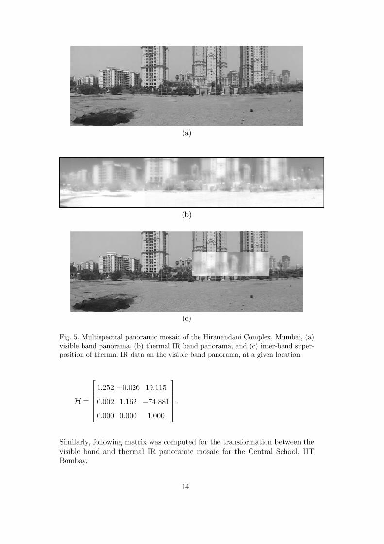
We took an arbitrary set of images of the Hiranandani Complex, Mumbai usinga panoramic set up. Figure 1 shows the experimental set up for capturingmultispectral images. To capture the images, a camcorder operating in thevisible band was mounted on a level tripod and we operate it in the manuallypre set mode where all the camcorder parameters such as aperture, shutterspeed, focal length were kept constant. Since the images are taken by panningthe camcorder in the scene, the rotation between the images is unknown andis not assumed to be constant. Figure 3 shows some images of the HiranandaniComplex, Mumbai, in the visible band. Next, images were captured using athermal IR camera (range 2 − 5µm) with the same set up. Figure 4 showssome images of the same scene in the thermal IR band. First we constructthe panoramic mosaic for both visible band and thermal IR images, usingour Geometric Hashing-based technique, as discussed above. We select, oneimage as reference image and all other images are transformed according theestimated transformation- they are stitched together to form a mosaic. Thenwe construct the panoramic mosaic in the thermal IR band. Figure 5 showsthe visible band and thermal IR panoramic mosaics; and an inter-band mosaicof the Hiranandani Complex, Mumbai, describing an approximately 240◦ fieldof view.
Figures 6 and 7 show some images of the Central School, IIT Bombay, in thevisible band and thermal IR band, respectively. Figure 8 shows similar resultsfor the school building. In both cases, we perform multispectral registrationin an interactive, semi-automatic manner. Here, some points of interest pointsare selected in both the thermal IR, and visible band mosaics. By finding thecorrespondence between the two mosaics, we estimate the required transfor-mation (Section 2.1) in a least-squares sense. The computed matrix showingthe transformation between the visible band and thermal IR band mosaic forthe case of the Hiranandani Complex is
13
(a)
(b)
(c)
Fig. 5. Multispectral panoramic mosaic of the Hiranandani Complex, Mumbai, (a)visible band panorama, (b) thermal IR band panorama, and (c) inter-band super-position of thermal IR data on the visible band panorama, at a given location.
H =
1.252 −0.026 19.115
0.002 1.162 −74.881
0.000 0.000 1.000
.
Similarly, following matrix was computed for the transformation between thevisible band and thermal IR panoramic mosaic for the Central School, IITBombay.
14

Fig. 6. Some images of a video sequence of the Central School, IIT Bombay in thevisible band.
Fig. 7. Some images of the Central School, IIT Bombay in the thermal IR band.
H =
1.332 −0.023 −25.849
0.003 1.158 −81.388
0.000 0.000 1.000
.
Once the thermal IR mosaic and visible band mosaic are registered throughthe transformation, they are combined to form a multispectral mosaic. In ourinteractive system, any part of interest from the thermal IR mosaic can beobtained by just clicking on points in the visible band mosaic, and vice versa.
15

(a)
(b)
(c)
Fig. 8. Multispectral panoramic mosaic of the Central School, IIT Bombay, servesas another example. (a) visible band panorama, (b) thermal IR band panorama,and (c) inter-band super-position of thermal IR data on the visible band panorama,at a given location.
Hence, we get the multispectral information about the scene.
6 Conclusion
We develop a method for multispectral image mosaicing, which gives informa-tion about different aspects of the scene, which is not possible with a singlecamera. The registered multi-sensor images can be fused at the pixel leveland subsequent operations can be carried out. This not only saves computa-
16

tions, it increases accuracy because the subsequent operations benefits fromthe spectral and geometric differences brought out by the fusion operation. Weachieve the goal by using simple sensors instead of using a complicated andcostly sensor. Our future research will include processing of the multispectralmosaics for feature classification and scene understanding purposes.
References
[1] Y. Schechner, S. Nayar, Generalized Mosaicing: Wide Field of ViewMultispectral Imaging, IEEE Transactions on Pattern Analysis and MachineIntelligence 24 (10) (2002) 1334 – 1349.
[2] J. Wellman, Multispectral Mapper: Imaging Spectroscopy as Applied to theMapping of Earth Resources, in: Proc. SPIE Imaging Spectroscopy, Vol. 268,1981, pp. 64 – 73.
[3] L. Rignot, R. Kowk, J. Curlander, S. Pang, Automated MultisensorRegistration: Requirements and Techniques, Photogrammetric Engineering andRemote Sensing 57 (8) (1991) 1029 – 1038.
[4] L. Hui, B. Manjunath, A Contour Based Approch to Multisensor ImageRegistration, IEEE Transactions on Image Processing 4 (3) (1995) 320 – 334.
[5] L. Hui, Automatic Visual/IR Image Registration, Optical Engineering 35 (2)(1996) 395 – 400.
[6] P. Dani, S. Chaudhuri, Automated Assembly of Images: Image MontagePreparation, Pattern Recognition 28 (3) (1995) 431 – 445.
[7] R. Szeliski, H. Yeung, Creating Full View Panoramic Image Mosaic andEnvironment Maps, in: Computer Graphics Proceedings, Annual ConferenceSeries, 1991, pp. 251 – 258.
[8] S. Peleg, B. Rousso, Universal Mosaicing Using Pipe Projection, in: Proc. IEEEInternational Conference on Image Processing (ICIP), 1998, pp. 123 – 132.
[9] L. Brown, A Survey of Image Registration Techniques, ACM ComputingSurveys 4 (1992) 325 – 376.
[10] R. Hartley, A. Zisserman, Multiple View Geometry in Computer Vision,Cambridge University Press, 2000.
[11] R. Pollefeys, R. Koch, L. Van Gool, Self-Calibration and Metric ReconstructionInspite of Varying and Unknown Intrinsic Camera Parameters, Int. Journal ofComputer Vision 32 (1) (1999) 7 – 25.
[12] I. Zoghlami, R. Deriche, Using Geometric Corners to Build a 2-D Mosaic froma Set of Images, in: Proc. IEEE International Conference on Image Processing(ICIP), 1997, pp. 420 – 425.
17

[13] U. Bhosle, S. Chaudhuri, S. Dutta Roy, A Fast Method For Image MosaicingUsing Geometric Hashing, IETE Journal of Research: Special Issue On VisualMedia Processing (2002) 317 – 324.
[14] U. Bhosle, S. Chaudhuri, S. Dutta Roy, Background Mosaicing of Scene WithMoving Objects, in: Proc. National Conference of Communication (NCC), 2003,pp. 84 – 89.
[15] C. Rothwell, Recognition using Projective Invariance, Ph.D. thesis, Universityof Oxford (1993).
18