multifunctional polymer coatings via - deep blue
TRANSCRIPT
MULTIFUNCTIONAL POLYMER COATINGS VIA CHEMICAL VAPOR DEPOSITION COPOLYMERIZATION
by
Yaseen Mohamed Elkasabi
A dissertation submitted in partial fulfillment of the requirements for the degree of
Doctor of Philosophy (Chemical Engineering)
in The University of Michigan 2009
Doctoral Committee: Associate Professor Joerg Lahann, Chair Professor Erdogan Gulari Professor Nicholas Kotov Assistant Professor Matthew R. Chapman

Then tell Me about the seed that you sow in the ground. Is it you that make it grow, or are We the grower? Were it Our will, We could crumble it to dry pieces, and you would lament: “We are indeed ruined!” “Nay, but we are deprived!” Then tell Me about the water that you drink. Is it you who send it down from the rain clouds, or are We the sender? If We willed, We verily could make it salty: why then do you not give thanks? Then tell Me about the fire which you kindle. Is it you that produce the trees for it, or are We the producer? We have made it a reminder, and an article of use for the travelers Then glorify with praises the name of your Lord, the Most Great.
– The Noble Quran, 56:63-74

ACKNOWLEDGEMENTS
All praises are due to my lord Allah, for any good that comes out of this work. I
praise Him, glorify Him, and seek His forgiveness.
This work would not be possible without the help and inspiration of many
talented people. First, I am indebted to my advisor, Joerg Lahann, for granting me the
opportunity to conduct ground-breaking research in a nurturing environment. He has
taught me much more than mere experimental work. I’ve learned how to play the game,
how to think of million-dollar ideas, and to aspire towards the best of what I can do. I’m
also grateful to my committee members Matthew Chapman, Erdogan Gulari, and
Nicholas Kotov, who have taken their time to guide me over the course of my Ph.D. My
collaborators have also given me much opportunity to branch my skills out into different
areas: Matthew Chapman, Dan Smith, Soon-Gong Choi, Daryl Kipke, John Seymour,
Paul Krebsbach, Wei-Wen Hu.
I also would like to thank the many lab mates I’ve had over the past several years.
In particular, Hsien-Yeh Chen was instrumental in teaching me what knowledge I have of
chemical vapor deposition. He also got me up and on my feet as a researcher. Himabindu
Nandivada, David Peng, Kyung-Ho Roh, and Mutsumi Yoshida also played integral roles
in training me. I thank you all for your patience and diligence in working with me. Your
down-to-earth attitudes have helped me to hold strong in a competitive field.
ii

Lidija Bondarenko, Gemma Galvan, Xuwei Jiang, and Aiwu Sun taught me valuable
lessons in organic synthesis, and those methods are quite useful to this day. Other lab
members provided an enthusiastic atmosphere geared towards research: Allen Ahmadi,
David Alberts, Srijanani Bhaskar, Allison Bourke, Tom Eyster, Sonsoles Olano, Xiaopei
Deng, Abbass Kazemi, Joseph Lai, Mark Lopez, Agusti Llorens, Aftin Ross, Sridhar
Valluri, Jason Wu, Jaewon Yoon.
A significant portion of my personal support was funded by the National Institute
of Biomedical Imaging and Bioengineering, as part of an NIH Training Grant. I have also
greatly benefited from the staff and graduate students in the Department of Chemical
Engineering at Michigan, as well as the Electron Microbeam Analysis Laboratory
(EMAL). Many thanks are due to all of you. I also thank professor Gulari and his lab
members for use of the fluorescence scanner, as it was an integral part of my work.
I have made many friends over the past 5 years, both within the department and
outside, who have given me moral support when I needed it: Amir Haji, Tabish Maqbool,
Dr. Kayghobad Shams, as well as many close friends at the Muslim Community
Association of Ann Arbor.
Last but definitely not least, my family: I love you all very much. Mama and
Baba, Randa, Heba, Mona, Mohammed, Rafik, and my wife Ala – without your moral
and financial support, I could not have become the person that I am today, let alone
accomplish this major milestone. Thanks for keeping my head down-to-earth all this
time.
iii

TABLE OF CONTENTS
ACKNOWLEDGEMENTS …………………………………………………………....…ii
LIST OF FIGURES ……………………………………………………………………..vii
LIST OF SCHEMES ………………………………………………………………...….xii
LIST OF TABLES ...…………………………………………………………………...xiii
LIST OF APPENDICES ………………………………………………………………..xiv
ABSTRACT …………………………………………………………………………......xv
CHAPTER 1 INTRODUCTION………………………………………………………. 1
1.1 Surface Modification Techniques ……..……………………………………...1
1.2 Chemical Vapor Deposition Polymerization ……..………..…………………3
1.3 Modification of CVD Polymer Coatings ……..……………...……………….7
1.3.1 Microcontact Printing …………………………………...………....7
1.3.2 CVD within Confined Microgeometries ………………......….….10
1.3.3 Vapor-Assisted Micropatterning in Replica Structures ...….......…12
1.3.4 Projection Lithography of Photoreactive CVD Polymers …..........16
1.3.5 Selective CVD on Metals ……………………………………...…19
1.4 Hypothesis and Specific Aims ……..………………………………………..22
1.5 Overview ……..……………………………………………………………...23
References ……………………………………………………………………….24
CHAPTER 2 MULTIFUNCTIONAL HOMOPOLYMER COATINGS …………. 31
2.1 Background and Motivations ……………….……………………………….31
2.2 Experimental Methods ………….…………………………………………...33
2.3 Results and Discussion ………………………………………………….......37
iv

2.3.1 Precursor Synthesis and Characterization ……………...…………37
2.3.2 CVD Polymerization and Characterization ……………………….38
2.3.3 Surface Modification ……………………………………………...45
2.3.4 Combination of Superhydrophobicity and Reactivity …………….46
2.4 Conclusions ………………………………………………………………….48
References ……………………………………………………………………….49
CHAPTER 3 MULTIPOTENT COPOLYMER COATINGS ……………………...51
3.1 Background and Motivations ………………………………………………..51
3.2 Experimental Methods ………….…………………………………………...52
3.3 Results and Discussion ……………………………………………………...55
3.3.1 CVD Copolymerization …………………………………………...55
3.3.2 Surface Reactions ………...………………….…………....……….65
3.4 Conclusions ………………………………………………………………….67
References ……………………………………………………………………….69
CHAPTER 4 PRELIMINARY BIOCOMPATIBILITY OF COPOLYMER
COATINGS …………………………………………………………………………….71
4.1 Background and Motivations ………………………………………………..71
4.2 Experimental Methods ………………………………………………………72
4.3 Results and Discussion ……………………………………………………...78
4.3.1 Mono-Functionalized CVD Coatings ……………………………..78
4.3.2 Multi-Functionalized CVD Coatings ……...………………………84
4.3.3 Biocompatibility Studies …………………………………………..90
4.3.4 Reactivity Study …………………………………………………...93
4.4 Conclusions ………………………………………………………………….96
References ……………………………………………………………………….98
CHAPTER 5 POLYMER COATINGS WITH REACTIVE SURFACE
COMPOSITION GRADIENTS …………………………………………………..…101
5.1 Background and Motivations …………………………………………….101
v
5.2 Experimental Methods ……………………………………………………..103
5.3 Results and Discussion …………………………………………………….106
5.3.1 Polymer Gradient Deposition ……………………………………106
5.3.2 Surface Reactions ………………………………………………...115
5.4 Conclusions ………………………………………………………………...116
References …………………………………………………………………...…118
CHAPTER 6 CONCLUSIONS ……………………………………………………... 121
6.1 Summary …………………………………………………………………...121
6.2 Future Directions and Potential Applications ……………………….……..122
6.2.1 Superhydrophobic Reactive Coatings …….……………………..122
6.2.2 Multipotent Copolymer Coatings ..…….………………………...125
6.2.3 CVD Copolymer Gradients ………………………...……………127
References ……………………………………………………………………...129
APPENDICES ……………………………………………………………………..….130
vi

LIST OF FIGURES
Figure 1.1. Functionalized [2.2]paracyclophanes (PCPs) can be polymerized into functionalized poly(p-xylylenes) (PPXs) with tailored reactivity. Taken from [64] ……..3 Figure 1.2. Two general protocols for fabrication of micropatterned surfaces are described. 1) CVD process, followed by subsequent patterning of the reactive coating. 2) Patterned deposition of the CVD polymer ……………………………………………..…6 Figure 1.3. Microcontact printing process for (a) the immobilization of sugars onto aldehyde-functionalized PPX and (b) click chemistry. Taken from [69] and [73] ……….8 Figure 1.4. Conformal deposition of CVD polymers occurs even within microscale geometries. Facile modification and biofunctionalization of microfluidic channels can be attained. Adapted from [75]. ……..…………………….………………………………..11 Figure 1.5. (a) Process of vapor-assisted microstructuring using replica structures (left column) as well as shadow masks (right column) during CVD polymerization. Fluorescently-tagged molecules are immobilized onto (b) poly(4-pentafluoropropionyl-p-xylylene-co-p-xylylene) and (c) poly(p-xylylene-4-methyl-2-bromoisobutyrate-co-p-xylylene). The latter was used to grow poly(OEGMA) within the squares, which inhibited the adsorption of fibrinogen (i) and attachment of NIH 3T3 fibroblasts (ii). Adapted from [79] and [81] …………………………………………………….....………….…..…….14 Figure 1.6. Plot of dimensionless thicknesses δ(x)/δ0 vs. dimensionless width (x/b), where δ0 is film thickness (nm) on an open area for an according dimension recorded by using imaging ellipsometry; b is the width (µm) of the dimension. Taken from [79] .….15 Figure 1.7. Schematic description of the 3D projection lithography technique. The method comprises two process steps: deposition of the photodefinable CVD coating (step 1) and subsequent projection lithographic rendering of the polymer-coated colloids (step 2). Inset shows an endovascular stent and a microfluidic pathway that are patterned using projection lithography. Adapted from [84] and [85] .………………………………...…17 Figure 1.8. (a) Schematic illustration of the selective deposition of poly(4-vinyl-p-xylylene-co-p-xylylene) on patterned Ti/Au substrates. Au was deposited through a shadow mask onto a Ti-coated silicon wafer followed by polymer deposition via CVD polymerization. Olefin cross-metathesis reaction of fluorescein O-methacrylate was used to probe the selective deposited polymer on Au surface. (b) Fluorescence micrograph
vii

reveals that only the Au islands showed appreciable signals of fluorescence. Taken from [97] ………………………………………………………………………………………21 Figure 2.1. Grazing angle FTIR spectrum of polymer 2 deposited on a gold substrate ..39
Figure 2.2: XPS survey spectrum of polymer 2; inset shows the high-resolution C1s spectrum …………………………………………………………………………...…….40 Figure 2.3: FTIR spectrum of polymer 4 deposited on a gold surface …………………41 Figure 2.4: XPS survey spectrum of polymer 4; inset shows the high-resolution C1s spectrum …………………………………………………………………………………42 Figure 2.5: Comparing contact angles of non-functionalized PPX, polymer 2, PPX-COCF3, PPX-COC2F5 and polymer 4 …………………………………………………...43 Figure 2.6: Adhesion tests of (a) polymer 2 and (b) polymer 4. The polymer surface was first marked using a sharp object and then scotch tape was pressed onto the surface. The surface was observed before and after peeling off the tape. Optical micrographs before and after testing are shown on the left and right panels, respectively. IR spectra remained identical before and after testing ………………………………………………………...44 Figure 2.7: (a) Schematic of the microcontact printing process used to verify the reactivity of polymer 4 towards hydrazides. (b) Fluorescence micrographs of TRITC-labeled streptavidin immobilized onto patterned biotin hydrazide substrates ………..…46 Figure 2.8: SEM of the surface (a) before CVD coating (b) after CVD coating. Insets show the corresponding water contact angles. (c) Confocal image showing binding of fluorescently-labeled streptavidin to biotinylated, micropatterned surfaces ……………47 Figure 3.1. The multifunctional polymer (3) accessible by CVD copolymerization of [2.2]paracyclophanes (1) and (2); the structures of the individual polymers 4 and 5 are shown for comparison ……………………………………………………………..…….55 Figure 3.2 – XPS elemental imaging maps of (a) fluorine and (b) nitrogen, for copolymer 3 prepared with a 1:1 feed ratio ………………………………………………………... 56 Figure 3.3 Graph of copolymer ratios of CH2NH2:COCF3 plotted against their monomer loading ratios …………………………………………………………….………………58 Figure 3.4. FTIR spectra of (3) with varying molar ratios of CH2NH2:COCF3. (a) pure CH2NH2 (b) 5:1 (c) 2:1 (d) 1:1 (e) 1:2 (f) 1:5 (g) pure COCF3 …………………………60 Figure 3.5 (a) Schematic representation of substrate positions arranged on the CVD sample holder. (b) Plot of FTIR peak ratios (CN:C=O), with respect to substrate temperature ……………………………………………………………………………...62
viii

Figure 3.6. X-ray diffraction patterns of the individual polymers 4 and 5 and the copolymer 3 (a) before and (b) after annealing at 120 oC. Only the polymer 4 exhibits crystallinity after annealing. (c) X-ray diffraction of copolymers with varying ratios. (d) X-ray diffraction of 4 at various annealing temperatures ……………………………….64 Figure 3.7. Schematic outlining the selective reactivity of the multivalent surface. The activated ester will only react with the aminomethyl group, while the hydrazide group shows selective reactivity towards ketones ……………………………………………...65 Figure 3.8. Fluorescence intensities detected on the co-polymers versus x(2), the relative feed concentration of [2.2]paracyclophane 2 used for CVD copolymerization. The trends demonstrate ligand immobilization occurs in controlled ratios as a function of increasing relative ratio of the [2.2]paracyclophanes. Inlet: Fluorescence micrograph of areas that were reacted with biotin ligand (1), Atto 655 ligand (2), or both (3) …………………...66 Figure 4.1 FTIR spectra of PPX polymers containing the following functional modifications: (a) COC6H5, (b) COC2H5,(c) COC2F5, and (d) COCF3 ………………....81 Figure 4.2 XRD of carbonyl-functionalized polymers upon annealing at 120°C for 14 hours ……………………………………………………………………………………..82 Figure 4.3 Confocal microscopy images of HUVECs grown on (a) poly(L-lysine) coated cover slip, (b) PPX-CH2NH2, (c) PPX-NH2, (d) PPX-COC6H5, (e) PPX-COC2H5, (f) PPX-COC2F5, and (g) PPX-COCF3 surfaces. Red: actin cytoskeleton (rhodamine-phalloidin), blue: nucleus (DAPI). n=3, representative images shown. All scale bars are 50 µm …………………………………………………………………………………....83 Figure 4.4 FTIR spectra of CVD copolymer (-NH2/-COC2F5), copolymerized in different molar ratios of PPX-NH2: PPX-COC2F5. (a) pure PPX-NH2 (b) 5:1 (c) 2:1 (d) 1:1 (e) 1:2 (f) 1:5 (g) pure PPX-COC2F5 ……………………………………..................…………..86 Figure 4.5 FTIR spectra of CVD copolymer (-CH2NH2/-COC2H5) copolymerized to different molar ratios of PPX-CH2NH2: PPX-COC2F5. (a) pure PPX-CH2NH2 (b) 5:1 (c) 2:1 (d) 1:1 (e) 1:2 (f) 1:5 (g) pure PPX-COC2H5 ..............................................................87 Figure 4.6 Fibrinogen adsorption on various substrates. Normalized fluorescence values are reported. Results were compared to TCPS. n=3, *: p<0.05 …………………………90 Figure 4.7 G6PD release from NIH 3T3s grown on various substrates. Fluorescence values are reported. Results are compared G6PD measured in media supporting live cells. n=3, *: p<0.05 …………………………………………………………………….91 Figure 4.8 Confocal microscopy images of NIH 3T3 murine fibroblasts grown on (a) poly(L-lysine) coated cover slip, (b) polyvinyl chloride film, (c) PPX-CH2NH2, (d) 1:1 ratio of PPX-CH2NH2 and PPX-COCF3, (e) PPX-COCF3 surfaces. Red: actin
ix

cytoskeleton (rhodamine-phalloidin), blue: nucleus (DAPI). n=3, representative images shown. All scale bars are 50 µm ………………………………………………………..92 Figure 4.9 (a) Protocol used to determine the reaction kinetics of different carbonyl-PPXs, using functionalized p-xylenes as test molecules. (b) Percent yield of carbonyl reactions with respect to time, based upon 1H NMR of characteristic reactant/product peaks …………………………………………………………………………………….94 Figure 4.10 (a) Hirudin binding as measured by chromogenic assay. Normalized absorbance at 405 nm are reported. n=3, *: p<0.05 compared to stainless steel. (b) Heparin binding as measured by Toluidine Blue absorbance. Normalized absorbance at 631 nm are reported. n=3, *: p<0.05 compared to stainless steel ………………………96 Figure 5.1. A side-view schematic of the custom-built two-source CVD system. Each source consists of a quartz tube that passes through a 3-zone furnace and then connects into the deposition chamber. Both the tubes and the chamber together are held at 0.16 Torr. (1) and (2) sublimate, undergo pyrolysis, and then copolymerize to deposit on the sample holder. The specified process conditions create a poly(p-xylylene) (PPX) film possessing a functional composition gradient …………………………………….……107 Figure 5.2. (a) Side view of the CVD sample holder. AB = BC = 7.6 cm. AC = 15.2 cm. (b) FTIR spectra of CVD copolymers produced from the conditions of scheme 1. The bulk ratio of CVD copolymer changes with respect to position along the sample holder …………………………………………………………………………………………..109 Figure 5.3. FTIR spectra of CVD copolymer gradients, using condition 2 …………...110 Figure 5.4. Copolymer compositions along the surface gradient, based upon XPS survey spectra. Copolymer ratios are calculated based upon the percentage of fluorine and nitrogen, both characteristic of (1) and (2), respectively. The concentration of aminomethyl groups increases with respect to position along the substrate. The compositional rate of change can be controlled by manipulating argon flow rates and sublimation rates ……………………………………………………………………….112 Figure 5.5. (a) Schematic of the biomolecular immobilization process (b) Fluorescence image and (c) intensity profiles of immobilized fluorescent dyes across a CVD polymer gradient. Both Atto 655 NHS ester (red) and biotin hydrazide with rhodamine-tagged streptavidin (green) reacted over the same regions, showing that the composition gradient can be converted into immobilization gradients ……………………………………….115 Figure 6.1 Preliminary experimental protocols for (a) contact angle gradient fabrication and (b) screening gradient surfaces for non-fouling characteristics. …………………..124 Figure 6.2 Procedure for fabrication of copolymer surface potentially bearing 8-10 functional groups ………………………………………………………………………125
x

Figure 6.3 Overhead-view schematic of a potential three-source CVD system ……....128
xi
LIST OF SCHEMES
Scheme 2.1: Mechanism of CVD polymerization of partially fluorinated [2.2]paracyclophanes to yield the corresponding poly-p-xylylenes. Polymer 2 is fluorinated at the aliphatic bridge, whereas polymer 4 contains a fluorinated reactive group at the aromatic ring ……………………………………………………………….32 Scheme 4.1. (a) Mechanism for the CVD polymerization of carbonyl-functionalized PCPs to produce corresponding PPXs. (b) Schematic diagram of CVD process. (c) CVD process conditions required for PPX deposition ………………………………………...79 Scheme 4.2 Mechanism for CVD copolymerization of two different PCPs ….………...85
xii

LIST OF TABLES
Table 2.1: High resolution C1s XPS data for polymers 2 and 4 ………………………...40 Table 3.1. High-resolution C1s XPS results for poly[(4-aminomethyl-p-xylylene)-co-(4-trifluoroacetyl-p-xylylene)-co-p-xylylene] (3) prepared with a 1:1 feed ratio compared to the individual polymers 4 and 5 …………………………………………………………57 Table 3.2. XPS composition of copolymer (PPX-CH2NH2/-COCF3), deposited using various monomer sublimation temperatures. Monomer loading ratio of 1:1 was used for all depositions …………………………………………………………………………...59 Table 4.1. Elemental compositions of CVD copolymers containing 1:1 ratios of (a) (PPX-NH2):(PPX-R) (b) (PPX-CH2NH2):(PPX-R), as determined by XPS. Atomic composition results are shown on the top half of each table, while high resolution C1s spectra results are shown on the bottom. Theoretical calculations are based upon ideal deposition of the copolymer ratio …………………………………….…………………89
xiii
LIST OF APPENDICES Appendix A: Protocol for Escherichia coli Adhesion onto Poly(p-xylylene) Coated Surfaces …………………………………………………………………………..….…131 Appendix B: Escherichia coli Adhesion Experiments on Poly(p-xylylenes) ……..…..133
xiv

ABSTRACT
The dissertation investigates how reactive polymer coatings can facilitate
controlled immobilization of multiple biomolecules and can control multiple surface
properties independently for biomedical applications. Chemical vapor deposition (CVD)
copolymerization technology was chosen for the surface modification of substrates and
biological devices, due to its high degree of conformal deposition. This feature was
evidenced by the conformal deposition of reactive coatings within pre-assembled
microfluidic channels, with aspect ratios as high as 37.
A superhydrophobic reactive CVD-coated surface was designed. The coating can
immobilize proteins, despite its extremely high contact angle (> 155o). Also, multipotent
copolymer coatings presenting two different biological ligands in controllable ratios were
prepared via CVD copolymerization of two functionalized PCPs. These polymer coatings
are designed so that different reactive groups can be orthogonally introduced, making
them attractive for a wide range of biomedical devices.
Preliminary biocompatibility of these coatings was assessed in short-term
experiments (24-48 hr), using human umbilical vein endothelial cells and 3T3 murine
fibroblasts. Both cell types adhered and spread on PPX polymers, with limited growth
occurring on fluorinated PPX coatings. G6PD assays indicated significantly low
cytotoxicity of CVD surfaces, when cultured with fibroblasts. We also demonstrate the
immobilization of two different antithrombotic biomolecules onto a CVD-based
xv

copolymer via orthogonal immobilization strategies. The antithrombotic biomolecules
retained their bioactivity after immobilization. Furthermore, a modified CVD process was
used to produce coatings which possess reactive surface composition gradients. The as-
deposited gradient compositions range from 85% to 20%. Also, the CVD system can
deposit various gradient slopes, such that the same composition range is deposited over
distances of 1’’, 3’’, or 6’’. These surface gradients can immobilize two biomolecules as
gradients, allowing for further adaptation to specific biological environments.
Applications from this dissertation include the development of novel analytical
biodevices, tissue engineering protocols, and combinatorial screening platforms. For
instance, growth and differentiation of neurons occur along a chemical gradient. CVD
copolymer gradients could mimic biological environments to guide their growth. Also,
gradient deposition allows for the mass production of many copolymer compositions in
one deposition. These samples could then be simultaneously screened for their
interactions with cells.
xvi
1
CHAPTER 1
INTRODUCTION
The materials in this chapter have been adapted with minor modifications from
the following book chapter: Y. Elkasabi, J. Lahann, “Recent Progress in Microstructured
Surfaces Based on Chemical Vapor Deposition Methods”, Biological Microarrays:
Methods in Molecular Biology Series, Humana Press (in press).
1.1 Surface Modification Techniques
Controlled surface engineering has been a long-standing challenge in the
development of bioarrays, artificial implants, and biomedical devices. Moreover,
miniaturized diagnostic systems, such as micro-total analysis systems (µTAS),[1] cell-
based assays,[2] microseparators for proteins,[3,4] DNA,[5] and polysaccharides,[6] often
require universally applicable surface engineering protocols. Some general surface
modification techniques have proven to be versatile in alleviating adverse biological
effects. One technique that is widely used to tailor the interfacial properties of metals,
metal oxides and semiconductor surfaces is the use of self-assembled monolayers
(SAMs).[7] Based on the terminal functional groups exposed on the surface of a SAM, the
surface reactivity can be varied. SAMs have been used for the direct immobilization of
DNA, polypeptides and proteins.[8] However the use of SAMs is limited due to the
relative chemical instability of the monolayer and the specificity of the substrates. In
contrast, the above-mentioned applications require robust surface chemistry.

2
Extensive efforts have been made to create topological surface modifications
using printing methods, such as dip/pen lithography,[9] patterning via scanning probes,[10]
imprinting lithographies,[11,12] or soft lithography.[13,14] Included within soft lithography
are: micromoulding in capillaries,[15] microcontact printing,[16] replica moulding,[17]
microtransfer moulding,[18] solvent-assisted micromoulding,[19] and capillary force
lithography.[20] Soft lithographical methods rely on the use of elastomeric stamps or
replica structures to transfer material from a solution onto a surface. Patterned substrates
created using shadow masks included a range of different materials, such as
semiconductors,[21-23] organic metals,[24] polymers,[25] biomaterials[26] or cells.[27-29]
Surface patterns have also been fabricated using lithographical techniques, on the basis of
light,[30] X-rays,[31] electron[32] and ion beams,[33] or atoms[34].
Furthermore, patterned substrates can be incorporated into microfluidic systems
subsequently used for high-throughput proteomics applications, pharmaceutical screening
of cellular assays, or cell-based biosensors. Methods for creating patterns in microfluidic
channels previously depended on patterning of a flat substrate, which is then sealed to the
microchannel. Some specific processes utilize microfluidic patterning,[35] laminar flow
patterning,[36-38] robotic spotting,[39-41] and jet printing,[42,43] and selective plasma
etching.[44] These patterning methods have been used to pattern hydrogels[45-47],
cells,[48,49] and proteins[36] within microfluidic systems. However, they often have several
shortcomings. For example, patterns generated by laminar flow patterning and
microfluidic patterning are limited to a relatively narrow range of continuous patterns,
which are mainly determined by the flow geometry.
3
1.2 Chemical Vapor Deposition Polymerization
In addition to solvent-based methods that are being utilized for biomedical surface
modification, solventless surface modification methods, such as chemical vapor
deposition (CVD) polymerization, are currently being explored for biomedical devices.
*m
n
Polymerization *
R4
R1
R2
R1
R2
R4R3
R3
O
H
NH2NH2
H2N
OH O O
O
O
O
O
O
O
O
O
O
O
O
O
O
OO
OO
OO
O
O
F
FF
F
F
O
O
CF3 OS
O
CF3O
O
O
Br
NH2
(a)
FurnaceSublimationzone
Depositionchamber + substrates
Monomerloading
P
T
(b)
(c)
*m
n
Polymerization *
R4
R1
R2
R1
R2
R4R3
R3
O
H
NH2NH2
H2N
OH O O
O
O
O
O
O
O
O
O
O
O
O
O
O
OO
OO
OO
O
O
F
FF
F
F
O
O
CF3 OS
O
CF3O
O
O
Br
NH2
(a)
FurnaceSublimationzone
Depositionchamber + substrates
Monomerloading
P
T
FurnaceSublimationzone
Depositionchamber + substrates
Monomerloading
P
T
(b)
(c)
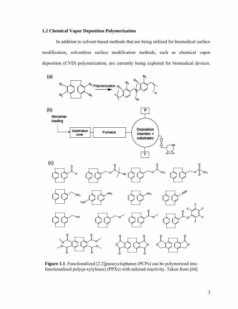
Figure 1.1. Functionalized [2.2]paracyclophanes (PCPs) can be polymerized into functionalized poly(p-xylylenes) (PPXs) with tailored reactivity. Taken from [64]

4
Many of the advantages to CVD polymerization are unique when compared to solvent-
based coating processes. First, impurities associated with the use of solvents, initiators, or
plasticizers are non-existent. Second, CVD coatings are conformal, allowing for simple
and uniform modification of three-dimensional substrate geometries.[50] Third, although
the initiation step requires high temperatures, initiation takes place away from the
substrate, and the substrates can be controlled and maintained at room temperature. The
control over substrate temperature allows for the deposition of polymers onto delicate
substrates, as well as onto mechanically strong materials made of inorganic substances.
Several examples of CVD-based polymer coatings have been reported: Frank and
coworkers[51,52] have grafted polypeptide chains onto a surface using CVD. Gleason and
coworkers[53,54] have shown that polymerization initiators can be introduced together with
the monomer through basic process modification, thus facilitating the polymerization of
monomers which do not contain an initiator. Hot filaments within the deposition chamber
can be used for initiation of radical polymerizations, which often yields conformal
coatings.
A major focus of CVD polymerization has been the polymerization of substituted
[2.2]paracyclophanes (PCP) to yield functionalized poly(p-xylylenes) (PPX). This CVD
polymerization is adapted from a process first developed by Gorham for parylene
coatings.[55] In this procedure (Figure 1.1), a cyclic dimer is sublimated under vacuum
(0.2-0.3 Torr), and transported by a carrier gas through an external heat source (T = 600 –
800 oC). If the temperature is sufficiently high, a homolytic cleavage occurs across both
bridge bonds, resulting in two quinodimethane diradicals, serving as an initiation step.
The radicals then deposit and polymerize onto a sample that is fixed at a particular

5
temperature. For deposition of PPX polymers, the substrate temperature is critical for
obtaining high-quality coatings. Generally, as substrate temperature decreases, the
thickness of the PPX coating increases accordingly.[56] However, under normal CVD
conditions for other materials, the substrate temperature and resulting film thickness are
directly proportional to each other.[57] Much work has been done to model the
mechanisms behind this trend.[56,58]
For a given substrate temperature, the pyrolyzed quinodimethane monomer will
adsorb onto the substrate at a given surface density. Adsorption is then followed by
spontaneous propagation reaction, resulting in growth of the polymer chain. At the same
time, monomers and/or oligomers can desorb back into the CVD atmosphere. Thus, the
rate of propagation is limited by the desorption rate. The fraction of adsorbed monomers
that undergo polymerization is referred to as the sticking coefficient.[59] As the substrate
temperature increases, the rate of monomer desorption increases, resulting in a lower
sticking coefficient. Propagation rates remain constant, so long as the CVD process
conditions remain at steady-state. This is because the rate of radical generation
(pyrolysis) equals the rate at which radicals are buried in the growing film.[56] The
termination of radical polymerization is dominated by coupling with ambient O2. Hence,
a contaminated CVD system can result in unstable, low molecular weight polymer films.
Typically, CVD polymers are deposited using substrate temperatures between -40
and 60 oC, where 60 oC represents the maximum temperature of significant PPX
deposition.[56] Temperatures below -40 are not practical for real applications, and such a
low temperature can damage delicate substrates. Room-temperature substrates facilitate
the deposition of robust PPX coatings at controlled thicknesses and deposition rates, and
6
Patterningpost-CVD
Selective deposition on metalsMicrocontact printing
Patterned deposition during CVD
(substrate)
Projection lithographyMicropatterning in replica structures
Patterningpost-CVD
Selective deposition on metalsMicrocontact printing
Patterned deposition during CVD
(substrate)
Projection lithographyMicropatterning in replica structures
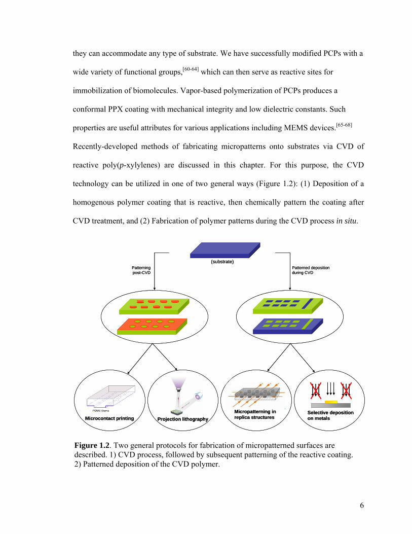
Figure 1.2. Two general protocols for fabrication of micropatterned surfaces are described. 1) CVD process, followed by subsequent patterning of the reactive coating. 2) Patterned deposition of the CVD polymer.
they can accommodate any type of substrate. We have successfully modified PCPs with a
wide variety of functional groups,[60-64] which can then serve as reactive sites for
immobilization of biomolecules. Vapor-based polymerization of PCPs produces a
conformal PPX coating with mechanical integrity and low dielectric constants. Such
properties are useful attributes for various applications including MEMS devices.[65-68]
Recently-developed methods of fabricating micropatterns onto substrates via CVD of
reactive poly(p-xylylenes) are discussed in this chapter. For this purpose, the CVD
technology can be utilized in one of two general ways (Figure 1.2): (1) Deposition of a
homogenous polymer coating that is reactive, then chemically pattern the coating after
CVD treatment, and (2) Fabrication of polymer patterns during the CVD process in situ.
7
1.3 Modification of CVD Polymer Coatings
1.3.1 Microcontact Printing
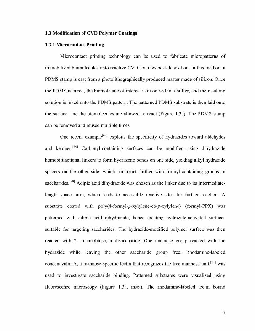
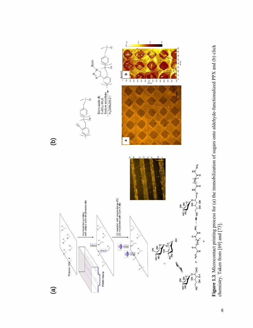
Microcontact printing technology can be used to fabricate micropatterns of
immobilized biomolecules onto reactive CVD coatings post-deposition. In this method, a
PDMS stamp is cast from a photolithographically produced master made of silicon. Once
the PDMS is cured, the biomolecule of interest is dissolved in a buffer, and the resulting
solution is inked onto the PDMS pattern. The patterned PDMS substrate is then laid onto
the surface, and the biomolecules are allowed to react (Figure 1.3a). The PDMS stamp
can be removed and reused multiple times.
One recent example[69] exploits the specificity of hydrazides toward aldehydes
and ketones.[70] Carbonyl-containing surfaces can be modified using dihydrazide
homobifunctional linkers to form hydrazone bonds on one side, yielding alkyl hydrazide
spacers on the other side, which can react further with formyl-containing groups in
saccharides.[70] Adipic acid dihydrazide was chosen as the linker due to its intermediate-
length spacer arm, which leads to accessible reactive sites for further reaction. A
substrate coated with poly(4-formyl-p-xylylene-co-p-xylylene) (formyl-PPX) was
patterned with adipic acid dihydrazide, hence creating hydrazide-activated surfaces
suitable for targeting saccharides. The hydrazide-modified polymer surface was then
reacted with 2—mannobiose, a disaccharide. One mannose group reacted with the
hydrazide while leaving the other saccharide group free. Rhodamine-labeled
concanavalin A, a mannose-specific lectin that recognizes the free mannose unit,[71] was
used to investigate saccharide binding. Patterned substrates were visualized using
fluorescence microscopy (Figure 1.3a, inset). The rhodamine-labeled lectin bound
8
(a)
(b)
(a)
(b)
Fi
gure
1.3
. Mic
roco
ntac
t prin
ting
proc
ess f
or (a
) the
imm
obili
zatio
n of
suga
rs o
nto
alde
hyde
-fun
ctio
naliz
ed P
PX a
nd (b
) clic
k ch
emis
try. T
aken
from
[69]
and
[73]
.
9
specifically to the disaccharide-presenting surface, which was then immobilized onto a
substrate coated with formyl-PPX and patterned with lines of adipic acid dihydrazide.
Immobilization of microscale patterns on formyl-PPX can also be extended towards
DNA immobilization.[72] Supermolecular nanostamping (SuNS) was used to fabricate
DNA nanopatterns immobilized onto formyl-PPX. The patterns can be lines or spots, an
important feature for the operation of DNA microarrays.
Another example[73] involved the use of poly(4-ethynyl-p-xylylene-co-p-xylylene)
(ethynyl-PPX), a polymer specifically tailored for use in click chemistry. Its reactivity
against azides was studied, in order to assess whether the coating can be used for
heterogeneous click reactions. Huisgen 1,3-dipolar cycloaddition between ethynyl-PPX
and an azide-containing biotin-based ligand in the presence of copper(II) sulfate and
sodium ascorbate was examined (Figure 1.3b). This coupling reaction yields triazoles, as
described for solvent-based systems.[74] Sodium ascorbate acts as a reductant, generating
CuI ions in situ, which then function as the catalyst.[74] Biotin azide (Photoprobe biotin,
Vector Labs) was chosen as the representative ligand in this study, because biotin forms a
strong noncovalent interaction with streptavidin (which has been widely used for binding
biotinylated biomolecules).[60]
A thin layer of biotin azide and sodium ascorbate was spread onto a film of
ethynyl-PPX and dried using N2. In comparison to the concurrent microcontact printing
of catalyst and azide, a two-step approach was found to be superior. A patterned PDMS
stamp was then inked with a CuSO4 solution and kept in contact with the substrate for 12-
18 h. The patterned substrate was rinsed and incubated with an aqueous solution of
rhodamine-labeled streptavidin. The immobilization of biotin azide onto ethynyl-PPX

10
was assed using fluorescence microscopy. The fluorescence micrograph and ellipsometric
thickness map shown in Figure 1.3b confirm selective protein coupling in the regions
where the CuSO4 solution was microcontact printed, thus demonstrating the spatially
directed binding of biotin azide to ethynyl-PPX. Thus, the alkyne groups on the polymer
surface are reactive and can be effectively used as anchoring sites for various
biomolecules.
1.3.2 CVD within Confined Microgeometries
Even though miniaturized bioanalytical devices contain dimensions of high aspect
ratios, the homogeneous modification of their surfaces can be challenging. In an attempt
to expand CVD polymerization to the coating of complex microgeometries with high
aspect ratios, a recent study[75] examined the deposition behavior of functionalized
poly(p-xylylenes) within preassembled microfluidic devices. It was demonstrated that
CVD polymerization can be used to deposit a range of functionalized poly(p-xylylenes)
within confined microgeometries.
Seven different poly(p-xylylenes) were deposited via CVD polymerization within
both removable and sealed PDMS microchannels.[76] A subgroup of five poly(p-
xylylenes) had reactive side groups (so-called reactive coatings), while two commercially
available poly(p-xylylenes) were included as nonfunctionalized references (ParyleneTM N
and C). The PDMS microchannels used in this study were open at both ends and were 75
µm high and 100 µm wide. Both straight (1600 m long) and meandering channel (2800 m
long) layouts with high aspect ratios were studied (Figure 1.4). For both straight and

11
meandering microchannels the degree of deposition was constant and did not change with
increasing film thickness. Homogenous surface coverage of different microgeometries
has been demonstrated for all reactive coatings. Deposition within aspect ratios of up to
37 was accomplished, based on optical microscopy and imaging XPS results.
In addition to the deposition studies, immobilization studies were conducted using
permanently sealed PDMS devices[76] after CVD polymerization. The microchannels
Figure 1.4. Conformal deposition of CVD polymers occurs even within microscale geometries. Facile modification and biofunctionalization of microfluidic channels can be attained. Adapted from [75].

12
were coated with either poly(4-amino-p-xylylene-co-p-xylylene) (amino-PPX) or poly(4-
trifluoroacetyl-p-xylylene-co-p-xylylene) (PPX-COCF3) prior to immobilization. While
amino-PPX provides primary amino groups for coupling with activated carboxyl groups
(amide formation), PPX-COCF3 has keto groups that can react with hydrazines or
hydrazides. To assess the chemical activity of both reactive coatings, a PFP-derived
biotin ligand and a biotin hydrazide ligand were used to evaluate chemical reactivity of
amino-PPX and PPX-COCF3, respectively. These ligands undergo nearly quantitative
conversion with amines or ketones; also, the interactions between biotin and streptavidin
result in tight confinement of streptavidin on the biotin-modified surface. For all ligand
immobilization reactions, aqueous solutions of the corresponding biotin derivative were
filled into the sealed microchannels of either meandering or straight geometry. After
thorough rinsing with buffer, microchannels were incubated with rhodamine-labeled
streptavidin, then the surfaces were rinsed and visualized by fluorescence microscopy.
Figure 1.4 shows microchannels that were coated with polymer and then subjected to the
biotin/strepdavidin protocol. Homogeneous distribution throughout the entire
microchannel was observed, indicating that functional groups were available throughout
the entire coating area, for both amino-PPX and PPX-COCF3. The deposition of reactive
CVD coatings within confined microgeometries bridges a critical technological gap
toward surface-modified microfluidic devices for use in "BioMEMS" applications.
1.3.3 Vapor-Assisted Micropatterning in Replica Structures
A related patterning approach utilizes vapor-assisted micropatterning in replica
structures (VAMPIR). In this method, chemical and topological surface microstructures

13
can be obtained by masking certain areas of the substrate during chemical vapor
deposition polymerization and then depositing the reactive coatings only within the
exposed areas. Although conceptually simple, such an approach towards microstructured
surfaces came with some challenges. For instance, in CVD polymerization, polymer
deposition is transport-limited, and the feasibility of deposition within replica structures
with micron-scale capillaries was unclear. However, the properties of polymers deposited
are of a greater variety. While stencils and shadow masks have been applied for area-
selective deposition using both rigid and elastomeric materials,[24, 77, 78] many of those
pattern processes are limited to hydrophilic polymers that are soluble in polar solvents.
However, the solvent-free process described here can be used for both hydrophilic and
hydrophobic coatings.
In a recent study,[79] polydimethylsiloxane (PDMS) based replica structures (or
stencils) designed to generate a desired surface pattern were reversibly sealed onto a
silicon substrate (Figure 1.5). The masked substrate was then placed onto a temperature-
controlled stage (15 ºC) inside of the CVD polymerization chamber. 4-
pentafluoropropionyl[2.2]paracyclophane underwent pyrolysis and polymerized into
poly(4-pentafluoropropionyl-p-xylylene-co-p-xylylene). After completion of the CVD
polymerization, the PDMS molds were removed, and hence a chemically and
topologically structured surface was created. Surface features are defined by the
deposited polymer footprints. In one instance, a substrate was masked with a PDMS
membrane, which contained footprints shaped into the letters “UM” (Figure 1.5b).
Subsequent CVD polymerization resulted in ultra-thin polymer films outside of the
masked areas. Imaging X-ray photoelectron spectroscopy confirmed the presence of

14
characteristic elements within their localized regions – i.e., fluorine was found only
outside the “UM” footprint boundaries, whereas silicon was found within the footprint.
PPX-COC2F5 has keto groups that can react with hydrazines or hydrazides in high
yields.[80] Biotin hydrazide, a model ligand, was used for immobilization onto the
functionalized polymer. In a subsequent step, the well-known interactions between biotin
(a)
(b) (c) i ii
(a)
(b) (c) i ii
Figure 1.5. (a) Process of vapor-assisted microstructuring using replica structures (left column) as well as shadow masks (right column) during CVD polymerization. Fluorescently-tagged molecules are immobilized onto (b) poly(4-pentafluoropropionyl-p-xylylene-co-p-xylylene) and (c) poly(p-xylylene-4-methyl-2-bromoisobutyrate-co-p-xylylene). The latter was used to grow poly(OEGMA) within the squares, which inhibited the adsorption of fibrinogen (i) and attachment of NIH 3T3 fibroblasts (ii). Adapted from [79] and [81].
15
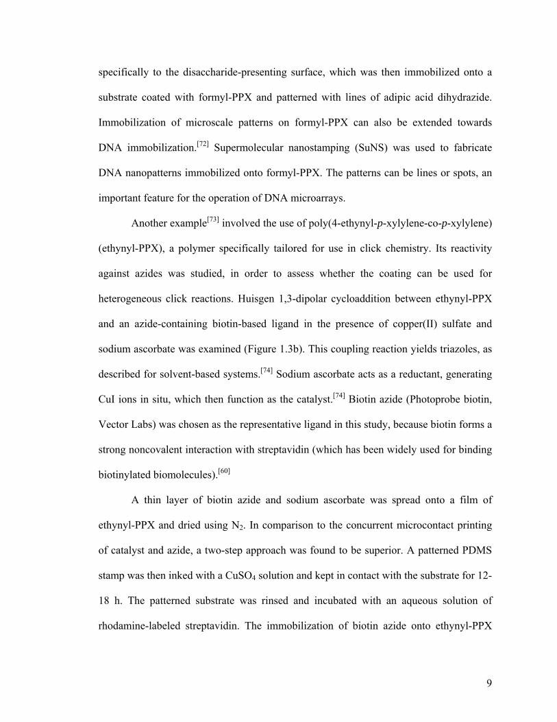
Figure 1.6. Plot of dimensionless thicknesses δ(x)/δ0 vs. dimensionless width (x/b), where δ0 is film thickness (nm) on an open area for an according dimension recorded by using imaging ellipsometry; b is the width (µm) of the dimension. Taken from [79].
and streptavidin are used for visualization of surface-immobilized biotin. To examine the
immobilization of biotin ligands within the patterns, streptavidin conjugated with CdSe
quantum dots (Qdot® 525) were allowed to bind to the biotin-modified surfaces. Binding
was homogenous throughout the surface-modified areas. As anticipated, after biotin
immobilization, the subsequently self-assembled quantum dots were resolved into a range
of different pre-designed patterns.
In another instance,[81] poly(p-xylylene-4-methyl-2-bromoisobutyrate-co-p-
xylylene) was patterned in the same manner as described for PPX-COC2F5. A PDMS
structure with square holes was used during the deposition process. After patterned
deposition of poly(p-xylylene-4-methyl-2-bromoisobutyrate-co-p-xylylene) onto PMMA
surfaces (Figure 1.5c), the initiator contained within the functionalized coating was used
to perform ATRP of poly(OEGMA). Fluorescently-labeled fibrinogen was found to
adsorb selectively onto the bare PMMA substrate, whereas the poly(OEGMA)-modified

16
squares inhibited protein adsorption (Figure 1.5c.i). The attachment and growth of
NIH3T3 fibroblasts followed a similar trend (Figure 1.5c.ii).
The lower limit of VAMPIR feature sizes was also evaluated. A PDMS replica
structure was prepared with varying distances between posts (150 µm, 100 µm, 50 µm,
and 25 µm). Thicknesses of the deposited polymer coatings were measured in the center
of each region. The thickness decreased from 49.6 nm measured for the area with 150 µm
feature sizes, over 42 nm (100 µm) and 28.7 nm (50 µm), to 7.3 nm measured for the
areas with 25 µm wide features. A relative coordinate system is used to express the
coating thickness distribution for different feature sizes (Figure 1.6).[82, 83] Rearrangement
of the thickness data in terms of dimensionless thicknesses δ(x)/δ0 and width (x/b) reveals
a surprisingly uniform behavior. δ(x)/δ0 denotes the ratio of the absolute film thickness at
the given point x to that at the open surface, and x/b is the ratio of depth over width of the
feature. As indicated in Figure 1.6, the dimensionless thicknesses measured for feature
sizes ranging from 25 µm to 200 µm fall onto a single trend line. Process parameters
dominate over feature size, as predicted by Tolstopyatov et al. In his study, universal
thickness distributions for the deposition of unfunctionalized poly-p-xylylene in
microchannels were found.[82, 83] Given the theoretical and experimental findings done on
vapor-deposition, vapor-assisted microstructuring in replica structures (VAMPIR)
establishes a simple technique to create both chemical and topological surface patterns.
1.3.4 Projection Lithography of Photoreactive CVD Polymers
Another method of post-CVD micropatterning involves the projection of
ultraviolet light micropatterns onto a photoreactive PPX coating. Recently, a
17
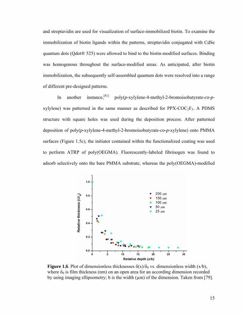
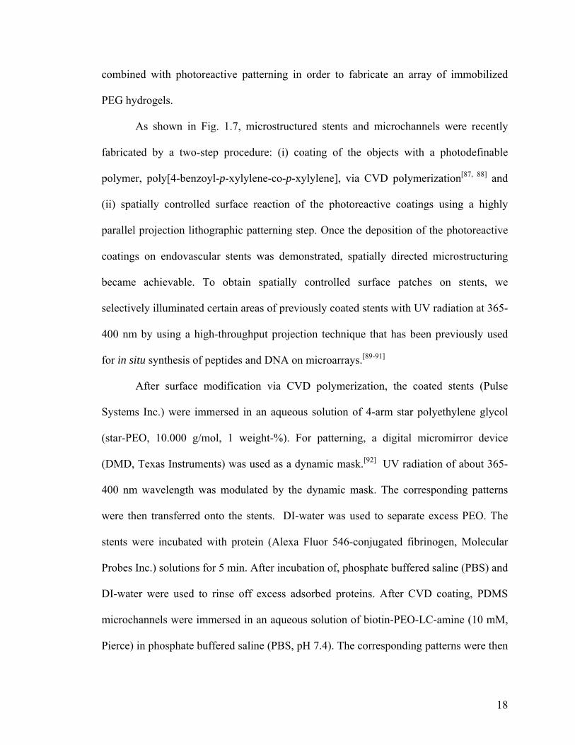
Figure 1.7. Schematic description of the 3D projection lithography technique. The method comprises two process steps: deposition of the photodefinable CVD coating (step 1) and subsequent projection lithographic rendering of the polymer-coated colloids (step 2). Inset shows an endovascular stent and a microfluidic pathway that are patterned using projection lithography. Adapted from [84] and [85].
photodefinable polymer, poly(4-benzoyl-p-xylylene-co-p-xylylene) (benzoyl-PPX), was
prepared by CVD polymerization and was used for fabrication of discontinuous surface
patterns onto 3-dimensional microscale objects.[84, 85] Due to its structural analogy to
benzophenone, the reactive coating provides light-reactive carbonyl groups that are
readily activated at wavelengths of ~340 nm. The temporarily generated free radicals
spontaneously react with adjunct molecules, mainly via C-H abstraction.[86] Suh et. al.[87]
have demonstrated the ability of benzoyl-PPX to immobilize hydrogel elements, an
important requirement in microfabrication processes. Capillary force lithography was
18
combined with photoreactive patterning in order to fabricate an array of immobilized
PEG hydrogels.
As shown in Fig. 1.7, microstructured stents and microchannels were recently
fabricated by a two-step procedure: (i) coating of the objects with a photodefinable
polymer, poly[4-benzoyl-p-xylylene-co-p-xylylene], via CVD polymerization[87, 88] and
(ii) spatially controlled surface reaction of the photoreactive coatings using a highly
parallel projection lithographic patterning step. Once the deposition of the photoreactive
coatings on endovascular stents was demonstrated, spatially directed microstructuring
became achievable. To obtain spatially controlled surface patches on stents, we
selectively illuminated certain areas of previously coated stents with UV radiation at 365-
400 nm by using a high-throughput projection technique that has been previously used
for in situ synthesis of peptides and DNA on microarrays.[89-91]
After surface modification via CVD polymerization, the coated stents (Pulse
Systems Inc.) were immersed in an aqueous solution of 4-arm star polyethylene glycol
(star-PEO, 10.000 g/mol, 1 weight-%). For patterning, a digital micromirror device
(DMD, Texas Instruments) was used as a dynamic mask.[92] UV radiation of about 365-
400 nm wavelength was modulated by the dynamic mask. The corresponding patterns
were then transferred onto the stents. DI-water was used to separate excess PEO. The
stents were incubated with protein (Alexa Fluor 546-conjugated fibrinogen, Molecular
Probes Inc.) solutions for 5 min. After incubation of, phosphate buffered saline (PBS) and
DI-water were used to rinse off excess adsorbed proteins. After CVD coating, PDMS
microchannels were immersed in an aqueous solution of biotin-PEO-LC-amine (10 mM,
Pierce) in phosphate buffered saline (PBS, pH 7.4). The corresponding patterns were then
19
transferred onto the microchannels. After rinsing, samples were incubated with
rhodamine (TRITC) conjugated streptavidin (50µg/ml, Pierce) in PBS containing 0.1%
(w/v) bovine albumin and Tween 20 (0.02% (v/v)) for 60 min. The surface was rinsed
several times with PBS containing 0.1% (w/v) bovine albumin and Tween 20 (0.02%
(v/v)). Programmable patterns were created by using a 1,024- × 768-pixel digital
micromirror device (DMD) (Fig. 1.7).
While the entire surface of the substrates was coated with the photoreactive
coating during CVD polymerization, only the areas illuminated with the DMD underwent
photochemical conversion of the carbon–oxygen double bond from the singlet ground
state into the corresponding triplet state.[93] As seen in Figure 1.7, an endovascular stent
and a microchannel were coated with the photoreactive benzoyl-PPX polymer and
subsequently exposed to the DMD grid UV patterning. The PEO-free areas facilitated
adsorption of fibrinogen, while the areas of PEO immobilization did not (inside squares).
An identical pattern of immobilized streptavidin (inside the squares) was observed within
microchannels. Despite the irregular shape and small dimensions of the objects,
homogenous chemical micropatterns were obtained on the stent surface, making possible
the progression of advanced surface architectures for medical devices.
1.3.5 Selective CVD on Metals
While the methods mentioned thus far rely on physical means to obtain spatially
controlled surface modification, an even simpler approach would be to selectively inhibit
CVD polymerization and deposition based on differences in the substrate chemistry.
Jensen et al. first reported the selective inhibition of parylene™ N, parylene™ C, as well

20
as poly(p-phenylene vinylene) (PPV) by iron and iron salts[94] and used selective CVD
polymerization to create a wide range of patterns.[94] It was also shown that, in a similar
fashion, several transitional metals, metal salts, and organometallic complexes inhibit the
growth of parylene™ N and C.[95] Suh et al. have used selective CVD polymerization
within sub-micron scale polydimethylsiloxane (PDMS) channels to yield high aspect
ratio structures. Surface-coated PDMS channels of as little as 180 nm in width were
obtained by depositing iron on the bottom of microchannels and then selectively
depositing polymer only on the channel sidewalls.[96] Recently, the first selective CVD
polymerization of a functionalized poly-p-xylylene was reported.[97] The result is a simple
patterning process that relies on selective inhibition of polymer films that can act as
chemical anchors for further surface modification via covalent immobilization.
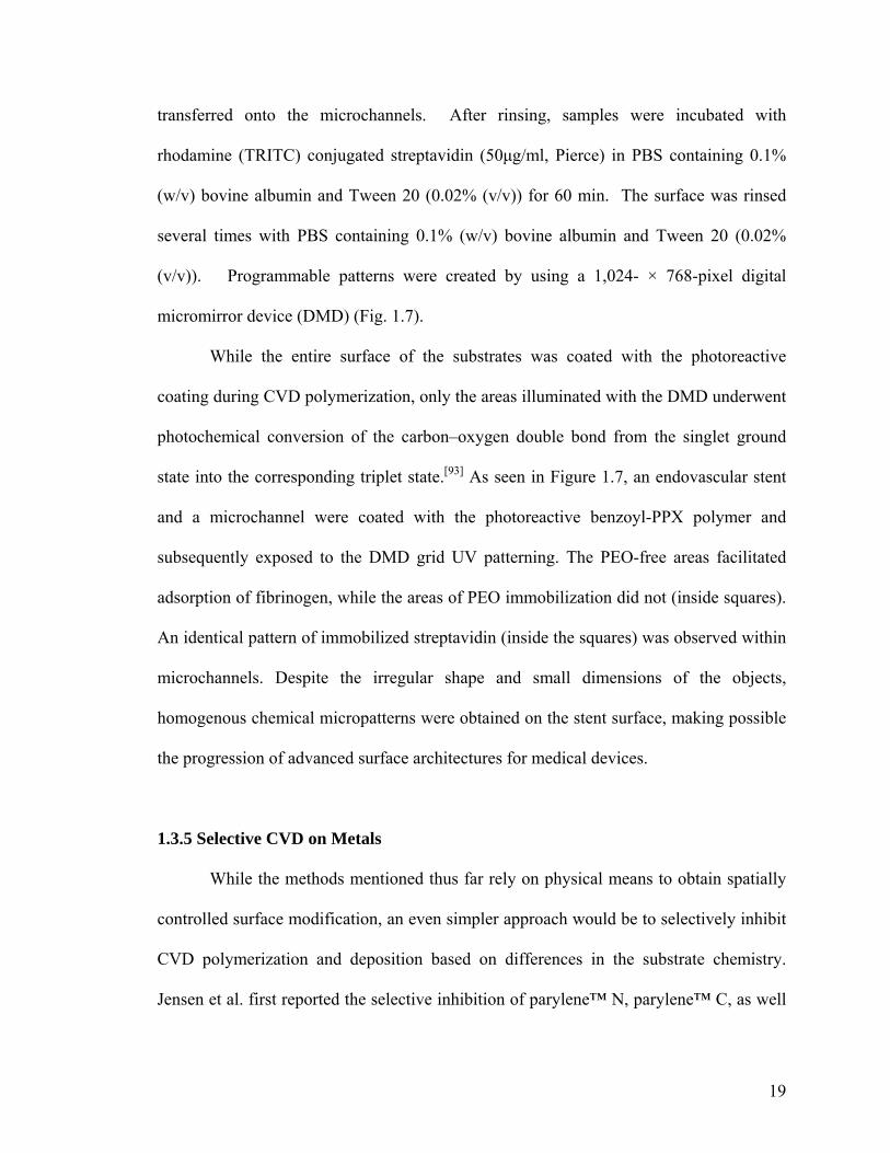
The study investigated selective inhibition of CVD polymerization by series of
metals. Based on IRRAS spectra, Ti appeared to be the only metal that effectively
inhibited the growth of poly(4-vinyl-p-xylylene-co-p-xylylene) (vinyl-PPX) during the
CVD polymerization process. Ti also inhibited CVD polymerization of poly(4-chloro-p-
xylylene). Next, a Ti-coated silicon wafer was prepared, and circles of Au were deposited
onto the Ti-coated silicon using a shadow mask. Following the protocol outlined in
Figure 1.8a, this bi-metal surface was CVD coated with vinyl-PPX and subsequently
subjected to olefin cross-metathesis reaction with fluorescein O-methacrylate. Only the
Au islands showed significant fluorescence signals (Figure 1.8b). In addition, a strong
contrast was observed between Au and the Ti surfaces providing further clarification on
the selective inhibition of chemical vapor deposition of vinyl-PPX. Moreover, Ti or Au
samples were coated with vinyl-PPX, and cross-metathesis reaction of poly(ethylene

21
glycol) methyl ether methacrylate (PEGMA) was conducted on both samples. For each
modification step, IRRAS spectra were recorded. Absorption bands at 2866, 2924, and
3013 cm-1 due to C-H symmetric and asymmetric stretching bands can be clearly detected
on the Au surface after deposition of vinyl-PPX. In addition, a strong, sharp band at 1717
(b)
(a)
(b)
(a)
Figure 1.8. (a) Schematic illustration of the selective deposition of poly(4-vinyl-p-xylylene-co-p-xylylene) on patterned Ti/Au substrates. Au was deposited through a shadow mask onto a Ti-coated silicon wafer followed by polymer deposition via CVD polymerization. Olefin cross-metathesis reaction of fluorescein O-methacrylate was used to probe the selective deposited polymer on Au surface. (b) Fluorescence micrograph reveals that only the Au islands showed appreciable signals of fluorescence. Taken from [97].

22
cm–1 indicative of the C=O bond of the ester group, and a strong band at 1110 cm–1,
which is due to C–O–C stretches of the ester group appeared after olefin cross-metathesis
reaction of OEGMA. At each modification step, no significant signal was detected on the
Ti surface, providing strong evidence that vinyl-PPX was not deposited on Ti, which
consequently prevented cross-metathesis reaction of OEGMA. The fact that the
selectively deposited reactive coatings are equipped with functional groups for further
surface modification provides a simple access route towards micro- and nanostructured
surfaces.
1.4 Hypothesis and Specific Aims
Based upon the literature survey, reactive polymer coatings have primarily
focused on controlling only one type of reaction pathway or surface property at a time.
However, biological pathways are directly affected by more than one variable. By
controlling multiple surface properties simultaneously, our goal is to improve the
manipulation of biological environments via CVD coatings. This dissertation aims to
develop reactive CVD coatings that are multifunctional in various aspects. 1) reactive
homopolymer coatings, which can vary in both reactivity and hydrophobicity; 2)
copolymer coatings, which are reactive towards multiple reaction pathways; 3) reactive
CVD coatings, which exhibit preliminary biocompatibility and maintain their reactivities;
4) CVD coatings, which possess reactive surface composition gradients. Most of the
chapters presented herein are either published or in press in various journals (Advanced
Materials, Chemical Vapor Deposition, Macromolecular Rapid Communications).[64, 98,
99]

23
1.5 Overview
The current use of CVD polymerization towards surface engineering has been
discussed. Specifically, this chapter outlined the adaptability of the CVD process towards
microfabrication of polymer thin films. Two general fabrication methods were discussed.
First, one may fabricate a biomolecular micropattern after the reactive poly(p-xylylene)
has been coated. Microcontact printing and projection lithography are two approaches
used for post-CVD surface modification. In microcontact printing, a patterned PDMS
stamp is inked with the molecule of interest, then subsequently laid upon the CVD film.
Projection lithography employs micromirrors in order to project UV light onto a
photoreactive CVD polymer coating. Secondly, one may pattern a CVD polymer onto the
substrate directly during the deposition process. Patterned replica structures mounted
onto a substrate will mask deposition over specified areas. In addition, certain polymers
have been known to deposit selectively on different metals. Thus, a patterned metal
substrate would lead to patterned polymer deposition.

24
References [1] A. Berg, W. Olthius, P. Bergveld, “Micro Total Analysis Systems” 2000, 1st edition, Kluwer, Dordrecht, The Netherlands 2000. [2] P. Li, D. J. Harrison, Transport, Anal. Chem. 1997, 69, 1564. [3] H. Mao, T. Yang, P. S. Cremer, Anal. Chem. 2002, 74, 379. [4] S. H. Chen, W. C. Sung, G. B. Lee, Z. Y. Lin, P. W. Chen, P. C. Liao, Electrophoresis 2001, 22, 3972. [5] C. S. Effenhauser, J. M. Bruin, A. Paulus, M. Ehrat, Anal. Chem. 1997, 69, 3451. [6] J. Monahan, A. A. Gewirth, R. G. Nuzzo, Electrophoresis 2002, 23, 2347. [7] J.C. Love, L.A. Estroff, J.K. Kriebel, R.G. Nuzzo, G.M. Whitesides, Chem. Rev. 2005, 105, 4, 1103. [8] D. Falconnet, G. Csucs, H.M. Grandin, M. Textor, Biomaterials 2006, 27, 16, 3044. [9] D. S. Ginger, H. Zhang, C. A. Mirkin, Angew. Chem. Int. Ed. 2004, 43, 30. [10] S. Kramer, R. R. Fuierer, C. B. Gorman, Chem. Rev. 2003, 103, 4367. [11] S. Y. Chou, P. R. Krauss, P. J. Renstrom, App. Phys. Lett. 1995, 67, 3114. [12] S. Y. Chou, P. R. Krauss, P. J. Renstrom, Science 1996, 272, 85. [13] Y. N. Xia, G. M. Whitesides, Ann. Rev. Mater. Sci. 1998, 28, 153. [14] A. Kumar, G. M. Whitesides, App. Phys. Lett. 1993, 63, 2002. [15] J. L. Wilbur, A. Kumar, E. Kim, G. M. Whitesides, Adv. Mater. 1994, 6, 600. [16] Y. N. Xia, E. Kim, X. M. Zhao, J. A. Rogers, M. Prentiss, G. M. Whitesides, Science 1996, 273, 347. [17] X. M. Zhao, Y. N. Xia, G. M. Whitesides, Adv. Mater. 1996, 8, 837. [18] E. Kim, Y. N. Xia, G. M. Whitesides, Nature 1995, 376, 581.

25
[19] E. Kim, Y. N. Xia, X. M. Zhao, G. M. Whitesides, Adv. Mater. 1997, 9, 651. [20] K. Y. Suh, Y. S. Kim, H. H. Lee, Adv. Mater. 2001, 13, 1386. [21] W. T. Tsang, A. Y. Cho, App. Phys. Lett. 1978, 32, 491. [22] T. Schallenberg, T. Borzenko, G. Schmidt, M. Obert, G. Bacher, C. Schumacher, G. Karczewski, L. W. Molenkamp, S. Rodt, R. Heitz, D. Bimberg, App. Phys. Lett. 2003, 82, 4349. [23] S. De Vusser, S. Steudel, K. Myny, J. Genoe, P. Heremans, App. Phys. Lett. 2006, 88, 103501. [24] D. C. Duffy, R. J. Jackman, K. M. Vaeth, K. F. Jensen, G. M. Whitesides, Adv. Mater. 1999, 11, 546. [25] N. Takano, L. M. Doeswijk, M. A. F. van den Boogaart, J. Auerswald, H. F. Knapp, O. Dubochet, T. Hessler, J. Brugger, Journal of Micromechanics and Microengineering 2006, 16, 1606. [26] B. R. Ringeisen, J. Callahan, P. K. Wu, A. Pique, B. Spargo, R. A. McGill, M. Bucaro, H. Kim, D. M. Bubb, D. B. Chrisey, Langmuir 2001, 17, 3472. [27] E. Ostuni, R. Kane, C. S. Chen, D. E. Ingber, G. M. Whitesides, Langmuir 2000, 16, 7811. [28] R. Pal, K. E. Sung, M. A. Burns, Langmuir 2006, 22, 5392. [29] D. G. Castner, B. D. Ratner, Surf. Sci. 2002, 500, 28. [30] P. Rai-Choudhury, “Handbook of Microlithography, Micromachining, and Microfabrication. Volume 1: Microlithography”, SPIE-The International Society for Optical Engineering, 1997. [31] F. Cerrina, Journal of Physics D: Applied Physics 2000, 33, R103.

26
[32] N. Yao, Z. L. Wang, Handbook of Microscopy for Nanotechnology, Springer, 2005. [33] A. A. Tseng, Small 2005, 1, 594. [34] D. Meschede, H. Metcalf, Journal of Physics D: Applied Physics 2003, 36, R17. [35] E. Delamarche, A. Bernard, H. Schmid, A. Bietsch, B. Michel, H. Biebuyck, J. Am. Chem. Soc. 1998, 120, 500-508. [36] S. Takayama, J.C. McDonald, E. Ostuni, M.N. Liang, P.J.A. Kenis, R.F. Ismagilov, G.M. Whitesides, Proc. Natl. Acad. Sci. U.S.A. 1999, 96, 5545-5548. [37] B. Regenberg, U. Kruehne, M. Beyer, L.H. Pedersen, M. Simon, O.R.T. Thomas, J. Nielsen, T. Ahl, Lab Chip 2004, 4, 654-657. [38] S. Takayama, E. Ostuni, P. LeDuc., K. Naruse, D.E. Ingber., G.M. Whitesides, Nature 2001, 411, 1016. [39] M. Schena, D. Shalon, R.W. Davis, P.O. Brown, Science 1995, 270, 467-470. [40] R.A. Heller, M. Schena, A. Chai, D. Shalon, T. Bedilion, J. Gilmore, D.E. Woolley, R.W. Davis, Proc. Natl. Acad. Sci. U.S.A. 1997, 94, 2150-2155. [41] D. Shalon, S.J. Smith, P.O. Brown, Genome Res. 1996, 6, 639-645. [42] M.F. Lopez, M.G. Pluskal, J. Chromatogr., B 2003, 787, 19-27. [43] A. Roda, M. Guardigli, C. Russo, P. Pasini, M. Baraldini, Biotechniques 2000, 28, 492-496. [44] A. Khademhosseini, K.Y. Suh, S. Jon, G. Eng, J. Yeh, G.J. Chen, R. Langer, Anal. Chem. 2004, 76, 3675-3681. [45] W. Zhan, G.H. Seong, R.M. Crooks, Anal. Chem. 2002, 74, 4647-4652. [46] D.J. Beebe, J.S. Moore, J.M. Bauer, Q. Yu, R.H. Liu, C. Devadoss, B.H. Jo, Nature 2000, 404, 588-590.

27
[47] J. Heo, K.J. Thomas, G.H. Seong, R.M. Crooks, Anal. Chem. 2003, 75, 22-26. [48] M. Mrksich, L.E. Dike, J. Tien, D.E. Ingber, G.M. Whitesides, Exp. Cell Res. 1997, 235, 305-313. [49] S.W. Rhee, A.M. Taylor, C.H. Tu, D.H. Cribbs, C.W. Cotman, N.L. Jeon, Lab Chip 2005, 5, 102-107. [50] S.D. Senturia. “Microsystem Design”, Kluwer Academic Publishers, 2000. [51] Y.C. Chang, C.W. Frank, Langmuir 1998, 14, 326. [52] N.H. Lee, C.W. Frank, Langmuir 2003, 19, 1295. [53] Y. Mao, K.K. Gleason, Langmuir 2004, 20, 2484; [54] T.P. Martin, K.K. Gleason, Chem. Vap. Dep. 2006, 12, 685. [55] W.F. Gorham, J. Polym. Sci., Part A-1 1966, 4, 3027. [56] J.B. Fortin, T.M. Lu, Chem. Mater. 2002, 14, 1945-1949. [57] [a] C.E. Morosanu, “Thin Films by Chemical Vapor Deposition”, Elsevier, New
York 1990 [b] M.L. Hitchman, K.F. Jensen, “Chemical Vapor Deposition”, Academic
Press, New York, 1993.
[58] W. F. Beach, Macromolecules 1978, 11, 72. [59] A. Zangwill, “The Physics at Surfaces” Cambridge University Press: Cambridge,
1988.
[60] J. Lahann, D. Klee, H. Hocker, Macromol. Rapid Commun. 1998, 19, 441. [61] J. Lahann, M. Balcells, T. Rodon, J. Lee, I.S. Choi, K.F. Jensen, R. Langer, Langmuir 2002, 18, 3632. [62] J. Lahann, R. Langer, Macromolecules 2002, 35, 4380. [63] J. Lahann, Polym. Inter. 2006, 55, 1361.

28
[64] Y. Elkasabi, M. Yoshida, H. Nandivada, H.Y. Chen, J. Lahann, Macromol. Rapid Comm. 2008, 29, 855-870. [65] M. Morgen, S.H. Rhee, J.H. Zhao, I. Malik, T. Ryan, H.M. Ho, M.A. Plano, P. Ho, Macromolecules 1999, 32, 7555. [66] J.J. Senkevich, S.B. Desu, V. Simkovic, Polymer 2000, 41, 2379. [67] S.Y. Park, S.N. Chvalun, A.A. Nikolaev, K.A. Mailyan, A.V. Pebalk, I.E. Kardash, Polymer 2000, 41, 2937. [68] D. Klee, N. Weiss, J. Lahann, “Vapor-Based Polymerization of Functionalized [2.2]Paracyclophanes: A Unique Approach towards Surface-Engineered Microenvironments” Chapter 18, Modern Cyclophane Chemistry, Wiley-VCH, Weinheim 2004, p463. [69] H. Nandivada, H.Y. Chen, J. Lahann, Macromol. Rapid Comm. 2005, 26, 1794. [70] G. T. Hermanson, “Bioconjugate Techniques”, 1st edition, Academic, San Diego, CA 1996. [71] D. N. Moothoo, J. H. Naismith, Acta Crystallogr., Sect. D: Biol. Crystallogr. 1999, D55(1), 353. [72] S. Thenevet, H.Y. Chen, J. Lahann, F. Stellacci, Adv. Mater. 2007, 19, 4333. [73] H. Nandivada, H.Y. Chen, L. Bondarenko, J. Lahann, Angew. Chem. Int. Ed. 2006, 45, 3360. [74] V. V. Rostovtsev, L. G. Green, V. V. Fokin, K. B. Sharpless, Angew. Chem. 2002, 114, 2708-2711; Angew. Chem. Int. Ed. 2002, 41, 2596-2599. [75] H.Y. Chen, Y. Elkasabi, J. Lahann, J. Amer. Chem. Soc. 2006, 128, 374. [76] J.C. McDonald, G.M. Whitesides, Acc. Chem. Res. 2002, 35, 491-499. [77] H. W. Gu, R. K. Zheng, X. X. Zhang, B. Xu, Adv. Mater. 2004, 16, 1356.

29
[78] M. Graff, S. K. Mohanty, E. Moss, A. B. Frazier, Journal of Microelectromechanical Systems 2004, 13, 956. [79] H.Y. Chen, J. Lahann, Adv. Mater. 2007, 19, 3801. [80] G. T. Hermanson, Bioconjugate Techniques, Academic Press, 1996. [81] X. Jiang, H.Y. Chen, G. Galvan, M. Yoshida, J. Lahann, Adv. Func. Mater. 2008, 18, 27. [82] E. M. Tolstopyatov, Journal of Physics D-Applied Physics 2002, 35, 1516. [83] E. M. Tolstopyatov, S. H. Yang, M. C. Kim, Journal of Physics D-Applied Physics 2002, 35, 2723. [84] H.Y. Chen, J.M. Rouillard, E. Gulari, J. Lahann, Proc. Nat. Acad. Sci. 2007, 104, 11173. [85] H.Y. Chen, J.M. Rouillard, E. Gulari, J. Lahann, PMSE Preprints 2006, 95, 125. [86] W. W. Shen, S.G. Boxer, W. Knoll, C.W. Frank, Biomacromol. 2001, 2, 70-79. [87] K.Y. Suh, R. Langer, J. Lahann, Adv. Mater. 2004, 16, 1401. [88] H.Y. Chen, J. Lahann, Anal. Chem. 2005, 77, 6909. [89] J. Tian, H Gong, N. Sheng, X. Zhou, E. Gulari, X. Gao, G. Church, Nature 2004, 432, 1050. [90] J.P. Pellois, X. Zhou, O. Srivannavit, T. Zhou, E. Gulari, X. Gao, Nat. Biotech. 2002, 20, 922. [91] X.L. Gao, X.C. Zhou, E. Gulari, Proteomics 2003, 3, 2135. [92] X. Gao, E. LeProust, H. Zhang, O. Srivannavit, E. Gulari, P. Yu, C. Nishiguchi, Q. Xiang, X. Zhou, Nucleic Acids Research 2001, 29, 4744-4750. [93] K.S. Taton, P.E. Guire, Colloids Surf B 2002, 24, 123–132. [94] K. M. Vaeth, K. F. Jensen, Adv. Mater. 1999, 11, 814.

30
[95] K. M. Vaeth, K. F. Jensen, Chem. Mater. 2000, 12, 1305. [96] K. Y. Suh, R. Langer, J. Lahann, App. Phys. Lett. 2003, 83, 4250. [97] H.Y. Chen, J.H. Lai, X. Jiang, J. Lahann, Adv. Mater. 2008, 20, 3474. [98] Y. Elkasabi, H.Y. Chen, J. Lahann, Adv. Mater. 2006, 18, 1521. [99] Y. Elkasabi, J. Lahann, Macromol. Rapid Comm. 2009, 30, 57.

31
CHAPTER 2
MULTIFUNCTIONAL HOMOPOLYMER COATINGS
The materials in this chapter have been adapted with minor modifications from
the following article: Y. Elkasabi, H. Nandivada, H.Y. Chen, S. Bhaskar, J. D’Arcy, L.
Bondarenko, J. Lahann, “Partially Fluorinated Poly-p-xylylenes Synthesized by Chemical
Vapor Deposition Polymerization”, Chemical Vapor Deposition 2009, in press.
2.1 Background and Motivations
Surface wettability is an important attribute of a coating, which determines the suitability
of surfaces for a range of different applications. In this respect, fluorinated polymer
coatings with low surface energy are particularly attractive due to their water-repellence,
inertness, and low coefficient of friction.[1, 2] Fluorinated polymer films synthesized using
CVD polymerization such as poly(octafluoro-p-xylylene) (also known as parylene-AF4)
and poly(tetrafluoro-p-xylylene) (VT-4) have exhibited excellent optical properties, low
dielectric constants and high thermal stability.[3, 4] Despite these interesting properties,
these coatings typically lack reactive functional groups for further surface modification.
Several functionalized poly-p-xylyenes have been synthesized via CVD polymerization
of substituted [2.2]paracyclophanes, creating a wide range of different reactive polymer
coatings.[5, 6, 7] In order to incorporate the potential advantages of fluorinated polymers
with the concept of reactive polymer coatings, fluorinated and reactive moieties can be

32
Scheme 2.1: Mechanism of CVD polymerization of partially fluorinated [2.2]paracyclophanes to yield the corresponding poly-p-xylylenes. Polymer 2 is fluorinated at the aliphatic bridge, whereas polymer 4 contains a fluorinated reactive group at the aromatic ring.
simultaneously introduced into [2.2]paracyclophanes, which are subsequently deposited
via CVD polymerization. This can be achieved either through modification of the
aliphatic bridges or by substitution at the aromatic rings.
Taking the aliphatic route, we intended to synthesize a fluorinated polymer coating,
poly(4,12-dibromo-1,1,9,9-tetrafluoro-p-xylylene) (2) via CVD polymerization of
precursor 4,12-dibromo-1,1,9,9-tetrafluoro[2.2]paracyclophane (1), which is partially
fluorinated at the aliphatic bridge (Scheme 2.1). This polymer contains bromine at the
aromatic ring, which may be further converted into reactive groups providing easy access
for subsequent surface modification reactions. In fact, CVD polymerized brominated-
PPX coatings are known to undergo dehydrohalogenation resulting in vinyl and ethynyl
33
moieties.[8] However, post-polymerization modification of the brominated aromatic ring
may require harsh chemical conditions. Hence, we alternatively explored incorporation of
functional groups into the aromatic segments that may combine reactivity with high
hydrophobicity. In the past, several poly-p-xylylenes have been synthesized with shorter
fluorinated side chains resulting in relatively hydrophobic coatings.[5, 9-12] To further
investigate this effect, we have now synthesized and CVD-polymerized a
[2.2]paracyclophane with a long perfluorinated side chain. Specifically, 4-
heptadecafluorononanoyl[2.2]paracyclophane (3) was synthesized and used to prepare
ultrahydrophobic coatings of poly(4-heptadecafluorononanoyl-p-xylylene-co-p-xylylene)
(4) which contained a carbonyl-functionalized derivative with an 8-carbon perfluorinated
side chain (Scheme 2.1). Given the usefulness of non-functionalized as well as the
perfluorinated PPX for coating applications,[3, 4, 13, 14] widening the scope of CVD
polymerization by applying this technique to reactive, yet partially fluorinated
paracyclophanes may significantly advance the field of low-surface energy coatings. Not
only do new polymer coatings, such as polymer 4, possess robust chemical properties, but
their reactivity also allows for subsequent surface modifications.
2.2 Experimental Methods
Precursor synthesis Compound 4,12-dibromo-1,1,9,9-tetrafluoro[2.2]paracyclophane
(1) was synthesized according to a previously-established synthesis chemistry.[15]
Precursor, 4-heptadecafluorononanoyl[2.2]paracyclophane (3) was synthesized by
Friedel-Crafts acylation of [2.2]paracyclophane with the corresponding acid chloride
(heptadecafluorononanoyl chloride 98%, Apollo Scientific Ltd., Cheshire, UK).

34
Aluminum chloride (0.96 g) was dissolved in 30 mL of dichloromethane under inert
conditions. The suspension was cooled down to -40 oC with constant stirring. The acid
chloride (2.5 g, 5.2 mmol) was slowly added into this mixture using a syringe.
Dichloromethane (10 mL) was further added to the suspension. After 20 min,
[2.2]paracyclophane (1 g, 4.8 mmol) was slowly added to the suspension. The reaction
continued with vigorous stirring at -40 oC for 45 min, and then the mixture was allowed
to reach 0 oC over a period of 1 h. The reaction was quenched with aqueous HCl, and
ethyl acetate was added to the organic phase to increase solubility of the heavy products.
The organic layer was separated and subsequently washed with 10 mL each of DI H2O,
0.5M Na2CO3, and 0.5M NaOH. After purification with column chromatography (1:40
ethyl acetate:hexane), the product was diluted with hexane. Hexane was then removed in
volumetric increments using a rotovap. After each increment, the unreacted
[2.2]paracyclophane was allowed to precipitate, with the final product still in solution. In
the final increment, pure 3 (1.1 g) crystallized at the bottom of the flask.
CVD polymerization of precursors Starting materials 1 and 3 were sublimed at 80-90
oC under vacuum and pyrolyzed into the corresponding quinodimethanes, which
spontaneously polymerized upon condensation onto the substrate surface (at 10-15 oC).
A constant argon flow of 20 sccm was used as the carrier. Starting material 1 pyrolyzed
at 720 °C, and compound 3 pyrolyzed at 620 oC. Subsequently, polymerization occurred
on a rotating, cooled sample holder placed inside a stainless steel chamber with a wall
temperature of 120 °C. The pressure was set at 0.3 mbar or lower.
35
Characterization 1H, 13C and 19F NMR spectra were recorded using a Varian Inova 400,
1H NMR (400 MHz), 13C NMR (100.6 MHz), 19F NMR (376 MHz) spectrometer.
Chemical shifts (δ) are expressed in ppm downfield from tetramethylsilane using the
residual non-deuterated solvent as internal standard (CDCl3: 1H: δ = 7.22; 13C: δ = 77.00).
Infrared spectroscopy was performed on a Nicolet 6700 spectrometer utilizing the
grazing angle accessory (Smart SAGA) at a grazing angle of 85o. Mass spectra were
recorded using a VG (Waters) 70-250-S Magnetic sector mass spectrometer (EI, 70 eV)
on a DCI desorption probe. The instrument was scanned from m/z 1000 to m/z 35 and
was calibrated with perfluorokerosene-H. X-ray photoelectron spectroscopy (XPS) data
were recorded on an Axis Ultra X-ray photoelectron spectrometer (Kratos Analyticals,
UK) equipped with a monochromatized Al Kα X-ray source. In these experiments, pass
energy was set to 160.0 eV with an X-ray power of 150 kW, and the aperture was 600
µm x 600 µm. Thickness measurements were recorded at a wavelength of 532 nm using
an EP3-SW ellipsometry (Nanofilm Technologie GmbH, Germany). Nulling experiments
were performed at an angle of incidence of 60o, and an anisotropic Cauchy model was
used to model the ellipsometric parameters psi and delta. Surface morphology was
examined by scanning electron microscopy (Philips XL30 ESEM, high vacuum mode).
Polymer 2: XPS (atomic ratios): Br3p/C1s: 11.3% (calc: 12.5%), C-Br/C-C: 13.9% (calc:
16.7%), F1s/C1s: 17.7% (calc: 25.0%), C-F/C-C: 14.0% (calc: 16.7%); FTIR (grazing
angle 85o): ν (cm-1) = 842, 886, 1056, 1089, 1132, 1157, 1245, 1326, 1392, 1430, 1493,
1563, 1609, 1811, 2848, 2939, 3037, 3072.

36
Precursor 3: 1H NMR (400 MHz, CDCl3): δ = 2.9-3.3 (7H, CH2), 3.6 (1H, CH2), 6.3 (1H,
CH), 6.5 (4H, CH), 6.75 (1H, CH), 7.0 (1H, CH). 13C NMR (100 MHz, CDCl3): δ =
34.90, 34.92, 34.99, 35.85, 107.50, 110.22, 110.52, 110.69, 111.18, 112.93, 115.66,
118.52, 130.87, 131.04, 132.45, 132.70, 132.85, 133.43, 136.61, 138.54, 139.37, 139.79,
139.93, 144.38, 184.84. 19F NMR (376 MHz, CDCl3): δ = -80.8, -110.9, -111.9, -112.5, -
113.6, -120.6, -120.9, -121.8, -122.7, -126.1. EI (70 eV): m/z (%) = 654.2 (43.8) [M+],
550.1 (7.4) [C8H7COC8F17+], 235 (4.7) [C16H15CO+], 131.1 (14.8) [C8H7CO+], 104.1
(100) [C8H8+]. FTIR (grazing angle 85o): ν (cm-1) = 2931, 2852, 1707, 1591, 1549, 1500,
1371, 1329, 1248, 1198, 1146, 1116, 1070, 997, 960, 935, 843.
Polymer 4: XPS (atomic ratios): F1s/C1s: 86.4 (calc. 85.6%), O1s/C1s: 5.9% (calc. 5.0%).
FTIR (grazing angle 85o): ν (cm-1) = 2934, 1714, 1568, 1498, 1458, 1416, 1370, 1330,
1251, 1222, 1154, 1061, 1005, 943, 880, 811.
Contact angle measurements A microsyringe was used to place a 5 µl droplet on the
substrate, and picture of the droplet was captured using a digital camera (Canon EOS
20D) after 5 s. An image processing software (Image J) was used to analyze the droplet
images and calculate the contact angle.
Immobilization of biotinamidocaproyl hydrazide PDMS stamps were fabricated as
described in literature. The PDMS stamp consisted of square-shaped indentations (400
µm on a side) with 50 µm gaps between the square edges. The PDMS stamp was treated
with UV-ozone for 25 min (UV-Ozone Cleaner; Model no. 342, Jelight company Inc.),

37
then inked with a 10 mM solution of biotinamidocaproyl hydrazide (Pierce
Biotechnology, IL) in ethanol at a pH of 5-6. The inked surface was then stamped onto a
surface coated with polymer 4. The stamp was kept in contact with the substrate for 1
min and then the patterned substrate was incubated with rhodamine-labeled streptavidin
(50 µg/ml, Pierce Biotechnology, IL) or streptavidin labeled with Alexa Fluor 633 (50
µg/ml, Invitrogen, CA) in an aqueous phosphate buffer solution (pH 7.4, Sigma, MO)
consisting of bovine serum albumin (0.1% w/v, Sigma, MO) and Tween 20 (0.02% v/v,
Sigma, MO) for 1 h. The substrate was washed three times with the incubating buffer and
rinsed with DI-water. The micropatterns on the substrate were visualized using a Nikon
TE200 fluorescence microscope and confocal laser scanning microscope (CLSM)
(Olympus FluoView 500, USA).
2.3 Results and Discussion
2.3.1 Precursor Synthesis and Characterization
4,12-Dibromo-1,1,9,9-tetrafluoro[2.2]paracyclophane, 1, was synthesized and
characterized as previously described.[15] In principle, presence of bromine may allow
subsequent modifications of the polymer, albeit harsh conditions may have to be
employed. On the other hand, 4-heptadecafluorononanoyl[2.2]paracyclophane, 3, was
synthesized as described previously for similar compounds[10, 16] using Friedel-Crafts
acylation of the commercially available [2.2]paracyclophane with
heptadecafluorononanoyl chloride in the presence of AlCl3. To control the reaction, the
synthesis was carried out at low temperatures (-40 to -30 oC) in dichloromethane. Even
slightly elevated temperatures close to 0 oC caused an uncontrollable reaction and

38
resulted in loss of the paracyclophane and in-solution polymerization, which resulted in
insoluble byproducts.
The chemical structure of compound 3 was analyzed using nuclear magnetic resonance
(NMR) spectroscopy and mass spectrometry (MS). Both 1H-NMR and 13C-NMR
confirmed the expected structure of paracyclophane 3. Mass spectrometry conducted
during CVD polymerization further confirmed the structure of compound 3 revealing a
mass peak at 654 Da (M+) and characteristic peaks at 550 Da and 104 Da corresponding
to the two quinodimethanes (C8H7COC8F17+, C8H8+), respectively.
2.3.2 CVD Polymerization and Characterization
Once the synthesis of functionalized fluorinated [2.2]parcyclophanes was achieved, we
addressed the question of whether they would lend themselves to CVD polymerization
without loss of the functional groups. For CVD polymerization, precursor 1 was
sublimated under a reduced pressure of 0.2 mbar and a temperature of 80 °C. The argon
carrier gas transported the vaporized 1 into the pyrolysis zone, which was heated to
720 °C to ensure cleavage of the C-C bonds of the bridge, resulting in the corresponding
quinodimethanes (monomers). Finally, these monomers were adsorbed on the substrate,
which was maintained at 10-15 °C, where they spontaneously polymerized. This process
resulted in transparent and topologically uniform films of polymer 2 with thicknesses
between 20 and 50 nm, as determined by ellipsometry. These polymer films were
amorphous, as confirmed by X-ray diffraction (XRD) studies. Moreover, polymer 2 was
deposited on a wide range of materials, including polymers (polyethylene, polystyrene),
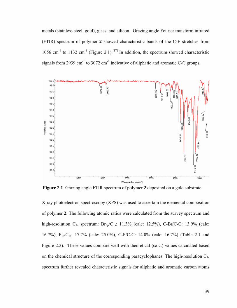
39
Figure 2.1. Grazing angle FTIR spectrum of polymer 2 deposited on a gold substrate.
metals (stainless steel, gold), glass, and silicon. Grazing angle Fourier transform infrared
(FTIR) spectrum of polymer 2 showed characteristic bands of the C-F stretches from
1056 cm-1 to 1132 cm-1 (Figure 2.1).[17] In addition, the spectrum showed characteristic
signals from 2939 cm-1 to 3072 cm-1 indicative of aliphatic and aromatic C-C groups.
X-ray photoelectron spectroscopy (XPS) was used to ascertain the elemental composition
of polymer 2. The following atomic ratios were calculated from the survey spectrum and
high-resolution C1s spectrum: Br3p/C1s: 11.3% (calc: 12.5%), C-Br/C-C: 13.9% (calc:
16.7%), F1s/C1s: 17.7% (calc: 25.0%), C-F/C-C: 14.0% (calc: 16.7%) (Table 2.1 and
Figure 2.2). These values compare well with theoretical (calc.) values calculated based
on the chemical structure of the corresponding paracyclophanes. The high-resolution C1s
spectrum further revealed characteristic signals for aliphatic and aromatic carbon atoms

40
Polymer 2 Polymer 4 BE (eV) Expt. (%) Calc. (%) BE (eV) Expt. (%) Calc. (%) C-C 285.0 74.1 75.0 285.3 42.6 49.63 C-Br 285.9 10.7 12.5 -- -- -- C-C=O -- -- -- 286.9 3.7 5.04 C=O -- -- -- 288.8 5.7 5.04 C-F 289.9 11.0 12.5 -- -- -- π π* 291.6 4.2 -- 291.1 4.1 -- CF2 -- -- -- 292.0 38.2 35.25 CF3 -- -- -- 294.2 5.7 5.04 Table 2.1: High resolution C1s XPS data for polymers 2 and 4.
(C-C, C-H) (normalized to 285.0 eV), carbon attached to bromine (C-Br) at 285.9 eV,
carbon-fluorine (C-F) at 289.9 eV, and a signal indicating π π* transitions at 291.6 eV.
The latter is a characteristic of aromatic molecules and has been previously reported for
similar poly-p-xylylenes.[5] The XPS data in conjunction with FTIR spectrum strongly
suggests that the chemical structure of the synthesized CVD polymer film 2 was as
expected (shown in Scheme 2.1).
Figure 2.2: XPS survey spectrum of polymer 2; inset shows the high-resolution C1s spectrum.
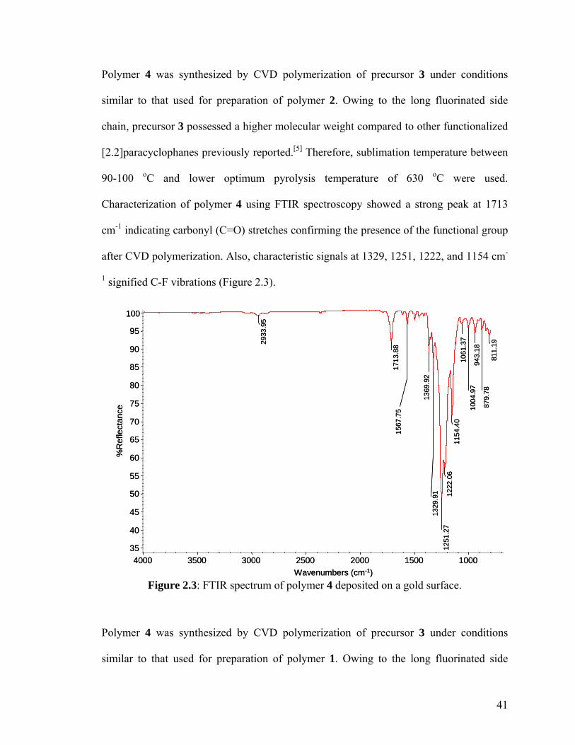
41
811.
1987
9.78
943.
1810
04.9
710
61.3
711
54.4
012
22.0
612
51.2
713
29.9
113
69.9
2
1567
.75
17
13.8
82933
.95
35
40
45
50
55
60
65
70
75
80
85
90
95
100
%R
efle
ctan
ce
1000 1500 2000 2500 3000 3500 4000 Wavenumbers (cm-1)
811.
1987
9.78
943.
1810
04.9
710
61.3
711
54.4
012
22.0
612
51.2
713
29.9
113
69.9
2
1567
.75
17
13.8
82933
.95
35
40
45
50
55
60
65
70
75
80
85
90
95
100
%R
efle
ctan
ce
1000 1500 2000 2500 3000 3500 4000 Wavenumbers (cm-1)
Figure 2.3: FTIR spectrum of polymer 4 deposited on a gold surface.
Polymer 4 was synthesized by CVD polymerization of precursor 3 under conditions
similar to that used for preparation of polymer 2. Owing to the long fluorinated side
chain, precursor 3 possessed a higher molecular weight compared to other functionalized
[2.2]paracyclophanes previously reported.[5] Therefore, sublimation temperature between
90-100 oC and lower optimum pyrolysis temperature of 630 oC were used.
Characterization of polymer 4 using FTIR spectroscopy showed a strong peak at 1713
cm-1 indicating carbonyl (C=O) stretches confirming the presence of the functional group
after CVD polymerization. Also, characteristic signals at 1329, 1251, 1222, and 1154 cm-
1 signified C-F vibrations (Figure 2.3).
Polymer 4 was synthesized by CVD polymerization of precursor 3 under conditions
similar to that used for preparation of polymer 1. Owing to the long fluorinated side

42
C1sC1s
Figure 2.4: XPS survey spectrum of polymer 4; inset shows the high-resolution C1s spectrum.
chain, precursor 3 possessed a higher molecular weight compared to other functionalized
[2.2]paracyclophanes.[5] Therefore, a sublimation temperature between 90-100 oC and
lower optimum pyrolysis temperature of 630 oC were used. Characterization of polymer 4
using FTIR spectroscopy showed a strong peak at 1713 cm-1 indicating carbonyl (C=O)
stretches confirming the presence of the functional group after CVD polymerization.
Also, the vibration band at 1329, 1251, 1222, and 1154 cm-1 signified the presence of C-F
bonds.
Similar to polymer 2, the XPS-based atomic ratios for polymer 4 were in good agreement
with theoretical calculations (Table 2.1). Figure 2.4 shows the survey and high-resolution
C1s XPS spectra for polymer 4. In the high-resolution C1s spectrum, a binding energy of

43
60.0
70.0
80.0
90.0
100.0
110.0
120.0
PPX PPX-COCF3 PPX-COC2F5 PPX-COC8F17(4)
TFPPX-Br2(2)
Con
tact
Ang
le (o
)
60.0
70.0
80.0
90.0
100.0
110.0
120.0
PPX PPX-COCF3 PPX-COC2F5 PPX-COC8F17(4)
TFPPX-Br2(2)
Con
tact
Ang
le (o
)
Figure 2.5: Comparing contact angles of non-functionalized PPX, polymer 2, PPX-COCF3, PPX-COC2F5 and polymer 4.
288.8 eV indicated the carbonyl carbon (C=O). Furthermore, the ratio of C-F3 to C-F2
carbons equals 0.143, which agreed well with the calculated value of 0.149, indicating
preservation of the fluorinated ketone. Overall, the high-resolution XPS spectrum
confirmed the FTIR results.
Water contact angle measurements of the polymers provided an insight into the degree of
hydrophobicity of the polymers. Polymers 2 and 4 were compared to non-functionalized
PPX films and two previously reported poly-p-xylylenes with shorter fluorinated side
groups namely, poly(4-trifluoroacetyl-p-xylylene-co-p-xylylene) (PPX-COCF3) and
poly(4-pentafluoropropionyl-p-xylylene-co-p-xylylene) (PPX-COC2F5).[9,10,12]
Differences in the functionalities and chain lengths influenced the contact angles in such
a manner that a greater degree of fluorination increased the contact angle (Figure 2.5).

44
(a)
(b)
100 µm 100 µm
100 µm 100 µm
(a)
(b)
100 µm 100 µm
100 µm 100 µm
Figure 2.6: Adhesion tests of (a) polymer 2 and (b) polymer 4. The polymer surface was first marked using a sharp object and then scotch tape was pressed onto the surface. The surface was observed before and after peeling off the tape. Optical micrographs before and after testing are shown on the left and right panels, respectively. IR spectra remained identical before and after testing.
Polymers 2 and 4 were also deposited on a variety of different substrates such as gold,
silicon, glass, and PDMS on which they showed good adhesion. To ascertain the
adhesiveness of the polymers, a piece of scotch tape was first pressed onto the film and
then released by peeling it off.[18] The robustness of the film was examined visually
(Figure 2.6) and FTIR was used for further confirmation. The films also remained stable
after ultrasonication in water for 15-20 min. Moreover, polymers 2 and 4 were stable in
aqueous solutions and several organic solvents such as ethanol, acetone, methanol,
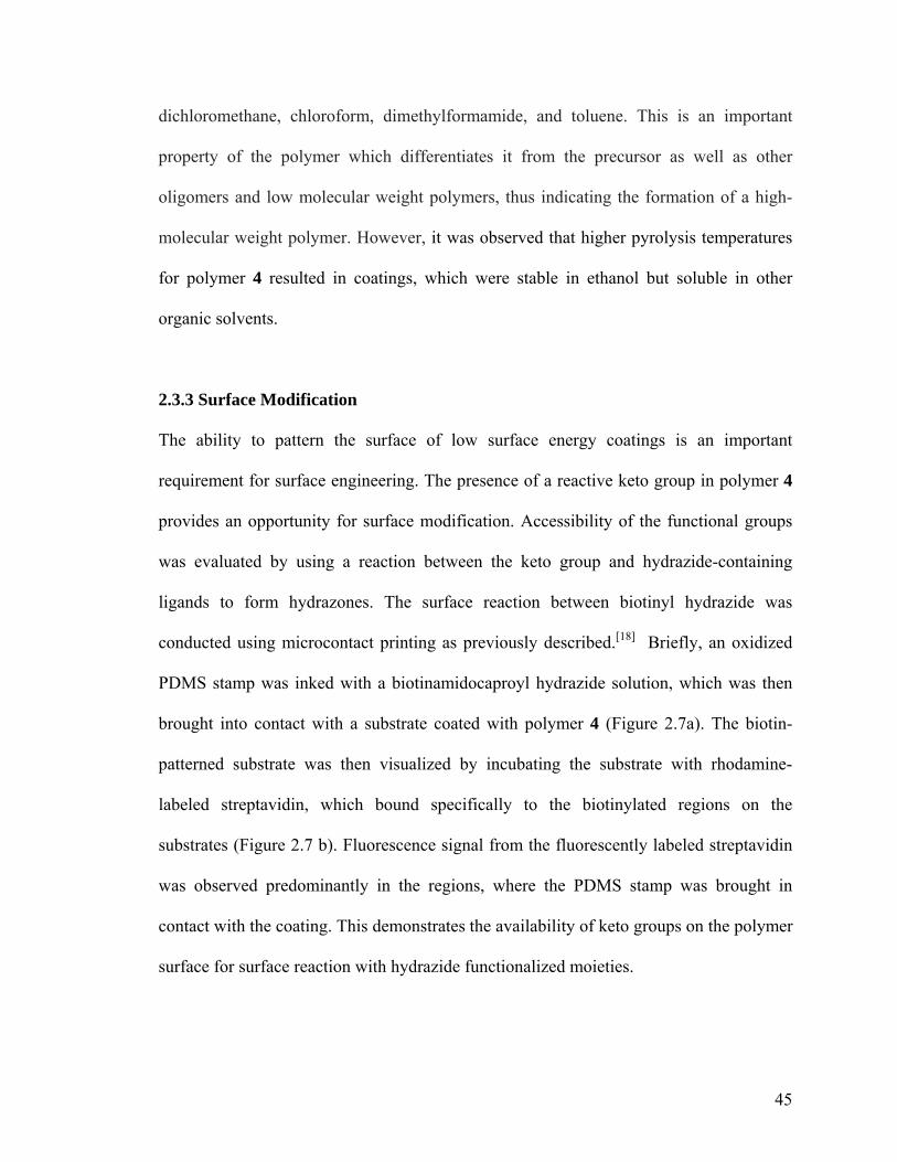
45
dichloromethane, chloroform, dimethylformamide, and toluene. This is an important
property of the polymer which differentiates it from the precursor as well as other
oligomers and low molecular weight polymers, thus indicating the formation of a high-
molecular weight polymer. However, it was observed that higher pyrolysis temperatures
for polymer 4 resulted in coatings, which were stable in ethanol but soluble in other
organic solvents.
2.3.3 Surface Modification
The ability to pattern the surface of low surface energy coatings is an important
requirement for surface engineering. The presence of a reactive keto group in polymer 4
provides an opportunity for surface modification. Accessibility of the functional groups
was evaluated by using a reaction between the keto group and hydrazide-containing
ligands to form hydrazones. The surface reaction between biotinyl hydrazide was
conducted using microcontact printing as previously described.[18] Briefly, an oxidized
PDMS stamp was inked with a biotinamidocaproyl hydrazide solution, which was then
brought into contact with a substrate coated with polymer 4 (Figure 2.7a). The biotin-
patterned substrate was then visualized by incubating the substrate with rhodamine-
labeled streptavidin, which bound specifically to the biotinylated regions on the
substrates (Figure 2.7 b). Fluorescence signal from the fluorescently labeled streptavidin
was observed predominantly in the regions, where the PDMS stamp was brought in
contact with the coating. This demonstrates the availability of keto groups on the polymer
surface for surface reaction with hydrazide functionalized moieties.
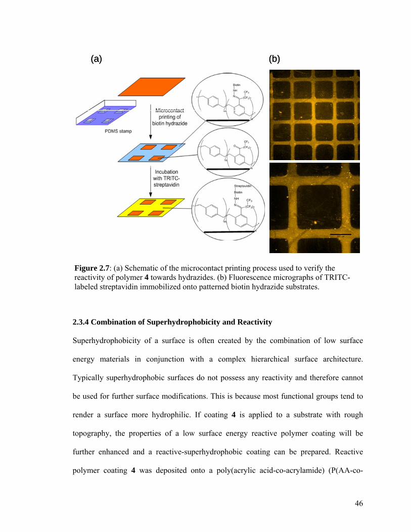
46
(a) (b)(a) (b)
Figure 2.7: (a) Schematic of the microcontact printing process used to verify the reactivity of polymer 4 towards hydrazides. (b) Fluorescence micrographs of TRITC-labeled streptavidin immobilized onto patterned biotin hydrazide substrates.
2.3.4 Combination of Superhydrophobicity and Reactivity
Superhydrophobicity of a surface is often created by the combination of low surface
energy materials in conjunction with a complex hierarchical surface architecture.
Typically superhydrophobic surfaces do not possess any reactivity and therefore cannot
be used for further surface modifications. This is because most functional groups tend to
render a surface more hydrophilic. If coating 4 is applied to a substrate with rough
topography, the properties of a low surface energy reactive polymer coating will be
further enhanced and a reactive-superhydrophobic coating can be prepared. Reactive
polymer coating 4 was deposited onto a poly(acrylic acid-co-acrylamide) (P(AA-co-
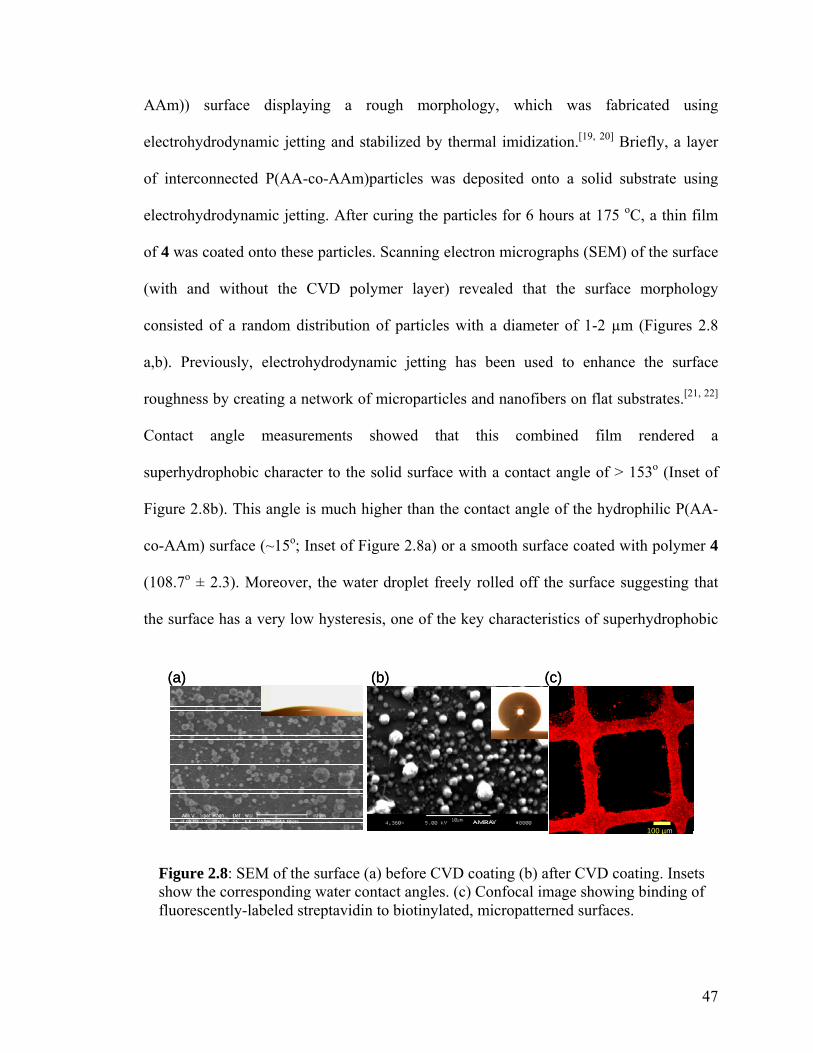
47
100 µm
(a) (b) (c)
100 µm100 µm
(a) (b) (c)
Figure 2.8: SEM of the surface (a) before CVD coating (b) after CVD coating. Insets show the corresponding water contact angles. (c) Confocal image showing binding of fluorescently-labeled streptavidin to biotinylated, micropatterned surfaces.
AAm)) surface displaying a rough morphology, which was fabricated using
electrohydrodynamic jetting and stabilized by thermal imidization.[19, 20] Briefly, a layer
of interconnected P(AA-co-AAm)particles was deposited onto a solid substrate using
electrohydrodynamic jetting. After curing the particles for 6 hours at 175 oC, a thin film
of 4 was coated onto these particles. Scanning electron micrographs (SEM) of the surface
(with and without the CVD polymer layer) revealed that the surface morphology
consisted of a random distribution of particles with a diameter of 1-2 µm (Figures 2.8
a,b). Previously, electrohydrodynamic jetting has been used to enhance the surface
roughness by creating a network of microparticles and nanofibers on flat substrates.[21, 22]
Contact angle measurements showed that this combined film rendered a
superhydrophobic character to the solid surface with a contact angle of > 153o (Inset of
Figure 2.8b). This angle is much higher than the contact angle of the hydrophilic P(AA-
co-AAm) surface (~15o; Inset of Figure 2.8a) or a smooth surface coated with polymer 4
(108.7o ± 2.3). Moreover, the water droplet freely rolled off the surface suggesting that
the surface has a very low hysteresis, one of the key characteristics of superhydrophobic
48
surfaces.[23-25] Finally to demonstrate the reactivity of polymer 4, the surface was reacted
with biotinamidocaproyl hydrazide (as previously described in Section 2.2.3) and
incubated with Alexa Fluor 633 Streptavidin. Analysis with confocal scanning laser
microscopy confirmed the reactivity of this superhydrophobic surface towards hydrazide-
containing ligands (Figure 2.8c).
2.4 Conclusions
In summary, we have synthesized and polymerized two partially fluorinated
[2.2]paracyclophane precursors with aliphatic or aromatic functionalization. Precursor 1
is fluorinated at the aliphatic bridge and may allow for further functionalization of the
aromatic rings because of the presence of bromine groups. Precursor 3 contained a highly
fluorinated keto group at the aromatic ring. Deposition of these polymers using CVD
yielded coatings 3 and 4 that were stable in a range of different organic solvents and
aqueous solutions. Polymer 4 was also shown to be reactive towards hydrazide-
functionalized biotin, which then linked readily with fluorescently-labeled streptavidin.
Finally, polymer coating 4 was applied towards the fabrication of reactive-
superhydrophobic coatings. This class of functionalized, fluorinated poly-p-xylylenes
could be of great interest as low energy reactive vapor-based coatings for biomedical
applications, automotive industries, and anti-fouling coatings.

49
References
[1] T. Imae, Current Opinion in Colloid & Interface Science 2003, 8, 307-314.
[2] L. R. Hutchings, A. P. Narrianen, R. L. Thompson, N. Clarke and L. Ansari, Polymer
International 2008, 57, 163-170.
[3] W. R. Dolbier and W. F. Beach, Journal of Fluorine Chemistry 2003, 122, 97-104.
[4] J. J. Senkevich and S. B. Desu, Applied Physics Letters 1998, 72, 258-260.
[5] J. Lahann and R. Langer, Macromolecules 2002, 35, 4380-4386. [6] M. Yoshida, R. Langer, A. Lendlein and J. Lahann, Polymer Reviews 2006, 46, 347-
375.
[7] S. Thévenet, H.-Y. Chen, J. Lahann, F. Stellacci, Advanced Materials 2007, 19, 4333-
4337.
[8] J. J. Senkevich, B. W. Woods, B. P. Carrow, R. D. Geil and B. R. Rogers, Chemical
Vapor Deposition 2006, 12, 285-289.
[9] Y. Elkasabi, M. Yoshida, H. Nandivada, H. Y. Chen and J. Lahann, Macromolecular
Rapid Communications 2008, 29, 855-870.
[10] J. Lahann, D. Klee and H. Hocker, Macromolecular Rapid Communications 1998,
19, 441-444.
[11] Y. Elkasabi, H. Y. Chen and J. Lahann, Advanced Materials 2006, 18, 1521-1526.
[12] H. Y. Chen, Y. Elkasabi and J. Lahann, Journal of the American Chemical Society
2006, 128, 374-380.
[13] J. Lahann, Polymer International 2006, 55, 1361-1370.
[14] J. Lahann, Chemical Engineering Communications 2006, 193, 1457-1468.
50
[15] L. Bondarenko, J. W. Kampf and J. Lahann, European Journal of Organic
Chemistry 2006, 5499-5504.
[16] K. Y. Suh, R. Langer and J. Lahann, Advanced Materials 2004, 16, 1401-1405.
[17] D. Lin-Vien, N. B. Colthup, W. G. Fateley and J. G. Grasselli, The Handbook of
Infrared and Raman Characteristic Frequencies of Organic Molecules, Academic Press,
Boston, 1991, p.
[18] H. Nandivada, H. Y. Chen and J. Lahann, Macromolecular Rapid Communications
2005, 26, 1794-1799.
[19] K. H. Roh, D. C. Martin and J. Lahann, Nature Materials 2005, 4, 759-763.
[20] K. H. Roh, M. Yoshida and J. Lahann, Langmuir 2007, 23, 5683-5688.
[21] F. Xia and L. Jiang, Advanced Materials 2008, 20, 2842-2858.
[22] K. Acatay, E. Simsek, C. Ow-Yang and Y. Z. Menceloglu, Angewandte Chemie,
International Edition 2004, 43, 5210-5213.
[23] A. B. D. Cassie, S. Baxter, Transactions, Faraday Society 1944, 40, 546-551.
[24] A. B. D. Cassie, Discussions of the Faraday Society 1948, 3, 11-16.
[25] R.M. Jisr, H.H. Rmaile, J.B. Schlenoff, Angewandte Chemie International Edition
2004, 44, 782-785.
51
CHAPTER 3
MULTIPOTENT COPOLYMER COATINGS
The materials in this chapter have been adapted with minor modifications from the
following published articles: Y. Elkasabi, H.Y. Chen, J. Lahann, Advanced Materials
2006, 18, 1521-1526; Y. Elkasabi, M. Yoshida, H. Nandivada, H.Y. Chen, J. Lahann,
Macromolecular Rapid Communications 2008, 29, 855-870.
3.1 Background and Motivations
The controlled and stable immobilization of one or multiple types of
(bio)molecules to a surface has been identified as one of the critical challenge in several
emerging research fields, such as the regulation of cell shapes,[1] the development of
advanced biological assays,[2,3] scaffolds for regenerative medicine,[4,5] or the fabrication
of increasingly complex micro-total analytical systems (µTAS).[6,7] This is partly
motivated by the need for defined surface architectures simultaneously presenting multiple
biological entities in controlled ratios. While a range of methods has been developed for
the immobilization of a single type of biomolecules to artificial substrates, fewer concepts
are available for the precious immobilization of multiple biomolecules in a controllable
fashion.[8] Recently, we established a suite of surface modification techniques based on
chemical vapor deposition (CVD) polymerization of substituted [2.2]paracyclophanes.[9-11]
This novel coating technology resulted in a diverse class of functionalized poly-p-

52
xylylenes presenting a wide variety of functional groups, such as amines,[12] esters,[13,14]
aldehydes,[15] and alcohols.[16] The resulting polymers provide a flexible solution to
surface engineering challenges, as they decouple surface design from bulk properties.[17]
In essence, the CVD technology is a one-step coating procedure to generate functionalized
surfaces without the need of further post-treatments once the films are deposited.[18] In a
significant extension of previous work, we describe the use of CVD polymerization to
fabricate multi-potent and modular coatings. The term “multi-potent coating” refers in that
context to a reactive coating that is compatible with the simultaneous presentation of
multiple biomolecules in controllable ratios.
3.2 Experimental Methods
CVD Copolymerization – 4-Trifluoroacetyl[2,2]paracyclophane (1) was synthesized via
Friedel-Crafts acylation of [2,2]paracyclophane.[10] 4-Aminomethyl[2,2]paracyclophane
(2) was synthesized from [2.2]paracyclophane (Aldrich) in a two-step synthesis as
described elsewhere.[19] CVD co-polymerization was performed using molar mixtures of
1 and 2 to produce poly[(4-trifluoroacetyl-p-xylylene)-co-(4-aminomethyl-p-xylylene)-
co-p-xylylene] (3). To independently control each source independently, the two species
were kept in separate feed dishes within the sublimation zone. A pressure of 0.56 mbar
and a temperature between 90 and 100 oC were employed for CVD copolymerization.
Under these conditions, the species sublimated and were transferred in a stream of argon
carrier gas (20 sccm) to the pyrolysis zone (670 oC). Following pyrolysis, the diradicals
were transferred into the deposition chamber, where polymerization occurred. While the
wall temperature was adjusted to 120 oC, the silicon, gold, or glass substrates were cooled

53
to 10 oC to optimize the deposition onto the substrate and to avoid loss of starting
material due to wall deposition. Moreover, rotation of the sample holder ensured uniform
film deposition. For copolymerization of varying molar feed ratios, all reaction
conditions were maintained with the exception of the adjusted ratio of the two starting
materials (for the 1:1 feed ratio, we used 38.0 µmol each). XPS composition of a co-
polymer with a 1:1 molar feed ratio: C1s: 83.26% (calc. 84.76%), N1s: 2.84% (calc.
3.05%), F1s: 8.54% (calc. 9.15%), O1s: 5.35% (calc. 3.05%); IR (grazing angle 85o):
3361.5, 3301.1, 3007.9, 2926.1, 2860.4, 1715.7, 1641.2, 1499.9, 1454.3, 1227.2, 1202.0,
1152.4, 976.9, 837.8 cm-1.
X-ray Diffraction – To assess the crystallinity of functionalized poly(p-xylylene) films,
silicon substrates coated with the polymer of interest were examined by wide-angle X-ray
diffraction, using a Rigaku 12 kW high intensity rotary anode generator. All CVD films
were examined both as deposited and after annealing. The polymer films were annealed
for 14 hours in an oven at a temperature of 120 oC, unless specified otherwise.
Surface Characterization – X-ray photoelectron spectroscopy (XPS) data were recorded
on an Axis Ultra X-ray photoelectron spectrometer (Kratos Analyticals, UK) equipped
with a monochromatized AlKα X-ray source. All spectra were calibrated with respect to
the non-functionalized aliphatic carbon with a binding energy of 285.0 eV. For XPS
imaging, the lens mode was in hybrid, pass energy was set to 160.0 eV, and the aperture
was 600 µm x 600 µm for all imaging acquisitions. Thicknesses were recorded at a
wavelength of 532 nm using an EP3-SW imaging ellipsometry (Nanofilm Technologie
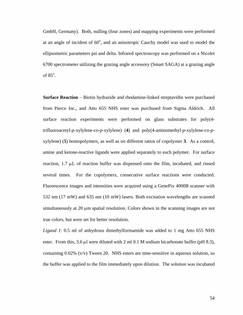
54
GmbH, Germany). Both, nulling (four zones) and mapping experiments were performed
at an angle of incident of 60o, and an anisotropic Cauchy model was used to model the
ellipsometric parameters psi and delta. Infrared spectroscopy was performed on a Nicolet
6700 spectrometer utilizing the grazing angle accessory (Smart SAGA) at a grazing angle
of 85o.
Surface Reaction – Biotin hydrazide and rhodamine-linked streptavidin were purchased
from Pierce Inc., and Atto 655 NHS ester was purchased from Sigma Aldrich. All
surface reaction experiments were performed on glass substrates for poly(4-
trifluoroacetyl-p-xylylene-co-p-xylylene) (4) and poly(4-aminomethyl-p-xylylene-co-p-
xylylene) (5) homopolymers, as well as on different ratios of copolymer 3. As a control,
amine and ketone-reactive ligands were applied separately to each polymer. For surface
reaction, 1.7 µL of reaction buffer was dispensed onto the film, incubated, and rinsed
several times. For the copolymers, consecutive surface reactions were conducted.
Fluorescence images and intensities were acquired using a GenePix 4000B scanner with
532 nm (17 mW) and 635 nm (10 mW) lasers. Both excitation wavelengths are scanned
simultaneously at 20 µm spatial resolution. Colors shown in the scanning images are not
true colors, but were set for better resolution.
Ligand 1: 0.5 ml of anhydrous dimethylformamide was added to 1 mg Atto 655 NHS
ester. From this, 3.6 µl were diluted with 2 ml 0.1 M sodium bicarbonate buffer (pH 8.3),
containing 0.02% (v/v) Tween 20. NHS esters are time-sensitive in aqueous solution, so
the buffer was applied to the film immediately upon dilution. The solution was incubated

55
O
CF3
Pyrolysis
O CF3
*
*
m
m+n
n
(3)
PolymerizationCH2
CH2
CH2
CH2
CH2
CH2
O
CF3
+
+ +
+
2
2
+
(1)
(2)
670 oC, 0.56 mbar 10 oC, 0.56 mbar
O
CF3
NH2
NH2
NH2
NH2
*
n
n
*
(5)
NH2O CF3
*
m
m
*
(4)
O
CF3
Pyrolysis
O CF3
*
*
m
m+n
n
(3)
PolymerizationCH2
CH2
CH2
CH2
CH2
CH2
O
CF3
+
+ +
+
2
2
+
(1)
(2)
670 oC, 0.56 mbar 10 oC, 0.56 mbar
O
CF3
NH2
NH2
NH2
NH2
*
n
n
*
(5)
NH2O CF3
*
m
m
*
(4) Figure 3.1. The multifunctional polymer (3) accessible by CVD copolymerization of [2.2]paracyclophanes (1) and (2); the structures of the individual polymers 4 and 5 are shown for comparison.
for 1 hour at room temperature, after which the surface was rinsed with ethanol for 5
minutes and with PBS/Tween solution for 30 minutes.
Ligand 2: Biotin hydrazide was diluted to 10 mM in phosphate buffered saline (PBS pH
7.4). The solution was gently heated and acid-catalyzed prior to surface application.
Incubation time lasted 5 to 7 minutes, which was followed by a wash of PBS containing
0.02% (v/v) Tween 20. The area was then applied with rhodamine-linked streptavidin
solution (0.075 mg/ml in PBS; 0.02% (v/v) Tween 20; 0.1% (w/v) bovine serum
albumin) for 10 minutes. Finally, the entire glass slide was immersed for 1 hour in a
PBS/Tween/BSA solution.
3.3 Results and Discussion
3.3.1 CVD Copolymerization
Prior to CVD co-polymerization, 4-trifluoroacetyl [2.2]paracyclophane (1) and 4-
aminomethyl [2.2]paracyclophane (2) had to be synthesized from commercially available
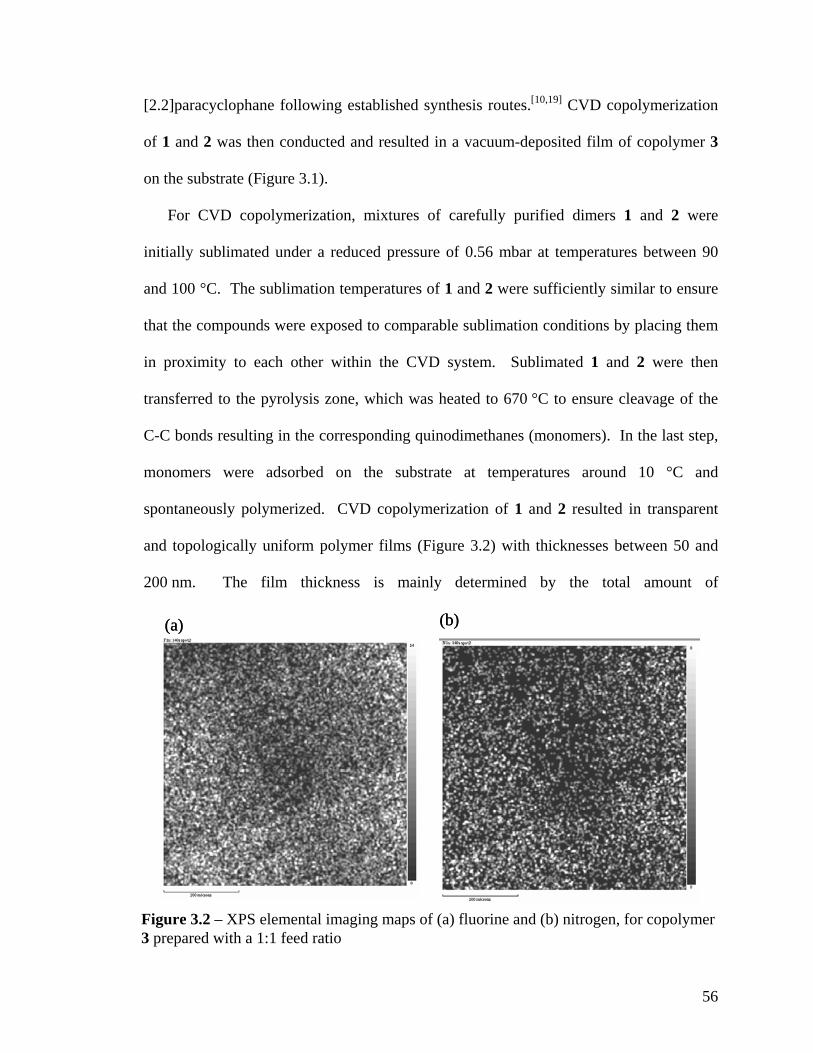
56
(b)(a) (b)(a)
Figure 3.2 – XPS elemental imaging maps of (a) fluorine and (b) nitrogen, for copolymer 3 prepared with a 1:1 feed ratio
[2.2]paracyclophane following established synthesis routes.[10,19] CVD copolymerization
of 1 and 2 was then conducted and resulted in a vacuum-deposited film of copolymer 3
on the substrate (Figure 3.1).
For CVD copolymerization, mixtures of carefully purified dimers 1 and 2 were
initially sublimated under a reduced pressure of 0.56 mbar at temperatures between 90
and 100 °C. The sublimation temperatures of 1 and 2 were sufficiently similar to ensure
that the compounds were exposed to comparable sublimation conditions by placing them
in proximity to each other within the CVD system. Sublimated 1 and 2 were then
transferred to the pyrolysis zone, which was heated to 670 °C to ensure cleavage of the
C-C bonds resulting in the corresponding quinodimethanes (monomers). In the last step,
monomers were adsorbed on the substrate at temperatures around 10 °C and
spontaneously polymerized. CVD copolymerization of 1 and 2 resulted in transparent
and topologically uniform polymer films (Figure 3.2) with thicknesses between 50 and
200 nm. The film thickness is mainly determined by the total amount of

57
[2.2]paracyclophanes used for polymerization. For instance, the thickness of a film
produced by the deposition of 20 mg of equimolar amounts of 1 and 2 was determined by
means of imaging ellipsometry to be (115 ± 15) nm. Moreover, the multi-functional
coatings showed excellent chemical stability in a dry air environment. No significant
change in composition or chemical behavior was found for samples stored in a dry air
atmosphere for several weeks as compared to freshly prepared samples. All copolymers
as well as the two individual polymers 4 and 5 remained intact after rinsing with standard
solvents, such as water, chloroform, acetone, and ethanol.
The elemental composition of the copolymer poly[4-aminomethyl-p-xylylene-co-4-
trifluoroacetyl-p-xylylene-co-p-xylylene] (3) was studied by X-ray photoelectron
spectroscopy (XPS). XPS is capable of detecting atomic composition within a depth of
about 10 nm.[20] The co-polymer 3 was compared to the individual polymers, poly[4-
trifluoroacetyl-p-xylylene-co-p-xylylene] (4) and poly[4-aminomethyl-p-xylylene-co-p-
xylylene] (5, see Table 3.1).
C–C C–N C=O π π* C–F BE/eV 285.0 286.8 288.4 291.2 292.9 Calculated/% (3) 89.2 3.6 3.6 – 3.6 Experimental/%a 89.5 3.1 3.3 4.3b 4.1 Calculated/% (4) 81.48 0 9.26 -- 9.26 Experimental/% 80.17 0 9.29 4.2 10.54 Calculated/% (5) 94.12 5.88 0 -- 0 Experimental/% 94.27 5.73 0 5.8 0 [a] Percentage of total without π π∗; applies to all experimental values [b] Actual value obtained; applies to all π π∗ values. Table 3.1. High-resolution C1s XPS results for poly[(4-aminomethyl-p-xylylene)-co-(4-trifluoroacetyl-p-xylylene)-co-p-xylylene] (3) prepared with a 1:1 feed ratio compared to the individual polymers 4 and 5.
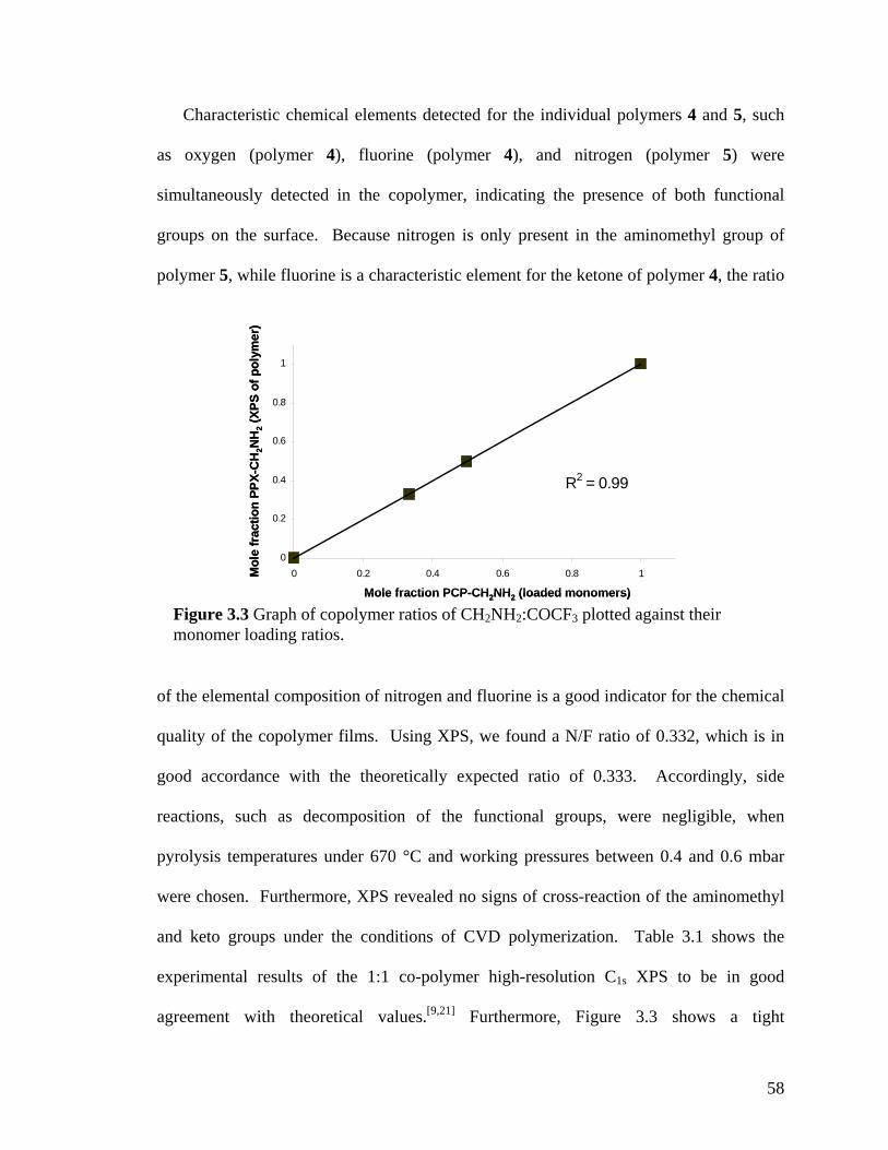
58
R2 = 0.99
0
0.2
0.4
0.6
0.8
1
0 0.2 0.4 0.6 0.8 1
Mole fraction PCP-CH2NH2 (loaded monomers)
Mol
e fr
actio
n PP
X-C
H2N
H2
(XPS
of p
olym
er)
R2 = 0.99
0
0.2
0.4
0.6
0.8
1
0 0.2 0.4 0.6 0.8 1
Mole fraction PCP-CH2NH2 (loaded monomers)
Mol
e fr
actio
n PP
X-C
H2N
H2
(XPS
of p
olym
er)
Figure 3.3 Graph of copolymer ratios of CH2NH2:COCF3 plotted against their monomer loading ratios.
Characteristic chemical elements detected for the individual polymers 4 and 5, such
as oxygen (polymer 4), fluorine (polymer 4), and nitrogen (polymer 5) were
simultaneously detected in the copolymer, indicating the presence of both functional
groups on the surface. Because nitrogen is only present in the aminomethyl group of
polymer 5, while fluorine is a characteristic element for the ketone of polymer 4, the ratio
of the elemental composition of nitrogen and fluorine is a good indicator for the chemical
quality of the copolymer films. Using XPS, we found a N/F ratio of 0.332, which is in
good accordance with the theoretically expected ratio of 0.333. Accordingly, side
reactions, such as decomposition of the functional groups, were negligible, when
pyrolysis temperatures under 670 °C and working pressures between 0.4 and 0.6 mbar
were chosen. Furthermore, XPS revealed no signs of cross-reaction of the aminomethyl
and keto groups under the conditions of CVD polymerization. Table 3.1 shows the
experimental results of the 1:1 co-polymer high-resolution C1s XPS to be in good
agreement with theoretical values.[9,21] Furthermore, Figure 3.3 shows a tight

59
mole T_CH2NH2 T_COCF3 total growth fraction CH2NH2 (oC) (oC) rate (A/s)
0 88.0 95.0 0.7 0.18 93.6 73.8 0.6 0.26 95.8 64.8 0.6 0.4 104.3 58.3 0.7 0.49 110.6 51 0.7 0.62 115.8 40.7 0.7 0.73 137.6 40 0.7 0.91 142 35 0.7
Table 3.2. XPS composition of co-polymer (PPX-CH2NH2/-COCF3), deposited using various monomer sublimation temperatures. Monomer loading ratio of 1:1 was used for all depositions.
correspondence between the loaded monomer ratio and the actual composition of the
copolymer as indicated by the N/F ratio measured by XPS. Copolymer composition can
also be correlated to the monomer sublimation rates, which were controlled by the
sublimation temperatures. Compositions were determined using XPS, and the
sublimation temperatures of both monomers were recorded in situ using a thermocouple.
Table 3.2 details the results of this study.
To further support the XPS data, we used grazing angle FTIR spectroscopy to assess
the structure of copolymers deposited onto a gold substrate. Figure 3.4 displays IR
spectra of polymer films made by co-polymerization of 1 and 2 using varying feed ratios.
The spectra are ranging from 100% of compound 2 (a) to 100% of compound 1 (g). All
spectra were normalized based on the C-H band intensity (2926.1 cm-1), because the C-H
group is present in each polymer. If the feed ratio changed, the peak intensities of side
groups were changed accordingly. Due to potential differences in film thickness, we
restrained ourselves to qualitative analysis only: The carbonyl stretches at 1715 cm-1
being characteristic for COCF3 groups were compared to the C-H band at 2926.1 cm-1.
The carbonyl stretch at 1715 cm-1 is absent in spectrum (a). For spectra (b) to (g), the

60
500
10
00
1500
20
00
2500
30
00
3500
40
00
Wav
enum
bers
(cm
-1)
1715
.7 (C
=O)
3361
, 330
1 (N
-H)
1227
, 120
2, 1
152
(C-F
)16
41.2
(N-H
)29
26, 2
860
(C-H
)
837.
897
6.9
(a)
(b)
(c)
(d)
(e)
(f)
(g)
500
10
00
1500
20
00
2500
30
00
3500
40
00
Wav
enum
bers
(cm
-1)
1715
.7 (C
=O)
3361
, 330
1 (N
-H)
1227
, 120
2, 1
152
(C-F
)16
41.2
(N-H
)29
26, 2
860
(C-H
)
837.
897
6.9
(a)
(b)
(c)
(d)
(e)
(f)
(g)
Fig
ure
3.4.
FTI
R sp
ectra
of (
3) w
ith v
aryi
ng m
olar
ratio
s of C
H2N
H2:C
OC
F 3. (
a) p
ure
CH
2NH
2 (b)
5:1
(c) 2
:1 (d
) 1:1
(e) 1
:2
(f) 1
:5 (g
) pur
e C
OC
F 3.

61
carbonyl stretch grows until maximum intensity is attained for spectrum (g). The same
trend can be observed for the C-F stretches at 1227, 1202, and 1152 cm-1. Similarly, the
signal at 976 cm-1 increases with increasing contribution of the ketone to become a strong
signal for the pure polymer 4. This band has been previously reported for similar
polymers.[22]
In many cases, homogeneous deposition of coatings is an important technological
requirement. The deposition chamber used in this study is large enough for temperature
gradients within the chamber and/or on the sample holder to form. Such differences, if
they exist, may impede accurate deposition of defined co-polymer ratios. To assess
potential inhomogeneities created during CVD co-polymerization due to temperature
differences, co-polymer PPX-CH2NH2/-COCF3 (1:1 monomer ratio) was deposited on 9
different samples, each located at various positions within the sample holder (Figure 3.5).
The experimental conditions were maintained as described for other CVD co-
polymerization procedures, with the exception that the sample holder was not rotated and
the substrate temperature was systematically varied. FTIR was used to obtain the ratio of
C-N to C=O bands, which served as an indicator of co-polymer ratios. For each
temperature, sample #2 (Figure 3.5a) was used as a reference; all sample peak ratios were
normalized by the peak ratio of sample #2. As shown in Figure 3.5b, average ratio of two
functional groups remained relatively constant across all deposition temperatures,
suggesting no significant compositional differences on the sample holder, even at
different substrate temperatures.
Once the fundamental concept of CVD co-polymerization of [2.2]paracyclophanes
with different functional groups was established, the structural properties of the resulting
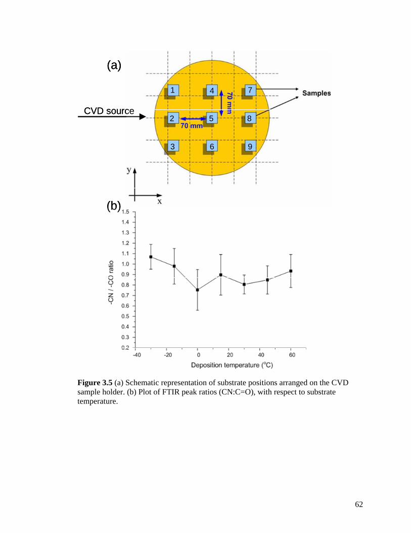
62
(a)
(b)
1
2
3
4
5
6
7
8
9
CVD source
(a)
(b)
1
2
3
4
5
6
7
8
9
CVD source
Figure 3.5 (a) Schematic representation of substrate positions arranged on the CVD sample holder. (b) Plot of FTIR peak ratios (CN:C=O), with respect to substrate temperature.

63
co-polymers needed to be elucidated in further details. In principle, CVD co-
polymerization could result in a true co-polymer - with properties distinct from individual
polymers 4 and 5 - or could result in a layered blend of the two polymers.
We used X-ray diffraction (XRD) measurements of thin CVD films before and after
annealing to address this question.[23] This approach takes advantage of the fact, that
poly(p-xylylenes) are often semi-crystalline polymers with characteristic features in the
XRD spectra.[24,25] Since XRD data for polymers 4 and 5 had not yet been reported, we
studied the individual CVD polymers first. Prior to annealing, no diffraction patterns
were obtained for either 4 or 5, indicating that both films were largely amorphous in the
as-deposited state.[26]
After annealing for 14 hrs at 120 ºC, however, the trifluoroacetyl-functionalized
polymer 4 showed characteristic diffraction patterns, which likely correspond to (020)
and (110) planes, and a d-spacing greater than that reported for the monoclinic poly(p-
xylylene).[27] In contrast, the aminomethyl-functionalized polymer 5 remained
amorphous. Figure 3.6 compares diffraction patterns before and after annealing for the
individual polymers 4 and 5 and the co-polymers. Exposing the films to a high-
temperature environment allows for realignment of functional groups to form crystalline
domains.[20] Next, we assessed the structural properties of polymer 3 made by co-
polymerization of an equimolar feed ratio of 1 and 2. Based on the FTIR study, we
expect this co-polymer to contain both components in about the same ratio. If the co-
polymerization would result in a layered blend of individual polymers 4 and 5, the
resulting diffraction pattern should essentially be the superposition of the diffraction
patterns of the individual polymers. If however the CVD co-polymerization results in a
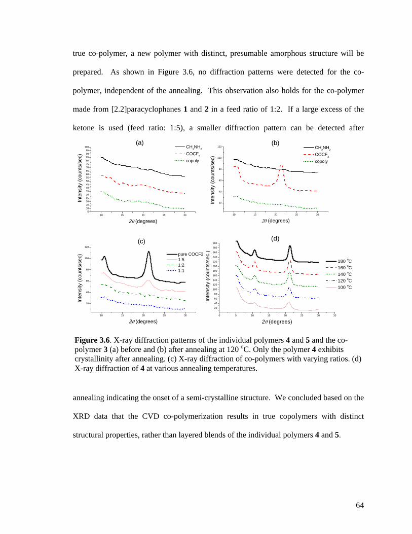
64
10 15 20 25 30
20
40
60
80
100
120
Inte
nsity
(cou
nts/
sec)
2θ (degrees)
CH2NH2
COCF3
copoly
(b)
10 15 20 25 30
20
40
60
80
100
120
Inte
nsity
(cou
nts/
sec)
2θ (degrees)
pure COCF3 1:5 1:2 1:1
(c)
0 5 10 15 20 25 30 35
20
40
60
80
100
120
140
160
180
200
220
240
260
280
300
Inte
nsity
(cou
nts/
sec.
)
2θ (degrees)
180 oC 160 oC 140 oC 120 oC 100 oC
(d)
10 15 20 25 305
101520253035404550556065707580859095
100
Inte
nsity
(cou
nts/
sec)
2θ (degrees)
CH2NH2
COCF3
copoly
(a)
Figure 3.6. X-ray diffraction patterns of the individual polymers 4 and 5 and the co-polymer 3 (a) before and (b) after annealing at 120 oC. Only the polymer 4 exhibits crystallinity after annealing. (c) X-ray diffraction of co-polymers with varying ratios. (d) X-ray diffraction of 4 at various annealing temperatures.
true co-polymer, a new polymer with distinct, presumable amorphous structure will be
prepared. As shown in Figure 3.6, no diffraction patterns were detected for the co-
polymer, independent of the annealing. This observation also holds for the co-polymer
made from [2.2]paracyclophanes 1 and 2 in a feed ratio of 1:2. If a large excess of the
ketone is used (feed ratio: 1:5), a smaller diffraction pattern can be detected after
annealing indicating the onset of a semi-crystalline structure. We concluded based on the
XRD data that the CVD co-polymerization results in true copolymers with distinct
structural properties, rather than layered blends of the individual polymers 4 and 5.

65
CVDCo-polymerization
Ligandreactions
Amine-reactive
Ketone-reactive
O
O
R1
O
NH
NH2
Co-polymer
CF3O CF3O
Polymer (3)
NH2
CH2
NH2
CH2
O
HN
CH2
O
HN
CH2
CF3N
O
NH
CF3N
O
NH
Polymer (3)
CVDCo-polymerization
Ligandreactions
Amine-reactive
Ketone-reactive
O
O
R1
O
NH
NH2
Co-polymer
CF3O CF3O
Polymer (3)
NH2
CH2
NH2
CH2
CF3O CF3O
Polymer (3)
NH2
CH2
NH2
CH2
O
HN
CH2
O
HN
CH2
CF3N
O
NH
CF3N
O
NH
Polymer (3)
O
HN
CH2
O
HN
CH2
CF3N
O
NH
CF3N
O
NH
Polymer (3)
Figure 3.7. Schematic outlining the selective reactivity of the multivalent surface. The activated ester will only react with the aminomethyl group, while the hydrazide group shows selective reactivity towards ketones.
3.3.2 Surface Reactions
Finally, we verified that both functional groups contained in co-polymer 3 are
available for further surface modification. The availability of the functional groups for
further surface reaction is essential for immobilization of two different types of
(bio)molecules. In a proof of concept experiment using the approach shown in Figure
3.7, the copolymer surface (3) was reacted with two fluorescent dyes, which exhibited
orthogonal reactivity. The purpose of this experiment was to assess whether or not each
functional group remains active and able to specifically react with the assigned ligands.
Fluorescence scanning was used to examine the presence of surface-bound ligands.
Figure 3.8 shows the results of the surface reaction of polymer 3 with Atto 655 as well as
biotin-streptavidin. To avoid reaction of the Atto 655 ligand with the amino groups of

66
1
0.0 0.2 0.4 0.6 0.8 1.00
10
20
30
40
50
60
70A
vg. f
luor
esce
nce
inte
nsity
(nor
mal
ized
)
x(2)
1 3
2
Figure 3.8. Fluorescence intensities detected on the co-polymers versus x(2), the relative feed concentration of [2.2]paracyclophane 2 used for CVD copolymerization. The trends demonstrate ligand immobilization occurs in controlled ratios as a function of increasing relative ratio of the [2.2]paracyclophanes. Inlet: Fluorescence micrograph of areas that were reacted with biotin ligand (1), Atto 655 ligand (2), or both (3).
strepdavidin, a conceutive immobilization scheme was employed: The Atto 655 ligand
was immobilized first followed by the biotin ligand.
We found Atto 655 to bind strongly to the aminomethyl-containing polymer 5. In
contrast, only negligible amounts of Atto bound to polymer 4. When reacting the two
individual polymers 4 and 5 with the second ligand, a biotin hydrazide derivative, the
biotin ligand was found to bind strongly to polymer 4, but not to 5. Fluorescence-labeled
streptavidin, a specific binding partner of biotin, was than used to visualize the biotin
ligands and confirmed selective binding to biotin-modified coating 4. In contrast,
streptavidin applied to the polymer 4 that was not modified with the biotin ligand did not
mm

67
give any appreciable fluorescence signal. When performing the same procedure on co-
polymer 3, both fluorescence signals were observed simultaneously (Figure 3.8). By
varying the feed ratios of [2.2]paracyclophanes 1 and 2 in the CVD polymerization, the
relative ratio of ligands bound to the surface was varied. The relative increase of starting
material 2 resulted in surfaces with increased amounts of Atto-labled ligands (red color),
while a relative increase of compound 1 used for CVD polymerization resulted in an
increased fluorescence signal indicating more stepdavidin/biotin pair bound to the
surface. Based on the FTIR spectra (Figure 3.4), these trends can be explained by the
controlled variation of binding sides available for the two ligands on the surface, which
corresponds to the feed ratio of staring materials used during CVD copolymerization. For
the 1:1 ratio, the fluorescence micrographs of different reaction areas are shown in the
inlet of Figure 3.8. Area 1 shows copolymer 3, which reacted only to the biotin ligand
(green color), while area 2 is characterized by red fluorescence, which is due to surface-
immobilization of the Atto-labeled ligand. Where both ligands were allowed to react with
the copolymer 3 (area 3), yellow color is observed indicating the parallel immobilization
of the two ligands.
3.4 Conclusions
The herein proposed concept of CVD polymerization of functionalized
[2.2]paracyclophanes establishes a general, but simple protocol for preparation of multi-
reactive polymer films. Applicability of the reactive coating to various substrates, such
as polymers, metals, or composites generates a fairly universal platform without relying
on broad chemical alteration of the bulk material.[28-30] Although multipotent biointerfaces
68
could in principle be prepared by simultaneously immobilizing mixtures of two different
biomolecules through the same functional groups, the exploration of reactive coatings
with two orthogonal functional groups bears several potential advantages: (1) Surface
ratios can be controlled with high precision, because the ligand immobilization reactions
can be conducted independently. (2) Substantially different biomolecules can be co-
immobilized, even so their transport to the surface is substantially different. (3) The
ability to immobilize biomolecules in a sequence allows for combinations of
biomolecules that would otherwise cross-react with each other. For applications, where
substantially different biomolecules need to be immobilized in precisely defined ratios,
the CVD co-polymerization may provide a simple access route. Moreover, this study
presents a first step towards the establishment of a modular coating design, where the
properties of a coating can simply be dialed-in by selecting the right combination of
building blocks for CVD polymerization. Copolymer compositions are directly related to
the monomer sublimation temperatures, where changing the sublimation temperature(s)
affected relative sublimation rates. Such a modular surface design may be of great value
for future biomedical devices, high-throughput screening platforms, microfluidic analysis
devices, or diagnostic platforms.

69
References
[1] C.S. Chen, J.L. Alonso, E. Ostuni, G.M. Whitesides, D.E. Ingber, Biochem. Biophys.
Res. Comm. 2003, 307, 355.
[2] H, Tani, K. Maehana, T. Kamidate, Anal. Chem. 2004, 76, 6693.
[3] K. Kato, H. Sato, H. Iwata, Langmuir 2005, 21, 7071.
[4] X. Liu, Y. Won, P. X. Ma, J. Biomed. Mater. Res. 2005, 74A, 84.
[5] M.H. Ho, D.M. Wang, H.J. Hsieh, H.C. Liu, T.Y. Hsien, J.Y. Lai, L.T. Hou,
Biomaterials 2005, 26, 3197.
[6] D.R. Reyes, D. Iossifidis, P.A. Auroux, A. Manz, Anal. Chem. 2002, 74, 2623.
[7] P.A. Auroux, D. Iossifidis, D.R. Reyes, A. Manz, Anal. Chem. 2002 ,74, 2637.
[8] D.G. Castner, B.D. Ratner, Surface Science 2002, 500, 28.
[9] J. Lahann, R. Langer, Macromolecules 2002, 35, 4380.
[10] J. Lahann, D. Klee, H. Höcker, Macromol. Rapid Commun. 1998, 19, 441.
[11] J. Lahann, R. Langer, Macromol. Rapid Commun. 2001, 22, 968.
[12] J. Lahann, H. Hocker, R. Langer, Angew. Chem. Int. Ed. 2001, 40, 726.
[13] J. Lahann, I.S. Choi, J. Lee, K. Jensen, R. Langer, Angew. Chem., Int. Ed. 2001, 40,
3166.
[14] J. Lahann, M. Balcells, T. Rodon, J. Lee, I. Choi, K. Jensen, R. Langer, Langmuir
2002, 18, 3632.
[15] H. Nandivada, H.Y. Chen, J. Lahann, Macromol. Rapid Commun. 2005, 26, 1794.
[16] K. Schürmann, J. Lahann, J. Meyer, H. Klosterhalfen, D. Vorwerk, D. Klee, R.W.
Günther, Radiology 2004, 230, 151.
[17] A. Greiner, Trends Polym. Sci. 1997, 5, 12.

70
[18] D. Klee, N. Weiss, J. Lahann, “Vapor-Based Polymerization Of Functionalized
[2.2]Paracyclophanes: A Unique Approach Towards Surface-Engineered
Microenvironments” in Paracyclophanes, H. Hopf (ed.), VCH Weinheim, 2004.
[19] V.I. Rozenberg, T.I. Danilova, E.V. Sergeeva, I.A. Shouklov, Z.A. Starikova, H.
Hopf, K. Kuhlein, Eur. J. Org. Chem. 2003, 432.
[20] B.D. Ratner, A.S. Hoffman, F.J. Schoen, J.E. Lemons, “Biomaterials Science”.
1996, Elsevier Science, USA.
[21] D. Briggs, G. Beamson, Anal. Chem. 1992, 64, 1729.
[22] C.H. Cheng, E.M. Pearch, J. Poly. Sci: Poly. Chem. Ed. 1980, 18, 1883.
[23] B.D. Cullity, S.R. Stock, “Elements of X-ray Diffraction.” 3rd Ed. 2001, Prentice-
Hall, Inc.
[24] S. Isoda, M. Tsuji, M. Ohara, A. Kawaguchi, Polymer 1983, 24, 1155.
[25] W.D. Niegisch, J.Appl. Phys. 1966, 37, 4001.
[26] All films were deposited at 10 ºC.
[27] J.J. Senkevich, S.B. Desu, V. Simkovic, Polymer 1999, 41, 2379.
[28] K.-Y. Suh, R. Langer, J. Lahann, Adv. Mater. 2004, 16, 1401.
[29] H.Y. Chen, J. Lahann, Anal. Chem. 2005, 77, 6909.
[30] J. Lahann, M. Balcells, H. Lu, T. Rodon, K.F. Jensen, R. Langer, Anal. Chem. 2003,
75, 2117.

71
CHAPTER 4
PRELIMINARY BIOCOMPATIBILITY OF COPOLYMER COATINGS
The materials in this chapter have been adapted with minor modifications from the
following published article: Y. Elkasabi, M. Yoshida, H. Nandivada, H.Y. Chen, J.
Lahann, Macromolecular Rapid Communications 2008, 29, 855-870.
4.1 Background and Motivations
The fields of materials engineering and biointerface science are witnessing an
increasing merger of concepts and applications.[1] While these two fields remained quite
exclusive from each other only 40 to 50 years ago,[2] recent progress in biotechnological
and medical applications has expedited and necessitated their fusion. Examples include,
but are not limited to, the study of cell/matrix interactions,[3] micro total analytical
systems (µTAS),[4] and scaffolds for tissue engineering.[5] More specifically, these
applications require materials with sufficient mechanical integrity, while providing
adequate contact properties within biologically-relevant environments. To date, many of
the currently employed biomaterials still induce unfavorable responses, such as chronic
inflammation[6] or blood coagulation.[7,8] One way of addressing these shortcomings is
controlled surface modification, because interactions of the biomaterial surface with
proteins and cells are among the key factors that govern these biological responses.[8,9]
Methods such as plasma polymerization,[10] self-assembly of monolayers,[11] and spray
coating[12] have been extensively used in the past to design materials which exhibit
72
defined surface chemistries; however, many of these methods fall short when devices
with materials that diverge from well-defined model systems and non-planar geometry
are used.[13] Although widely used, solution-based surface modification methods bear the
risk of introducing coating non-uniformities and impurities.[14]
In this chapter, we focus on the synthesis and characterization of carbonyl-
functionalized copolymers and elucidate important aspects of these coatings for future
biomedical applications. We also assessed preliminary biocompatibility of these coatings
in short-term experiments, using human umbilical vein endothelial cells and 3T3 murine
fibroblasts.
4.2 Experimental Methods
Monomer Synthesis 4-Aminomethyl-[2.2]paracyclophane was purchased from Uniglobe
Kisco, Inc. (White Plains, NY). 4-Amino-[2.2]paracyclophane was synthesized from
[2.2]paracyclophane using an established synthesis route.[15] All carbonyl-functionalized
PCPs were synthesized by Friedel-Crafts acylation of commercially available
[2.2]paracyclophane (Uniglobe Kisco) as described previously.[16] All synthesized
monomers were purified by column chromatography prior to CVD polymerization, and
characterized by nuclear magnetic resonance spectroscopy (NMR), mass spectrometry
(MS) and Fourier Transform infrared spectroscopy (FTIR).
CVD Polymerization All polymer coatings were synthesized using a custom-built CVD
system.[17] For CVD polymerization, a total of 20-30 mg of either one or two different

73
functionalized [2.2]paracyclophane(s) was used. For co-polymerization, the molar ratios
of amino-functionalized (-NH2, -CH2NH2) and carbonyl-functionalized (-COC6H5, -
COC2H5, -COC2F5, -COCF3) PCPs (refer to Scheme 4.2) were varied to yield a
previously specified target ratio of functional groups of the CVD coatings. To account
for differences in the sublimation temperatures of different PCPs, charges of starting
material were loaded individually into magnetically movable glass dishes. For CVD co-
polymerization, the working pressure was 0.28 Torr and sublimation temperatures varied
between 90 and 100 oC. For different functionalized PCPs, the pyrolysis temperature
changed with various functionalities. PCP-COC6H5 was activated at a pyrolysis
temperature of 800°C in order for polymerization to occur, whereas all other monomers
were cleaved at 670°C. Preparation of co-polymers (-COC6H5/-NH2 and - COC6H5/-
CH2NH2 required a pyrolysis temperature of 730°C. All other copolymers utilized a
pyrolysis temperature of 670°C. Silicon, gold, stainless steel, or glass substrates were
placed on a cooled sample holder (15°C; unless stated otherwise) for polymer deposition.
Sample holder was rotated to ensured more uniform film deposition. For co-
polymerization of varying molar feed ratios within one subgroup, all reaction conditions
were maintained with the exception of the adjusted ratio of the two starting materials.
Surface Characterization X-ray photoelectron spectroscopy (XPS) data were recorded
on an Axis Ultra X-ray photoelectron spectrometer (Kratos Analyticals, UK) equipped
with a monochromatized AlKα X-ray source. All spectra were calibrated with respect to
the non-functionalized aliphatic carbon with a binding energy of 285.0 eV. Coating
thicknesses were recorded using EP3-SW imaging ellipsometry (Nanofilm Technologie
74
GmbH, Germany) at a wavelength of 532 nm. Both nulling (four zones) and mapping
experiments were performed at an angle of incident of 60o, and an anisotropic Cauchy
model was used to model the ellipsometric parameters psi and delta. FTIR was
performed on a Nicolet 6700 spectrometer utilizing the grazing angle accessory (Smart
SAGA, Thermo) at a grazing angle of 85o.
X-ray Diffraction (XRD) To assess the crystallinity of functionalized PPX films, silicon
substrates coated with the polymer of interest were examined by wide-angle XRD, using
a Rigaku 12 kW high intensity rotary anode generator. All CVD films were examined
both as deposited and after annealing. Prior to analysis, the polymer films were annealed
for 14 hrs in an oven at a temperature of 120oC.
Enzyme Linked Immunosorbent Assay (ELISA) Nunc 96 well plates and CVD-coated
stainless steel disks placed in 24 well plates were coated with varying concentrations of
human fibrinogen (Calbiochem) diluted in Dulbecco’s PBS overnight at 4oC. Surfaces
were blocked (1% BSA in Dulbecco’s PBS 25oC, 1 hr), incubated with primary antibody
(rabbit anti-human fibrinogen, Calbiochem, San Diego, CA; 1:8,000) in wash buffer
(0.5% Tween20 in Dulbecco’s PBS) for 1 hr at 25oC, washed, and incubated with
secondary antibody (goat anti-rabbit IgG H&L chain, peroxidase conjugate, Calbiochem,
1:10,000) in wash buffer for 1 hr at 25oC. Upon washing, the surfaces were incubated
with 2,2'-azino-bis-(3-ethylbenzthiazoline-6-sulfonic acid) (ABTS) for 20 min at 25oC.
The enzymatic reaction was terminated with a 0.5M H2SO4 stop solution and analyzed by
absorbance measurement at 405 nm.

75
Growth of HUVECs and NIH3T3s on CVD-coated surfaces Human umbilical vein
endothelial cells (HUVECs) (Cambrex, Walkersville, MD) or murine fibroblasts (NIH
3T3s) (ATCC, Manassas, VA) were cultured in tissue culture-treated polystyrene (TCPS)
flasks (Corning, Lowell, MA), maintained at 37°C in a humidified atmosphere of 5%
CO2, and media replaced every other day until ~80% confluency was reached.
Functionalized PPX polymers and co-polymers were deposited on 18 mm, No. 1
glass cover slips. Polymer-coated cover slips were placed in sterile 12-well plates and
incubated in Endothelial Growth Medium (Cambrex) prior to addition of cells. HUVECs
were suspended at a density of 1x10⁵/ml, and added at 1 ml/well. Phase contrast
micrographs were taken at 2 hrs and 24 hrs post-seeding. At 24 hrs post-seeding,
substrates with adherent cells were processed for immunocytochemistry. Samples were
fixed and permeabilized (4% paraformaldehyde, 0.5% TritonX-100 in Dulbecco’s PBS)
for 15 min, blocked (1% BSA) for 30 min, and stained with a primary antibody (1:400
anti-vinculin, Sigma, 1:400). Upon washing, cells were blocked (5% normal goat serum,
(Zymed, Carlsbad, CA)) then stained with secondary antibody (Alexa Fluor 488-
conjugated goat anti-mouse IgG1 (Invitrogen, Carlsbad, CA)), followed by rhodamine-
conjugated phalloidin (Invitrogen). Finally, samples were mounted with Prolong Gold
with DAPI (Invitrogen) for analysis by confocal microscopy.
NIH3T3s were grown on CVD-coated stainless steel disks or PVC films at a
density of 7.5x10⁴/ml in 24 well plates. All substrates were UV-sterilized for 30 min
prior to addition of cells. After 24 hrs in culture, substrates were fixed, permeabilized,
then stained with rhodamine-conjugated phalloidin and Hoechst 33342 (Invitrogen).

76
Substrates were mounted on cover slips with Prolong Gold, and imaged by confocal
microscopy. All fluorescently-labeled cells were visualized using Zeiss LSM 510
confocal microscope at the Microscopy & Image Analysis Laboratory of the University
of Michigan.
Glucose 6-phosphatase Dehydrogenase (G6PD) Release Upon culturing NIH3T3 cells
on bare or CVD-coated stainless steel disks for 24 hrs, cell culture media was collected
and cleared by centrifugation at 1200 rpm for 5 min. Growth media alone or media from
cells grown on TCPS, or that from lysed cells (0.1% TritonX-100 for 5 min) were used as
controls. Cleared media were analyzed for G6PD content by Vybrant Cytotoxicity Assay
Kit (Molecular Probes) per manufacturer’s directions. Fluorescence values (ex/em:
544/590) were recorded every 5 min after addition of 2x resazurin reaction mixture to the
well at 37°C. For statistical analysis, results from all surfaces were compared to those of
live cells grown on TCPS, using p<0.01.
Statistical Analysis Statistical analysis was performed using a general linear model
ANOVA with Minitab software (Version 13.20, Minitab, State College, PA, USA).
Unless otherwise indicated, p-values of 0.05 were considered significant. Experiments
were repeated as indicated.
NMR Studies Carbonyl-functionalized p-xylenes were synthesized following an
approach slightly modified from the synthetic procedures described for the corresponding
PCPs. Model reactions of the carbonyl groups with hexanoic hydrazide were performed
77
in an NMR tube and sequence of 1H NMR (Varian Inova, 400 MHz) spectra was
collected in real-time. Prior to starting the reaction, a base 1H NMR spectrum was taken
as a reference. A slight excess of hexanoic hydrazide (1.1 equivalents) was dissolved in
deuterated ethyl alcohol, and the functionalized p-xylene was added. Next, acetic acid
was added to initiate the reaction, and data acquisition was started immediately after the
sample was placed in the NMR spectrometer. NMR spectra were acquired every 7
minutes for two hours, and a final measurement was taken after 12 hrs.
r-Hirudin Immobilization and Binding Assay. CVD-coated surfaces were incubated
with hexamethylene diisocyanate (HDI) (1:10 w/w in absolute diethyl ether) for 24 hrs in
argon atmosphere. The surfaces were then washed via Soxhlet extraction in absolute
diethyl ether for 6 hrs and dried under vacuum. Hirudin was immobilized by incubating
the surfaces with an N-terminal protected hirudin (500 nmol/ml in water) at 4°C for 24
hrs.[18] The surfaces were washed extensively using wash buffer (PBS containing 0.1%
Tween-20). The protecting group was cleaved by exposing the surface to piperidine
solution (10% in deionized (DI) water) at 0°C for 3 hrs, and substrates were washed
rigorously.
Hirudin binding was measured via an amidolytic assay (chromogenic assay) for
thrombin. The surfaces were incubated with thrombin solution (20 U/ml in PBS, pH 7.4,
Sigma-Aldrich, MO) for 30 min at 25°C, to which thrombin-active chromogenic substrate
(S-2238, 1 mmol/L in DI-water; DiaPharma Group Inc., OH) was added. The reaction
was stopped after 120 s with acetic acid (20 %), and the resulting colored solution was
transferred to cuvettes for UV absorption reading at 405 nm.
78
Heparin Immobilization and Binding Assay. CVD-coated substrates were incubated
with a 500 mM solution of adipic acid dihydrazide (Sigma-Aldrich, MO) in PBS for 24 h.
The substrates were then washed with wash buffer (PBS with 0.1% Tween20). These
hydrazide-functionalized substrates were immersed in heparin solution (1 mg/ml in
water, Sigma-Aldrich, MO) overnight at 50°C, washed with the wash buffer and finally
rinsed with water. To quantify heparin immobilization, 1 ml of Toluidine blue (0.0005%,
Sigma-Aldrich, MO) was placed with the heparin-modified surface and shaken
vigorously, to which 1 mL of n-hexane was added. After the organic layer (containing the
heparin-toluidine blue complex) was removed, the absorbance of the aqueous layer was
measured by UV spectrophotometry at 631nm.
4.3 Results and Discussion
4.3.1 Mono-Functionalized CVD Coatings
CVD-based PPXs offer a high degree of flexibility for functional groups that can
be introduced and therefore provide a very versatile chemical modification platform.
Such a strategy, however, requires synthesis of the appropriate PCPs and subsequent
vapor deposition of well-defined reactive coatings (Scheme 4.1), while maintaining the
integrity of the functional groups under the conditions of CVD polymerization. Among
the many reactive coatings that have been synthesized,[19] carbonyl-functionalized
polymers are of particular interest because of their favorable deposition properties and
their selectivity towards hydrazide-functionalized ligands.[20] When conducting CVD
polymerization of functionalized PCPs (-COC6H5, -COC2H5, -COC2F5, -COCF3),

79
Sc
hem
e 4.
1. (a
) Mec
hani
sm fo
r the
CV
D p
olym
eriz
atio
n of
car
bony
l-fun
ctio
naliz
ed P
CPs
to p
rodu
ce c
orre
spon
ding
PPX
s.
(b) S
chem
atic
dia
gram
of C
VD
pro
cess
. (c)
CV
D p
roce
ss c
ondi
tions
requ
ired
for P
PX d
epos
ition
.

80
transparent polymer films with excellent adhesion were obtained for silicon, gold,
stainless steel, and glass substrates. While the substrates used in this study were flat, we
have recently demonstrated that the CVD process is also amenable to the coating of
microspheres.[21] In addition, a range of complex patterns can be created using masking
techniques during CVD polymerization.[22] FTIR spectra of the polymers are shown in
Figure 4.1 and correspond well with the expected polymer structures.[23,24] Strong
carbonyl stretches were present in the range of 1720 – 1660 cm-1 in all spectra.
Characteristic C-H stretches which are due to aromatic hydrogen atoms were present
between 3050 – 2910 cm-1. In addition, the spectrum of PPX-COC2H5 revealed a higher
intensity band at 2930 cm-1, indicative of aliphatic hydrogen atoms. Strong FTIR bands
between 1204 and 1170 cm-1 are due to the fluorinated alkyl groups present in polymers
PPX-COC2F5 and PPX-COCF3. Collectively, the FTIR spectra shown in Figure 4.1
confirm the expected structures of carbonyl-functionalized polymers.
It has been previously observed that PPX derivatives with different functional
groups can either be semi-crystalline or amorphous.[25,26] In fact, even subtle differences
in the side group structure can influence the crystallinity of the polymer films. Therefore,
XRD was used to assess the differences amongst the four different carbonyl-
functionalized polymers, and the results were compared to unfunctionalized PPX
(parylene N). Upon deposition, XRD spectra of all polymers except for the
unfunctionalized PPX were void of any detectable signals indicating that these polymers
were amorphous (data not shown). After annealing at 120oC for 14 hrs, however, the
fluoroalkyl-containing polymers (PPX-COC2F5 and PPX-COCF3) underwent significant
chain remodeling as indicated by the appearance of sharp signals at 10.7o and 21.2o

81
500
10
00
1500
20
00
2500
30
00
3500
40
00
Wav
enum
bers
(cm
-1)
1660
.916
00.0
(a)
(b)
(c)
(d)
1708
.716
82.6
2930
.4
1708
.8
1717
.412
04.4
1169
.6
2917
.430
47.8
CO
C6H
5
CO
C2H
5
CO
C2F
5
CO
CF 3
500
10
00
1500
20
00
2500
30
00
3500
40
00
Wav
enum
bers
(cm
-1)
1660
.916
00.0
(a)
(b)
(c)
(d)
1708
.716
82.6
2930
.4
1708
.8
1717
.412
04.4
1169
.6
2917
.430
47.8
500
10
00
1500
20
00
2500
30
00
3500
40
00
Wav
enum
bers
(cm
-1)
500
10
00
1500
20
00
2500
30
00
3500
40
00
Wav
enum
bers
(cm
-1)
1660
.916
00.0
(a)
(b)
(c)
(d)
1708
.716
82.6
2930
.4
1708
.8
1717
.412
04.4
1169
.6
2917
.430
47.8
CO
C6H
5
CO
C2H
5
CO
C2F
5
CO
CF 3
Fi
gure
4.1
FTI
R sp
ectra
of P
PX p
olym
ers c
onta
inin
g th
e fo
llow
ing
func
tiona
l mod
ifica
tions
: (a)
CO
C6H
5, (b
) CO
C2H
5,(c)
C
OC
2F5,
and
(d) C
OC
F 3.
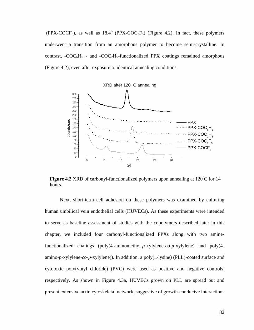
82
5 10 15 20 25 300
20
40
60
80
100
120
140
160
180
200
220
240
260
280
300
coun
ts/s
ec
2θ
PPX PPX-COC6H5
PPX-COC2H5
PPX-COC2F5
PPX-COCF3
XRD after 120 oC annealing
Figure 4.2 XRD of carbonyl-functionalized polymers upon annealing at 120°C for 14 hours.
(PPX-COCF3), as well as 18.4o (PPX-COC2F5) (Figure 4.2). In fact, these polymers
underwent a transition from an amorphous polymer to become semi-crystalline. In
contrast, -COC6H5 - and -COC2H5-functionalized PPX coatings remained amorphous
(Figure 4.2), even after exposure to identical annealing conditions.
Next, short-term cell adhesion on these polymers was examined by culturing
human umbilical vein endothelial cells (HUVECs). As these experiments were intended
to serve as baseline assessment of studies with the copolymers described later in this
chapter, we included four carbonyl-functionalized PPXs along with two amine-
functionalized coatings (poly(4-aminomethyl-p-xylylene-co-p-xylylene) and poly(4-
amino-p-xylylene-co-p-xylylene)). In addition, a poly(L-lysine) (PLL)-coated surface and
cytotoxic poly(vinyl chloride) (PVC) were used as positive and negative controls,
respectively. As shown in Figure 4.3a, HUVECs grown on PLL are spread out and
present extensive actin cytoskeletal network, suggestive of growth-conducive interactions
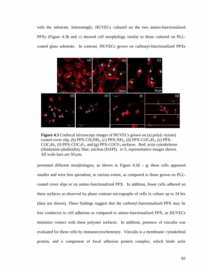
83
(g)(f)(e)
(a)
(d)
(c)(b)
(g)(f)(e)
(a)
(d)
(c)(b)
Figure 4.3 Confocal microscopy images of HUVECs grown on (a) poly(L-lysine) coated cover slip, (b) PPX-CH2NH2, (c) PPX-NH2, (d) PPX-COC6H5, (e) PPX-COC2H5, (f) PPX-COC2F5, and (g) PPX-COCF3 surfaces. Red: actin cytoskeleton (rhodamine-phalloidin), blue: nucleus (DAPI). n=3, representative images shown. All scale bars are 50 µm.
with the substrate. Interestingly, HUVECs cultured on the two amino-functionalized
PPXs (Figure 4.3b and c) showed cell morphology similar to those cultured on PLL-
coated glass substrate. In contrast, HUVECs grown on carbonyl-functionalized PPXs
presented different morphologies, as shown in Figure 4.3d – g; these cells appeared
smaller and were less spreadout, to various extent, as compared to those grown on PLL-
coated cover slips or on amino-functionalized PPX. In addition, fewer cells adhered on
these surfaces as observed by phase contrast micrographs of cells in culture up to 24 hrs
(data not shown). These findings suggest that the carbonyl-functionalized PPX may be
less conducive to cell adhesion as compared to amino-functionalized PPX, as HUVECs
minimize contact with these polymer surfaces. In addition, presence of vinculin was
evaluated for these cells by immunocytochemistry. Vinculin is a membrane/ cytoskeletal
protein, and a component of focal adhesion protein complex, which binds actin

84
cytoskeleton to link cells to its substrate via adhesion molecules.[27] Immunostaining
revealed increased numbers of punctuate vinculin staining on cells cultured on PLL- and
amino-functionalized PPX-coated surfaces relative to those cultured on carbonyl-
functionalized PPX coatings (data not shown). These results corroborate the findings of
more spreadout morphology of cells on PLL and amino-functionalized PPX surfaces in
that cell adhesion on these substrates is likely stronger than that of cells on carbonyl-
functionalized PPX. Together, results from this preliminary study suggest that differences
in the functional side groups of carbonyl-functionalized PPXs can result in polymer
coatings, with a wide range of different biological responses.
4.3.2 Multi-Functionalized CVD Coatings
Studies described thus far evaluated surfaces coated with a single type of PPX. In
next set of experiments, multifunctional coatings which simultaneously present multiple
chemical functional groups on the surfaces, were prepared by copolymerizing an amino-
functionalized PCP (-NH2 or -CH2NH2) with a carbonyl-functionalized PCP (-COC6H5,
-COC2H5, -COC2F5, or -COCF3), as outlined in Scheme 4.2. In these experiments, the
relative ratio of amino- versus carbonyl- groups was varied by altering the ratio of
starting amounts of different PCPs used for CVD polymerization. For a given copolymer
combination, all other process parameters, including total amount of starting materials,
pressure, and sublimation, pyrolysis, and deposition temperatures were kept constant.
By adjusting the ratio of monomers loaded into the CVD sublimation zone,
different molar ratios were prepared for each polymer combination, resulting in a variety
of co-polymers. For this approach to be successful, special care was taken to ensure that

85
X1
*
*
mm+n
n
X2
Polymerization
X2
CH2
CH2
CH2
CH2
CH2
CH2
X1 X2
+
+ +
+
2
2X1
X1
Pyrolysis
X2
+
NH2 NH2
O CF3O C2F5O C2H5O C6H5
600 – 700 oC 15 oC
4
A B
X1 =
ketones
amines
1
X2 =
2 3
X1
*
*
mm+n
n
X2
Polymerization
X2
CH2
CH2
CH2
CH2
CH2
CH2
X1 X2
+
+ +
+
2
2X1
X1
Pyrolysis
X2
+
NH2 NH2
O CF3O C2F5O C2H5O C6H5
600 – 700 oC 15 oC
4
A B
X1 =
ketones
amines
1
X2 =
2 3
Scheme 4.2 Mechanism for CVD copolymerization of two different PCPs
the deposition rates of both PCPs were similar. To illustrate generalized trends, selected
FTIR spectra are shown in Figures 4.4 and 4.5. Figure 4.4 shows FTIR spectra for co-
polymer PPX-NH2/-COC2F5 deposited in 5 different ratios as well as spectra of the
mono-functional polymers PPX-NH2 and PPX-COC2F5 as references. FTIR bands of
characteristic of N-H bond occur at 3461.5 and 3380.7 cm-1, whereas stretches
characteristic of COC2F5 occur at 1711.2 cm-1 (C=O), 1351.3 cm-1, and 1231.0 cm-1 (C-
F). Even for ratios with low carbonyl content, C-F stretches was clearly distinguished. As
the amount of PPX-COC2F5 was increased, ratios of peaks characteristic to NH2 stretches
and COC2F5 changed accordingly. A characteristic band at 1625.9 cm-1 was detected in
all amino-containing polymers. Likewise, PPX-CH2NH2/-COC2H5 co-polymers showed
similar trends in the FTIR spectra as the ratio of amount of starting material was varied

86
Figu
re 4
.4 F
TIR
spec
tra o
f CV
D c
opol
ymer
(-N
H2/-
CO
C2F
5), c
o-po
lym
eriz
ed in
diff
eren
t mol
ar ra
tios o
f PPX
-NH
2: PP
X-C
OC
2F5.
(a
) pur
e PP
X-N
H2 (
b) 5
:1 (c
) 2:1
(d) 1
:1 (e
) 1:2
(f) 1
:5 (g
) pur
e PP
X-C
OC
2F5.
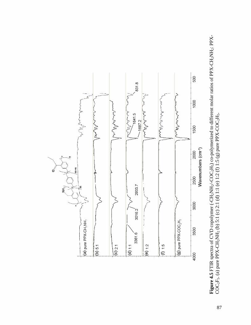
87
Fi
gure
4.5
FTI
R sp
ectra
of C
VD
cop
olym
er (-
CH
2NH
2/-C
OC
2H5)
co-
poly
mer
ized
to d
iffer
ent m
olar
ratio
s of P
PX-C
H2N
H2:
PPX
-C
OC
2F5.
(a) p
ure
PPX
-CH
2NH
2 (b)
5:1
(c) 2
:1 (d
) 1:1
(e) 1
:2 (f
) 1:5
(g) p
ure
PPX
-CO
C2H
5.
88
systematically (Figure 4.5). For example, bands at 3361.6 and 1641.5 cm-1 were distinct
until ratio of 1:2 was reached. Vibration at 1641.5 cm-1 is characteristic of NH2
scissoring stretches, while vibration at 3361.6 cm-1 indicates N-H stretches. As the
concentration of PPX-COC2H5 increased, these vibrations gradually disappeared. Other
subtle changes in FTIR spectra include a change in C-H bands with respect to their
relative intensities; with increasing content of PPX-CH2NH2 in the co-polymer, an
increase in the aliphatic C-H bands due to the COC2H5 group was observed. There
appears to be no evidence of cross-reaction between the amine and carbonyl functional
groups, as indicated by imine stretch (1655 cm-1) (Figures 4.4 and 4.5). In addition, for
each co-polymer spectrum, all FTIR bands can be accounted for based on the spectra of
the constituting mono-functional polymers (Figure 4.1).
Although FTIR spectra indicated agreement of the bulk co-polymer composition
with the loaded monomer ratio, this method has limited surface sensitivity and provides
averaged information of the entire polymer films. To assess the actual surface
composition of the co-polymer films, surfaces were analyzed by XPS, which can detect
the atomistic composition of a surface, usually within 5-10 nm. This technique can
provide a survey spectrum of all atoms present, as well as a high-resolution scan that
provide information about the binding state of a particular element. Table 4.1 summarizes
the chemical composition of all 1:1 ratios of the entire group of amino/carbonyl co-
polymers. Experimental data are compared to theoretical values obtained on the basis of
the starting materials assuming a 1:1 ratio of the two PCPs. Generally, all co-polymers
demonstrated good agreement between experimental values and theoretical compositions.
All high-resolution C1s spectra revealed π π* transitions, which are characteristic of

89
Table 4.1. Elemental compositions of CVD co-polymers containing 1:1 ratios of (a) (PPX-NH2):(PPX-R) (b) (PPX-CH2NH2):(PPX-R), as determined by XPS. Atomic composition results are shown on the top half of each table, while high resolution C1s spectra results are shown on the bottom. Theoretical calculations are based upon ideal deposition of the copolymer ratio.
X2
COC6H5 (1) COC2H5 (2) COC2F5 (3) COCF3 (4)
exper theor exper theor exper theor exper theor
NH2 series (A)
F --- --- --- --- 15.35 14.37 11.8 9.43 O 1.69 2.04 5.04 2.70 4.56 2.87 5.42 3.14 N 2.01 2.04 2.66 2.70 2.61 2.87 3.71 3.14 C (total) 96.3 95.92 92.29 94.59 77.48 79.89 79.06 84.28 C-C 84.01 87.76 76.26 83.78 60.53 68.39 66.02 74.85 C-N 2.33 2.04 2.33 2.70 2.54 2.88 2.17 3.14 C-C=O 3.8 4.08 4.58 5.41 --- --- --- --- C=O 1.91 2.04 4.37 2.70 3.39 2.88 4.25 3.14 π π* 4.25 --- 4.76 --- 4.04 --- 3.07 --- CF3 --- --- --- --- 3.49 2.88 3.56 3.14 CF2 --- --- --- --- 3.49 2.88 --- ---
CH2NH2 series (B)
F --- --- --- --- 17.18 13.97 8.54 9.15 O 1.9 2.00 2.63 4.49 4.84 2.79 5.35 3.05 N 1.23 2.00 2.63 2.36 1.90 2.79 2.84 3.05 C (total) 96.87 96.00 94.74 93.15 76.08 80.45 83.26 84.76 C-C 86.46 88.00 79.40 82.80 59.14 69.28 71.40 75.61 C-N 1.30 2.00 2.55 2.59 2.41 2.79 2.50 3.05 C-C=O 3.65 4.00 5.36 5.18 --- --- --- --- C=O 1.88 2.00 3.77 2.59 3.67 2.79 2.67 3.05 π π* 3.58 --- 3.66 --- 2.94 --- 3.43 --- CF3 --- --- --- --- 3.96 2.79 3.25 3.05 CF2 --- --- --- --- 3.96 2.79 --- ---
NH2
*
*
mm+n
n
X2
*
*
mm+n
n
X2
NH2

90
TCPS stainlesssteel
PPX-COCF3
copolymer PPX-CH2NH2
0
0.2
0.4
0.6
0.8
1
1.2
1.4
Fluo
resc
ence *
TCPS stainlesssteel
PPX-COCF3
copolymer PPX-CH2NH2
0
0.2
0.4
0.6
0.8
1
1.2
1.4
Fluo
resc
ence *
Figure 4.6 Fibrinogen adsorption on various substrates. Normalized fluorescence values are reported. Results were compared to TCPS. n=3, *: p<0.05.
aromatic polymers.[28] Nevertheless, discrepancies existed between experimental results
and theoretically calculated values. Even though a 1:1 monomer loading ratio is used,
fluctuations in ratios can occur during monomer sublimation.
4.3.3 Biocompatibility Studies
In order for such a polymer to function as an advanced biointerface, its
compatibility with cells must be assessed. We have demonstrated the ability of co-
polymer PPX-CH2NH2/-COCF3 to immobilize multiple ligands in defined ratios,[26] but
its short-term biocompatibility has not yet been tested. As shown in Figure 4.3, general
differences among the homopolymers existed with regard to HUVEC attachment and
morphology. To study the biocompatibility of co-polymers, we investigated several
cellular responses upon culture on CVD films. Initially, protein adsorption on these CVD
polymer coatings was evaluated using fibrinogen as a model protein. Fibrinogen was
chosen as a model protein due to its role in blood coagulation.[29] As many biologically
relevant devices contact blood upon implantation, fibrinogen adsorption behavior may be
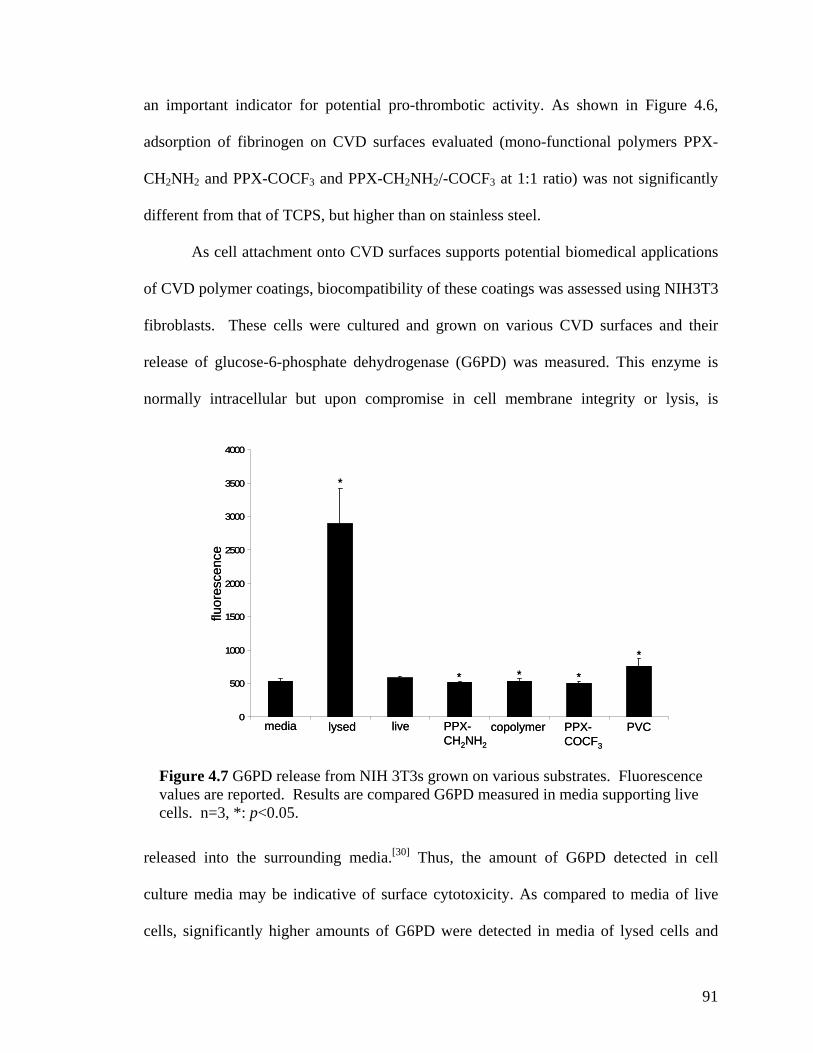
91
0
500
1000
1500
2000
2500
3000
3500
4000
fluor
esce
nce
* *
*
*
*
media lysed live PPX-CH2NH2
copolymer PPX-COCF3
PVC0
500
1000
1500
2000
2500
3000
3500
4000
fluor
esce
nce
* *
*
*
*
media lysed live PPX-CH2NH2
copolymer PPX-COCF3
PVC
Figure 4.7 G6PD release from NIH 3T3s grown on various substrates. Fluorescence values are reported. Results are compared G6PD measured in media supporting live cells. n=3, *: p<0.05.
an important indicator for potential pro-thrombotic activity. As shown in Figure 4.6,
adsorption of fibrinogen on CVD surfaces evaluated (mono-functional polymers PPX-
CH2NH2 and PPX-COCF3 and PPX-CH2NH2/-COCF3 at 1:1 ratio) was not significantly
different from that of TCPS, but higher than on stainless steel.
As cell attachment onto CVD surfaces supports potential biomedical applications
of CVD polymer coatings, biocompatibility of these coatings was assessed using NIH3T3
fibroblasts. These cells were cultured and grown on various CVD surfaces and their
release of glucose-6-phosphate dehydrogenase (G6PD) was measured. This enzyme is
normally intracellular but upon compromise in cell membrane integrity or lysis, is
released into the surrounding media.[30] Thus, the amount of G6PD detected in cell
culture media may be indicative of surface cytotoxicity. As compared to media of live
cells, significantly higher amounts of G6PD were detected in media of lysed cells and

92
(a) (b)
(c) (d) (e)
(a) (b)
(c) (d) (e)
Figure 4.8 Confocal microscopy images of NIH 3T3 murine fibroblasts grown on (a) poly(L-lysine) coated cover slip, (b) polyvinyl chloride film, (c) PPX-CH2NH2, (d) 1:1 ratio of PPX-CH2NH2 and PPX-COCF3, (e) PPX-COCF3 surfaces. Red: actin cytoskeleton (rhodamine-phalloidin), blue: nucleus (DAPI). n=3, representative images shown. All scale bars are 50 µm.
those grown on PVC (Figure 4.7). In contrast, lower G6PD release was observed from
cells grown on PPX-CH2NH2, the 1:1 co-polymer ratio, and PPX-COCF3 as compared to
live cells, suggesting that CVD surfaces may not cause cell death or lysis above that of
cells cultured on TCPS at the time point evaluated.
Morphologies of NIH3T3 fibroblasts grown on CVD homopolymers and
copolymer PPX-CH2NH2/-COCF3 were evaluated (Figure 4.8). As expected, murine
fibroblasts showed reduced growth on PVC disks, as many of the initially seeded cells
did not adhere or were detached during washing steps. Cells that remained adherent were
small in size and round in shape, suggesting lack of spreading and contact with the
surface. NIH3T3s grown on surfaces PPX-CH2NH2 and PPX-CH2NH2/-COCF3 showed
morphologies comparable to those grown on PLL cover slip, with cell spreading as
93
indicated by actin filaments. On PPX-COCF3, cells mostly aggregated, although more
cells remained adherent on this surface and more spreading was observed than on PVC.
In this set of experiments, introduction of polymer PPX-CH2NH2 to polymer PPX-
COCF3, as copolymer PPX-CH2NH2/-COCF3, improved NIH3T3 adhesion to the
polymer coating.
4.3.4 Reactivity Study
An ultimate goal of developing carbonyl-functionalized co-polymers is to
simultaneously immobilize multiple ligands. For the purpose of having orthogonal
reactivity under physiological conditions, it is necessary to understand the relative
chemical reactivity of the different carbonyl groups towards target molecules
(hydrazides). In this context, we analyzed the reaction kinetics of these different carbonyl
functionalities using in situ 1H NMR. Rather than reacting functionalized PCP
monomers, we chose to synthesize correspondingly functionalized p-xylenes, because the
constrained ring system of PCPs significantly alters the chemical reactivity of PCPs and
disqualify them as model reactants for PPXs. Functionalized p-xylenes may be
considered as the smallest repetition unit of the polymer coatings, and therefore more
closely resembles the PPX chain.
By integrating two specific peaks on the NMR spectra, one characteristic of the
reactants (-CH) and the other one indicating the product (-C=N-NH), the percent yield of
product was evaluated. Measurement frequency was decreased when the percent yield
reached a plateau. The percent yields were plotted as a function of time for the different
reactions with functionalized p-xylene derivatives. Figure 4.9 shows kinetic curves fitted

94
O
R
N
R
NH
HAc
O
(CH2)4CH3(a)
EtOD
Hexanoichydrazide
0
10
20
30
40
50
60
70
0 200 400 600 800 1000Time (min)
% Y
ield
R = CF3
R = C2F5
R = C2H 5R = C6H 5
(b)
O
R
N
R
NH
HAc
O
(CH2)4CH3(a)
EtOD
Hexanoichydrazide
O
R
N
R
NH
HAc
O
(CH2)4CH3(a)
EtOD
Hexanoichydrazide
0
10
20
30
40
50
60
70
0 200 400 600 800 1000Time (min)
% Y
ield
R = CF3
R = C2F5
R = C2H 5R = C6H 5
(b)
0
10
20
30
40
50
60
70
0 200 400 600 800 1000Time (min)
% Y
ield
R = CF3
R = C2F5
R = C2H 5R = C6H 5
(b)
Figure 4.9 (a) Protocol used to determine the reaction kinetics of different carbonyl-PPXs, using functionalized p-xylenes as test molecules. (b) Percent yield of carbonyl reactions with respect to time, based upon 1H NMR of characteristic reactant/product peaks.
to the experimental data. For most p-xylenes, NMR peaks characteristic of the product
were evident within 15-20 minutes of initiating the reaction. NMR spectra for benzoyl-
functionalized p-xylene showed no signals that were characteristic of the product over
reaction durations as long as 15 hrs. The fluorinated keto group was more reactive than
non-fluorinated groups. Of the functional groups, COCF3 was the most reactive,
followed by COC2F5, COC2H5, and COC6H5 in order of decreasing reactivity. Benzoyl
(COC6H5) group yielded essentially no product within the evaluated reaction times. On
the basis of these experiments, the trifluoroacetyl (COCF3) group was selected for further
multifunctional surface immobilization.
For surface immobilization, we used r-hirudin, a recombinant protein which
deactivates thrombin. Thrombin plays a central role in blood coagulation and mediates
restenosis.[31] Thus, the immobilization of hirudin may be one remediation approach for
blood-contacting devices, such as cardiovascular stents. In addition, heparin, a highly-
sulfated glycosaminoglycan anticoagulant, was utilized for immobilization. Hirudin and

95
heparin are expected to be immobilized onto copolymer coating of -CH2NH2/-COCF3
through aminomethyl group via a diisocyanate linker[32] and carbonyl groups via adipic
acid dihydrazide,[20] respectively.
For r-hirudin immobilization, the substrates were incubated with hexamethylene
diisocyanate, which is reactive towards amine groups.[18] FTIR spectroscopy confirmed
the presence of isocyanate (NCO) group on the amine and the copolymer surfaces with a
stretch at 2275 cm-1, which was absent in the FTIR spectra of the ketone surfaces. After
immobilization, r-hirudin was deprotected to restore biomolecular activity, and its
binding capacity was measured via a chromogenic substrate (S-2238) for thrombin.[18] In
this assay, surface-bound hirudin complexes thrombin, whereas free thrombin cleaves the
chromogenic substrate. As shown in Figure 4.10a , the absorbance was lower for amine-
containing homopolymer PPX-CH2NH2 and the co-polymer PPX-CH2NH2/-COCF3, as
compared to control surface of stainless steel, indicating a higher amount of surface-
bound hirudin on the surfaces of PPX-CH2NH2 or PPX-CH2NH2/-COCF3. Immobilized
heparin was photometrically quantified using toluidine blue test.[33] As the activity of
surface-bound heparin increases, more dye is surface-bound, leaving less dye in the
solution, yielding a lower UV-absorbance. Figure 4.10b shows that the absorbance/cm2
was lowest for PPX-COCF3 compared to the co-polymer PPX-CH2NH2/-COCF3 and the
stainless steel control, indicating a higher amount of heparin bound to PPX-COCF3.
While these results demonstrate successful reactivity of the co-polymer towards
both molecules, precise control of number of molecules immobilized to the surface poses
a challenge. Theoretically, the co-polymer contains half the number of active
immobilization sites compared to the homopolymer. However, this preliminary study

96
0.1
0.2
0.3
0.4
0.5
0.6
0.7
0.15
0.16
0.17
0.18
0.19
0.2(b)(a)
PPX-CH2NH2
copolymer SST PPX-COCF3
copolymer SST
Nor
mal
ized
abs
orba
nce
Nor
mal
ized
abs
orba
nce
**
*
*
0.1
0.2
0.3
0.4
0.5
0.6
0.7
0.15
0.16
0.17
0.18
0.19
0.2(b)(a)
PPX-CH2NH2
copolymer SST PPX-COCF3
copolymer SST
Nor
mal
ized
abs
orba
nce
Nor
mal
ized
abs
orba
nce
**
*
*
Figure 4.10 (a) Hirudin binding as measured by chromogenic assay. Normalized absorbance at 405 nm are reported. n=3, *: p<0.05 compared to stainless steel. (b) Heparin binding as measured by Toluidine Blue absorbance. Normalized absorbance at 631 nm are reported. n=3, *: p<0.05 compared to stainless steel.
suggests that not all groups are used for r-hirudin immobilization. This may be due to
steric hindrances, whereby immobilization of r-hirudin onto CH2NH2 groups results in
masking of other CH2NH2 sites available for immobilization. As such, appropriate
choice of spacers for the successful control of the ratio of immobilized agents will be
among the future challenges.
4.4 Conclusions
We have demonstrated versatility and activity of carbonyl-functionalized PPXs
polymerized from functionalized PCPs. Compositions of these polymers, both within the
bulk coating and at the surface, were verified by FTIR and XPS. The carbonyl-
functionalized polymers also exhibit drastic differences in crystallinity, which can be
attributed to compositional changes of the functional group. These subtle changes also
resulted in altered cellular morphologies on surfaces coated with CVD polymers.
97
In addition, we also copolymerized carbonyl-functionalized paracyclophanes with
amine-functionalized molecules. The resulting copolymers possessed mechanical
integrity and were dually-reactive through the presence of amine and carbonyl groups.
FTIR spectra illustrated control of copolymer compositions, which were relatively
homogeneous over several inches. These copolymers showed potential use as biomedical
coatings as determined by protein adsorption, cell adhesion, cytotoxicity assay, and
immobilization of antithrombotic drugs.

98
References
[1] A. Chilkoti, J.A. Hubbell, MRS Bulletin 2005, 30, 175.
[2] R. Langer, D.A. Tirrell, Nature 2004, 428, 487.
[3] M. Mrksich, MRS Bulletin 2005, 30, 180.
[4] [4a] P.S. Dittrich, K. Tachikawa, A. Manz, Anal. Chem. 2006, 78, 3887; [4b] D.R.
Reyes, D. Iossifidis, P.A. Auroux, A. Manz, Anal. Chem 2002, 74, 2623.
[5] H.J. Chung, T.G.Park, Adv. Drug Deliv. Rev. 2007, 59, 249.
[6] W.J. Kao, Biomaterials 1999, 20, 2213.
[7] M.B. Gorbet, M.V. Sefton, Biomaterials 2004, 25, 5681.
[8] B.D. Ratner, A.S. Hoffman, F.J. Schoen, J.E. Lemons, “Biomaterials Science”, 2nd
edition, Elsevier Inc., 2004, p. 332-338.
[9] [9a] M. Yoshida, R. Langer, A. Lendlein, J. Lahann, Poly. Rev. 2006, 46, 347. [9b]
D.J. Mooney, E.A. Silva, Nat. Mater. 2007, 6, 327.
[10] F.F. Shi, Surf. and Coatings Tech. 1996, 82, 1.
[11] [11a] R.G. Nuzzo, D.L. Allara., J. Am. Chem. Soc. 1983, 105, 4481; [11b] S. Onclin,
B.J. Ravoo, D.N. Reinhoudt. Angew. Chem. Inter. Ed. 2005, 44, 6282.
[12] M. Chen, H. Liang, Y. Chiu, Y. Chang, H. Wei and H. Sung, J. Contr. Release 2005,
108, 178.
[13] B.D. Ratner, A.S. Hoffman, F.J. Schoen, J.E. Lemons, “Biomaterials Science”, 2nd
edition, Elsevier Inc., 2004, p. 1-3.
[14] G. Mani, M.D. Feldman, D. Patel, C.M. Agrawal, Biomaterials 2007, 28, 1689.
[15] J. Lahann, H. Hocker, R. Langer, Angew. Chem. Int. Ed. 2001, 40, 726.

99
[16] J. Lahann, R. Langer, Macromolecules 2002, 35, 4380; H. Nandivada, H.Y. Chen, L.
Bondarenko, J. Lahann, Angew. Chem. Int. Ed. 2006, 45, 3360; X. Jiang, H.Y. Chen, G.
Galvan, M. Yoshida, J. Lahann, Adv. Func. Mater. 2008, 18, 27; J. Lahann, M. Balcells,
T. Rodon, J. Lee, I.S. Choi, K.F. Jensen, R. Langer, Langmuir 2002, 18, 3632; J. Lahann,
R. Langer, Macromol. Rapid Commun. 2001, 22, 968.
[17] J. Lahann, Polym. Int. 2006, 55, 1361.
[18] J. Lahann, W. Plüster, T. Rodon, M. Fabry, D. Klee, H.-G. Gattner, H. Höcker,
Macromol. Biosci. 2002, 2, 82.
[19] P. Simon, S. Mang, A. Hasenhindl, W. Gronski, A. Greiner, Macromolecules 1998,
31, 8775; C. Schmidt, V. Stuempflen, J. Wendorff, A. Hasenhindl, W Gronski, M.
Ishaque, A. Greiner, Acta Polym 1998, 49, 232; L. You, G. Yang, C. Lang, P. Wu, J.
Moore, J. McDonald, et. al., J. Vac. Sci. Tech. A 1993, 11, 3047.
[20] H. Nandivada, H.Y. Chen, J. Lahann, Macromol. Rapid Commun. 2005, 26, 1794.
[21] H. Y. Chen, J. M. Rouillard, E. Gulari, J. Lahann. Proc Natl Acad Sci U S A. 2007.
104, 11173.
[22] H.Y. Chen, J. Lahann, Adv. Mater. 2007, 19, 3801; S. Thévenet, H.-Y. Chen, J.
Lahann, F. Stellacci, Adv. Mater. 2007, 19, 4333.
[23] K.Y. Suh, R. Langer, J. Lahann, Adv. Mater. 2004, 16, 1401; H.Y. Chen, J. Lahann,
Anal. Chem. 2005, 77, 6909.
[24] J. Lahann, D. Klee, H. Hocker, Macromol. Rapid Commun. 1998, 19, 441.
[25] M. Morgen, S.H. Rhee, J.H. Zhao, I. Malik, T. Ryan, H.M. Ho, M.A. Plano, P. Ho,
Macromolecules 1999, 32, 7555; J.J. Senkevich, S.B. Desu, V. Simkovic, Polymer 2000,
41, 2379; S.Y. Park, S.N. Chvalun, A.A. Nikolaev, K.A. Mailyan, A.V. Pebalk, I.E.

100
Kardash, Polymer 2000, 41, 2937; D. Klee, N. Weiss, J. Lahann. Vapor-Based
Polymerization of Functionalized [2.2]Paracyclophanes: A Unique Approach towards
Surface-Engineered Microenvironments“ Chapter 18, Modern Cyclophane Chemistry,
Wiley-VCH, Weinheim 2004, p463.
[26] Y. Elkasabi, H.Y. Chen, J. Lahann, Adv. Mater. 2006, 18, 1521.
[27]; D.R. Critchley Biochem Soc Trans 2004, 32, 831; E. Zamir, B. Geiger. J Cell Sci
2001, 114, 3583.
[28] J.A. Gardella, S.A. Ferguson, R.L. Chin, Appl. Spectrosc. 1986, 40, 224.
[29] S. Beguin, R. Kumar, Thromb. Haemost. 1997, 78, 590.
[30] Z. Zhang, K. Apse, J. Pang, R.C. Stanton, J. Biol. Chem. 2000, 275, 40042.
[31] J.F. Schmedtje Jr., M.S. Runge, D. Baykal, Am. J. Cardiol. 1995, 75, 82B.
[32] J. Lahann, D. Klee, W. Pluester, & H. Hoecker, Biomaterials 2001, 22, 817.
[33] H. Chen, Y. Chen, H. Sheardown, M.A. Brook, Biomaterials 2005, 26, 7418.
101
CHAPTER 5
POLYMER COATINGS WITH REACTIVE SURFACE COMPOSITION GRADIENTS
The materials in this chapter have been adapted with minor modifications from
the following published article: Y. Elkasabi, J. Lahann, Macromolecular Rapid
Communications 2009, 30, 57-63.
5.1 Background and Motivations
In nature, biological information is typically encoded and displayed in the form of
continuous gradients mitigating important cellular events, such as cell signaling, cell
development, or chemotaxis. Mimicking surfaces with natural, spatially continuous
gradients is therefore of decisive importance to a range of biological applications
including studies of neuronal growth and differentiation,[1-3] the design of cell migration[4-
6] and inflammation[7] assays, microfluidic cell culture,[8] or discovery-driven
(bio)materials research.[9,10] In spite of the importance of surface gradients for biological
applications, their realization, especially with biomedically relevant polymers, has been
challenging. Methods of making gradients are often relatively undifferentiated and are
potentially associated with a number of limitations: (i) Translation of chemical gradients
into biological gradients requires immobilization of biomolecules, which is often not
possible with existing gradient materials.[11,12] (ii) Due to technical constraints, such as
chemical resolution, resulting gradients are often intrinsically discontinuous with
102
potentially steep transitional steps.[13-15] (iii) Methods for making gradients are in many
cases restricted to a particular surface chemistry, such as thiols to gold or siloxanes to
glass or silicon. (iv) As a consequence, the range of materials, to which a given protocol
can be applied, may become rather limited.[16,17] Although a range of methods have been
developed that have the potential to address some or all of these challenges, experimental
deficiencies are still in gross discrepancy to the rather elaborated approaches that have
been developed over the last two decades for inorganic surface gradients. There, the use
of vapor-based fabrication methods for inorganic materials resulted in efficient, high-
throughput screening for catalytic activity, conductivity, or luminescence.[18] Where
fabrication of gradients in inorganic materials has greatly benefited from anisotropic
chemical vapor deposition,[18] polymer gradients have been so far prepared by solution-
based processes, such as bulk diffusion,[11,19] microfluidic pathways,[13,14]
lithography,[15,16,20] or combinations thereof.[12,17]
By taking advantage of vapor-based polymers, we have now established a simple
method for polymer gradients with continuously changing surface compositions. Given
the wide-range applicability of CVD polymerization to a diverse set of different
substrates,[21] polymer gradients based on CVD polymer technology have the potential to
expedite biomaterials discovery, much like it has been witnessed for inorganic materials
over the last decades.[22]
Our approach towards polymer gradients takes advantage of chemical vapor
deposition (CVD) polymerization of substituted [2.2]paracyclophanes to prepare polymer
coatings with identical backbone chemistries, but different functional side groups.[21]
Compared to plasma polymerization, which has been previously used to prepare polymer

103
gradients,[23] CVD polymerization of functionalized poly-p-xylylene has the potential to
create robust, chemically well-defined polymers with a diverse range of reactive side
groups – typically without appreciable side reactions. Recently, co-polymerization of two
different [2.2]paracyclophanes resulted in surfaces with fine-tunable composition
ratios.[24] With the concept of CVD co-polymerization demonstrated, the fundamental
feasibility of a vapor-based gradient fabrication tool that mimics the processes developed
for inorganic materials discovery is now within reach for soft materials.
5.2 Experimental Methods
CVD Copolymerization – CVD depositions were carried out in a custom-built chemical
vapor deposition system, equipped with two inlet sources. Each source consisted of a
quartz tube encased in a 3-zone tube furnace, and both tubes entered the deposition
chamber directly opposite to each other. 4-trifluoroacetyl[2,2]paracyclophane monomer
(1) was synthesized using an established synthesis route.[25] 4-
Aminomethyl[2,2]paracyclophane monomer (2) was purchased from Uniglobe Kisco,
Inc. (White Plains, NY) and used as-received. Monomer 1 and monomer 2 were loaded
separately into two feed dishes, with each dish loaded into its own source. A system
pressure of 0.165 Torr and sublimation temperatures between 80-110 oC were used to
ensure sublimation. Argon carrier gas was used to independently control the flow
velocities of sublimated monomer (1) and monomer (2). Three different process
conditions produced gradients with differing compositional rates of change. Condition 1:
M1 = 160 mg, M2 = 205 mg, Ar1= 6.5 sccm, Ar2 = 32 sccm. Condition 2: M1 = 200 mg,
M2 = 205 mg, Ar1 = 7.2 sccm, Ar2 = 29.7 sccm. Condition 3: M1 = 120 mg, M2 = 205 mg,

104
Ar1 = 5.7 sccm, Ar2 = 35 sccm. The sample holder was set 4 inches below the position of
both sources. To ensure gradient formation, the sample holder was not rotated. Although
the sample holder remained at 15 oC, a copper plate was set on top of the sample holder,
in order to control the sample’s angle of inclination. Deposition occurred on silicon, gold,
and glass substrates. To minimize wall deposition, the chamber wall was heated to 120
oC.
Surface Characterization – X-ray photoelectron spectroscopy (XPS) was performed on
CVD-coated silicon substrates (1cm x 1cm). XPS data were recorded on an Axis Ultra X-
ray photoelectron spectrometer (Kratos Analyticals, UK) equipped with a
monochromatized AlKα X-ray source. All spectra were calibrated with respect to the
non-functionalized aliphatic carbon with a binding energy of 285.0 eV and were
corrected for atomic sensitivity factors. Thicknesses were recorded at a wavelength of
532 nm using an EP3-SW imaging ellipsometry (Nanofilm Technologie GmbH,
Germany). Four-zone nulling experiments were performed at an angle of incidence of
70o, and an anisotropic Cauchy model was used to model the ellipsometric parameters psi
and delta. Infrared spectroscopy was performed on a Nicolet 6700 spectrometer utilizing
the grazing angle accessory (Smart SAGA) at a grazing angle of 85o. FTIR spectra were
corrected for any residual baseline drift. Au-coated Si substrates were used for FTIR
measurements, using blank Au-coated Si as a reference.
Surface Modification – Surface reactions were performed on CVD-coated glass
microscope slides (3’’ x 1’’, Fisher Inc.). Biotin hydrazide and rhodamine-linked
streptavidin were purchased from Pierce Inc., and Atto 655 NHS ester was purchased
from Sigma Aldrich. All surface reaction experiments were performed on glass

105
substrates. A PDMS membrane was molded and cut in the shape of a long rectangle made
for holding fluid within its boundaries. The membrane was placed on the film and
allowed to seal, and the reaction buffer filled the membrane. Then the entire slide was
immersed in washing buffer, with the PDMS still remaining on the surface. Reactions
were carried out in a closed Petri dish, to prevent the reaction mixtures from drying out.
All surfaces were rinsed with DI water after applying the ligands and using the washing
buffers. Consecutive surface reactions were conducted at each location. Fluorescence
images and intensities were acquired using a GenePix 4000B scanner with 532 nm (17
mW) and 635 nm (10 mW) lasers. Both excitation wavelengths were scanned
simultaneously at 100 µm spatial resolution. Colors shown in the scanning images were
not true colors, but were set for best visualization.
Ligand 1: 0.5 ml of anhydrous dimethylformamide was added to 1 mg Atto 655 NHS
ester. From this, 5.0 µl were diluted with 7 ml 0.1 M sodium bicarbonate buffer (pH 8.3),
containing 0.02% (v/v) Tween 20. NHS esters are time-sensitive in aqueous solution, so
the buffer was applied to the film immediately upon dilution. The solution was incubated
for 1 hour at room temperature, after which the surface was rinsed with ethanol for 10
minutes and with PBS/Tween solution for 30 minutes.
Ligand 2: Biotin hydrazide was diluted to 10 mM in phosphate buffered saline (PBS pH
7.4). The solution was acid-catalyzed (HAc) prior to surface application. Incubation time
lasted 7 to 10 minutes, which was followed by a wash of PBS containing 0.02% (v/v)
Tween 20. The area was then applied with rhodamine-linked streptavidin solution (0.075
mg/ml in PBS; 0.02% (v/v) Tween 20; 0.1% (w/v) bovine serum albumin) for 15

106
minutes. Finally, the entire glass slide was immersed for 1 hour in a PBS/Tween/BSA
solution.
5.3 Results and Discussion
5.3.1 Polymer Gradient Deposition
The experimental setup for gradient co-polymerization of functionalized
[2,2]paracyclophanes is illustrated in Figure 5.1. Instead of the traditional single-source
CVD system,[26] a polymerization chamber with two sources at an 180o angle has been
designed. Each source can independently provide different types of starting materials.
During CVD copolymerization using dual sources, each ring-constrained
[2.2]paracyclophane is thermally converted into corresponding quinodimethanes and
transferred into the reaction chamber. Next, the quinodimethanes spontaneously
copolymerize below a certain threshold temperature onto a temperature-controlled
substrate (typically 40 to 60 ºC depending on the chemical structure of the
[2.2]paracyclophane). While the monomer flows over a substrate with a temperature
below this threshold temperature, gradual depletion of the monomer from the gas phase
occurs, resulting in a gradual decrease in polymer composition of the vapor phase. If two
monomers are deposited in a countercurrent manner to each other, each monomer’s
concentration should decrease with increasing distance from the respective source. As a
consequence, the relative ratio of the components, which make up the polymer film, will
form a continuous gradient. In order for gradient deposition to occur in this manner,
however, the mass transport properties of both monomers must allow for sufficient
manipulation.

107
Fi
gure
5.1
. A si
de-v
iew
sche
mat
ic o
f the
cus
tom
-bui
lt tw
o-so
urce
CV
D sy
stem
. Eac
h so
urce
con
sist
s of a
qua
rtz tu
be th
at p
asse
s th
roug
h a
3-zo
ne fu
rnac
e an
d th
en c
onne
cts i
nto
the
depo
sitio
n ch
ambe
r. B
oth
the
tube
s and
the
cham
ber t
oget
her a
re h
eld
at 0
.16
Torr
. (1)
and
(2) s
ublim
ate,
und
ergo
pyr
olys
is, a
nd th
en c
opol
ymer
ize
to d
epos
it on
the
sam
ple
hold
er. T
he sp
ecifi
ed p
roce
ss
cond
ition
s cre
ate
a po
ly(p
-xyl
ylen
e) (P
PX) f
ilm p
osse
ssin
g a
func
tiona
l com
posi
tion
grad
ient
.
108
Some process variables that can affect the gradient formation include system
pressure, argon flow rates, substrate temperature, sample height, monomer loading, and
pyrolysis temperatures. The CVD-based gradient experiments were conducted in a
vacuum chamber, which accommodates a 30.5 cm diameter sample holder placed
between the two source inlets. Starting material 4-trifluoroacetyl-[2.2]paracyclophane (1)
was loaded into source 1, while 4-aminomethyl-[2.2]paracyclophane (2) was loaded into
source 2. Pyrolysis temperatures of 670 oC were used in both source systems. Under these
conditions, paracyclophanes 1 and 2 were converted into the corresponding
quinodimethanes 3 and 4. Deposition rates were adjusted by controlling the sublimation
rates of starting material 1 and 2, so that sublimation of both dimers started and finished
simultaneously after a 10-minute period. Dimer sublimation rates were controlled by
changing the amount of loaded starting material, while keeping sublimation temperatures
and pressure constant. In addition, rapid venting of the deposition chamber with argon
after CVD deposition improved gradient quality. Gradient co-polymerization yielded
continuous polymer films with thicknesses varying between 120-190 nm. Thickness
differences were occasionally observed along the polymer gradient, but did not
compromise the chemical composition gradients or the gradient reactivity.
Steady gradient formation with respect to bulk composition across the polymer
films was evaluated using a combination of surface analytical methods. Fourier transform
infrared (FTIR) spectroscopy was chosen because of its ability to detect relative changes
in characteristic bond vibrations. The trifluoroacetyl functional group of homopolymer 6
resulted in characteristic vibrational modes at 1716 cm-1 associated with the carbonyl
group and at 1200, 1152, 973 cm-1 (C-F stretches). Aminomethyl groups have

109
characteristic N-H and C-N signals at 3368, 3302, 1640, and 829 cm-1, respectively.
During CVD co-polymerization, gold substrates were placed at specific positions along
the length of the sample holder, and the polymer coating was deposited using the two-
source system (Figure 5.1). Relative ratios of vibrational signal intensities associated with
trifluoroacetyl and aminomethyl groups were determined for each substrate. Samples
were placed at various locations on a 12’’ diameter sample holder. Figure 5.2 shows IR
spectra at various locations along the sample holder. A detailed FTIR analysis of these
BA CSource A Source B
(a)
A
% R
efle
ctan
ce
500 1000 1500 2000 2500 3000 3500 4000 Wavenumbers (cm-1)
B
C3368, 3302N-H 2929
C-H
1716C=O
1640N-H
1200, 1152C-F
973 829
(b)1716C=O
1227, 1200, 1152C-F
BA CSource A Source B
(a)
A
% R
efle
ctan
ce
500 1000 1500 2000 2500 3000 3500 4000 Wavenumbers (cm-1)
B
C3368, 3302N-H 2929
C-H
1716C=O
1640N-H
1200, 1152C-F
973 829
(b)1716C=O
1227, 1200, 1152C-F
Figure 5.2. (a) Side view of the CVD sample holder. AB = BC = 7.6 cm. AC = 15.2 cm. (b) FTIR spectra of CVD copolymers produced from the conditions of scheme 1. The bulk ratio of CVD copolymer changes with respect to position along the sample holder.
1 2

110
1000
15
00
2000
25
00
3000
35
00
4000
W
aven
umbe
rs(c
m-1
)
0.75
’’
1.5’
’
2.25
’’
3.0’
’
3.75
’’
4.5’
’
1716
C=O
1227
, 120
0, 1
152
C-F
973
829
3368
, 330
2N
-H29
29C
-H16
40N
-H10
00
1500
20
00
2500
30
00
3500
40
00
Wav
enum
bers
(cm
-1)
0.75
’’
1.5’
’
2.25
’’
3.0’
’
3.75
’’
4.5’
’
1716
C=O
1227
, 120
0, 1
152
C-F
973
829
3368
, 330
2N
-H29
29C
-H16
40N
-H
F
igur
e 5.
3. F
TIR
spec
tra o
f CV
D c
opol
ymer
gra
dien
ts, u
sing
con
ditio
n 2

111
samples revealed a transition from strong trifluoroacetyl signals to strong aminomethyl
signals, most evidently from the band vibrations at 973 and 829 cm-1. Correlation
between FTIR and XPS data provides access to polymer compositions at the surface.[24]
Upon calibration using the FTIR technique, sample point A was related to a molar ratio
of 1:2 (PPX-CH2-NH2 : PPX-COCF3), sample point B corresponded to the equimolar
ratio of the two building blocks, and sample point C was related to a 5:1 excess of PPX-
CH2-NH2, at fixed flow rates of 6.5 sccm source A and 32.0 sccm source B. FTIR spectra
from other CVD deposition conditions revealed analogous results, indicating different
rates of change across the substrate (Figure 5.3). Differences in the chemical side groups
of the starting materials had a profound impact on the spreading of the resulting polymer
films. This agrees well with a recent study on penetration of CVD coatings into confined
microchannels.[27]
The FTIR study was complemented by a detailed X-ray photoelectron
spectroscopy (XPS). In general, XPS provides information about the polymer
composition within the top 5-10 nm of a polymer film.[28] We used XPS in its survey
spectrum mode to study the composition of three different CVD films made by gradient
copolymerization on a silicon substrate. Fluorine and nitrogen were selected as reporter
atoms for monomers 3 and 4, respectively. On the basis of these reporter atoms, relative
surface ratios were calculated for each film. Figure 5.4 shows the copolymer
concentration profiles based on the XPS results. Upon inspection of the surface
composition from Figure 5.2, gradually changing concentrations can be observed ranging
from 26% of compound 4 at positions A (closest to source 1) to 44% at position B, to
85% at position C (closest to source 2). A detailed analysis on the basis of 14 data points

112
0 2 4 6 8 10 12 14 1610
20
30
40
50
60
70
80
90
Condition 1 Condition 2 Condition 3
R2=0.95
% P
PX
-CH
2NH
2 in
copo
lym
er
length (cm)
R2=0.95
R2=0.94
Figure 5.4. Copolymer compositions along the surface gradient, based upon XPS survey spectra. Copolymer ratios are calculated based upon the percentage of fluorine and nitrogen, both characteristic of (1) and (2), respectively. The concentration of aminomethyl groups increases with respect to position along the substrate. The compositional rate of change can be controlled by manipulating argon flow rates and sublimation rates.
along the trajectory between the two source inlets revealed a linear change in surface
composition over a distance of 15.2 cm. Simple modulation of the process parameters
allowed for controlled manipulation of the gradient compositional slope. To vary the
compositional slope of the gradients, cooperative control of argon flow rates and
monomer sublimation rates resulted in substantially different gradient slopes as shown in
Figure 5.4. As the ratio of argon flow rates increases (Ar1/Ar2), an increase in
compositional slope of the gradients was observed. Fundamentally, effective gradient
formation required the deposition zones of both PCP’s to sufficiently overlap on the
substrate, which was placed onto a cooled sample holder to enhance deposition pressure.

113
If the deposition zones were identical for both PCP’s, the sample had to be placed in the
center between both sources to obtain optimum deposition. However, it has already been
shown for CVD polymerization within microchannels,[27] that trifluoroacetyl-
functionalized PCP possesses a higher mobility as compared to the amine-functionalized
dimers, which effectively moves the deposition zone away from the source of the
trifluoroacetyl-functionalized PCP and closer to the source of the amino-functionalized
PCP. When samples were placed outside of the region of overlapping deposition zones,
the resulting gradients were flat and very difficult to control. Moreover, modulation of
parameters associated with the CVD polymerization of trifluoroacetyl-functionalized
PCP can be expected to be more effective when controlling gradient properties, such as
compositional profiles and slopes. Increasing the mass and argon flow of paracyclophane
1, while decreasing the argon flow of paracyclophane 2, increased the compositional
slope of the gradient, as long as the mass of compound 2 was held constant. Because of
the different monomer mobility, changes made to flow rates of the amine were small
enough, to ensure that the aminomethyl-rich end of the gradient remains unaffected by
the increase in trifluoroacetyl-functionalized monomers. Assuming that the sublimation
temperatures remain constant, the aforementioned trends in deposition conditions can be
used to produce compositional gradients with predictable slopes.
To verify this, three plots are shown in Figure 5.4, which represent three CVD
conditions outlined in the experimental section. Linear trends can be fitted to each plot,
each with an R2 value of at least 0.94. In spite of the steeper compositional gradient, the
actual range of realizable compositions remains approximately unaltered. The ability to
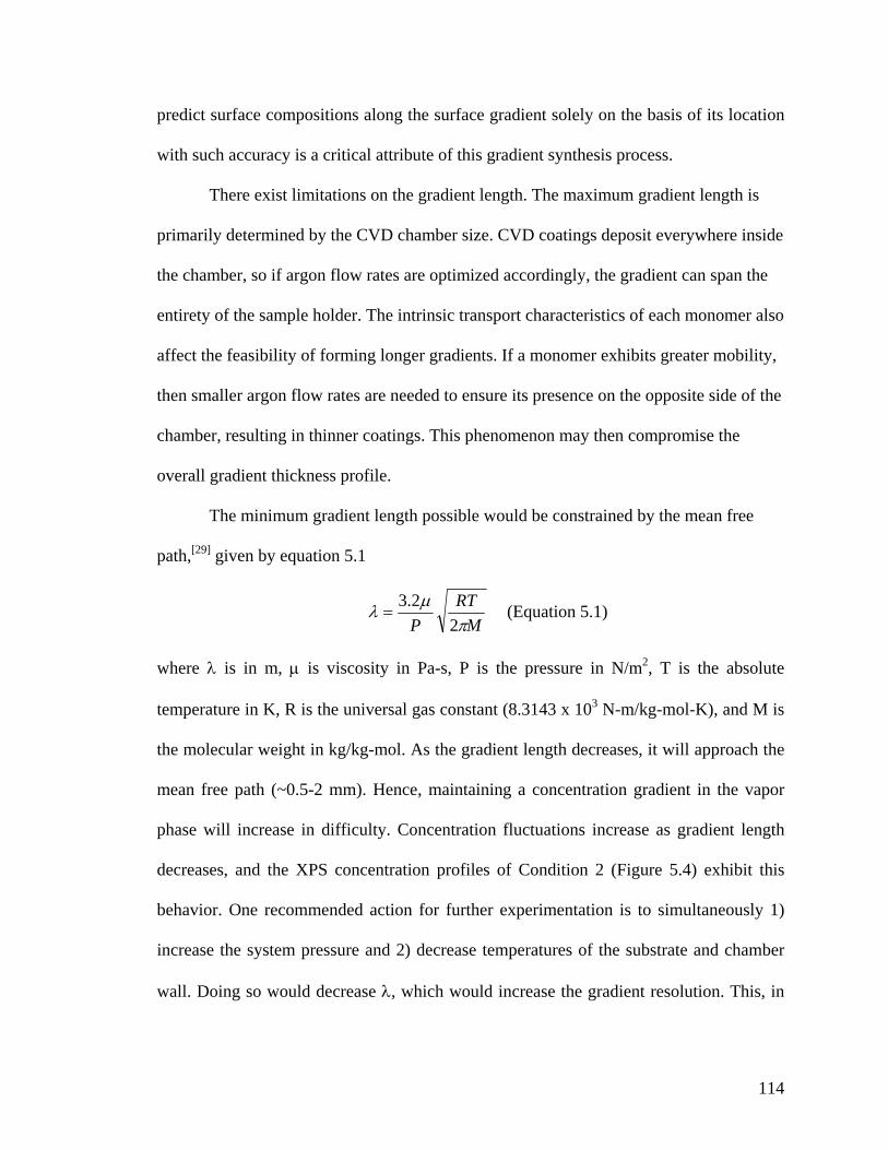
114
predict surface compositions along the surface gradient solely on the basis of its location
with such accuracy is a critical attribute of this gradient synthesis process.
There exist limitations on the gradient length. The maximum gradient length is
primarily determined by the CVD chamber size. CVD coatings deposit everywhere inside
the chamber, so if argon flow rates are optimized accordingly, the gradient can span the
entirety of the sample holder. The intrinsic transport characteristics of each monomer also
affect the feasibility of forming longer gradients. If a monomer exhibits greater mobility,
then smaller argon flow rates are needed to ensure its presence on the opposite side of the
chamber, resulting in thinner coatings. This phenomenon may then compromise the
overall gradient thickness profile.
The minimum gradient length possible would be constrained by the mean free
path,[29] given by equation 5.1
M
RTP πµλ
22.3
= (Equation 5.1)
where λ is in m, µ is viscosity in Pa-s, P is the pressure in N/m2, T is the absolute
temperature in K, R is the universal gas constant (8.3143 x 10³ N-m/kg-mol-K), and M is
the molecular weight in kg/kg-mol. As the gradient length decreases, it will approach the
mean free path (~0.5-2 mm). Hence, maintaining a concentration gradient in the vapor
phase will increase in difficulty. Concentration fluctuations increase as gradient length
decreases, and the XPS concentration profiles of Condition 2 (Figure 5.4) exhibit this
behavior. One recommended action for further experimentation is to simultaneously 1)
increase the system pressure and 2) decrease temperatures of the substrate and chamber
wall. Doing so would decrease λ, which would increase the gradient resolution. This, in

115
(a) (b)CF3O CF3O
Bifunctional co-polymer
NH2
CH2
NH2
CH2
O
HN
CH2
O
HN
CH2
CF3N
O
NH
CF3N
O
NH
Bifunctional co-polymer
Controlledimmobilization
(c)
0 2 4 6
2
4
6
Position (cm)
Gre
en fl
uore
scen
ce
20
30
40
50
R2 = 0.98
Red fluorescence
R2 = 0.88
(a) (b)CF3O CF3O
Bifunctional co-polymer
NH2
CH2
NH2
CH2
O
HN
CH2
O
HN
CH2
CF3N
O
NH
CF3N
O
NH
Bifunctional co-polymer
Controlledimmobilization
CF3O CF3O
Bifunctional co-polymer
NH2
CH2
NH2
CH2
CF3O CF3O
Bifunctional co-polymer
NH2
CH2
NH2
CH2
O
HN
CH2
O
HN
CH2
CF3N
O
NH
CF3N
O
NH
Bifunctional co-polymer
O
HN
CH2
O
HN
CH2
CF3N
O
NH
CF3N
O
NH
Bifunctional co-polymer
Controlledimmobilization
(c)
0 2 4 6
2
4
6
Position (cm)
Gre
en fl
uore
scen
ce
20
30
40
50
R2 = 0.98
Red fluorescence
R2 = 0.88
Figure 5.5. (a) Schematic of the biomolecular immobilization process (b) Fluorescence image and (c) intensity profiles of immobilized fluorescent dyes across a CVD polymer gradient. Both Atto 655 NHS ester (red) and biotin hydrazide with rhodamine-tagged streptavidin (green) reacted over the same regions, showing that the composition gradient can be converted into immobilization gradients.
combination with the aforementioned trends in deposition parameters, could allow for the
deposition of gradients shorter than 8 cm.
5.3.2 Surface Reactions
To confirm that free amino and trifluoroacetyl groups are available at the surface
in the expected ratios, we reacted the polymer gradients with two fluorescence-based
reporter reactants with orthogonal reactivity. Model surface reactions were employed,
which followed previously established reactions.[24] First, Atto 655 NHS ester was
reacted with the primary amines of monomer 4, followed by reaction of the
trifluoroacetyl groups of monomer 3, with biotin hydrazide to form the corresponding
hydrazones. Rhodamine-linked streptavidin was then used to visualize biotin

116
attachment.[30] Figure 5.5 shows a fluorescence scanning image and normalized
fluorescence profiles for a surface gradient, which was reacted with two fluorescent dyes.
To obtain fluorescence profiles, actual fluorescence values within areas of ligand
immobilization were divided by the polymer background fluorescence. As the
concentration changes across the substrate, the ratio of red versus green fluorescence
intensities is altered correspondingly. The fluorescence gradient changed linearly and
correlated well with the surface composition ratios obtained by XPS. This is important,
because XPS provides information that averages over the outermost 5 to 10 nm, while the
fluorescence titration only reflects chemical groups incidentally available at the surface.
Thus, the gradient surfaces not only have well predictable surface composition gradients,
but these gradients also correspond to a gradual change in surface reactivity.
5.4 Conclusions
In summary, we have developed a straightforward process for the fabrication of
continuous, reactive composition gradients based on vapor-deposited polymer thin films.
These poly(p-xylylene) coatings consist of a uniform polymeric backbone, with gradually
changing functional side groups present at the surface. The films possess a gradient of
two reactive functional groups, allowing for independent manipulation of physical and/or
chemical properties. By controlling CVD polymerization parameters, such as argon flow
rates and sublimation rates, the slope of the compositional gradients can be adjusted,
while maintaining a linear trend. Most importantly, we were able to selectively
immobilize fluorescently-labeled ligands onto the reactive polymer gradients. Not only is
CVD polymerization conformal over complex geometries, but the deposition can occur
117
over various substrate materials. In addition, the CVD co-polymerization approach used
for preparing the polymer gradients is not limited to the two functionalities discussed
herein. A range of different functionalities including alcohols,[31] amines,[32] ketones,[33]
esters,[34] alkynes,[35] and aldehydes[36] can be incorporated into these coatings and
selecting dimeric precursor(s) with the appropriate functional group may create gradients
of a wide range of different functionalities. CVD composition gradients have the
potential to address many common setbacks and limitations of currently employed
methods for polymer gradients and may find applications in a range of biotechnological
devices. Specific applications of PPX gradients will vary depending on the gradient
characteristics, including the gradient length. Longer gradients (7 – 12’’) would be useful
for generating combinatorial libraries for high-throughput experimentation. A large
number of relatively small substrates can be loaded onto the sample holder, within the
region of gradient deposition. The local composition within each substrate would be a
homogeneous copolymer. Moderately short gradients (2 – 7’’) of biochemical signals
have greater application in tissue regeneration and scaffold constructs.[37] Relevant
signals include growth factors and peptide sequences. Shorter gradients (< 2’’), if
successfully fabricated with CVD, have potential use in microfluidic bioassays and
regulation of cellular migration and differentiation of most cell lines.
118
References
[1] H.J. Song, M. Poo, Curr. Opin. Neurobio., 1999, 9, 355-363.
[2] S.K.W. Dertinger, X. Jiang, Z. Li, V.N. Murthy, G.M. Whitesides, Proc. Natl. Acad.
Sci., 2002, 99(20), 12542-12547.
[3] A.C. von Philipsborn, S. Lang, J. Loschinger, A. Bernard, C. David, D. Lehnert, F.
Bonhoeffer, M. Bastmeyer, Development, 2006, 133, 2487-2495.
[4] C. A. Parent, P.N. Devreotes, Science 1999, 284, 765-770.
[5] R.T. Tranquillo, D.A. Lauffenburger, S.H. Zigmond, J. Cell Biol. 1988, 106, 303-309.
[6] H. Mao, P.S. Cremer, M.D. Manson, Proc. Natl. Acad. Sci. U.S.A. 2003, 100, 5449.
[7] R.J. Mrsny, A.T. Gewirtz, D. Siccardi, T. Savidge, B.P. Hurley, J.L. Madara, B.A.
McCormick, Proc. Natl. Acad. Sci., 2004, 101, 7421.
[8] L. Ionov, N. Houbenov, A. Sidorenko, M. Stamm, S. Minko, Adv. Func. Mater. 2006,
16, 1153-1160.
[9] [9a] J.C. Meredith, J.L. Sormana, B.G. Keselowsky, A.J. Garcia, A. Tona, A. Karim,
E.J. Amis, J. Biomed. Mater. Res. 2003, 66A, 483-490; [9b] P. Zapata, J. Su, A.J. Garcia,
J. C. Meredith, Biomacromol. 2007, 8, 1907.
[10] [10a] J. Genzer, R.R. Bhat, Langmuir 2008, 24, 2294; [10b] T. Winkler, N. Ballav,
H. Thomas, M. Zharnikov, A. Terfort, Angew. Chem. Int. Ed. 2008, 47, 7238.
[11] M.K. Chaudhury, G.M. Whitesides, Science 1992, 256(5063), 1539.
[12] T.M. Keenan, C.H. Hsu, A. Folch, Appl. Phys. Lett. 2006, 89, 114103.
[13] N.L. Jeon, S.K.W. Dertinger, D.T. Chiu, I.S. Choi, A.D. Stroock, G.M. Whitesides,
Langmuir 2000, 16, 8311.
[14] J.A. Burdick, A. Khademhosseini, R. Langer, Langmuir 2004, 20(13) 5153.

119
[15] N.D. Gallant, K.A. Lavery, E.J. Amis, M.L. Becker, Adv. Mater. 2007, 19, 965.
[16] N. Ballav, A. Shaporenko, A. Terfort, M. Zharnikov, Adv. Mater, 2007, 19, 998-
1000.
[17] [17a] C. Xu, S.E. Barnes, T. Wu, D.A. Fischer, D.M. DeLongchamp, J.D. Batteas,
K.L. Beers, Adv. Mater. 2006, 18, 1427; [17b] I. Luzinov, S. Minko, V.V. Tsukruk, Soft
Matter 2008, 4, 714.
[18] E. Danielson, J. H. Golden, E. W. McFarland, C. M. Reaves, W. H. Weinberg, X.D.
Wu, Nature 1997, 389, 944.
[19] M. Zelzer, R. Majani, J.W. Bradley, F.R.A.J. Rose, M.C. Davies, M.R. Alexander,
Biomaterials 2007, 29, 172.
[20] [20a] M.S. Kim, G. Khang, H.B. Lee, Prog. Polym. Sci. 2008, 33, 138; [20b] P.
Burgos, M. Geoghegan, G.J. Leggett, Nano Letters 2007, 7, 3747; [20c] N. Ballav, S.
Schilp, M. Zharnikov, Angew. Chem. Int. Ed. 2008, 47, 1421; [20d] M. Steenackers, A.
Kuller, N. Ballav, M. Zharnikov, M. Grunze, R. Jordan, Small 2007, 3, 1764.
[21] A. Greiner, Trends Poly. Sci. 1997, 5, 12.
[22] V. Murphy, A.F. Volpe Jr., W.H. Weinberg, Curr. Opin. Chem. Bio. 2003, 7, 427-
433.
[23] [23a] J.D. Whittle, D. Barton, M.R. Alexander, R.D. Short, Chem. Commun. 2003,
14, 1766; [23b] D.E. Robinson, A. Marson, R.D. Short, D.J. Buttle, A.J. Day, K.L. Parry,
M. Wiles, P. Highfield, A. Mistry, J.D. Whittle, Adv. Mater. 2008, 20, 1166.
[24] Y. Elkasabi, H.Y. Chen, J. Lahann, Adv. Mater. 2006, 18, 1521-1526.
[25] J. Lahann, D. Klee, H. Höcker, Macromol. Rapid Commun. 1998, 19, 441.
[26] J. Lahann, Polym. Int. 2006, 55, 1361-1370.
120
[27] H.Y. Chen, Y. Elkasabi, J. Lahann, J. Amer. Chem. Soc. 2006, 128, 374-380.
[28] Biomaterials Science: An Introduction to Materials in Medicine (Eds: B.D. Ratner,
A.S. Hoffman, F.J. Schoen, J.E. Lemons), Academic, San Diego, CA 1996.
[29] C.J. Geankoplis, Transport Processes and Unit Operations, Prentice Hall PTR,
Englewood Cliffs, NJ 1993.
[30] L. Haeusling, B. Michel, H. Ringsdorf, H. Rohrer, Angew. Chem. Int. Ed. 1991, 30,
569.
[31] J. Lahann, R. Langer, Macromolecules 2002, 35, 4380.
[32] J. Lahann, H. Hocker, R. Langer, Angew. Chem. Int. Ed. 2001, 40, 726.
[33] K. Suh, R. Langer, J. Lahann, Advanced Materials 2004 16, 1401. [34] J. Lahann, I.S. Choi, J. Lee, K. Jensen, R. Langer, Angew. Chem., Int. Ed. 2001, 40,
3166.
[35] H. Nandivada, H.Y. Chen, L. Bondarenko, J. Lahann, Angew. Chem. Int. Ed. 2006,
45, 3360-3363.
[36] H. Nandivada, H.Y. Chen, J. Lahann, Macromol. Rapid Commun. 2005, 26, 1794.
[37] L. Liu, Z. Xiong, Y. Yan, R. Zhang, X. Wang, L. Jin, J. Biomed. Mater. Res. B:
Appl. Biomater. 2008, 88B, 254.

121
CHAPTER 6
CONCLUSIONS
6.1 Summary
The work described in this dissertation investigated vapor-deposited polymer
coatings, which are multifunctional in performance. Polymer coatings were synthesized
and deposited via chemical vapor deposition polymerization. CVD coatings possess
many unique features that distinguishes them from solvent-based methods, such as their
conformal deposition within confined microgeometries and the absence of impurities.
Functionalized derivatives of [2.2]paracyclophane (PCP) were polymerized into their
poly(p-xylylene) analogues. Past research investigated the synthesis and characterization
of functionalized poly(p-xylylenes) (PPXs).[1] The copolymerization studies detailed in
this dissertation serve as a fundamental extension of the previous work, which primarily
examined polymerization and immobilization on homofunctionalized poly(p-xylylenes).
The following aims have been demonstrated: 1) Partially fluorinated PCPs were
brominated, allowing for further addition of reactive groups onto a hydrophobic PCP
monomer. The contact angle of reactive PPX coatings can be changed independently of
the polymer reactivity, allowing for the formation of a superhydrophobic reactive
coating. 2) Two differently-functionalized PCPs can be CVD copolymerized to produce a
PPX coating, bearing two functional groups on the coating surface. These functional

122
groups react orthogonally towards two different molecules, allowing for independent co-
immobilization of multiple biomolecules onto a substrate. 3) CVD copolymers exhibit
biofunctionality in short-term assays and cell adhesion experiments. HUVECs and NIH
3T3s adhere and spread onto reactive PPX copolymers, even though one of the
copolymer functional groups may be cytophobic. Immobilization and activity of two
antithrombotic drugs was achieved on a bifunctional CVD copolymer. 4) A CVD system
was modified to accommodate a second source for monomer flow, and process
conditions were optimized for the deposition of PPX composition gradients. The gradient
coatings can be deposited onto any substrate material of planar and/or three-dimensional
geometry. Futhermore, the surface gradients are reactive and are capable of immobilizing
two dyes as a two-component gradient. The aforementioned results have the potential to
improve performance of bioanalytical devices, as well as to facilitate cell adhesion onto
artificial implants. The following are some suggested directions for future investigations
into the dissertation topic.
6.2 Future Directions and Potential Applications
6.2.1 Superhydrophobic Reactive Coatings
A superhydrophobic PPX has been sought after for its potential impact on self-
cleaning and water-repellant surfaces.[2] The traditional method of increasing
hydrophobicity is to heavily fluorinate the PCP dimer, in hopes that the fluorine bonds
retain stability throughout the CVD process. Dolbier and coworkers[3,4] have
demonstrated the synthesis of a [2.2]paracyclophane that contains a perfluorinated
bridge; recently, they successfully synthesized a completely perfluorinated

123
[2.2]paracyclophane dimer. Our work on brominated tetrafluoro[2.2]paracyclophanes
was an attempt to increase hydrophobicity of PPX polymers, before augmenting reactive
functional groups onto the benzene ring. Future experiments should include the
replacement of the bromine atom with a reactive group, such as an aldehyde.
The development of superhydrophobic reactive polymer coatings opens the door
for more advanced combinatorial studies, with respect to more than one type of surface
property (reactivity, wettability, topography, etc.). By systematically varying the PPX
functional groups and concentrations of surface nanoparticles, one can screen surfaces
bearing many different combinations of roughness, hydrophilicity, and chemical
functionality. Doing so would effectively decouple these variables from each other, and it
would facilitate a more fundamental understanding of how these surface properties
correlate with the variable of interest (non-fouling, cytophilicity, etc.). Furthermore, a
wettability gradient which ranges from superhydrophilic to superhydrophic would
simplify these combinatorial experiments. Rather than synthesizing multiple
combinations of fibers and CVD coatings in a serial manner, gradient deposition onto a
surface gradient of nanoparticles will produce one sample which encompasses all
combinations of roughness and surface chemistry. For example, this dual gradient can be
used in one single experiment to determine optimal non-fouling characteristics for
proteins and bacteria (see Appendices for preliminary data).
As a preliminary experiment, the CVD copolymer gradient described in Chapter 5
was deposited onto a silicon substrate bearing polymeric nanofibers and/or nanoparticles
(produced as described in Chapter 2). Succinic anhydride was allowed to react with the
aminomethyl functional group. Due to the increased surface roughness, contact angles of
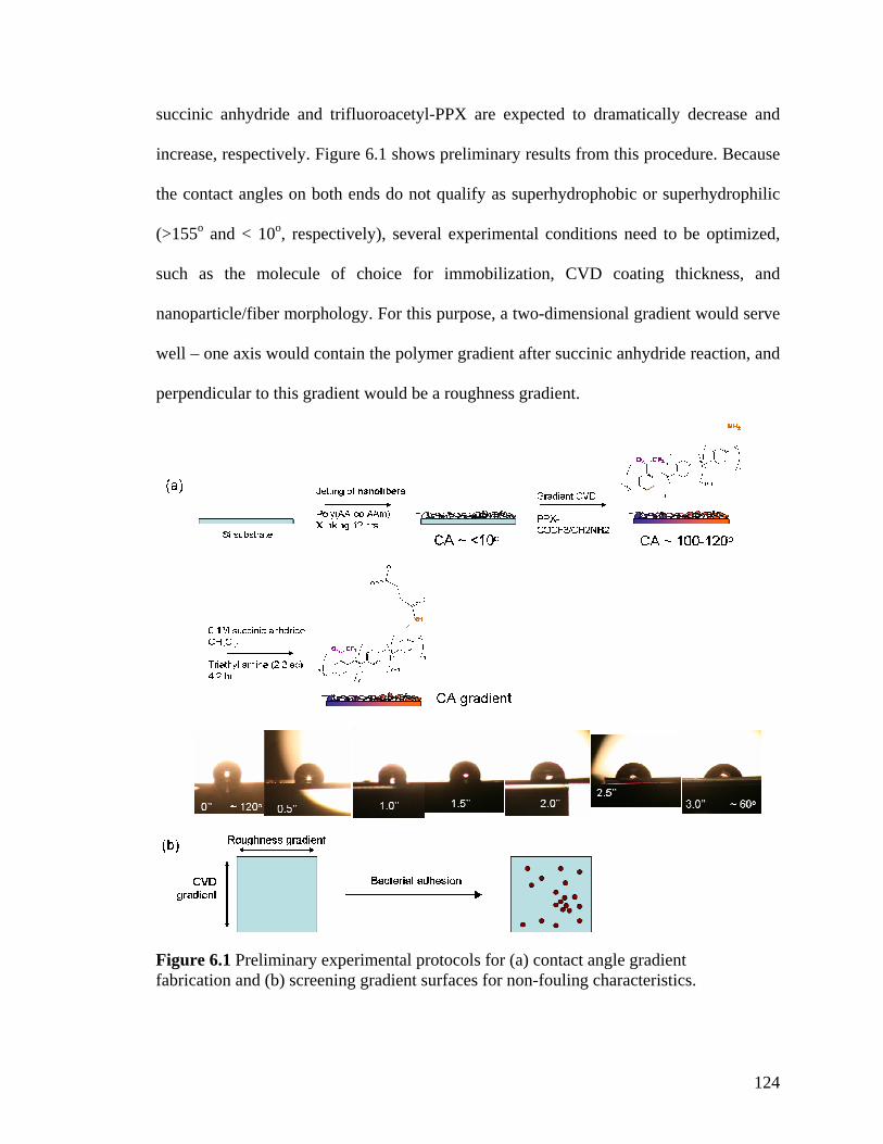
124
Figure 6.1 Preliminary experimental protocols for (a) contact angle gradient fabrication and (b) screening gradient surfaces for non-fouling characteristics.
succinic anhydride and trifluoroacetyl-PPX are expected to dramatically decrease and
increase, respectively. Figure 6.1 shows preliminary results from this procedure. Because
the contact angles on both ends do not qualify as superhydrophobic or superhydrophilic
(>155o and < 10o, respectively), several experimental conditions need to be optimized,
such as the molecule of choice for immobilization, CVD coating thickness, and
nanoparticle/fiber morphology. For this purpose, a two-dimensional gradient would serve
well – one axis would contain the polymer gradient after succinic anhydride reaction, and
perpendicular to this gradient would be a roughness gradient.
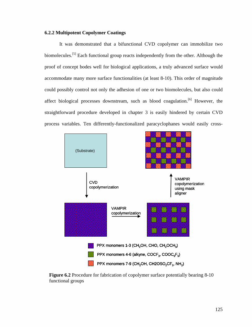
125
CVD copolymerization
VAMPIRcopolymerization
VAMPIRcopolymerizationusing maskaligner
PPX monomers 1-3 (CH2OH, CHO, CH2OCH3)
PPX monomers 4-6 (alkyne, COCF3, COOC5F5)
PPX monomers 7-9 (CH2OH, CH2OSO2CF3, NH2)
(Substrate)
CVD copolymerization
VAMPIRcopolymerization
VAMPIRcopolymerizationusing maskaligner
PPX monomers 1-3 (CH2OH, CHO, CH2OCH3)
PPX monomers 4-6 (alkyne, COCF3, COOC5F5)
PPX monomers 7-9 (CH2OH, CH2OSO2CF3, NH2)
PPX monomers 1-3 (CH2OH, CHO, CH2OCH3)
PPX monomers 4-6 (alkyne, COCF3, COOC5F5)
PPX monomers 7-9 (CH2OH, CH2OSO2CF3, NH2)
(Substrate)
Figure 6.2 Procedure for fabrication of copolymer surface potentially bearing 8-10 functional groups
6.2.2 Multipotent Copolymer Coatings
It was demonstrated that a bifunctional CVD copolymer can immobilize two
biomolecules.[5] Each functional group reacts independently from the other. Although the
proof of concept bodes well for biological applications, a truly advanced surface would
accommodate many more surface functionalities (at least 8-10). This order of magnitude
could possibly control not only the adhesion of one or two biomolecules, but also could
affect biological processes downstream, such as blood coagulation.[6] However, the
straightforward procedure developed in chapter 3 is easily hindered by certain CVD
process variables. Ten differently-functionalized paracyclophanes would easily cross-

126
react in situ. Also, the ratios would be very difficult to control, regardless if a one-source
or two-source CVD was used.
One possible way to bypass such problems is to employ a combination of the
VAMPIR procedure (described in chapter 1) and CVD copolymerization. As shown in
Figure 6.2, a copolymer (3-5 different dimers) is homogeneously deposited onto a
substrate. Following this, a micropatterned PDMS stamp is applied to the substrate, after
which VAMPIR copolymerization is performed, using 3-5 dimers different than that of
the base copolymer. What results is a copolymer surface comprising of 8-10 functional
groups, provided that the pattern features are sufficiently small. By using a mask aligner
to apply a second VAMPIR stamp, another VAMPIR deposition step can be employed,
such that its pattern is misaligned from the first. This procedure could produce a surface
which bears three patterns simultaneously (Figure 6.2), and it would allow the user to
divide the 10-component copolymerization into three steps. Such a process, if
accomplished successfully, could also transform DNA/protein microarrays into highly
advanced and highly selective devices. Efficient bioassays and diagnostic devices rely on
the specific binding of analytes and biomolecules.[7] Thus, the more analytes one can bind
in a specific manner, the more detailed and specific the detection will be. Within each
group of monomers in the VAMPIR pattern (Figure 6.2), one functional group serves as
the binding site, whereas the other two are meant to inhibit adhesion of other molecules.
Also, in gene therapy applications, multiple virus vectors can be immobilized in specific
predefined areas, a necessity for directing tissue regeneration of organs such as bone.[8]
The protocol specified in Figure 6.2 could be used to regenerate organ tissue and blood
vessels.

127
6.2.3 CVD Copolymer Gradients
The two-source CVD system is as adaptable as the chamber structure. As long as
ports exist in the chamber wall, the user can augment additional hardware into the
system. For example, the two-source system used accommodates an in situ mass
spectrometer, which can be used to gauge the stability and degree of monomer pyrolysis.
However, if the angle between the two existing sources is decreased to 120o instead of
180o, a third source can be installed, allowing for the production of ternary copolymer
gradients. Figure 6.3 illustrates the idea with a possible outcome. One limitation of the
existing equipment has been a lack of in situ imaging. XPS would become too
cumbersome for examining samples over a large 2-dimensional area. FTIR or Raman
imaging would also be an important supplement to a 3-source deposition system.
Further expansion of the available range of gradient concentrations will be
another area of further study. Although CVD parameters control the gradient slope with
ease, a decrease in gradient slope will also be valuable. However, some hurdles block the
facile decrease of polymer gradient slope. One hurdle is the fluctuation of polymer
gradient composition. Decreasing the polymer gradient slope to 1.5 inches may be
possible by decreasing the system mean free path, as suggested in Chapter 5. Also, if a 3-
source CVD system is employed, one could conceivably load an identical monomer into
two sources, with a different monomer loaded into the third source. Such a protocol may
offset the aforementioned obstacle. In any event, the immobilized biomolecular
gradient(s) have an effectively greater slope than the base polymer gradient, due to steric
hindrances of immobilized biomolecules.

128
While the work described illustrates the immobilization of a biomolecular
gradient, CVD polymer gradients can be used as a platform for other types of gradients.
If a hydrophilic molecule selectively reacts with one of the gradient components, a
contact angle gradient would result. Also, a binary and/or ternary gradient can be used in
high-throughput combinatorial experiments. Rather than depositing homogeneous
copolymer compositions in a serial manner, one copolymer gradient can simultaneously
screen for cellular responses towards many different surface compositions. Most
importantly, the gradient can potentially induce cell chemotaxis and differentiation. The
ability to deposit high-slope gradients would greatly benefit cell chemotaxis studies. As
an application, one could immobilize a gradient of morphogens, which is necessary for
tissue development.[9] The gradient would be useful post-surgery in accelerating patient
recovery and preventing autoimmune responses towards implants.
Figure 6.1 Overhead-view schematic of a potential three-source CVD system.

129
References
[1] J. Lahann, Polym. Int. 2006, 55, 1361.
[2] J.A. Lee, T.J. McCarthy, Polymer Preprints 2007, 48, 464.
[3] W.R. Dolbier Jr., M.A. Asghar, H.Q. Pan, L. Celewicz, J. Org. Chem. 1993, 58, 1827.
[4] W.R. Dolbier Jr., P. Xie, L. Zhang, W. Xu, Y. Chang, K.A. Aabboud, J. Org. Chem.
2008, 73, 2469.
[5] Y. Elkasabi, H.Y. Chen, J. Lahann, Adv. Mater. 2006, 18, 1521.
[6] A.K. Bajpai, J. Mater Sci. Mater. Med. 2008, 19, 343.
[7] H. Tani, K. Maehana, T. Kamidate, Anal. Chem, 2004, 76, 6693-6697.
[8] R.M. Schek, E.N. Wilke, S.J. Hollister, P.H. Krebsbach, Biomater. 2006, 27, 1160.
[9] J.B. Gurdon, P.Y. Bourillot, Nature 2001, 413, 797.

130
APPENDICES

131
APPENDIX A
Protocol for Escherichia coli Adhesion onto Poly(p-xylylene) Coated Surfaces
The author would like to acknowledge Daniel Smith and Soon-Gong Choi for conducting the bacterial adhesion experiments.
Using CVD-coated 8-well glass slides 1. Sterilize in 95% EtOH for >5 minutes. Sonicate briefly above each well 2. Cells grown in liquid culture
a. Spin down 1mL of saturated overnight culture at 16,000g for 1 minute. b. Wash pellet with 1mL of PBS pH 7.4 by flicking and pipetting up/down. c. Spin down again at 16,000g 1 minute. d. Resuspend pellet in 1mL of PBS by flicking and pipetting up/down. e. Dilute to 1OD with PBS.
3. Cells grown on a YESCA plate a. Pull cells from plate and resuspend in 1mL of PBS. b. Wash with 1mL of PBS pH 7.4 by flicking and pipetting up/down. c. Spin down again at 16,000g for 1 minute. d. Resuspend pellet in 1mL of PBS by flicking and pipetting up/down. e. Dilute to 1OD with PBS
4. Place 20uL of cells suspensions on plate and incubate at room temperature for 2 hours (or vary).
5. Wash plate by dropping into 50mL of PBS in a large wash tray. 6. Wash 5 minutes by shaking at ‘5’ speed. Remove PBS and wash 2 more times 7. Put plates on a blotting paper and remove excess solutions. 8. Let plate dry >30 minutes at 37 oC. 9. OPTIONAL: Heat fixation. Wave plate over flame for a few seconds to dry it.
Staining:
DAPI 1. Add 200µL of 200X DAPI stain to 40mL of PBS 2. Drop plates in stain and cover. Incubate for 5 minutes on benchtop. 3. Wash 3X in 50mL of PBS for 5 minutes. Keep covered 4. To view slide (should be some liquid left) cover with a slip and view with DAPI
filter set Crystal Violet
1. Add 50mL of 1% Crystal Violet (CV) to large wash tray. 2. Drop plates into CV and stain for 1 hour. Keep covered 3. Wash 3X in 50mL of PBS for 5 minutes. 4. Take a picture
Live/Dead Assay (Cells in suspension)
1. Add 6µL of Component A to 2mL of MilliQ water to make 2X staining solution.

132
2. Take OD 670 of cells used in above solution 3. Dilute to OD670 of 0.12 in PBS 4. Add 100µL of cells into a 96 well plate and add 100µL of staining solution. 5. Incubate the sample in the dark for 15 minutes. 6. Excite at 485 and Read from 500 to 700 in 5 nm Steps using a 495 Cutoff 7. Be sure to duplicate samples and do a buffer control
(On a plate) 1. After drying dilute 2X staining solution to 1X with PBS 2. Add 50µL of 1X staining solution to each depression. 3. Incubate in the dark for 15 minutes. 4. Remove ~45µL of solution with a pipette 5. Add coverslip and view with fluorescent microscope
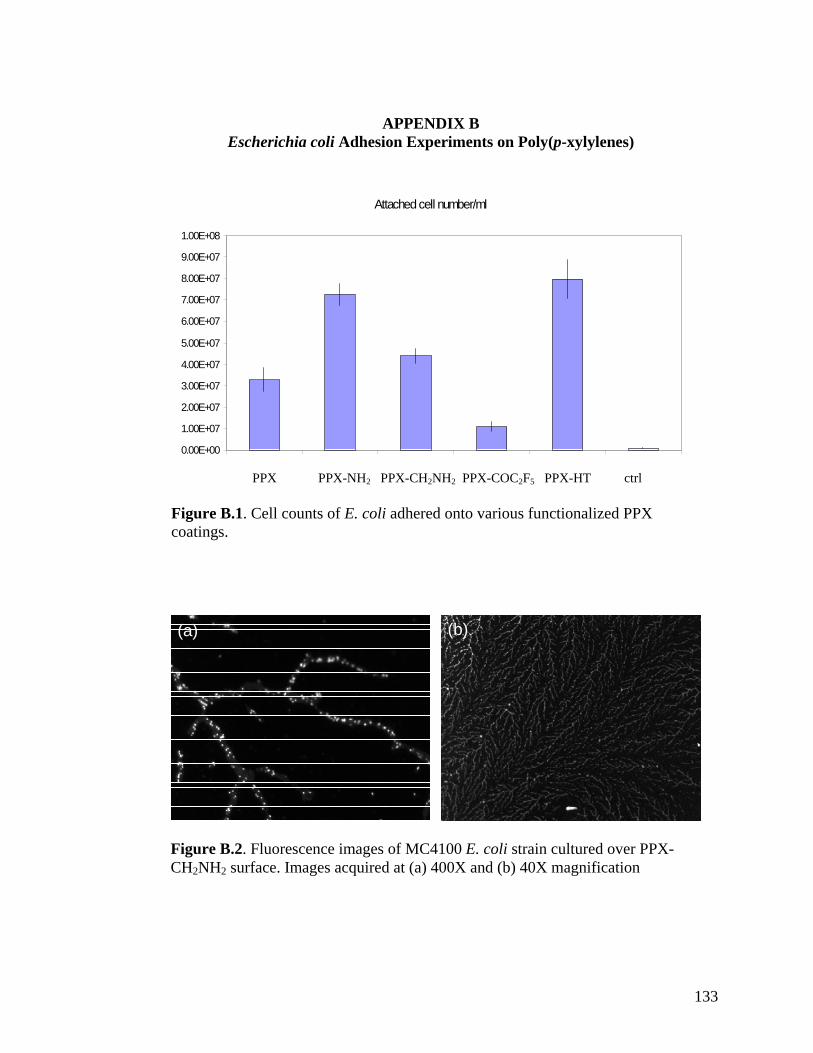
133
Attached cell number/ml
0.00E+00
1.00E+07
2.00E+07
3.00E+07
4.00E+07
5.00E+07
6.00E+07
7.00E+07
8.00E+07
9.00E+07
1.00E+08
PPX PPX-NH2 PPX-CH2NH2 PPX-COC2F5 PPX-HT ctrl Figure B.1. Cell counts of E. coli adhered onto various functionalized PPX coatings.
(a) (b)
Figure B.2. Fluorescence images of MC4100 E. coli strain cultured over PPX-CH2NH2 surface. Images acquired at (a) 400X and (b) 40X magnification
APPENDIX B
Escherichia coli Adhesion Experiments on Poly(p-xylylenes)

134
Figure B.3 Fluorescence images (40X magnification) of LSR11 E. coli strain cultured over (a) PPX-COC2F5 and (b) PPX-HT surfaces.
(a)
(b)
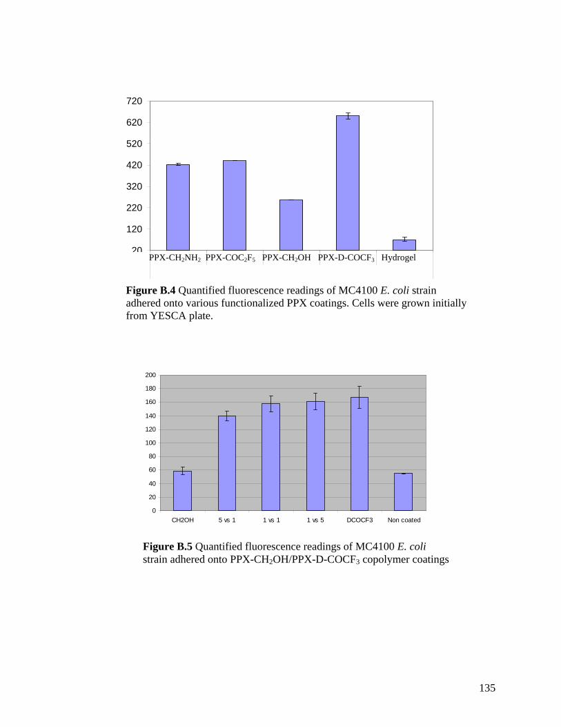
135
20
120
220
320
420
520
620
720
PPX-CH2NH2 PPX-COC2F5 PPX-CH2OH PPX-D-COCF3 Hydrogel Figure B.4 Quantified fluorescence readings of MC4100 E. coli strain adhered onto various functionalized PPX coatings. Cells were grown initially from YESCA plate.
0
20
40
60
80
100
120
140
160
180
200
CH2OH 5 vs 1 1 vs 1 1 vs 5 DCOCF3 Non coated
Figure B.5 Quantified fluorescence readings of MC4100 E. coli strain adhered onto PPX-CH2OH/PPX-D-COCF3 copolymer coatings