multifunctional access box with cip safety over...
TRANSCRIPT
Installation Instructions
Original Instructions
Multifunctional Access Box with CIP Safety over EtherNet/IP Catalog Numbers 442G-MABH-x, 442G-MABxB-Ux-x, 442G-MABE1
The products that are shown on this document conform with the Essential Health and Safety Requirements (EHSRs) of the European Machinery Directive.
Declaration of Conformity and certification: www.rockwellautomation.com/certification/overview.page
Additional Resources
You can view or download publications at http://www.rockwellautomation.com/literature/. To order paper copies of technical documentation, contact your local Allen-Bradley® distributor or Rockwell Automation® sales representative.
The Guardmaster® 442G Multifunctional Access Box with CIP Safety™ over EtherNet/IP™ implements the CIP Safety protocol to enable integration into a safety-control system. The device provides guard position monitoring and lock monitoring in accordance with ISO 14119.
General ConsiderationsInstallation must be in accordance with the present manual and must be performed by qualified personnel exclusively. The Access Box guard locking switch system is intended to be part of the safety-related control system of a machine. Before installation, a thorough risk assessment must be performed to determine whether the specifications (see page 8) of this device are suitable for all foreseeable operational and environmental characteristics of the application.
ATTENTION: Read this document and the documents that are listed in the Additional Resources section about installation, configuration, and operation of this equipment before you install, configure, operate or maintain this product. Users are required to familiarize themselves with the installation and wiring instructions and the requirements of all applicable codes, laws, and standards including:
• ISO 14119: Interlocking devices that are associated with guards; • ISO 14120: General requirements for the design, construction,
and selection of guards;• ISO 13857: For the positioning of safeguards;• ISO 13855: For the calculation of minimum (safe) distances;• For functional safety, either IEC 62061 or ISO 13849-1 and
ISO 13849-2;• And other applicable standards.Activities including installation, adjustments, putting into service, use, assembly, disassembly, and maintenance are required to conduct suitably trained personnel in accordance with the applicable code of practice.
This device is intended to be part of the safety-related control system of a machine. Improper selection or installation of the device affects the integrity of the safety-related control system. First, a risk assessment must be performed to determine whether the specifications of this device are suitable for all foreseeable operational and environmental characteristics of the application. Use appropriate screws, bolts, or nuts that are fitted by tools to mount the switch and actuators to avoid the risk of tampering. Do not over torque the mounting hardware.
Management controls, working procedures, training, and extra protective measures should be used to minimize the motivation to defeat and to manage the use and availability of spare actuators.
Personnel injury or death, property damage, or economic loss can result if this document and applicable codes, laws, and standards are not followed.
Resource Description
多功能通道锁 442G-IN001A-ZH-P
Caja de acceso multifuncional instrucciones de instalación 442G-IN001A-ES-P
Caixa de acesso multifuncional instruções de instalação 442G-IN001A-PT-P
多機能アクセスボックス インストレーションインストラクション
442G-IN001A-JA-P
Multifunktions-Zugangsbox – Installationsanleitung 442G-IN001A-DE-P
"Notice d'installation de la gâche d'accès multifonctions" 442G-IN001A-FR-P
Istruzioni per l’installazione 442G-IN001A-IT-P
多功能存取盒安裝指南 442G-IN001A-ZC-P
Multifunctional Access Box User Manual 442G-UM001B-EN-P
Industrial Automation Wiring and Grounding Guidelines, publication 1770-4.1
Provides general guidelines for installing a Rockwell Automation® industrial system.
Product Certifications website, http://www.rockwellautomation.com/products/certification
Provides declarations of conformity, certificates, and other certification details.
Multifunctional Access Box with CIP Safety over EtherNet/IP
Environmental ProtectionLasting and correct safety function requires that the system must be protected against debris (filings, shavings, and so on), which can become lodged in the locking and handle modules. For this purpose, a suitable installation position should be selected.
Power Supply Requirements
Electrical Connection
Connections on Bus ModuleThis section describes the power connectors, EtherNet/IP connectors, and recommended cables.
Connections on Bus Module
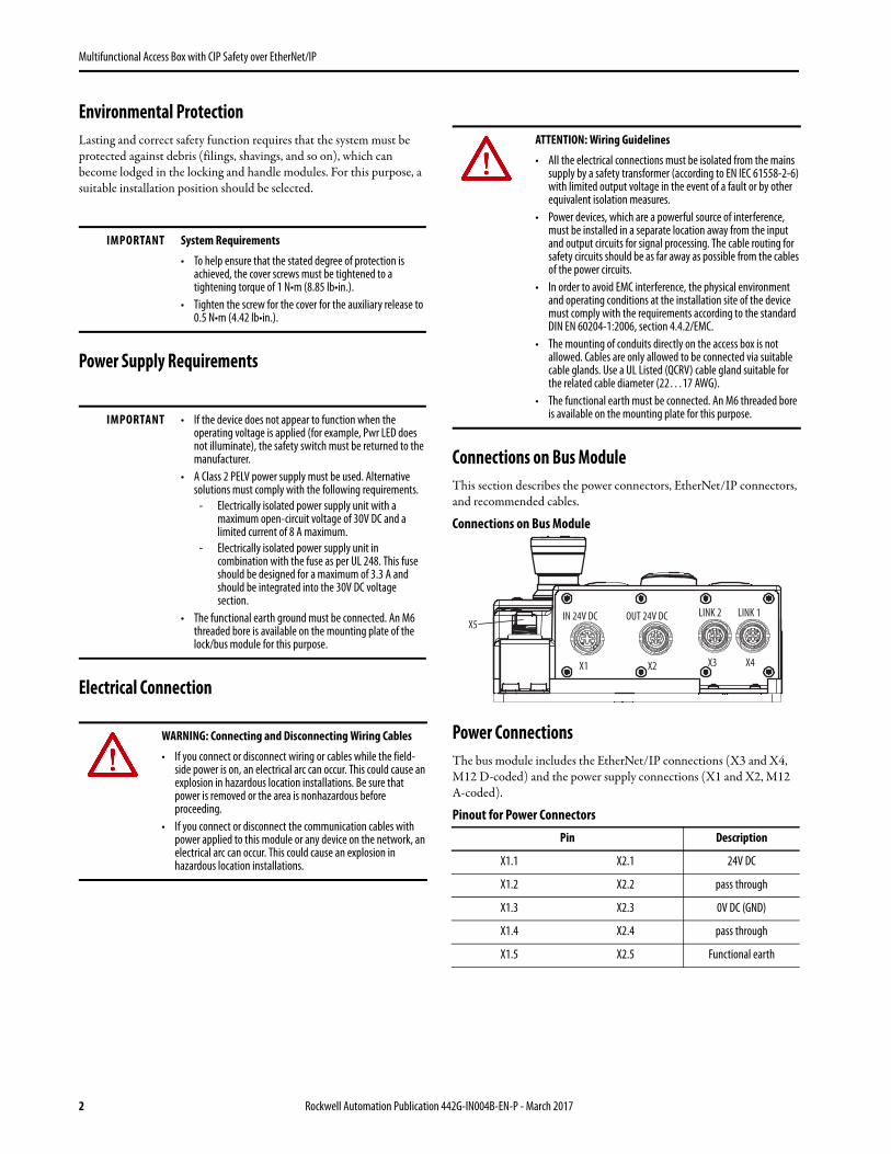
Power ConnectionsThe bus module includes the EtherNet/IP connections (X3 and X4, M12 D-coded) and the power supply connections (X1 and X2, M12 A-coded).
Pinout for Power Connectors
IMPORTANT System Requirements
• To help ensure that the stated degree of protection is achieved, the cover screws must be tightened to a tightening torque of 1 N•m (8.85 lb•in.).
• Tighten the screw for the cover for the auxiliary release to 0.5 N•m (4.42 lb•in.).
IMPORTANT • If the device does not appear to function when the operating voltage is applied (for example, Pwr LED does not illuminate), the safety switch must be returned to the manufacturer.
• A Class 2 PELV power supply must be used. Alternative solutions must comply with the following requirements.
- Electrically isolated power supply unit with a maximum open-circuit voltage of 30V DC and a limited current of 8 A maximum.
- Electrically isolated power supply unit in combination with the fuse as per UL 248. This fuse should be designed for a maximum of 3.3 A and should be integrated into the 30V DC voltage section.
• The functional earth ground must be connected. An M6 threaded bore is available on the mounting plate of the lock/bus module for this purpose.
WARNING: Connecting and Disconnecting Wiring Cables
• If you connect or disconnect wiring or cables while the field-side power is on, an electrical arc can occur. This could cause an explosion in hazardous location installations. Be sure that power is removed or the area is nonhazardous before proceeding.
• If you connect or disconnect the communication cables with power applied to this module or any device on the network, an electrical arc can occur. This could cause an explosion in hazardous location installations.
ATTENTION: Wiring Guidelines
• All the electrical connections must be isolated from the mains supply by a safety transformer (according to EN IEC 61558-2-6) with limited output voltage in the event of a fault or by other equivalent isolation measures.
• Power devices, which are a powerful source of interference, must be installed in a separate location away from the input and output circuits for signal processing. The cable routing for safety circuits should be as far away as possible from the cables of the power circuits.
• In order to avoid EMC interference, the physical environment and operating conditions at the installation site of the device must comply with the requirements according to the standard DIN EN 60204-1:2006, section 4.4.2/EMC.
• The mounting of conduits directly on the access box is not allowed. Cables are only allowed to be connected via suitable cable glands. Use a UL Listed (QCRV) cable gland suitable for the related cable diameter (22…17 AWG).
• The functional earth must be connected. An M6 threaded bore is available on the mounting plate for this purpose.
Pin Description
X1.1 X2.1 24V DC
X1.2 X2.2 pass through
X1.3 X2.3 0V DC (GND)
X1.4 X2.4 pass through
X1.5 X2.5 Functional earth
X1 X4X3X2
IN 24V DC LINK 1 LINK 2 OUT 24V DCX5
2 Rockwell Automation Publication 442G-IN004B-EN-P - March 2017

Multifunctional Access Box with CIP Safety over EtherNet/IP
Recommended Power Cables
1 Replace -2 (2 m (6.6 ft)) with -5 (5 m (16.4 ft)) or -10 (10 m (32.8 ft)) for additional standard cable lengths.
EtherNet/IP ConnectionsPinout for EtherNet/IP Connectors
Sample EtherNet/IP Cables
1 Replace -2 (2 m (6.6 ft)) with -5 (5 m (16.4 ft)) or -10 (10 m (32.8 ft)) for additional standard cable lengths.
MountingThe access box can be mounted on hinged or sliding doors. Use appropriate screws, bolts, or nuts that are fitted by tools to mount the lock/bus module and handle assembly to avoid tampering. Do not over-torque the mounting hardware.
Installation Example for Guard Door That Is Hinged on the Right
X1 X2
Power supply connector assignment. Connectors X1 and X2, M12 A-coded.
Description Cat. No.
Micro Straight Female to Flying Leads Cordset 889D-F4AC-2 1
Micro Straight Male to Flying Leads Cordset 889D-M4AC-2 1
Micro Right Angle Female to Flying Leads Cordset 889D-R4AC-2 1
Micro Right Angle Male to Flying Leads Cordset 889D-E4AC-2 1
Pin Description
X3.1 X4.1 TxD+
X3.2 X4.2 RxD+
X3.3 X4.3 TxD-
X3.4 X4.4 RxD-
X3/X4
EtherNet/IP connector assignment. Connectors X3 and X4, M12 D-coded.
Description Cat. No.
M12 D-coded straight to RJ45 patchcord 1585D-M4UBJM-2 2
M12 D-coded straight to flying leads cordset 1585D-M4UB-2 2
M12 D-coded straight to M12 straight patchcord 1585D-M4UBDM-2 2
M12 D-coded right angle to M12 right angle patchcord 1585D-E4UBDE-2 2
Pin Description
12
43
1 2
4 3
1 2
4 3
ATTENTION: With two-wing hinged guard doors, one of the two guard door wings must also be latched mechanically. For example, use a rod latch (Item) or a double-door latch (Bosch Roxroth) for this purpose.
TIP For easier installation, it is recommended that the handle assembly is mounted to the guard door before the silver handle is attached to the handle assembly.
Rockwell Automation Publication 442G-IN004B-EN-P - March 2017 3

Multifunctional Access Box with CIP Safety over EtherNet/IP
Indicator Lens Set InstallationInstalling Lens Cover
Removing Lens Cover
Preparing the Escape ReleaseThe escape release is used to open a locked safety guard from inside the safe-guarded area without tools.
The system enters into a latching fault when the escape release is actuated. Note: A latching fault may not occur if the escape release is actuated slowly.
To clear the fault, open the guard and turn on the LockSequenceFaultUnlatch input signal.
Use the following table to determine if the extended shaft is needed (442G-MABASHFT ordered separately) to prepare the escape release for smaller or larger profiles.
Determining the Required Shaft Length [mm (in.)]
1 The extended shaft (442G-MABASHFT) must be ordered separately.
1 2 3
90 °
Click!
Color Lens
1 2
IMPORTANTIMPORTANT The guard door must be in the open position to clear a latching fault.
IMPORTANT The escape release is not a safety function.The machine manufacturer must select and use a suitable release according to the risk assessment. The correct operation must be checked at regular intervals.
Profile Width
Length Required forActuation Shaft
Shaft Required 1 Necessary Work Steps
Without Plates
With Plates 4 (0.16) each
D D+13 D+21
30 (1.18)
43 (1.69) 51 (2.0) Standard shaft Shorten to required length
40 (1.57)
53 (2.09) 61 (2.4) Standard shaft or extended shaft
Without mounting plates: None With mounting plates: Shorten extended shaft and protective sleeve to required length
45 (1.77)
58 (2.28) 66 (2.6) Extended shaft Shorten extended shaft and protective sleeve to required length
50 (1.97)
63 (2.48) 71 (2.79) Extended shaft Shorten extended shaft and protective sleeve to required length
4 Rockwell Automation Publication 442G-IN004B-EN-P - March 2017

Multifunctional Access Box with CIP Safety over EtherNet/IP
Example with Mounting Plates [mm (in.)]
Shortening the Extended Actuation Shaft [mm (in.)]
Mounting the Escape ReleaseMounting Escape Release
1. Attach door handle
2. Insert actuation shaft. The locking ring A must be in contact with the escape release B.
3. Tighten setscrew to 2 N•m (17.7 lb•in)
4. Slide protective sleeve over actuation shaft
Handle ConfigurationThe unique-coded handle assembly must be assigned to the locking module before the system is functional.
1. Insert bolt tongue in the locking module.
2. Apply operating voltage to the device.
3. Programming begins when the State status indicator flashes (1 Hz). After approximately 60 seconds, the State status indicator turns off.
4. To complete the configuration, turn on input signal LockSequenceFaultUnlatch to activate the new code. Alternatively, remove the power from the access box for a few seconds.
4(0.16)
D
10(0.39)
3.5(0.14)
4(0.16) 58.5
(2.30)
Handle module
Mounting plates
Escape release assembly
55.5(2.19)
D + 13.5 (0.53)(+ 4 (0.16)
182(7.16) D + 3 (0.12)
(+ 4 (0.16)
8(0.32)
Ø 11.2 (0.44) Ø 14 (0.55)
Actuation shaftProtective sleeve
per Plate)per Plate)
ATTENTION: The escape release must ONLY be accessible from inside the safeguarded area. The installation must not allow access to the escape release from outside the safeguarded area.
IMPORTANT The system is in a safe state (input signals GuardClosed, GuardInterlocked, and GuardLocked are turned off) during handle configuration.
1
3 24
A
B
Rockwell Automation Publication 442G-IN004B-EN-P - March 2017 5

Multifunctional Access Box with CIP Safety over EtherNet/IP
Connecting an Enabling SwitchA standard enabling switch (440J-N21TNPM or equivalent) can be attached to connector X5 on select models.
Recommended Cordset
1 Replace -2 (2 m (6.6 ft)) with -5 (5 m (16.4 ft)) or -10 (10 m (32.8 ft)) for additional standard cable lengths.
Mechanical Function Test
Electrical Function TestPerform following steps.
1. Switch on operating voltage.
2. Close all safety guards and insert the bolt actuator into the locking module. For Power to Lock versions, activate guard locking.• The machine must not start automatically.• It must not be possible to open the safety guard.• The State status indicator and the Lock status indicator are
illuminated continuously.
3. Use the control system to start the machine.• It must not be possible to open the guard door as long as the
machine is running.
4. To stop the machine and unlock the door, use the control system.• The safety guard must remain locked until there is no longer
any risk of injury.• It must not be possible to start the machine as long as the guard
locking is deactivated.• It must be possible to open the safety guard.
Repeat steps two through four for each safety guard.
Connect the Multifunctional Access Box to the EtherNet/IP NetworkThe MAB has two Ethernet ports that support 10/100/1000 Mbps. Connect a CAT 5e or CAT 6 Ethernet cable with M12 connectors to the Ethernet ports (X3 and X4) on the underside of the Bus module.
For information on how to select the proper cable, see Guidance for Selecting Cables for EtherNet/IP Networks, publication ENET-WP007-EN-P.
You also need to configure an Ethernet driver for your workstation by using RSLinx® Classic Software. See Add a Driver in the RSLinx Classic software Help.
Inspection and ServicePeriodically check the correct operation of the switching function. Also check for signs of abuse or tampering. Inspect the switch casing for damage. Check the safe function of the device particularly after any of the following:
• Set-up work• The installation or replacement of any hardware• An extended period without any use• A fault condition
IMPORTANT The locking module disables the code for the previous handle assembly if configuration is conducted for a new handle assembly. A disabled handle assembly can be configured again only after a third handle assembly has been configured.
Description Color Pinout
Recommended Cordset 889D-M4AC-21
Micro straight male to flying leads cordset
BrownSafety A
Blue
WhiteSafety B
Black
IMPORTANT It must be possible to insert the bolt actuator in the locking module. To check, close the safety guard several times and actuate the guard door handle.
If available, check the function of the escape release. It must be possible to operate the escape release from the inside without excessive force (approximately 40 N (8.99 lff )).
ATTENTION: The escape release must ONLY be accessible from inside the safeguarded area. The installation must not allow access to the escape release from outside the safeguarded area.
5 N/A
4 Safety B3 Safety A
1 Safety A
2 Safety B
WARNING: Safety components perform a personal protection function. They must not be bypassed, removed, or otherwise rendered ineffective. The switching operation is only allowed to be triggered by the intended handle assembly that is properly mounted to the safety guard.
ATTENTION: If there is a malfunction or damage to the product, attempts at repair shall not be made. The unit should be replaced or alternative safeguarding shall be implemented before machine operation is allowed.
6 Rockwell Automation Publication 442G-IN004B-EN-P - March 2017

Multifunctional Access Box with CIP Safety over EtherNet/IP
Dimensions [mm (in.)]
10(0.39)
135(5.31)
170(6.69)
30(1.18)
17.5(0.69)
15(0.59)
10(0.39)
32 (1.26)
12(0.47)
IN 24V DC OUT 24V DC LINK 1LINK 2
Act2
LnkAct
NetMod
Pwr
11
Lnk2
S6S4
S9
S0
20(0.79)
15(0.59)
10(0.39)
15(0.59)
345(13.58)
20(0.79)
6.5(0.25)
155 (6.10)
6.5 (0.25)
111(4.37)
30(1.18)
21(0.83)
12(0.47)
37 (1.45)
145 (5.71)
130 (5.12)
S7
104(4.09)
113.5(4.47)
83(3.27)
62.5(2.46)
289.3 (11.39)
19.2 (0.75)
40(1.57)
51(2.01)
M20 x 1.5 (0.06) (4x)
4(0.16)
Rockwell Automation Publication 442G-IN004B-EN-P - March 2017 7

Specifications
1 Refer to Electrical Connection—Power Supply Requirements on page 2.2 The risk time is the maximum difference between the time the input status changes and the time the
corresponding bit in the input assembly is turned on.
Safety Ratings
Standards IEC 60947-5-3, EN ISO 13849-1, ISO 14119, UL 508 (evaluated for risks of electrical shock and fire; only suitable for NFPA 79 applications)
Safety Classification Type 4 interlocking device with guard locking and high-coded RFID actuators according to ISO 14119
Functional Safety Data
PL e, Cat. 4 (according to ISO 13849-1)
MTTFd Monitoring of guard locking 746 years
Control of guard locking 475 years
Evaluation of emergency stop 787 years
Evaluation of enabling switch 753 years
PFHd Monitoring of guard locking 3.37 x 10⁻⁹
Control of guard locking 4.91 x 10⁻⁹
Evaluation of emergency stop 3.05 x 10⁻⁹
Evaluation of enabling switch 3.05 x 10⁻⁹
B10d: Emergency stop 1.0 x 10⁵
Enabling switchAccording to manufacturer's specifications
Mission time 20 years
Certifications cULus (UL 508) and CE Marked for all applicable EU directives
Safety Outputs CIP Safety
Operating Characteristics
Torque Settings, maximum1 N•m (8.85 lb in.) lock module cover screws (6x); 0.5 N•m (4.42 lb in.) manual release locking screw; 2 N•m (17.70 lb in.) handle set screw (handle and escape release)
Holding Force Fzh (ISO 14119) 2000 N
Locking Bolt Alignment Tolerance Horizontal: ± 4 mm (0.16 in.); Vertical: ± 5 mm (0.2 in.)
Operating Voltage Class 2 PELV 24V DC +10/-15% required1
EMC Protection Requirements In accordance with EN 61000-4 and DIN EN 61326-3-1
Current Consumption, maximum 500 mA
Operating Characteristics (continued)
Power Connector Rating 4 A (IEC 61076-2-101:2013) maximum value
External Fuse Minimum 1 A, slow-blow
EMC Protection Requirements In accordance with EN 61000-4 and DIN EN 61326-3-1
Risk Time (per IEC 60947-5-3)2
EStopEnabling switchGuard positionBolt positionGuard locking
100 ms100 ms250 ms250 ms250 ms
Switching Frequency, maximum 1 Hz
Insulation Voltage Ui (IEC 60947-1) 75V
Impulse Withstand Voltage Uimp 0.5 kV
Pollution Degree (IEC 60947-1) 3
Manual Release Built in (ISO 14119)
Mechanical Life 1,000,000 operations
Environmental
Ambient Temperature at UB = DC 24V -20…+55°C (-4…+131°F)
Storage Temperature [C (F)] -20…+65° (-4…+149°)
Enclosure Rating IP54
Operating Humidity 5…80% relative
Vibration/Shock IEC 60068-2-27 30 g (1.06 oz), 11 ms/IEC 60068-2-6 10…55 Hz
Physical Characteristics
WeightLock/bus assembly on mounting plate 3.6kg (7.9lb), handle assembly on mounting plate 1.2kg (2.6lb), escape release 500g (17.6 oz)
MaterialsGlass fiber reinforced plastic, nickel-plated die-cast zinc, anodized aluminum handle, stainless steel, powder-coated sheet steel
Allen-Bradley, Rockwell Automation, and Rockwell Software are trademarks of Rockwell Automation, Inc.
Trademarks not belonging to Rockwell Automation are property of their respective companies.
Rockwell Otomasyon Ticaret A.Ş., Kar Plaza İş Merkezi E Blok Kat:6 34752 İçerenköy, İstanbul, Tel: +90 (216) 5698400
Rockwell Automation maintains current product environmental information on its website athttp://www.rockwellautomation.com/rockwellautomation/about-us/sustainability-ethics/product-environmental-compliance.page.
Publication 442G-IN004B-EN-P - March 2017 10002217114 Ver 01125244-02-03/17
Copyright © 2017 Rockwell Automation, Inc. All rights reserved. Printed in the U.S.A.