multicolour led rocker switch panel
TRANSCRIPT

Powering systems - Empowering designers
428RSP Series
Design Specifications
• Shock: Mil Std 202 Method 213 test condition 1.
• Vibration: Tested to Lloyds Registered approval vibration test 2.
• Ingress Protection: IP40.
• PCB characteristics: UL94V-0.
• UVB certification: UVB 400 hours.
Key Features
• LED color configuration, choose from a 64-color palette via E-Logic.
• Each LED can be configured with up to four unique system-status colors.
• Interchangeable cams to create different switch modes.
• Laser-etched actuators (customer-specified legends).
• Rocker switch uses optical interrupters (no contacts).
• Panel assembly is weather resistant and the board is conformal coated. External use requires additional physical protection to suit application.
• LEN value 17 to 25.
Introduction
The E-Plex 428RSP series; a programmable, multi-color LED, rocker switch panel designed to operate within an E-Plex system. This innovative new product incorporates independently controlled LED’s, allowing custom-configured color selection on a per LED basis. Via E-Plex software, each LED is capable of being configured to produce up to 64 unique colors without the need for special ordering or assembly.
The 428RSP utilizes optical interrupters to create a switch output, which means there are no electrical contacts within the switch. The 428RSP provides interchangeable cams, including 1 & 2 position momentary, 2 & 3 position stationary and 2 position momentary / 1 position stationary switches. These cams are designed on a simple snap-in platform that allows for easy and inexpensive assemblies and modifications. In addition, switch banks greater than eight positions can be combined by dovetailing multiple units together.
Multicolour LED Rocker Switch Panel

Powering systems - Empowering designers
428RSP Series
Description Minimum Nominal Maximum
Operating Voltage 10 VDC 12 / 24 VDC 32 VDC
Operating Current, noE-Plex loads
75 mA — 350 mA
Electrical Specifications
Wiring Specifications
Physical SpecificationsDescription Color Intensity
Visible Lighting (without actuator installed)
Red 1500 ~ 2100 mcd
Green 4200 ~ 5800 mcd
Blue 1100 ~ 1500 mcd
Housing UL 94 V-0 ABS injection molded
CAM, Arm, Arm Housing UL 94 V-0 Nylon
Arm Spring SUS304
Actuator Lexan®, laser etched with clear coat
Actuator Guard UL 94 V-0 ABS injection molded
Operating Temperature -20°C to 60°C
Storage Temperature -40°C to 85°C
Operating Humidity 0% to 100% (condensing)
Weight (8 position) 0.375 lb (170 g)
Endurance Tested to 100,000 cycles
Pin # 1 2
Description E-Plex Data Bus + E-Plex Data Bus –
Inputs & Outputs I/O I/O
Recommended Wire Gauge
16AWG (1.3mm) 16AWG (1.3mm)
Terminal Connector
Tin-plated male 0.250” quick-connect tabs
Tin-plated male 0.250” quick-connect tabs
Mating Connector
0.250” female spade terminal
0.250” female spade terminal
E-Plex +
E-Plex –

Powering systems - Empowering designers
428RSP Series
Dimensional Mounting Diagram
Mounting SpecificationsIn order to mount the 428RSP, the panel opening cut out needs to fall within the minimum and maximum allowances, see the 4-switch dimensional drawings below to determine.
Recommended hole cutout: length of 4.15” (105.41mm) and a width of 1.90” (48.26mm). For each additional unit, add 1.00” (25.4mm) to the length.
Maximum panel thickness is 0.35” (8.89mm), for rocker switch assembly to lock into place.
Allow for additional space behind the assembly for wiring of quick connects.
115.2mm [4.54”]
47.75mm[1.88”]
R 6.35mm [0.25”]
10.16mm[0.40”]
20.32mm[0.80”]
24.89mm[0.98”]
105.2mm [4.14”]
37.08mm[1.46”]
60.96mm[2.40”]

Powering systems - Empowering designers
428RSP Series
STEP 1 STEP 2
Choose between 4 to 8 switch-es in the bank.
Choose cam option for each required switch in the bank, starting from left most, front face as switch #1.
Example:A 4-switch bank is specified as code “ 4 ”
CODE DESCRIPTION
A 1-position momentary
B 2-position momentary
C 2-position stationary
D 3-position stationary
E 2-position stationary, 1-position momentary
Positive lens provides LED lighting around the symbol.
Negative lens provides LED lighting through the symbol only.
Part Number Builder (1 of 2):The example below indicates a 428RSP with 8 rocker switches, with switch 1 (left most, front face of the module, E-Plex terminal side) having a 2-position stationary cam, switch 2 having a 1-position momentary cam, switch 3 having a 2-position momentary cam, switch 4 having a 2-position momentary cam, switch 5 having a 3-position stationary cam, switch 6 having a 1-position momentary cam, switch 7 having a 3-position stationary cam, switch 8 having a 2-position stationary cam.
Use the table below to specify your 428RSP switch and CAM characteristics. Contact Airpax ED&D to specify legend / icon engraving and face guard options. Switch bank housings are modular, and can be combined into “one housing assembly”. An E-Plex connection is required for each switch bank ordered.
Legends can be laser-etched into the face plate with either a positive or negative lens. You can have two positive lens, two negative lens, no lens at all (blank), or a combination there of on any switch. Contact the factory for additional legends and for custom designs. LED colors are specified via the E-Logic software.
1 2
428RSP - Switc
h 1
Switch 1
Switch 1
Switch 1
Switch 1
Switch 1
Switch 1
Switch 1
- - - - - - - -8 C A B B D A D C

Powering systems - Empowering designers
428RSP Series
STEP 3 Choose between normal and narrow button face
STEP 4 Select from the “Legends” on pages 6 and 7 to set the upper legend symbol
STEP 5 Upper legend, choose between “P” for positive lens, “N” for negative lens, “B” for blank / none
STEP 6 Select from the “Legends” on pages 6 and 7 to set the lower legend symbol
STEP 7 Lower legend, choose between “P” for positive lens, “N” for negative lens, “B” for blank / none
CODE DESCRIPTION
MC0031 Normal size
MC0033 Narrow size (for face guard)
CODE DESCRIPTION
P Positive lens (LED lighting around the symbol)
N Negative lens (LED lighting through the symbol only)
CODE DESCRIPTION
P Positive lens (LED lighting around the symbol)
N Negative lens (LED lighting through the symbol only)
Part Number Builder (2 of 2):The example below indicates how to specify the legends on the 428RSP face plate, with MC0031 being a normal size face, with an upper legend “61” (“anchor up”) positive lens, with a lower legend “62” (“anchor down”) positive lens.
Use steps 3 through 7 below to specify your 428RSP switch face legends / markings. For legends 00 to 02, skip steps 5 and 7. Contact Airpax ED&D to specify face guard options. Switch bank housings are modular, and can be combined into “one housing assembly”. An E-Plex connection is required for each switch bank ordered.
3 4
- - - -MC0031 61 P 62 P
5 6 7

Powering systems - Empowering designers
428RSP Series
1
WIPER
WASHER
BILGE
BRIDGE
COCKPIT
DIMMER
ENTRY
HULL
OVERHEAD
SPOTLIGHT
SYMBOL CODEDESCRIPTION
NONE
INDICATOR STYLE 1
WIPER WITH TEXT
WIPER
WIPER (#1)
WINDSHIELD WASHER / WIPER
WINDSHIELD WASHER
WITH TEXT
WINDSHIELDWASHER
REAR WINDSHIELD
WASHER
DE-FROSTER
HORN
TRIM TAB 1
TRIM TAB 2
MASTER LIGHT SWITCH
(BILGE)
INDICATOR STYLE 2
SYMBOL CODEDESCRIPTION SYMBOL CODEDESCRIPTION
WATER TANK
RIGHT STABILIZER
DEPTH SOUNDER
BATTER-IES
LAMP 01
LAMP 02
LAMP (BRIGHTER)
LAMP (DIMMER)
HIGH BEAM LIGHTS
ANCHOR LIGHTS
RUNNING LIGHTS
LEFT STABILIZER
LOW BEAM LIGHTS
ANCHOR / RUNNINGLIGHTS
MASTER LIGHT SWITCH
(BRIDGE)
MASTER LIGHT SWITCH
(COCKPIT)
MASTER LIGHT SWITCH
(DIMMER)
MASTER LIGHT SWITCH
(HULL)
MASTER LIGHT SWITCH
(ENTRY)
MASTER LIGHT SWITCH
(OVERHEAD)
MASTER LIGHT SWITCH
(SPOTLIGHT)
MASTER LIGHT SWITCH
LIGHTS
GENERATOR
TURN SIGNALS
VENTILATIONFAN / BLOWER
00
01
02
03
04
05
06
07
08
09
10
11
12
13
14
15
16
17
18
19
20
21
22
23
24
25
26
27
28
29
30
31
32
33
34
35
36
37
38
39
40
41
INTERIOR LIGHTS
Legends

Powering systems - Empowering designers
428RSP Series
AFT
FWD
MAIN
OVERHEADAFT
HULLLIGHTS
ENTRYINDIRECT
COCKPITINDIRECT
LIGHTSOVERHEAD
4
3
2
1
ACCY
LOW MEDIUM
HI
FUEL
ENGINE STOP
EMERGENCY START
ENGINEBLOCK HEATER
BILGE PUMP
DRIVE TILT UP
BILGE PUMP (#1)
BILGE PUMP (#2)
ENGINE START
MUTE
MUSIC
ANCHOR w/ MAIN
ANCHOR (UP)
STOP REQUEST
HAZARD WARNING
ACCESSORY (TEXT)
ANCHOR
SPEED CONTROL
(TEXT)
42
43
44
46
47
48
49
50
51
52
53
54
55
56
57
58
59
60
61
62
63
64
70
71
ENGINE SYNC
ELECT
AUTO PILOT
RADAR
THRUSTER MAIN
ELECTRIC (TEXT)
THRUSTER MAIN (TEXT)
AUTO PILOT (TEXT)
RADAR (TEXT)
65
66
67
68
69
ENGINE SYNC (TEXT)
BILGE PUMP (#3)
BILGE PUMP (#4)
BILGE PUMP w/ FWD
BILGE PUMP w/ AFT
BILGE BLOWER
ANCHOR (DOWN)
ANCHOR (UP/DOWN)
TENDER HATCH
TENDER HATCH (TEXT)
72
ENGINE HATCH
ENGINE HATCH (TEXT)
73
CLOSE CLOSE (TEXT)
74
NAV EQUIP
NAVIGATIONAL EQUIPMENT
(TEXT)75
CHART LIGHT
CHART LIGHT (TEXT)
76
LEDLED
(TEXT) 77
ENGINE BAY LIGHTS 78
79
80
81
82
83
LIGHT w/ TEXT “LIGHTS OVER-
HEAD”
LIGHT w/ TEXT “COCKPIT INDI-
RECT”
LIGHT w/ TEXT “ENTRY INDIRECT”
LIGHT w/ TEXT “HULL LIGHTS”
LIGHT w/ TEXT “OVERHEAD AFT”
SYMBOL CODEDESCRIPTION SYMBOL CODEDESCRIPTION SYMBOL CODEDESCRIPTION
Legends
Powering systems - Empowering designers
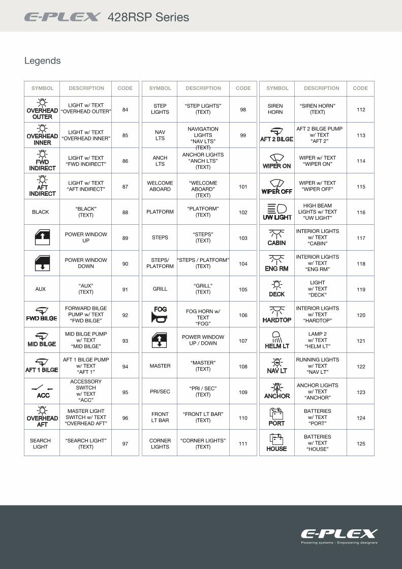
428RSP Series
OVERHEADOUTER
OVERHEADINNER
OVERHEADAFT
FWDINDIRECT
AFTINDIRECT
FWD BILGEFWD BILGE
MID BILGE
AFT 1 BILGE
AFT 2 BILGE
ACCACC
FOGFOG
WIPER ON
WIPER OFFWIPER OFF
UW LIGHTUW LIGHT
CABIN
ENG RM
HARDTOP
DECK
HELM LT
NAV LT
ANCHOR
PORT
HOUSE
84
85
86
87
88
89
90
91
92
93
94
95
96
97
98
99
101
102
103
104
105
106
107
108
109
110
111
112
113
114
115
116
117
118
119
120
121
122
123
124
125
LIGHT w/ TEXT “OVERHEAD OUTER”
LIGHT w/ TEXT “OVERHEAD INNER”
LIGHT w/ TEXT “FWD INDIRECT”
LIGHT w/ TEXT “AFT INDIRECT”
“BLACK” (TEXT)
POWER WINDOW UP
POWER WINDOW DOWN
“AUX”(TEXT)
FORWARD BILGE PUMP w/ TEXT “FWD BILGE”
MID BILGE PUMP w/ TEXT
“MID BILGE”
AFT 1 BILGE PUMP w/ TEXT “AFT 1”
ACCESSORY SWITCH w/ TEXT “ACC”
MASTER LIGHT SWITCH w/ TEXT “OVERHEAD AFT”
“SEARCH LIGHT” (TEXT)
“STEP LIGHTS” (TEXT)
NAVIGATION LIGHTS
“NAV LTS” (TEXT)
ANCHOR LIGHTS “ANCH LTS”
(TEXT)
“WELCOME ABOARD”
(TEXT)
“PLATFORM” (TEXT)
“STEPS” (TEXT)
“STEPS / PLATFORM” (TEXT)
“GRILL”(TEXT)
FOG HORN w/ TEXT
“FOG”
POWER WINDOW UP / DOWN
“MASTER” (TEXT)
“PRI / SEC” (TEXT)
“FRONT LT BAR” (TEXT)
“CORNER LIGHTS” (TEXT)
“SIREN HORN” (TEXT)
AFT 2 BILGE PUMPw/ TEXT “AFT 2”
WIPER w/ TEXT “WIPER ON”
WIPER w/ TEXT “WIPER OFF”
HIGH BEAM LIGHTS w/ TEXT
“UW LIGHT”
INTERIOR LIGHTS w/ TEXT “CABIN”
INTERIOR LIGHTS w/ TEXT
“ENG RM”
LIGHT w/ TEXT “DECK”
INTERIOR LIGHTS w/ TEXT
“HARDTOP”
LAMP 2 w/ TEXT
“HELM LT”
RUNNING LIGHTS w/ TEXT “NAV LT”
ANCHOR LIGHTS w/ TEXT
“ANCHOR”
BATTERIES w/ TEXT “PORT”
BATTERIES w/ TEXT
“HOUSE”
BLACK
AUX
SEARCH LIGHT
STEP LIGHTS
NAV LTS
ANCH LTS
WELCOME ABOARD
PLATFORM
STEPS
STEPS/ PLATFORM
GRILL
MASTER
PRI/SEC
FRONT LT BAR
CORNER LIGHTS
SIREN HORN
SYMBOL CODEDESCRIPTION SYMBOL CODEDESCRIPTION SYMBOL CODEDESCRIPTION
Legends

Powering systems - Empowering designers
428RSP Series
STBD
EMERG
GEN STARTGEN START
GEN STOPGEN STOP
ELEC-TRONICELEC-
TRONIC
HATCHHATCH
HATCHHATCH
BLOWERBLOWER
WINDLASSWINDLASS
SWITCHDIMMERSWITCHDIMMER
WINDLASSWINDLASS
WINDLASSWINDLASS
BILGE
INDIRECT
WHITE BLUE
WATER
SWIMPLATFORM
RED
WHITE
RED
BRDNG
CRTSY
T V
T VT V
ELEC
HORN
SWIMPLAT-FORM
SWIMPLAT-FORM
126
127
128
129
130
131
132
133
134
135
136
137
BATTERIES w/ TEXT “STBD”
ACCESSORY SWITCH w/ TEXT
“WINDLASS”
“SWITCH DIMMER” (TEXT)
ANCHOR UP 2 w/ TEXT
“WINDLASS”
ANCHOR DOWN 2 w/ TEXT
“WINDLASS”
BATTERIES w/ TEXT
“EMERG”
ENGINE START w/ TEXT
“GEN START”
ENGINE STOP w/ TEXT
“GEN STOP”
ACCESSORY SWITCH w/ TEXT
“ELECTRONIC”BILGE BLOWER
w/ TEXT “BLOWER”
HATCH UP ARROW w/ TEXT
“HATCH”
HATCH DOWN ARROW w/ TEXT
“HATCH”
142
143
144
145
146
147
148
149
150
151
152
153
154
155
156
157
158
159
160
161
162
163
164
165
166
167
FWD BILGE PUMP
MID BILGE PUMP
REAR BILGE PUMP
BILGE LIGHTS
INDIRECT LIGHTS
WHITE OVERHEAD LIGHTS
RED OVERHEAD LIGHTS
WHITE SIDE MARKER LIGHT
RED SIDE MARKER LIGHT
BOARDING LIGHTS
COURTESY LIGHTS
UNDERWATER LIGHTS
RAISE TV POSITION
LOWER TV POSITION
RAISE TABLE POSITION
LOWER TABLE POSITION
RAISE LIGHT
LOWER LIGHT
“WINDLASS ENABLE” (TEXT)
BLUE OVERHEAD LIGHTS
ELECTRONIC SONAR
HORN w/ TEXT “HORN”
WATER PUMP
SWIM PLATFORM
RAISE SWIM PLATFORM
POSITION
LOWER SWIM PLATFORM
POSITION
“MASTER” (TEXT)
“PRI / SEC”(TEXT)
“FRONT LIGHT BAR” (TEXT)
“CORNER LIGHTS” (TEXT)
138
139
140
141
WINDLASS ENABLE
MASTER
PRI / SEC
FRONT LT BAR
CORNER LIGHTS
SYMBOL CODEDESCRIPTION SYMBOL CODEDESCRIPTION SYMBOL CODEDESCRIPTION
Legends

Powering systems - Empowering designers
428RSP Series
Legends
COCKPIT
COCKPIT
PARALLEL
HI
LOW
PORT ON
PORT DELAY
STBD ON
STBD DELAY
INT STEP
PILOTHOUSE
PILOTHOUSE
UP
DOWN
5
PORT
STBD
168
169
170
172
173
174
175
176
177
178
179
“SIREN HORN” (TEXT)
FLUORESCENT LIGHTS“FLOUR LIGHTS”
(TEXT)
“EXHAUST FAN” (TEXT)
“SUCTION PUMP” (TEXT)
RAISE COCKPIT LIGHT
LEFT FLOOD LIGHTS“LEFT FLOOD”
(TEXT)
RIGHT FLOOD LIGHTS“RIGHT FLOOD”
(TEXT)
“REAR LOAD” (TEXT)
“PATIENT HEAT A/C”
(TEXT)
“BACK UP ALARM” (TEXT)
“LEFT DOMES” (TEXT)
“RIGHT DOMES” (TEXT)
184
185
186
187
188
189
190
191
192
193
194
195
196
197
198
199
200
LOWER COCKPIT LIGHTS
“HATCH UP” (TEXT)
“HATCH DOWN” (TEXT)
BATTERIES IN PARALLEL
“HORN COMPRESSOR”
(TEXT)
PORT WINDSHIELD WIPERS ON
PORT WINDSHIELD WIPERS DELAY
STBD WINDSHIELD WIPERS ON
STBD WINDSHIELD WIPERS DELAY
INTERIOR STEP LIGHT
RAISE PILOT LIGHT
LOWER PILOT LIGHT
RAISE ANCHORPOSITION
LOWER ANCHOR POSITION
“AFT SPREADER” (TEXT)
“FWD SPREADER” (TEXT)
“HI” (TEXT)
“LOW” (TEXT)
BILGE PUMP w/ TEXT “5”
“PORT” (TEXT) w/ LIGHTED INDICATOR
“STBD” (TEXT) w/ LIGHTED INDICATOR
180
181
182
183
SIREN HORN
LEFT FLOOD
RIGHT FLOOD
REAR LOAD
PATIENT HEAT A / C
BACK UP ALARM
LEFT DOMES
RIGHT DOMES
FLOUR LIGHTS
EXHAUST FAN
SUCTION PUMP
HATCH UP
HATCH DOWN
HORN COMPRESSOR
AFT SPREADER
FWD SPREADER
SYMBOL CODEDESCRIPTION SYMBOL CODEDESCRIPTION SYMBOL CODEDESCRIPTION

52 – 54 Riverside, Sir Thomas Longley Road, Medway City Estate, Rochester, Kent ME2 4DPtel: +44 (0)1634 711622 fax: +44 (0)1634 290773
email: [email protected]: www.e-plex.co
Important Notice: E-Plex Ltd. (E-Plex) reserves the right to make changes to or discontinue any product or service identified in this publication without notice. E-Plex advises its customers to obtain the latest version of the relevant information to verify, before placing any orders, that the information being relied upon is current. E-Plex assumes no responsibility for infringement of patents or rights of others based on E-Plex applications assistance or product specifications since E-Plex does not possess full access concerning the use or application of customers’ products. E-Plex also assumes no responsibility for customers’ product designs.
Powering Systems - Empowering Designers