multi-user toolbox from standalone - solid solutions · aims to provide support for the solidworks...
TRANSCRIPT

Solid Solutions Management Ltd www.solidsolutions.co.uk Olympus House, Olympus Avenue 01926 333777 Europa Way [email protected] Leamington Spa CV34 6BF
SUBJECT: USER INTERFACE KEYWORDS: ESSENTIALS/ FUNDAMENTALS
SOLIDWORKS ESSENTIALS
The aim of this document is to provide additional reference material to allow new users of SolidWorks to navigate through the user interface
(UI) of the software and become aware and well practiced in the more common commands required. SolidWorks 2008 onwards saw an
overhaul on the graphics and appearance of the UI to enhance the experience of using the software with accelerated graphics. The document
aims to provide support for the SolidWorks Essentials training course, particularly Lesson 1. As well as dealing with navigating through the
software’s menus and toolbars, the document will detail the 3D modelling concepts that SolidWorks uses to allow users migrating from 2D CAD
adjust to the change in set up.
The document is split into 2 sections. 1) the user interface, menus and icons. 2) 3D concepts and how to adjust to modelling in the 3D
environment. All the notes and images are based upon the SolidWorks 2009 software.
1) SOLIDWORKS USER INTERFACE
a) The Graphics Area
The graphics area is the 3D modelling space that is used to create geometry. In the Part mode, you are limit to a volumetric space of 1 cubic km. In
an assembly environment the limit is 100 cubic km. The centre reference point or datum is known as the origin and is an important factor when
attempting to position 2D sketches in a part, and components in an assembly. The appearance of the graphics area can be changed to reflect the
environment you want the parts to be located in (section f), this is useful for clarity purposes and also to show more realistic appearances and
reflections on models for presentational purposes.
a
b
c d
e
f

Solid Solutions Management Ltd www.solidsolutions.co.uk Olympus House, Olympus Avenue 01926 333777 Europa Way [email protected] Leamington Spa CV34 6BF
b) The Toolbars
All toolbars are fully customisable in SolidWorks. The toolbars are provided to quick and easy access to commonly used features, rather than having
to navigate through the pull down menus. SolidWorks attempt to make toolbars as intuitive as possible by making command in active (greyed out)
when they cannot be used. Tooltips are also used so that when the mouse cursor is position over a toolbar icon for a length of time, a descriptive
speech bubble summarises the function of the command.
We advise to only show toolbars for the features you use on a day to day basis. Showing all toolbars at one reduces the size of the graphics area, and
makes the process of finding commands more confusing. Toolbars can be repositioned, closed and reopened at any point. The settings and layout of
toolbars are saved so when the software is closed and then reopened, the toolbars remain in a consistent position.
To show the list of available toolbars click the right mouse button (RMB) on the grey toolbar area of the interface and a list of all the available
toolbars (in alphabetical order) are listed. You can select to insert the toolbar and select again to remove the toolbar.
The Command Manager
The command manager is a special case toolbar that aims to minimise the screen coverage toolbars take up. It utilises a similar ‘ribbon’ layout to
what is used in the Microsoft Office 2007 applications. The command manager can be activated via the toolbar list where it appears at the top of the
list. The icons can be larger than the other toolbars with each button also showing the written name of the command. This is particularly useful for
newer users adjusting to the SolidWorks icon layout. The toolbar labels can be changed and as this is done the related icons are then made visible. If
you click the RMB on the labels then you can customise which toolbars are visible. The Part, Assembly and Drawing Modes have their own unique
Command Manager Toolbar combinations and you can even create a blank toolbar and then place your own items on this:
Part Assembly Drawing Features Assembly View Layout Sketch Layout Annotations DimXpert Sketch Sketch Office Products Evaluate Evaluate Surfaces Office Products Office Products Sheet Metal Weldments Mold Tools Evaluate The ‘S’ Key
In SolidWorks 2008, the letter ‘S’ keyboard shortcut was introduced, designed to allow users to reduce their mouse movement by providing a
shortcut toolbar to allow selection of commonly used icons. Depending on the current software status i.e. in Sketcher mode, the S key provides
different icon combinations. These can be customised by right clicking on the short cut toolbar. The toolbar appears right next to your mouse cursor
to make your designing process more efficient.

Solid Solutions Management Ltd www.solidsolutions.co.uk Olympus House, Olympus Avenue 01926 333777 Europa Way [email protected] Leamington Spa CV34 6BF
Customisation
Most aspects of the SolidWorks interface are customisable, and the toolbars are certainly an area that may need some modifying. Via the Tools drop
down menu, select Customise (third from bottom) and you will be presented with a dialogue window where you can define the toolbars in view, the
various commands that can be dragged onto toolbars as new icons, the pull down menus, the keyboard shortcuts, and additional options for
interface setup. Any changes that are done are saved for the future and will be retained each time you use SolidWorks.
Exporting Interface Layouts
When there are multiple users in a single company using SolidWorks, it is useful for consistency, to have all user interfaces the same. Also as multiple
systems are likely to be linked to company specific documents on a server (template, drawing sheet borders etc.) it is good to have them all pointing
in the right direction. SolidWorks has a standalone application for saving user profiles that can then be imported onto other machines. The program
is called the Copy Settings Wizard and can be found in START > All Programs > SolidWorks 200x > SolidWorks 200x SPX.X > SolidWorks Tools.
You can choose to save Keyboard shortcuts, menu customisations, system options and toolbar layouts, and will use the same program to import the
settings on other machines.
Note: The Copy Settings Wizard extracts data from the registry and so this program must be run under an Administrative Profile to save and
import the data correctly.

Solid Solutions Management Ltd www.solidsolutions.co.uk Olympus House, Olympus Avenue 01926 333777 Europa Way [email protected] Leamington Spa CV34 6BF
c) The FeatureManager Design Tree™
The left side of the screen shows the FeatureManager Design Tree™, which is the way that SolidWorks
shows the history and structure of Part, Assembly and Drawing documents. It shows a chronological
timeline of the feature order showing the make-up of documents. In Parts, the tree shows all of the
features, sketches and reference geometry that made the part. In assemblies, it shows, in a BOM style,
the components that make the assembly as well as the mates that have been used to position and relate
the components. In drawings, the tree displays the drawing views that have been created. It is one of the
most important areas of the interface as it allows users to interrogate and so edit the features and
structures. Features can be deleted, modified, reordered and renamed giving the user full control over
how the part is made.
The tree also remembers references between the features it contains. For example if a hole is created
through a boss feature, then the hole is related to the boss. This type of relationship is a Parent/ Child
relationship, where the boss is the parent and the hole is the child....essentially the hole (child) is
dependant and therefore cannot exist without the boss (parent). These links can be displayed by clicking
the RMB on a feature and selecting Parent/ Child Relations.
Other important items in the tree include the standard reference planes (Front, Top and
Right) and the Origin point. These cannot be deleted but can be renamed. Additional items
such as Materials, Lights and Cameras, Annotations etc. can be viewed in the tree, and their
visibility can be set in Tools > Options > System Options > FeatureManager.
The tabs above the tree allow you to view the PropertyManager, The ConfigurationManager
and also more specific items relating to add in software such as DimXpert and PhotoWorks.
d) The Task Pane
On the right hand side of the screen, the task pane is an area that contains a number of tabs to perform common tasks. The tabs may change
depending on what add in programs are active at the time. The task pane’s visibility is control liked toolbars are, RMB on the grey area and select or
deselect Task Pane. When a tab is selected the pane maximises on screen. The pane then auto-hides when you click in the graphics area, although
you can choose the drawing pin image to lock the task pane for permanent visibility. If you click and drag the heading on the task pane, you can also
alter its position, and if applicable can have this view on a second monitor in a dual screen set up.

Solid Solutions Management Ltd www.solidsolutions.co.uk Olympus House, Olympus Avenue 01926 333777 Europa Way [email protected] Leamington Spa CV34 6BF
SolidWorks Resources This area of the task pane will allow you to use some of the common tools within the software i.e. create a new document, open documents, start a
tutorial. There are also web based facilities that can show you up to date news feeds, and allow you to connect with other SolidWorks users through
forums and user groups.
Design Library The design library allows you to link file locations allowing much easier access to SolidWorks files. It allows opening of Part, Assemblies and Library
Parts. This area also is where the Toolbox database of standard fasteners is stored as well as a web based download site called 3D content Central,
allowing you to find supplier content CAD files for use in your assemblies.
File Explorer/ PDM Works Vault View The explorer enables you to browse the contents of your computer so you can open any file. This section also shows the current documents open in
SolidWorks and allows users of the Workgroup PDM data management software to access files from their Vault.
View Palette The View Palette is exclusive to the drawing state. When creating a drawing the view palette shows thumbnail previews of what the standard
orthogonal views will look like. You can insert them into a drawing by simple dragging the thumbnail onto the drawing sheet.
Appearances The multicoloured ball will allow you to apply scenes to the graphics area background, and apply material appearances to your models. The
appearances are categorised by material type and are dragged on to the relevant geometry. When you release the mouse button, a small toolbar
pops up which allows you to define where the appearance is applied- Face, Feature, Body, Part or Component (assemblies only). Face appearances
with override feature colours, which override body colours...etc.
Property Tab Builder A new addition to SolidWorks 2009 is the Property Tab builder, which can also be ran as a standalone application from START>All Programs>SolidWorks 2009>SolidWorks 2009 SPX.X>SolidWorks Tools. It is used to create template input forms to assign custom
properties to SolidWorks files. Custom properties assign additional details which can be used in drawing sheets.
Other tabs The task pane may populate with extra tabs depending on the Add In programs that have been installed. For example, when using the add-in Design
Checker or Utilities new tabs will appear allowing you to use these tools.
e) The Pull Down Menus
Pull down menus are the long hand way of accessing commands within the software. Everything you can do in SolidWorks can be found in the pull
down menus. Most of the pull downs are familiar Windows based menus:
File- common commands such as creating new documents, opening existing documents, saving and printing Edit- commands such as cut, copy and paste, and undo/ redo View- controls what details are visible in SolidWorks Insert- where most of the specific SolidWorks features are stored i.e. creating 3D geometry Tools- where you can analyse geometry (mass calculations etc.) and utilise most of the sketching commands Window- commands to show multiple documents at once and browse documents already open in SW Help- Access tutorial, help menus, find out serial numbers and find out licensing information. Additional menus will be seen when additional add in software in loaded e.g. Toolbox, Simulation/ Cosmos and PhotoWorks.
f) Heads up Toolbar
The heads up toolbar is a new addition to the software designed to enable users to access many common commands on one single toolbar.
Contained within the graphics area, the toolbar contains items to change the visual properties of the SolidWorks screen. Typical items will be the
zooming commands, changing the background appearances, and controlling the display of reference geometry- sketches, planes, axes etc.

Solid Solutions Management Ltd www.solidsolutions.co.uk Olympus House, Olympus Avenue 01926 333777 Europa Way [email protected] Leamington Spa CV34 6BF
g) Additional Features
Add Ins Add Ins are extra software packages that are used within SolidWorks. The add ins supplied depend on the version of SolidWorks bought- Standard, Professional and Premium. They are seamlessly integrated into the SolidWorks interface and allow use of more specialised tools tailored to different industries. The add-in programs should be loaded into the software when they are needed. Loading all add-ins without using them wastes system resources. The Add Ins can be accessed via Tools > Add ins. Those listed will depend on the version of the software as well as any other 3
rd party add ins that are purchased as separate licenses. By ticking
boxes down the left hand side of the window, the Add In is loaded for the current active SolidWorks session. Tick in the right hand column to always load the ad- in every time SolidWorks is open.
Right Mouse Button Many of the options in SolidWorks are accessed with the right mouse button. The right mouse menu will change depending on where the right mouse button was clicked. RMB on a feature tree item will allow you to modify the feature as well as discovering additional properties of the feature. RMB on the graphics area will provide a list of some of the common commands and additional properties. RMB Feature RMB Graphics Area RMB Face
Context Toolbars Context toolbars are designed to reduce “mouse miles” i.e. the distance the mouse has to travel to use the standard functions. The context toolbar
will appear as a pop up when certain items are selected with either the left or the right mouse button. The toolbar will only display command specific
to the selection made, and will normally contain the feature you will want to use e.g. Edit Sketch, Edit Feature, Add Mate, Open Part etc.
With the left mouse button the context toolbar is more interactive in the sense that it increases in transparency the further away the mouse moves,
as it recognises that it is not required. With the RMB the context toolbar appears directly above the option list and will always remain on screen until
something is selected. Tooltips will appear to help understand what icons refer to.
Gradual increase in transparency

Solid Solutions Management Ltd www.solidsolutions.co.uk Olympus House, Olympus Avenue 01926 333777 Europa Way [email protected] Leamington Spa CV34 6BF
If you would prefer to work without the context toolbars, use the options Tools > Customise and deselect the tick boxes as shown below:
Show on Selection is a context menu on the left click
Show in Shortcut menu appears on the top of a right click menu
Additional information about the SolidWorks User Interface can be found by accessing the SolidWorks Help Files and selecting ‘SolidWorks User
Interface’ on the first page.
Mouse Gestures (New for 2010) Mouse gestures are now added to increase productivity even more. The action to use them is to click, hold and drag the right mouse button on screen.
When active the wheel command appears on screen. This can be customise to either 4 or 8 commands and is very useful for the view commands to very quickly switch to standard views., The commands used in the Mouse Gestures can be customised using the Tools > Customise option and choosing the Mouse Gestures tab. Mouse Gestures can be different for Part, Assembly, Drawings and Sketch mode.

Solid Solutions Management Ltd www.solidsolutions.co.uk Olympus House, Olympus Avenue 01926 333777 Europa Way [email protected] Leamington Spa CV34 6BF
2) 3D CONCEPTS IN SOLIDWORKS a) Modelling Environment
The 3D modelling environment in SolidWorks allows you to create models from all orientations to simulate the geometry in the real world. The
environment is made up of 1 cubic km of modelling space centred on the fixed origin point. For assemblies the limit is 100 cubic km.
b) Sketch Planes and Sketching
Although working in 3D, the sketching process in SolidWorks specifies that sketches must be attached to 2D planar references, whether this is
reference planes, or flat surfaces on models. The exception to this rule is the 3D sketch, which allows you to draw in all directions. Each new part and
assembly document with have 3 default reference planes; Front, Top and Right. These cannot be deleted but they can be renamed if necessary. Each
of these three planes have a common intersection point, which is known as the Origin. The origin is vital in the software as it is the centre of the
modelling space and provides the only fixed reference point to locate your models and sketches. To fully define a sketch (section d) you not only
need to dimension the shape and size of the sketch, but you need to locate it in respect to the origin point.
The sketch planes are also very important to orientating your model correctly. The Bracket image below illustrates the three planes as coloured
surfaces- Blue = Front Green = Top Red = Right
Ensuring that you build your models in the correct orientation will ensure that the corresponding orthogonal drawing views come through in the
correct orientation
Three Standard planes intersect at the origin The planes determine the correct orientation of part
Solid Solutions Management Ltd www.solidsolutions.co.uk Olympus House, Olympus Avenue 01926 333777 Europa Way [email protected] Leamington Spa CV34 6BF
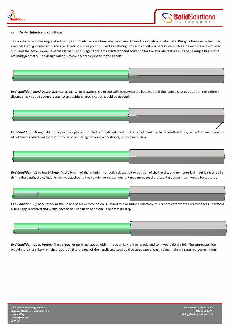
c) Design Intent- end conditions
The ability to capture design intent into your models can save time when you need to modify models at a later date. Design intent can be built into
sketches through dimensions and sketch relations (see point (d)) and also through the end conditions of features such as the extrude and extruded
cut. Take the below example of the ratchet. Each image represents a different end condition for the extrude feature and the bearing it has on the
resulting geometry. The design intent is to connect the cylinder to the handle:
End Condition: Blind Depth- 125mm- at the current status the extrude will merge with the handle, but if the handle changes position the 125mm
distance may not be adequate and so an additional modification would be needed.
End Condition: Through All- The cylinder depth is to the furthest right extremity of the handle and due to the drafted faces, two additional segments
of solid are created and therefore would need cutting away in an additional, unnecessary step.
End Condition: Up to Next/ Body- As the length of the cylinder is directly related to the position of the handle, and no numerical input is required to
define the depth, the cylinder is always attached to the handle, no matter where it may move to; therefore the design intent would be captured.
End Condition: Up to Surface- As the up to surface end condition is limited to one surface selection, this cannot cater for the drafted faces, therefore
a small gap is created and would have to be filled in an additional, unnecessary step
End Condition: Up to Vertex- The defined vertex is just about within the boundary of the handle and so it would do the job. The vertex position
would more than likely remain proportional to the rest of the handle and so should be adequate enough to maintain the required design intent.

Solid Solutions Management Ltd www.solidsolutions.co.uk Olympus House, Olympus Avenue 01926 333777 Europa Way [email protected] Leamington Spa CV34 6BF
d) Sketch Dimensions and Relations
2D sketches form the basis for the majority of model making features. It is important the sketches are constrained appropriately to capture the
required design intent. Sketches are classified into three states:
Fully Defined: The shape, size and location in respect to the origin have been sufficiently constrained using dimensions, relations or a combination of
both. All sketch lines and point will turn black.
Under Defined: There are still elements of the sketch that require constraints, to test, drag the blue sketch points and lines to uncover their degree
of freedom.
Over Defined: The sketch contains duplicate dimensions/ relations or conflicts that cannot both be solved. For example, two perpendicular lines do
not need a 90 degree angle specified between them. Also a pair of lines cannot be both parallel and perpendicular at
the same time.
The desired outcome for all sketches should be to get them into a fully defined status. The reason for this is that you
will then be in complete control of the sketches. The dimensions that are captured will become the only way in which
the sketch can be modified.
Sketch relations can add extra intelligence in comparison with dimensions, as they can avoid the need to have extra
dimensions. For example if you sketch two circles in the same sketch that are of equal diameters, rather than
dimensioning each one individually, you can dimension one, and make the second equal with a sketch relation. If the
size ever changes, the one dimension will then drive both circles.
The easiest way to capture sketch relations is to hold the CTRL key on your keyboard and select the two or more
entities you wish to relate together. When you have selected a valid group of lines, you will be offered relations on the
left hand side of the screen. SolidWorks will try to guess the most appropriate relation by highlighting the text in bold.
You can review existing sketch relations by selecting the “Display/Delete Relations” button on the
sketch toolbar. This tells you the relation type and then the entities it is related to.
Bear in mind that dimensions you apply in the sketch can come through into your Engineering
drawings, so dimension sketches in a way that will be appropriate for manufacturers. Take the example below. The
two sketches are identical apart from the way they have been dimensioned.
The left first sketch has explicitly defined the positions of the holes relative to the left and right hand edges of the
rectangular plate. This will ensure that any change to the 100mm width will keep the holes related appropriately. In
the second sketch, changing the 100mm width will either reduce or add material to the right hand side of the second
hole. Therefore capturing the correct dimension aides design intent and drawing creation.

Solid Solutions Management Ltd www.solidsolutions.co.uk Olympus House, Olympus Avenue 01926 333777 Europa Way [email protected] Leamington Spa CV34 6BF
e) Creating Reference Planes-
New in 2010
Reference planes are required for any 2 dimensional sketch, they have been substantially revamped for 2010
making them much more intuitive and allowing more than double the number of combinations.. The three standard
reference planes- Front, Top and Right are available to use by default but additional reference planes can also be
created. As well as sketches planes are used for a variety of other features such as: Cut with Surface, Split, Section
Views, and Mirror Pattern.
The ability to create additional reference planes gives the user full control over where sketches need to be
positioned. Planes are created with the command; Insert > Reference Geometry > Plane
Rather than the user being reliant on knowing the necessary selections, the user now simply picks the references
that they want to use in the creation of the planes and SolidWorks will automatically offer the necessary solutions.