multi-scale microstructural investigation of a laser 3d
TRANSCRIPT

Contents lists available at ScienceDirect
Additive Manufacturing
journal homepage: www.elsevier.com/locate/addma
Research Paper
Multi-scale microstructural investigation of a laser 3D printed Ni-basedsuperalloy
Yao Lia,b, Kai Chenb,*, R. Lakshmi Narayanc, Upadrasta Ramamurtyd, Yudong Wanga,Juncheng Longa, Nobumichi Tamurae, Xin Zhouf
a School of Materials Science and Engineering, Chang’an University, Xi’an, Shaanxi 710064, Chinab Center for Advancing Materials Performance from the Nanoscale (CAMP-Nano), State Key Laboratory for Mechanical Behavior of Materials, Xi’an Jiaotong University,Xi’an, Shaanxi 710049, Chinac Department of Materials Science and Engineering, Indian Institute of Technology, Delhi, New Delhi 110016, Indiad School of Mechanical and Aerospace Engineering, Nanyang Technological University, Singapore 639798, SingaporeeAdvanced Light Source, Lawrence Berkeley National Laboratory, Berkeley, CA 94720, USAf Science and Technology on Plasma Dynamics Laboratory, Air Force Engineering University, Xi’an, 710038, China
A R T I C L E I N F O
Keywords:Directed energy depositionMulti-scale microstructuresCellular structuresNon-uniform dislocation distributionNi-based superalloys
A B S T R A C T
The heterogeneous microstructure of a laser 3D printed Ni-based superalloy was examined at multiple lengthscales. The sub-millimeter-sized columnar crystal grains are composed of micron-sized cellular colonies. Thecrystal grains grow in epitaxy with the substrate under the large temperature gradient and high cooling rate. Thecell boundaries, decorated with γ/γ′ eutectics, μ-phase precipitates and high density of dislocations, show en-richment of γ′ forming elements and low-angle misorientations. Dislocations trapped in the intra-cellular regionsare characterized as statistically stored dislocations with no detectable contribution to lattice curvature, and arethe results of the interaction between dislocations and γ′ precipitates.
1. Introduction
Laser additive manufacturing, which is commonly referred to aslaser 3D printing (L3DP), has great potential for near net shape man-ufacturing as well as repair of gas turbine engine components composedof single crystal or directionally solidified Ni-based superalloys withhigh γ′ content (> 60 %) [1]. Based on the powder feeding strategy,L3DP can be categorized into either direct energy deposition (DED) orpowder bed fusion (PBF). Due to the focused heat source and reducedheat input, a steep temperature gradient, parallel to the building di-rection, is present during both the DED and PBF processes, facilitatingepitaxial crystal growth with the base plate metal orientation. Si-multaneously, heterogeneous microstructures with length scales ran-ging from nanometer to sub-millimeter are generated from the rapidsolidification of the DED and PBF process [2–5]. These are otherwisenot feasible through conventional methods of manufacturing. The highcooling rates inherent to L3DP severely suppress the growth of sec-ondary dendrite arms, making it challenging to distinguish betweencells and dendrites [6] in the absence of crystal orientation knowledge.Hence, the term “cell” is generally used to denote the cellular/dendriticstructures in 3D printed alloys. The fine cellular structures,
accompanied by both elemental and dislocation partitioning, have beenreported in a variety of 3D printed face-centered cubic alloys, includingAl alloys [7], austenite stainless steels [2,8,9], high-entropy alloys [10]and Ni-based superalloys [11–14].
The simultaneous enhancements in strength and ductility of 3Dprinted alloys, compared to their conventionally manufactured coun-terparts, are attributed to such cellular structures [2,8]. There is how-ever no consensus on the exact mechanism leading to the observedstrengthening. In the absence of detailed characterization of the mis-orientations across them, the cell boundaries are treated as conven-tional high-angle grain boundaries (HAGBs), leading to a Hall-Petchrelation based description of strength [2]. Some authors however arguethat cell boundaries cannot be regarded as HAGBs, and attribute theobserved strengthening to dislocation interactions (work hardening)together with elemental segregation (solid solution strengthening) andcrystal grain refinement (if any) [10,15]. In this context, it is worthnoting that most of such observations and discussions are based onaustenite stainless steels, high entropy alloys and Ni-based superalloyswith low γ′ content (e.g. IN718 and IN625) [13,16]. However, only afew studies have been reported in laser 3D printed directionally soli-dified and single crystalline Ni-based superalloys with high Ti/Al
https://doi.org/10.1016/j.addma.2020.101220Received 12 January 2020; Received in revised form 28 March 2020; Accepted 1 April 2020
⁎ Corresponding author.E-mail address: [email protected] (K. Chen).
Additive Manufacturing 34 (2020) 101220
Available online 25 April 20202214-8604/ © 2020 Elsevier B.V. All rights reserved.
T

contents and thus high γ′ volume fraction, especially without postprocessing heat treatment [11,17]. In particular, detailed knowledge ofthe dislocation type and distribution, and how the chemical in-homogeneity associated with the cellular structure influences the size,morphology, and phase of the strengthening precipitates is essential tounderstand the mechanical performance of 3D printed Ni-based su-peralloys. Keeping this in view, we report here the results of a com-prehensive microstructural study on a Ni-based superalloy manu-factured by DED technique.
2. Materials and methods
Gas atomized DD4 superalloy powders with a diameter range of40–120 μm were used as the feedstock for the DED process. An in-housedeveloped co-axial laser cladding apparatus was employed and a 7 mmdiameter 15 mm long cylinder was deposited on the (001) surface of adirectionally solidified Ni-based superalloy DZ125L substrate using ascan protocol where the scanning direction of each layer was perpen-dicular to the previous one. The nominal compositions of DD4 powdersand DZ125L substrate are listed in Table 1. The DED process was car-ried out with a fixed laser power of 230 W and a scan rate of 10 mm/sunder an Ar protective atmosphere. Powders carried by Ar gas were
injected into the melt pool at a rate of ∼9 mm3/s. More detailed in-formation about the manufacturing process can be found elsewhere[18].
After the DED process, the specimens were cut from the cylinders.After mechanical polishing and electrical etching in an aqueous solu-tion consisting of 30 vol% H3PO4, microstructural investigation wascarried out under an optical microscope (OM, Carl Zeiss Axio Scope A1)and a scanning electron microscope (SEM, Hitachi SU6600) equippedwith energy dispersive spectroscopy (EDS). Electron backscattereddiffraction (EBSD) equipped in a focused ion beam system (FIB, FEIHelios 600 NanoLab DualBeam) was conducted for the study of grainstructures. An EBSD measurement from the cross-sectional area up to1350 × 1150 μm2 was acquired with 5 μm step size and post-processedby MTEX toolbox [19]. Synchrotron X-ray microdiffraction (μXRD) wasconducted on beamline 12.3.2 at the Advanced Light Source of theLawrence Berkeley National Laboratory. The cross-sectional specimenwas mounted on the sample stage at a 45° incline angle relative to thepolychromatic X-ray beam (5–24 keV). 3600 Laue Patterns (LP) werecollected using a two-dimensional X-ray detector (DECTRIS Pilatus 1M)over an area of 60 × 60 μm2 with 1 μm step size and 0.5 s exposuretime at each scan position, and subsequently indexed by using thecustom-developed software package XMAS for mapping the orientation
Table 1Nominal compositions of the substrate and powders.
Composition (wt%) C Cr Co Mo W Al Ti Ta Ni
DZ125L substrate 0.12 8.74 9.54 2.21 6.46 5.03 3.18 3.96 BalanceDD4 powders 0.004 8.97 7.26 1.94 6.91 3.94 4.22 3.73 Balance
Fig. 1. The cellular microstructures in the DEDed superalloy. OM images collected from the (a) longitudinal section and (b) cross-sectional specimens. Theyellow arrows in (a) and (b) denote the fusion lines. (c) An enlarged view of (b) showing the typical cell morphology. (d) BSE SEM image showing the dispersedprecipitates along the cell boundaries from the cross-sectional view.
Y. Li, et al. Additive Manufacturing 34 (2020) 101220
2

deviations. Full details of the μXRD setup and LP indexing process canbe found in Ref. [20,21]. The EBSD and μXRD specimens were fabri-cated by electrical polishing in a solution of 92 % alcohol and 8%perchloric acid at 25 V. In addition, the cross-sectional specimen wasthinned with a twin-jet electro-polishing machine, and investigatedunder transmission electron microscope (TEM, 200 kV JOEL 2100F) toexamine the microstructures at the nano-scale.
3. Results
Low magnification optical micrograph (Fig. 1a) of the longitudinalsection of the specimen, shows the substrate/cladding layer interfaceand the layer-by-layer deposition patterns outlined by the fusion lines,which are also visible from the cross-sectional view in Fig. 1b. Thethickness of each deposited layer was measured to be about 100 μm.The observation of grain boundaries (GBs), one of which is marked withwhite arrows in Fig. 1a, running across multiple deposited layers fromsubstrate, implies epitaxial growth of the columnar grains. In eachgrain, columnar cells orient preferentially parallel to the building di-rection. From the cross-sectional view in Fig. 1c, these cell coloniesappear equiaxed in the direction transverse to the building direction.The cells can therefore be viewed as long cylindrical rods with anaverage diameter of ∼6 μm. Under the backscattered electron (BSE)mode of SEM, the cells are outlined by the high density of nano-sizedparticles with bright contrast at the boundaries (Fig. 1d). These regionsare enriched in Cr, Mo, Ta, Ti and W, as revealed in the energy dis-persive spectroscopy (EDS) maps (Fig. 2).
From the SEM image (Fig. 3a) and dark field TEM image (Fig. 3b)illuminated by the 100 reflection of γ′ precipitates (Fig. 3c), two dif-ferent morphologies of γ′ precipitates are observed. In the intra-cellularregions, small, close-packed and neatly ordered near-cuboidal γ′ pre-cipitates with an average size of ∼30 nm can be seen. Along the cellboundaries, however, rectangular γ/γ′ eutectic phases, with a typical γ′
size of ∼80 nm (width) ×200 nm (length), aggregate in a comb-likemorphology. Moreover, a topologically closed-packed (TCP) particlenear the γ/γ′ eutectic was identified as the μ-phase with rhombohedralcrystal structure, as evidenced from the corresponding selected areaelectron diffraction (SAED) study in Fig. 3d.
From the out-of-plane inverse pole figure (IPF-Z) map obtainedusing EBSD in Fig. 4a, a broad grain size distribution is observed andthe largest grain is close to 1 mm in diameter. Most of the grains in redreveal that their [001] directions are almost parallel to the buildingdirection. Since the aim of the present study is to surrogate the repair ofa turbine blade tip, the substrate surface normal is also along the [001]direction. Thus the deposited layers are epitaxial with the substrate.The uneven colors in the grain interior indicate the presence of in-tragranular orientation gradients, and the low angle grain boundaries(LAGBs) visible in the kernel average misorientation (KAM) map(Fig. 4b) confirm the existence of a sub-grain structure. It should benoted that the value of the extent of orientation variance betweencellular colonies is barely accessible by conventional EBSD method [2]due to its poor angular resolution (∼0.5°). Therefore, synchrotronμXRD technique with superior orientation resolution (< 0.01°) wasemployed [22].
As seen in the IPF-Z map of the synchrotron μXRD study (Fig. 4c),the whole scanned area has a similar orientation, yet an isolated sub-grain domain, in orange, deviates ∼12° relatively to its surroundings.Since the sub-grain orientation variation is hardly discernable from theIPF-Z map, the misorientation angle of each scan spot relative to theaverage orientation of the whole scan is calculated and shown inFig. 4d. The map shows the whole scan area is composed of a multitudeof cellular colonies in distinctive colors. This suggests that the growthdirection of each cell is slightly misaligned, while the orientation withineach single cell is nearly identical. Consequently, LAGBs observed fromthe KAM map (Fig. 4e) delineate the cell boundaries and hence outlinethe size/shape of cell colonies, in agreement with the optical
Fig. 2. EDS element distributions collected from the cross-sectional specimen.
Y. Li, et al. Additive Manufacturing 34 (2020) 101220
3

microscopy and SEM images displayed in Fig. 1c and d. As seen inFig. 4f, ten cells can be clearly distinguished from the nine peaks alongthe misorientation profile obtained through the blue horizontal line inFig. 4e. The misorientation angle between each pair of adjacent cellsranges from 1° to 4°, while the low amplitude orientation variations(< 0.1°) in the intra-cellular scale are negligible.
In general, LAGBs are formed as dislocations arrange into en-ergetically favorable configurations and are necessary for the accom-modation of lattice curvatures [23]. To verify this, we examined thedislocation structure in the cross-sectional specimen using TEM inscanning transmission electron microscopy (STEM) mode. As seen inFig. 5a, the cell boundaries, in dark contrast and denoted by hollowarrows, are decorated with γ/γ′ eutectics and irregular shaped μ par-ticles with average size of about 200 nm. An enlarged view displayed inFig. 5b suggests large populations of dislocations tangling along the cellboundary. Since these dislocations are not homogeneously distributed,possibly because their mobility is impeded by μ particles, LAGBs, andcoarse γ′ precipitates of γ/γ′ eutectics, it is difficult to estimate theirdensity quantitatively. In the interior of the cells, however, the dis-location lines are distributed more homogeneously (Fig. 5c). Using theline-intercept method adopted by Norfleet et al. [24], the dislocation
density in the cell interior is estimated to be ∼1.4 × 10¹⁴ m−2.
4. Discussion
From the multi-scale characterization approach described above,the heterogeneous microstructure of the 3D printed superalloy, sche-matically displayed in Fig. 6, can be constructed. Although the crystalgrains obtained in 3D printed superalloys are usually coarse (grain sizeof up to hundreds of microns or even at a centimeter scale for a singlecrystal [25]), they are composed of submicron to micron sized cellularstructures, exhibiting elemental segregation, inhomogeneous distribu-tions of dislocations and precipitates, and small misorientation betweenadjacent cells. The cell boundaries are enriched in γ′ forming elements,resulting in larger γ′ precipitates in the inter-cellular regions than in thecell interiors [26]. In some of the superalloys like the one studied here,particles with TCP phases are detected [27]. High and non-uniformdensity of tangled dislocations are observed along the cell boundaries.Dislocations also exist in the cell interior; although their density islower than those along the cell boundaries, it is higher than those in thecell interiors of 3D printed stainless steels [2,8] and high entropy alloys[10]. Typically, the rapid cooling rate and the repeated heating/cooling
Fig. 3. The phase distribution in the DEDed superalloy. The combination of (a) BSE SEM and (b) TEM dark field images reveals two types of γ′ morphologies.SEAD patterns evidence (c) the coherent γ/γ′ microstructure and (d) the μ-phase precipitates.
Y. Li, et al. Additive Manufacturing 34 (2020) 101220
4
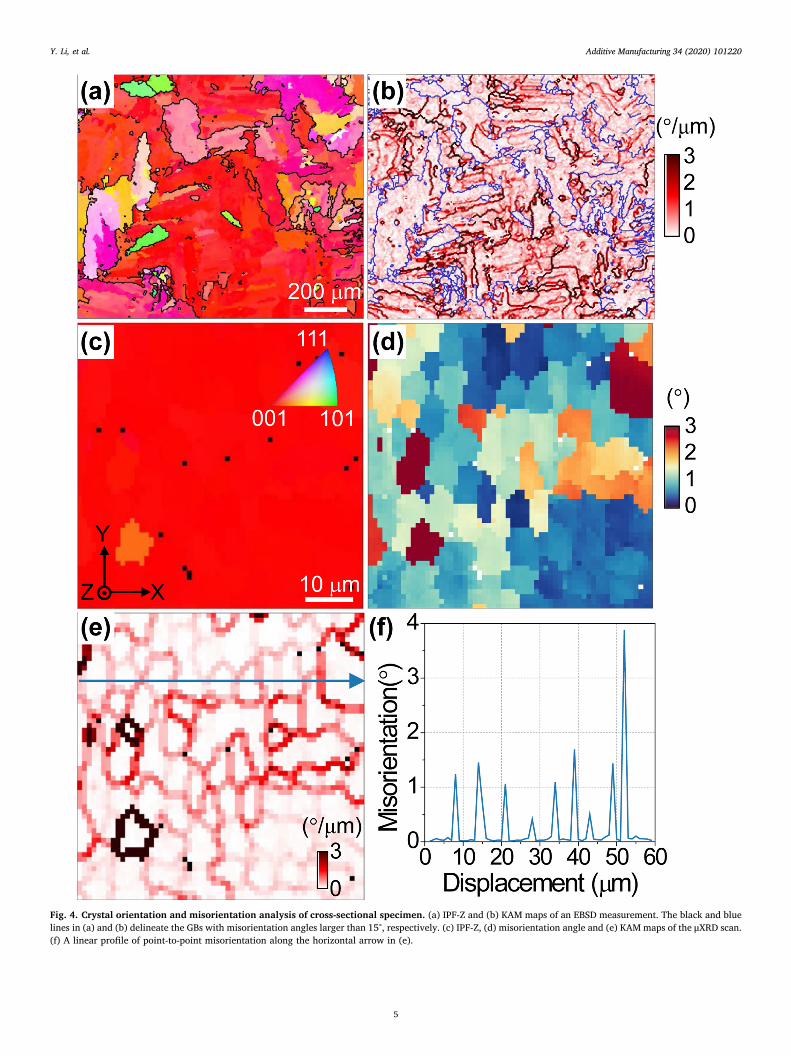
Fig. 4. Crystal orientation and misorientation analysis of cross-sectional specimen. (a) IPF-Z and (b) KAM maps of an EBSD measurement. The black and bluelines in (a) and (b) delineate the GBs with misorientation angles larger than 15°, respectively. (c) IPF-Z, (d) misorientation angle and (e) KAM maps of the μXRD scan.(f) A linear profile of point-to-point misorientation along the horizontal arrow in (e).
Y. Li, et al. Additive Manufacturing 34 (2020) 101220
5

cycles generated by the motion of the laser beam induce intensethermal stresses that can exceed the yield strength of the claddingmaterials [18]. Additionally, for γ′-strengthened Ni-based superalloy,the rapid precipitation of γ′ will also introduce pronounced phasetransition stresses due to the γ/γ′misfit. The superimposition of thermalstresses and phase transition stresses induce a large number of dis-locations both in the cell center and in the intercellular region. A pos-sible reason for the distinguished intra-cellular dislocation distributionof superalloys studied here from the 3D printed stainless steels and highentropy alloys is the strong hindrance to dislocation mobility caused bythe γ′ particles.
The cellular microstructure is due to the rapid solidification processduring 3D printing. According to the undercooling criterion [28], so-lidification microstructure depends on temperature gradient (G), soli-dification rate (R), and undercooling temperature (ΔT) of the melt pool.Cellular solidification prevails if G/R> ΔT/D, where D is the diffusioncoefficient. In L3DP, G usually reaches 105∼107 K/m [29], which is atleast 3 orders of magnitude higher than the temperature gradient intraditional casting conditions. As the cooling rate, i.e. the multiplicationof G and R, is inversely proportional to the cell spacing (or primarydendrite arm spacing), the observed cell spacing (∼6 μm) is larger thanmost of other reported superalloys fabricated by PBF (< 1 μm) [11,12],suggesting that R is relatively low in the present study, although still 2orders of magnitude higher than that for conventional casting condi-tions [29]. The resulting large G/R ratio facilitates the formation of
cellular structures. It is also suggested that a high G gives rise to strongthermo-capillary convection due to the surface-tension driven in-stability, or Benard-Marangoni surface instability [30], which promotesthe ejected γ′ forming elements to accumulate in the inter-cellular li-quid, and, in turn, triggers the eutectic reaction L → γ + γ′ in the finalstage of solidification [26,31]. Since the γ′ solvus rises with increasingcontent of γ′ forming elements, inter-cellular γ′ particles precipitate at ahigher temperature and experience longer period over which they cancoarsen [26]. Since superalloys with high W or/and Mo content show astrong tendency for μ-phase formation during conventional solidifica-tion, the μ-phase observed in this study is believed to nucleate directlyfrom the inter-cellular liquid, i.e. primary μ-phase [32]. Moreover, asshown in Fig. S1 in the Supplementary Material, the lamellar featuresobserved within the TCP particle imply the presence of growth faults,which may have been introduced by the thermal stresses that ariseduring the 3D printing process [32].
As for the layer-by-layer deposition process, partial remelting of theunderlying layers is necessary for a strong metallographic bond be-tween two adjacent deposit layers. Simultaneously, the unmolten layersalso serve as the substrate for the epitaxial growth of the newly formedcells. However, affected by the flowing field, cell growth deflects to-ward upper stream and the deflection angles varies at different loca-tions in the melt pool [33], leading to a slight orientation variationbetween different cells. On the other hand, although the solidificationcell growth front aligns along the favored [001] crystallographic
Fig. 5. STEM TEM analysis of dislocation configurations at the cellular scale. (a) A full view of a cell colony and dislocation configurations, (b) near the cellboundary, and (c) in the cell interior.
Fig. 6. Schematic illustration of the microstructures from the sub-millimeter to nanometer scales in the cross-sectional view of DEDed Ni-based superalloy.
Y. Li, et al. Additive Manufacturing 34 (2020) 101220
6

direction, which is anti-parallel to the heat flux, the individual cells,regarded as cantilever beams, are anchored at the position of the so-lidus isotherm once the inter-cellular liquid starts to freeze and issubjected to bending moments and torques caused by thermal stresses[34]. Therefore, the accumulated misorientation is an outcome of thelayer-by-layer building process. Because of the complex solidificationprocess and the presence of plastic stresses, dislocations are also formedin the deformable γ channels and bow out between hard γ′ precipitates.In addition, the complex solidification paths, including melting, partialre-melting, cyclic annealing, γ′ dissolution and re-precipitation, lead tothe inhomogeneous distribution of γ′ precipitates, resulting in compli-cated interactions between the dislocations and the γ′ precipitates. Thusthe dislocations are distributed in the cells with random signs [35]. Inother words, these dislocations are statistically stored dislocations(SSDs). This is why the lattice curvature is not observed in the intra-cellular regions using the μXRD technique.
5. Conclusions
In summary, heterogeneous microstructures, including fusion lines,columnar grains, LAGBs as well as the elemental distribution, phaseconstituents and dislocation configurations at the cellular scale are in-vestigated in a DEDed superalloy. The epitaxial growth of cells andcolumnar grains are attributed to the partial remelting of underlyingdeposit layers and the maximum heat flow antiparallel to the buildingdirection. Cell boundaries, identified as LAGBs, are decorated with γ/γ′eutectics, μ-phases and non-uniform dislocation arrangements, whichare linked to the inter-cellular segregation of γ′ forming elementsduring the DED process. In contrast to the cell structures in other 3Dprinted alloys with small to negligible volume fraction of strengtheningprecipitates, intra-cellular dislocation density in the γ′-strengthenedsuperalloys is significantly higher but do not contribute to lattice cur-vature, and is attributed to the interactions between dislocations and γ′precipitates leading to the formation of SSDs.
Declaration of Competing Interests
The authors declare that they have no known competing financialinterests or personal relationships that could have appeared to influ-ence the work reported in this paper.
CRediT authorship contribution statement
Yao Li: Investigation, Formal analysis, Writing - original draft. KaiChen: Conceptualization, Writing - original draft, Supervision. R.Lakshmi Narayan: Writing - review & editing. UpadrastaRamamurty: Writing - review & editing. Yudong Wang: Visualization.Juncheng Long: Visualization. Nobumichi Tamura: Formal analysis,Data curation, Writing - review & editing. Xin Zhou: Resources.
Acknowledgements
We thank Mr. S.C. Lin for valuable discussions, Dr. Y.B. Qin and Ms.D.L. Zhang for TEM operation and data analyses. This work is supportedby National Natural Science Foundation of China (Grant No. 51901026,91860109, 51671154, 51927801) and the National Key Research andDevelopment Program of China (Grant No. 2016YFB0700404). Y. L.acknowledges the support from the Fundamental Research Funds forthe Central Universities (CHD No. 300102319301). The ALS is sup-ported by the Director, Office of Science, Office of Basic EnergySciences, Materials Science Division, of the U.S. Department of Energyunder Contract No. DE-AC02-05CH11231 at LBNL.
Appendix A. Supplementary data
Supplementary material related to this article can be found, in the
online version, at doi:https://doi.org/10.1016/j.addma.2020.101220.
References
[1] R. Vilar, A. Almeida, Repair and manufacturing of single crystal Ni-based super-alloys components by laser powder deposition—a review, J. Laser Appl. 27 (2015)S17004.
[2] Y.M. Wang, T. Voisin, J.T. McKeown, J. Ye, N.P. Calta, Z. Li, Z. Zeng, Y. Zhang,W. Chen, T.T. Roehling, R.T. Ott, M.K. Santala, P.J. Depond, M.J. Matthews,A.V. Hamza, T. Zhu, Additively manufactured hierarchical stainless steels with highstrength and ductility, Nat. Mater. 17 (2018) 63–70.
[3] A. Basak, R. Acharya, S. Das, Epitaxial deposition of nickel-based superalloy René142 through scanning laser epitaxy (SLE), Addit. Manuf. 22 (2018) 665–671.
[4] P. Kumar, O. Prakash, U. Ramamurty, Micro-and meso-structures and their influ-ence on mechanical properties of selectively laser melted Ti-6Al-4V, Acta Mater.154 (2018) 246–260.
[5] P. Kumar, U. Ramamurty, Microstructural optimization through heat treatment forenhancing the fracture toughness and fatigue crack growth resistance of selectivelaser melted Ti–6Al–4V alloy, Acta Mater. 169 (2019) 45–59.
[6] T.T. Roehling, S.S.Q. Wu, S.A. Khairallah, J.D. Roehling, S.S. Soezeri, M.F. Crumb,M.J. Matthews, Modulating laser intensity profile ellipticity for microstructuralcontrol during metal additive manufacturing, Acta Mater. 128 (2017) 197–206.
[7] B. Chen, S.K. Moon, X. Yao, G. Bi, J. Shen, J. Umeda, K. Kondoh, Strength and strainhardening of a selective laser melted AlSi10Mg alloy, Scr. Mater. 141 (2017) 45–49.
[8] L. Liu, Q. Ding, Y. Zhong, J. Zou, J. Wu, Y.L. Chiu, J. Li, Z. Zhang, Q. Yu, Z. Shen,Dislocation network in additive manufactured steel breaks strength–ductility trade-off, Mater. Today. 21 (2018) 354–361.
[9] J. Suryawanshi, K.G. Prashanth, U. Ramamurty, Tensile, fracture, and fatigue crackgrowth properties of a 3D printed maraging steel through selective laser melting, J.Alloys Compd. 725 (2017) 355–364.
[10] Z.G. Zhu, X.H. An, W.J. Lu, Z.M. Li, F.L. Ng, X.Z. Liao, U. Ramamurty, S.M.L. Nai,J. Wei, Selective laser melting enabling the hierarchically heterogeneous micro-structure and excellent mechanical properties in an interstitial solute strengthenedhigh entropy alloy, Mater. Res. Lett. 7 (2019) 453–459.
[11] X. Wang, L.N. Carter, B. Pang, M.M. Attallah, M.H. Loretto, Microstructure andyield strength of SLM-fabricated CM247LC Ni-superalloy, Acta Mater. 128 (2017)87–95.
[12] M. Ni, S. Liu, C. Chen, R. Li, X. Zhang, K. Zhou, Effect of heat treatment on themicrostructural evolution of a precipitation-hardened superalloy produced by se-lective laser melting, Mater. Sci. Eng. A 748 (2019) 275–285.
[13] M. Pröbstle, S. Neumeier, J. Hopfenmüller, L.P. Freund, T. Niendorf, D. Schwarze,M. Göken, Superior creep strength of a nickel-based superalloy produced by se-lective laser melting, Mater. Sci. Eng. A 674 (2016) 299–307.
[14] S. Sui, J. Chen, R. Zhang, X. Ming, F. Liu, X. Lin, The tensile deformation behavior oflaser repaired Inconel 718 with a non-uniform microstructure, Mater. Sci. Eng. A688 (2017) 480–487.
[15] Z. Li, B. He, Q. Guo, Strengthening and hardening mechanisms of additively man-ufactured stainless steels: the role of cell sizes, Scr. Mater. 177 (2020) 17–21.
[16] G.P. Dinda, A.K. Dasgupta, J. Mazumder, Laser aided direct metal deposition ofInconel 625 superalloy: microstructural evolution and thermal stability, Mater. Sci.Eng. A 509 (2009) 98–104.
[17] K. Chen, R. Huang, Y. Li, S. Lin, W. Zhu, N. Tamura, J. Li, Z.-W. Shan, E. Ma,Rafting-enabled recovery avoids recrystallization in 3D-printing-repaired single-crystal superalloys, Adv. Mater. (2020) 1907064.
[18] Y. Li, D. Qian, J. Xue, J. Wan, A. Zhang, N. Tamura, Z. Song, K. Chen, A synchrotronstudy of defect and strain inhomogeneity in laser-assisted three-dimensionally-printed Ni-based superalloy, Appl. Phys. Lett. 107 (2015) 181902.
[19] R. Hielscher, H. Schaeben, A novel pole figure inversion method: specification ofthe MTEX algorithm, J. Appl. Cryst. 41 (2008) 1024–1037.
[20] N. Tamura, XMAS: a versatile tool for analyzing synchrotron X-ray microdiffractiondata, in: R. Barabash, G. Ice (Eds.), Strain Dislocation Gradients from Diffr. Spat.Local Struct. Defects, World Scientific, London, 2014, pp. 125–155.
[21] J. Kou, K. Chen, N. Tamura, A peak position comparison method for high-speedquantitative Laue microdiffraction data processing, Scr. Mater. 143 (2018) 49–53.
[22] G. Zhou, J. Kou, Y. Li, W. Zhu, K. Chen, N. Tamura, Quantitative scanning Lauediffraction microscopy: application to the study of 3D printed nickel-based super-alloys, Quantum Beam Sci. 2 (2018) 13.
[23] O. Muránsky, L. Balogh, M. Tran, C.J. Hamelin, J.S. Park, M.R. Daymond, On themeasurement of dislocations and dislocation substructures using EBSD and HRSDtechniques, Acta Mater. 175 (2019) 297–313.
[24] D.M. Norfleet, D.M. Dimiduk, S.J. Polasik, M.D. Uchic, M.J. Mills, Dislocationstructures and their relationship to strength in deformed nickel microcrystals, ActaMater. 56 (2008) 2988–3001.
[25] E. Chauvet, C. Tassin, J.J. Blandin, R. Dendievel, G. Martin, Producing Ni-basesuperalloys single crystal by selective electron beam melting, Scr. Mater. 152(2018) 15–19.
[26] Y. Li, K. Chen, N. Tamura, Mechanism of heat affected zone cracking in Ni-basedsuperalloy DZ125L fabricated by laser 3D printing technique, Mater. Des. 150(2018) 171–181.
[27] H. Xiao, S. Li, X. Han, J. Mazumder, L. Song, Laves phase control of Inconel 718alloy using quasi-continuous-wave laser additive manufacturing, Mater. Des. 122(2017) 330–339.
[28] S. Kou, Welding Metallurgy, New Jersey, USA (2003), pp. 431–446.[29] M. Gäumann, S. Henry, F. Cléton, J.-D. Wagnière, W. Kurz, Epitaxial laser metal
forming: analysis of microstructure formation, Mater. Sci. Eng. A 271 (1999)
Y. Li, et al. Additive Manufacturing 34 (2020) 101220
7

232–241.[30] K.G. Prashanth, J. Eckert, Formation of metastable cellular microstructures in se-
lective laser melted alloys, J. Alloys Compd. 707 (2017) 27–34.[31] Y.-J. Liang, J. Li, A. Li, X.-T. Pang, H.-M. Wang, Solidification path of single-crystal
nickel-base superalloys with minor carbon additions under laser rapid directionalsolidification conditions, Scr. Mater. 127 (2017) 58–62.
[32] K. Zhao, Y.H. Ma, L.H. Lou, Z.Q. Hu, μ phase in a nickel base directionally solidifiedalloy, Mater. Trans. 46 (2005) 54–58.
[33] G. Wang, J. Liang, Y. Zhou, L. Zhao, T. Jin, X. Sun, Variation of crystal orientationduring epitaxial growth of dendrites by laser deposition, J. Mater. Sci. Technol. 34(2018) 732–735.
[34] J.W. Aveson, P.A. Tennant, B.J. Foss, B.A. Shollock, H.J. Stone, N. D’Souza, On theorigin of sliver defects in single crystal investment castings, Acta Mater. 61 (2013)5162–5171.
[35] T. Tinga, W.A.M. Brekelmans, M.G.D. Geers, Cube slip and non-Schmid effects insingle crystal Ni-base superalloys, Model. Simul. Mater. Sci. Eng. 18 (2010).
Y. Li, et al. Additive Manufacturing 34 (2020) 101220
8