a study of microstructural fatigue and residual stress ... study of microstructural fatigue and...
TRANSCRIPT
A study of microstructural fatigue and residual stress evolution in titanium plates deformed by mechanical and laser bending
H. Fidder1, A. Els-Botes2, S. Woudberg3, P. J. McGrath4, V. Ocelik & J. Th. M. de Hosson 5 51Department of Mechanical Engineering, Cape Peninsula University of Technology, South Africa 2CSIR – National Laser Centre, South Africa 3Applied Mathematics Division, Department of Mathematical Sciences, Stellenbosch University, South Africa 4 Department of Mechanical Engineering, Nelson Mandela Metropolitan University, South Africa 5Department of Applied Physics, Zernike Institute for Advanced Material, University of Groningen, Netherlands
Abstract
This manuscript details the investigation of residual stresses and microstructural changes in commercially pure titanium plates deformed by three bending methods, i.e. (i) mechanically, (ii) using a laser beam and (iii) by a combination of laser and mechanical bending to a final radius of curvature of 120 mm. The residual strains were measured using the hole-drilling method and the analyses indicate that higher tensile residual stresses reside in the laser bent plate samples compared to that assessed from the other two bending methods. However, an important finding was that the residual stress state of laser bent samples was significantly reduced after application of mechanical bending for samples subjected to the combined bending application. This aspect coupled with the increased hardness due to microstructural changes makes the laser/mechanical bending process more favourable when designing against fatigue failure. Keywords: residual stress, fatigue, laser forming, mechanical forming, commercially pure (CP) titanium.
WIT Transactions on Engineering Sciences, Vol 91, www.witpress.com, ISSN 1743-3533 (on-line)
© 2015 WIT Press
doi:10.2495/SECM150031
Surface and Contact Mechanics including Tribology XII 23
1 Introduction
Titanium and titanium alloys are used extensively in many industrial fields due to their good strength-to-weight ratio, corrosion resistance and high strength at elevated temperatures. These material characteristics are highly desirable in many applications, particularly in the aerospace industry. One of the more common manufacturing processes to fabricate curved sheet parts is the use of a three-point roller bending machine. However, laser forming which is a relatively new technique (e.g. Els-Botes et al. [1]; Els-Botes et al. [2], Fidder et al. [3]) allows the modification of shape (curvature) of sheet metal and is thus considered an advanced manufacturing process. The stress state of the deformed titanium plates is of particular research interest since the presence of residual stresses play an important role in quantifying the integrity and durability of components produced by the laser process (McGrath and Hughes [4]). The current study is aimed at evaluating the residual stresses in commercially pure (CP) titanium plates bent by the three different methods mentioned above. The residual stresses were determined using the hole-drilling technique according to the average stress method (ASM) and integral (IM) as described by the following references ASTM E837-08e1 [5]; Lu [6]; Maher et al. [7]; and Schajer [8, 9]. To the knowledge of the authors, no published information on the effects of the combined laser/mechanical bending process is available and no work has been published on the characterisation of the residual stress state and resultant microstructural changes. The objective of this study is to compare the effect of mechanical bending, laser bending and laser/mechanical bending on CP pure titanium plates with respect to hardness, fatigue, residual stress and microstructure.
2 Experimental procedure
2.1 Materials and bending processes
The material used in this study was CP ASME SB 265-6, grade 2 supplied as annealed 3 mm thick plate. The parent material had an average tensile strength of 430 MPa and yield strength of 380 MPa. Rectangular test samples (200 x 50 x 3 mm) were laser cut from the sheet and subsequently bent by three methods, namely: (i) laser bending (LB); (ii) mechanical bending (MB); and (iii) combined laser/mechanical bending (LB/MB). A 5 kW CW CO2 Trumpf laser was used to manufacture plate samples to curvatures of 120 mm for the LB process and to 240 mm for the LB/MB application. The laser parameters are shown in table 1 and the laser ‘line-heating’ (irradiation) sequence was such that there was a 50% overlap between consecutive ‘line-heating’ paths, that is, the defocused beam spot size of 12 mm resulted in an interval step of 6 mm. For the laser bending process three figplate samples were positioned and aligned adjacent to one another having a gap of approximately 2 mm between them. The multi-scan ‘line-heating’ process commenced 31 mm from either end, alternating between ends according to the interval step indicated, with the final scanned
WIT Transactions on Engineering Sciences, Vol 91, www.witpress.com, ISSN 1743-3533 (on-line)
© 2015 WIT Press
24 Surface and Contact Mechanics including Tribology XII
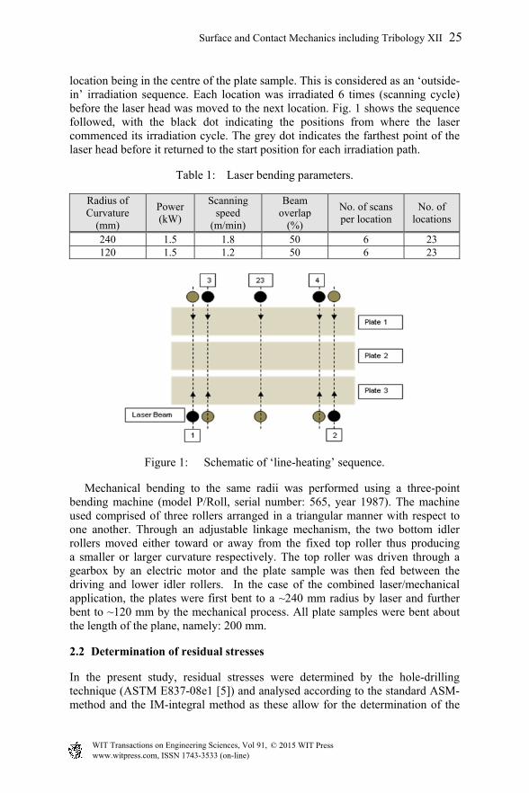
location being in the centre of the plate sample. This is considered as an ‘outside-in’ irradiation sequence. Each location was irradiated 6 times (scanning cycle) before the laser head was moved to the next location. Fig. 1 shows the sequence followed, with the black dot indicating the positions from where the laser commenced its irradiation cycle. The grey dot indicates the farthest point of the laser head before it returned to the start position for each irradiation path.
Table 1: Laser bending parameters.
Radius of Curvature
(mm)
Power (kW)
Scanning speed
(m/min)
Beam overlap
(%)
No. of scans per location
No. of locations
240 1.5 1.8 50 6 23 120 1.5 1.2 50 6 23
Figure 1: Schematic of ‘line-heating’ sequence.
Mechanical bending to the same radii was performed using a three-point bending machine (model P/Roll, serial number: 565, year 1987). The machine used comprised of three rollers arranged in a triangular manner with respect to one another. Through an adjustable linkage mechanism, the two bottom idler rollers moved either toward or away from the fixed top roller thus producing a smaller or larger curvature respectively. The top roller was driven through a gearbox by an electric motor and the plate sample was then fed between the driving and lower idler rollers. In the case of the combined laser/mechanical application, the plates were first bent to a ~240 mm radius by laser and further bent to ~120 mm by the mechanical process. All plate samples were bent about the length of the plane, namely: 200 mm.
2.2 Determination of residual stresses
In the present study, residual stresses were determined by the hole-drilling technique (ASTM E837-08e1 [5]) and analysed according to the standard ASM-method and the IM-integral method as these allow for the determination of the
WIT Transactions on Engineering Sciences, Vol 91, www.witpress.com, ISSN 1743-3533 (on-line)
© 2015 WIT Press
Surface and Contact Mechanics including Tribology XII 25
‘bulk relief stress’ and ‘stress with depth’, respectively. Both methods are important when designing against fatigue as the stresses assessed by the IM are considered to be associated with crack initiation whilst those analysed by the ASM are used for total life predictions. Micro-measurement type EA-06-062RE-120 rosettes were used for measuring the strain relaxation values. The rosettes were bonded to the mid-position of the curved surface, namely: middle of length and in the centre of the width plane. All samples evaluated for this study were analysed in similar locations. A total of eleven samples were analysed, one in the ‘as-received’ condition and two from each bending application, namely: four samples bent to the 240 mm curvature (two from each LB and MB applications) and six samples from the 120 mm curvature (two from each LB, MB and LB/MB applications). Of those analysed, one assessment was conducted on the outer curved surface and the second on the inner curved surface. For measurement consistency, the reference gauge of the rosette was aligned parallel to the longitudinal axis of the plate samples. Residual stresses were calculated from the measured strains using the following equation:
BA 4
24
,2
2132
1313minmax
(1)
In eqn. (1) σmax and σmin are the calculated relieved maximum and minimum stresses, respectively; 1 , 2 and 3 are the measured relieved strains; and A and B are calibration constants. The SINT system (model: RESTAN, Serial number: 012, year: 1997) was used for the hole drilling application. This system makes use of an inverted end mill and a high speed air turbine that is automatically controlled. Incremental cutting intervals of 0.1 mm with a delay time of 10 seconds (between the cutting intervals) were used to produce a hole-depth of 2 mm for analyses undertaken.
2.3 Metallography and microhardness
The plates were sectioned in the plane perpendicular to the direction of laser beam and/or axis of mechanical bending and polished. The final preparation step used chemical-mechanical polishing with a solution made up of 50 ml of colloidal silica and 10 ml hydrogen peroxide (Gill et al. [10]). The samples were then etched using Kroll’s reagent (10 ml HF, 5 ml HNO3, H2O) in order to reveal the microstructure. Microstructure analysis was done using a REICHERT Me3A optical microscope while the hardness was determined by a Matsuzawa MXTa7 micro-hardness tester with the Vickers method using a load of 50 gf (Van der Voort and Van Geertruyden [11]). The microhardness was measured on the samples prepared for microscopy and particular attention was paid to the near-surface region where the most significant microstructural changes were observed. It should be mentioned that approximately 10 hardness measurements were taken per sample.
WIT Transactions on Engineering Sciences, Vol 91, www.witpress.com, ISSN 1743-3533 (on-line)
© 2015 WIT Press
26 Surface and Contact Mechanics including Tribology XII
2.4 Fatigue
The dimensions of the fatigue specimens were based on details given in ASTM E466-96 [12]. After cleaning the samples with a deburring tool and acetone, the specimens were coated with a non-conductive primer where-after conductive paint was used to replicate a circuit on the specimen to ensure that the machine switches off once crack initiation commences.
3 Results and discussion
Considering the microstructural changes, it has been shown that the resulting microstructure of Ti6Al4V alloy in the region of the scan line may be unacceptable by aircraft industry standards unless secondary processing is performed (Watkins et al. [13]). In the current study, all three categories of variables were essentially kept constant. The experimental work presented in this paper considered only one set of laser parameters as shown in table 1.
3.1 Residual stress analysis
The residual stress results of pure titanium obtained by ASM and IM methods are summarised in table 2. Tensile residual stresses (inner surface) of 115 MPa in LB and 94 MPa in MB plates were determined after a first step of deformation (240 mm radius of curvature). Further bending to 120 mm curvature caused no
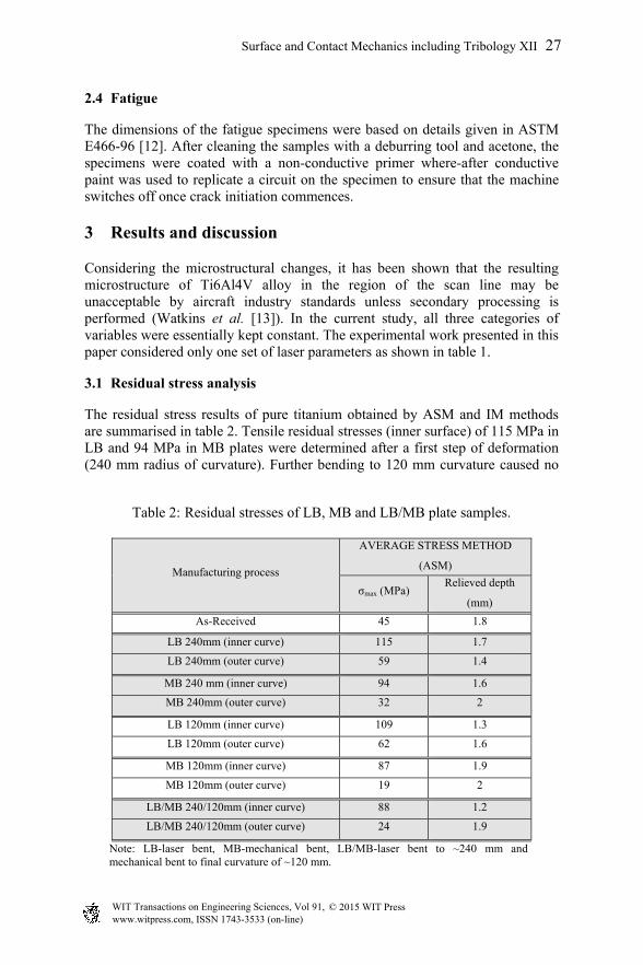
Table 2: Residual stresses of LB, MB and LB/MB plate samples.
Manufacturing process
AVERAGE STRESS METHOD
(ASM)
σmax (MPa) Relieved depth
(mm) As-Received 45 1.8
LB 240mm (inner curve) 115 1.7
LB 240mm (outer curve) 59 1.4
MB 240 mm (inner curve) 94 1.6
MB 240mm (outer curve) 32 2
LB 120mm (inner curve) 109 1.3
LB 120mm (outer curve) 62 1.6
MB 120mm (inner curve) 87 1.9
MB 120mm (outer curve) 19 2
LB/MB 240/120mm (inner curve) 88 1.2
LB/MB 240/120mm (outer curve) 24 1.9
Note: LB-laser bent, MB-mechanical bent, LB/MB-laser bent to ~240 mm and mechanical bent to final curvature of ~120 mm.
WIT Transactions on Engineering Sciences, Vol 91, www.witpress.com, ISSN 1743-3533 (on-line)
© 2015 WIT Press
Surface and Contact Mechanics including Tribology XII 27
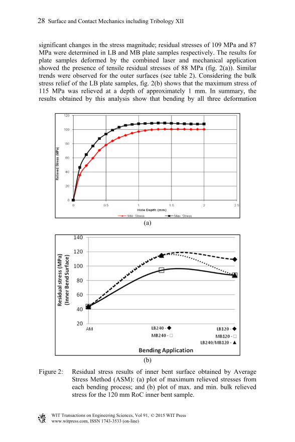
significant changes in the stress magnitude; residual stresses of 109 MPa and 87 MPa were determined in LB and MB plate samples respectively. The results for plate samples deformed by the combined laser and mechanical application showed the presence of tensile residual stresses of 88 MPa (fig. 2(a)). Similar trends were observed for the outer surfaces (see table 2). Considering the bulk stress relief of the LB plate samples, fig. 2(b) shows that the maximum stress of 115 MPa was relieved at a depth of approximately 1 mm. In summary, the results obtained by this analysis show that bending by all three deformation
(a)
(b)
Figure 2: Residual stress results of inner bent surface obtained by Average Stress Method (ASM): (a) plot of maximum relieved stresses from each bending process; and (b) plot of max. and min. bulk relieved stress for the 120 mm RoC inner bent sample.
WIT Transactions on Engineering Sciences, Vol 91, www.witpress.com, ISSN 1743-3533 (on-line)
© 2015 WIT Press
28 Surface and Contact Mechanics including Tribology XII
methods resulted in the formation of tensile residual stresses; measured residual stress magnitudes varied between 5 and 30% of the parent material’s yield strength value. The values obtained by the mechanical and combined bending applications did not show any significant variance in magnitude (namely: 87 versus. 88 MPa), while the LB process resulted in slightly higher residual stress values. It should be noted that deformation of Ti plate samples to the final curvature (~120 mm) did not reveal higher stress magnitudes in comparison to the first deformation step (~240 mm). In fact, stress relaxation occurred in both the LB and the MB plate samples (see table 2). Similarly, a stress relaxation from 115 MPa to 88 MPa was observed in the LB/MB plates after the first and second step deformation.
3.2 Metallography
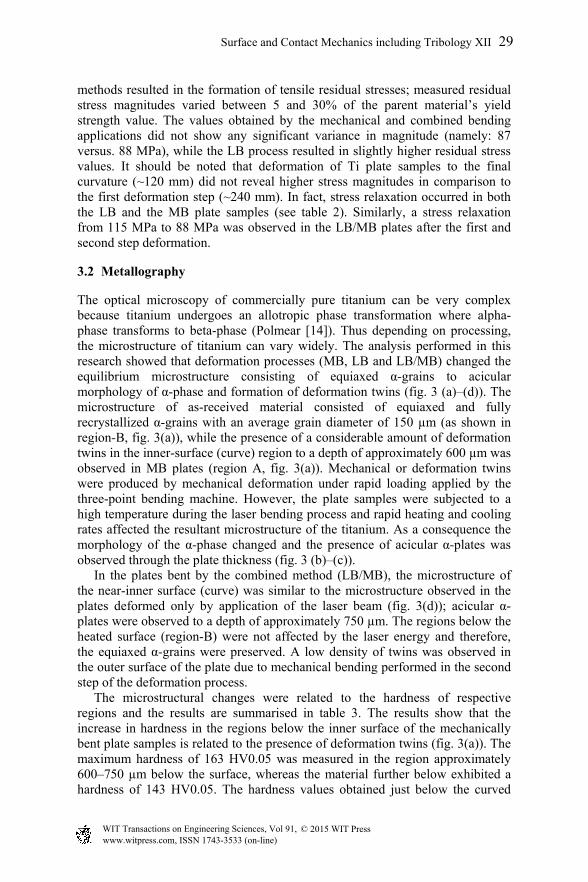
The optical microscopy of commercially pure titanium can be very complex because titanium undergoes an allotropic phase transformation where alpha-phase transforms to beta-phase (Polmear [14]). Thus depending on processing, the microstructure of titanium can vary widely. The analysis performed in this research showed that deformation processes (MB, LB and LB/MB) changed the equilibrium microstructure consisting of equiaxed α-grains to acicular morphology of α-phase and formation of deformation twins (fig. 3 (a)–(d)). The microstructure of as-received material consisted of equiaxed and fully recrystallized α-grains with an average grain diameter of 150 µm (as shown in region-B, fig. 3(a)), while the presence of a considerable amount of deformation twins in the inner-surface (curve) region to a depth of approximately 600 µm was observed in MB plates (region A, fig. 3(a)). Mechanical or deformation twins were produced by mechanical deformation under rapid loading applied by the three-point bending machine. However, the plate samples were subjected to a high temperature during the laser bending process and rapid heating and cooling rates affected the resultant microstructure of the titanium. As a consequence the morphology of the α-phase changed and the presence of acicular α-plates was observed through the plate thickness (fig. 3 (b)–(c)). In the plates bent by the combined method (LB/MB), the microstructure of the near-inner surface (curve) was similar to the microstructure observed in the plates deformed only by application of the laser beam (fig. 3(d)); acicular α-plates were observed to a depth of approximately 750 µm. The regions below the heated surface (region-B) were not affected by the laser energy and therefore, the equiaxed α-grains were preserved. A low density of twins was observed in the outer surface of the plate due to mechanical bending performed in the second step of the deformation process. The microstructural changes were related to the hardness of respective regions and the results are summarised in table 3. The results show that the increase in hardness in the regions below the inner surface of the mechanically bent plate samples is related to the presence of deformation twins (fig. 3(a)). The maximum hardness of 163 HV0.05 was measured in the region approximately 600–750 µm below the surface, whereas the material further below exhibited a hardness of 143 HV0.05. The hardness values obtained just below the curved
WIT Transactions on Engineering Sciences, Vol 91, www.witpress.com, ISSN 1743-3533 (on-line)
© 2015 WIT Press
Surface and Contact Mechanics including Tribology XII 29
surface showed scattered values, with the highest hardness being observed in the region having the denser twin structures. The increased hardness of the mechanically bent titanium plates was attributed to the twining deformation mechanism.
Figure 3: Optical micrographs of the near-surface region (region-A) and the region below (region-B) taken in the cross section perpendicular to the bending direction and laser scanning path: (a) MB plate: micrograph showing the presence of twins and equiaxed α-grains; (b), (c) LB plate: acicular α-phase at different magnifications; (d) LB/MB plate: acicular α-phase (near-surface) and equiaxed α-grains in the regions below.
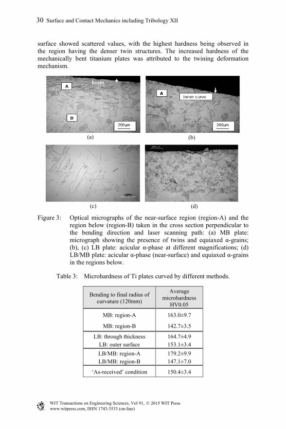
Table 3: Microhardness of Ti plates curved by different methods.
Bending to final radius of curvature (120mm)
Average microhardness
HV0.05
MB: region-A 163.0±9.7
MB: region-B 142.7±3.5
LB: through thickness LB: outer surface
164.7±4.9 153.1±3.4
LB/MB: region-A LB/MB: region-B
179.2±9.9 147.1±7.0
‘As-received’ condition 150.4±3.4
WIT Transactions on Engineering Sciences, Vol 91, www.witpress.com, ISSN 1743-3533 (on-line)
© 2015 WIT Press
30 Surface and Contact Mechanics including Tribology XII
(a) (b)
(c) (d)
Interestingly, the hardness achieved by the laser application was almost of the same magnitude as the hardness of the mechanically bent samples (region-A below inner surface) with a slight hardness increase experienced in the regions close to outer surface. However, the highest hardness values were observed in the samples bent by the combined method (LB/MB). An average hardness of 180 HV0.05 was measured in the region of approximately 700 µm below the surface (region-A) where the acicular type of α-phase was observed (fig. 3(d)). It should be mentioned that hardness increase has also been observed in laser bent titanium alloys (Ti6Al4V) investigated by Watkins et al. [13]. They found that oxygen uptake during processing in air contributes to the formation of an α-phase and an increase in micro-hardness on the irradiated surface.
3.3 Fatigue
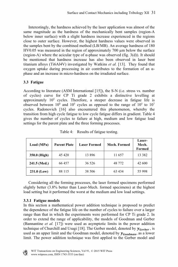
According to literature (ASM International [15]), the S-N (i.e. stress vs. number of cycles) curve for CP Ti grade 2 exhibits a distinctive levelling at approximately 105 cycles. Therefore, a steeper decrease in fatigue life is observed between 104 and 105 cycles as opposed to the range of 105 to 107 cycles. Radonovich [16] also encountered this phenomenon, whereby the transition from high cycle fatigue to low cycle fatigue differs in gradient. Table 4 gives the number of cycles to failure at high, medium and low fatigue load settings for the parent plate and the three forming processes.
Table 4: Results of fatigue testing.
Load (MPa) Parent Plate Laser Formed Mech. Formed Laser-Mech.
Formed
350.0 (High) 45 420 13 896 11 657 13 382
241.5 (Med.) 66 457 36 526 48 772 42 600
231.0 (Low) 88 115 38 506 63 434 55 998
Considering all the forming processes, the laser formed specimens performed slightly better (3.8% better than Laser-Mech. formed specimens) at the highest load setting but it performed the worst at the medium and low load settings.
3.3.1 Fatigue models In this section a mathematical power addition technique is proposed to predict the dependence of the fatigue life on the number of cycles to failure over a larger range than that in which the experiments were performed for CP Ti grade 2. In order to extend the range of applicability, the models of Goodman and Gerber (Bannantine et al. [17]) were used as asymptotic limits in the power addition technique of Churchill and Usagi [18]. The Gerber model, denoted by , is used as an upper limit and the Goodman model, denoted by , as a lower limit. The power addition technique was first applied to the Gerber model and
WIT Transactions on Engineering Sciences, Vol 91, www.witpress.com, ISSN 1743-3533 (on-line)
© 2015 WIT Press
Surface and Contact Mechanics including Tribology XII 31
the curve representing the actual data, denoted by, , and thereafter to the resulting equation and the Goodman model, yielding the following general unified equation:
⁄ ⁄. (2)
In eqn. (2), and denotes shifting exponents. The value of and that provided sufficient correspondence with the experimental data for all three forming processes was 50. The prototype predictive eqn. (2) for the fatigue life of CP Ti grade 2, subject to the three forming processes (together with the parent plate), can thus be simplified to
⁄
⁄
, (3)
with the coefficient values presented in table 5 for each of the forming processes. In equation (3) denotes the fatigue life and the number of cycles to failure.
Table 5: Proposed prototype prediction equations for CP Ti grade 2.
Parent plate -0.0005 352.47 900 -210-5 -0.00045 270.55
Laser -0.0005 352.47 900 -210-5 -0.00045 270.55 Mechanical -0.0005 352.47 900 -210-5 -0.00045 270.55
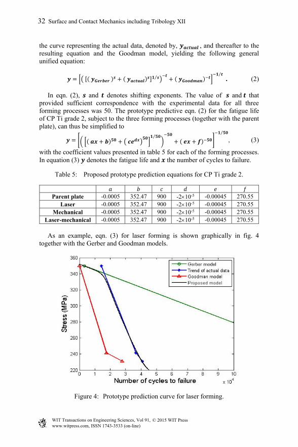
Laser-mechanical -0.0005 352.47 900 -210-5 -0.00045 270.55 As an example, eqn. (3) for laser forming is shown graphically in fig. 4 together with the Gerber and Goodman models.
Figure 4: Prototype prediction curve for laser forming.
WIT Transactions on Engineering Sciences, Vol 91, www.witpress.com, ISSN 1743-3533 (on-line)
© 2015 WIT Press
32 Surface and Contact Mechanics including Tribology XII
4 Conclusions
In this study three deformation methods were employed to bend CP pure titanium plate samples. Their effects were compared in terms of hardness, fatigue, residual stress state and microstructure. All three bending methods induced tensile residual stresses on both inner and outer surfaces that are considered detrimental to cyclic loading conditions. However, the magnitudes of these tensile stresses were significantly reduced after the mechanical process was employed in the combined application. This would render components manufactured by a combined process to have enhanced fatigue properties. Hence, the reduction in tensile residual stress magnitude together with the increased hardness due to change in microstructure would be of importance for industrial applications as both would translate to enhancing a component’s life expectancy. It was found that the primary factor influencing the fatigue life of CP Ti grade 2 specimens was the microstructure with the secondary factor being the residual stress, especially at medium to low fatigue load settings. Finally, the results show that a relationship exists between the bending process, induced residual stress and hardness resulting from the microstructural changes. A general equation is also presented that predicts the dependence of fatigue life on the number of cycles to failure for CP Ti grade 2 for each of the three forming processes considered.
References
[1] Els-Botes, A., McGrath, P.J. & Pienaar, H.J., Bending behaviour of laser-formed high-strength low-alloy (HSLA) steel sheet. R&D Journal, 23, pp. 35–38, 2007.
[2] Els-Botes, A., Fidder, H., Woudberg, S. & McGrath, P.J., Mechanical characterisation of the effect of various forming processes applied to Commercially Pure Titanium. Materials Characterization, 96, pp. 206–212, 2014.
[3] Fidder, H., Botes, A., Woudberg, S. & McGrath, P.J., Characterization of microstructure and fatigue life of CP titanium grade 2 specimens subject to various bending processes. Proc. of the 6th Int. Conf. on Contact and Surface, Siena, Italy, WIT Press, UK, pp. 25–33, 2013.
[4] McGrath, P.J. & Hughes, C.J., Experimental fatigue performance of laser-formed components. Optics and Lasers in Engineering, 45, 423–430, 2007.
[5] ASTM Standard E837-08e1, Standard test method for determining residual stresses by the Hole-Drilling Strain-Gage method. ASTM International, West Conshohocken, United States of America, 2008.
[6] Lu, J. (Ed.), Handbook of Measurement of Residual Stresses. Fairmount Press, Lilburn, 1996.
[7] Maher, W., Tong, K., Bampton, C., Bright, M., Wooten, J. & Rhodes, C., Laser forming of titanium and other metals is useable within metallurgical constraints. Proc. of ICALEO’ 98, Orlando, United States of America, Section E, pp. 121–130, 1998.
WIT Transactions on Engineering Sciences, Vol 91, www.witpress.com, ISSN 1743-3533 (on-line)
© 2015 WIT Press
Surface and Contact Mechanics including Tribology XII 33
[8] Schajer, G.S., Measurement of non-uniform residual stresses using the hole drilling method. Part I: Stress calculation procedures. J. Eng. Mater. Technol., 110, 338–343, 1988.
[9] Schajer, G.S., Measurement of non-uniform residual stresses using the hole drilling method. Part II: Practical application of the integral method. J. Eng. Mater. Technol., 110, 344–349, 1988.
[10] Gill, C.M., Fox, N. & Withers, P.J., Shakedown of deep cold rolling residual stresses in titanium alloys. J. Phys D: Appl Phys. 41, pp. 1–5, 2008.
[11] Van der Voort, G.F. & Van Geertruyden, W., Specimen preparation for electron backscattered diffraction. http://www.georgevandervoort.com/ met_papers/EBSD/EBSD_Specimen_Prep_Paper.pdf [Accessed 15 October 2010], 2006.
[12] ASTM Standard E466, 2002, “Standard Practice for Conducting Force Controlled Constant Amplitude Axial Fatigue Tests of Metallic Materials”, ASTM International, West Conshohocken, PA, 2002, DOI: 10.1520/E0466-07, www.astm.org.
[13] Watkins, K.G., Edwardson, S.P., Magee, J., Dearden, G., French, P., Cooke, R.L., Sidhu, J. & Calder, N.J., Laser forming of aerospace alloys. Paper 2001-01-2610. AMTC, Seattle, United States of America, 2001.
[14] Polmear, I.J., Light Alloys. Edward Arnold, London, 1981. [15] ASM International, Titanium A Technical Guide (2nd Edition ed.).
Materials Park: ASM International, 2007. [16] Radonovich, D.C., Methods of extrapolating low cycle fatigue data to high
stress amplitudes. MSc thesis, University of Central Florida, Florida, USA, 2007.
[17] Bannantine, J.A., Comer, J.J. & Handrock, J.L., Fundamentals of metal fatigue analysis. Prentice-Hall: New Jersey, 1990.
[18] Churchill, S.W. & Usagi, R., A general expression for the correlation of rates of transfer and other phenomena. AIChE, 18(6), pp. 1121–1128, 1972.
WIT Transactions on Engineering Sciences, Vol 91, www.witpress.com, ISSN 1743-3533 (on-line)
© 2015 WIT Press
34 Surface and Contact Mechanics including Tribology XII