multi-position hydronic heat dx coil€¦ · or heat pumps for use with either r22 or r410a ... an...
TRANSCRIPT
PRODUCT D IMENS IONS & SPEC IF ICAT IONS
AFM SER IES VAR IABLE SPEED MULT I - POS IT ION HYDRON IC HEAT DX CO I L
A IR HANDLERS
S T A N D A R D F E A T U R E S GENERAL The AFM Series variable speed Air Handler is equipped with electronically commutated constant torque motor (X-13). X13 offers constant torque over the range of static pressures, enhanced performance and energy efficiency. APPLICATION VERSATILITY Upflow or horizontal right as shipped (field-convertible for down-flow or horizontal left applications). ETL approved and can be ARI certified with most brands of air conditioners or heat pumps for use with either R22 or R410a when proper metering device is used. MOTOR X13 speeds and torques are controlled by software embedded in the motor to maintain constant torque. Motors are pre-programmed at the factory. CABINET Sturdy, galvanized steel cabinet with painted front panels. Cabinet fully insulated with 1/2” faced insulation to prevent sweating and mold growth, to encapsulate glass fibers, and to provide excellent R-value. Stick pins ensure insulation remains in place. Units ship with disposable filter in filter rack. BLOWER Direct drive variable-speed blowers circulate air quietly and efficiently. Variable speed motors allow for precise air volume selection. Motor speeds and torques programmed in the motor. Blowers mounted on rails so they can be easily removed for service. ELECTRONIC CONTROL BOARD An electronic board controls the functioning of the system reducing moving parts. The board provides for various hot water supply source connections and the blower time delay to maximize heat/cool extraction. As an enhanced feature the pump circulates hot water every 6 hours to prevent coil freeze during off cycle. MODULAR HYDRONIC HEAT KITS Heat kits available with either circuit breakers or terminal blocks. Available in 2, 3 & 4 row, providing 16,000 to 59,000 BTU’s of heat. Heat kits are easily installed in the field using molex plugs or can be ordered factory-installed. Freeze stat is standard, wired into circulating pump control circuit. Controls are accessible from the front for easy service. Electrical connections can be made from the top or left. Disconnect does not protrude through the wall panel. Fan time delay relay standard for increased efficiency. Heat kits are available with or without circulating pump and check valve. Units are provided with auxiliary relay for remote pump. Schrader ports are standard on water-out manifold, hose bib available as an option. DX COIL High efficiency rifled copper tubes/enhanced aluminum fins provide maximum heat transfer. All coils immersion tested at 500 psi then nitrogen pressurized and factory sealed for maximum reliability. Liquid-line Schrader allows pre-installation pressure testing. Available with either orifice or TXV metering device. Field-installable bolt-on TXVs are also available. Rugged, UV safe, GLP drain pan holds minimal condensate while eliminating the possibility of corrosion. Galvanized metal drain pan with bottom primary and secondary drain connections or alternate right side primary. All connections 3/4” FPT. Access door allows for coil cleaning. WARRANTY Five-year limited parts warranty. OPTIONS See options menu.
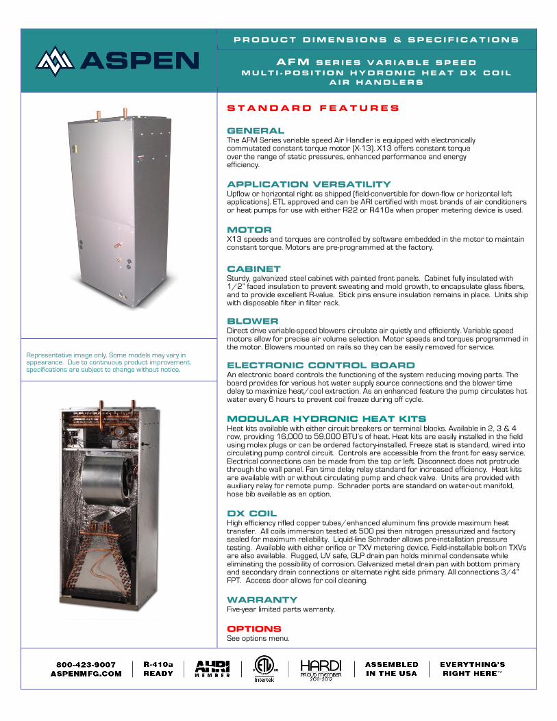
Representative image only. Some models may vary in appearance. Due to continuous product improvement, specifications are subject to change without notice.

AFM+W Spec. Revised 1/11/12. 2
HEAT ING AND COOL ING PERFORMANCE AND ELECTR ICAL DATA
UNIT MODEL
PERFORMANCE DATA ELECTRICAL DATA
HYDRONIC HEAT KIT MODEL
NOMINAL COOLING
HEATING COIL
HEATING CAPACITY
BTU/HR at 3 GPM MIN.CIR. AMPACITY
MAX FUSE OR
CIRCUIT BREAKER
ENTERING WATER TEMP
ROW SIZE 120º 140º 180º AFM18,
19 WC/T2SP/L 1.5
2 18”x12” 15700 22100 35200 4.1 15 AFM18,
19 WC/T3SP/L 3 18”x12” 19900 28000 44500
AFM24, 25 WC/T2SP/L
2.0 2 18”x12” 17800 25200 40100
4.1 15 AFM24, 25 WC/T3SP/L 3 18”x12” 22900 32300 51400
AFM30, 31 WC/T2SP/L
2.5
2 18”x12” 19500 27500 43900
7.4 15 AFM30, 31 WC/T3SP/L 3 18”x12” 25200 35600 56700
AFM30, 31 WC/T4SP/L 4 18”x12” 28400 40100 64000
AFM36, 37 WC/T2SP/L
3.0
2 18”x12” 20800 29500 47100
7.4 15 AFM36, 37 WC/T3SP/L 3 18”x12” 27100 38300 61100
AFM36, 37 WC/T4SP/L 4 18”x12” 30500 43200 68900
AFM42, 43 WC/T2LP/L
3.5
2 22”x14.5” 27100 38400 61200
12.6 15 AFM42, 43 WC/T3LP/L 3 22”x14.5” 33000 46700 74500
AFM42, 43 WC/T4LP/L 4 22”x14.5” 37100 52500 83800
AFM48, 49 WC/T2LP/L
4.0
2 22”x14.5” 28300 40000 63900
12.6 15 AFM48, 49 WC/T3LP/L 3 22”x14.5” 34400 48700 77800
AFM48, 49 WC/T4LP/L 4 22”x14.5” 38600 54700 87400
AFM60, 61 WC/T2LP/L
5.0
2 22”x14.5” 29800 42200 67300
12.6 15 AFM60, 61 WC/T3LP/L 3 22”x14.5” 36100 51200 81800
AFM60, 61 WC/T4LP/L 4 22”x14.5” 40500 57400 91800
BLOWER DATA
MODELS MOTOR
HP MOTOR
VOLTAGE SPEED TAP
CFM* V. EXTERNAL STATIC AMPS
0.10 0.20 0.30 0.40 0.50
AFM 18/19/24/25 1/3
120
TAP 5 900 853 797 738 673
4.8 TAP 4 670 646 613 592 553 TAP 3 500 476 452 421 400 TAP 2 900 853 797 738 673 TAP 1 400 381 360 339 312
AFM 30/31/36/37 1/2
TAP 5 1150 1087 1030 975 910
6.8 TAP 4 1080 1048 1010 960 895 TAP 3 900 862 825 796 745 TAP 2 700 663 632 600 552 TAP 1 500 473 449 421 395
AFM 42/43/48/60/61 1
TAP 5 1850 1806 1752 1700 1652
10.9 TAP 4 1704 1656 1600 1532 1479 TAP 3 1494 1461 1426 1400 1364 TAP 2 1350 1310 1272 1229 1175 TAP 1 676 652 621 600 559
* Dry coil

AFM+W Spec. Revised 1/11/12. 3
AIR HANDLER CHASSIS NOMENCLATURE
AFM 18 F -001
AFM = 120V X13 Motor Multi-Position Air Handler Nominal tonnage (MBTUH)
Metering device 4 = non-bleed A/C or H/P R410 TXV B = 20% bleed A/C or H/P R22 TXV
F = Flo-rater X = non-bleed A/C or H/P R22 TXV
Option Code
HYDRONIC HEAT KIT NOMENCLATURE
W C 2 S P
Water heat (hydronic)
C = Circuit Breaker T = Terminal Block
2- 2 Row Hydronic Coil
3- 3 Row Hydronic Coil
4- 4 Row Hydronic Coil
S= 18-37, Coil size- 18 x 12 L= 42-61, Coil size- 22 x 14.5
P= w/pump L= less pump
DIMENSIONS AND SPECIFICATIONS
MODEL A B C D E F G FILTER SIZE
PISTON SIZE
SHIP WEIGHT
(LBS)
SKID QTY
AFM18, 19+W*
21 [53]
49 1/4 [125]
18-3/4 [48]
12 [30]
18-1/2 [47]
7-1/4 [18]
10-1/4 [26] 16X20 0.055 99 4
AFM24, 25+W*
21 [53]
49 1/4 [125]
18-3/4 [48]
12 [30]
18-1/2 [47]
8-1/4 [21]
12-1/4 [31] 16X20 0.059 100 4
AFM30, 31+W*
21 [53]
49 1/4 [125]
18-3/4 [48]
12 [30]
18-1/2 [47]
8-1/4 [21]
14-1/4 [36] 16X20 0.068 118 4
AFM36, 37+W*
21 [53]
49 1/4 [125]
18-3/4 [48]
12 [30]
18-1/2 [47]
10-1/4 [26]
16-1/4 [41] 16X20 0.074 147 4
AFM42, 43+W*
24-1/2 [62]
57 [145]
22-1/4 [57]
14-3/4 (37)
22 [56]
11 [28]
16 [41] 20X20 0.080 153 3
AFM48, 49+W*
24-1/2 [62]
57 [145]
22-1/4 [57]
14-3/4 (37)
22 [56]
13 [33]
18 [46] 20X20 0.084 180 3
AFM60, 61+W*
24-1/2 [62]
57 [145]
22-1/4 [57]
14-3/4 (37)
22 [56]
15 [38]
20 [51] 20X20 0.092 200 3
ASPEN MANUFACTURING 281-441-6500 800-423-9007 WWW.ASPENMFG.COM