multi-objective robust design of new rotate barrel based
TRANSCRIPT

558 Technical Gazette 27, 2(2020), 558-566
ISSN 1330-3651 (Print), ISSN 1848-6339 (Online) https://doi.org/10.17559/TV-20190712135459 Original scientific paper
Multi-Objective Robust Design of New Rotate Barrel Based on Satisfaction Function
Hanzheng SUN, Zhengbao LEI, Yupeng HUANG, Jianghong Yu
Abstract: In this paper, a multi-objective robust design method based on satisfaction function was proposed by combining satisfaction function with Taguchi robust to solve the multi-objective optimization problem, which was easily interfered by noise factor. This method converted the signal-to-noise ratio of product quality characteristics into the expected smaller-the-better of Taguchi robust design, and realized the multi-objective robust design by weighted geometric mean, so as to solve the multi-objective optimization problem easily affected by noise factors. Under the premise of without changing rotate barrel of basic size by LS-DYNA FE model of rotary guardrail, the proposed method was carried out on the rotate barrel of multi-objective robust design, in order to solve the new rotary guardrail section parameter uncertain multi-objective optimization design. The results showed that the robust design of the new rotate barrel could resist the interference of the noise, the structure was more robust, and it conformed to the relevant laws and regulations by which was realized the purpose of lightweight of the new rotary guardrail. The research results had certain theoretical and engineering significance in improving the robustness of the new rotary guardrail.
Keywords: multi-objective; rotate barrel; satisfaction function; signal-to-noise ratio; Taguchi robust design
1 INTRODUCTION
Much of the current research in product design was driven by the fact that all real world engineering systems were comprised of uncertain parameters [1-3]. Therefore, the field of structural optimization needs to carry out more extensive research on design methods. For example, robust optimization which maximizes the robustness function, as well as the extreme case design [4-6]. Based on the orthogonal experimental design, Taguchi's robust design method played an important role in product design. In the early design stage, it could effectively reduce the sensitivity of product performance to noise fluctuation [7, 8]. However, guardrail products were not a single target in traffic safety settings. Therefore, it was necessary to develop a new robust method for products with multi-objective optimization design.
In practical engineering design, multi-objective optimization problems were usually transformed intosingle-objective problems by linear weighting, such asusing genetic algorithms to optimize the proxy model [9].Martin converted the optimization problem of multi-objective function corresponding to multi-operating load into the optimization problem of single objective functionby adopting the weighted compromise programming method [10]. McDonald and Heller incorporated robustdesigned strategies to develop an iterative 2D FEoptimization procedure, which was used to decide on precise shape of a hole in a plate to maximize its fatiguelife [11]. Ozturk proposed an efficient method for fatiguebased shape optimization to obtain the robust design of an oil sump shape with consideration of the variation of theclamping forces [12].
However the premise of these methods was that the research objects had not considered the influence of noise factors on products in real time. Therefore, in this paper the maximum acceleration of the sedan (X, Y, Z) direction and the maximum lateral deviation of the guardrail after the passenger hit the guardrail were taken as the objective function. Through difference analysis and Variance analysis, the influence of noise factor was considered, a multi-objective robust design method put forward based on the satisfaction function, the satisfaction function method
was introduced into the rotate barrel of parameteroptimization design of the pipe cross section. It helped to reduce the new type of rotate barrel structure noise factorson the sensitivity of random fluctuations, improved thenew type of rotary guardrail of design parameters andobjective function robustness, achieved the goal oflightweight structure.
2 ROTARY GUARDRAIL ROBUSTNESS PROBLEM WITHMULTI-OBJECTIVE SATISFACTION
Optimization objectives such as guardrail productswere multiple targets. In the optimization goal, structureusually needed to meet different design requirements at thesame time, and set the traffic safety guardrail products asan example. It did not just want to control the vehiclecollision guardrail in the three directions (X, Y, Z), whichmust be less than the maximum acceleration ORA of 20 g,but also required guardrail maximum offset ∆was less than1000 mm. Therefore, for the problem of multi-objectiveoptimization design, the maximum deviation of guardrail should not exceed the threshold in the specification on thepremise that the maximum acceleration of runawayvehicles was less than the standard value. Taken the rotatebarrel as example, it was an important part of the rotaryguardrail, when uncontrolled vehicle hit rotary guardrail byrotate barrel turning around columns, the vehicle drives outof the exercise direction of the return to normal, and it willrotate barrel between the above two guardrail beams.
Figure 1 New rotate barrel: (a) New rotate barrel elevation; (b) New rotate barrel section
RETRACTED

Hanzheng SUN et al.: Multi-Objective Robust Design of New Rotate Barrel Based on Satisfaction Function
Tehnički vjesnik 27, 2(2020), 558-566 559
Combined with the traditional rotary guardrail, the use of the process suffered from runaway vehicle affected, a new rotate barrel structure designed, and the basic configuration is shown in Fig. 1. The energy absorbing cavity structure in the outer circumference area of the upper part of rotate barrel was used to absorb the collision energy of runaway vehicles, and the middle part was used to drive the runaway vehicles to run in the normal track by rotating around the column, to achieve the purpose of using the guardrail.
3 NEW ROTARY GUARDRAIL FE MODE ESTABLISHMENT AND VEHICLE FE MODEL VERIFICATION
3.1 FE Models of New Rotary Guardrail
LS-DNYA was used to establish FE models of new rotary guardrail and vehicle, such as a new type of rotate barrel of the B-T differentiate four node shell element. The grid cell size was 15 × 15 mm, vehicle FE model was suitable for large deformation of the structure, which was used to 3 points of integral unit. The grid size of model units was controlled within 15 mm, each grid unit warping angle of maximum angle control in less than 15° and 135°, the triangular mesh number was controlled within 5%. Fig. 2 shows the FE model of the new rotate barrel and the new rotary guardrail.
Figure 2 New Rotary guardrail FE model: (a) new rotate barrel FE model; (b) new rotary guardrail FE model.
3.2 Validation of Vehicle FE Modal for Topology Optimization
The accuracy of the FE model of the vehicle was directly related to the reliability of the simulation results. Before the simulation test, this paper intended to comprehensively evaluate the correctness of the vehicle FE model by qualitative and quantitative aspects of the FE model of the 10 t passenger and the 1,5 t sedan. As shown in Tab. 1, the geometric parameters tables of 10 t passenger and 1,5 t sedan were given, the relevant parameters shown in Tab. 1, the FE models of 10 t passenger and 1,5 sedan were established. When the uncontrolled vehicle collides with the guardrail, there is contact between them. In order to prevent the contact between the out-of-control vehicle and the guardrail, the guardrail and the uncontrolled vehicle model adopted Automatic-Single-Surface, the contact method that defines the self-contact between the guardrail and the out of control vehicle. At the same time, the contact between the test vehicle and the guardrail is adopted. By definition of Automatic-Surface-to-Surface, the set dynamic and static friction coefficients were 0,30 and 0,20 [13].
Figure 3 Real passenger and FE model: (a) Real passenger; (b) FE passenger
Figure 4 Real sedan and FE model: (a) Real sedan; (b) FE sedan
As shown in Fig. 3, Fig. 4, the real vehicle and FE vehicle of the 10 t passenger and the 1,5 t sedan, and the collision test conditions described in Tab. 1 were set with reference to the relevant specifications [14, 15].
Table 1 The main parameter of vehicle model
Vehicle type Vehicle quality / t Vehicle size / mm Vehicle centroid coordinates / mm Length Width Height X Y Z
Passenger 10 9020 2440 2880 4510 1220 1100 Sedan 1,5 3750 1586 1433 −1870 23 492
Table 2 Material parameters of vehicle and guardrail
Simulationmodal Density / kg/m3 Elasticity modulus / MPa Poisson ratio / - Yield strength / MPa Failure equivalent Plastic strain
Passenger 7870 2,10×10⁵ 0,30 235 0,75 Sedan 7870 2,10×10⁵ 0,30 235 0,75
Rotate barrel 150 5,78×10³ 0,25 23.5 0,22 column 7870 2,10×10⁵ 0,30 235 0,75
Profiled bar 7870 2,10×10⁵ 0,30 235 0,75 U Block 7870 2,10×10⁵ 0,30 235 0,75
RETRACTED

Hanzheng SUN et al.: Multi-Objective Robust Design of New Rotate Barrel Based on Satisfaction Function
560 Technical Gazette 27, 2(2020), 558-566
3.2.1 Verification of Passenger FE Model
Fig. 5, Fig. 6 were the trajectories of the real passenger and simulate passenger impact guardrail. It could be seen that during the collision process between the guardrail and the passenger under no abnormal driving conditions, the driving trajectory was the same.
Figure 5 The motion condition of real passenger
Herein, the maximum acceleration values at the center
of mass of the vehicle were used for quantitative
evaluation. Fig. 7 presents the acceleration curves in (X, Y, Z) at the mass center of the real passenger test, while their maximum values were ORAx = 2,65g, ORAY = 1,94g, and ORAz = 2,93g, respectively. The acceleration curves in the three directions at the mass center of the simulated test passenger are depicted in Fig. 8, and the maximum acceleration values were ORAx = 2,75g, ORAY = 2,04g, and ORAz = 3,05g. By comparing Fig. 7, Fig. 8, it was revealed that the maximum acceleration error in various directions did not exceed 5%.
Figure 6The motion condition of simulation passenger
Figure 7 Experimental aspect to the acceleration of the passenger train: (a) X-direction acceleration; (b) Y-direction acceleration; (c) Z-direction acceleration
Figure 8 Simulation aspect to the acceleration of the passenger train: (a) X-direction acceleration; (b) Y-direction acceleration; (c) Z-direction acceleration
3.1.2 Verification of Sedan Car FE Model
Fig. 9, Fig. 10 were respectively the 1,5 t sedan simulation test and the running track of the real vehicle test vehicle. It could be seen that during the collision between the vehicle and the guardrail, the vehicle did not show the
phenomenon of drilling and smashing, and the collision trajectory of the vehicle and the guardrail was the same. As could be seen from Fig. 11, the damage positions of the actual and simulated were the same.
Fig. 12, Fig. 13 are divided into the maximum acceleration curves in the three directions of the vehicle's
RETRACTED

Hanzheng SUN et al.: Multi-Objective Robust Design of New Rotate Barrel Based on Satisfaction Function
Tehnički vjesnik 27, 2(2020), 558-566 561
center of mass in the actual sedan and simulated sedan crash test. The actual vehicle mass acceleration values were: ORAX = 12,67g, ORAY = 12,38g, ORAZ = 11,41g. The acceleration value of the simulated vehicle centroid was: ORAX = 13,25g, ORAY = 13,01g, ORAZ = 12,02g. It could be seen that the error values of the maximum acceleration values in the three directions of the real vehicle and the simulated vehicle were all controlled within 5%.
Figure 9 The motion condition of simulation sedan
Figure 10 The motion condition of real sedan
Figure 11 Damage comparison diagram of real sedan and simulation sedan
Figure 12 Experimental aspect to the acceleration of the real sedan: (a) X-direction acceleration; (b) Y-direction acceleration; (c) Z-direction acceleration
Figure 13 Simulation aspect to the acceleration of the sedan: (a) X-direction acceleration; (b) Y-direction acceleration: (c) Z-direction acceleration
Through the qualitative and quantitative analysis of the
FE model of the 1,5 t sedan, the FE model of the 1,5 t sedan, the actual vehicle running state and damage degree were basically consistent with the real vehicle, and the acceleration error was within 5%, so the 1,5 t sedan FE was reliable in future simulation work.
In the course of rotate barrel and guardrail rushing, it was used Cowper-Symonds constitutive model taking strain rate effect into account:
( )( )1
Y 0 eff1P P
n' f
Cεσ σ ε
= + +
(1)
where σY is the stress considering strain rate ε', C and P
represent material strain rate parameter, σ0 is single-axis tensile stress, eff( )p
nf ε is the hardening function based on the effective plastic strain [16]. In this paper Eq. (1) C is 40, P is 5. 4 SATISFACTION FUNCTION MULTI-OBJECTIVE
ROBUSTNESS DESIGN METHOD
The concept of satisfaction was to learn from the multi-objective decision making problem in statistics. After one thing appeared, it was judged whether satisfied or not based on people's subjective desires. As shown in Fig. 14, a satisfactory procedure was indicated by q, q = 1 was fully satisfied, and q =1 was completely dissatisfied, where
(0, 1)q∈ .
RETRACTED
Hanzheng SUN et al.: Multi-Objective Robust Design of New Rotate Barrel Based on Satisfaction Function
562 Technical Gazette 27, 2(2020), 558-566
, max
, max
1
1 exp 2 4i
i i
il i
qC CC C
= −
+ − −
(2)
In Eq. (2), Ci represented the response value of each
single target, qi represented the satisfaction value corresponding to the different response values of Ci, Ci, max was the lowest satisfaction value of the ith sub-target, and Cil was the ideal value of the satisfaction of the ith sub-target satisfaction. 4.1 Signal-to-Noise Ratio
Signal-to-noise ratio is an indicator used to measure fluctuations in product data. A larger signal-to-noise ratio means less quality loss, and the product is more robust. Signal-to-noise ratio (SNR) could be classified from its characteristics: nominal-the-better characteristic (NTB), smaller-the-better characteristic (STB), larger-the-better characteristic (LTB). Assumed that the measured values of the quality characteristics of the product were y1, y2, …, yn, and T were the target values. Then the signal-to-noise ratio S/N of the output response could be expressed as:
2
1
2
1
2
1
110lg STB
1 110lg LTB
110lg ( ) NTB
n
uu
n
uu
n
nu
yn
S Nn y
y Tn
=
=
=
−
= −
− −
∑
∑
∑
(3)
In Eq. (3): n was the number of experimental
repetitions, yi was the target value measured by the ithrepeated experiment, and S/N was the target signal-to-noise ratio value.
The satisfaction function method converted a single response function Yi(i = 1, 2, 3, …, l) into a specific quantitative evaluation function di(0 ≤ di ≤ 1) by each experiment. Combined with the product quality characteristics response, we could know that the smaller-the-better characteristic (STB) satisfaction function was:
( )
, min
, min, min
1
0
0
i
i ii i i i i
i i
i i
Y
Y Ud Y Y Y U r
Y U
Y U
≤ −= ≤ ≤ ≥ − ≥
(4)
In Eq. (4): r, s, and t were the weighting factors of the
satisfaction functions, Ui and Li were the upper and lower limits of the output response, respectively. 4.2 Multi-objective Robust Mathematical Model Based on
SNR Satisfaction Function
By combined satisfaction function and signal-to-noise ratio, a new multi-objective robustness design model was
established to convert the signal-to-noise ratio of different product quality characteristics into satisfaction, while at the same time it is satisfying the STB in the robust design. Although the satisfaction function of STB was converted, its expression could be defined as Eq. (5):
min
minmin max
max min
max
1
( )
0
id
η η
η ηη η η η
η ηη η
≤ −= < < − ≤
(5)
Where: di(η) was the satisfaction value of the output
response function Yi, and 0 ( ) 1id η≤ ≤ , 0 1r≤ ≤ , ηmax, andηmin were the upper and lower limits of the signal-to-noise ratio compared with the output response value, and the values were calculated by actual conditions and related data. When evaluating the satisfaction of multiple goals, it was necessary to convert multiple single-objective satisfaction functions into a total satisfaction function for comprehensive evaluation, and then the overall satisfaction
)1,0()( ∈xD could be expressed as Eq. (6)
( )1
1 2( ) × ... kkD x d d d= × × (6)
where: dk was the satisfaction of the jth sub-reaction, where j = 1, 2, …, k. 4.3 Optimization Design of Section Parameters of Rotate
Barrel of New Rotary Guardrail
According to Standard for Safety performance Evaluation of Highway Barrier JTG B05-01-2013 [14], the safety performance of the guardrail should have the function of blocking, buffering and guiding. It was forbidden for any vehicle to cross, climb or ride guardrail in any form. In this paper, the maximum acceleration ORA in the (X, Y, Z) directions of the sedan's center of mass and the maximum lateral offset Δ of the guardrail after the collision of the passenger were used as the objective function. Therefore, in order to unify the evaluation index, the maximum acceleration ORA and the maximum lateral offset Δ could be dimensionlessly processed. (This paper stipulated the maximum acceleration ORA ≥ 16 g and the maximum lateral displacement Δ ≥ 800 mm, and the satisfaction value of the output response was 0, and the overall conversion was the overall satisfaction as the evaluation index). 4.3.1 Determination of Orthogonal Test Factors and Levels
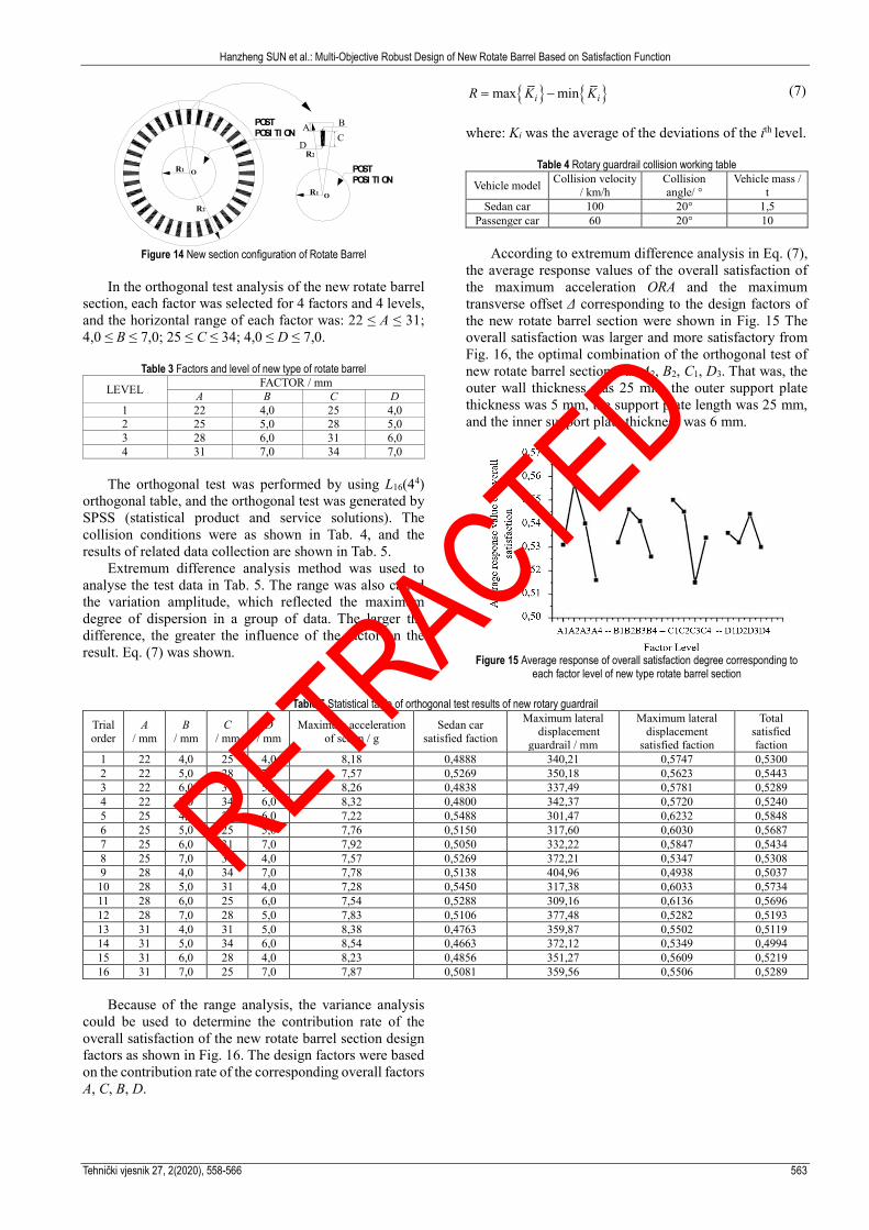
Under the premise of ensuring, the inner diameter is r1 = 150 mm, and outer diameter is r2 = 150 mm of the new rotate barrel. The design factors for the cross-section configuration of the new rotate barrel were determined initially-the outer wall thickness A, the outer support plate thickness B, the support plate length C, and the inner support plate thickness D, which were the experimental factors for the orthogonal test. A new rotate barrel section configuration was shown in Fig. 14.
RETRACTED
Hanzheng SUN et al.: Multi-Objective Robust Design of New Rotate Barrel Based on Satisfaction Function
Tehnički vjesnik 27, 2(2020), 558-566 563
Figure 14 New section configuration of Rotate Barrel
In the orthogonal test analysis of the new rotate barrel
section, each factor was selected for 4 factors and 4 levels, and the horizontal range of each factor was: 22 ≤ A ≤ 31; 4,0 ≤ B ≤ 7,0; 25 ≤ C ≤ 34; 4,0 ≤ D ≤ 7,0.
Table 3 Factors and level of new type of rotate barrel
LEVEL FACTOR / mm A B C D
1 22 4,0 25 4,0 2 25 5,0 28 5,0 3 28 6,0 31 6,0 4 31 7,0 34 7,0
The orthogonal test was performed by using L16(44)
orthogonal table, and the orthogonal test was generated by SPSS (statistical product and service solutions). The collision conditions were as shown in Tab. 4, and the results of related data collection are shown in Tab. 5.
Extremum difference analysis method was used to analyse the test data in Tab. 5. The range was also called the variation amplitude, which reflected the maximum degree of dispersion in a group of data. The larger the difference, the greater the influence of the factor on the result. Eq. (7) was shown.
{ } { }max mini iR K K= − (7)
where: Ki was the average of the deviations of the ith level.
Table 4 Rotary guardrail collision working table
Vehicle model Collision velocity / km/h
Collision angle/ °
Vehicle mass / t
Sedan car 100 20° 1,5 Passenger car 60 20° 10
According to extremum difference analysis in Eq. (7),
the average response values of the overall satisfaction of the maximum acceleration ORA and the maximum transverse offset Δ corresponding to the design factors of the new rotate barrel section were shown in Fig. 15 The overall satisfaction was larger and more satisfactory from Fig. 16, the optimal combination of the orthogonal test of new rotate barrel section was A2, B2, C1, D3. That was, the outer wall thickness was 25 mm, the outer support plate thickness was 5 mm, the support plate length was 25 mm, and the inner support plate thickness was 6 mm.
Figure 15 Average response of overall satisfaction degree corresponding to
each factor level of new type rotate barrel section
Table 5 Statistical table of orthogonal test results of new rotary guardrail
Trial order
A / mm
B / mm
C / mm
D / mm
Maximum acceleration of sedan / g
Sedan car satisfied faction
Maximum lateral displacement
guardrail / mm
Maximum lateral displacement
satisfied faction
Total satisfied faction
1 22 4,0 25 4,0 8,18 0,4888 340,21 0,5747 0,5300 2 22 5,0 28 7,0 7,57 0,5269 350,18 0,5623 0,5443 3 22 6,0 31 5,0 8,26 0,4838 337,49 0,5781 0,5289 4 22 7,0 34 6,0 8,32 0,4800 342,37 0,5720 0,5240 5 25 4,0 28 6,0 7,22 0,5488 301,47 0,6232 0,5848 6 25 5,0 25 5,0 7,76 0,5150 317,60 0,6030 0,5687 7 25 6,0 31 7,0 7,92 0,5050 332,22 0,5847 0,5434 8 25 7,0 34 4,0 7,57 0,5269 372,21 0,5347 0,5308 9 28 4,0 34 7,0 7,78 0,5138 404,96 0,4938 0,5037
10 28 5,0 31 4,0 7,28 0,5450 317,38 0,6033 0,5734 11 28 6,0 25 6,0 7,54 0,5288 309,16 0,6136 0,5696 12 28 7,0 28 5,0 7,83 0,5106 377,48 0,5282 0,5193 13 31 4,0 31 5,0 8,38 0,4763 359,87 0,5502 0,5119 14 31 5,0 34 6,0 8,54 0,4663 372,12 0,5349 0,4994 15 31 6,0 28 4,0 8,23 0,4856 351,27 0,5609 0,5219 16 31 7,0 25 7,0 7,87 0,5081 359,56 0,5506 0,5289
Because of the range analysis, the variance analysis could be used to determine the contribution rate of the overall satisfaction of the new rotate barrel section design factors as shown in Fig. 16. The design factors were based on the contribution rate of the corresponding overall factors A, C, B, D.
POSTPOSI TI ON
POSTPOSI TI ON
A B
D
R1
R2
R1
O
O
CR2
RETRACTED

Hanzheng SUN et al.: Multi-Objective Robust Design of New Rotate Barrel Based on Satisfaction Function
564 Technical Gazette 27, 2(2020), 558-566
Figure 16 Contribution rate of overall satisfaction degree corresponding to each design factor of the new rotate barrel section
4.4 Multi-Target Robust Design of New Rotary Guardrail 4.4.1 Controllable Factors and Noise Factor Selection
The traditional parameter optimization design did not consider the influence of the noise factor on the test results, but the noise factor exists in real time. In order to improve the robustness of the new rotate barrel structure, according to the variance analysis shown in Fig. 17, the two factors A and C were the controllable factors of the robust design, as shown in Tab. 6.
According to the vehicle quality tolerance error, the collision speed tolerance error, and the collision angle tolerance error specified in the literature [15, 16], the multi-objective robustness design was performed as shown in Tab. 7.
Table 6 Controllable factor level table for robust design of new rotate barrel section
LEVEL FACTOR / mm A C
1 22 25 2 25 28 3 28 31 4 31 34
Table 7 Noise factor table for robust design of new rotary guardrail
LEVEL FACTOR D E F
1 −75 0 −1 2 0 4 1.5
D - Permissible errors in vehicle quality, kg; E - Permissible errors in collision speed, km/h; F - Permissible errors in collision angle. 4.4.2 Optimal Combination Analysis of Multi-Objective
Robust Design
The mean maximum acceleration, the mean maximum offset of guardrail, and Overall satisfaction of the new rotate barrel obtained after multi-objective robustness optimization design were shown in Tab. 8.
By extremum difference analysis method as shown in Fig. 18, the optimal combination of controllable factors in the design of robustness was: A3, C3, the outer wall thickness was 28 mm, the support plate length was 31 mm.
By variance analysis, the corresponding contribution rate of the overall satisfaction corresponding to each controllable factor was shown in Fig. 18. The contribution rate was C and A by the orthogonal test. The final determination of the optimal combination of robustness was the outer wall thickness 28 mm, the outer support plate thickness 5 mm, the support plate length 31 mm and the inner support plate thickness 6 mm.
Figure 17 Average response value of total satisfaction of controllable factors in robust design of new rotary guardrail
Figure 18 Contribution rate of overall satisfaction degree corresponding to new rotary guardrail
Figure 19 Optimization of the sedan before the center of mass acceleration: (a) X-direction acceleration; (b) Y-direction acceleration; (c) Z-direction acceleration
RETRACTED

Hanzheng SUN et al.: Multi-Objective Robust Design of New Rotate Barrel Based on Satisfaction Function
Tehnički vjesnik 27, 2(2020), 558-566 565
Table 8 Average acceleration, maximum deviation of guardrail and overall satisfaction response value
Trail order Mean maximum acceleration / g Mean maximum offset of guardrail /mm Overall satisfaction a Sn2 D1 (sn1) △x Sn2 D2 (sn2)
01 7,23 −17,18 0,81 361,26 −51,16 0,29 0,48 02 7,54 −17,55 0,77 347,68 −50,82 0,30 0,48 03 7,35 −17,33 0,79 324,64 −50,23 0,33 0,51 04 7,13 −17,06 0,83 372,19 −51,42 0,28 0,48 05 7,04 −16,95 0,84 383,16 −51,67 0,27 0,47 06 7,08 −17,00 0,83 340,86 −50,65 0,31 0,51 07 7,15 −17,09 0,82 349,40 −50,87 0,30 0,49 08 7,04 −16,95 0,84 351,27 −50,91 0,30 0,50 09 7,64 −17,67 0,75 323,45 −50,20 0,33 0,50 10 7,11 −17,03 0,83 334,61 −50,49 0,31 0,51 11 7,08 −17,00 0,83 292,90 −49,34 0,36 0,55 12 7,06 −16,97 0,84 333,15 −50,45 0,32 0,51 13 7,26 −17,22 0,81 403,86 −52,13 0,25 0,45 14 7,12 −17,05 0,83 384,89 −51,71 0,26 0,47 15 7,49 −17,49 0,77 295,53 −49,41 0,37 0,53 16 6,97 −16,86 0,85 367,80 −51,31 0,28 0,49
5 DISCUSSION
The traditional robust design method belonged to the single-objective optimization problem, which was difficult to achieve the multi-objective optimization and did not consider the impact of noise factors on products in real time. However, noise factors existed in actual product design. This method could solve the optimization problem of multi-objective robust design with noise factor. On the premise of keeping the basic size of rotate barrel section unchanged, the relevant parameters were obtained by adopting the robustness design of multi-objective satisfaction function considering the noise factor. The final determination of the optimal combination of robustness was: the outer wall thickness 28 mm, the outer support plate thickness 5 mm, the support plate length 31 mm and the inner support plate thickness 6 mm. The cross section
parameters of rotate barrel obtained by orthogonal experiment without noise, the outer wall thickness was 25 mm, and the outer support plate thickness was 5 mm. The support plate length was 25 mm, and the inner support plate thickness was 6 mm. By using acceleration ORA and its maximum offset as a double evaluation index, there is a decline in the knowable acceleration, and guardrail maximum offset. Before optimization the acceleration value at the center of mass of sedan was ORAx = 7,5g, ORAY = 8,88g, ORAZ = 5,24g as shown in Fig. 19. The passenger maximum deviation of guardrail was 398,46 mm. The optimized acceleration value at the center of mass of sedan was ORAx = 7,01g, ORAY = 6,73g, ORAZ = 4,51g as shown in Fig. 20, and the passenger maximum deviation of guardrail was 345,98 mm. The maximum offset declined 52,48 mm.
Figure 20 Optimization of the sedan after the center of mass acceleration: (a) X-direction acceleration; (b) Y-direction acceleration; (c) Z-direction acceleration
6 CONCLUSIONS
Aimed at the multi-objective optimization and the influence of noise problem, this paper combined the signal-to-noise ratio and satisfaction function to establish a multi-objective robust design method based on satisfaction function, and utilized the multi-objective robust design method. The satisfaction function of the multi-objective robust design of the new rotating cylinder was studied. The robust design of the new rotating cylinder after the response mean and response standard deviation was reduced, and the collision FE analysis was set according to the relevant specifications. In the collision analysis of the
new rotating guardrail with and without noise factors,the maximum acceleration and maximum deviation of the guardrail were reduced by 2,15 g and 52,48 mm, achieving the goal of light weighting. Acknowledgments
The research was supported by the National Natural Science Foundation of China (No. 51675059), Key Research and Development Project of Science and Technology Plan of Hunan Province (No. 2019SK2174), Hunan Provincial Innovation Foundation for Postgraduate (No. CX20190641). The authors also would like to thank
RETRACTED

Hanzheng SUN et al.: Multi-Objective Robust Design of New Rotate Barrel Based on Satisfaction Function
566 Technical Gazette 27, 2(2020), 558-566
the Large Structural Crash Testing Laboratory for its support.
7 REFERENCES
[1] Lee, S. H. & Chen, W. (2009).A Comparative Study ofUncertainty Propagation Methods for Blacks-Box-TypeProblems. Struct Multidiscip Optim, 37(3), 239-253.https://doi.org/10.1007/s00158-008-0234-7
[2] Schueller, G. I. & Jensen, H. A. (2008).ComputationalMethods in Optimization Considering Uncertainties-AnOverview. Comput Methods Appl Mech Engrg, 198(1), 2-13.https://doi.org/10.1016/j.cma.2008.05.004
[3] Moller, B. & Beer, M. (2008). Engineering ComputationUnder Uncertainly-Capabilities of Non-Traditional Models.Comput Struct, 86(10), 1024-1041.https://doi.org/10.1016/j.compstruc.2007.05.041
[4] Hashimoto, D. & Kanno, Y. (2015). A semidefiniteprogramming approach to robust truss topology optimization under uncertainly in locations of nodes. Struct MultidiscipOptim, 51, 439-461. https://doi.org/10.1007/s00158-014-1146-3
[5] Ohsaki, M. & Katsura, M. (2010). A random samplingapproach to worst-case design of structures. Struct MultidiscOptim, 46(1), 27-39. https://doi.org/10.1007/s00158-011-0752-6
[6] Takezawa, A., Nii, S., Kitamura, M., & Kogiso, N. (2011).Topology optimization for worst load conditions based onthe eigenvalue analysis of an aggregated linear system.Comp Meth Appl Mech Engrg, 200(25-28), 2268-2281.https://doi.org/10.1016/j.cma.2011.03.008
[7] Abhiram, D. R. & Gangulir, H. D. (2018). Robust design ofsmall unmanned helicopter for hover performance usingTaguchi method. Journal of Aircraft, 55(4), 1746-1753.https://doi.org/10.2514/1.C034539
[8] Lee, S, Kim, K, Cho, S, et al. (2014). Optimal design ofinterior permanent magnet synchronous motor consideringthe manufacturing tolerances using Taguchi robust design.IET Electric Power Applications, 8(1), 23-28.https://doi.org/10.1049/iet-epa.2013.0109
[9] Sekulski, Z. (2010). Multi-objective topology and sizeoptimization of high-speed vehicle-passenger catamaranstructure by genetic algorithm. Marine Structures, 23(4),405-433. https://doi.org/10.1016/j.marstruc.2010.10.001
[10] Martin, M. A., Cuadrado, M. L., & Romero, C. (2011).Computing efficient financial strategies: An extendedcompromise programming approach. Applied Mathematicsand Computation, 217(19), 7831-7837.https://doi.org/10.1016/j.amc.2011.02.106
[11] McDonald, M. & Heller, M. (2004). Robust shapeoptimization of notches for fatigue-life extension. StructMultidiscip Optim, 28, 55-68.https://doi.org/10.1007/s00158-004-0437-5
[12] Ozturk, U. E. (2011). Efficient method for fatigue basedoptimization of the oil sump carrying a differential case infour wheel drive vehicles. Struct Multidiscip Optim, 44, 823-830. https://doi.org/10.1007/s00158-011-0678-z
[13] Yin, H., Xiao, Y., & Wen, G. (2016). Multi-objective robustoptimization of foam-filled bionic thin-walled structures.Thin-Walled Structures, 109, 332-343.https://doi.org/10.1016/j.tws.2016.10.011
[14] JTG B05-01-2013: Standard for Safety performanceEvaluation of Highway Barrier. China: Ministry ofTransport of the People's Republic of China.
[15] DB 33/T 888-2013: Specification for layout of rotaryguardrail. China: Quality and Technology Supervision ofZhejiang Province.
[16] Peng, Y., Deng, W., & Xu, P. (2015). Study on the collisionperformance of a composite energy-absorbing structures forsubway vehicle. Thin-Walled Structures, 94, 663-672.https://doi.org/10.1016/j.tws.2015.05.016
Contact information:
Hanzheng SUN Large Structural Crash Testing Laboratory, Changsha University of Science & Technology, Changsha 410114, China E-mail: [email protected]
Zhengbao LEI (Corresponding author) Large Structural Crash Testing Laboratory, Changsha University of Science & Technology, Changsha 410114, China E-mail: [email protected]
Yupeng HUANG Large Structural Crash Testing Laboratory, Changsha University of Science & Technology, Changsha 410114, China
Jianghong YU Large Structural Crash Testing Laboratory, Changsha University of Science & Technology, Changsha 410114, China
RETRACTED
