mub climatic control hc - watts water · 4 . gb . 1 . application climaticcontrol-hc is developed...
TRANSCRIPT

1
INSTALLATION AND USER GUIDE GB CLIMATIC CONTROL WITH HEAT&COOL FUNCTION ----------------------------------------------------- 3-26
GUIDE D’INSTALLATION ET D’UTILISATION FR REGULATION POUR VANNE MELANGEUSE POUR INSTALLATION CHAUFFAGE & REVERSIBLE 27-51
MONTAGE UND BEDIENUNGSANLEITUNG DE HEIZEN- UND KÜHLEN REGLER CLIMATICCONTROL-HC 52-75
CLIMATIC CONTROL HC

2

3
GB
INSTALLATION AND OPERATION MANUAL ClimaticControl-HC Heating & Cooling Controller
IMPORTANT! Before starting work the installer should carefully read this Installation & Operation Manual, and make sure all in-structions contained therein are understood and observed.
ClimaticControl-HC should be mounted, operated and maintained by specially trained personnel only. Personnel in the course of training are only allowed to handle the product under the supervision of an experienced fitter. Subject to observation of the above terms, the manufacture shall assume the liability for the equipment as provided by legal stipulations.
All instructions in this Installation & Operation manual should be observed when working with the control. Any other application shall not comply with the regulations. The manufacturer shall not be liable in case of incompetent use of the control. Any modifications and amendments are not allowed for safety reasons. ClimaticControl-HC mainte-nance may be performed by service shops approved by the manufacturer only.
The functionality of the control depends on the model and equipment. This installation leaflet is part of the product and has to be obtained.
Subject to technical modification!
Table of content
1 Application ................................................................................................................................................ 4 2 References, Symbols and Abbreviations ................................................................................................. 4 3 Safety Instructions .................................................................................................................................... 4 4 Display ...................................................................................................................................................... 5 5 Installation and Electrical connections ..................................................................................................... 5 5.1 ClimaticControl-HC Installation ................................................................................................................ 5 5.2 Electrical connections............................................................................................................................... 6 5.3 Room Temperature – Direct Plug In ........................................................................................................ 7 5.3.1 Mixed circuit (Water Floor), standard room thermostat, wired type ......................................................... 7 5.3.2 Direct circuit (Panel Heater), standard room thermostat, wired type ....................................................... 7 5.3.3 Wireless room thermostat (Water Floor thermostat “trF1”) ...................................................................... 8 5.3.4 Wireless room Hygrostat (Water Floor thermostat “trF1”) ........................................................................ 8 5.3.5 Wireless RF room thermostat (High temperature circuit thermostat “trF2”) ............................................. 8 5.4 Wireless RF outside sensor (Inst: System parameters: Input, “OUSE”). ............................................ 9 5.5 Inputs functions (In1 & In2) ...................................................................................................................... 9 5.5.1 Input1 ....................................................................................................................................................... 9 5.5.2 Input2 ..................................................................................................................................................... 10 6 Types of operating modes / Program menu ........................................................................................... 12 6.1 Types of operating modes ...................................................................................................................... 12 6.2 Program Mode ........................................................................................................................................ 14 6.2.1 Factory set COMFORT & REDUCED temperature times in programs P1 - P9..................................... 15 7 System Parameter Menu ....................................................................................................................... 16 7.1 System parameters setting .................................................................................................................... 16 7.2 Heating & Cooling curves ....................................................................................................................... 21 7.3 Corresponding value for sensors. .......................................................................................................... 21 8 Technical Data / Materials ...................................................................................................................... 21 9 TROUBLE-SHOOTING .......................................................................................................................... 22 10 Hydraulic example .................................................................................................................................. 23 10.1 Heating installation with boiler and D.H.W priority ................................................................................. 23 10.2 Installation with separate systems and 1 direction valve ....................................................................... 23 10.3 Installation with separate systems ......................................................................................................... 24 10.4 Installation with reversible Heat pump ................................................................................................... 24 10.5 Installation with reversible Heat pump ................................................................................................... 25 10.6 Complete under floor Heating and Cooling Installation .......................................................................... 25

4
GB
1 Application
ClimaticControl-HC is developed for variable flow temperature control in heating and cooling systems particularin low-temperature installations like floor heating and cooling systems. The flow temperature is controlled de-pending of the outside temperature following a curve.
Using the ClimaticControl-HC the operation of a water floor system can be adapted to the actual demands ofthe system. In particular, the control can be used in apartments where users have their own individual livinghabits. A room temperature thermostat can also be connected. The control has a 7-day programmer including9 factory set programs and 4 user defined programs.
The control is normally used in conjunction with a hydraulic control unit which includes circulation pumps, atwo- or three-way mixing valve and a valve actuator.
The ClimaticControl-HC has been designed for use in dry environments, e.g. in residential rooms, office spacesand industrial facilities.
Verify that the installation complies with existing regulations before operation to ensure proper use of the instal-lation.
2 References, Symbols and Abbreviations
For better understanding in this document references are used in the form of symbols and abbreviations, which are described below.
Reference to further documents FlH Floor heating
Important information and application hints RaH Radiant heating (general)
Safety information orImportant information about functions
FRG Hydraulic control unit with pump and mixing valve
OK-button (OK) HKV Manifold
Control button Left (◄) MuB Installation and operation manual
Control button Right (►) TB Temperature limiter
Plus button (+) UWP Circulation pump
Minus button (-) WE Boiler / heat generator
3 Safety Instructions
Before starting work disconnect power supply! All installation and wiring work on the ClimaticControl-HC must be carried out only when de-energized. The appliance should be connected and commissioned by qualified personnel only. Make sure to ad-here to valid safety regulations, in particular to VDE 0100 (German standard governing power installa-tions of nominal voltages ≤ 1000 VAC).
The ClimaticControl-HC is neither splash, nor drip-proof. Therefore, they must be mounted at a dry place.
Do not interchange the connections of the sensors and the 230V connections under any circumstances! Inter-changing these connections may result in life endangering electrical hazards or the destruction of the appliance and the connected sensors and other appliances.

5
GB
4 Display
5 Installation and Electrical connections
5.1 ClimaticControl-HC Installation
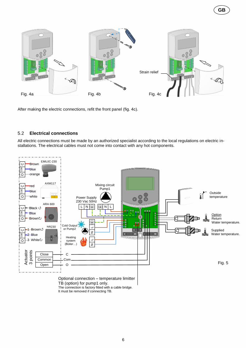
The ClimaticControl-HC can be installed directly on a solid base (e.g. a wall). For this purpose the front panel of the ClimaticControl-HC must be removed (fig. 4a) and the back section should be fastened using appropriate screws and pins (these are not included in the scope of supply) (fig 4b) Fix the climatic control HC on a plane surface (wall…) If the ClimaticControl-HC has been factory fitted with cables for connecting to a pump, valve drive, temperature limiter, sensors etc., take care not to damage or crack the cables during the installation. Furthermore these cables should not subjected to any tensile stress during installation. The cables will be fixed by means of the device for strain relief at the ClimaticControl-HC.
If the ClimaticControl-HC is delivered together with a hydraulic control unit (for example FRG or FlowBox) and if it is not attached to that unit by any installation plate or support, it should be installed next to that unit.
Pay attention to the correct connection of the cables if the ClimaticControl-HC is not installed directly on a hydraulic control unit but at some other place for the reason of better access. Refer to the directions about this in section 5.2 Electric connections.
1
2
3
4
5
6
7
8 9
10
11
12
13
a b c
Details Pos. 6
6
Fig.2
1: Operating modes 2: Keyboard is locked 3: Service Installation Menu 4: Manual operation / program override active
(display of temperature offset) 5: a) display temperature (°C / °F)
b) display time (12 h / 24 h)6: Type of temperature displayed
a) Water temperatureb) Outside temperaturec) Room temperature (if RF room thermostat con-nected)
7: Program graphic of the current day Comfort temperature Reduced temperature
8: Pump indicator 9: Demand indication
Heating / Cooling / Humidity function 10: Current day of the week (1 = Monday; 7 = Sunday) 11: RF reception indicator (optional). 12: a) Symbol temperature indication in °C / °F
b) Symbol AM / PM if 12 h mode13: a) Outside temperature (°C / °F)
b) Time (12 h / 24 h)14: Mixing valve activity indicator
Valve actuator is opening Valve actuator is closing
Fig.3
160,
mm
86 mm 47 mm
OK
14
Dimensions
6
GB
After making the electric connections, refit the front panel (fig. 4с).
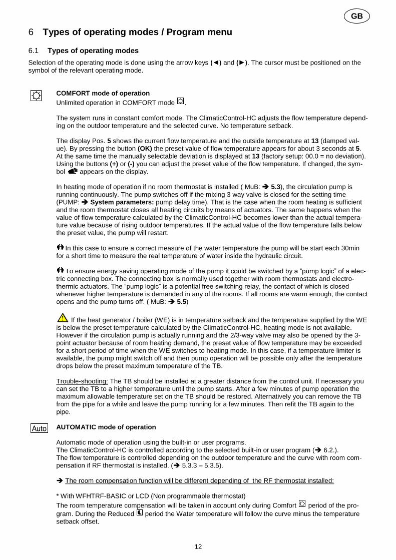
5.2 Electrical connections
All electric connections must be made by an authorized specialist according to the local regulations on electric in-stallations. The electrical cables must not come into contact with any hot components.
Fig. 5
Supplied Water temperature.
Mixing circuit Pump1
Outside temperature
L
N
Actu
ato
r
3 p
oin
ts
blue
white
red AXM117
Brown
NR230
Blue
Black
OC
OM
C
OC
OM
C
OC
OM
C 1 Brown
2 Blue
3 White
C
Optional connection – temperature limitter TB (option) for pump1 only. The connection is factory fitted with a cable bridge. It must be removed if connecting TB.
Com
O
Close
Common
Open
L N N L
Power Supply 230 Vac 50Hz
L
N
Cold Output or Pump2
Heating system
(Boiler…)
Option Return Water temperature.
ARA 600
blue
orange
Brown EMUJC-230
OC
OM C
OK
Fig. 4b
OK OK
Fig. 4c
Strain relief
Fig. 4a

7
GB
5.3 Room Temperature – Direct Plug In
As an option you can plug in a room thermostat to the ClimaticControl-HC. Direct plug in of a room thermostat op-timizes the operational time of the circulation pump and even the supply flow temperature depending on the condi-tions in the main room.
5.3.1 Mixed circuit (Water Floor), standard room thermostat, wired type
If a wired type of a standard room thermostat is plugged in and the preset room temperature is reached in the room, the under floor circulation pump switches off after pump delay time. (PUMP: System parame-ters: pump delay time)
5.3.2 Direct circuit (Panel Heater), standard room thermostat, wired type
If a second circulation pump is installed and managed by the ClimaticControl-HC (Inst: System param-eters: installation type, “2P.x”), you can install a second wired room thermostat to manage the working of the high temperature pump. This pump will work in the following way: If the preset room temerature is reached in the room the High water temperature circulation pump switches off after pump delay time. (PUMP: System parameters: pump delay time)
Fig. 7
4 4 2 1
In1
In2
4
< °C
2
In1
In2
42
WFHT-BASIC WFHT-LCD MILUX xxx
L
N
TH Output
Fig. 6
WFHT-BASIC WFHT-LCD MILUX xxx
4 4 2 1
In1
In2
4
< °C
2
In1
In2
42
L
N
TH Output

8
GB
5.3.3 Wireless room thermostat (Water Floor thermostat “trF1”)
With WFHT-RF (BASIC, LCD or MILUX)
If a radio frequency room thermostat is plugged in, the flow temperature calculated on the basis of outdoor temperature and the curve (= flow temperature preset value) is optimized depending on the main room tempera-ture.
The offset value is calculated in the following way:
Adjustment = preset value of supplied temperature + (room temperature - actual value) х compen-sation offset (Compensation offset: System parameters: “tr1o” Flow temperature offset for “trF1”)
Example 1: preset calculated value of flow temp. = 35 °C; room temperature: preset value = 21 °C, actual value = 19 °C; offset (tr1o) = 1,5 Estimation 1: 35 °C + (21 °C – 19 °C) × 1,5K =>> flow temperature increased by 3,0K to 38 °C
Example 2: preset value of flow temperature = 35 °C; room temperature: preset value = 21 °C, actual value = 22 °C; offset (tr1o) = 1,5 Estimation 2: 35 °C + (21 °C – 22 °C) × 1,5K =>> flow temperature decreased by 1,5K to 33,5 °C
The pump will be switched off when room temperature will be 1°C upper the setting temperature of the thermostat.
5.3.4 Wireless room Hygrostat (Water Floor thermostat “trF1”)
If a radio frequency room Hygrostat is plugged in, the flow temperature calculated on the basis of outdoor temperature and the curve (= flow temperature preset value) is optimized depending on the main room temperature. (See the previous part for more explanation)
The working mode (Heating or Cooling) of the installation could be managed by the end user directly on the room hygrostat. (See the MILUX humidity leaflet for more explanation)
The residual humidity will be supervised by the MILUX-RF hygrostat in the house. If humidity is detected the “Wcal“ temperature will be increased by step of 0.1°C/minute to avoid a too cold water on the hydraulic circuit and risk of condensation in the house.
5.3.5 Wireless RF room thermostat (High temperature circuit thermostat “trF2”)
If a second circulation pump is installed and managed by the ClimaticControl-HC (Inst: System param-eters: installation type, “2P.x”), you can install a second radio frequency room thermostat to supervise the working of the high temperature pump. This pump will work in the following way: If the preset room temerature is reached the High water temperature circulation pump switches off after pump delay time. (PUMP: System parameters: pump delay time)
Note: Only a standard room thermostat could be installed on the second circuit.
Ex: WFHT-RF (BASIC, LCD or MILUX).
WFHT-RF BASIC
WFHT-RF LCD
Only RF thermostats from the WFHT-RF series or the MILUX-RF series can be used with an active antenna 433,92. The MILUX-RF Hygrostat can be used only with the 433,92Mhz frequency
fig.8
MILUX-RF-xxx
RF thermostat initialization to the Controller: SYSTEM PARAMETERS MENU, section
RADIO-CONFIGURATION with RF room thermostat
MILUX-RF-Hygrostat

9
GB
5.4 Wireless RF outside sensor (Inst: System parameters: Input, “OUSE”).
As an option you can plug in a wireless RF outside sensor room thermostat to the ClimaticControl-HC. This solu-tion is very interesting in rehabilitation, to avoid wires trough the wall, in a building management with several CC-HC, in this case only one outside sensor can be installed to manage all the building.
Radio alarm: RF supervising function.
If the ClimaticControl-HC is installed with RF thermostat(s) and there is no radio signal received during more than 2
hours, a display alarm will be activated,the backlight and the small RF antenna logo radio will blink.
1. To stop the alarm, maintain the (OK) button pressed for about 10 seconds. 2. Check the batteries of the RF thermostat(s) or outside RF sensor. Please replace them if exhaust-
ed. 3. Check the position in which the antenna was installed. It must be installed in vertical position.
Installation in or on a metal body can abate the power of radio transmission. Minimize the distance to the RF thermostat.
If radio alarm is displayed:
- Due to the wireless thermostat, the regulation will continue to work as an installation without thermostat (no com-pensation). - Due to the Wireless outside sensor, the regulation will continue to work with the last value received from the out-side sensor.
5.5 Inputs functions (In1 & In2)
If no wired thermostat is installed in the house, you will have the possibility to use the two available inputs of your ClimaticControl-HC for different functions (Inst: System parameters: Input, “In1 & In2”).
5.5.1 Input1
Inst: System parameters: Input, “HC” You could use the input 1 to connect the an external signal which give the Heating or Coling working mode of the installation (This signal could be done directly by a reversible input). Inst: System parameters: Input, “Aqu” 1/ You could use the input 1 to connect the an imersion thermostat witch schould be placed in a storage tank. In Heating mode this immersion thermostat will be use to switch off the circulation pump (Pump1) to avoid cold water circulation in the circuit if the storage tank is discharged. (This solution is generally use when solid wood burner is installed) 2/ You could also use this input to have a priority on domestic hot water. In this case the pump of the heating circuit will be stopped to keep the priority on the domestic hot water.
Note: - The heating output will stay activated even if the aquastat have stopped the circulation pump. - To avoid problem in cooling mode, if the storage tank is filled with cold water (by heat pump...) the aquastat function will be automatically desactivated.
WIRELESS OUTSIDE SENSOR
The wireless outside sensor can be used only with the 433,92Mhz frequency
fig.9
RF outside sensor initialization to the Controller: SYSTEM PARAMETERS MENU, section
(Inst: System parameters: “OUSE”)

10
GB
Inst: System parameters: Input, “C_b” In case of mutizone regulation “WFHC Master RF with or without Heat&Cool function” is installed you could use the input 1 to connect the pump relay output to swtich off the circulation pump1 in case of no water circulation demand is asked in the house.
Note: - The heating output will follow the circulation demand from the pump1.
5.5.2 Input2
Inst: System parameters: Input, “HC” You could use the input 2 to connect the an external signal which give the Heating or Coling working mode of the installation (This signal could be done directly by a reversible input).
“HC” is only available if Input1 is set on “no or Aqua” Inst: System parameters: Input, “Aqu” You could use the input 2 to connect the an immersion thermostat witch schould be placed in a storage tank. In Heating mode this immersion thermostat will be use to switch off the circulation pump to avoid cold water circulation in the circuit if the storage tank is discharged.
The immersion thermostat connected on the Input2 will manage the working of the main circula-tion pump (Mixed circuit) if the ClimaticControl-HC drive only one pump. In the installation with two circulations pumps, the immersion thermostat connected on the Input2 will manage the working of the 2
nd circulation pump (direct circuit).
Note: - The heating output will stay activated even if the aquastat have stopped the circulation pump. - To avoid problem in cooling mode, if the storage tank is filled with cold water (by heat pump...) the aquastat function will be automatically desactivated. Inst: System parameters: Input, “C_b” In case of mutizone regulation “WFHC Master RF with Heat&Cool function” is installed you could use the input 2 to connect the pump relay output to swtich off the circulation pump in case of no circulation demand is asked in the house.
The WFHC connecting box connected on the Input2 will manage the working of the main circula-tion pump (Mixed circuit) if the ClimaticControl-HC drive only one pump. In the installation with two circulations pumps, the WFHC connecting box connected on the Input2 will manage the working of the 2
nd circulation pump (direct circuit).
In1 In
2 4
Closed = Cooling Mode
2
C 1 2
> T °C
L L’
Heating &
Cooling signal Immersion
thermostat
Example 1: Reversible installation with circulation pump (UFH application). In1 Used to change the working mode of the installation, signal from Heat Pump (Inst: System parameters: Input, “HC”)
In2 used to stop the pump when D.H.W is in demand (Inst: System parameters: Input, “Aqu”)
Fig. 10
Attention: In case of the CLIMATICCONTROL-HC must be linked with the Heat pump (from the Heat /
Cool switch) Pay attention to check the compatibility of the electrical signal before connection. The inputs 1 or 2 (Inst: Parameter menu: In1, In2 “HC”) need a live signal “Phase L” to works
in cooling mode.

11
GB
In1 In
2 4
2
C 1 2
> T °C Aquastat
(storage tank temperature supervising)
Example 2: Under floor heating installation with multizones connecting boxes. In1 used to stop the pump when no heat demand is asked in the house. (Inst: Parameters menu: In1, “C_b”)
In2 used to stop the pump when the storage tank is empty (Inst: Parameters menu: In2, “Aqu”)
Fig. 11
WFHC
Pump signal
closed = pump On
---------
In1 In
2 4
2
C 1 2
> T °C In2 :
Immersion thermostat Use to stop the pump2
Example 2: Installation with 2 circulation pumps (Under floor heating and panel heater). In1 used to stop the pump when the heat storage is empty (Inst: Parameters menu: In1, “Aqu”)
In2 used to stop the pump when the heat storage is empty (Inst: Parameters menu: In2, “Aqu”)
Fig. 12
C 1 2
> T °C In1:
Immersion thermostat Use to stop the pump1
12
GB
6 Types of operating modes / Program menu 6.1 Types of operating modes
Selection of the operating mode is done using the arrow keys (◄) and (►). The cursor must be positioned on the symbol of the relevant operating mode.
COMFORT mode of operation
Unlimited operation in COMFORT mode . The system runs in constant comfort mode. The ClimaticControl-HC adjusts the flow temperature depend-ing on the outdoor temperature and the selected curve. No temperature setback. The display Pos. 5 shows the current flow temperature and the outside temperature at 13 (damped val-ue). By pressing the button (OK) the preset value of flow temperature appears for about 3 seconds at 5. At the same time the manually selectable deviation is displayed at 13 (factory setup: 00.0 = no deviation). Using the buttons (+) or (-) you can adjust the preset value of the flow temperature. If changed, the sym-bol appears on the display. In heating mode of operation if no room thermostat is installed ( MuB: 5.3), the circulation pump is running continuously. The pump switches off if the mixing 3 way valve is closed for the setting time (PUMP: System parameters: pump delay time). That is the case when the room heating is sufficient and the room thermostat closes all heating circuits by means of actuators. The same happens when the value of flow temperature calculated by the ClimaticControl-HC becomes lower than the actual tempera-ture value because of rising outdoor temperatures. If the actual value of the flow temperature falls below the preset value, the pump will restart.
In this case to ensure a correct measure of the water temperature the pump will be start each 30min for a short time to measure the real temperature of water inside the hydraulic circuit.
To ensure energy saving operating mode of the pump it could be switched by a “pump logic” of a elec-tric connecting box. The connecting box is normally used together with room thermostats and electro-thermic actuators. The “pump logic” is a potential free switching relay, the contact of which is closed whenever higher temperature is demanded in any of the rooms. If all rooms are warm enough, the contact opens and the pump turns off. ( MuB: 5.5)
If the heat generator / boiler (WE) is in temperature setback and the temperature supplied by the WE is below the preset temperature calculated by the ClimaticControl-HC, heating mode is not available. However if the circulation pump is actually running and the 2/3-way valve may also be opened by the 3-point actuator because of room heating demand, the preset value of flow temperature may be exceeded for a short period of time when the WE switches to heating mode. In this case, if a temperature limiter is available, the pump might switch off and then pump operation will be possible only after the temperature drops below the preset maximum temperature of the TB. Trouble-shooting: The TB should be installed at a greater distance from the control unit. If necessary you can set the TB to a higher temperature until the pump starts. After a few minutes of pump operation the maximum allowable temperature set on the TB should be restored. Alternatively you can remove the TB from the pipe for a while and leave the pump running for a few minutes. Then refit the TB again to the pipe.
AUTOMATIC mode of operation Automatic mode of operation using the built-in or user programs. The ClimaticControl-HC is controlled according to the selected built-in or user program ( 6.2.). The flow temperature is controlled depending on the outdoor temperature and the curve with room com-pensation if RF thermostat is installed. ( 5.3.3 – 5.3.5). The room compensation function will be different depending of the RF thermostat installed: * With WFHTRF-BASIC or LCD (Non programmable thermostat)
The room temperature compensation will be taken in account only during Comfort period of the pro-
gram. During the Reduced period the Water temperature will follow the curve minus the temperature setback offset.

13
GB
* With MILUX RF (Programmable thermostat)
The room temperature compensation will be taken in account during Comfort and Reduced period of the program. In this case the program of the MILUX RF should be the same of the water program ad-justed on the CC-HC to have the best optimising energy consumption (the water temperature will be re-
duced due to the CC-HC program (in ) and by the setting temperature reduced also in the room due to the MILUX RF program. * With MILUX-RF HYGROSTAT (Programmable Heat and Cool thermostat with Humidity supervising) The program will be now done on the MILUX-RF HYGROSTAT (Program made on Zone1 see the user guide of the MILUX-RF HYGROSTAT for more explanation).
The room temperature compensation will be taken in account during Comfort and Reduced period of the MILUX-RF HYGROSTAT program. The Comfort and Reduced manual offsets added or subtracted to the calculated water temperature will be
always adjusted on the both working mode of the CC-HC ( 0.00°C & -10.0°C by default). For the operation of the circulation pump please refer to the section of COMFORT mode of operation.
REDUCED TEMPERATURE mode of operation
Unlimited operation in REDUCED TEMPERATURE mode . This is a constant mode of operation of the system. The ClimaticControl-HC adjusts the flow temperature continuously on the basis of outdoor temperature and the selected curve and substracting the value of temperature setback (factory setting -10.0 К in Heating mode & +3.0 К in Cooling mode). The display indicates the current flow temperature at 5 and the outside temperature at 13. By pressing the button (OK) the preset value for the supply flow temperature reduced by the setback in temperature is displayed at 5 for 3 seconds. Simultaneously the reducing difference appears in 13 (without deviation = -10.0). It can be changed by the buttons (+) or (-). For the operation of the circulation pump please refer to the section of COMFORT mode of operation. See the previous part for more explanation concerning the room compensation function when RF thermostat is installed.
ABSENCE/VACATION mode of operation
Time-limited operation of REDUCED TEMPERTURE mode . Duration can be set between 1 and 24 hours and up to a maximum of 44 days. When this period is ex-
pired the ClimaticControl-HC switches back to operating mode . By means of the arrow keys (◄) the cursor is first moved to . Then appears on the display at 13. The duration of absence can be changed using buttons (+) or (-).
Example: = 1 hour; = 1 day
Both symbols and start blinking. The remaining time is displayed at 13.
To discontinue this mode of operation before time you have to set the remaining time at 13 to using the (-) key.
STOP mode This mode is used to switch off the system. The device switches off the system. The ClimaticControl-HC software version is indicated on the display for about 3 seconds and then switches off (no indications). By pressing any of the keys the ClimaticControl-HC can be switched on.
REMARK: When the ClimaticControl-HC is in STOP mode, In Heating mode only an Anti-freeze function can restart heat relay and circulation pump to maintain the water temperature above 10°C.

14
GB
Heat & Cool Mode Use this mode to change the working mode of your installation, Heating or cooling mode.
This mode will be only displayed if: - The CC-HC is configured to manage a reversible installation (Inst: Parameters menu: Type, “Rev”) - No MILUX-RF HYGROSTAT is installed ( 5.3.4) and configured to manage the Heat and Cool mode. - No CC-HC inputs (In1 or In2) have chosen for a H_C signal input. ( 5.5)
Carfull: IF Heat pump or other system is used and not linked with the ClimaticControl-HC, pay attention to change the working mode on it before change on the ClimaticControl-HC. Because in this case the regulation will not work in the correct way.
TIME AND DATE – setting In this menu you can set the actual time and date as well as the day of the week.
Using the cursor select first and then press the (OK) key.
By keys (+) or (-) set the minutes; confirm by pressing (OK).
By keys (+) or (-) set the hour; confirm by pressing (OK)
By keys (+) or (-) set the day of the week; press (OK) to confirm.
(1 = Monday; 7 = Sunday)
6.2 Program Mode
This mode will be only displayed if no MILUX-RF Hygrostat is installed ( 5.3.4)
PROGRAM menu In this menu you choose the program of the Controller (duration of the periods for operation in reduced
temperature and heating mode), which is to be followed in operating mode . You can choose between factory set programs from P1 to P9 ( 6.2.1.) and one of the user’s programs from U1 to U4.
First you select with the help of the cursor. The indication appears at 5. Press the (OK) key and the
indication starts blinking. By the keys (+) or (-) now you can select the program you need and confirm it by pressing (OK). User-defined Programs (U1 – U4)
If you choose one of the user programs from U1 to U4, you can program the REDUCED temperature and NORMAL heating times directly. Proceed as follows:
At 13 the time indication blinks and day 1 is highlighted, while at 7 the time cursor blinks at 0 h on the sym-bol (heating mode). Pressing the (-) key you can move the time cursor to the symbol (REDUCED tem-perature mode). Then the time cursor jumps to the next hour. Thus COMFORT and REDUCED tempera-ture cycles are selected using the (+) and (-) keys. Using arrow keys (◄) and (►) you can select the time in the same manner. When day 1 programming is completed the time cursor switches automatically to 0:00h of day 2. Thereby
Day of the week.
Cursor time.
The key (+) allow you to choose a COMFORT period at the blinking cursor time. The key (+) allow you to choose a REDUCED period at the blinking cursor time.

15
GB
the programmed values for day 1 are stored. Programming other days is done using identical procedure moving the cursor by pressing (►). When you switch over to programming the next day the program for the previous day is saved. On completing the programming of the last day 7, the indication first switches to the
program menu , and in about 15 seconds back to . If during programming no inputs are made within 20 seconds, indication switches first to the program menu
, and in another 15 seconds it returns to . The inputs were not stored. Factory / built-in programs (P1 – P9)
If you select any of the factory programs from P1 to P9, you confirm it by pressing the key (ОК). Then pressing the arrow key (◄) scroll back to the menu for selecting an operation mode (if the arrow key is not
pressed in about 15 seconds the display turns back to operating mode ).
6.2.1 Factory set COMFORT & REDUCED temperature times in programs P1 - P9
P1: Morning, Evening & Week-end P6: Morning, Afternoon & Week-end P2: Morning, Midday, Evening & Week-end P7: 7h - 19h (Office) P3: Day & Week-end P8: 8h – 19h , Saturday (Shop) P4: Evening & Week-end P9: Week-end (Secondary House) P5: Morning, Evening (bathroom)
The ClimaticControl-HC program operates only in mode according to the selected COMFORT and RE-DUCED temperature periods.

16
GB
7 System Parameter Menu 7.1 System parameters setting
This menu is used to set the most important parameters for the operation of the system.
To access this menu keep the (OK) key pressed for 10 seconds (in Comfort, Auto, Reduced modes).
The display shows as well as the preset curve (for example ).
Parameters are selected by pressing the (◄) or (►) keys.
To change the parameters press (ОК) and using (+) or (-) change them.
To leave the menu goes to the parameter “End” and press the (OK) key.
SYSTEM PARAMETERS
Values Parameters description Factory setting
Alternative setting
User setting
_ _ _ Type 0
Type of installation Following your choice the list of pa-rameter will be different. Ex: The Cooling “curve” parameter will be not displayed if you choose “Hot” installation.
Hot Cld, rEv Hot For Heating installation only
CLd For Cooling installation only
rEv For reversible installation
Heating parameters
1
Heating curve value (see fig. 7) supplied water T° = curve(outside T°) 0.7 0.1 to 5
2
Maximum value of flow temperature in Heating mode 45 °C (Lo+5°C) – 100 °C
3
Minimum value of flow temperature in Heating mode 10 °C 1 – (Hi-1°C)
Cooling parameters
1
Cooling curve value (see fig. 7) supplied water T° = curve(outside T°) 0.4 0.1 to 5
2
Maximum value of flow temperature in Cooling mode 30 °C (Lo+5°C) – 100 °C
3
Minimum value of flow temperature in Cooling mode 15 °C 1 – (Hi-1°C)
_ _ _ Inst 4
Configuration of the hydraulic installa-tion
Act,
Act: installation with actuators The “Cold output” will manage a 3 way On/Off valve to choose Heating or cooling input. The “Heat output” will manage the Boiler.
See hydraulic
example section ( 10)
SEP: Installation with separate system (Boiler and chillers) One output for each element will be available.
SEP
The two following parameters are specially made for WATTMIX regula-

17
GB
tion or all others applications with 2 pumps circuits, The second pump will follow the 2
nd wired thermostat, and
will be wired on the “Cold output”.
2P.1: Panel Heaters + water floor heating and cooling system
2P.1 The second pump for
direct temperature circuit (panel heater)
will be stopped in cooling mode.
No cold water in panel heater!
2P.2: Fan coil units and Water Floor Heating and Cooling system
2P.2 The second pump is used to control a fan
coil circuit.
_ _ _ th 5
Thermostat selection menu:
No: Installation without thermostat Yes: Wired thermostat(s) is installed. rF: Wireless RF thermostat(s) is in-stalled.
No No, Yes, rF
The following parameter is only available if “th” parameter is set to “Yes”
_ _ _ thty 6
Wired thermostat type selection:
Std: Standard Heat only thermostat rEv: Reversible Heat&Cool thermostat
Std Std, rEv
The following parameter is only available “th” parameter is set to “Yes” or “no” and if water sensor is mounted on the return pipe of the hydraulic circuit.
_ _._ bGAP 7
bGAP Boost function The incoming water temperature will be increased by +20%* if the return temperature is less than calculated water temperature minus bGAP set-ting. Wret < Wcal – bGAP => WCal +20%* Press on the (OK) to view the instan-taneous value of the return sensor. Remark: if no water return sensor is wired then this boost function is bypassed. *Remark2: in Cold mode “-20%”
10.0°C 1 to 20°C
The following parameter is only available if “th” parameter is set to “rF”
_ _ _ trF1 8
RADIO-CONFIGURATION with RF thermostat for room temperature (trF1) 1. Press the (OK) key. Using the (+) or (-) keys to set the Controller into rf init mode.
„INI thrF“ appears on the display. 2. Set the RF thermostat into rf init mode ( MuB). 3. If successful rf initialisation the RF thermostat sends a radio signal to the Controller.
The actual value of room temperature appears flashing on the display instead of ”INI”. 4. The process is completed by pressing the (OK) key of the Controller. 5. Exit the rf init mode of the RF thermostat. ( MuB). Selecting „no thrF“ disconnects the RF thermostat from the Controller and discontinues the room temperature plug-in function respectively.

18
GB
Connection of wireless room thermostat is only possible using appropriate device.
The following parameter is only available if “th” parameter is set to “rF” and if “inst” parameter is set to “2P.1” or “2P.2” (2 pumps mode)
_ _ _ trF2 9
RADIO-CONFIGURATION with RF thermostat for WATTMIX system (trF2) (2 pumps system with panel heaters or fan coils) same radio configuration sequence as parameter “trF1” just above
The following parameter is only available if “th” parameter is set to “rF”
_ _ _ tr1o 10
Flow temperature offset for RF thermostat for room temperature (trF1) See the working explanation ( 5.3.3).
3.0°C 0.1 to 9.9C
_ _ _ in1 11
Wired Input1 selection: ( 5.5.1).
th1: the wired room thermostat should be
wired on Input1 because “th” parameter is set
to “YES”) no: Input1 not used (nothing wired)
no
th1 un-adjustable
no, Aqu,
HC or C_b
Aqu: A water Aquastat contact is wired on Input1. If over temperature is reached (contact open) then Pump1 circulator is stopped and the mixing valve is closed.
HC: A Heat/Cool switching signal is wired on In-put1 to manage the working mode of the in-stallation. (contact between point 2 and In1 or phase signal on In1) Heating = no signal (open circuit ) Cooling = Phase signal (closed circuit)
The HC signal
could be done by a heat pump.
Check the electri-cal compatibility
before connection
C_b: A pump signal from a connecting box is wired on Input1 to manage the working of the pump1. (contact between point 2 and In1 or phase signal on In1) Pump ON = Phase signal (closed circuit) Pump OFF = no signal (open circuit )
_ _ _ in2 12
Wired Input2 selection: ( 5.5.2). th2: the wired thermostat for second pump system should be wired on Input2 (because “th” parameter is set to “YES” and “inst” is set to “2P.x”) no: Input2 not used (nothing wired)
no
th2 not-adjustable
no, Aqu,
HC or C_b
Aqu: A water Aquastat is wired on Input2. If over temperature is reached (contact open) then: - if “inst”=”Act or SEP”, Pump1 circulation is stopped & mixing valve is closed. - if “inst”=”2P.x”, direct circuit Pump2 circula-

19
GB
tion is stopped.
HC: A Heat/Cool switching signal is wired on In-put1 to manage the working mode of the in-stallation. (contact between point 2 and In1 or phase signal on In1) Heating = no signal (open circuit ) Cooling = Phase signal (closed circuit).
The HC signal
could be done by a heat pump.
Check the electri-cal compatibility
before connection
C_b: A pump signal from a connecting box is wired on Input1 to manage the working of the pump1. (contact between point 2 and In1 or phase signal on In1) Heating = no signal (open circuit ) Cooling = Phase signal (closed circuit). - if “inst”=”Act or SEP”, water floor Pump1 circulation is stopped & mixing valve is closed. - if “inst”=”2P.x”, direct circuit Pump2 circula-tion is stopped.
_ _ _ OUSE 13
Outside sensor menu: Yes: Wired outside sensor is installed. No: Installation without outside sensor The regulation will work like a “thermostat” with a adjustable “Wcal” temperature injected on the circuit. rF: Wireless RF outside sensor is installed.
Yes No, rF
The following parameter is only available if no outside sensor is installed and the “OUSE” parameter is set to “no”.
_ _ _ OU t 14
Outside temperature: This menu is used to fix the outside tempera-ture to have the desired calculated water temperature in accordance to the curves. Example: Ou t = 0°C, Curv = 1 Wcal => 40°C You could adjust with more accuracy the “Wcal” temperature since the main screen with the “Comfort” and “Reduced” offset.
00.0°C -49.0°C to
50.0°C
The following parameter is only available if “OUSE” parameter is set to “rF”
14
RADIO-CONFIGURATION with RF sensor for outdoor temperature Same radio configuration sequence as parameter 8 “trF1” above.
16
Temperature indication in °C or °F °C °F
17
Time indication mode 24 hours or 12 hours
24H 12H Am/Pm
18
Side-track protection YES (ac-
tive) NO (inactive)
When YES is selected the pump and the auxiliary actuator are activated at midday 12 hrs, if they haven’t been active for a period of 24 hours. (12h00: Pump ON 1min, 12h01: Open actuator 2min, 12:03: Close actuator 2min)

20
GB
The following parameter “Pump” is only used when no RF thermostats are installed and if no inputs (In1 & In2) are used for connecting box (C_b) and aquastat (Aqu) function.
_ _ _ PUMP 19
Pump delay time: Time duration to switch off the pump after the stop demand from the wired thermostat or after complete close of the 3 way mixing valve. This function is also interesting to avoid permanent ON/OFF cycle of the pump when “PWM” thermostat is installed.
030
For best use the duration should be => 2xPWM cycle of the thermo-
stat
001 to 060, and above “- - -“
= infinite delay, the pump will be ON
all the time
20
Manual mode (or test function) for valve drive respectively 2/3-way valve By pressing the (+) key the valve drive opens. The display shows “OPEN“ and . By pressing the (–) key the valve drive closes. The display shows “CLOSE“ and . By pressing the (◄) or (►) key current position of the valve drive is kept. Displays “STOP“
There is a actuator security anti-short delay: when switching from “OPEN“ to “CLOSE“ or “CLOSE“ to “OPEN“, the actuator will be stopped during 15s
_ _ _ PrH 21
Floor / screed preheating program.
0 dry 7 dry
The program is started by selecting „7 dry“ and runs automatically. For a period of 3 days the flow temperature is kept at 25 °C (days 7, 6, 5). For next 4 days the flow temperature is maintained at its preset maximum value (days 4, 3, 2, 1). The number of the days until the end of the heating program is displayed.
22
Floor / screed dehumidifi-cation program
0 PrH
Default value after “ON” => 13 Days
7 to 60 days
The program is started by selecting the desired numbers of days and runs automatically. Example: 13 days selected: (3days rise + 7days at Hi + 3days decrease) For a period of 3 days the flow temperature will be increased up to the “Hi” value, then the tempera-ture will be kept at the “Hi” value during 7 days. For the last 3 days the temperature will be decreased up to the “Lo” value. Example2: 7 days selected: (3days rise + 1day at Hi + 3days decrease)
The number of the days left until the end of the fllor dehumidification program is displayed.
23
Reset function By keeping the (OK) key pressed for about 5 seconds all system parameters, time and day
of the week as well as user programs in are reset to the factory setting. Established
radio configuration to rf thermostats, if any, is also erased. The cursor moves to .
End 24
Press on the (OK) key to exit the installer menu and come back to the main menu in mode.

21
GB
7.2 Heating & Cooling curves
7.3 Corresponding value for sensors.
To be checked with an ohmmeter with sensor unplugged.
Temperature (°C) Resistance value (Ohm) Temperature (°C) Resistance value (Ohm)
-20°C ~94 k 40°C ~5,3 k
-10°C ~54 k 50°C ~3,6 k
0°C ~32 k 60°C ~2,5 k
10°C ~20 k 70°C ~1,8 k
20°C ~12,5 k 80°C ~1,3 k
30°C ~8 k
8 Technical Data / Materials
Measured temperature accuracy: 0,1 °C Operating temperature: 0 - 50 °C Flow temperature control range: 0 - 100 °C Regulation characteristics: Non-linear logarithmic PID control
Intelligent 3-point control (automatic detection of operating point) Electrical protection: Class II – IP 30 Supply voltage: 230 V (±10%), 50 Hz Outputs: pump: Cold: Heat: 3-point control:
5 A / 250 V relay (L, N, PE) 5 A / 250 V relay (L, N, PE) 5 A / 250 V relay (L, N, PE) 2 TRIACS => 75 W max. "Maximum opening time 240 seconds; Suitable for actuators that have an opening time below 240 Seconds”
Sensors: outside temperature: supplied temperature:
return temperature:
CTN 10 K at 25 °C (class II, IP55)
CTN 10 K at 25 °C (class I, IP68, no coupling)
CTN 10 K at 25 °C (class I, IP68, no supply) Software version: _.__ (displayed when switched off – STOP mode).
Outside temperature (°C)
Fig. 9

22
GB
9 TROUBLE-SHOOTING
X. TROUBLE
X.X Possible reason Elimination
1. The display shows
1.1 at 13 Disconnected outside temperature sensor
Check whether the connection of sensor cable is correct. Check the cable for damages. Replace the cable or the sensor, if necessary.
1.2 at 5 Disconnected flow temperature sensor
Check whether the connection of sensor cable is correct. Check the cable for damages. Replace the cable or the sensor, if necessary..
2. Incorrect flow temperature
2.1 Incorrect flow setting temperature The displayed calculated temperature is not in accordance with the regulation curve.
Check if no offset are adjusted ( 6.1). COMFORT and REDUCED temperature Offset.
2.2 Too high flow temperature due to incorrectly con-nected valve drive (reverse action)
Check the connection of the valve drive ( 5.2).
2.3 Too low flow temperature due to incorrectly con-nected valve drive (reverse action)
Check the connection of the valve drive ( 5.2).
2.4 Incorrect selected operation mode Select the correct mode of operation.
2.5 When ClimaticControl-HC operating in AUTO-MATIC mode: - incorrect programming of built-in or user pro-gram - incorrect setting of time / day of the week
- Check the factory program or the user program settings and pay attention to the correct setting of COMFORT and REDUCED temperature periods of operation.
- Check the setting of the time / day of the week.
3. The pumps or the valve drive does not work
3.1 Cable connections reversed. Check the electric connections ( 5.2).
3.2 Pump connected to temperature limiter. - Check the electric connection ( 5.2). - Check the maximum temperature setting of the TB. - Check the ambient temperature of the TB. If necessary,
change its position. - Check the TB operation. Replace it if necessary.
Remark:
Lock function
To prevent mistakes after installation, all critical parameters are not accessible any more after 4 hours power on. If you want to modify these parameters, you must unplug and plug in controller. No settings are lost when unplug-ging, or after a power failure. After 4 hours you can still change all the other parameters to optimize your system.
23
GB
10 Hydraulic example
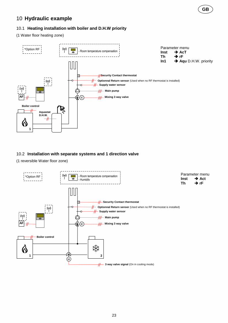
10.1 Heating installation with boiler and D.H.W priority
(1 Water floor heating zone)
10.2 Installation with separate systems and 1 direction valve
(1 reversible Water floor zone)
AF
Security Contact thermostat
1
M M
Parameter menu Inst AcT Th rF
In1 Aqu D.H.W. priority
Optionnal Return sensor (Used when no RF thermostat is installed) Supply water sensor
Main pump
Mixing 3 way valve
Boiler control
- Room temperature compensation
*Option RF
Aquastat
D.H.W.
AF
Security Contact thermostat
2 M
1
M M
Parameter menu Inst Act
Th rF
Optionnal Return sensor (Used when no RF thermostat is installed)
Supply water sensor
Main pump
Mixing 3 way valve
3 way valve signal (On in cooling mode)
Boiler control
- Room temperature compensation - Humidity
*Option RF

24
GB
10.3 Installation with separate systems
(1 reversible Water floor zone)
10.4 Installation with reversible Heat pump
(1 reversible Water floor zone and 1 panel heater circuit)
AF
Security Contact thermostat
2 1
M M
Optionnal Return sensor (Used when no RF thermostat is installed)
Supply water sensor
Main pump
Mixing 3 way valve
Water chillers signal Boiler control
Parameter menu Inst SEP
Th rF
- Room temperature compensation - Humidity
*Option RF
AF
Security Contact thermostat
1
M M
- Room temperature compensation - Humidity
Supply water sensor
WFH Main pump1
Mixing 3 way valve
HeatPump
signal
Parameter menu Inst 2P.1 Th rF In1 HC
In2 Aqu
Pannel heater
pump
- Room temperature
HP
Aquastat

25
GB
10.5 Installation with reversible Heat pump
(1 reversible Water floor zone and 1 Fan coil circuit)
10.6 Complete under floor Heating and Cooling Installation
(UFH Multizone)
AF
Security Contact thermostat
1
M M
- Room temperature compensation - Humidity
Supply water sensor
WFH Main pump1
Mixing 3 way valve
HeatPump
signal
Parameter menu Inst 2P.2 Th rF In1 Aqu In2 Aqu
Pannel heater
pump
- Room temperature
HP
Aquastat
ST
Aquastat
M
AF
TB
RT3 RT2 RT1
Main room hygrostat to manage the heat&cool change over of the installa-tion and program for all the house.
M
A A + B
A
A
B
1 2
M
M
RF Master Heat&Cool
A
HP
Parameter menu Inst Act when H.P Inst SEP Th rF In1 Aqu when H.P
ST
Pump signal
Aquastat
Separate systems or Reversible heat pump

26
GB

27
F
GUIDE D’INSTALLATION ET D’UTILISATION ClimaticControl-HC contrôleur de chauffage et de climatisation
IMPORTANT! Avant de commencer les travaux, le monteur doit lire, comprendre et observer les présentes instructions de montage et de service. Seul un spécialiste en la matière est autorisé à effectuer le montage, le réglage et la maintenance du ClimaticCon-trol-HC. Un monteur en formation ne peut réaliser de travaux sur l'appareil que sous la surveillance d'un expert. La responsabilité du fabricant conformément aux dispositions légales s'applique uniquement dans le cas du respect des conditions précitées. Veuillez observer l'ensemble des instructions de montage et de service lors de l'utilisation du ClimaticControl-HC. Toute utilisation autre n'est pas conforme. Le fabricant ne répond pas des dommages occasionnés par une utilisation abusive du ClimaticControl-HC. Pour des raisons de sécurité, aucune transformation ou modification n'est admise. Seuls les ateliers de réparation désignés par le fabricant sont habilités à réparer le ClimaticControl-HC. Le contenu de la livraison de l'appareil varie selon le modèle et l'équipement. Cette notice d’installation fait partie intégrante du produit et doit être conserver. Sous réserve de modifications techniques !
Table des Matières
1 Application .............................................................................................................................................. 28 2 Références, Symboles and Abréviations ............................................................................................... 28 3 Consignes de sécurité ............................................................................................................................ 28 4 Afficheur ................................................................................................................................................. 29 5 Installation et raccordement électrique .................................................................................................. 29 5.1 Installation du ClimaticControl-HC ......................................................................................................... 29 5.2 Raccordements électriques .................................................................................................................... 30 5.3 Thermostat D’ambiance – Direct Plug In ............................................................................................... 31 5.3.1 Zone plancher « In1 » : température d’eau variable thermostat de type filaire...................................... 31 5.3.2 Zone radiateurs « In2 »: consigne de température d’eau fixe (Sans vanne mélangeuse) .................... 31 5.3.3 Circuit à vanne mélangeuse, thermostat d’ambiance RF “trF1” ............................................................ 32 5.3.4 Circuit à vanne mélangeuse, thermostat hygrostat d’ambiance RF “trF1” ............................................ 32 5.3.5 Circuit direct (sans vanne mélangeuse), thermostat d’ambiance RF “trF2” .......................................... 32 5.4 Wireless RF outside sensor (Inst: System parameters: Input, “OUSE”). .......................................... 33 5.5 Fonctions des entrées logique (In1 & In2) ............................................................................................. 33 5.5.1 Entrée 1 “In1” ......................................................................................................................................... 33 5.5.2 Entrée 2 “In2” ......................................................................................................................................... 34 6 Description des modes de fonctionnements .......................................................................................... 36 6.1 Types de fonctionnement ....................................................................................................................... 36 6.2 Menus de programmation ...................................................................................................................... 38 6.2.1 Description des programmes usine P1 à P9 .......................................................................................... 40 7 Menu Installation et Annexes ................................................................................................................. 41 7.1 Paramètres d’installation ........................................................................................................................ 41 7.2 Courbe de régulation .............................................................................................................................. 46 7.3 Valeurs de référence ohmique pour les sondes de température. .......................................................... 46 8 Caractéristiques Techniques .................................................................................................................. 46 9 DEFAUTS ET SOLUTIONS ................................................................................................................... 47 10 Example d’installation hydraulique ......................................................................................................... 49 10.1 Installation chauffage avec Chaudière et gestion priorité E.C.S ............................................................ 49 10.2 Installation avec P.A.C réversible ou élément séparés (avec 1 vanne de direction) ............................. 49 10.3 Installation avec élément séparés .......................................................................................................... 50 10.4 Installation avec P.A.C réversible .......................................................................................................... 50 10.5 Installation avec P.A.C réversible .......................................................................................................... 51 10.6 Installation avec P.A.C réversible ou élément séparés .......................................................................... 51

28
F
1 Application
Le ClimaticControl-HC est utilisé pour la régulation à température variable d’un système basse température (ex: plancher chauffant et rafraichissant, murs chauffants, Ventilo convecteur) ainsi qu’une régulation à con-signe fixe d’un système à haute température (radiateurs). La température de départ de la zone à consigne va-riable est régulée en fonction de la température extérieure grâce à une courbe de chauffe ajustable. La pente de la courbe sera dépendante des conditions extérieures et des émetteurs.
Grâce à ce ClimaticControl-HC, les réglages pourront être adaptés, pour des résidences, des appartements ou des bureaux. La régulation est munie d’une horloge de programmation hebdomadaire, avec 9 pré-programmes et 4 programmes utilisateur personnalisables.
Le ClimaticControl-HC est normalement utilisé en conjonction avec un système hydraulique (circulateur, vannes mélangeuses…)
Le ClimaticControl-HC a été étudié pour un fonctionnement dans un environnement sec. Il devra être installé dans un local technique.
Il est recommandé d’installer ce module selon les règles de l’art, tout en respectant les législations en vigueur.
2 Références, Symboles and Abréviations
Pour une meilleure compréhension du document, des références sont utilisées sous forme de symboles et d’abréviations qui sont décrites ci-dessous. Référence à un point du document FlH Plancher chauffant
Informations importantes FH Chauffage radiant (général)
Information sur la sécurité et sur les fonctions FRG Module de régulation (HCU)
Touche Ok (OK) HKV Collecteur
Touche de navigation Gauche (◄) Mut Notice d’utilisation
Touche de navigation Droite (►) TC Limiteur de température
Touche Plus (+) PMP Circulateur
Touche Moins (-) CH Chaudière / générateur
3 Consignes de sécurité
Veillez toujours à déconnecter l’alimentation avant le montage ou la manipulation ! Toute installation ou raccordement électrique sur le ClimaticControl-HC doit être réalisé dans des condi-tions de sécurité. Le ClimaticControl-HC devra être raccordé et manipulé par du personnel qualifié. Veuillez respecter les législations de sécurité en vigueur, en particulier les normes VDE 0100 / NF C15-100 (Normes d’installation ≤ 1000 VAC).
Le ClimaticControl-HC n’est pas étanche aux éclaboussures ou aux projections d’eau. Il doit donc être monté dans un endroit sec.
Prêter une attention particulière lors du câblage des sondes, n’interchangez jamais les connections des sondes avec les connections de puissances (230 VAC) ; ceci pourrait provoquer des dommages électriques, voire la des-truction des sondes ou de la régulation.

29
F
4 Afficheur
5 Installation et raccordement électrique
5.1 Installation du ClimaticControl-HC
Le ClimaticControl-HC peut être installé directement sur une base solide (par exemple un mur). Pour cela le capot du ClimaticControl-HC doit être retiré (fig. 4a) et la section arrière doit être fixée par un système de vis et chevilles (non fournies avec le support) (fig 4b) Fixer le climatic control HC sur une surface plane (mur…) Si le ClimaticControl-HC est équipé de câbles pour la connexion d’une pompe, d’une vanne, d’un limiteur de tem-pérature, sondes, etc, veuillez prendre garde à ne pas sectionner ou endommager les câbles de pompe, de la
vanne ou autres lors du montage. De plus veillez à ce que les câbles ne soient pas stressés ou tirés. Fixer les à
l’aide des serre câbles qui se trouve sur le ClimaticControl-HC. Si le ClimaticControl-HC est livré avec une unité de contrôle hydraulique (par exemple FRG ou FlowBox) et si il n'est pas attaché à cette unité par une plaque de montage ou un support, il doit être installé à côté de cette unité. Dans ce cas, prêtez une attention particulière à la position de la régulation (projection d’eau, …) Se référer au paragraphe 5.2 Raccordement électrique
1
2
3
4
5
6
7
8 9
10
11
12
13
a b c
Détails Pos. 6
6
Fig.2
1: Modes de fonctionnement 2: Clavier verrouillé 3: Menu installation 4: Décalage Manuel de la courbe de régulation
(La valeur de l’offset est affichée) 5: a) Température de départ (consigne ou mesurée)
b) Heure (12 h / 24 h) 6: Type de température affichée a) Température de départ
b) Température extérieure c) Température ambiante
7: Représentation graphique du programme de la journée.
Température de confort Température réduite.
8: Circulateur en fonctionnement 9: Mode de fonctionnement Chauffage / Rafraîchissement / Déshumidification 10: Jour courant (1 = Lundi; 7 = Dimanche) 11: Indication de réception RF 12: a) Type de degrés °C / °F b) Type d’heure AM / PM si mode 12H 13: a) Température extérieure ou offset
b) Heure (12 h / 24 h) 14: Vanne mélangeuse en mouvement
La vanne s’ouvre. La vanne se ferme.
Fig.3
160,
mm
86 mm 47 mm
OK
14

30
F
Après avoir fait les raccordements électriques, remonter le capot frontal (fig. 4c).
5.2 Raccordements électriques
Les raccordements électriques devront être réalisés par un installateur/électricien qualifié en accord avec les légi-slations en vigueur sur les installations électriques. Les câbles électriques ne doivent pas être en contact direct avec des éléments chauds.
Fig. 5
Sonde de départ.
Circuit mélangeur Circulateur1
Sonde extérieure
L
N
C
Option– thermostat de sécurité TB (circulateur1) En cas de montage d’un limiteur de température TC, enlever le pont qui est pré câblé en usine.
Com
L N N L
Alimentation 230Vac 50Hz
L
N
Sortie Froid ou
Circul.2
Chaudière
Option Sonde de retour
Van
ne
3 p
oin
ts
bleu blanc
rouge AXM117
Marron
NR230
Bleu Noir
O C
OM C
O
CO
M C
O
CO
M C
1 Marron 2 Bleu 3 Blanc
Fermeture Commun Ouverture
ARA 600
bleu orange
marron EMUJC-230
O C
OM C
marron
O
OK
Fig. 4b
OK OK
Fig. 4c
Serre-câbles
Fig. 4a 4a

31
F
5.3 Thermostat D’ambiance – Direct Plug In
Vous pouvez connecter un thermostat d’ambiance à votre régulation. Ce thermostat d’ambiance vous permettra d’optimiser la température ambiante dans la pièce où se trouve le thermostat. Cette optimisation se fera, soit par le contrôle du temps de fonctionnement du circulateur dans le cas d’un thermostat de type filaire, soit par le contrôle de la température de départ d’eau (correction de la courbe) dans le cas d’un thermostat de type RF.
5.3.1 Zone plancher « In1 » : température d’eau variable thermostat de type filaire
Avec un thermostat filaire l’optimisation de la température ambiante se fait par le controle du circulateur et de la vanne mélangeuse. Le circulateur et la vanne seront stoppés en cas de non demande du thermostat. L’arrêt se fera après la temporisation ajustée depuis le menu paramètre (PUMP: Menu paramètre : Temporisation de coupure)
5.3.2 Zone radiateurs « In2 »: consigne de température d’eau fixe (Sans vanne mélangeuse)
Le deuxième thermostat RF gère le fonctionnement du circulateur de la zone radiateur. Le circulateur sera arrêté en cas de non demande du thermostat. L’arrêt se fera après la temporisation ajustée depuis le menu paramètre (PUMP: Menu paramètre: Temporisation de coupure)
Fig. 7
WFHT-BASIC WFHT-LCD
4 4 2 1
In1 In
2 4
< °C
2
In1
In
2
4
2
MILUX (ou thermostat 2 fils)
L
Sortie TH N
Fig. 6
WFHT-BASIC WFHT-LCD MILUX
(ou thermostat 2 fils)
4 4 2 1
In1
In
2
4
< °C
2
In1
In
2
4
2
L
N
Sortie TH

32
F
5.3.3 Circuit à vanne mélangeuse, thermostat d’ambiance RF “trF1”
Dans le cas d’une installation avec un thermostat RF, c’est la température de départ d’eau (calculée par la courbe de régulation en fonction de la température extérieure) qui sera ajustée en fonction de la température ambiante dans la pièce. Cet ajustement est calculé de la manière suivante : Nouvelle temp. de départ = Valeur théorique de la temp. de départ “Wcal” + ((temp. de consigne – temp. ambiante) х offset) (offset: Menu paramètre ”tr1o” => valeur de l’offset ajouté pour le calcul de la nouvelle température) Exemple 1: Valeur théorique de la temp. de Départ = 35 °C; Consigne thermostat: = 21 °C,
Température ambiante = 19 °C; offset = 1,5 Estimation 1: 35 °C + ((21 °C – 19 °C) × 1,5) >> Température d’eau sera augmentée de 3,0K soit 38°C Exemple 2: Valeur théorique de la temp. de Départ = 35 °C; Consigne thermostat: = 21 °C,
Température ambiante = 22 °C; offset = 1,5 Estimation 2: 35 °C + ((21 °C – 22 °C) × 1,5) >> Température d’eau sera diminuée de 1,5K soit 33,5°C
Dans tous les cas la température d’eau sera diminuée au maximum de 1 x la valeur de l’offset au-delà, c’est le circulateur qui sera coupé. Il sera remis en route quand la température ambiante dans la pièce redescendra en dessous de (Température de consigne thermostat + 2°C).
5.3.4 Circuit à vanne mélangeuse, thermostat hygrostat d’ambiance RF “trF1”
Dans le cas d’une installation avec un thermostat hygrostat RF, c’est la température de départ d’eau (cal-culée par la courbe de régulation en fonction de la température extérieure) qui sera ajustée en fonction de la température ambiante dans la pièce. (Voir partie précédente pour plus d’explication):
Vous pourrez aussi gérer à distance depuis votre thermostat le mode de fonctionnement de votre installa-tion (Chauffage / rafraichissement). (Reportez-vous à la notice fournie avec le thermostat hygrostat pour plus d’explication).
L’humidité résiduelle dans la pièce sera supervisée de la manière suivante: Si le seuil d’humidité réglée sur le thermostat hygrostat est dépassé la température d’eau “Wcal” envoyée dans le circuit hydraulique (vanne mélangeuse) sera augmentée au rythme de 0.1°C/ minute jusqu’à que le taux d’humidité dans la pièce soit de nouveau correcte.
5.3.5 Circuit direct (sans vanne mélangeuse), thermostat d’ambiance RF “trF2”
Si un deuxième circulateur est installé et géré par la régulation (Inst: Menu paramètre: Type d’installation, “2P.x”), vous aurez la possibilité d’installer un deuxième thermostat RF afin de gérer le fonc-tionnement du deuxième circulateur. Le circulateur sera arrêté en cas de non demande du thermostat. L’arrêt se fera après la temporisation ajustée depuis le menu paramètre (PUMP: Menu paramètre: Temporisation de coupure des circulateurs)
Note: Seul un thermostat standard pourra être installé sur le deuxième circuit. Ex: WFHT-RF (BASIC, LCD or MILUX).
WFHT-RF BASIC
WFHT-RF LCD
fig.8
MILUX-xx-RF
Comment appairer un thermostat RF: Menu Paramètres => Thermostat rF => trF1 et trF2
Seuls les thermostats RF de nos gammes WFHT-RF, MILUX-RF peuvent être utilisés avec l’antenne active 433,92Mhz. Le MILUX Hygrostat RF sera uniquement compatible avec la fréquence 433,92Mhz.
MILUX-Hygrostat

33
F
5.4 Wireless RF outside sensor (Inst: System parameters: Input, “OUSE”).
Vous pouvez connecter une sonde extérieure RF (sans fil) à votre régulation. Cette option pourra s’avérer très intéressante dans le cas des rénovations (plus de perçage de mur extérieure, plus de fils…) ou bien encore dans les immeubles avec plusieurs appartement, dans la cas ou plusieurs régulations devront être installées. Dans ce cas-là une seule sonde externe pourra contrôler toutes les régulations.
Alarme Radio: Fonction de supervisassions Votre régulation est équipée d’un système de surveillance radio. Une alarme sera alors affichée si la régulation ne reçoit aucun signal du thermostat pendant 2 heures.
Le rétro éclairage ainsi que le pictogramme de réception radio seront clignotant pour attirer votre attention. Procédure à suivre en cas d’alarme radio :
1. Appuyer sur la touche (OK) pendant 10 s pour acquitter le défaut. 2. Vérifier les batteries du thermostat ou de la sonde extérieure et remplacer les si besoin. 3. Vérifier l’installation, tout d’abord le positionnement de l’antenne (une position verticale à une dis-
tance d’environ 50cm de toute partie métallique est généralement la plus adaptée).
En cas d’alarme : - Due à la perte d’un thermostat RF l’installation continuera de fonctionner comme une installation sans thermostat. - Due à la perte de communication avec la sonde extérieure RF l’installation continuera de fonctionner avec la dernière valeur reçue par la régulation (valeur affichée en “13” sur l’afficheur).
5.5 Fonctions des entrées logique (In1 & In2)
Si les entrées logiques ne sont pas assignées à des thermostats de type filaire, vous aurez la possibilité de les utilser pour les fonctions suivantes : (Inst: Menu paramètres: Entrées, “In1 & In2”).
5.5.1 Entrée 1 “In1”
Inst: Menu paramètres: In1, “HC” Vous avez la possibilité d’utiliser l’entrée 1 en tant qu’entrée de commutation de mode de fonctionnement (Chauffage / Rafraichissement). Ce signal pourrait être donné directement par une P.A.C. : dans ce cas, le basculement du mode chauffage ou rafraîchissement sur la PAC, basculera automatiquement le mode du ClimaticControl-HC.
Inst: Menu paramètres: In1, “Aqu” 1/ Dans le cas d’une installation avec réservoir de stockage (tampon) vous aurez la possibilité de connecter un thermostat à immersion qui sera placé à l’intérieur du réservoir. Il aura pour but de couper le circulateur (circuit à vanne mélangeuse) en cas d’épuisement du réservoir afin d’éviter une circulation d’eau froide dans le circuit. (il permettra aussi d’éviter un épuisement total du réservoir). Cette solution peut s’avérée interessante dans les installation avec chaudière à bois et réservoir tampon. 2/ Vous pourrez utilisé ette entrée pour donner une priorité à l’Eau Chaude Domestique (E.C.S), si l’aquastat dans le réservoir d’E.C.S s’ouvre alors le circulateur chauffage s’arr^tera pour permettre une chauffe plus rapide du réservoir E.C.S.
Sonde extérieure Radio fréquence
La sonde extérieure radio sera uniquement compatible avec la fréquence 433,92Mhz.
fig.9
Comment appairer une sonde RF: Menu Paramètres => OUSE _ RF

34
F
Note: - La sortie Chaudière restera activée en quand de déclenchement de l’aquastat (coupure du circulateur 1). - Afin d’éviter les éventuels problèmes de changement de consigne des aquastats en mode rafraichissement si le réservoir de stockage est chargé en eau froide, la fonction aquastat sera automatiquement ignorée par la régulation.
Inst: Menu paramètres: In1, “C_b” Dans le cas d’installation de chauffage par plancher chauffant ou réversible multi zones gérer par électrovannes thermique, par exemple avec nos systèmes de boite de connxions type ”WFHC” vous pourrez récupérer l’information de pompe afin de couper votre circulateur si aucune pièces est en demande de chauffe.
Note: - La sortie chaudière suivra alors la demande de circulation (Circulateur 1).
5.5.2 Entrée 2 “In2”
Inst: Menu paramètres: In2, “HC” Vous avez la possibilité d’utiliser l’entrée 2 en tant qu’entrée de commutation de mode de fonctionnement (Chauffage / Rafraichissement). Ce signal pourrait être donné directement par une P.A.C.
“HC” sera uniquement disponible si l’entrée 1 n’est pas déjà utilisée à cet effet. Inst: Menu paramètres: In2, “Aqu” Dans le cas d’une installation avec réservoir de stockage (tampon) vous aurez la possibilité de connecter un thermostat à immersion qui sera placé à l’intérieur du réservoir.
Un aquastat connecté sur l’entrée 2 gérera le fonctionnement du circulateur 2 (circuit direct) dans le cas d’une installation à 2 circulateurs. Dans le cas d’une installation à 1 seul circulateur c’est le circulateur 1 (circuit à vanne mélangeuse) qui sera géré. In the installation with two circulations pumps, the immersion thermostat connected on the Input2 will manage the working of the 2
nd circulation pump (direct circuit).
Inst: System parameters: Input, “C_b” In case of mutizone regulation “WFHC Master RF with Heat&Cool function” is installed you could use the input 2 to connect the pump relay output to swtich off the circulation pump in case of no circulation demand is asked in the house.
Une boite de connexion type “WFHC” connecté sur l’entrée 2 gérera le fonctionnement du circulateur 2 (circuit direct) dans le cas d’une installation à 2 circulateurs. Dans le cas d’une installation à 1 seul circulateur c’est le circulateur 1 (circuit à vanne mélangeuse) qui sera géré.
Fermé = mode froid
In1 In
2 4
2
C 1 2
> T °C
L L’
Interrupteur de mode de
fonctionnement de la P.A.C Thermostat à immersion placé dans le réservoir
E.C.S
Exemple 1: Installation à P.A.C réversible et un circulateur In1 utilisée pour commutation du mode de fonctionnement Chaud/Froid (Inst: Menu paramètres: In1, “HC”)
In2 utilisé pour couper le circulateur si demande E.C.S (Inst: Menu paramètres: In2, “Aqu”)
fig.10
En cas de liaison électriques entre la régulation et une P.A.C. (Interrupteur de bascu-
lement Chaud / froid) Veillez à vérifier la compatibilité des tensions avant le raccordement électrique. L’entrée 1 ou 2 (Inst: Menu paramètres: In1, In2 “HC”) attendra un signal de phase “L” pour commuter en mode Froid.

35
F
In1 In
2 4
2
C 1 2
> T °C
Thermostat à immersion
Exemple 2: Installation chauffage avec réservoir tampon avec 1 circuit plancher chauffant. In1 utilisée pour arrêter le circulateur si aucune des zones ne demande de la chauffe. (Inst: Menu paramètres: In1, “C_b”)
In2 utilisé pour arrêter le circulateur si le réservoir de stockage est épuisé (Inst: Menu paramètres: In2, “Aqu”)
Fig. 11
WFHC
Contact de pompe
fermé = circulateur On
---------
In1 In
2 4
2
C 1 2
> T °C
Thermostat à immer-sion
(avec seuil plancher)
Exemple 3: Installation chauffage avec réservoir stratifié (1 zone Plancher chauffant et 1 zone radiateurs). In1 utilisée pour la coupure du circulateur 1 si le réservoir de stockage est épuisé (Inst: Menu paramètres: In1,“Aqu”)
In2 utilisée pour la coupure du circulateur 2 si le réservoir de stockage est trop bas (Inst: Menu paramètres: In2, “Aqu”)
Fig. 12
C 1 2
> T °C
Thermostat à immer-sion
(avec seuil Radiateur)

36
F
6 Description des modes de fonctionnements 6.1 Types de fonctionnement
Utiliser les touches de navigation (◄) et (►) pour déplacer le cadre de sélection de la barre de menu.
Mode CONFORT
Fonctionnement en mode Confort pour une durée illimitée. La régulation fonctionnera constamment, elle ajustera la température de départ d’eau en fonction de la température extérieure et de la courbe de régulation choisie. La température de départ d’eau ainsi que la température extérieure sont affichées respectivement en positions 5 et 13 sur l’afficheur. (les valeurs affichées sont moyennées). En appuyant sur (OK), vous pourrez visualiser la température d’eau théorique (loi d’eau) en 5, ainsi que la valeur du décalage de courbe ajoutée à cette température en 13. (Valeur usine 00.0 = pas de décalage). Vous pouvez régler cet offset avec les touches (+) or (-) La nouvelle température de départ sera alors affichée (valeur théorique plus valeur du décalage).
Le symbole est affiché pour vous indiquer qu’il y a un décalage de réglé. Fonctionnement du circulateur :
En mode chauffage, si aucun thermostat d’ambiance n’est installé (Mut: 5.3), le circulateur fonctionne en permanence. Le circulateur sera arrêté si la vanne mélangeuse est fermée depuis plus de 30 minutes. Ce serait le cas si la température de départ d’eau dépassait la valeur théorique calculée (si toutes les zones du circuit sont fermées, dans le cas où une régulation de plancher chauffant est installée par exemple). La même chose pourrait arriver si la température extérieure augmentait suffisamment (journée ensoleillée…). Dans tous les cas, le circulateur se remettra en route immédiatement si la température de départ d’eau passe en dessous de la valeur théorique calculée.
Pour assurer une mesure correcte de la température de l'eau, le circulateur sera enclenché un court instant toutes les 30 minutes pour mesurer la température réelle de l'eau à l'intérieur du circuit hydrau-lique.
Par soucis d’économie d’énergie, vous pourrez optimiser le fonctionnement du circulateur par l’utilisation des entrées logique (Mut: 5.4), en effet ces entrées vous serviront entre autre à connecter votre système de gestion de plancher chauffant multi zones type « WFHC » (gestion de chauffage pièce par pièce). Les boîtes de connexion type WFHC possède une sortie circulateur, qui est mise en route dès qu’une des zones est en demande (contact sec => fermé), cette sortie vous permettra donc de couper le circulateur dans le cas où toutes les pièces de la maison sont satisfaites.
Précaution à prendre dans le cas d’installation avec chaudière utilisant les fonctions “ECO” ou abais-sement “Nuit”. Si la chaudière passe en mode ECO alors que les zones de chauffage sont encore en demande, la tem-pérature d’eau en amont de la régulation risque de passé en dessous de la température de consigne d’eau demandée par la régulation. Dans ce cas-là la vanne mélangeuse s’ouvrira complètement pour laisser le maximum d’eau chaude rentrer dans le circuit, au moment où la chaudière se remettra en marche Confort l’eau sortie de chaudière rentrera directement dans le circuit, ce qui pourrait faire déclen-cher le thermostat de sécurité TB installé sur la tuyauterie sil il est placé trop près du circulateur. Pour ce là veillez à installer le thermostat de sécurité à une distance raisonnable du circulateur, si toute fois le problème persistait vous pourrez augmenter la température de consigne du thermostat pendant la phase de démarrage de la régulation (vanne mélangeuse en position milieu), ou tout simplement retirez le ther-mostat de la tuyauterie le temps de démarrage.

37
F
Mode AUTOMATIQUE Ce mode vous permet de gérer vos abaissements de températures de départ d’eau en accordance avec le programme choisi (programme pré-établi ou programme « utilisateur »). Se référer à la section 6.2 pour plus d’informations sur la partie programmation. La température d’eau injectée dans le circuit est calculée en fonction de la loi d’eau (Courbe), la tempéra-ture extérieure avec une compensation en fonction de la température ambiante si un thermostat de type RF est installé. La fonction de compensation d’ambiance sera différente suivant le type de thermostat RF installé. * Avec un WFHTRF-BASIC ou LCD (Thermostat non programmable) La compensation de courbe en fonction de la température ambiante sera uniquement prise en compte
durant les périodes de Confort de votre programme. Durant les périodes ECO du programme la tem-
pérature d’eau suivra la courbe moins l’offset ajusté en mode ECO . * Avec un MILUX RF (Thermostat programmable) La compensation de courbe en fonction de la température ambiante sera prise en compte durant les pé-
riodes de Confort et ECO de votre programme. Dans ce cas-là le programme établi sur votre thermostat (MILUX) devra être le même que celui de votre régulateur CC-HC afin d’avoir la meilleure optimisation d’un point de vue énergétique. * Avec un MILUX HYGROSTAT RF (Thermostat hygrostat programmable Chaud&Froid) Le programme du régulateur sera maintenant accessible depuis le MILUX hygrostat (programme créé sur la Zone 1, reportez-vous au manuel d’utilisation de votre MILUX hygrostat pour plus d’information). La compensation de courbe en fonction de la température ambiante sera prise en compte durant les pé-
riodes de Confort et ECO de votre programme créé sur la zone 1.
Les offset appliqué aux périodes de Confort et ECO seront toujours réglable sur la régulation CC-HC (
0.00°C & -10.0°C par défaut). Le principe de fonctionnement du circulateur est le même que décrit dans le Mode CONFORT
Mode ECO
Fonctionnement en mode ECO pour une durée illimitée. La régulation fonctionnera constamment, elle ajustera la température de départ d’eau en fonction de la température extérieure et de la courbe de régulation choisie, le tout en tenant compte de l’abaissement. (réglage usine -10.0 К en mode chauffage & +3.0 К en mode rafraîchissement). La température de départ d’eau ainsi que la température extérieure sont affichées respectivement en positions 5 et 13 sur l’afficheur. (les valeurs affichées sont moyennées). En appuyant sur (OK) vous pour-rez visualiser la température d’eau théorique (fonction de la courbe) en 5, ainsi que la valeur du décalage de courbe ajoutée à cette température en 13. (Valeur usine -10.0 = pas de décalage). Vous pouvez régler cet offset avec les touches (+) or (-) La nouvelle température de départ sera alors affichée (valeur théorique plus valeur du décalage).
Le symbole est affiché pour vous indiquer qu’il y a un décalage de réglé. Le principe de fonctionnement du circulateur est le même que décrit dans le Mode CONFORT.
MODE VACANCES/ABSENCE
Période de fonctionnement à durée limitée du mode ECO . Vous pouvez régler la durée de la période de 1H à 44 jours (en heure “H” de 1H à 24h et après en jours “d” de 1 à 44 jours). Quand la période sera terminée, votre système retournera en mode de fonctionnement AUTO. Régler la durée de votre absence avec les touches (+) et (-)
Exemple: = 1 heure; = 1 jour
Les symboles et clignotent. Le décompte de la durée est alors affiché en 13.
Vous pouvez interrompre à tout moment cette période en réglant la valeur affichée en 13 sur “ ” à l’aide de la touche (-).

38
F
Mode ARRET Utilisez ce mode pour éteindre votre installation. La version du logiciel est affichée pendant 5 secondes avant l’extinction de l’afficheur. Appuyez sur une touche pour rallumer votre système.
Afin de protéger les composants hydrauliques de votre installation ce mode préservera une température d’eau de 10°C à l’intérieur des canalisations de chauffage (circuit à vanne mélan-geuse uniquement). Mode Chauffage / Rafraîchissement Utilisez ce mode pour changer le mode de fonctionnement de votre installation. Passez du mode chauf-fage au mode rafraîchissement. Ce menu ne sera pas disponible si un thermostat Hygrostat RF ( 5.3.4) est connecté à l’installation ou si une entrée logique ( 5.5) est utilisée pour la commutation du mode de fonctionnement.
Attention: En cas d’installation avec une P.A.C. non couplée avec votre régulation ClimaticControl-HC assurez-vous du mode de fonctionnement de celle-ci avant de changer celui de la régulation.
6.2 Menus de programmation
Le choix d’un mode de fonctionnement se fera à l’aide des touches (◄) et (►) par le défilement du cadre de sélec-tion (le mode actif est le mode encadré)
MODE REGLAGE DE L’HORLOGE Utiliser ce mode pour ajuster l’heure et le jour de la semaine.
Une fois le mode horloge choisi appuyer sur (OK) pour accéder aux réglages des :
Régler les minutes avec (+) ou (-), valider avec (OK).
Régler les heures avec (+) ou (-), valider avec (OK).
Régler le jour de la semaine avec (+) ou (-), valider avec (OK).
MODE PROGRAMMATION Utilisez ce menu pour créer ou choisir votre programme d’abaissement de température de départ d’eau. (basculement entre les températures de CONFORT et ECO).
Le programme choisi sera suivi en mode AUTOMATIQUE « ». Vous avez le choix entre 9 programmes pré-établis « P1 à P9 » ( 6.2.1.) ou 4 programmes configurables « U1 à U4 ».
Tout d’abord, placez le curseur de mode sur Programme avec les touches de navigations (◄) et (►). Le numéro du programme courant s’affiche en 5, appuyer sur la touche (OK), le numéro de programme clignote, vous pouvez maintenant en choisir un autre avec les touches (+) ou (-). Valider votre choix avec (OK). * Vous pouvez parcourir les jours de la semaine avec les touches (◄) et (►) afin de visualiser le pro-gramme. Programmes Utilisateur (U1 – U4) Si vous choisissez un des 4 programmes utilisateurs, vous serez invité à le créer en appuyant sur la touche (OK). L’écran suivant apparait :
Vous pouvez utiliser les touches (◄) et (►) pour déplacer le curseur clignotant dans la journée et modifier ou corriger le programme avec (+) ou (-).
Jour courant du programme.
Heure courante du programme.
La touche (+) permet de sélectionner une température de CONFORT à la position du curseur.
La touche (-) permet de sélectionner une température ECO à la position du curseur.

39
F
Une fois le programme de la journée 1 terminé vous serez invité à programmer la journée 2. Vous pouvez aussi valider une journée en appuyant sur la touche (OK), le jour suivant sera alors affiché.
La programmation se termine en validant le jour 7. Replacez maintenant le curseur de mode sur pour que votre programme soit suivi. * Durant la programmation, si aucune touche n’est pressée durant 20 secondes, la régulation revient à
l’écran d’accueil du mode Programme . Si vous attendez encore 15 secondes elle reviendra sur le
mode AUTOMATIQUE et suivra le dernier programme édité. Programmes usine Pré établi (P1 – P9) Si vous choisissez un des 9 programmes pré-établis en usine, vous pourrez parcourir les jours de la se-maine avec les touches (◄) et (►). Confirmez votre choix en appuyant sur la touche (ОК), placez alors le
curseur de mode sur AUTOMATIQUE .
* Durant la visualisation du programme, si aucune touche n’est pressée durant 20 secondes, la régulation
revient à l’écran d’accueil du mode Programme si vous attendez encore 15 secondes elle reviendra sur
le mode AUTOMATIQUE et suivra le dernier programme édité.

40
F
6.2.1 Description des programmes usine P1 à P9
P1 Matin, Soir & Week-end P5 Matin, Soir (Salle de bain) P2 Matin, Midi, Soir & Week-end P6 Matin, Après-midi & Week-end P3 Jour & Week-end P7 7h - 19h (Bureau) P4 Soir & Week-end P8 8h - 19h , Samedi (Commerce)
P9 Week-end (Maison secondaire)
Les programmes sont suivis uniquement dans le mode AUTO . Le programme ne fait qu’osciller entre le mode CONFORT et ECO . Du fait, si des décalages de courbe ont été rentrés dans les modes CONFORT et ECO , ils seront aussi pris en compte en mode AUTO.

41
F
7 Menu Installation et Annexes 7.1 Paramètres d’installation
- Pour accéder au menu d’installation, placer le curseur de mode sur le mode , pressez alors la touche (ОК) pendant 10 secondes. Le symbole suivant doit apparaitre en haut à gauche de l’écran avec le premier para-mètre de la liste.
- Déplacez-vous dans le menu paramètre avec les touches (◄) et (►). Appuyez alors sur la touche (ОК) pour mo-difier le paramètre affiché. Si la valeur du paramètre clignote vous pourrez la modifier avec les touches (+) et (-). Validez alors votre choix (ОК).
- Pour sortir du menu installation, allez sur le paramètre “End” avec la touche (►) et pressez sur la touche (OK).
* si aucune touche n’est pressée pendant 4 minutes, la régulation sera repositionnera sur le mode AUTO .
Menu paramètres
Affichage Description du paramètre Valeur usine Possibilité Réglage
_ _ _ Type 0
Type d’installation Suivant le choix la liste de paramètre suivante sera différente. Ex: Les paramètres de courbe “Froid” ne seront pas accessibles avec une installation du type Chauffage seule “Hot”. Hot Cld, rEv Hot For Heating installation only
CLd For Cooling installation only
rEv For reversible installation
Heating parameters
1
Courbe de régulation en mode chauffage Voir abaque de température ( 7.2).
0.7 0.1 à 5
2
Valeur maximale de la température d’eau envoyée dans le circuit plancher en mode chauffage
45 °C (Lo+5°C) – 100
°C
3
Valeur minimale de la température d’eau envoyée dans le circuit plancher en mode chauffage
10 °C 1 – (Hi-1°C)
Paramètres de rafraîchissement
1
Courbe de régulation en mode ra-fraîchissement Voir abaque de température ( 7.2).
0.4 0.1 à 5
2
Valeur maximale de la température d’eau envoyée dans le circuit plancher en mode rafraîchissement
30 °C (Lo+5°C) – 100
°C
3
Valeur minimale de la température d’eau envoyée dans le circuit plancher en mode rafraîchissement
15 °C 1 – (Hi-1°C)
_ _ _ Inst 4
Type d’installation
Act: Installation réversible avec vanne d’inversion. - La sortie “Froid” pilote une vanne 3 voies, qui dirigera vers le circuit hy-draulique l’eau froide ou l’eau chaude. - La sortie “Chaud” gérera la chau-dière.
SEP
Act Reportez-vous aux schémas ( 10) d’installation pour plus d’information.
SEP: Installation avec élément sépa-rés (Chaudière & groupe froid). Une sortie pour chaque élément.

42
F
Les deux possibilités suivantes sont faites pour les groupes Hydrauliques de type « WATTMIX » ou pour tout autre type d’installation avec deux circulateurs. - Le circuit plancher sera géré par le circulateur 1. - Le circuit radiateur sera géré par le circulateur 2 (ce dernier étant connec-té sur la sortie “Froid”.) 2P.1: Installation réversible avec 1 zone plancher chauffant/rafraichissant et 1 zone Radiateur.
2P.1 Le circulateur 2 sera coupé en
mode rafraichis-sement.
(pas de circula-tion d’eau froide dans le circuit
radiateur)
2P.2 : Installation réversible avec 1 zone plancher chauffant/rafraichissant et 1 zone Ventilo convecteur.
2P.2 Le circulateur 2 fonctionnera en
accordance avec le thermostat
connecté sur In2 ou trF2.
_ _ _ th 5
Type de thermostats installés : No: Installation sans thermostats Yes: Thermostats de type filaire. rF: Thermostats Radio Fréquences.
No No, Yes, rF
Le paramètre suivant est uniquement disponible si le paramètre “th” est réglé sur la position “Yes”
_ _ _ thty 6
Type de thermostat filaire: Std: Thermostat standard non réversible. rEv: Thermostat réversible «Chaud / froid» (Inversement de la sortie)
Std Std, rEv
Le paramètre suivant est uniquement disponible si le paramètre “th” est réglé sur la position “Yes” or “no” Il sera seulement utilisable si une sonde de température est installée sur la tuyauterie de retour.
_ _._ bGAP 7
Compensation de la température d’eau de départ en fonction de la température de retour. La température d’eau de départ sera augmentée de 20%* si la température de retour est inférieure à ce seuil bGAP. Wret < Wcal – bGAP => WCal +20%* Un appui sur la touche (OK) vous permet de visualiser la température mesurée par la sonde de retour. *Remarque: en mode rafraîchisse-ment la compensation sera de -20%.
10.0°C 1 à 20°C

43
F
Le paramètre suivant est uniquement disponible si le paramètre “th” est réglé sur la position “rF”
_ _ _ trF1 8
CONFIGURATION RADIO avec un thermostat RF (Gestion du 1
er circulateur)
1. Appuyez sur la touche (OK). La valeur « no » clignote, utilisez les touches (+) et (-) pour rentrer en mode initialisation RF. « INI trF1 » doit être affiché.
2. Maintenant placez votre thermostat en mode RF init (Mut ) 3. Sur la régulation la valeur de la température ambiante mesurée par le thermostat doit
s’afficher à la place du texte « INI ». 4. Pour finir l’appairage appuyez sur la touche (OK). 5. Sur le thermostat, sortir du mode Rf init. ( Mut). Pour des-appairer un thermostat, sélectionnez le texte « no trF1 », la régulation fonction-nera alors sans compensation d’ambiance.
Seuls les thermostats de la gamme WFHT ou MILUX sont compatibles.
Le paramètre suivant est uniquement disponible si le paramètre “th” est réglé sur la position “rF” et qu’une instal-lation de type “2P.1” ou “2P.2” est choisie.
_ _ _ trF2 9
CONFIGURATION RADIO avec un 2
ème thermostat RF (trF2)
(Gestion du 2ème
circulateur) Répétez la même procédure décrite ci-dessus pour trF1.
Le paramètre suivant est uniquement disponible si le paramètre “th” est réglé sur la position “rF”
_ _ _ tr1o 10
Valeur de l’offset ajouté en cas d’utilisation d’un thermostat RF sur trF1 uniquement. Voir description de la fonction ( 5.3.3).
3.0°C 0.1 à 9.9C
_ _ _ in1 11
Entrée logique 1: ( 5.5.1)
th1: L’entrée est utilisée pour connecter un thermostat de type filaire.
( Menu Paramètre “th” sur “YES”) no: l’entrée n’est pas utilisée.
no
th1 non-ajustable
no, Aqu,
HC ou C_b
Aqu: Un thermostat à immersion est installé sur l’entrée. (Contact entre point 2 et In1) Si la température ajustée sur le thermostat à immersion passe en dessous du seuil le contact s’ouvre alors et le circulateur sera coupé et la vanne mélangeuse fermée.
HC: L’entrée est utilisée pour la commutation du mode de fonctionnement de la régulation . Chauffage / rafraichissement. Chauffage = pas de signal. (Contact ouvert point 2 et In1) Rafraichissement = Présence phase sur In1. (Contact fermé entre point 2 et In1)
En cas de cou-
plage de l’entrée sur une P.A.C.
vérifiez la compa-tibilité des ten-
sions.
C_b: Une boite de connexion type gestion plnacher chauffant multizone est connectée sur l’entrée. Circulateur ON = (Contact fermé) Circulateur OFF = (Contact ouvert)
_ _ _ in2 12
Entrée logique 2: ( 5.5.2)
Th2: L’entrée est utilisée pour connecter un thermostat de type filaire.
( Paramètre “th” sur “YES” & “inst” sur
“2P.x”)
no: l’entrée n’est pas utilisée.
no
th2 non-ajustable
no, Aqu,
HC ou C_b

44
F
Aqu: Un thermostat à immersion est installé sur l’entrée. (Contact entre point 2 et In1) Si la température ajustée sur le thermostat à immersion passe en dessous du seuil le contact s’ouvre et : - si “inst”=”Act/SEP”, le circulateur du circuit « plancher » sera coupé et la vanne mélan-geuse fermée. - si “inst”=”2P.x”, le circulateur du circuit « radia-teurs » sera coupé.
HC: L’entrée est utilisée pour la commutation du mode de fonctionnement. Chauffage / rafrai-chissement. Chauffage = pas de signal. (Contact ouvert point 2 et In2) Rafraîchissement = Présence phase sur In2. (Contact fermé entre point 2 et In2)
En cas de cou-
plage de l’entrée sur une P.A.C.
vérifiez la compa-tibilité des ten-
sions.
C_b: Une boite de connexion type gestion plancher chauffant multizone est connectée sur l’entrée. Circulateur ON = (Contact fermé) Circulateur OFF = (Contact ouvert) - si “inst”=”Act/SEP”, le circulateur du circuit « plancher » sera coupé et la vanne mélan-geuse fermée. - si “inst”=”2P.x”, le circulateur du circuit « radia-teurs » sera coupé.
_ _ _ OUSE 13
Type sonde externe:
Yes: Une sonde de type filaire est installée. No: Installation sans sonde externe La régulation fonctionnera sur une valeur fixe de température de départ “Wcal”. Vous pourrez figer une température extérieure, pour correspondre à une valeur de départ d’eau sur la courbe. ( „OUT“) rF: Une sonde de type radio fréquence RF est installée.
Yes No, rF
Le paramètre suivant est uniquement disponible si le paramètre “OUSE” est réglé sur la position “no”
_ _ _ OU t 14
Température extérieure Cette valeur sera utilisée pour fixer une température de départ d’eau, correspondant avec les courbes de chauffe ( 7.2) Exemple: Ou t = 0°C avec courbe Curv = 1 Wcal => 40°C Vous pourrez ajuster plus finement la valeur de départ “Wcal” depuis le menu principal avec les offset Con-fort et ECO.
00.0°C -50.0°C à 50.0°C
Le paramètre suivant est uniquement disponible si le paramètre “OUSE” est réglé sur la position “rF”
14
CONFIGURATION RADIO avec une sonde extérieure RF La procédure sera la même que pour l’appairage d’un thermostat (paramètre trF1)

45
F
16
type de degré à l’affichage °C °F
17
Mode horaire 24 hours or 12 hours
24H 12H
18
Anti-Gommage Fonction d’anti-grippage des circula-teurs et de vanne mélangeuse. Le circulateur et la vanne mélan-geuse seront activés 2 minutes à 12H00 l’un après l’autre si ils n’ont pas fonctionnées pendant 24H.
YES
(active) NO
(désactivée)
Le paramètre suivant est seulement actif si un ou des thermostats de type filaire sont installés. L’utilisation d’une des entrées pour (In1 ou In2) pour la gestion de système multizone (C_b) ou d’aquastat désac-
tivera aussi la fonction.
Temporisation d’arrêt des circula-teurs: Temporisation de coupure des circu-lateurs après une demande de cou-pure des thermostats de type filaire. Cette fonction est utilisée afin d’éviter des temps de fonctionne-ment trop courts des circulateurs (anti-court cycles)
030
En cas d’utilisation
de thermostat à bande proportion-nelle régler le seuil à minimum 2x la
valeur du cycle de régulation
001 à 060 minutes
20
Contrôle du fonctionnement de la vanne mélangeuse. En appuyant sur la touche (+) la vanne doit s’ouvrir. OPEN et le symbole sont affichés. En appuyant sur la touche (–) la vanne doit se fermer. CLOS et le symbole sont affi-chés. En appuyant sur la touche (OK) la vanne s’arrête. STOP est affiché.
Remarque : afin de ne pas endommagés le moteur de vanne un anti court cycle de 15 secondes est présent entre les mouvements de fermeture et d’ouverture.
_ _ _ PrH 21
Fonction de mise en chauffe progressive (Durée 7 jours)
0 dry 7 dry
La température d’eau sera fixée à 25°C pour les 3 premiers jours (7, 6, 5). La température d’eau sera fixée à la valeur max ajustée en «Hi» pour les 4 jours restants (4, 3, 2, 1). Le nombre de jours restant est affiché jusqu’à la fin de la période.
22
Fonction de déshydrata-tion des chapes.
0 PrH
Default value after “ON” => 13 Days
7 to 60 days
Exemple: 13 jours: (3jours de monté + 7jours stable + 3jours de descente) La température de départ sera monté progressivement à la valeur Hi pendant 3 jours, cette température sera maintenue pendant les 7 jours suivants, la température de départ des-cendra ensuite progressivement jusqu’à la valeur réglée en LO pendant les 3 jours res-tants. Exemple2: 20 jours: (3jours de monté + 14jours stable + 3jours de descente) Le programme de déshydratation commence une fois le nombre de jours réglé. Le nombre de jours restant est affiché jusqu’à la fin de la période.
23
Permet de réinitialiser votre système à la configuration usine. Maintenez la touche (OK) enfoncez 5 secondes. (l’afficheur s’allume entièrement)
Attention, toutes les modifications effectuées seront effacées (Programme, Appai-rage de thermostat RF...) assurez-vous d’avoir les informations nécessaires à la remise en service de votre installation avant d’utilisée cette fonction.
End 24
Appuyez sur la touche (OK) pour quitter le menu d’installation.

46
F
7.2 Courbe de régulation
7.3 Valeurs de référence ohmique pour les sondes de température.
Doit être vérifié avec un Ohmmètre sonde débranchée de la régulation.
Température (°C) Valeur ohmique (Ohm) Température (°C) Valeur ohmique (Ohm)
-20°C ~94 k 40°C ~5,3 k
-10°C ~54 k 50°C ~3,6 k
0°C ~32 k 60°C ~2,5 k
10°C ~20 k 70°C ~1,8 k
20°C ~12,5 k 80°C ~1,3 k
30°C ~8 k
8 Caractéristiques Techniques
Précision de mesure: 0,1 °C Température de fonctionnement: 0 - 50 °C Echelle de réglage des températures: 0 - 100 °C Caractéristiques de régulations: Régulation PID non linéaire
Commande intelligente de vannes mélangeuse par apprentissage. Protection électriques: Class II – IP 30 Alimentation: 230 V (±10%), 50 Hz Sorties: Circulateur: Vannes 3 voies:
Relais 5 A / 250VAC (L, N, PE) 2 TRIACS => 75 W max. « Temps d’ouverture maximal de 240 secondes ; Adaptée pour des vannes ayant un temps d’ouverture inférieure à 240 secondes »
Sondes: Extérieure: Départ d’eau: Retour d’eau:
CTN 10 K at 25 °C (class II, IP55)
CTN 10 K at 25 °C (class I, IP68, sauf connecteur)
CTN 10 K at 25 °C (class I, IP68, non fournie) Version logiciel: La version est affichée 5 secondes en mode arret. _.__

47
F
9 DEFAUTS ET SOLUTIONS
X. PROBLEMES
X.X Raisons possibles Solutions
1. Messages
1.1 en position 13 sur l’afficheur Problème sur la sonde Extérieure
Vérifier les connexions de la sonde. Vérifier la valeur de la sonde avec un ohmmètre ( 7.3).
1.2 en position 5 sur l’afficheur Problème sur la sonde de départ d’eau
Vérifier les connexions de la sonde. Vérifier la valeur de la sonde avec un ohmmètre ( 7.3).
2. Mauvaise température de départ d’eau
2.1 La température calculée de départ ne correspond pas à la courbe sélectionnée.
Vérifier les valeurs d’offset (décalage de courbe) ( 6.1). CONFORT et ECO.
2.2 Température de départ d’eau trop chaude alors que la valeur calculée affichée est correcte.
la vanne mélangeuse est inversée. Vérifier le câblage et le sens de fonctionnement de la vanne ( 5.2) et (Paramètre Act Ctrl).
2.3 Température de départ d’eau trop froide alors que la valeur calculée affichée est correcte.
la vanne mélangeuse est inversée. Vérifier le câblage et le sens de fonctionnement de la vanne ( 5.2) et (Paramètre Act Ctrl).
2.4 La température de départ n’est jamais correcte Vérifier le programme suivi en mode AUTO ainsi que les valeurs de décalage CONFORT et ECO.
3. Le circulateur ou la vanne mélangeuse ne fonctionne pas
3.1 La vanne mélangeuse ne bouge pas Vérifier le câblage et le sens de fonctionnement de la vanne ( 5.2) et (Paramètre Act Ctrl).
3.2 Le circulateur ne tourne jamais. - Vérifier le câblage et le fonctionnement ( 5.2). - Si un thermostat de sécurité est installé, vérifier le câblage,
ainsi que sa température de consigne. - Le thermostat de sécurité ne devrait pas être placé trop
prêt du circulateur ou départ chaudière. - Si aucun thermostat de sécurité est installé, vérifier la pré-sence du cavalier sur les bornes de câblage ( 5.2).
Remarque:
Fonction verrouillage
Pour éviter les erreurs de manipulation après avoir installé et configuré le CC-HC, tous les paramètres critiques ne sont plus accessibles pendant les quatre premières heures de fonctionnement. Si vous souhaitez modifier ces paramètres, il faut débrancher puis rebrancher la prise secteur du CC-HC. La configuration des paramètres n’est pas effacée lors du débranchement ou lors d’une coupure secteur. Au bout de 4 heures, vous pourrez encore changer les paramètres pour optimiser la régulation.

48
F

49
F
10 Example d’installation hydraulique
10.1 Installation chauffage avec Chaudière et gestion priorité E.C.S
(1 zone plancher chauffant)
10.2 Installation avec P.A.C réversible ou élément séparés (avec 1 vanne de direction)
(1 zone plancher chauffant rafraichissant)
SE
Thermostat de sécurité
1
M M
Menu d’installation Paramètre Inst AcT Th rF
In1 Aqu priorité E.C.S.
Sonde de retour en option (installation sans thermostat RF de compensation)
Sonde de départ
Circulateur
Vanne mélangeuse 3 voies
Signal chaudière
- Thermostat de compensation - Fonction hygrostat
*Option RF
Aquastat
E.C.S.
SE
Thermostat de sécurité
2 M
1
M M
Menu d’installation Paramètre Inst Act Th rF
Sonde de retour en option (installation sans thermostat RF de compensation)
Sonde de départ
Circulateur
Vanne mélangeuse 3 voies
Vanne de direction 3 voies
Signal chaudière
- Thermostat de compensation - Fonction hygrostat
*Option RF

50
F
10.3 Installation avec élément séparés
(1 zone plancher chauffant rafraichissant)
10.4 Installation avec P.A.C réversible
(1 zone plancher chauffant rafraichissant / 1 zone radiateur)
SE
2 1
M M
Commande
groupe froid
Commande
chaudière
*Option Menu d’installation Paramètre Inst SEP Th rF
Thermostat de sécurité
Sonde de retour en option (installation sans thermostat RF de compensation)
Circulateur
Vanne mélangeuse 3 voies
Sonde de départ
- Thermostat de compensation - Fonction hygrostat
SE
1
M M
Signal P.A.C.
Menu d’installation Paramètre Inst 2P.1 Th rF In1 HC
In2 Aqu
Circulateur zone radiateur
PAC
Aquastat
- Thermostat de compensation - Thermostat d’ambiance
ST
Thermostat de sécurité
Circulateur plancher
Vanne mélangeuse 3 voies
Sonde de départ

51
F
10.5 Installation avec P.A.C réversible
(1 zone plancher chauffant rafraichissant / 1 zone ventilo convecteur)
10.6 Installation avec P.A.C réversible ou élément séparés
(Plancher chauffant rafraichissant avec régulation pièce par pièce)
SE
1
M M
Menu d’installation Paramètre Inst 2P.2 Th rF In1 Aqu In2 Aqu
PAC
Aquastat
ST
Thermostat de sécurité
Circulateur plancher
Vanne mélangeuse 3 voies
Sonde de départ
- Thermostat de compensation - Thermostat d’ambiance
Circulateur zone ventilo
convecteur
Commande P.A.C.
Aquastat
M
SE
TS
RT3 RT2 RT1
Thermostat principal, permet entre autre la gestion du mode de fonc-tionnement de l’installation et la centralisation de toutes les zones.
M
A A + B
A
A
B
1 2
M
M
Boite de connexion WFHC H&C
A
PAC
Menu d’installation Inst Act avec la PAC Inst SEP Th rF
In1 Aqu avec la PAC
ST
Signal de pompe
Aquastat
Eléments séparés ou P.A.C. réversible

52
DE
MONTAGE UND BEDIENUNGSANLEITUNG Heizen- und Kühlen Regler ClimaticControl-HC
ACHTUNG! Vor Beginn der Arbeiten und Inbetriebnahme muss der Monteur oder Bediener diese Montage- und Betriebsanlei-tung lesen, verstehen und beachten. Die Klimaregler CC-HC dürfen nur vom ausgebildeten Fachpersonal montiert, eingestellt und gewartet werden. Anzulernendes Personal darf nur unter Aufsicht einer erfahrenen Person am Produkt arbeiten. Nur unter den oben genannten Bedingungen ist eine Haftung des Herstellers gemäß den gesetzlichen Bestimmungen gegeben. Alle Hinweise dieser Montage- und Betriebsanleitung (MuB) sind bei der Verwendung der Klimaregler CC-HC zu beachten. Jede andere Verwendung ist nicht bestimmungsgemäß. Für die aus missbräuchlicher Verwendung des Klimaregler CC-HC entstehenden Schäden haftet der Hersteller nicht. Umbauten oder Veränderungen sind aus Sicherheitsgründen nicht zugelassen. Der Klimaregler CC-HC darf nur durch eine vom Hersteller benannte Reparaturwerkstätte repariert werden. Der Lieferumfang des Gerätes variiert je nach Typ und Ausstattung. Diese MuB sowie beiliegende Unterlagen wei-terer Komponenten sind Bestandteil des Produktes und müssen beachtet und aufbewahrt werden. Technische Änderungen vorbehalten!
Inhaltsverzeichnis 1 Bestimmungsgemäße Verwendung ....................................................................................................... 53 2 Hinweise, Symbole und Abkürzungen ................................................................................................... 53 3 Sicherheitshinweise................................................................................................................................ 53 4 Display .................................................................................................................................................... 54 5 Montage und Elektrischer Anschluss ..................................................................................................... 54 5.1 ClimaticControl-HC Montage ................................................................................................................. 54 5.2 Elektrischer Anschluss ........................................................................................................................... 55 5.3 Raumtemperatur Aufschaltung .............................................................................................................. 56 5.3.1 Pumpe1 (Mischerkreis FBH) - Standard Raumthermostat1 in Kabelversion......................................... 56 5.3.2 Pumpe2 (Direktkreis RAH) - Standard Raumthermostat2 in Kabelversion ........................................... 56 5.3.3 Funk-Raumthermostat (FH/K » «) ................................................................................................. 57 5.3.4 MILUX-RF Hygrostat (FH/K » «) ................................................................................................... 57 5.3.5 Funk-Raumthermostat (RAH » «) ................................................................................................. 58 5.4 Funk-Außentemperaturfühler ................................................................................................................. 58 5.5 Funktionen der Eingänge In1 und In2 .................................................................................................... 59 5.5.1 Eingang In1 ............................................................................................................................................ 59 5.5.2 Eingang In2 ............................................................................................................................................ 59 6 Betriebsarten / Programm Menü ............................................................................................................ 62 6.1 Betriebsarten .......................................................................................................................................... 62 6.2 Programm Menüs ................................................................................................................................... 65 6.2.1 Verlauf der KOMFORT und ABSENK Zeiten der Werksprogramme P1 bis P9 .................................... 66 7 System Parameter Menü ....................................................................................................................... 67 7.1 Einstellung der System Parameter ......................................................................................................... 67 7.2 Heiz-/Kühlkurve ...................................................................................................................................... 72 7.3 Widerstandswert / Temperatur ............................................................................................................... 72 8 TECHNISCHE DATEN / WERKSTOFFE ............................................................................................... 72 9 ABHILFE BEI STÖRUNGEN ................................................................................................................. 73 10 HYDRAULIK SCHEMATA BEISPIELE .................................................................................................. 74 10.1 Installation Wärmeerzeuger mit Heizkreis und D.H.W Priorität ............................................................. 74 10.2 Installation mit getrennten Wärme- und Kälteerzeugern und einem Zonen-/Umschaltventil ................. 74 10.3 Installation mit getrennten Wärme- und Kälteerzeugern ........................................................................ 75 10.4 Installation mit reversibler Wärmepumpe ............................................................................................... 75 10.5 Installation mit reversibler Wärmepumpe ............................................................................................... 76 10.6 Komplettes Zweikreis System ................................................................................................................ 76

53
DE
1 Bestimmungsgemäße Verwendung
Der Heizen-Kühlen Regler CC-HC wird für die lastabhängige Regelung der Vorlauftemperatur von wasserfüh-renden Heiz- oder Kühlsystemen, insbesondere von Flächenheizungen/-kühlungen eingesetzt. Die Vorlauf-temperatur wird in Abhängigkeit der Außentemperatur anhand einer Kurve geregelt.
Mit dem Heizen-Kühlen Regler CC-HC kann die Anlage entweder ausschließlich im Heizbetrieb, ausschließlich im Kühlbetrieb oder im kombinierten Betrieb Heizen/Kühlen geführt werden. Die Umschaltung HEI-ZEN/KÜHLEN kann manuell oder über ein externes Umschaltsignal (z.B. von einer reversiblen Wärmepumpe etc.) erfolgen.
Mit dem Heizen-Kühlen Regler CC-HC kann der Betrieb einer Wasser Flächenheizung/-kühlung auf die indivi-duellen Erfordernisse der Anlage eingestellt werden. Speziell eignet sich dieser zur Regelung von Einfamilien-häusern oder einzelner Wohnungen in Mehrfamilienhäusern mit individuellem Nutzerverhalten. Ein Raumther-mostat kann aufgeschaltet werden. Der Regler besitzt eine 7-Tage-Programmierung mit 9 werkseitig fest inte-grierten Standardprogrammen sowie 4 frei definierbare Benutzerprogramme.
Der Regler wird üblicherweise in Verbindung mit einer Hydraulischen Regelstation, welche u.a. eine Umwälz-pumpe ein 3-Wege Mischventil sowie einen 3-Punkt Antrieb enthält, eingesetzt.
Der Regler ist für den Einsatz in trockenen Räumen, im Wohn- sowie im Gewerbebereich vorgesehen.
Nicht bestimmungsgemäßer Einsatz ist anhand der geltenden Vorschriften vor Inbetriebnahme zu prüfen.
2 Hinweise, Symbole und Abkürzungen
In dieser Unterlage werden für das bessere Verständnis Hinweise in Form von Symbolen und Abkürzungen ver-wendet, die nachfolgend beschrieben sind: Verweis auf weiterführende Unterlagen FBH Fußbodenheizung
Wichtige Information und Anwendungstipps FH/K Flächenheizung /-kühlung
Gefahrenhinweis oder Wichtiger Hinweis zur Funktion
FRG Flächenheizungs-Regel-Gruppe bzw. Regelstation mit Pumpe und Mischer
OK-Taste (OK) HKV Heiz-/Kühlkreisverteiler
Pfeiltaste links (◄) MuB Montage und Betriebsanleitung
Pfeiltaste rechts (►) RAH Radiatoren (Heizkörper) Heizung
Plus-Taste (+) TB Temperaturbegrenzer
Minus-Taste (-) UWP Umwälzpumpe
WE Wärmeerzeuger
3 Sicherheitshinweise
Vor Beginn der Arbeiten Netzstecker ziehen bzw. Anlage spannungsfrei schalten! Alle Montage- und Verdrahtungsarbeiten am Regler dürfen nur im spannungslosen Zustand ausgeführt werden. Der Anschluss und die Inbetriebnahme des Gerätes darf nur von fachkundigem Personal vorgenommen werden. Dabei sind die örtlich geltenden Sicherheitsbestimmungen einzuhalten.
Der Regler ist nicht spritz- und tropfwassergeschützt. Montieren Sie diesen daher an einem trockenen Ort.
Es ist darauf zu achten, dass die Fühleranschlüsse nicht mit der Versorgungsspannung 230 V belegt werden. Lebensgefährliche Spannung am Gerät und an den Fühlern sowie Zerstörungen der Geräte sind möglich.

54
DE
4 Display 1: Symbolleiste Betriebsarten 2: Tastensperre aktiv
3: Service-Menü 4: Handbetrieb / Programm-Override aktiv
(Anzeige der Temperaturdifferenz) 5: a) Anzeige Temperatur (°C / °F)
b) Anzeige Uhrzeit (12 h / 24 h) 6: Symbol für Temperaturanzeige a) Vorlauftemperatur Wasser
b) Außentemperatur c) Raumtemperatur (falls Raumthermostat aufgelegt)
7: Grafische Anzeige Programmfolge Komforttemperatur Absenktemperatur
8: Umwälzpumpe in Betrieb 9: Betriebsweise
Heizen / Kühlen / Luftentfeuchter aktiv 10: Wochentag (1 = Montag; 7 = Sonntag) 11: Symbol bei Funk-Signal Übertragung (optional). 12: a) Symbol Temperaturanzeige in °C / °F b) Symbol AM / PM bei Zeitanzeige 12 h 13: a) Anzeige Temperatur (°C / °F)
b) Anzeige Uhrzeit (12 h / 24 h) 14: Funktionsanzeige Stellantrieb
Stellantrieb öffnet Stellantrieb schließt
5 Montage und Elektrischer Anschluss 5.1 ClimaticControl-HC Montage
Der Klimaregler CC-HC kann direkt auf einem trockenen, ausreichend festen Hintergrund (Wand) montiert werden. Dazu das Regler Vorderteil entfernen (Abb. 4a) und das Rückteil mit geeigneten Schrauben und Dübel (nicht Be-standteil des Lieferumfangs) befestigen (Abb. 4b). Um die obere Befestigungsschraube anzubringen, muss mit einem Messer die Klebefolie entfernt werden. Sofern der Regler bereits werkseitig mit einer Pumpe, Stellantrieb, Temperaturbegrenzer, Fühler usw. verkabelt ist, ist darauf zu achten, dass die Kabel bei der Montage des Reglers nicht beschädigt oder geknickt werden. Ebenso darf keine Zugspannung an den Kabeln auftreten. Die Fixierung der Anschlusskabel erfolgt mittels der Vorrichtung zur Zugentlastung am Regler. Wird der Klimaregler CC-HC zusammen mit einer Hydraulischen Regelstation (z.B. FRG oder FlowBox) geliefert und ist dieser nicht bereits fest mit dieser Einheit über eine Montageplatte o.ä. verbunden, dann erfolgt die Monta-ge in unmittelbarer Nähe dieser Einheit. Soll der Regler aus Gründen der besseren Zugänglichkeit an anderer Stelle als direkt bei einer Regelstation mon-tiert werden, dann ist auf die ordentliche Verschaltung der Anschlusskabel zu achten. Hinweise dazu befinden sich in Abschnitt 5.2 Elektrischer Anschluss. Nachdem der Elektrische Anschluss durchgeführt ist, wird das Regler Vorderteil wieder montiert (Abb. 4c).
1
2
3
4
5
6
7
8 9
10
11
12
13
a b c
Details Pos. 6
6
Abb. 2
Abb. 3
160,
mm
86 mm 47 mm
OK
Abmessungen
14

55
DE
5.2 Elektrischer Anschluss
Alle elektrischen Anschlüsse sind vom autorisierten Fachmann nach den örtlich geltenden Elektro-Installationsvorschriften auszuführen. Die elektrischen Leitungen dürfen keine heißen Teile berühren.
Abb. 4b Abb. 4c
Zugentlastung
Abb. 4a
HEAT (Heiz-) Ausgang
(Wärmeer-zeuger…)
Abb. 5
Vorlauf-temperaturfühler
Pumpe1 Mischerkreis
Außentemperatur-fühler (Kabel)
L
N
3-P
unkt-
Antr
ieb
blau
weiß
rot AXM117
braun
ARA 600
NR230
blau
schwarz
O C
OM
C
O C
OM
C
O C
OM
C
1 braun
2 blau
3 weiß
C
Com
O
CLOSE
COMMON
OPEN
L N N L
Spannungs-Versorgung
230 VAC 50 Hz
L
N
COLD (Kühl-) Ausgang oder
Pumpe2
Rücklauf-temperaturfühler (optional)
Anschlussmöglichkeit für Temperaturbegrenzer TB oder Pumpenlogik PL eines Regelverteilers (optional). Der Anschluss ist werkseitig mit einer Kabelbrücke versehen. Diese wird entfernt, falls ein TB oder Pumpenlogik angeschlossen wird.
ZU
N
AUF
blau orange
braun EMUJC-230
O C
OM C

56
DE
5.3 Raumtemperatur Aufschaltung
An den Regler kann optional ein Raumthermostat aufgeschaltet werden. Die Aufschaltung eines Raumthermosta-ten optimiert die Laufzeit der Umwälzpumpe bzw. kann sogar die Vorlauftemperatur anhand der Bedingungen in einem Referenzraum optimieren.
5.3.1 Pumpe1 (Mischerkreis FBH) - Standard Raumthermostat1 in Kabelversion
Bei Aufschaltung eines Standard Raumthermostaten in Kabelversion wird die Pumpe1 bei Erreichen des Raumtemperatur Sollwerts nach Ende der Pumpennachlaufzeit abgeschaltet.
System Parameter Menü: #5: » «
#6 : » « oder » «
#11 : » « (nicht veränderbar) #19 : Pumpennachlaufzeit wählen
5.3.2 Pumpe2 (Direktkreis RAH) - Standard Raumthermostat2 in Kabelversion
Bei Aufschaltung eines Standard Raumthermostaten in Kabelversion wird die Pumpe2 bei Erreichen des Raumtemperatur Sollwerts nach Ende der Pumpennachlaufzeit abgeschaltet.
System Parameter Menü: #4 : » « oder » «
#5 : » «
#6 : » « oder » «
#12 : » « (nicht veränderbar) #19 : Pumpennachlaufzeit wählen
Abb. 7
4 4 2 1
In1
In
2
4
< °C
2
In1
In
2
4
2
WFHT-BASIC WFHT-LCD MILUX xxx
L
N
Ausgang TH
Abb. 6
WFHT-BASIC WFHT-LCD MILUX xxx
4 4 2 1
In1 In
2 4
< °C
2
In1
In
2
4
2 L
N
Ausgang TH

57
DE
5.3.3 Funk-Raumthermostat (FH/K » «)
Mit WFHT-RF (BASIC, LCD oder MILUX)
Wenn ein Funk-Thermostat aufgeschaltet ist, wird der über Außentemperatur und Heizkurve berechnete Vorlauftemperatur Sollwert anhand der Raumtemperatur eines Referenzraumes optimiert. Die Höhe der Anpassung errechnet sich wie folgt:
Beispiel 1 Vorlauftemperatur Sollwert VLSoll 35 °C Raumtemperatur Sollwert RTSoll 21 °C Raumtemperatur Istwert RTIst 19 °C Offset-Wert offset 1,5 Berechnung 1 VLSoll + (RTSoll - RTIst) × offset 35 °C + (21 °C – 19 °C) × 1,5 = Vorlauftemperatur Erhöhung um 3,0 K auf 38 °C
Beispiel 2 Vorlauftemperatur Sollwert VLSoll 35 °C Raumtemperatur Sollwert RTSoll 21 °C Raumtemperatur Istwert RTIst 22 °C Offset-Wert offset 1,5 Berechnung 2 VLSoll + (RTSoll - RTIst) × offset 35 °C + (21 °C – 22 °C) × 1,5 = Vorlauftemperatur Reduzierung um 1,5 K auf 33,5 °C
System Parameter Menü: #5 : » « #8 : » « (Funk-Konfiguration durchführen)
#10 : » « (Offset-Wert eingeben) #19 : Pumpennachlaufzeit wählen
Die Pumpe schaltet ab, wenn die Raumtemperatur um 1 K höher als der am Funk-Thermostat eingestellte Sollwert ist.
5.3.4 MILUX-RF Hygrostat (FH/K » «)
Wenn ein MILUX-RF Hygrostat aufgeschaltet ist, wird der über Außentemperatur und Heizkurve berechnete Vorlauftemperatur Sollwert anhand der Raumtemperatur eines Referenzraumes optimiert. ( für weitere Informationen zur Anpassung bitte Abschnitt 5.3.3 beachten).
Die Betriebsweise (Heizen oder Kühlen) der Anlage kann durch den Endnutzer direkt am MILUX-RF Hygrostat gewählt werden. ( für weitere Informationen bitte die Produktinformation des MILUX-RF Hygrostat beachten).
Durch den MILUX-RF Hygrostat wird die Luftfeuchte in dem Raum, in welchem dieser montiert ist, über-wacht. Sobald die Vorlauftemperatur des Kühlmediums (» Wcal «) einen in Abhängigkeit der Luftfeuchte kritischen Wert erreicht, wird diese schrittweise um 0,1 K/Minute erhöht, um eine Kondensation an den Rohrleitungen zu verhindern.
WFHT-RF BASIC
WFHT-RF LCD
Es können nur Funk-Thermostate aus der Baureihe WFHT-RF bzw. MILUX-RF zusammen mit einer Aktiven Antenne 433,92 MHz eingesetzt werden. Der MILUX-RF Hygrostat kann nur mit einer Aktiven Antenne 433,92 MHz einge-setzt werden.
Abb. 8
MILUX-RF xxx
Zuordnung der Funk-Thermostate zum Regler: SYSTEM PARAMETER MENÜ, Abschnitt FUNK-KONFIGURATION mit Funk-Raumthermostat
MILUX-RF Hygrostat

58
DE
5.3.5 Funk-Raumthermostat (RAH » «)
Wenn eine zweite Pumpe (z.B. für einen Radiatorenheizkreis) eingebaut und über den Regler CC-HC gesteuert wird, kann ein zweiter Funk-Thermostat zur Schaltung dieser Pumpe eingesetzt werden.
Diese Pumpe schaltet bei Erreichen des Raumtemperatur Sollwerts nach Ende der Pumpennachlaufzeit ab.
System Parameter Menü: #4 : » « oder » « #5 : » «
#9 : » « (Funk-Konfiguration durchführen)
#10 : » « (Offset-Wert eingeben) #19 : Pumpennachlaufzeit wählen
Hierfür können nur Standard Funk-Thermostate eingesetzt werden (z.B. WFHT-RF BASIC/LCD oder MILUX-RF)
5.4 Funk-Außentemperaturfühler
Optional kann ein Funk-Außentemperaturfühler auf den Regler CC-HC aufgelegt werden. Diese Lösung bietet sich bei nachträglichem Einbau (Renovierung) oder bei einem Gebäudemanagement system mit mehreren Reglern CC-HC an. In diesem Fall reicht ein einziger Funk-Außentemperaturfühler aus um alle Regler mit der Außentemperatur zu versorgen.
System Parameter Menü: #13 : » « #14 : (Funk-Konfiguration durchführen)
Funk-Alarm: Überwachung der Funksignalübertragung Wird der Regler mit einem/mehreren Funk-Thermostaten betrieben und erfolgt länger als 2 Stunden keine Funk-signalübertragung, dann wird ein Alarm aktiviert. Die Display Beleuchtung und das Symbol blinken.
4. Um den Alarm zurückzusetzen, ca. 10 Sekunden (OK) drücken. 5. Die Batterien des Funk-Thermostaten überprüfen. Sind diese verbraucht bitte ersetzen. 6. Die Montageposition der Funk-Antenne überprüfen. Diese sollte senkrecht montiert sein.
Montage in oder an einem metallischen Gehäuse kann die Funk-Übertragungsleistung reduzieren. Verringern Sie den Abstand zum Funk-Thermostaten.
Wenn ein Funk-Alarm angezeigt wird:
- Durch einen Funk-Raumthermostaten: Die Anlage wird so arbeiten, als ob kein Funk-Thermostat aufgelegt wäre (keine Optimierung/Kompensation der Vorlauftemperatur).
- Durch einen Funk-Außentemperaturfühler: Der Regler arbeitet mit dem letzten, übermittelten Au-ßentemperaturwert.
FUNK AUSSENTEMPERATUR FÜHLER
Der Funk-Außentemperaturfühler kann nur mit einer Aktiven Antenne 433,92 MHz eingesetzt werden.
Abb. 9

59
DE
5.5 Funktionen der Eingänge In1 und In2
Wenn an den Regler kein Raumthermostat per Kabel aufgeschaltet wird, besteht die Möglichkeit, die beiden Ein-gänge In1 und In2 für verschiedene Funktionen zu nutzen.
5.5.1 Eingang In1
System Parameter Menü: #11 : » « Der Eingang In1 kann mit einem externen Umschaltsignal Heizen/Kühlen belegt werden. Dieses Signal kann beispielsweise von einer reversiblen Wärmepumpe bereitgestellt werden. ( Abb. 10) System Parameter Menü: #11 : » « 1) Der Eingang In1 kann mit einem Tauchthermostat belegt werden, welcher direkt in einen Speicher ge-steckt werden sollte. Im Heizmodus schaltet der Thermostat die Pumpe1 ab, sofern der Speicher kein warmes Wasser enthält. Dadurch wird die Umwälzung von kaltem Wasser in die Heizkreise vermieden. Diese Funktion empfiehlt sich bei Holz-Feststoff-Kesseln ohne automatische Nachfüllung. 2) Dieser Eingang kann aber auch für eine Warmwasser Vorrangschaltung verwendet werden. In diesem Fall wird die Heizkreis Pumpe abgeschaltet, um den Speicherinhalt für die Warmwasserbereitung verfüg-bar zu halten. ( Abb. 10)
Hinweis - Der Schaltausgang HEAT bleibt bei Abschalten der Pumpe durch den Tauchthermostat jedoch weiter aktiv - Um Probleme im Kühlmodus zu vermeiden, wird die Funktion » « automatisch deaktiviert wenn der Speicher mit Kaltwasser gefüllt ist (z.B. durch eine Wärmepumpe etc.) System Parameter Menü: #11 : » « Falls der Regler zusammen mit einem Elektrischen Regelverteiler mit einem Pumpenrelais verwendet wird, welcher die Stellantriebe der Flächenheiz-/kühlkreise steuert, kann der potentialfreie Relaisausgang des Regelverteilers auf Eingang In1 aufgelegt werden, um die Pumpe1 zu steuern. Die Pumpe1 schaltet dann ab, wenn alle Heizkreise geschlossen sind.
Hinweis - Der Schaltausgang HEAT folgt dem Schaltausgang Pumpe1
5.5.2 Eingang In2
System Parameter Menü: #12 : » « Der Eingang In2 kann mit einem externen Umschaltsignal Heizen/Kühlen belegt werden. Dieses Signal kann beispielsweise von einer reversiblen Wärmepumpe bereitgestellt werden. ( Abb. 10)
Hinweis » « ist nur verfügbar, wenn bei Eingang In1 als Systemparameter » « oder » « gewählt wurde. System Parameter Menü: #12 : » « Der Eingang In2 kann mit einem Tauchthermostat belegt werden, welcher direkt in einen Speicher ge-steckt werden sollte. Im Heizmodus schaltet der Thermostat die Pumpe1 ab, sofern der Speicher kein warmes Wasser enthält. Dadurch wird die Umwälzung von kaltem Wasser in die Heizkreise vermieden. ( Abb. 10)
Ist der Tauchthermostat auf Eingang In2 aufgelegt, wird die Pumpe1 gesteuert, sofern an den Regler nur eine Pumpe angeschlossen ist. Werden 2 Pumpen an den Regler angeschlossen (Pumpe1 und Pumpe2) steuert der Tauchthermos-tat auf Eingang In2 die Pumpe2.
Hinweis - Der Schaltausgang HEAT bleibt bei Abschalten der Pumpe durch den Tauchthermostat jedoch weiter aktiv. - Um Probleme im Kühlmodus zu vermeiden, wird die Funktion » « automatisch deaktiviert wenn der Speicher mit Kaltwasser gefüllt ist (z.B. durch eine Wärmepumpe etc.). System Parameter Menü: #12 : » «

60
DE
Falls der Regler zusammen mit einem Elektrischen Regelverteiler mit einem Pumpenrelais verwendet wird, welcher die Stellantriebe der Flächenheiz/-kühlkreise steuert, kann der potentialfreie Relaisausgang des Regelverteilers auf Eingang In2 aufgelegt werden, um die Pumpe zu steuern. Die Pumpe schaltet dann ab, wenn alle Heizkreise geschlossen sind.
Ist der potentialfreie Relaisausgang auf Eingang In2 aufgelegt, wird die Pumpe1 gesteuert, so-fern an den Regler nur eine Pumpe angeschlossen ist. Werden 2 Pumpen an den Regler angeschlossen (Pumpe1 und Pumpe2) steuert der potentialfreie Relaisausgang auf Eingang In2 die Pumpe2.
In1 In
2 4
Kontakt geschlossen = KÜHLEN
2
C 1 2
> T °C
L L’
HEIZEN & KÜHLEN Si-
gnal Anlegethermostat
Abb. 10
ACHTUNG! Wird der Regler CC-HC an einen Schaltausgang angeschlossen (z. B. von einer reversiblen Wärmepumpe) ist vor der Anbindung auf die Kompatibilität des elektrischen Schaltsignals zu achten! Die Eingänge In1 oder In2 ( System Parameter Menü: #11/12 : » «) benötigen ein mit
Spannung belegtes Signal “Phase L” zum Arbeiten im Kühlmodus.
Beispiel 1: Reversible Anlage mit Umwälzpumpe (FH/K Anwendung). In1 zur Umschaltung der Anlagen Betriebsweise, Signaleingang z. B. von einer Wärmepumpe System Parameter Menü: #11 : » « In2 zur Abschaltung der Pumpe bei Warmwasser Vorrangschaltung
System Parameter Menü: #12 : » «

61
DE
In1 In
2 4
2
C 1 2
> T °C Tauchthermostat
(Temperatur-überwachung Puf-
ferspeicher)
Abb. 11
WFHC
Pumpen Signal geschlossen = Pumpe ein
---------
Beispiel 2: Fußbodenheizungsanlage mit Elektrischem Regelverteiler. In1 zur Abschaltung der Pumpe, wenn kein Wärmebedarf besteht (alle Stellantriebe geschlossen). System Parameter Menü: #11 : » « In2 zur Abschaltung der Pumpe bei leerem Speicher
System Parameter Menü: #12 : » «
In1 In
2 4
2
C 1 2
> T °C
In2 : Tauchthermostat
zur Abschaltung der Pumpe2
Abb. 12
C 1 2
> T °C
Beispiel 3: Anlage mit 2 Umwälzpumpen (Fußbodenheizung FBH und Radiatorenheizung RAH). In1 zur Abschaltung der Pumpe bei leerem Speicher System Parameter Menü: #11 : » « In2 zur Abschaltung der Pumpe bei leerem Speicher System Parameter Menü: #12 : » «
In1 : Tauchthermostat zur Abschaltung der
Pumpe1
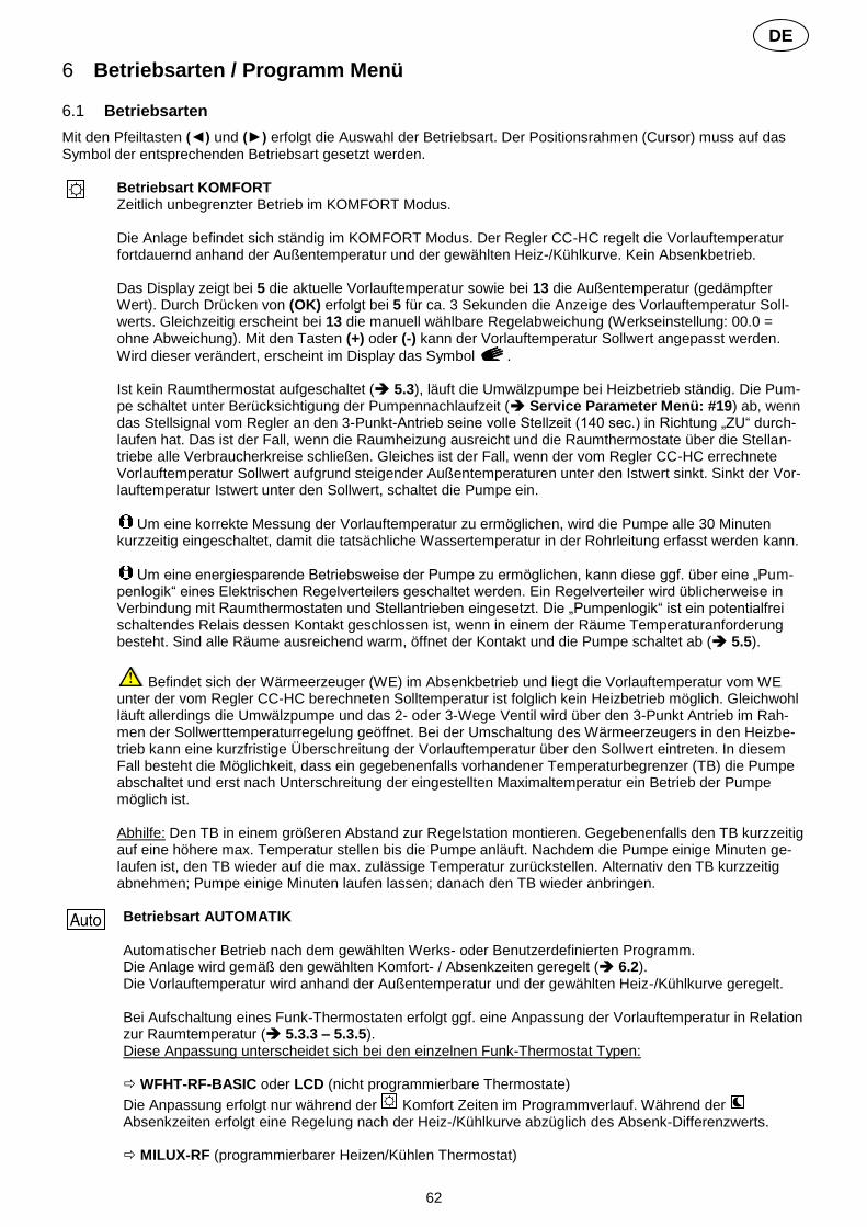
62
DE
6 Betriebsarten / Programm Menü 6.1 Betriebsarten
Mit den Pfeiltasten (◄) und (►) erfolgt die Auswahl der Betriebsart. Der Positionsrahmen (Cursor) muss auf das Symbol der entsprechenden Betriebsart gesetzt werden.
Betriebsart KOMFORT Zeitlich unbegrenzter Betrieb im KOMFORT Modus. Die Anlage befindet sich ständig im KOMFORT Modus. Der Regler CC-HC regelt die Vorlauftemperatur fortdauernd anhand der Außentemperatur und der gewählten Heiz-/Kühlkurve. Kein Absenkbetrieb. Das Display zeigt bei 5 die aktuelle Vorlauftemperatur sowie bei 13 die Außentemperatur (gedämpfter Wert). Durch Drücken von (OK) erfolgt bei 5 für ca. 3 Sekunden die Anzeige des Vorlauftemperatur Soll-werts. Gleichzeitig erscheint bei 13 die manuell wählbare Regelabweichung (Werkseinstellung: 00.0 = ohne Abweichung). Mit den Tasten (+) oder (-) kann der Vorlauftemperatur Sollwert angepasst werden.
Wird dieser verändert, erscheint im Display das Symbol . Ist kein Raumthermostat aufgeschaltet ( 5.3), läuft die Umwälzpumpe bei Heizbetrieb ständig. Die Pum-pe schaltet unter Berücksichtigung der Pumpennachlaufzeit ( Service Parameter Menü: #19) ab, wenn das Stellsignal vom Regler an den 3-Punkt-Antrieb seine volle Stellzeit (140 sec.) in Richtung „ZU“ durch-laufen hat. Das ist der Fall, wenn die Raumheizung ausreicht und die Raumthermostate über die Stellan-triebe alle Verbraucherkreise schließen. Gleiches ist der Fall, wenn der vom Regler CC-HC errechnete Vorlauftemperatur Sollwert aufgrund steigender Außentemperaturen unter den Istwert sinkt. Sinkt der Vor-lauftemperatur Istwert unter den Sollwert, schaltet die Pumpe ein.
Um eine korrekte Messung der Vorlauftemperatur zu ermöglichen, wird die Pumpe alle 30 Minuten kurzzeitig eingeschaltet, damit die tatsächliche Wassertemperatur in der Rohrleitung erfasst werden kann.
Um eine energiesparende Betriebsweise der Pumpe zu ermöglichen, kann diese ggf. über eine „Pum-penlogik“ eines Elektrischen Regelverteilers geschaltet werden. Ein Regelverteiler wird üblicherweise in Verbindung mit Raumthermostaten und Stellantrieben eingesetzt. Die „Pumpenlogik“ ist ein potentialfrei schaltendes Relais dessen Kontakt geschlossen ist, wenn in einem der Räume Temperaturanforderung besteht. Sind alle Räume ausreichend warm, öffnet der Kontakt und die Pumpe schaltet ab ( 5.5).
Befindet sich der Wärmeerzeuger (WE) im Absenkbetrieb und liegt die Vorlauftemperatur vom WE unter der vom Regler CC-HC berechneten Solltemperatur ist folglich kein Heizbetrieb möglich. Gleichwohl läuft allerdings die Umwälzpumpe und das 2- oder 3-Wege Ventil wird über den 3-Punkt Antrieb im Rah-men der Sollwerttemperaturregelung geöffnet. Bei der Umschaltung des Wärmeerzeugers in den Heizbe-trieb kann eine kurzfristige Überschreitung der Vorlauftemperatur über den Sollwert eintreten. In diesem Fall besteht die Möglichkeit, dass ein gegebenenfalls vorhandener Temperaturbegrenzer (TB) die Pumpe abschaltet und erst nach Unterschreitung der eingestellten Maximaltemperatur ein Betrieb der Pumpe möglich ist. Abhilfe: Den TB in einem größeren Abstand zur Regelstation montieren. Gegebenenfalls den TB kurzzeitig auf eine höhere max. Temperatur stellen bis die Pumpe anläuft. Nachdem die Pumpe einige Minuten ge-laufen ist, den TB wieder auf die max. zulässige Temperatur zurückstellen. Alternativ den TB kurzzeitig abnehmen; Pumpe einige Minuten laufen lassen; danach den TB wieder anbringen.
Betriebsart AUTOMATIK Automatischer Betrieb nach dem gewählten Werks- oder Benutzerdefinierten Programm. Die Anlage wird gemäß den gewählten Komfort- / Absenkzeiten geregelt ( 6.2). Die Vorlauftemperatur wird anhand der Außentemperatur und der gewählten Heiz-/Kühlkurve geregelt. Bei Aufschaltung eines Funk-Thermostaten erfolgt ggf. eine Anpassung der Vorlauftemperatur in Relation zur Raumtemperatur ( 5.3.3 – 5.3.5). Diese Anpassung unterscheidet sich bei den einzelnen Funk-Thermostat Typen: WFHT-RF-BASIC oder LCD (nicht programmierbare Thermostate)
Die Anpassung erfolgt nur während der Komfort Zeiten im Programmverlauf. Während der Absenkzeiten erfolgt eine Regelung nach der Heiz-/Kühlkurve abzüglich des Absenk-Differenzwerts. MILUX-RF (programmierbarer Heizen/Kühlen Thermostat)
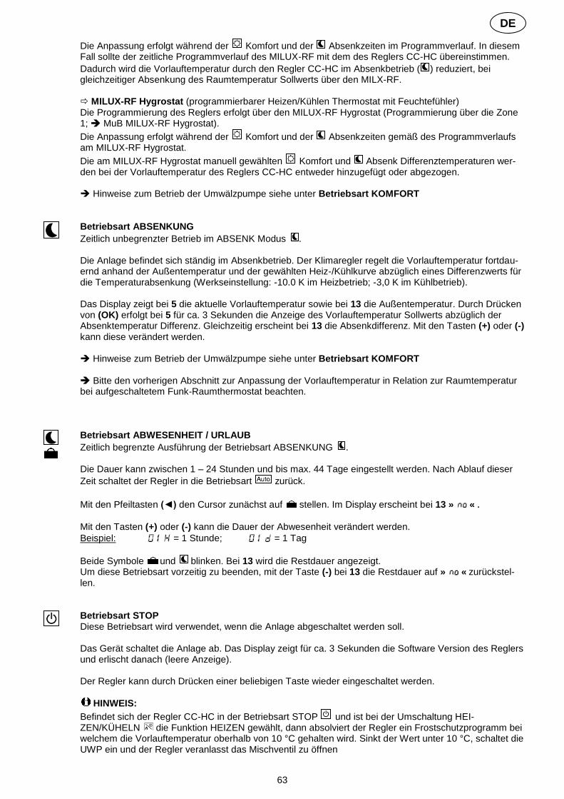
63
DE
Die Anpassung erfolgt während der Komfort und der Absenkzeiten im Programmverlauf. In diesem Fall sollte der zeitliche Programmverlauf des MILUX-RF mit dem des Reglers CC-HC übereinstimmen.
Dadurch wird die Vorlauftemperatur durch den Regler CC-HC im Absenkbetrieb ( ) reduziert, bei gleichzeitiger Absenkung des Raumtemperatur Sollwerts über den MILX-RF. MILUX-RF Hygrostat (programmierbarer Heizen/Kühlen Thermostat mit Feuchtefühler) Die Programmierung des Reglers erfolgt über den MILUX-RF Hygrostat (Programmierung über die Zone 1; MuB MILUX-RF Hygrostat).
Die Anpassung erfolgt während der Komfort und der Absenkzeiten gemäß des Programmverlaufs am MILUX-RF Hygrostat.
Die am MILUX-RF Hygrostat manuell gewählten Komfort und Absenk Differenztemperaturen wer-den bei der Vorlauftemperatur des Reglers CC-HC entweder hinzugefügt oder abgezogen. Hinweise zum Betrieb der Umwälzpumpe siehe unter Betriebsart KOMFORT
Betriebsart ABSENKUNG
Zeitlich unbegrenzter Betrieb im ABSENK Modus . Die Anlage befindet sich ständig im Absenkbetrieb. Der Klimaregler regelt die Vorlauftemperatur fortdau-ernd anhand der Außentemperatur und der gewählten Heiz-/Kühlkurve abzüglich eines Differenzwerts für die Temperaturabsenkung (Werkseinstellung: -10.0 K im Heizbetrieb; -3,0 K im Kühlbetrieb). Das Display zeigt bei 5 die aktuelle Vorlauftemperatur sowie bei 13 die Außentemperatur. Durch Drücken von (OK) erfolgt bei 5 für ca. 3 Sekunden die Anzeige des Vorlauftemperatur Sollwerts abzüglich der Absenktemperatur Differenz. Gleichzeitig erscheint bei 13 die Absenkdifferenz. Mit den Tasten (+) oder (-) kann diese verändert werden. Hinweise zum Betrieb der Umwälzpumpe siehe unter Betriebsart KOMFORT Bitte den vorherigen Abschnitt zur Anpassung der Vorlauftemperatur in Relation zur Raumtemperatur bei aufgeschaltetem Funk-Raumthermostat beachten.
Betriebsart ABWESENHEIT / URLAUB
Zeitlich begrenzte Ausführung der Betriebsart ABSENKUNG . Die Dauer kann zwischen 1 – 24 Stunden und bis max. 44 Tage eingestellt werden. Nach Ablauf dieser
Zeit schaltet der Regler in die Betriebsart zurück.
Mit den Pfeiltasten (◄) den Cursor zunächst auf stellen. Im Display erscheint bei 13 » « . Mit den Tasten (+) oder (-) kann die Dauer der Abwesenheit verändert werden.
Beispiel: = 1 Stunde; = 1 Tag
Beide Symbole und blinken. Bei 13 wird die Restdauer angezeigt. Um diese Betriebsart vorzeitig zu beenden, mit der Taste (-) bei 13 die Restdauer auf » « zurückstel-len.
Betriebsart STOP Diese Betriebsart wird verwendet, wenn die Anlage abgeschaltet werden soll. Das Gerät schaltet die Anlage ab. Das Display zeigt für ca. 3 Sekunden die Software Version des Reglers und erlischt danach (leere Anzeige). Der Regler kann durch Drücken einer beliebigen Taste wieder eingeschaltet werden.
HINWEIS:
Befindet sich der Regler CC-HC in der Betriebsart STOP und ist bei der Umschaltung HEI-ZEN/KÜHELN die Funktion HEIZEN gewählt, dann absolviert der Regler ein Frostschutzprogramm bei welchem die Vorlauftemperatur oberhalb von 10 °C gehalten wird. Sinkt der Wert unter 10 °C, schaltet die UWP ein und der Regler veranlasst das Mischventil zu öffnen

64
DE
Umschaltung HEIZEN / KÜHLEN Diesen Modus nutzen, um zwischen Heiz- und Kühlbetrieb umzuschalten.
Diese Betriebsart ist nur verfügbar, wenn: - der Regler CC-HC für eine reversible Anlage konfiguriert ist (Service Parameter Menü #6 » «) - kein MILUX-RF Hygrostat aufgeschaltet ( 5.3.4) und konfiguriert ist, mit welchem die Umschaltung
HEIZEN/KÜHLEN durchgeführt wird. - Auf keinem der Regler Eingänge In1 oder In2 das Umschaltsignal » « gewählt ist ( 5.5)
ACHTUNG: Wenn eine reversible Wärmepumpe oder ein anderer Kälteerzeuger eingesetzt wird und nicht auf den Regler aufgeschaltet ist, ist darauf zu achten, dass zuerst das Kühlgerät in den Kühlbetrieb geht und erst danach der Regler in den Kühlbetrieb geschaltet wird. Andernfalls können Fehlfunktionen auftreten.
UHRZEIT und WOCHENTAG einstellen In diesem Menü erfolgt die Einstellung der Uhrzeit sowie des aktuellen Wochentags.
Mit dem Cursor zunächst wählen. Danach die Taste (OK) drücken.
Mit den Tasten (+) oder (-) die Minuten einstellen; mit (OK) bestätigen.
Mit den Tasten (+) oder (-) die Stunden einstellen; mit (OK) bestätigen.
Mit den Tasten (+) oder (-) den Wochentag einstellen; mit (OK) bestätigen.
(1 = Montag; 7 = Sonntag)
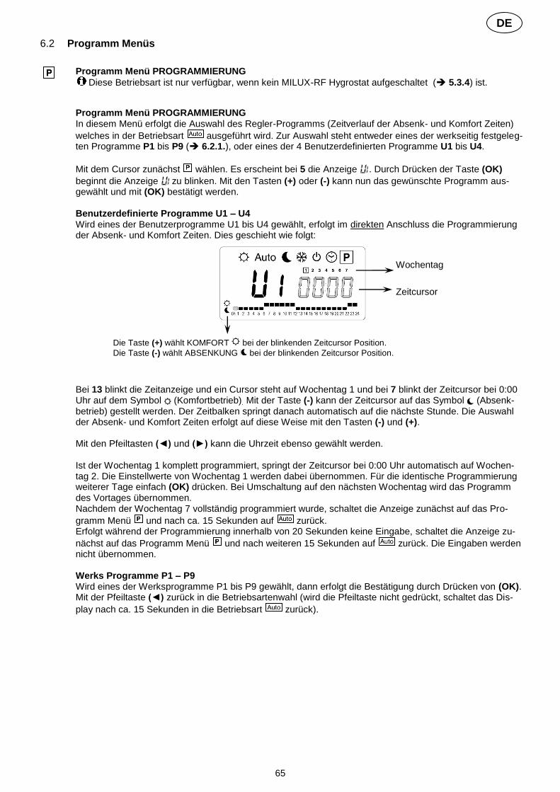
65
DE
6.2 Programm Menüs
Programm Menü PROGRAMMIERUNG
Diese Betriebsart ist nur verfügbar, wenn kein MILUX-RF Hygrostat aufgeschaltet ( 5.3.4) ist.
Programm Menü PROGRAMMIERUNG In diesem Menü erfolgt die Auswahl des Regler-Programms (Zeitverlauf der Absenk- und Komfort Zeiten)
welches in der Betriebsart ausgeführt wird. Zur Auswahl steht entweder eines der werkseitig festgeleg-ten Programme P1 bis P9 ( 6.2.1.), oder eines der 4 Benutzerdefinierten Programme U1 bis U4.
Mit dem Cursor zunächst wählen. Es erscheint bei 5 die Anzeige . Durch Drücken der Taste (OK)
beginnt die Anzeige zu blinken. Mit den Tasten (+) oder (-) kann nun das gewünschte Programm aus-gewählt und mit (OK) bestätigt werden. Benutzerdefinierte Programme U1 – U4 Wird eines der Benutzerprogramme U1 bis U4 gewählt, erfolgt im direkten Anschluss die Programmierung der Absenk- und Komfort Zeiten. Dies geschieht wie folgt:
Bei 13 blinkt die Zeitanzeige und ein Cursor steht auf Wochentag 1 und bei 7 blinkt der Zeitcursor bei 0:00 Uhr auf dem Symbol (Komfortbetrieb). Mit der Taste (-) kann der Zeitcursor auf das Symbol (Absenk-betrieb) gestellt werden. Der Zeitbalken springt danach automatisch auf die nächste Stunde. Die Auswahl der Absenk- und Komfort Zeiten erfolgt auf diese Weise mit den Tasten (-) und (+). Mit den Pfeiltasten (◄) und (►) kann die Uhrzeit ebenso gewählt werden. Ist der Wochentag 1 komplett programmiert, springt der Zeitcursor bei 0:00 Uhr automatisch auf Wochen-tag 2. Die Einstellwerte von Wochentag 1 werden dabei übernommen. Für die identische Programmierung weiterer Tage einfach (OK) drücken. Bei Umschaltung auf den nächsten Wochentag wird das Programm des Vortages übernommen. Nachdem der Wochentag 7 vollständig programmiert wurde, schaltet die Anzeige zunächst auf das Pro-
gramm Menü und nach ca. 15 Sekunden auf zurück. Erfolgt während der Programmierung innerhalb von 20 Sekunden keine Eingabe, schaltet die Anzeige zu-
nächst auf das Programm Menü und nach weiteren 15 Sekunden auf zurück. Die Eingaben werden nicht übernommen. Werks Programme P1 – P9 Wird eines der Werksprogramme P1 bis P9 gewählt, dann erfolgt die Bestätigung durch Drücken von (OK). Mit der Pfeiltaste (◄) zurück in die Betriebsartenwahl (wird die Pfeiltaste nicht gedrückt, schaltet das Dis-
play nach ca. 15 Sekunden in die Betriebsart zurück).
Wochentag
Zeitcursor
Die Taste (+) wählt KOMFORT bei der blinkenden Zeitcursor Position.
Die Taste (-) wählt ABSENKUNG bei der blinkenden Zeitcursor Position.

66
DE
6.2.1 Verlauf der KOMFORT und ABSENK Zeiten der Werksprogramme P1 bis P9
Kurzbeschreibung KOMFORT Zeiten
P1: Morgens, abends und Wochenende Mo - Fr: Sa - So:
07 - 09 und 17 - 23 Uhr 08 - 23 Uhr
P2: Morgens, mittags, abends und Wochen-ende
Mo - Fr: Sa - So:
07 - 09 und 12 - 14 Uhr und 17 - 23 Uhr 08 - 23 Uhr
P3: Tagsüber und Wochenende Mo - Fr: Sa: So:
06 - 23 Uhr 07 - 01 Uhr (So) 07 - 23 Uhr
P4: Abends und Wochenende Mo - Fr: Sa: So:
15 - 23 Uhr 07 - 01 Uhr (So) 07 - 23 Uhr
P5: Morgens und abends (z.B. Badezimmer) Mo - So: Mo - Fr: Sa: So:
07 - 08 Uhr 21 - 23 Uhr 18 - 24 Uhr 19 - 23 Uhr
P6: Morgens, nachmittags und Wochenende Mo - Fr: Sa - So:
06 - 08 und 14 - 21Uhr 07 - 21 Uhr
P7: 7 Uhr bis 20 Uhr (Büro) Mo - Fr: 07 - 20 Uhr
P8: 8 Uhr bis 20 Uhr, Samstag (Shop) Mo - Fr: Sa:
08 - 20 Uhr 08 - 19 Uhr
P9: Wochenende (Wochenendhaus) Fr 14 Uhr durchgehend bis Mo 07 Uhr
Der Regler arbeitet nur in der Betriebsart nach den gewählten KOMFORT und ABSENK Zeiten.

67
DE
7 System Parameter Menü 7.1 Einstellung der System Parameter
In diesem Menü werden die wesentlichen Parameter zum Betrieb der Anlage eingestellt.
Um in dieses Menü zu gelangen, zunächst den Cursor auf , oder stellen. Danach (OK) 10 Sekunden
gedrückt halten. Im Display erscheint und die Werkseinstellung Hot für HEIZEN als Anlagentyp. Mit (+) oder (-)
Anlagentyp wählen, zum bestätigen des Anlagentyps (OK) drücken.
Mit den Pfeiltasten (◄) und (►) werden die Parameter ausgewählt.
Zum Verändern der Parameter (OK) drücken und mit (+) oder (-) verändern oder mit (OK) umschalten.
Um das Menü zu verlassen (►) drücken, bis » «. Mit (OK) beenden. Der Cursor wechselt auf .
SYSTEM PARAMETER
Anzeige Parameter-Nr. (#)
Beschreibung Parameter Werks Einstellung
Alternative Einstellung
Benutzer Einstellung
0
Anlagen Typ Die Parameter sind abhängig von der Auswahl des Anlagen Typs. Beispiel: Der Parameter „Kühlkurve“ steht nicht zur Verfügung, wenn als Anlagen Typ HEIZEN » « gewählt wurde.
,
Anlagen Typ HEIZEN
Anlagen Typ KÜHLEN
Anlagen Typ reversibel (HEI-ZEN/KÜHLEN)
Parameter HEIZEN
1
Heizkurve ( 7.2.) Vorlauftemperatur gemäß Außentem-peraturkurve
0.7 0.1 bis 5
2
Maximalwert Vorlauftemperatur HEIZEN 45 °C
( +1 °C) bis 100 °C
3
Minimalwert Vorlauftemperatur HEI-ZEN 10 °C 1 bis ( -1 °C)
Parameter KÜHLEN
nur verfügbar, wenn bei Parameter #0 » « oder » « gewählt wurde.
1
Kühlkurve ( 7.2.) Vorlauftemperatur gemäß Außentem-peraturkurve
0.4 0.1 bis 5
2
Maximalwert Vorlauftemperatur KÜHLEN 30 °C
( +1 °C) bis 100 °C
3
Minimalwert Vorlauftemperatur KÜH-LEN 15 °C 1 bis ( -1 °C)
4
Anlagen Art
: Anlage mit Zonenventil Der Ausgang COLD steuert ein Zonenven-til zur Umschaltung HEIZEN/KÜHLEN. - Bei HEIZEN ist der Kontakt stromlos; - Bei KÜHLEN ist der Kontakt unter Span-nung.
Für weitere Infor-mationen bzw.
Erläuterung bitte die Schaltschemen beachten ( 10)

68
DE
Der Ausgang HEAT steuert den Wärme-erzeuger.
: Anlage mit separaten Wärme- und Kälteerzeuger Für jedes Gerät steht ein Ausgang zur Verfügung.
Die beiden folgenden Auswahl Parameter wurden speziell für Anlagen mit 2 Pum-penkreisen (z.B. WattMix) mit jeweils einer eigenen Umwälzpumpe erstellt. Die Um-wälzpumpe für Kreis 2 wird auf Ausgang COLD aufgelegt und über den Raumther-mostat2 gesteuert ( 5.4.)
: Flächenheizung/-kühlung und Radiatorenheizung
Die Pumpe2 für Di-
rektkreis Radiatoren-heizung wird im
Kühlbetrieb abge-schaltet.
Flächenheizung/-kühlung und Klimagerät (Fan Coil/Aircondition)
Die Pumpe2 steuert
Fan Coil Kreis
5
Auswahl Raumthermostat: No: ohne Thermostat Yes: Kabel Thermostat aufgelegt rF: Funk-Thermostat aufgeschaltet
,
Der nachfolgende Parameter #6 ist nur verfügbar, wenn bei Parameter #5 » « gewählt wurde
6
Auswahl Kabel Raumthermostat:
: Standard Thermostat (Heizen)
: Reversibler Thermostat (Heizen/Kühlen)
Der nachfolgende Parameter #7 ist nur verfügbar, wenn bei Parameter #5 » « oder » « gewählt wurde UND ein Rücklauftemperaturfühler aufgelegt ist. ( 5.3)
7
Boost Funktion Heizbetrieb: Die Vorlauftemperatur wird um 20 % erhöht, wenn die Rück-lauftemperatur niedriger als der Vor-lauftemperatur Sollwert abzüglich Einstellwert » « ist. RTIst < VLSoll - = VLSoll +20 % Kühlbetrieb: Die Vorlauftemperatur wird um 20 % reduziert, wenn die Rücklauftemperatur niedriger als der Vorlauftemperatur Sollwert abzüglich Einstellwert » « ist. RTIst < VLSoll - = VLSoll -20 % (OK) drücken, um die aktuelle Rück-lauftemperatur anzuzeigen.
Ist kein Rücklauftemperatur-fühler aufgelegt, wird die Boost Funktion umgangen.
10.0 °C 1 – 20 °C
Der nachfolgende Parameter #8 ist nur verfügbar, wenn bei Parameter #5 » « gewählt wurde
8
FUNK-KONFIGURATION mit Funk-Thermostat zur Raumtemperaturaufschaltung1 6. Die Taste (OK) drücken. Durch Drücken von (+) oder (-) schaltet der Regler in den
Funk-Initialisierungsmodus. Im Display erscheint » «.

69
DE
7. Bringen Sie den Funk-Thermostat in den Funk-Initialisierungsmodus ( MuB). 8. Bei erfolgreicher Zuordnung sendet der Funk-Thermostat ein Funksignal an den Reg-
ler. Im Display wird anstelle von » « der Raumtemperatur Istwert blinkend ange-zeigt.
9. Durch Drücken von (OK) am Regler wird der Vorgang abgeschlossen. 10. Beenden Sie am Funk-Thermostat den Funk-Initialisierungsmodus ( MuB). Die Auswahl » « trennt den Funk-Thermostat vom Regler bzw. beendet die Funktion der Raumtemperaturaufschaltung.
Die Aufschaltung von Funk-Thermostaten ist nur mit den passenden Geräten möglich.
Der nachfolgende Parameter #9 ist nur verfügbar, wenn bei Parameter #5 » « gewählt wurde UND bei Para-meter #4 entweder » « oder » « ausgewählt ist.
9
FUNK-KONFIGURATION mit Funk-Thermostat zur Raumtemperaturaufschaltung2 Gleiches Vorgehen wie unter Parameter #8 beschrieben.
Der nachfolgende Parameter #10 ist nur verfügbar, wenn bei Parameter #5 » « gewählt wurde
10
Offset-Wert für Funk-Thermostate Erläuterung ( 5.3.3). 3.0 °C 0.1 - 9.9 °C
11
Eingang In1 ( 5.5.1.)
: Bei Parameter #5 wurde » « gewählt. Kabel-Thermostat auf Eingang In1.
: Bei Parameter #5 wurde » « oder » « gewählt.
Eingang In1 ohne Funktion.
(nicht
veränderbar)
, ,
oder
: Anlegethermostat auf Eingang In1. Wenn Übertemperatur erreicht wird (Kon-
takt offen), wird die Pumpe1 abgeschaltet und der Antrieb schließt.
Ist der Kontakt zwischen 2 und In1 offen, dann
schaltet die Pum-pe AUS.
: Umschaltsignal HEIZEN/KÜHLEN auf Eingang In1.
Entweder potentialfreies Signal auf Ein-gang In1 und Eingang 2 oder Spannungs-eingang auf Eingang In1.
HEIZEN: kein Signal (offener Kreis) KÜHLEN: Spannungseingang (geschlos-
sener Kreis)
Das Umschaltsignal
kann von einer Wärmepumpe
bereitgestellt wer-den. Bitte die tech-nischen Angaben
bzw. Kompatibilität vor Anschluss
prüfen.
: Relaisausgang eines Regelverteilers auf Eingang In1.
Entweder potentialfreies Signal auf Ein-gang In1 und Eingang 2 oder Span-nungseingang auf Eingang In1.
PUMPE EIN: Spannungseingang (ge-schlossener Kreis)
PUMPE AUS: kein Signal (offener Kreis)
Ist der Kontakt zwischen 2 und In1 offen, dann
schaltet die Pum-pe AUS.
12
Eingang In2 ( 5.5.2.)
: Bei Parameter #5 wurde » « gewählt und bei Parameter #4 wurde » « oder » « gewählt.
Kabel-Thermostat auf Eingang In2.
: Bei Parameter #5 wurde » « oder » « gewählt.
Eingang In2 ohne Funktion.
(nicht
veränderbar)
, ,
oder

70
DE
: Anlegethermostat auf Eingang In2. Wenn Übertemperatur erreicht wird
(Kontakt offen), dann erfolgt bei folgen-der Auswahl der Parameter #4:
» « oder » «: Abschaltung der Pumpe1 und der Antrieb schließt. » « oder » «: Abschaltung der Pumpe2.
Ist der Kontakt zwischen 2 und In2 offen, dann
schaltet die Pum-pe AUS.
: Umschaltsignal HEIZEN/KÜHLEN auf Eingang In2.
Entweder potentialfreies Signal auf Ein-gang In2 und Eingang 2 oder Span-nungseingang auf Eingang In2.
HEIZEN: kein Signal (offener Kreis) KÜHLEN: Spannungseingang (geschlos-
sener Kreis)
Das Umschaltsignal
kann von einer Wärmepumpe
bereitgestellt wer-den. Bitte die tech-nischen Angaben
bzw. Kompatibilität vor Anschluss
prüfen
: Relaisausgang eines Regelverteilers auf Eingang In2.
» « oder » «: Abschaltung der Pumpe1 und der Antrieb schließt. » « oder » «: Abschaltung der Pumpe2.
Ist der Kontakt zwischen 2 und In2 offen, dann
schaltet die Pum-pe AUS.
13
Außentemperaturfühler Menü : Kabel-Außenfühler aufgelegt.
: ohne Außenfühler bei Auswahl » « arbeitet der Regler
nach einem fixen Vorlauftemperatur-Sollwert ( Parameter #14).
: Funk-Außenfühler aufgeschaltet.
,
Der nachfolgende Parameter #14 ist nur verfügbar, wenn kein Außenfühler angeschlossen ist und bei Parameter #13 » « gewählt wurde.
14
Fest-Wert Außentemperatur Einstellung eines festen Außentemperatur-werts zur Vorlauftemperaturregelung. Die Vorlauftemperatur wird konstant nach der eingestellten Außentemperatur und der zu-geordneten Heizkurve geregelt. Beispiel:
= 0 °C. Gewählte Heizkurve = 1. Ergibt VLSoll ca. 40 °C Zur Feineinstellung VLSoll kann in den Be-triebsarten KOMFORT oder ABSEN-KUNG der Sollwert angepasst werden ( 6.1.)
00.0 °C -49.0 - +50.0 °C
Der nachfolgende Parameter #14 ist nur verfügbar, wenn bei Parameter #13 » « gewählt wurde
14
FUNK-KONFIGURATION mit Funk-Außenfühler Gleiches Vorgehen wie unter Parameter #8 beschrieben.
16
Temperaturanzeige in °C or °F °C °F
17
Zeitanzeige 24 Stunden oder 12 Stunden 24 h 12 h Am/Pm

71
DE
18
Festsitzschutz (ak-
tiv)
(nicht aktiv)
Bei Auswahl werden Pumpe und Stellantrieb um 12 Uhr Mittags für 2 Minuten betätigt, falls diese 24 Stunden nicht aktiv waren. (12:00: Pumpe EIN für 1 Minute; 12:01 Antrieb AUF für 2 Minuten; 12:03 Antrieb ZU für 2 Minuten)
Der nachfolgende Parameter #19 wird nur verwendet wenn kein Funk-Thermostat aufgeschaltet und die Eingän-ge In1 und In2 nicht mit einem Signal von C_b und Aqu beaufschlagt sind.
19
Pumpennachlaufzeit Die Pumpe schaltet nach Ablauf dieser Zeit-dauer AUS, wenn der Raumthermostat ent-sprechend anfordert ( 5.3.), oder wenn das 3-Wege Ventil komplett geschlossen ist. Diese Funktion verhindert ein ständiges EIN/AUS schalten der Pumpe durch das Auf-schalten eines Thermostaten mit PWM Regel-zyklus.
030
Der Wert sollte >/= 2 x Re-
gelzyklus PWM des
Raum-thermos-
taten betragen.
001 – 060 über 060 Wert
unbegrenzt » ___ «
20
Handbetrieb (oder Testfunktion) Stellmotor bzw. 2/3-Wege Ventil Durch Drücken von (+) öffnet der Stellantrieb. Im Display erscheint „OPEN“ und . Durch Drücken von (–) schließt der Stellantrieb. Im Display erscheint „CLOS“ und . Durch Drücken von (◄) oder (►) wird die aktuelle Position des Stellantriebs gehalten. Im Display erscheint „STOP“.
Es besteht ein Zeitversatz von 15 Sekunden zwischen dem Umschalten von „OPEN“ nach „CLOSE“ und umgekehrt.
21
Estrich Funktionsheizen
Das Programm wird durch Auswahl von » « gestartet und läuft automatisch ab. Es wird die Anzahl der Tage bis zum Ende des Aufheizprogramms angezeigt. Während 3 Ta-gen wird die Vorlauftemperatur auf 25 °C gehalten (Tage 7, 6, 5). Die nächsten 4 Tage wird der Maximalwert Vorlauftemperatur gehalten (Tage 4, 3, 2, 1).
22
Estrich Belegreifheizen 13 Tage, bei Aktivierung der
Option
7 bis 60 Tage wählbar
Das Programm wird durch Auswahl von » « gestartet und läuft automatisch ab. Es wird die Anzahl der Tage bis zum Ende des Aufheizprogramms angezeigt. Temperaturverlauf:
1) bzw. Maximalwert Vorlauftemperatur HEIZEN Parameter #2
Tag1 Tag2 Tag3 Tag4 Tag5 Tag6 Tag7 Tag8 Tag9 Tag10 Tag11-56 Ende1 Ende2 Ende3 Ende4
25 °C 35 °C 45 °C 1) 55 °C 1) 55 °C 1) 55 °C 1) 55 °C 1) 55 °C 1) 55 °C 1) 55 °C 1) 55 °C 1) 45 °C 1) 35 °C 25 °C
23
Reset function Durch Drücken von (OK) für ca. 5 Sekunden werden alle System Parameter, die Uhrzeit
und Wochentag sowie die Benutzerprogramme in auf Werkseinstellung zurückgesetzt. Ebenso wird eine evtl. bestehende Funk-Konfiguration gelöscht. Der Cursor wechselt auf
.
24
Durch Drücken von (OK) wird das System Parameter Menü verlassen. Der Cursor wechselt auf .
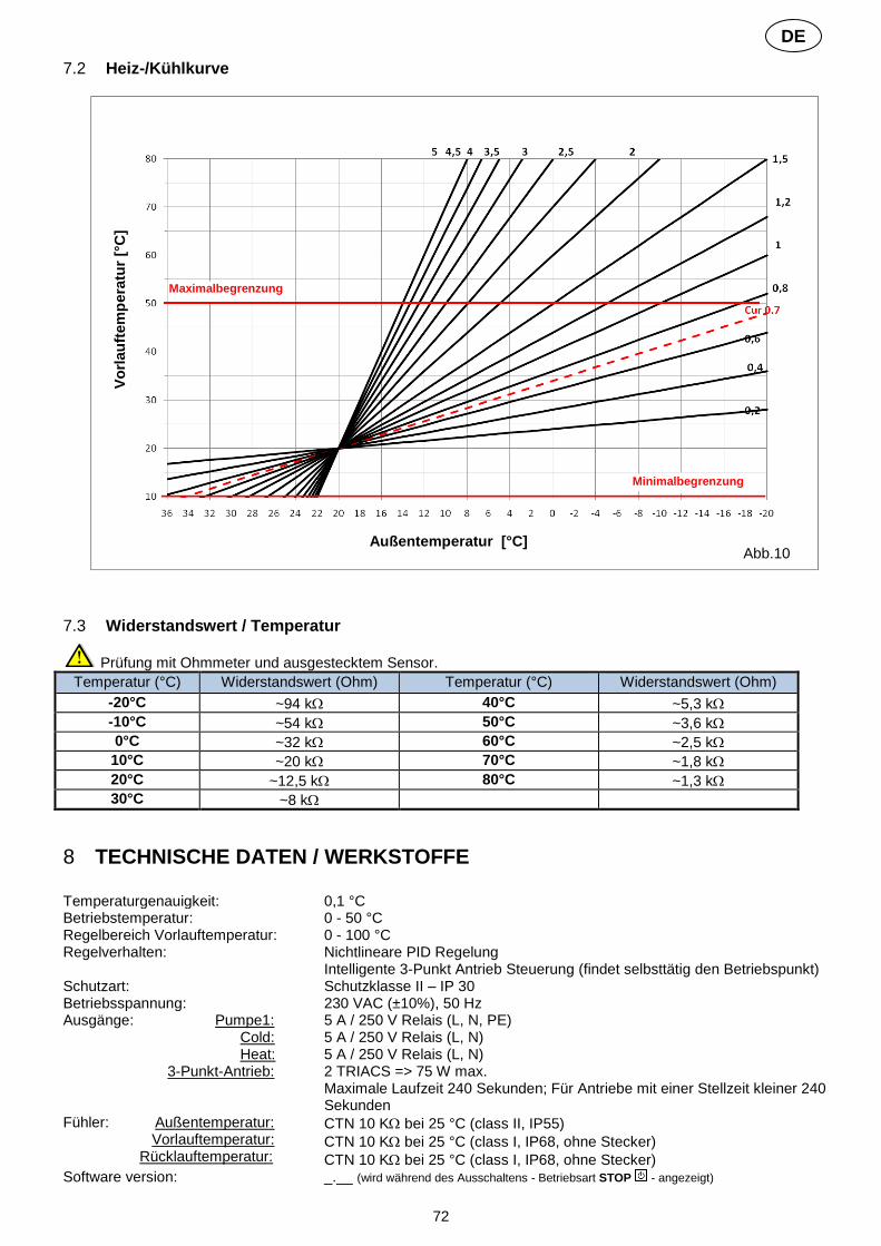
72
DE
7.2 Heiz-/Kühlkurve
7.3 Widerstandswert / Temperatur
Prüfung mit Ohmmeter und ausgestecktem Sensor.
Temperatur (°C) Widerstandswert (Ohm) Temperatur (°C) Widerstandswert (Ohm)
-20°C ~94 k 40°C ~5,3 k
-10°C ~54 k 50°C ~3,6 k
0°C ~32 k 60°C ~2,5 k
10°C ~20 k 70°C ~1,8 k
20°C ~12,5 k 80°C ~1,3 k
30°C ~8 k
8 TECHNISCHE DATEN / WERKSTOFFE
Temperaturgenauigkeit: 0,1 °C Betriebstemperatur: 0 - 50 °C Regelbereich Vorlauftemperatur: 0 - 100 °C Regelverhalten: Nichtlineare PID Regelung
Intelligente 3-Punkt Antrieb Steuerung (findet selbsttätig den Betriebspunkt) Schutzart: Schutzklasse II – IP 30 Betriebsspannung: 230 VAC (±10%), 50 Hz Ausgänge: Pumpe1: Cold: Heat: 3-Punkt-Antrieb:
5 A / 250 V Relais (L, N, PE) 5 A / 250 V Relais (L, N) 5 A / 250 V Relais (L, N) 2 TRIACS => 75 W max. Maximale Laufzeit 240 Sekunden; Für Antriebe mit einer Stellzeit kleiner 240 Sekunden
Fühler: Außentemperatur: Vorlauftemperatur: Rücklauftemperatur:
CTN 10 K bei 25 °C (class II, IP55)
CTN 10 K bei 25 °C (class I, IP68, ohne Stecker)
CTN 10 K bei 25 °C (class I, IP68, ohne Stecker) Software version: _.__ (wird während des Ausschaltens - Betriebsart STOP - angezeigt)
Abb.10
Maximalbegrenzung
Minimalbegrenzung
Vo
rlau
ftem
pera
tur
[°C
]
Außentemperatur [°C]

73
DE
9 ABHILFE BEI STÖRUNGEN
X. STÖRUNG
X.X Mögliche Ursache Abhilfe
1. Display zeigt
1.1 im rechten Bereich des Display Fühler Unterbrechung Außentemperaturfühler
Korrekten Anschluss des Fühlerkabels prüfen. Kabel auf Beschädigungen überprüfen. Gegebenenfalls Kabel oder Fühler tauschen.
1.2 im linken Bereich des Display Fühler Unterbrechung Vorlauftemperaturfühler
Korrekten Anschluss des Fühlerkabels prüfen. Kabel auf Beschädigungen überprüfen. Gegebenenfalls Kabel oder Fühler tauschen.
2. Falsche Vorlauftemperatur
2.1 Vorlauftemperatur verkehrt Der Angezeigte Wert VLSoll stimmt nicht mit der Regelkurve überein.
Offset-Wert überprüfen ( 6.1). KOMFORT und ABSENKUNG Temperatur-Offset.
2.2 Vorlauftemperatur zu hoch wegen falsch ange-schlossenem 3-Punkt Antrieb (Wirksinn verkehrt)
Anschluss des Antriebs an den Regler überprüfen ( 5.2).
2.3 Vorlauftemperatur zu gering wegen falsch ange-schlossenem 3-Punkt Antrieb (Wirksinn verkehrt)
Anschluss des Antriebs an den Regler überprüfen ( 5.2).
2.4 Verkehrte Betriebsart gewählt Betriebsart richtig auswählen.
2.5 Während Regler im AUTOMATIK Betrieb läuft: - Falsche Programmzuordnung - Uhrzeit / Wochentag falsch eingestellt
- Programmierung Werks- oder Benutzerprogramm prüfen und auf richtige Wahl der Heiz- und Absenkzeiten achten.
- Einstellung Uhrzeit und Wochentag überprüfen.
3. Pumpe oder 3-Punkt-Antrieb läuft nicht
3.1 Kabel verkehrt angeschlossen. Elektrischen Anschluss überprüfen ( 5.2).
3.2 Pumpe ist an einen Temperaturbegrenzer ange-schlossen.
- Elektrischen Anschluss überprüfen ( 5.2). - Einstellung der Maximaltemperatur am TB prüfen. - Umgebungstemperatur am TB prüfen, ggf. Position ändern. - TB auf Funktion prüfen; Gegebenenfalls austauschen.
HINWEIS:
Eingabe Sperre
Um ungewollte Fehleingaben nach der Erstinbetriebnahme zu verhindern, sind alle kritischen Parameter nach 4 Stunden Spannungsversorgung nicht mehr zugänglich. Um die Parameter danach wieder zu ändern, muss einfach die Stromversorgung kurz unterbrochen werden. Durch die Stromunterbrechung selbst (auch bei Netzausfall etc.) gehen jedoch keine Einstellungen verloren. Weniger kritische Parameter sind jedoch auch nach diesen 4 Stunden zugänglich.

74
DE
10 HYDRAULIK SCHEMATA BEISPIELE
10.1 Installation Wärmeerzeuger mit Heizkreis und D.H.W Priorität
(1 Flächenheiz-/-kühlkreis)
10.2 Installation mit getrennten Wärme- und Kälteerzeugern und einem Zonen-/Umschaltventil
(1 Flächenheizung/-kühlung)
AF
Temperaturbegrenzer
1
M M
System Parameter Menü:
#4
#5
#11 D.H.W.Priority
Optionaler Rücklauftemperaturfühler (wenn kein RF Thermostat angeschlossen ist) Vorlauftemperaturfühler
Pumpe1
3-Wege Mischventil
HEAT Ausgang
- Raumtemperaturregelung
*Option RF
Aquastat
D.H.W.
AF
Temperaturbegrenzer
2
M
1
M M
System Parameter Menü:
#4
#5
#8
Optionaler Rücklauftemperaturfühler (wenn kein RF Thermostat angeschlossen ist) Vorlauftemperaturfühler
Pumpe1
3-Wege Mischventil
Signal 3-Wege Ventil (im Kühlbetrieb)
HEAT Ausgang
- Raumtemperaturregelung - Luftfeuchte Erfassung
*Option RF
COLD Ausgang

75
DE
10.3 Installation mit getrennten Wärme- und Kälteerzeugern
(1 Flächenheizung/-kühlung)
10.4 Installation mit reversibler Wärmepumpe
(1 Flächenheiz-/-kühlkreis, 1 Direktkreis Radiatorenheizung)
AF
Temperaturbegrenzer
2 1
M M
Optionaler Rücklauftemperaturfühler (wenn kein RF Thermostat angeschlossen ist) Vorlauftemperaturfühler
Pumpe1
3-Wege Mischventil
COLD Ausgang HEAT Ausgang
System Pa-rameter Menü:
#4
#5
#8
- Raumtemperaturregelung - Luftfeuchte Erfassung
*Option RF
AF
Temperaturbegrenzer
1
M M
- Raumtemperaturregelung - Luftfeuchte Erfassung
Vorlauftemperaturfühler
Pumpe1
3-Wege-Mischventil
Umschaltsignal
von Wärmepumpe
Pumpe2
- Raumtemperaturregelung
HP
Aquastat
System Parameter Menü: #4
#5 #8 #9
#11)
#12
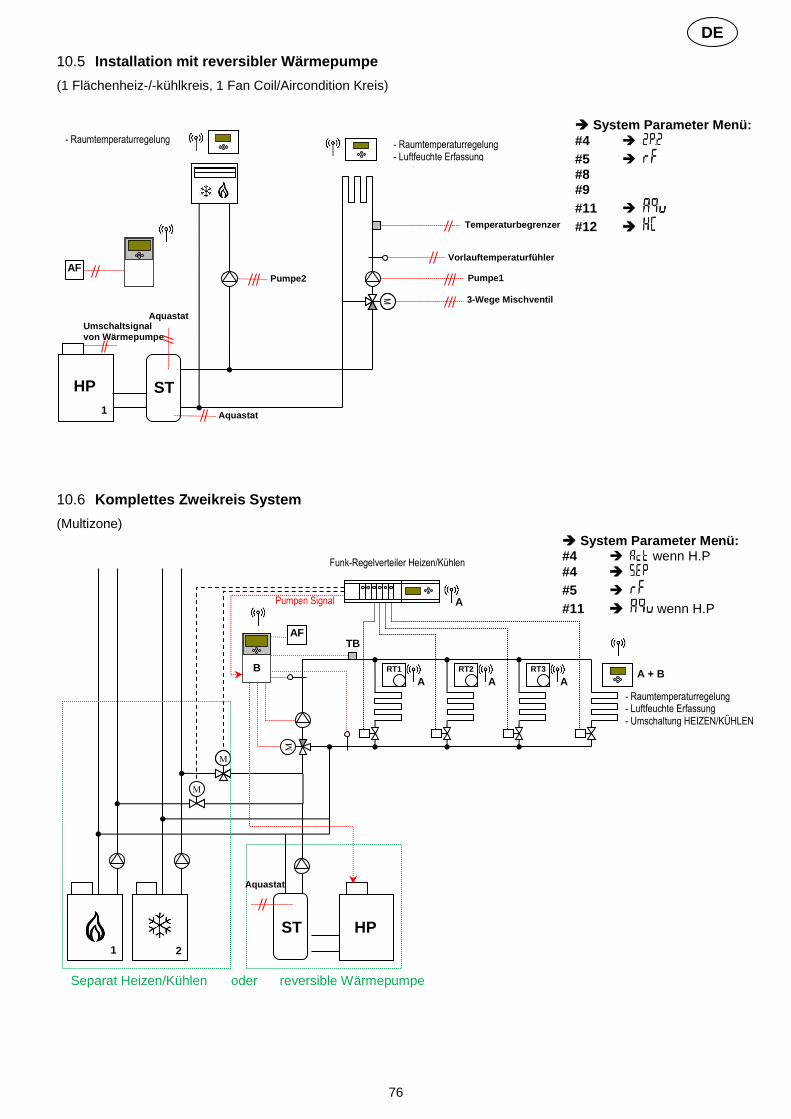
76
DE
10.5 Installation mit reversibler Wärmepumpe
(1 Flächenheiz-/-kühlkreis, 1 Fan Coil/Aircondition Kreis)
10.6 Komplettes Zweikreis System
(Multizone)
AF
Temperaturbegrenzer
1
M M
- Raumtemperaturregelung - Luftfeuchte Erfassung
Vorlauftemperaturfühler
Pumpe1
3-Wege Mischventil
Umschaltsignal von Wärmepumpe
Pumpe2
- Raumtemperaturregelung
HP
Aquastat
ST
Aquastat
M
AF
TB
RT3 RT2 RT1
M
A A + B
A
A
B
1 2
M
M
Funk-Regelverteiler Heizen/Kühlen
A
HP ST
Pumpen Signal
Aquastat
Separat Heizen/Kühlen oder reversible Wärmepumpe
- Raumtemperaturregelung - Luftfeuchte Erfassung - Umschaltung HEIZEN/KÜHLEN
System Parameter Menü:
#4
#5 #8 #9
#11
#12
System Parameter Menü: #4 wenn H.P
#4
#5
#11 wenn H.P

77
PPLIMF08157Cg Rev : 20/12/16