mts sensor temposonics ep el can 2012 - otkon achid -shi, j p n tel. + 81-42-775-3838 fax +...
TRANSCRIPT
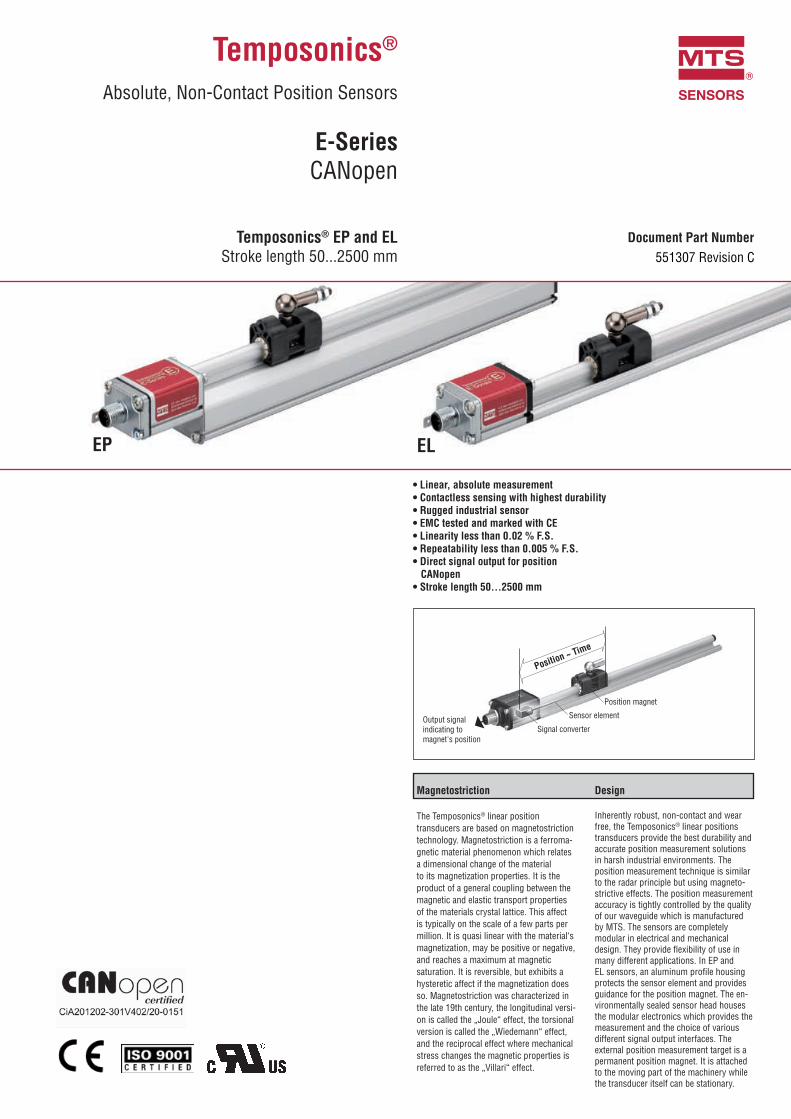
EP EL
Output signalindicating tomagnet's position
Position ~ Time
Signal converter
Sensor element
Position magnet
The Temposonics® linear position transducers are based on magnetostriction technology. Magnetostriction is a ferroma-gnetic material phenomenon which relates a dimensional change of the material to its magnetization properties. It is the product of a general coupling between the magnetic and elastic transport properties of the materials crystal lattice. This affect is typically on the scale of a few parts per million. It is quasi linear with the material‘s magnetization, may be positive or negative, and reaches a maximum at magnetic saturation. It is reversible, but exhibits a hysteretic affect if the magnetization does so. Magnetostriction was characterized in the late 19th century, the longitudinal versi-on is called the „Joule“ effect, the torsional version is called the „Wiedemann“ effect, and the reciprocal effect where mechanical stress changes the magnetic properties is referred to as the „Villari“ effect.
Inherently robust, non-contact and wear free, the Temposonics® linear positions transducers provide the best durability and accurate position measurement solutions in harsh industrial environments. The position measurement technique is similar to the radar principle but using magneto-strictive effects. The position measurement accuracy is tightly controlled by the quality of our waveguide which is manufactured by MTS. The sensors are completely modular in electrical and mechanical design. They provide flexibility of use in many different applications. In EP and EL sensors, an aluminum profile housing protects the sensor element and provides guidance for the position magnet. The en-vironmentally sealed sensor head houses the modular electronics which provides the measurement and the choice of various different signal output interfaces. The external position measurement target is a permanent position magnet. It is attached to the moving part of the machinery while the transducer itself can be stationary.
®
Absolute, Non-Contact Position Sensors
CANopen
®
Stroke length 50...2500 mm 551307 Revision C
®
CANopen
I 2 I
®
MTS Sensors continues to establish new performance standards for low-cost, fully-industrial, durable position sensors based on the magnetostrictive technology. This principle for accurate and non-contact measurement of linear-position sensing was developed 30 years ago by MTS and is used with outstanding success in a large variety of industrial applications.The Temposonics® EP and EL sensors consist of robust aluminum profile-style housings that offer flexible mounting configurations and easy installation. Sensors EP and EL are ideal for demanding industrial applications where simple, reliable non-contact feedback is essential.
Measured variable positionStroke length 50...2500 mm
Interface CAN System ISO-DIS 11898Data protocol CANopen: CIA Standard DS 301 V3.0 / Encoder Profile DS 406 V3.1Baud rate, kBit/s 1000 800 500 250 125 Cable length, m < 25 < 50 < 100 < 250 < 500
The sensor will be supplied with ordered baud rate, which is changeable by customerUpdate frequency 1 ms
Resolution 10 µm, 20 µmVelocity 1 mm / sLinearity 1 ≤ ± 0.02 % F.S. (minimum ± 60 µm)Repeatability ≤ ± 0.005 % F.S. (minimum ± 20 µm)
Magnet speed anyOperating temperature -40 °C...+75 °CDew point, humidity 90 % rel. humidity, no condensationElectronic ingress protection 2 IP67 with proper mating connectorShock test 100 g (single shock) IEC-Standard 60068-2-27Vibration test 15 g / 10...2000 Hz IEC-Standard 60068-2-6 (resonance frequencies excluded)EMC test Electromagnetic emission EN 61000-6-4 (for use in industrial environment)
Electromagnetic immunity EN 61000-6-2The sensor meets the requirements of the EC directives and is marked with CE
Sensor enclosure aluminumSensor housing aluminum Position magnet type magnet slider hard ferrite, block magnet plastic
Mounting type adjustable mounting clamps
Connection type 5 pin connector M12Supply voltage 24 VDC (+20 % / -15 %); UL Recognition requires an approved power supply with energy limitation (UL 61010-1),
or Class 2 rating according to the National Electrical Code (USA) / Canadian Electrical Code. Current consumption max. 90 mARipple < 0.28 VppDielectric strength 500 VDC (DC ground to machine ground)Polarity protection up to -30 VDCOvervoltage protection up to 36 VDC
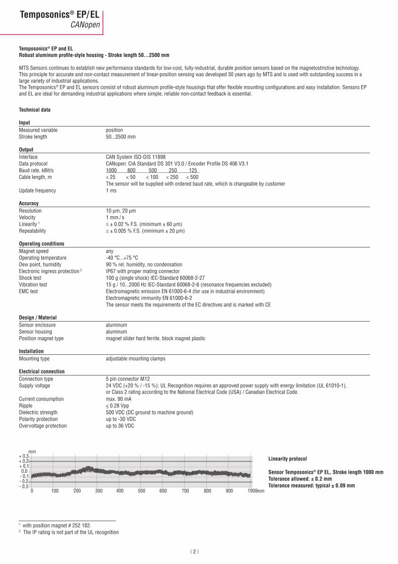
mm+ 0,3+ 0,2
- 0,1
+ 0,10,0
- 0,2- 0,3
0 100 200 300 400 500 600 700 800 900 1000mm
®
1 with position magnet # 252 182.2 The IP rating is not part of the UL recognition

®
CANopen
I 3 I
®
®
5068
Mounting clamp
3548.813 5 pin
40
14.6
Stroke length 50...2500 68inactive
29
M12 x 1
Start position
35 Stroke length 50...2500 68inactive
4513
12.5
35.6
27
5068
Mounting clamp
5 pin
2
Start position
M12 x 1
14.6
15
5 pin connector M12
M435
Acceptablegap 3 mm(± 1 mm)Non-magnetizable
support, screws
32.5
M4 Mounting support
Position magnet
U-Magnet “M“*
Block magnet “L”
Start position
Start position
Connector D34
Acce
ptab
le g
ap
3mm
(+ 2
mm
)
19
20.7
41
Magnet slider “S”Start position
All dimensions in mm
3 only for EP transducers
3
®
CANopen
I 4 I
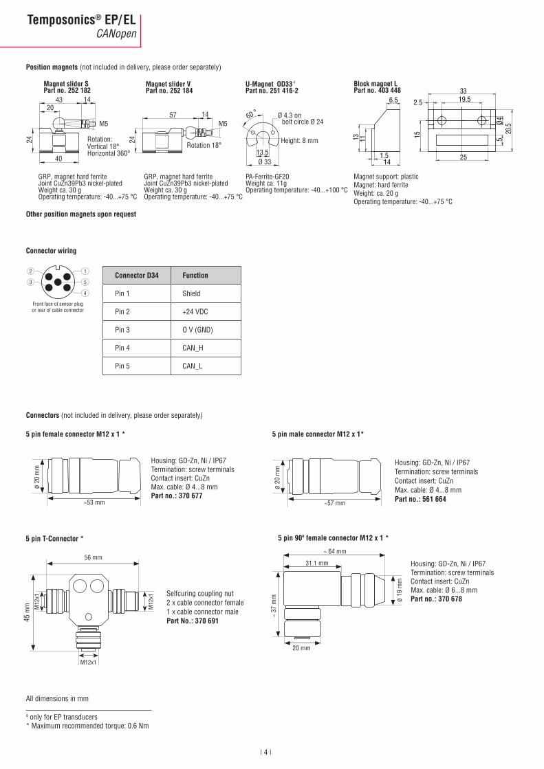
(not included in delivery, please order separately)
Magnet slider S Part no. 252 182 Part no. 252 184
Magnet slider V U-Magnet OD33*Part no. 251 416-2
20
24
43 14
M5
40
Rotation:Vertical 18°Horizontal 360°
Ø 33
1457
Rotation 18°
60 °
13.5
Height: 8 mm
Ø 4.3 on bolt circle Ø 24
24M5
GRP, magnet hard ferriteJoint CuZn39Pb3 nickel-platedWeight ca. 30 gOperating temperature: -40...+75 °C
GRP, magnet hard ferriteJoint CuZn39Pb3 nickel-platedWeight ca. 30 g Operating temperature: -40...+75 °C
PA-Ferrite-GF20Weight ca. 11gOperating temperature: -40...+100 °C
2.5 19.533
25
520
.5
15
6.5
14
13 11
1.5
Ø4
Block magnet LPart no. 403 448
Magnet support: plasticMagnet: hard ferriteWeight: ca. 20 gOperating temperature: -40...+75 °C
Pin 1 Shield
Pin 2 +24 VDC
Pin 3 O V (GND)
Pin 4 CAN_H
Pin 5 CAN_L
1
5
4
2
3
Front face of sensor plugor rear of cable connector
All dimensions in mm
Selfcuring coupling nut2 x cable connector female1 x cable connector male
56 mm
45 m
m M12
x1
M12x1
M12
x1
Housing: GD-Zn, Ni / IP67Termination: screw terminalsContact insert: CuZnMax. cable: Ø 4...8 mm ø
20 m
m
~53 mm
Housing: GD-Zn, Ni / IP67Termination: screw terminalsContact insert: CuZnMax. cable: Ø 6...8 mm
~ 64 mm
31.1 mm
ø 19
mm
20 mm
~ 37
mm
4
(not included in delivery, please order separately)
Housing: GD-Zn, Ni / IP67Termination: screw terminalsContact insert: CuZnMax. cable: Ø 4...8 mm ø
20 m
m
~57 mm
4 only for EP transducers* Maximum recommended torque: 0.6 Nm

®
CANopen
I 5 I
The sensor is fixed on a flat surface of the machine with the mounting clamps. The number of clamps is dependent on the length of the sensor. The clamps should be distributed evenly along the profile. We recommend M5 x 20 (DIN 6912) screws for attachment to be tightened with a torque of max.
U-Magnet: For accurate position measurements mount the position magnet with non-magnetizable fastening material (screws, supports etc.).Using magnetizable supports, note that the position magnet must be mounted with nonferrous support of 5 mm minimum and screws.Block magnet: The position magnet can be fixed with standard material and screws Note the clearance, as shown here in the diagram on the right.
(1)(2)
M4(3)
Acceptable gap3 mm(+ 1 mm)
(4)
(1)
11
M4 (5)
Acceptable gap3 mm(+ 2 mm)
In order to use the sensor correctly the sensor housing must be grounded with a flat pin terminal (6.3 x 0.8 mm) on the sensor head .

®
CANopen
I 6 I
®
P = Temposonics® EP sensorL = Temposonics® EL sensor
- without position magnet
mm
- 5 pin cable connector M12
- +24 VDC
= CAN-Bus Protocol: = CANopen (active Duo Terminator) = CANopen Baud rate: = 1000 kBit/s = 500 kBit/s = 250 kBit/s = 125 kBit/s Resolution: = 20 μm = 10 μm Type: = Standard
for multi-position measurement 5
= 2 pcs.
≤ 500 mm 25 mm
> 500 ... ≤ 2500 mm 50 mm
- Sensor, mounting clampsPlease order separately: accessories (see below)
U-Magnet OD33 251 416-2Block magnet L 403 448Magnet slider V 252 184Magnet slider S 252 1825 pin female connector M12 370 6775 pin male connector M12 561 664 5 pin 90° female connector M12 370 6785 pin T-Connector 370 691 Terminator 370 700
E Z
5 Note: Please specify position magnet numbers for your sensing application and order separately

®
CANopen
I 7 I
Notes

MTS Sensor Technologie GmbH & Co. KGAuf dem Schüffel 958513 Lüdenscheid, Germany Tel. + 49-23 51-95 87 0Fax + 49-23 51-5 64 91E-Mail: [email protected] www.mtssensors.com
MTS Systems CorporationSensors Division3001 Sheldon DriveCary, N.C. 27513, USATel. + 1-919-677-0100Fax + 1-919-677-0200E-Mail: [email protected] www.mtssensors.com
MTS Sensors Technology Corp. 737 Aihara-cho, Machida-shi, JapanTel. + 81-42-775-3838Fax + 81-42-775-5516E-Mail: [email protected] www.mtssensors.com
Document Part Number: 551307 Revision C (EN) 06/2014MTS and Temposonics® are registered trademarks of MTS Systems Corporation. All other trademarks are
the property of their respective owners. Printed in Germany. Copyright © 2014 MTS Sensor Technologie GmbH & Co. KG. Alterations reserved. All rights reserved in all
media. No license of any intellectual property rights is granted. The information is subject to change without notice and replaces all data sheets previously supplied. The availability of components on the market is sub-ject to considerable fluctuation and to accelerated technical progress. Therefore we reserve the right to alter
certain components of our products depending on their availability. In the event that product approbations or other circumstances related to your application do not allow a change in components, a continuous supply
with unaltered components must be agreed by specific contract.