msr300 modular safety control system installation...
TRANSCRIPT

MSR300 Safety System Manual
Rockwell Automation MSR300 Manual.doc Pg 1 of 85
Instruction Manual
MSR300 Modular Safety Control System
Summarized Table of Contents Topic Page - Detailed Table of Contents 2 1 Important User Information 4 2 About This Manual 6 3 MSR300 System: Product and Applications Overview 8 4 MSR300 Modules: Details 20 5 Special Functions: Robot Safety and Combination Logic 41 6 Faults / Errors: Detection and Response 49 7 Installation, Start-Up, Operation, Maintenance 52 8 Application Examples 59 9 Serial Data Communication Protocols 69 Annexure 84
MSR300 Safety System Manual
Rockwell Automation MSR300 Manual.doc Pg 2 of 85
Detailed Table of Contents
1 Important User Information 1.1 Intended Product Applications 1.2 Authorized Personnel 1.3 General Safety Precautions 1.4 Product Warranty and Disclaimer 1.5 Technical Support 2 About This Manual 2.1 Content Guidance 2.2 Annotation Symbols 2.3 Document Disclaimer 3 MSR300 System: Product and Applications Overview 3.1 Safety Standards and Safety Relay Functions 3.1.1 Safety Standards 3.1.1.1 EN 954 - 1 3.1.1.2 EN 61508 3.1.2 MSR300 Safety Relay Functions 3.1.2.1 One-Channel Emergency Stop 3.1.2.2 Two-Channel Emergency Stop 3.1.2.3 Three-Channel Emergency Stop 3.1.2.4 Two-Channel Safety Gates 3.1.2.5 Two-Channel Light Curtain 3.1.2.6 Two-Hand Control 3.1.2.7 Reset Action 3.1.2.8 Muting (for Robot Cell Applications) 3.2 MSR300 System: Overview 3.3 MSR300 Modules: Summary 3.4 MSR300 Modules: Specifications 3.4.1 MSR310 3.4.2 MSR320 3.4.3 MSR330 3.4.4 MSR329 4 MSR300 Modules: Details 4.1 MSR310 Base Module 4.1.1 Terminals 4.1.2 LED Indicators 4.1.3 Settings and Wiring 4.1.4 Auxiliary Outputs (On-Off, Solid-State) 4.1.5 External Device Connections 4.1.6 Input Fault Logging 4.1.7 Serial Data Interface Connections [continued.....]
MSR300 Safety System Manual
Rockwell Automation MSR300 Manual.doc Pg 3 of 85
4.2 MSR320 Input Module 4.2.1 Terminals 4.2.2 LED Indicators 4.2.3 Settings and Wiring 4.2.3.1 1-Channel Emergency Stop 4.2.3.2 2-Channel Emergency Stop 4.2.3.3 3-Channel Emergency Stop 4.2.3.4 Safety Mats 4.2.3.5 Safety Gate 4.2.3.6 Light Curtain 4.2.3.7 Two-hand Control 4.2.3.8 2-Channel Emergency Stop and Light Curtain 4.2.3.9 Safety Gate and Light Curtain 4.3 MSR330 Output Module 4.3.1 Terminals 4.3.2 LED Indicators 4.4 MSR329 Muting Lamp Module 4.4.1 Terminals 4.4.2 LED Indicators 5 Special Functions: Robot Safety and Combination Logic 5.1 Robot Safety Control 5.1.1 General 5.1.2 Two Areas 5.1.3 Additional Safe Area 5.2 Special Logic Functions 6 Faults / Errors: Detection and Response 6.1 Major Faults 6.2 Recoverable Faults During Start-Up or Operation 6.3 Recoverable Start-Up and Operation 7 Installation, Start-Up, Operation, Maintenance 7.1 Safety Precautions and Practices 7.2 Installation 7.2.1 General and Safety Considerations 7.2.2 Environmental Considerations 7.2.3 Mechanical 7.2.4 Electrical 7.3 Set-Up 7.4 Operation 7.5 Maintenance 8 Application Examples 9 Serial Data Communication Protocols 9.1 RS232 Bidirectional 9.2 RS232 Unidirectional 9.3 CRC Generation (Code Examples)

MSR300 Safety System Manual
Rockwell Automation MSR300 Manual.doc Pg 4 of 85
Annexure: Product Warranty and Disclaimer 1 User Information The meanings of the following words used in this document should be understood: "Standard" can mean a named / numbered industry standard, EU / IEC directive, technical statute or regulation. "Product" can refer to an MSR300 System consisting of a combination of MSR300 Series Modules or any one of these modules. 1.1 Intended Product Applications The MSR300 Safety System is a modular, intelligent safety control system for monitoring of • 1, 2, or 3 - channel emergency stops • Safety gates • Light curtains • Safety mats • Two-hand controls The MSR300 is particularly suitable where multiple safety loops and hazardous areas are to be monitored, or where users require flexibility and possible future expansion and reconfiguration of the safety monitoring and control system. The MSR300 Safety System is intended for applications requiring safety monitoring of machinery in accordance with the following standards: • EN954-1: Safety-Related Parts Of Control Systems; up to Category 4. • IEC 61508: Functional Safety of Electrical / Electronic / Programmable Electronic
Safety-Related Systems, Parts 1-7, 1998; level SIL 3.
This equipment must not be used for unintended applications, or in ways that do not conform to applicable safety standards. The safety functions may not operate properly (or at all) if this equipment is not used for the intended purposes.
1.2 Authorized Personnel This equipment is to be installed, started up, and operated only by technical personnel who have been trained and made familiar with: • The product/s for which this document exists • Directives, regulations and practices relating to machine safety • Instrumentation and automation components, equipment and systems • Industrial electrical practices
MSR300 Safety System Manual
Rockwell Automation MSR300 Manual.doc Pg 5 of 85

MSR300 Safety System Manual
Rockwell Automation MSR300 Manual.doc Pg 6 of 85
1.3 General Safety Precautions This product, the equipment on which it installed, persons handling the product and equipment, and/or the immediate environment can be harmed if this equipment is operated outside the specified limits of any of its technical parameters. Observe all electrical safety regulations stipulated by the appropriate technical authorities. The latest version of user documentation that includes instructions for installation, operation and maintenance of this product must be readily available with personnel involved in any of these tasks. Machine safety applications make it necessary for hazardous areas and dangerous operating modes to be carefully identified, and adequate measures taken to ensure that failure or tampering does not allow automated equipment to be of risk to personnel. It must be understood that the use of safety monitoring and control devices such as this product is not sufficient to ensure that the equipment on which it is installed will meet the relevant stipulated regulations and directives. The design and reliability of the machinery on which this product is used, the proper selection and co-ordination of the safety controls with the machinery, the safety system design, and proper installation practices are all necessary to meet the objectives of overall safety. Careful attention must be paid to safety instructions in other parts of this document, particularly regarding installation, start-up and operation. 1.4 Product Warranty and Disclaimer A partial statement of the product warranty and disclaimer is annexed at the end of this manual, and is subject to the warranty terms and disclaimer included in the detailed standard terms of sale/contract of the Seller. 1.5 Technical Support Technical information related to this product and its application is available in product literature, manuals, and other documentation available from the following sources: • Rockwell Automation / Allen Bradley web sites:
http://shop.rockwellautomation.com/ http://www.ab.com/ > Literature library > Safety > Safety control relays
• The Rockwell Automation / Allen Bradley reseller from whom the product was purchased or the distributor nearest to you. This information is available at: http://www.rockwellautomation.com/distributor/index.html [Presently only for USA and Canada. Information for other zones expected here in the near future]
• The Rockwell Automation / Allen Bradley sales / customer support office nearest to you. This information is available at: http://www.rockwellautomation.com/locations/
MSR300 Safety System Manual
Rockwell Automation MSR300 Manual.doc Pg 7 of 85
2 About This Manual This manual contains detailed information about the product, and instructions for its installation, operation and maintenance. Operators and other technical personnel responsible for the equipment must read this manual thoroughly before attempting to install or operate this equipment. The latest version of this manual must be readily available with personnel involved installation, operation or replacement of this product. Product documentation that accompanies the product in its packing must be considered to have precedence over corresponding contents of this manual Note: The meanings of the following words used in this document should be understood: "Standard" can mean a named / numbered industry standard, EU / IEC directive, technical statute or regulation. "Product" can refer to an MSR300 System consisting of a combination of MSR300 Series Modules, or to any one of these modules. 2.1 Content Guidance Chapter 1 contains preliminary user information: this must be read and understood before proceeding to Chapters 3 onward. Chapter 2 (this chapter) has information about this manual. Sections 2.1 (this section) and 2.2 must be read before proceeding to remaining chapters. Sections 2.3 and 2.4 are for incidental reference. Chapter 3 provides information about the relevant safety directives and standards applicable to the safety of automatic machinery, the safety functions that can be implemented by the use of MSR300 Systems, an overview of the MSR300 System, a summary of the individual modules, and their technical specifications. Chapter 4 has detailed information about each of the MSR300 Series Modules and how they are used for specific applications. Chapter 5 describes the special applications of safety control of industrial robots and related automatic machines. This chapter also includes information about the special logic functions available in the MSR300 System. Chapter 6 describes possible faults and error conditions, and how the MSR300 System handles these. Chapter 7 contains instructions about installation, start-up, operation and maintenance. Application examples are described in Chapter 8.

MSR300 Safety System Manual
Rockwell Automation MSR300 Manual.doc Pg 8 of 85
Chapter 9 has detailed information about the serial data communication protocols. 2.2 Annotation Symbols The following symbols have prominently inserted at appropriate places in this document to draw the reader's attention to important points:
Symbol Meaning This symbol is intended to draw the reader's attention to
important safety points that help in one or more of these ways: • Identify a hazard • Avoid a hazard • Recognize the consequence
Identifies information about practices or circumstances that can lead to personal injury or death, property damage, or economic loss.
Identifies information that is critical for successful application
and understanding of the product.
Identifies information that could help in completing a task or achieving a result more efficiently or quickly.
2.3 Document Disclaimer The contents of this manual have been compiled with the utmost care, and diligence has been used to present all the information clearly and accurately. However, the manufacturer cannot accept any liability for any residual errors or omissions that may be found in this document. If users find any errors, omissions or other deficiencies, please inform the manufacturer immediately. Corrections will be made in the next edition of this document. Nothing in this document can be interpreted to create new conditions or modify existing conditions of the product warranty.

MSR300 Safety System Manual
Rockwell Automation MSR300 Manual.doc Pg 9 of 85
3 MSR300 System: Product and Applications Overview 3.1 Safety Standards and Safety Relay Functions Note: In this document, the word "standard" can mean a defined industry standard, EU directive, technical statute or regulation. The safety standards relevant to this product and its application are outlined in brief in Section 3.1.2 below.
General The MSR300 Safety System is intended for applications requiring safety monitoring of machinery in accordance with the following directives / standards:
• EN954-1: Safety-Related Parts Of Control Systems; up to Category 4. • IEC 61508: Functional Safety of Electrical / Electronic / Programmable Electronic
Safety-Related Systems, Parts 1-7, 1998; level SIL 3. An MSR300 System will conform to these standards provided external devices connected to it, overall system and safety design, and installation practices conform to appropriate standards.
This equipment must not be used for unintended applications, nor in ways that do not conform to appropriate safety standards and good practices. The safety functions may not operate properly (or at all) if this equipment is not used for the intended purposes. This product, the equipment on which it is installed, persons handling the product and equipment, and/or the immediate environment can be harmed if this equipment is operated outside the specified limits of any of its technical parameters. Electrical safety regulations stipulated by the appropriate technical authorities must be observed. Machine safety applications make it necessary for hazardous areas and dangerous operating modes to be carefully identified, and adequate measures taken to ensure that failure or tampering does not allow automated equipment to be of risk to personnel. It must be understood that use of safety monitoring and control devices such as this product is not sufficient to ensure that the equipment on which it is installed will meet the relevant stipulated regulations and directives. The design and reliability of the machinery on which this product is used, the proper selection and co-ordination of the safety controls with the machinery, the safety system design, and proper installation practices are all necessary to meet the objectives of overall safety.
MSR300 Safety System Manual
Rockwell Automation MSR300 Manual.doc Pg 10 of 85
3.1.1 Safety Standards MSR300 Series Modules conform to the Essential Health & Safety Requirements (EHSR's) of the European Machinery Directive (98/37/EC), the relevant requirements of the Low Voltage Directive (73/23/EEC as amended by 93/68 EEC) and the essential protection requirements of the EMC Directive (89/336/EEC as amended by 92/31 EEC). The MSR310P also conforms to EN 292, EN 60204-1, EN61508, EN 954-1, and UL 508. 3.1.1.1 EN 954-1 This product conforms to Category 4 of EN954-1: Safety-Related Parts Of Control Systems. The main stipulations of this standard are: Safety-related parts of control systems conforming to Category 4 shall be designed so that:
• A single fault in any of these safety-related parts does not lead to a loss of the safety function.
• The single fault is detected at or before the next demand upon the safety functions, e.g. immediately at switch on, at end of a machine operating cycle. If this detection is not possible, then an accumulation of faults shall not lead to a loss of the safety function.
If the detection of certain faults is not possible, at least during the next check-up after the occurrence of the fault, for reasons of technology or circuit engineering, the occurrence of further faults shall be assumed. In this situation the accumulation of faults shall not lead to the loss of the safety function. Fault review may be stopped when the probability of occurrence of further faults is considered to be sufficiently low. In this case the number of faults in combination, which need to be taken into consideration, will depend upon the technology, structure and application but shall be sufficient to meet the detection criteria. 3.1.1.2 IEC/EN 61508 This product has been designed to conform to SIL 3 of IEC/EN 61508: Functional Safety of Electrical / Electronic / Programmable Electronic Safety-Related Systems, Parts 1-7, 1998. IEC/EN 61508 relates to the functional safety of electrical, electronic, and programmable electronic safety-related systems. These are referred to as Safety Instrumented Systems (SIS). IEC/EN 61508 is an umbrella standard applicable to all industries. Safety Integrity Level (SIL) is a statistical representation of the reliability of the SIS. Four SIL levels are defined: SIL 1 through SIL 4. The higher the SIL number, the more reliable or effective
MSR300 Safety System Manual
Rockwell Automation MSR300 Manual.doc Pg 11 of 85
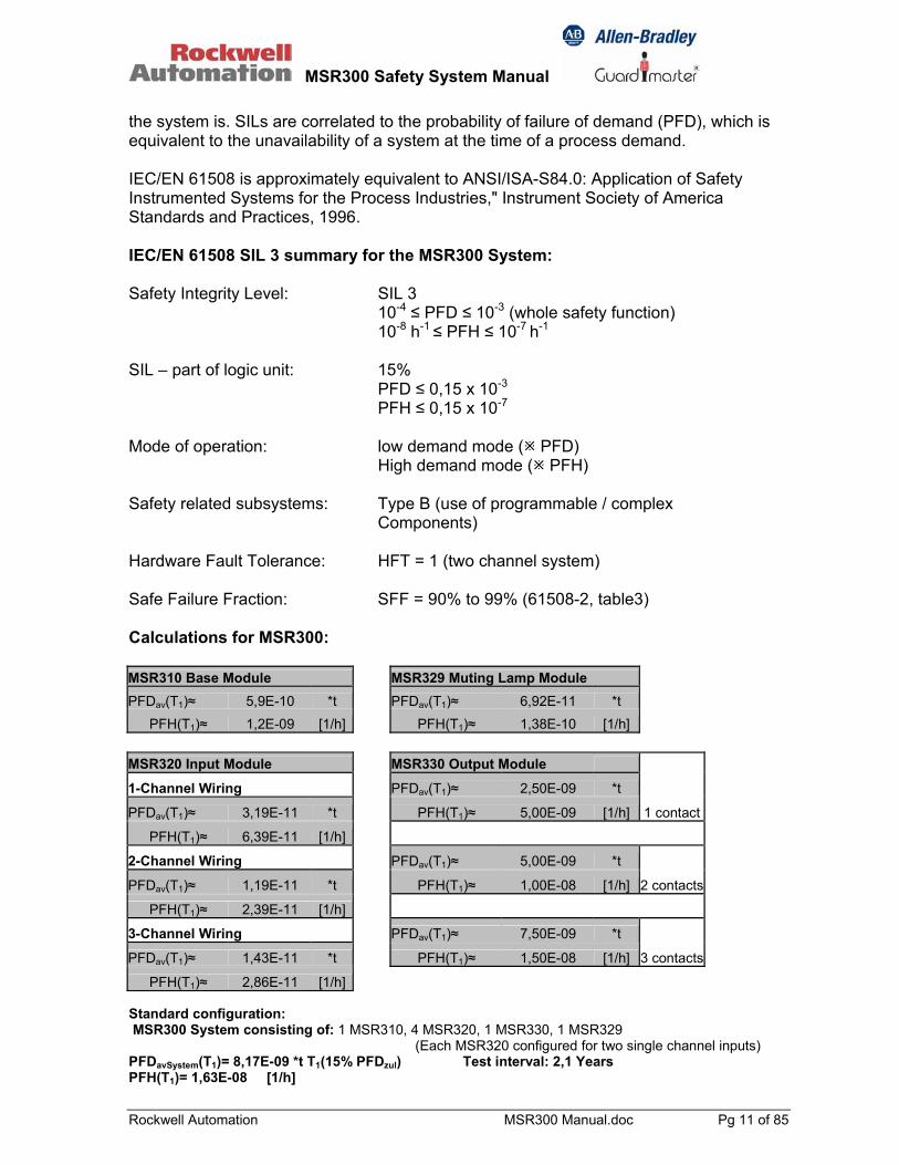
the system is. SILs are correlated to the probability of failure of demand (PFD), which is equivalent to the unavailability of a system at the time of a process demand. IEC/EN 61508 is approximately equivalent to ANSI/ISA-S84.0: Application of Safety Instrumented Systems for the Process Industries," Instrument Society of America Standards and Practices, 1996. IEC/EN 61508 SIL 3 summary for the MSR300 System: Safety Integrity Level: SIL 3 10-4 ≤ PFD ≤ 10-3 (whole safety function) 10-8 h-1 ≤ PFH ≤ 10-7 h-1 SIL – part of logic unit: 15% PFD ≤ 0,15 x 10⁻³ PFH ≤ 0,15 x 10⁻⁷ Mode of operation: low demand mode ( PFD) High demand mode ( PFH) Safety related subsystems: Type B (use of programmable / complex Components) Hardware Fault Tolerance: HFT = 1 (two channel system) Safe Failure Fraction: SFF = 90% to 99% (61508-2, table3) Calculations for MSR300: MSR310 Base Module MSR329 Muting Lamp Module
PFDav(T1)≈ 5,9E-10 *t PFDav(T1)≈ 6,92E-11 *t PFH(T1)≈ 1,2E-09 [1/h] PFH(T1)≈ 1,38E-10 [1/h]
MSR320 Input Module MSR330 Output Module
1-Channel Wiring PFDav(T1)≈ 2,50E-09 *t
PFDav(T1)≈ 3,19E-11 *t PFH(T1)≈ 5,00E-09 [1/h] 1 contact
PFH(T1)≈ 6,39E-11 [1/h]
2-Channel Wiring PFDav(T1)≈ 5,00E-09 *t
PFDav(T1)≈ 1,19E-11 *t PFH(T1)≈ 1,00E-08 [1/h] 2 contacts
PFH(T1)≈ 2,39E-11 [1/h]
3-Channel Wiring PFDav(T1)≈ 7,50E-09 *t
PFDav(T1)≈ 1,43E-11 *t PFH(T1)≈ 1,50E-08 [1/h] 3 contacts
PFH(T1)≈ 2,86E-11 [1/h] Standard configuration: MSR300 System consisting of: 1 MSR310, 4 MSR320, 1 MSR330, 1 MSR329
(Each MSR320 configured for two single channel inputs) PFDavSystem(T1)= 8,17E-09 *t T1(15% PFDzul) Test interval: 2,1 Years PFH(T1)= 1,63E-08 [1/h]

MSR300 Safety System Manual
Rockwell Automation MSR300 Manual.doc Pg 12 of 85
3.1.2 MSR300 Safety Relay Functions MSR300 Systems can be used for various safety relay functions outlined below, when appropriately configured for the respective function. Simultaneity monitoring (sometimes referred to as synchronization monitoring or coincidence gating) is often necessary for many of these safety applications. This means that 2 (sometimes even 3) input contacts must be closed (or reset) simultaneously to clear this set of inputs (simultaneity between all channels of one input). For these applications, the allowable time window is 3 seconds. Another common application that involves simultaneity monitoring (0.5 seconds window) is two-hand safety control. (simultaneity activation of both inputs of one module). 3.1.2.1 One-Channel Emergency Stop
• Safety output contacts are opened if the input loop is open. • Stop category: 0. • Short-circuiting of the input loop to electrical ground or 24V will be detected.
3.1.2.2 Two-Channel Emergency Stop
• Safety output contacts are opened if at least one input loop is open. • Stop category: 0. • Short-circuiting of the input loop to electrical ground or 24V will be detected. • Cross loops will be detected. • Suitable for use with safety mats. • Can be configured for simultaneity detection: 3 seconds limit.
3.1.2.3 Three-Channel Emergency Stop
• Safety output contacts are opened if at least one input loop is open. • Stop category: 0. • Short-circuiting of the input loop to electrical ground or 24V will be detected. • Cross loops will be detected. • Can be configured for simultaneity detection: 3 seconds limit.
3.1.2.4 Two-Channel Safety Gates
• Safety output contacts are opened if the N/O input is closed or the N/C input is open
• Stop category: 0. • Short-circuiting of the input loop to electrical ground or 24V will be detected. • Cross loops will be detected. • Can be configured for simultaneity detection: 3 seconds limit. • Can be configured to execute a start-up test of the input loops.
3.1.2.5 Two-Channel Light Curtain
• Safety output contacts are opened if one or more inputs have has no signal. • Stop category: 0.
MSR300 Safety System Manual
Rockwell Automation MSR300 Manual.doc Pg 13 of 85
3.1.2.6 Two-Hand Control
• Two-hand control type IIIC (EN 574) • Simultaneity detection: 0.5 seconds limit.
The two-hand control function ensures that operators keep their hands clear of a hazardous area of a machine. It is meant for use with machines such as mechanical and hydraulic presses. A machine cycle can only be initiated by pressing two momentary pushbutton switches simultaneously. Switches must fulfill the requirements of EN574 type IIIC. Releasing one or both pushbutton switches open the output contacts to interrupt the cycle and stop the machine. The output contacts can be closed again only after the inputs have released and the pushbutton switches actuated again. If a machine is operated by more than one person simultaneously, separate two-hand controls are required for each operator station. The two-hand operator station should be located far enough from the hazardous area so that the latter cannot be reached by the operator before the machine stops (after a stop command is given). Typical applications of two-hand safety controls are: presses, shears, plastic-molding machines, etc. 3.1.2.7 Reset Action The reset logic of the three Output Groups of the system can be configured for one of the following modes:
• Automatic reset: The Output Group is active as soon as all input circuits and feedback loop are closed.
• Manual monitored reset: The Output Group is not active until the reset button has been operated and then released (and feedback loop closed). This eliminates the possibility of triggering automatic activation if the reset switch is overridden.
• Manual (non-monitored) reset: The Output Group can be set up for automatic reset and yet have a reset contact connected in series with the feedback loop. In this case manual reset is not monitored.
3.1.2.8 Muting (for Robot cell applications) Muting is the safe, automatic and temporary suspension of an electrosensitive protective device, in accordance with EN 61496-1 A.7. Muting is typically applied to allow material in process to be moved into and out of a hazardous area. The presence / movement of such material can be detected by muting sensors. Typically, muting causes the signal inputs from safety barriers such as opto-switches or light curtains to be temporarily ignored, - only as long as the muting sensors detect material in process approaching entry to, or exit from a machine. MSR300 muting does not monitor material flow but is especially designed and limited to applications as explained in the Robot cell examples later in this document (safe position monitoring of the Robot arm).
MSR300 Safety System Manual
Rockwell Automation MSR300 Manual.doc Pg 14 of 85
Muting lamps are deployed to indicate that muting is existent. Special safety controls are necessary to ensure that muting lamps operate correctly and safely. The MSR329 Muting Lamp Controller is expressly designed for this purpose. Details of this module are given later in this document. 3.2 MSR300 System: Overview The MSR300 System is a modular safety control system with extended functions, and is intended for monitoring and safety control of:
• 1-, 2-, or 3-channel emergency stops • Safety gates and doors • Light curtains • Safety mats • Two-hand control
An MSR300 System is made up of a combination of the following MSR300 Series Modules:
• MSR310 Base Module • MSR320 Input Module • MSR330 Output Module • MSR329 Muting Lamp Module:
An MSR300 System is constituted as follows:
• One MSR310 Base Module • At least one MSR320 Input Module • At least one MSR330 Output Module • One MSR329 Muting Modules may be optionally included if needed (provided one
MSR320 Input Module is configured for the robot function). MSR320 and MSR329 Modules are daisy-chain connected to the left bus interface connector of the MSR310 Base Module. Up to ten MSR 320 Input Modules can be included in an MSR300 System, for a maximum of 20 input circuits. MSR330 Output Modules are daisy-chain connected to the right bus interface connector of the MSR310 Base Module. Up to six MSR330 Output Modules can be included in an MSR300 System, for a maximum of 18 N/O safety outputs plus 6 N/C auxiliary outputs. The integrity of all safety inputs are constantly checked by means of feedback of the safety loops. Dynamic (pulse frequency) excitation signals are generated by the MSR310 Base Module. These signals are fed (as a star-connected bus) to monitor the contact(s) of every safety sensing device connected to the MSR 300 System. The signals are then feed back to the Input Module to which each corresponding safety contact input is connected. If a safety-sensing device is defective the system will detect non-valid signals or signal sequences on the Inputs. This causes a fail-safe fault response by the MSR300 System. Every input can be connected to a separate input switching circuit. Input modules can be freely assigned to any output group module.
MSR300 Safety System Manual
Rockwell Automation MSR300 Manual.doc Pg 15 of 85
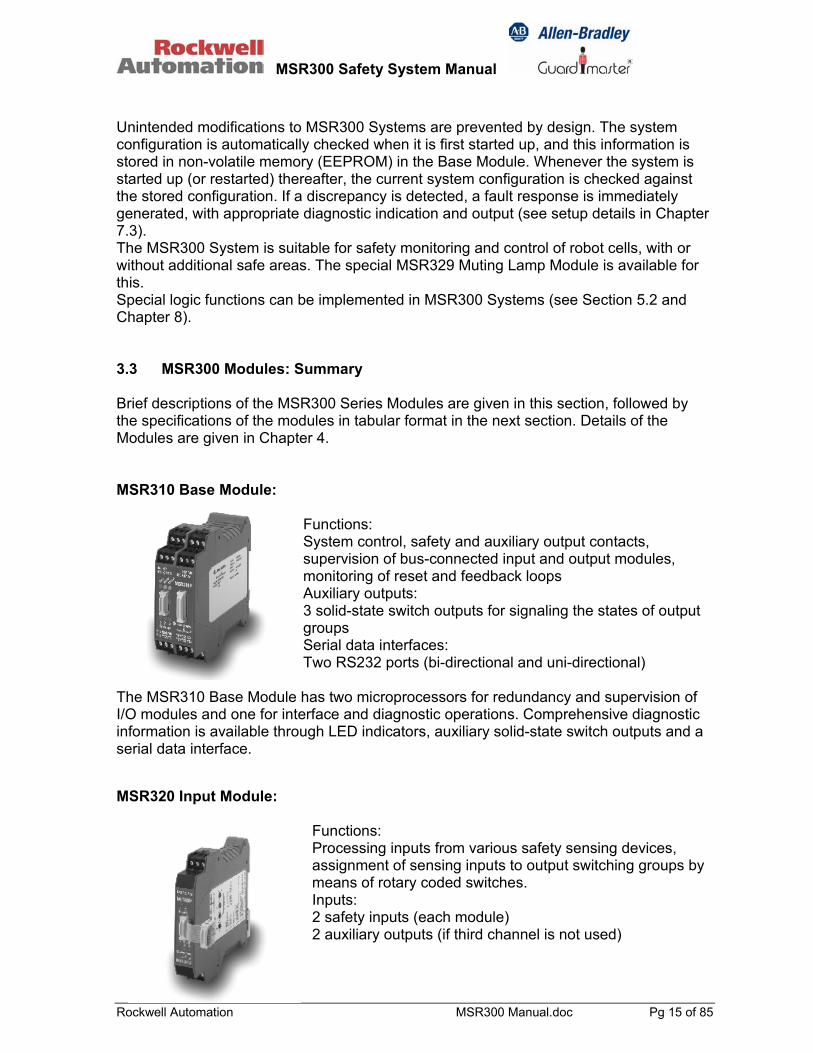
Unintended modifications to MSR300 Systems are prevented by design. The system configuration is automatically checked when it is first started up, and this information is stored in non-volatile memory (EEPROM) in the Base Module. Whenever the system is started up (or restarted) thereafter, the current system configuration is checked against the stored configuration. If a discrepancy is detected, a fault response is immediately generated, with appropriate diagnostic indication and output (see setup details in Chapter 7.3). The MSR300 System is suitable for safety monitoring and control of robot cells, with or without additional safe areas. The special MSR329 Muting Lamp Module is available for this. Special logic functions can be implemented in MSR300 Systems (see Section 5.2 and Chapter 8). 3.3 MSR300 Modules: Summary Brief descriptions of the MSR300 Series Modules are given in this section, followed by the specifications of the modules in tabular format in the next section. Details of the Modules are given in Chapter 4. MSR310 Base Module:
Functions: System control, safety and auxiliary output contacts, supervision of bus-connected input and output modules, monitoring of reset and feedback loops Auxiliary outputs: 3 solid-state switch outputs for signaling the states of output groups Serial data interfaces: Two RS232 ports (bi-directional and uni-directional)
The MSR310 Base Module has two microprocessors for redundancy and supervision of I/O modules and one for interface and diagnostic operations. Comprehensive diagnostic information is available through LED indicators, auxiliary solid-state switch outputs and a serial data interface. MSR320 Input Module:
Functions: Processing inputs from various safety sensing devices, assignment of sensing inputs to output switching groups by means of rotary coded switches. Inputs: 2 safety inputs (each module) 2 auxiliary outputs (if third channel is not used)
MSR300 Safety System Manual
Rockwell Automation MSR300 Manual.doc Pg 16 of 85
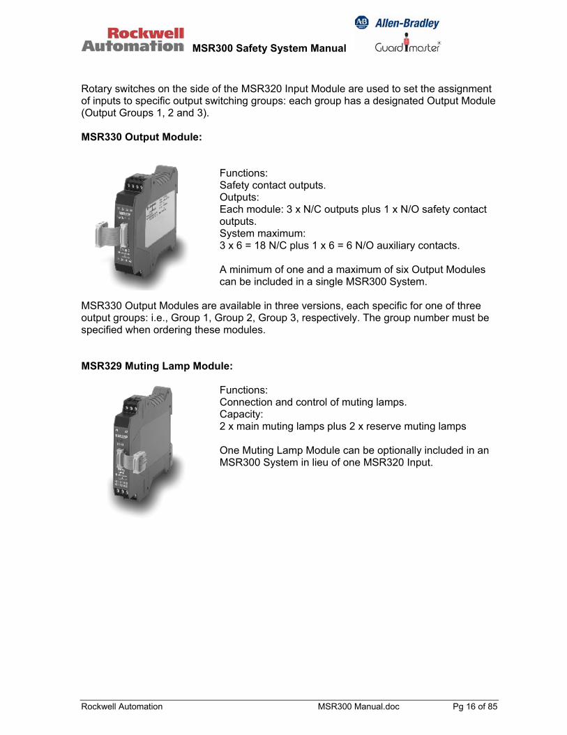
Rotary switches on the side of the MSR320 Input Module are used to set the assignment of inputs to specific output switching groups: each group has a designated Output Module (Output Groups 1, 2 and 3). MSR330 Output Module:
Functions: Safety contact outputs. Outputs: Each module: 3 x N/C outputs plus 1 x N/O safety contact outputs. System maximum: 3 x 6 = 18 N/C plus 1 x 6 = 6 N/O auxiliary contacts. A minimum of one and a maximum of six Output Modules can be included in a single MSR300 System.
MSR330 Output Modules are available in three versions, each specific for one of three output groups: i.e., Group 1, Group 2, Group 3, respectively. The group number must be specified when ordering these modules. MSR329 Muting Lamp Module:
Functions: Connection and control of muting lamps. Capacity: 2 x main muting lamps plus 2 x reserve muting lamps One Muting Lamp Module can be optionally included in an MSR300 System in lieu of one MSR320 Input.
MSR300 Safety System Manual
Rockwell Automation MSR300 Manual.doc Pg 17 of 85
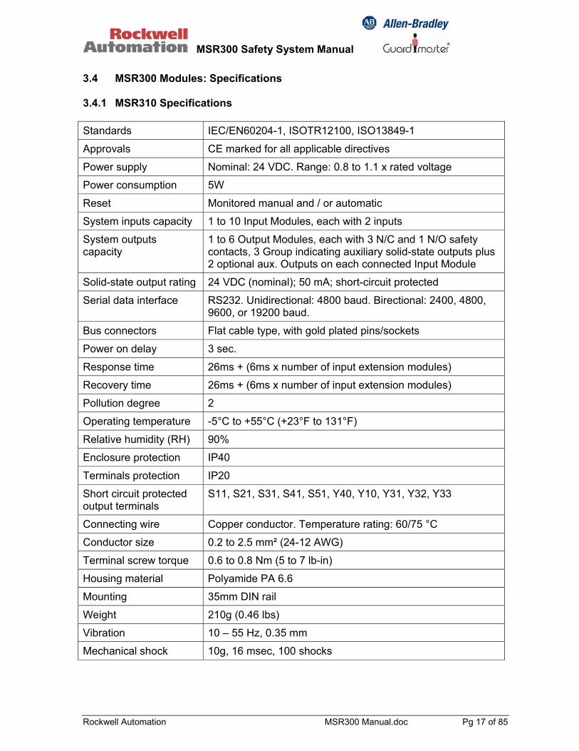
3.4 MSR300 Modules: Specifications 3.4.1 MSR310 Specifications Standards IEC/EN60204-1, ISOTR12100, ISO13849-1
Approvals CE marked for all applicable directives
Power supply Nominal: 24 VDC. Range: 0.8 to 1.1 x rated voltage
Power consumption 5W
Reset Monitored manual and / or automatic
System inputs capacity 1 to 10 Input Modules, each with 2 inputs
System outputs capacity
1 to 6 Output Modules, each with 3 N/C and 1 N/O safety contacts, 3 Group indicating auxiliary solid-state outputs plus 2 optional aux. Outputs on each connected Input Module
Solid-state output rating 24 VDC (nominal); 50 mA; short-circuit protected
Serial data interface RS232. Unidirectional: 4800 baud. Birectional: 2400, 4800, 9600, or 19200 baud.
Bus connectors Flat cable type, with gold plated pins/sockets
Power on delay 3 sec.
Response time 26ms + (6ms x number of input extension modules)
Recovery time 26ms + (6ms x number of input extension modules)
Pollution degree 2
Operating temperature -5°C to +55°C (+23°F to 131°F)
Relative humidity (RH) 90%
Enclosure protection IP40
Terminals protection IP20
Short circuit protected output terminals
S11, S21, S31, S41, S51, Y40, Y10, Y31, Y32, Y33
Connecting wire Copper conductor. Temperature rating: 60/75 °C
Conductor size 0.2 to 2.5 mm² (24-12 AWG)
Terminal screw torque 0.6 to 0.8 Nm (5 to 7 lb-in)
Housing material Polyamide PA 6.6
Mounting 35mm DIN rail
Weight 210g (0.46 lbs)
Vibration 10 – 55 Hz, 0.35 mm
Mechanical shock 10g, 16 msec, 100 shocks

MSR300 Safety System Manual
Rockwell Automation MSR300 Manual.doc Pg 18 of 85
3.4.2 MSR320 Specifications Standards IEC/EN60204-1, ISOTR12100, ISO13849-1
Approvals CE marked for all applicable directives
Power supply Nominal: 24 VDC. Range: 0.8 to 1.1 x rated voltage
Power consumption approx. 3W
Safety inputs 1 N/C, 2 N/C, 3 N/C, safety mat, light curtain, N/C-N/O, two-hand control
Solid-state switch output rating
24 VDC (nominal); 20 mA; short-circuit protected
Input simultaneity detection
3 secs. or disabled (infinite time limit) Two Hand Operation Mode: 0.5s between both Inputs
LED indicators Input status (2): Green = input closed. Red = input open Output switch group assignment (3)
Input load impedance 900 ohms (max.)
Bus connectors Flat cable type, with gold plated pins/sockets
Pollution degree 2
Operating temperature -5°C to +55°C (+23°F to 131°F)
Relative humidity (RH) 90%
Enclosure protection IP40
Terminals protection IP20
Conductor size 0.2 to 2.5 mm² (24-12 AWG)
Terminal screw torque 0.6 to 0.8 Nm (5 to 7 lb-in)
Housing material Polyamide PA 6.6
Mounting 35mm DIN rail
Weight 110g (0.24 lbs)
Vibration 10 – 55 Hz, 0.35 mm
Mechanical shock 10g, 16 msec, 100 shocks
MSR300 Safety System Manual
Rockwell Automation MSR300 Manual.doc Pg 19 of 85
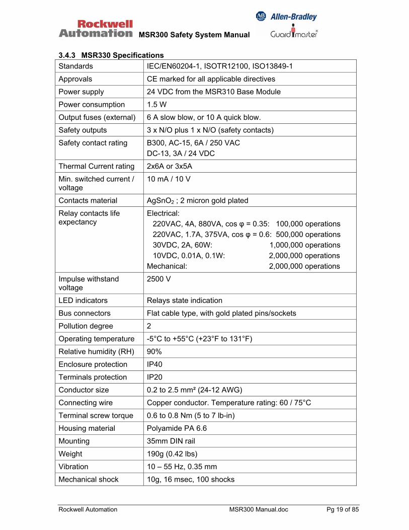
3.4.3 MSR330 Specifications Standards IEC/EN60204-1, ISOTR12100, ISO13849-1
Approvals CE marked for all applicable directives
Power supply 24 VDC from the MSR310 Base Module
Power consumption 1.5 W
Output fuses (external) 6 A slow blow, or 10 A quick blow.
Safety outputs 3 x N/O plus 1 x N/O (safety contacts)
Safety contact rating B300, AC-15, 6A / 250 VAC DC-13, 3A / 24 VDC
Thermal Current rating 2x6A or 3x5A
Min. switched current / voltage
10 mA / 10 V
Contacts material AgSnO2 ; 2 micron gold plated
Relay contacts life expectancy
Electrical: 220VAC, 4A, 880VA, cos φ = 0.35: 100,000 operations 220VAC, 1.7A, 375VA, cos φ = 0.6: 500,000 operations 30VDC, 2A, 60W: 1,000,000 operations 10VDC, 0.01A, 0.1W: 2,000,000 operations Mechanical: 2,000,000 operations
Impulse withstand voltage
2500 V
LED indicators Relays state indication
Bus connectors Flat cable type, with gold plated pins/sockets
Pollution degree 2
Operating temperature -5°C to +55°C (+23°F to 131°F)
Relative humidity (RH) 90%
Enclosure protection IP40
Terminals protection IP20
Conductor size 0.2 to 2.5 mm² (24-12 AWG)
Connecting wire Copper conductor. Temperature rating: 60 / 75°C
Terminal screw torque 0.6 to 0.8 Nm (5 to 7 lb-in)
Housing material Polyamide PA 6.6
Mounting 35mm DIN rail
Weight 190g (0.42 lbs)
Vibration 10 – 55 Hz, 0.35 mm
Mechanical shock 10g, 16 msec, 100 shocks

MSR300 Safety System Manual
Rockwell Automation MSR300 Manual.doc Pg 20 of 85
3.4.4 MSR329 Specifications Standards IEC/EN60204-1, ISOTR12100, ISO13849-1
Approvals CE marked for all applicable directives
Power supply Nominal: 24 VDC. Range: 0.8 to 1.1 x rated voltage
Power consumption 1 W
Inputs Monitoring of 2 muting lamps, 30 mA - 200 mA each
Outputs 2 x muting lamps, plus 2 x reserve muting lamps
LED indicators State of muting lamps
Bus connectors Flat cable type, with gold plated pins/sockets
Pollution degree 2
Operating temperature -5°C to +55°C (+23°F to 131°F)
Relative humidity (RH) 90%
Enclosure protection IP40
Terminal protection IP20
Conductor size 0.2 to 2.5mm² (24-12 AWG)
Terminal screw torque 0.6 to 0.8 Nm (5 to 7 lb-in)
Housing material Polyamide PA 6.6
Mounting 35mm DIN rail
Weight 190g (0.42 lbs)
Vibration 10 – 55 Hz, 0.35 mm
Mechanical shock 10g, 16 msec, 100 shocks
MSR300 Safety System Manual
Rockwell Automation MSR300 Manual.doc Pg 21 of 85
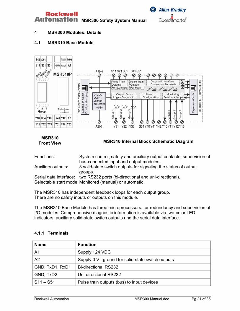
4 MSR300 Modules: Details 4.1 MSR310 Base Module
Functions: System control, safety and auxiliary output contacts, supervision of
bus-connected input and output modules. Auxiliary outputs: 3 solid-state switch outputs for signaling the states of output
groups. Serial data interface: two RS232 ports (bi-directional and uni-directional). Selectable start mode: Monitored (manual) or automatic. The MSR310 has independent feedback loops for each output group. There are no safety inputs or outputs on this module. The MSR310 Base Module has three microprocessors: for redundancy and supervision of I/O modules. Comprehensive diagnostic information is available via two-color LED indicators, auxiliary solid-state switch outputs and the serial data interface. 4.1.1 Terminals Name Function A1 Supply +24 VDC
A2 Supply 0 V ; ground for solid-state switch outputs
GND, TxD1, RxD1 Bi-directional RS232
GND, TxD2 Uni-directional RS232
S11 – S51 Pulse train outputs (bus) to input devices
MSR310 Internal Block Schematic Diagram MSR310
Front View
MSR300 Safety System Manual
Rockwell Automation MSR300 Manual.doc Pg 22 of 85
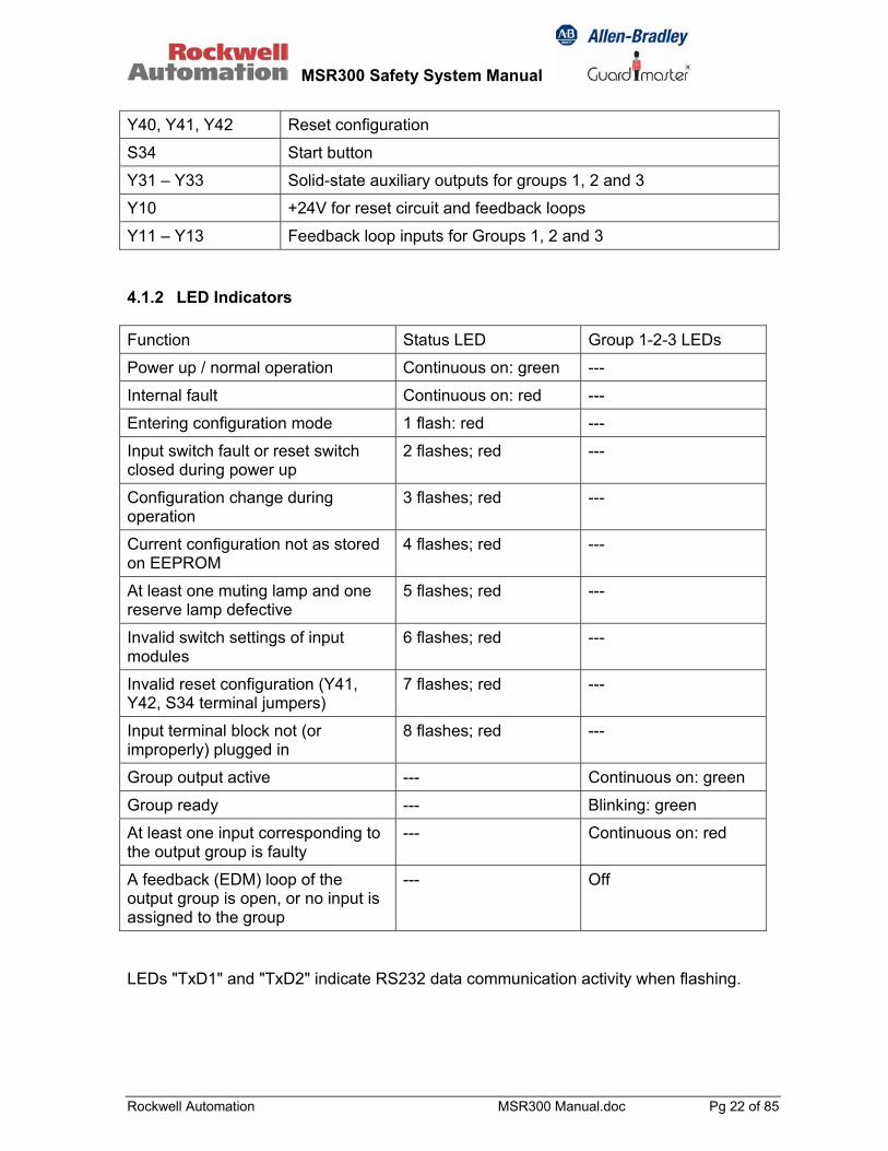
Y40, Y41, Y42 Reset configuration
S34 Start button
Y31 – Y33 Solid-state auxiliary outputs for groups 1, 2 and 3
Y10 +24V for reset circuit and feedback loops
Y11 – Y13 Feedback loop inputs for Groups 1, 2 and 3 4.1.2 LED Indicators Function Status LED Group 1-2-3 LEDs
Power up / normal operation Continuous on: green ---
Internal fault Continuous on: red ---
Entering configuration mode 1 flash: red ---
Input switch fault or reset switch closed during power up
2 flashes; red ---
Configuration change during operation
3 flashes; red ---
Current configuration not as stored on EEPROM
4 flashes; red ---
At least one muting lamp and one reserve lamp defective
5 flashes; red ---
Invalid switch settings of input modules
6 flashes; red ---
Invalid reset configuration (Y41, Y42, S34 terminal jumpers)
7 flashes; red ---
Input terminal block not (or improperly) plugged in
8 flashes; red ---
Group output active --- Continuous on: green
Group ready --- Blinking: green
At least one input corresponding to the output group is faulty
--- Continuous on: red
A feedback (EDM) loop of the output group is open, or no input is assigned to the group
--- Off
LEDs "TxD1" and "TxD2" indicate RS232 data communication activity when flashing.
MSR300 Safety System Manual
Rockwell Automation MSR300 Manual.doc Pg 23 of 85
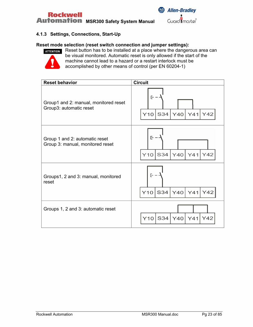
4.1.3 Settings, Connections, Start-Up Reset mode selection (reset switch connection and jumper settings):
Reset button has to be installed at a place where the dangerous area can be visual monitored. Automatic reset is only allowed if the start of the machine cannot lead to a hazard or a restart interlock must be accomplished by other means of control (per EN 60204-1)
Reset behavior Circuit
Group1 and 2: manual, monitored reset Group3: automatic reset
Group 1 and 2: automatic reset Group 3: manual, monitored reset Groups1, 2 and 3: manual, monitored reset Groups 1, 2 and 3: automatic reset

MSR300 Safety System Manual
Rockwell Automation MSR300 Manual.doc Pg 24 of 85
4.1.4 Auxiliary Outputs (Solid-State Switches) The MSR310 Base Module has three LEDs and three auxiliary (solid-state switch) outputs that indicate the states of the three Output Groups, respectively.
Condition Y31 Y32 Y33 Group 1 active 24V --- --- Group 1 inactive 0V --- --- Group 2 active --- 24V --- Group 2 inactive --- 0V --- Group 3 active --- --- 24V Group 3 inactive --- --- 0V
Wiring
These outputs are short-circuit protected. Current limit: 50 mA.
MSR300 Safety System Manual
Rockwell Automation MSR300 Manual.doc Pg 25 of 85
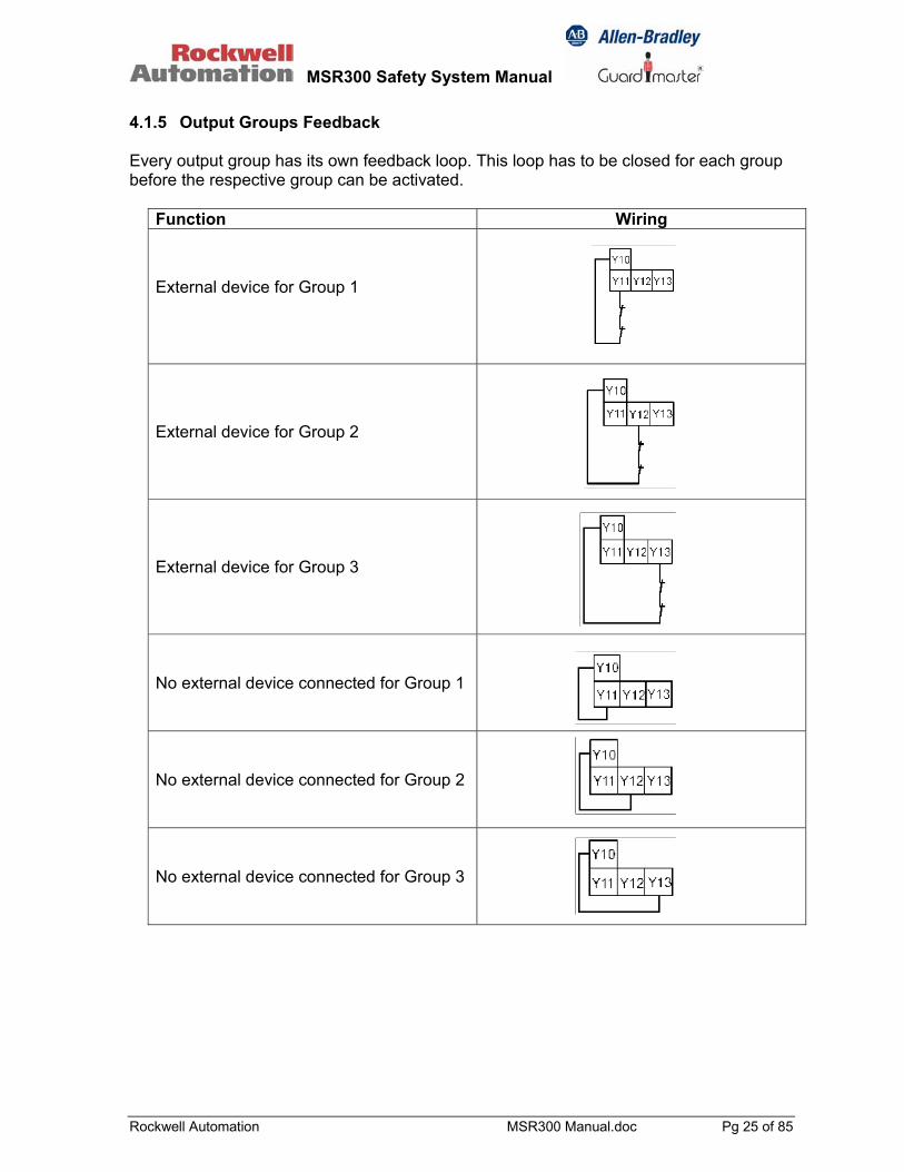
4.1.5 Output Groups Feedback Every output group has its own feedback loop. This loop has to be closed for each group before the respective group can be activated.
Function Wiring
External device for Group 1
External device for Group 2
External device for Group 3
No external device connected for Group 1
No external device connected for Group 2
No external device connected for Group 3

MSR300 Safety System Manual
Rockwell Automation MSR300 Manual.doc Pg 26 of 85
4.1.6 Input Fault Logging If inputs are wired for simultaneity monitoring, the following events are registered as faults and stored in EEPROM:
• Simultaneity time limit is exceeded. • Not all channels change state as required if input is cycled • The reset switch is closed while not all channels of at least one input are in the
correct state for either “on” or “off”.
The faults can be cleared by opening and closing the circuits of all channels of one input simultaneously. If the faults are not cleared, the MSR310 indicates this on the next power up. The faults can even then be cleared by opening and closing the circuits of all channels of the faulty input simultaneously. 4.1.7 Serial Communication Interface Connections The MSR310 is equipped with two RS232 serial data interfaces: one for bi-directional and one for uni-directional communication mode. The interface connections are illustrated below.
TxD1RxD1GND
RS-232Bi-
directional
TxD2
GND
RS-232Uni-directional
Serial data communication protocol details (uni-directional and bi-directional) are given in Chapter 9, at the end of this document.

MSR300 Safety System Manual
Rockwell Automation MSR300 Manual.doc Pg 27 of 85
4.2 MSR320 Input Module Functions: Processing inputs from various safety sensing devices.
Assignment of sensing inputs to output switching groups by means of redundant rotary coded switches: one set selects the input function, the other set selects the output group.
Inputs: 2 inputs for single-, dual- or three-channel activation. A solid-state switch on-off signal input from a light curtain and an
on-off signal input from safety contacts (switch or electromechanical relay) input can be given as inputs to the same Input Module.
Rotary switches on the right side of the MSR320 Input Module. One rotary switch selects the function of the Input Module (see functions list below), the other assigns an Output Group (Module) assigned to this Input Module.
MSR320 Rotary Switches & Settings (Located on right side of the module)
MSR320 Front View
Two switches per selection have been provided for redundancy. Both sets of rotary switches of one input module must be set identically.
MSR300 Safety System Manual
Rockwell Automation MSR300 Manual.doc Pg 28 of 85
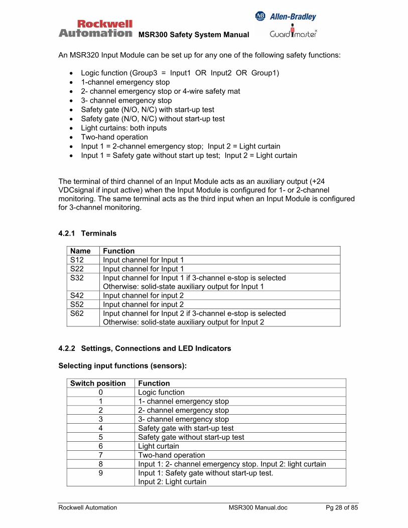
An MSR320 Input Module can be set up for any one of the following safety functions:
• Logic function (Group3 = Input1 OR Input2 OR Group1) • 1-channel emergency stop • 2- channel emergency stop or 4-wire safety mat • 3- channel emergency stop • Safety gate (N/O, N/C) with start-up test • Safety gate (N/O, N/C) without start-up test • Light curtains: both inputs • Two-hand operation • Input 1 = 2-channel emergency stop; Input 2 = Light curtain • Input 1 = Safety gate without start up test; Input 2 = Light curtain
The terminal of third channel of an Input Module acts as an auxiliary output (+24 VDCsignal if input active) when the Input Module is configured for 1- or 2-channel monitoring. The same terminal acts as the third input when an Input Module is configured for 3-channel monitoring. 4.2.1 Terminals
Name Function S12 Input channel for Input 1 S22 Input channel for Input 1 S32 Input channel for Input 1 if 3-channel e-stop is selected
Otherwise: solid-state auxiliary output for Input 1 S42 Input channel for input 2 S52 Input channel for input 2 S62 Input channel for Input 2 if 3-channel e-stop is selected
Otherwise: solid-state auxiliary output for Input 2 4.2.2 Settings, Connections and LED Indicators Selecting input functions (sensors):
Switch position Function 0 Logic function 1 1- channel emergency stop 2 2- channel emergency stop 3 3- channel emergency stop 4 Safety gate with start-up test 5 Safety gate without start-up test 6 Light curtain 7 Two-hand operation 8 Input 1: 2- channel emergency stop. Input 2: light curtain 9 Input 1: Safety gate without start-up test.
Input 2: Light curtain
MSR300 Safety System Manual
Rockwell Automation MSR300 Manual.doc Pg 29 of 85
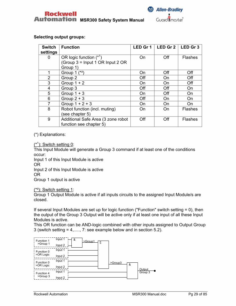
Selecting output groups:
Switch settings
Function LED Gr 1 LED Gr 2 LED Gr 3
0 OR logic function (*1) (Group 3 = Input 1 OR Input 2 OR Group 1)
On Off Flashes
1 Group 1 (*²) On Off Off 2 Group 2 Off On Off 3 Group 1 + 2 On On Off 4 Group 3 Off Off On 5 Group 1 + 3 On Off On 6 Group 2 + 3 Off On On 7 Group 1 + 2 + 3 On On On 8 Robot function (incl. muting)
(see chapter 5) On On Flashes
9 Additional Safe Area (3 zone robot function see chapter 5)
Off Off Flashes
(*) Explanations: (*1): Switch setting 0: This Input Module will generate a Group 3 command if at least one of the conditions occur: Input 1 of this Input Module is active OR Input 2 of this Input Module is active OR Group 1 output is active (*²): Switch setting 1: Group 1 Output Module is active if all inputs circuits to the assigned Input Module/s are closed. If several Input Modules are set up for logic function ("Function" switch setting = 0), then the output of the Group 3 Output will be active only if at least one input of all these Input Modules is active. This OR function can be AND-logic combined with other inputs assigned to Output Group 3 (switch setting = 4,....., 7: see example below and in section 5.2).
&OutputGroup 3
>Group1&
Input 1
>=
Input 2
>Group3 Input 1
Input 2 Input 1
Input 2
Input 1
Input 2Function 1
>Group 1
Function 0>OR Logic
Function 0>OR Logic
Function 4>Group 3

MSR300 Safety System Manual
Rockwell Automation MSR300 Manual.doc Pg 30 of 85
LED indication of Output Group assignment: The Input Module has three LEDs for indicating its assigned Output Group Module. The Input Module has two additional LEDs that give diagnostic information as follows:
States Function LED Input 1 LED Input 2 1 Input 1 valid Continuous green --- 2 Input 1 invalid Continuous red --- 3 Input 1 switch faulty Flashes red --- 4 Input 2 valid --- Continuous green 5 Input 2 invalid --- Continuous red 6 Input 2 switch faulty --- Flashes red 7 Detected configuration
does not match that stored in the EEPROM
Input 1 LED flashes red alternately with
Input 2 LED
Input 2 LED flashes red alternately with
Input 1 LED
8 Redundant rotary switches are not set identically.
Input 1 LED flashes red alternate with
Input 2 LED
Input 2 LED flashes red alternate with
Input 1 LED 4.2.3 Connections For Input Functions 4.2.3.1 1-Channel Emergency Stop Switch setting: 1 Input 1 Input 2 Solid-state auxiliary
output: Input 1 Solid-state auxiliary output: Input 2
S11-S12: N/C S11-S42: N/C S32 S62
Switches with forced driven contacts and additional failure exclusions related e.g. to wiring and crossfaults required to achieve safety cat 4 in this application (e.g. installation and wiring in IP54 cabinet)
MSR300 Safety System Manual
Rockwell Automation MSR300 Manual.doc Pg 31 of 85
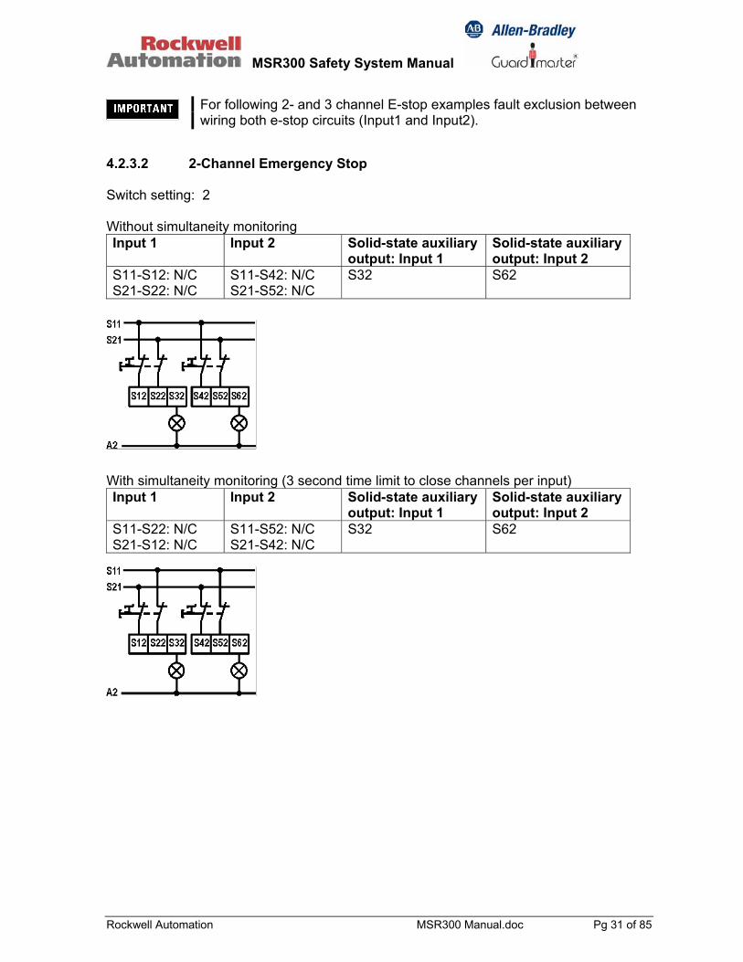
4.2.3.2 2-Channel Emergency Stop Switch setting: 2 Without simultaneity monitoring Input 1 Input 2 Solid-state auxiliary
output: Input 1 Solid-state auxiliary output: Input 2
S11-S12: N/C S21-S22: N/C
S11-S42: N/C S21-S52: N/C
S32 S62
With simultaneity monitoring (3 second time limit to close channels per input) Input 1 Input 2 Solid-state auxiliary
output: Input 1 Solid-state auxiliary output: Input 2
S11-S22: N/C S21-S12: N/C
S11-S52: N/C S21-S42: N/C
S32 S62
For following 2- and 3 channel E-stop examples fault exclusion between wiring both e-stop circuits (Input1 and Input2).

MSR300 Safety System Manual
Rockwell Automation MSR300 Manual.doc Pg 32 of 85
4.2.3.3 3-Channel Emergency Stop Switch setting: 3 Without simultaneity monitoring. Input 1 Input 2 Solid-state auxiliary
output: Input 1 Solid-state auxiliary output: Input 2
S11-S12: N/C S21-S22: N/C S31-S32: N/C
S11-S42: N/C S21-S52: N/C S31-S62: N/C
Not available Not available
With simultaneity monitoring (3 second limit). Input 1 Input 2 Solid-state auxiliary
output: Input 1 Solid-state auxiliary output: Input 2
S11-S22: N/C S21-S12: N/C S31-S32: N/C
S11-S52: N/C S21-S42: N/C S31-S62: N/C
Not available Not available
4.2.3.4 Safety Mats Switch setting: 2 Without simultaneity monitoring. Input 1 Input 2 Solid-state auxiliary
output: Input 1 Solid-state auxiliary output: Input 2
S41-S12: N/C S51-S22: N/C
S41-S42: N/C S51-S52: N/C
S32 S62
Note: if more than a single input is connected to Safety Mats it is recommended to install two diodes in series to the input wires of each mat. This avoids crossfault-feedback to S41 and S51 and is required to achieve individual annunciation on each input.
MSR300 Safety System Manual
Rockwell Automation MSR300 Manual.doc Pg 33 of 85
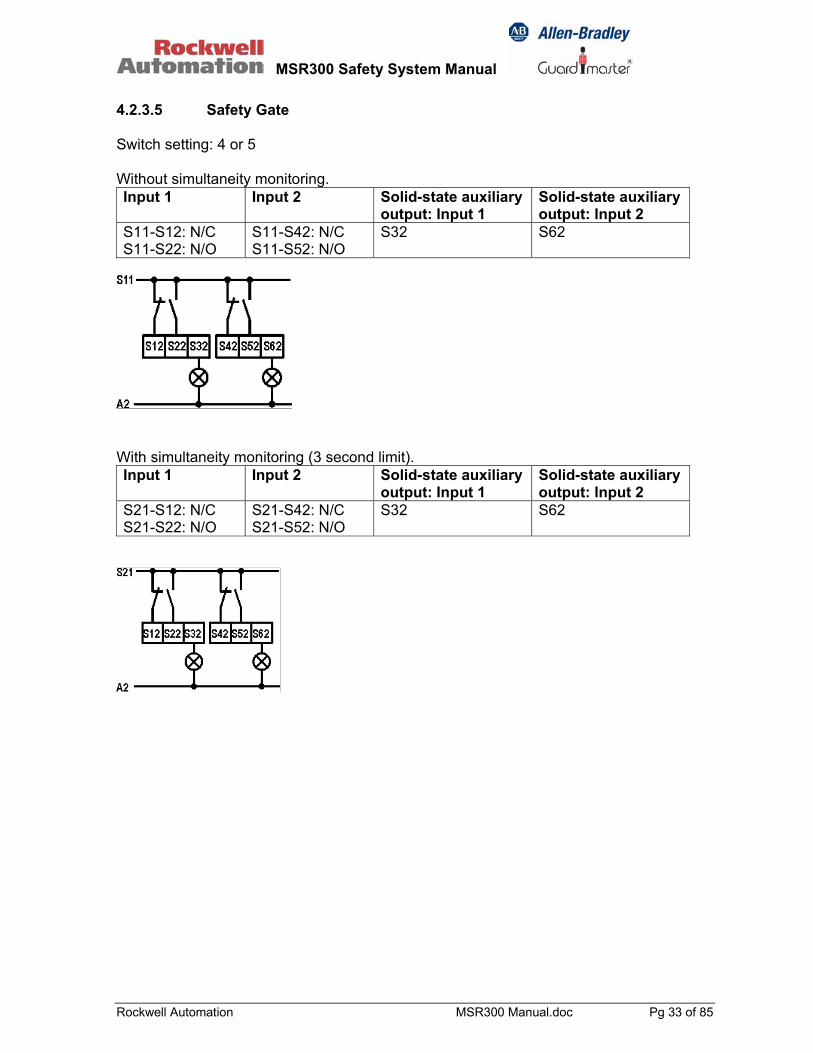
4.2.3.5 Safety Gate Switch setting: 4 or 5 Without simultaneity monitoring. Input 1 Input 2 Solid-state auxiliary
output: Input 1 Solid-state auxiliary output: Input 2
S11-S12: N/C S11-S22: N/O
S11-S42: N/C S11-S52: N/O
S32 S62
With simultaneity monitoring (3 second limit). Input 1 Input 2 Solid-state auxiliary
output: Input 1 Solid-state auxiliary output: Input 2
S21-S12: N/C S21-S22: N/O
S21-S42: N/C S21-S52: N/O
S32 S62
MSR300 Safety System Manual
Rockwell Automation MSR300 Manual.doc Pg 34 of 85
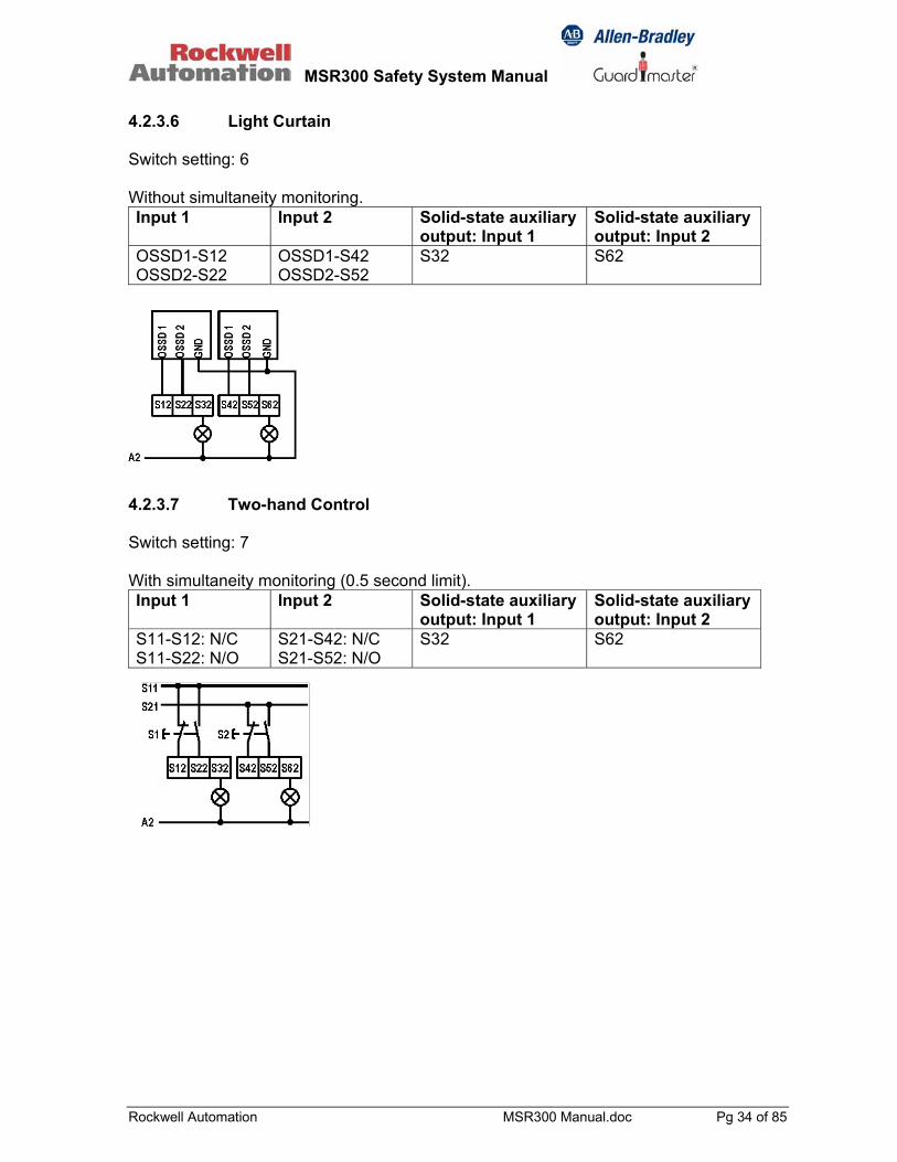
4.2.3.6 Light Curtain Switch setting: 6 Without simultaneity monitoring. Input 1 Input 2 Solid-state auxiliary
output: Input 1 Solid-state auxiliary output: Input 2
OSSD1-S12 OSSD2-S22
OSSD1-S42 OSSD2-S52
S32 S62
4.2.3.7 Two-hand Control Switch setting: 7 With simultaneity monitoring (0.5 second limit). Input 1 Input 2 Solid-state auxiliary
output: Input 1 Solid-state auxiliary output: Input 2
S11-S12: N/C S11-S22: N/O
S21-S42: N/C S21-S52: N/O
S32 S62

MSR300 Safety System Manual
Rockwell Automation MSR300 Manual.doc Pg 35 of 85
4.2.3.8 2-Channel Emergency Stop and Light Curtain Switch setting: 8 Without simultaneity monitoring of Input 1 and Input 2. Input 1 Input 2 Solid-state auxiliary
output: Input 1 Solid-state auxiliary output: Input 2
S11-S12: N/C S21-S22: N/C
OSSD1-S42 OSSD2-S52
S32 S62
With simultaneity monitoring (3 second limit) of Input 1 Input 1 Input 2 Solid-state auxiliary
output: Input 1 Solid-state auxiliary output: Input 2
S11-S12: N/C S21-S22: N/C
OSSD1-S42 OSSD2-S52
S32 S62

MSR300 Safety System Manual
Rockwell Automation MSR300 Manual.doc Pg 36 of 85
4.2.3.9 Safety Gate and Light Curtain Switch setting: 9 Without simultaneity monitoring of Input 1 and Input 2. Input 1 Input 2 Solid-state auxiliary
output: Input 1 Solid-state auxiliary output: Input 2
S11-S12: N/C S11-S22: N/O
OSSD1-S42 OSSD2-S52
S32 S62
With simultaneity monitoring (3 second limit) of Input 1 and without simultaneity monitoring of Input 2. Input 1 Input 2 Solid-state auxiliary
output: Input 1 Solid-state auxiliary output: Input 2
S21-S12: N/C S21-S22: N/O
OSSD1-S42 OSSD2-S52
S32 S62
See respective wiring diagrams for safety door and light curtain (above).

MSR300 Safety System Manual
Rockwell Automation MSR300 Manual.doc Pg 37 of 85
4.3 MSR330 Output Module
13 23 33 41
14 24 34 42
Group 1
13 23 33 41
14 24 34 42
Group 2
13 23 33 41
14 24 34 42
Group 3
MSR330 Modules: Group 1, Group 2, Group 3
Functions: Safety contact outputs. Outputs: Each module: 3 x N/C outputs plus 1 x N/O safety contact outputs. System maximum: 3 x 6 = 18 N/C plus 1 x 6 = 6 N/O auxiliary
contacts. A minimum of one up to a maximum of six Output Modules can be included in a single MSR300 System. MSR330 Output Modules are available in three distinct versions, each specific for one of three output groups: i.e., Group 1, Group 2, Group 3 respectively. The group number must be specified when ordering these modules, and Output Group versions must correspond with the assignment settings of the Input Modules. The MSR330 is housed in a 22.5 mm wide DIN rail mounting enclosure with plug-in screw terminal blocks. 4.3.1 Terminals Name Function 13-14 Safety output 1: N/O 23-24 Safety output 2: N/O 33-34 Safety output 3: N/O 41-42 Auxiliary output 4: N/C
MSR300 Safety System Manual
Rockwell Automation MSR300 Manual.doc Pg 38 of 85
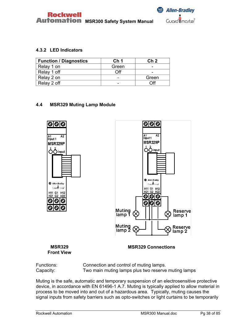
4.3.2 LED Indicators Function / Diagnostics Ch 1 Ch 2 Relay 1 on Green - Relay 1 off Off - Relay 2 on - Green Relay 2 off - Off
4.4 MSR329 Muting Lamp Module Functions: Connection and control of muting lamps. Capacity: Two main muting lamps plus two reserve muting lamps Muting is the safe, automatic and temporary suspension of an electrosensitive protective device, in accordance with EN 61496-1 A.7. Muting is typically applied to allow material in process to be moved into and out of a hazardous area. Typically, muting causes the signal inputs from safety barriers such as opto-switches or light curtains to be temporarily
MSR329 Connections MSR329 Front View

MSR300 Safety System Manual
Rockwell Automation MSR300 Manual.doc Pg 39 of 85
ignored, -A kind of muting control is implemented in an MSR300 System as part of the robot safety control function. In this special application safety cam-switches or sensors at the robot shaft initiate the muting process. These provide area position feedback to the MSR300 system in order to ignore e.g. safety light curtains as long as the robot arm is not working in the near of the light curtain protected area. Muting lamps are deployed to indicate the occurrence of muting. Special safety controls are necessary to ensure that muting lamps operate correctly and safely. The MSR329 Muting Lamp Controller is expressly designed for this purpose. An MSR329 Muting Module may be included in an MSR300 System only if at least one Input Module in the system is programmed for robot safety control. If an MSR329 is included in a system, but no Input Module has been set up for robot safety control, the Base Module will announce an invalid configuration. Two muting lamps and two spare lamps can be connected to an MSR329 Module. The valid load current range for each lamp is 30 mA to 200 mA. If the current load of a muting lamp is outside this range, the spare lamp is switched on automatically. If the defective lamp is replaced, the normal muting lamp will light up when the next muting condition occurs, and the spare lamp will remain off. If a muting lamp and its spare lamp are both defective (detected by out-of-range current), the corresponding input cannot longer be muted (which means Light curtain always monitored). Restore the muting operation requires that at least one of these two defective lamps will be replaced. If an MSR329 Muting Lamp Module fails when installed in an MSR300 System, this will result in the muting function being disabled: i.e., the corresponding light curtain will no longer be muted. The use of the MSR29 Muting Module is subject to the following system configuration rules:
• A Muting Module can be installed only in an MSR300 System that has a Robot Module (Input Module set up for robot function).
• An MSR300 System can have only one Muting Module, bus-connected instead of a normal Input Module (which leaves a maximum number of 9 Input modules to be connected when an MSR329 is used).
• An MSR300 System cannot have a Muting Module and a Logic Module (Input Module set up for logic function): i.e., the system can have either one or the other type of module, not both.
4.4.1 Terminals Name Function A1 Supply +24 VDC A2 GND, Supply 0 V H11 Muting lamp 1: positive (+) H12 Reserve lamp 1: positive (+) G1 Muting lamp 1 and reserve lamp 1: negative (-) H21 Muting lamp 2: positive (+) H22 Reserve lamp 2: positive (+) G2 Muting lamp 2 and reserve lamp 2: negative (-)

MSR300 Safety System Manual
Rockwell Automation MSR300 Manual.doc Pg 40 of 85
4.4.2 LED Indicators Function / Diagnostics H1 H2 Muting lamp 1 off Off --- Muting lamp 1 on Green --- Muting lamp 1 faulty, but reserve lamp 1 OK Red --- Muting lamp 1 and reserve lamp 1 faulty Flashes red --- Muting lamp 2 off --- Off Muting lamp --- Green Muting lamp 2 faulty, but reserve lamp 2 OK --- Red Muting lamp 2 and reserve lamp 2 faulty --- Flashes red
MSR300 Safety System Manual
Rockwell Automation MSR300 Manual.doc Pg 41 of 85
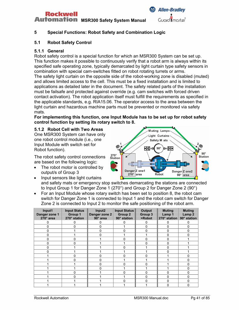
5 Special Functions: Robot Safety and Combination Logic 5.1 Robot Safety Control 5.1.1 General Robot safety control is a special function for which an MSR300 System can be set up. This function makes it possible to continuously verify that a robot arm is always within its specified safe operating zone, typically demarcated by light curtain type safety sensors in combination with special cam-switches fitted on robot rotating turrets or arms. The safety light curtain on the opposite side of the robot-working zone is disabled (muted) and allows limited access to the cell. This must be a fixed installation and is limited to applications as detailed later in the document. The safety related parts of the installation must be failsafe and protected against override (e.g. cam switches with forced driven contact activation). The robot application itself must fulfill the requirements as specified in the applicable standards, e.g. RIA15.06. The operator access to the area between the light curtain and hazardous machine parts must be prevented or monitored via safety mats. For implementing this function, one Input Module has to be set up for robot safety control function by setting its rotary switch to 8.
5.1.2 Robot Cell with Two Areas One MSR300 System can have only one robot control module (i.e., one Input Module with switch set for Robot function).
The robot safety control connections are based on the following logic: • The robot motor is controlled by
output/s of Group 3 • Input sensors like light curtains
and safety mats or emergency stop switches demarcating the stations are connected to Input Group 1 for Danger Zone 1 (270°) and Group 2 for Danger Zone 2 (90°)
• For an Input Module whose rotary switch has been set to position 8, the robot cam switch for Danger Zone 1 is connected to Input 1 and the robot cam switch for Danger Zone 2 is connected to Input 2 to monitor the safe positioning of the robot arm.
Input1 Danger zone 1
270° area
Input Status Group 1
270° station
Input2 Danger zone 2
90° area
Input Status Group 2
90° station
Output Group 3 >Robot
Muting Lamp 1
270° station
Muting Lamp 2
90° station0 0 0 0 0 0 0 0 0 0 1 0 0 0 0 1 0 0 0 0 0 0 1 0 1 1 0 0 0 0 1 0 0 0 1 0 0 1 1 0 0 1 0 1 1 0 1 0 1 0 1 1 1 1 0 1 1 0 0 0 0 1 0 1 0 0 1 1 1 0 1 1 0 0 0 1 0 1 1 0 1 1 1 0 1 0 1 0 0 0 0 1 0 1 1 0 0 0 1 1 1 0 0 0 0 1 1 1 1 1 0 0

MSR300 Safety System Manual
Rockwell Automation MSR300 Manual.doc Pg 42 of 85
Definitions: Input danger zone: 0: robot is in danger zone 1: robot is not in danger zone Input status of groups: 0: output inactive 1: output active Muting lamp: 0: lamp off 1: lamp on Implementation of an MSR300 System for robot safety control is subject to the following system configuration rules:
• One MSR300 System cannot have more than one Robot Module (Input Module set up for robot function).
• The MSR310 Input Module configured for robot safety control must have a Group 1 or Group 2 Output assigned to it. (Note: Output Module Group 1 and 2 not physically necessary )
• An MSR300 System cannot have a Robot Module (Input Module set up for robot function) and a Logic Module (Input Module set up for logic function): i.e., the system can have either one or the other type of module, not both.
5.1.3 Robot Safety Control With Additional Safe Area A robot cell can be safety-controlled for an additional safe area by a combination of two Input Modules in an MSR300 System. One Input Module is set up for robot safety control (function switch setting: 8), and a second one is set up for the additional safe area function (function switch setting: 9). One MSR300 System cannot have more than one Additional Safe Area Module: i.e., an MSR300 System can be configured for robot safety control with not more than one additional safe area. The functional logic for additional safe area control is as follows:
• The robot is controlled by the output/s of Group 3. • Inputs assigned to Group 1 monitor dangerous zone 1 (270°)(e.g. light curtains). • Inputs assigned to Group 2 monitor dangerous zone 2 (90°) (e.g. light curtains). • One input module is set up for monitoring the safe positioning of the robot arm.
(Input 1: Danger Zone 1. Input 2: Danger Zone 2). • The other input module is set up for monitoring additional safe area of the robot
cell. Implementation of an MSR300 System for robot safety control with additional safe area control is subject to the following system configuration rules:

MSR300 Safety System Manual
Rockwell Automation MSR300 Manual.doc Pg 43 of 85
• One MSR300 System cannot have more than one Additional Safe Area Module (Input Module set up for additional safe area function).
• An MSR300 System cannot have an Additional Safe Area Module (Input Module set up for additional safe are function) and a Logic Module (Input Module set up for logic function): i.e., the system can have either one or the other type of module, not both.
Input1 Danger Zone1
270°area
Input Status Group 1
270° station
Input 2 Danger Zone2
90°area
Input Status Group 2
90° station
Add Safe Area
Output Group 3
Muting Lamp 1
270°area
Muting Lamp 2 90°area
0 0 1 0 0 0 0 1 0 0 1 0 1 0 0 1 0 0 1 1 0 0 0 1 0 0 1 1 1 0 0 1 0 1 1 0 0 1 0 1 0 1 1 0 1 1 0 1 0 1 1 1 0 1 0 1 0 1 1 1 1 1 0 1 1 0 0 0 0 0 1 0 1 0 0 0 1 0 1 0 1 0 0 1 0 1 1 0 1 0 0 1 1 1 1 0 1 1 0 0 0 0 1 0 1 1 0 0 1 0 1 0 1 1 0 1 0 1 1 0 1 1 0 1 1 1 1 0 1 0 1 0 0 0 0 0 1 0 1 0 1 1 1 1 1 0 1 1 0 0 0 0 1 0 1 1 1 1 1 1 1 1 1 0 0 0 0 0 1 1 1 0 1 1 1 1 1 1 1 1 0 1 0 0 0 0 0 0 0 0 0 0 0 0 0 0 1 0 0 0 0 0 0 1 0 0 0 0 0 0 0 1 1 0 0 0 0 1 0 0 0 0 0 0 0 1 0 0 1 0 0 0 0 1 0 1 0 1 0 0 0 1 0 1 1 1 0 0
Grey marked Section at bottom: Undefined status of at least one Input, which results either in disabling the Robot operation or disabling the Muting function. As soon as Inputs are back in defined status the MSR300 automatically returns to normal operation mode. Definitions: Input danger zone: 0: robot is in danger zone 1: robot is not in danger zone Add Safe Area: 1: robot is in Add Safe Area 0: robot is not in Add Safe Area Input status of groups: 0: output inactive 1: output active Muting lamp: 0: lamp off, 1: lamp on
MSR300 Safety System Manual
Rockwell Automation MSR300 Manual.doc Pg 44 of 85
5.2 Special Logic Functions An MSR300 System can be configured for applying OR logic to a combination of inputs of one or more Input Modules. This allows e.g. limited access to dangerous areas by use of 3-position enabling switches or enabling pendants (see application examples below). Switch setting for logic function: 0 Group 3 = Input 1 OR Input 2 OR Group 1 When an MSR300 System includes more than one Input Module set for OR logic, the logic function is: Group 3 = Input 1Module1 OR Input 2Module1 OR Input 1ModuleXOR Group 1 ["X" is the input module number of the second or other Input Module] The logic function cannot be implemented in an MSR300 System that is configured for robot safety control, for additional safe area monitoring or for muting. Implementation of the logic function in an MSR300 System is subject to the following system configuration rules:
• An MSR300 System cannot have a Muting Module and a Logic Module (Input Module set up for logic function): i.e., the system can have either one or the other type of module, not both.
• An MSR300 System cannot have a Robot Module (Input Module set up for robot function) and a Logic Module (Input Module set up for logic function): i.e., the system can have either one or the other type of module, not both.
• An MSR300 System cannot have an Additional Safe Area Module (Input Module set up for additional safe are function) and a Logic Module (Input Module set up for logic function): i.e., the system can have either one or the other type of module, not both.
• A Group 3 Output Module must be included in an MSR300 System in which logic control is implemented.
• Additionally one of the Input Modules must have its output group assignment (by rotary switch) set to Group 1. This is to be done only to implement the logic function: physical connection of a group 1 output module is not necessary for this purpose, but may be used if the safety system design requires this.
MSR300 Safety System Manual
Rockwell Automation MSR300 Manual.doc Pg 45 of 85
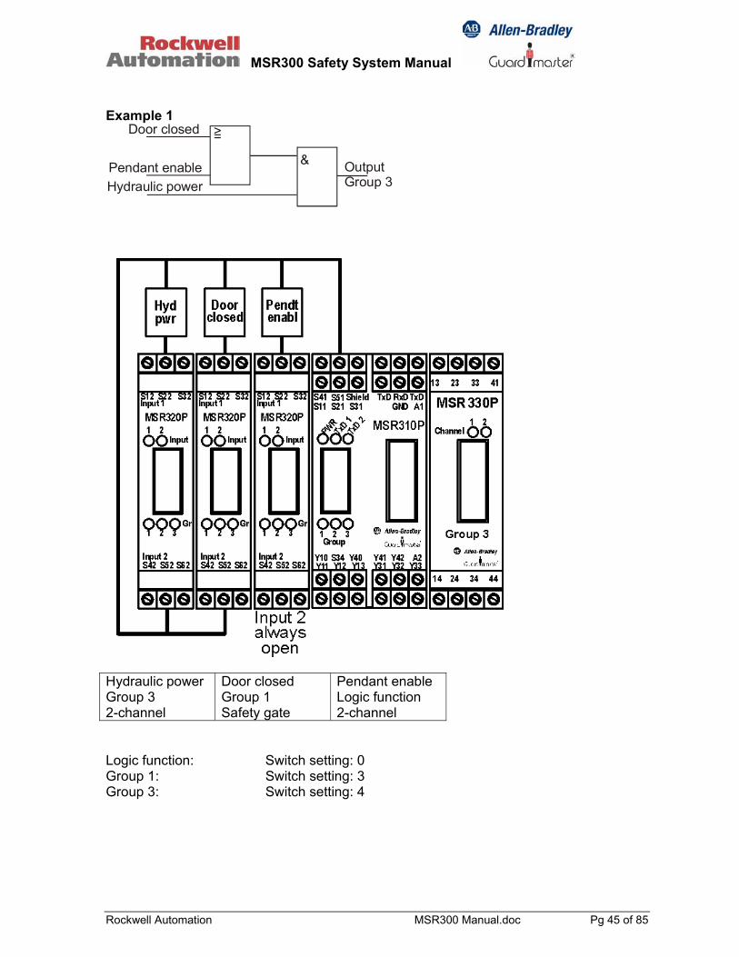
Example 1
&
>=Door closed
Pendant enableHydraulic power
OutputGroup 3
Hydraulic power Group 3 2-channel
Door closed Group 1 Safety gate
Pendant enable Logic function 2-channel
Logic function: Switch setting: 0 Group 1: Switch setting: 3 Group 3: Switch setting: 4

MSR300 Safety System Manual
Rockwell Automation MSR300 Manual.doc Pg 46 of 85
Example 2
&
&
&
>=
Door closed
Light curtain clearPendant enable
CNC E-stopOutput Group3
Output Group2
Group1
CNC E-stop Group2 + 3 2-channel
Door closed Group 1 + 2 Safety gate
Pendant enable Logic function 2-channel
Light curtain Group 1 2-channel

MSR300 Safety System Manual
Rockwell Automation MSR300 Manual.doc Pg 47 of 85
Example 3
&
&
&
>=
Door closed
Light curtain clearPendant enable 2
CNC E-stopOutputGroup 3
OutputGroup 2
Pendant enable 1
CNC E-stop Group2 + 3 2-channel
Door closed Group 1 + 2 Safety gate
Pendant enable Logic function 2-channel
Light curtain Group 1 2-channel

MSR300 Safety System Manual
Rockwell Automation MSR300 Manual.doc Pg 48 of 85
Example 4 (Zoning application without OR-logic function)
&
Door closedLight curtain
clear
Front gateCNC E-stop Output
Group 1
OutputGroup 2
&
CNC E-stop Group 1 + 2 2-channel
Door closed Group 1 + 2 Safety gate
Front gate Group 1 Safety gate
Light curtain Group 1 2-channel
MSR300 Safety System Manual
Rockwell Automation MSR300 Manual.doc Pg 49 of 85
6 Faults Detection and Response [Note: In the following part of this document, "fault" can mean the occurrence of an internal failure or defect, an external wiring or signal error, or a system configuration error]. The MSR300 System has extensive error detection capabilities. Faults, symptoms and corrective action are categorized and described below. 6.1 Major Faults Major faults are indicated by the "Status" LED lighting up red continuously. These faults include:
• The two redundant microprocessors of the MSR310 Base Module perceive different operating states of the system as a whole.
• Tripping due to: • Difference in the settings of the two redundant sets of rotary switches of any
Input Module • Detection of high level of electromagnetic radiation • Internal fault/s
MSR300 Safety System Manual
Rockwell Automation MSR300 Manual.doc Pg 50 of 85
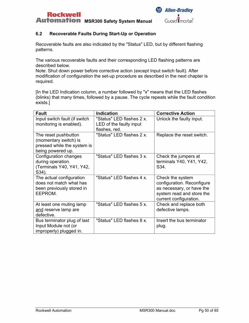
6.2 Recoverable Faults During Start-Up or Operation Recoverable faults are also indicated by the "Status" LED, but by different flashing patterns. The various recoverable faults and their corresponding LED flashing patterns are described below. Note: Shut down power before corrective action (except Input switch fault). After modification of configuration the set-up procedure as described in the next chapter is required. [In the LED Indication column, a number followed by "x" means that the LED flashes (blinks) that many times, followed by a pause. The cycle repeats while the fault condition exists.] Fault Indication Corrective Action Input switch fault (if switch monitoring is enabled).
"Status" LED flashes 2 x. LED of the faulty input flashes, red.
Unlock the faulty input.
The reset pushbutton (momentary switch) is pressed while the system is being powered up.
"Status" LED flashes 2 x. Replace the reset switch.
Configuration changes during operation. (Terminals Y40, Y41, Y42, S34).
"Status" LED flashes 3 x. Check the jumpers at terminals Y40, Y41, Y42, S34.
The actual configuration does not match what has been previously stored in EEPROM.
"Status" LED flashes 4 x. Check the system configuration. Reconfigure as necessary, or have the system read and store the current configuration.
At least one muting lamp and reserve lamp are defective.
"Status" LED flashes 5 x. Check and replace both defective lamps.
Bus terminator plug of last Input Module not (or improperly) plugged in.
"Status" LED flashes 8 x. Insert the bus terminator plug.
MSR300 Safety System Manual
Rockwell Automation MSR300 Manual.doc Pg 51 of 85
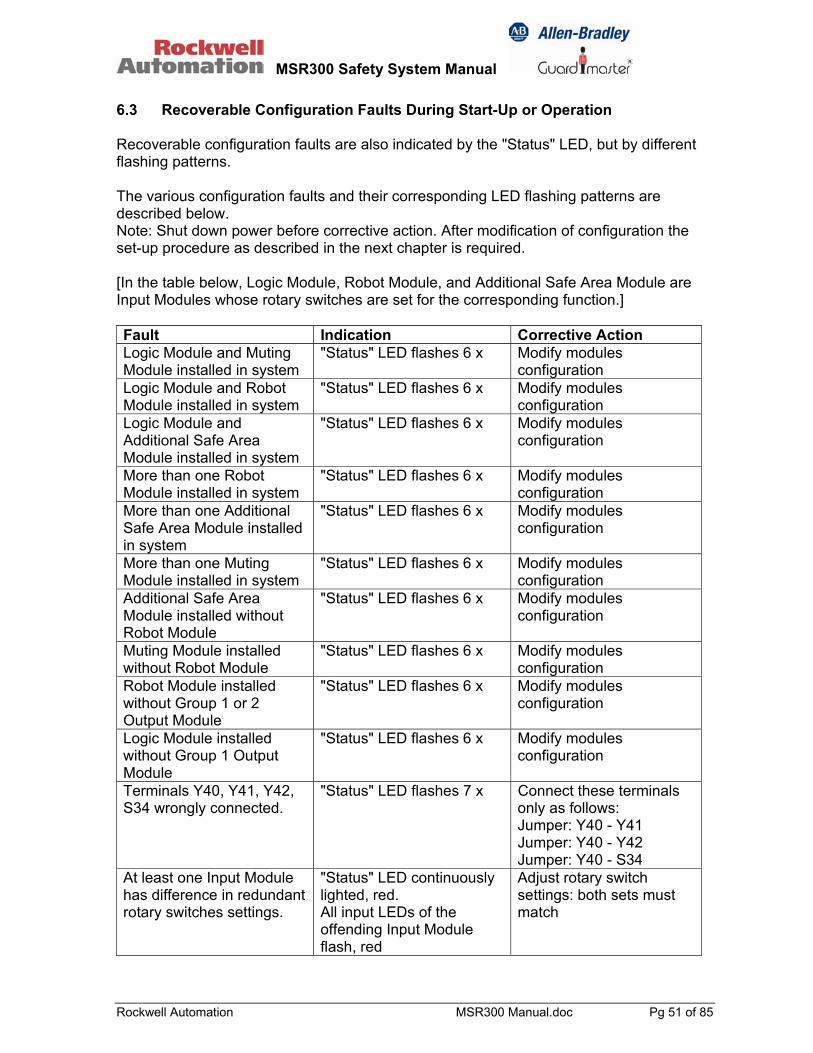
6.3 Recoverable Configuration Faults During Start-Up or Operation Recoverable configuration faults are also indicated by the "Status" LED, but by different flashing patterns. The various configuration faults and their corresponding LED flashing patterns are described below. Note: Shut down power before corrective action. After modification of configuration the set-up procedure as described in the next chapter is required. [In the table below, Logic Module, Robot Module, and Additional Safe Area Module are Input Modules whose rotary switches are set for the corresponding function.] Fault Indication Corrective Action Logic Module and Muting Module installed in system
"Status" LED flashes 6 x Modify modules configuration
Logic Module and Robot Module installed in system
"Status" LED flashes 6 x Modify modules configuration
Logic Module and Additional Safe Area Module installed in system
"Status" LED flashes 6 x Modify modules configuration
More than one Robot Module installed in system
"Status" LED flashes 6 x Modify modules configuration
More than one Additional Safe Area Module installed in system
"Status" LED flashes 6 x Modify modules configuration
More than one Muting Module installed in system
"Status" LED flashes 6 x Modify modules configuration
Additional Safe Area Module installed without Robot Module
"Status" LED flashes 6 x Modify modules configuration
Muting Module installed without Robot Module
"Status" LED flashes 6 x Modify modules configuration
Robot Module installed without Group 1 or 2 Output Module
"Status" LED flashes 6 x Modify modules configuration
Logic Module installed without Group 1 Output Module
"Status" LED flashes 6 x Modify modules configuration
Terminals Y40, Y41, Y42, S34 wrongly connected.
"Status" LED flashes 7 x Connect these terminals only as follows: Jumper: Y40 - Y41 Jumper: Y40 - Y42 Jumper: Y40 - S34
At least one Input Module has difference in redundant rotary switches settings.
"Status" LED continuously lighted, red. All input LEDs of the offending Input Module flash, red
Adjust rotary switch settings: both sets must match

MSR300 Safety System Manual
Rockwell Automation MSR300 Manual.doc Pg 52 of 85
7 Installation, Start-Up, Operation, Maintenance 7.1 Safety Precautions and Practices
Use this product only for intended applications: The MSR300 Safety System is intended for applications requiring safety monitoring of machinery in accordance with the following directives / standards: • EN954-1: Safety-Related Parts Of Control Systems. • IEC 61508: Functional Safety of Electrical / Electronic /
Programmable Electronic Safety-Related Systems, Parts 1-7, 1998.
This equipment must not be used for unintended applications, nor in ways that do not conform to appropriate safety standards and good practices. The safety functions may not operate properly (or at all) if this equipment is not used for the intended purposes. Installation and operation to be done only by qualified technical personnel: This equipment is to be installed, started up, and operated only by technical personnel who have been trained and made familiar with: • The product/s for which this document exists • Directives, regulations and practices relating to machine safety • Instrumentation and automation components, equipment and
systems • Industrial electrical practices Uptodate user documentation must readily accessible by technical personnel: The latest version of user documentation that includes instructions for installation, operation and maintenance of this product must be readily available near at hand to personnel involved in any of these tasks. Identify hazardous areas and dangerous operating modes before using: Machine safety applications make it necessary for hazardous areas and dangerous operating modes to be carefully identified, and adequate measures taken to ensure that failure or tampering does not allow automated equipment to be of risk to personnel. Use within specified operating limits: This product, the equipment on which it installed, persons handling the product and equipment, and/or the immediate environment can be harmed if this equipment is operated outside the specified limits of any of its technical parameters.

MSR300 Safety System Manual
Rockwell Automation MSR300 Manual.doc Pg 53 of 85
Observe electrical safety regulations and good practices: Electrical safety regulations stipulated by the appropriate technical authorities must be observed. Do not use if the product is damaged or diminished in any way: Carefully inspect each module before it is installed (or re-installed). If at any time it is observed that the condition of equipment is diminished in any way so that there is even the slightest possibility of incorrect functioning, it should be assumed that safe operation is no longer possible, and the equipment should be removed immediately so that even unintentional operation is made impossible. Examples of such conditions are: • Visible damage to the equipment • Loss of electrical function/s • Exposure to temperatures higher the specified operating limit • Visible indication of burning • Visible physical damage due to impact or excessive mechanical
shock Do not attempt to open the housing or repair any of the modules: It is forbidden for safety control products such as this to be repaired or modified in any way: this can diminish or render inoperative its critical safety functions. A malfunctioning or damaged module must be immediately removed, so that even inadvertent operation of the system becomes impossible in such circumstances. An identical module should be installed in its place, after the new module has been tested to confirm that it is in proper working condition. Opening the enclosure of a module will immediately void its warranty.

MSR300 Safety System Manual
Rockwell Automation MSR300 Manual.doc Pg 54 of 85
7.2 Installation 7.2.1 Environmental Considerations
MSR300 Series Modules must be installed inside protected control panels / cabinets appropriate for the environmental conditions of the industrial location. The protection class of the panel / cabinet should preferably be IP 54 or higher. The environmental protection ratings of the modules in accordance with IEC/EN 60529 are: Housing: IP 40 Terminals: IP 20 Operating ambient condition limits are: Operating temperature: -5°C to +55°C (+23°F to 131°F) Relative humidity (RH): 90% (max.)

MSR300 Safety System Manual
Rockwell Automation MSR300 Manual.doc Pg 55 of 85
7.2.2 Mechanical Dimensions: Side view and dimensions: all MSR300 Modules
Spacing: Adequate air space must be provided around the system (modules cluster). Minimum recommended clearances: Above: 15 mm Below: 15 mm Between modules: 2 - 3 mm recommended at ambient temperatures higher than +40°C
/ +104°F Mounting and removal: The modules are mounted on standard DIN 35 mm rails.
To mount the module, first engage its bottom lips with the upper flange of the DIN rail, then rotate and press the module down until the latch snaps onto the lower flange of the DIN rail. To dismount the module, first disengage the latch from the lower flange of the DIN rail, turn the module upward slightly, then lift the module up to disengage its bottom lips from the upper flange of the DIN rail.
Modules widths: MSR310 = 35 mm / 1.78 in. MSR320 = 17.5 mm / 0.69 in. MSR329 = 17.5 mm / 0.69 in. MSR330 = 22.5 mm / 0.89 in.

MSR300 Safety System Manual
Rockwell Automation MSR300 Manual.doc Pg 56 of 85
Vibration and mechanical shock: The MSR300 modules must not be subjected to vibration or mechanical in excess of the specified limits (in accordance with IEC 68 part: 2-6/7): Vibration: 10 – 55 Hz, 0.35 mm Mechanical shock: 10g, 16 msec, 100 shocks 7.2.3 Electrical For planning information, refer to the guidelines in the document "Industrial Automation Wiring and Grounding Guidelines" (Allen Bradley Publication 1770-4.1). Removing the terminal blocks:
Make sure that electrical power supply to MSR300 System is switched off before making or removing any electrical connections, Connecting wires should be installed so that no mechanical forces (e.g., mechanical tension) are transmitted through them to the modules, particularly the terminals. Tighten all terminal screws firmly (*) and re-check all after connections have been made. (* Recommended screw-tightening torque: 0.6 to 0.8 Nm or 5 to 7 lb-in). Suitable arc and spike suppression components must be connected across load devices of switching outputs (electromechanical contacts or solid-state switch) where the load devices are inductive or capacitive.
• To remove the terminal block, insert the screw driver in position 1and then move it slowly to position 2. For the lower terminal blocks, the action will be in the reverse direction
The external power supply unit for the MSR300 System must conform to the Directive 73/23/EEC Low Voltage, by applying the requirements of EN 61131-2 Programmable Controllers, Part 2 - Equipment Requirements and Tests, and one of the following: • EN 60950 - SELV (Safety Extra Low Voltage) • EN 60204 - PELV (Protective Extra Low Voltage) • IEC 60536 Safety Class III (SELV or PELV)

MSR300 Safety System Manual
Rockwell Automation MSR300 Manual.doc Pg 57 of 85
7.3 Set-Up After the MSR300 System has been assembled, it must be programmed with information about the system modules configuration. This data is stored in non-volatile memory and compared with the configuration detected each time the system is switched on. Any difference between the freshly detected configuration and the programmed configuration is interpreted as an error condition. This prevents unintentional modifications in the system configuration. Configuration detection and saving: Unintended modifications to MSR300 Systems are prevented by design. The system configuration is automatically checked when it is first started up, and this information is stored in non-volatile memory (EEPROM) in the Base Module. Whenever the system is started up (or restarted) thereafter, the current system configuration is checked against the stored configuration. If a discrepancy is detected, a fault response is immediately generated, with appropriate diagnostic indication and output. The Base Module is set up in auto-detection mode as default. If it is powered up the first time it will automatically read in the configuration of the connected modules. Follow the procedure below for changes or modifications of the configuration.
Procedure for auto detecting and storing a new system configuration: 1. Disconnect Expansion Modules from the Base Module. 2. Insert the bus terminator plug into the left bus connector. 3. Power up the Base Module: a) The "Status" LED blinks to indicate that the Base Module is in configuration detection mode. LED indication:
b) The previous configuration is erased. 4. Disconnect the power after at least one blink of the LED. 5. Remove the bus terminator plug from the Base Module, and
then connect the required Expansion Modules to the Base Module.
6. Insert the bus terminator plug into the free bus connector of the last Expansion Module.
7. Power up the system. After powering up, the current configuration is detected and stored by the Base Module in internal EEPROM.
8. The MSR300 System then automatically steps into normal operating mode.

MSR300 Safety System Manual
Rockwell Automation MSR300 Manual.doc Pg 58 of 85
7.4 Operation Once an MSR300 System is correctly set up, it starts and operates automatically in accordance with the settings done: it needs no operator attention or action during its normal operation 7.5 Maintenance An MSR300 System that is correctly configured, set up and installed is inherently maintenance-free.
Do not attempt to open the housing or repair any of the modules: • It is forbidden for safety control products such as this to be
repaired or modified in any way: this can diminish or render inoperative its critical safety functions.
• Opening the enclosure of a module will immediately void its warranty.
Defective or damaged modules must be immediately
removed to prevent unintentional usage, and replaced before attempting to operate the machinery under the control of this safety system.
It is recommended that the integrity of all electrical connections (tightness of terminal screws, firm seating of the plug-in terminal blocks) be inspected at planned intervals.
System checking: Input devices (safety sensors) and output devices (e.g. contactors) should be inspected and tested at planned intervals to confirm they are in good operating condition. The complete safety system should be inspected and tested at planned intervals, to confirm that all safety functions are operating correctly, e.g., by activating the safety sensors under safe conditions. Inspection and test schedules depend on operating and site conditions, and on the user's operations and maintenance policies. Test intervals for SIL3 applications depend on system and input configuration: e.g. worst case scenario: full configuration with 20 single channel inputs and 6 output modules should be tested at approx. 4.38 month
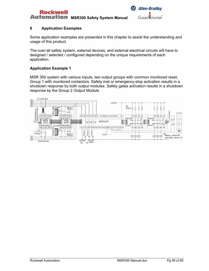
MSR300 Safety System Manual
Rockwell Automation MSR300 Manual.doc Pg 59 of 85
8 Application Examples Some application examples are presented in this chapter to assist the understanding and usage of this product. The over-all safety system, external devices, and external electrical circuits will have to designed / selected / configured depending on the unique requirements of each application. Application Example 1 MSR 300 system with various Inputs, two output groups with common monitored reset, Group 1 with monitored contactors. Safety mat or emergency-stop activation results in a shutdown response by both output modules. Safety gates activation results in a shutdown response by the Group 2 Output Module.
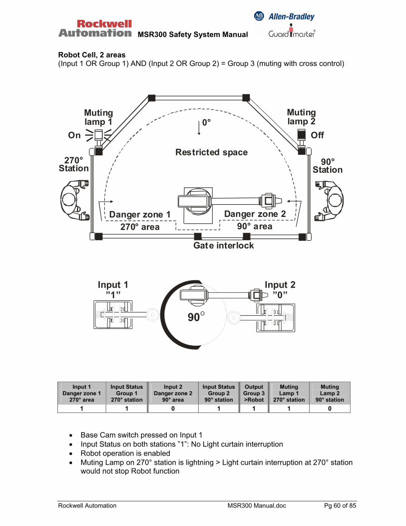
MSR300 Safety System Manual
Rockwell Automation MSR300 Manual.doc Pg 60 of 85
Robot Cell, 2 areas (Input 1 OR Group 1) AND (Input 2 OR Group 2) = Group 3 (muting with cross control)
Mutinglamp 1
Mutinglamp 2
On Off
Restricted space
Gate interlock
0°
Danger zone 1270° area
270°Station
Danger zone 290° area
90°Station
90O
Input 1”1”
Input 2”0”
Input 1 Danger zone 1
270° area
Input Status Group 1
270° station
Input 2 Danger zone 2
90° area
Input Status Group 2
90° station
Output Group 3>Robot
Muting Lamp 1
270° station
Muting Lamp 2
90° station 1 1 0 1 1 1 0
• Base Cam switch pressed on Input 1 • Input Status on both stations ”1”: No Light curtain interruption • Robot operation is enabled • Muting Lamp on 270° station is lightning > Light curtain interruption at 270° station
would not stop Robot function
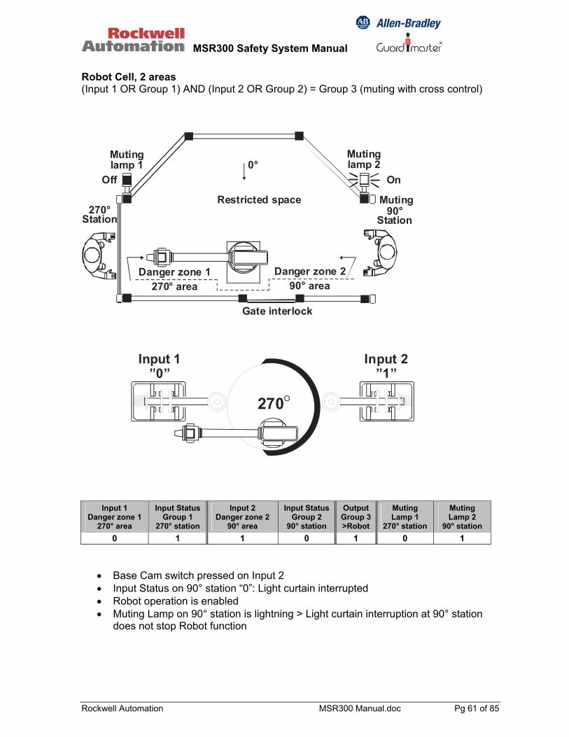
MSR300 Safety System Manual
Rockwell Automation MSR300 Manual.doc Pg 61 of 85
Robot Cell, 2 areas (Input 1 OR Group 1) AND (Input 2 OR Group 2) = Group 3 (muting with cross control)
Mutinglamp 1
Mutinglamp 2
OnOff0°
270°Station
Danger zone 290° area
90°Station
Restricted space
Gate interlock
Muting
Danger zone 1270° area
Input 1”0”
Input 2”1”
270O
Input 1 Danger zone 1
270° area
Input Status Group 1
270° station
Input 2 Danger zone 2
90° area
Input Status Group 2
90° station
Output Group 3>Robot
Muting Lamp 1
270° station
Muting Lamp 2
90° station 0 1 1 0 1 0 1
• Base Cam switch pressed on Input 2 • Input Status on 90° station “0”: Light curtain interrupted • Robot operation is enabled • Muting Lamp on 90° station is lightning > Light curtain interruption at 90° station
does not stop Robot function

MSR300 Safety System Manual
Rockwell Automation MSR300 Manual.doc Pg 62 of 85
Robot Cell, 2 areas (Input 1 OR Group 1) AND (Input 2 OR Group 2) = Group 3 (muting with cross control)
Mutinglamp 1
Mutinglamp 2
On Off
Restricted space
0°
Danger zone 1270° area
270°Station
Danger zone 290° area
Muting90°
Station
90O
Input 1”1”
Input 2”0”
Input 1 Danger zone 1
270° area
Input Status Group 1
270° station
Input 2 Danger zone 2
90° area
Input Status Group 2
90° station
Output Group 3>Robot
Muting Lamp 1
270° station
Muting Lamp 2
90° station 1 0 0 1 1 1 0
• Base Cam switch pressed on Input 1 • Input Status on 270° station “0”: Light curtain interrupted • Robot operation is enabled • Muting Lamp on 270° station is lightning > Light curtain interruption at 270° station
does not stop Robot function

MSR300 Safety System Manual
Rockwell Automation MSR300 Manual.doc Pg 63 of 85
Robot Cell, 2 areas (Input 1 OR Group 1) AND (Input 2 OR Group 2) = Group 3 (muting with cross control)
OnOff
Restricted spaceNo muting
0°
Danger zone 1270° area
270°Station
Danger zone 290° area
90°Station
Mutinglamp 1
Mutinglamp 2
Input 1”0”
Input 2”1”
270O
Input 1 Danger zone 1
270° area
Input Status Group 1
270° station
Input 2 Danger zone 2
90° area
Input Status Group 2
90° station
Output Group 3>Robot
Muting Lamp 1
270° station
Muting Lamp 2
90° station 0 0 1 1 0 0 1
• Base Cam switch pressed on Input 2 • Input Status on 270° station “0”: Light curtain interrupted • Robot operation disabled (stopped) because operator enters danger zone 1 while
Robot arm is present • No Muting Lamp indication for 270° station • Muting Lamp on 90° station is lightning > Light curtain interruption at 90° station
would not stop Robot function
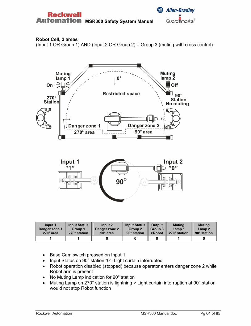
MSR300 Safety System Manual
Rockwell Automation MSR300 Manual.doc Pg 64 of 85
Robot Cell, 2 areas (Input 1 OR Group 1) AND (Input 2 OR Group 2) = Group 3 (muting with cross control)
On Off
Restricted space
No muting
0°
Danger zone 1270° area
270°Station
Danger zone 290° area
90°Station
Mutinglamp 1
Mutinglamp 2
90O
Input 1”1”
Input 2”0”
Input 1 Danger zone 1
270° area
Input Status Group 1
270° station
Input 2 Danger zone 2
90° area
Input Status Group 2
90° station
Output Group 3>Robot
Muting Lamp 1
270° station
Muting Lamp 2
90° station 1 1 0 0 0 1 0
• Base Cam switch pressed on Input 1 • Input Status on 90° station “0”: Light curtain interrupted • Robot operation disabled (stopped) because operator enters danger zone 2 while
Robot arm is present • No Muting Lamp indication for 90° station • Muting Lamp on 270° station is lightning > Light curtain interruption at 90° station
would not stop Robot function

MSR300 Safety System Manual
Rockwell Automation MSR300 Manual.doc Pg 65 of 85
Robot cell, 2 areas Modules and I/O configuration
MSR300 System configuration: MSR310 Base Module – 1 MSR320 Input Modules – 3 MSR330 Output Module – 1 MSR329 Muting Lamp Module – 1 I/O: A, I = Light curtain inputs C, H = Safety mat inputs D, F = Robot cam switch inputs B, G = Muting lamp control E = Robot run/stop output
90O
Input 1”1”
Input 1”0”
Input 1”1”
Input 2”0”
Input 2”1”
Input 2”1”
270O
0O
Base Cam Switches in various Robot Arm Positions

MSR300 Safety System Manual
Rockwell Automation MSR300 Manual.doc Pg 66 of 85
Robot Cell 3 Areas
Restrictedspace
Restrictedspace
Mutinglamp
Mutinglamp
OnOff
Light curtain muted
Light curtain active
Additionalsafe area
On if insafe area( )
Pos 1
Pos 2 0°
Danger zone 1270° area
270°Station
Danger zone 290° area
90°Station
Input1 Danger Zone 1
270°area
Input Status Group 1
270° station
Input 2 Danger Zone 2 90°area
Input Status Group 2
90° station
Add Safe Area
Output Group 3 >Robot
Muting Lamp1
270° station
Muting Lamp2
90° station
Pos 1 1 0 0 1 0 1 1 0 Pos 2 1 0 1 1 1 1 1 1
Input 1 270°area = Light curtain (and Safety Mat) at 270 Station Status Group 1 = Robot arm in 270° area (Cam limit switches) Inpur 2 90° area = Light curtain (and Safety Mat) at 90° Station Status Group 2 = Robot arm in 90° area (Cam limit switches) Add. = Robot arm in safe distance from Safe Area both: 270° area and 90° area Output = Robot operation > 1: enable, 0: disable

MSR300 Safety System Manual
Rockwell Automation MSR300 Manual.doc Pg 67 of 85
Robot cell 3 areas Modules and I/O configuration
Restrictedspace Restricted
space
Mutinglamp
Mutinglamp
On
270° 90°
Operator Load Station 1
Light curtain muted
Operator Load Station 2Light curtain active
A2Y10Y13
S34 Y42Y31 Y32 Y33
Y40 Y41
Group1 2 3
MSR310PPWR
TxD 2
S11 S21 S31S41 S51
A1TxDShield RxDTxD
GNDS12 S22 S32
S42 S52 S62
1 2 3
MSR320P
Input1 2
Input 1
Input 2
Gr
13 23
14 24
MSR330P1 2
4133
34 44
Group 3
Channel
S12 S22 S32
S42 S52 S62
1 2 3
MSR320P
Input1 2
Input 1
Input 2
Gr
S12 S22 S32
S42 S52 S62
1 2 3
MSR320P
Input1 2
Input 1
Input 2
Gr
A1 A2
H21H11
H22H12
MSR329PInput
1 2
Input 1S12 S22 S32
S42 S52 S62
1 2 3
MSR320P
Input1 2
Input 1
Input 2
Gr
Additionalsafe area
0 degrees
AB C E
J
F G
HID
MSR300 System configuration: MSR310 Base Module – 1 MSR320 Input Modules – 4 MSR330 Output Module – 1 MSR329 Muting Lamp Module – 1 I/O: A, I = Light curtain inputs C, H = Safety mat inputs D, F = Robot cam switch inputs B, G = Muting lamp control E = Robot run/stop output J = “Addl. Safe Area” cam switch
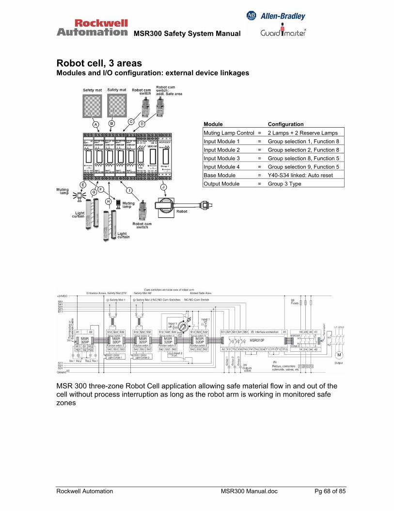
MSR300 Safety System Manual
Rockwell Automation MSR300 Manual.doc Pg 68 of 85
Robot cell, 3 areas Modules and I/O configuration: external device linkages
Module Configuration Muting Lamp Control = 2 Lamps + 2 Reserve Lamps Input Module 1 = Group selection 1, Function 8 Input Module 2 = Group selection 2, Function 8 Input Module 3 = Group selection 8, Function 5 Input Module 4 = Group selection 9, Function 5 Base Module = Y40-S34 linked: Auto reset Output Module = Group 3 Type
MSR 300 three-zone Robot Cell application allowing safe material flow in and out of the cell without process interruption as long as the robot arm is working in monitored safe zones

MSR300 Safety System Manual
Rockwell Automation MSR300 Manual.doc Pg 69 of 85
9 Serial Data Communication: Details The MSR310 is equipped with two RS232 serial data interfaces: one can be used in bi-directional, the other in uni-directional mode. 9.1 Serial Data Interface Connections The serial interface connections are illustrated below.
TxD1RxD1GND
RS-232Bi-
directional
TxD2
GND
RS-232Uni-directional
9.2 RS232 Bi-directional Bi-directional RS232 features automatic baud rate detection, and can handle baud rates of 2400, 4800, 9600, or 19200 baud. 9.2.1 Protocol: Supported exception codes: Code Name Meaning 0x01 Illegal function The function code is not supported by the
MSR310 0x02 Illegal data address The data address in the query is not allowed
for the MSR310 0x03 Illegal Data Value The data value in the query is not valid Supported functions: Code Name Meaning 0x03 Read Multiple
Registers Reads the contents of a sequence of registers
0x06 Write Single Register
Writes a value to a single register.
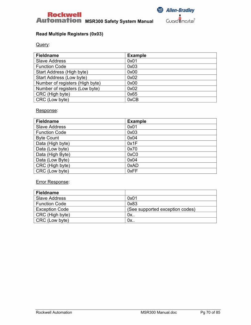
MSR300 Safety System Manual
Rockwell Automation MSR300 Manual.doc Pg 70 of 85
Read Multiple Registers (0x03) Query: Fieldname Example Slave Address 0x01 Function Code 0x03 Start Address (High byte) 0x00 Start Address (Low byte) 0x02 Number of registers (High byte) 0x00 Number of registers (Low byte) 0x02 CRC (High byte) 0x65 CRC (Low byte) 0xCB Response: Fieldname Example Slave Address 0x01 Function Code 0x03 Byte Count 0x04 Data (High byte) 0x1F Data (Low byte) 0x70 Data (High Byte) 0xC0 Data (Low Byte) 0x04 CRC (High byte) 0xAD CRC (Low byte) 0xFF Error Response: Fieldname Slave Address 0x01 Function Code 0x83 Exception Code (See supported exception codes) CRC (High byte) 0x.. CRC (Low byte) 0x..
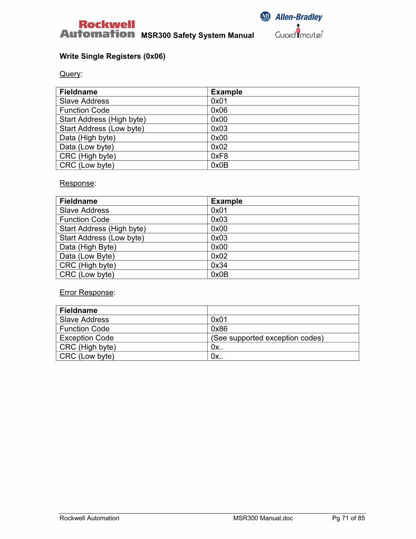
MSR300 Safety System Manual
Rockwell Automation MSR300 Manual.doc Pg 71 of 85
Write Single Registers (0x06) Query: Fieldname Example Slave Address 0x01 Function Code 0x06 Start Address (High byte) 0x00 Start Address (Low byte) 0x03 Data (High byte) 0x00 Data (Low byte) 0x02 CRC (High byte) 0xF8 CRC (Low byte) 0x0B Response: Fieldname Example Slave Address 0x01 Function Code 0x03 Start Address (High byte) 0x00 Start Address (Low byte) 0x03 Data (High Byte) 0x00 Data (Low Byte) 0x02 CRC (High byte) 0x34 CRC (Low byte) 0x0B Error Response: Fieldname Slave Address 0x01 Function Code 0x86 Exception Code (See supported exception codes) CRC (High byte) 0x.. CRC (Low byte) 0x..

MSR300 Safety System Manual
Rockwell Automation MSR300 Manual.doc Pg 72 of 85
9.2.2 MSR310 Parameters Para-meter
R/W Name Size Value Address
1 R Device status 2 bytes 0x0000 – 0xFFFF 0x0000 2 R Input status 1 2 bytes 0x0000 – 0xFFFF 0x0001 3 R Input status 2 2 bytes 0x0000 – 0xFFFF 0x0002 4 R Configuration status EM 1 2 bytes 0x0000 – 0xFFFF 0x0003 5 R Configuration status EM 2 2 bytes 0x0000 – 0xFFFF 0x0004 6 R Configuration status EM 3 2 bytes 0x0000 – 0xFFFF 0x0005 7 R Configuration status EM 4 2 bytes 0x0000 – 0xFFFF 0x0006 8 R Configuration status EM 5 2 bytes 0x0000 – 0xFFFF 0x0007 9 R Configuration status EM 6 2 bytes 0x0000 – 0xFFFF 0x0008 10 R Configuration status EM 7 2 bytes 0x0000 – 0xFFFF 0x0009 11 R Configuration status EM 8 2 bytes 0x0000 – 0xFFFF 0x000A 12 R Configuration status EM 9 2 bytes 0x0000 – 0xFFFF 0x000B 13 R Configuration status EM 10 2 bytes 0x0000 – 0xFFFF 0x000C 14 R Input with error monitoring:
extension modules 1 to 8 2 bytes 0x0000 – 0xFFFF 0x000D
15 R Input with error monitoring: extension modules 9 to 10
2 bytes 0x0000 – 0xFFFF 0x000E
16 R Input switch error status 2 bytes 0x0000 – 0xFFFF 0x000F 17 R Input switch error status, other
faults, version number, number of input modules
2 bytes 0x0000 – 0xFFFF 0x0010
18 R/W Bus status (Baud rate) 2 bytes 0x0000 – 0x0300 0x0011 Status of device (Parameter 1: configuration and status of device) High Byte: Bit Function 7 + 6 00: Jumper Y40 – Y41–Y42
01: Jumper Y40 – Y41 10: Jumper Y40 – Y42 11: Y41 and Y42 open
5 Group 3 active 4 Group 2 active 3 Group 1 active 2 Group 3 ready 1 Group 2 ready 0 Group 1 ready
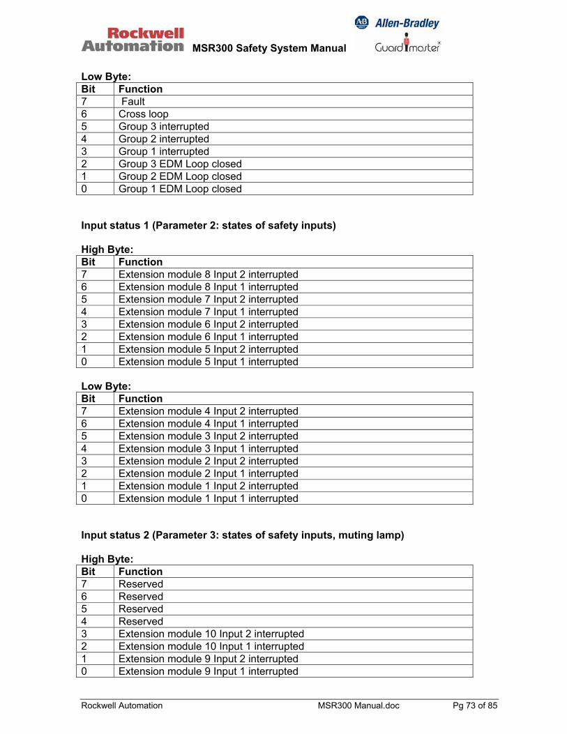
MSR300 Safety System Manual
Rockwell Automation MSR300 Manual.doc Pg 73 of 85
Low Byte: Bit Function 7 Fault 6 Cross loop 5 Group 3 interrupted 4 Group 2 interrupted 3 Group 1 interrupted 2 Group 3 EDM Loop closed 1 Group 2 EDM Loop closed 0 Group 1 EDM Loop closed Input status 1 (Parameter 2: states of safety inputs) High Byte: Bit Function 7 Extension module 8 Input 2 interrupted 6 Extension module 8 Input 1 interrupted 5 Extension module 7 Input 2 interrupted 4 Extension module 7 Input 1 interrupted 3 Extension module 6 Input 2 interrupted 2 Extension module 6 Input 1 interrupted 1 Extension module 5 Input 2 interrupted 0 Extension module 5 Input 1 interrupted Low Byte: Bit Function 7 Extension module 4 Input 2 interrupted 6 Extension module 4 Input 1 interrupted 5 Extension module 3 Input 2 interrupted 4 Extension module 3 Input 1 interrupted 3 Extension module 2 Input 2 interrupted 2 Extension module 2 Input 1 interrupted 1 Extension module 1 Input 2 interrupted 0 Extension module 1 Input 1 interrupted Input status 2 (Parameter 3: states of safety inputs, muting lamp) High Byte: Bit Function 7 Reserved 6 Reserved 5 Reserved 4 Reserved 3 Extension module 10 Input 2 interrupted 2 Extension module 10 Input 1 interrupted 1 Extension module 9 Input 2 interrupted 0 Extension module 9 Input 1 interrupted

MSR300 Safety System Manual
Rockwell Automation MSR300 Manual.doc Pg 74 of 85
Low Byte: Bit Function 7 Reserved 6 Fault: Different switch settings of input modules between the two channels 5 Fault: Invalid configuration of extension modules 4 Fault: Reserve Muting lamp 2 3 Fault: Muting lamp 2 2 Fault: Reserve Muting lamp 1 1 Fault: Muting lamp 1 0 Fault: at least one Input (lock-out-release, no synchrony activity) Configuration status (Parameters 4 ... 13: current configuration of Extension modules 1...10) High Byte: Bit Function 7 Switch settings of function bit 3 6 Switch settings of function bit 2 5 Switch settings of function bit 1 4 Switch settings of function bit 0 3 Switch settings of group bit 3 2 Switch settings of group bit 2 1 Switch settings of group bit 1 0 Switch settings of group bit 0 Low Byte: Bit Function 7 Stored EEPROM settings of function bit 3 6 Stored EEPROM settings of function bit 2 5 Stored EEPROM settings of function bit 1 4 Stored EEPROM settings of function bit 0 3 Stored EEPROM settings of group bit 3 2 Stored EEPROM settings of group bit 2 1 Stored EEPROM settings of group bit 1 0 Stored EEPROM settings of group bit 0 Configuration status (Parameter 14: input with error monitoring) High Byte: Bit Function 7 Input error monitoring, extension module 8, input 2 6 Input error monitoring, extension module 8, input 1 5 Input error monitoring, extension module 7, input 2 4 Input error monitoring, extension module 7, input 1 3 Input error monitoring, extension module 6, input 2 2 Input error monitoring, extension module 6, input 1 1 Input error monitoring, extension module 5, input 2 0 Input error monitoring, extension module 5, input 1

MSR300 Safety System Manual
Rockwell Automation MSR300 Manual.doc Pg 75 of 85
Low Byte: Bit Function 7 Input error monitoring, extension module 4, input 2 6 Input error monitoring, extension module 4, input 1 5 Input error monitoring, extension module 3, input 2 4 Input error monitoring, extension module 3, input 1 3 Input error monitoring, extension module 2, input 2 2 Input error monitoring, extension module 2, input 1 1 Input error monitoring, extension module 1, input 2 0 Input error monitoring, extension module 1, input 1 Configuration status (Parameter 15: input with error monitoring) High Byte: Bit Function 7 Reserved 6 Reserved 5 Reserved 4 Reserved 3 Reserved 2 Reserved 1 Reserved 0 Reserved Low Byte: Bit Function 7 Reserved 6 Reserved 5 Reserved 4 Reserved 3 Input error monitoring, extension module 10, input 2 2 Input error monitoring, extension module 10, input 1 1 Input error monitoring, extension module 9, input 2 0 Input error monitoring, extension module 9, input 1 Error status 1 (Parameter 16: input switch faults) High Byte: Bit Function 7 Faulty input switch, extension module 8, input 2 6 Faulty input switch, extension module 8, input 1 5 Faulty input switch, extension module 7, input 2 4 Faulty input switch, extension module 7, input 1 3 Faulty input switch, extension module 6, input 2 2 Faulty input switch, extension module 6, input 1 1 Faulty input switch, extension module 5, input 2 0 Faulty input switch, extension module 5, input 1
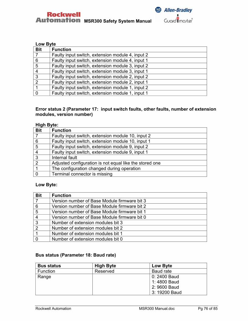
MSR300 Safety System Manual
Rockwell Automation MSR300 Manual.doc Pg 76 of 85
Low Byte Bit Function 7 Faulty input switch, extension module 4, input 2 6 Faulty input switch, extension module 4, input 1 5 Faulty input switch, extension module 3, input 2 4 Faulty input switch, extension module 3, input 1 3 Faulty input switch, extension module 2, input 2 2 Faulty input switch, extension module 2, input 1 1 Faulty input switch, extension module 1, input 2 0 Faulty input switch, extension module 1, input 1 Error status 2 (Parameter 17: input switch faults, other faults, number of extension modules, version number) High Byte: Bit Function 7 Faulty input switch, extension module 10, input 2 6 Faulty input switch, extension module 10, input 1 5 Faulty input switch, extension module 9, input 2 4 Faulty input switch, extension module 9, input 1 3 Internal fault 2 Adjusted configuration is not equal like the stored one 1 The configuration changed during operation 0 Terminal connector is missing Low Byte: Bit Function 7 Version number of Base Module firmware bit 3 6 Version number of Base Module firmware bit 2 5 Version number of Base Module firmware bit 1 4 Version number of Base Module firmware bit 0 3 Number of extension modules bit 3 2 Number of extension modules bit 2 1 Number of extension modules bit 1 0 Number of extension modules bit 0 Bus status (Parameter 18: Baud rate) Bus status High Byte Low Byte Function Reserved Baud rate Range 0: 2400 Baud
1: 4800 Baud 2: 9600 Baud 3: 19200 Baud

MSR300 Safety System Manual
Rockwell Automation MSR300 Manual.doc Pg 77 of 85
9.2 RS232 Unidirectional Baud rate: 4800 Circle time: 1s Data transmission without query Byte No.
Name Function Value
1 Start byte --- 0x02 2 Device status Bit 7 + Bit 6:
00 = Jumper Y40 – Y41–Y42 01 = Jumper Y40 - Y41 10 = Jumper Y40 - Y42 11 = Y41 und Y42 open Bit 5: Group 3 active Bit 4: Group 2 active Bit 3: Group 1 active Bit 2: Group 3 ready Bit 1: Group 2 ready Bit 0: Group 1 ready
0x00 … 0xFF
3 Device status 2 Bit 7: Internal fault Bit 6: Cross loop Bit 5: Group 3 interrupted Bit 4: Group 2 interrupted Bit 3: Group 1 interrupted Bit 2: Group 3 EDM loop closed Bit 1: Group 2 EDM loop closed Bit 0: Group 1 EDM loop closed
0x00 … 0xFF
4 Input status 1 Bit 7: Extension module 4 Input 2 interrupted Bit 6: Extension module 4 Input 1 interrupted Bit 5: Extension module 3 Input 2 interrupted Bit 4: Extension module 3 Input 1 interrupted Bit 3: Extension module 2 Input 2 interrupted Bit 2: Extension module 2 Input 1 interrupted Bit 1: Extension module 1 Input 2 interrupted Bit 0: Extension module 1 Input 1 interrupted
0x00 … 0xFF
5 Input status 2 Bit 7: Extension module 8 Input 2 interrupted Bit 6: Extension module 8 Input 1 interrupted Bit 5: Extension module 7 Input 2 interrupted Bit 4: Extension module 7 Input 1 interrupted Bit 3: Extension module 6 Input 2 interrupted Bit 2: Extension module 6 Input 1 interrupted Bit 1: Extension module 5 Input 2 interrupted Bit 0: Extension module 5 Input 1 interrupted
0x00 … 0xFF
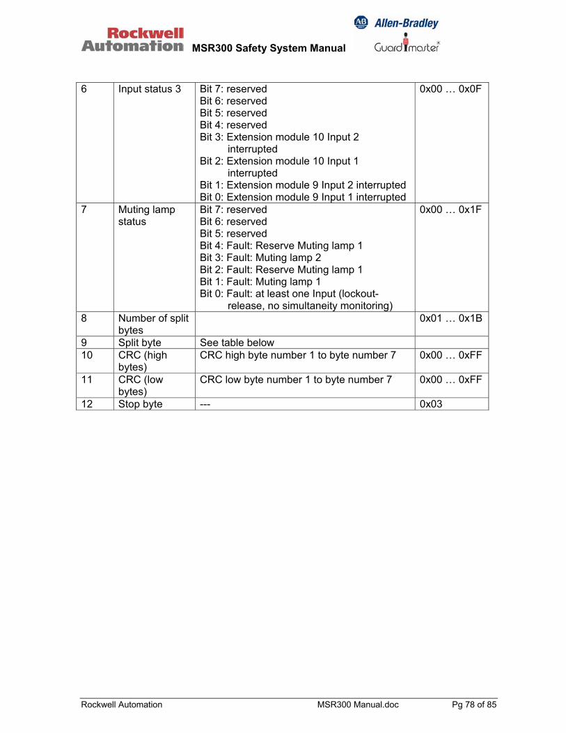
MSR300 Safety System Manual
Rockwell Automation MSR300 Manual.doc Pg 78 of 85
6 Input status 3 Bit 7: reserved
Bit 6: reserved Bit 5: reserved Bit 4: reserved Bit 3: Extension module 10 Input 2
interrupted Bit 2: Extension module 10 Input 1
interrupted Bit 1: Extension module 9 Input 2 interrupted Bit 0: Extension module 9 Input 1 interrupted
0x00 … 0x0F
7 Muting lamp status
Bit 7: reserved Bit 6: reserved Bit 5: reserved Bit 4: Fault: Reserve Muting lamp 1 Bit 3: Fault: Muting lamp 2 Bit 2: Fault: Reserve Muting lamp 1 Bit 1: Fault: Muting lamp 1 Bit 0: Fault: at least one Input (lockout-
release, no simultaneity monitoring)
0x00 … 0x1F
8 Number of split bytes
0x01 … 0x1B
9 Split byte See table below 10 CRC (high
bytes) CRC high byte number 1 to byte number 7 0x00 … 0xFF
11 CRC (low
bytes) CRC low byte number 1 to byte number 7 0x00 … 0xFF
12 Stop byte --- 0x03
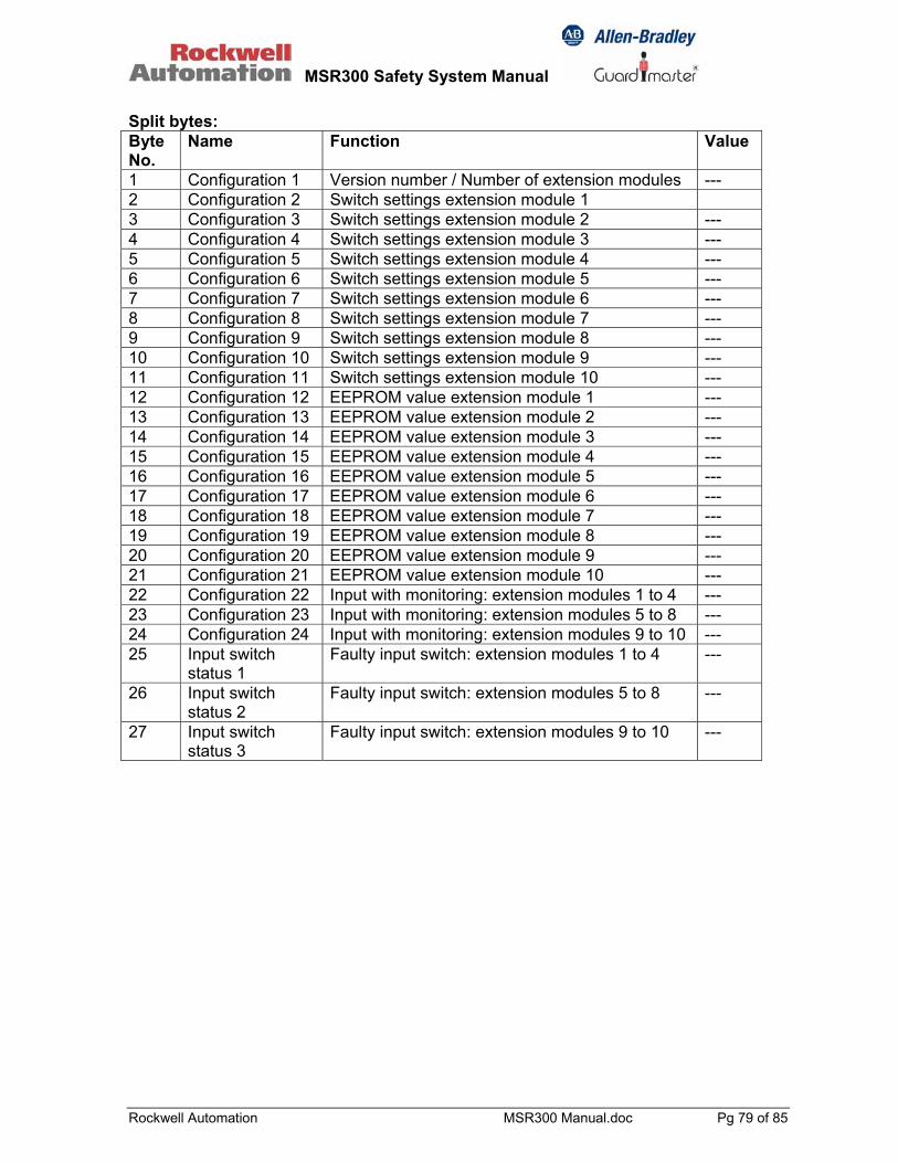
MSR300 Safety System Manual
Rockwell Automation MSR300 Manual.doc Pg 79 of 85
Split bytes: Byte No.
Name Function Value
1 Configuration 1 Version number / Number of extension modules --- 2 Configuration 2 Switch settings extension module 1 3 Configuration 3 Switch settings extension module 2 --- 4 Configuration 4 Switch settings extension module 3 --- 5 Configuration 5 Switch settings extension module 4 --- 6 Configuration 6 Switch settings extension module 5 --- 7 Configuration 7 Switch settings extension module 6 --- 8 Configuration 8 Switch settings extension module 7 --- 9 Configuration 9 Switch settings extension module 8 --- 10 Configuration 10 Switch settings extension module 9 --- 11 Configuration 11 Switch settings extension module 10 --- 12 Configuration 12 EEPROM value extension module 1 --- 13 Configuration 13 EEPROM value extension module 2 --- 14 Configuration 14 EEPROM value extension module 3 --- 15 Configuration 15 EEPROM value extension module 4 --- 16 Configuration 16 EEPROM value extension module 5 --- 17 Configuration 17 EEPROM value extension module 6 --- 18 Configuration 18 EEPROM value extension module 7 --- 19 Configuration 19 EEPROM value extension module 8 --- 20 Configuration 20 EEPROM value extension module 9 --- 21 Configuration 21 EEPROM value extension module 10 --- 22 Configuration 22 Input with monitoring: extension modules 1 to 4 --- 23 Configuration 23 Input with monitoring: extension modules 5 to 8 --- 24 Configuration 24 Input with monitoring: extension modules 9 to 10 --- 25 Input switch
status 1 Faulty input switch: extension modules 1 to 4 ---
26 Input switch status 2
Faulty input switch: extension modules 5 to 8 ---
27 Input switch status 3
Faulty input switch: extension modules 9 to 10 ---
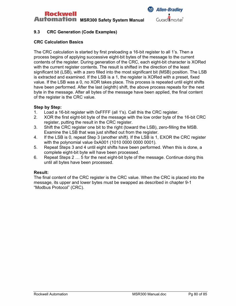
MSR300 Safety System Manual
Rockwell Automation MSR300 Manual.doc Pg 80 of 85
9.3 CRC Generation (Code Examples) CRC Calculation Basics The CRC calculation is started by first preloading a 16-bit register to all 1’s. Then a process begins of applying successive eight-bit bytes of the message to the current contents of the register. During generation of the CRC, each eight-bit character is XORed with the current register contents. The result is shifted in the direction of the least significant bit (LSB), with a zero filled into the most significant bit (MSB) position. The LSB is extracted and examined. If the LSB is a 1, the register is XORed with a preset, fixed value. If the LSB was a 0, no XOR takes place. This process is repeated until eight shifts have been performed. After the last (eighth) shift, the above process repeats for the next byte in the message. After all bytes of the message have been applied, the final content of the register is the CRC value. Step by Step: 1. Load a 16-bit register with 0xFFFF (all 1's). Call this the CRC register. 2. XOR the first eight-bit byte of the message with the low order byte of the 16-bit CRC
register, putting the result in the CRC register. 3. Shift the CRC register one bit to the right (toward the LSB), zero-filling the MSB.
Examine the LSB that was just shifted out from the register. 4. If the LSB is 0, repeat Step 3 (another shift). If the LSB is 1, EXOR the CRC register
with the polynomial value 0xA001 (1010 0000 0000 0001). 5. Repeat Steps 3 and 4 until eight shifts have been performed. When this is done, a
complete eight-bit byte will have been processed. 6. Repeat Steps 2 … 5 for the next eight-bit byte of the message. Continue doing this
until all bytes have been processed. Result: The final content of the CRC register is the CRC value. When the CRC is placed into the message, its upper and lower bytes must be swapped as described in chapter 9-1 “Modbus Protocol” (CRC).
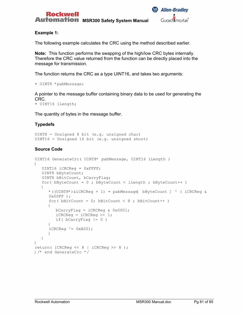
MSR300 Safety System Manual
Rockwell Automation MSR300 Manual.doc Pg 81 of 85
Example 1: The following example calculates the CRC using the method described earlier. Note: This function performs the swapping of the high/low CRC bytes internally. Therefore the CRC value returned from the function can be directly placed into the message for transmission. The function returns the CRC as a type UINT16, and takes two arguments: • UINT8 *pabMessage; A pointer to the message buffer containing binary data to be used for generating the CRC. • UINT16 iLength; The quantity of bytes in the message buffer. Typedefs UINT8 = Unsigned 8 bit (e.g. unsigned char) UINT16 = Unsigned 16 bit (e.g. unsigned short) Source Code UINT16 GenerateCrc( UINT8* pabMessage, UINT16 iLength ) { UINT16 iCRCReg = 0xFFFF; UINT8 bByteCount; UINT8 bBitCount, bCarryFlag; for( bByteCount = 0 ; bByteCount < iLength ; bByteCount++ ) { *((UINT8*)&iCRCReg + 1) = pabMessage[ bByteCount ] ^ ( iCRCReg & 0x00FF ); for( bBitCount = 0; bBitCount < 8 ; bBitCount++ ) { bCarryFlag = iCRCReg & 0x0001; iCRCReg = iCRCReg >> 1; if( bCarryFlag != 0 ) { iCRCReg ^= 0xA001; } } } return( iCRCReg << 8 | iCRCReg >> 8 ); }/* end GenerateCrc */

MSR300 Safety System Manual
Rockwell Automation MSR300 Manual.doc Pg 82 of 85
Example 2 This example uses another approach to calculate the CRC; All of the possible CRC values are pre-loaded into two arrays, which are simply indexed as the function increments through the message buffer. One array contains all of the 256 possible CRC values for the high byte of the 16-bit CRC field, and the other array contains all of the values for the low byte. Indexing the CRC in this way provides faster execution than would be achieved by calculating a new CRC value with each new character from the message buffer. Note: This function performs the swapping of the high/low CRC bytes internally. Therefore the CRC value returned from the function can be directly placed into the message for transmission. The function returns the CRC as a type UINT16, and takes two arguments: • UINT8 *pabMessage; A pointer to the message buffer containing binary data to be used for generating the CRC. • UINT16 iLength; The quantity of bytes in the message buffer. Typedefs UINT8 = Unsigned 8 bit (e.g. unsigned char) UINT16 = Unsigned 16 bit (e.g. unsigned short) Source Code UINT16 GenerateCrc( UINT8* pabMessage, UINT16 iLength ) { static UINT8 abCrcHi[] = { 0x00, 0xC1, 0x81, 0x40, 0x01, 0xC0, 0x80, 0x41, 0x01, 0xC0, 0x80, 0x41, 0x00, 0xC1, 0x81, 0x40, 0x01, 0xC0, 0x80, 0x41, 0x00, 0xC1, 0x81, 0x40, 0x00, 0xC1, 0x81, 0x40, 0x01, 0xC0, 0x80, 0x41, 0x01, 0xC0, 0x80, 0x41, 0x00, 0xC1, 0x81, 0x40, 0x00, 0xC1, 0x81, 0x40, 0x01, 0xC0, 0x80, 0x41, 0x00, 0xC1, 0x81, 0x40, 0x01, 0xC0, 0x80, 0x41, 0x01, 0xC0, 0x80, 0x41, 0x00, 0xC1, 0x81, 0x40, 0x01, 0xC0, 0x80, 0x41, 0x00, 0xC1, 0x81, 0x40, 0x00, 0xC1, 0x81, 0x40, 0x01, 0xC0, 0x80, 0x41, 0x00, 0xC1, 0x81, 0x40, 0x01, 0xC0, 0x80, 0x41, 0x01, 0xC0, 0x80, 0x41, 0x00, 0xC1, 0x81, 0x40, 0x00, 0xC1, 0x81, 0x40, 0x01, 0xC0, 0x80, 0x41, 0x01, 0xC0, 0x80, 0x41, 0x00, 0xC1, 0x81, 0x40, 0x01, 0xC0, 0x80, 0x41, 0x00, 0xC1, 0x81, 0x40, 0x00, 0xC1, 0x81, 0x40, 0x01, 0xC0, 0x80, 0x41, 0x01, 0xC0, 0x80, 0x41, 0x00, 0xC1, 0x81, 0x40, 0x00, 0xC1, 0x81, 0x40, 0x01, 0xC0, 0x80, 0x41, 0x00, 0xC1, 0x81, 0x40, 0x01, 0xC0, 0x80, 0x41, 0x01, 0xC0, 0x80, 0x41, 0x00, 0xC1, 0x81, 0x40, 0x00, 0xC1, 0x81, 0x40, 0x01, 0xC0, 0x80, 0x41, 0x01, 0xC0, 0x80, 0x41, 0x00, 0xC1, 0x81, 0x40, 0x01, 0xC0, 0x80, 0x41, 0x00, 0xC1, 0x81, 0x40, 0x00, 0xC1, 0x81, 0x40, 0x01, 0xC0, 0x80, 0x41, 0x00, 0xC1, 0x81, 0x40, 0x01, 0xC0, 0x80, 0x41, 0x01, 0xC0, 0x80, 0x41,
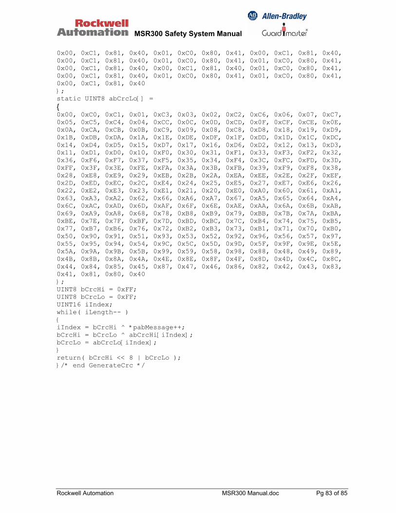
MSR300 Safety System Manual
Rockwell Automation MSR300 Manual.doc Pg 83 of 85
0x00, 0xC1, 0x81, 0x40, 0x01, 0xC0, 0x80, 0x41, 0x00, 0xC1, 0x81, 0x40, 0x00, 0xC1, 0x81, 0x40, 0x01, 0xC0, 0x80, 0x41, 0x01, 0xC0, 0x80, 0x41, 0x00, 0xC1, 0x81, 0x40, 0x00, 0xC1, 0x81, 0x40, 0x01, 0xC0, 0x80, 0x41, 0x00, 0xC1, 0x81, 0x40, 0x01, 0xC0, 0x80, 0x41, 0x01, 0xC0, 0x80, 0x41, 0x00, 0xC1, 0x81, 0x40 }; static UINT8 abCrcLo[] = { 0x00, 0xC0, 0xC1, 0x01, 0xC3, 0x03, 0x02, 0xC2, 0xC6, 0x06, 0x07, 0xC7, 0x05, 0xC5, 0xC4, 0x04, 0xCC, 0x0C, 0x0D, 0xCD, 0x0F, 0xCF, 0xCE, 0x0E, 0x0A, 0xCA, 0xCB, 0x0B, 0xC9, 0x09, 0x08, 0xC8, 0xD8, 0x18, 0x19, 0xD9, 0x1B, 0xDB, 0xDA, 0x1A, 0x1E, 0xDE, 0xDF, 0x1F, 0xDD, 0x1D, 0x1C, 0xDC, 0x14, 0xD4, 0xD5, 0x15, 0xD7, 0x17, 0x16, 0xD6, 0xD2, 0x12, 0x13, 0xD3, 0x11, 0xD1, 0xD0, 0x10, 0xF0, 0x30, 0x31, 0xF1, 0x33, 0xF3, 0xF2, 0x32, 0x36, 0xF6, 0xF7, 0x37, 0xF5, 0x35, 0x34, 0xF4, 0x3C, 0xFC, 0xFD, 0x3D, 0xFF, 0x3F, 0x3E, 0xFE, 0xFA, 0x3A, 0x3B, 0xFB, 0x39, 0xF9, 0xF8, 0x38, 0x28, 0xE8, 0xE9, 0x29, 0xEB, 0x2B, 0x2A, 0xEA, 0xEE, 0x2E, 0x2F, 0xEF, 0x2D, 0xED, 0xEC, 0x2C, 0xE4, 0x24, 0x25, 0xE5, 0x27, 0xE7, 0xE6, 0x26, 0x22, 0xE2, 0xE3, 0x23, 0xE1, 0x21, 0x20, 0xE0, 0xA0, 0x60, 0x61, 0xA1, 0x63, 0xA3, 0xA2, 0x62, 0x66, 0xA6, 0xA7, 0x67, 0xA5, 0x65, 0x64, 0xA4, 0x6C, 0xAC, 0xAD, 0x6D, 0xAF, 0x6F, 0x6E, 0xAE, 0xAA, 0x6A, 0x6B, 0xAB, 0x69, 0xA9, 0xA8, 0x68, 0x78, 0xB8, 0xB9, 0x79, 0xBB, 0x7B, 0x7A, 0xBA, 0xBE, 0x7E, 0x7F, 0xBF, 0x7D, 0xBD, 0xBC, 0x7C, 0xB4, 0x74, 0x75, 0xB5, 0x77, 0xB7, 0xB6, 0x76, 0x72, 0xB2, 0xB3, 0x73, 0xB1, 0x71, 0x70, 0xB0, 0x50, 0x90, 0x91, 0x51, 0x93, 0x53, 0x52, 0x92, 0x96, 0x56, 0x57, 0x97, 0x55, 0x95, 0x94, 0x54, 0x9C, 0x5C, 0x5D, 0x9D, 0x5F, 0x9F, 0x9E, 0x5E, 0x5A, 0x9A, 0x9B, 0x5B, 0x99, 0x59, 0x58, 0x98, 0x88, 0x48, 0x49, 0x89, 0x4B, 0x8B, 0x8A, 0x4A, 0x4E, 0x8E, 0x8F, 0x4F, 0x8D, 0x4D, 0x4C, 0x8C, 0x44, 0x84, 0x85, 0x45, 0x87, 0x47, 0x46, 0x86, 0x82, 0x42, 0x43, 0x83, 0x41, 0x81, 0x80, 0x40 }; UINT8 bCrcHi = 0xFF; UINT8 bCrcLo = 0xFF; UINT16 iIndex; while( iLength-- ) { iIndex = bCrcHi ^ *pabMessage++; bCrcHi = bCrcLo ^ abCrcHi[iIndex]; bCrcLo = abCrcLo[iIndex]; } return( bCrcHi << 8 | bCrcLo ); }/* end GenerateCrc */
MSR300 Safety System Manual
Rockwell Automation MSR300 Manual.doc Pg 84 of 85
Annexure Product Warranty and Disclaimer The following is a partial statement of the product warranty and disclaimer, and is subject to the warranty terms and disclaimer included in the standard terms of sale/contract of the Seller. 1. Warranty (a). Allen-Bradley / Rockwell Automation Hardware: Seller warrants that new hardware Products furnished hereunder will be free from defects in material, workmanship and design for a period of one (1) year from the date of invoice from Seller or its appointed distributor, as the case may be. Repaired or replacement Products provided as a result of this warranty subparagraph are similarly warranted for a period of six (6) months from the date of shipment to Buyer or the remainder of the original warranty term for that particular Product, whichever is longer. (b). Allen-Bradley and Rockwell Software Branded Software and Firmware: Unless otherwise provided in a Seller or third party license, Seller warrants that standard software or firmware Products furnished hereunder, when used with Seller-specified hardware, will perform in accordance with published specifications prepared, approved, and issued by Seller for a period of one (1) year from the date of invoice from Seller or its appointed distributor, as the case may be. Seller makes no representation or warranty, express or implied, that the operation of the software or firmware Products will be uninterrupted or error free, or that the functions contained therein will meet or satisfy Buyer's intended use or requirements. (c). Remedies: Remedies under the above warranties will be limited, at Seller’s option, to the replacement, repair, re-performance or modification of, or issuance of a credit for the purchase price, of the Products involved, and where applicable, only after the return of such Products pursuant to Seller's instructions. Replacement Products may be new, remanufactured, refurbished or reconditioned at Seller’s discretion. Buyer requested on-site warranty service (consisting of time, travel and expenses related to such services) will be at Buyer’s expense. The foregoing will be the exclusive remedies for any breach of warranty or breach of contract arising therefrom. (d). General: Warranty satisfaction is available only if (a) Seller is provided prompt written notice of the warranty claim and (b) Seller’s examination discloses that any alleged defect has not been caused by misuse; neglect; improper installation, operation, maintenance, repair, alteration or modification by other than Seller; accident; or unusual deterioration or degradation of the Products or parts thereof due to physical environment or electrical or electromagnetic noise environment. (e). Exclusion of Other Warranties: The above warranties are in lieu of all other warranties and conditions, whether expressed, implied or statutory, including implied warranties of merchantability or fitness for a particular use, or performance or application warranties, to the fullest extent permitted by applicable law. Rights under the above warranties (subject to noted
MSR300 Safety System Manual
Rockwell Automation MSR300 Manual.doc Pg 85 of 85
limitations) extend to buyer’s customers if buyer is a seller-appointed distributor for the products. 2. Disclaimer And Limitation Of Liability To the fullest extent permitted by applicable law, seller will not be liable for any business interruption or loss of profit, revenue, materials, anticipated savings, data, contract, goodwill or the like (whether direct or indirect in nature) or for any other form of incidental, indirect or consequential damages of any kind. Seller's maximum cumulative liability relative to all other claims and liabilities, including obligations under any indemnity, whether or not insured, will not exceed the cost of the product(s) giving rise to the claim or liability. Seller disclaims all liability relative to gratuitous information or assistance provided by, but not required of seller hereunder. Any action against seller must be brought within eighteen (18) months after the cause of action accrues. These disclaimers and limitations of liability will apply regardless of any other contrary provision hereof and regardless of the form of action, whether in contract, tort (including negligence and strict liability) or otherwise, and further will extend to the benefit of seller’s vendors, appointed distributors and other authorized resellers as third-party beneficiaries. Each provision hereof which provides for a limitation of liability, disclaimer of warranty or condition or exclusion of damages is severable and independent of any other provision and is to be enforced as such. Drg No: 95302171/ Issue No: 3 Jan 06