msd coolant temperature lazer gauge, 2 5/8 pn...
TRANSCRIPT
MSD IGNITION • 1490 HENRY BRENNAN DR., EL PASO, TEXAS 79936 • (915) 857-5200 • FAX (915) 857-3344
MSD Coolant TemperatureLazer Gauge, 2 5/8"
PN 46241
WARNING: When installing the Lazer Coolant Temperature Gauge, disconnect the battery cables. When disconnecting, always remove the negative cable first and re-install it last.
FEATURES
The MSD Lazer Coolant Temperature Gauge can display transmission temperatures from 50° to 250°F with accuracy of ± 6°F across the range. The gauge employs a single 270° arc display with a clockwise sweep. It features a programmable peak temperature alarm that will flash the portion of the arc above the programmed high temp value and change gauge back lighting from white to red. The alarm point is easily adjusted by the user using the touch face programming capability. The gauge will also display the peak coolant temperature reached with a solid dot of light.
1 - Serial Adapter Cable1 - Parts Bag1 - Sending Unit, MSD PN 2310
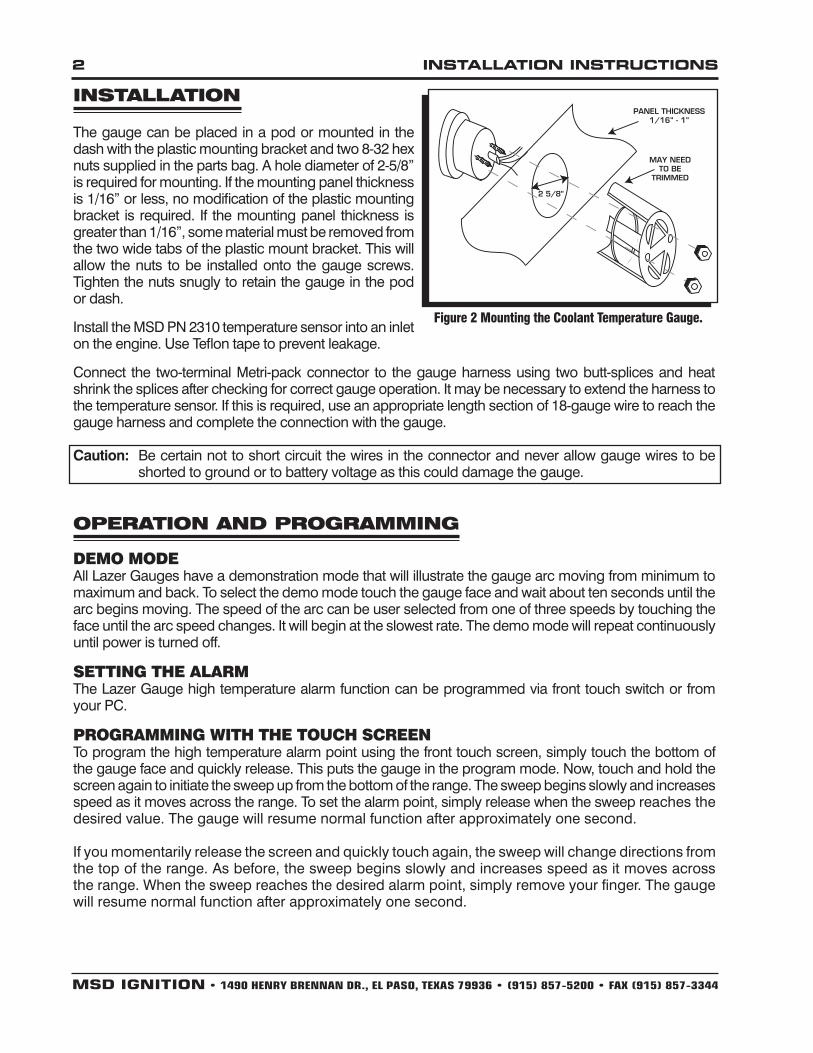
Figure 1 Wiring the Coolant Temperature Gauge
WIRING
RED Connects to switched 12 volts.
BLACK Connects to Ground.
WHITE Alarm output, switched to Ground; 1 amp max load.
BLUE Connects to Temperature sender + (positive).
GREEN Connects to Temperature sender – (ground).
6-pin Connector
Temperature Sensor, MSD PN 2310Two-terminal Metri-pack connector to Blue and Green Gauge wires.
RS 232 TO PCTO SWITCHED
12 VOLTSPC PORT
GREEN (-)
BLUE (+)SENSOR
MSD PN 2310
RED
WHITE
BLACK
TO GROUND
TO OPTIONALALARM OUTPUT(SWITCH TO GROUND)
PN 46241
Parts Included: 1 – Adapter Cable1 - Gauge1 - Wiring Harness1 - MSD Lazer Software on CD ROM
� INSTALLATIONINSTRUCTIONS
MSD IGNITION • 1490 HENRY BRENNAN DR., EL PASO, TEXAS 79936 • (915) 857-5200 • FAX (915) 857-3344
INSTALLATION
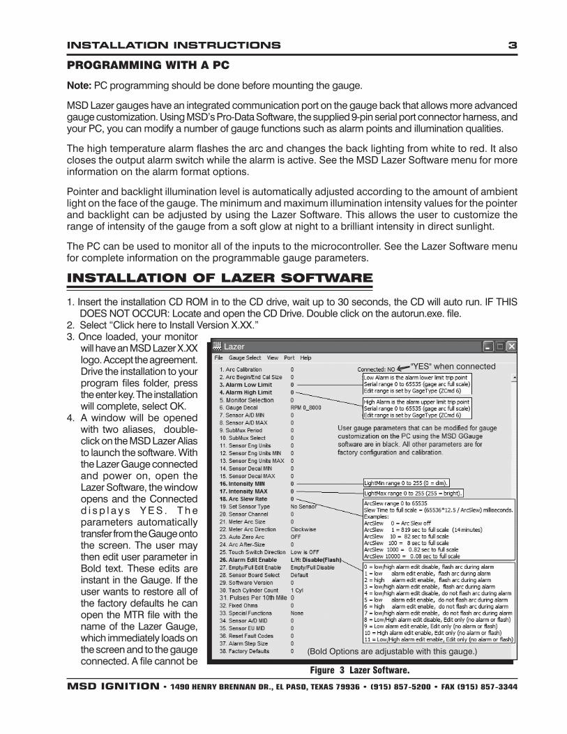
The gauge can be placed in a pod or mounted in the dash with the plastic mounting bracket and two 8-32 hex nuts supplied in the parts bag. A hole diameter of 2-5/8” is required for mounting. If the mounting panel thickness is 1/16” or less, no modification of the plastic mounting bracket is required. If the mounting panel thickness is greater than 1/16”, some material must be removed from the two wide tabs of the plastic mount bracket. This will allow the nuts to be installed onto the gauge screws. Tighten the nuts snugly to retain the gauge in the pod or dash.
Install the MSD PN 2310 temperature sensor into an inlet on the engine. Use Teflon tape to prevent leakage.
Connect the two-terminal Metri-pack connector to the gauge harness using two butt-splices and heat shrink the splices after checking for correct gauge operation. It may be necessary to extend the harness to the temperature sensor. If this is required, use an appropriate length section of 18-gauge wire to reach the gauge harness and complete the connection with the gauge.
Caution: Be certain not to short circuit the wires in the connector and never allow gauge wires to be shorted to ground or to battery voltage as this could damage the gauge.
OPERATION AND PROGRAMMING
Demo moDeAll Lazer Gauges have a demonstration mode that will illustrate the gauge arc moving from minimum to maximum and back. To select the demo mode touch the gauge face and wait about ten seconds until the arc begins moving. The speed of the arc can be user selected from one of three speeds by touching the face until the arc speed changes. It will begin at the slowest rate. The demo mode will repeat continuously until power is turned off.
SettIng the AlArmThe Lazer Gauge high temperature alarm function can be programmed via front touch switch or from your PC.
ProgrAmmIng wIth the touch ScreenTo program the high temperature alarm point using the front touch screen, simply touch the bottom of the gauge face and quickly release. This puts the gauge in the program mode. Now, touch and hold the screen again to initiate the sweep up from the bottom of the range. The sweep begins slowly and increases speed as it moves across the range. To set the alarm point, simply release when the sweep reaches the desired value. The gauge will resume normal function after approximately one second.
If you momentarily release the screen and quickly touch again, the sweep will change directions from the top of the range. As before, the sweep begins slowly and increases speed as it moves across the range. When the sweep reaches the desired alarm point, simply remove your finger. The gauge will resume normal function after approximately one second.
Figure 2 Mounting the Coolant Temperature Gauge.
PANEL THICKNESS1/16” - 1”
MAY NEEDTO BE
TRIMMED
2 5/8”
INSTALLATIONINSTRUCTIONS �
MSD IGNITION • 1490 HENRY BRENNAN DR., EL PASO, TEXAS 79936 • (915) 857-5200 • FAX (915) 857-3344
ProgrAmmIng wIth A Pc
Note: PC programming should be done before mounting the gauge.
MSD Lazer gauges have an integrated communication port on the gauge back that allows more advanced gauge customization. Using MSD’s Pro-Data Software, the supplied 9-pin serial port connector harness, and your PC, you can modify a number of gauge functions such as alarm points and illumination qualities.
The high temperature alarm flashes the arc and changes the back lighting from white to red. It also closes the output alarm switch while the alarm is active. See the MSD Lazer Software menu for more information on the alarm format options.
Pointer and backlight illumination level is automatically adjusted according to the amount of ambient light on the face of the gauge. The minimum and maximum illumination intensity values for the pointer and backlight can be adjusted by using the Lazer Software. This allows the user to customize the range of intensity of the gauge from a soft glow at night to a brilliant intensity in direct sunlight.
The PC can be used to monitor all of the inputs to the microcontroller. See the Lazer Software menu for complete information on the programmable gauge parameters.
INSTALLATION OF LAzER SOFTwARE
1. Insert the installation CD ROM in to the CD drive, wait up to 30 seconds, the CD will auto run. IF THIS DOES NOT OCCUR: Locate and open the CD Drive. Double click on the autorun.exe. file.
2. Select “Click here to Install Version X.XX.”3. Once loaded, your monitor
will have an MSD Lazer X.XX logo. Accept the agreement. Drive the installation to your program files folder, press the enter key. The installation will complete, select OK.
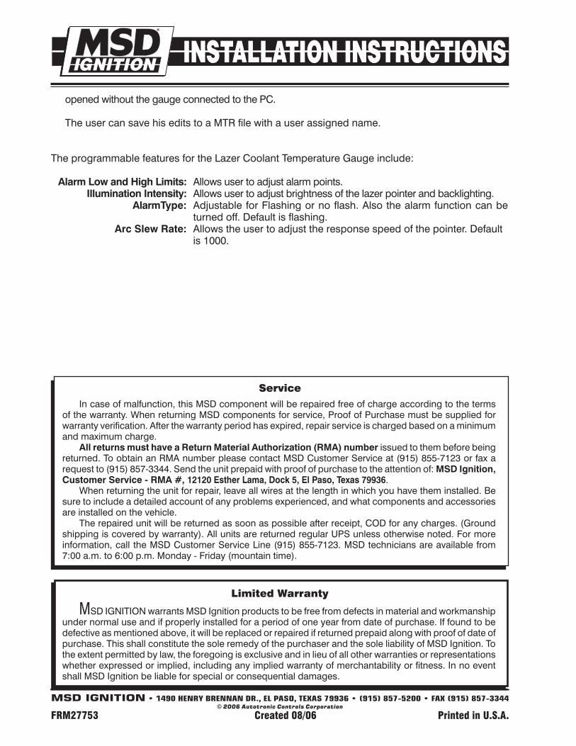
4. A window will be opened with two aliases, double-click on the MSD Lazer Alias to launch the software. With the Lazer Gauge connected and power on, open the Lazer Software, the window opens and the Connected d i s p l a y s Y E S . T h e parameters automatically transfer from the Gauge onto the screen. The user may then edit user parameter in Bold text. These edits are instant in the Gauge. If the user wants to restore all of the factory defaults he can open the MTR file with the name of the Lazer Gauge, which immediately loads on the screen and to the gauge connected. A file cannot be
"YES" when connected
(Bold Options are adjustable with this gauge.)
Figure 3 Lazer Software.
Lazer
opened without the gauge connected to the PC.
The user can save his edits to a MTR file with a user assigned name.
The programmable features for the Lazer Coolant Temperature Gauge include:
AlarmLowandHighLimits: Allows user to adjust alarm points. IlluminationIntensity: Allows user to adjust brightness of the lazer pointer and backlighting. AlarmType: Adjustable for Flashing or no flash. Also the alarm function can be turned off. Default is flashing. ArcSlewRate: Allows the user to adjust the response speed of the pointer. Default is 1000.
MSD IGNITION • 1490 HENRY BRENNAN DR., EL PASO, TEXAS 79936 • (915) 857-5200 • FAX (915) 857-3344© 2006 Autotronic Controls Corporation
FRM27753 Created 08/06 Printed in U.S.A.
limited warranty
MSD IGNITION warrants MSD Ignition products to be free from defects in material and workmanship under normal use and if properly installed for a period of one year from date of purchase. If found to be defective as mentioned above, it will be replaced or repaired if returned prepaid along with proof of date of purchase. This shall constitute the sole remedy of the purchaser and the sole liability of MSD Ignition. To the extent permitted by law, the foregoing is exclusive and in lieu of all other warranties or representations whether expressed or implied, including any implied warranty of merchantability or fitness. In no event shall MSD Ignition be liable for special or consequential damages.
ServiceIn case of malfunction, this MSD component will be repaired free of charge according to the terms
of the warranty. When returning MSD components for service, Proof of Purchase must be supplied for warranty verification. After the warranty period has expired, repair service is charged based on a minimum and maximum charge.
AllreturnsmusthaveaReturnMaterialAuthorization(RMA)numberissued to them before being returned. To obtain an RMA number please contact MSD Customer Service at (915) 855-7123 or fax a request to (915) 857-3344. Send the unit prepaid with proof of purchase to the attention of: MSDIgnition,CustomerService-RMA#,12120EstherLama,Dock5,ElPaso,Texas79936.
When returning the unit for repair, leave all wires at the length in which you have them installed. Be sure to include a detailed account of any problems experienced, and what components and accessories are installed on the vehicle.
The repaired unit will be returned as soon as possible after receipt, COD for any charges. (Ground shipping is covered by warranty). All units are returned regular UPS unless otherwise noted. For more information, call the MSD Customer Service Line (915) 855-7123. MSD technicians are available from 7:00 a.m. to 6:00 p.m. Monday - Friday (mountain time).