mrp - titan - bdhmedical.nl · the mrp-titan system is designed to allow subsequent corrections to...
TRANSCRIPT

INSTRUMENTATION TECHNIQUE
MRP - TITANTHE MODULAR REVISION PROSTHESIS FOR ALL SITUATIONS IN EVERYDAY CLINICAL PRACTICE

1. PRODUCT DESCRIPTION
Preface 4System Concept at a Glance 4Design Characteristics: Implant Anchoring Stem 5Design Characteristics: Implant Neck Segment 6Design Characteristics: Implant System 7Pretensioning the Taper Connection to a Defined Torque 8Controlled Release of the Taper Connection 9Indications 9
2. INSTRUMENTATION TECHNIQUE
Preoperative Planning 11
Patient Positioning and Approaches 11
Preparing the Bone-Implant Interface 12 Preparation in Primary Arthroplasty 12 Preparation in Revision Arthroplasty 13 Trial Assembly 15 Selecting the Diameter of the TRIAL Anchoring Stem 15 Assembling the Impactor/Extractor 16 Determining Implant Length 19 Placing the Neck Segment 20 Disconnecting the Trial Assembly 23 Removing the TRIAL Anchoring Stem 26
Placing the Definitive Implant 27 Placing the Anchoring Stem 27 Placing the Neck Segment 28 Pretensioning the Definitive Implant 29 Sealing the Neck Segment 38 Securing the Prosthetic Trochanter 38 Placing the Definitive Femoral Ball 39
Postoperative Disassembly 40 Releasing the Pretensioned Components and Disassembling the Implant 40
Removing the Definitive Implant 44 Removal 44 Removing the Entire System with the Slap Hammer 46 Removing the Anchoring Stem with the Slap Hammer 48
3. SUPPLEMENTARY PRODUCTS Impaction Grafting System (IGS) 51 MRP-TITAN mdV Aiming Device 52 MRP-TITAN pFE Proximal Femur Replacement 53 KAM-TITAN 54 MRS-TITAN and MRS-TITAN Comfort 55
Table of Contents

MRP - TITAN PRODUCT DESCRIPTION
4 Instrumentation Technique – MRP - TITAN
Product Description
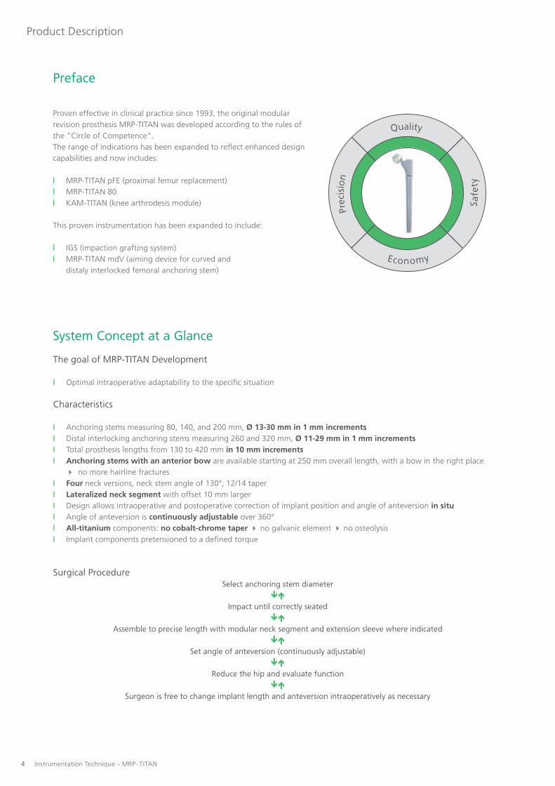
Proven effective in clinical practice since 1993, the original modular revision prosthesis MRP-TITAN was developed according to the rules of the "Circle of Competence".The range of indications has been expanded to reflect enhanced design capabilities and now includes:
| MRP-TITAN pFE (proximal femur replacement)| MRP-TITAN 80| KAM-TITAN (knee arthrodesis module)
This proven instrumentation has been expanded to include:
| IGS (impaction grafting system)| MRP-TITAN mdV (aiming device for curved and distaly interlocked femoral anchoring stem)
System Concept at a Glance
The goal of MRP-TITAN Development
| Optimal intraoperative adaptability to the specific situation
Characteristics
| Anchoring stems measuring 80, 140, and 200 mm, Ø 13-30 mm in 1 mm increments| Distal interlocking anchoring stems measuring 260 and 320 mm, Ø 11-29 mm in 1 mm increments | Total prosthesis lengths from 130 to 420 mm in 10 mm increments| Anchoring stems with an anterior bow are available starting at 250 mm overall length, with a bow in the right place no more hairline fractures| Four neck versions, neck stem angle of 130°, 12/14 taper| Lateralized neck segment with offset 10 mm larger| Design allows intraoperative and postoperative correction of implant position and angle of anteversion in situ| Angle of anteversion is continuously adjustable over 360°| All-titanium components: no cobalt-chrome taper no galvanic element no osteolysis| Implant components pretensioned to a defined torque
Surgical ProcedureSelect anchoring stem diameter
Impact until correctly seated
Assemble to precise length with modular neck segment and extension sleeve where indicated
Set angle of anteversion (continuously adjustable)
Reduce the hip and evaluate function
Surgeon is free to change implant length and anteversion intraoperatively as necessary
Preface
Prec
isio
n
Quality
Economy
Safe
ty

Instrumentation Technique – MRP - TITAN 5
Product Description
Design Characteristics: Implant Anchoring Stem
With 8 longitudinal ribs arranged in a stellate cross section, an integral gradient angle, and anchoring stem thicknesses availa-ble in 1 mm increments, the MRP-TITAN anchoring stem design ensures immediate stable cementless fixation.
The parabolic longitudinal ribs give the implant excellent initial stability and high fracture strength. The design also spares cancellous bone and thus preserves the arterial supply within the femur. This promotes solid bony ingrowth over a broad area for biologic fixation of the implant.
The titanium alloys TiAl6Nb7 and TiAl6V4 were selected as the material for the implant. Both exhibit high strength and excel-lent biocompatibility. The surfaces in contact with bone have also been shot peened with corundum (40 - 60 μm).
A uniform taper on the end of the anchoring stem makes it possible to use the anchoring stem in combination with neck seg-ments of different lengths and designs. Anteversion is continuously adjustable through 360°, enabling the surgeon to achieve optimal stem placement. Anteversion can be adjusted as required without any limitation.
MRP-TITAN mdV (Tapered, 2 mm slope)
MRP-TITAN 80 (Tapered, 7 mm slope)
+2 +2
Nominal diameter
Nominal diameter
MRP-TITAN Standard(Tapered, 6 mm slope)
+2
-4
+2
Nominal diameter
-4
80
+2
-5
Nominal diameter
140 200 260 320
The TRIAL Anchoring Stems are distinguished from the definitive anchoring stems by their smooth surface and by a radiogra-phically visible notch on the proximal end of the anchoring stem.

6 Instrumentation Technique – MRP - TITAN
Product Description
Design Characteristics: Implant Neck Segment
Different versions of neck segments are available for the modular MRP-TITAN anchoring stems.
The standardized inner and outer tapers of the neck segments allow them to be used in any combination. The precision fit of the taper connection is ensured by a special inspection and testing process.
With fin Standard, neck segment angle of 130° Thick, neck segment angle of 130°
The difference between these two versions of the neck segment is their volume. The larger volume of the thick neck segment makes it suitable for filling larger proximal femoral defects.
Without fin Standard, neck segment angle of 130°
Without fin Lateralized, neck segment angle of 123.5°
The lateralized neck segment allows 10 mm more lateralization of the leg than the standard neck segment.
For trochanter segment Large, neck segment angle of 130° Small, neck segment angle of 130°
This version can completely reconstruct the proximal femur where extreme defects are present or following tumor surgery.

Instrumentation Technique – MRP - TITAN 7
Product Description
Design Characteristics: Implant System
A major goal of surgery is to precisely obtain the desired leg length. Therefore, different versions of neck segments (S = 50 mm, M = 60 mm, L = 70 mm) are available for the modular MRP-TITAN system. An extension sleeve (30 mm) available in various diameters can also be used.
The various different components (anchoring stem, neck segment, extension sleeve) can be combined intraoperatively. This makes it possible to determine the exact length required and then test and place the implant. The implant can be assembled in lengths from 130 to 420 mm in 10 mm increments.
Always use only one extension sleeve. Every diameter of extension sleeve can be used with every diameter of anchoring stem.
! NOTE
The systems patented taper connection is also continuously adjustable through 360°, allowing the surgeon to select any desired angle of anteversion.
This minimizes the risk of dislocation and guarantees a total arthroplasty solution with long-term mechanical stability.
MRP-TITAN 80130 - 180 mm
MRP-TITAN 140190 - 240 mm
MRP-TITAN 200250 - 300 mm
MRP-TITAN 260310 - 360 mm
MRP-TITAN 320370 - 420 mm
S = 50 mm M = 60 mm L = 70 mm SH = 80 mm MH = 90 mm LH = 100 mm

8 Instrumentation Technique – MRP - TITAN
Product Description
Pretensioning the Taper Connection to a Defined Torque
Because a prosthesis is subjected to dynamic loads as well as static loads it is not enough to simply place the components in apposition or insert them into each other.
In order to achieve a permanent taper connection that resists torsional stresses, the MRP-TITAN system is first pretensioned to a defined torque with the Torsionfree Preloading Instrument (TOV). Then the prosthesis is secured by screwing it together with a torque of 25 Nm.
Several requirements have driven the development of the Torsionfree Preloading Instrument (TOV):
| Minimizing transverse forces and their influence on the Guide Rod and pretensioning procedure| Optimizing the connection strength and seating of the taper connection| Simplifying intraoperative assembly of the taper connection| Reproducible pretensioning| Sturdy design to facilitate processing
The innovative Torsionfree Preloading Instrument (TOV) has several advantages over all other common pretensioning techniques:
| Connection strength is increased by about 30%| The design ensures identical force application in every case to guarantee the desired prestress| The required pretensioning of the taper connection is achieved with purely axial loading| The taper components are optimally guided while making the connection
For the surgeon this means:
| About 40% less manual force is required to pretension the construct, thus simplifying the surgical technique| No great effort is required to release the instruments after the pretensioning procedure| The pretensioned taper components are easily released during the consolidation phase| Components are easily retightened
Reliable, permanent stability of the assembly is ensured only when the screw M6 is used.
! NOTE
"This rigorous further development is our contribution to your patients' safety."

Instrumentation Technique – MRP - TITAN 9
Product Description
Controlled Release of the Taper Connection
The MRP-TITAN system is designed to allow subsequent corrections to the implanted prosthesis should subsidence or a tendency to dislocate be detected intraoperatively or immediately postoperatively.
A separating instrument facilitates controlled release of the connections between the anchoring stem, extension sleeve, and neck segment. This gives the surgeon the option of placing a longer neck segment or readjusting the anteversion. The great advantage of this is that the implant stem can be left in situ. This avoids the risk of additional injuries to the femur from extrac-ting the anchoring stem and impacting a new stem.
The degree of activity or body weight of the patient may cause additional settling of the components, which can hamper the separation of the implant.
PETER BREHM GmbH can provide an additionally reinforced molding instrument for subsequent revision of the endoprosthesis.
! NOTE
I Congenital or acquired hip joint defectsI Degenerative, post-traumatic, rheumatic arthritis / arthrosisI Joint replacement (revision) already carried out and worn or in case of failed surgeryI Defect of the geometric rotation centerI Defects or malfunctions of the hip jointI Revisions with extensive bone resectionI Bone loss due to traumaI Extensive loss of bone materialI Severe deformities (e.g. osteomyelitis)I Coxa vara and Coxa valgaI Osteosarcoma and metastases
The additional module MRP-TITAN pFE is used for bone resection / bone loss.
INDICATIONS

MRP - TITANINSTRUMENTATION TECHNIQUE

0 mm
50 mm
100 mm
130 mm
140 mm
150 mm
160 mm
170 mm
180 mm
190 mm
200 mm
S
L
MH
M
SH
LH
neck segment
Ø 28 mm
M S
L
Ø 13 - Ø 25
Instrumentation Technique – MRP - TITAN 11
Instrumentation Technique
01
Preoperative Planning
The goal of total arthroplasty is the optimum anatomic reconstruction of the affected joint.
The first step is to determine the center of rotation of the affected joint. Preoperative planning begins with the evaluation of the size and placement of the acetabular compo-nent based on the radiograph. The next step is to determine the stem size and position required to achieve identical leg length with optimum initial stability. The size should be selected to ensure that at least one-third of the ribbed structure is firmly seated in the bone. The center of the femoral ball lies about level with the apex of the greater trochanter. Ideal-ly, the center of the femoral ball will correspond to the center of rotation of the acetabular component and leg length will be equal.
It is advisable to obtain radiographs of the hip in two planes (using a long imaging plate).
Radiographic magnification, scale 1.16:1
02
Patient Positioning and Approaches
This manual of surgical technique does not describe any particular approach for the MRP-TITAN. The surgeon can opt for any preferred approach with the patient in a lateral or supine position. If the patient is positioned supine, the hip must be able to move freely.

12 Instrumentation Technique – MRP - TITAN
Instrumentation Technique
Preparing the Bone-Implant Interface
Initial stability is an essential requirement for the success of total arthroplasty. With cementless implants, this is achieved with press-fit fixation. The implant and the bone should have good contact over a broad area.
Preparation in Primary Arthroplasty
03
Femoral Neck OsteotomyA lateral or posterior approach is used to expose the hip joint. Then the femoral neck is exposed with Hohman retractors with the hip dislocated. The osteotomy of the neck is then performed with an oscillating saw. The resection line on the femoral neck is determined according to preoperative planning.
04
Opening the Femoral CanalThe femoral canal is opened with a sharp rasp. The point of entry of the instrument usually lies in the middle of the cancell-ous osteotomy surface of the femoral neck. This rasp is then impacted axially, i. e. along the axis of the femoral shaft with a twisting motion. This creates a distal path for the subsequent reamers. In hard cancellous bone, the canal is first opened with a 10-mm box osteotome which is impacted into the central metaphyseal bone.
Where straight anchoring stem implants are used, it will be necessary to resect cortical bone at the apex of the greater trochanter. Otherwise it will not be possible to properly center the straight anchoring stem implant, especially in hard bone. The Rasp MRP-TITAN 80 mm may be used for this purpose.
Instrumentation Technique – MRP - TITAN 13
Instrumentation Technique
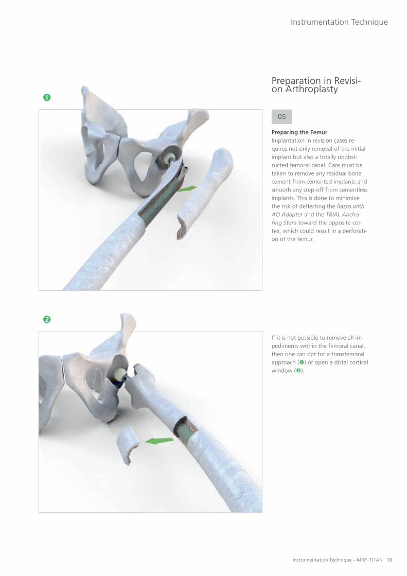
Preparation in Revisi-on Arthroplasty
05
Preparing the FemurImplantation in revision cases re-quires not only removal of the initial implant but also a totally unobst-ructed femoral canal. Care must be taken to remove any residual bone cement from cemented implants and smooth any step-off from cementless implants. This is done to minimize the risk of deflecting the Rasps with AO Adapter and the TRIAL Ancho-ring Stem toward the opposite cor-tex, which could result in a perforati-on of the femur.
If it is not possible to remove all im-pediments within the femoral canal, then one can opt for a transfemoral approach () or open a distal cortical window ().

14 Instrumentation Technique – MRP - TITAN
Instrumentation Technique
Preparing the Bone-Implant Interface
Preparation of the implant bed will vary depending on whether a straight or curved MRP-TITAN anchoring stem is used.
06
Curved anchoring stemsThe curvature of the femur and the anchoring stem requires the use of flexible reamers to prepare the medullary canal when using the 200, 260, and 320 mm curved anchoring stems. These reamers are introduced over an intramedullary guidewire. The femoral canal is machined with Drill Heads of successively larger diameters (in increments of 0,5 - 1 mm). This continues until the flexible reamer is in contact with the bone in a full circle over a distance of 70-100 mm. This will be indicated by the clear high-pitched sound of the cortex. Fluoroscopy must verify that the reamer remains centered in the medullary canal so that it will not perforate the cortex.
07
Straight anchoring stemsWhere straight anchoring stems are used, it is recommended to prepare the medullary canal with the straight Rasps with AO Adapter. These rasps are suitable for use with the 80 mm,140 mm, and 200 mm straight anchoring stems. The implant bed is reamed incrementally. The proper implant diameter is achieved when increased force is required to rotate the Rasp with AO Adapter. The implant length can be read from the scale on the instrument. The apex of the greater trochanter is used as the point of reference. It must align with the mark (center of hip rotation).

Instrumentation Technique – MRP - TITAN 15
Instrumentation Technique
Trial Assembly
08
Selecting the Diameter of the TRIAL Anchoring StemThe diameter of the last Rasp with AO Adapter used is selected as the initial diameter of the straight TRIAL Anchoring Stems. Then the diame-ters of the TRIAL Anchoring Stems are successively increased in 1 mm increments until the TRIAL Anchoring Stem is well seated at the desired location.
If the femur was prepared with fle-xible reamers, it is recommended to begin with the same TRIAL Ancho-ring Stem diameter as the reamer or the next smaller diameter. This is done because a narrower TRIAL Anchoring Stem can be used to palpate the physiologic curvature of the femur. Then the stem diameters are successively increased in 1 mm increments until a good interference fit is achieved.

16 Instrumentation Technique – MRP - TITAN
Instrumentation Technique
Trial Assembly
09
Assembling the Impactor/ExtractorThe seating instrument of the mo-dular MRP-TITAN prosthesis consists of the Handle for Prosthesis Inserter / Remover, a Knurled Screw S, and the Guide Rod. On the ends of the Guide Rod there are two threaded sections of different lengths. This defines where each threaded section can be used.
Short threading = anchoring stem and TRIAL Anchoring Stem
Long threading = Knurled Screw
Ensure that the Guide Rod is completely screwed into the TRIAL Anchoring Stem either manually or using a Socket Wrench SW 3,5.
! NOTE
Instrumentation Technique – MRP - TITAN 17
Instrumentation Technique
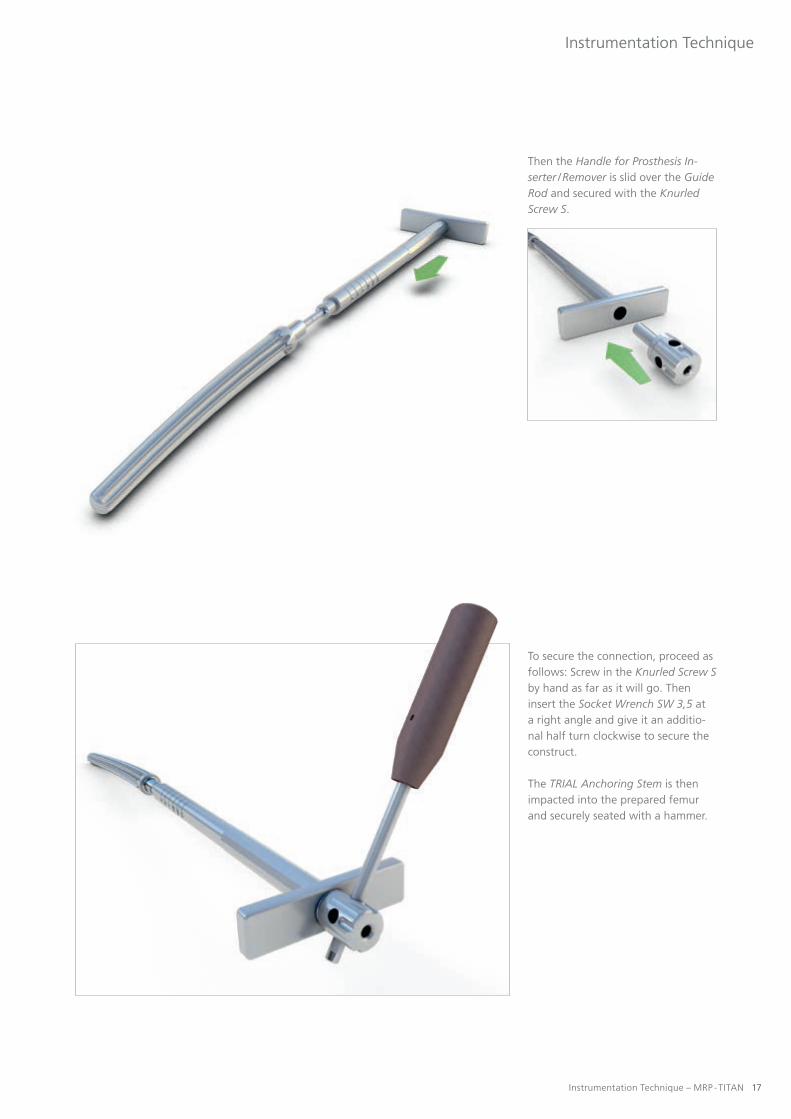
Then the Handle for Prosthesis In-serter / Remover is slid over the Guide Rod and secured with the Knurled Screw S.
To secure the connection, proceed as follows: Screw in the Knurled Screw Sby hand as far as it will go. Then insert the Socket Wrench SW 3,5 at a right angle and give it an additio-nal half turn clockwise to secure the construct.
The TRIAL Anchoring Stem is then impacted into the prepared femur and securely seated with a hammer.
18 Instrumentation Technique – MRP - TITAN
Instrumentation Technique
Trial Assembly
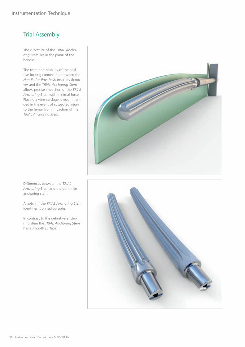
The curvature of the TRIAL Ancho-ring Stem lies in the plane of the handle.
The rotational stability of the posi-tive-locking connection between the Handle for Prosthesis Inserter / Remo-ver and the TRIAL Anchoring Stem allows precise impaction of the TRIAL Anchoring Stem with minimal force. Placing a wire cerclage is recommen-ded in the event of suspected injury to the femur from impaction of the TRIAL Anchoring Stem.
Differences between the TRIAL Anchoring Stem and the definitive anchoring stem:
A notch in the TRIAL Anchoring Stem identifies it on radiographs.
In contrast to the definitive ancho-ring stem the TRIAL Anchoring Stem has a smooth surface.
Instrumentation Technique – MRP - TITAN 19
Instrumentation Technique
10
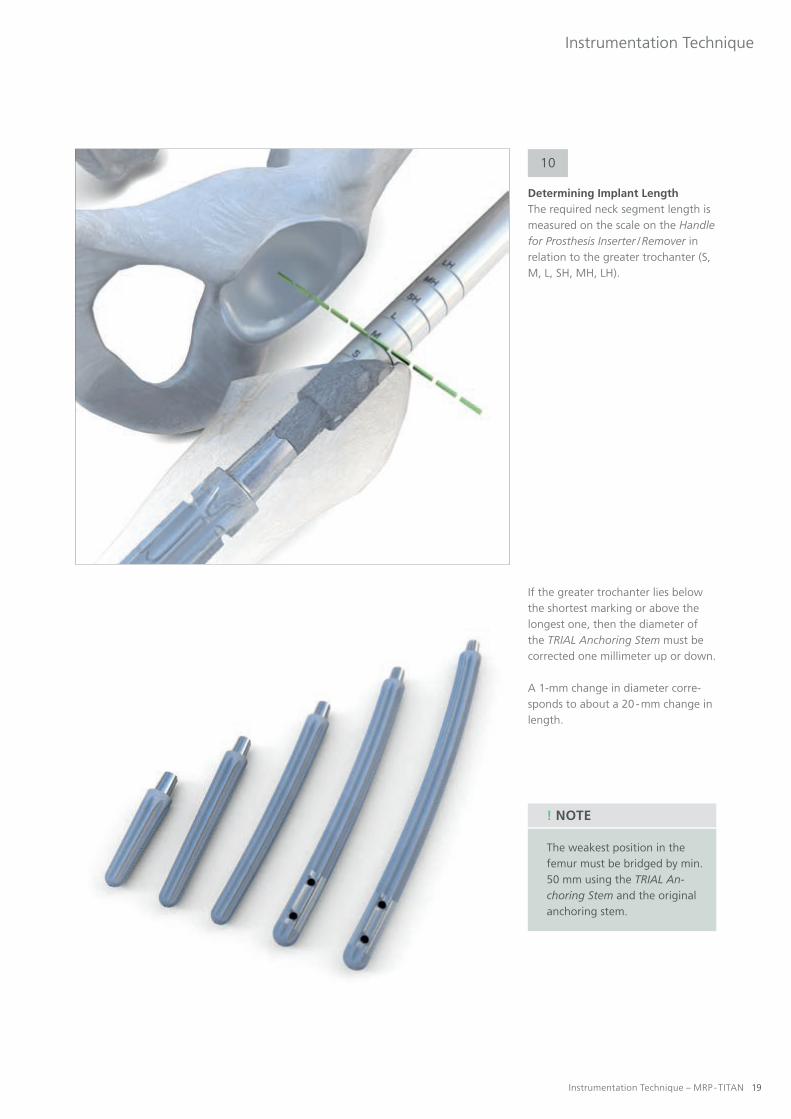
Determining Implant LengthThe required neck segment length is measured on the scale on the Handle for Prosthesis Inserter / Remover in relation to the greater trochanter (S, M, L, SH, MH, LH).
If the greater trochanter lies below the shortest marking or above the longest one, then the diameter of the TRIAL Anchoring Stem must be corrected one millimeter up or down.
A 1-mm change in diameter corre-sponds to about a 20 - mm change in length.
The weakest position in the femur must be bridged by min. 50 mm using the TRIAL An-choring Stem and the original anchoring stem.
! NOTE

20 Instrumentation Technique – MRP - TITAN
Instrumentation Technique
Trial Assembly
11
Placing the neck segmentAfter the TRIAL Anchoring Stem has been impacted, the Knurled Screw Sis unscrewed and the Handle for Prosthesis Inserter / Remover is removed.
Using the Cutter for Neck Prosthesis inserted over the Guide Rod which remains in place in the TRIAL An-choring Stem, the surgeon manually creates space for the TRIAL Prosthesis Neck.

Instrumentation Technique – MRP - TITAN 21
Instrumentation Technique
The Cutter for Prosthesis Neck may only be operated manual-ly. It must not be connected to a machine.
! NOTE
The scale on the Guide Rod also shows whether the Cutter for Prosthesis Neck has reached its final position.
The markings on the Guide Rod are shown here in color for greater cla-rity. The actual Guide Rod does not have any color coding.

22 Instrumentation Technique – MRP - TITAN
Instrumentation Technique
Trial Assembly
Remove the Setting Instrument for the Prosthesis and the Guide Rod. Then a trial reduction is performed using the TRIAL Ball. Correct leg length, soft-tissue tension, and func-tion are verified.
After the taper surface on the end of the stem has been cleaned, the Set-ting Instrument for the Prosthesis for the selected TRIAL Prosthesis Neck is definitively inserted over the Guide Rod. The TRIAL Prosthesis Neck can be fixed in the desired anteversion by tapping it lightly with a hammer. If an extension sleeve is also required, then the TRIAL Prosthesis Neckand the TRIAL Extension Sleeve are first assembled by pressing them tightly together before they are seated.
Connecting the TRIAL Prosthesis Neck to the Setting Instrument for the Prosthesis.

Instrumentation Technique – MRP - TITAN 23
Instrumentation Technique
12
Disconnecting the Trial AssemblyThe impression instrument facilitates controlled release of the individual components TRIAL Anchoring Stem, TRIAL Extension Sleeve, and TRIAL Prosthesis Neck.
Three situations are distinguished:
TRIAL Prosthesis Neck and TRIAL Extension Sleeve TRIAL Extension Sleeve and TRIAL Anchoring Stem TRIAL Prosthesis Neck and TRIAL Anchoring Stem
If the TRIAL Prosthesis Neck is to be separated from the TRIAL Extension Sleeve (), then you must use the Impression Threaded Rod for Impres-sion Instrument (separating rod with threading).
The Impression Rod for Impression Instrument is screwed into the TRIAL Prosthesis Neck with the Socket Wrench SW 3,5. The assembled impression instrument is slid over the rod and screwed into the TRIAL Prosthesis Neck.
Then the components are separa-ted from each other by turning the Spindle for the impression instru-ment.
Bone fracture due to failure to use
the Counter Holder:
• Danger of injury caused by implant loosening! Always use the Counter Holder when removing the screw, working with the impression instrument, the Torque Limiter and the Torsionfree Preloading Instrument (TOV) to prevent rotation forces from being trans- fered to the bone.
WARNING
24 Instrumentation Technique – MRP - TITAN
Instrumentation Technique
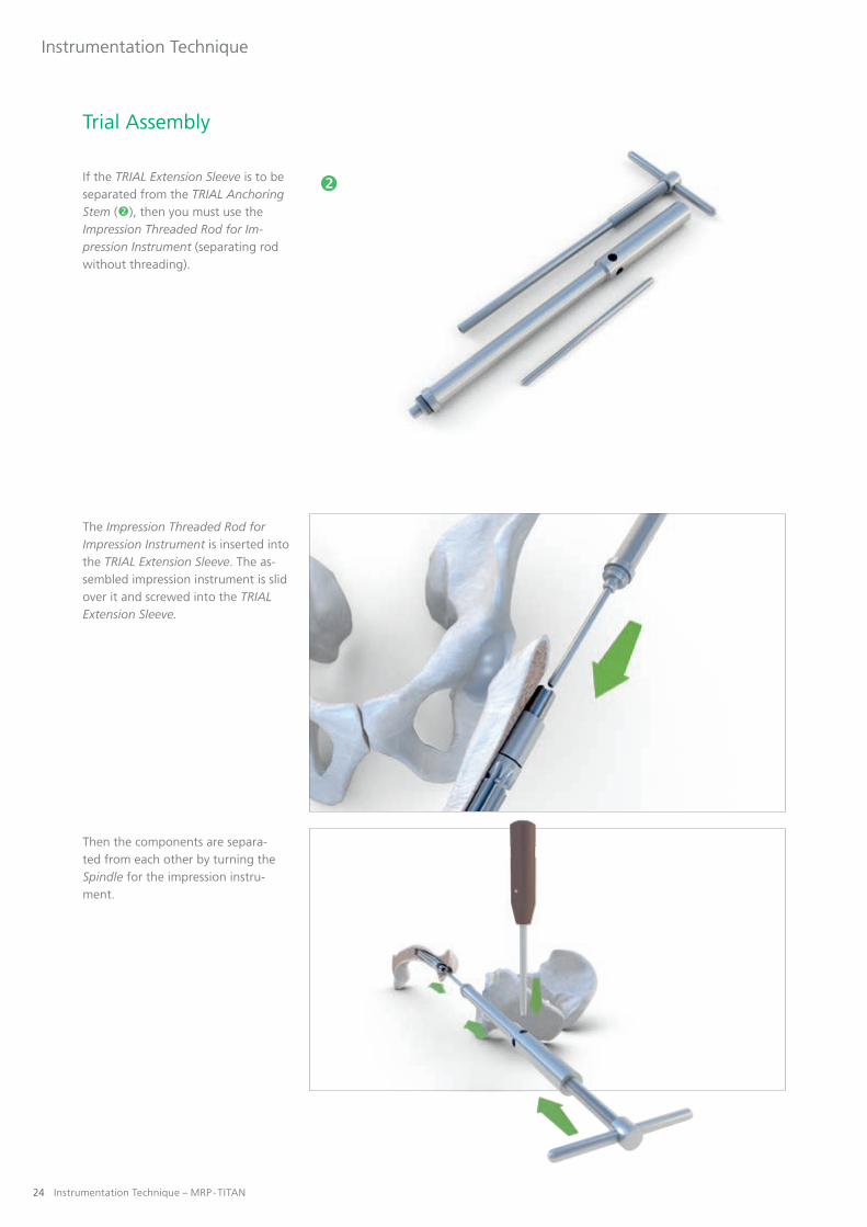
If the TRIAL Extension Sleeve is to be separated from the TRIAL Anchoring Stem (), then you must use the Impression Threaded Rod for Im-pression Instrument (separating rod without threading).
The Impression Threaded Rod for Impression Instrument is inserted into the TRIAL Extension Sleeve. The as-sembled impression instrument is slid over it and screwed into the TRIAL Extension Sleeve.
Then the components are separa-ted from each other by turning the Spindle for the impression instru-ment.
Trial Assembly

Instrumentation Technique – MRP - TITAN 25
Instrumentation Technique
If the TRIAL Prosthesis Neck is to be separated from the TRIAL Anchoring Stem (), then you must use the Impression Threaded Rod for Im-pression Instrument (separating rod without threading).
After the Impression Threaded Rod for Impression Instrument has been inserted into the TRIAL Prosthesis Neck, the assembled impression instrument is inserted over the Im-pression Threaded Rod for Impressi-on Instrument and screwed into the TRIAL Prosthesis Neck.
Then the components are separa-ted from each other by turning the Spindle for the impression instru-ment.

26 Instrumentation Technique – MRP - TITAN
Instrumentation Technique
Trial Assembly
Removing the TRIAL Anchoring StemIn order to place the definitive implant, the entire TRIAL Anchoring Stem must be removed. One can either extract the entire system or di-sassemble the prosthesis and remove each of the components separately.
Different Knurled Screws will be required depending on the specific implant configuration.
Removal of the TRIAL Anchoring Stem
Knurled Screw S
Removal of the TRIAL Anchoring Stemand TRIAL Prosthesis Neck
Or:TRIAL Anchoring Stem and
TRIAL Extension Sleeve
Knurled Screw M and Sliding Disk
Removal of the TRIAL Anchoring Stem and TRIAL Prosthesis Neck and
TRIAL Extension Sleeve
Knurled Screw L and Sliding Disk
To secure the connection, proceed as follows: Screw in the Knurled Screw (S, M, L) as far as it will go. Then insert the Socket Wrench SW 3,5 at a right angle and give it an additio-nal half turn clockwise to secure the construct.
If the trial assembly is to be removed from the site in pieces, then the indi-vidual components must be separa-ted (see item 12).
13

Instrumentation Technique – MRP - TITAN 27
Instrumentation Technique
Placing the Definitive Implant
Placing the anchoring stem The definitive anchoring stem is placed in the same manner as the TRIAL Anchoring Stem. The first step is to screw the Guide Rod all the way into the anchoring stem. The Handle for Prosthesis Inserter / Remover is slid over it and the Knurled Screw S is screwed tight. Then insert the Socket Wrench SW 3,5 at a right angle and give the Knurled Screw S an additio-nal half turn clockwise to secure the construct.
14
Then the anchoring stem is impacted. The goal is to place the anchoring stem in exactly the same position as the TRIAL Anchoring Stem. If this is not the case, you have the option of performing another trial reduction with the TRIAL Prosthesis Neck to de-termine the optimum neck segment length. If the definitive anchoring stem has been placed deeper, then space must again be created for the new neck segment using the Cutter for Prosthesis Neck inserted over the Guide Rod, which remains in place in the anchoring stem.
Then the Knurled Screw S and the Handle for Prosthesis Inserter / Remover are removed.

28 Instrumentation Technique – MRP - TITAN
Instrumentation Technique
Placing the Definitive Implant
Placing the Definitive ImplantAfter the taper surface has been cleaned, the neck segment can be inserted over the Guide Rod with the aid of the Setting Instrument for the Prosthesis.
The neck segment can be fixed in the desired anteversion by tapping it lightly with a hammer. If required, an extension sleeve can be placed separately or in combination with the implant neck.
Once the Setting Instrument for the Prosthesis and the Guide Rod have been removed, a trial reduction can again be performed with the TRIAL Balls S, M, or L. Correct leg length, soft-tissue tension, and function of the prosthesis are then verified before the prosthesis is pretensioned to a defined torque.
Foreign matter (e.g. cement remains,
tissue, bone) between the implant
components:
• Danger of injury caused by implant failure! Clean the implant components thoroughly.
Damage to the cone connection:
• Risk of implant failure! Ensure careful implantation. Do not use damaged implants.
WARNING
WARNING

Instrumentation Technique – MRP - TITAN 29
Instrumentation Technique
Pretensioning the Definitive ImplantThe Torsionfree Preloading Instru-ment (TOV) is used to achieve de-fined pretensioning of the definitive implants assembled in situ.
15

30 Instrumentation Technique – MRP - TITAN
Instrumentation Technique
Placing the Definitive Implant
The following rule should be obser-ved when using the Knurled Screw for pretensioning:
Anchoring stem and neck segmentOr:
Anchoring stem and extension sleeve
Knurled Screw M
Anchoring stem, neck segment, and extension sleeve
Knurled Screw L
For definitive pretensioning, the Handle for Prosthesis Inserter / Remo-ver is slid over the Guide Rod (which is screwed in as far as it will go) and secured with the appropriate Knurled Screw for torsion-free preloading.
Instrumentation Technique – MRP - TITAN 31
Instrumentation Technique
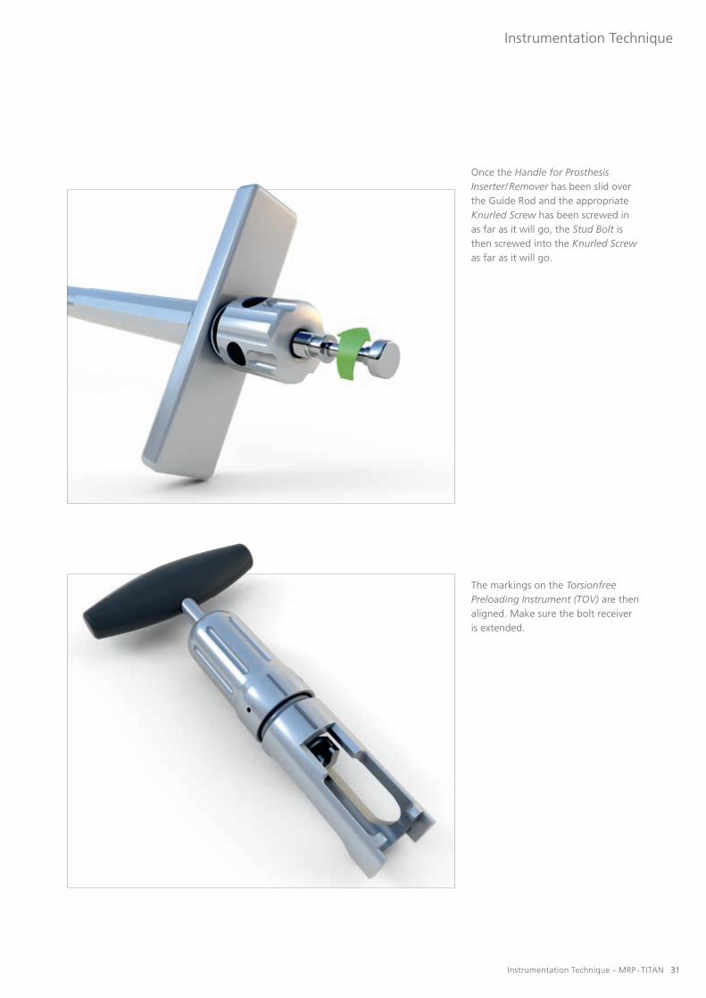
Once the Handle for Prosthesis Inserter/ Remover has been slid over the Guide Rod and the appropriate Knurled Screw has been screwed in as far as it will go, the Stud Bolt is then screwed into the Knurled Screw as far as it will go.
The markings on the Torsionfree Preloading Instrument (TOV) are then aligned. Make sure the bolt receiver is extended.

32 Instrumentation Technique – MRP - TITAN
Instrumentation Technique
Placing the Definitive Implant
Pull the Torsionfree Preloading Instrument (TOV) slightly until it is firmly in place on the Handle for Prosthesis Inserter / Remover.
Place the Torsionfree Preloading Instrument (TOV) on the Handle for Prosthesis Inserter / Remover and push it sideways over the Knurled Screw and Stud Bolt.
Make sure that the instrument and Stud Bolt engage properly.
! NOTE
Aborted pre-tensioning procedure
of the implant components using
the TOV: • Risk of implant failure due to insufficiently tensioned compo- nents! Always use new Stud Bolt even if it had not been destroyed during the first aborted attempt.In case of a prematurely aborted tensioning attempt, dispose of the Stud Bolt.
WARNING

Instrumentation Technique – MRP - TITAN 33
Instrumentation Technique
Although the use of the Torsion-free Preloading Instrument (TOV) minimizes torsion forces, the Counter Holder must always be attached to the Handle for Prosthesis Inserter / Remover or the prosthesis.
The Counter Holder can be used in three different ways depending on how the patient is positioned (see illustrations).

34 Instrumentation Technique – MRP - TITAN
Instrumentation Technique
Turn the handle of the Torsionfree Preloading Instrument (TOV) clock-wise until the Stud Bolt is cut apart. Then the components are locked together and pretensioned.
As long as the Stud Bolt has not been divided, the handle of the TOV instrument springs back.
! NOTE
Placing the Definitive Implant

Instrumentation Technique – MRP - TITAN 35
Instrumentation Technique
Then the Torsionfree Preloading Instrument (TOV) is removed from the Knurled Screw or the Handle for Prosthesis Inserter / Remover, respectively.
The rest of the Stud Bolt re-mains in the instrument until it has been turned counterclock-wise to the original position.
! NOTE

�
36 Instrumentation Technique – MRP - TITAN
Instrumentation Technique
After the instruments have been removed, the screw M6 is screwed into the neck segment with the Allen Key SW 5 Ball Head 300 mm to lock it.
Anchoring stem and neck segment = screw M6 (short)
Anchoring stem, neck segment, and extension sleeve = screw M6 (long)
Components for inserting and tightening the M6 locking screw:
Tommy Bar for Socket Head Wrench SW 6 Torque Limiter 25±1 Nm Allen Key SW 5 Ball Head 300 mm Allen Key SW 5 � Screw M6 (short) Screw M6 (long)
In order to set the screw M6 use the Allen Key SW 5 Ball Head 300 mm, since it tole-rates slight angle deviations during insertion. The screw M6 centers itself in the thread.
! NOTE
Placing the Definitive Implant
Instrumentation Technique – MRP - TITAN 37
Instrumentation Technique
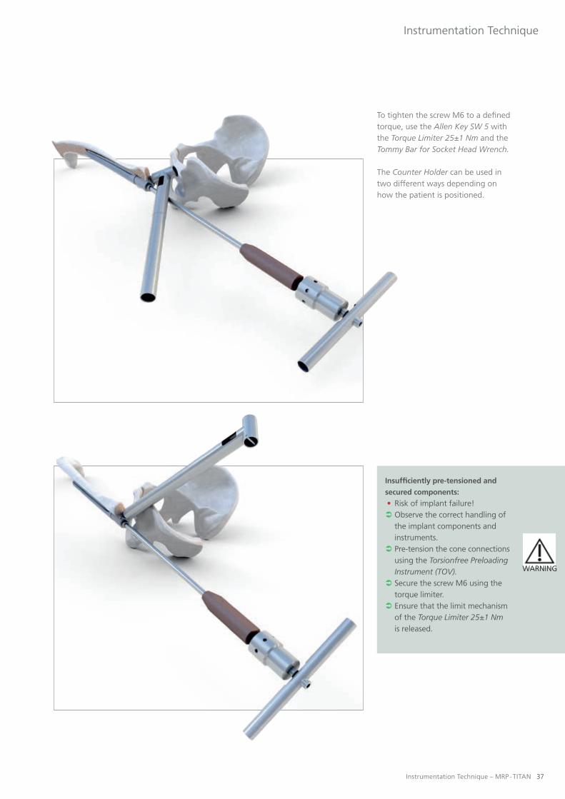
To tighten the screw M6 to a defined torque, use the Allen Key SW 5 with the Torque Limiter 25±1 Nm and the Tommy Bar for Socket Head Wrench.
The Counter Holder can be used in two different ways depending on how the patient is positioned.
Insufficiently pre-tensioned and
secured components:
• Risk of implant failure! Observe the correct handling of the implant components and instruments. Pre-tension the cone connections using the Torsionfree Preloading Instrument (TOV). Secure the screw M6 using the torque limiter. Ensure that the limit mechanism of the Torque Limiter 25±1 Nm is released.
WARNING

38 Instrumentation Technique – MRP - TITAN
Instrumentation Technique
Sealing the neck segmentAfter the screw M6 has been placed, the final step is to insert the sealing screw into the neck segment and hand tighten it. The screw has no mechanical function. It only prevents ingrowth of soft tissue and bone into the neck segment.
Securing the Prosthetic TrochanterIf the neck segment for trochanter has been used, then the last step is to place the prosthetic greater tro-chanter in the desired position.
To permanently secure the desired alignment, the sealing screw must be placed with the Torque Limiter 25±1 Nm.
16
17
Placing the Definitive Implant

Instrumentation Technique – MRP - TITAN 39
Instrumentation Technique
Placing the Definitive Femoral BallThe taper is carefully cleaned and the selected femoral ball is attached and rotated to fix it in place. The connec-tion is then locked by lightly tapping the construct with a plastic mallet.
18
Ensure that the inner cone of the ball head corresponds to the outer cone of the anchoring stem. Ensure that the outer diameter of the ball head corresponds to the inner diameter of the inlay for acetabular treatment.
Combination of implant components of differing sizes:
• Damage to implant components! Only use components of the same size.
Ball neck lengths approved by PETER BREHM GmbH for Steckkugeln manufactured by PETER BREHM GmbH made of the materials BIOLOX forte, BIOLOX delta, BIOLOX Option, Titan and CoCr are: S (-4), M (0), L (+4)
Use of damaged or defective implants / instruments:
• Danger of injury caused by premature implant breakage! Do not use instruments/implants with recognizable damage.
Damage to the cone connection:
• Risk of implant failure! Ensure careful implantation. Do not use damaged implants.
In the case of combination with other components of PETER BREHM GmbH, observe the instructions in the respective instructions for use, instrumentation instruc- tions and, if necessary, the surgery videos. In case of any questions or uncertainties, contact PETER BREHM GmbH.
When combining ball heads made of CoCr or TiAl6V4 (TiN
coating) with sliding surfaces made of ceramic or metal:
• Danger of injury caused by implant failure! Do not combine implant components with sliding surfaces made of ceramic or metal. Combine ball heads made of CoCr and Ti6Al4V only with PE inlays.
Combination with oversized ball heads:
• Danger of injury caused by implant breakage! • Impairment of the component reliability due to increased leverage forces!
PETER BREHM GmbH does not guarantee component reliability for the combination of ball head sizes L1-L4 with hip implants because the leverage forces are increased thereby.
WARNING
WARNING
WARNING
WARNING
WARNING

40 Instrumentation Technique – MRP - TITAN
Instrumentation Technique
Postoperative Disassembly
Releasing the Pretensioned Com-ponents and Disassembling the ImplantThe sealing screw and the screw M6 are unscrewed and removed with the Allen Key SW 5 and the Tommy Bar for Socket Head Wrench SW 6. Then the implant can be disassem-bled with the aid of the impression instrument.
19
First remove the sealing screw M14x1 and the screw M6. To do so, use the Counter Holder and the Allen Key SW 5.
! NOTE

�
�
Instrumentation Technique – MRP - TITAN 41
Instrumentation Technique
Components of the revision separa-ting instrumentation:
Impression Rod Threaded Impression Rod Revision Impression Rod with Nip Spindle� Adapter Revision Impression Instrument (Revision)� Tommy Bar for Socket Head Wrench SW 6
The degree of activity or body weight of the patient may cause additional settling of the component, which can hamper the separation of the implant.
PETER BREHM GmbH can provide an additionally reinforced impression instrument for subsequent revision of the endo-prosthesis.
! NOTE

42 Instrumentation Technique – MRP - TITAN
Instrumentation Technique
Postoperative Disassembly
Three situations are distinguished when disassembling the prosthesis:
Separation of neck segment and anchoring stem
Screw in the Impression Rod and insert the assembled impression instrument (Impression Instrument (Revision), Spindle, and Tommy Bar for Socket Head Wrench SW 6) over the rod and screw the separating instrument into the neck segment.
Separation of neck segment and extension sleeve
Screw the Threaded Impression Rod Revision into the extension sleeve and insert the assembled impression instrument (Impression Instrument (Revision), Spindle, and Tommy Bar for Socket Head Wrench SW 6) over the rod and screw the separating instrument into the neck segment.
Bone fracture due to failure to use
the Counter Holder:
• Danger of injury caused by im- plant loosening! Always use the Counter Holder when removing the screw, wor- king with the impression instru- ment, the Torque Limiter and the Torsionfree Preloading Instrument (TOV) to prevent rotation forces from being transferred to the bone.
WARNING

Instrumentation Technique – MRP - TITAN 43
Instrumentation Technique
Separation of extension sleeve and anchoring stem
Screw the Impression Rod with Nip into the anchoring stem and insert the assembled impression instrument (Impression Instrument (Revision), Spindle, Adapter Revision, Tommy Bar for Socket Head Wrench SW 6) over the rod and screw the im-pression instrument into the neck segment.
Then the components are separa-ted from each other by turning the Spindle with the Tommy Bar for Socket Head Wrench SW 6.
First remove the sealing screw M14x1 and the screw M6. To do so, use the Counter Holder and the Allen Key SW 5 (see p. 40).
If the cone connections are extremely fixed, using a metal hammer to impact the Spindle repeatedly is advisable. These impulses cause loosening.
! NOTE

44 Instrumentation Technique – MRP - TITAN
Instrumentation Technique
Removing the Definitive Implant
20
RemovalThree situations are distinguished when removing the prosthesis: For all three situations you will need the Guide Rod, the Handle for Prosthe-sis Inserter / Remover and a Knurled Screw to secure the construct. Note that the Guide Rod must be screwed all the way into the prosthesis. Then the Handle for Prosthesis Inserter / Remover is slid over the Guide Rod and secured with a Knurled Screw. To secure the connection, proceed as follows: Screw in the Knurled Screw as far as it will go. Then insert the Socket Wrench SW 3,5 at a right an-gle and give it an additional half turn clockwise to secure the construct.
The length of the Knurled Screw de-pends on the number of components to be removed.
�
Components for removing the definitive implant:
Handle for Prosthesis Inserter / Remover Guide Rod Knurled Screw S Knurled Screw M and Sliding Disk � Knurled Screw L and Sliding Disk

Instrumentation Technique – MRP - TITAN 45
Instrumentation Technique
The length of the Knurled Screw de-pends on the number of components to be removed.
Anchoring stem
Knurled Screw S
Anchoring stem and neck segment
Or:Anchoring stem and
extension sleeve
Knurled Screw M and Sliding Disk
Anchoring stem, extension sleeve, and neck segment
Knurled Screw L and Sliding Disk

46 Instrumentation Technique – MRP - TITAN
Supplementary Surgical Technique
Removing the Definitive Implant
Then the components can be extracted by tapping them with a hammer.
Removing the Entire System with the Slap HammerAlternatively, the implant can be removed with the Slap Hammer. One can either extract the entire implant system or remove each of the com-ponents separately.
The Slap Hammer must be ordered separately as it is not included in the standard instrumentation set.
First remove the sealing screw M14x1 and the screw M6. To do so, use the Counter Holder and the Allen Key SW 5 (see p. 40).
! NOTE
21
Components for removing the defini-tive implant with the Slap Hammer:
Slap Hammer Adapter M14x1 Bolts Threaded Rod (M6)

Instrumentation Technique – MRP - TITAN 47
Supplementary Surgical Technique
Before the Slap Hammer can be con-nected, the Adapter M14x1 must be screwed into the neck segment.
Then the Adapter M14x1 and Slap Hammer are connected with the Bolt.
48 Instrumentation Technique – MRP - TITAN
Supplementary Surgical Technique
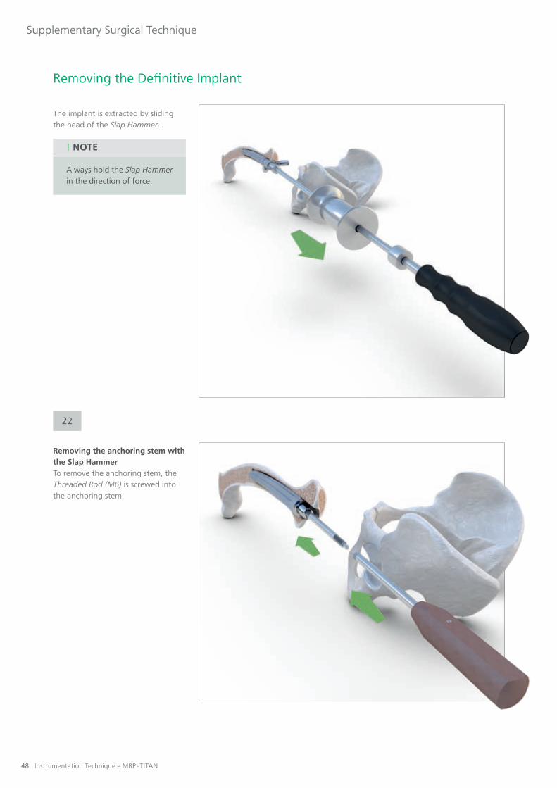
The implant is extracted by sliding the head of the Slap Hammer.
Always hold the Slap Hammer in the direction of force.
! NOTE
Removing the anchoring stem with the Slap HammerTo remove the anchoring stem, the Threaded Rod (M6) is screwed into the anchoring stem.
Removing the Definitive Implant
22

Instrumentation Technique – MRP - TITAN 49
Supplementary Surgical Technique
The Threaded Rod (M6) is mounted on the Adapter M14x1.
Then the Slap Hammer is connected to the Adapter M14x1 and the anchoring stem is extracted.

MRP - TITANSUPPLEMENTARY PRODUCTS

Instrumentation Technique – MRP - TITAN 51
Supplementary Products
Impaction Grafting System (IGS)
Indications
I All proximal femoral defects where the cortex is intact, regardless of the stem diameter
Objectives and Tasks
I Biologic reconstruction of bony defectsI Achieving a positive-locking interference fit by filling the entire bone-implant interfaceI Creating an initial situation sufficient for sustainable bone remodeling and proximal stress transfer
Advantages of the System
I The guided mallet system eliminates the risk of damaging the implant

52 Instrumentation Technique – MRP - TITAN
Supplementary Products
MRP-TITAN mdV Aiming Device
Indications
I Can be used with all interlocking anchoring stems of the MRP-TITAN system
Objectives and Tasks
I Quick interlockingI Reliable interlocking
Advantages of the System
I This instrument can shorten the surgical procedure. It also minimizes the patient's exposure to ionizing radiation as the locking bolt can be placed without fluoroscopic control.

Instrumentation Technique – MRP - TITAN 53
Supplementary Products
MRP-TITAN pFE Proximal Femur Replacement
Indications
I Osteosarcomas and metastasesI Revision with extensive bone resectionI Bone loss due to traumaI Extensive loss of bone materialI Severe deformities as in osteomyelitis
Objectives and Tasks
I Modular anatomic design for functional reconstructionI Allows unrestricted resectionI Optimal kinematicsI Precise implantation with MRP-TITAN instrumentationI Allows fixation of soft tissue
Advantages of the System
I Cementless MRP-TITAN anchoring stems available in all lengths and diametersI All the advantages of the MRP-TITAN system still applyI Adapters and sleeves are extendable in 10 mm incrementsI Completely modular systemI Instrumentation identical to MRP-TITANI Optional MRP-TITAN pFE lateral plate for additional stabilization

54 Instrumentation Technique – MRP - TITAN
Supplementary Products
KAM-TITAN
Indications
I Posttraumatic findings that contraindicate implantation of a total kneeI Findings after removal of infected total knee arthro- plasty that are not conducive to revision total arthroplastyI Degenerative joint disease that requires immediate full weight bearing I Loss of or damage to the knee extensorsI Neuromuscular indication
Advantages of the System
I Anatomic design with left and right variants (6° valgus, 7° flexion)I Cementless implantation (optional: cemented anchoring stems)I Freely selectable leg length and continuously adjustable external rotation in situI Intraoperative flexibility in any situationI Assembly with trial implants in situI Modules coupled in flexion (from 35°)I Escape route at every step of the procedureI Best results in long-term studies with a high degree of patient satisfactionI Can be used without restriction where bony ingrowth is absent or unlikely

Instrumentation Technique – MRP - TITAN 55
Supplementary Products
MRS-TITAN and MRS-TITAN Comfort
Indications
I Congenital or acquired hip joint defectsI Arthrosis (degenerative, rheumatic)I Joint replacement (revision) already carried out and worn or in case of failed surgeryI Defect of the geometric rotation centerI Defects or malfunctions of the hip jointI Post-traumatic arthritisI Severe deformities (e.g. osteomyelitis)
Advantages of the System
I Immediate stable fixation in healthy boneI The mechanical stability of the implant minimizes motion, ensuring a situation conducive to remodeling of the bone graftI Restoration of the physiologic geometric center of rotation improves the biomechanics of the hipI The reduction in inventory and the elimination of costly preoperative imaging studies reduce costsI Maximum flexibility for adjusting inclination and anteversion
MRS-TITAN
MRS-TITAN Comfort

pb
-mrp
-op
-LLB
L609
-51-
2014
0424
-EN
G-f
d
PETER BREHM GmbHAm Mühlberg 30
91085 Weisendorf, GermanyTelephone + 49 9135 -71 03 -0Facsimile + 49 9135 -71 03 -16
www.peter-brehm.de
This brochure is intended for physicians only and is not suitable as a source of information for lay per-sons. The information about the products and/or procedures described in this brochure is of a general nature and does not represent the advice or recommendation of a physician. The information provided here does not in any way represent an opinion on the diagnosis or treatment of any specific medical case. The respective patient must be examined individually and advised accordingly. This brochure can neither completely nor partially substitute these measures.
The information contained in this brochure has been produced and compiled by medical experts and qualified PETER BREHM employees to the best of their knowledge. The greatest possible care has been taken to ensure that the information provided is correct and comprehensible.
! NOTE