mr-c 56 mr-e 60 mr-j2-jr 73 mr-j2-super 200~230 vac 76 mr ...€¦ · mitsubishi electric...
TRANSCRIPT
Mitsubishi Electric Automation | Servomotors and Amplifiers 55
Servomotors and Amplifiers
MR-C 56
MR-E 60
MR-J2-JR 73
MR-J2-Super 200~230 VAC 76
MR-J2-Super 380~480 VAC 95
MR-J3 115
Sold
by
AA
Ele
ctric
1-8
00-2
37-8
274
Lake
land
, FL
• Law
renc
evill
e, G
A •
Gre
ensb
oro,
NC
• Ea
st R
uthe
rfor
d, N
J w
ww
.A-A
elec
tric
.com
56
nS
ER
VO
MO
TO
RS
AN
D A
MP
LIF
IER
S
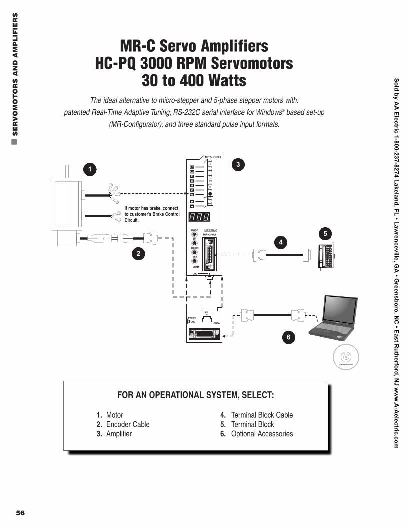
FOR AN OPERATIONAL SYSTEM, SELECT:
1. Motor 4. Terminal Block Cable2. Encoder Cable 5. Terminal Block3. Amplifier 6. Optional Accessories
If motor has brake, connectto customer’s Brake ControlCircuit.
MR-C Servo AmplifiersHC-PQ 3000 RPM Servomotors
30 to 400 WattsThe ideal alternative to micro-stepper and 5-phase stepper motors with:
patented Real-Time Adaptive Tuning; RS-232C serial interface for Windows® based set-up
(MR-Configurator); and three standard pulse input formats.
Sold by AA
Electric 1-800-237-8274 Lakeland, FL • Lawrenceville, G
A • G
reensboro, NC
• East Rutherford, N
J ww
w.A
-Aelectric.com
Mitsubishi Electric Automation | Servomotors and Amplifiers 57
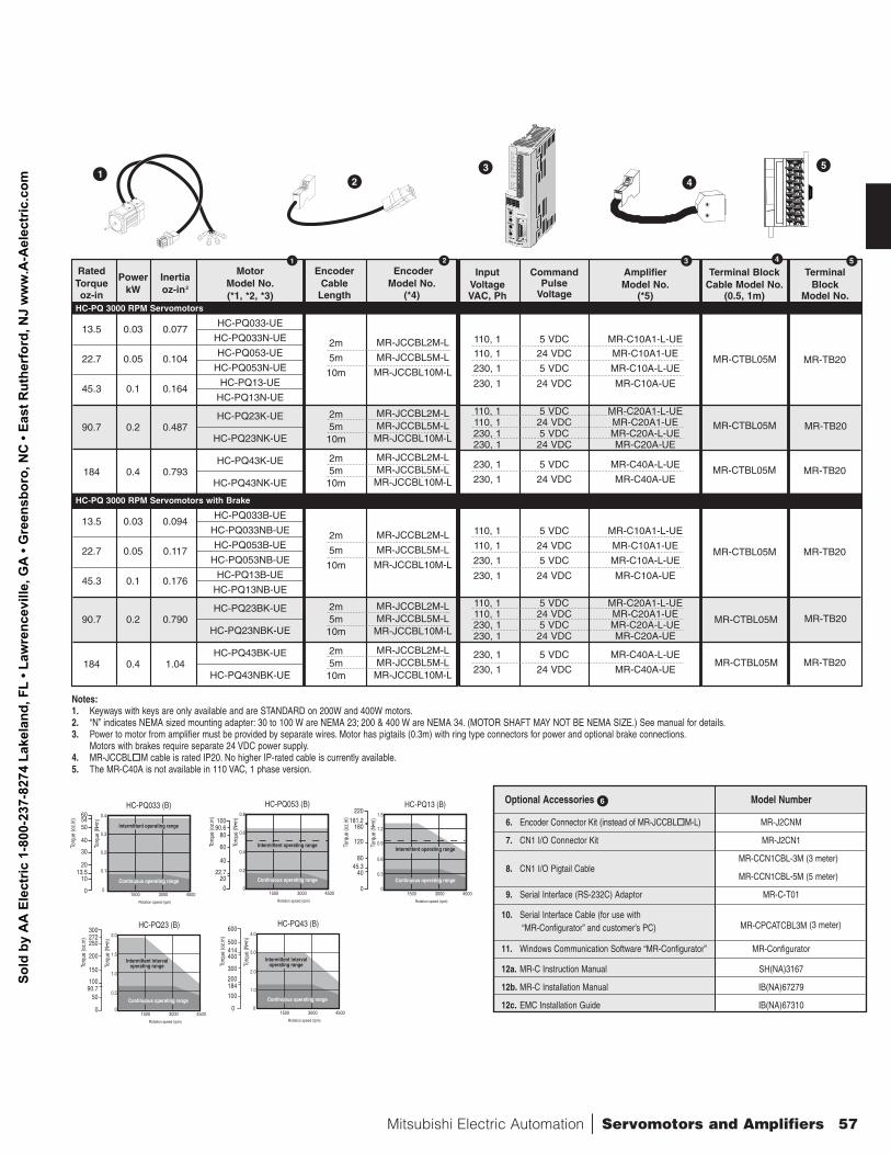
Notes:1. Keyways with keys are only available and are STANDARD on 200W and 400W motors.2. “N” indicates NEMA sized mounting adapter: 30 to 100 W are NEMA 23; 200 & 400 W are NEMA 34. (MOTOR SHAFT MAY NOT BE NEMA SIZE.) See manual for details.3. Power to motor from amplifier must be provided by separate wires. Motor has pigtails (0.3m) with ring type connectors for power and optional brake connections.
Motors with brakes require separate 24 VDC power supply.4. MR-JCCBLoM cable is rated IP20. No higher IP-rated cable is currently available.5. The MR-C40A is not available in 110 VAC, 1 phase version.
5
4
3
Input Command Amplifier Terminal Block TerminalVoltage Pulse Model No. Cable Model No. BlockVAC, Ph Voltage (*5) (0.5, 1m) Model No.
110, 1 5 VDC MR-C10A1-L-UE110, 1 24 VDC MR-C10A1-UE
230, 1 5 VDC MR-C10A-L-UE
230, 1 24 VDC MR-C10A-UE
110, 1 5 VDC MR-C20A1-L-UE110, 1 24 VDC MR-C20A1-UE230, 1 5 VDC MR-C20A-L-UE230, 1 24 VDC MR-C20A-UE
230, 1 5 VDC MR-C40A-L-UE
230, 1 24 VDC MR-C40A-UE
110, 1 5 VDC MR-C10A1-L-UE
110, 1 24 VDC MR-C10A1-UE
230, 1 5 VDC MR-C10A-L-UE
230, 1 24 VDC MR-C10A-UE
110, 1 5 VDC MR-C20A1-L-UE110, 1 24 VDC MR-C20A1-UE230, 1 5 VDC MR-C20A-L-UE230, 1 24 VDC MR-C20A-UE
230, 1 5 VDC MR-C40A-L-UE
230, 1 24 VDC MR-C40A-UE
3 4 5
21
MR-CTBL05M MR-TB20
MR-CTBL05M MR-TB20
MR-CTBL05M MR-TB20
MR-CTBL05M MR-TB20
MR-CTBL05M MR-TB20
MR-CTBL05M MR-TB20
RatedPower Inertia
Motor Encoder EncoderTorque
kW oz-in2 Model No. Cable Model No.oz-in (*1, *2, *3) Length (*4)
HC-PQ 3000 RPM Servomotors
HC-PQ033-UE13.5 0.03 0.077
HC-PQ033N-UE
HC-PQ053-UE22.7 0.05 0.104
HC-PQ053N-UE
HC-PQ13-UE45.3 0.1 0.164
HC-PQ13N-UE
HC-PQ23K-UE90.7 0.2 0.487
HC-PQ23NK-UE
HC-PQ43K-UE184 0.4 0.793
HC-PQ43NK-UE
HC-PQ 3000 RPM Servomotors with Brake
HC-PQ033B-UE13.5 0.03 0.094
HC-PQ033NB-UE
HC-PQ053B-UE22.7 0.05 0.117
HC-PQ053NB-UE
HC-PQ13B-UE45.3 0.1 0.176
HC-PQ13NB-UE
HC-PQ23BK-UE90.7 0.2 0.790
HC-PQ23NBK-UE
HC-PQ43BK-UE184 0.4 1.04
HC-PQ43NBK-UE
1
2m
5m
10m
MR-JCCBL2M-L
MR-JCCBL5M-L
MR-JCCBL10M-L
2m5m10m
MR-JCCBL2M-LMR-JCCBL5M-LMR-JCCBL10M-L
2m5m10m
MR-JCCBL2M-LMR-JCCBL5M-LMR-JCCBL10M-L
2m
5m
10m
MR-JCCBL2M-L
MR-JCCBL5M-L
MR-JCCBL10M-L
2m5m10m
MR-JCCBL2M-LMR-JCCBL5M-LMR-JCCBL10M-L
2m5m10m
MR-JCCBL2M-LMR-JCCBL5M-LMR-JCCBL10M-L
2
Optional Accessories Model Number
6. Encoder Connector Kit (instead of MR-JCCBLoM-L) MR-J2CNM
7. CN1 I/O Connector Kit MR-J2CN1
8. CN1 I/O Pigtail CableMR-CCN1CBL-3M (3 meter)
MR-CCN1CBL-5M (5 meter)
9. Serial Interface (RS-232C) Adaptor MR-C-T01
10. Serial Interface Cable (for use with“MR-Configurator” and customer’s PC) MR-CPCATCBL3M (3 meter)
11. Windows Communication Software “MR-Configurator” MR-Configurator
12a. MR-C Instruction Manual SH(NA)3167
12b. MR-C Installation Manual IB(NA)67279
12c. EMC Installation Guide IB(NA)67310
HC-PQ033 (B)
1500 3000 4500
Rotation speed (rpm)
Torq
ue (o
z.in
) 60
50
Torq
ue (N
•m)
40
30
20
10
0
0.4
0.3
0.2
0.1
0
Continuous operating range
Intermittent operating range
HC-PQ053 (B)
1500 3000 4500
Rotation speed (rpm)
Torq
ue (o
z.in
)
100
Torq
ue (N
•m)
0.8
0.6
0.4
0.2
0
Continuous operating range
80
60
40
200
HC-PQ23 (B)
1500 3000 4500
Rotation speed (rpm)
Torq
ue (o
z.in
)
300
250
Torq
ue (N
•m)
200
150
50
0
2.0
1.5
1.0
0.5
0
Continuous operating range
Intermittent intervaloperating range
HC-PQ13 (B)
1500 3000 4500
Rotation speed (rpm)
Torq
ue (o
z.in
)
220
Torq
ue (N
•m)
1.5
1.2
0.9
0.3
0
Continuous operating range
180
120
80
40
0
Intermittent operating range
HC-PQ43 (B)
1500 3000 4500
Rotation speed (rpm)
Torq
ue (o
z.in
)
600
500
Torq
ue (N
•m)
400
300
200
100
0
4.0
3.0
2.0
1.0
0
Continuous operating range
Intermittent intervaloperating rangeIntermittent operating range
54
13.5
90.6
22.7
0.6
181.2
45.3
272
10090.7
414
184
HC-PQ23 (B)
1500 3000 4500
Rotation speed (rpm)
Torq
ue (o
z.in
)
300
250
Torq
ue (N
•m)
200
150
50
0
2.0
1.5
1.0
0.5
0
Continuous operating range
Intermittent intervaloperating range
HC-PQ13 (B)
1500 3000 4500
Rotation speed (rpm)
Continuous operating range
Intermittent operating range
HC-PQ43 (B)
1500 3000 4500
Rotation speed (rpm)
Torq
ue (o
z.in
)
600
500
Torq
ue (N
•m)
400
300
200
100
0
4.0
3.0
2.0
1.0
0
Continuous operating range
Intermittent intervaloperating range
272
10090.7
414
184
HC-PQ 3000 RPM Servomotors with Brake
HC-PQ 3000 RPM Servomotors
6
Sold
by
AA
Ele
ctric
1-8
00-2
37-8
274
Lake
land
, FL
• Law
renc
evill
e, G
A •
Gre
ensb
oro,
NC
• Ea
st R
uthe
rfor
d, N
J w
ww
.A-A
elec
tric
.com
58
nS
ER
VO
MO
TO
RS
AN
D A
MP
LIF
IER
S
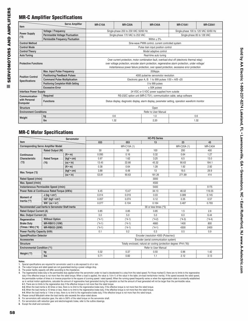
Servo Amplifier MR-C10A MR-C20A MR-C40A MR-C10A1 MR-C20A1Item
Power SupplyVoltage / Frequency Single-phase 200 to 230 VAC 50/60 Hz Single-phase 100 to 120 VAC 50/60 Hz
(*3)Permissible Voltage Fluctuation Single-phase 170 VAC to 253 VAC Single-phase 85 to 126 VACPermissible Frequency Fluctuation Within ± 5%
Control Method Sine-wave PWM control, current controlled systemControl Mode Pulse train input position controlControl Theory Model adaptive controlAuto Tuning Real-time auto tuning
Over current protection, motor combination fault, overload shut off (electronic thermal relay)Protective Functions over voltage protection, encoder alarm protection, regenerative alarm protection, under voltage/
instantaneous power failure protection, over speed protection, excessive error protection
Max. Input Pulse Frequency 200kpps
Position Control Positioning Feedback Pulses 4000 pulse/rev servomotor revolution
Specifications Command Pulse Multiplication Electronic gear A, B: 1 to 999 pulses 1/50 < A/B <20Positioning Completion Width Setting 0 to 999 pulsesExcessive Error ± 50K pulses
Interface Power Supply 24 VDC or 5 VDC power supplied from outside
Communication Required RS-232C option unit (MR-C-T01), communication cable, setup softwarewith Personal Functions Status display, diagnostic display, alarm display, parameter setting, operation waveform monitor
Computer
Structure OpenEnvironment Conditions Refer to User Manual
Weightkg 0.6 1.0 0.6
lbs 1.32 2.20 1.32
Servomotor HC-PQ SeriesItem 033 053 13 23 43Corresponding Servo Amplifier Model MR-C10A (1) MR-C20A (1) MR-C40A
Rated Output (W) 30 50 100 200 400
Continuous (N • m) 0.095 0.16 0.32 0.64 1.27Characteristic Rated Torque (kgf • cm) 0.97 1.62 3.25 6.5 13.0(*2) (*6) (oz • in) 13.45 22.66 45.32 90.63 184.1
(N • m) 0.38 0.64 1.28 1.92 2.92
Max. Torque (*2)(kgf • cm) 3.88 6.48 13 19.5 29.9(oz • in) 53.81 90.63 181.26 271.89 414
Rated Speed (r/min) 3000Max. Speed (r/min) 4500Instantaneous Permissible Speed (r/min) 5400 5175Power Rate at Continuous Rated Torque (kW/s) 6.45 13.47 34.13 46.02 116.55
J (kg • cm2) 0.014 0.019 0.03 0.089 0.145Moment of
GD2 (kgf • cm2) 0.057 0.074 0.12 0.35 0.57Inertia (*7)
WK2 (oz • in2) 0.077 0.104 0.164 0.487 0.793Recommended Load Inertia to Servomotor Shaft Inertia 30 or less times (*5)Rated Output Current (A) 0.85 0.85 0.85 1.5 2.8Max. Output Current (A) 5.0 5.0 5.0 6.0 6.44
Regenerative Without Option (*4-1) (*4-1) (*4-2) (*4-3) (*4-4)
Brake Duty MR-RB013 (10W) (*4-1) (*4-1) 4660 1400 800(Times / Min) (*4) MR-RB033 (30W) (*4-1) (*4-1) (*4-1) 4300 2400Power Facility Capacity (kVA) 0.1 0.2 0.3 0.5 0.9Speed/Position Detector Encoder (resolution 4000 (Pulse/rev))Accessories Encoder (serial communication system)Structure Totally enclosed, natural air cooling (protection degree: IP44 (*8))Environmental Condition (*1) Refer to User Manual
Weight (*7)kg 0.32 0.37 0.50 0.96 1.42lbs 0.71 0.82 1.1 2.12 3.13
MR-C Motor Specifications
MR-C Amplifier Specifications
Notes:1. Special specifications are required for servomotor used in a site exposed to oil or rain.2. The output torque and rated speed are not guaranteed during a power voltage drop.3. The power facility capacity will differ according to the impedance.4. The regenerative brake duty is the permissible duty applied when the servomotor under no load is decelerated to a stop from the rated speed. For those marked D, there are no limits to the regenerative
duty if the effective torque is not more than the rated torque. When a load is applied, the value is 1/(m+1) of the value in the table. (m=load inertia/motor inertia). If the speed exceeds the rated speed,the permissible number of times is in inverse proportion to the square of (running speed / rated speed). When the running speed frequently varies or when the regeneration state is constantly establishedas in vertical motion applications, calculate the amount of regenerative heat generated during the operation so that the amount of heat generated will not be larger than the permissible value.4-1. There are no limits to the regenerative duty if the effective torque is not more than the rated torque.4-2. When the load inertia is 30 times or less, there is no limit to the regenerative brake duty, if the effective torque is not more than the rated torque.4-3. When the load inertia is 10 times or less, there is no limit to the regenerative brake duty, if the effective torque is not more than the rated torque.4-4. When the load inertia is 1 time or less, there is no limit to the regenerative brake duty, if the effective torque is not more than the rated torque.
5. Please consult Mitsubishi when the load inertia ratio exceeds the value noted above.6. For servomotors with reduction gear, the ratio is 300% of the rated torque on the servomotor shaft.7. For servomotors with reduction gear and electromagnetic brake, refer to the outline drawings.8. Except the shaft and connector.
Sold by AA
Electric 1-800-237-8274 Lakeland, FL • Lawrenceville, G
A • G
reensboro, NC
• East Rutherford, N
J ww
w.A
-Aelectric.com
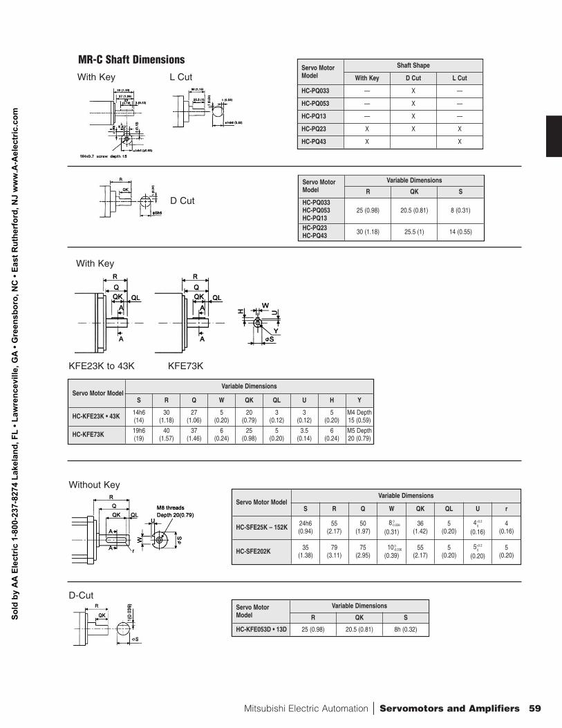
Mitsubishi Electric Automation | Servomotors and Amplifiers 59
Servo MotorModel
Shaft Shape
With Key D Cut L Cut
HC-PQ033 — X —
HC-PQ053 — X —
HC-PQ13 — X —
HC-PQ23 X X X
HC-PQ43 X X
Servo MotorModel
Variable Dimensions
R QK S
HC-PQ033HC-PQ053HC-PQ13
25 (0.98) 20.5 (0.81) 8 (0.31)
HC-PQ23HC-PQ43 30 (1.18) 25.5 (1) 14 (0.55)
MR-C Shaft DimensionsWith Key L Cut
D Cut
Servo MotorModel
Variable Dimensions
R QK S
HC-KFE053D • 13D 25 (0.98) 20.5 (0.81) 8h (0.32)
Servo Motor ModelVariable Dimensions
S R Q W QK QL U H Y
HC-KFE23K • 43K 14h6 (14)
30(1.18)
27(1.06)
5(0.20)
20(0.79)
3(0.12)
3(0.12)
5(0.20)
M4 Depth15 (0.59)
HC-KFE73K 19h6(19)
40(1.57)
37(1.46)
6(0.24)
25(0.98)
5(0.20)
3.5(0.14)
6(0.24)
M5 Depth20 (0.79)
Servo Motor ModelVariable Dimensions
S R Q W QK QL U r
HC-SFE25K – 152K 24h6 (0.94)
55(2.17)
50(1.97)
8 0-0.036
(0.31)36
(1.42)5
(0.20)4+0.2
0
(0.16)4
(0.16)
HC-SFE202K 35(1.38)
79(3.11)
75(2.95)
10 0-0.036
(0.39)55
(2.17)5
(0.20)5+0.2
0
(0.20)5
(0.20)
With Key
KFE23K to 43K KFE73K
Without Key
D-Cut
Sold
by
AA
Ele
ctric
1-8
00-2
37-8
274
Lake
land
, FL
• Law
renc
evill
e, G
A •
Gre
ensb
oro,
NC
• Ea
st R
uthe
rfor
d, N
J w
ww
.A-A
elec
tric
.com
60
nS
ER
VO
MO
TO
RS
AN
D A
MP
LIF
IER
S
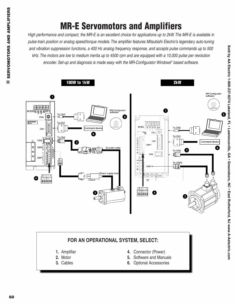
FOR AN OPERATIONAL SYSTEM, SELECT:
1. Amplifier 4. Connector (Power)2. Motor 5. Software and Manuals3. Cables 6. Optional Accessories
MR-E Servomotors and AmplifiersHigh performance and compact, the MR-E is an excellent choice for applications up to 2kW. The MR-E is available in
pulse-train position or analog speed/torque models. The amplifier features Mitsubishi Electric’s legendary auto-tuning
and vibration suppression functions, a 400 Hz analog frequency response, and accepts pulse commands up to 500
kHz. The motors are low to medium inertia up to 4500 rpm and are equipped with a 10,000 pulse per revolution
encoder. Set-up and diagnosis is made easy with the MR-Configurator Windows® based software.
Sold by AA
Electric 1-800-237-8274 Lakeland, FL • Lawrenceville, G
A • G
reensboro, NC
• East Rutherford, N
J ww
w.A
-Aelectric.com
Mitsubishi Electric Automation | Servomotors and Amplifiers 61
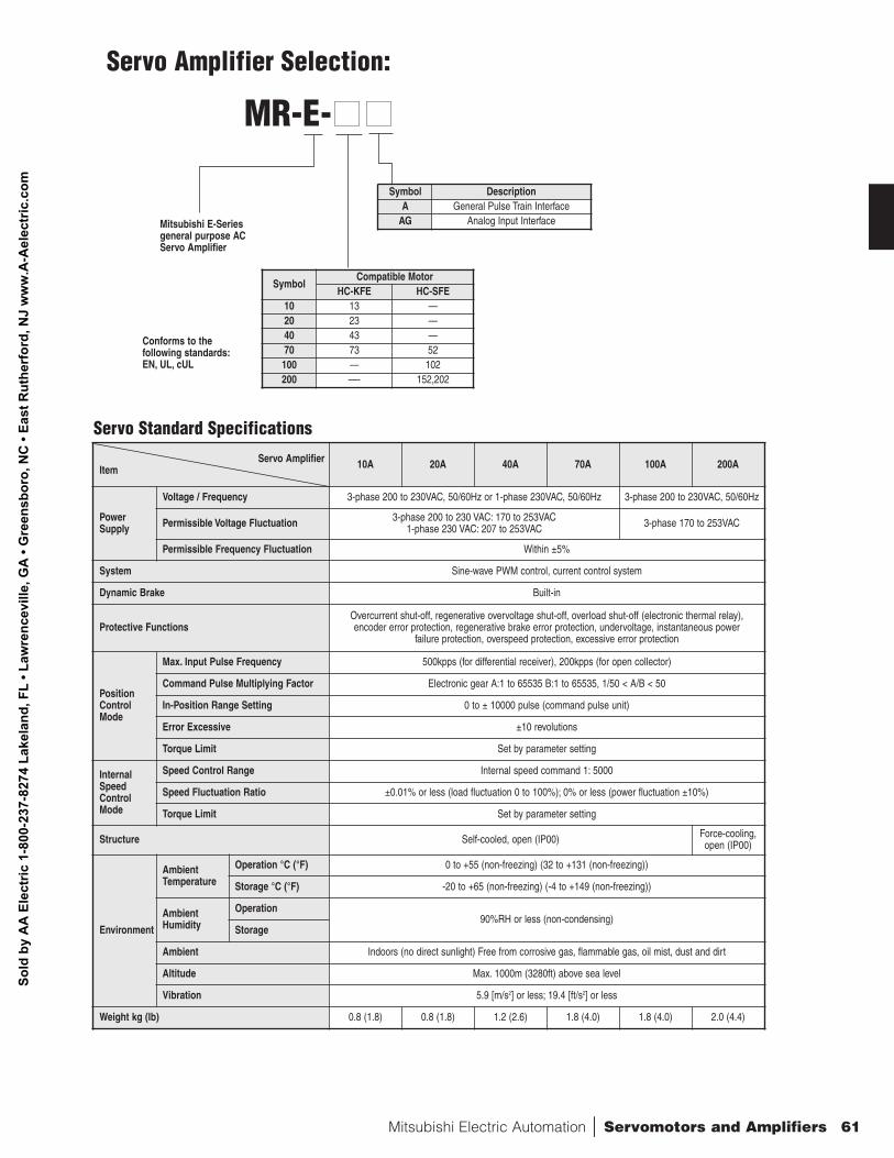
SymbolCompatible Motor
HC-KFE HC-SFE10 13 —20 23 —40 43 —70 73 52100 — 102200 —- 152,202
MR-E-nn nn
Mitsubishi E-Seriesgeneral purpose ACServo Amplifier
Conforms to the following standards:EN, UL, cUL
Symbol DescriptionA General Pulse Train Interface
AG Analog Input Interface
Servo AmplifierItem 10A 20A 40A 70A 100A 200A
PowerSupply
Voltage / Frequency 3-phase 200 to 230VAC, 50/60Hz or 1-phase 230VAC, 50/60Hz 3-phase 200 to 230VAC, 50/60Hz
Permissible Voltage Fluctuation 3-phase 200 to 230 VAC: 170 to 253VAC 1-phase 230 VAC: 207 to 253VAC 3-phase 170 to 253VAC
Permissible Frequency Fluctuation Within ±5%
System Sine-wave PWM control, current control system
Dynamic Brake Built-in
Protective FunctionsOvercurrent shut-off, regenerative overvoltage shut-off, overload shut-off (electronic thermal relay), encoder error protection, regenerative brake error protection, undervoltage, instantaneous power
failure protection, overspeed protection, excessive error protection
Position ControlMode
Max. Input Pulse Frequency 500kpps (for differential receiver), 200kpps (for open collector)
Command Pulse Multiplying Factor Electronic gear A:1 to 65535 B:1 to 65535, 1/50 < A/B < 50
In-Position Range Setting 0 to ± 10000 pulse (command pulse unit)
Error Excessive ±10 revolutions
Torque Limit Set by parameter setting
InternalSpeedControlMode
Speed Control Range Internal speed command 1: 5000
Speed Fluctuation Ratio ±0.01% or less (load fluctuation 0 to 100%); 0% or less (power fluctuation ±10%)
Torque Limit Set by parameter setting
Structure Self-cooled, open (IP00) Force-cooling,open (IP00)
Environment
AmbientTemperature
Operation °C (°F) 0 to +55 (non-freezing) (32 to +131 (non-freezing))
Storage °C (°F) -20 to +65 (non-freezing) (-4 to +149 (non-freezing))
AmbientHumidity
Operation90%RH or less (non-condensing)
Storage
Ambient Indoors (no direct sunlight) Free from corrosive gas, flammable gas, oil mist, dust and dirt
Altitude Max. 1000m (3280ft) above sea level
Vibration 5.9 [m/s2] or less; 19.4 [ft/s2] or less
Weight kg (lb) 0.8 (1.8) 0.8 (1.8) 1.2 (2.6) 1.8 (4.0) 1.8 (4.0) 2.0 (4.4)
Servo Standard Specifications
Servo Amplifier Selection:
Sold
by
AA
Ele
ctric
1-8
00-2
37-8
274
Lake
land
, FL
• Law
renc
evill
e, G
A •
Gre
ensb
oro,
NC
• Ea
st R
uthe
rfor
d, N
J w
ww
.A-A
elec
tric
.com
62
n
SE
RV
OM
OT
OR
S A
ND
AM
PL
IFIE
RS
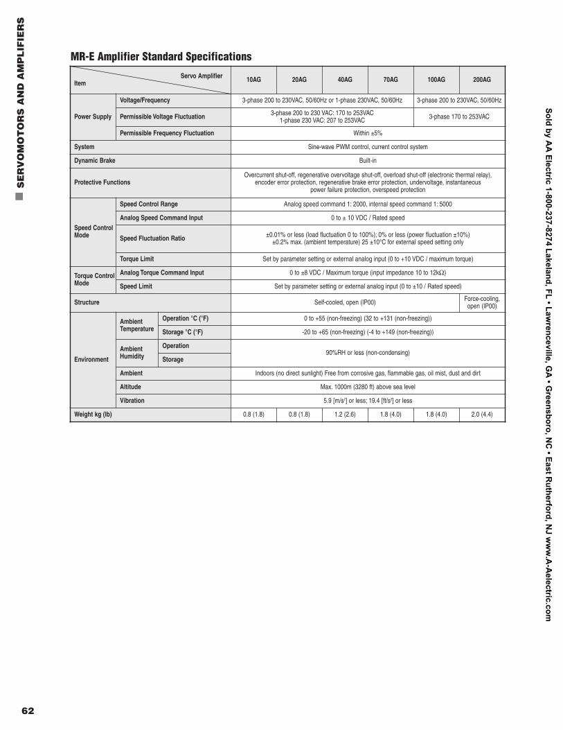
Servo AmplifierItem 10AG 20AG 40AG 70AG 100AG 200AG
Power Supply
Voltage/Frequency 3-phase 200 to 230VAC, 50/60Hz or 1-phase 230VAC, 50/60Hz 3-phase 200 to 230VAC, 50/60Hz
Permissible Voltage Fluctuation 3-phase 200 to 230 VAC: 170 to 253VAC 1-phase 230 VAC: 207 to 253VAC 3-phase 170 to 253VAC
Permissible Frequency Fluctuation Within ±5%
System Sine-wave PWM control, current control system
Dynamic Brake Built-in
Protective FunctionsOvercurrent shut-off, regenerative overvoltage shut-off, overload shut-off (electronic thermal relay),
encoder error protection, regenerative brake error protection, undervoltage, instantaneous power failure protection, overspeed protection
Speed ControlMode
Speed Control Range Analog speed command 1: 2000, internal speed command 1: 5000
Analog Speed Command Input 0 to ± 10 VDC / Rated speed
Speed Fluctuation Ratio ±0.01% or less (load fluctuation 0 to 100%); 0% or less (power fluctuation ±10%)±0.2% max. (ambient temperature) 25 ±10°C for external speed setting only
Torque Limit Set by parameter setting or external analog input (0 to +10 VDC / maximum torque)
Torque ControlMode
Analog Torque Command Input 0 to ±8 VDC / Maximum torque (input impedance 10 to 12kΩ)
Speed Limit Set by parameter setting or external analog input (0 to ±10 / Rated speed)
Structure Self-cooled, open (IP00) Force-cooling,open (IP00)
Environment
AmbientTemperature
Operation °C (°F) 0 to +55 (non-freezing) (32 to +131 (non-freezing))
Storage °C (°F) -20 to +65 (non-freezing) (-4 to +149 (non-freezing))
AmbientHumidity
Operation90%RH or less (non-condensing)
Storage
Ambient Indoors (no direct sunlight) Free from corrosive gas, flammable gas, oil mist, dust and dirt
Altitude Max. 1000m (3280 ft) above sea level
Vibration 5.9 [m/s2] or less; 19.4 [ft/s2] or less
Weight kg (lb) 0.8 (1.8) 0.8 (1.8) 1.2 (2.6) 1.8 (4.0) 1.8 (4.0) 2.0 (4.4)
MR-E Amplifier Standard Specifications
Sold by AA
Electric 1-800-237-8274 Lakeland, FL • Lawrenceville, G
A • G
reensboro, NC
• East Rutherford, N
J ww
w.A
-Aelectric.com
Mitsubishi Electric Automation | Servomotors and Amplifiers 63
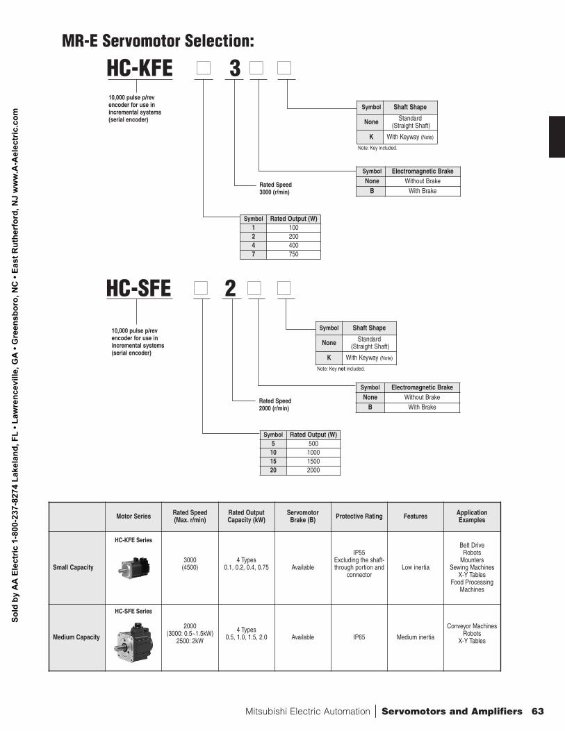
HC-KFE nn
3 nn nn
10,000 pulse p/revencoder for use inincremental systems(serial encoder)
Rated Speed3000 (r/min)
Symbol Rated Output (W)1 1002 2004 4007 750
Note: Key included.
Symbol Shaft Shape
None Standard(Straight Shaft)
K With Keyway (Note)
Symbol Electromagnetic BrakeNone Without Brake
B With Brake
HC-SFE nn
2 nn nn
10,000 pulse p/revencoder for use inincremental systems(serial encoder)
Rated Speed2000 (r/min)
Symbol Rated Output (W)5 50010 100015 150020 2000
Note: Key not included.
Symbol Shaft Shape
None Standard(Straight Shaft)
K With Keyway (Note)
Symbol Electromagnetic BrakeNone Without Brake
B With Brake
Motor Series Rated Speed (Max. r/min)
Rated OutputCapacity (kW)
Servomotor Brake (B) Protective Rating Features Application
Examples
Small Capacity3000
(4500)4 Types
0.1, 0.2, 0.4, 0.75 Available
IP55Excluding the shaft-through portion and
connectorLow inertia
Belt DriveRobots
MountersSewing Machines
X-Y TablesFood Processing
Machines
Medium Capacity
2000(3000: 0.5~1.5kW)
2500: 2kW
4 Types0.5, 1.0, 1.5, 2.0 Available IP65 Medium inertia
Conveyor MachinesRobots
X-Y Tables
HC-KFE Series
HC-SFE Series
MR-E Servomotor Selection:
Sold
by
AA
Ele
ctric
1-8
00-2
37-8
274
Lake
land
, FL
• Law
renc
evill
e, G
A •
Gre
ensb
oro,
NC
• Ea
st R
uthe
rfor
d, N
J w
ww
.A-A
elec
tric
.com
64
n
SE
RV
OM
OT
OR
S A
ND
AM
PL
IFIE
RS
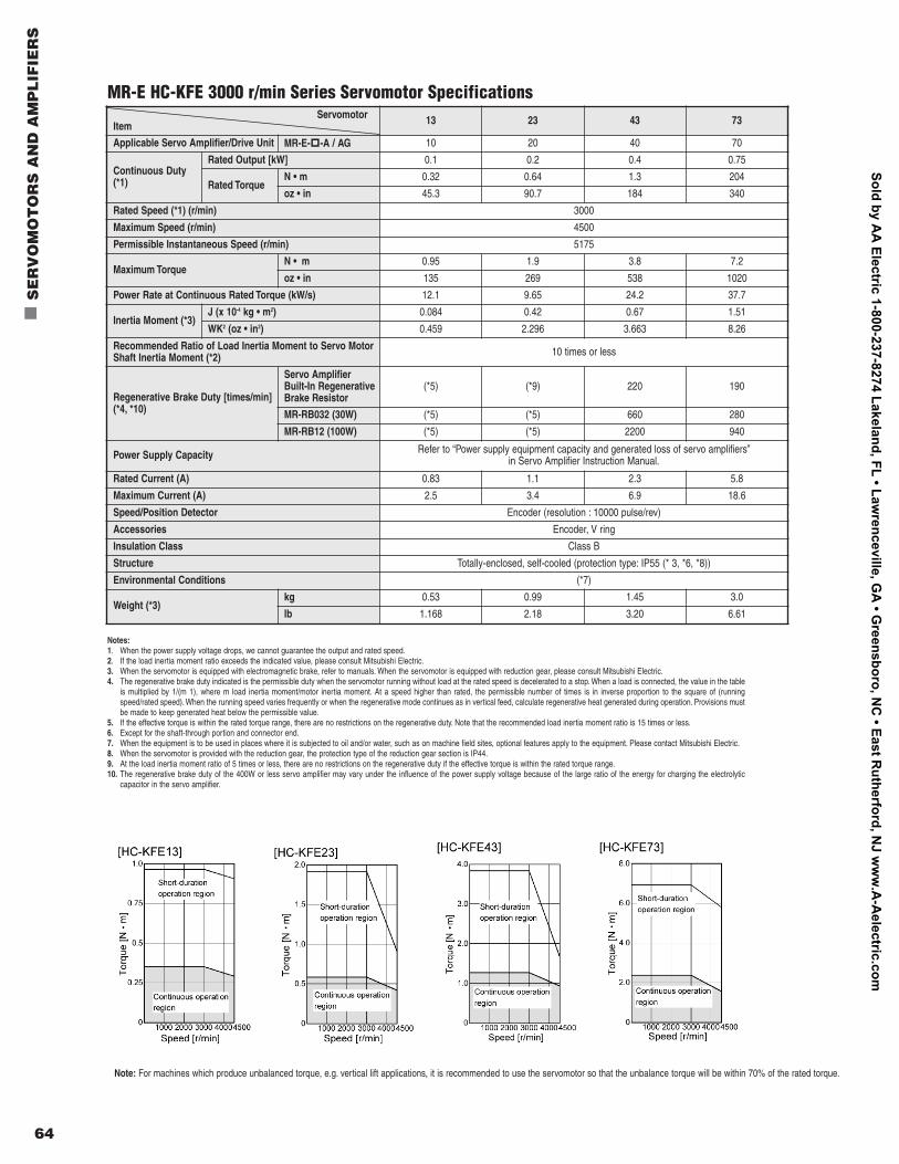
ServomotorItem 13 23 43 73
Applicable Servo Amplifier/Drive Unit MR-E-p
-A / AG 10 20 40 70
Continuous Duty(*1)
Rated Output [kW] 0.1 0.2 0.4 0.75
Rated TorqueN • m 0.32 0.64 1.3 204
oz • in 45.3 90.7 184 340
Rated Speed (*1) (r/min) 3000
Maximum Speed (r/min) 4500
Permissible Instantaneous Speed (r/min) 5175
Maximum TorqueN • m 0.95 1.9 3.8 7.2
oz • in 135 269 538 1020
Power Rate at Continuous Rated Torque (kW/s) 12.1 9.65 24.2 37.7
Inertia Moment (*3)J (x 10-4 kg • m2) 0.084 0.42 0.67 1.51
WK2 (oz • in2) 0.459 2.296 3.663 8.26
Recommended Ratio of Load Inertia Moment to Servo Motor Shaft Inertia Moment (*2) 10 times or less
Regenerative Brake Duty [times/min](*4, *10)
Servo Amplifier Built-In RegenerativeBrake Resistor
(*5) (*9) 220 190
MR-RB032 (30W) (*5) (*5) 660 280
MR-RB12 (100W) (*5) (*5) 2200 940
Power Supply Capacity Refer to “Power supply equipment capacity and generated loss of servo amplifiers”in Servo Amplifier Instruction Manual.
Rated Current (A) 0.83 1.1 2.3 5.8
Maximum Current (A) 2.5 3.4 6.9 18.6
Speed/Position Detector Encoder (resolution : 10000 pulse/rev)
Accessories Encoder, V ring
Insulation Class Class B
Structure Totally-enclosed, self-cooled (protection type: IP55 (* 3, *6, *8))
Environmental Conditions (*7)
Weight (*3)kg 0.53 0.99 1.45 3.0
lb 1.168 2.18 3.20 6.61
MR-E HC-KFE 3000 r/min Series Servomotor Specifications
Notes:1. When the power supply voltage drops, we cannot guarantee the output and rated speed.2. If the load inertia moment ratio exceeds the indicated value, please consult Mitsubishi Electric.3. When the servomotor is equipped with electromagnetic brake, refer to manuals. When the servomotor is equipped with reduction gear, please consult Mitsubishi Electric.4. The regenerative brake duty indicated is the permissible duty when the servomotor running without load at the rated speed is decelerated to a stop. When a load is connected, the value in the table
is multiplied by 1/(m 1), where m load inertia moment/motor inertia moment. At a speed higher than rated, the permissible number of times is in inverse proportion to the square of (runningspeed/rated speed). When the running speed varies frequently or when the regenerative mode continues as in vertical feed, calculate regenerative heat generated during operation. Provisions mustbe made to keep generated heat below the permissible value.
5. If the effective torque is within the rated torque range, there are no restrictions on the regenerative duty. Note that the recommended load inertia moment ratio is 15 times or less.6. Except for the shaft-through portion and connector end.7. When the equipment is to be used in places where it is subjected to oil and/or water, such as on machine field sites, optional features apply to the equipment. Please contact Mitsubishi Electric.8. When the servomotor is provided with the reduction gear, the protection type of the reduction gear section is IP44.9. At the load inertia moment ratio of 5 times or less, there are no restrictions on the regenerative duty if the effective torque is within the rated torque range.10. The regenerative brake duty of the 400W or less servo amplifier may vary under the influence of the power supply voltage because of the large ratio of the energy for charging the electrolytic
capacitor in the servo amplifier.
Note: For machines which produce unbalanced torque, e.g. vertical lift applications, it is recommended to use the servomotor so that the unbalance torque will be within 70% of the rated torque.
Sold by AA
Electric 1-800-237-8274 Lakeland, FL • Lawrenceville, G
A • G
reensboro, NC
• East Rutherford, N
J ww
w.A
-Aelectric.com
Mitsubishi Electric Automation | Servomotors and Amplifiers 65
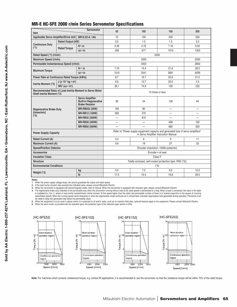
ServomotorItem 52 102 152 202
Applicable Servo Amplifier/Drive Unit MR-E-p
-A / AG 70 100 200 200
Continuous Duty(*1)
Rated Output [kW] 0.5 1.0 1.5 2.0
Rated TorqueN • m 2.39 4.78 7.16 9.55
oz • in 339 677 1015 1353
Rated Speed (*1) (r/min) 2000
Maximum Speed (r/min) 3000 2500
Permissible Instantaneous Speed (r/min) 3450 2850
Maximum TorqueN • m 7.16 14.4 21.6 28.5
oz • in 1015 2041 3061 4039
Power Rate at Continuous Rated Torque (kW/s) 8.7 16.7 25.6 21.5
Inertia Moment (*3)J (x 10-4 kg • m2) 6.6 13.7 20.0 4.5
WK2 (oz • in2) 36.1 74.9 109 232
Recommended Ratio of Load Inertia Moment to Servo Motor Shaft Inertia Moment (*2) 15 times or less
Regenerative Brake Duty [times/min](*4)
Servo AmplifierBuilt-In RegenerativeBrake Resistor
56 54 136 64
MR-RB032 (30W) 165 80 — —
MR-RB12 (100W) 560 270 — —
MR-RB32 (300W) — 810 — —
MR-RB30 (300W) — — 408 192
MR-RB50 (500W) — — 680 320
Power Supply Capacity Refer to "Power supply equipment capacity and generated loss of servo amplifiers" in Servo Amplifier Instruction Manual.
Rated Current (A) 3.2 6 9 11
Maximum Current (A) 9.6 18 27 33
Speed/Position Detector Encoder (resolution: 10000 pulse/rev)
Accessories Encoder • oil seal
Insulation Class Class F
Structure Totally enclosed, self-cooled (protection type: IP65 (*6))
Environmental Conditions (*5)
Weight (*3)kg 5.0 7.0 9.0 12.0
lb 11.0 15.4 19.8 26.5
MR-E HC-SFE 2000 r/min Series Servomotor Specifications
Notes:1. When the power supply voltage drops, we cannot guarantee the output and rated speed.2. If the load inertia moment ratio exceeds the indicated value, please consult Mitsubishi Electric.3. When the servomotor is equipped with electromagnetic brake, refer to manual. When the servomotor is equipped with reduction gear, please consult Mitsubishi Electric.4. The regenerative brake duty indicated is the permissible duty when the servomotor running without load at the rated speed is decelerated to a stop. When a load is connected, the value in the table
is multiplied by 1/(m 1), where m load inertia moment/motor inertia moment. At the speed higher than the rated, the permissible number of times is in inverse proportion to the square of (runningspeed/rated speed). When the running speed varies frequently or when the regenerative mode continues as in vertical feed, calculate regenerative heat generated during operation. Provisions mustbe made to keep this generated heat below the permissible value.
5. When the equipment is to be used in places where it is subjected to oil and/or water, such as on machine field sites, optional features apply to the equipment. Please contact Mitsubishi Electric.6. When the servo motor is provided with the reduction gear, the protection type of the reduction gear section is IP44.
Note: For machines which produce unbalanced torque, e.g. vertical lift applications, it is recommended to use the servomotor so that the unbalance torque will be within 70% of the rated torque.
Sold
by
AA
Ele
ctric
1-8
00-2
37-8
274
Lake
land
, FL
• Law
renc
evill
e, G
A •
Gre
ensb
oro,
NC
• Ea
st R
uthe
rfor
d, N
J w
ww
.A-A
elec
tric
.com
66
n
SE
RV
OM
OT
OR
S A
ND
AM
PL
IFIE
RS
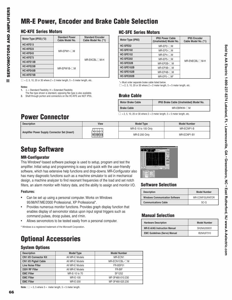
MR-E Power, Encoder and Brake Cable SelectionHC-KFE Series Motors HC-SFE Series Motors
Motor Type (IP55) (*2) Standard Power Cable Model No.
Standard Encoder Cable Model No. (*1)
HC-KFE13
MR-EPW1- nnM
MR-EKCBL nn M-H
HC-KFE23
HC-KFE43
HC-KFE73
HC-KFE13B
MR-EPW1B- nn MHC-KFE23B
HC-KFE43B
HC-KFE73B
nn = 2, 5, 10, 20 or 30 where 2 = 2 meter length, 5 = 5 meter length, etc.
Motor Type (IP65) IP65 Power Cable(Unshielded) Model No.
IP65 Encoder Cable Model No. (*1)
HC-SFE52 MR-EP2- nnM
MR-ENECBL nn M-H
HC-SFE102 MR-EP3- nnMHC-SFE152 MR-EP4- nnMHC-SFE202 MR-EP5- nnMHC-SFE52B MR-EP2B- nnMHC-SFE102B MR-EP3B- nnMHC-SFE152B MR-EP4B- nnMHC-SFE202B MR-EP5- nn M*
*= Must order separate brake cable listed below.nn = 2, 5, 10, 20 or 30 where 2 = 2 meter length, 5 = 5 meter length, etc.
Setup SoftwareMR-ConfiguratorThis Windows®-based software package is used to setup, program and test theamplifier. Initial setup and programming is easy and quick with the user-friendly software, which has extensive help functions and drop-downs. MR-Configurator alsohas many diagnostic functions such as a machine simulator to aid in mechanicaldesign, a machine analyzer to find resonant frequencies of the load and set notchfilters, an alarm monitor with history data, and the ability to assign and monitor I/O.
Features:
• Can be set up using a personal computer. Works on Windows95/98/NT/ME/2000 Professional, XP Professional*.
• Provides numerous monitor functions. Provides graph display function thatenables display of servomotor status upon input signal triggers such as command pulses, droop pulses, and r/min.
• Allows servomotors to be tested easily from a personal computer.
* Windows is a registered trademark of the Microsoft Corporation.
Description Model Number
Windows Communication Software MR-CONFIGURATOR
Communications Cable SC-Q
Software Selection
Hardware Description Model Number
MR-E-A/AG Instruction Manual SH(NA)030031
EMC Guidelines (Servo) Manual IB(NA)67310
Manual Selection
Notes:1. -L = Standard Flexibility; H = Extended Flexibility
The flex type shown is standard, opposing flex type is also available.2. Shaft through portion and connectors on the HC-KFE are NOT IP55.
Optional AccessoriesSystem Options
Description Model Type Model NumberCN1 I/O Connector Kit All MR-E Models MR-ECN1CN1 I/O Pigtail Cable All MR-E Models MR-ECN1CBL- nn MLine Noise Filter All MR-E Models FR-BSF01230V RF Filter All MR-E Models FR-BIFEMC Filter MR-E-10 to 70 SF1252EMC Filter MR-E-100 MF-3F480-010.230EMC Filter MR-E-200 MF-3F480-025.230
Note: nn = 3, 5 where 3 = meter length, 5 = 5 meter length.
Brake Cable
nn = 2, 5, 10, 20 or 30 where 2 = 2 meter length, 5 = 5 meter length, etc.
Motor Brake Cable IP65 Brake Cable (Unshielded) Model No.
Brake Cable MR-EBRKW- nnM
Power ConnectorDescription View Model Type Model Number
Amplifier Power Supply Connector Set (Insert)MR-E-10 to 100 Only MR-ECNP1-B
MR-E-200 Only MR-ECNP1-B1
Sold by AA
Electric 1-800-237-8274 Lakeland, FL • Lawrenceville, G
A • G
reensboro, NC
• East Rutherford, N
J ww
w.A
-Aelectric.com
Mitsubishi Electric Automation | Servomotors and Amplifiers 67
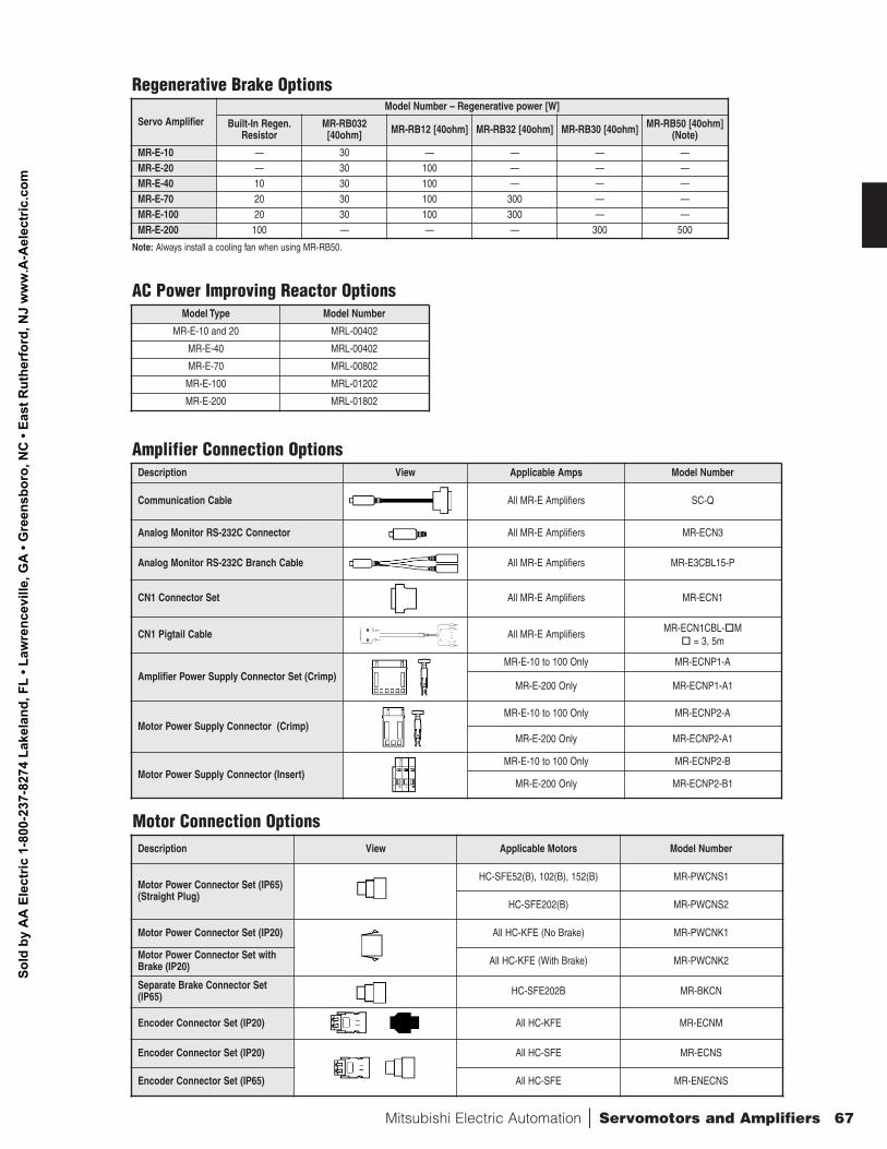
Motor Connection OptionsDescription View Applicable Motors Model Number
Motor Power Connector Set (IP65)(Straight Plug)
HC-SFE52(B), 102(B), 152(B) MR-PWCNS1
HC-SFE202(B) MR-PWCNS2
Motor Power Connector Set (IP20) All HC-KFE (No Brake) MR-PWCNK1
Motor Power Connector Set withBrake (IP20) All HC-KFE (With Brake) MR-PWCNK2
Separate Brake Connector Set(IP65) HC-SFE202B MR-BKCN
Encoder Connector Set (IP20) All HC-KFE MR-ECNM
Encoder Connector Set (IP20) All HC-SFE MR-ECNS
Encoder Connector Set (IP65) All HC-SFE MR-ENECNS
Regenerative Brake Options
AC Power Improving Reactor Options
Amplifier Connection Options
Note: Always install a cooling fan when using MR-RB50.
Servo AmplifierModel Number – Regenerative power [W]
Built-In Regen.Resistor
MR-RB032[40ohm] MR-RB12 [40ohm] MR-RB32 [40ohm] MR-RB30 [40ohm] MR-RB50 [40ohm]
(Note)
MR-E-10 — 30 — — — —MR-E-20 — 30 100 — — —MR-E-40 10 30 100 — — —MR-E-70 20 30 100 300 — —MR-E-100 20 30 100 300 — —MR-E-200 100 — — — 300 500
Model Type Model Number
MR-E-10 and 20 MRL-00402
MR-E-40 MRL-00402
MR-E-70 MRL-00802
MR-E-100 MRL-01202
MR-E-200 MRL-01802
Description View Applicable Amps Model Number
Communication Cable All MR-E Amplifiers SC-Q
Analog Monitor RS-232C Connector All MR-E Amplifiers MR-ECN3
Analog Monitor RS-232C Branch Cable All MR-E Amplifiers MR-E3CBL15-P
CN1 Connector Set All MR-E Amplifiers MR-ECN1
CN1 Pigtail Cable All MR-E Amplifiers MR-ECN1CBL-o
Mo
= 3, 5m
Amplifier Power Supply Connector Set (Crimp)MR-E-10 to 100 Only MR-ECNP1-A
MR-E-200 Only MR-ECNP1-A1
Motor Power Supply Connector (Crimp)MR-E-10 to 100 Only MR-ECNP2-A
MR-E-200 Only MR-ECNP2-A1
Motor Power Supply Connector (Insert)MR-E-10 to 100 Only MR-ECNP2-B
MR-E-200 Only MR-ECNP2-B1
Sold
by
AA
Ele
ctric
1-8
00-2
37-8
274
Lake
land
, FL
• Law
renc
evill
e, G
A •
Gre
ensb
oro,
NC
• Ea
st R
uthe
rfor
d, N
J w
ww
.A-A
elec
tric
.com
68
n
SE
RV
OM
OT
OR
S A
ND
AM
PL
IFIE
RS
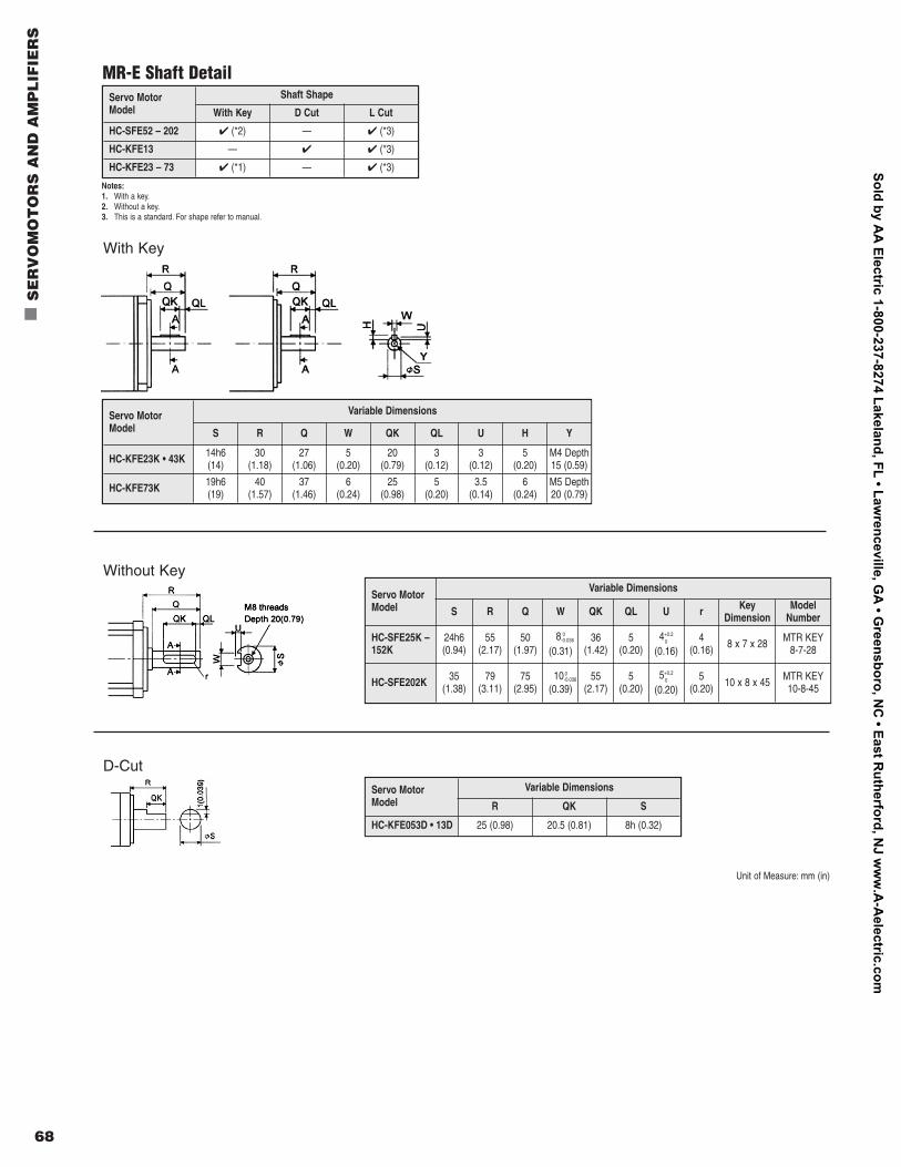
Servo MotorModel
Shaft Shape
With Key D Cut L Cut
HC-SFE52 – 202 4 (*2) — 4 (*3)
HC-KFE13 — 4 4 (*3)
HC-KFE23 – 73 4 (*1) — 4 (*3)
Servo MotorModel
Variable Dimensions
R QK S
HC-KFE053D • 13D 25 (0.98) 20.5 (0.81) 8h (0.32)
MR-E Shaft Detail
Servo Motor Model
Variable Dimensions
S R Q W QK QL U H Y
HC-KFE23K • 43K 14h6 (14)
30(1.18)
27(1.06)
5(0.20)
20(0.79)
3(0.12)
3(0.12)
5(0.20)
M4 Depth15 (0.59)
HC-KFE73K 19h6(19)
40(1.57)
37(1.46)
6(0.24)
25(0.98)
5(0.20)
3.5(0.14)
6(0.24)
M5 Depth20 (0.79)
Servo Motor Model
Variable Dimensions
S R Q W QK QL U r KeyDimension
ModelNumber
HC-SFE25K –152K
24h6 (0.94)
55(2.17)
50(1.97)
8 0-0.036
(0.31)36
(1.42)5
(0.20)4+0.2
0
(0.16)4
(0.16) 8 x 7 x 28 MTR KEY8-7-28
HC-SFE202K 35(1.38)
79(3.11)
75(2.95)
10 0-0.036
(0.39)55
(2.17)5
(0.20)5+0.2
0
(0.20)5
(0.20) 10 x 8 x 45 MTR KEY10-8-45
Notes:1. With a key.2. Without a key.3. This is a standard. For shape refer to manual.
With Key
Without Key
D-Cut
Unit of Measure: mm (in)
Sold by AA
Electric 1-800-237-8274 Lakeland, FL • Lawrenceville, G
A • G
reensboro, NC
• East Rutherford, N
J ww
w.A
-Aelectric.com
Mitsubishi Electric Automation | Servomotors and Amplifiers 69
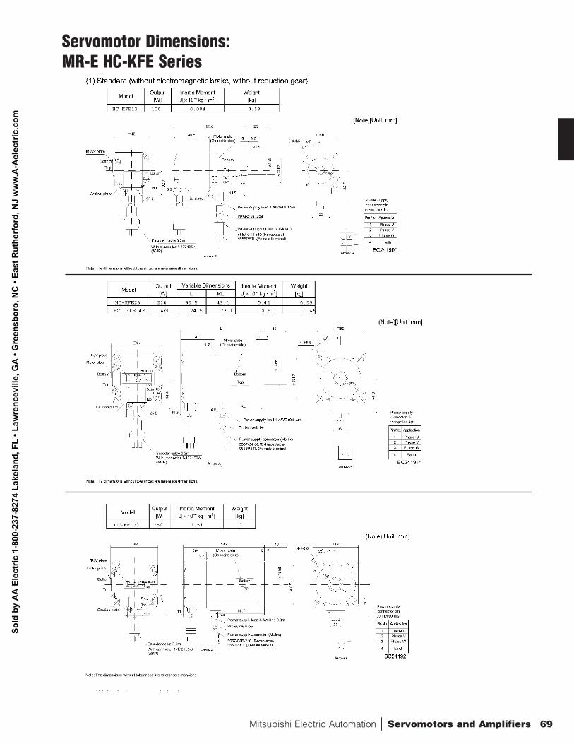
Servomotor Dimensions:MR-E HC-KFE Series
Sold
by
AA
Ele
ctric
1-8
00-2
37-8
274
Lake
land
, FL
• Law
renc
evill
e, G
A •
Gre
ensb
oro,
NC
• Ea
st R
uthe
rfor
d, N
J w
ww
.A-A
elec
tric
.com
70
n
SE
RV
OM
OT
OR
S A
ND
AM
PL
IFIE
RS
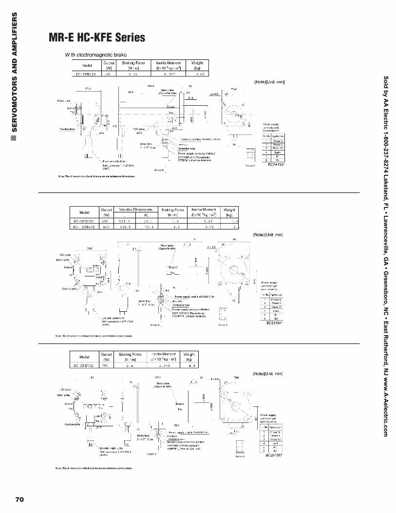
MR-E HC-KFE Series
Sold by AA
Electric 1-800-237-8274 Lakeland, FL • Lawrenceville, G
A • G
reensboro, NC
• East Rutherford, N
J ww
w.A
-Aelectric.com
Mitsubishi Electric Automation | Servomotors and Amplifiers 71
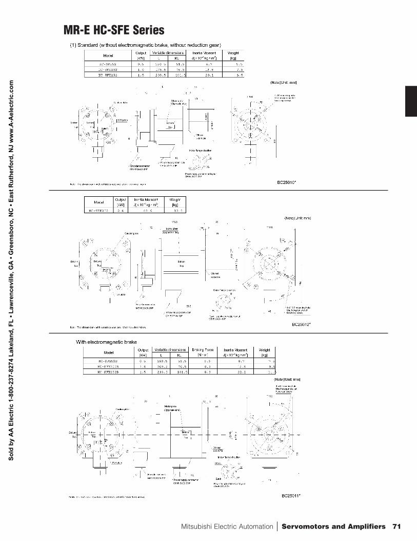
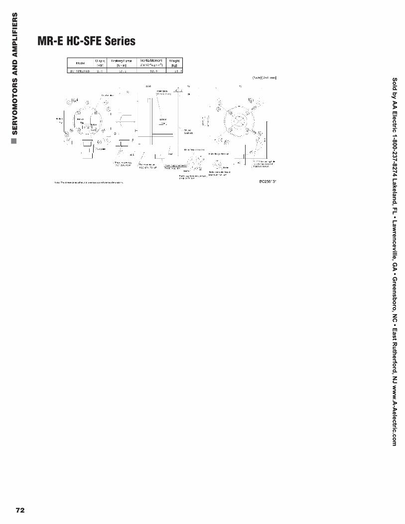
MR-E HC-SFE Series
Sold
by
AA
Ele
ctric
1-8
00-2
37-8
274
Lake
land
, FL
• Law
renc
evill
e, G
A •
Gre
ensb
oro,
NC
• Ea
st R
uthe
rfor
d, N
J w
ww
.A-A
elec
tric
.com
72
n
SE
RV
OM
OT
OR
S A
ND
AM
PL
IFIE
RS
MR-E HC-SFE Series
Sold by AA
Electric 1-800-237-8274 Lakeland, FL • Lawrenceville, G
A • G
reensboro, NC
• East Rutherford, N
J ww
w.A
-Aelectric.com
Mitsubishi Electric Automation | Servomotors and Amplifiers 73
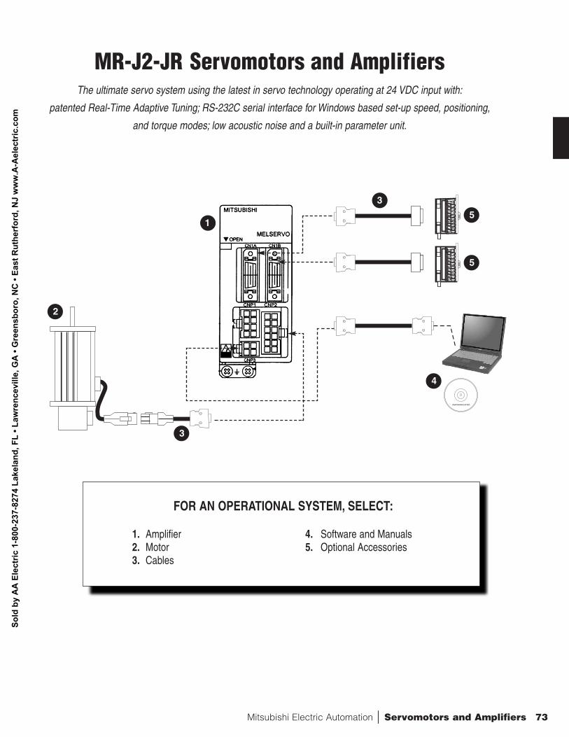
FOR AN OPERATIONAL SYSTEM, SELECT:
1. Amplifier 4. Software and Manuals2. Motor 5. Optional Accessories3. Cables
MR-J2-JR Servomotors and AmplifiersThe ultimate servo system using the latest in servo technology operating at 24 VDC input with:
patented Real-Time Adaptive Tuning; RS-232C serial interface for Windows based set-up speed, positioning,
and torque modes; low acoustic noise and a built-in parameter unit.
1
2
3
4
3
5
5
Sold
by
AA
Ele
ctric
1-8
00-2
37-8
274
Lake
land
, FL
• Law
renc
evill
e, G
A •
Gre
ensb
oro,
NC
• Ea
st R
uthe
rfor
d, N
J w
ww
.A-A
elec
tric
.com
74
n
SE
RV
OM
OT
OR
S A
ND
AM
PL
IFIE
RS
MR-J2-JR Servo Motor Selection:HC-AQ0nn35nnD
Symbol DescriptionNone No brake installed
B With an electromagnetic brake installedSymbol Description1 10 Watts2 20 Watts3 30 Watts
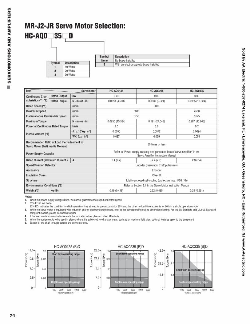
Item Servomotor HC-AQ0135 HC-AQ0235 HC-AQ0335
Continuous Char-acteristics (*1, *2)
Rated Output kW 0.01 0.02 0.03
Rated Torque N · m (oz · in) 0.0318 (4.503) 0.0637 (9.021) 0.0955 (13.524)
Rated Speed (*1) r/min 3000
Maximum Speed r/min 5000 4500
Instantaneous Permissible Speed r/min 5750 5175
Maximum Torque N · m (oz · in) 0.0955 (13.524) 0.191 (27.048) 0.287 (40.643)
Power at Continuous Rated Torque kW/s 2.0 5.6 9.7
Inertia Moment (*4)J [ x 104kg · m2] 0.0050 0.0072 0.0094
WK2 [oz · in2] 0.027 0.039 0.051
Recommended Ratio of Load Inertia Moment to Servo Motor Shaft Inertia Moment
30 times or less
Power Supply CapacityRefer to “Power supply capacity and generated loss of servo amplifier” in the
Servo Amplifier Instruction Manual
Rated Current (Maximum Current ) A 2.4 (7.7) 2.4 (7.7) 2.3 (7.4)
Speed/Position Detector Encoder (resolution: 8192 pulses/rev)
Accessory Encoder
Insulation Class Class B
Structure Totally-enclosed self-cooling (protection type: IP55 (*6))
Environmental Conditions (*5) Refer to Section 2.1 in the Servo Motor Instruction Manual
Weight (*3) kg (lb) 0.19 (0.419) 0.22 (0.485) 0.25 (0.551)
HC-AQ0135 (B)D HC-AQ0235 (B)D HC-AQ0335 (B)D
0.05
0.025
01000 5000
0.075
0.1
Torq
ue (i
n-oz
)
14.1
0
Torq
ue (N
•m)
10.6
7.0
3.5
Rotation speed (rpm)
Short term operating range
Continuous operating range
2000 3000 4000
0.1
0.05
01000 5000
0.15
0.2
Torq
ue (i
n-oz
)
28.3
0
Torq
ue (N
•m)
21.2
14.1
7.0
Rotation speed (rpm)
Continuous operating range
2000 3000 4000
0.1
01000 4500
0.2
0.3
Torq
ue (i
n-oz
)
42.5
0
Torq
ue (N
•m)
28.3
14.1
Rotation speed (rpm)
Continuous operating range
2000 3000 4000
Short term operating range
Short term operating range
Notes:1. When the power supply voltage drops, we cannot guarantee the output and rated speed.2. 80% ED at low noise.
80% ED: Indicates the condition in which operation time at read torque accounts for 80% and the other no load time accounts for 20% in a single operation cycle.3. When the servo motor is equipped with reduction gear or electromagnetic brake, refer to the corresponding outline dimension drawing. For the EN Standard and UL/cUL Standard
compliant models, please contact Mitsubishi.4. If the load inertia moment ratio exceeds the indicated value, please contact Mitsubishi.5. When the equipment is to be used in places where it is subjected to oil and/or water, such as on machine field sites, optional features apply to the equipment.6. Except for the shaft-through portion and connector end.
Sold by AA
Electric 1-800-237-8274 Lakeland, FL • Lawrenceville, G
A • G
reensboro, NC
• East Rutherford, N
J ww
w.A
-Aelectric.com
Mitsubishi Electric Automation | Servomotors and Amplifiers 75
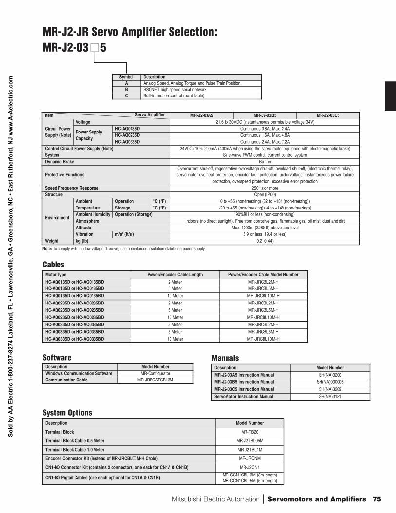
MR-J2-JR Servo Amplifier Selection:MR-J2-03 nn5
Symbol DescriptionA Analog Speed, Analog Torque and Pulse Train PositionB SSCNET high speed serial networkC Built-in motion control (point table)
Item Servo Amplifier MR-J2-03A5 MR-J2-03B5 MR-J2-03C5
Circuit PowerSupply (Note)
Voltage 21.6 to 30VDC (instantaneous permissible voltage 34V)
Power SupplyCapacity
HC-AQ0135D Continuous 0.8A, Max. 2.4AHC-AQ0235D Continuous 1.6A, Max. 4.8AHC-AQ0335D Continuous 2.4A, Max. 7.2A
Control Circuit Power Supply (Note) 24VDC+10% 200mA (400mA when using the servo motor equipped with electromagnetic brake)System Sine-wave PWM control, current control system Dynamic Brake Built-in
Protective FunctionsOvercurrent shut-off, regenerative overvoltage shut-off, overload shut-off, (electronic thermal relay), servo motor overheat protection, encoder fault protection, undervoltage, instantaneous power failure
protection, overspeed protection, excessive error protection Speed Frequency Response 250Hz or moreStructure Open (IP00)
Environment
Ambient Temperature
Operation °C (°F) 0 to +55 (non-freezing) (32 to +131 (non-freezing))Storage °C (°F) -20 to +65 (non-freezing) (-4 to +149 (non-freezing))
Ambient Humidity Operation (Storage) 90%RH or less (non-condensing)Atmosphere Indoors (no direct sunlight), Free from corrosive gas, flammable gas, oil mist, dust and dirtAltitude Max. 1000m (3280 ft) above sea levelVibration m/s2 (ft/s2) 5.9 or less (19.4 or less)
Weight kg (lb) 0.2 (0.44)
Note: To comply with the low voltage directive, use a reinforced insulation stabilizing power supply.
Cables
SoftwareDescription Model NumberWindows Communication Software MR-ConfiguratorCommunication Cable MR-JRPCATCBL3M
Manuals
Motor Type Power/Encoder Cable Length Power/Encoder Cable Model Number
HC-AQ0135D or HC-AQ0135BD 2 Meter MR-JRCBL2M-HHC-AQ0135D or HC-AQ0135BD 5 Meter MR-JRCBL5M-H
HC-AQ0135D or HC-AQ0135BD 10 Meter MR-JRCBL10M-H
HC-AQ0235D or HC-AQ0235BD 2 Meter MR-JRCBL2M-H
HC-AQ0235D or HC-AQ0235BD 5 Meter MR-JRCBL5M-H
HC-AQ0235D or HC-AQ0235BD 10 Meter MR-JRCBL10M-H
HC-AQ0335D or HC-AQ0335BD 2 Meter MR-JRCBL2M-H
HC-AQ0335D or HC-AQ0335BD 5 Meter MR-JRCBL5M-H
HC-AQ0335D or HC-AQ0335BD 10 Meter MR-JRCBL10M-H
Description Model NumberMR-J2-03A5 Instruction Manual SH(NA)3200
MR-J2-03B5 Instruction Manual SH(NA)030005
MR-J2-03C5 Instruction Manual SH(NA)3209
ServoMotor Instruction Manual SH(NA)3181
System OptionsDescription Model Number
Terminal Block MR-TB20
Terminal Block Cable 0.5 Meter MR-J2TBL05M
Terminal Block Cable 1.0 Meter MR-J2TBL1M
Encoder Connector Kit (instead of MR-JRCBLo
M-H Cable) MR-JRCNM
CN1-I/O Connector Kit (contains 2 connectors, one each for CN1A & CN1B) MR-J2CN1
CN1-I/O Pigtail Cables (one each optional for CN1A & CN1B)MR-CCN1CBL-3M (3m length)MR-CCN1CBL-5M (5m length)
Sold
by
AA
Ele
ctric
1-8
00-2
37-8
274
Lake
land
, FL
• Law
renc
evill
e, G
A •
Gre
ensb
oro,
NC
• Ea
st R
uthe
rfor
d, N
J w
ww
.A-A
elec
tric
.com
76
n
SE
RV
OM
OT
OR
S A
ND
AM
PL
IFIE
RS
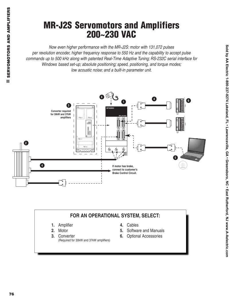
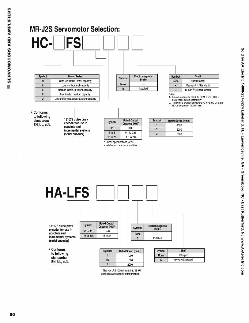
MR-J2S Servomotors and Amplifiers200~230 VAC
Now even higher performance with the MR-J2S: motor with 131,072 pulses per revolution encoder, higher frequency response to 550 Hz and the capability to accept pulse
commands up to 500 kHz along with patented Real-Time Adaptive Tuning; RS-232C serial interface for Windows based set-up; absolute positioning; speed, positioning, and torque modes;
low acoustic noise; and a built-in parameter unit.
FOR AN OPERATIONAL SYSTEM, SELECT:
1. Amplifier 4. Cables2. Motor 5. Software and Manuals3. Converter 6. Optional Accessories
(Required for 30kW and 37kW amplifiers)
2
3
6
14 6
4 If motor has brake,connect to customer’sBrake Control Circuit.
5
Converter requiredfor 30kW and 37kW
amplifiers
TE1-2
TE1-1
TE2-1 TE2-2
Sold by AA
Electric 1-800-237-8274 Lakeland, FL • Lawrenceville, G
A • G
reensboro, NC
• East Rutherford, N
J ww
w.A
-Aelectric.com
Mitsubishi Electric Automation | Servomotors and Amplifiers 77
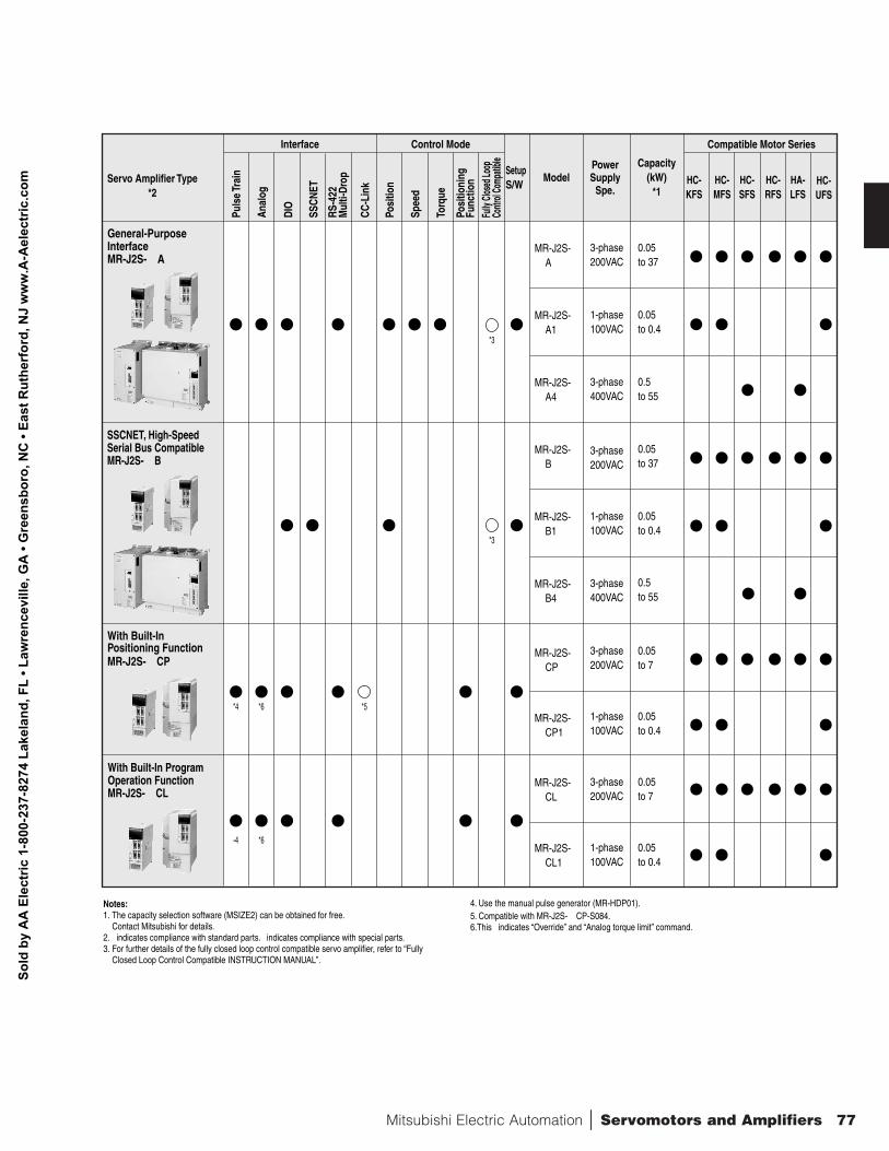
4. Use the manual pulse generator (MR-HDP01).5. Compatible with MR-J2S-oCP-S084.6.This l indicates “Override” and “Analog torque limit” command.
Servo Amplifier Type*2
Interface Control Mode Compatible Motor Series
General-PurposeInterfaceMR-J2S-oA
SSCNET, High-SpeedSerial Bus CompatibleMR-J2S-oB
With Built-In ProgramOperation FunctionMR-J2S-oCL
With Built-InPositioning FunctionMR-J2S-oCP
Notes:1. The capacity selection software (MSIZE2) can be obtained for free.
Contact Mitsubishi for details.2. l indicates compliance with standard parts. indicates compliance with special parts.3. For further details of the fully closed loop control compatible servo amplifier, refer to “Fully
Closed Loop Control Compatible INSTRUCTION MANUAL”.
MR-J2S-oA
0.05to 37
0.05to 0.4
0.05to 37
0.05to 0.4
0.05to 7
0.05to 0.4
0.5to 55
0.5to 55
3-phase200VAC
1-phase100VAC
3-phase400VAC
3-phase200VAC
1-phase100VAC
3-phase400VAC
3-phase200VAC
1-phase100VAC
0.05to 7
3-phase200VAC
MR-J2S-oA1
MR-J2S-oA4
MR-J2S-oB
MR-J2S-oB1
MR-J2S-oB4
MR-J2S-oCP
MR-J2S-oCP1
MR-J2S-oCL
0.05to 0.4
1-phase100VAC
MR-J2S-oCL1
Puls
e Tr
ain
Anal
og
Posi
tion
Spee
d
Torq
ue
Posi
tioni
ngFu
nctio
nFu
lly Cl
osed
Loop
Co
ntrol
Comp
atible
SetupS/W HC-
KFSHC-MFS
HC-SFS
HC-RFS
HA-LFS
HC-UFS
ModelPowerSupply
Spe.
Capacity(kW)
*1
DIO
SSCN
ET
RS-4
22M
ulti-
Drop
CC-L
ink
*3
*3
*5*4 *6
-4 *6
Sold
by
AA
Ele
ctric
1-8
00-2
37-8
274
Lake
land
, FL
• Law
renc
evill
e, G
A •
Gre
ensb
oro,
NC
• Ea
st R
uthe
rfor
d, N
J w
ww
.A-A
elec
tric
.com
78
n
SE
RV
OM
OT
OR
S A
ND
AM
PL
IFIE
RS
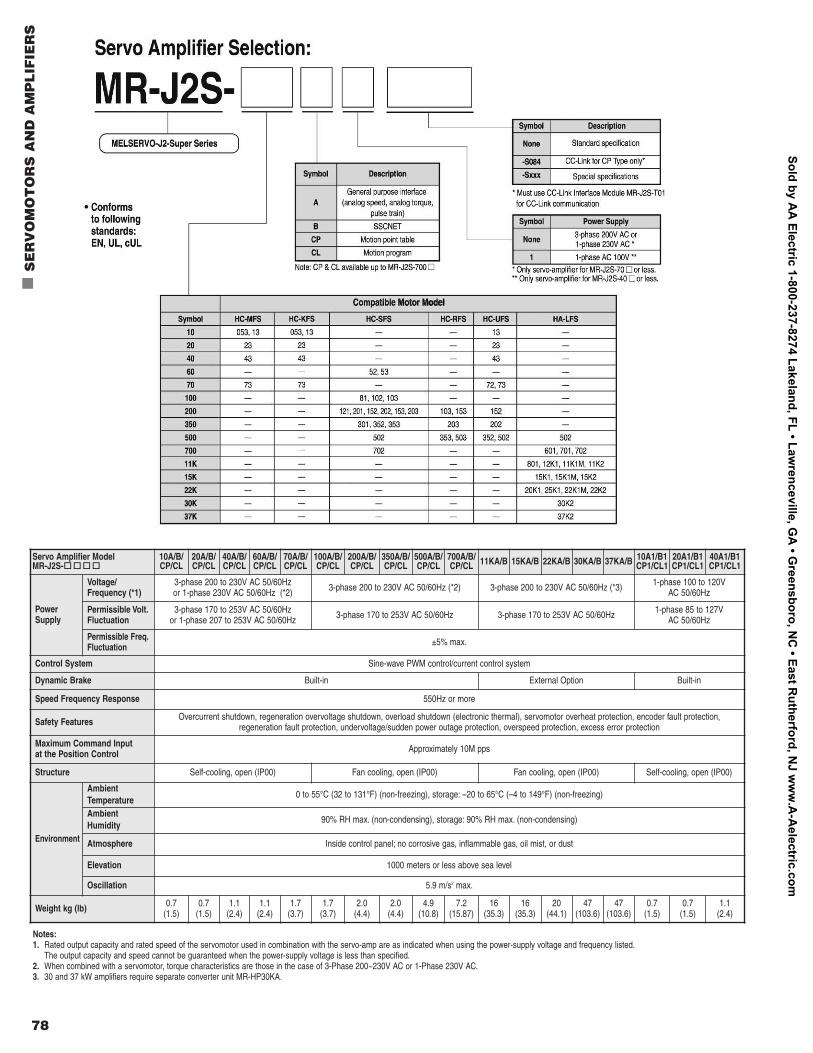
Notes:1. Rated output capacity and rated speed of the servomotor used in combination with the servo-amp are as indicated when using the power-supply voltage and frequency listed.
The output capacity and speed cannot be guaranteed when the power-supply voltage is less than specified.2. When combined with a servomotor, torque characteristics are those in the case of 3-Phase 200~230V AC or 1-Phase 230V AC.3. 30 and 37 kW amplifiers require separate converter unit MR-HP30KA.
Servo Amplifier Model MR-J2S-oooo
10A/B/CP/CL
20A/B/CP/CL
40A/B/CP/CL
60A/B/CP/CL
70A/B/CP/CL
100A/B/CP/CL
200A/B/CP/CL
350A/B/CP/CL
500A/B/ CP/CL
700A/B/ CP/CL 11KA/B 15KA/B 22KA/B 30KA/B 37KA/B 10A1/B1
CP1/CL120A1/B1CP1/CL1
40A1/B1CP1/CL1
Power Supply
Voltage/Frequency (*1)
3-phase 200 to 230V AC 50/60Hzor 1-phase 230V AC 50/60Hz (*2) 3-phase 200 to 230V AC 50/60Hz (*2) 3-phase 200 to 230V AC 50/60Hz (*3) 1-phase 100 to 120V
AC 50/60Hz
Permissible Volt.Fluctuation
3-phase 170 to 253V AC 50/60Hzor 1-phase 207 to 253V AC 50/60Hz 3-phase 170 to 253V AC 50/60Hz 3-phase 170 to 253V AC 50/60Hz 1-phase 85 to 127V
AC 50/60Hz
Permissible Freq.Fluctuation ±5% max.
Control System Sine-wave PWM control/current control system
Dynamic Brake Built-in External Option Built-in
Speed Frequency Response 550Hz or more
Safety Features Overcurrent shutdown, regeneration overvoltage shutdown, overload shutdown (electronic thermal), servomotor overheat protection, encoder fault protection, regeneration fault protection, undervoltage/sudden power outage protection, overspeed protection, excess error protection
Maximum Command Input at the Position Control Approximately 10M pps
Structure Self-cooling, open (IP00) Fan cooling, open (IP00) Fan cooling, open (IP00) Self-cooling, open (IP00)
Environment
Ambient Temperature
0 to 55°C (32 to 131°F) (non-freezing), storage: –20 to 65°C (–4 to 149°F) (non-freezing)
Ambient Humidity
90% RH max. (non-condensing), storage: 90% RH max. (non-condensing)
Atmosphere Inside control panel; no corrosive gas, inflammable gas, oil mist, or dust
Elevation 1000 meters or less above sea level
Oscillation 5.9 m/s2 max.
Weight kg (lb) 0.7(1.5)
0.7(1.5)
1.1(2.4)
1.1(2.4)
1.7(3.7)
1.7(3.7)
2.0(4.4)
2.0(4.4)
4.9(10.8)
7.2(15.87)
16(35.3)
16(35.3)
20(44.1)
47(103.6)
47(103.6)
0.7(1.5)
0.7(1.5)
1.1(2.4)
Sold by AA
Electric 1-800-237-8274 Lakeland, FL • Lawrenceville, G
A • G
reensboro, NC
• East Rutherford, N
J ww
w.A
-Aelectric.com
Mitsubishi Electric Automation | Servomotors and Amplifiers 79
••Inserters ••Mounters
••Conveyormachines
••Robots••X-Y tables
••Ultra-high-frequency
conveyor machines
••Robots ••Food processing
machines
••Injection molding machines••Semiconductor
manufacturingdevices
••Large conveyormachines
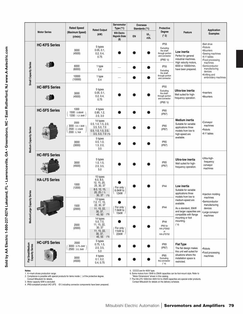
Notes:1. A • mark shows production range.2. Compliance is possible with special products for items inside ( ) of the protective degree.
Consult Mitsubishi for details.3. Motor capacity 50W is excluded.4. IP65-compliant product (HC-UFSo -S1) including connector components have been prepared.
5. are for 400V type.6. Some motors from 15kW to 25kW capacities can be foot-mount style. Refer to
“Motor Dimensions” shown in this catalog.7. The HA-LFS 1000r/min 400V 8.0 to 25kW capacities are special-order products.
Contact Mitsubishi for details on the delivery schedule.
Motor SeriesRated Output
(kW)
Rated Speed(Maximum Speed)
(r/min)
ApplicationExamplesFeature
ProtectiveDegree
(* 2)
HC-KFS Series
HC-MFS Series
HC-SFS Series
HC-RFS Series
HA-LFS Series
HC-UFS Series
OverseasStandards (*1)
With Electro-Magnetic Brake
(B)
ServomotorType (*1)
ENUL, cUL
Low inertiaPerfect for general industrial machines.High velocity motors, 6000 or 10000r/min, have been prepared.
Ultra-low inertiaWell suited for high-frequency operation.
Medium inertiaSuitable for variable applications three models from low to high-speed are available.
Ultra-low inertiaWell suited for high-frequency operation.
Flat TypeThe flat design makes this unit well suited for situations where the installation space is restricted.
Low inertiaSuitable for variable applications three models from low to medium-speed are available.
As a standard, 30kW and larger capacities are compatible with flange mounting or foot mounting. (* 6)
IP55Excludingthe shaft-
through portionand connector
(IP65 *3)
IP55Excludingthe shaft-
through portionand connector
IP55Excludingthe shaft-
through portionand connector
(IP65 *3)
5 types0.05, 0.1,0.2, 0.4,
0.75
3000(4500)
5 types0.05, 0.1,0.2, 0.4,
0.75
3000(4500)
3000(3000)
IP65(IP67)
4 types0.85, 1.2,2.0, 3.0
1000 1500 : 0.85kW 1200 : 1.2~3kW
IP65(IP67)
5 types0.75, 1.5,2.0, 3.5,
5.0
2000 3000 : 0.75~2kW 2500 : 3.5, 5kW
IP65Excluding
the connector(* 4)
4 types0.1, 0.2,0.4, 0.75
2000 3000 : 0.5~1.5kW 2500 : 2, 3.5kW 2000 : 5, 7kW
IP65(IP67)
14 types0.5, 1.0, 1.5, 2.0,
3.5, 5.0, 7.00.5, 1.0, 1.5, 2.0,
3.5, 5.0, 7.0
IP65(IP67)
5 types0.5, 1.0,1.5, 2.0,
3.5
1000(1200) For only
6.0kW to12kW
IP44
For only7.0kW to
15kW
15 types6.0, 8.0,
12, 15, 20, 25, 30, 378.0, 12, 15,20, 25 (* 7)
30, 37
1500(2000) IP44
13 types7.0, 11, 15, 22, 30, 3711, 15, 22,
30, 37,45, 50
For only11kW to22kW
2000(2000)
3000(4500)
IP44IP65 for
HA-LFS502or
HA-LFS702
14 types5.0, 7.0,
11, 15, 22, 30, 37
11, 15, 22,30, 37,45, 55
3000(4500)
IP65(IP67)
5 types1.0, 1.5,2.0, 3.5,
5.0
6000(6000)
10000(10000)
1 type0.4
1 type0.4
Smal
l Cap
acity
Ser
ies
Med
ium
Cap
acity
Ser
ies
Med
ium
/Lar
ge C
apac
ity S
erie
sFl
at S
mal
l/Med
ium
Capa
city
Ser
ies
( )
( )
( )
( )
( )
( )
••Belt drive ••Robots ••Mounters ••Sewing machines ••X-Y tables ••Food processing
machines ••Semiconductor
manufacturing devices
••Knitting and embroidery machines
(*5)
(*5)
(*5)
(*5)
Sold
by
AA
Ele
ctric
1-8
00-2
37-8
274
Lake
land
, FL
• Law
renc
evill
e, G
A •
Gre
ensb
oro,
NC
• Ea
st R
uthe
rfor
d, N
J w
ww
.A-A
elec
tric
.com
80
n
SE
RV
OM
OT
OR
S A
ND
AM
PL
IFIE
RS
Sold by AA
Electric 1-800-237-8274 Lakeland, FL • Lawrenceville, G
A • G
reensboro, NC
• East Rutherford, N
J ww
w.A
-Aelectric.com
Mitsubishi Electric Automation | Servomotors and Amplifiers 81
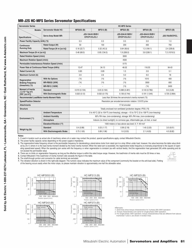
Servomotor Series HC-MFS Series
Servomotor Model HC- MFS053 (B) MFS13 (B) MFS23 (B) MFS43 (B) MFS73 (B)
Servo-Amp Model MR-J2S-10A/A1/B/B1/ J2S-20A/A1/B/B1/ J2S-40A/A1/B/B1/
J2S-70A/B/CP/CLCP/CP1/CL/CL1 CP/CP1/CL/CL1 CP/CP1/CL/CL1
Power Facility Capacity (kVA) (*2) 0.3 0.3 0.5 0.9 1.3
Rated Output (W) 50 100 200 400 750
Rated Torque (N.m [oz.in]) 0.16 (22.7) 0.32 (45.3) 0.64 (90.6) 1.3 (184.1) 2.4 (339.8)
Maximum Torque (N.m [oz.in]) 0.48 (68.0) 0.95 (134.5) 1.9 (269.0) 3.8 (538.1) 7.2 (1019.5)
Rated Rotation Speed (r/min) 3000
Maximum Rotation Speed (r/min) 4500
Permissible Instantaneous Rotation Speed (r/min) 5175
Power Rate at Continuous Rated Torque (kW/s) 13.47 34.13 46.02 116.55 94.43
Rated Current (A) 0.85 0.85 1.5 2.8 5.1
Maximum Current (A) 2.6 2.6 5.0 9.0 18
With No Options (*4) (*4) (*4) 1010 400
MR-RB032 (30W) (*4) (*4) (*4) 3000 600
MR-RB12 (100W) – – (*4) (*4) 2400
Standard 0.019 (0.104) 0.03 (0.164) 0.088 (0.481) 0.143 (0.782) 0.6 (3.28)
With Electromagnetic Brake 0.022 (0.12) 0.032 (0.175) 0.136 (0.744) 0.191 (1.044) 0.725 (3.964)
Recommended Load/Motor Inertia Moment Ratio Less than 30-times the servomotor’s inertia moment (*5)
Speed/Position Detector Resolution per encoder/servomotor rotation: 131072 p/rev
Attachments 17 bit encoder
Structure Totally enclosed non-ventilated (protection degree: IP55) (*6)
Ambient Temperature 0 to 40°C (32 to 104°F) (non-freezing), storage: −15 to 70°C (5 to 158°F) (non-freezing)
Ambient Humidity 80% RH max. (non-condensing), storage: 90% RH max. (non-condensing)
Atmosphere Indoors (no direct sunlight); no corrosive gas, inflammable gas, oil mist, or dust
Elevation/Vibration (*7) 1000 meters or less above sea level; X, Y: 49 m/s2
Weight kg (lb)Standard 0.4 (0.88) 0.53 (1.17) 0.99 (2.18) 1.45 (3.20) 3.0 (6.61)
With Electromagnetic Brake 0.75 (1.65) 0.89 (1.96) 1.6 (3.53) 2.1 (4.63) 4.0 (8.82)
Regeneration Braking Frequency(times/min) (*3)
Moment of Inertia J (××10-4 kg.m2) [WK2 (oz.in2)]
Continuous Running Duty
Specifications
Models
0
28
56
84
0
0.2
0.4
0.6
0
140
280
420
560
0
1.0
2.0
3.0
4.0
0
280
560
840
1120
0
2.0
4.0
6.0
8.0
HC-MFS053 (B)
HC-MFS43 (B) HC-MFS73 (B)
0
35
70
105
140
0
0.25
0.5
0.75
1.0HC-MFS13 (B)
0
70
140
210
280
0
0.5
1.0
1.5
2.0
1000 2000 3000 4000 4500
HC-MFS23 (B)
Torq
ue (o
z•in
)
Rotation speed (r/min)
Torq
ue (o
z•in
)
Rotation speed (r/min)
Torq
ue (o
z•in
)
Rotation speed (r/min)
Torq
ue (o
z•in
)
Rotation speed (r/min)
Torq
ue (o
z•in
)
Rotation speed (r/min)
Torq
ue (N
• m)
Torq
ue (N
• m)
Torq
ue (N
• m)
Torq
ue (N
• m)
Torq
ue (N
• m)
1000 2000 3000 4000 45001000 2000 3000 4000 4500
1000 2000 3000 4000 4500 1000 2000 3000 4000 4500
Peak running range
Continuous running range
Peak running range
Continuous running range
Peak running range
Continuous running range
Peak running range
Continuous running range
Peak running range
Continuous running range
Remarks: 1. Solid lines show torque characteristics for 3-phase 200-230V operation. 2. Torque characteristics are same for single-phase 230V operation. 3. For single-phase 100V operation, torque characteristics that are different from above-
mentioned 1 and 2, are shown in broken lines.
Environment (*1)
Notes:1. If used in location such as actual site of machinery where oil or water may contact the product, special specifications apply, contact Mitsubishi Electric.2. The power facility capacity varies depending on the power supply's impedance.3. The regenerative brake frequency shown is the permissible frequency for decelerating a stand-alone motor from rated rpm to a stop. When under load, however, the value becomes the table value divid-
ed by (m+1) where m is the load inertia moment divided by the motor inertia moment. When the rated rpm is exceeded, the regenerative brake frequency is inversely proportional to the square of (oper-ating speed/rated speed). When the operating rpm varies with the frequency or when regeneration is constant (as with vertical feeds), find the regeneration heat generated (W) while operating and donot exceed the permissible value.
4. There are no limits on regeneration frequency as long as the effective torque is within the rated torque range. However, the load/motor of inertia ratio must be 30 times or less.5. Contact Mitsubishi if the load/motor of inertia moment ratio exceeds the figure in the table.6. The shaft-through portion and connector for cable terminal are excluded.7. The vibration direction is shown in the right-side diagram. The numeric value indicates the maximum value of the component (commonly the bracket on the anti-load side). Fretting
of the bearing occurs easily when the motor stops, so please maintain vibration to approximately one-half the allowable value.
XY
MR-J2S HC-MFS Series Servomotor Specifications
Sold
by
AA
Ele
ctric
1-8
00-2
37-8
274
Lake
land
, FL
• Law
renc
evill
e, G
A •
Gre
ensb
oro,
NC
• Ea
st R
uthe
rfor
d, N
J w
ww
.A-A
elec
tric
.com
82
n
SE
RV
OM
OT
OR
S A
ND
AM
PL
IFIE
RS
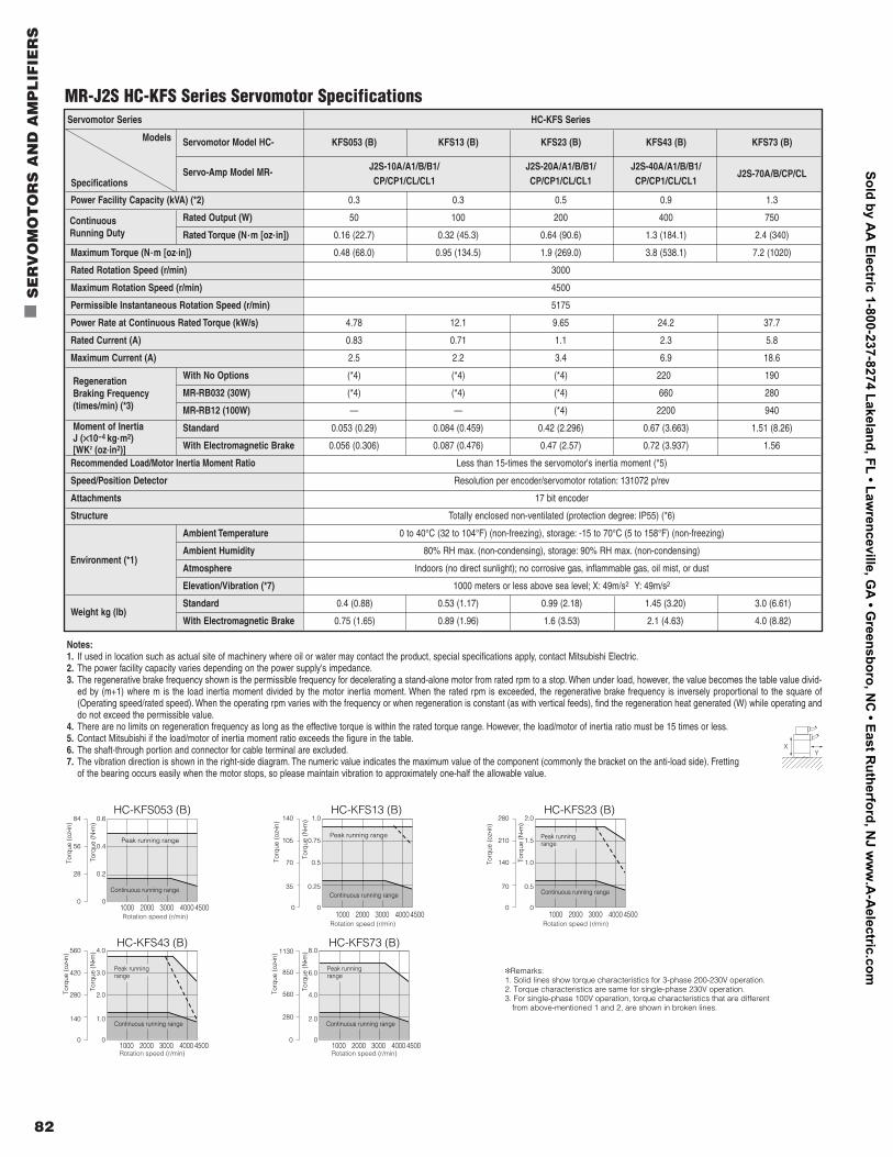
Notes:1. If used in location such as actual site of machinery where oil or water may contact the product, special specifications apply, contact Mitsubishi Electric.2. The power facility capacity varies depending on the power supply's impedance.3. The regenerative brake frequency shown is the permissible frequency for decelerating a stand-alone motor from rated rpm to a stop. When under load, however, the value becomes the table value divid-
ed by (m+1) where m is the load inertia moment divided by the motor inertia moment. When the rated rpm is exceeded, the regenerative brake frequency is inversely proportional to the square of(Operating speed/rated speed). When the operating rpm varies with the frequency or when regeneration is constant (as with vertical feeds), find the regeneration heat generated (W) while operating anddo not exceed the permissible value.
4. There are no limits on regeneration frequency as long as the effective torque is within the rated torque range. However, the load/motor of inertia ratio must be 15 times or less.5. Contact Mitsubishi if the load/motor of inertia moment ratio exceeds the figure in the table.6. The shaft-through portion and connector for cable terminal are excluded.7. The vibration direction is shown in the right-side diagram. The numeric value indicates the maximum value of the component (commonly the bracket on the anti-load side). Fretting
of the bearing occurs easily when the motor stops, so please maintain vibration to approximately one-half the allowable value.
Servomotor Series HC-KFS Series
Servomotor Model HC- KFS053 (B) KFS13 (B) KFS23 (B) KFS43 (B) KFS73 (B)
Servo-Amp Model MR- J2S-10A/A1/B/B1/ J2S-20A/A1/B/B1/ J2S-40A/A1/B/B1/J2S-70A/B/CP/CL
CP/CP1/CL/CL1 CP/CP1/CL/CL1 CP/CP1/CL/CL1
Power Facility Capacity (kVA) (*2) 0.3 0.3 0.5 0.9 1.3
Rated Output (W) 50 100 200 400 750
Rated Torque (N.m [oz.in]) 0.16 (22.7) 0.32 (45.3) 0.64 (90.6) 1.3 (184.1) 2.4 (340)
Maximum Torque (N.m [oz.in]) 0.48 (68.0) 0.95 (134.5) 1.9 (269.0) 3.8 (538.1) 7.2 (1020)
Rated Rotation Speed (r/min) 3000
Maximum Rotation Speed (r/min) 4500
Permissible Instantaneous Rotation Speed (r/min) 5175
Power Rate at Continuous Rated Torque (kW/s) 4.78 12.1 9.65 24.2 37.7
Rated Current (A) 0.83 0.71 1.1 2.3 5.8
Maximum Current (A) 2.5 2.2 3.4 6.9 18.6
With No Options (*4) (*4) (*4) 220 190
MR-RB032 (30W) (*4) (*4) (*4) 660 280
MR-RB12 (100W) — — (*4) 2200 940
Standard 0.053 (0.29) 0.084 (0.459) 0.42 (2.296) 0.67 (3.663) 1.51 (8.26)
With Electromagnetic Brake 0.056 (0.306) 0.087 (0.476) 0.47 (2.57) 0.72 (3.937) 1.56
Recommended Load/Motor Inertia Moment Ratio Less than 15-times the servomotor's inertia moment (*5)
Speed/Position Detector Resolution per encoder/servomotor rotation: 131072 p/rev
Attachments 17 bit encoder
Structure Totally enclosed non-ventilated (protection degree: IP55) (*6)
Ambient Temperature 0 to 40°C (32 to 104°F) (non-freezing), storage: -15 to 70°C (5 to 158°F) (non-freezing)
Ambient Humidity 80% RH max. (non-condensing), storage: 90% RH max. (non-condensing)
Atmosphere Indoors (no direct sunlight); no corrosive gas, inflammable gas, oil mist, or dust
Elevation/Vibration (*7) 1000 meters or less above sea level; X: 49m/s2 Y: 49m/s2
Weight kg (lb)Standard 0.4 (0.88) 0.53 (1.17) 0.99 (2.18) 1.45 (3.20) 3.0 (6.61)
With Electromagnetic Brake 0.75 (1.65) 0.89 (1.96) 1.6 (3.53) 2.1 (4.63) 4.0 (8.82)
Regeneration Braking Frequency(times/min) (*3)
Moment of InertiaJ (××10-4 kg.m2) [WK2 (oz.in2)]
Continuous Running Duty
Specifications
Models
0
28
56
84
0
0.2
0.4
0.6
0
140
280
420
560
0
1.0
2.0
3.0
4.0
HC-KFS053 (B)
HC-KFS43 (B)
0
35
70
105
140
0
0.25
0.5
0.75
1.0HC-KFS13 (B)
0
70
140
210
280
0
0.5
1.0
1.5
2.0
1000 2000 3000 4000 4500
HC-KFS23 (B)
Torq
ue (o
z•in
)
Rotation speed (r/min)
Torq
ue (o
z•in
)
Rotation speed (r/min)
Torq
ue (o
z•in
)
Rotation speed (r/min)
Torq
ue (o
z•in
)
Rotation speed (r/min)
Torq
ue (N
• m)
Torq
ue (N
• m)
Torq
ue (N
• m)
Torq
ue (N
• m)
1000 2000 3000 4000 45001000 2000 3000 4000 4500
1000 2000 3000 4000 4500
Peak running rangePeak running range
Continuous running rangeContinuous running range
Peak running range
Continuous running range
Peak running range
Continuous running range
0
0
2.0
4.0
6.0
8.0HC-KFS73 (B)
Torq
ue (o
z•in
)
Rotation speed (r/min)
Torq
ue (N
• m)
1000 2000 3000 4000 4500
Peak running range
Continuous running range
Remarks: 1. Solid lines show torque characteristics for 3-phase 200-230V operation. 2. Torque characteristics are same for single-phase 230V operation. 3. For single-phase 100V operation, torque characteristics that are different
from above-mentioned 1 and 2, are shown in broken lines.280
560
850
1130
Environment (*1)
XY
MR-J2S HC-KFS Series Servomotor Specifications
Sold by AA
Electric 1-800-237-8274 Lakeland, FL • Lawrenceville, G
A • G
reensboro, NC
• East Rutherford, N
J ww
w.A
-Aelectric.com
Mitsubishi Electric Automation | Servomotors and Amplifiers 83
4200
500 1000 1500
2800
1400
0
30
20
10
0
HC-SFS81 (B)
Rotation speed (r/min)
Torq
ue (o
z•in
)
Torq
ue (N
• m) 5600
500 1000 1200
4200
1400
2800
0
40
30
20
10
0
HC-SFS121 (B)
Rotation speed (r/min)
Torq
ue (o
z•in
)
Torq
ue (N
• m) 8400
500 1000 1200
5600
2800
0
60
40
20
0
HC-SFS201 (B)
Rotation speed (r/min)
Torq
ue (o
z•in
)
Torq
ue (N
• m) 14000
500 1000 1200
10500
7000
3500
0
100
75
50
25
0
HC-SFS301 (B)
Rotation speed (r/min)
Torq
ue (o
z•in
)
Torq
ue (N
• m)
1260
1000 2000 3000
840
420
0
9
6
3
0
HC-SFS52 (B)
Rotation speed (r/min)
Torq
ue (o
z•in
)
Torq
ue (N
• m) 2100
1000 2000 3000
1400
700
0
15
10
5
0
HC-SFS102 (B)
Rotation speed (r/min)
Torq
ue (o
z•in
)
Torq
ue (N
• m) 3360
1000 2000 3000
2240
1120
0
24
16
8
0
HC-SFS152 (B)
Rotation speed (r/min)
Torq
ue (o
z•in
)
Torq
ue (N
• m)
4200
1000 2000 2500
2800
1400
0
30
20
10
0
HC-SFS202 (B)
Rotation speed (r/min)
Torq
ue (o
z•in
)
Torq
ue (N
• m)
840
1000 2000 3000
560
280
0
6
4
2
0
HC-SFS53 (B)
Rotation speed (r/min)
Torq
ue (o
z•in
)
Torq
ue (N
• m)
8400
1000 2000 2500
5600
2800
0
60
40
20
0
HC-SFS352 (B)
Rotation speed (r/min)
Torq
ue (o
z•in
)
Torq
ue (N
• m)
1680
1000 2000 3000
1120
560
0
12
8
4
0
HC-SFS103 (B)
Rotation speed (r/min)
Torq
ue (o
z•in
)
Torq
ue (N
• m) 2100
1000 2000 3000
1400
700
0
15
10
5
0
HC-SFS153 (B)
Rotation speed (r/min)
Torq
ue (o
z•in
)
Torq
ue (N
• m)
2940
1000 2000 3000
1960
980
0
21
14
7
0
HC-SFS203 (B)
Rotation speed (r/min)
Torq
ue (o
z•in
)
Torq
ue (N
• m) 5460
1000 2000 3000
3640
1820
0
39
26
13
0
HC-SFS353 (B)
Rotation speed (r/min)
Torq
ue (o
z•in
)
Torq
ue (N
• m)
Peak running range
Continuous running range
Peak running range
Continuous running range
16800
1000 2000
11200
5600
0
120
80
40
0
HC-SFS702 (B)
Rotation speed (r/min)
Torq
ue (o
z•in
)
Torq
ue (N
• m)11200
1000 2000
8400
5600
2800
0
80
60
20
40
0
HC-SFS502 (B)
Rotation speed (r/min)
Torq
ue (o
z•in
)
Torq
ue (N
• m)
Peak running range
Continuous running range
Peak running range
Continuous running range
Peak running range
Continuous running range
Peak running range
Continuous running range
Peak running range
Continuous running range
Peak running range
Continuous running range
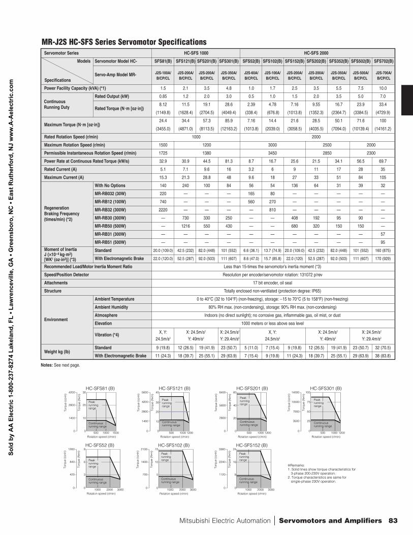
Remarks: 1. Solid lines show torque characteristics for
3-phase 200-230V operation. 2. Torque characteristics are same for
single-phase 230V operation.
MR-J2S HC-SFS Series Servomotor SpecificationsServomotor Series HC-SFS 1000 HC-SFS 2000
Servomotor Model HC- SFS81(B) SFS121(B) SFS201(B) SFS301(B) SFS52(B) SFS102(B) SFS152(B) SFS202(B) SFS352(B) SFS502(B) SFS702(B)
J2S-100A/ J2S-200A/ J2S-200A/ J2S-350A/ J2S-60A/ J2S-100A/ J2S-200A/ J2S-200A/ J2S-350A/ J2S-500A/ J2S-700A/Servo-Amp Model MR-B/CP/CL B/CP/CL B/CP/CL B/CP/CL B/CP/CL B/CP/CL B/CP/CL B/CP/CL B/CP/CL B/CP/CL B/CP/CL
Power Facility Capacity (kVA) (*1) 1.5 2.1 3.5 4.8 1.0 1.7 2.5 3.5 5.5 7.5 10.0
Rated Output (kW) 0.85 1.2 2.0 3.0 0.5 1.0 1.5 2.0 3.5 5.0 7.0
Rated Torque (N.m [oz.in])8.12 11.5 19.1 28.6 2.39 4.78 7.16 9.55 16.7 23.9 33.4
(1149.8) (1628.4) (2704.5) (4049.4) (338.4) (676.8) (1013.8) (1352.3) (2364.7) (3384.5) (4729.9)
Maximum Torque (N.m [oz.in])24.4 34.4 57.3 85.9 7.16 14.4 21.6 28.5 50.1 71.6 100
(3455.0) (4871.0) (8113.5) (12163.2) (1013.8) (2039.0) (3058.5) (4035.5) (7094.0) (10139.4) (14161.2)
Rated Rotation Speed (r/min) 1000 2000
Maximum Rotation Speed (r/min) 1500 1200 3000 2500 2000
Permissible Instantaneous Rotation Speed (r/min) 1725 1380 3450 2850 2300
Power Rate at Continuous Rated Torque (kW/s) 32.9 30.9 44.5 81.3 8.7 16.7 25.6 21.5 34.1 56.5 69.7
Rated Current (A) 5.1 7.1 9.6 16 3.2 6 9 11 17 28 35
Maximum Current (A) 15.3 21.3 28.8 48 9.6 18 27 33 51 84 105
With No Options 140 240 100 84 56 54 136 64 31 39 32
MR-RB032 (30W) 220 — — — 165 80 — — — — —
MR-RB12 (100W) 740 — — — 560 270 — — — — —
MR-RB32 (300W) 2220 — — — — 810 — — — — —
MR-RB30 (300W) — 730 330 250 — — 408 192 95 90 —
MR-RB50 (500W) — 1216 550 430 — — 680 320 150 150 —
MR-RB31 (300W) — — — — — — — — — — 57
MR-RB51 (500W) — — — — — — — — — — 95
Standard 20.0 (109.0) 42.5 (232) 82.0 (448) 101 (552) 6.6 (36.1) 13.7 (74.9) 20.0 (109.0) 42.5 (232) 82.0 (448) 101 (552) 160 (875)
With Electromagnetic Brake 22.0 (120.0) 52.5 (287) 92.0 (503) 111 (607) 8.6 (47.0) 15.7 (85.8) 22.0 (120) 52.5 (287) 92.0 (503) 111 (607) 170 (929)
Recommended Load/Motor Inertia Moment Ratio Less than 15-times the servomotor’s inertia moment (*3)
Speed/Position Detector Resolution per encoder/servomotor rotation: 131072 p/rev
Attachments 17 bit encoder, oil seal
Structure Totally enclosed non-ventilated (protection degree: IP65)
Ambient Temperature 0 to 40°C (32 to 104°F) (non-freezing), storage: −15 to 70°C (5 to 158°F) (non-freezing)
Ambient Humidity 80% RH max. (non-condensing), storage: 90% RH max. (non-condensing)
Atmosphere Indoors (no direct sunlight); no corrosive gas, inflammable gas, oil mist, or dust
Elevation 1000 meters or less above sea level
Vibration (*4) X, Y: X: 24.5m/s2 X: 24.5m/s2 X, Y: X: 24.5m/s2 X: 24.5m/s2
24.5m/s2 Y: 49m/s2 Y: 29.4m/s2 24.5m/s2 Y: 49m/s2 Y: 29.4m/s2
Weight kg (lb)Standard 9 (19.8) 12 (26.5) 19 (41.9) 23 (50.7) 5 (11.0) 7 (15.4) 9 (19.8) 12 (26.5) 19 (41.9) 23 (50.7) 32 (70.5)
With Electromagnetic Brake 11 (24.3) 18 (39.7) 25 (55.1) 29 (63.9) 7 (15.4) 9 (19.8) 11 (24.3) 18 (39.7) 25 (55.1) 29 (63.9) 38 (83.8)
Regeneration Braking Frequency(times/min) (*2)
Moment of InertiaJ (××10-4 kg.m2) [WK2 (oz.in2)] (*3)
Continuous Running Duty
Specifications
Models
Environment
Notes: See next page.
Sold
by
AA
Ele
ctric
1-8
00-2
37-8
274
Lake
land
, FL
• Law
renc
evill
e, G
A •
Gre
ensb
oro,
NC
• Ea
st R
uthe
rfor
d, N
J w
ww
.A-A
elec
tric
.com
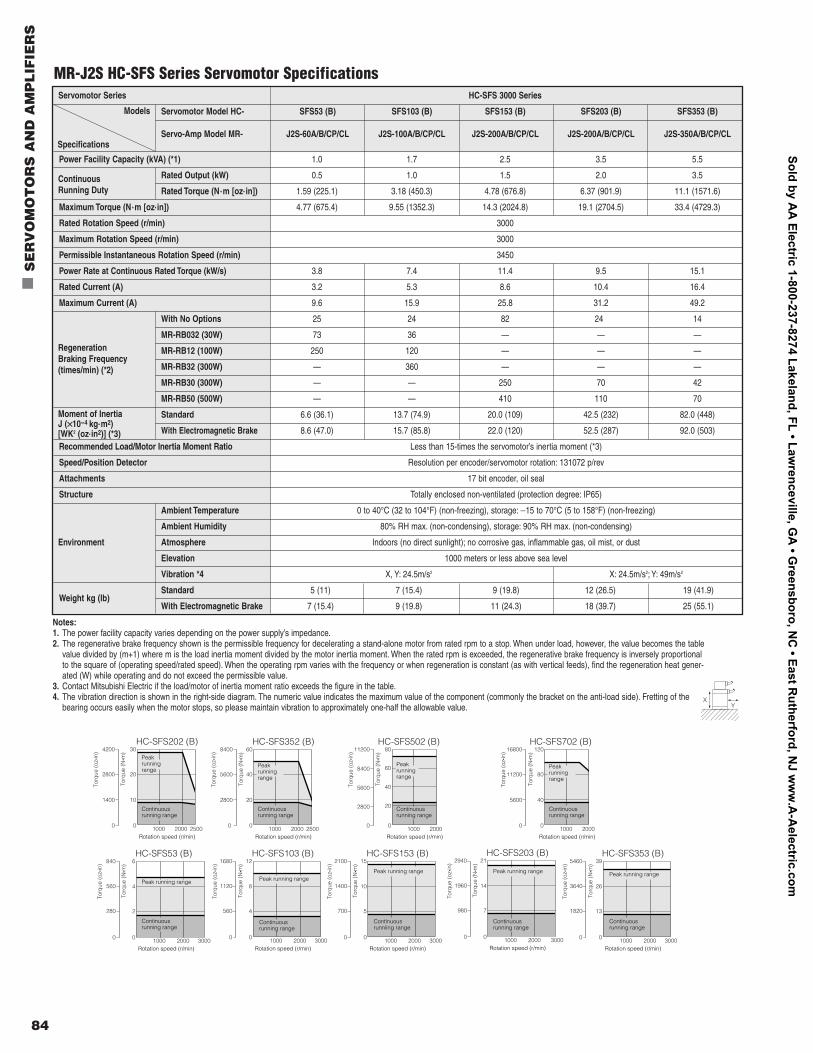
84
n
SE
RV
OM
OT
OR
S A
ND
AM
PL
IFIE
RS
4200
500 1000 1500
2800
1400
0
30
20
10
0
HC-SFS81 (B)
Rotation speed (r/min)
Torq
ue (o
z•in
)
Torq
ue (N
• m) 5600
500 1000 1200
4200
1400
2800
0
40
30
20
10
0
HC-SFS121 (B)
Rotation speed (r/min)
Torq
ue (o
z•in
)
Torq
ue (N
• m) 8400
500 1000 1200
5600
2800
0
60
40
20
0
HC-SFS201 (B)
Rotation speed (r/min)
Torq
ue (o
z•in
)
Torq
ue (N
• m) 14000
500 1000 1200
10500
7000
3500
0
100
75
50
25
0
HC-SFS301 (B)
Rotation speed (r/min)
Torq
ue (o
z•in
)
Torq
ue (N
• m)
1260
1000 2000 3000
840
420
0
9
6
3
0
HC-SFS52 (B)
Rotation speed (r/min)
Torq
ue (o
z•in
)
Torq
ue (N
• m) 2100
1000 2000 3000
1400
700
0
15
10
5
0
HC-SFS102 (B)
Rotation speed (r/min)
Torq
ue (o
z•in
)
Torq
ue (N
• m) 3360
1000 2000 3000
2240
1120
0
24
16
8
0
HC-SFS152 (B)
Rotation speed (r/min)
Torq
ue (o
z•in
)
Torq
ue (N
• m)
4200
1000 2000 2500
2800
1400
0
30
20
10
0
HC-SFS202 (B)
Rotation speed (r/min)
Torq
ue (o
z•in
)
Torq
ue (N
• m)
840
1000 2000 3000
560
280
0
6
4
2
0
HC-SFS53 (B)
Rotation speed (r/min)
Torq
ue (o
z•in
)
Torq
ue (N
• m)
8400
1000 2000 2500
5600
2800
0
60
40
20
0
HC-SFS352 (B)
Rotation speed (r/min)
Torq
ue (o
z•in
)
Torq
ue (N
• m)
1680
1000 2000 3000
1120
560
0
12
8
4
0
HC-SFS103 (B)
Rotation speed (r/min)
Torq
ue (o
z•in
)
Torq
ue (N
• m) 2100
1000 2000 3000
1400
700
0
15
10
5
0
HC-SFS153 (B)
Rotation speed (r/min)
Torq
ue (o
z•in
)
Torq
ue (N
• m)
2940
1000 2000 3000
1960
980
0
21
14
7
0
HC-SFS203 (B)
Rotation speed (r/min)
Torq
ue (o
z•in
)
Torq
ue (N
• m) 5460
1000 2000 3000
3640
1820
0
39
26
13
0
HC-SFS353 (B)
Rotation speed (r/min)
Torq
ue (o
z•in
)
Torq
ue (N
• m)
Peak running range
Continuous running range
Peak running range
Continuous running range
16800
1000 2000
11200
5600
0
120
80
40
0
HC-SFS702 (B)
Rotation speed (r/min)
Torq
ue (o
z•in
)
Torq
ue (N
• m)11200
1000 2000
8400
5600
2800
0
80
60
20
40
0
HC-SFS502 (B)
Rotation speed (r/min)
Torq
ue (o
z•in
)
Torq
ue (N
• m)
Peak running range
Continuous running range
Peak running range
Continuous running range
Peak running range
Continuous running range
Peak running range
Continuous running range
Peak running range
Continuous runniing range
Peak running range
Continuous running range
Peak running range
Continuous running range
Peak running range
Continuous running range
Remarks: 1. Solid lines show torque characteristics for
3-phase 200-230V operation. 2. Torque characteristics are same for
single-phase 230V operation.
MR-J2S HC-SFS Series Servomotor SpecificationsServomotor Series HC-SFS 3000 Series
Servomotor Model HC- SFS53 (B) SFS103 (B) SFS153 (B) SFS203 (B) SFS353 (B)
Servo-Amp Model MR- J2S-60A/B/CP/CL J2S-100A/B/CP/CL J2S-200A/B/CP/CL J2S-200A/B/CP/CL J2S-350A/B/CP/CL
Power Facility Capacity (kVA) (*1) 1.0 1.7 2.5 3.5 5.5
Rated Output (kW) 0.5 1.0 1.5 2.0 3.5
Rated Torque (N.m [oz.in]) 1.59 (225.1) 3.18 (450.3) 4.78 (676.8) 6.37 (901.9) 11.1 (1571.6)
Maximum Torque (N.m [oz.in]) 4.77 (675.4) 9.55 (1352.3) 14.3 (2024.8) 19.1 (2704.5) 33.4 (4729.3)
Rated Rotation Speed (r/min) 3000
Maximum Rotation Speed (r/min) 3000
Permissible Instantaneous Rotation Speed (r/min) 3450
Power Rate at Continuous Rated Torque (kW/s) 3.8 7.4 11.4 9.5 15.1
Rated Current (A) 3.2 5.3 8.6 10.4 16.4
Maximum Current (A) 9.6 15.9 25.8 31.2 49.2
With No Options 25 24 82 24 14
MR-RB032 (30W) 73 36 — — —
MR-RB12 (100W) 250 120 — — —
MR-RB32 (300W) — 360 — — —
MR-RB30 (300W) — — 250 70 42
MR-RB50 (500W) — — 410 110 70
Standard 6.6 (36.1) 13.7 (74.9) 20.0 (109) 42.5 (232) 82.0 (448)
With Electromagnetic Brake 8.6 (47.0) 15.7 (85.8) 22.0 (120) 52.5 (287) 92.0 (503)
Recommended Load/Motor Inertia Moment Ratio Less than 15-times the servomotor’s inertia moment (*3)
Speed/Position Detector Resolution per encoder/servomotor rotation: 131072 p/rev
Attachments 17 bit encoder, oil seal
Structure Totally enclosed non-ventilated (protection degree: IP65)
Ambient Temperature 0 to 40°C (32 to 104°F) (non-freezing), storage: −15 to 70°C (5 to 158°F) (non-freezing)
Ambient Humidity 80% RH max. (non-condensing), storage: 90% RH max. (non-condensing)
Atmosphere Indoors (no direct sunlight); no corrosive gas, inflammable gas, oil mist, or dust
Elevation 1000 meters or less above sea level
Vibration *4 X, Y: 24.5m/s2 X: 24.5m/s2; Y: 49m/s2
Weight kg (lb)Standard 5 (11) 7 (15.4) 9 (19.8) 12 (26.5) 19 (41.9)
With Electromagnetic Brake 7 (15.4) 9 (19.8) 11 (24.3) 18 (39.7) 25 (55.1)
Regeneration Braking Frequency(times/min) (*2)
Moment of InertiaJ (××10-4 kg.m2) [WK2 (oz.in2)] (*3)
Continuous Running Duty
Specifications
Models
Environment
Notes:1. The power facility capacity varies depending on the power supply’s impedance.2. The regenerative brake frequency shown is the permissible frequency for decelerating a stand-alone motor from rated rpm to a stop. When under load, however, the value becomes the table
value divided by (m+1) where m is the load inertia moment divided by the motor inertia moment. When the rated rpm is exceeded, the regenerative brake frequency is inversely proportionalto the square of (operating speed/rated speed). When the operating rpm varies with the frequency or when regeneration is constant (as with vertical feeds), find the regeneration heat gener-ated (W) while operating and do not exceed the permissible value.
3. Contact Mitsubishi Electric if the load/motor of inertia moment ratio exceeds the figure in the table.4. The vibration direction is shown in the right-side diagram. The numeric value indicates the maximum value of the component (commonly the bracket on the anti-load side). Fretting of the
bearing occurs easily when the motor stops, so please maintain vibration to approximately one-half the allowable value.X
Y
Sold by AA
Electric 1-800-237-8274 Lakeland, FL • Lawrenceville, G
A • G
reensboro, NC
• East Rutherford, N
J ww
w.A
-Aelectric.com
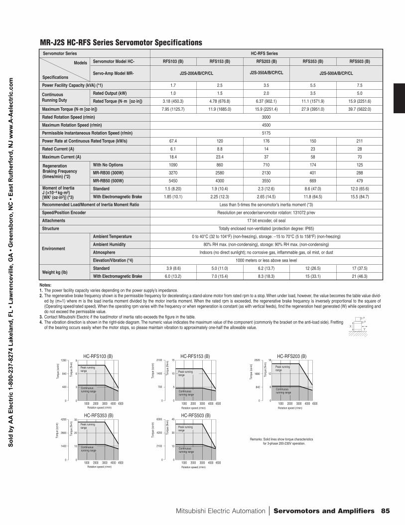
Mitsubishi Electric Automation | Servomotors and Amplifiers 85
Servomotor Series HC-RFS Series
Servomotor Model HC- RFS103 (B) RFS153 (B) RFS203 (B) RFS353 (B) RFS503 (B)
Servo-Amp Model MR- J2S-200A/B/CP/CL J2S-350A/B/CP/CL J2S-500A/B/CP/CL
Power Facility Capacity (kVA) (*1) 1.7 2.5 3.5 5.5 7.5
Rated Output (kW) 1.0 1.5 2.0 3.5 5.0
Rated Torque (N.m [oz.in]) 3.18 (450.3) 4.78 (676.8) 6.37 (902.1) 11.1 (1571.9) 15.9 (2251.6)
Maximum Torque (N.m [oz.in]) 7.95 (1125.7) 11.9 (1685.0) 15.9 (2251.4) 27.9 (3951.0) 39.7 (5622.0)
Rated Rotation Speed (r/min) 3000
Maximum Rotation Speed (r/min) 4500
Permissible Instantaneous Rotation Speed (r/min) 5175
Power Rate at Continuous Rated Torque (kW/s) 67.4 120 176 150 211
Rated Current (A) 6.1 8.8 14 23 28
Maximum Current (A) 18.4 23.4 37 58 70
With No Options 1090 860 710 174 125
MR-RB30 (300W) 3270 2580 2130 401 288
MR-RB50 (500W) 5450 4300 3550 669 479
Standard 1.5 (8.20) 1.9 (10.4) 2.3 (12.6) 8.6 (47.0) 12.0 (65.6)
With Electromagnetic Brake 1.85 (10.1) 2.25 (12.3) 2.65 (14.5) 11.8 (64.5) 15.5 (84.7)
Recommended Load/Moment of Inertia Moment Ratio Less than 5-times the servomotor’s inertia moment (*3)
Speed/Position Encoder Resolution per encoder/servomotor rotation: 131072 p/rev
Attachments 17 bit encoder, oil seal
Structure Totally enclosed non-ventilated (protection degree: IP65)
Ambient Temperature 0 to 40°C (32 to 104°F) (non-freezing), storage: −15 to 70°C (5 to 158°F) (non-freezing)
Ambient Humidity 80% RH max. (non-condensing), storage: 90% RH max. (non-condensing)
Atmosphere Indoors (no direct sunlight); no corrosive gas, inflammable gas, oil mist, or dust
Elevation/Vibration (*4) 1000 meters or less above sea level
Weight kg (lb)Standard 3.9 (8.6) 5.0 (11.0) 6.2 (13.7) 12 (26.5) 17 (37.5)
With Electromagnetic Brake 6.0 (13.2) 7.0 (15.4) 8.3 (18.3) 15 (33.1) 21 (46.3)
Regeneration Braking Frequency(times/min) (*2)
Moment of InertiaJ (××10-4 kg.m2) [WK2 (oz.in2)] (*3)
Continuous Running Duty
Specifications
Models
Notes:1. The power facility capacity varies depending on the power supply’s impedance.2. The regenerative brake frequency shown is the permissible frequency for decelerating a stand-alone motor from rated rpm to a stop. When under load, however, the value becomes the table value divid-
ed by (m+1) where m is the load inertia moment divided by the motor inertia moment. When the rated rpm is exceeded, the regenerative brake frequency is inversely proportional to the square of(Operating speed/rated speed). When the operating rpm varies with the frequency or when regeneration is constant (as with vertical feeds), find the regeneration heat generated (W) while operating anddo not exceed the permissible value.
3. Contact Mitsubishi Electric if the load/motor of inertia ratio exceeds the figure in the table.4. The vibration direction is shown in the right-side diagram. The numeric value indicates the maximum value of the component (commonly the bracket on the anti-load side). Fretting
of the bearing occurs easily when the motor stops, so please maintain vibration to approximately one-half the allowable value.
Environment
XY
0
420
840
1260
0
3
6
9HC-RFS103 (B)
0
700
1400
2100
0
15
10
5
HC-RFS153 (B)
0
840
1680
2520
0
18
12
6
HC-RFS203 (B)
Torq
ue (o
z•in
)
Rotation speed (r/min)
Torq
ue (o
z•in
)
Rotation speed (r/min)
Torq
ue (o
z•in
)
Rotation speed (r/min)
Torq
ue (N
• m)
Torq
ue (N
• m)
Torq
ue (N
• m)
1000 2000 3000 4000 4500 1000 2000 3000 4000 4500 1000 2000 3000 4000 4500
Peak running range
Continuous running range
0
1400
2800
4200
0
10
20
30HC-RFS353 (B)
0
2100
4200
6300
0
45
30
15
HC-RFS503 (B)
Torq
ue (o
z•in
)
Rotation speed (r/min)
Torq
ue (o
z•in
)
Rotation speed (r/min)
Torq
ue (N
• m)
Torq
ue (N
• m)
1000 2000 3000 4000 4500 1000 2000 3000 4000 4500
Peak running range
Continuous running range
Peak running range
Continuous running range
Peak running range
Continuous running range
Peak running range
Continuous running range
Remarks: Solid lines show torque characteristics for 3-phase 200-230V operation.
MR-J2S HC-RFS Series Servomotor Specifications
Sold
by
AA
Ele
ctric
1-8
00-2
37-8
274
Lake
land
, FL
• Law
renc
evill
e, G
A •
Gre
ensb
oro,
NC
• Ea
st R
uthe
rfor
d, N
J w
ww
.A-A
elec
tric
.com
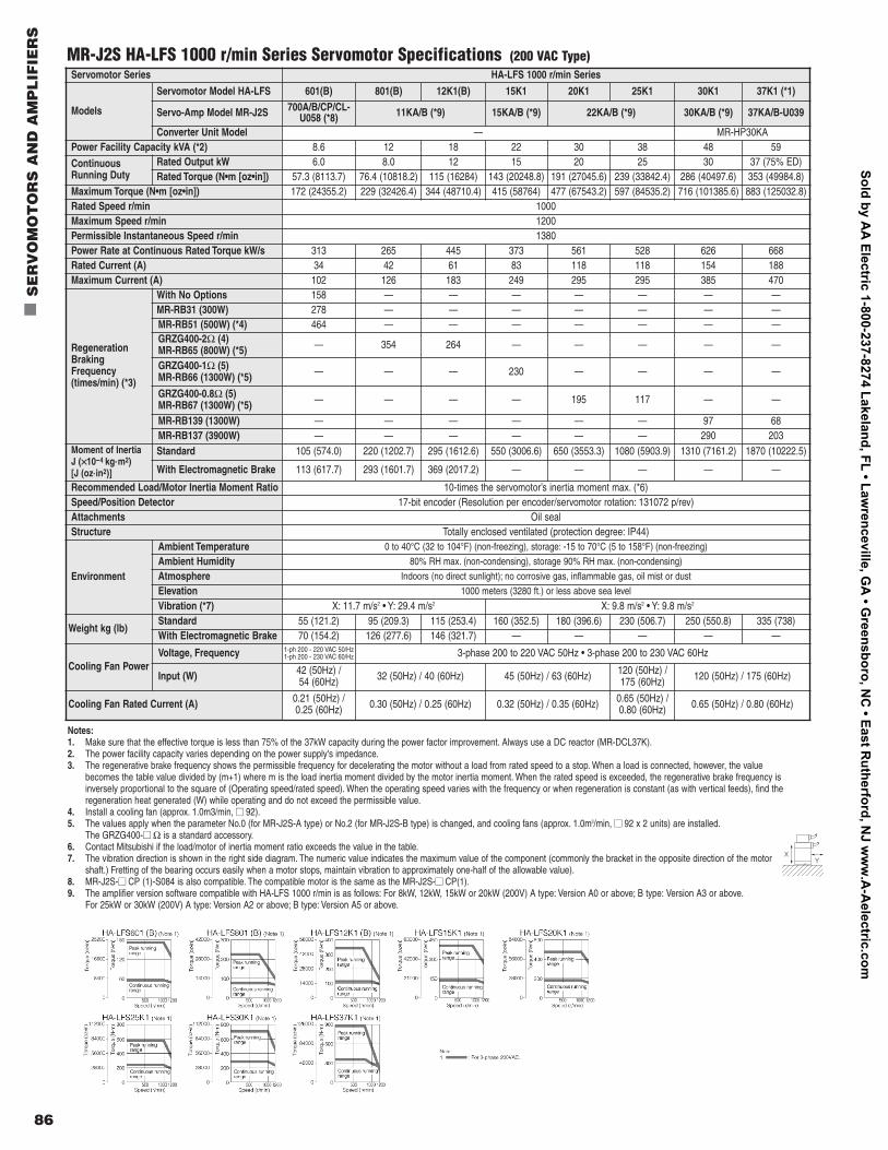
86
n
SE
RV
OM
OT
OR
S A
ND
AM
PL
IFIE
RS
Servomotor Series HA-LFS 1000 r/min Series
Models
Servomotor Model HA-LFS 601(B) 801(B) 12K1(B) 15K1 20K1 25K1 30K1 37K1 (*1)
Servo-Amp Model MR-J2S 700A/B/CP/CL-U058 (*8) 11KA/B (*9) 15KA/B (*9) 22KA/B (*9) 30KA/B (*9) 37KA/B-U039
Converter Unit Model — MR-HP30KAPower Facility Capacity kVA (*2) 8.6 12 18 22 30 38 48 59
ContinuousRunning Duty
Rated Output kW 6.0 8.0 12 15 20 25 30 37 (75% ED)Rated Torque (N•m [oz•in]) 57.3 (8113.7) 76.4 (10818.2) 115 (16284) 143 (20248.8) 191 (27045.6) 239 (33842.4) 286 (40497.6) 353 (49984.8)
Maximum Torque (N•m [oz•in]) 172 (24355.2) 229 (32426.4) 344 (48710.4) 415 (58764) 477 (67543.2) 597 (84535.2) 716 (101385.6) 883 (125032.8)Rated Speed r/min 1000Maximum Speed r/min 1200Permissible Instantaneous Speed r/min 1380Power Rate at Continuous Rated Torque kW/s 313 265 445 373 561 528 626 668Rated Current (A) 34 42 61 83 118 118 154 188Maximum Current (A) 102 126 183 249 295 295 385 470
RegenerationBrakingFrequency(times/min) (*3)
With No Options 158 — — — — — — —MR-RB31 (300W) 278 — — — — — — —MR-RB51 (500W) (*4) 464 — — — — — — —GRZG400-2Ω (4)MR-RB65 (800W) (*5) — 354 264 — — — — —
GRZG400-1Ω (5)MR-RB66 (1300W) (*5) — — — 230 — — — —
GRZG400-0.8Ω (5)MR-RB67 (1300W) (*5) — — — — 195 117 — —
MR-RB139 (1300W) — — — — — — 97 68MR-RB137 (3900W) — — — — — — 290 203
Moment of InertiaJ (××10-4 kg.m2) [J (oz.in2)]
Standard 105 (574.0) 220 (1202.7) 295 (1612.6) 550 (3006.6) 650 (3553.3) 1080 (5903.9) 1310 (7161.2) 1870 (10222.5)
With Electromagnetic Brake 113 (617.7) 293 (1601.7) 369 (2017.2) — — — — —
Recommended Load/Motor Inertia Moment Ratio 10-times the servomotor’s inertia moment max. (*6)Speed/Position Detector 17-bit encoder (Resolution per encoder/servomotor rotation: 131072 p/rev)Attachments Oil sealStructure Totally enclosed ventilated (protection degree: IP44)
Environment
Ambient Temperature 0 to 40°C (32 to 104°F) (non-freezing), storage: -15 to 70°C (5 to 158°F) (non-freezing)
Ambient Humidity 80% RH max. (non-condensing), storage 90% RH max. (non-condensing)
Atmosphere Indoors (no direct sunlight); no corrosive gas, inflammable gas, oil mist or dust
Elevation 1000 meters (3280 ft.) or less above sea level
Vibration (*7) X: 11.7 m/s2 • Y: 29.4 m/s2 X: 9.8 m/s2 • Y: 9.8 m/s2
Weight kg (lb)Standard 55 (121.2) 95 (209.3) 115 (253.4) 160 (352.5) 180 (396.6) 230 (506.7) 250 (550.8) 335 (738)With Electromagnetic Brake 70 (154.2) 126 (277.6) 146 (321.7) — — — — —
Cooling Fan PowerVoltage, Frequency 1-ph 200 - 220 VAC 50/Hz
1-ph 200 - 230 VAC 60/Hz 3-phase 200 to 220 VAC 50Hz • 3-phase 200 to 230 VAC 60Hz
Input (W) 42 (50Hz) / 54 (60Hz) 32 (50Hz) / 40 (60Hz) 45 (50Hz) / 63 (60Hz) 120 (50Hz) /
175 (60Hz) 120 (50Hz) / 175 (60Hz)
Cooling Fan Rated Current (A) 0.21 (50Hz) /0.25 (60Hz) 0.30 (50Hz) / 0.25 (60Hz) 0.32 (50Hz) / 0.35 (60Hz) 0.65 (50Hz) /
0.80 (60Hz) 0.65 (50Hz) / 0.80 (60Hz)
MR-J2S HA-LFS 1000 r/min Series Servomotor Specifications (200 VAC Type)
Notes:1. Make sure that the effective torque is less than 75% of the 37kW capacity during the power factor improvement. Always use a DC reactor (MR-DCL37K).2. The power facility capacity varies depending on the power supply's impedance.3. The regenerative brake frequency shows the permissible frequency for decelerating the motor without a load from rated speed to a stop. When a load is connected, however, the value
becomes the table value divided by (m+1) where m is the load inertia moment divided by the motor inertia moment. When the rated speed is exceeded, the regenerative brake frequency isinversely proportional to the square of (Operating speed/rated speed). When the operating speed varies with the frequency or when regeneration is constant (as with vertical feeds), find theregeneration heat generated (W) while operating and do not exceed the permissible value.
4. Install a cooling fan (approx. 1.0m3/min, nn 92).5. The values apply when the parameter No.0 (for MR-J2S-A type) or No.2 (for MR-J2S-B type) is changed, and cooling fans (approx. 1.0m3/min, nn 92 x 2 units) are installed.
The GRZG400-nn Ω is a standard accessory.6. Contact Mitsubishi if the load/motor of inertia moment ratio exceeds the value in the table.7. The vibration direction is shown in the right side diagram. The numeric value indicates the maximum value of the component (commonly the bracket in the opposite direction of the motor
shaft.) Fretting of the bearing occurs easily when a motor stops, maintain vibration to approximately one-half of the allowable value).8. MR-J2S-nn CP (1)-S084 is also compatible. The compatible motor is the same as the MR-J2S-nn CP(1).9. The amplifier version software compatible with HA-LFS 1000 r/min is as follows: For 8kW, 12kW, 15kW or 20kW (200V) A type: Version A0 or above; B type: Version A3 or above.
For 25kW or 30kW (200V) A type: Version A2 or above; B type: Version A5 or above.
XY
Sold by AA
Electric 1-800-237-8274 Lakeland, FL • Lawrenceville, G
A • G
reensboro, NC
• East Rutherford, N
J ww
w.A
-Aelectric.com
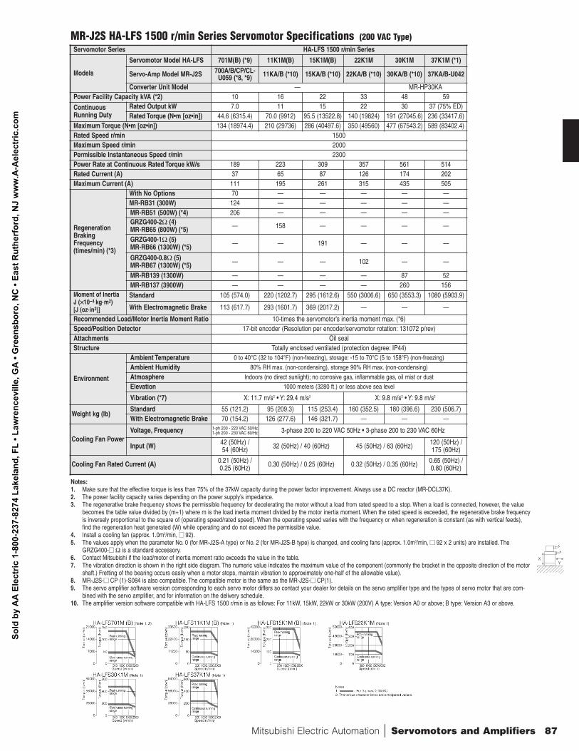
Servomotor Series HA-LFS 1500 r/min Series
Models
Servomotor Model HA-LFS 701M(B) (*9) 11K1M(B) 15K1M(B) 22K1M 30K1M 37K1M (*1)
Servo-Amp Model MR-J2S 700A/B/CP/CL-U059 (*8, *9) 11KA/B (*10) 15KA/B (*10) 22KA/B (*10) 30KA/B (*10) 37KA/B-U042
Converter Unit Model — MR-HP30KAPower Facility Capacity kVA (*2) 10 16 22 33 48 59
ContinuousRunning Duty
Rated Output kW 7.0 11 15 22 30 37 (75% ED)Rated Torque (N•m [oz•in]) 44.6 (6315.4) 70.0 (9912) 95.5 (13522.8) 140 (19824) 191 (27045.6) 236 (33417.6)
Maximum Torque (N•m [oz•in]) 134 (18974.4) 210 (29736) 286 (40497.6) 350 (49560) 477 (67543.2) 589 (83402.4)Rated Speed r/min 1500Maximum Speed r/min 2000Permissible Instantaneous Speed r/min 2300Power Rate at Continuous Rated Torque kW/s 189 223 309 357 561 514Rated Current (A) 37 65 87 126 174 202Maximum Current (A) 111 195 261 315 435 505
RegenerationBrakingFrequency(times/min) (*3)
With No Options 70 — — — — —MR-RB31 (300W) 124 — — — — —MR-RB51 (500W) (*4) 206 — — — — —GRZG400-2Ω (4)MR-RB65 (800W) (*5) — 158 — — — —
GRZG400-1Ω (5)MR-RB66 (1300W) (*5) — — 191 — — —
GRZG400-0.8Ω (5)MR-RB67 (1300W) (*5) — — — 102 — —
MR-RB139 (1300W) — — — — 87 52MR-RB137 (3900W) — — — — 260 156
Moment of InertiaJ (××10-4 kg.m2) [J (oz.in2)]
Standard 105 (574.0) 220 (1202.7) 295 (1612.6) 550 (3006.6) 650 (3553.3) 1080 (5903.9)
With Electromagnetic Brake 113 (617.7) 293 (1601.7) 369 (2017.2) — — —
Recommended Load/Motor Inertia Moment Ratio 10-times the servomotor’s inertia moment max. (*6)Speed/Position Detector 17-bit encoder (Resolution per encoder/servomotor rotation: 131072 p/rev)Attachments Oil sealStructure Totally enclosed ventilated (protection degree: IP44)
Environment
Ambient Temperature 0 to 40°C (32 to 104°F) (non-freezing), storage: -15 to 70°C (5 to 158°F) (non-freezing)
Ambient Humidity 80% RH max. (non-condensing), storage 90% RH max. (non-condensing)
Atmosphere Indoors (no direct sunlight); no corrosive gas, inflammable gas, oil mist or dust
Elevation 1000 meters (3280 ft.) or less above sea level
Vibration (*7) X: 11.7 m/s2 • Y: 29.4 m/s2 X: 9.8 m/s2 • Y: 9.8 m/s2
Weight kg (lb)Standard 55 (121.2) 95 (209.3) 115 (253.4) 160 (352.5) 180 (396.6) 230 (506.7)With Electromagnetic Brake 70 (154.2) 126 (277.6) 146 (321.7) — — —
Cooling Fan PowerVoltage, Frequency 1-ph 200 - 220 VAC 50/Hz
1-ph 200 - 230 VAC 60/Hz 3-phase 200 to 220 VAC 50Hz • 3-phase 200 to 230 VAC 60Hz
Input (W) 42 (50Hz) / 54 (60Hz) 32 (50Hz) / 40 (60Hz) 45 (50Hz) / 63 (60Hz) 120 (50Hz) /
175 (60Hz)
Cooling Fan Rated Current (A) 0.21 (50Hz) /0.25 (60Hz) 0.30 (50Hz) / 0.25 (60Hz) 0.32 (50Hz) / 0.35 (60Hz) 0.65 (50Hz) /
0.80 (60Hz)
MR-J2S HA-LFS 1500 r/min Series Servomotor Specifications (200 VAC Type)
Notes:1. Make sure that the effective torque is less than 75% of the 37kW capacity during the power factor improvement. Always use a DC reactor (MR-DCL37K).2. The power facility capacity varies depending on the power supply’s impedance.3. The regenerative brake frequency shows the permissible frequency for decelerating the motor without a load from rated speed to a stop. When a load is connected, however, the value
becomes the table value divided by (m+1) where m is the load inertia moment divided by the motor inertia moment. When the rated speed is exceeded, the regenerative brake frequencyis inversely proportional to the square of (operating speed/rated speed). When the operating speed varies with the frequency or when regeneration is constant (as with vertical feeds),find the regeneration heat generated (W) while operating and do not exceed the permissible value.
4. Install a cooling fan (approx. 1.0m3/min, nn 92).5. The values apply when the parameter No. 0 (for MR-J2S-A type) or No. 2 (for MR-J2S-B type) is changed, and cooling fans (approx. 1.0m3/min, nn 92 x 2 units) are installed. The
GRZG400-nn Ω is a standard accessory.6. Contact Mitsubishi if the load/motor of inertia moment ratio exceeds the value in the table.7. The vibration direction is shown in the right side diagram. The numeric value indicates the maximum value of the component (commonly the bracket in the opposite direction of the motor
shaft.) Fretting of the bearing occurs easily when a motor stops, maintain vibration to approximately one-half of the allowable value).8. MR-J2S-nn CP (1)-S084 is also compatible. The compatible motor is the same as the MR-J2S-nn CP(1).9. The servo amplifier software version corresponding to each servo motor differs so contact your dealer for details on the servo amplifier type and the types of servo motor that are com-
bined with the servo amplifier, and for information on the delivery schedule.10. The amplifier version software compatible with HA-LFS 1500 r/min is as follows: For 11kW, 15kW, 22kW or 30kW (200V) A type: Version A0 or above; B type: Version A3 or above.
XY
Mitsubishi Electric Automation | Servomotors and Amplifiers 87
Sold
by
AA
Ele
ctric
1-8
00-2
37-8
274
Lake
land
, FL
• Law
renc
evill
e, G
A •
Gre
ensb
oro,
NC
• Ea
st R
uthe
rfor
d, N
J w
ww
.A-A
elec
tric
.com
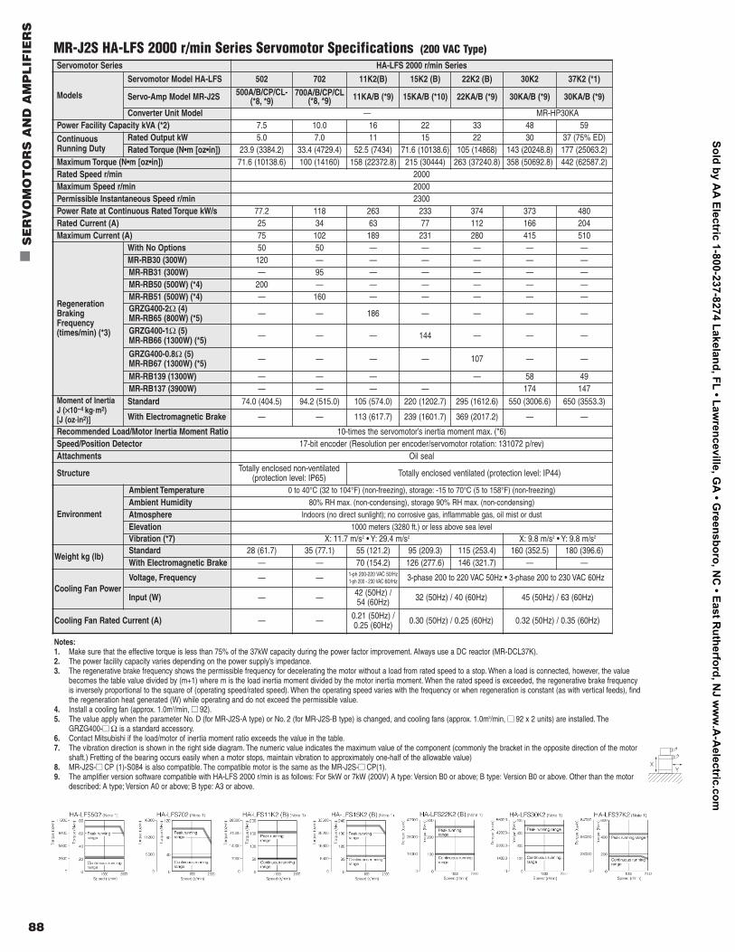
88
n
SE
RV
OM
OT
OR
S A
ND
AM
PL
IFIE
RS
Servomotor Series HA-LFS 2000 r/min Series
Models
Servomotor Model HA-LFS 502 702 11K2(B) 15K2 (B) 22K2 (B) 30K2 37K2 (*1)
Servo-Amp Model MR-J2S 500A/B/CP/CL-(*8, *9)
700A/B/CP/CL(*8, *9) 11KA/B (*9) 15KA/B (*10) 22KA/B (*9) 30KA/B (*9) 30KA/B (*9)
Converter Unit Model — MR-HP30KAPower Facility Capacity kVA (*2) 7.5 10.0 16 22 33 48 59
ContinuousRunning Duty
Rated Output kW 5.0 7.0 11 15 22 30 37 (75% ED)Rated Torque (N•m [oz•in]) 23.9 (3384.2) 33.4 (4729.4) 52.5 (7434) 71.6 (10138.6) 105 (14868) 143 (20248.8) 177 (25063.2)
Maximum Torque (N•m [oz•in]) 71.6 (10138.6) 100 (14160) 158 (22372.8) 215 (30444) 263 (37240.8) 358 (50692.8) 442 (62587.2)Rated Speed r/min 2000Maximum Speed r/min 2000Permissible Instantaneous Speed r/min 2300Power Rate at Continuous Rated Torque kW/s 77.2 118 263 233 374 373 480Rated Current (A) 25 34 63 77 112 166 204Maximum Current (A) 75 102 189 231 280 415 510
RegenerationBrakingFrequency(times/min) (*3)
With No Options 50 50 — — — — —MR-RB30 (300W) 120 — — — — — —MR-RB31 (300W) — 95 — — — — —MR-RB50 (500W) (*4) 200 — — — — — — MR-RB51 (500W) (*4) — 160 — — — — — GRZG400-2Ω (4)MR-RB65 (800W) (*5) — — 186 — — — —
GRZG400-1Ω (5)MR-RB66 (1300W) (*5) — — — 144 — — —
GRZG400-0.8Ω (5)MR-RB67 (1300W) (*5) — — — — 107 — —
MR-RB139 (1300W) — — — — 58 49MR-RB137 (3900W) — — — — 174 147
Moment of InertiaJ (××10-4 kg.m2) [J (oz.in2)]
Standard 74.0 (404.5) 94.2 (515.0) 105 (574.0) 220 (1202.7) 295 (1612.6) 550 (3006.6) 650 (3553.3)
With Electromagnetic Brake — — 113 (617.7) 239 (1601.7) 369 (2017.2) — —
Recommended Load/Motor Inertia Moment Ratio 10-times the servomotor’s inertia moment max. (*6)Speed/Position Detector 17-bit encoder (Resolution per encoder/servomotor rotation: 131072 p/rev)Attachments Oil seal
Structure Totally enclosed non-ventilated (protection level: IP65) Totally enclosed ventilated (protection level: IP44)
Environment
Ambient Temperature 0 to 40°C (32 to 104°F) (non-freezing), storage: -15 to 70°C (5 to 158°F) (non-freezing)
Ambient Humidity 80% RH max. (non-condensing), storage 90% RH max. (non-condensing)
Atmosphere Indoors (no direct sunlight); no corrosive gas, inflammable gas, oil mist or dust
Elevation 1000 meters (3280 ft.) or less above sea levelVibration (*7) X: 11.7 m/s2 • Y: 29.4 m/s2 X: 9.8 m/s2 • Y: 9.8 m/s2
Weight kg (lb)Standard 28 (61.7) 35 (77.1) 55 (121.2) 95 (209.3) 115 (253.4) 160 (352.5) 180 (396.6)With Electromagnetic Brake — — 70 (154.2) 126 (277.6) 146 (321.7) — —
Cooling Fan PowerVoltage, Frequency — — 1-ph 200-220 VAC 50/Hz
1-ph 200 - 230 VAC 60/Hz 3-phase 200 to 220 VAC 50Hz • 3-phase 200 to 230 VAC 60Hz
Input (W) — — 42 (50Hz) / 54 (60Hz) 32 (50Hz) / 40 (60Hz) 45 (50Hz) / 63 (60Hz)
Cooling Fan Rated Current (A) — — 0.21 (50Hz) /0.25 (60Hz) 0.30 (50Hz) / 0.25 (60Hz) 0.32 (50Hz) / 0.35 (60Hz)
MR-J2S HA-LFS 2000 r/min Series Servomotor Specifications (200 VAC Type)
Notes:1. Make sure that the effective torque is less than 75% of the 37kW capacity during the power factor improvement. Always use a DC reactor (MR-DCL37K).2. The power facility capacity varies depending on the power supply’s impedance.3. The regenerative brake frequency shows the permissible frequency for decelerating the motor without a load from rated speed to a stop. When a load is connected, however, the value
becomes the table value divided by (m+1) where m is the load inertia moment divided by the motor inertia moment. When the rated speed is exceeded, the regenerative brake frequencyis inversely proportional to the square of (operating speed/rated speed). When the operating speed varies with the frequency or when regeneration is constant (as with vertical feeds), findthe regeneration heat generated (W) while operating and do not exceed the permissible value.
4. Install a cooling fan (approx. 1.0m3/min, nn 92).5. The value apply when the parameter No. D (for MR-J2S-A type) or No. 2 (for MR-J2S-B type) is changed, and cooling fans (approx. 1.0m3/min, nn 92 x 2 units) are installed. The
GRZG400-nn Ω is a standard accessory.6. Contact Mitsubishi if the load/motor of inertia moment ratio exceeds the value in the table.7. The vibration direction is shown in the right side diagram. The numeric value indicates the maximum value of the component (commonly the bracket in the opposite direction of the motor
shaft.) Fretting of the bearing occurs easily when a motor stops, maintain vibration to approximately one-half of the allowable value)8. MR-J2S-nn CP (1)-S084 is also compatible. The compatible motor is the same as the MR-J2S-nn CP(1).9. The amplifier version software compatible with HA-LFS 2000 r/min is as follows: For 5kW or 7kW (200V) A type: Version B0 or above; B type: Version B0 or above. Other than the motor
described: A type; Version A0 or above; B type: A3 or above.
XY
Sold by AA
Electric 1-800-237-8274 Lakeland, FL • Lawrenceville, G
A • G
reensboro, NC
• East Rutherford, N
J ww
w.A
-Aelectric.com
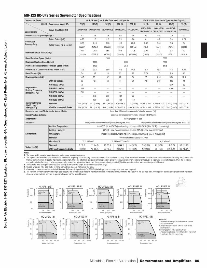
Mitsubishi Electric Automation | Servomotors and Amplifiers 89
MR-J2S HC-UFS Series Servomotor SpecificationsServomotor Series HC-UFS 2000 (Low Profile Type, Medium Capacity) HC-UFS 3000 (Low Profile Type, Medium Capacity)
Servomotor Model HC- 72 (B) 152 (B) 202 (B) 352 (B) 502 (B) 13 (B) 23 (B) 43 (B) 73 (B)
Servo-Amp Model MR- 70A/B/CP/CL 200A/B/CP/CL 350A/B/CP/CL 500A/B/CP/CL 500A/B/CP/CL10A/A1/B/B1 20A/A1/B/B1 40A/A1/B/B1
70A/B/CP/CLCP/CP1/CL/CL1 CP/CP1/CL/CL1 CP/CP1/CL/CL1
Power Facility Capacity (kVA) (*1) 1.3 2.5 3.5 5.5 7.5 0.3 0.5 0.9 1.3
Rated Output (kW) 0.75 1.5 2.0 3.5 5.0 0.1 0.2 0.4 0.75
Rated Torque (N.m [oz.in])3.58 7.16 9.55 16.7 23.9 0.32 0.64 1.3 2.4
(506.9) (1013.8) (1352.3) (2364.9) (3384.5) (45.3) (90.6) (184.1) (339.8)
Maximum Torque (N.m [oz.in])10.7 21.6 28.5 50.1 71.6 0.95 1.9 3.8 7.2
(1515.1) (3058.5) (4035.5) (7094.8) (10139.4) (134.5) (269.0) (538.1) (1019.5)
Rated Rotation Speed (r/min) 2000 3000
Maximum Rotation Speed (r/min) 3000 2500 4500
Permissible Instantaneous Rotation Speed (r/min) 3450 2875 5175
Power Rate at Continuous Rated Torque (kW/s) 12.3 23.2 23.9 36.5 49.6 15.5 19.2 47.7 9.66
Rated Current (A) 5.4 9.7 14 23 28 0.76 1.5 2.8 4.3
Maximum Current (A) 16.2 29.1 42 68 84 2.5 4.95 9.24 12.9
With No Options 53 124 68 44 31 (*3) (*3) 410 41
MR-RB032 (30W) 79 — — — — — — 1230 62
MR-RB12 (100W) 264 — — — — — — 4100 206
MR-RB32 (300W) 791 — — — — — — — —
MR-RB30 (300W) — 372 203 102 72 — — — —
MR-RB50 (500W) — 620 338 169 119 — — — —
Standard 10.4 (56.9) 22.1 (120.8) 38.2 (208.9) 76.5 (418.3) 115 (628.8) 0.066 (0.361) 0.241 (1.315) 0.365 (1.994) 5.90 (32.2)
With Electromagnetic Brake 12.4 (67.8) 24.1 (131.8) 46.8 (255.9) 85.1 (465.3) 123.6 (675.8) 0.074 (0.404) 0.323 (1.762) 0.447 (2.445) 6.10 (33.3)
Recommended Load/Motor Inertia Moment Ratio Less than 15-times the servomotor's inertia moment (*4)
Speed/Position Detector Resolution per encoder/servomotor rotation: 131072 p/rev
Attachments 17 bit encoder, oil seal
Structure Totally enclosed non-ventilated (protection degree: IP65) Totally enclosed non-ventilated (protection degree: IP65) (*5)
Ambient Temperature 0 to 40°C (32 to 104°F) (non-freezing), storage: −15 to 70°C (5 to 158°F) (non-freezing)
Ambient Humidity 80% RH max. (non-condensing), storage: 90% RH max. (non-condensing)
Atmosphere Indoors (no direct sunlight); no corrosive gas, inflammable gas, oil mist, or dust
Elevation 1000 meters or less above sea level
Vibration (*6) X, Y: 24.5m/s2 X: 24.5m/s2; Y: 49m/s2 X, Y: 49m/s2
Weight kg (lb)Standard 8 (17.6) 11 (24.3) 16 (35.3) 20 (44.1) 24 (52.9) 0.8 (1.76) 1.5 (3.31) 1.7 (3.75) 5.0 (11.02)
With Electromagnetic Brake 10 (22.0) 13 (28.7) 22 (48.5) 26 (57.3) 30 (66.1) 1.2 (2.65) 2.2 (4.85) 2.4 (5.29) 6.2 (13.67)
Regeneration Braking Frequency(times/min) (*2)
Moment of Inertia J (××10-4 kg.m2) [WK2 (oz.in
2)]
Continuous Running Duty
Specifications
Models
Environment
Notes:1. The power facility capacity varies depending on the power supply's impedance.2. The regenerative brake frequency shown is the permissible frequency for decelerating a stand-alone motor from rated rpm to a stop. When under load, however, the value becomes the table value divided by (m+1) where m is
the load inertia moment divided by the motor inertia moment. When the rated rpm is exceeded, the regenerative brake frequency is inversely proportional to the square of (operating speed/rated speed). When the operatingrpm varies with the frequency or when regeneration is constant (as with vertical feeds), find the regeneration heat generated (W) while operating and do not exceed the permissible value.
3. There are no limits on regeneration frequency as long as the effective torque is within the rated torque range.4. Contact Mitsubishi if the load/ motor of inertia moment ratio exceeds the figure in the table.5. Connector for cable terminal are excluded. However, IP65-compliant products (HC-UFSM-S1) including connector components have been prepared.6. The vibration direction is shown in the right-side diagram. The numeric value indicates the maximum value of the component (commonly the bracket on the anti-load side). Fretting of the bearing occurs easily when the motor
stops, so please maintain vibration to approximately one-half the allowable value.
XY
1000 2000 3000
30
20
10
0
4200
2800
1400
0
Rotation speed (r/min)
Torq
ue (o
z•in
)
Torq
ue (N
• m)
HC-UFS202 (B)
1000 2000 3000 4000 4500
1.0
0.75
0.5
0.25
0
140
105
70
35
0
Rotation speed (r/min)
Torq
ue (o
z•in
)
Torq
ue (N
• m)
HC-UFS13 (B)
1000 2000 3000 4000 4500
2.0
1.5
1.0
0.5
0
280
210
140
70
0
Rotation speed (r/min)
Torq
ue (o
z•in
)
Torq
ue (N
• m)
HC-UFS23 (B)
1000 2000 3000 4000 4500
4.0
3.0
2.0
1.0
0
560
420
280
140
0
Rotation speed (r/min)
Torq
ue (o
z•in
)
Torq
ue (N
• m)
HC-UFS43 (B)
1000 2000 3000 4000 4500
8.0
6.0
4.0
2.0
0
1120
840
560
280
0
Rotation speed (r/min)
Torq
ue (o
z•in
)
Torq
ue (N
• m)
HC-UFS73 (B)
1000 2000 3000
12
8
4
0
1680
1120
560
0
Rotation speed (r/min)
Torq
ue (o
z•in
)
Torq
ue (N
• m)
HC-UFS72 (B)
1000 2000 3000
24
16
8
0
3360
2240
1120
0
Rotation speed (r/min)
Torq
ue (o
z•in
)
Torq
ue (N
• m)
HC-UFS152 (B)
1000 2000 2500
60
40
20
0
8400
5600
2800
0
Rotation speed (r/min)
Torq
ue (o
z•in
)
Torq
ue (N
• m)
HC-UFS352 (B)
Continuous running range
Peak running range
1000 2000 2500
80
60
40
20
0
11200
8400
5600
2800
0
Rotation speed (r/min)
Torq
ue (o
z•in
)
Torq
ue (N
• m)
HC-UFS502 (B)
Continuous running range
Peak running range
Continuous running range
Peak running range
Continuous running range
Peak running range
Peak running range
Continuous running range
Peak running range
Continuous running range
Continuous running range
Peak running range
Peak running range
Continuous running range
Peak running range
Continuous running range
Remarks: 1. Solid lines show torque characteristics for 3-phase
200-230V operation. 2. Torque characteristics are same for single-phase
230V operation. 3. For single-phase 100V operation, torque
characteristics that are different from above-mentioned 1 and 2, are shown in broken lines.
Sold
by
AA
Ele
ctric
1-8
00-2
37-8
274
Lake
land
, FL
• Law
renc
evill
e, G
A •
Gre
ensb
oro,
NC
• Ea
st R
uthe
rfor
d, N
J w
ww
.A-A
elec
tric
.com
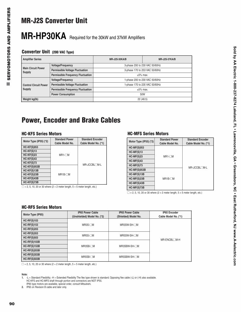
90
n
SE
RV
OM
OT
OR
S A
ND
AM
PL
IFIE
RS
Converter Unit (200 VAC Type)
Conforms to following standards: EN, UL, cUL
131072 pulse p/revencoder for use in absolute andincremental systems (serial encoder)
8192 pulse p/revencoder for use in absolute andincremental systems (serial encoder)
HC- FSServomotor Selection:
Symbol
05
1 to 8
10 to 70
Rated OutputCapacity (kW)*
0.05
0.1 to 0.85
1.0 to 7.0
Symbol
1
2
3
Rated Speed (r/min)
1000
2000
3000
Symbol
M
K
S
R
U
Motor Series
Ultra-low inertia, small capacity
Low inertia, small capacity
Medium inertia, medium capacity
Low inertia, medium capacity
Low profile type, small-medium capacity
Symbol
None
B
ElectromagneticBrake
—
Installed
Symbol
None
K
D
Shaft
Special Order
Keyway (*1) (Standard)
D-cut (* 2) (Special Order)
Notes:1. Key not available for HC-KFS, HC-MFS and HC-UFS (3000 r/min) models under 200W.2. The D-cut is available only for the HC-KFS, HC-MFS and HC-UFS models of 100W or less.
MR-J2S-Servo Amplifier Selection:
MELSERVO-J2-Super Series
Conforms to following standards: EN, UL, cUL
Compatible motor model
Symbol
None
1
Power Supply
3-phase 200V AC orsingle-phase 230V AC *
Single-phase AC 100V **
Symbol
10
20
40
60
70
100
200
350
500
700
11K
15K
22K
30K
37K
HC-MFS
053, 13
23
43
—
73
—
—
—
—
—
—
—
—
—
—
HC-SFS
—
—
—
52, 53
—
81, 102, 103
121, 201, 152, 202, 153, 203
301, 352, 353
502
702
—
—
—
—
—
HC-RFS
—
—
—
—
—
—
103, 153
203
353, 503
—
—
—
—
—
—
HC-UFS
13
23
43
—
72, 73
—
152
202
352, 502
—
—
—
—
—
—
HA-LFS
—
—
—
—
—
—
—
—
502
601, 701, 702
801, 12K1, 11K1M, 1 1K2
15K1, 15K1M, 15K2
20K1, 25K1, 22K1M, 22K2
30K2
37K2
HC-KFS
053, 13
23
43
—
73
—
—
—
—
—
—
—
—
—
—
* Only servo-amplifier for MR-J2S-70 or less.** Only servo-amplifier for MR-J2S-40 or less.
Note: CP & CL available up to M R-J2S-700
Symbol
None
-S084
-Sxxx
Description
Standard specification
CC-Lin k for CP Type only*
Special specifications
Rated speed3000 [r/min]
Input power supply form
HA-FFServomotor Selection:
Symbol
05
1
2
3
4
6
Rated OutputCapacity (W)
50
100
200
300
400
600
3 C
Symbol
C
EN-UL/c-UL StandardComplient Model
Cannon connector
Symbol
None
B
—
Installed
-UE
* Check specifications for allavailable motor size capabilities.
* Must use CC-Lin k Interface Module MR-J2S-T01 for CC-Lin k communication
Symbol
A
B
CP
CL
Description
General purpose interface (analog speed, analog torque,
pulse train)
SSCNET
Motion point t able
Motion program
ElectromagneticBrake
Conforms to following standards: EN, UL, cUL
131072 pulse p/revencoder for use in absolute andincremental systems (serial encoder)
HA-LFSServomotor Selection:
Symbol
50 to 80
11k to 37k
Rated OutputCapacity (kW)*
5 to 8
11 to 37
Symbol
1
1M
2
Rated Speed (r/min)
1000
1500
2000
Symbol
None
B
ElectromagneticBrake
—
Installed
Symbol
None
K
Shaft
Straight
Keyway (Standard)
* The HA-LFS 1000 r/min 8.0 to 25 kW capacities are special-order products
MR-HP30KA Required for the 30kW and 37kW Amplifiers
Converter Selection:
Amplifier Series MR-J2S-30KA/B MR-J2S-37KA/B
Main Circuit PowerSupply
Voltage/Frequency 3-phase 200 to 230 VAC 50/60Hz
Permissible Voltage Fluctuation 3-phase 170 to 253 VAC 50/60Hz
Permissible Frequency Fluctuation ±5% max.
Control Circuit PowerSupply
Voltage/Frequency 1-phase 200 to 230 VAC 50/60Hz
Permissible Voltage Fluctuation 1-phase 170 to 235 VAC 50/60Hz
Permissible Frequency Fluctuation ±5% max.
Power Consumption 50W
Weight kg(lb) 22 (48.5)
Power, Encoder and Brake Cables
HC-MFS Series Motors
nn = 2, 5, 10, 20 or 30 where (2 = 2 meter length, 5 = 5 meter length, etc.)
Motor Type (IP55) (*2)Standard Power Cable Model No.
Standard Encoder Cable Model No. (*1)
HC-MF(S)053
MR1-nnM
MR-JCCBLnnM-L
HC-MF(S)13
HC-MF(S)23
HC-MF(S)43
HC-MF(S)73
HC-MF(S)053B
MR1B-nnM
HC-MF(S)13B
HC-MF(S)23B
HC-MF(S)43B
HC-MF(S)73B
HC-KFS Series MotorsMotor Type (IP55) (*2)
Standard Power Cable Model No.
Standard Encoder Cable Model No. (*1)
HC-KF(S)053
MR1-nnM
MR-JCCBLnnM-L
HC-KF(S)13HC-KF(S)23HC-KF(S)43HC-KF(S)73HC-KF(S)053B
MR1B-nnMHC-KF(S)13BHC-KF(S)23BHC-KF(S)43BHC-KF(S)73B
nn = 2, 5, 10, 20 or 30 where (2 = 2 meter length, 5 = 5 meter length, etc.)
HC-RFS Series MotorsMotor Type (IP65)
IP65 Power Cable (Unshielded) Model No. (*2)
IP65 Power Cable (Shielded) Model No.
IP65 Encoder Cable Model No. (*1)
HC-RF(S)103MR3S-nnM MR3SW-SH-nnM
MR-ENCBLnnM-H
HC-RF(S)153HC-RF(S)203HC-RF(S)353
MR5S-nnM MR5SW-SH-nnMHC-RF(S)503HC-RF(S)103B
MR3SB-nnM MR3SBW-SH-nnMHC-RF(S)153BHC-RF(S)203BHC-RF(S)353B
MR5SB-nnM MR5SBW-SH-nnMHC-RF(S)503B
nn = 2, 5, 10, 20 or 30 where (2 = 2 meter length, 5 = 5 meter length, etc.)
Note:1. -L = Standard Flexibility; -H = Extended Flexibility The flex type shown is standard. Opposing flex cable (-L) or (-H) also available.
HC-KFS and HC-MFS shaft through portion and connectors are NOT IP55.IP65 type motors are available, special order, consult Mitsubishi.
2. IP65 on Revision B cable and later only.
MR-J2S Converter Unit
Sold by AA
Electric 1-800-237-8274 Lakeland, FL • Lawrenceville, G
A • G
reensboro, NC
• East Rutherford, N
J ww
w.A
-Aelectric.com
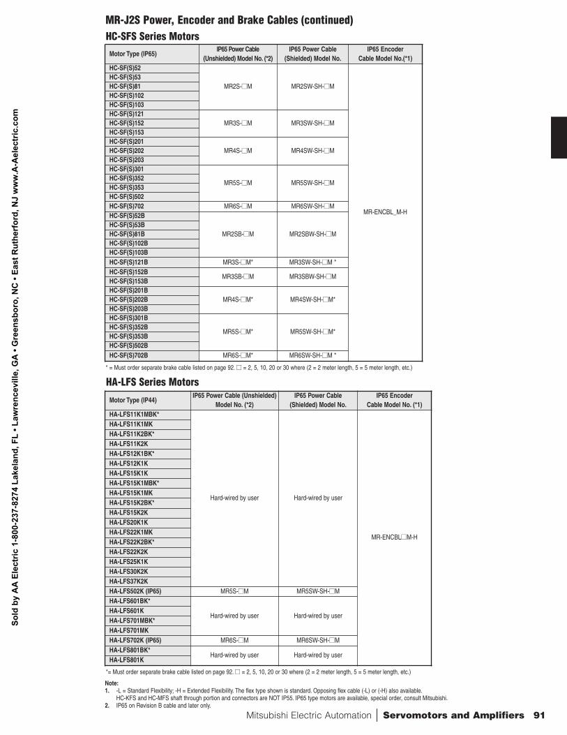
Mitsubishi Electric Automation | Servomotors and Amplifiers 91
HA-LFS Series Motors
Motor Type (IP44)IP65 Power Cable (Unshielded)
Model No. (*2)IP65 Power Cable
(Shielded) Model No.IP65 Encoder
Cable Model No. (*1)HA-LFS11K1MBK*
Hard-wired by user Hard-wired by user
MR-ENCBLnnM-H
HA-LFS11K1MKHA-LFS11K2BK*HA-LFS11K2KHA-LFS12K1BK*HA-LFS12K1KHA-LFS15K1KHA-LFS15K1MBK*HA-LFS15K1MKHA-LFS15K2BK*HA-LFS15K2KHA-LFS20K1KHA-LFS22K1MKHA-LFS22K2BK*HA-LFS22K2KHA-LFS25K1KHA-LFS30K2KHA-LFS37K2KHA-LFS502K (IP65) MR5S-nnM MR5SW-SH-nnM HA-LFS601BK*
Hard-wired by user Hard-wired by userHA-LFS601KHA-LFS701MBK*HA-LFS701MKHA-LFS702K (IP65) MR6S-nnM MR6SW-SH-nnM HA-LFS801BK*
Hard-wired by user Hard-wired by userHA-LFS801K
*= Must order separate brake cable listed on page 92. nn = 2, 5, 10, 20 or 30 where (2 = 2 meter length, 5 = 5 meter length, etc.)
HC-SFS Series Motors
* = Must order separate brake cable listed on page 92. nn = 2, 5, 10, 20 or 30 where (2 = 2 meter length, 5 = 5 meter length, etc.)
Motor Type (IP65)IP65 Power Cable
(Unshielded) Model No. (*2)IP65 Power Cable
(Shielded) Model No.IP65 Encoder
Cable Model No.(*1)HC-SF(S)52
MR2S-nnM MR2SW-SH-nnM
MR-ENCBL_M-H
HC-SF(S)53HC-SF(S)81HC-SF(S)102HC-SF(S)103HC-SF(S)121
MR3S-nnM MR3SW-SH-nnMHC-SF(S)152HC-SF(S)153HC-SF(S)201
MR4S-nnM MR4SW-SH-nnM HC-SF(S)202HC-SF(S)203HC-SF(S)301
MR5S-nnM MR5SW-SH-nnM HC-SF(S)352HC-SF(S)353HC-SF(S)502HC-SF(S)702 MR6S-nnM MR6SW-SH-nnM HC-SF(S)52B
MR2SB-nnM MR2SBW-SH-nnM HC-SF(S)53BHC-SF(S)81BHC-SF(S)102BHC-SF(S)103BHC-SF(S)121B MR3S-nnM* MR3SW-SH-nnM *HC-SF(S)152B
MR3SB-nnM MR3SBW-SH-nnMHC-SF(S)153BHC-SF(S)201B
MR4S-nnM* MR4SW-SH-nnM*HC-SF(S)202BHC-SF(S)203BHC-SF(S)301B
MR5S-nnM* MR5SW-SH-nnM*HC-SF(S)352BHC-SF(S)353BHC-SF(S)502BHC-SF(S)702B MR6S-nnM* MR6SW-SH-nnM *
Note:1. -L = Standard Flexibility; -H = Extended Flexibility. The flex type shown is standard. Opposing flex cable (-L) or (-H) also available.
HC-KFS and HC-MFS shaft through portion and connectors are NOT IP55. IP65 type motors are available, special order, consult Mitsubishi.2. IP65 on Revision B cable and later only.
MR-J2S Power, Encoder and Brake Cables (continued)
Sold
by
AA
Ele
ctric
1-8
00-2
37-8
274
Lake
land
, FL
• Law
renc
evill
e, G
A •
Gre
ensb
oro,
NC
• Ea
st R
uthe
rfor
d, N
J w
ww
.A-A
elec
tric
.com
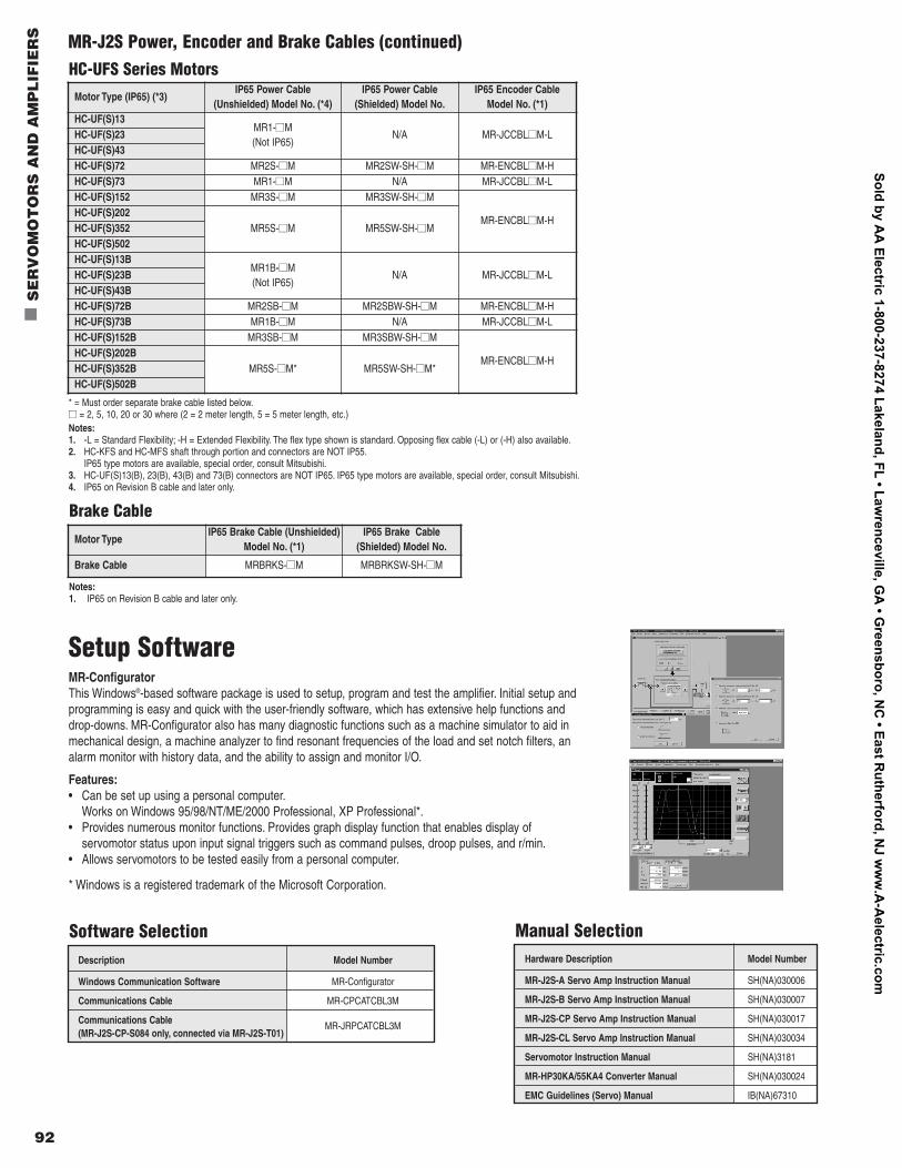
92
n
SE
RV
OM
OT
OR
S A
ND
AM
PL
IFIE
RS
HC-UFS Series MotorsMotor Type (IP65) (*3)
IP65 Power Cable(Unshielded) Model No. (*4)
IP65 Power Cable(Shielded) Model No.
IP65 Encoder Cable Model No. (*1)
HC-UF(S)13MR1-nnM(Not IP65)
N/A MR-JCCBLnnM-LHC-UF(S)23HC-UF(S)43HC-UF(S)72 MR2S-nnM MR2SW-SH-nnM MR-ENCBLnnM-HHC-UF(S)73 MR1-nnM N/A MR-JCCBLnnM-LHC-UF(S)152 MR3S-nnM MR3SW-SH-nnM
MR-ENCBLnnM-HHC-UF(S)202
MR5S-nnM MR5SW-SH-nnMHC-UF(S)352HC-UF(S)502HC-UF(S)13B
MR1B-nnM(Not IP65)
N/A MR-JCCBLnnM-LHC-UF(S)23BHC-UF(S)43BHC-UF(S)72B MR2SB-nnM MR2SBW-SH-nnM MR-ENCBLnnM-HHC-UF(S)73B MR1B-nnM N/A MR-JCCBLnnM-LHC-UF(S)152B MR3SB-nnM MR3SBW-SH-nnM
MR-ENCBLnnM-HHC-UF(S)202B
MR5S-nnM* MR5SW-SH-nnM*HC-UF(S)352BHC-UF(S)502B
Brake Cable
Motor TypeIP65 Brake Cable (Unshielded)
Model No. (*1)IP65 Brake Cable
(Shielded) Model No.
Brake Cable MRBRKS-nnM MRBRKSW-SH-nnM
Notes:1. -L = Standard Flexibility; -H = Extended Flexibility. The flex type shown is standard. Opposing flex cable (-L) or (-H) also available.2. HC-KFS and HC-MFS shaft through portion and connectors are NOT IP55.
IP65 type motors are available, special order, consult Mitsubishi.3. HC-UF(S)13(B), 23(B), 43(B) and 73(B) connectors are NOT IP65. IP65 type motors are available, special order, consult Mitsubishi.4. IP65 on Revision B cable and later only.
* = Must order separate brake cable listed below.nn = 2, 5, 10, 20 or 30 where (2 = 2 meter length, 5 = 5 meter length, etc.)
Setup SoftwareMR-ConfiguratorThis Windows®-based software package is used to setup, program and test the amplifier. Initial setup andprogramming is easy and quick with the user-friendly software, which has extensive help functions anddrop-downs. MR-Configurator also has many diagnostic functions such as a machine simulator to aid inmechanical design, a machine analyzer to find resonant frequencies of the load and set notch filters, analarm monitor with history data, and the ability to assign and monitor I/O.
Features:• Can be set up using a personal computer.
Works on Windows 95/98/NT/ME/2000 Professional, XP Professional*.• Provides numerous monitor functions. Provides graph display function that enables display of
servomotor status upon input signal triggers such as command pulses, droop pulses, and r/min.• Allows servomotors to be tested easily from a personal computer.
* Windows is a registered trademark of the Microsoft Corporation.
Description Model Number
Windows Communication Software MR-Configurator
Communications Cable MR-CPCATCBL3M
Communications Cable (MR-J2S-CP-S084 only, connected via MR-J2S-T01)
MR-JRPCATCBL3M
Software SelectionHardware Description Model Number
MR-J2S-A Servo Amp Instruction Manual SH(NA)030006
MR-J2S-B Servo Amp Instruction Manual SH(NA)030007
MR-J2S-CP Servo Amp Instruction Manual SH(NA)030017
MR-J2S-CL Servo Amp Instruction Manual SH(NA)030034
Servomotor Instruction Manual SH(NA)3181
MR-HP30KA/55KA4 Converter Manual SH(NA)030024
EMC Guidelines (Servo) Manual IB(NA)67310
Manual Selection
Notes:1. IP65 on Revision B cable and later only.
MR-J2S Power, Encoder and Brake Cables (continued)
Sold by AA
Electric 1-800-237-8274 Lakeland, FL • Lawrenceville, G
A • G
reensboro, NC
• East Rutherford, N
J ww
w.A
-Aelectric.com
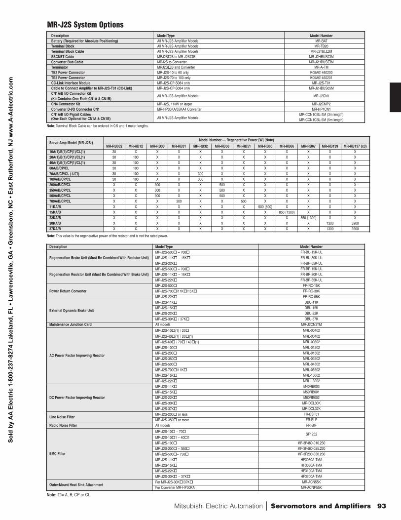
Mitsubishi Electric Automation | Servomotors and Amplifiers 93
Note: Terminal Block Cable can be ordered in 0.5 and 1 meter lengths.
Note: This value is the regenerative power of the resistor and is not the rated power.
Description Model Type Model NumberBattery (Required for Absolute Positioning) All MR-J2S Amplifier Models MR-BATTerminal Block All MR-J2S Amplifier Models MR-TB20Terminal Block Cable All MR-J2S Amplifier Models MR-J2TBLo
MSSCNET Cable MRJ2So
B to MR-J2So
B MR-J2HBUSo
MConverter Bus Cable MRJ2S to Converter MR-J2HBUSo
MTerminator MRJ2So
B and Converter MR-A-TMTE2 Power Connector MR-J2S-10 to 60 only K05A01460200TE2 Power Connector MR-J2S-70 to 100 only K05A01460201CC-Link Interface Module MR-J2S-CP-S084 only MR-J2S-T01Cable to Connect Amplifier to MR-J2S-T01 (CC-Link) MR-J2S-CP-S084 only MR-J2HBUS05MCN1A/B I/O Connector Kit (Kit Contains One Each CN1A & CN1B)
All MR-J2S Amplifier Models MR-J2CN1
CN4 Connector Kit MR-J2S, 11kW or larger MR-J2CMP2Converter D-I/O Connector CN1 MR-HP30KA/55KA4 Converter MR-HP4CN1CN1A/B I/O Pigtail Cables MR-CCN1CBL-3M (3m length)(One Each Optional for CN1A & CN1B) All MR-J2S Amplifier Models MR-CCN1CBL-5M (5m length)
MR-J2S System Options
Description Model Type Model Number
Regeneration Brake Unit (Must Be Combined With Resistor Unit)MR-J2S-500o
– 700o
FR-BU-15K-ULMR-J2S-11Ko
– 15Ko
FR-BU-30K-ULMR-J2S-22Ko
FR-BR-55K-UL
Regeneration Resistor Unit (Must Be Combined With Brake Unit)MR-J2S-500o
– 700o
FR-BR-15K-ULMR-J2S-11Ko
– 15Ko
FR-BR-30K-ULMR-J2S-22Ko
FR-BR-55K-UL
Power Return ConverterMR-J2S-500o
FR-RC-15KMR-J2S-700o
/11Ko
/15Ko
FR-RC-30KMR-J2S-22Ko
FR-RC-55K
External Dynamic Brake Unit
MR-J2S-11Ko
DBU-11KMR-J2S-15Ko
DBU-15KMR-J2S-22Ko
DBU-22KMR-J2S-30Ko
/ 37Ko
DBU-37KMaintenance Junction Card All models MR-J2CN3TM
AC Power Factor Improving Reactor
MR-J2S-10o
(1) / 20o
MRL-00402
MR-J2S-40o
(1) / 20o
(1) MRL-00402MR-J2S-60o
/ 70o
/ 40o
(1) MRL-00802MR-J2S-100o
MRL-01202MR-J2S-200o
MRL-01802MR-J2S-350o
MRL-03502MR-J2S-500o
MRL-04502MR-J2S-700o
/11Ko
MRL-05502MR-J2S-15Ko
MRL-10002MR-J2S-22Ko
MRL-13002
DC Power Factor Improving Reactor
MR-J2S-11Ko
M40RB003MR-J2S-15Ko
M50RB001MR-J2S-22Ko
M80RB002MR-J2S-30Ko
MR-DCL30KMR-J2S-37Ko
MR-DCL37K
Line Noise FilterMR-J2S-200o
or less FR-BSF01MR-J2S-350o
or more FR-BLFRadio Noise Filter All models FR-BIF
EMC Filter
MR-J2S-10o
– 70o
SF1252MR-J2S-10o
1 – 40o
1MR-J2S-100o
MF-3F480-010.230MR-J2S-200o
– 350o
MF-3F480-025.230MR-J2S-500o
– 750o
MF-3F230-050.230MR-J2S-11Ko
HF3060A-TMAMR-J2S-15Ko
HF3080A-TMAMR-J2S-22Ko
HF3100A-TMAMR-J2S-30Ko
– 37Ko
HF3200A-TMA
Outer-Mount Heat Sink AttachmentFor MR-J2S-30Ko
/37Ko
MR-ACN55KFor Converter MR-HP30KA MR-ACNP55K
Note:o
= A, B, CP or CL.
Servo-Amp Model (MR-J2S-)Model Number — Regenerative Power [W] (Note)
MR-RB032 MR-RB12 MR-RB30 MR-RB31 MR-RB32 MR-RB50 MR-RB51 MR-RB65 MR-RB66 MR-RB67 MR-RB139 MR-RB137 (x3)10A(1)/B(1)/CP(1)/CL(1) 30 X X X X X X X X X X X20A(1)/B(1)/CP(1)/CL(1) 30 100 X X X X X X X X X X40A(1)/B(1)/CP(1)/CL(1) 30 100 X X X X X X X X X X60A/B/CP/CL 30 100 X X X X X X X X X X70A/B/CP/CL (-Uo
) 30 100 X X 300 X X X X X X X100A/B/CP/CL 30 100 X X 300 X X X X X X X200A/B/CP/CL X X 300 X X 500 X X X X X X350A/B/CP/CL X X 300 X X 500 X X X X X X500A/B/CP/CL X X 300 X X 500 X X X X X X700A/B/CP/CL X X X 300 X X 500 X X X X X11KA/B X X X X X X X 500 (800) X X X X15KA/B X X X X X X X X 850 (1300) X X X22KA/B X X X X X X X X X 850 (1300) X X30KA/B X X X X X X X X X X 1300 390037KA/B X X X X X X X X X X 1300 3900
Sold
by
AA
Ele
ctric
1-8
00-2
37-8
274
Lake
land
, FL
• Law
renc
evill
e, G
A •
Gre
ensb
oro,
NC
• Ea
st R
uthe
rfor
d, N
J w
ww
.A-A
elec
tric
.com
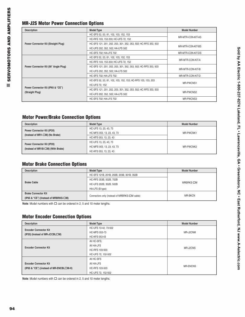
94
n
SE
RV
OM
OT
OR
S A
ND
AM
PL
IFIE
RS
Note: Model numbers with o
can be ordered in 2, 5 and 10 meter lengths.
Description Model Type Model Number
HC-SFS 52, 53, 81, 102, 103, 152, 153
HC-RFS 103, 153 203; HC-UFS 72, 152MR-MTR-CON-KIT-AS
Power Connector Kit (Straight Plug) HC-SFS 121, 201, 202, 203, 301, 352, 353, 502; HC-RFS 353, 503
HC-UFS 202, 352, 502; HA-LFS 502MR-MTR-CON-KIT-BS
HC-SFS 702; HA-LFS 702 MR-MTR-CON-KIT-DS
HC-SFS 52, 53, 81, 102, 103, 152, 153
HC-RFS 103, 153 203; HC-UFS 72, 152MR-MTR-CON-KIT-A
Power Connector Kit (90° Angle Plug) HC-SFS 121, 201, 202, 203, 301, 352, 353, 502; HC-RFS 353, 503
HC-UFS 202, 352, 502; HA-LFS 502MR-MTR-CON-KIT-B
HC-SFS 702; HA-LFS 702 MR-MTR-CON-KIT-D
HC-SFS 52, 53, 81, 102, 103, 152, 153; HC-RFS 103, 153, 203
HC-UFS 72, 152MR-PWCNS1
Power Connector Kit (IP65 & “CE”)HC-SFS 121, 201, 202, 203, 301, 352, 353, 502; HC-RFS 353, 503
(Straight Plug)HC-UFS 202, 352, 502; HA-LFS 502
MR-PWCNS2
HC-SFS 702; HA-LFS 702 MR-PWCNS3
MR-J2S Motor Power Connection Options
Description Model Type Model Number
Power Connector Kit (IP20) HC-UFS 13, 23, 43, 73
(Instead of MR1-o
M) (No Brake)HC-MFS 053, 13, 23, 43, 73 MR-PWCNK1
HC-KFS 053, 13, 23, 43
Power Connector Kit (IP20) HC-UFS 13, 23, 43, 73
(Instead of MR1B-o
M) (With Brake)HC-MFS 053, 13, 23, 43, 73 MR-PWCNK2
HC-KFS 053, 13, 23, 43
Motor Power/Brake Connection Options
Description Model Type Model Number
HC-SFS 121B, 201B, 202B, 203B, 301B, 352B
Brake CableHC-RFS 353B, 502B, 702B
HC-UFS 202B, 352B, 502B MRBRKS-o
M
HA-LFS (B type)
Brake Connector Kit Connectors only (instead of MRBRKS-o
M cable)(IP65 & “CE”) (Instead of MRBRKS-o
M)MR-BKCN
Motor Brake Connection Options
Description Model Type Model Number
Encoder Connector Kit HC-UFS 13-42, 73-502
(IP20) (Instead of MR-JCCBLo
M)HC-MFS 053-73 MR-J2CNM
HC-KFS 053-43
All HC-SFS;
Encoder Connector KitAll HA-LFS
HC-RFS 103-503MR-J2CNS
HC-UFS 72, 152-502
All HC-SFS
Encoder Connector Kit All HA-LFS
(IP65 & “CE”) (instead of MR-ENCBLo
M-H) HC-RFS 103-503MR-ENCNS
HC-UFS 72, 152-502
Motor Encoder Connection Options
Note: Model numbers with o
can be ordered in 2, 5 and 10 meter lengths.
Sold by AA
Electric 1-800-237-8274 Lakeland, FL • Lawrenceville, G
A • G
reensboro, NC
• East Rutherford, N
J ww
w.A
-Aelectric.com
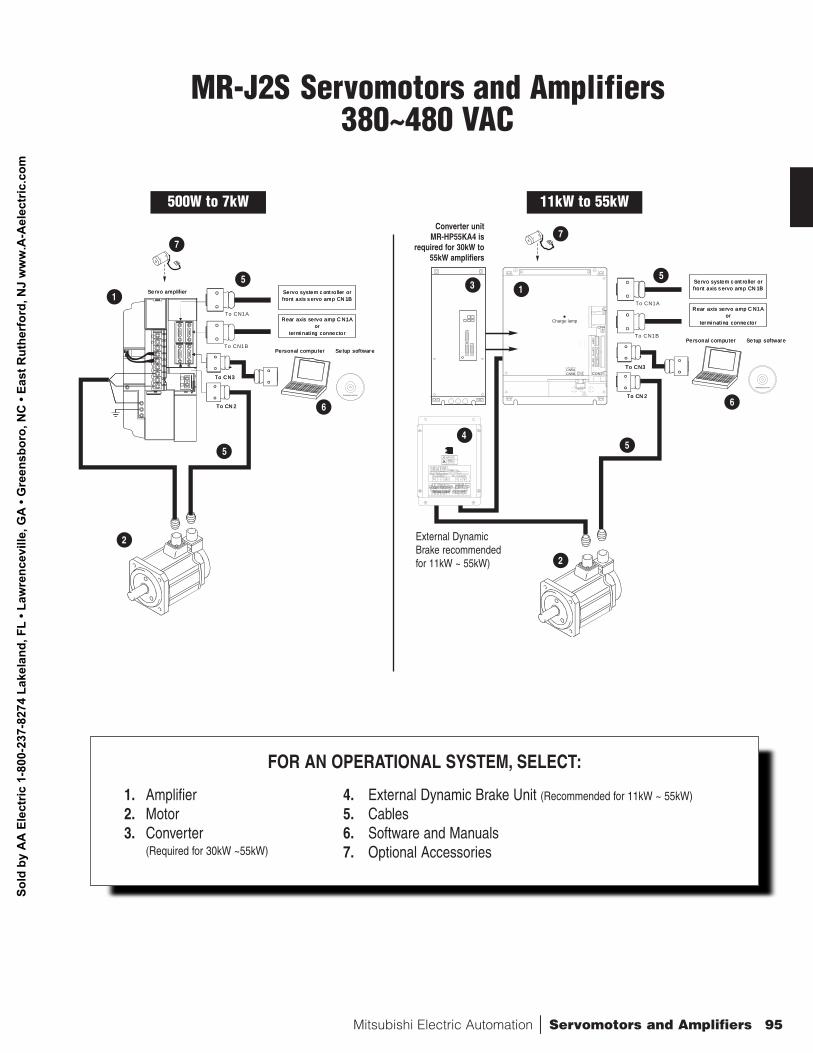
Mitsubishi Electric Automation | Servomotors and Amplifiers 95
MR-J2S Servomotors and Amplifiers380~480 VAC
FOR AN OPERATIONAL SYSTEM, SELECT:
1. Amplifier 4. External Dynamic Brake Unit (Recommended for 11kW ~ 55kW)
2. Motor 5. Cables3. Converter 6. Software and Manuals
(Required for 30kW ~55kW) 7. Optional Accessories
Se rvo system c ont ro ller orfront axis s ervo amp CN 1B
Rear axis servo amp C N1Aor
terminat ing connector
To CN3
To CN1A
To CN 2
Pe rsonal compu ter Se tup software
Se rvo system c ont ro ller orfront axis s ervo amp CN 1B
Rear axis servo amp C N1Aor
terminat ing connector
To CN3
To CN1B
To CN 2
Pe rsonal compu ter Se tup software
CN2CN5ACN5B CON2
CN1B
CN1A
CN3
CN4Charge lamp
CN2CN5ACN5B CON2
CN1B
CN1A
CN3
CN4Charge lamp
Se rvo system c ont ro ller orfront axis s ervo amp CN 1B
Rear axis servo amp C N1Aor
terminat ing connector
To CN3
To CN1A
To CN 2
Pe rsonal compu ter Se tup software
Se rvo amplif ier Se rvo system c ont ro ller orfront axis s ervo amp CN 1B
Rear axis servo amp C N1Aor
terminat ing connector
To CN3
To CN1B
To CN 2
Pe rsonal compu ter Se tup software
Se rvo amplif ier 13
4
5
5
5
1
2
2
66
77
5
Converter unit MR-HP55KA4 is
required for 30kW to55kW amplifiers
External DynamicBrake recommendedfor 11kW ~ 55kW)
500W to 7kW 11kW to 55kW
Sold
by
AA
Ele
ctric
1-8
00-2
37-8
274
Lake
land
, FL
• Law
renc
evill
e, G
A •
Gre
ensb
oro,
NC
• Ea
st R
uthe
rfor
d, N
J w
ww
.A-A
elec
tric
.com
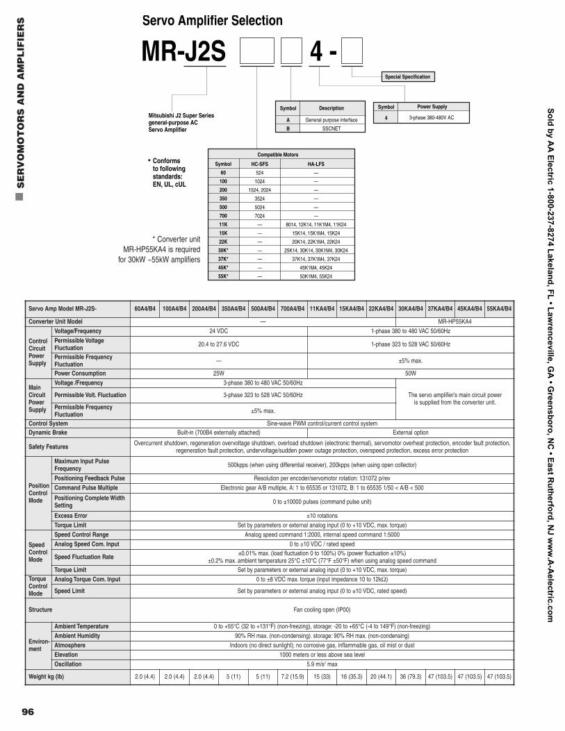
96
n
SE
RV
OM
OT
OR
S A
ND
AM
PL
IFIE
RS
131072 pulse p/revencoder for use in absolute andincremental systems (serial encoder)
HC-SFS 4Servomotor Selection
Symbol
4Description
400V Class
Symbol52
102
152
202
352
502
702
Rated Output Capacity kW
0.5
1.0
1.5
2.0
3.5
5.0
7.0
Symbol
None
B
ElectromagneticBrake
None
Installed
Symbol
None
K
Shaft
Straight Shaft
Keyway (Standard)
MR-HP55KA4 Required for the 30kW~55kW Amplifiers
Converter Selection:
Conforms to following standards: EN, UL, cUL
Conforms to following standards: EN, UL, cUL
Mitsubishi J2 Super Seriesgeneral-purpose AC Servo Amplifier
MR-J2S 4 - Servo Amplifier Selection
Symbol
60
100
200
350
500
700
11K
15K
22K
30K*
37K*
45K*
55K*
HC-SFS
524
1024
1524, 2024
3524
5024
7024
—
—
—
—
—
—
—
HA-LFS
—
—
—
—
—
—
8014, 12K14, 11K1M4, 11K24
15K14, 15K1M4, 15K24
20K14, 22K1M4, 22K24
25K14, 30K14, 30K1M4, 30K24
37K14, 37K1M4, 37K24
45K1M4, 45K24
50K1M4, 55K24
Symbol
1
1M
2
Rated Speed (r/min)
1000
1500
2000
Symbol
A
B
Description
General purpose interface
SSCNET
Symbol
4
Power Supply
3-phase 380-480V AC
* The HA-LFS 1000 r/min 8.0 to 25 kW capacities are special-order products
Special Specification
Compatible Motors
Servo Amp Model MR-J2S- 60A4/B4 100A4/B4 200A4/B4 350A4/B4 500A4/B4 700A4/B4 11KA4/B4 15KA4/B4 22KA4/B4 30KA4/B4 37KA4/B4 45KA4/B4 55KA4/B4
Converter Unit Model — MR-HP55KA4
ControlCircuitPowerSupply
Voltage/Frequency 24 VDC 1-phase 380 to 480 VAC 50/60Hz
Permissible VoltageFluctuation 20.4 to 27.6 VDC 1-phase 323 to 528 VAC 50/60Hz
Permissible FrequencyFluctuation — ±5% max.
Power Consumption 25W 50W
MainCircuitPowerSupply
Voltage /Frequency 3-phase 380 to 480 VAC 50/60Hz
The servo amplifier’s main circuit poweris supplied from the converter unit.
Permissible Volt. Fluctuation 3-phase 323 to 528 VAC 50/60Hz
Permissible FrequencyFluctuation ±5% max.
Control System Sine-wave PWM control/current control systemDynamic Brake Built-in (700B4 externally attached) External option
Safety Features Overcurrent shutdown, regeneration overvoltage shutdown, overload shutdown (electronic thermal), servomotor overheat protection, encoder fault protection,regeneration fault protection, undervoltage/sudden power outage protection, overspeed protection, excess error protection
PositionControlMode
Maximum Input PulseFrequency 500kpps (when using differential receiver), 200kpps (when using open collector)
Positioning Feedback Pulse Resolution per encoder/servomotor rotation: 131072 p/rev
Command Pulse Multiple Electronic gear A/B multiple, A: 1 to 65535 or 131072, B: 1 to 65535 1/50 < A/B < 500
Positioning Complete WidthSetting 0 to ±10000 pulses (command pulse unit)
Excess Error ±10 rotations
Torque Limit Set by parameters or external analog input (0 to +10 VDC, max. torque)
SpeedControlMode
Speed Control Range Analog speed command 1:2000, internal speed command 1:5000
Analog Speed Com. Input 0 to ±10 VDC / rated speed
Speed Fluctuation Rate ±0.01% max. (load fluctuation 0 to 100%) 0% (power fluctuation ±10%)±0.2% max. ambient temperature 25°C ±10°C (77°F ±50°F) when using analog speed command
Torque Limit Set by parameters or external analog input (0 to +10 VDC, max. torque)TorqueControlMode
Analog Torque Com. Input 0 to ±8 VDC max. torque (input impedance 10 to 12kΩ)
Speed Limit Set by parameters or external analog input (0 to ±10 VDC, rated speed)
Structure Fan cooling open (IP00)
Environ-ment
Ambient Temperature 0 to +55°C (32 to +131°F) (non-freezing), storage: -20 to +65°C (-4 to 149°F) (non-freezing)
Ambient Humidity 90% RH max. (non-condensing). storage: 90% RH max. (non-condensing)
Atmosphere Indoors (no direct sunlight); no corrosive gas, inflammable gas, oil mist or dust
Elevation 1000 meters or less above sea level
Oscillation 5.9 m/s2 max
Weight kg (lb) 2.0 (4.4) 2.0 (4.4) 2.0 (4.4) 5 (11) 5 (11) 7.2 (15.9) 15 (33) 16 (35.3) 20 (44.1) 36 (79.3) 47 (103.5) 47 (103.5) 47 (103.5)
* Converter unit MR-HP55KA4 is required
for 30kW ~55kW amplifiers
Sold by AA
Electric 1-800-237-8274 Lakeland, FL • Lawrenceville, G
A • G
reensboro, NC
• East Rutherford, N
J ww
w.A
-Aelectric.com
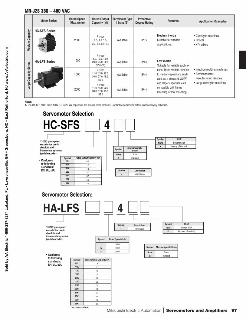
Mitsubishi Electric Automation | Servomotors and Amplifiers 97
MR-J2S 380 – 480 VAC
Motor Series Rated Speed(Max. r/min)
Rated OutputCapacity (kW)
Servomotor Type/ Brake (B)
ProtectiveDegree Rating Features Application Examples
HC-SFS Series• Conveyor machines• Robots• X-Y tables
Medium inertiaSuitable for variableapplications.
IP65Available7 types
0.5, 1.0, 1.5,2.0, 3.5, 5.0, 7.0
2000
• Injection molding machines• Semiconductor
manufacturing devices• Large conveyor machines
Low inertiaSuitable for variable applica-tions. Three models from lowto medium-speed are avail-able. As a standard, 30kWand larger capabilities arecompatible with flangemounting or foot mounting.
IP44
IP44
IP44
Available
Available
Available
7 types8.0, 12.0, 15.0,20.0, 25.0, 30.0,
37.0 (*1)
7 types11.0, 15.0, 22.0,30.0, 37.0, 45.0,
50.0
7 types11.0, 15.0, 22.0,30.0, 37.0, 45.0,
55.0
1000
2000
1500
Notes:1. The HA-LFS 1000 r/min 400V 8.0 to 25 kW capacities are special order products. Contact Mitsubishi for details on the delivery schedule.
Med
ium
Cap
acity
HA-LFS Series
Larg
e Ca
paci
ty S
erie
s
131072 pulse p/revencoder for use in absolute andincremental systems (serial encoder)
HC-SFS 4Servomotor Selection
Symbol
4Description
400V Class
Symbol52
102
152
202
352
502
702
Rated Output Capacity kW
0.5
1.0
1.5
2.0
3.5
5.0
7.0
Symbol
None
B
ElectromagneticBrake
None
Installed
Symbol
None
K
Shaft
Straight Shaft
Keyway (Standard)
MR-HP55KA4 Required for the 30kW~55kW Amplifiers
Converter Selection:
Conforms to following standards: EN, UL, cUL
Conforms to following standards: EN, UL, cUL
Mitsubishi J2 Super Seriesgeneral-purpose AC Servo Amplifier
MR-J2S 4 - Servo Amplifier Selection
Symbol
60
100
200
350
500
700
11K
15K
22K
30K*
37K*
45K*
55K*
HC-SFS
524
1024
1524, 2024
3524
5024
7024
—
—
—
—
—
—
—
HA-LFS
—
—
—
—
—
—
8014, 12K14, 11K1M4, 11K24
15K14, 15K1M4, 15K24
20K14, 22K1M4, 22K24
25K14, 30K14, 30K1M4, 30K24
37K14, 37K1M4, 37K24
45K1M4, 45K24
50K1M4, 55K24
Symbol
1
1M
2
Rated Speed (r/min)
1000
1500
2000
Symbol
A
B
Description
General purpose interface
SSCNET
Symbol
4
Power Supply
3-phase 380-480V AC
* The HA-LFS 1000 r/min 8.0 to 25 kW capacities are special-order products
Special Specification
Compatible Motors
Sold
by
AA
Ele
ctric
1-8
00-2
37-8
274
Lake
land
, FL
• Law
renc
evill
e, G
A •
Gre
ensb
oro,
NC
• Ea
st R
uthe
rfor
d, N
J w
ww
.A-A
elec
tric
.com
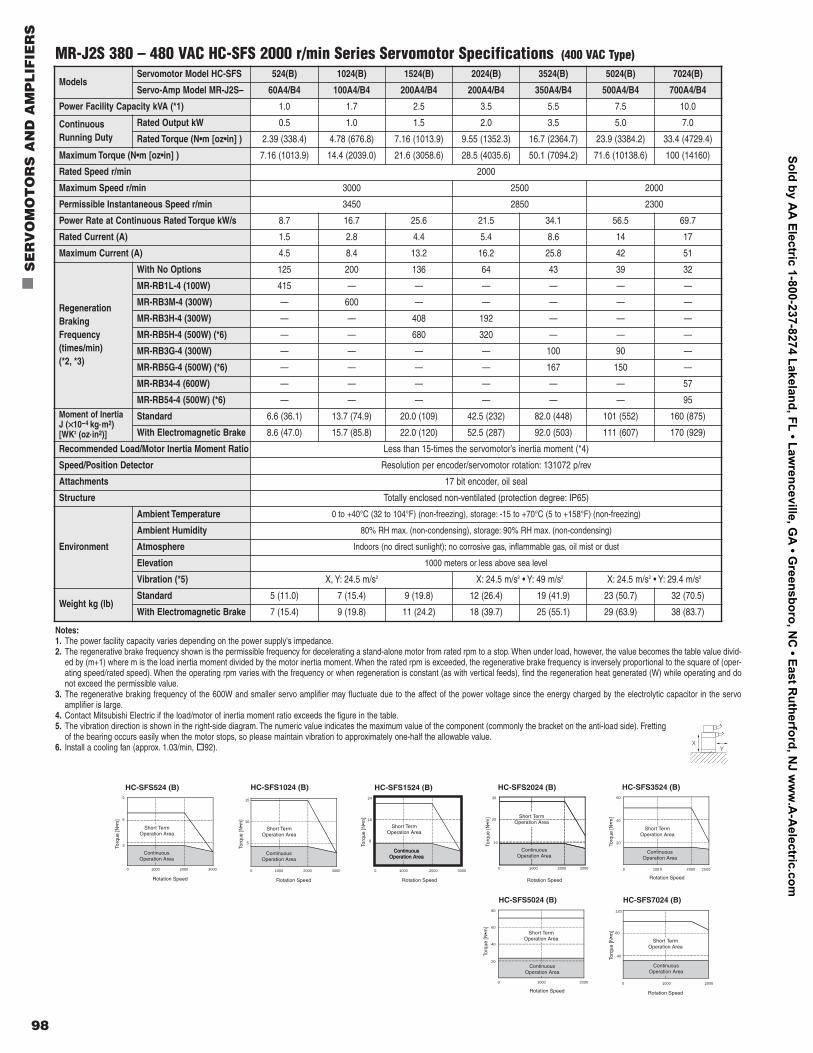
98
n
SE
RV
OM
OT
OR
S A
ND
AM
PL
IFIE
RS
ModelsServomotor Model HC-SFS 524(B) 1024(B) 1524(B) 2024(B) 3524(B) 5024(B) 7024(B)
Servo-Amp Model MR-J2S– 60A4/B4 100A4/B4 200A4/B4 200A4/B4 350A4/B4 500A4/B4 700A4/B4
Power Facility Capacity kVA (*1) 1.0 1.7 2.5 3.5 5.5 7.5 10.0
ContinuousRunning Duty
Rated Output kW 0.5 1.0 1.5 2.0 3.5 5.0 7.0
Rated Torque (N•m [oz•in] ) 2.39 (338.4) 4.78 (676.8) 7.16 (1013.9) 9.55 (1352.3) 16.7 (2364.7) 23.9 (3384.2) 33.4 (4729.4)
Maximum Torque (N•m [oz•in] ) 7.16 (1013.9) 14.4 (2039.0) 21.6 (3058.6) 28.5 (4035.6) 50.1 (7094.2) 71.6 (10138.6) 100 (14160)
Rated Speed r/min 2000
Maximum Speed r/min 3000 2500 2000
Permissible Instantaneous Speed r/min 3450 2850 2300
Power Rate at Continuous Rated Torque kW/s 8.7 16.7 25.6 21.5 34.1 56.5 69.7
Rated Current (A) 1.5 2.8 4.4 5.4 8.6 14 17
Maximum Current (A) 4.5 8.4 13.2 16.2 25.8 42 51
RegenerationBrakingFrequency(times/min) (*2, *3)
With No Options 125 200 136 64 43 39 32
MR-RB1L-4 (100W) 415 — — — — — —
MR-RB3M-4 (300W) — 600 — — — — —
MR-RB3H-4 (300W) — — 408 192 — — —
MR-RB5H-4 (500W) (*6) — — 680 320 — — —
MR-RB3G-4 (300W) — — — — 100 90 —
MR-RB5G-4 (500W) (*6) — — — — 167 150 —
MR-RB34-4 (600W) — — — — — — 57
MR-RB54-4 (500W) (*6) — — — — — — 95Moment of InertiaJ (××10-4 kg.m2) [WK2 (oz.in2)]
Standard 6.6 (36.1) 13.7 (74.9) 20.0 (109) 42.5 (232) 82.0 (448) 101 (552) 160 (875)
With Electromagnetic Brake 8.6 (47.0) 15.7 (85.8) 22.0 (120) 52.5 (287) 92.0 (503) 111 (607) 170 (929)
Recommended Load/Motor Inertia Moment Ratio Less than 15-times the servomotor’s inertia moment (*4)
Speed/Position Detector Resolution per encoder/servomotor rotation: 131072 p/rev
Attachments 17 bit encoder, oil seal
Structure Totally enclosed non-ventilated (protection degree: IP65)
Environment
Ambient Temperature 0 to +40°C (32 to 104°F) (non-freezing), storage: -15 to +70°C (5 to +158°F) (non-freezing)
Ambient Humidity 80% RH max. (non-condensing), storage: 90% RH max. (non-condensing)
Atmosphere Indoors (no direct sunlight); no corrosive gas, inflammable gas, oil mist or dust
Elevation 1000 meters or less above sea level
Vibration (*5) X, Y: 24.5 m/s2 X: 24.5 m/s2 • Y: 49 m/s2 X: 24.5 m/s2 • Y: 29.4 m/s2
Weight kg (lb)Standard 5 (11.0) 7 (15.4) 9 (19.8) 12 (26.4) 19 (41.9) 23 (50.7) 32 (70.5)
With Electromagnetic Brake 7 (15.4) 9 (19.8) 11 (24.2) 18 (39.7) 25 (55.1) 29 (63.9) 38 (83.7)
Notes:1. The power facility capacity varies depending on the power supply's impedance.2. The regenerative brake frequency shown is the permissible frequency for decelerating a stand-alone motor from rated rpm to a stop. When under load, however, the value becomes the table value divid-
ed by (m+1) where m is the load inertia moment divided by the motor inertia moment. When the rated rpm is exceeded, the regenerative brake frequency is inversely proportional to the square of (oper-ating speed/rated speed). When the operating rpm varies with the frequency or when regeneration is constant (as with vertical feeds), find the regeneration heat generated (W) while operating and donot exceed the permissible value.
3. The regenerative braking frequency of the 600W and smaller servo amplifier may fluctuate due to the affect of the power voltage since the energy charged by the electrolytic capacitor in the servo amplifier is large.
4. Contact Mitsubishi Electric if the load/motor of inertia moment ratio exceeds the figure in the table.5. The vibration direction is shown in the right-side diagram. The numeric value indicates the maximum value of the component (commonly the bracket on the anti-load side). Fretting
of the bearing occurs easily when the motor stops, so please maintain vibration to approximately one-half the allowable value.6. Install a cooling fan (approx. 1.03/min, o
92). XY
MR-J2S 380 – 480 VAC HC-SFS 2000 r/min Series Servomotor Specifications (400 VAC Type)
0 100 0 2000 2500
60
40
20
Rotation Speed
Torq
ue [N
•m]
ContinuousOperation Area
Short TermOperation Area
HC-SFS3524 (B)
Rotation Speed
Torq
ue [N
•m]
HC-SFS5024 (B)
80
60
40
20
0 1000 2000
Short TermOperation Area
ContinuousOperation Area
HC-SFS524 (B)
Rotation Speed
Torq
ue [N
•m]
9
6
3
0 1000 2000 3000
ContinuousOperation Area
Short TermOperation Area
HC-SFS1024 (B)
Torq
ue [N
•m]
15
10
5
Rotation Speed
0 1000 2000 3000
Short TermOperation Area
ContinuousOperation Area
HC-SFS1524 (B)
Torq
ue [N
•m]
24
16
8
Rotation Speed Rotation Speed
0 1000 2000 3000
Short TermOperation Area
ContinuousOperation Area
ContinuousOperation Area
HC-SFS2024 (B)
Torq
ue [N
•m]
30
20
10
0 1000 2000 3000
ContinuousOperation Area
Short TermOperation Area
HC-SFS7024 (B)
Torq
ue [N
•m]
120
80
40
Rotation Speed
0 1000 2000
Short TermOperation Area
ContinuousOperation Area
Sold by AA
Electric 1-800-237-8274 Lakeland, FL • Lawrenceville, G
A • G
reensboro, NC
• East Rutherford, N
J ww
w.A
-Aelectric.com
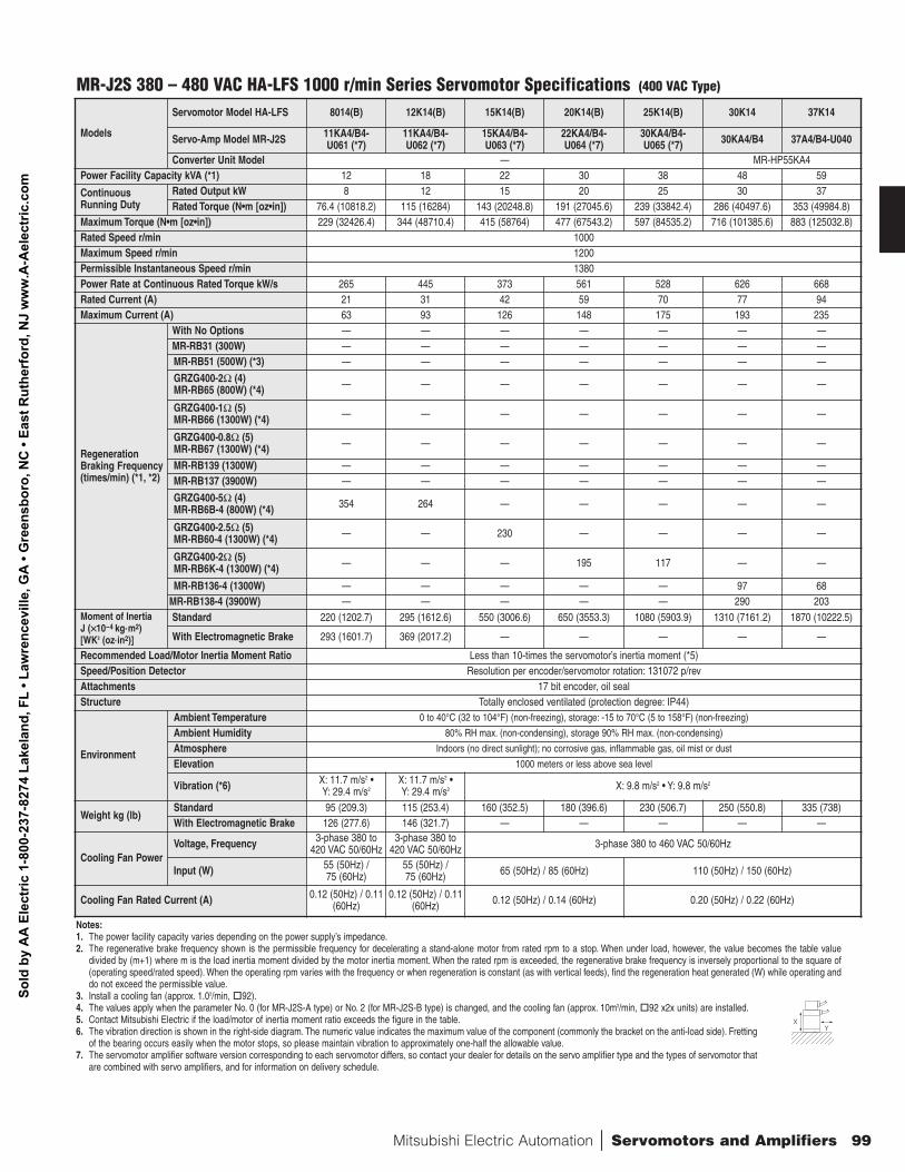
Mitsubishi Electric Automation | Servomotors and Amplifiers 99
Models
Servomotor Model HA-LFS 8014(B) 12K14(B) 15K14(B) 20K14(B) 25K14(B) 30K14 37K14
Servo-Amp Model MR-J2S 11KA4/B4-U061 (*7)
11KA4/B4-U062 (*7)
15KA4/B4-U063 (*7)
22KA4/B4-U064 (*7)
30KA4/B4-U065 (*7) 30KA4/B4 37A4/B4-U040
Converter Unit Model — MR-HP55KA4Power Facility Capacity kVA (*1) 12 18 22 30 38 48 59
ContinuousRunning Duty
Rated Output kW 8 12 15 20 25 30 37Rated Torque (N•m [oz•in]) 76.4 (10818.2) 115 (16284) 143 (20248.8) 191 (27045.6) 239 (33842.4) 286 (40497.6) 353 (49984.8)
Maximum Torque (N•m [oz•in]) 229 (32426.4) 344 (48710.4) 415 (58764) 477 (67543.2) 597 (84535.2) 716 (101385.6) 883 (125032.8)Rated Speed r/min 1000Maximum Speed r/min 1200Permissible Instantaneous Speed r/min 1380Power Rate at Continuous Rated Torque kW/s 265 445 373 561 528 626 668Rated Current (A) 21 31 42 59 70 77 94Maximum Current (A) 63 93 126 148 175 193 235
RegenerationBraking Frequency(times/min) (*1, *2)
With No Options — — — — — — —MR-RB31 (300W) — — — — — — —MR-RB51 (500W) (*3) — — — — — — —
GRZG400-2Ω (4)MR-RB65 (800W) (*4) — — — — — — —
GRZG400-1Ω (5)MR-RB66 (1300W) (*4) — — — — — — —
GRZG400-0.8Ω (5)MR-RB67 (1300W) (*4) — — — — — — —
MR-RB139 (1300W) — — — — — — —MR-RB137 (3900W) — — — — — — —
GRZG400-5Ω (4)MR-RB6B-4 (800W) (*4) 354 264 — — — — —
GRZG400-2.5Ω (5)MR-RB60-4 (1300W) (*4) — — 230 — — — —
GRZG400-2Ω (5)MR-RB6K-4 (1300W) (*4) — — — 195 117 — —
MR-RB136-4 (1300W) — — — — — 97 68MR-RB138-4 (3900W) — — — — — 290 203
Moment of InertiaJ (××10-4 kg.m2) [WK2 (oz.in2)]
Standard 220 (1202.7) 295 (1612.6) 550 (3006.6) 650 (3553.3) 1080 (5903.9) 1310 (7161.2) 1870 (10222.5)
With Electromagnetic Brake 293 (1601.7) 369 (2017.2) — — — — —
Recommended Load/Motor Inertia Moment Ratio Less than 10-times the servomotor’s inertia moment (*5)Speed/Position Detector Resolution per encoder/servomotor rotation: 131072 p/revAttachments 17 bit encoder, oil sealStructure Totally enclosed ventilated (protection degree: IP44)
Environment
Ambient Temperature 0 to 40°C (32 to 104°F) (non-freezing), storage: -15 to 70°C (5 to 158°F) (non-freezing)
Ambient Humidity 80% RH max. (non-condensing), storage 90% RH max. (non-condensing)
Atmosphere Indoors (no direct sunlight); no corrosive gas, inflammable gas, oil mist or dust
Elevation 1000 meters or less above sea level
Vibration (*6) X: 11.7 m/s2 • Y: 29.4 m/s2
X: 11.7 m/s2 • Y: 29.4 m/s2 X: 9.8 m/s2 • Y: 9.8 m/s2
Weight kg (lb)Standard 95 (209.3) 115 (253.4) 160 (352.5) 180 (396.6) 230 (506.7) 250 (550.8) 335 (738)With Electromagnetic Brake 126 (277.6) 146 (321.7) — — — — —
Cooling Fan PowerVoltage, Frequency 3-phase 380 to
420 VAC 50/60Hz3-phase 380 to
420 VAC 50/60Hz 3-phase 380 to 460 VAC 50/60Hz
Input (W) 55 (50Hz) / 75 (60Hz)
55 (50Hz) / 75 (60Hz) 65 (50Hz) / 85 (60Hz) 110 (50Hz) / 150 (60Hz)
Cooling Fan Rated Current (A) 0.12 (50Hz) / 0.11(60Hz)
0.12 (50Hz) / 0.11(60Hz) 0.12 (50Hz) / 0.14 (60Hz) 0.20 (50Hz) / 0.22 (60Hz)
Notes:1. The power facility capacity varies depending on the power supply’s impedance.2. The regenerative brake frequency shown is the permissible frequency for decelerating a stand-alone motor from rated rpm to a stop. When under load, however, the value becomes the table value
divided by (m+1) where m is the load inertia moment divided by the motor inertia moment. When the rated rpm is exceeded, the regenerative brake frequency is inversely proportional to the square of(operating speed/rated speed). When the operating rpm varies with the frequency or when regeneration is constant (as with vertical feeds), find the regeneration heat generated (W) while operating anddo not exceed the permissible value.
3. Install a cooling fan (approx. 1.03/min, o
92).4. The values apply when the parameter No. 0 (for MR-J2S-A type) or No. 2 (for MR-J2S-B type) is changed, and the cooling fan (approx. 10m3/min, o
92 x2x units) are installed.5. Contact Mitsubishi Electric if the load/motor of inertia moment ratio exceeds the figure in the table.6. The vibration direction is shown in the right-side diagram. The numeric value indicates the maximum value of the component (commonly the bracket on the anti-load side). Fretting
of the bearing occurs easily when the motor stops, so please maintain vibration to approximately one-half the allowable value.7. The servomotor amplifier software version corresponding to each servomotor differs, so contact your dealer for details on the servo amplifier type and the types of servomotor that
are combined with servo amplifiers, and for information on delivery schedule.
MR-J2S 380 – 480 VAC HA-LFS 1000 r/min Series Servomotor Specifications (400 VAC Type)
XY
Sold
by
AA
Ele
ctric
1-8
00-2
37-8
274
Lake
land
, FL
• Law
renc
evill
e, G
A •
Gre
ensb
oro,
NC
• Ea
st R
uthe
rfor
d, N
J w
ww
.A-A
elec
tric
.com
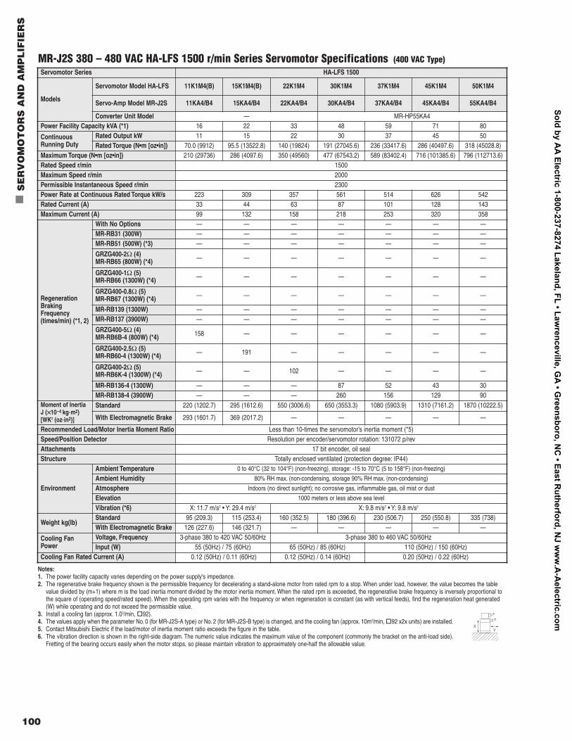
100
n
SE
RV
OM
OT
OR
S A
ND
AM
PL
IFIE
RS
Servomotor Series HA-LFS 1500
Models
Servomotor Model HA-LFS 11K1M4(B) 15K1M4(B) 22K1M4 30K1M4 37K1M4 45K1M4 50K1M4
Servo-Amp Model MR-J2S 11KA4/B4 15KA4/B4 22KA4/B4 30KA4/B4 37KA4/B4 45KA4/B4 55KA4/B4
Converter Unit Model — MR-HP55KA4 Power Facility Capacity kVA (*1) 16 22 33 48 59 71 80
ContinuousRunning Duty
Rated Output kW 11 15 22 30 37 45 50Rated Torque (N•m [oz•in]) 70.0 (9912) 95.5 (13522.8) 140 (19824) 191 (27045.6) 236 (33417.6) 286 (40497.6) 318 (45028.8)
Maximum Torque (N•m [oz•in]) 210 (29736) 286 (4097.6) 350 (49560) 477 (67543.2) 589 (83402.4) 716 (101385.6) 796 (112713.6)Rated Speed r/min 1500Maximum Speed r/min 2000Permissible Instantaneous Speed r/min 2300Power Rate at Continuous Rated Torque kW/s 223 309 357 561 514 626 542Rated Current (A) 33 44 63 87 101 128 143Maximum Current (A) 99 132 158 218 253 320 358
RegenerationBrakingFrequency(times/min) (*1, 2)
With No Options — — — — — — —MR-RB31 (300W) — — — — — — —MR-RB51 (500W) (*3) — — — — — — —
GRZG400-2Ω (4)MR-RB65 (800W) (*4) — — — — — — —
GRZG400-1Ω (5)MR-RB66 (1300W) (*4) — — — — — — —
GRZG400-0.8Ω (5)MR-RB67 (1300W) (*4) — — — — — — —
MR-RB139 (1300W) — — — — — — —MR-RB137 (3900W) — — — — — — —
GRZG400-5Ω (4)MR-RB6B-4 (800W) (*4) 158 — — — — — —
GRZG400-2.5Ω (5)MR-RB60-4 (1300W) (*4) — 191 — — — — —
GRZG400-2Ω (5)MR-RB6K-4 (1300W) (*4) — — 102 — — — —
MR-RB136-4 (1300W) — — — 87 52 43 30MR-RB138-4 (3900W) — — — 260 156 129 90
Moment of InertiaJ (××10-4 kg.m2) [WK2 (oz.in2)]
Standard 220 (1202.7) 295 (1612.6) 550 (3006.6) 650 (3553.3) 1080 (5903.9) 1310 (7161.2) 1870 (10222.5)
With Electromagnetic Brake 293 (1601.7) 369 (2017.2) — — — — —
Recommended Load/Motor Inertia Moment Ratio Less than 10-times the servomotor’s inertia moment (*5)Speed/Position Detector Resolution per encoder/servomotor rotation: 131072 p/revAttachments 17 bit encoder, oil sealStructure Totally enclosed ventilated (protection degree: IP44)
Environment
Ambient Temperature 0 to 40°C (32 to 104°F) (non-freezing), storage: -15 to 70°C (5 to 158°F) (non-freezing)
Ambient Humidity 80% RH max. (non-condensing, storage 90% RH max. (non-condensing)
Atmosphere Indoors (no direct sunlight); no corrosive gas, inflammable gas, oil mist or dust
Elevation 1000 meters or less above sea level
Vibration (*6) X: 11.7 m/s2 • Y: 29.4 m/s2 X: 9.8 m/s2 • Y: 9.8 m/s2
Weight kg(lb)Standard 95 (209.3) 115 (253.4) 160 (352.5) 180 (396.6) 230 (506.7) 250 (550.8) 335 (738)With Electromagnetic Brake 126 (227.6) 146 (321.7) — — — — —
Cooling FanPower
Voltage, Frequency 3-phase 380 to 420 VAC 50/60Hz 3-phase 380 to 460 VAC 50/60HzInput (W) 55 (50Hz) / 75 (60Hz) 65 (50Hz) / 85 (60Hz) 110 (50Hz) / 150 (60Hz)
Cooling Fan Rated Current (A) 0.12 (50Hz) / 0.11 (60Hz) 0.12 (50Hz) / 0.14 (60Hz) 0.20 (50Hz) / 0.22 (60Hz)
Notes:1. The power facility capacity varies depending on the power supply's impedance.2. The regenerative brake frequency shown is the permissible frequency for decelerating a stand-alone motor from rated rpm to a stop. When under load, however, the value becomes the table
value divided by (m+1) where m is the load inertia moment divided by the motor inertia moment. When the rated rpm is exceeded, the regenerative brake frequency is inversely proportional tothe square of (operating speed/rated speed). When the operating rpm varies with the frequency or when regeneration is constant (as with vertical feeds), find the regeneration heat generated(W) while operating and do not exceed the permissible value.
3. Install a cooling fan (approx. 1.03/min, o
92).4. The values apply when the parameter No. 0 (for MR-J2S-A type) or No. 2 (for MR-J2S-B type) is changed, and the cooling fan (approx. 10m3/min, o
92 x2x units) are installed.5. Contact Mitsubishi Electric if the load/motor of inertia moment ratio exceeds the figure in the table.6. The vibration direction is shown in the right-side diagram. The numeric value indicates the maximum value of the component (commonly the bracket on the anti-load side).
Fretting of the bearing occurs easily when the motor stops, so please maintain vibration to approximately one-half the allowable value.
XY
MR-J2S 380 – 480 VAC HA-LFS 1500 r/min Series Servomotor Specifications (400 VAC Type)
Sold by AA
Electric 1-800-237-8274 Lakeland, FL • Lawrenceville, G
A • G
reensboro, NC
• East Rutherford, N
J ww
w.A
-Aelectric.com
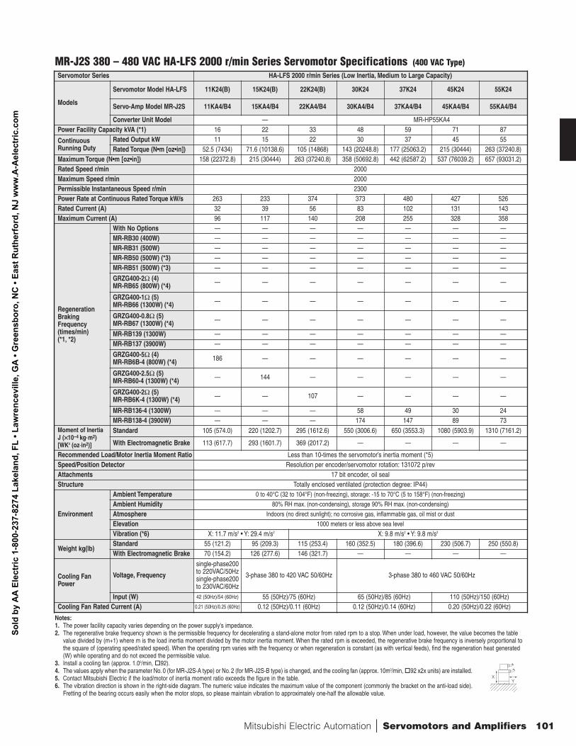
Mitsubishi Electric Automation | Servomotors and Amplifiers 101
Servomotor Series HA-LFS 2000 r/min Series (Low Inertia, Medium to Large Capacity)
Models
Servomotor Model HA-LFS 11K24(B) 15K24(B) 22K24(B) 30K24 37K24 45K24 55K24
Servo-Amp Model MR-J2S 11KA4/B4 15KA4/B4 22KA4/B4 30KA4/B4 37KA4/B4 45KA4/B4 55KA4/B4
Converter Unit Model — MR-HP55KA4 Power Facility Capacity kVA (*1) 16 22 33 48 59 71 87
ContinuousRunning Duty
Rated Output kW 11 15 22 30 37 45 55Rated Torque (N•m [oz•in]) 52.5 (7434) 71.6 (10138.6) 105 (14868) 143 (20248.8) 177 (25063.2) 215 (30444) 263 (37240.8)
Maximum Torque (N•m [oz•in]) 158 (22372.8) 215 (30444) 263 (37240.8) 358 (50692.8) 442 (62587.2) 537 (76039.2) 657 (93031.2)Rated Speed r/min 2000Maximum Speed r/min 2000Permissible Instantaneous Speed r/min 2300Power Rate at Continuous Rated Torque kW/s 263 233 374 373 480 427 526Rated Current (A) 32 39 56 83 102 131 143Maximum Current (A) 96 117 140 208 255 328 358
RegenerationBrakingFrequency(times/min) (*1, *2)
With No Options — — — — — — —MR-RB30 (400W) — — — — — — —MR-RB31 (500W) — — — — — — —MR-RB50 (500W) (*3) — — — — — — —MR-RB51 (500W) (*3) — — — — — — —
GRZG400-2Ω (4)MR-RB65 (800W) (*4) — — — — — — —
GRZG400-1Ω (5)MR-RB66 (1300W) (*4) — — — — — — —
GRZG400-0.8Ω (5)MR-RB67 (1300W) (*4) — — — — — — —
MR-RB139 (1300W) — — — — — — —MR-RB137 (3900W) — — — — — — —
GRZG400-5Ω (4)MR-RB6B-4 (800W) (*4) 186 — — — — — —
GRZG400-2.5Ω (5)MR-RB60-4 (1300W) (*4) — 144 — — — — —
GRZG400-2Ω (5)MR-RB6K-4 (1300W) (*4) — — 107 — — — —
MR-RB136-4 (1300W) — — — 58 49 30 24MR-RB138-4 (3900W) — — — 174 147 89 73
Moment of InertiaJ (××10-4 kg.m2) [WK2 (oz.in2)]
Standard 105 (574.0) 220 (1202.7) 295 (1612.6) 550 (3006.6) 650 (3553.3) 1080 (5903.9) 1310 (7161.2)
With Electromagnetic Brake 113 (617.7) 293 (1601.7) 369 (2017.2) — — — —
Recommended Load/Motor Inertia Moment Ratio Less than 10-times the servomotor’s inertia moment (*5)Speed/Position Detector Resolution per encoder/servomotor rotation: 131072 p/revAttachments 17 bit encoder, oil sealStructure Totally enclosed ventilated (protection degree: IP44)
Environment
Ambient Temperature 0 to 40°C (32 to 104°F) (non-freezing), storage: -15 to 70°C (5 to 158°F) (non-freezing)
Ambient Humidity 80% RH max. (non-condensing), storage 90% RH max. (non-condensing)
Atmosphere Indoors (no direct sunlight); no corrosive gas, inflammable gas, oil mist or dust
Elevation 1000 meters or less above sea level
Vibration (*6) X: 11.7 m/s2 • Y: 29.4 m/s2 X: 9.8 m/s2 • Y: 9.8 m/s2
Weight kg(lb)Standard 55 (121.2) 95 (209.3) 115 (253.4) 160 (352.5) 180 (396.6) 230 (506.7) 250 (550.8)With Electromagnetic Brake 70 (154.2) 126 (277.6) 146 (321.7) — — — —
Cooling FanPower
Voltage, Frequency
single-phase200to 220VAC/50Hzsingle-phase200to 230VAC/60Hz
3-phase 380 to 420 VAC 50/60Hz 3-phase 380 to 460 VAC 50/60Hz
Input (W) 42 (50Hz)/54 (60Hz) 55 (50Hz)/75 (60Hz) 65 (50Hz)/85 (60Hz) 110 (50Hz)/150 (60Hz)Cooling Fan Rated Current (A) 0.21 (50Hz)/0.25 (60Hz) 0.12 (50Hz)/0.11 (60Hz) 0.12 (50Hz)/0.14 (60Hz) 0.20 (50Hz)/0.22 (60Hz)
Notes:1. The power facility capacity varies depending on the power supply's impedance.2. The regenerative brake frequency shown is the permissible frequency for decelerating a stand-alone motor from rated rpm to a stop. When under load, however, the value becomes the table
value divided by (m+1) where m is the load inertia moment divided by the motor inertia moment. When the rated rpm is exceeded, the regenerative brake frequency is inversely proportional tothe square of (operating speed/rated speed). When the operating rpm varies with the frequency or when regeneration is constant (as with vertical feeds), find the regeneration heat generated(W) while operating and do not exceed the permissible value.
3. Install a cooling fan (approx. 1.03/min, o
92).4. The values apply when the parameter No. 0 (for MR-J2S-A type) or No. 2 (for MR-J2S-B type) is changed, and the cooling fan (approx. 10m3/min, o
92 x2x units) are installed.5. Contact Mitsubishi Electric if the load/motor of inertia moment ratio exceeds the figure in the table.6. The vibration direction is shown in the right-side diagram. The numeric value indicates the maximum value of the component (commonly the bracket on the anti-load side).
Fretting of the bearing occurs easily when the motor stops, so please maintain vibration to approximately one-half the allowable value.
XY
MR-J2S 380 – 480 VAC HA-LFS 2000 r/min Series Servomotor Specifications (400 VAC Type)
Sold
by
AA
Ele
ctric
1-8
00-2
37-8
274
Lake
land
, FL
• Law
renc
evill
e, G
A •
Gre
ensb
oro,
NC
• Ea
st R
uthe
rfor
d, N
J w
ww
.A-A
elec
tric
.com
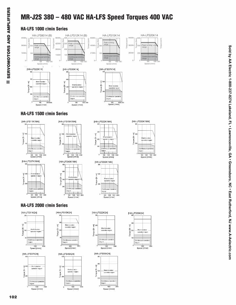
102
n
SE
RV
OM
OT
OR
S A
ND
AM
PL
IFIE
RS
MR-J2S 380 – 480 VAC HA-LFS Speed Torques 400 VAC
HA-LFS 1000 r/min Series
HA-LFS 1500 r/min Series
Speed (r/min)500 1000 1200
180
120
60
0
Speed (r/min)500 1000 1200
300
200
100
0
Speed (r/min)500 1000 1200
400
300
200
100
0
Speed (r/min)500 1000 1200
450
300
150
0
Speed (r/min)500 1000 1200
600
400
200
0
Speed (r/min)500 1000 1200
800
600
400
200
0
Speed (r/min)500 1000 1200
300
200
100
0
Speed (r/min)500 1000 1200
600
400
200
0
Speed (r/min)500 1000 1200
450
300
150
0
Speed (r/min)500 1000 1200
300
400
200
100
0
Peak running range
Continuous running range
Peak running range
Continuous running range
Peak running range
Continuous running range
Peak running range
Continuous running range
Peak running range
Continuous running range
Peak running range
Continuous running range
Peak running range
Continuous running range
Peak running range
Continuous running range
Peak running range
Continuous running range
Peak running range
Continuous running range
25200
16800
8400
0
Torq
ue (o
z•in
)
Torq
ue (N
• m)
HA-LFS601 (B) (Note 1)
84000
56000
28000
0
Torq
ue (o
z•in
)
Torq
ue (N
• m)
HA-LFS20K1 (Note 1)
42000
28000
14000
0
Torq
ue (o
z•in
)
Torq
ue (N
• m)
HA-LFS801 (B) (Note 1)56000
42000
28000
14000
0
Torq
ue (o
z•in
)
Torq
ue (N
• m)
HA-LFS12K1 (B) (Note 1)84000
56000
28000
0
Torq
ue (o
z•in
)
Torq
ue (N
• m)
HA-LFS20K14
Torq
ue (o
z•in
)42000
28000
14000
0
Torq
ue (N
• m)
HA-LFS8014 (B)56000
42000
28000
14000
0
Torq
ue (o
z•in
)
Torq
ue (N
• m)
HA-LFS12K14 (B)63000
42000
21000
0
Torq
ue (o
z•in
)
Torq
ue (N
• m)
HA-LFS15K1463000
42000
21000
0
Torq
ue (o
z•in
)
Torq
ue (N
• m)
HA-LFS15K1 (Note 1)
112000
84000
28000
56000
0
Torq
ue (o
z•in
)
Torq
ue (N
• m)
HA-LFS25K1 (Note 1)
Notes:1. Solid lines show torque characteristics for 3-phase
200VAC operation.2. Solid lines show torque characteristics for 3-phase
400VAC operation.3. The specifications are subject to change without
notice.
HA-LFS 2000 r/min Series
Sold by AA
Electric 1-800-237-8274 Lakeland, FL • Lawrenceville, G
A • G
reensboro, NC
• East Rutherford, N
J ww
w.A
-Aelectric.com
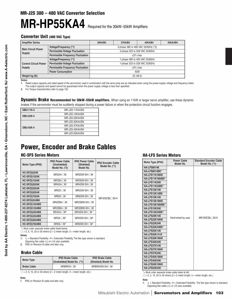
Mitsubishi Electric Automation | Servomotors and Amplifiers 103
Converter Unit (400 VAC Type)
Dynamic Brake Recommended for 30kW~55kW amplifiers. When using an 11kW or larger servo amplifier, use these dynamicbrakes if the servomotor must be suddenly stopped during a power failure or when the protection circuit function engages.
131072 pulse p/revencoder for use in absolute andincremental systems (serial encoder)
131072 pulse p/revencoder for use in absolute andincremental systems (serial encoder)
HC-SFS 4Servomotor Selection
Symbol
4Description
400V Class
Symbol
4Description
400V Class
Symbol52
102
152
202
352
502
702
Rated Output Capacity kW
0.5
1.0
1.5
2.0
3.5
5.0
7.0
Symbol
None
B
ElectromagneticBrake
None
Installed
Symbol
None
K
Shaft
Straight Shaft
Keyway (Standard)
MR-HP55KA4 Required for the 30kW~55kW Amplifiers
Converter Selection:
Conforms to following standards: EN, UL, cUL
Symbol
None
K
Shaft
Straight Shaft
Keyway (Standard)
Symbol801
11K
12K
15K
20K
22K
25K
30K*
37K*
45K*
50K*
55K*
Rated Output Capacity kW
8
11
12
15
20
22
25
30
37
45
50
55
Conforms to following standards: EN, UL, cUL
Mitsubishi general-purpose AC Servo Amplifier
MR-J2S 4 - Servo Amplifier Selection
Symbol
60
100
200
350
500
700
11K
15K
22K
30K*
37K*
45K*
55K*
HC-SFS
524
1024
1524, 2024
3524
5024
7024
—
—
—
—
—
—
—
HA-LFS
—
—
—
—
—
—
8014, 12K14, 11K1 M4, 11K24
15K14, 15K1 M 4, 15K24
20K14, 22K1 M 4, 22K24
25K14, 30K14, 30K1 M4, 30K24
37K14, 37K1 M 4, 37K24
45K1 M 4, 45K24
50K1 M 4, 55K24
Symbol
1
1M
2
Rated Speed (r/min)
1000
1500
2000
Symbol
A
B
Description
General purpose interfa ce
SSCN ET
Symbol
4
Power Supply
3-phase 380 -480V AC
* The HA-LF S 1000 r /min 8.0 to 25 kW capa cities are spe c ial - order produ cts
Special Specification
Conforms to following standards: EN, UL, cUL
HA-LFS 4Servomotor Selection:
Symbol
None
B
Electromagnetic Brake
None
Installed
Symbol
1
1M
2
Rated Speed r/min
1000
1500
2000
* No brake available
Amplifier Series 30KA/B4 37KA/B4 45KA/B4 55KA4/B4
Main Circuit PowerSupply
Voltage/Frequency (*1) 3-phase 380 to 480 VAC 50/60Hz (*2)Permissible Voltage Fluctuation 3-phase 323 to 528 VAC 50/60HzPermissible Frequency Fluctuation ±5% max.
Control Circuit PowerSupply
Voltage/Frequency (*1) 1-phase 380 to 420 VAC 50/60HzPermissible Voltage Fluctuation 1-phase 323 to 528 VAC 50/60HzPermissible Frequency Fluctuation ±5% max.Power Consumption 50W
Weight kg (lb) 22 (48.5)
DBU-11K-4 MR-J2S-11KA4/B4
DBU-22K-4MR-J2S-15KA4/B4MR-J2S-22KA4/B4
DBU-55K-4
MR-J2S-30KA4/B4MR-J2S-37KA4/B4MR-J2S-45KA4/B4MR-J2S-55KA4/B4
Power, Encoder and Brake CablesHC-SFS Series Motors
Notes:1. Rated output capacity and rated speed of the servomotor used in combination with the servo-amp are as indicated when using the power-supply voltage and frequency listed.
The output capacity and speed cannot be guaranteed when the power supply voltage is less than specified.2. For Torque characteristics refer to page 102.
Motor Type (IP65)IP65 Power Cable
(Unshielded) Model No. (*2)
IP65 Power Cable(Shielded) Model No.
IP65 Encoder CableModel No. (*1)
HC-SF(S)524KMR2S4-nnM MR2SW-SH-nnM
MR-ENCBLnnM-H
HC-SF(S)1024KHC-SF(S)1524K MR3S4-nnM MR3SW-SH-nnMHC-SF(S)2024K MR4S4-nnM MR4SW-SH-nnMHC-SF(S)3524K
MR5S-nnM MR5SW-SH-nnMHC-SF(S)5024KHC-SF(S)7024K MR6S-nnM MR6SW-SH-nnMHC-SF(S)524BK
MR2SB4-nnM MR2SBW-SH-nnMHC-SF(S)1024BKHC-SF(S)1524BK MR3SB4-nnM MR3SBW-SH-nnMHC-SF(S)2024BK MR4S4-nnM* MR4SW-SH-nnM * HC-SF(S)3524BK
MR5S-nnM* MR5SW-SH-nnM*HC-SF(S)5024BKHC-SF(S)7024BK MR6S-nnM* MR6SW-SH-nnM*
*= Must order separate brake cable listed below.nn = 2, 5, 10, 20 or 30 where (2 = 2 meter length, 5 = meter length, etc.)
HA-LFS Series MotorsMotor Type (IP44) Power Cable
Model No.Standard Encoder Cable
Model No. (*1)HA-LFS8014K
Hard-wired by user MR-ENCBLnnM-H
HA-LFS8014BK*HA-LFS11K1M4KHA-LFS11K1M4BK*HA-LFS11K24KHA-LFS11K24BK*HA-LFS12K14KHA-LFS12K14BKHA-LFS15K14KHA-LFS15K1M4KHA-LFS15K1M4BK*HA-LFS15K24KHA-LFS15K24BK*HA-LFS20K14KHA-LFS22K1M4KHA-LFS22K24KHA-LFS22K24BK*HA-LFS25K14KHA-LFS30K141KHA-LFS30K1M4KHA-LFS30K24KHA-LFS37K14KHA-LFS37K1M4KHA-LFS37K24KHA-LFS45K1M4KHA-LFS45K24KHA-LFS50K1M4KHA-LFS55K24K
*= Must order separate brake cable listed at left.nn = 2, 5, 10, 20 or 30 where (2 = 2 meter length, 5 = meter length, etc.)
Motor TypeIP65 Brake Cable
(Unshielded) Model No. (*1)IP65 Brake Cable
(Shielded) Model No.
Brake Cable MRBRKS-nnM MRBRKSW-SH-nnM
nn = 2, 5, 10, 20 or 30 where (2 = 2 meter length, 5 = meter length, etc.)
Brake Cable
Notes:1. -L = Standard Flexibility; -H = Extended Flexibility. The flex type shown is standard.
Opposing flex cable (-L) or (-H) also available.2. IP65 on Revision B cable and later only.
Note1. -L = Standard Flexibility; -H = Extended Flexibility The flex type shown is standard.
Opposing flex cable (-L) or (-H) also available.
Note:1. IP65 on Revision B cable and later only.
MR-J2S 380 – 480 VAC Converter Selection
Sold
by
AA
Ele
ctric
1-8
00-2
37-8
274
Lake
land
, FL
• Law
renc
evill
e, G
A •
Gre
ensb
oro,
NC
• Ea
st R
uthe
rfor
d, N
J w
ww
.A-A
elec
tric
.com
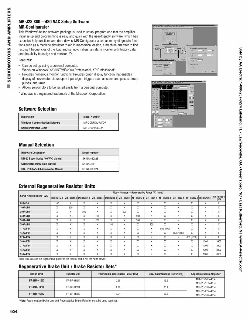
104
n
SE
RV
OM
OT
OR
S A
ND
AM
PL
IFIE
RS
MR-J2S 380 – 480 VAC Setup SoftwareMR-ConfiguratorThis Windows®-based software package is used to setup, program and test the amplifier.Initial setup and programming is easy and quick with the user-friendly software, which hasextensive help functions and drop-downs. MR-Configurator also has many diagnostic func-tions such as a machine simulator to aid in mechanical design, a machine analyzer to findresonant frequencies of the load and set notch filters, an alarm monitor with history data,and the ability to assign and monitor I/O.
Features:
• Can be set up using a personal computer.Works on Windows 95/98/NT/ME/2000 Professional, XP Professional*.
• Provides numerous monitor functions. Provides graph display function that enables display of servomotor status upon input signal triggers such as command pulses, drooppulses, and r/min.
• Allows servomotors to be tested easily from a personal computer.
* Windows is a registered trademark of the Microsoft Corporation.
Description Model Number
Windows Communication Software MR-CONFIGURATOR
Communications Cable MR-CPCATCBL3M
Software Selection
Hardware Description Model Number
MR-J2 Super Series 400 VAC Manual SH(NA)030026
Servomotor Instruction Manual SH(NA)3181
MR-HP30KA/55KA4 Converter Manual SH(NA)030024
Manual Selection
Note: This value is the regenerative power of the resistor and is not the rated power.
Servo-Amp Model (MR-J2S-)Model Number — Regenerative Power [W] (Note)
MR-RB1L-4 MR-RB3M-4 MR-RB3H-4 MR-RB3G-4 MR-RB34-4 MR-RB5H-4 MR-RB5G-4 MR-RB54-4 MR-RB6B-4 MR-RB60-4 MR-RB6K-4 MR-RB136-4 MR-RB138-4(x3)
60A4/B4 100 X X X X X X X X X X X X
100A4/B4 X 300 X X X X X X X X X X X
200A4/B4 X X 300 X X 500 X X X X X X X
350A4/B4 X X X 300 X X 500 X X X X X X
500A4/B4 X X X 300 X X 500 X X X X X X
700A4/B4 X X X X 300 X X 500 X X X X X
11KA4/B4 X X X X X X X X 500 (800) X X X X
15KA4/B4 X X X X X X X X X 850 (1300) X X X
22KA4/B4 X X X X X X X X X X 850 (1300) X X
30KA4/B4 X X X X X X X X X X X 1300 3900
37KA4/B4 X X X X X X X X X X X 1300 3900
45KA4/B4 X X X X X X X X X X X 1300 3900
55KA4/B4 X X X X X X X X X X X 1300 3900
External Regenerative Resistor Units
Regenerative Brake Unit / Brake Resistor Sets*
*Note: Regenerative Brake Unit and Regenerative Brake Resistor must be used together.
Brake Unit Resistor Unit Permissible Continuous Power (kw) Max. Instantaneous Power (kw) Applicable Servo Amplifier
FR-BU-H15K FR-BR-H15K 0.99 16.5 MR-J2S-500A4/B4MR-J2S-11KA4/B4MR-J2S-15KA4/B4MR-J2S-22KA4/B4MR-J2S-70KA4/B4
FR-BU-H30K FR-BR-H30K 1.99 33.4
FR-BU-H55K FR-BR-H55K 3.91 66.8
Sold by AA
Electric 1-800-237-8274 Lakeland, FL • Lawrenceville, G
A • G
reensboro, NC
• East Rutherford, N
J ww
w.A
-Aelectric.com
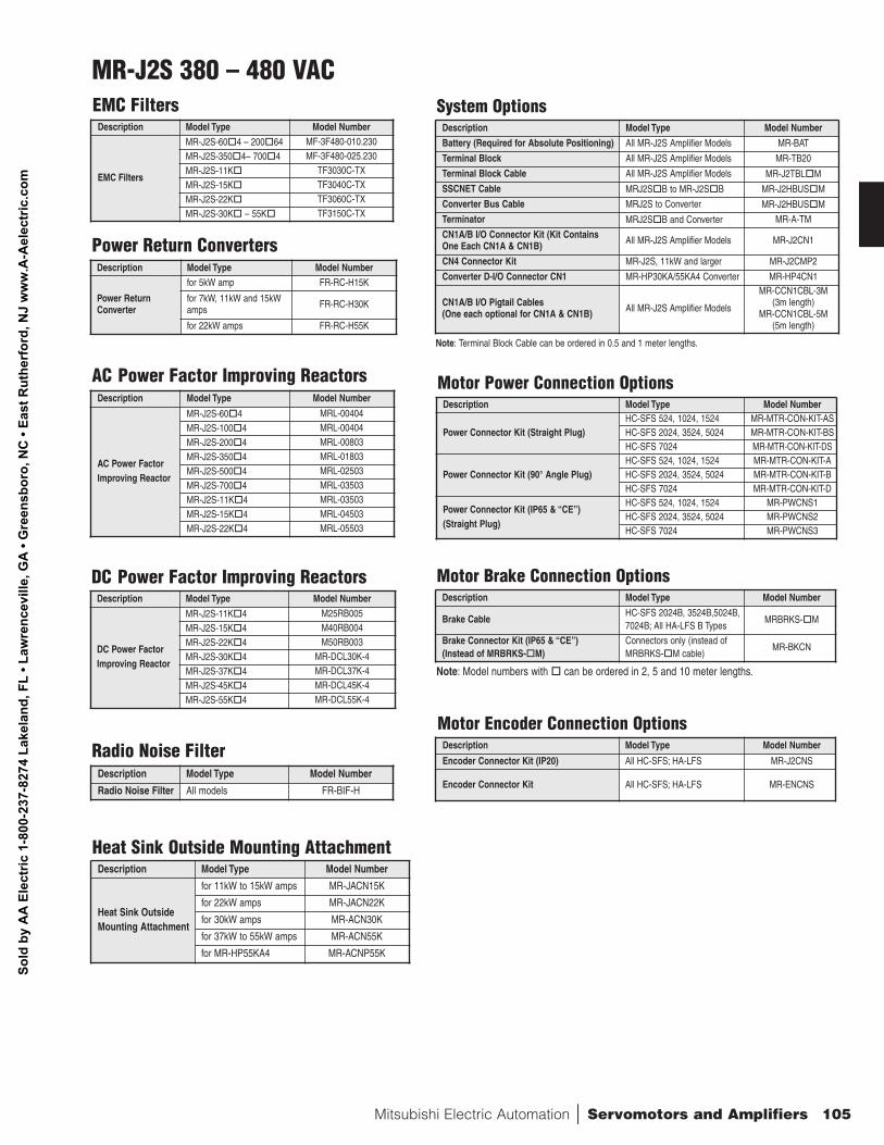
Mitsubishi Electric Automation | Servomotors and Amplifiers 105
Description Model Type Model Number
Heat Sink OutsideMounting Attachment
for 11kW to 15kW amps MR-JACN15K
for 22kW amps MR-JACN22K
for 30kW amps MR-ACN30K
for 37kW to 55kW amps MR-ACN55K
for MR-HP55KA4 MR-ACNP55K
Description Model Type Model Number
Radio Noise Filter All models FR-BIF-H
Radio Noise Filter
Heat Sink Outside Mounting Attachment
Note: Terminal Block Cable can be ordered in 0.5 and 1 meter lengths.
System Options
Motor Power Connection Options
Note: Model numbers with o
can be ordered in 2, 5 and 10 meter lengths.
Motor Brake Connection Options
Motor Encoder Connection Options
Power Return Converters
AC Power Factor Improving Reactors
Description Model Type Model Number
Power ReturnConverter
for 5kW amp FR-RC-H15K
for 7kW, 11kW and 15kWamps FR-RC-H30K
for 22kW amps FR-RC-H55K
Description Model Type Model Number
AC Power FactorImproving Reactor
MR-J2S-60o
4 MRL-00404
MR-J2S-100o
4 MRL-00404
MR-J2S-200o
4 MRL-00803
MR-J2S-350o
4 MRL-01803
MR-J2S-500o
4 MRL-02503
MR-J2S-700o
4 MRL-03503
MR-J2S-11Ko
4 MRL-03503
MR-J2S-15Ko
4 MRL-04503
MR-J2S-22Ko
4 MRL-05503
Description Model Type Model Number
DC Power FactorImproving Reactor
MR-J2S-11Ko
4 M25RB005
MR-J2S-15Ko
4 M40RB004
MR-J2S-22Ko
4 M50RB003
MR-J2S-30Ko
4 MR-DCL30K-4
MR-J2S-37Ko
4 MR-DCL37K-4
MR-J2S-45Ko
4 MR-DCL45K-4
MR-J2S-55Ko
4 MR-DCL55K-4
Description Model Type Model Number
EMC Filters
MR-J2S-60o
4 – 200o
64 MF-3F480-010.230
MR-J2S-350o
4– 700o
4 MF-3F480-025.230
MR-J2S-11Ko
TF3030C-TX
MR-J2S-15Ko
TF3040C-TX
MR-J2S-22Ko
TF3060C-TX
MR-J2S-30Ko
– 55Ko
TF3150C-TX
EMC Filters
DC Power Factor Improving Reactors
Description Model Type Model Number
Battery (Required for Absolute Positioning) All MR-J2S Amplifier Models MR-BAT
Terminal Block All MR-J2S Amplifier Models MR-TB20
Terminal Block Cable All MR-J2S Amplifier Models MR-J2TBLo
M
SSCNET Cable MRJ2So
B to MR-J2So
B MR-J2HBUSo
M
Converter Bus Cable MRJ2S to Converter MR-J2HBUSo
M
Terminator MRJ2So
B and Converter MR-A-TM
CN1A/B I/O Connector Kit (Kit Contains One Each CN1A & CN1B) All MR-J2S Amplifier Models MR-J2CN1
CN4 Connector Kit MR-J2S, 11kW and larger MR-J2CMP2
Converter D-I/O Connector CN1 MR-HP30KA/55KA4 Converter MR-HP4CN1
CN1A/B I/O Pigtail Cables (One each optional for CN1A & CN1B) All MR-J2S Amplifier Models
MR-CCN1CBL-3M(3m length)
MR-CCN1CBL-5M(5m length)
Description Model Type Model Number
Power Connector Kit (Straight Plug)HC-SFS 524, 1024, 1524 MR-MTR-CON-KIT-ASHC-SFS 2024, 3524, 5024 MR-MTR-CON-KIT-BSHC-SFS 7024 MR-MTR-CON-KIT-DS
Power Connector Kit (90° Angle Plug)HC-SFS 524, 1024, 1524 MR-MTR-CON-KIT-AHC-SFS 2024, 3524, 5024 MR-MTR-CON-KIT-BHC-SFS 7024 MR-MTR-CON-KIT-D
Power Connector Kit (IP65 & “CE”) (Straight Plug)
HC-SFS 524, 1024, 1524 MR-PWCNS1HC-SFS 2024, 3524, 5024 MR-PWCNS2HC-SFS 7024 MR-PWCNS3
Description Model Type Model Number
Brake CableHC-SFS 2024B, 3524B,5024B,7024B; All HA-LFS B Types
MRBRKS-o
M
Brake Connector Kit (IP65 & “CE”) (Instead of MRBRKS-o
M)Connectors only (instead ofMRBRKS-o
M cable)MR-BKCN
Description Model Type Model Number
Encoder Connector Kit (IP20) All HC-SFS; HA-LFS MR-J2CNS
Encoder Connector Kit All HC-SFS; HA-LFS MR-ENCNS
MR-J2S 380 – 480 VAC
Sold
by
AA
Ele
ctric
1-8
00-2
37-8
274
Lake
land
, FL
• Law
renc
evill
e, G
A •
Gre
ensb
oro,
NC
• Ea
st R
uthe
rfor
d, N
J w
ww
.A-A
elec
tric
.com
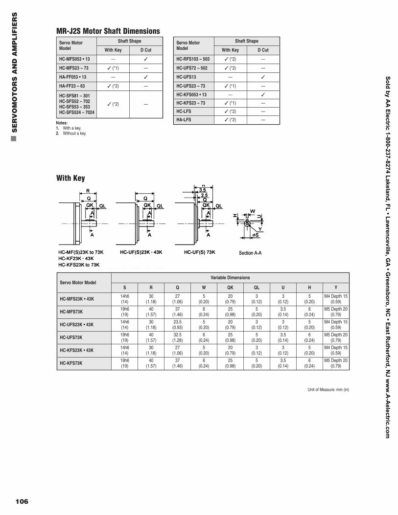
106
n
SE
RV
OM
OT
OR
S A
ND
AM
PL
IFIE
RS
Servo MotorModel
Shaft Shape
With Key D Cut
HC-MFS053 • 13 — 3
HC-MFS23 – 73 3 (*1) —
HA-FF053 • 13 — 3
HA-FF23 – 63 3 (*2) —
HC-SFS81 – 301HC-SFS52 – 702HC-SFS53 – 353HC-SFS524 – 7024
3 (*2) —
Servo MotorModel
Shaft Shape
With Key D Cut
HC-RFS103 – 503 3 (*2) —
HC-UFS72 – 502 3 (*2) —
HC-UFS13 — 3
HC-UFS23 – 73 3 (*1) —
HC-KFS053 • 13 — 3
HC-KFS23 – 73 3 (*1) —
HC-LFS 3 (*2) —
HA-LFS 3 (*2) —
MR-J2S Motor Shaft Dimensions
With Key
Notes:1. With a key.2. Without a key.
Servo Motor ModelVariable Dimensions
S R Q W QK QL U H Y
HC-MFS23K • 43K 14h6 (14)
30(1.18)
27(1.06)
5(0.20)
20(0.79)
3(0.12)
3(0.12)
5(0.20)
M4 Depth 15(0.59)
HC-MFS73K 19h6(19)
40(1.57)
37(1.46)
6(0.24)
25(0.98)
5(0.20)
3.5(0.14)
6(0.24)
M5 Depth 20(0.79)
HC-UFS23K • 43K 14h6 (14)
30(1.18)
23.5(0.93)
5(0.20)
20(0.79)
3(0.12)
3(0.12)
5(0.20)
M4 Depth 15(0.59)
HC-UFS73K 19h6(19)
40(1.57)
32.5(1.28)
6(0.24)
25(0.98)
5(0.20)
3.5(0.14)
6(0.24)
M5 Depth 20(0.79)
HC-KFS23K • 43K 14h6 (14)
30(1.18)
27(1.06)
5(0.20)
20(0.79)
3(0.12)
3(0.12)
5(0.20)
M4 Depth 15(0.59)
HC-KFS73K 19h6(19)
40(1.57)
37(1.46)
6(0.24)
25(0.98)
5(0.20)
3.5(0.14)
6(0.24)
M5 Depth 20(0.79)
Unit of Measure: mm (in)
Sold by AA
Electric 1-800-237-8274 Lakeland, FL • Lawrenceville, G
A • G
reensboro, NC
• East Rutherford, N
J ww
w.A
-Aelectric.com
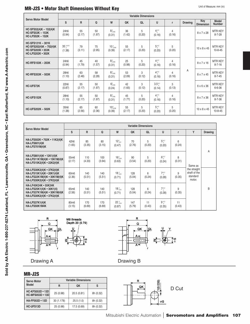
Mitsubishi Electric Automation | Servomotors and Amplifiers 107
Servo Motor ModelVariable Dimensions
S R Q W QK QL U r Y Drawing
HA-LFS502K • 702K • 11K2(4)KHA-LFS601(4)KHA-LFS701M(4)K
42h6 (1.65)
85(3.35)
80(3.15)
12 00.01
(0.47)70
(2.76)5
(0.20)5+0.2
0
(0.20)6
(0.24)
Same as the straightshaft of the
standardmotor.
A
HA-LFS801(4)K • 12K1(4)KHA-LFS11K1M(4)K • 15K1M(4)KHA-LFS15K2(4)K • 22K2(4)K
55m6(2.17)
110(4.33)
100(3.94)
16 0-0.04
(0.63)90
(3.54)5
(0.20)6+0.2
0
(0.24)8
(0.31)
HA-LFS30K2(4)K • 37K2(4)KHA-LFS15K1(4)K • 20K1(4)KHA-LFS22K1M(4)K • 30K1M(4)KHA-LFS30K2(4)K • 37K2(4)K
60m6(2.36)
140(5.51)
140(5.51)
18 0-0.03
(0.71)128
(5.04)6
(0.24)7+0.2
0
(0.28)9
(0.35)
BHA-LF45K24K • 55K24KHA-LFS25K1(4)K • 30K1(4)HA-LFS37K1M(4)K • 30K1M(4)KHA-LFS30K2(4)K • 37K2(4)K
65m6(2.56)
140(5.51)
140(5.51)
18 0-0.03
(0.71)128
(5.04)6
(0.24)7+0.2
0
(0.28)9
(0.35)
HA-LFS37K1(4)KHA-LFS50K1M4K
80m6 (3.15)
170(6.69)
170(6.69)
22 0-0.04
(0.87)147
(5.79)11
(0.43)9 +0.2
0
(0.35)11
(0.43)
MR-J2S • Motor Shaft Dimensions Without Key
Drawing A Drawing B
Servo Motor ModelVariable Dimensions
S R Q W QK QL U r Drawing KeyDimension
ModelNumber
HC-SFS52(4)K – 152(4)KHC-SFS53K – 153KHC-LFS52K – 152K
24h6 (0.94)
55(2.17)
50(1.97)
8 0-0.036
(0.31)36
(1.42)5
(0.20)4+0.2
0
(0.16)4
(0.16)
A
8 x 7 x 28 MTR KEY8-7-28
HC-SFS121K – 301KHC-SFS202(4)K – 702(4)KHC-SFS203K • 353KHC-LFS202K • 302K
35 +0.0100
(1.38)79
(3.11)75
(2.95)10 0
-0.036
(0.39)55
(2.17)5
(0.20)5+0.2
0
(0.20)5
(0.20) 10 x 8 x 45 MTR KEY10-8-45
HC-RFS103K – 203K 24h6 (0.94)
45(1.79)
40(1.57)
8 0-0.036
(0.31)25
(0.98)5
(0.20)4+0.2
0
(0.16)4
(0.16) 8 x 7 x 16 MTR KEY8-7-16
HC-RFS353K – 503K 28h6 (1.10)
63(2.48)
58(2.28)
8 0-0.036
(0.31)53
(2.09)3
(0.12)4+0.2
0
(0.16)4
(0.16) 8 x 7 x 45 MTR KEY8-7-45
HC-UFS72K 22h6 (0.87)
55(2.17)
50(1.97)
60-0.036
(0.24)42
(1.65)3
(0.12)3.5+0.1
0
(0.14)3
(0.13) 6 x 6 x 36 MTR KEY6-6-36
HC-UFS152K 28h6 (1.10)
55(2.17)
50(1.97)
8 0-0.036
(0.31)45
(1.77)5
(0.20)4+0.2
0
(0.16)4
(0.16) 8 x 7 x 36 MTR KEY8-7-36
HC-UFS202K – 502K 35h6 (1.38)
65(2.56)
60(2.36)
10 0-0.036
(0.39)55
(2.17)5
(0.20)5+0.2
0
(0.20)5
(0.20) 10 x 8 x 45 MTR KEY10-8-45
Unit of Measure: mm (in)
MR-J2SServo MotorModel
Variable Dimensions
R QK S
HC-KFS053D • 13DHC-MFS053D • 13D 25 (0.98) 20.5 (0.81) 8h (0.32)
HA-FF053D • 13D 30 (1.178) 25.5 (1.0) 8h (0.32)
HC-UFS13D 25 (0.98) 17.5 (0.69) 8h (0.32)
D Cut
Sold
by
AA
Ele
ctric
1-8
00-2
37-8
274
Lake
land
, FL
• Law
renc
evill
e, G
A •
Gre
ensb
oro,
NC
• Ea
st R
uthe
rfor
d, N
J w
ww
.A-A
elec
tric
.com
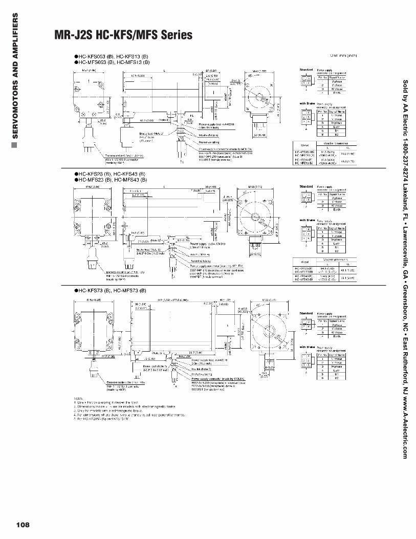
108
n
SE
RV
OM
OT
OR
S A
ND
AM
PL
IFIE
RS
MR-J2S HC-KFS/MFS Series
Sold by AA
Electric 1-800-237-8274 Lakeland, FL • Lawrenceville, G
A • G
reensboro, NC
• East Rutherford, N
J ww
w.A
-Aelectric.com
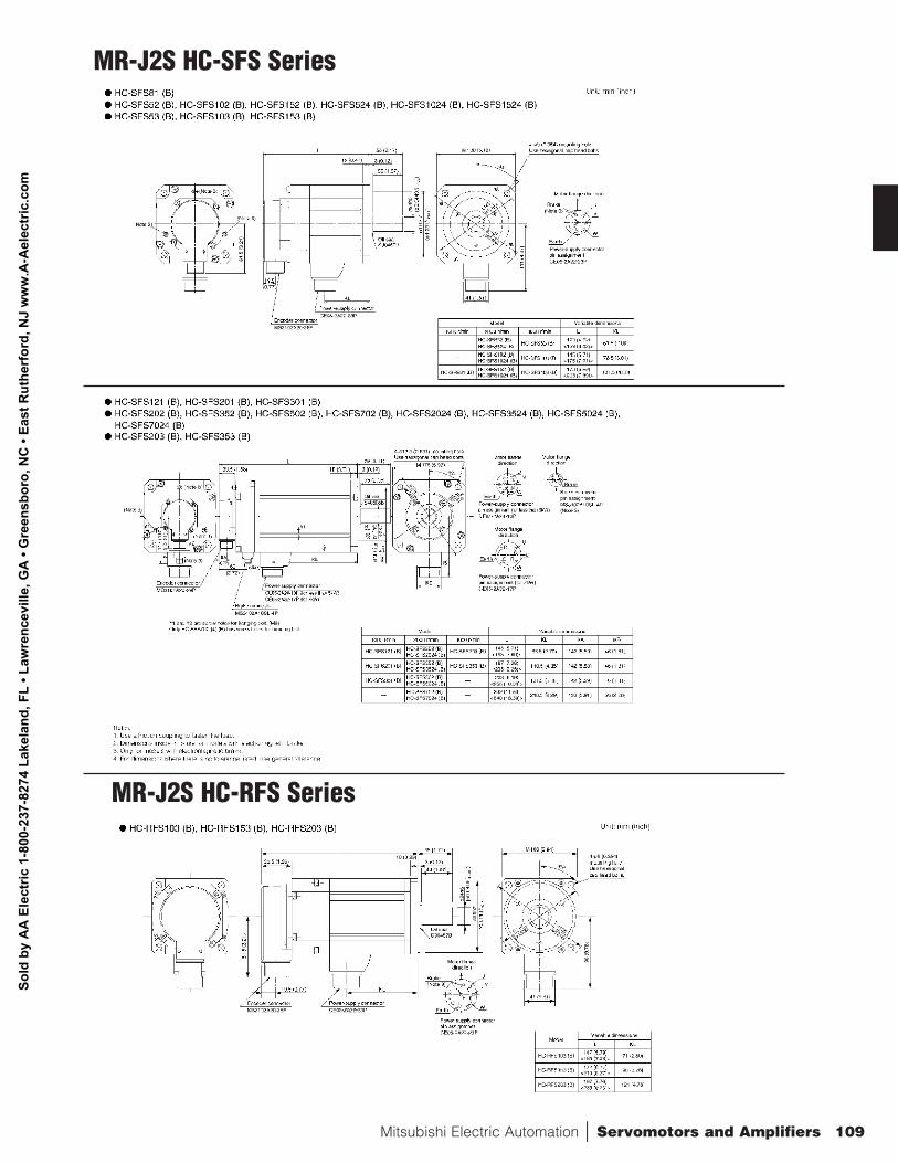
Mitsubishi Electric Automation | Servomotors and Amplifiers 109
MR-J2S HC-SFS Series
MR-J2S HC-RFS Series
Sold
by
AA
Ele
ctric
1-8
00-2
37-8
274
Lake
land
, FL
• Law
renc
evill
e, G
A •
Gre
ensb
oro,
NC
• Ea
st R
uthe
rfor
d, N
J w
ww
.A-A
elec
tric
.com
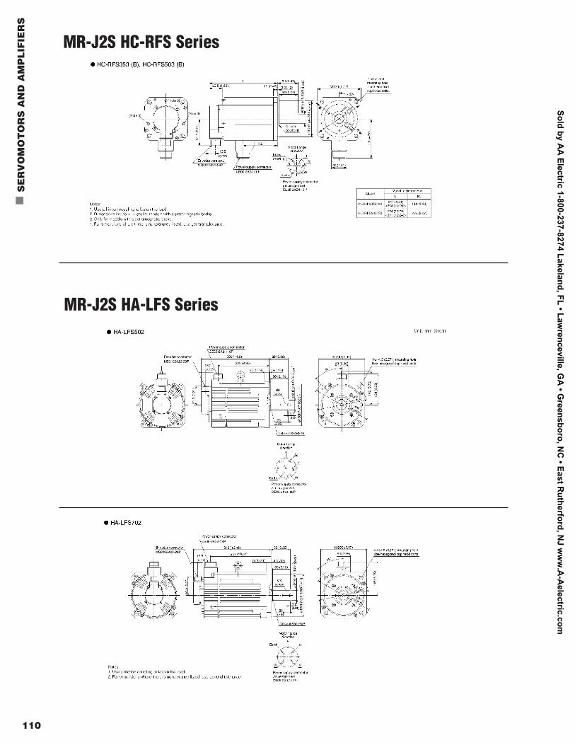
110
n
SE
RV
OM
OT
OR
S A
ND
AM
PL
IFIE
RS
MR-J2S HA-LFS Series
MR-J2S HC-RFS Series
Sold by AA
Electric 1-800-237-8274 Lakeland, FL • Lawrenceville, G
A • G
reensboro, NC
• East Rutherford, N
J ww
w.A
-Aelectric.com
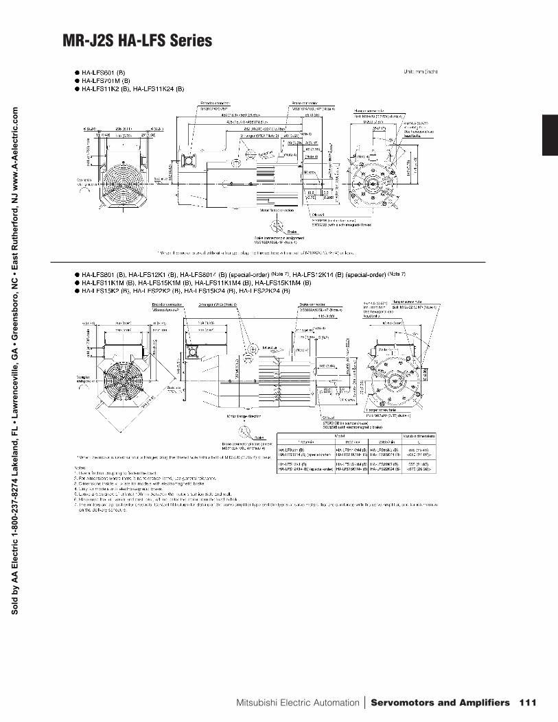
Mitsubishi Electric Automation | Servomotors and Amplifiers 111
MR-J2S HA-LFS Series
Sold
by
AA
Ele
ctric
1-8
00-2
37-8
274
Lake
land
, FL
• Law
renc
evill
e, G
A •
Gre
ensb
oro,
NC
• Ea
st R
uthe
rfor
d, N
J w
ww
.A-A
elec
tric
.com
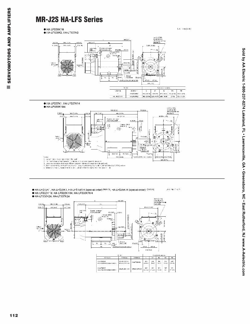
112
n
SE
RV
OM
OT
OR
S A
ND
AM
PL
IFIE
RS
MR-J2S HA-LFS Series
Sold by AA
Electric 1-800-237-8274 Lakeland, FL • Lawrenceville, G
A • G
reensboro, NC
• East Rutherford, N
J ww
w.A
-Aelectric.com
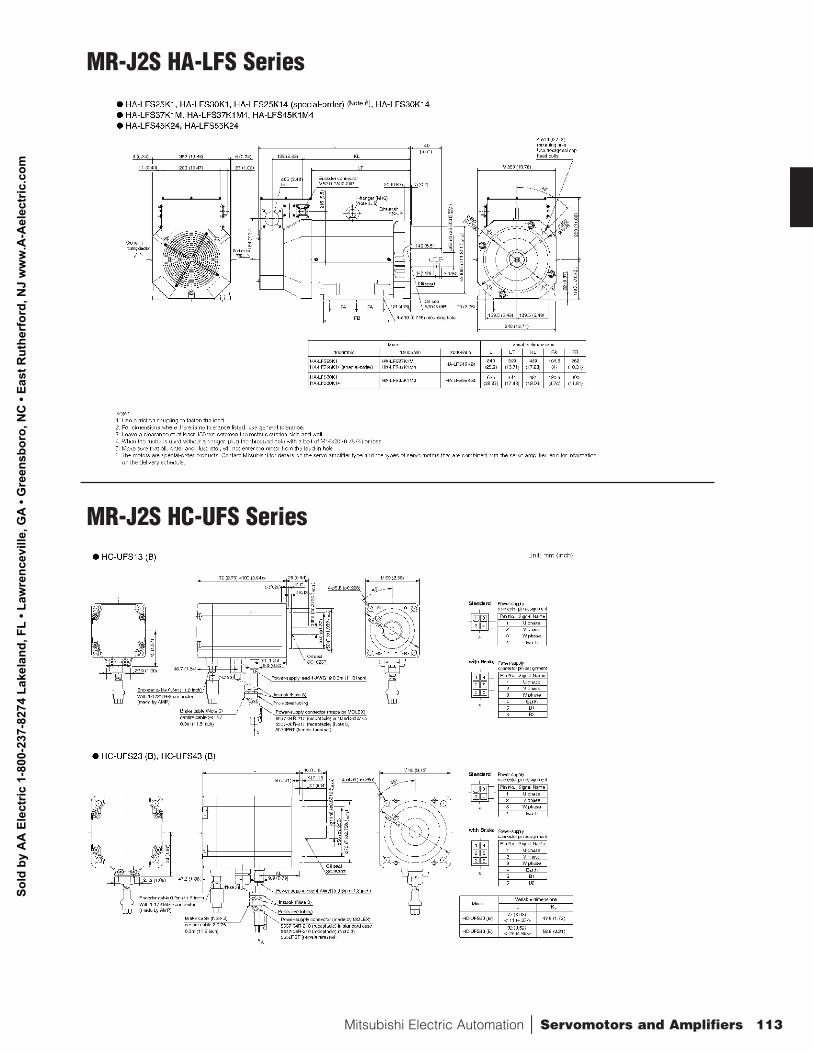
Mitsubishi Electric Automation | Servomotors and Amplifiers 113
MR-J2S HC-UFS Series
MR-J2S HA-LFS Series
Sold
by
AA
Ele
ctric
1-8
00-2
37-8
274
Lake
land
, FL
• Law
renc
evill
e, G
A •
Gre
ensb
oro,
NC
• Ea
st R
uthe
rfor
d, N
J w
ww
.A-A
elec
tric
.com
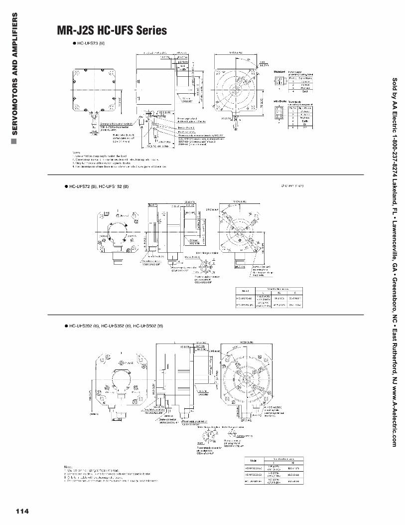
114
n
SE
RV
OM
OT
OR
S A
ND
AM
PL
IFIE
RS
MR-J2S HC-UFS Series
Sold by AA
Electric 1-800-237-8274 Lakeland, FL • Lawrenceville, G
A • G
reensboro, NC
• East Rutherford, N
J ww
w.A
-Aelectric.com
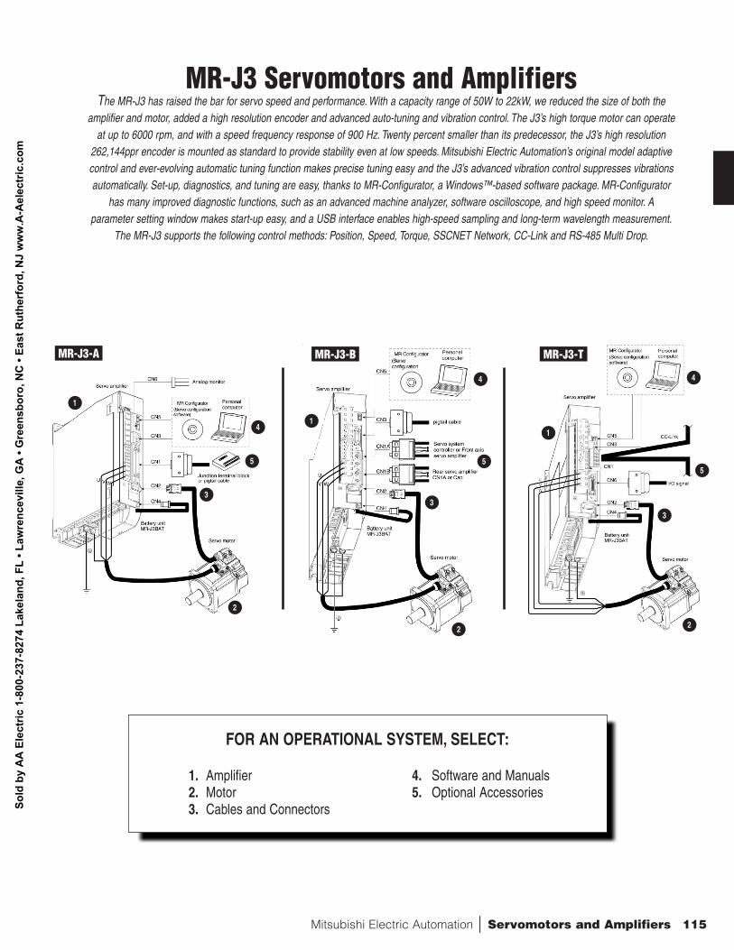
Mitsubishi Electric Automation | Servomotors and Amplifiers 115
FOR AN OPERATIONAL SYSTEM, SELECT:
1. Amplifier 4. Software and Manuals2. Motor 5. Optional Accessories3. Cables and Connectors
MR-J3 Servomotors and AmplifiersThe MR-J3 has raised the bar for servo speed and performance. With a capacity range of 50W to 22kW, we reduced the size of both the
amplifier and motor, added a high resolution encoder and advanced auto-tuning and vibration control. The J3’s high torque motor can operateat up to 6000 rpm, and with a speed frequency response of 900 Hz. Twenty percent smaller than its predecessor, the J3’s high resolution
262,144ppr encoder is mounted as standard to provide stability even at low speeds. Mitsubishi Electric Automation’s original model adaptivecontrol and ever-evolving automatic tuning function makes precise tuning easy and the J3’s advanced vibration control suppresses vibrationsautomatically. Set-up, diagnostics, and tuning are easy, thanks to MR-Configurator, a Windows™-based software package. MR-Configurator
has many improved diagnostic functions, such as an advanced machine analyzer, software oscilloscope, and high speed monitor. A parameter setting window makes start-up easy, and a USB interface enables high-speed sampling and long-term wavelength measurement.
The MR-J3 supports the following control methods: Position, Speed, Torque, SSCNET Network, CC-Link and RS-485 Multi Drop.
MR-J3-A MR-J3-B MR-J3-T
1
4
4
1
4
5
3
2
5
3
2
1
5
3
2
Sold
by
AA
Ele
ctric
1-8
00-2
37-8
274
Lake
land
, FL
• Law
renc
evill
e, G
A •
Gre
ensb
oro,
NC
• Ea
st R
uthe
rfor
d, N
J w
ww
.A-A
elec
tric
.com
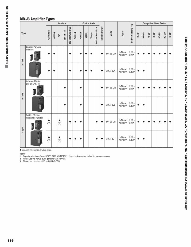
116
n
SE
RV
OM
OT
OR
S A
ND
AM
PL
IFIE
RS
Type
Interface Control Mode
Setu
p So
ftwar
e
Mod
el
Pow
er
Sour
ce C
apac
ity (*
1)
Compatible Motor Series
Puls
e Tr
ain
Anal
og
DIO
SSCN
ET II
I
RS-4
22 M
ulti-
Drop
CC-L
ink
Posi
tion
Spee
d
Torq
ue
Posi
tion
Func
tions
HF-K
P
HF-M
P
HF-S
P
HC-L
P
HC-R
P
HC-U
P
HA-L
P
A-Ty
pe
l l l l l l l
MR-J3-o
A3-PhaseAC 200V
0.05 ~22kW l l l l l l l
l l l l l l l
MR-J3-o
A11-PhaseAC 100V
0.05 ~0.4kW l l
B-Ty
pe
l l l
MR-J3-o
B3-PhaseAC 200V
0.05 ~22kW l l l l l l l
l l l
MR-J3-o
B11-PhaseAC 100V
0.05 ~0.4kW l l
T-Ty
pe
l
(*2)l
(*3)l l l l l
MR-J3-o
T3-PhaseAC 200V
0.05 ~22kW l l l l l l l
l
(*2)l
(*3)l l l l l
MR-J3-o
T11-PhaseAC 100V
0.05 ~0.4kW l l
General PurposeInterface
Advanced SerialBus SSCNET III
Built-In CC-LinkPositioning Function
l
indicates the available product range.
Notes:1. Capacity selection software MSIZE (MRZJW3-MOTSZ111) can be downloaded for free from www.meau.com.2. Please use the manual pulse generator (MR-HDP01).3. Please use the extended IO unit (MR-J3-D01).
MR-J3 Amplifier Types
Sold by AA
Electric 1-800-237-8274 Lakeland, FL • Lawrenceville, G
A • G
reensboro, NC
• East Rutherford, N
J ww
w.A
-Aelectric.com
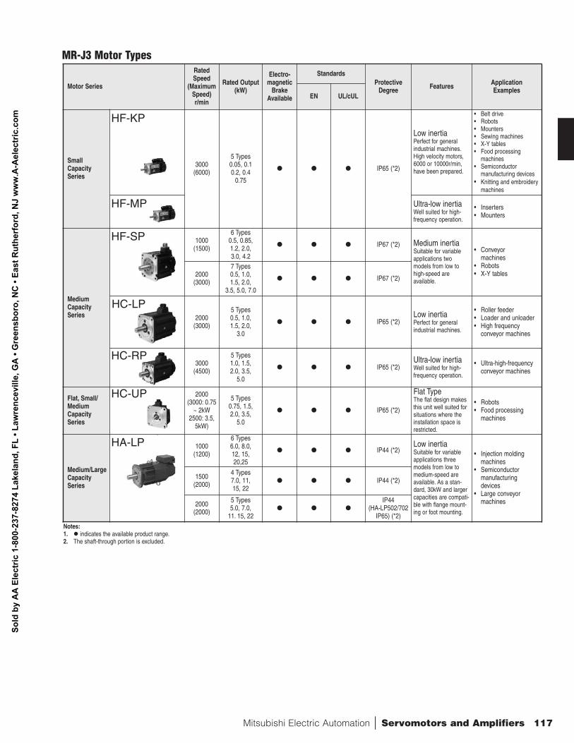
Mitsubishi Electric Automation | Servomotors and Amplifiers 117
Notes:1. l
indicates the available product range.2. The shaft-through portion is excluded.
Motor Series
RatedSpeed
(MaximumSpeed)r/min
Rated Output (kW)
Electro-magnetic
BrakeAvailable
StandardsProtective
Degree Features Application Examples
EN UL/cUL
Small CapacitySeries
3000(6000)
5 Types0.05, 0.10.2, 0.4
0.75
l l l
IP65 (*2)
Low inertiaPerfect for generalindustrial machines.High velocity motors,6000 or 10000r/min,have been prepared.
• Belt drive • Robots • Mounters • Sewing machines • X-Y tables • Food processing
machines • Semiconductor
manufacturing devices• Knitting and embroidery
machines
Ultra-low inertiaWell suited for high-frequency operation.
• Inserters • Mounters
MediumCapacitySeries
1000(1500)
6 Types0.5, 0.85,1.2, 2.0,3.0, 4.2
l l l
IP67 (*2) Medium inertiaSuitable for variableapplications twomodels from low tohigh-speed are available.
• Conveyormachines
• Robots• X-Y tables2000
(3000)
7 Types0.5, 1.0,1.5, 2.0,
3.5, 5.0, 7.0
l l l
IP67 (*2)
2000(3000)
5 Types0.5, 1.0, 1.5, 2.0,
3.0
l l l
IP65 (*2)Low inertiaPerfect for generalindustrial machines.
• Roller feeder• Loader and unloader• High frequency
conveyor machines
3000(4500)
5 Types1.0, 1.5,2.0, 3.5,
5.0
l l l
IP65 (*2)Ultra-low inertiaWell suited for high-frequency operation.
• Ultra-high-frequencyconveyor machines
Flat, Small/MediumCapacitySeries
2000(3000: 0.75
~ 2kW2500: 3.5,
5kW)
5 Types0.75, 1.5,2.0, 3.5,
5.0
l l l
IP65 (*2)
Flat TypeThe flat design makesthis unit well suited forsituations where theinstallation space isrestricted.
• Robots • Food processing
machines
Medium/LargeCapacitySeries
1000(1200)
6 Types6.0, 8.0,12, 15,20,25
l l l
IP44 (*2)Low inertiaSuitable for variableapplications three models from low tomedium-speed areavailable. As a stan-dard, 30kW and largercapacities are compati-ble with flange mount-ing or foot mounting.
• Injection moldingmachines
• Semiconductormanufacturingdevices
• Large conveyormachines
1500(2000)
4 Types7.0, 11,15, 22
l l l
IP44 (*2)
2000(2000)
5 Types5.0, 7.0,
11. 15, 22l l l
IP44 (HA-LP502/702
IP65) (*2)
HF-KP
HF-MP
HF-SP
HC-LP
HC-RP
HC-UP
HA-LP
MR-J3 Motor Types
Sold
by
AA
Ele
ctric
1-8
00-2
37-8
274
Lake
land
, FL
• Law
renc
evill
e, G
A •
Gre
ensb
oro,
NC
• Ea
st R
uthe
rfor
d, N
J w
ww
.A-A
elec
tric
.com
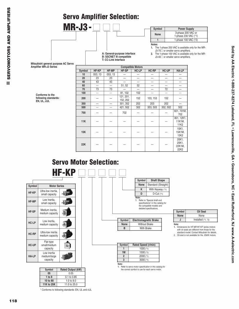
118
n
SE
RV
OM
OT
OR
S A
ND
AM
PL
IFIE
RS
Compatible MotorsSymbol HF-KP HF-MP HF-SP HC-LP HC-RP HC-UP HA-LP
10 053, 13 053, 13 — — — — —20 23 23 — — — — —40 43 43 — — — — —60 — — 51, 52 52 — — —70 73 73 — — — 72 —100 — — 81, 102 102 — — —
200 — — 121, 201,152, 202 152 103, 153 152 —
350 — — 301, 352 202 203 202 —500 — — 421, 502 302 353, 503 352, 502 502
700 — — 702 — — — 601, 701M,702
11K — — — — — —801, 12K1,
11K1M,11K2
15K — — — — — —15K1,
15K1M,15K2
22K — — — — — —
20K1,25K1,
22K1M,22K2
Servo Amplifier Selection:
MR-J3- nn nn nn
Mitsubishi general purpose AC ServoAmplifier MR-J3 Series
A: General-purpose interfaceB: SSCNET III compatibleT: CC-Link Interface
Conforms to the following standards:EN, UL, cUL
Symbol Power Supply
None 3-phase 200 VAC or 1-phase 230 VAC (*1)
1 1-phase 100 VAC (*2)
Notes:1. The 1-phase 200 VAC is available only for the MR-
J3-70nn or smaller servo amplifiers.2. The 1-phase 100 VAC is available only for the MR-
J3-40nn or smaller servo amplifiers.
Servo Motor Selection:
HF-KP nn nn nn nn nn
Symbol Rated Speed (r/min)1 1000 (*1)
1M 1500 (*1)
2 2000 (*1)
3 3000 (*1)
Symbol Rated Output (kW)05 0.05
1 to 8 0.1 to 0.8510 to 80 1.0 to 8.0
11K to 25K 11.0 to 25.0
Note:1. Refer to “Special shaft end
specifications” in this catalog forthe compatible models anddetailed specifications.
Note:1. Dimensions for HF-MP/HF-KP series motors
with oil seals are different from those for thestandard model. Contact Mitsubishi for details.
2. Oil-seal is not available for the .05kW motors.
Symbol Shaft Shape
None Standard (Straight)
K With Keyway (*1)
D D-Cut (*1)
Symbol Electromagnetic BrakeNone Without Brake
B With Brake
Symbol Oil SealNone None
J Installed (*1, *2)
Symbol Motor Series
HF-KP Ultra-low inertia,small capacity
HF-MP Low inertia,small capacity
HF-SP Medium inertia,medium capacity
HC-LP Low inertia, medium capacity
HC-RP Ultra-low inertiamedium capacity
HC-UPFlat type
small/mediumcapacity
HA-LPLow inertia
medium/largecapacity
* Conforms to following standards: EN, UL and cUL
Note:1. Refer to servo motor specification in this catalog for
the correct symbol to use for each servo motor.
Sold by AA
Electric 1-800-237-8274 Lakeland, FL • Lawrenceville, G
A • G
reensboro, NC
• East Rutherford, N
J ww
w.A
-Aelectric.com
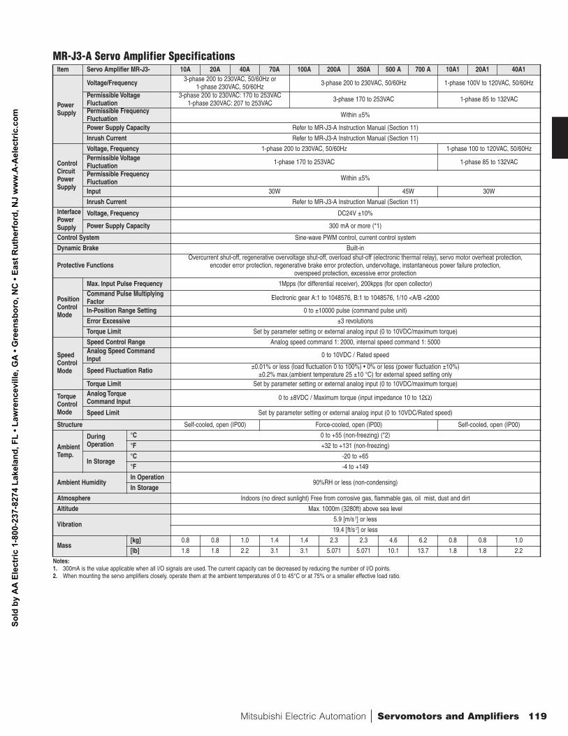
Mitsubishi Electric Automation | Servomotors and Amplifiers 119
Item Servo Amplifier MR-J3- 10A 20A 40A 70A 100A 200A 350A 500 A 700 A 10A1 20A1 40A1
Power Supply
Voltage/Frequency 3-phase 200 to 230VAC, 50/60Hz or 1-phase 230VAC, 50/60Hz 3-phase 200 to 230VAC, 50/60Hz 1-phase 100V to 120VAC, 50/60Hz
Permissible Voltage Fluctuation
3-phase 200 to 230VAC: 170 to 253VAC 1-phase 230VAC: 207 to 253VAC 3-phase 170 to 253VAC 1-phase 85 to 132VAC
Permissible FrequencyFluctuation Within ±5%
Power Supply Capacity Refer to MR-J3-A Instruction Manual (Section 11)
Inrush Current Refer to MR-J3-A Instruction Manual (Section 11)
ControlCircuitPowerSupply
Voltage, Frequency 1-phase 200 to 230VAC, 50/60Hz 1-phase 100 to 120VAC, 50/60Hz Permissible VoltageFluctuation 1-phase 170 to 253VAC 1-phase 85 to 132VAC
Permissible FrequencyFluctuation Within ±5%
Input 30W 45W 30W
Inrush Current Refer to MR-J3-A Instruction Manual (Section 11)InterfacePowerSupply
Voltage, Frequency DC24V ±10%
Power Supply Capacity 300 mA or more (*1)
Control System Sine-wave PWM control, current control system
Dynamic Brake Built-in
Protective FunctionsOvercurrent shut-off, regenerative overvoltage shut-off, overload shut-off (electronic thermal relay), servo motor overheat protection,
encoder error protection, regenerative brake error protection, undervoltage, instantaneous power failure protection, overspeed protection, excessive error protection
PositionControlMode
Max. Input Pulse Frequency 1Mpps (for differential receiver), 200kpps (for open collector)Command Pulse MultiplyingFactor Electronic gear A:1 to 1048576, B:1 to 1048576, 1/10 <A/B <2000
In-Position Range Setting 0 to ±10000 pulse (command pulse unit)
Error Excessive ±3 revolutions
Torque Limit Set by parameter setting or external analog input (0 to 10VDC/maximum torque)
SpeedControlMode
Speed Control Range Analog speed command 1: 2000, internal speed command 1: 5000Analog Speed CommandInput 0 to 10VDC / Rated speed
Speed Fluctuation Ratio ±0.01% or less (load fluctuation 0 to 100%) • 0% or less (power fluctuation ±10%)±0.2% max.(ambient temperature 25 ±10 °C) for external speed setting only
Torque Limit Set by parameter setting or external analog input (0 to 10VDC/maximum torque)
TorqueControlMode
Analog Torque Command Input 0 to ±8VDC / Maximum torque (input impedance 10 to 12Ω)
Speed Limit Set by parameter setting or external analog input (0 to 10VDC/Rated speed)
Structure Self-cooled, open (IP00) Force-cooled, open (IP00) Self-cooled, open (IP00)
AmbientTemp.
DuringOperation
°C 0 to +55 (non-freezing) (*2)
°F +32 to +131 (non-freezing)
In Storage°C -20 to +65
°F -4 to +149
Ambient HumidityIn Operation
90%RH or less (non-condensing)In Storage
Atmosphere Indoors (no direct sunlight) Free from corrosive gas, flammable gas, oil mist, dust and dirt
Altitude Max. 1000m (3280ft) above sea level
Vibration 5.9 [m/s 2] or less
19.4 [ft/s 2] or less
Mass [kg] 0.8 0.8 1.0 1.4 1.4 2.3 2.3 4.6 6.2 0.8 0.8 1.0
[lb] 1.8 1.8 2.2 3.1 3.1 5.071 5.071 10.1 13.7 1.8 1.8 2.2
MR-J3-A Servo Amplifier Specifications
Notes:1. 300mA is the value applicable when all I/O signals are used. The current capacity can be decreased by reducing the number of I/O points.2. When mounting the servo amplifiers closely, operate them at the ambient temperatures of 0 to 45°C or at 75% or a smaller effective load ratio.
Sold
by
AA
Ele
ctric
1-8
00-2
37-8
274
Lake
land
, FL
• Law
renc
evill
e, G
A •
Gre
ensb
oro,
NC
• Ea
st R
uthe
rfor
d, N
J w
ww
.A-A
elec
tric
.com
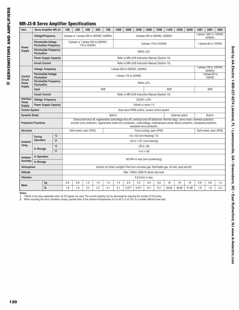
120
n
SE
RV
OM
OT
OR
S A
ND
AM
PL
IFIE
RS
MR-J3-B Servo Amplifier SpecificationsItem Servo Amplifier MR-J3- 10B 20B 40B 60B 70B 100B 200B 350B 500B 700B 11KB 15KB 22KB 10B1 20B1 40B1
PowerSupply
Voltage/Frequency 3-phase or 1-phase 200 to 230VAC, 50/60Hz 3-phase 200 to 230VAC, 50/60Hz 1-phase 100V to 120VAC,50/60Hz
Permissible Voltage Fluctuation Frequency
3-phase or 1-phase 200 to 230VAC:170 to 253VAC 3-phase 170 to 253VAC 1-phase 85 to 132VAC
Permissible FrequencyFluctuation Within ±5%
Power Supply Capacity Refer to MR-J3-B Instruction Manual (Section 10)
Inrush Current Refer to MR-J3-B Instruction Manual (Section 10)
ControlCircuitPowerSupply
Voltage, Frequency 1-phase 200 to 230VAC, 50/60Hz 1-phase 100 to 120VAC,50/60Hz
Permissible Voltage Fluctuation 1-phase 170 to 253VAC 1-phase 85 to
132VACPermissible FrequencyFluctuation Within ±5%
Input 30W 45W 30W
Inrush Current Refer to MR-J3-B Instruction Manual (Section 10)
InterfacePowerSupply
Voltage, Frequency DC24V ±10%
Power Supply Capacity 150mA or more (*1)
Control System Sine-wave PWM control, current control system
Dynamic Brake Built-in External option Built-in
Protective FunctionsOvercurrent shut-off, regenerative overvoltage shut-off, overload shut-off (electronic thermal relay), servo motor overheat protection,
encoder error protection, regenerative brake error protection, undervoltage, instantaneous power failure protection, overspeed protection, excessive error protection
Structure Self-cooled, open (IP00) Force-cooling, open (IP00) Self-cooled, open (IP00)
AmbientTemp.
DuringOperation
°C 0 to +55 (non-freezing) (*2)
°F +32 to +131 (non-freezing)
In Storage°C -20 to +65
°F -4 to +149
AmbientHumidity
In Operation90%RH or less (non-condensing)
In Storage
Atmosphere Indoors (no direct sunlight) Free from corrosive gas, flammable gas, oil mist, dust and dirt
Altitude Max. 1000m (3280 ft) above sea level
Vibration 5.9 [m/s2] or less
Masskg 0.8 0.8 1.0 1.0 1.4 1.4 2.3 2.3 4.6 6.2 18 18 19 0.8 0.8 1.0
lb 1.8 1.8 2.2 2.2 3.1 3.1 5.071 5.071 10.1 13.7 39.68 39.68 41.88 1.8 1.8 2.2
Notes:1. 150mA is the value applicable when all I/O signals are used. The current capacity can be decreased by reducing the number of I/O points.2. When mounting the servo amplifiers closely, operate them at the ambient temperatures of 0 to 45°C or at 75% or a smaller effective load ratio.
Sold by AA
Electric 1-800-237-8274 Lakeland, FL • Lawrenceville, G
A • G
reensboro, NC
• East Rutherford, N
J ww
w.A
-Aelectric.com
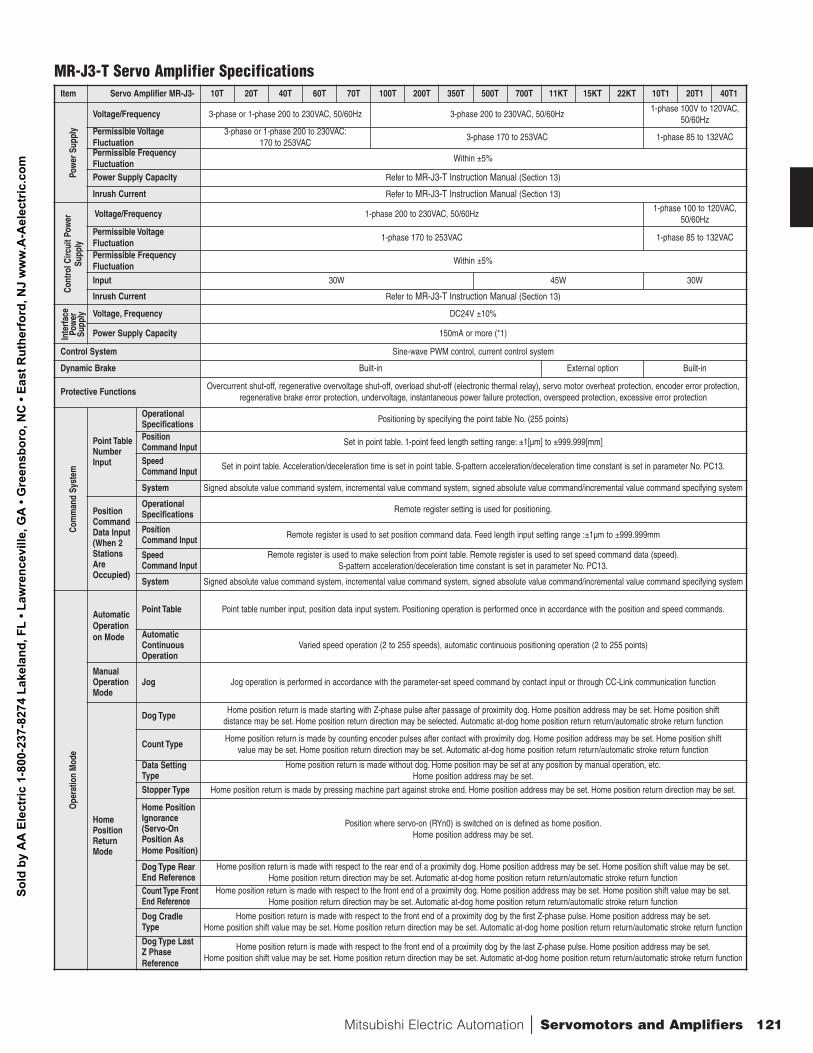
Mitsubishi Electric Automation | Servomotors and Amplifiers 121
Item Servo Amplifier MR-J3- 10T 20T 40T 60T 70T 100T 200T 350T 500T 700T 11KT 15KT 22KT 10T1 20T1 40T1
Pow
er S
uppl
y
Voltage/Frequency 3-phase or 1-phase 200 to 230VAC, 50/60Hz 3-phase 200 to 230VAC, 50/60Hz 1-phase 100V to 120VAC,
50/60Hz Permissible VoltageFluctuation
3-phase or 1-phase 200 to 230VAC:170 to 253VAC
3-phase 170 to 253VAC 1-phase 85 to 132VAC
Permissible Frequency Fluctuation
Within ±5%
Power Supply Capacity Refer to MR-J3-T Instruction Manual (Section 13)
Inrush Current Refer to MR-J3-T Instruction Manual (Section 13)
Cont
rol C
ircui
t Pow
er
Supp
ly
Voltage/Frequency 1-phase 200 to 230VAC, 50/60Hz 1-phase 100 to 120VAC,
50/60Hz Permissible Voltage Fluctuation
1-phase 170 to 253VAC 1-phase 85 to 132VAC
Permissible Frequency Fluctuation
Within ±5%
Input 30W 45W 30W
Inrush Current Refer to MR-J3-T Instruction Manual (Section 13)
Inte
rface
Pow
er
Supp
ly Voltage, Frequency DC24V ±10%
Power Supply Capacity 150mA or more (*1)
Control System Sine-wave PWM control, current control system
Dynamic Brake Built-in External option Built-in
Protective Functions Overcurrent shut-off, regenerative overvoltage shut-off, overload shut-off (electronic thermal relay), servo motor overheat protection, encoder error protection,
regenerative brake error protection, undervoltage, instantaneous power failure protection, overspeed protection, excessive error protection
Com
man
d Sy
stem
Point TableNumberInput
OperationalSpecifications Positioning by specifying the point table No. (255 points)
PositionCommand Input Set in point table. 1-point feed length setting range: ±1[µm] to ±999.999[mm]
SpeedCommand Input Set in point table. Acceleration/deceleration time is set in point table. S-pattern acceleration/deceleration time constant is set in parameter No. PC13.
System Signed absolute value command system, incremental value command system, signed absolute value command/incremental value command specifying system
PositionCommandData Input(When 2 StationsAreOccupied)
OperationalSpecifications Remote register setting is used for positioning.
PositionCommand Input Remote register is used to set position command data. Feed length input setting range :±1µm to ±999.999mm
SpeedCommand Input
Remote register is used to make selection from point table. Remote register is used to set speed command data (speed).S-pattern acceleration/deceleration time constant is set in parameter No. PC13.
System Signed absolute value command system, incremental value command system, signed absolute value command/incremental value command specifying system
Ope
ratio
nM
ode
AutomaticOperationon Mode
Point Table Point table number input, position data input system. Positioning operation is performed once in accordance with the position and speed commands.
Automatic ContinuousOperation
Varied speed operation (2 to 255 speeds), automatic continuous positioning operation (2 to 255 points)
ManualOperationMode
Jog Jog operation is performed in accordance with the parameter-set speed command by contact input or through CC-Link communication function
HomePositionReturnMode
Dog TypeHome position return is made starting with Z-phase pulse after passage of proximity dog. Home position address may be set. Home position shift
distance may be set. Home position return direction may be selected. Automatic at-dog home position return return/automatic stroke return function
Count TypeHome position return is made by counting encoder pulses after contact with proximity dog. Home position address may be set. Home position shift
value may be set. Home position return direction may be set. Automatic at-dog home position return return/automatic stroke return function
Data SettingType
Home position return is made without dog. Home position may be set at any position by manual operation, etc.Home position address may be set.
Stopper Type Home position return is made by pressing machine part against stroke end. Home position address may be set. Home position return direction may be set.
Home PositionIgnorance(Servo-OnPosition AsHome Position)
Position where servo-on (RYn0) is switched on is defined as home position.Home position address may be set.
Dog Type RearEnd Reference
Home position return is made with respect to the rear end of a proximity dog. Home position address may be set. Home position shift value may be set.Home position return direction may be set. Automatic at-dog home position return return/automatic stroke return function
Count Type FrontEnd Reference
Home position return is made with respect to the front end of a proximity dog. Home position address may be set. Home position shift value may be set.Home position return direction may be set. Automatic at-dog home position return return/automatic stroke return function
Dog CradleType
Home position return is made with respect to the front end of a proximity dog by the first Z-phase pulse. Home position address may be set.Home position shift value may be set. Home position return direction may be set. Automatic at-dog home position return return/automatic stroke return function
Dog Type LastZ PhaseReference
Home position return is made with respect to the front end of a proximity dog by the last Z-phase pulse. Home position address may be set.Home position shift value may be set. Home position return direction may be set. Automatic at-dog home position return return/automatic stroke return function
MR-J3-T Servo Amplifier Specifications
Sold
by
AA
Ele
ctric
1-8
00-2
37-8
274
Lake
land
, FL
• Law
renc
evill
e, G
A •
Gre
ensb
oro,
NC
• Ea
st R
uthe
rfor
d, N
J w
ww
.A-A
elec
tric
.com
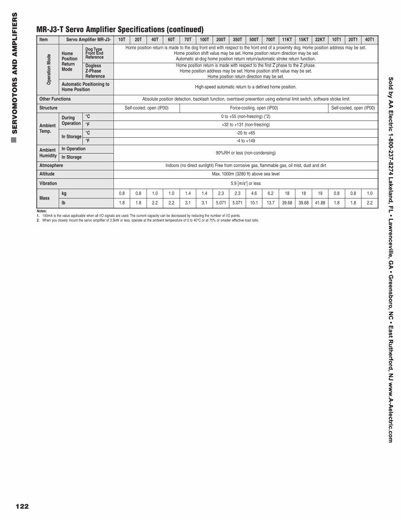
122
n
SE
RV
OM
OT
OR
S A
ND
AM
PL
IFIE
RS
Item Servo Amplifier MR-J3- 10T 20T 40T 60T 70T 100T 200T 350T 500T 700T 11KT 15KT 22KT 10T1 20T1 40T1
Ope
ratio
nM
ode Home
PositionReturnMode
Dog Type Front EndReference
Home position return is made to the dog front end with respect to the front end of a proximity dog. Home position address may be set.Home position shift value may be set. Home position return direction may be set.Automatic at-dog home position return return/automatic stroke return function.
Dogless Z-PhaseReference
Home position return is made with respect to the first Z phase to the Z phase.Home position address may be set. Home position shift value may be set.
Home position return direction may be set.
Automatic Positioning toHome Position High-speed automatic return to a defined home position.
Other Functions Absolute position detection, backlash function, overtravel prevention using external limit switch, software stroke limit
Structure Self-cooled, open (IP00) Force-cooling, open (IP00) Self-cooled, open (IP00)
AmbientTemp.
DuringOperation
°C 0 to +55 (non-freezing) (*2)
°F +32 to +131 (non-freezing)
In Storage°C -20 to +65
°F -4 to +149
AmbientHumidity
In Operation90%RH or less (non-condensing)
In Storage
Atmosphere Indoors (no direct sunlight) Free from corrosive gas, flammable gas, oil mist, dust and dirt
Altitude Max. 1000m (3280 ft) above sea level
Vibration 5.9 [m/s2] or less
Masskg 0.8 0.8 1.0 1.0 1.4 1.4 2.3 2.3 4.6 6.2 18 18 19 0.8 0.8 1.0
lb 1.8 1.8 2.2 2.2 3.1 3.1 5.071 5.071 10.1 13.7 39.68 39.68 41.88 1.8 1.8 2.2
Notes:1. 150mA is the value applicable when all I/O signals are used. The current capacity can be decreased by reducing the number of I/O points.2. When you closely mount the servo amplifier of 3.5kW or less, operate at the ambient temperature of 0 to 40°C or at 75% or smaller effective load ratio.
MR-J3-T Servo Amplifier Specifications (continued)
Sold by AA
Electric 1-800-237-8274 Lakeland, FL • Lawrenceville, G
A • G
reensboro, NC
• East Rutherford, N
J ww
w.A
-Aelectric.com
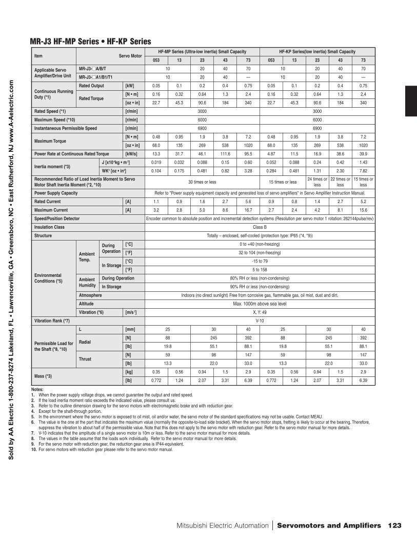
Mitsubishi Electric Automation | Servomotors and Amplifiers 123
Item Servo Motor HF-MP Series (Ultra-low inertia) Small Capacity HF-KP Series(low inertia) Small Capacity
053 13 23 43 73 053 13 23 43 73
Applicable ServoAmplifier/Drive Unit
MR-J3-nnA/B/T 10 20 40 70 10 20 40 70
MR-J3-nnA1/B1/T1 10 20 40 — 10 20 40 —
Continuous RunningDuty (*1)
Rated Output [kW] 0.05 0.1 0.2 0.4 0.75 0.05 0.1 0.2 0.4 0.75
Rated Torque [N • m] 0.16 0.32 0.64 1.3 2.4 0.16 0.32 0.64 1.3 2.4
[oz • in] 22.7 45.3 90.6 184 340 22.7 45.3 90.6 184 340
Rated Speed (*1) [r/min] 3000 3000
Maximum Speed (*10) [r/min] 6000 6000
Instantaneous Permissible Speed [r/min] 6900 6900
Maximum Torque [N • m] 0.48 0.95 1.9 3.8 7.2 0.48 0.95 1.9 3.8 7.2
[oz • in] 68.0 135 269 538 1020 68.0 135 269 538 1020
Power Rate at Continuous Rated Torque [kW/s] 13.3 31.7 46.1 111.6 95.5 4.87 11.5 16.9 38.6 39.9
Inertia moment (*3) J [x10-4kg • m 2] 0.019 0.032 0.088 0.15 0.60 0.052 0.088 0.24 0.42 1.43
WK2 [oz • in2] 0.104 0.175 0.481 0.82 3.28 0.284 0.481 1.31 2.30 7.82
Recommended Ratio of Load Inertia Moment to ServoMotor Shaft Inertia Moment (*2, *10)
30 times or less 15 times or less 24 times or
less 22 times or
less 15 times or
less
Power Supply Capacity Refer to "Power supply equipment capacity and generated loss of servo amplifiers" in Servo Amplifier Instruction Manual.
Rated Current [A] 1.1 0.9 1.6 2.7 5.6 0.9 0.8 1.4 2.7 5.2
Maximum Current [A] 3.2 2.8 5.0 8.6 16.7 2.7 2.4 4.2 8.1 15.6
Speed/Position Detector Encoder common to absolute position and incremental detection systems (Resolution per servo motor 1 rotation: 262144pulse/rev)
Insulation Class Class B
Structure Totally – enclosed, self-cooled (protection type: IP65 (*4, *9))
EnvironmentalConditions (*5)
AmbientTemp.
DuringOperation
[°C] 0 to +40 (non-freezing)
[°F] 32 to 104 (non-freezing)
In Storage[°C] -15 to 79
[°F] 5 to 158
AmbientHumidity
During Operation 80% RH or less (non-condensing)
In Storage 90% RH or less (non-condensing)
Atmosphere Indoors (no direct sunlight) Free from corrosive gas, flammable gas, oil mist, dust and dirt.
Altitude Max. 1000m above sea level
Vibration (*6) [m/s 2] X, Y: 49
Vibration Rank (*7) V-10
Permissible Load forthe Shaft (*8, *10)
L [mm] 25 30 40 25 30 40
Radial [N] 88 245 392 88 245 392
[lb] 19.8 55.1 88.1 19.8 55.1 88.1
Thrust [N] 59 98 147 59 98 147
[lb] 13.3 22.0 33.0 13.3 22.0 33.0
Mass (*3) [kg] 0.35 0.56 0.94 1.5 2.9 0.35 0.56 0.94 1.5 2.9
[lb] 0.772 1.24 2.07 3.31 6.39 0.772 1.24 2.07 3.31 6.39
Notes:1. When the power supply voltage drops, we cannot guarantee the output and rated speed.2. If the load inertia moment ratio exceeds the indicated value, please consult us.3. Refer to the outline dimension drawing for the servo motors with electromagnetic brake and with reduction gear.4. Except for the shaft-through portion.5. In the environment where the servo motor is exposed to oil mist, oil and/or water, the servo motor of the standard specifications may not be usable. Contact MEAU.6. The value is the one at the part that indicates the maximum value (normally the opposite-to-load side bracket). When the servo motor stops, fretting is likely to occur at the bearing. Therefore,
suppress the vibration to about half of the permissible value. Note that this does not apply to the servo motor with reduction gear. Refer to the servo motor manual for more details.7. V-10 indicates that the amplitude of a single servo motor is 10m or less. Refer to the servo motor manual for more details.8. The values in the table assume that the loads work individually. Refer to the servo motor manual for more details.9. For the servo motor with reduction gear, the reduction gear area is IP44-equivalent.10. For servo motors with reduction gear please refer to the servo motor manual.
MR-J3 HF-MP Series • HF-KP Series
Sold
by
AA
Ele
ctric
1-8
00-2
37-8
274
Lake
land
, FL
• Law
renc
evill
e, G
A •
Gre
ensb
oro,
NC
• Ea
st R
uthe
rfor
d, N
J w
ww
.A-A
elec
tric
.com
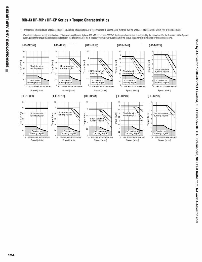
124
n
SE
RV
OM
OT
OR
S A
ND
AM
PL
IFIE
RS
MR-J3 HF-MP / HF-KP Series • Torque Characteristics
• For machines which produce unbalanced torque, e.g. vertical lift applications, it is recommended to use the servo motor so that the unbalanced torque will be within 70% of the rated torque.
• When the input power supply specifications of the servo amplifier are 3-phase 200 VAC or 1-phase 230 VAC, the torque characteristic is indicated by the heavy line. For the 1-phase 100 VAC powersupply, part of the torque characteristic is indicated by the broken line. For the 1-phase 200 VAC power supply, part of the torque characteristic is indicated by the continuous line.
Sold by AA
Electric 1-800-237-8274 Lakeland, FL • Lawrenceville, G
A • G
reensboro, NC
• East Rutherford, N
J ww
w.A
-Aelectric.com
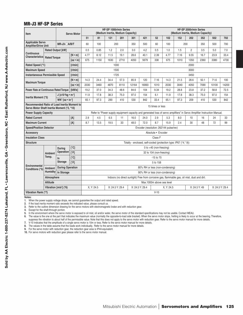
Mitsubishi Electric Automation | Servomotors and Amplifiers 125
Item Servo MotorHF-SP 1000r/min Series
(Medium Inertia, Medium Capacity) HF-SP 2000r/min Series
(Medium Inertia, Medium Capacity)
51 81 121 201 301 421 52 102 152 202 352 502 702 Applicable Servo Amplifier/Drive Unit MR-J3-nnA/B/T 60 100 200 350 500 60 100 200 350 500 700
ContinuousCharacteristics
Rated Output [kW] 0.5 0.85 1.2 2.0 3.0 4.2 0.5 1.0 1.5 2 3.5 5.0 7.0
Rated Torque [N • m] 4.77 8.12 11.5 19.1 28.6 40.1 2.39 4.77 7.16 9.55 16.7 23.9 33.4
[oz • in] 675 1150 1630 2710 4050 5679 338 675 1010 1350 2360 3380 4730
Rated Speed (*1) [r/min] 1000 2000
Maximum Speed [r/min] 1500 3000
Instantaneous Permissible Speed [r/min] 1725 3450
Maximum Torque [N • m] 14.3 24.4 34.4 57.3 85.9 120 7.16 14.3 21.5 28.6 50.1 71.6 100
[oz • in] 2030 3460 4870 8110 12164 16993 1010 2030 3040 4050 7090 10100 14200
Power Rate at Continuous Rated Torque [kW/s] 19.2 37.0 34.3 48.6 84.6 104 9.34 19.2 28.8 23.8 37.2 58.8 72.5
Inertia Moment (*3) J [x10-4kg • m 2] 11.9 17.8 38.3 75.0 97.0 154 6.1 11.9 17.8 38.3 75.0 97.0 154
WK2 [oz • in 2] 65.1 97.3 290 410 530 842 33.4 65.1 97.3 209 410 530 842
Recommended Ratio of Load Inertia Moment toServo Motor Shaft Inertia Moment (*2, *10) 15 times or less
Power Supply Capacity Refer to “Power supply equipment capacity and generated loss of servo amplifiers” in Servo Amplifier Instruction Manual.
Rated Current [A] 2.9 4.5 6.5 11 16.0 24.0 2.9 5.3 8.0 10 16 24 33
Maximum Current [A] 8.7 13.5 19.5 33 48.0 72.0 8.7 15.9 2.4 30 48 72 99
Speed/Position Detector Encoder (resolution: 262144 pulse/rev)
Accessory Absolute • Encoder
Insulation Class Class F
Structure Totally - enclosed, self-cooled (protection type: IP67 (*4,* 9))
EnvironmentalConditions (*5)
AmbientTemp.
DuringOperation
[°C] 0 to +40 (non-freezing)
[°F] 32 to 104 (non-freezing)
InStorage
[°C] -15 to 70
[°F] 5 to 158
AmbientHumidity
During Operation 80% RH or less (non-condensing)
In Storage 90% RH or less (non-condensing)
Atmosphere Indoors (no direct sunlight) Free from corrosive gas, flammable gas, oil mist, dust and dirt.
Altitude Max.1000m above sea level
Vibration [m/s2] (*6) X, Y: 24.5 X: 24.5 Y: 29.4 X: 24.5 Y: 29.4 X, Y: 24.5 X: 24.5 Y: 49 X: 24.5 Y: 29.4
Vibration Rank (*7) V-10
MR-J3 HF-SP Series
Notes:1. When the power supply voltage drops, we cannot guarantee the output and rated speed.2. If the load inertia moment ratio exceeds the indicated value, please consult us.3. Refer to the outline dimension drawing for the servo motors with electromagnetic brake and with reduction gear.4. Except for the shaft-through portion.5. In the environment where the servo motor is exposed to oil mist, oil and/or water, the servo motor of the standard specifications may not be usable. Contact MEAU.6. The value is the one at the part that indicates the maximum value (normally the opposite-to-load side bracket). When the servo motor stops, fretting is likely to occur at the bearing. Therefore,
suppress the vibration to about half of the permissible value. Note that this does not apply to the servo motor with reduction gear. Refer to the servo motor manual for more details.7. V-10 indicates that the amplitude of a single servo motor is 10m or less. Refer to the servo motor manual for more details.8. The values in the table assume that the loads work individually. Refer to the servo motor manual for more details.9. For the servo motor with reduction gear, the reduction gear area is IP44-equivalent.10. For servo motors with reduction gear please refer to the servo motor manual.
Sold
by
AA
Ele
ctric
1-8
00-2
37-8
274
Lake
land
, FL
• Law
renc
evill
e, G
A •
Gre
ensb
oro,
NC
• Ea
st R
uthe
rfor
d, N
J w
ww
.A-A
elec
tric
.com
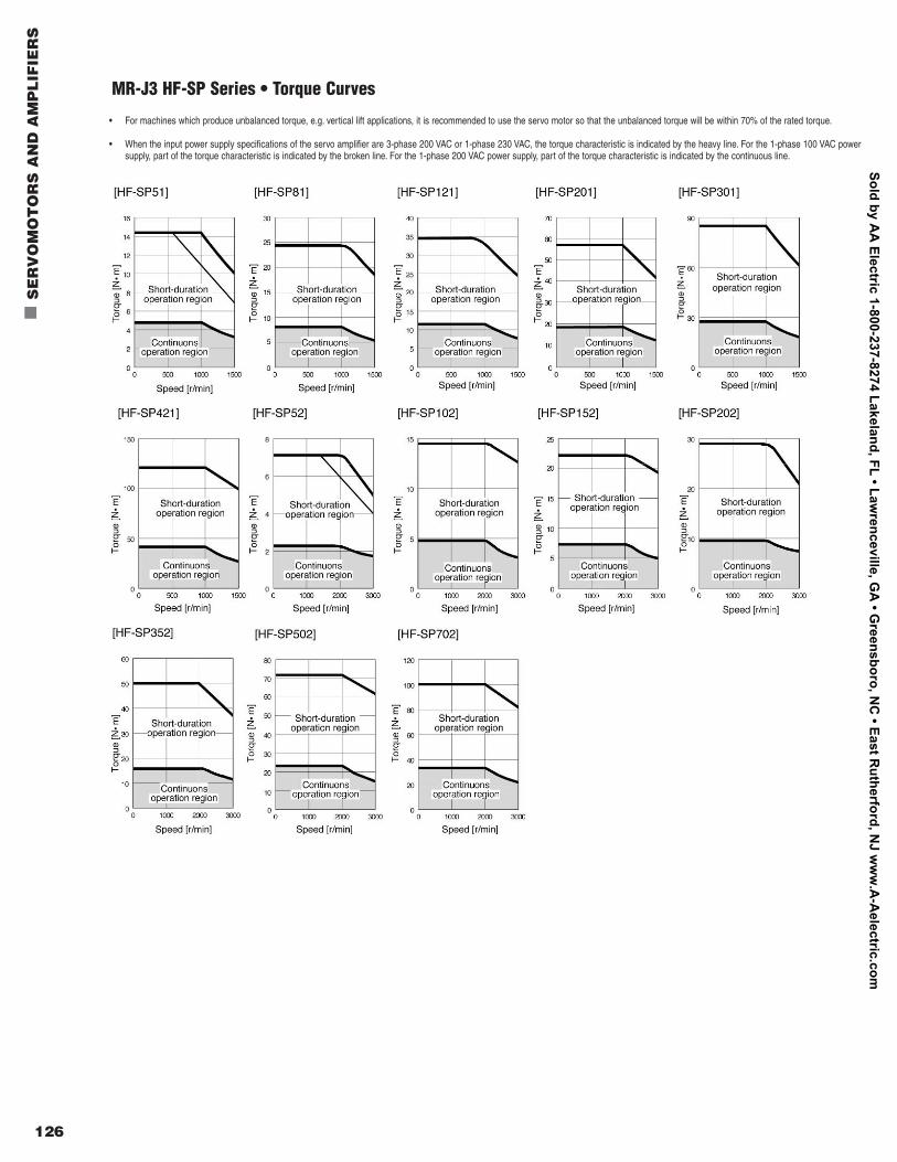
126
n
SE
RV
OM
OT
OR
S A
ND
AM
PL
IFIE
RS
MR-J3 HF-SP Series • Torque Curves
• For machines which produce unbalanced torque, e.g. vertical lift applications, it is recommended to use the servo motor so that the unbalanced torque will be within 70% of the rated torque.
• When the input power supply specifications of the servo amplifier are 3-phase 200 VAC or 1-phase 230 VAC, the torque characteristic is indicated by the heavy line. For the 1-phase 100 VAC powersupply, part of the torque characteristic is indicated by the broken line. For the 1-phase 200 VAC power supply, part of the torque characteristic is indicated by the continuous line.
Sold by AA
Electric 1-800-237-8274 Lakeland, FL • Lawrenceville, G
A • G
reensboro, NC
• East Rutherford, N
J ww
w.A
-Aelectric.com
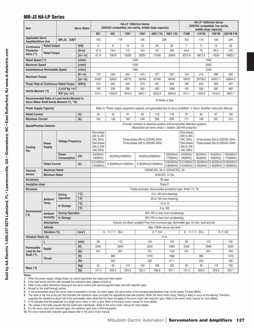
Mitsubishi Electric Automation | Servomotors and Amplifiers 127
MR-J3 HA-LP Series
Item Servo Motor HA-LP 1000r/min Series
(200VAC-compatible, low inertia, middle large capacity)
HA-LP 1500r/min Series (200VAC-compatible, low inertia
middle large capacity)601 801 12K1 15K1 20K1 (*8) 25K1 (*8) 710M 11K1M 15K1M 22K1M (*8)
Applicable ServoAmplifier/Drive Unit MR-J3-nnA/B/T 700 11K 15K 22K 700 11K 15K 22K
ContinuousCharacter-istics (*1)
Rated Output [kW] 6 8 12 15 20 25 7 11 15 22
Rated Torque [N•m] 57.3 76.4 115 143 191 239 44.6 70 95.5 140
[oz • in] 8114 10819 16285 20251 27048 33845 6315.9 9912.9 13524 19825.7
Rated Speed (*1) [r/min] 1000 1500
Maximum Speed [r/min] 1200 2000
Instantaneous Permissible Speed [r/min] 1380 2300
Maximum Torque [N • m] 172 229 344 415 477 597 134 210 286 350
[oz • in] 24357 32429 48715 58769 67549 84542 18976 29738.6 40501.1 49564.3
Power Rate at Continuous Rated Torque [kW/s] 313 265 445 373 561 528 189 223 309 357
Inertia Moment (*3) J [x10-4kg • m 2] 105 220 295 550 650 1080 105 220 295 550
WK2 [oz • in2] 574.1 1202.8 1612.9 3007.1 3553.8 5904.8 574.1 1202.8 1612.9 3007.1
Recommended Ratio of Load Inertia Moment to Servo Motor Shaft Inertia Moment (*2, *10) 10 times or less
Power Supply Capacity Refer to “Power supply equipment capacity and generated loss of servo amplifiers” in Servo Amplifier Instruction Manual.
Rated Current [A] 34 42 61 83 118 118 37 65 87 126
Maximum Current [A] 102 126 183 249 295 295 111 195 261 315
Speed/Position Detector Encoder common to absolute position and incremental detection systems (Resolution per servo motor 1 rotation: 262144 pulse/rev)
Cooling Fan
PowerSupply
Voltage Frequency
One-phase200 to 220VAC 50Hz,One-phase200 to 230VAC 60Hz
Three-phase 200 to 220VAC 50Hz Three-phase 200 to 230VAC 60Hz
One-phase200 to 220VAC 50Hz,One-phase200 to 230VAC 60Hz
Three-phase 200 to 220VAC 50Hz Three-phase 200 to 230VAC 60Hz
PowerConsumption [W] 42(50Hz)/
54(60Hz) 32(50Hz)/40(60Hz) 45(50Hz)/63(60Hz) 120(50Hz)/175(60Hz)
42(50Hz)/54(60Hz)
32(50Hz)/40(60Hz)
45(50Hz)/63(60Hz)
120(50Hz)/175(60Hz)
Rated Current [A] 0.21(50Hz)/0.25(60Hz) 0.30(50Hz)/0.25(60Hz) 0.32(50Hz)/0.35(60Hz) 0.65(50Hz)/
0.80(60Hz) 0.21(50Hz)/0.25(60Hz)
0.30(50Hz)/0.25(60Hz)
0.32(50Hz)/0.35(60Hz)
0.65(50Hz)/0.80(60Hz)
ThermalSensor
Maximum Rated 125VAC/DC, 3A or 250VAC/DC, 2A
Minimum Rated 6VAC/DC, 0.15A
Accessory Oil seal
Insulation class Class F
Structure Totally-enclosed, force-cooled (protection type: IP44) (*4, *9)
Environment(*4)
AmbientTemp.
DuringOperation
[°C] 0 to +40 (non-freezing)
[°F] 32 to 104 (non-freezing)
In Storage[°C] -15 to 70
[°F] 5 to 158
Ambient Humidity
During Operation 80% RH or less (non-condensing)
In Storage 90% RH or less (non-condensing)
Atmosphere Indoors (no direct sunlight) Free from corrosive gas, flammable gas, oil mist, dust and dirt.
Altitude Max.1000m above sea level
Vibration (*5) [m/s2] X, : 11.7, Y : 29.4 X, Y: 9.8 X, : 11.7, Y : 29.4 X, Y: 9.8
Vibration Rank (*6) V-10
PermissibleLoad for theShaft (*7)
L [mm] 85 110 140 140 85 110 140
Radial [N] 2450 2940 3234 4900 2450 2940 3234
[lb] 551 661 727 1102 551 661 794
Thrust [N] 980 1470 1960 980 1470
[lb] 220 330 51.7 220 330
Mass (*3) [kg] 55 95 115 160 180 230 55 95 115 160
[lb] 121.3 209.4 253.5 352.7 396.8 507.1 121.3 209.4 253.5 352.7
Notes:1. When the power supply voltage drops, we cannot guarantee the output and rated speed.2. If the load inertia moment ratio exceeds the indicated value, please consult us.3. Refer to the outline dimension drawing for the servo motors with electromagnetic brake and with reduction gear.4. Except for the shaft-through portion.5. In the environment where the servo motor is exposed to oil mist, oil and/or water, the servo motor of the standard specifications may not be usable. Contact MEAU.6. The value is the one at the part that indicates the maximum value (normally the opposite-to-load side bracket). When the servo motor stops, fretting is likely to occur at the bearing. Therefore,
suppress the vibration to about half of the permissible value. Note that this does not apply to the servo motor with reduction gear. Refer to the servo motor manual for more details.7. V-10 indicates that the amplitude of a single servo motor is 10m or less. Refer to the servo motor manual for more details.8. The values in the table assume that the loads work individually. Refer to the servo motor manual for more details.9. For the servo motor with reduction gear, the reduction gear area is IP44-equivalent.10. For servo motors with reduction gear please refer to the servo motor manual.
Sold
by
AA
Ele
ctric
1-8
00-2
37-8
274
Lake
land
, FL
• Law
renc
evill
e, G
A •
Gre
ensb
oro,
NC
• Ea
st R
uthe
rfor
d, N
J w
ww
.A-A
elec
tric
.com
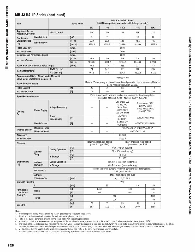
128
n
SE
RV
OM
OT
OR
S A
ND
AM
PL
IFIE
RS
MR-J3 HA-LP Series (continued)
Item Servo Motor HA-LP 2000r/min Series
(200VAC-compatible, low inertia, middle large capacity)
502 702 11K2 15K2 22K2Applicable Servo Amplifier/Drive Unit MR-J3-nnA/B/T 500 700 11K 15K 22K
ContinuousCharacteristics(*1)
Rated Output [kW] 5 7 11 15 22
Rated Torque [N • m] 23.9 33.4 52.5 71.6 105
[oz • in] 3384.5 4729.9 7434.6 10139.4 14869.3
Rated Speed (*1) [r/min] 2000
Maximum Speed [r/min] 2000
Instantaneous Permissible Speed [r/min] 2300
Maximum Torque [N • m] 71.6 100 158 215 263
[oz • in] 10139.4 14161.2 22374.7 30446.6 37244
Power Rate at Continuous Rated Torque [kW/s] 77.2 118 263 233 374
Inertia Moment (*3) J [x10-4kg • m 2] 74 94.2 105 220 295
WK2 [oz • in2] 404.6 515 574.1 1202.8 1612.9
Recommended Ratio of Load Inertia Moment to Servo Motor Shaft Inertia Moment (*2) 10 times or less
Power Supply Capacity Refer to “Power supply equipment capacity and generated loss of servo amplifiers” in Servo Amplifier Instruction Manual.
Rated Current [A] 25 34 63 77 112
Maximum Current [A] 75 102 189 231 280
Speed/Position Detector Encoder common to absolute position and incremental detection systems (Resolution per servo motor 1 rotation: 262144 pulse/rev)
Cooling Fan
Power Supply Voltage Frequency — —
One-phase 200to 220 VAC50Hz, One-
phase 200 to230 VAC 60Hz
Three-phase 200 to 220VAC 50Hz
Three-phase 200 to 230VAC 60Hz
PowerConsumption [W] — — 42(50Hz)/
54(60Hz) 32(50Hz)/40(60Hz)
Rated Current [A] — — 0.21(50Hz)/0.25(60Hz) 0.30(50Hz)/0.25(60Hz)
Thermal Sensor Maximum Rated — — 125VAC/DC, 3A or 250VAC/DC, 2A
Minimum Rated — — 6VAC/DC, 0.15A
Accessory Oil seal
Insulation class Class F
Structure Totally-enclosed, self-cooled (protection type: IP65)
Totally-enclosed, force-cooled (protection type: IP44)
Environment(*4)
AmbientTemp.
During Operation[°C] 0 to +40 (non-freezing)
[°F] 32 to 104 (non-freezing)
In Storage[°C] -15 to 70
[°F] 5 to 158
Ambient Humidity
During Operation 80% RH or less (non-condensing)
In Storage 90% RH or less (non-condensing)
Atmosphere Indoors (no direct sunlight) Free from corrosive gas, flammable gas, oil mist, dust and dirt.
Altitude Max.1000m above sea level
Vibration (*5) [m/s2] X, : 11.7, Y : 29.4
Vibration Rank (*6) V-10
PermissibleLoad for theShaft (*7)
L [mm] 85 110 140
Radial [N] 2450 2940 3234
[lb] 551 661 727
Thrust [N] 980 1470
[lb] 220 330
Mass (*3) [kg] 28 35 55 95 115
[lb] 61.7 77.2 121.3 209.4 253.5
Notes:1. When the power supply voltage drops, we cannot guarantee the output and rated speed.2. If the load inertia moment ratio exceeds the indicated value, please consult us.3. Refer to the outline dimension drawing for the servo motor with electromagnetic brake.4. In the environment where the servo motor is exposed to oil mist, oil and/or water, the servo motor of the standard specifications may not be usable. Contact MEAU.5. The value is the one at the part that indicates the maximum value (normally the opposite-to-load side bracket). When the servo motor stops, fretting is likely to occur at the bearing. Therefore,
suppress the vibration to about half of the permissible value. Note that this does not apply to the servo motor with reduction gear. Refer to the servo motor manual for more details.6. V-10 indicates that the amplitude of a single servo motor is 10m or less. Refer to the servo motor manual for more details.7. The values in the table assume that the loads work individually. Refer to the servo motor manual for more details.
Sold by AA
Electric 1-800-237-8274 Lakeland, FL • Lawrenceville, G
A • G
reensboro, NC
• East Rutherford, N
J ww
w.A
-Aelectric.com
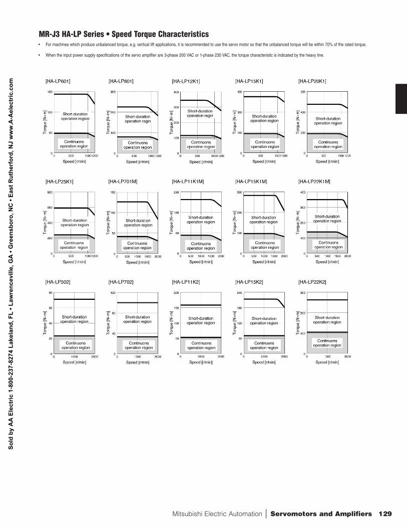
Mitsubishi Electric Automation | Servomotors and Amplifiers 129
MR-J3 HA-LP Series • Speed Torque Characteristics• For machines which produce unbalanced torque, e.g. vertical lift applications, it is recommended to use the servo motor so that the unbalanced torque will be within 70% of the rated torque.
• When the input power supply specifications of the servo amplifier are 3-phase 200 VAC or 1-phase 230 VAC, the torque characteristic is indicated by the heavy line.
Sold
by
AA
Ele
ctric
1-8
00-2
37-8
274
Lake
land
, FL
• Law
renc
evill
e, G
A •
Gre
ensb
oro,
NC
• Ea
st R
uthe
rfor
d, N
J w
ww
.A-A
elec
tric
.com
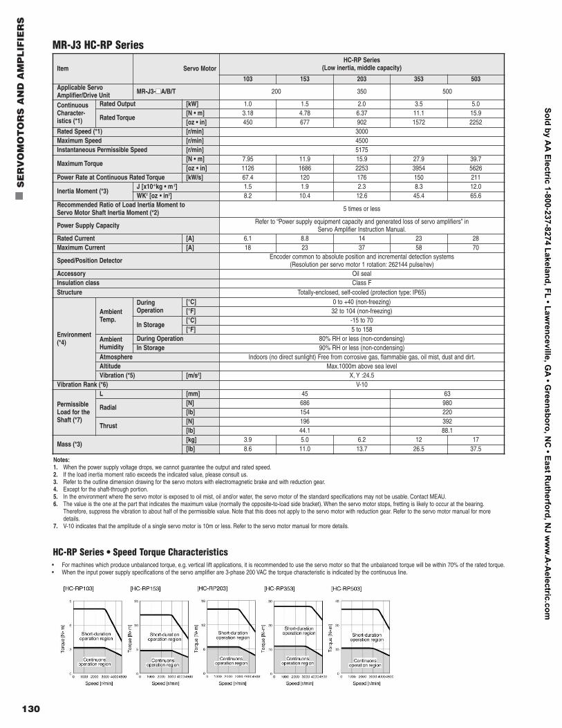
130
n
SE
RV
OM
OT
OR
S A
ND
AM
PL
IFIE
RS
MR-J3 HC-RP Series
Item Servo Motor HC-RP Series
(Low inertia, middle capacity)
103 153 203 353 503Applicable ServoAmplifier/Drive Unit MR-J3-nnA/B/T 200 350 500
ContinuousCharacter-istics (*1)
Rated Output [kW] 1.0 1.5 2.0 3.5 5.0
Rated Torque [N • m] 3.18 4.78 6.37 11.1 15.9[oz • in] 450 677 902 1572 2252
Rated Speed (*1) [r/min] 3000 Maximum Speed [r/min] 4500 Instantaneous Permissible Speed [r/min] 5175
Maximum Torque [N • m] 7.95 11.9 15.9 27.9 39.7[oz • in] 1126 1686 2253 3954 5626
Power Rate at Continuous Rated Torque [kW/s] 67.4 120 176 150 211
Inertia Moment (*3) J [x10-4kg • m 2] 1.5 1.9 2.3 8.3 12.0WK2 [oz • in2] 8.2 10.4 12.6 45.4 65.6
Recommended Ratio of Load Inertia Moment to Servo Motor Shaft Inertia Moment (*2) 5 times or less
Power Supply Capacity Refer to “Power supply equipment capacity and generated loss of servo amplifiers” in Servo Amplifier Instruction Manual.
Rated Current [A] 6.1 8.8 14 23 28Maximum Current [A] 18 23 37 58 70
Speed/Position Detector Encoder common to absolute position and incremental detection systems (Resolution per servo motor 1 rotation: 262144 pulse/rev)
Accessory Oil seal Insulation class Class F Structure Totally-enclosed, self-cooled (protection type: IP65)
Environment(*4)
AmbientTemp.
DuringOperation
[°C] 0 to +40 (non-freezing) [°F] 32 to 104 (non-freezing)
In Storage[°C] -15 to 70[°F] 5 to 158
Ambient Humidity
During Operation 80% RH or less (non-condensing) In Storage 90% RH or less (non-condensing)
Atmosphere Indoors (no direct sunlight) Free from corrosive gas, flammable gas, oil mist, dust and dirt.Altitude Max.1000m above sea level Vibration (*5) [m/s2] X, Y :24.5
Vibration Rank (*6) V-10
PermissibleLoad for theShaft (*7)
L [mm] 45 63
Radial [N] 686 980[lb] 154 220
Thrust [N] 196 392[lb] 44.1 88.1
Mass (*3) [kg] 3.9 5.0 6.2 12 17[lb] 8.6 11.0 13.7 26.5 37.5
HC-RP Series • Speed Torque Characteristics• For machines which produce unbalanced torque, e.g. vertical lift applications, it is recommended to use the servo motor so that the unbalanced torque will be within 70% of the rated torque.• When the input power supply specifications of the servo amplifier are 3-phase 200 VAC the torque characteristic is indicated by the continuous line.
Notes:1. When the power supply voltage drops, we cannot guarantee the output and rated speed.2. If the load inertia moment ratio exceeds the indicated value, please consult us.3. Refer to the outline dimension drawing for the servo motors with electromagnetic brake and with reduction gear.4. Except for the shaft-through portion.5. In the environment where the servo motor is exposed to oil mist, oil and/or water, the servo motor of the standard specifications may not be usable. Contact MEAU.6. The value is the one at the part that indicates the maximum value (normally the opposite-to-load side bracket). When the servo motor stops, fretting is likely to occur at the bearing.
Therefore, suppress the vibration to about half of the permissible value. Note that this does not apply to the servo motor with reduction gear. Refer to the servo motor manual for moredetails.
7. V-10 indicates that the amplitude of a single servo motor is 10m or less. Refer to the servo motor manual for more details.
Sold by AA
Electric 1-800-237-8274 Lakeland, FL • Lawrenceville, G
A • G
reensboro, NC
• East Rutherford, N
J ww
w.A
-Aelectric.com
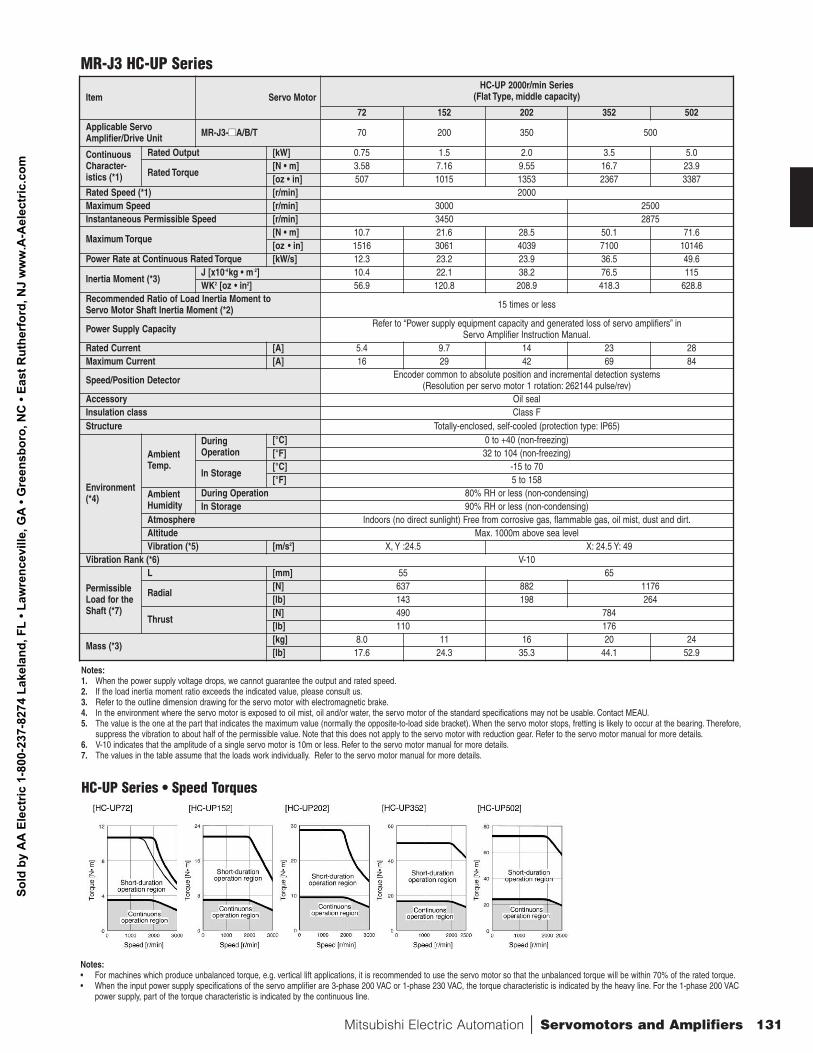
Mitsubishi Electric Automation | Servomotors and Amplifiers 131
MR-J3 HC-UP Series
Item Servo Motor HC-UP 2000r/min Series
(Flat Type, middle capacity)
72 152 202 352 502Applicable ServoAmplifier/Drive Unit MR-J3-nnA/B/T 70 200 350 500
ContinuousCharacter-istics (*1)
Rated Output [kW] 0.75 1.5 2.0 3.5 5.0
Rated Torque [N • m] 3.58 7.16 9.55 16.7 23.9[oz • in] 507 1015 1353 2367 3387
Rated Speed (*1) [r/min] 2000 Maximum Speed [r/min] 3000 2500Instantaneous Permissible Speed [r/min] 3450 2875
Maximum Torque [N • m] 10.7 21.6 28.5 50.1 71.6[oz • in] 1516 3061 4039 7100 10146
Power Rate at Continuous Rated Torque [kW/s] 12.3 23.2 23.9 36.5 49.6
Inertia Moment (*3) J [x10-4kg • m 2] 10.4 22.1 38.2 76.5 115WK2 [oz • in2] 56.9 120.8 208.9 418.3 628.8
Recommended Ratio of Load Inertia Moment to Servo Motor Shaft Inertia Moment (*2) 15 times or less
Power Supply Capacity Refer to “Power supply equipment capacity and generated loss of servo amplifiers” in Servo Amplifier Instruction Manual.
Rated Current [A] 5.4 9.7 14 23 28Maximum Current [A] 16 29 42 69 84
Speed/Position Detector Encoder common to absolute position and incremental detection systems (Resolution per servo motor 1 rotation: 262144 pulse/rev)
Accessory Oil seal Insulation class Class F Structure Totally-enclosed, self-cooled (protection type: IP65)
Environment(*4)
AmbientTemp.
DuringOperation
[°C] 0 to +40 (non-freezing) [°F] 32 to 104 (non-freezing)
In Storage[°C] -15 to 70[°F] 5 to 158
Ambient Humidity
During Operation 80% RH or less (non-condensing) In Storage 90% RH or less (non-condensing)
Atmosphere Indoors (no direct sunlight) Free from corrosive gas, flammable gas, oil mist, dust and dirt.Altitude Max. 1000m above sea level Vibration (*5) [m/s2] X, Y :24.5 X: 24.5 Y: 49
Vibration Rank (*6) V-10
PermissibleLoad for theShaft (*7)
L [mm] 55 65
Radial [N] 637 882 1176[lb] 143 198 264
Thrust [N] 490 784[lb] 110 176
Mass (*3) [kg] 8.0 11 16 20 24[lb] 17.6 24.3 35.3 44.1 52.9
HC-UP Series • Speed Torques
Notes:• For machines which produce unbalanced torque, e.g. vertical lift applications, it is recommended to use the servo motor so that the unbalanced torque will be within 70% of the rated torque.• When the input power supply specifications of the servo amplifier are 3-phase 200 VAC or 1-phase 230 VAC, the torque characteristic is indicated by the heavy line. For the 1-phase 200 VAC
power supply, part of the torque characteristic is indicated by the continuous line.
Notes:1. When the power supply voltage drops, we cannot guarantee the output and rated speed.2. If the load inertia moment ratio exceeds the indicated value, please consult us.3. Refer to the outline dimension drawing for the servo motor with electromagnetic brake.4. In the environment where the servo motor is exposed to oil mist, oil and/or water, the servo motor of the standard specifications may not be usable. Contact MEAU.5. The value is the one at the part that indicates the maximum value (normally the opposite-to-load side bracket). When the servo motor stops, fretting is likely to occur at the bearing. Therefore,
suppress the vibration to about half of the permissible value. Note that this does not apply to the servo motor with reduction gear. Refer to the servo motor manual for more details.6. V-10 indicates that the amplitude of a single servo motor is 10m or less. Refer to the servo motor manual for more details.7. The values in the table assume that the loads work individually. Refer to the servo motor manual for more details.
Sold
by
AA
Ele
ctric
1-8
00-2
37-8
274
Lake
land
, FL
• Law
renc
evill
e, G
A •
Gre
ensb
oro,
NC
• Ea
st R
uthe
rfor
d, N
J w
ww
.A-A
elec
tric
.com
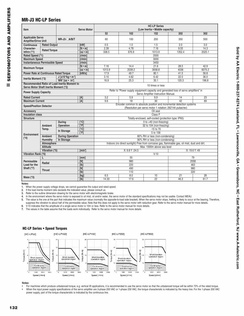
132
n
SE
RV
OM
OT
OR
S A
ND
AM
PL
IFIE
RS
MR-J3 HC-LP Series
Item Servo Motor HC-LP Series
(Low Inertia • Middle capacity)52 102 152 202 302
Applicable ServoAmplifier/Drive Unit MR-J3-nnA/B/T 60 100 200 350 500
ContinuousCharacter-istics (*1)
Rated Output [kW] 0.5 1.0 1.5 2.0 3.0
Rated Torque [N • m] 2.39 4.78 7.16 9.55 14.3[oz • in] 338.5 676.9 1013.9 1352.4 2025.1
Rated Speed (*1) [r/min] 2000 Maximum Speed [r/min] 3000 Instantaneous Permissible Speed [r/min] 3450
Maximum Torque [N • m] 7.16 14.4 21.6 28.5 42.9[oz • in] 1013.9 2039.2 3058.8 4036 6075.2
Power Rate at Continuous Rated Torque [kW/s] 17.9 49.7 80.1 41.5 56.8
Inertia Moment (*3) J [x10-4kg • m 2] 3.10 4.62 6.42 22.0 36.0WK2 [oz • in2] 16.9 25.3 35.1 120.3 196.8
Recommended Ratio of Load Inertia Moment to Servo Motor Shaft Inertia Moment (*2) 10 times or less
Power Supply Capacity Refer to “Power supply equipment capacity and generated loss of servo amplifiers” in Servo Amplifier Instruction Manual.
Rated Current [A] 3.2 5.9 9.9 14 23Maximum Current [A] 9.6 18 30 42 69
Speed/Position Detector Encoder common to absolute position and incremental detection systems (Resolution per servo motor 1 rotation: 262144 pulse/rev)
Accessory Oil seal Insulation class Class F Structure Totally-enclosed, self-cooled (protection type: IP65)
Environment(*4)
AmbientTemp.
DuringOperation
[°C] 0 to +40 (non-freezing) [°F] 32 to 104 (non-freezing)
In Storage [°C] -15 to 70[°F] 5 to 158
Ambient Humidity
During Operation 80% RH or less (non-condensing) In Storage 90% RH or less (non-condensing)
Atmosphere Indoors (no direct sunlight) Free from corrosive gas, flammable gas, oil mist, dust and dirt.Altitude Max. 1000m above sea level Vibration (*5) [m/s2] X: 9.8 Y :24.5 X: 19.6 Y: 49
Vibration Rank (*6) V-10
PermissibleLoad for theShaft (*7)
L [mm] 55 79
Radial [N] 980 2058[lb] 220 463
Thrust [N] 490 980[lb] 110 220
Mass (*3) [kg] 6.5 8.0 10 21 28[lb] 14.33 17.6 22 46.3 61.7
HC-LP Series • Speed Torques
Notes:• For machines which produce unbalanced torque, e.g. vertical lift applications, it is recommended to use the servo motor so that the unbalanced torque will be within 70% of the rated torque.• When the input power supply specifications of the servo amplifier are 3-phase 200 VAC or 1-phase 230 VAC, the torque characteristic is indicated by the heavy line. For the 1-phase 200 VAC
power supply, part of the torque characteristic is indicated by the continuous line.
Notes:1. When the power supply voltage drops, we cannot guarantee the output and rated speed.2. If the load inertia moment ratio exceeds the indicated value, please consult us.3. Refer to the outline dimension drawing for the servo motor with electromagnetic brake.4. In the environment where the servo motor is exposed to oil mist, oil and/or water, the servo motor of the standard specifications may not be usable. Contact MEAU.5. The value is the one at the part that indicates the maximum value (normally the opposite-to-load side bracket). When the servo motor stops, fretting is likely to occur at the bearing. Therefore,
suppress the vibration to about half of the permissible value. Note that this does not apply to the servo motor with reduction gear. Refer to the servo motor manual for more details.6. V-10 indicates that the amplitude of a single servo motor is 10m or less. Refer to the servo motor manual for more details.7. The values in the table assume that the loads work individually. Refer to the servo motor manual for more details.
Sold by AA
Electric 1-800-237-8274 Lakeland, FL • Lawrenceville, G
A • G
reensboro, NC
• East Rutherford, N
J ww
w.A
-Aelectric.com
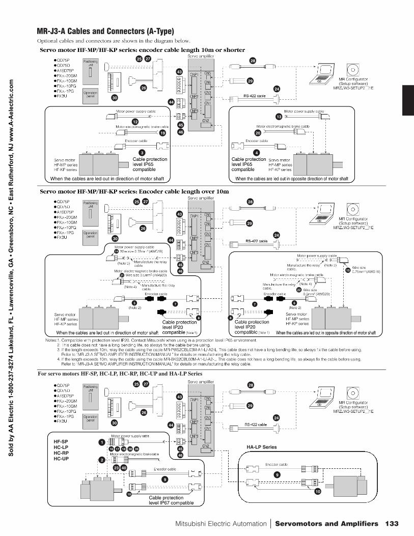
Mitsubishi Electric Automation | Servomotors and Amplifiers 133
30
26
27
43
44
45
46
43
44
45
46
43
44
45
46
27
24
25
24
28
29
12
19
3
13
20
4
25
26
30
28
29
30
26
2725
24
23 40
28
29
9
21
14
5
10
16 17 18 38 39
7
8 8
7
15
22
6
MR-J3-A Cables and Connectors (A-Type)
1
2
For servo motors HF-SP, HC-LP, HC-RP, HC-UP and HA-LP Series
HA-LP SeriesHF-SPHC-LPHC-RPHC-UP
10
9
Sold
by
AA
Ele
ctric
1-8
00-2
37-8
274
Lake
land
, FL
• Law
renc
evill
e, G
A •
Gre
ensb
oro,
NC
• Ea
st R
uthe
rfor
d, N
J w
ww
.A-A
elec
tric
.com
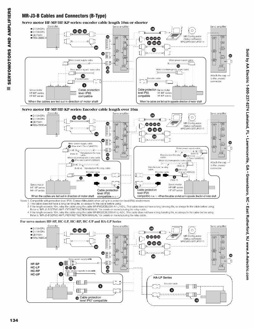
134
n
SE
RV
OM
OT
OR
S A
ND
AM
PL
IFIE
RS
34
43
45
46
44
43
45
46
44
43
45
46
44
31 32 33
31 32 33
28
34
12
19
3
13
36 37 47 48
35
20
4
36 37 47 48
31 32 33
34
28
34
31 32 33
32
29 30 31
23
2
1
28
31 32 33
34
9
21
8
14
5
10
16 17 18
7
8
7
15
35
35
36 37 47 48
22
6
MR-J3-B Cables and Connectors (B-Type)
For servo motors HF-SP, HC-LP, HC-RP, HC-UP and HA-LP Series
HA-LP Series
10
9
HF-SPHC-LPHC-RPHC-UP
Sold by AA
Electric 1-800-237-8274 Lakeland, FL • Lawrenceville, G
A • G
reensboro, NC
• East Rutherford, N
J ww
w.A
-Aelectric.com
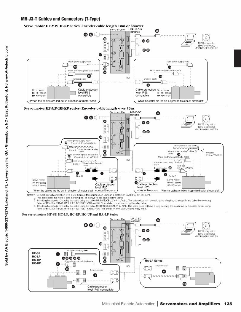
Mitsubishi Electric Automation | Servomotors and Amplifiers 135
4241
28
12
19
3
13
25 27
3643
45
46
44
43
45
46
44
43
45
46
44
37
20
4
28
4241
23
2
1
28
9
21
8
14
4241
5
10
16 17 18 38 39
7
8
7
15
21
6
MR-J3-T Cables and Connectors (T-Type)
HA-LP Series
10
9
For servo motors HF-SP, HC-LP, HC-RP, HC-UP and HA-LP Series
HF-SPHC-LPHC-RPHC-UP
25 27
36 37
25 27
36 37
D01
D01
D01
Sold
by
AA
Ele
ctric
1-8
00-2
37-8
274
Lake
land
, FL
• Law
renc
evill
e, G
A •
Gre
ensb
oro,
NC
• Ea
st R
uthe
rfor
d, N
J w
ww
.A-A
elec
tric
.com
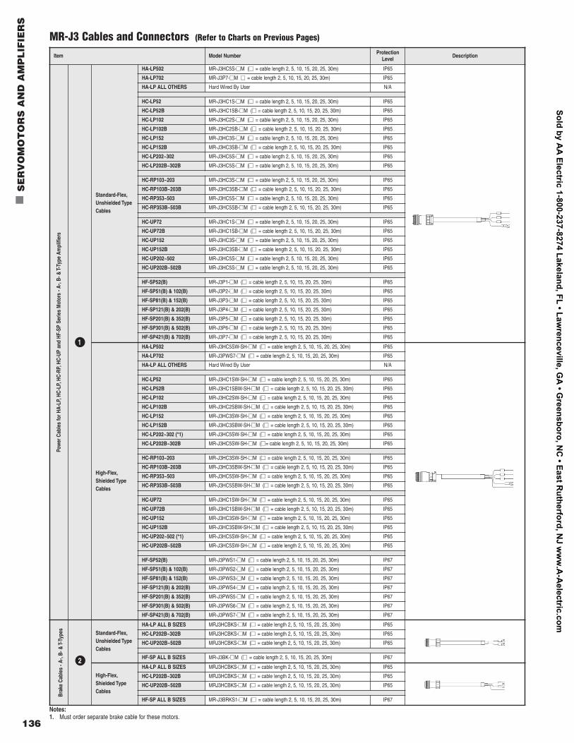
136
n
SE
RV
OM
OT
OR
S A
ND
AM
PL
IFIE
RS
MR-J3 Cables and Connectors (Refer to Charts on Previous Pages)
Notes:1. Must order separate brake cable for these motors.
Item Model Number ProtectionLevel Description
Pow
er C
able
s fo
r HA-
LP,H
C-LP
,HC-
RP,H
C-UP
and
HF-
SP S
erie
s M
otor
s - A
-,B-
& T-
Type
Am
plifi
ers
1
Standard-Flex,Unshielded TypeCables
HA-LP502 MR-J3HC5S-nnM (nn = cable length 2, 5, 10, 15, 20, 25, 30m) IP65
HA-LP702 MR-J3P7-nnM nn = cable length 2, 5, 10, 15, 20, 25, 30m) IP65
HA-LP ALL OTHERS Hard Wired By User N/A
HC-LP52 MR-J3HC1S-nnM (nn = cable length 2, 5, 10, 15, 20, 25, 30m) IP65
HC-LP52B MR-J3HC1SB-nnM (nn = cable length 2, 5, 10, 15, 20, 25, 30m) IP65
HC-LP102 MR-J3HC2S-nnM (nn = cable length 2, 5, 10, 15, 20, 25, 30m) IP65
HC-LP102B MR-J3HC2SB-nnM (nn = cable length 2, 5, 10, 15, 20, 25, 30m) IP65
HC-LP152 MR-J3HC3S-nnM (nn = cable length 2, 5, 10, 15, 20, 25, 30m) IP65
HC-LP152B MR-J3HC3SB-nnM (nn = cable length 2, 5, 10, 15, 20, 25, 30m) IP65
HC-LP202~302 MR-J3HC5S-nnM (nn = cable length 2, 5, 10, 15, 20, 25, 30m) IP65
HC-LP202B~302B MR-J3HC5S-nnM (nn = cable length 2, 5, 10, 15, 20, 25, 30m) IP65
HC-RP103~203 MR-J3HC3S-nnM (nn = cable length 2, 5, 10, 15, 20, 25, 30m) IP65
HC-RP103B~203B MR-J3HC3SB-nnM (nn = cable length 2, 5, 10, 15, 20, 25, 30m) IP65
HC-RP353~503 MR-J3HC5S-nnM (nn = cable length 2, 5, 10, 15, 20, 25, 30m) IP65
HC-RP353B~503B MR-J3HC5SB-nnM (nn = cable length 2, 5, 10, 15, 20, 25, 30m) IP65
HC-UP72 MR-J3HC1S-nnM (nn = cable length 2, 5, 10, 15, 20, 25, 30m) IP65
HC-UP72B MR-J3HC1SB-nnM (nn = cable length 2, 5, 10, 15, 20, 25, 30m) IP65
HC-UP152 MR-J3HC3S-nnM (nn = cable length 2, 5, 10, 15, 20, 25, 30m) IP65
HC-UP152B MR-J3HC3SB-nnM (nn = cable length 2, 5, 10, 15, 20, 25, 30m) IP65
HC-UP202~502 MR-J3HC5S-nnM (nn = cable length 2, 5, 10, 15, 20, 25, 30m) IP65
HC-UP202B~502B MR-J3HC5S-nnM (nn = cable length 2, 5, 10, 15, 20, 25, 30m) IP65
HF-SP52(B) MR-J3P1-nnM (nn = cable length 2, 5, 10, 15, 20, 25, 30m) IP65
HF-SP51(B) & 102(B) MR-J3P2-nnM (nn = cable length 2, 5, 10, 15, 20, 25, 30m) IP65
HF-SP81(B) & 152(B) MR-J3P3-nnM (nn = cable length 2, 5, 10, 15, 20, 25, 30m) IP65
HF-SP121(B) & 202(B) MR-J3P4-nnM (nn = cable length 2, 5, 10, 15, 20, 25, 30m) IP65
HF-SP201(B) & 352(B) MR-J3P5-nnM (nn = cable length 2, 5, 10, 15, 20, 25, 30m) IP65
HF-SP301(B) & 502(B) MR-J3P6-nnM (nn = cable length 2, 5, 10, 15, 20, 25, 30m) IP65
HF-SP421(B) & 702(B) MR-J3P7-nnM (nn = cable length 2, 5, 10, 15, 20, 25, 30m) IP65
High-Flex,Shielded TypeCables
HA-LP502 MR-J3HC5SW-SH-nnM (nn = cable length 2, 5, 10, 15, 20, 25, 30m) IP65
HA-LP702 MR-J3PWS7-nnM (nn = cable length 2, 5, 10, 15, 20, 25, 30m) IP65
HA-LP ALL OTHERS Hard Wired By User N/A
HC-LP52 MR-J3HC1SW-SH-nnM (nn = cable length 2, 5, 10, 15, 20, 25, 30m) IP65
HC-LP52B MR-J3HC1SBW-SH-nnM (nn = cable length 2, 5, 10, 15, 20, 25, 30m) IP65
HC-LP102 MR-J3HC2SW-SH-nnM (nn = cable length 2, 5, 10, 15, 20, 25, 30m) IP65
HC-LP102B MR-J3HC2SBW-SH-nnM (nn = cable length 2, 5, 10, 15, 20, 25, 30m) IP65
HC-LP152 MR-J3HC3SW-SH-nnM (nn = cable length 2, 5, 10, 15, 20, 25, 30m) IP65
HC-LP152B MR-J3HC3SBW-SH-nnM (nn = cable length 2, 5, 10, 15, 20, 25, 30m) IP65
HC-LP202~302 (*1) MR-J3HC5SW-SH-nnM (nn = cable length 2, 5, 10, 15, 20, 25, 30m) IP65
HC-LP202B~302B MR-J3HC5SW-SH-nnM (nn= cable length 2, 5, 10, 15, 20, 25, 30m) IP65
HC-RP103~203 MR-J3HC3SW-SH-nnM (nn = cable length 2, 5, 10, 15, 20, 25, 30m) IP65
HC-RP103B~203B MR-J3HC3SBW-SH-nnM (nn = cable length 2, 5, 10, 15, 20, 25, 30m) IP65
HC-RP353~503 MR-J3HC5SW-SH-nnM (nn = cable length 2, 5, 10, 15, 20, 25, 30m) IP65
HC-RP353B~503B MR-J3HC5SBW-SH-nnM (nn = cable length 2, 5, 10, 15, 20, 25, 30m) IP65
HC-UP72 MR-J3HC1SW-SH-nnM (nn = cable length 2, 5, 10, 15, 20, 25, 30m) IP65
HC-UP72B MR-J3HC1SBW-SH-nnM (nn = cable length 2, 5, 10, 15, 20, 25, 30m) IP65
HC-UP152 MR-J3HC3SW-SH-nnM (nn = cable length 2, 5, 10, 15, 20, 25, 30m) IP65
HC-UP152B MR-J3HC3SBW-SH-nnM (nn = cable length 2, 5, 10, 15, 20, 25, 30m) IP65
HC-UP202~502 (*1) MR-J3HC5SW-SH-nnM (nn = cable length 2, 5, 10, 15, 20, 25, 30m) IP65
HC-UP202B~502B MR-J3HC5SW-SH-nnM (nn = cable length 2, 5, 10, 15, 20, 25, 30m) IP65
HF-SP52(B) MR-J3PWS1-nnM (nn = cable length 2, 5, 10, 15, 20, 25, 30m) IP67
HF-SP51(B) & 102(B) MR-J3PWS2-nnM (nn = cable length 2, 5, 10, 15, 20, 25, 30m) IP67
HF-SP81(B) & 152(B) MR-J3PWS3-nnM (nn = cable length 2, 5, 10, 15, 20, 25, 30m) IP67
HF-SP121(B) & 202(B) MR-J3PWS4-nnM (nn = cable length 2, 5, 10, 15, 20, 25, 30m) IP67
HF-SP201(B) & 352(B) MR-J3PWS5-nnM (nn = cable length 2, 5, 10, 15, 20, 25, 30m) IP67
HF-SP301(B) & 502(B) MR-J3PWS6-nnM (nn = cable length 2, 5, 10, 15, 20, 25, 30m) IP67
HF-SP421(B) & 702(B) MR-J3PWS7-nnM (nn = cable length 2, 5, 10, 15, 20, 25, 30m) IP67
Brak
e Ca
bles
- A-
,B- &
T-Ty
pes
Standard-Flex,Unshielded TypeCables
HA-LP ALL B SIZES MRJ3HCBKS-nnM (nn = cable length 2, 5, 10, 15, 20, 25, 30m) IP65
HC-LP202B~302B MRJ3HCBKS-nnM (nn = cable length 2, 5, 10, 15, 20, 25, 30m) IP65
HC-UP202B~502B MRJ3HCBKS-nnM (nn = cable length 2, 5, 10, 15, 20, 25, 30m) IP65
HF-SP ALL B SIZES MR-J3BK-nnM (nn = cable length 2, 5, 10, 15, 20, 25, 30m) IP67
High-Flex,Shielded TypeCables
HA-LP ALL B SIZES MRJ3HCBKS-nnM (nn = cable length 2, 5, 10, 15, 20, 25, 30m) IP65
HC-LP202B~302B MRJ3HCBKS-nnM (nn = cable length 2, 5, 10, 15, 20, 25, 30m) IP65
HC-UP202B~502B MRJ3HCBKS-nnM (nn = cable length 2, 5, 10, 15, 20, 25, 30m) IP65
HF-SP ALL B SIZES MR-J3BRKS1-nnM (nn = cable length 2, 5, 10, 15, 20, 25, 30m) IP67
2
Sold by AA
Electric 1-800-237-8274 Lakeland, FL • Lawrenceville, G
A • G
reensboro, NC
• East Rutherford, N
J ww
w.A
-Aelectric.com
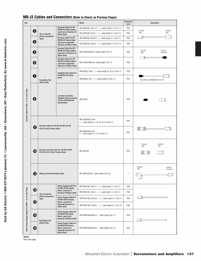
Mitsubishi Electric Automation | Servomotors and Amplifiers 137
Item Model ProtectionLevel Description
Enco
der C
able
for C
N2 –
A-,
B- a
nd T-
Type
10m or Shorter(Direct ConnectionType)
Encoder Cable For HF-MP/HF-KP Series MotorLead Out In Direction OfMotor Shaft
MR-J3ENCBLnnM-A1-H nn = cable length 2, 5, 10m (*1) IP65
MR-J3ENCBLnnM-A1-L nn = cable length 2, 5, 10m (*1) IP65
Encoder Cable For HF-MP/HF-KP Series MotorLead Out In OppositeDirection Of Motor Shaft
MR-J3ENCBLnnM-A2-H nn = cable length 2, 5, 10m (*1) IP65
MR-J3ENCBLnnM-A2-L nn = cable length 2, 5, 10m (*1) IP65
Exceeding 10m(Relay Type)
Encoder Cable For HF-MP/HF-KP Series MotorLead Out In Direction OfMotor Shaft
MR-J3JCBL03M-A1-L Cable length 0.3m (*1) IP20
Encoder Cable For HF-MP/HF-KP Series MotorLead Out In OppositeDirection Of Motor Shaft
MR-J3JCBL03M-A2-L Cable length 0.3m (*1) IP20
Amplifier-Side Cable ForHF-MP/HF-KP SeriesMotor
MR-EKCBLnnM-H nn = cable length 20, 30, 40, 50m (*1) IP20
MR-EKCBLnnM-L nn = cable length 20, 30m (*1) IP20
Junction Connector,Amplifier-Side Connector(*2) For HF-MP/HF-KPSeries Motor
MR-ECNM IP20
9Encoder Cable For HF-SP, HC-RP, HC-UP,HC-LP, HA-LP Series Motor
MR-J3ENSCBLnnM-Hnn = cable length 2, 5, 10, 20, 30, 40, 50m (*1)
IP67
MR-J3ENSCBLnnM-Lnn = cable length 2, 5, 10, 20, 30m (*1)
IP67
10 Encoder Connector Set For HF-SP, HC-RP,HC-UP, HC-LP, HA-LP Series Motor MR-J3SCNS IP67
11 Battery Connection Relay Cable MR-J3BTCBL03M Cable length 0.3m (*3) —
EncoderSide
EncoderSide
JunctionConnector
AmplifierSide
EncoderSide
AmplifierSide
AmplifierSide
JunctionConnector
MR-J3 Cables and Connectors (Refer to Charts on Previous Pages)
Notes:See next page.
Use this in combination of 5 or 6.
Mot
or P
ower
Sup
ply
Cabl
es F
or C
NP3
– A-
,B- a
nd T-
Type 12
10m Or Shorter(Direct ConnectionType
Power Supply Cable ForHF-MP/ HF-KP SeriesMotor. Lead Out InDirection Of Motor Shaft
MR-PWS1CBLnnM-A1-H nn = cable length 2, 5, 10m (*1) IP65
MR-PWS1CBLnnM-A1-L nn = cable length 2, 5, 10m (*1) IP65
13
Power Supply Cable ForHF-MP/ HF-KP SeriesMotor. Lead Out InOpposite Direction ofMotor Shaft
MR-PWS1CBLnnM-A2-H nn = cable length 2, 5, 10m (*1) IP65
MR-PWS1CBLnnM-A2-L nn = cable length 2, 5, 10m (*1) IP65
14
Exceeding 10m(Relay Type)
Power Supply Cable ForHF-MP/HF-KP SeriesMotor Lead Out InDirection Of Motor Shaft
MR-PWS2CBL03M-A1-L Cable length 0.3m (*1) IP55
15
Power Supply Cable ForHF-MP/HF-KP SeriesMotor Lead Out InOpposite Direction OfMotor Shaft
MR-PWS2CBL03M-A2-L Cable length 0.3m (*1) IP55
9
10
11
12
13
14
15
3
4
6
7
8
5
Sold
by
AA
Ele
ctric
1-8
00-2
37-8
274
Lake
land
, FL
• Law
renc
evill
e, G
A •
Gre
ensb
oro,
NC
• Ea
st R
uthe
rfor
d, N
J w
ww
.A-A
elec
tric
.com
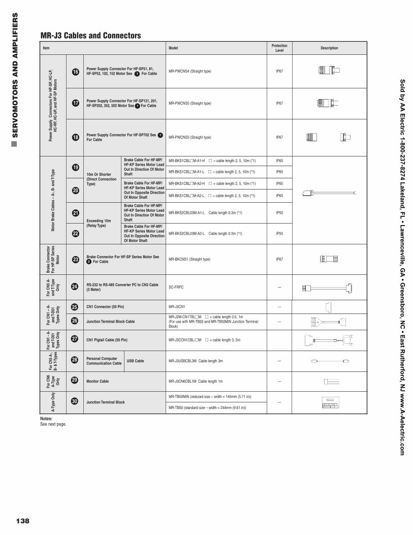
For C
N1 –
A-
and
T-D0
1 Ty
pes
Onl
y CN1 Connector (50 Pin) MR-J3CN1 —
26 Junction Terminal Block CableMR-J2M-CN1TBLnnM nn = cable length 0.5, 1m (For use with MR-TB50 and MR-TB50MIN Junction TerminalBlock)
—
For C
N1 -
A-an
d T-
D01
Type
s O
nly
27 CN1 Pigtail Cable (50 Pin) MR-J3CCN1CBL-nnM nn = cable length 3, 5m
For C
N5 A
-,B-
& T-
Type
s
28 Personal ComputerCommunication Cable USB Cable MR-J3USBCBL3M Cable length 3m —
For C
N6A-
Type
Onl
y
29 Monitor Cable MR-J3CN6CBL1M Cable length 1m —
A-Ty
pe O
nly
30 Junction Terminal BlockMR-TB50MIN (reduced size – width = 145mm (5.71 in))
—MR-TB50 (standard size – width = 244mm (9.61 in))
138
n
SE
RV
OM
OT
OR
S A
ND
AM
PL
IFIE
RS
Item Model ProtectionLevel Description
Pow
er S
uppl
y C
onne
ctor
s Fo
r HF-
SP,H
C-LP
,HC
-RP,
HC-U
P,an
d HF
-SP
Mot
ors
16 Power Supply Connector For HF-SP51, 81,HF-SP52, 102, 152 Motor See A For Cable MR-PWCNS4 (Straight type) IP67
17 Power Supply Connector For HF-SP121, 201,HF-SP202, 352, 502 Motor See 2 For Cable MR-PWCNS5 (Straight type) IP67
18 Power Supply Connector For HF-SP702 See AFor Cable MR-PWCNS3 (Straight type) IP67
Mot
or B
rake
Cab
les
– A-
,B- a
nd T-
Type
19
10m Or Shorter(Direct ConnectionType)
Brake Cable For HF-MP/HF-KP Series Motor LeadOut In Direction Of MotorShaft
MR-BKS1CBLnnM-A1-H nn = cable length 2, 5, 10m (*1) IP65
MR-BKS1CBLnnM-A1-L nn = cable length 2, 5, 10m (*1) IP65
20
Brake Cable For HF-MP/HF-KP Series Motor LeadOut In Opposite DirectionOf Motor Shaft
MR-BKS1CBLnnM-A2-H nn = cable length 2, 5, 10m (*1) IP65
MR-BKS1CBLnnM-A2-L nn = cable length 2, 5, 10m (*1) IP65
21
Exceeding 10m(Relay Type)
Brake Cable For HF-MP/HF-KP Series Motor LeadOut In Direction Of MotorShaft
MR-BKS2CBL03M-A1-L Cable length 0.3m (*1) IP55
22
Brake Cable For HF-MP/HF-KP Series Motor LeadOut In Opposite DirectionOf Motor Shaft
MR-BKS2CBL03M-A2-L Cable length 0.3m (*1) IP55
Brak
e Co
nnec
tor
For H
F-SP
Ser
ies
Mot
or 23 Brake Connector For HF-SP Series Motor SeeB For Cable MR-BKCNS1 (Straight type) IP67
For C
N3 A
-an
d T-
Type
Onl
y
24 RS-232 to RS-485 Converter PC to CN3 Cable (3 Meter) SC-FRPC —
Notes:See next page.
MR-J3 Cables and Connectors
2
1
1
116
17
18
19
20
21
22
23
24
25
26
27
28
29
30
Sold by AA
Electric 1-800-237-8274 Lakeland, FL • Lawrenceville, G
A • G
reensboro, NC
• East Rutherford, N
J ww
w.A
-Aelectric.com
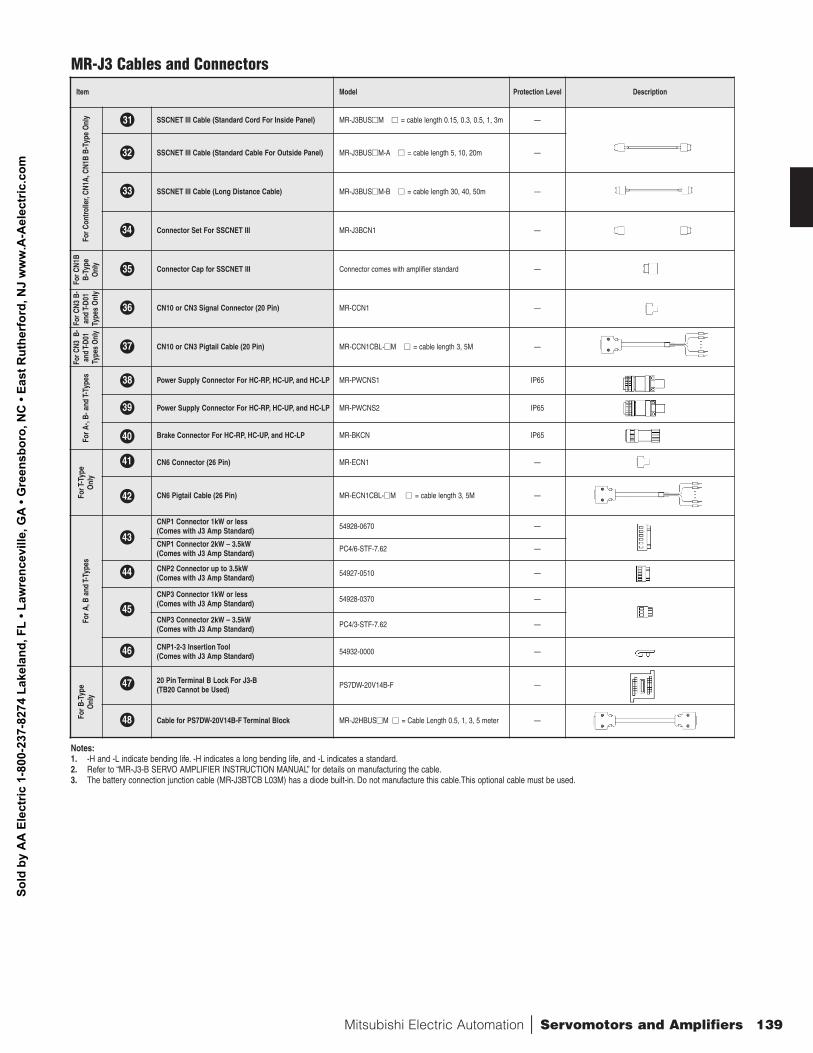
Mitsubishi Electric Automation | Servomotors and Amplifiers 139
Item Model Protection Level DescriptionFo
r Con
trolle
r,CN
1A,C
N1B
B-Ty
pe O
nly 31 SSCNET III Cable (Standard Cord For Inside Panel) MR-J3BUSnnM nn = cable length 0.15, 0.3, 0.5, 1, 3m —
32 SSCNET III Cable (Standard Cable For Outside Panel) MR-J3BUSnnM-A nn = cable length 5, 10, 20m —
33 SSCNET III Cable (Long Distance Cable) MR-J3BUSnnM-B nn = cable length 30, 40, 50m —
34 Connector Set For SSCNET III MR-J3BCN1 —
For C
N1B
B-Ty
peO
nly
35 Connector Cap for SSCNET III Connector comes with amplifier standard —
For C
N3 B
-an
d T-
D01
Type
s O
nly
36 CN10 or CN3 Signal Connector (20 Pin) MR-CCN1 —
For C
N3 B
-an
d T-
D01
Type
s O
nly
37 CN10 or CN3 Pigtail Cable (20 Pin) MR-CCN1CBL-nnM nn = cable length 3, 5M —
For A
-,B-
and
T-Ty
pes
38 Power Supply Connector For HC-RP, HC-UP, and HC-LP MR-PWCNS1 IP65
39 Power Supply Connector For HC-RP, HC-UP, and HC-LP MR-PWCNS2 IP65
40 Brake Connector For HC-RP, HC-UP, and HC-LP MR-BKCN IP65
For T
-Typ
eO
nly
CN6 Connector (26 Pin) MR-ECN1 —
CN6 Pigtail Cable (26 Pin) MR-ECN1CBL-nnM nn = cable length 3, 5M —
For A
,B a
nd T-
Type
s
CNP1 Connector 1kW or less (Comes with J3 Amp Standard) 54928-0670 —
CNP1 Connector 2kW – 3.5kW (Comes with J3 Amp Standard) PC4/6-STF-7.62 —
CNP2 Connector up to 3.5kW(Comes with J3 Amp Standard) 54927-0510 —
CNP3 Connector 1kW or less(Comes with J3 Amp Standard) 54928-0370 —
CNP3 Connector 2kW – 3.5kW (Comes with J3 Amp Standard) PC4/3-STF-7.62 —
CNP1-2-3 Insertion Tool(Comes with J3 Amp Standard) 54932-0000 —
For B
-Typ
eO
nly
20 Pin Terminal B Lock For J3-B (TB20 Cannot be Used) PS7DW-20V14B-F —
Cable for PS7DW-20V14B-F Terminal Block MR-J2HBUSnnM nn = Cable Length 0.5, 1, 3, 5 meter —
MR-J3 Cables and Connectors
31
32
33
34
35
36
37
38
39
40
41
42
43
44
45
46
47
48
Notes:1. -H and -L indicate bending life. -H indicates a long bending life, and -L indicates a standard.2. Refer to “MR-J3-B SERVO AMPLIFIER INSTRUCTION MANUAL” for details on manufacturing the cable.3. The battery connection junction cable (MR-J3BTCB L03M) has a diode built-in. Do not manufacture this cable.This optional cable must be used.
Sold
by
AA
Ele
ctric
1-8
00-2
37-8
274
Lake
land
, FL
• Law
renc
evill
e, G
A •
Gre
ensb
oro,
NC
• Ea
st R
uthe
rfor
d, N
J w
ww
.A-A
elec
tric
.com
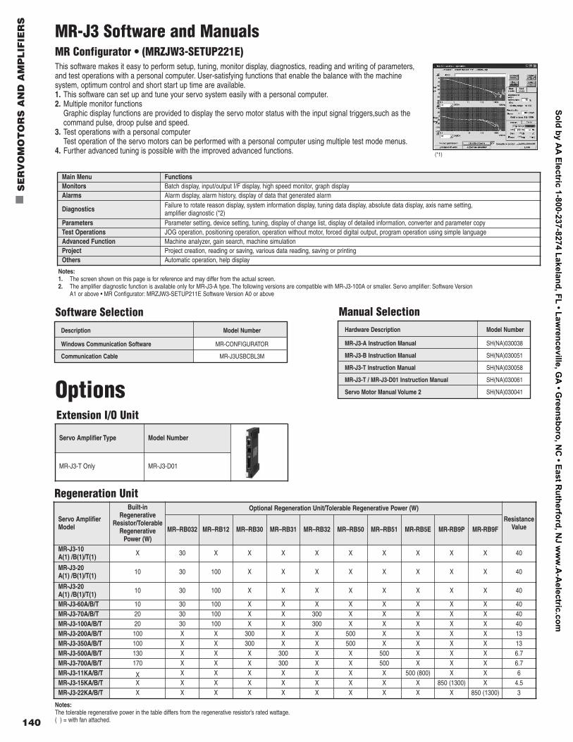
140
n
SE
RV
OM
OT
OR
S A
ND
AM
PL
IFIE
RS
MR-J3 Software and ManualsMR Configurator • (MRZJW3-SETUP221E)This software makes it easy to perform setup, tuning, monitor display, diagnostics, reading and writing of parameters,and test operations with a personal computer. User-satisfying functions that enable the balance with the machinesystem, optimum control and short start up time are available.1. This software can set up and tune your servo system easily with a personal computer.2. Multiple monitor functions
Graphic display functions are provided to display the servo motor status with the input signal triggers,such as thecommand pulse, droop pulse and speed.
3. Test operations with a personal computerTest operation of the servo motors can be performed with a personal computer using multiple test mode menus.
4. Further advanced tuning is possible with the improved advanced functions.
Main Menu FunctionsMonitors Batch display, input/output I/F display, high speed monitor, graph displayAlarms Alarm display, alarm history, display of data that generated alarm
Diagnostics Failure to rotate reason display, system information display, tuning data display, absolute data display, axis name setting,amplifier diagnostic (*2)
Parameters Parameter setting, device setting, tuning, display of change list, display of detailed information, converter and parameter copyTest Operations JOG operation, positioning operation, operation without motor, forced digital output, program operation using simple languageAdvanced Function Machine analyzer, gain search, machine simulationProject Project creation, reading or saving, various data reading, saving or printingOthers Automatic operation, help display
Notes:1. The screen shown on this page is for reference and may differ from the actual screen.2. The amplifier diagnostic function is available only for MR-J3-A type. The following versions are compatible with MR-J3-100A or smaller. Servo amplifier: Software Version
A1 or above • MR Configurator: MRZJW3-SETUP211E Software Version A0 or above
Description Model Number
Windows Communication Software MR-CONFIGURATOR
Communication Cable MR-J3USBCBL3M
Software Selection
Extension I/O Unit
Hardware Description Model Number
MR-J3-A Instruction Manual SH(NA)030038
MR-J3-B Instruction Manual SH(NA)030051
MR-J3-T Instruction Manual SH(NA)030058
MR-J3-T / MR-J3-D01 Instruction Manual SH(NA)030061
Servo Motor Manual Volume 2 SH(NA)030041
Manual Selection
Options
Regeneration Unit
Servo AmplifierModel
Built-inRegenerative
Resistor/TolerableRegenerative
Power (W)
Optional Regeneration Unit/Tolerable Regenerative Power (W)
ResistanceValueMR–RB032 MR–RB12 MR–RB30 MR–RB31 MR–RB32 MR–RB50 MR–RB51 MR-RB5E MR-RB9P MR-RB9F
MR-J3-10A(1) /B(1)/T(1) X 30 X X X X X X X X X 40
MR-J3-20A(1) /B(1)/T(1) 10 30 100 X X X X X X X X 40
MR-J3-20A(1) /B(1)/T(1) 10 30 100 X X X X X X X X 40
MR-J3-60A/B/T 10 30 100 X X X X X X X X 40MR-J3-70A/B/T 20 30 100 X X 300 X X X X X 40MR-J3-100A/B/T 20 30 100 X X 300 X X X X X 40MR-J3-200A/B/T 100 X X 300 X X 500 X X X X 13MR-J3-350A/B/T 100 X X 300 X X 500 X X X X 13MR-J3-500A/B/T 130 X X X 300 X X 500 X X X 6.7MR-J3-700A/B/T 170 X X X 300 X X 500 X X X 6.7MR-J3-11KA/B/T X X X X X X X X 500 (800) X X 6MR-J3-15KA/B/T X X X X X X X X X 850 (1300) X 4.5MR-J3-22KA/B/T X X X X X X X X X X 850 (1300) 3
Notes:The tolerable regenerative power in the table differs from the regenerative resistor’s rated wattage.( ) = with fan attached.
Servo Amplifier Type Model Number
MR-J3-T Only MR-J3-D01
(*1)
Sold by AA
Electric 1-800-237-8274 Lakeland, FL • Lawrenceville, G
A • G
reensboro, NC
• East Rutherford, N
J ww
w.A
-Aelectric.com
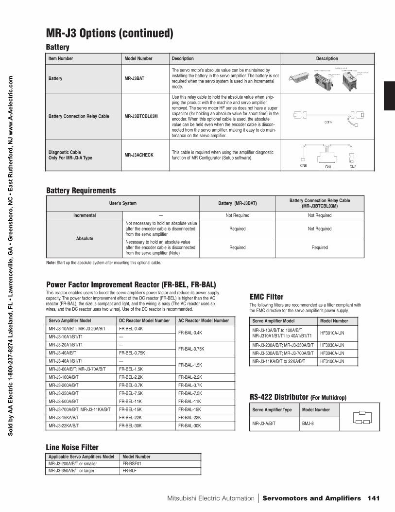
Mitsubishi Electric Automation | Servomotors and Amplifiers 141
Item Number Model Number Description Description
Battery MR-J3BAT
The servo motor’s absolute value can be maintained byinstalling the battery in the servo amplifier. The battery is notrequired when the servo system is used in an incrementalmode.
Battery Connection Relay Cable MR-J3BTCBL03M
Use this relay cable to hold the absolute value when ship-ping the product with the machine and servo amplifierremoved. The servo motor HF series does not have a supercapacitor (for holding an absolute value for short time) in theencoder. When this optional cable is used, the absolutevalue can be held even when the encoder cable is discon-nected from the servo amplifier, making it easy to do main-tenance on the servo amplifier.
Diagnostic CableOnly For MR-J3-A Type MR-J3ACHECK This cable is required when using the amplifier diagnostic
function of MR Configurator (Setup software).
CN6 CN2CN1
MR-J3 Options (continued)Battery
User’s System Battery (MR-J3BAT) Battery Connection Relay Cable(MR-J3BTCBL03M)
Incremental — Not Required Not Required
Absolute
Not necessary to hold an absolute valueafter the encoder cable is disconnectedfrom the servo amplifier
Required Not Required
Necessary to hold an absolute valueafter the encoder cable is disconnectedfrom the servo amplifier (Note)
Required Required
Note: Start up the absolute system after mounting this optional cable.
Battery Requirements
Power Factor Improvement Reactor (FR-BEL, FR-BAL)This reactor enables users to boost the servo amplifier’s power factor and reduce its power supplycapacity. The power factor improvement effect of the DC reactor (FR-BEL) is higher than the ACreactor (FR-BAL), the size is compact and light, and the wiring is easy (The AC reactor uses sixwires, and the DC reactor uses two wires). Use of the DC reactor is recommended.
Servo Amplifier Model DC Reactor Model Number AC Reactor Model Number
MR-J3-10A/B/T; MR-J3-20A/B/T FR-BEL-0.4KFR-BAL-0.4K
MR-J3-10A1/B1/T1 —
MR-J3-20A1/B1/T1 —FR-BAL-0.75K
MR-J3-40A/B/T FR-BEL-0.75K
MR-J3-40A1/B1/T1 —FR-BAL-1.5K
MR-J3-60A/B/T; MR-J3-70A/B/T FR-BEL-1.5K
MR-J3-100A/B/T FR-BEL-2.2K FR-BAL-2.2K
MR-J3-200A/B/T FR-BEL-3.7K FR-BAL-3.7K
MR-J3-350A/B/T FR-BEL-7.5K FR-BAL-7.5K
MR-J3-500A/B/T FR-BEL-11K FR-BAL-11K
MR-J3-700A/B/T; MR-J3-11KA/B/T FR-BEL-15K FR-BAL-15K
MR-J3-15KA/B/T FR-BEL-22K FR-BAL-22K
MR-J3-22KA/B/T FR-BEL-30K FR-BAL-30K
EMC FilterThe following filters are recommended as a filter compliant withthe EMC directive for the servo amplifier’s power supply.
Servo Amplifier Model Model Number
MR-J3-10A/B/T to 100A/B/TMR-J310A1/B1/T1 to 40A1/B1/T1 HF3010A-UN
MR-J3-200A/B/T; MR-J3-350A/B/T HF3030A-UN
MR-J3-500A/B/T; MR-J3-700A/B/T HF3040A-UN
MR-J3-11KA/B/T to 22KA/B/T HF3100A-UN
RS-422 Distributor (For Multidrop)
Servo Amplifier Type Model Number
MR-J3-A/B/T BMJ-8
Applicable Servo Amplifiers Model Model NumberMR-J3-200A/B/T or smaller FR-BSF01MR-J3-350A/B/T or larger FR-BLF
Line Noise Filter
Sold
by
AA
Ele
ctric
1-8
00-2
37-8
274
Lake
land
, FL
• Law
renc
evill
e, G
A •
Gre
ensb
oro,
NC
• Ea
st R
uthe
rfor
d, N
J w
ww
.A-A
elec
tric
.com
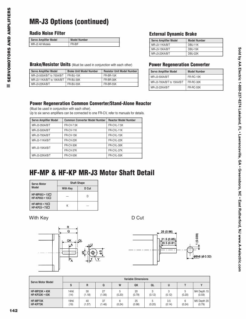
HF-MP & HF-KP MR-J3 Motor Shaft DetailServo MotorModel
Shaft Shape
With Key D Cut
HF-MP053 • 13oo
HF-KP053 • 13oo
— D
HF-MP23 • 73oo
HF-KP23 • 73oo
K —
Servo Motor ModelVariable Dimensions
S R Q W QK QL U T Y
HF-MP23K • 43KHF-KP23K • 43K
14h6 (14)
30(1.18)
27(1.06)
5(0.20)
20(0.79)
3(0.12)
3(0.12)
5(0.20)
M4 Depth 15(0.59)
HF-MP73KHF-KP73K
19h6(19)
40(1.57)
37(1.46)
6(0.24)
25(0.98)
5(0.20)
3.5(0.14)
6(0.24)
M5 Depth 20(0.79)
D CutWith Key
142
n
SE
RV
OM
OT
OR
S A
ND
AM
PL
IFIE
RS
Servo Amplifier Model Model NumberMR-J3 All Models FR-BIF
Radio Noise Filter
MR-J3 Options (continued)
External Dynamic Brake
Brake/Resistor Units (Must be used in conjunction with each other) Power Regeneration Converter
Power Regeneration Common Converter/Stand-Alone Reactor(Must be used in conjunction with each other).Up to six servo amplifiers can be connected to one FR-CV, refer to manuals for details.
Servo Amplifier Model Model NumberMR-J3-11KA/B/T DBU-11K
MR-J3-15KA/B/T DBU-15K
MR-J3-22KA/B/T DBU-22K
Servo Amplifier Model Brake Unit Model Number Resistor Unit Model NumberMR-J3-500A/B/T to 700A/B/T FR-BU-15K FR-BR-15KMR-J3-11KA/B/T to 15KA/B/T FR-BU-30K FR-BR-30KMR-J3-22KA/B/T FR-BU-55K FR-BR-55K
Servo Amplifier Model Model Number
MR-J3-500A/B/T FR-RC-15K
MR-J3-700A/B/T to 15KA/B/T FR-RC-30K
MR-J3-22KA/B/T FR-RC-55K
Servo Amplifier Model Common Converter Model Number Reactor Model Number
MR-J3-350A/B/T FR-CV-7.5K FR-CVL-7.5K
MR-J3-500A/B/T FR-CV-11K FR-CVL-11K
MR-J3-700A/B/T FR-CV-15K FR-CVL-15K
MR-J3-11KA/B/T FR-CV-22K FR-CVL-22K
MR-J3-15KA/B/T FR-CV-30K FR-CVL-30K
FR-CV-37K FR-CVL-37K
MR-J3-22KA/B/T FR-CV-55K FR-CVL-55K
Sold by AA
Electric 1-800-237-8274 Lakeland, FL • Lawrenceville, G
A • G
reensboro, NC
• East Rutherford, N
J ww
w.A
-Aelectric.com
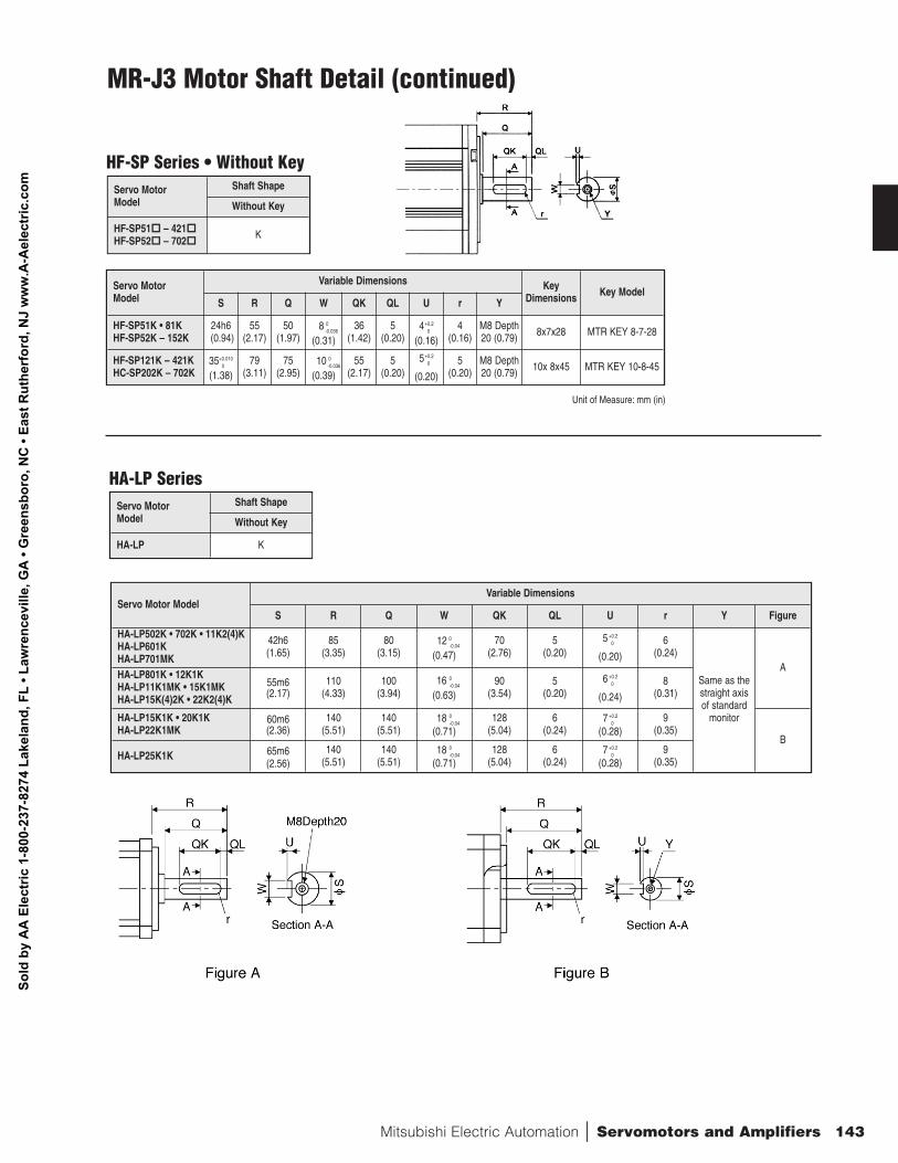
Mitsubishi Electric Automation | Servomotors and Amplifiers 143
HF-SP Series • Without KeyServo MotorModel
Shaft Shape
Without Key
HF-SP51oo
– 421oo
HF-SP52oo
– 702oo
K
Servo Motor Model
Variable Dimensions KeyDimensions Key Model
S R Q W QK QL U r Y
HF-SP51K • 81KHF-SP52K – 152K
24h6(0.94)
55(2.17)
50(1.97)
8 0-0.036
(0.31)36
(1.42)5
(0.20)4+0.2
0
(0.16)4
(0.16)M8 Depth20 (0.79) 8x7x28 MTR KEY 8-7-28
HF-SP121K – 421KHC-SP202K – 702K
35+0.0100
(1.38)79
(3.11)75
(2.95)10 0
-0.036
(0.39)55
(2.17)5
(0.20)5+0.2
0
(0.20)
5(0.20)
M8 Depth20 (0.79) 10x 8x45 MTR KEY 10-8-45
Unit of Measure: mm (in)
MR-J3 Motor Shaft Detail (continued)
HA-LP SeriesServo MotorModel
Shaft Shape
Without Key
HA-LP K
Servo Motor ModelVariable Dimensions
S R Q W QK QL U r Y Figure
HA-LP502K • 702K • 11K2(4)KHA-LP601KHA-LP701MK
42h6(1.65)
85(3.35)
80(3.15)
12 0-0.04
(0.47)70
(2.76)5
(0.20)5 +0.2
0
(0.20)
6(0.24)
Same as thestraight axis of standard
monitor
AHA-LP801K • 12K1KHA-LP11K1MK • 15K1MKHA-LP15K(4)2K • 22K2(4)K
55m6(2.17)
110(4.33)
100(3.94)
16 0-0.04
(0.63)90
(3.54)5
(0.20)6 +0.2
0
(0.24)
8(0.31)
HA-LP15K1K • 20K1KHA-LP22K1MK
60m6(2.36)
140(5.51)
140(5.51)
18 0-0.04
(0.71)128
(5.04)6
(0.24)7 +0.2
0
(0.28)9
(0.35)B
HA-LP25K1K 65m6(2.56)
140(5.51)
140(5.51)
18 0-0.04
(0.71)128
(5.04)6
(0.24)7 +0.2
0
(0.28)9
(0.35)
Sold
by
AA
Ele
ctric
1-8
00-2
37-8
274
Lake
land
, FL
• Law
renc
evill
e, G
A •
Gre
ensb
oro,
NC
• Ea
st R
uthe
rfor
d, N
J w
ww
.A-A
elec
tric
.com
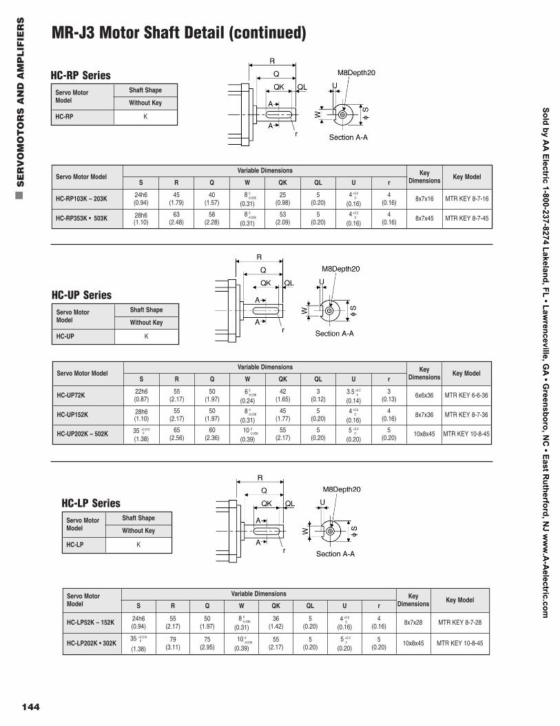
HC-LP SeriesServo MotorModel
Shaft Shape
Without Key
HC-LP K
Servo Motor Model
Variable Dimensions KeyDimensions Key Model
S R Q W QK QL U r
HC-LP52K – 152K 24h6 (0.94)
55(2.17)
50(1.97)
8 0-0.036
(0.31)36
(1.42)5
(0.20)4 +0.2
0
(0.16)4
(0.16) 8x7x28 MTR KEY 8-7-28
HC-LP202K • 302K35 +0.010
0
(1.38)79
(3.11)75
(2.95)10 0
-0.036
(0.39)55
(2.17)5
(0.20)5 +0.2
0
(0.20)5
(0.20) 10x8x45 MTR KEY 10-8-45
HC-UP SeriesServo MotorModel
Shaft Shape
Without Key
HC-UP K
Servo Motor ModelVariable Dimensions Key
Dimensions Key ModelS R Q W QK QL U r
HC-UP72K 22h6(0.87)
55(2.17)
50(1.97)
6 0-0.036
(0.24)42
(1.65)3
(0.12)3.5 +0.2
0
(0.14)3
(0.13) 6x6x36 MTR KEY 6-6-36
HC-UP152K 28h6(1.10)
55(2.17)
50(1.97)
8 0-0.036
(0.31)45
(1.77)5
(0.20)4 +0.2
0
(0.16)4
(0.16) 8x7x36 MTR KEY 8-7-36
HC-UP202K – 502K 35 +0.0100
(1.38)65
(2.56)60
(2.36)10 0
-0.036
(0.39)55
(2.17)5
(0.20)5 +0.2
0
(0.20)5
(0.20) 10x8x45 MTR KEY 10-8-45
144
n
SE
RV
OM
OT
OR
S A
ND
AM
PL
IFIE
RS
HC-RP SeriesServo MotorModel
Shaft Shape
Without Key
HC-RP K
Servo Motor ModelVariable Dimensions Key
Dimensions Key ModelS R Q W QK QL U r
HC-RP103K – 203K 24h6 (0.94)
45(1.79)
40(1.57)
8 0-0.036
(0.31)25
(0.98)5
(0.20)4 +0.2
0
(0.16)4
(0.16) 8x7x16 MTR KEY 8-7-16
HC-RP353K • 503K 28h6(1.10)
63(2.48)
58(2.28)
8 0-0.036
(0.31)53
(2.09)5
(0.20)4 +0.2
0
(0.16)4
(0.16) 8x7x45 MTR KEY 8-7-45
MR-J3 Motor Shaft Detail (continued)
Sold by AA
Electric 1-800-237-8274 Lakeland, FL • Lawrenceville, G
A • G
reensboro, NC
• East Rutherford, N
J ww
w.A
-Aelectric.com
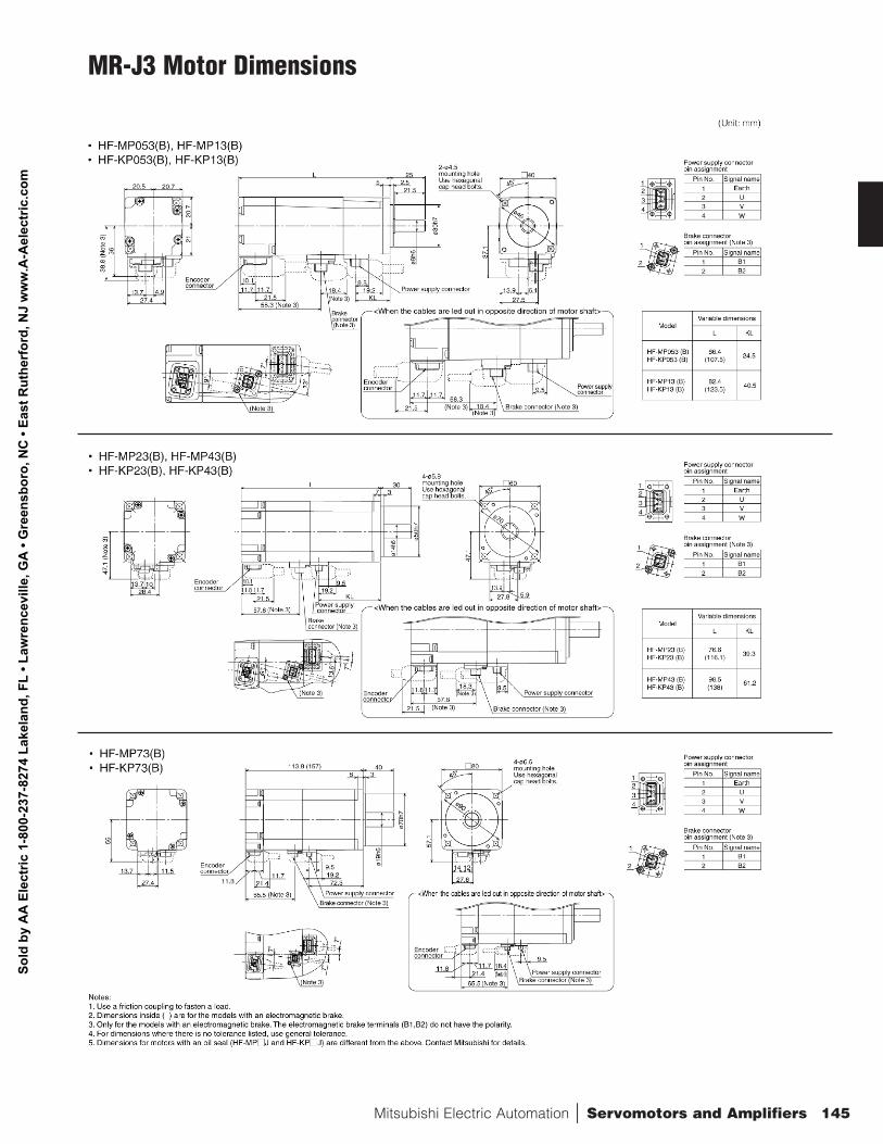
Mitsubishi Electric Automation | Servomotors and Amplifiers 145
MR-J3 Motor Dimensions
Sold
by
AA
Ele
ctric
1-8
00-2
37-8
274
Lake
land
, FL
• Law
renc
evill
e, G
A •
Gre
ensb
oro,
NC
• Ea
st R
uthe
rfor
d, N
J w
ww
.A-A
elec
tric
.com
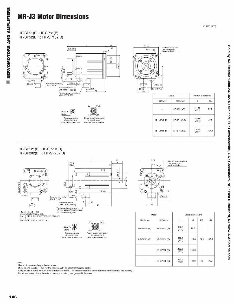
146
n
SE
RV
OM
OT
OR
S A
ND
AM
PL
IFIE
RS
MR-J3 Motor Dimensions
Sold by AA
Electric 1-800-237-8274 Lakeland, FL • Lawrenceville, G
A • G
reensboro, NC
• East Rutherford, N
J ww
w.A
-Aelectric.com
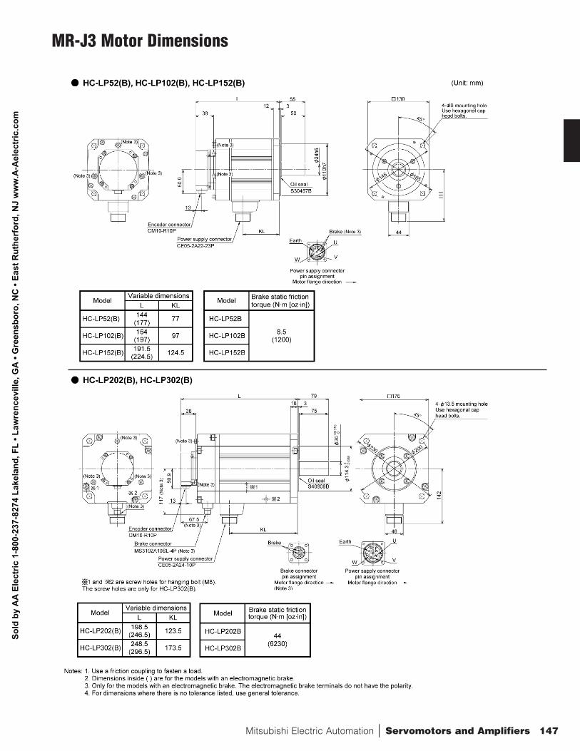
Mitsubishi Electric Automation | Servomotors and Amplifiers 147
MR-J3 Motor Dimensions
Sold
by
AA
Ele
ctric
1-8
00-2
37-8
274
Lake
land
, FL
• Law
renc
evill
e, G
A •
Gre
ensb
oro,
NC
• Ea
st R
uthe
rfor
d, N
J w
ww
.A-A
elec
tric
.com
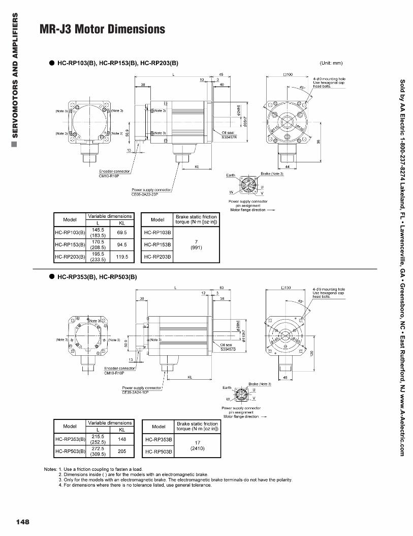
148
n
SE
RV
OM
OT
OR
S A
ND
AM
PL
IFIE
RS
MR-J3 Motor Dimensions
Sold by AA
Electric 1-800-237-8274 Lakeland, FL • Lawrenceville, G
A • G
reensboro, NC
• East Rutherford, N
J ww
w.A
-Aelectric.com
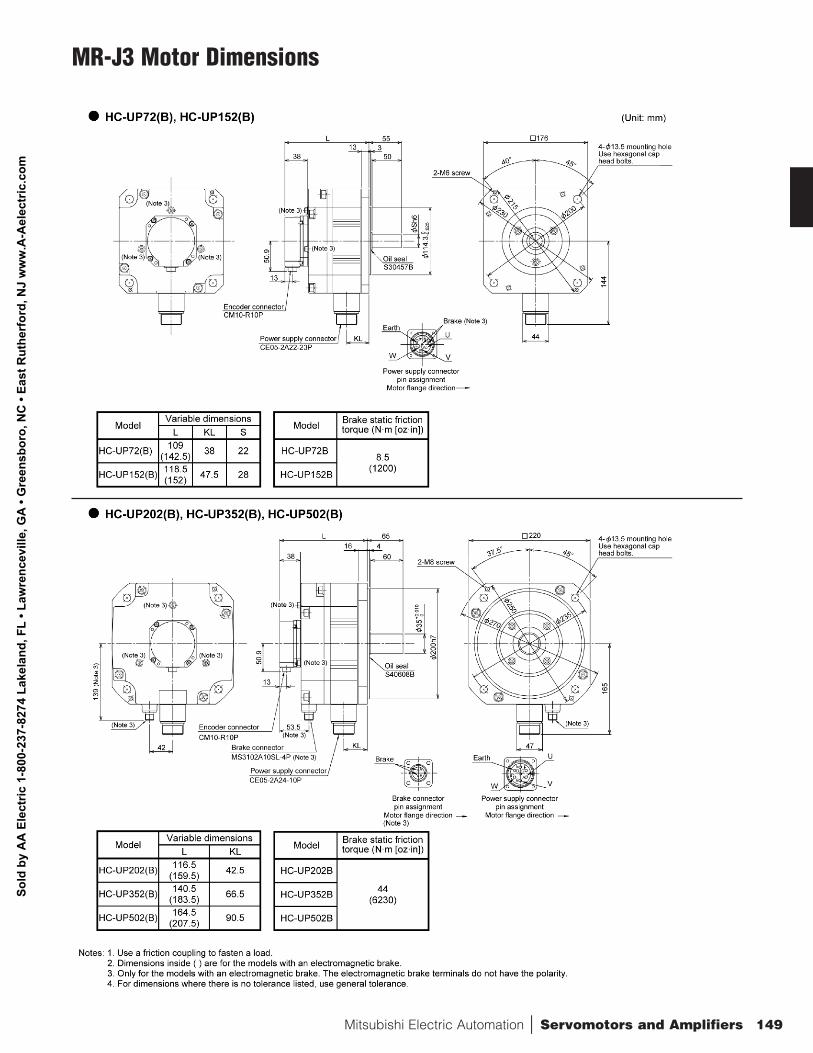
Mitsubishi Electric Automation | Servomotors and Amplifiers 149
MR-J3 Motor Dimensions
Sold
by
AA
Ele
ctric
1-8
00-2
37-8
274
Lake
land
, FL
• Law
renc
evill
e, G
A •
Gre
ensb
oro,
NC
• Ea
st R
uthe
rfor
d, N
J w
ww
.A-A
elec
tric
.com
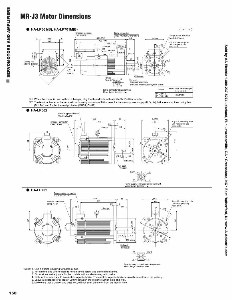
150
n
SE
RV
OM
OT
OR
S A
ND
AM
PL
IFIE
RS
MR-J3 Motor Dimensions
Sold by AA
Electric 1-800-237-8274 Lakeland, FL • Lawrenceville, G
A • G
reensboro, NC
• East Rutherford, N
J ww
w.A
-Aelectric.com
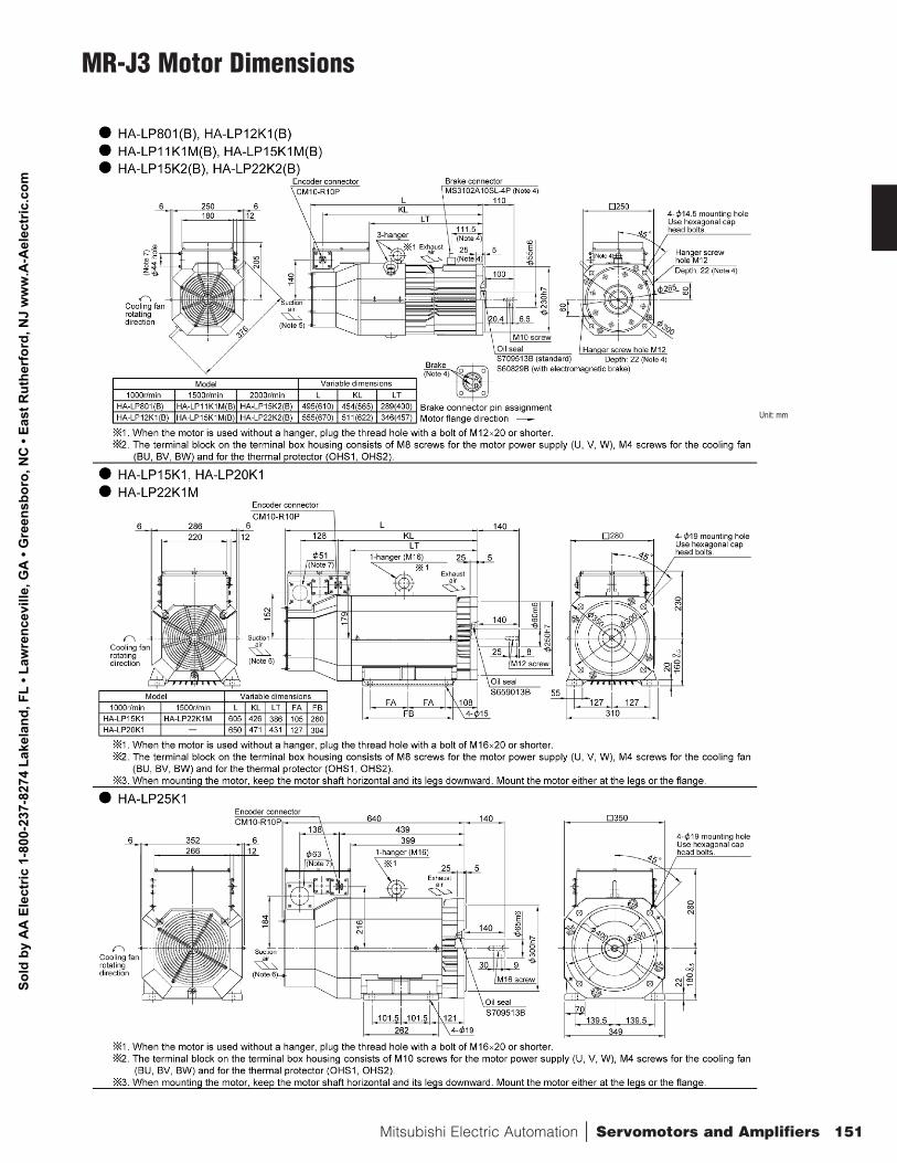
Mitsubishi Electric Automation | Servomotors and Amplifiers 151
MR-J3 Motor Dimensions
Unit: mm
Sold
by
AA
Ele
ctric
1-8
00-2
37-8
274
Lake
land
, FL
• Law
renc
evill
e, G
A •
Gre
ensb
oro,
NC
• Ea
st R
uthe
rfor
d, N
J w
ww
.A-A
elec
tric
.com
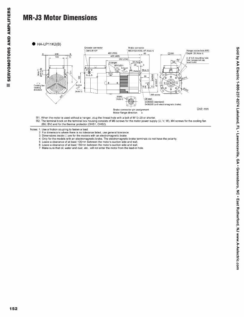
152
n
SE
RV
OM
OT
OR
S A
ND
AM
PL
IFIE
RS
MR-J3 Motor Dimensions
Unit: mm
Sold by AA
Electric 1-800-237-8274 Lakeland, FL • Lawrenceville, G
A • G
reensboro, NC
• East Rutherford, N
J ww
w.A
-Aelectric.com