mpc2810 hardware manual 20100730 cje-andy .doc
TRANSCRIPT

MPC2810
Hardware Manual
Rev. 1.0
December, 2008

MPC2810 Motion Controller Hardware Manual
II
The content of this manual has been carefully prepared and is believed
to be accurate. However, no responsibility is assumed for
misunderstanding and inaccuracies.
Leetro Automation Co., Ltd. reserves the right to make changes
without further notice to any products herein to improve reliability,
function or design. Leetro Automation Co., Ltd. does not assume any
liability arising out of the application or use of any products or
circuitry described herein; neither does it convey any license under its
patent rights of others. Both Step-Servo™ and Leetro™ are trademark
of Leetro Automation Co., Ltd.
Leetro’s general policy does not recommend the use of its products in
life support or aircraft applications wherein a failure or malfunction of
the product may directly threaten life or injury. Per Leetro’s terms and
conditions of sales, the user of Leetro Automation Co., Ltd. products
in life support or aircraft applications assumes all risks of such use and
indemnifies Leetro Automation Co., Ltd. against all damages.
Contact
Leetro Automation Co., Ltd.
Building 8-B
Dayi Zone of Incubating Hi-tech
No.1 South 2nd Keyuan Road
Chengdu 610041
CHINA
Internet: http://www.leetro.com
Email: [email protected]
Tel: +86 28 85142599
FAX: +86 28 85187774
©2010 by Leetro Automation Co., Ltd. All Rights Reserved

MPC2810 Motion Controller Hardware Manual
III
PrefaceThank you for buying and using Leetro Automation’s Leetro™ motion
controllers.
MPC2810 is a high-performance universal motion controller developed by
Leetro Automation Co., Ltd. Please read through this manual for
specifications and proper use, especially the “Safety Precautions”section.
Your motion controller has been designed to work with both servo and
stepper motors. Installation and system setup will vary depending on whether
the controller will be used with stepper motors or servo motors.

MPC2810 Motion Controller Hardware Manual
IV
Safety Warnings
Please pay attention to following warnings to avoid any injury or machine
damage.
In this document, the following symbols are used to indicate the
level of damages. Ignoring the warnings might cause injuries.
The following symbols represent "MUST NOT" or "MUST"
operations which you have to observe.
Routine Safety Precautions
Please read through the routine safety precautions to avoid any injury or
property damage.
Use only quality power cables.
Make a connection or disconnection correctly and securely. The power
shouldn’t be turned on till the wire connection completes. The control
Indicates a potentially hazardous situation, if not
avoided, will result in death or serious injury.Danger
Indicates a potentially hazardous situation, if not
avoided, will result in minor injury or property damage.
Represents "MUST NOT" operation, which is
inhibited.
Represents "MUST" operation, which has to be
executed.
Caution

MPC2810 Motion Controller Hardware Manual
V
card should be connected to the Breakout board first, then the motors and
drives to the Breakout board. To disconnect the system correctly and
securely, make sure to turn off the external power supply first.
Disconnect the motors and motor drives from the Breakout board, and
then disconnect the control cards from the Breakout board.
Do not operate if there are suspicions of potential errors. If you suspect
any parts of the Product are damaged, please have them inspected by
qualified technicians.
Do not subject the Product to water, corrosive or flammable gases, and
combustibles.
Keep the Product from dust and humidity.
Prevent the Product from ESD damage. Do not touch the electronic
components on the control cards. Do not place the control cards on
surfaces possible to have ESD impacts on the Product. Place the control
cards in ESD-proof bags or packages.

MPC2810 Motion Controller Hardware Manual
VI
Warranty Information
This is to certify that MPC2810 controllers are guaranteed by Leetro
Automation Co., Ltd. to be free of all defects in material and workmanship
for a period of 12 months from the date of delivery. The warranty does not
apply to any defect caused by negligence, misuse (including environmental
factors), accident, alteration, or improper maintenance.
If, within one year from the date of delivery, any part of the Product should
fail to operate, contact the company Customer Service department in the
region and report the problem. When calling for support, please be prepare to
provide the dates of purchase and delivery, model number and serial number
of the unit, and a brief description of the problem.
Leetro Automation Co. Ltd neither assumes nor authorized any
representative or other person to assume for us any other warranties in
connection with the sale, service, or shipment of our products. Leetro
Automation Co. Ltd. reserve the right to make changes and improvements in
the design of our products at any time without incurring any obligation to
make equivalent changes in products previously manufactured or shipped.
Warranty Period
Leetro Automation Co., Ltd. warrants its motion control cards against defects
in materials and workmanship for a period of 12 months from the date of
delivery. During the warranty period, Leetro Automation will either, at its
option, repair or replace products which prove to be defective.

MPC2810 Motion Controller Hardware Manual
VII
Warranty Range
If the Product failed or has been damaged due to company’s
manufacturing and is within the warranty period, we will repair or replace it.
Following cases are exclusive from the warranty:
Failure and damage caused by improper operation or improper
operating environment.
Failure and damage caused by the devices or the control software
produced by other than our company.
Repair and modification by other than our company.
Failure and damage caused by natural disasters.
Customers are responsible for the shipping costs.
Product Application Precaution
The Product is designed for general industrial applications. Leetro does not
recommend the use of its products in life support or aircraft applications
wherein a failure or malfunction of the product may directly threaten life or
injury.
Maintenance
Routine maintenance and inspection of the motion controller are essential for
the proper and safe operation.

MPC2810 Motion Controller Hardware Manual
VIII
TABLE OF CONTENTS
1 OVERVIEW....................................................................... 11.1 INTRODUCTION ............................................................................................11.2 THE MANUAL IS FOR ....................................................................................21.3 FEATURES ....................................................................................................21.4 SPECIFICATIONS ...........................................................................................41.5 TYPICAL CONTROL SYSTEM.........................................................................5
2 Quick Installation............................................................... 62.1 CHECK YOUR PACKAGE...............................................................................62.2 MPC2810/P62-01/P37-05/P62-02 LAYOUT ................................................62.3 HARDWARE INSTALLATION ........................................................................102.4 SOFTWARE INSTALLATION .........................................................................102.5 UNINSTALL SOFTWARE...............................................................................202.6 SOFTWARE UPDATE....................................................................................20
3 How to Use ...................................................................... 213.1 PARAMETER SETUP ....................................................................................213.2 SIGNAL INTERFACE ....................................................................................22
3.2.1 Breakout board-P62-01 ......................................................................223.2.2 Universal I/O Extension Cable-C4037...............................................243.2.3 Breakout board-P62-02 ......................................................................26
3.3 CONNECTION .............................................................................................293.3.1 Connect MPC2810 to P62-01 ............................................................293.3.2 Connect P2810 to Power Supply........................................................303.3.3 Connect P62-01 to Motor Drive.........................................................30
3.3.3.1 OUTPUTS...................................................................................303.3.3.2 CONNECT ENCODER INPUTS ...............................................323.3.3.3 CONNECT DEDICATED INPUTS............................................333.3.3.4 CONNECTING UNIVERSAL I/O .............................................33
4 System Debugging........................................................... 364.1 DESTINATION PATH ....................................................................................364.2 HOW TO USE THE DEBUGGING PROGRAM ...................................................37
5 Typical Connection .......................................................... 425.1 CONNECT MPC2810 TO DMD808 STEPPER MOTOR DRIVE ......................425.2 CONNECT MPC2810 TO PANASONIC MINAS A SERIES SERVO MOTOR
DRIVE ..............................................................................................................43

MPC2810 Motion Controller Hardware Manual
1
1 OVERVIEW
1.1 Introduction
Leetro™ MPC2810 is a high-performance 1 to 4-axis PCI-BUS card for stepper
motors and digital servo motors. Multiple MPC2810 control cards can be put in a
PC to control up to 16 axes.
MPC2810 motion control card adopts IBM-PC and its compatible PC as the host
computer. It is a PC-based control unit for stepper motor and digital servo motor.
With the advanced Field Programmable Gate Array (FPGA), MPC2810 provides
dedicated motion control features such as pulse/direction or CW/CCW signal
output, forward/reverse limit and origin input for each axis,
acceleration-deceleration control, linear and circle interpolations, and much more.
For step motors/servo motors, pulse output rate up to 2.0 MHz provides fast and
smooth motion for full step or micro-stepping drivers.
Based on MPC2810’s powerful functions and Windows DLL, the user can
develop various motion control system easily. Library, header files and module
declare files are applicable for current popular programming development tools
such as Visual Basic6.0 and Visual C++6.0. MPC2810’s functions are also
conveniently applicable for other 32-bit Windows development tools such as
Delphi, C++ Builder, and etc. Moreover, the configuration software that supports
Windows DLL can also use MPC2810 motion controller.
MPC2810 Motion Controller Hardware Manual
2
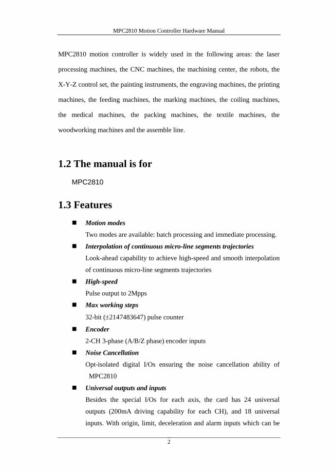
MPC2810 motion controller is widely used in the following areas: the laser
processing machines, the CNC machines, the machining center, the robots, the
X-Y-Z control set, the painting instruments, the engraving machines, the printing
machines, the feeding machines, the marking machines, the coiling machines,
the medical machines, the packing machines, the textile machines, the
woodworking machines and the assemble line.
1.2 The manual is for
MPC2810
1.3 Features
Motion modes
Two modes are available: batch processing and immediate processing.
Interpolation of continuous micro-line segments trajectories
Look-ahead capability to achieve high-speed and smooth interpolation
of continuous micro-line segments trajectories
High-speed
Pulse output to 2Mpps
Max working steps
32-bit (2147483647) pulse counter
Encoder
2-CH 3-phase (A/B/Z phase) encoder inputs
Noise Cancellation
Opt-isolated digital I/Os ensuring the noise cancellation ability of
MPC2810
Universal outputs and inputs
Besides the special I/Os for each axis, the card has 24 universal
outputs (200mA driving capability for each CH), and 18 universal
inputs. With origin, limit, deceleration and alarm inputs which can be

MPC2810 Motion Controller Hardware Manual
3
set as universal inputs inclusive, there can be up to 35-CH universal
inputs.
Interpolations
2 to 4-axes linear interpolation and 2-axes circular interpolation
Event processing
Internal events can be triggered automatically once the motion control
card receives signals such as forward limit, reverse limit, origin, Z
pulse, stop, alarm, etc. User can easily write event processing program.
Comparative position control output
Interface commands are used for setting the universal outputs 1-4 as
comparative position control outputs.
Encoder latch
MPC2810 motion controller can latch encoder feedback signals of
1-Ch and 2-Ch.
Destination Position Verify
Automatic destination error compensation
Set acceleration-deceleration
User can easily set acceleration-deceleration process if the default
T/S-curve modes can not satisfy user’s requirements.
Input interface for manual pulse generator
Electronic gearing
Watchdog timer
Software limits
Tracking error limit
When axis1 or axis2 following error overruns the set maximum limit,
MPC2810 automatically stops corresponding axis’s motion when user
enable the function.
MPC2810 Motion Controller Hardware Manual
4
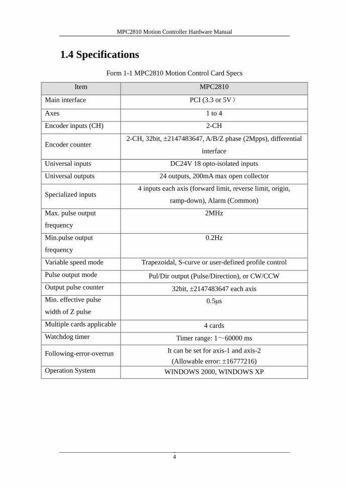
1.4 Specifications
Form 1-1 MPC2810 Motion Control Card Specs
Item MPC2810
Main interface PCI (3.3 or 5V)
Axes 1 to 4
Encoder inputs (CH) 2-CH
Encoder counter2-CH, 32bit, 2147483647, A/B/Z phase (2Mpps), differential
interface
Universal inputs DC24V 18 opto-isolated inputs
Universal outputs 24 outputs, 200mA max open collector
Specialized inputs4 inputs each axis (forward limit, reverse limit, origin,
ramp-down), Alarm (Common)
Max. pulse output
frequency
2MHz
Min.pulse output
frequency
0.2Hz
Variable speed mode Trapezoidal, S-curve or user-defined profile control
Pulse output mode Pul/Dir output (Pulse/Direction), or CW/CCW
Output pulse counter 32bit, 2147483647 each axis
Min. effective pulse
width of Z pulse
0.5μs
Multiple cards applicable 4 cards
Watchdog timer Timer range: 1~60000 ms
Following-error-overrun It can be set for axis-1 and axis-2
(Allowable error: 16777216)
Operation System WINDOWS 2000, WINDOWS XP

MPC2810 Motion Controller Hardware Manual
5
1.5 Typical Control System
A typical motion control system that uses MPC2810 as motion control card is
comprised of:
1) MPC2810 motion control card and breakout board;
2) PC or industrial control computer with PCI slot, Windows2000/XP
operation system;
3) Stepper motor or digital servo motor;
4) Motor drives;
5) Power supplies for motor drives;
6) DC switch power supply, providing +24V power to the breakout
board.
Fig.1-1 Control System using MPC2810
Worktable
Motion Control Card
Breakout Board
Motor Drive
Motor
PC

MPC2810 Motion Controller Hardware Manual
6
2 Quick Installation
2.1 Check Your Package
Standard package list:
1* MPC2810 motion control card;
1* P62-01 breakout board or 1* P62-02 breakout board;
1* 62-pin shielded cable, 2m;
1* Software toolkit.
Following optional accessories are used for providing more universal I/O
ports if required:
1* C4037 universal I/O extension cable;
1*P37-05 breakout board (matching P62-01 breakout board);
1*37-pin shielded cable, 2m.
2.2 MPC2810/P62-01/P37-05/P62-02 Layout
There are two types of breakout board: P62-01 and P62-02. Only special
input/output signals, such pulse, direction, limits, origin, ramp-down etc., and a
few universal I/O connectors are on the P62-01 board. All motion control card
signals connectors are on the P62-02.
(1) MPC2810 motion control card
4 indicator lights on the back of the board
J1: connect interface for 62-pin shielded cable
J2: connect interface for 40-pin flat cable of universal IO extension cable
Switch: used for setting the local ID of cards if multiple cards are applied.
MPC2810 Motion Controller Hardware Manual
7
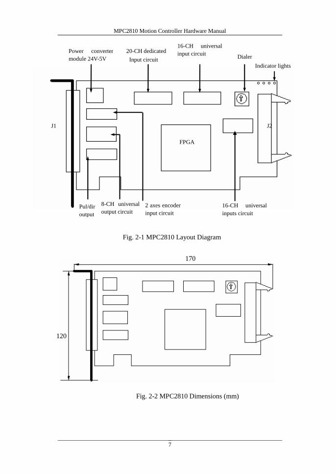
170
120
Fig. 2-2 MPC2810 Dimensions (mm)
Power converter
module 24V-5V
8-CH universal
output circuitPul/dir
output
2 axes encoder
input circuit
20-CH dedicated
Input circuit
16-CH universal
input circuit
16-CH universal
inputs circuit
FPGA
J1 J2
Indicator lights
Dialer
Fig. 2-1 MPC2810 Layout Diagram

MPC2810 Motion Controller Hardware Manual
8
(2)Breakout board-P62-01 for MPC2810
P62-01 Dimensions: (mm)
Mounting Hole Dimensions: 3mm.
Fig. 2-3 P62-01 Breakout Board
D61
D59
D57
D55
D53
D51
D49
D47
D45
D43
D62
D60
D58
D56
D54
D52
D50
D48
D46
D44
D1
D2
D3
D4
D5
D6
D7
D8
D9
D10
D11
D12
D13
D14
D15
D16
D17
D18
D19
D20
D41 D39 D37 D35 D33 D31 D29 D27 D25 D23 D21
D42 D40 D38 D36 D34 D32 D30 D28 D26 D24 D22
110mm
85mm
85
72
86110
Fig. 2-4 P62-01 Dimensions

MPC2810 Motion Controller Hardware Manual
9
(3)Breakout board-P37-05 for I/O extension board (mm)
Mounting Hole Dimensions: 3.5mm.
(4)Breakout board-P62-02 for MPC2810
Fig. 2-5 P37-05 Breakout Board
76
91
68.581
CN2 CN1
CN3
ENC1
AXIS1
ENC2
CN5 CN4
AXIS2
AXIS3 AXIS4
135
145
120130
Fig. 2-6 P62-02 Breakout Board

MPC2810 Motion Controller Hardware Manual
10
2.3 Hardware InstallationPC minimum hardware requirements:
X86 compatible PC with PCI slot
586+ CPU
256M+ Memory
Hardware Installation Steps:
1) Plug motion control card to the PCI-slot of the PC.
2) Connect the motion control card to the Breakout board
3) Connect the motor to motor drive
4) Connect motor drive to Breakout board
2.4 Software Installation
The motion control card can be operated under either Win2000 or WinXP
operating systems. Windows can automatically detect the MPC2810 when
plugged into the PC, and its Plug-and-Play capability will automatically install
the card. When you see the pop-up dialog box indicating that new device is
found, please click “cancel”and install the driver, function storehouse and demo
programs as following steps:
1) Click “Cancel” when the system indicates “Unknown PCI Device”
found.
Do not touch any controller circuits or plug-pull controller until you touch a
grounded metal object to discharge the electrostatic charge of your body.
Failure to follow this instruction could result in board damages.Caution
Execute the trial run without connecting the motor to the machine
system. Adjust the parameters of control card and motor drives, then
integrate the motor. After checking the setup operating correctly,
connect to the machine system again. Failure to follow this instruction
could result in injuries.Danger

MPC2810 Motion Controller Hardware Manual
11
2) Run setup program under root directory of installation CD. Then click
“Next”to continue the installation.
3) Select components to be installed.
Fig. 2-7 Welcome window
Fig. 2-8 Select components window

MPC2810 Motion Controller Hardware Manual
12
4) Select the destination location of installation files. Default path:
C:\Program Files\MPC2810. Click Browse to choose a preferred
path.
5) Click Next to start the installation.
Fig. 2-9 Choose destination location window

MPC2810 Motion Controller Hardware Manual
13
6) Finish the installation. Click Finish to complete the installation.
7) When the installation completed, system will indicate to restart the
Fig. 2-10 Copying files
Fig. 2-11 Installation completed

MPC2810 Motion Controller Hardware Manual
14
computer. Click OK to have the system restarted immediately. If you
want to restart the system later, click Cancel. MPC2810 can only be
used after the system restarted.
8) To check if the installation completed successfully, open the MPC2810
folder located in destination path. You can see following files.
A. Demonstration programs in “Demo”directory:
a) Sub-directory “VBDemo”: source code VB examples (“Demo1”
and “Demo2”);
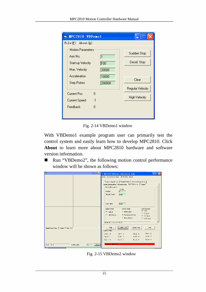
Run “VBDemo1.exe”, following dialog box pops up:
Fig. 2-12 Restart indication dialog box
Fig. 2-13 MPC2810 directory structure
MPC2810 Motion Controller Hardware Manual
15
With VBDemo1 example program user can primarily test the
control system and easily learn how to develop MPC2810. Click
About to learn more about MPC2810 hardware and software
version information.
Run “VBDemo2”, the following motion control performance
window will be shown as follows:
Fig. 2-14 VBDemo1 window
Fig. 2-15 VBDemo2 window

MPC2810 Motion Controller Hardware Manual
16
Motion track and speed curve are shown in the left frame. Parameters
settings on the linear/circular interpolation, the jogging motion and the
encoder are shown in the right frame. The frame OTHERS is used for
testing universal I/Os and special inputs.
b) 7 demonstration programs in sub-directory VCDemo: (All include
source code except VCDemo3)
“VCDemo1” and “VCDemo2”. “VCDemo1” is the VC static
loading dynamic link library example; “VCDemo2” is VC
dynamic loading dynamic-link-library example. Windows of
VCDemo1 and VCDemo2 are the same as follows:
Motion track will be shown on the left-side in the window, while parameter
settings shown on the right-side in the window.
Fig. 2-16 VCDemo1/VCDemo2 window

MPC2810 Motion Controller Hardware Manual
17
“VCDemo3”provides no source code. It can read *.DXF file, test
I/O & commands. (Refer to Chapter4)
“CmdMove1” demonstrates batch processing and short line
segments tracking examples.
“HandwheelorGearHandle”demonstrates manual pulse input and
electronic gearing examples.
Fig. 2-17 CmdMove1 window

MPC2810 Motion Controller Hardware Manual
18
“InterruptHandle”demonstrates event handling example.
Fig. 2-18 HandwheelorGearHandle window
Fig. 2-19 InterruptHandle window

MPC2810 Motion Controller Hardware Manual
19
“FastMoveDemo” demonstrates how to apply T-curve, S-curve
and custom acceleration-deceleration to fast motion when
batching processing.
B. Develop directory: MPC2810 driver programs and functions
storehouse.
a) Sub-directory “Common”: MPC2810 driver program and
functions storehouse;
b) Sub-directory “VB”: Module file MPC2810.bas used for
developing VB execution program
c) Sub-directory “VC”: file used for dynamically loading dynamic
link library(“LoadMPC2810.cpp” and “LoadMPC2810.h”) and
file used for static and dynamic link library (“MPC2810.h”and
Fig. 2-20 FastMoveDemo window

MPC2810 Motion Controller Hardware Manual
20
“MPC2810.lib”).
C. Reference Doc: Hardware Manual and Software (Programming)
Manual.
2.5 Uninstall software
There are two ways to uninstall the MPC2810 program:
1) Run UNWISE.exe in the MPC2810 folder.
2) Control Panel Run “Add/Remove Programs” to uninstall the
MPC2810 program.
2.6 Software Update
Please update the driver and/or the function library through our website,
http://www.leetro.com. The later version will be compatible with former ones.
The updating procedure is:
1. Close all program
2. Uninstall the former program
3. Run the later setup program
4. If it is developed by Visual Basic6.0, please update “MPC2810.dll” and
“MPC2810.bas”in the Microsoft Visual Basic Project.
5. If it is developed by Visual C++6.0, please update “MPC2810.dll”,
“MPC2810.lib”and “MPC2810.h”in the Microsoft Visual C++ Project in
the mode of implicit invocation.
In the mode of explicit invocation, please update “MPC2810.dll”,
“MPC2810.lib”, “LoadMPC2810.h” and “LoadMPC2810.cpp” in the
Microsoft Visual C++ Project.

MPC2810 Motion Controller Hardware Manual
21
3 How to Use
3.1 Parameter Setup
The Dialer (U55) on the control card can be used for setting the local ID of each
card if multi cards are applied. The value ranges from 0x0H to 0xFH. Please
refer to the Dialer and local ID correspondence table 3-1.
Fig. 3-1 U55 Dialer
Table 3-1 Dialer and Local ID Correspondence Table
Value of Dialer Local ID No. (Card No.)
0x0H 1
0x1H 2
0x2H 3
0x3H 4
Maximum 4 cards can be used. Maximum ID number should be 0x3H.
If only one card is used, the ID should be 0x0H (default setting).
If four cards are used, 0x0H should be the ID of the first card, 0x1H to the
second card, 0x2H to the third card, and 0x3H to the fourth card.
When it is applied in multi-MPC2810, the coupling relationship between card
and axis numbers are:
Card 1: Axis 1 –4
Card 2: Axis 5 –8
Card 3: Axis 9 –12
Card 4: Axis 13 –16
The functions of batch processing and look-ahead are only valid in axis 1-4.
0
4
8
C

MPC2810 Motion Controller Hardware Manual
22
3.2 Signal Interface
3.2.1 Breakout board-P62-01
Fig. 3-2 P62-01 Breakout board Layout Diagram
Table 3-2 Breakout board Interface Description
P62-0162-pin
cableName Description
D1 42 DCV5V
+5V output(max current:500mA), common
ground with DCV24V, can be
disconnected
D2 21 DCV24V +24V, input (Compulsory)
D3 20 OGND 24V GND, input (Compulsory)
D4 62 SD1 Axis-1 Ramp-down Signal
D5 41 EL1- Axis-1 Reverse Limit Signal
D6 19 EL1+ Axis-1 Forward Limit Signal
D7 61 ORG1 Axis-1 Homing Signal
D8 40 SD2 Axis-2 Ramp-down Signal
D9 18 EL2- Axis-2 Reverse Limit Signal
D61
D59
D57
D55
D53
D51
D49
D47
D45
D43
D62
D60
D58
D56
D54
D52
D50
D48
D46
D44
D1
D2
D3
D4
D5
D6
D7
D8
D9
D10
D11
D12
D13
D14
D15
D16
D17
D18
D19
D20
D41 D39 D37 D35 D33 D31 D29 D27 D25 D23 D21
D42 D40 D38 D36 D34 D32 D30 D28 D26 D24 D22

MPC2810 Motion Controller Hardware Manual
23
D10 60 EL2+ Axis-2 Forward Limit Signal
D11 39 ORG2 Axis-2 Homing Signal
D12 17 SD3 Axis-3 Ramp-down Signal
D13 59 EL3- Axis-3 Reverse Limit Signal
D14 38 EL3+ Axis-3 Forward Limit Signal
D15 16 ORG3 Axis-3 Homing Signal
D16 58 SD4 Axis-4 Ramp-down Signal
D17 37 EL4- Axis-4 Reverse Limit Signal
D18 15 EL4+ Axis-4 Forward Limit Signal
D19 57 ORG4 Axis-4 Homing Signal
D20 36 ALM Alarm Signal
D21 14 IN17 Universal input 17
D22 56 IN18 Universal input 18
D23 35 -- Reserved
D24 13 -DIN1 Encoder A1- (up/down pulse: Pul 1-)
D25 55 +DIN1 Encoder A1+ (up/down pulse: Pul 1+)
D26 54 -DIN2 Encoder B1- (up/down pulse: Dir 1-)
D27 34 +DIN2 Encoder B1+( up/down pulse: Dir1+)
D28 33 -DIN3 Encoder Z1-
D29 12 +DIN3 Encoder Z1+
D30 11 -DIN4 Encoder A2- (up/down pulse: Pul 2-)
D31 53 +DIN4 Encoder A2+( up/down pulse: Pul 2+)
D32 52 -DIN5 Encoder B2- (up/down pulse: Dir 2-)
D33 32 +DIN5 Encoder B2+ (up/down pulse: Dir 2+)
D34 31 -DIN6 Encoder Z2-
D35 10 +DIN6 Encoder Z2+
D36 COM1_8 Protect circuit, connected to +24V
D37 30 OUT1 Universal output-1
D38 51 OUT2 Universal output-2
D39 50 OUT3 Universal output-3
D40 8 OUT4 Universal output-4
D41 49 — — Reserved
D42 29 OUT5 Universal output-5
D43 7 OUT6 Universal output-6
D44 28 OUT7 Universal output-7
D45 48 OUT8 Universal output-8

MPC2810 Motion Controller Hardware Manual
24
D46 27 -DOUT1 Axis-1 direction-
D47 6 +DOUT1 Axis-1 direction +
D48 5 -DOUT2 Axis-1 pulse -
D49 47 +DOUT2 Axis-1 pulse +
D50 26 -DOUT3 Axis-2 direction -
D51 4 +DOUT3 Axis-2 direction +
D52 46 -DOUT4 Axis-2 pulse -
D53 25 +DOUT4 Axis-2 pulse +
D54 45 -DOUT5 Axi-3 direction -
D55 3 +DOUT5 Axis-3 direction +
D56 2 -DOUT6 Axis-3 pulse -
D57 24 +DOUT6 Axis-3 pulse +
D58 44 -DOUT7 Axis-4 direction -
D59 23 +DOUT7 Axis-4 direction +
D60 1 -DOUT8 Axis-4 pulse -
D61 43 +DOUT8 Axis-4 pulse +
D62 22 — — reserve
3.2.2 Universal I/O Extension Cable-C4037
16 universal inputs and 16 universal outputs can be extended with the installation
of C4037. Connect MPC2810 to external 37-pin cable through the C4037.
For the convenience of wiring, the I/O extension Breakout board P37-05 can be
used.
Table 3-3 P37-05 Interface Description
P37-05
Breakout
board
37-pin
CableName Description
P19 19 IN1 Universal input-1
P37 37 IN2 Universal input-2
P18 18 IN3 Universal input-3
P36 36 IN4 Universal input-4
P17 17 IN5 Universal input-5
P35 35 IN6 Universal input-6
P16 16 IN7 Universal input-7
P34 34 IN8 Universal input-8
P15 15 IN9 Universal input-9

MPC2810 Motion Controller Hardware Manual
25
P33 33 IN10 Universal input-10
P14 14 IN11 Universal input-11
P32 32 IN12 Universal input-12
P13 13 IN13 Universal input-13
P31 31 IN14 Universal input-14
P12 12 IN15 Universal input-15
P30 30 IN16 Universal input-16
P11 11 OUT9 Universal output-9
P29 29 OUT10 Universal output-10
P10 10 OUT11 Universal output-11
P28 28 OUT12 Universal output-12
P9 9 OUT13 Universal output-13
P27 27 OUT14 Universal output-14
P8 8 OUT15 Universal output-15
P26 26 OUT16 Universal output-16
P7 7 COM9_16 Protect circuit, connected to +24V
P25 25 DCV24 Output +24V, output current to 200mA
P6 6 OUT17 Universal output-17
P24 24 OUT18 Universal output-18
P5 5 OUT19 Universal output-19
P23 23 OUT20 Universal output-20
P4 4 OUT21 Universal output-21
P22 22 OUT22 Universal output-22
P3 3 OUT23 Universal output-23
P21 21 OUT24 Universal output-24
P2 2 COM17_24 Protect circuit, connected to +24V
P20 20 DCV24 Output +24V, output current to 200mA
P1 1 OGND Output 24V GND

MPC2810 Motion Controller Hardware Manual
26
3.2.3 Breakout board-P62-02
Fig.3-3 P62-02 Breakout board Layout Diagram
Table 3-4 P62-02 Interface Description
Connectors Description
CN1 Connected to MPC2810’s DB62 interface
CN2 Connected to C4037’s DB37 interface
CN3 24-pin for universal outputs
CN4 18-pin for universal inputs and alarm input
CN5 24V power supply
ENC1 Encoder-1
ENC2 Encoder-2
AXIS1 Axis-1 Control Interface (pulse, direction, origin, limits, Ramp-down)
AXIS2 Axis-2 Control Interface (pulse, direction, origin, limits, Ramp-down)
AXIS3 Axis-3 Control Interface (pulse, direction, origin, limits, Ramp-down)
AXIS4 Axis-4 Control Interface (pulse, direction, origin, limits, Ramp-down)
Table 3-5 Connector CN3 Description
Pin # Description
O24 Universal output-24
CN2 CN1
CN3
ENC1
AXIS1
ENC2
CN5 CN4
AXIS2
AXIS3 AXIS4
135
145
120130

MPC2810 Motion Controller Hardware Manual
27
O23 Universal output-23
O22 Universal output-22
O21 Universal output-21
O20 Universal output-20
O19 Universal output-19
O18 Universal output-18
O17 Universal output-17
O16 Universal output-16
O15 Universal output-15
O14 Universal output-14
O13 Universal output-13
O12 Universal output-12
O11 Universal output-11
O10 Universal output-10
O9 Universal output-9
O8 Universal output-8
O7 Universal output-7
O6 Universal output-6
O5 Universal output-5
O4 Universal output-4
O3 Universal output-3
O2 Universal output-2
O1 Universal output-1
COM1-8 Protect circuit, connected to +24V
Table 3-6 Connector CN4 Description
Pin # Description
I18 Universal input-18
I17 Universal input-17
I16 Universal input-16
I15 Universal input-15
I14 Universal input-14
I13 Universal input-13
I12 Universal input-12
I11 Universal input-11
I10 Universal input-10

MPC2810 Motion Controller Hardware Manual
28
I9 Universal input-9
I8 Universal input-8
I7 Universal input-7
I6 Universal input-6
I5 Universal input-5
I4 Universal input-4
I3 Universal input-3
I2 Universal input-2
I1 Universal input-1
ALM Alarm input
Table 3-7 Connector CN5 Description
Pin # Description
GND 24V GND, input (Compulsory)
DC24V +24V, input (Compulsory)
Table 3-8 Connector ENC Description
ENC1 pin # Description ENC2 pin # Description
A1+ Encoder A1+ A2+ Encoder A2+
A1- Encoder A1- A2- Encoder A2-
B1+ Encoder B1+ B2+ Encoder B2+
B1- Encoder B1- B2- Encoder B2-
Z1+ Encoder Z1+ Z2+ Encoder Z2+
Z1- Encoder Z1- Z2- Encoder Z2-
GND 24V GND GND 24V GND
Table 3-9 Connectors AXIS1,AXIS2 Description
AXIS1 pin # Description AXIS2 pin # Description
D1+ Axis-1 direction+ D2+ Axis-2 direction+
D1- Axis-1 direction- D2- Axis-2 direction-
P1+ Axis-1 pulse+ P2+ Axis-2 pulse+
P1- Axis-1 pulse- P2- Axis-2 pulse-
DC5V +5V output (reserve) DC5V +5V output (reserve)
E1+ Axis-1 Forward Limit E2+ Axis-2 Forward Limit
E1- Axis-1 Reverse Limit E2- Axis-2 Reverse Limit
ORG1 Axis-1 Homing ORG2 Axis-2 Homing

MPC2810 Motion Controller Hardware Manual
29
SD1 Axis-1 Ramp-down SD2 Axis-2 Ramp-down
Table 3-10 Connectors AXIS3、AXIS4 Description
AXIS3 pin # Description AXIS4 pin # Description
D3+ Axis-3 direction+ D4+ Axis-4 direction+
D3- Axis-3 direction- D4- Axis-4 direction-
P3+ Axis-3 pulse+ P4+ Axis-4 pulse+
P3- Axis-3 pulse- P4- Axis-4 pulse-
DC5V +5V output (reserve) DC5V +5V output (reserve)
E3+ Axis-3 Forward Limit E4+ Axis-4 Forward Limit
E3- Axis-3 Reverse Limit E4- Axis-4 Reverse Limit
ORG3 Axis-3 Homing ORG4 Axis-4 Homing
SD3 Axis-3 Ramp-down SD4 Axis-4 Ramp-down
3.3 Connection
3.3.1 Connect MPC2810 to P62-01
Power off the PC
Plug MPC2810 into the PCI-slot of the PC
Connect JP1 interface of MPC2810 to J1 interface of P62-01 with
the 62-pin shielded cable as shown in figure 3-3:
JP1
MPC2810Shielded cable
P62-01
Fig. 3-4 Connect Motion Control Card to Breakout Board
J1
MPC2810 Motion Controller Hardware Manual
30
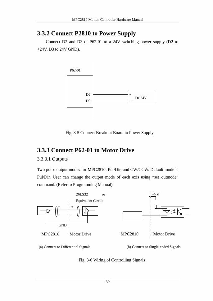
3.3.2 Connect P2810 to Power Supply
Connect D2 and D3 of P62-01 to a 24V switching power supply (D2 to
+24V, D3 to 24V GND).
3.3.3 Connect P62-01 to Motor Drive
3.3.3.1 Outputs
Two pulse output modes for MPC2810: Pul/Dir, and CW/CCW. Default mode is
Pul/Dir. User can change the output mode of each axis using “set_outmode”
command. (Refer to Programming Manual).
Fig. 3-5 Connect Breakout Board to Power Supply
P62-01
+
-DC24V
D2
D3
Fig. 3-6 Wiring of Controlling Signals
26LS32 or
Equivalent Circuit
MPC2810 Motor Drive
(a) Connect to Differential Signals
MPC2810 Motor Drive
(b) Connect to Single-ended Signals
+ +
- -
+5V
GND

MPC2810 Motion Controller Hardware Manual
31
1) Pul/Dir Mode
(2)CW/CCW Mode
Output Mode Pin CW CCW
Pulse
+
Direction
D46~D61
CW Pulse
+
CCW Pulse
D46~D61
(a) Differential Pul/Dir Mode
P62-01
D47
D46
Motor Drive
DIR+
DIR-
D49
D48
PULSE+
PULSE-
D47
D49
(b) Single-ended Pul/Dir Mode
P62-01 Motor Drive
DIR
PULSE
(a) Differential Pul/Dir Mode
P62-01
D47
D46
Motor Drive
DIR+
DIR-
D49
D48
PULSE+
PULSE-
(b) Single-ended CW/CCW Mode
P62-01 Motor Drive
DIR
PULSE
Fig. 3-7 Pul/Dir Output
Fig. 3-8 CW/CCW Output
Dir Signal
Pul Signal
CCW
CW
CCW
CW
D47
D49
Dir Signal
Pul Signal
Fig. 3-9 Pulse Output

MPC2810 Motion Controller Hardware Manual
32
3.3.3.2 Connect Encoder Inputs
2-CH encoder interfaces receiving A-phase, B-phase and Z-phase signals areavailable. D28, D29 (axis-1) and D34, D35 (axis-2) function as the differentialports for encoder latching inputs once the encoder latching functionalityactivated. Please refer to Fig.3-10, the connection diagram. Fig. 3-11 shows theconnection example provided encoder latch signals are single-ended.
Up/down pulse mode: Connect external pulse signal to the pulse input port ofcorresponding A-phase, and the external direction signal to pulse input port ofcorresponding B-phase.
26LS31
26LS31
26LS31
MPC2810 Encoder
Fig. 3-10 Connection Diagram of Encoder Inputs (Differential)
EA+
EA-
EB+
EB-
EZ+
EZ-
D25
D24
D27
D26
D29
D28
+5VMPC2810 Encoder
Fig.3-11 Connection Diagram of Encoder Inputs(Single-ended)
EA
D25
D24
D27
D26
D29
D28
EB
EZ

MPC2810 Motion Controller Hardware Manual
33
3.3.3.3 Connect Dedicated Inputs
Dedicated switch inputs include: limit, Ramp-down, homing and external alarm
signals. The switch could be contact-switch or NPN-output sensor proximity
switch. The connection diagram is as follows.
No dedicated switch outputs for MPC2810. User can set universal output1~4 as
comparative position output ports using the command enable_io_pos
3.3.3.4 Connecting Universal I/O
1) Universal Inputs Loop
Alarm input, limit input, homing input and Ramp-down
signal are default normally-close (making a short-circuit
to 24V GND if the inputs are not in use)
+- DC24/12
D3
D2
D5 or D6
D7
D20
NC alarm switch
NC origin switch
NC limit switch
NC deceleration switch
D4
MPC2810
Fig.3-12 Dedicated Inputs Connection

MPC2810 Motion Controller Hardware Manual
34
(2) Universal Output Loop
Open-collector output of MPC2810 can be connected to relay, and photo coupler.
The max output current is 200mA, voltage is 24V. It can be used as switch inputs
of servo system (Servo-ON, Error Counter Reset) or be used for driving
intermediate relay or photo coupler of 24DCV.
DC24/12+-
D3
D2
MPC2810
(a) Contact-Switch
Fig.3-13 GI Connection Diagram
(b) NPN Switch
Fig.3-14 Universal Input Connection
DC24/12+-
D3
D2
MPC2810
Signal Input
DC24-
+
D36
D3
Output
R
(a) Drive Photo Coupler
Fig.3-15 General Output Connection
MPC2810
ULN2803
Photo Coupler
Input
输入口

MPC2810 Motion Controller Hardware Manual
35
(b) Drive Relay
Fig. 3-16 GO Connection Diagram
R
ULN2803 DC24-
+
D36
D3
Output
RelayMPC2810

MPC2810 Motion Controller Hardware Manual
36
4 System Debugging
Debugging program can be found in the installation path. Before using the
debugging software, please make sure the system hardware is set up correctly
and connected well. Debugging software is to test if the system can work
normally, confirm if the connection is all right, and track some simple motions.
4.1 Destination path
When software installation completed, folder MPC2810 will be automatically
created (Default installation path: \ Program Files). The directory tree is as
follows:
Fig.4-1 MPC2810 Directory Tree
Find Demo3 the powerful debugging program following the path \Program

MPC2810 Motion Controller Hardware Manual
37
Files\MPC2810\Demo\VCDemo\VCDemo3. It is used for testing commands and
I/Os of MPC2810. Modules are built in VCDemo3 to process DXF file, 2D
trajectory motion can be generated with this program. Display resolution:
1024*768 (Recommend).
4.2 How to use the debugging program
After running VcDemo3.exe, five modules will present as fig. 4-2. They are
Continuous Trajectory, PTP Control, IO Test, Commands Test and Parameters
Setting
Fig. 4-2 Test Program
(1). Continuous Trajectory Module
This module is the default one after running the program. The button
could be applied to switch from other module.
Continuous
Trajectory
PTP Control IO Test Commands
Test
MPC2810 Motion Controller Hardware Manual
38
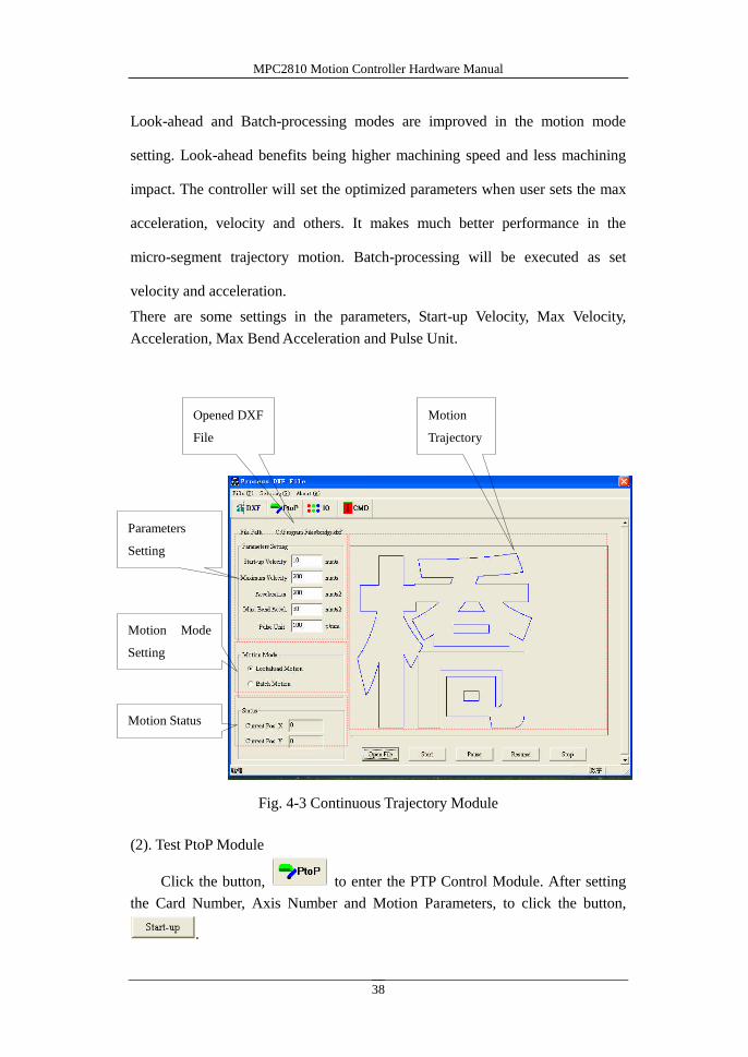
Look-ahead and Batch-processing modes are improved in the motion mode
setting. Look-ahead benefits being higher machining speed and less machining
impact. The controller will set the optimized parameters when user sets the max
acceleration, velocity and others. It makes much better performance in the
micro-segment trajectory motion. Batch-processing will be executed as set
velocity and acceleration.
There are some settings in the parameters, Start-up Velocity, Max Velocity,
Acceleration, Max Bend Acceleration and Pulse Unit.
Fig. 4-3 Continuous Trajectory Module
(2). Test PtoP Module
Click the button, to enter the PTP Control Module. After setting
the Card Number, Axis Number and Motion Parameters, to click the button,
.
Parameters
Setting
Opened DXF
File
Motion Mode
Setting
Motion
Trajectory
Motion Status

MPC2810 Motion Controller Hardware Manual
39
Fig. 4-4 Test PtoP Motion
(3). Test IO Module
Clicking the button is to enter IO Test Module.
Standard Inputs and Specific Inputs status will be shown as Fig. 4-5. Red
presents active-high. Green presents active-low. Blue presents error..
The Specific Inputs function will be enabled with the “check” symbol, which
is behind the signal shown as Fig. 4-5. Without “check” symbol, it is the
Standard Inputs.
“Negative Logic” and “Positive Logic” is for setting active-level in the
Specific Inputs.
24-channel Universal Outputs are on the bottom of window. Initially, they are
red, which means OFF. After clicking the button, the Red will be switched to the
Green. It means ON, which connects to the GND of inputted 24V.

MPC2810 Motion Controller Hardware Manual
40
Fig. 4-5 Test IO Module
(4). Test Command Module
Clicking the button is to enter the Test Command module. In this
module, users can test all functions of MPC2810.
After double-clicking the parameter column to enter the data, clicking the button
to carry out the command.
The command “get_last-err”enables finding out error reasons after matching it
in the error code list.

MPC2810 Motion Controller Hardware Manual
41
Fig. 4-6 Test Command
(5). System Setting Module
As Fig. 4-7 shown, Pulse Out Mode, Feedback and Home Mode will be set in
this window.
Fig. 4-7 System Setting

MPC2810 Motion Controller Hardware Manual
42
5 Typical Connection
5.1 Connect MPC2810 to DMD808 Stepper MotorDrive
D46
D47
D48
D49
D2
D3
Dir-
Dir+
Pul-
Pul+
Motion control cardStepper motor drive
DC24/12-
+
Axis-1 Direction+
Axis-1 Direction-
Axis-1 Pulse-
Axis-1 Pulse+
DCV24+
GND24

MPC2810 Motion Controller Hardware Manual
43
5.2 Connect MPC2810 to Panasonic MINAS ASeries Servo Motor Drive
D24 22
D25 21
D26 49
D27 48
D28 24
D29 23
D46 6
D47 5
D48 4
D49 3
D3
D2
Note: The encoder feedback pins can be disconnected.
Motion control card Servo motor driver
Encoder A1-
Encoder A1+
DC24/12
-+
Encoder B1-
Encoder B1+
Encoder Z1-
Encoder Z1+
Axis-1 Direction -
Axis-1 Direction +
Axis-1 Pulse -
Axis-1 Pulse +
GND24
DCV24+
OA-
OA+
OB-
OB+
OZ-
OZ+
SIGN2
SIGN1
PULS2
PULS1
29SRV-ON
13GND
41
7COM+
COM-