motors | automation | energy | transmission &...
TRANSCRIPT

W22 High Voltage IEC Three-Phase Electric Motors
Motors | Automation | Energy | Transmission & Distribution | Coatings
Technical Catalogue
European Market

www.weg.net
W22 High Voltage2
W22 Three-phase electric motor series. Designed for today. Protecting tomorrow.
W22 Line – High Voltage MotorsTaking the new designed platform of W22 line for LV motors, Weg developed the W22 High Voltage Motors.
The W22 High Voltage Motors take advantage of the same achieved key objectives introduced with the LV motors line:
Reduction noise and vibrations levels Increased energy efficiencies by using the same ventilation system and bearings Easy maintenance Flexible and modular design
Using electrical design optimizations software, the technical know-how in manufacturing compact pre-formed coils and making the required mechanical changings, WEG presents its new and competitive W22 High Voltage Motors Line.
W22 High Voltage Motors are available for supply voltages between 1,1kV up to 6,6kV.

www.weg.net
W22 High Voltage 3
W22 Three-phase electric motor series. Designed for today. Protecting tomorrow.
Visual Index
Table 1 - Visual Index
2.1 Frame Page 5
2.2 Eyebolts Page 5
2.4 Grounding lugs Page 6
2.5 Terminal box Page 6
2.8 Endshields Page 7
2.10 Fan cover Page 8
2.11 Nameplate Page 8
3.1 Cooling system Page 9
4.1 Shaft Page 10
4.2 Bearings Page 10
6.2 Sealing system Page 13
6.3 Painting Page 13

www.weg.net
W22 High Voltage4
Table of Contents
1. Standards.......................................................................................................................................................................................................................................................52. Construction details....................................................................................................................................................................................................................................5 2.1 Frame........................................................................................................................................................................................................................................................5 2.2 Eyebolts...................................................................................................................................................................................................................................................5 2.3 Points for vibration monitoring..........................................................................................................................................................................................................6 2.4 Earth terminals.......................................................................................................................................................................................................................................6 2.5 Terminal box...........................................................................................................................................................................................................................................6 2.6 Power supply connection leads......................................................................................................................................................................................................7 2.7 Accessory connection leads............................................................................................................................................................................................................7 2.8 Endshields...............................................................................................................................................................................................................................................7 2.9 Drains........................................................................................................................................................................................................................................................8 2.10 Fan cover...............................................................................................................................................................................................................................................8 2.11 Nameplates...........................................................................................................................................................................................................................................83. Cooling system and Noise level / Vibration level / Impact resistance........................................................................................................................................9 3.1 Cooling system and Noise Level.....................................................................................................................................................................................................9 3.2 Vibration level.......................................................................................................................................................................................................................................10 3.3 Impact resistance...............................................................................................................................................................................................................................10 4. Shaft / Bearings ....................................................................................................................................................................................................................................10 4.1 Shaft.........................................................................................................................................................................................................................................................10 4.2 Bearings ................................................................................................................................................................................................................................................10 4.2.1 Permissible thrust........................................................................................................................................................................................................................11 4.2.2 Bearing monitoring....................................................................................................................................................................................................................125. Mounting forms..........................................................................................................................................................................................................................................126. Degree of protection / Sealing system / Painting...........................................................................................................................................................................13 6.1 Degree of protection .........................................................................................................................................................................................................................13 6.2 Sealing system....................................................................................................................................................................................................................................13 6.3 Painting .................................................................................................................................................................................................................................................13 6.4 Tropicalized painting .........................................................................................................................................................................................................................147. Voltage / Frequency .................................................................................................................................................................................................................................148. Overload capacity......................................................................................................................................................................................................................................149. Ambient / Insulation .................................................................................................................................................................................................................................14 9.1 Space heaters......................................................................................................................................................................................................................................1510. Variable Speed Drive..............................................................................................................................................................................................................................15 10.1 Consideration regarding rated voltage......................................................................................................................................................................................15 10.2 Torque restrictions on variable speed drive applications...................................................................................................................................................16 10.3 Bearing insulation ............................................................................................................................................................................................................................16 10.4 Mechanical Speed ..........................................................................................................................................................................................................................1611. Tolerances for electrical data ..............................................................................................................................................................................................................1612. Standard features ...................................................................................................................................................................................................................................1713. Optional features .....................................................................................................................................................................................................................................1714. Electrical data ..........................................................................................................................................................................................................................................2015. Mechanical data .....................................................................................................................................................................................................................................2416. Terminal box drawings..........................................................................................................................................................................................................................2717. Drip cover data.........................................................................................................................................................................................................................................2818. Packaging..................................................................................................................................................................................................................................................2819. Inquiry / Order Check List....................................................................................................................................................................................................................29

www.weg.net
W22 High Voltage 5
1. Standards
IEC60034-1 Rotating electrical machines – Part 1: Rating and performance.IEC60034-2-1 Rotating electrical machines – Part 2-1: Standard methods for determining losses and efficiency from tests (excluding machines for traction vehicles).IEC60034-5 Rotating electrical machines – Part 5: Degrees of protection provided by the integral design of rotating electrical machines (IP code) - classification.IEC60034-6 Rotating electrical machines – Part 6: Methods of cooling (IC code).IEC60034-7 Rotating electrical machines – Part 7: Classification of types of enclosures and mounting arrangements (IM code).IEC60034-8 Rotating electrical machines – Part 8: Terminal markings and direction of rotation.IEC60034-9 Rotating electrical machines – Part 9: Noise limits.IEC60034-11-1 Rotating electrical machines – Part 11-1: Thermal protection.IEC60034-14 Rotating electrical machines – Part 14: Mechanical vibration of certain machines – Limits of vibration.IEC60072-1 Dimensions and output series for rotating electrical machines – Part 1: Frame numbers 56 to 400 and flange numbers 55 to 1080.
W22 motors meet the requirements and regulations of the latest version of the following Standards:
2. Construction detailsThe information included in this document refers to standardconstruction features and the most common variations for W22 motors in high voltage for general applications in frame sizes from IEC 315L to 355A/B.W22 motors for special and/or customised applications areavailable on request. For more information, please contact your WEG office or distributor.
2.1 Frame
The W22 frame (figure 1) is manufactured in FC-200 cast iron to provide high levels of mechanical strength to cater for themost critical applications. The cooling fins are designed to minimize the accumulation of liquids and dust over the motor.
Figure 1 – W22 Frame
The motor feet are completely solid for better mechanical strength (figure 2), allowing easier alignment and installation.
Figure 2 – Solid feet
Number of
eyeboltsDescription
2
Motors with feet and side or top mounted terminal box. These motors
have four threaded holes in the upper part of the frame for fastening
of the eyebolts (figure 3)
2
Motors without feet and with C or FF flange. These motors have four
threaded holes in the upper part of the frame for fastening of the
eyebolts and two more threaded holes in the bottom part
2.2 Eyebolts
The position of the eyebolts in motors W22 High Voltage is shown in table 2:
Table 2 - Eyebolts

www.weg.net
W22 High Voltage6
2.5 Terminal box
The terminal box of W22 motors is made with FC-200 castiron, which is the same material used to produce the frameand endshields. It is diagonally split for easier handling ofleads and connections.As standard the terminal box has a cable entrance extended gland plate that allows proper cable termination in most of high voltage cables. As an option it is available a longer cable entrance plate and a 45º oblique one. These arrangements are shown in figures 7.1 and 7.2. A threaded hole M63 x 1,5 is provided for cable fitting of cable gland.Also, as an option, the gland plates can be supplied undrilled.A second terminal box, with neutral connection, is available as option.
Figure 7.1 and 7.2 - Optional entrance plates
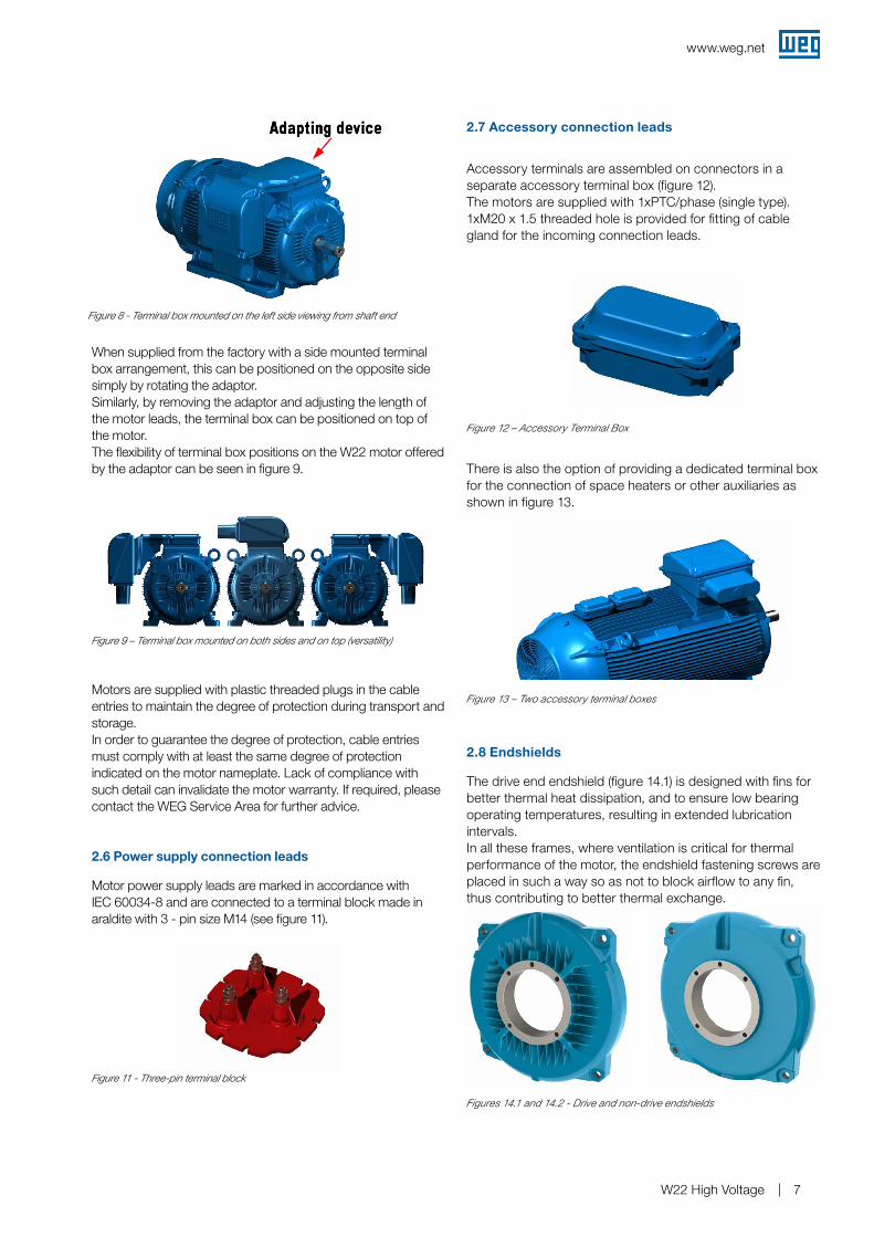
Terminal box is positioned towards the drive end of the motor and on top as standard.This arrangement allows improvement of the airflow over the cooling fins, thus reducing motor operating temperatures. Terminal box position on either the left or right hand side of the motor is possible through the use of an adaptor (see figure 8).
Two additional earth terminals on each side of the frame are provided to equalize electrical potential and provide greater safety for operators (figure 6).
Figure 6 - Earth terminals position in the frame
2.3 Points for vibration monitoring
To allow easy maintenance, specifically vibration checking, the 315 and 355 frames are designed with flat areas on both ends for better placement of the accelerometer (figure 4).These areas are both available in vertical and horizontal planes. Besides areas on the frame, W22 motors count on flat areas on the endshields for easier installation of accelerometers.As an option M8 threads for SPM accelerometers can be supplied.
Figure 4 - Flat surfaces for vibration monitoring on the back and front side
Figure 3 - Motor with four threaded holes for fastening of the eyebolts
Front side
2.4 Earth terminals
All frames are provided with one earth terminal located inside of the terminal box (see figure 5).
Figure 5 - Earth terminals in the terminal box
www.weg.net
W22 High Voltage 7
When supplied from the factory with a side mounted terminal box arrangement, this can be positioned on the opposite side simply by rotating the adaptor.Similarly, by removing the adaptor and adjusting the length of the motor leads, the terminal box can be positioned on top of the motor.The flexibility of terminal box positions on the W22 motor offered by the adaptor can be seen in figure 9.
Figure 9 – Terminal box mounted on both sides and on top (versatility)
Motors are supplied with plastic threaded plugs in the cable entries to maintain the degree of protection during transport and storage.In order to guarantee the degree of protection, cable entries must comply with at least the same degree of protection indicated on the motor nameplate. Lack of compliance with such detail can invalidate the motor warranty. If required, please contact the WEG Service Area for further advice.
2.6 Power supply connection leads
Motor power supply leads are marked in accordance withIEC 60034-8 and are connected to a terminal block made in araldite with 3 - pin size M14 (see figure 11).
Figure 11 - Three-pin terminal block
2.7 Accessory connection leads
Accessory terminals are assembled on connectors in a separate accessory terminal box (figure 12).The motors are supplied with 1xPTC/phase (single type). 1xM20 x 1.5 threaded hole is provided for fitting of cable gland for the incoming connection leads.
There is also the option of providing a dedicated terminal box for the connection of space heaters or other auxiliaries as shown in figure 13.
2.8 Endshields
The drive end endshield (figure 14.1) is designed with fins for better thermal heat dissipation, and to ensure low bearing operating temperatures, resulting in extended lubrication intervals.In all these frames, where ventilation is critical for thermal performance of the motor, the endshield fastening screws are placed in such a way so as not to block airflow to any fin, thus contributing to better thermal exchange.
Figure 12 – Accessory Terminal Box
Figure 13 – Two accessory terminal boxes
Figures 14.1 and 14.2 - Drive and non-drive endshields
Figure 8 - Terminal box mounted on the left side viewing from shaft end

www.weg.net
W22 High Voltage8
Figure 15 - Detail of the drain plug position on drive and endshield
2.10 Fan cover
The fan cover is made of FC-200 cast iron. The cast iron fan covers have an aerodynamic design, which results in a significant reduction in noise level and optimized airflow between frame fins for heat exchange improvement. Figure 16 shows the aerodynamic design of the cast iron fan cover.
Figure 16 – Fan cover
Figure 17 – Nameplate position
2.11 Nameplates The main nameplate supplies information determining motor construction and performance characteristics (see figure 18). Besides main nameplate, W22 High Voltage Motors are equipped with other information nameplates as follows:
Main terminal box indicative plate and warning plate (see figure 19) Auxiliary terminal box indicative plate with connection scheme for accessories (see figure 20) Sense of rotation nameplate - located over fan cover (see figure 21) Neutral terminal box indicative plate (when this optional is requested) 2nd auxiliary terminal box indicative plate (when this optional is requested)
Drain plug closedDrain plug open
1 – Manufacturing Country2 – Three phase3 – Motor rated power4 – Frame size5 – Rated operating voltage6 – Frequency7 – Rated operating current8 – Service factor9 – Full load speed (rpm)10 – Power factor 11 – Service duty12 – Ambient temperature 13 – Insulation class14 – Temperature rise15 – Degree of protection16 – Altitude17 – Motor weight18 – Connection diagram Y connection19 – Non-drive end bearing specification and amount of
grease20 – Drive end bearing specification and amount of grease21 – Type of grease for bearings22 – Relubrication intervals in hours 23 – Certification labels
2.9 Drains
The endshields have holes for drainage of water that may condense inside of the frame. These holes are supplied with rubber drain plugs, in accordance with figure 15. These plugs leave the factory in the closed position and must be opened periodically to allow the exit of condensed water.
Figure 18 - Main nameplate
Figure 19 - Main terminal box plates

www.weg.net
W22 High Voltage 9
3. Cooling system and Noise level / Vibration level / Impact resistance
3.1 Cooling system and Noise level
The W22 standard high voltage motors are totally enclosed fan cooled (IC411), as per IEC 60034-6 (figure 22). Non-ventilated versions (TENV), air over (TEAO) and with forced ventilation TEFV (IC416) are available on request.
Figure 22 – Cooling system
Table 3 – Sound pressure levels for 50 Hz motors
Table 4 – Sound pressure levels for 60 Hz motors
IEC 50 HZ
FrameSound pressure level - dB(A)
2 Poles 4 Poles 6 Poles 8 Poles
315 L 78 74 68 68
355M/L 80 76 73 70
355A/B 83 76 73 70
IEC 60 HZ
FrameSound pressure level - dB(A)
2 Poles 4 Poles 6 Poles 8 Poles
315L 82 79 71 71
355M/L 84 81 77 75
355A/B 89 81 77 75
The noise level figures shown in tables 3 and 4 are taken at no load. Under load the IEC 60034-9 Standard foresees an increase of the sound pressure levels as shown in table 5.
Frame (mm) 2 poles 4 poles 6 poles 8 poles
H = 315 2 3 5 6
H = 355 2 2 4 5
Table 5 – Maximum expected increase of sound pressure level for loaded motors.
Note: These figures refer to operating frequencies of 50 Hz and 60 Hz.The global noise level can be reduced up to 2 dB (A) with the installation of a drip cover.
Figure 23 – Cooling system operation
W22 high voltage motors comply with IEC60034-9 Standard and the corresponding sound pressure levels. Tables 3 and 4 show sound pressure levels in dB(A) which are obtained upon tests at 50 Hz and 60 Hz.
The cooling system (fan, non drive endshield and fan cover) is designed to minimize the noise level and improve thermal efficiency (figure 23).
Figure 20 - Auxiliary terminal box plate
Figure 21 - Sense of rotation plate (Bidirectional)
www.weg.net
W22 High Voltage10
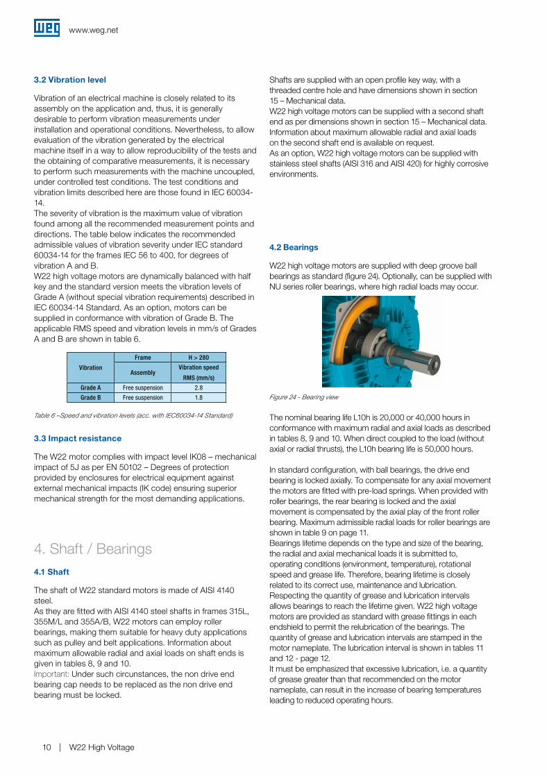
4.2 Bearings
W22 high voltage motors are supplied with deep groove ball bearings as standard (figure 24). Optionally, can be supplied with NU series roller bearings, where high radial loads may occur.
The nominal bearing life L10h is 20,000 or 40,000 hours in conformance with maximum radial and axial loads as described in tables 8, 9 and 10. When direct coupled to the load (without axial or radial thrusts), the L10h bearing life is 50,000 hours.
In standard configuration, with ball bearings, the drive end bearing is locked axially. To compensate for any axial movement the motors are fitted with pre-load springs. When provided with roller bearings, the rear bearing is locked and the axial movement is compensated by the axial play of the front roller bearing. Maximum admissible radial loads for roller bearings are shown in table 9 on page 11. Bearings lifetime depends on the type and size of the bearing, the radial and axial mechanical loads it is submitted to, operating conditions (environment, temperature), rotational speed and grease life. Therefore, bearing lifetime is closely related to its correct use, maintenance and lubrication. Respecting the quantity of grease and lubrication intervals allows bearings to reach the lifetime given. W22 high voltage motors are provided as standard with grease fittings in each endshield to permit the relubrication of the bearings. The quantity of grease and lubrication intervals are stamped in the motor nameplate. The lubrication interval is shown in tables 11 and 12 - page 12.It must be emphasized that excessive lubrication, i.e. a quantity of grease greater than that recommended on the motor nameplate, can result in the increase of bearing temperatures leading to reduced operating hours.
Shafts are supplied with an open profile key way, with a threaded centre hole and have dimensions shown in section 15 – Mechanical data. W22 high voltage motors can be supplied with a second shaft end as per dimensions shown in section 15 – Mechanical data.Information about maximum allowable radial and axial loadson the second shaft end is available on request.As an option, W22 high voltage motors can be supplied with stainless steel shafts (AISI 316 and AISI 420) for highly corrosiveenvironments.
Figure 24 - Bearing view
3.2 Vibration level
Vibration of an electrical machine is closely related to its assembly on the application and, thus, it is generally desirable to perform vibration measurements under installation and operational conditions. Nevertheless, to allow evaluation of the vibration generated by the electrical machine itself in a way to allow reproducibility of the tests and the obtaining of comparative measurements, it is necessary to perform such measurements with the machine uncoupled, under controlled test conditions. The test conditions and vibration limits described here are those found in IEC 60034-14.The severity of vibration is the maximum value of vibration found among all the recommended measurement points and directions. The table below indicates the recommended admissible values of vibration severity under IEC standard 60034-14 for the frames IEC 56 to 400, for degrees of vibration A and B.W22 high voltage motors are dynamically balanced with half key and the standard version meets the vibration levels of Grade A (without special vibration requirements) described in IEC 60034-14 Standard. As an option, motors can be supplied in conformance with vibration of Grade B. The applicable RMS speed and vibration levels in mm/s of Grades A and B are shown in table 6.
Table 6 –Speed and vibration levels (acc. with IEC60034-14 Standard)
3.3 Impact resistance
The W22 motor complies with impact level IK08 – mechanical impact of 5J as per EN 50102 – Degrees of protection provided by enclosures for electrical equipment against external mechanical impacts (IK code) ensuring superior mechanical strength for the most demanding applications.
Vibration
Frame H > 280
AssemblyVibration speed
RMS (mm/s)
Grade A Free suspension 2.8
Grade B Free suspension 1.8
4. Shaft / Bearings4.1 Shaft
The shaft of W22 standard motors is made of AISI 4140steel.As they are fitted with AISI 4140 steel shafts in frames 315L, 355M/L and 355A/B, W22 motors can employ roller bearings, making them suitable for heavy duty applications such as pulley and belt applications. Information about maximum allowable radial and axial loads on shaft ends is given in tables 8, 9 and 10.Important: Under such circunstances, the non drive end bearing cap needs to be replaced as the non drive end bearing must be locked.

www.weg.net
W22 High Voltage 11
Table 8.1 – Maximum permissible radial thrusts for ball bearings
Table 7 – ka factor
4.2.1 Permissible thrust
Note:L10h lifetime means that at least 90% of the bearings submitted to the maximum indicated loads will reach the number of hours indicated. The maximum admissible radial and axial loads for the standard configuration are shown in table 8, 9 and 10. The values of the maximum radial load consider axial load as nil. The values of the maximum axial load consider radial load as nil. For bearing lifetime in combined axial and radial loads condition contact WEG.
The radial force value Fr usually results from informationrecommended on catalogues of pulley/belts manufacturers.When this information is not available, the force Fr, underoperation, can be calculated based on the output power, oncoupling design characteristics with pulleys and belts and onthe type of application. So we have:
Where: Fr is the radial force caused by pulley and belt coupling [N];Pn is the motor rated power [kW];nn is the motor rated speed per minute [rpm];dp is the pitch diameter of the driven pulley [mm];ka is a factor that depends on belt tension and type of application (table 7).
Figure 25 - Radial and axial thrust on motor shaft
Groups and Basic Types of Application
ka Factor of the application
V-Belts Plane Belts
1(Fans and Blowers. Centrifugal Pumps. Winding machines. Compressors. Machine tools) with outputs up to 30 HP (22 kW)
2.0 3.1
2(Fans and Blowers, Centrifugal Pumps, Winding machines, Compressors, Machine tools) with outputs higher than 30 HP (22 kW), Mixers, Plungers, Printer Machines.
2.4 3.3
3
Presses, vibrating screens, Piston and screw compressor, pulverisers, helicoidal conveyors, woodworking machines, Textile machines, Kneading machines, Ceramic machines, Pulp and paper industrial grinders.
2.7 3.4
4
Overhead cranes, Hammer mills, Metal laminators, Conveyors, Gyratory Crushers, Jaw Crusher, Cone Crushers, Cage Mills, Ball Mills, Rubber Mixers, Mining machines, Shredders.
3.0 3.7
Maximum permissible radial thrust - 50 Hz – Fr in (kN) 20,000 hours
Frame2 poles 4 poles 6 poles 8 poles
L L/2 L L/2 L L/2 L L/2
315L 4.6 5.0 4.0 7.3 6.2 8.2 9.1 9.8
355M/L 4.8 5.1 8.5 9.3 9.6 10.4 11.6 12.6
355A/B 4.5 4.7 5.1 7.4 7.4 8.0 6.9 10.6
Fr = .ka (N)nn . dp
19,1 . 106 . Pn
Important: 1 - Special applicationsMotor operation under adverse operating conditions, such as higher ambient temperatures and altitudes or abnormal axial / radial loads, may require specific lubrication measures and alternative relubrication intervals to those indicated in the tables provided within this technical catalogue.
Maximum permissible radial thrust - 50 Hz – Fr in (kN) 40,000 hours
Frame2 poles 4 poles 6 poles 8 poles
L L/2 L L/2 L L/2 L L/2
315L 3.4 3.6 4.0 4.9 5.1 5.5 6.4 6.9
355M/L 3.3 3.6 5.8 6.3 6.5 7.1 8.2 8.9
355A/B 3.0 3.2 4.1 4.4 4.2 4.5 5.3 6.8
Radial thrust - Ball bearings
Table 8.2 – Maximum permissible radial thrusts for ball bearings
Table 9 – Maximum permissible radial thrusts for roller bearings Note: the figures given for roller bearings take into consideration shaft supplied with steel AISI 4140
Radial thrust - Roller bearings
2 - Roller bearings Roller bearings require a minimum radial load so as to ensurecorrect operation. They are not recommended for directcoupling arrangements, or for use on 2 pole motors.
3 - Motors with modified mounting configurationsFor motors supplied with horizontal mounting but workingvertically, lubrication intervals must be reduced by half.
4 - Figures for radial thrustsThe figures given in the tables below for radial thrusts take into consideration the point upon which the load is applied, either at the centre of the shaft (L/2) or at the end of the shaft (L), figure 25.
Radial thrust - Ball bearings
Maximum permissible radial thrust - 50 Hz - Fr in (kN) 20,000 or 40,000 hours
Frame4 poles 6 poles 8 poles
L L/2 L L/2 L L/2
315L 4 8.5 6.2 13.3 10.4 22.6
355M/L 15 31.7 13.7 28.9 14.3 30.1
355A/B 5.1 10.7 7.8 16.4 6.9 14.6

www.weg.net
W22 High Voltage12
Table 10.1 – Maximum pemissible axial thrusts for ball bearings
Axial thrust - Ball bearings
Maximum permissible axial thrust - 50 Hz - Fa in (kN) - 20,000 hours
Frame PolesHorizontal
Vertical with
shaft upwards
Vertical with shaft
downwards
Pushing Pulling Pushing Pulling Pushing Pulling
315L
2 3.0 2.2 1.1 5.0 5.7 0.44 4.5 3.7 1.4 8.2 8.9 0.66 5.2 4.4 1.9 9.5 10.3 1.28 6.3 5.5 3.4 10.0 10.8 2.6
355M/L
2 4.4 3.7 1.1 8.8 9.5 0.34 7.7 7.0 3.2 13.9 14.7 2.56 9.1 8.4 4.7 15.3 16.0 3.98 10.9 10.2 6.4 17.2 17.9 5.7
355A/B
2 4.1 3.3
On request4 6.8 6.06 7.8 7.08 9.8 9.0
Table 10.2 – Maximum permissible axial thrusts for ball bearings
Axial thrust - Ball bearings
Maximum permissible axial thrust - 50 Hz - Fa in (kN) - 40,000 hours
Frame PolesHorizontal
Vertical with
shaft upwards
Vertical with shaft
downwards
Pushing Pulling Pushing Pulling Pushing Pulling
315L
2 3.0 2.2 1.1 5.0 5.7 0.44 4.5 3.7 1.4 8.2 8.9 0.66 5.2 4.4 1.9 9.5 10.3 1.28 6.3 5.5 3.4 10.0 10.8 2.6
355M/L
2 3.1 2.4 0.6 6.7 7.5 0.24 5.5 4.7 1.9 1.1 11.6 1.26 6.3 5.6 2.8 11.8 12.7 2.08 7.6 6.8 3.8 13.2 13.7 2.9
355A/B
2 2.9 2.2
On request4 4.6 3.96 5.2 4.58 6.5 5.8
Table 11 – Lubrication intervals for ball bearings
Lubrication intervals
Lubrication intervals (hours)
Frame Poles Bearing 50 Hz 60 Hz
315
2 6314 5,000 4,0004
631911,000 8,000
6 16,000 13,0008 20,000 17,000
355
26314 5,000 4,0006316 4,000 On request
46322
9,000 6,0006 13,000 11,0008 19,000 14,000
Note: the amount of grease is indicated on the nameplate
Lubrication intervals (hours)
Frame Poles Bearing 50 Hz 60 Hz
3154
NU3197,000 5,000
6 12,000 9,0008 17,000 15,000
3554
NU3225,000 4,000
6 9,000 7,0008 14,000 13,000
Table 12 – Lubrication intervals for roller bearings
Note: the amount of grease is indicated on the nameplate
5. Mounting forms
The mounting configuration for the W22 high voltage motor lines comply with IEC standard 60034-7. Standard mounting forms and their variations are shown in table 13. After the designation, a characteristic letter is used to define the terminal box position. So, the mounting code IM B3 can be seen in WEG documents as detailed below (without IM code).B3L – terminal box on left hand side of the motor frameB3T – terminal box on top of the motor frameB3R – terminal box on right hand side of the motor frame
Note: The terminal box position is defined viewing the motor from the shaft end (figure 26).
Figure 26 – B3T mounting
Motors are supplied, as standard, in the B3T configuration, with the terminal box on top.
W22 high voltage motors can be equipped with bearing temperature detectors for monitoring bearing operating conditions. Usually a Pt100 temperature detector for continuous monitoring of bearing operating temperature is used.This type of monitoring is extremely important considering that it directly affects the grese and bearing lives particulary on motors equipped with greasing facilities.
4.2.2 Bearing monitoring

www.weg.net
W22 High Voltage 13
Table 13 – Mountings configurations
* Non-defined mountings by IEC 60034-7
Important:1. For motors mounted vertically shaft down fitting of a drip
cover is recommended to prevent ingress of small objects into the fan cover. The increase in total length of the motor with drip cover is shown in the section 17.
2. For vertically shaft up mounted motors installed in environments containing liquids, the use of a rubber slinger is recommended to prevent the ingress of liquid into the motor through the shaft.
Basic
mountingsOther type of mounting
IM B3 IM V5 IM V6 IM B6 IM B7 IM B8
IM 1001 IM 1011 IM 1031 IM 1051 IM 1061 IM 1071
IM B35 IM V15 IM V36 - *) - *) - *)
IM 2001 IM 2011 IM 2031 IM 2051 IM 2061 IM 2071
IM B34 IM V17 IM V37 - *) - *) - *)
IM 2101 IM 2111 IM 2131 IM 2151 IM 2161 IM 2171
IM B5 IM V1 IM V3
IM 3001 IM 3011 IM 3031
IM B14 IM V18 IM V19
IM 3601 IM 3611 IM 3631
6. Degree of protection / Sealing system / Painting6.1 Degree of protection
As per IEC 60034-5 Standard, the degree of protection of a rotating electrical machine consists of the letters IP (ingress protection), followed by two characteristic numerals, with the following meaning:a) First characteristic numeral: referred to protection of people
against or approach to live parts and against contacts with moving parts (other than smooth rotating shafts and the like) inside the enclosure and protection of the machine against ingress of solid and foreign objects.
b) Second characteristic numeral: protection of machines against harmful effects due to ingress of water.
W22 high voltage motors are supplied with degrees of protection in conformance with IEC 60034-5. As standard, they are IP55, wich means:a) First characteristic numeral 5: machine protected against
dust. The enclosure is protected against contact with moving parts. Ingress of dust is not totally prevented, but dust does not enter in sufficient quantity to interfere with satisfactory operation of the machine.
b) Second characteristic numeral 5: Machine protected against water jets. Water projected by a nozzle against the machine from any direction shall have no harmful effect.
6.2 Sealing system
The sealing system applied to the shaft of W22 high voltage motors is the exclusive WSeal®, which consists of a double lipped V’Ring with a metallic cap (see figure 27). This configuration operates like a labyrinth preventing ingress of water and dust into the motor.
Alternatively, W22 high voltage motors can be supplied with other sealing systems, for example, oilseal, tachonite labyrinth and the WEG exclusive W3Seal®, among others (see section 13 – Optional features).When fitted with flange, the recommended seal is lip seal (no contact with liquid) and oilseal (with contact with liquid).
Figure 27 – WSeal®
6.3 Painting
W22 high voltage motors are supplied as standard with WEG internal painting plan 203A, consisting of:
Primer: one coat with 20 to 55 μm of alkyd primer; Finishing: one coat with 30 to 40 μm of alkyd synthetic
enamel.
Figure 28 – WEG internal painting plan

www.weg.net
W22 High Voltage14
6.4 Tropicalized painting
The integrity of the insulation system is the primary consideration when determining the lifetime of an electric motor. High humidity can result in premature deterioration of the insulation system, therefore for any ambient temperature with relative humidity above 95%, it is recommended to coat all internal components of the motor with an epoxy painting, also known as tropicalization.W22 High Voltage Motors receive as standard a tropicalized painting.
This painting plan has a minimum resistance to the salt spray test of 240 hours in accordance with ASTM B 117/03 and may be used in motors applied in normal environments, slightly severe, sheltered or non-sheltered, for industrial use, with low relative humidity, normal temperature variations and the presence of SO2.
Note: This painting plan is not recommended for direct exposure to acid steam, alkalis, solvents and salty environments.Alternative painting plans are available on request, which are suitable to guarantee additional protection in aggressive environments, either protected or unprotected (see section 13 – Optional features).
7. Voltage / FrequencyIn IEC 60034-1 the combination of voltage and frequency variations are classified as Zone A or Zone B, as per figure 29.
Figure 29 - Rated voltage and frequency limits for electric motors
Voltage
Zone A
Frequency
Zone B (outside zone A)
Rating point
IEC 60034-1 states that the motor must be suitable to perform its main function (supply torque) continuously at Zone A. However, this motor may not fully meet its performance characteristics due to power supply voltage and frequency variation, which can result in temperature rise above the rated value.
T (°C)Altitude (m)
1000 1500 2000 2500 3000 3500 4000 4500 5000
10 0.97 0.92 0.88
15 0.98 0.94 0.90 0.86
20 1.00 0.95 0.91 0.87 0.83
25 1.00 0.95 0.93 0.89 0.85 0.81
30 1.00 0.96 0.92 0.90 0.86 0.82 0.78
35 1.00 0.95 0.93 0.90 0.88 0.84 0.80 0.75
40 1.00 0.97 0.94 0.90 0.86 0.82 0.80 0.76 0.71
45 0.95 0.92 0.90 0.88 0.85 0.81 0.78 0.74 0.69
50 0.92 0.90 0.87 0.85 0.82 0.80 0.77 0.72 0.67
55 0.88 0.85 0.83 0.81 0.78 0.76 0.73 0.70 0.65
60 0.83 0.82 0.80 0.77 0.75 0.73 0.70 0.67 0.62
65 0.79 0.76 0.74 0.72 0.70 0.68 0.66 0.62 0.58
70 0.74 0.71 0.69 0.67 0.66 0.64 0.62 0.58 0.53
75 0.70 0.68 0.66 0.64 0.62 0.60 0.58 0.53 0.49
80 0.65 0.64 0.62 0.60 0.58 0.56 0.55 0.48 0.44
Table 14 – Correction factors for altitude and ambient temperature
Pmax = Pnom x correction factor
8. Overload capacityAs per IEC 60034-1, motors with output power up to 315 kW are suitable for an overload 1.5 times the rated torque for 2 minutes.
9. Ambient / InsulationUnless otherwise specified, the rated power outputs shown in the electrical data tables within this catalogue refer to continuous duty operation S1, as per IEC 60034-1 and under the following conditions:
With ambient temperature range -20°C to +40°C
With altitudes up to 1000 metres above sea level For operating temperatures and altitudes differing from those above, the factors indicated in table 14 must be applied to the nominal motor power rating in order to determine the derated available output (Pmax).
The motor must also be suitable to perform its main function (supply torque) at Zone B. However, the performance characteristic changes will be greater than those operating at Zone A. The temperature rise will also be higher than that of rated voltage and frequency and that operating at Zone A. Prolonged operation near Zone B boundary is not recommended.

www.weg.net
W22 High Voltage 15
W22 motors are supplied with class F insulation and Class B (80 K) temperature rise at normal operating conditions (unless otherwise specified).The difference between the temperature rise of the class F insulation (105 K) and the temperature rise of the design (80 K) means that, in practice, W22 motors are suitable to supply output ratings above the rated values up to a limit where the temperature rise reaches the temperature rise value of the insulation class.The ratio between temperature rise and service factor is given by the equation below:
DTFINAL
≈ (F.S.)2 x DTINITIAL
Table 15 – Power and quantity of space heaters
Frame Quantities Rated power per heater (W)
315L 2 70
355M/L 355A/B 2 87
Upon service factor calculation, we can see that SF is approximately 1.15. This reserve of temperature also allows W22 motors with class B temperature rise (80 K) to operate continuously at: Up to 15% above its rated output power, considering 40°C
ambient temperature and 1.000 m.a.s.l. Up to 55°C ambient temperature, keeping the rated output
power Up to 3000 m.a.s.l., keeping the rated output power
Note: Please note that under these conditions combined ambient and temperature rise motors will reach class F limits.
Bearing lubrication intervals will change under operating conditions other than 40°C maximum ambient temperature and 1000 meters above sea level. Contact WEG for more information.
W22 High Voltage Motors insulation system consists mainly in:
Rectangular bare copper wire with 2 or 3 mica tapes (used in respect of the applied voltage) Coil main insulation with mica tapes Straight part of coil with conductive tape for voltages above 4160V Coil heads mechanical protection with polyester shrinking tape VPI system with polyesterimide resin of class H type
As an option W22 high voltage motors can be equipped with tubular space heaters of 230V. Other voltages can be also supplied as request.
The power rating and number of space heaters when fitted are indicated in table 15:
9.1 Space heaters
The use of space heaters are recommended in two situations:
Motors installed in environments with relative air humidity up to 95%, in which the motor may remain idle for periods greater than 24 hours;
Motors installed in environments with relative air humidity greater than 95%, regardless of the operating schedule. It should be highligthed that in this situation it is strongly recommended that an epoxy paint known as tropicalized painting is applied in the internal components of the motor. More information can be obtained in section 6.4.
10. Variable Speed Drive
10.1 Consideration regarding rated voltage
By request W22 high voltage motors can be supplied for inverter use with a rated voltage up to and included of 4160V.The limits to high voltage W22 motors are shown in the table 16, which demonstrates DOL and VSD driven (with reinforced insulation) capabilities.
Motor rated voltage Source Type
Coil insulation (phase to phase)
Main insulation(phase to ground)
Peak voltage
on motor terminals
dV/dt (*) on motor terminals
Peak voltage
on motor terminals
dV/dt (*) on motor terminals
1100V ≤
VNON ≤
4160V
Power Grid ≤ 5900V≤ 500
V/µs≤ 3400V
≤ 500
V/µs
PWM (**) ≤ 9300V≤ 2700
V/µs≤ 5400V
≤ 2700
V/µs
Table 16 – High voltage limits
(*) Definition according to NEMA MG1 - Part 30(**) Reinforced insulation for VSD operating
Notes:
1. The switching frequency must be limited to 5kHz. Switching frequencies above that accelerate the winding aging process and potentially damage the bearings.
2. If one of the above conditions is not followed accordingly (including the switching frequency), filter must be installed on VSD outlet.
3. It should be noticed that standard W22 high voltage motors do not comply with VSD supply.

www.weg.net
W22 High Voltage16
11. Tolerances for electrical data
The following tolerances are allowed in accordance with IEC 60034-1:
Efficiency (η)
-0.15 (1-η) for Pnom ≤ 150 kW /
-0.1 (1-η) for Pnom > 150 kW
Where η is a decimal number
Power factor
1 - cos Ø
6
Minimum 0.02 and Maximum 0.07Slip ± 20% for Pnom ≥ 1 kW and ± 30 % for Pnom < 1 kW
Starting current 20% (without lower limit)
Starting torque - 15% + 25%
Breakdown torque - 10 %
Moment of inertia ± 10 %
Table 18 - Tolerances for electrical data
10.2 Torque restrictions on variable speed drive applications
Self-ventilated variable speed drive motors have their torque limited at low frequencies due to the reduction in ventilation. Curves and derating tables must be applied to define the torque available (figure 30 / table 17).
Constant flux condition
Figure 30 – Derating curve for constant flux
Table 17 – Equation for torque definition at constant torque condition
Derating factor with temperature rise for the insulation class*
Interval Limited by Apply this equation
A 0.10 ≤ f/fn < 0.25 TR = (f/fn) + 0.60
B 0.25 ≤ f/fn < 0.50 TR = 0.40(f/fn) + 0.75
C 0.50 ≤ f/fn < 0.83 TR = 0.15(f/fn) + 0.87
D 0.83 ≤ f/fn ≤ 1.0 TR = 1.0
E f/fn > 1.0 TR = 1/(f/fn)
Derating factor to maintain temperature rise at sinusoidal source**
Interval Limited by Apply this equation
F 0.10 ≤ f/fn < 0.25 TR = (f/fn) + 0.50
G 0.25 ≤ f/fn < 0.50 TR = 0.40(f/fn) + 0.65
H 0.50 ≤ f/fn < 0.83 TR = 0.30(f/fn) + 0.70
I 0.83 ≤ f/fn ≤ 1.0 TR = 0.95
J f/fn > 1.0 TR = 0.95/(f/fn)
Note: The derating curves given in figure 30 are related to the temperature on motor winding and thermal class. These curves do not foresee thermal tolerance factor of the motors. They are intended to show the torque limitations for variable frequency drive motors.
(*) When the top curve is used (green), motor temperature rise will be limited by the temperature class of the insulation material. For example, for class F insulation motors, the temperature rise will be limited at 105 K. This curve can only be used for class F insulation and class B temperature rise motors in order to ensure that, when driven by a frequency drive, the temperature rise remains class F (above 80 and below 105 K).
(**) When the lower curve is used (blue), the motor temperature rise of the variable frequency drive will be the same driven by sinusoidal source. In other words, class F insulation motors with class B temperature rise will remain with class B temperature rise(≤ 80 K) even when driven by a variable frequency drive.
10.3 Bearing insulation
When VSD purpose motors are supplied the NDE bearing will be of insulated type and there will be a ground system between the shaft and frame on DE side. In alternative, by customer requested, the NDE insulated bearing can be replaced by an insulated NDE endshield.
10.4 Mechanical speed
As a general rule W22 high voltage motors VSD driven can operate up to 120% of synchronous speed.For different speed ranges a specific inquiry shall be sent to WEG.

www.weg.net
W22 High Voltage 17
12. Standard Features 13. Optional Features
S (Standard)O (Optional)NA (Not available)
IEC FRAME 315L 355M/L 355A/B
MECHANICAL FEATURES
Nameplate marking
Mounting B3T
Frame Material Cast Iron FC-200
Degree of protection IP55
Grounding Double grounding + additional (Inside terminal box)
Cooling method Tottaly enclosed fan cooled - IC411
Fan Material2P Polypropylene Aluminium
4 - 8P Aluminium
Fan Cover Material
Cast iron FC-200 for anti-fricton bear-ings without forced ventilation kit/steel
for sleeve bearing and anti-friction bearings with forced ventilation kit
Endshields Material Cast Iron FC-200
Drain hole Fitted with rubber frain plug
Bearings
Clearance D.E. C3
Clearance N.D.E. C3
Locating bearing configu-ration
DE bearing locked with inner and outer bearing caps and fitted with pre-load
springs in the NDE bearing
Drive End2P 6314 6316 6316
4 - 8P 6319 6322 6322
Non-Drive end2P 6314 6314 6314
4 - 8P 6316 6319 6319
Bearing Seal Wseal
Joint Seal Without
Lubrification
Type of grease Polyrex EM 103 (Exxon Mobile)
Grease fitting With grease fittings in DE and NDE bearings
Terminal Block With terminal block - 3 pins
Terminal Box Material Cast Iron FC-200
Accessory Terminal Box With accessory terminal box
Leads inlet
Main Terminal box
Thread size
1 x M63 x 1,5 (removable gland plate)
Auxilliary Termi-nal box
Thread size 1 x M20 x 1,5
Plug Plastic plug
Shaft
Material AISI 4140
Threaded 2PM20
M20 M20
hole 4 - 8P M24 M24
Vibration Grade A
Balance With half key
Nameplate Material Stainless steel AISI 304
PaintingPlan 203A
Colour RAL 5007
ELECTRICAL FEATURES
Voltage 1100 V to 6600 V
Winding
Material Copper
Impregnation VPI
Insulation class F (DT 80K / 105K)
Service factor 1.00
Rotor Aluminium die cast
Thermal protectionPTC, 1 per phase
(single type)
IEC FRAME 315L 355M/L 355A/BMECHANICAL OPTIONALS
Terminal box
2nd Auxiliary terminal box O O O
Terminal box with removable base S S S
Gland plate O O O
Terminal block
Terminal block - three-pin S S S
Terminal block - six-pin O O O
Cable glands
Plastic cable gland O O O
Brass cable gland O O O
Stainless steel cable gland O O O
Flange
Flange FF O O O
Flange FF (Superior) O NA NA
Flange FF (Inferior) O O NA
Flange C-DIN NA NA NA
Flange C-DIN (Superior) NA NA NA
Flange C-DIN (Inferior) NA NA NA
Flange C O O NA
Flange C (Superior) NA NA NA
Flange C (Inferior) O O NA
Fan
Polypropylene (2 and 4 poles) S S NA
Polypropylene (6 and 8 poles) NA NA NA
Conductive plastic NA NA NA
Aluminium (2 and 4 poles) O O S
Aluminium (6 and 8 poles) S S S
Cast iron O O O
Bearing
Ball bearing (D.E) S S S
Roller bearing (D.E) O O O
Ball bearing (N.D.E) S S S
Insulated drive end bearing O O O
Insulated non drive end bearing O O O
Bearing cap
Without bearing cap NA NA NA
With bearing cap S S S
Bearing sealing
Nitrillic rubber lip seal NA NA NA
Nitrillic rubber oil seal NA NA NA
Nitrillic oil seal with stainless steel spring NA NA NA
Nitrillic rubber oil seal double lip NA NA NA
Viton seal O O O
Viton oil seal O O O
Viton oil seal with stainless steel spring O O O
Labyrinth Tachonite O O O
W3Seal® O O O
www.weg.net
W22 High Voltage18
S (Standard)O (Optional)NA (Not available)
IEC FRAME 315L 355M/L 355A/BMECHANICAL OPTIONALS
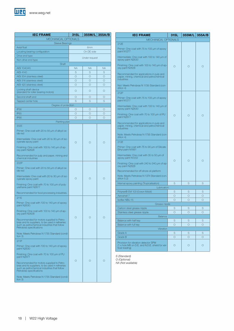
Sleeve Bearings
Axial float 6mm
Locating bearing configuration On DE side
Drive end typeUnder request
Non-drive end type
Shaft
AISI 1040/45 NA NA NA
AISI 4140 S S S
AISI 304 (stainless steel) O O O
AISI 316 (stainless steel) O O O
AISI 420 (stainless steel) O O O
Locking shaft device (standard for roller bearing motors) O O O
Second shaft end O O O
Tapped center hole S S S
Degree of protection
IP56 O O O
IP65 O O O
IP66 O O O
Painting plan
202E
O O O
Primer: One coat with 20 to 55 µm of alkyd ox-ide red
Intermediate: One coat with 20 to 30 µm of iso-cyanate epoxy paint
Finishing: One coat with 100 to 140 µm of ep-oxy paint N2628
Recommended for pulp and paper, mining and chemical industries
202P
O O O
Primer: One coat with 20 to 55 µm of alkyd ox-ide red
Intermediate: One coat with 20 to 30 µm of iso-cyanate epoxy paint
Finishing: One coat with 70 to 100 µm of poly-urethane paint N2677
Recommended for food processing industries.
211E
O O O
Primer: One coat with 100 to 140 µm of epoxy paint N2630.
Finishing: One coat with 100 to 140 µm of ep-oxy paint N2628
Recommended for motors supplied to Petro-bras and its suppliers, to be used in refineries such as petrochemical industries that follow Petrobras specifications
Note: Meets Petrobras N 1735 Standard (condi-tion 3)
211P
O O O
Primer: One coat with 100 to 140 µm of epoxy paint N2630
Finishing: One coat with 70 to 100 µm of PU paint N2677
Recommended for motors supplied to Petro-bras and its suppliers, to be used in refineries such as petrochemical industries that follow Petrobras specifications
Note: Meets Petrobras N 1735 Standard (condi-tion 3)
IEC FRAME 315L 355M/L 355A/BMECHANICAL OPTIONALS
212E
O O O
Primer: One coat with 75 to 105 µm of epoxy paint N1277
Intermediate: One coat with 100 to 140 µm of epoxy paint N2630
Finishing: One coat with 100 to 140 µm of ep-oxy paint N2628
Recommended for applications in pulp and paper, mining, chemical and petrochemical industries
Not: Meets Petrobras N 1735 Standard (con-dition 4)
212P
O O O
Primer: One coat with 75 to 105 µm of epoxy paint N1277
Intermediate: One coat with 100 to 140 µm of epoxy paint N2630
Finishing: One coat with 70 to 100 µm of PU paint N2677
Recommended for applications in pulp and paper, mining, chemical and petrochemical industries
Note: Meets Petrobras N 1735 Standard (con-dition 4)
213E
O O O
Primer: One coat with 75 to 90 µm of Silicate Ethyl paint N1661
Intermediate: One coat with 35 to 50 µm of epoxy paint N1202
Finishing: One coat with 240 to 340 µm of ep-oxy paint N2628
Recommended for off-shore oil platform
Note: Meets Petrobras N 1374 Standard (con-dition 5.2)
Internal epoxy painting (Tropicalisation) S S S
Lubrication
Polyrex® EM 103 (Exxon Mobil) S S S
Aeroshell 7 O O O
Isoflex NBU-15 O O O
Grease nipple
Carbon steel grease nipple S S S
Stainless steel grease nipple O O O
Balance
Balance with half key S S S
Balance with full key O O O
Vibration
Grade A S S S
Grade B O O O
Provision for vibration detector SPM (1 x hole M8 on D.E. and N.D.E. shield for ver-tical reading)
O O O

www.weg.net
W22 High Voltage 19
S (Standard)O (Optional)NA (Not available)
Notes: 1) Other optional features, on request.
2) Some combinations of optional features are not possible - please contact WEG
IEC FRAME 315L 355M/L 355 A/BMECHANICAL OPTIONALS
Drain
Rubber drain plug S S S
Plastic drain plug (open) - Automatic NA NA NA
Plastic drain plug (close) NA NA NA
Threaded drain plug O O O
Stainless steel drain plug O O O
T type drain plug O O O
Other mechanical optionals
Drip cover (recommended for vertical shaft down applications) O O O
Rubber slinger (recommended for vertical shaft up applications) O O O
Stainless steel hardware O O O
Grease outlet through the endshield O O O
IEC FRAME 315L 355M/L 355 A/BELECTRICAL OPTIONALS
Rotor
Copper Rotor O O O
Winding thermal protection
Bimetallic alarm thermal protector O O O
Bimetallic tripping thermal protector O O O
Pt100 two wires, one per phase O O O
Pt100 two wires, two per phase O O O
Pt100 three wires, one per phase O O O
Pt100 three wires, two per phase O O O
Alarm thermistor O O O
Tripping thermistor S S S
Bearing thermal protection
Bimetallic thermal protector O O O
Thermistor O O O
Pt100 two wires O O O
Pt100 three wires O O O
Space heaters
Space heaters2 x 70W O NA NA
2 x 87W NA O O
110-127 V O O O
230V O O O
220-240 V O O O
110-127 / 220-240 V O O O
380-480 V O O O
Rotation direction
Both S S S
Clockwise rotation direction O O O
Counter clockwise rotation direction O O O
Nameplate with indication of rotation direction S S S
Service factor
Service factor 1.00 S S S
Service factor 1.15 O O O
Insulation class
F S S S
H O O O
Forced ventilation kit
Forced ventilation kit with encoder provision (inform auxiliary motor voltage) O O O
Forced ventilation kit without encoder provi-sion (inform auxiliary motor voltage) O O O
Encoder O O O
Drive end side grounding brush O O O
Non drive end side grounding brush O O O

www.weg.net
W22 High Voltage20
14. Electrical Data
W22 High Voltage 3300V - 50Hz
Y 3300V/50Hz
Output
Frame IEC Tn (Nm) IS / In TS / Tn Tmax / TnInertia J
Kgm2
Allowable locked rotor time Cold/
Hot (s)
Weight KgSound dB(A)
rpm min-1
% of full load
In (A)kW HP Efficiency η Power Factor Cos j
50 75 100 50 75 100
II Pole - 3000 min-1
90 125 315L 289 6.2 1.2 2.3 1.10 44/20 1000 78 2970 91.5 92.8 92.9 0.76 0.83 0.86 19.7
110 150 315L 353 6.5 1.3 2.5 1.36 44/20 1050 78 2973 92.4 93.5 93.6 0.77 0.84 0.87 23.6
132 175 315L 423 6.5 1.3 2.5 1.53 44/20 1100 78 2973 93.1 94.0 94.0 0.77 0.84 0.87 28.2
150 200 315L 481 6.5 1.3 2.5 1.60 44/20 1200 78 2973 93.3 94.2 94.2 0.77 0.84 0.87 32.0
160 220 315L 514 6.5 1.3 2.5 1.66 44/20 1200 78 2974 93.6 94.4 94.4 0.77 0.84 0.87 34.1
185 250 315L 593 7.2 1.5 2.5 1.81 44/20 1300 78 2977 93.9 94.7 94.7 0.77 0.84 0.87 39.2
200 270 315L (1) 641 7.2 1.6 2.5 1.81 26/12 1300 78 2977 94.0 94.7 94.7 0.72 0.82 0.86 43.1
200 270 355M/L 642 6.8 1.4 2.5 3.07 44/20 1700 80 2976 93.8 94.6 94.7 0.80 0.86 0.88 42.0
220 300 355A/B 705 6.8 1.7 2.5 3.25 44/20 1800 83 2981 93.8 94.7 94.8 0.78 0.85 0.87 46.5
250 340 355A/B 801 6.8 1.7 2.5 3.69 44/20 1900 83 2981 94.2 95.0 95.1 0.78 0.85 0.87 52.9
260 350 355A/B 833 6.8 1.7 2.5 3.69 44/20 1900 83 2981 94.4 95.2 95.2 0.78 0.85 0.87 54.9
280 380 355A/B 897 6.8 1.7 2.5 4.13 44/20 2000 83 2982 94.6 95.3 95.3 0.78 0.85 0.87 59.1
300 400 355A/B 960 7.2 1.7 2.5 4.13 44/20 2000 83 2982 94.7 95.4 95.4 0.78 0.85 0.87 63.2
315 430 355A/B 1009 7.2 1.8 2.5 4.50 40/18 2100 83 2983 94.8 95.5 95.5 0.78 0.85 0.87 66.3
330 450 355A/B 1058 7.2 1.8 2.5 4.87 40/18 2200 83 2983 94.9 95.6 95.6 0.78 0.85 0.87 69.4
355 480 355A/B 1137 7.9 2,0 2.5 4.87 40/18 2300 83 2985 95.0 95.7 95.8 0.78 0.85 0.87 74.5
370 500 355A/B (1) 1186 7.9 2,0 2.5 4.87 40/18 2300 83 2983 95.1 95.8 95.8 0.78 0.85 0.87 77.7
400 550 355A/B (1) 1284 7.2 1.8 2.5 4.87 33/15 2300 83 2983 95.3 95.9 95.8 0.78 0.85 0.87 83.9
IV Pole - 1500 min -1
90 125 315L 578 6.5 1.2 2.5 3.27 44/20 900 74 1486 91.7 92.8 92.9 0.69 0.78 0.83 20.4
110 150 315L 707 6.5 1.2 2.5 3.48 44/20 950 74 1486 92.4 93.3 93.3 0.69 0.78 0.83 24.8
132 175 315L 848 6.5 1.3 2.5 3.74 40/18 1000 74 1487 92.3 93.4 93.4 0.69 0.78 0.83 29.6
150 200 315L 963 6.8 1.4 2.5 3.98 40/18 1100 74 1487 92.5 93.5 93.5 0.69 0.78 0.83 33.8
160 220 315L 1029 6.8 1.4 2.5 3.98 33/15 1100 74 1487 92.7 93.7 93.8 0.69 0.78 0.83 36.0
185 250 315L 1186 6.5 1.3 2.5 4.46 33/15 1200 74 1486 93.7 94.3 94.1 0.70 0.80 0.84 40.9
200 270 315L (1) 1284 7.0 1.4 2.5 4.46 26/12 1200 74 1486 93.9 94.5 94.3 0.70 0.80 0.84 44.2
200 270 355M/L 1284 6.5 1.8 2.5 7.19 44/20 1800 76 1487 93.7 94.5 94.5 0.70 0.80 0.83 44.6
220 300 355M/L 1411 6.5 1.8 2.5 7.19 44/20 1800 76 1487 93.8 94.6 94.6 0.70 0.80 0.83 49.0
250 340 355A/B 1607 6.5 1.8 2.5 9.19 44/20 2000 76 1487 94.0 94.8 94.7 0.73 0.82 0.85 54.2
260 350 355A/B 1666 6.5 1.8 2.5 9.19 44/20 2000 76 1488 94.1 94.9 94.9 0.73 0.82 0.85 56.3
280 380 355A/B 1793 6.5 1.8 2.5 9.71 44/20 2100 76 1488 94.2 94.9 94.9 0.73 0.82 0.85 60.7
300 400 355A/B 1921 6.5 1.8 2.5 9.71 44/20 2100 76 1488 94.4 95.1 95.0 0.73 0.81 0.85 65.0
315 430 355A/B 2019 6.5 1.8 2.5 9.83 44/20 2100 76 1488 94.7 95.3 95.2 0.73 0.81 0.85 68.4
330 450 355A/B 2117 6.5 1.8 2.5 10.7 44/20 2200 76 1488 94.8 95.3 95.2 0.73 0.81 0.85 71.7
355 480 355A/B (1) 2274 6.5 1.8 2.5 10.7 44/20 2200 76 1488 94.9 95.4 95.3 0.73 0.81 0.85 76.8
370 500 355A/B (1) 2372 6.5 1.8 2.5 10.7 44/20 2200 76 1487 94.9 95.3 95.2 0.73 0.81 0.85 80.3
VI Pole - 1000 min -1
90 125 315L 873 6.5 1.7 2.5 4.44 26/12 1200 68 984 93.1 93.4 92.9 0.64 0.74 0.79 21.4
110 150 315L 1068 6.5 1.7 2.5 4.76 26/12 1300 68 984 93.4 93.7 93.2 0.64 0.74 0.79 26.1
132 175 315L 1284 6.5 1.7 2.5 5.26 22/10 1400 68 984 93.6 93.8 93.2 0.62 0.73 0.79 31.4
150 200 315L 1450 6.5 1.7 2.5 5.26 18/8 1400 68 984 93.7 93.9 93.3 0.62 0.73 0.79 35.7
160 220 315L (1) 1548 6.5 1.7 2.5 5.26 18/8 1400 68 984 93.8 94.0 93.4 0.62 0.73 0.79 38.1
160 220 355M/L 1539 6.5 1.7 2.5 9.87 40/18 1700 73 990 93.0 93.8 93.8 0.62 0.73 0.78 38.4
185 250 355M/L 1784 6.5 1.7 2.5 11.2 40/18 1800 73 991 93.1 94.0 93.9 0.62 0.73 0.78 44.1
200 270 355A/B 1931 6.5 1.7 2,5 12.0 40/18 2000 73 990 93.8 94.4 94.2 0.62 0.73 0.78 47.6
220 300 355A/B 2117 6.5 1.7 2,5 12.7 40/18 2100 73 990 94.1 94.6 94.4 0.62 0.73 0.78 52.3
250 340 355A/B 2411 6.5 1.7 2.5 13.8 40/18 2200 73 990 94.3 94.8 94.6 0.62 0.73 0.78 59.2
260 350 355A/B 2509 6.5 1.7 2.5 13.8 40/18 2200 73 990 94.3 94.8 94.7 0.62 0.73 0.78 61.5
280 380 355A/B 2695 7.0 1.9 2.5 15.0 33/15 2300 73 990 94.2 94.9 94.8 0.61 0.72 0.78 66.3
300 400 355A/B (1) 2891 6.8 1.8 2.5 15.0 33/15 2300 73 990 94.5 95.0 94.8 0.61 0.72 0.78 71.2
315 430 355A/B (1) 3038 7.2 2,0 2.5 15.5 22/10 2350 73 991 93.9 94.7 94.7 0.56 0.68 0.75 77.7

www.weg.net
W22 High Voltage 21
(1) Temperature rise 105K, at full load
Tn = Full load torque Tmax / Tn = Breakdown torque Is / In = Locked rotor current In = Full load current Ts / Tn = Locked rotor torque
Notes: - The indicated values for sound pressure levels are @ 1m no load, with 3 dB(A) tolerance- All values are according to IEC 60034-1 tolerances- This data can be changed without prior notice
VIII Pole - 750 min-1
90 125 315L 1156 6.2 1.7 2.2 5.07 33/15 1200 68 741 92.6 93.2 93.0 0.51 0.63 0.70 24.1
110 150 315L 1421 6.2 1.7 2.2 5.40 26/12 1300 68 741 92.8 93.4 93.0 0.51 0.64 0.70 29.5
132 175 315L 1705 6.2 1.7 2.2 6.06 22/10 1400 68 740 93.0 93.5 93.1 0.52 0.65 0.71 34.9
132 175 355M/L 1695 6.2 1.7 2.3 10.6 40/18 1700 70 742 93.3 93.8 93.5 0.58 0.70 0.75 32.9
150 200 355M/L 1931 6.2 1.7 2.3 10.6 40/18 1800 70 742 93.2 93.8 93.5 0.58 0.69 0.75 37.4
160 220 355A/B 2058 6.2 1.7 2.3 11.2 40/18 2000 70 742 93.3 93.9 93.7 0.58 0.69 0.75 39.9
185 250 355A/B 2381 6.2 1.7 2.3 13.9 40/18 2100 70 742 93.6 94.2 93.9 0.58 0.69 0.75 46.0
200 270 355A/B 2577 6.2 1.7 2.3 13.9 33/15 2200 70 742 94.3 94.6 94.2 0.59 0.70 0.76 48.9
220 300 355A/B (1) 2832 6.8 1.9 2.6 15.0 26/12 2300 70 742 93.8 94.4 94.3 0.50 0.64 0.71 57.3
Y 3300V/50Hz
Output
Frame IEC Tn (Nm) IS / In TS / Tn Tmax / TnInertia J
Kgm2
Allowable locked rotor time Cold/
Hot (s)
Weight KgSound dB(A)
rpm min-1
% of full load
In (A)kW HP Efficiency η Power Factor Cos j
50 75 100 50 75 100
www.weg.net
W22 High Voltage22
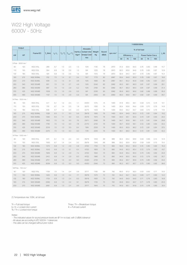
W22 High Voltage 6000V - 50Hz
Y 6000V/50Hz
Output
Frame IEC Tn (Nm) IS / In TS / Tn Tmax / Tn
Inertia J
Kgm2
Allowable
locked rotor
time(s) Cold/
Hot
Weight
Kg
Sound
dB(A)rpm min-1
% of full load
In (A)kW HP Efficiency η Power Factor Cos φ
50 75 100 50 75 100
II Pole - 3000 min-1
90 120 W22 315L 289 6.7 1.5 2.5 1.3 10/5 1135 78 2970 91.3 93.6 94.5 0.76 0.83 0.86 10.7
110 150 W22 315L 354 6.8 1.6 2.6 1.5 8/4 1225 78 2970 92.0 93.9 94.6 0.78 0.85 0.87 12.9
132 180 W22 315L 424 6.8 1.6 2.6 1.6 8/4 1315 78 2970 92.3 94.0 94.7 0.79 0.85 0.87 15.4
160 215 W22 355ML 512 7.5 1.4 3.1 3.4 15/7 1770 80 2987 93.4 94.8 95.3 0.78 0.85 0.87 18.6
200 270 W22 355ML 639 7.5 1.4 3.1 3.8 10/5 1830 80 2987 94.1 95.2 95.6 0.80 0.85 0.87 23.1
250 340 W22 355AB 801 7.0 1.5 2.7 4.9 10/5 2040 83 2982 95.5 96.1 96.3 0.81 0.87 0.89 28.1
280 380 W22 355AB 897 7.5 1.5 2.9 5.2 10/5 2160 83 2982 95.7 96.3 96.5 0.81 0.87 0.89 31.4
315 425 W22 355AB 1009 7.5 1.5 2.9 5.5 8/4 2230 83 2982 95.9 96.5 96.6 0.82 0.88 0.89 35.3
355 480 W22 355AB 1137 7.5 1.5 2.9 5.9 8/4 2300 83 2983 96.0 96.6 96.7 0.82 0.87 0.89 39.7
IV Pole - 1500 min -1
90 120 W22 315L 577 6.7 1.4 2.5 1.7 43/20 1215 74 1490 91.9 93.5 94.1 0.59 0.70 0.76 12.1
110 150 W22 315L 705 6.7 1.4 2.5 1.9 32/15 1330 74 1490 92.4 93.8 94.4 0.59 0.70 0.76 14.8
132 180 W22 315L 846 6.7 1.4 2.5 2.0 32/15 1400 74 1490 93.0 94.2 94.7 0.60 0.70 0.76 17.6
160 215 W22 355ML 1026 6.5 1.1 3.0 5.6 39/18 1560 76 1490 93.4 94.8 95.3 0.72 0.81 0.84 19.2
200 270 W22 355ML 1282 6.5 1.1 3.0 6.5 34/16 1670 76 1490 94.0 95.1 95.5 0.73 0.81 0.84 24.0
250 340 W22 355AB 1602 7.0 1.3 3.0 7.6 23/11 2090 76 1490 94.7 95.8 96.1 0.72 0.81 0.84 29.8
280 380 W22 355AB 1795 7.0 1.3 3.0 7.8 21/10 2150 76 1490 94.7 95.8 96.1 0.72 0.80 0.84 33.4
315 425 W22 355AB 2019 7.0 1.3 3.0 8.4 19/9 2200 76 1490 95.0 95.9 96.2 0.72 0.81 0.84 37.5
355 480 W22 355AB 2275 7.0 1.3 3.0 9.0 17/8 2245 76 1490 95.1 96.0 96.3 0.72 0.81 0.84 42.2
VI Pole - 1000 min -1
90 120 W22 315L 870 6.7 1.4 2.4 3.0 39/18 1200 68 988 92.4 93.4 93.6 0.59 0.69 0.75 12.3
110 150 W22 315L 1063 6.7 1.4 2.4 3.2 39/18 1345 68 988 93.2 93.9 93.9 0.59 0.69 0.75 15.0
132 180 W22 355ML 1273 6.8 1.2 2.9 5.8 47/22 1750 73 990 94.6 95.3 95.3 0.74 0.80 0.82 16.3
160 215 W22 355ML 1543 6.8 1.3 3.1 6.4 47/22 1800 73 990 94.6 95.3 95.4 0.72 0.79 0.82 19.7
200 270 W22 355AB 1929 6.8 1.4 2.9 7.4 47/22 1840 73 990 94.9 95.4 95.5 0.73 0.80 0.82 24.6
250 340 W22 355AB 2412 6.8 1.4 2.9 8.3 47/22 1980 73 990 94.9 95.5 95.5 0.72 0.79 0.82 30.7
280 380 W22 355AB 2701 6.8 1.5 3.0 9.0 43/20 2100 73 990 95.2 95.7 95.6 0.73 0.80 0.82 34.4
315 425 W22 355AB 3039 6.8 1.5 3.0 9.3 43/20 2340 73 990 95.2 95.7 95.7 0.73 0.80 0.82 38.6
VIII Pole - 750 min-1
90 120 W22 315L 1158 7.5 1.4 2.4 3.8 37/17 1180 68 742 89.3 91.3 92.0 0.50 0.63 0.71 13.3
110 150 W22 355ML 1420 6.8 1.3 2.4 7.7 39/18 1570 70 740 94.2 94.7 94.5 0.69 0.77 0.80 14.0
132 180 W22 355ML 1704 6.8 1.3 2.4 8.3 39/18 1650 70 740 94.6 94.9 94.6 0.71 0.78 0.80 16.8
160 215 W22 355AB 2065 6.8 1.3 2.4 9.1 39/18 1725 70 740 94.8 95.0 94.7 0.71 0.78 0.80 20.3
200 270 W22 355AB 2581 6.8 1.3 2.4 9.6 37/17 1840 70 740 94.9 95.1 94.8 0.70 0.78 0.80 25.4
(1) Temperature rise 105K, at full load
Tn = Full load torque Tmax / Tn = Breakdown torque Is / In = Locked rotor current In = Full load current Ts / Tn = Locked rotor torque
Notes: - The indicated values for sound pressure levels are @ 1m no load, with 3 dB(A) tolerance- All values are according to IEC 60034-1 tolerances- This data can be changed without prior notice

www.weg.net
W22 High Voltage 23
W22 High Voltage 4160V - 60Hz
Y 4160V/60Hz
Output
Frame IEC Tn (Nm) IS / In TS / Tn Tmax / TnInertia J
Kgm2
Allowable locked rotor
time Cold/Hot (s)
Weight Kg
Sound dB(A) rpm min-1
% of full load
In (A)kW HP Efficiency η Power Factor Cos j
50 75 100 50 75 100
II Pole - 3000 min-1
90 125 315L 240 7.3 1.4 3.0 1.23 44/20 1000 82 3576 90.2 91.7 92.4 0.72 0.81 0.85 15.9
110 150 315L 294 7.3 1.4 3 1.23 44/20 1050 82 3576 91.7 92.4 93.0 0.72 0.81 0.85 19.3
132 175 315L 353 7.3 1.4 3 1.36 44/20 1070 82 3576 91.7 93.0 93.6 0.72 0.81 0.85 23.0
150 200 315L 401 7.3 1.4 3 1.44 44/20 1080 82 3576 92.4 93.6 94.1 0.72 0.82 0.85 26.0
160 220 315L 427 7.3 1.4 3 1.52 33/15 1100 82 3578 92.9 93.9 94.4 0.73 0.83 0.86 27.4
185 250 315L 494 7.3 1.4 3 1.66 33/15 1200 82 3578 93.2 94.2 94.6 0.74 0.83 0.86 31.6
200 270 315L 533 7.6 1.5 3 1.85 26/12 1300 82 3578 93.6 94.5 94.7 0.73 0.82 0.86 34.1
220 300 315L (1) 587 7.6 1.5 3 1.85 26/12 1300 82 3578 93.6 94.5 94.7 0.73 0.82 0.86 37.5
220 300 355M/L 587 7.5 1.4 3 2.75 44/20 1600 84 3580 94.0 94.4 95.0 0.78 0.85 0.88 36.5
250 340 355M/L 666 7.5 1.4 3 3.07 44/20 1700 84 3580 94.1 94.5 95.1 0.78 0.85 0.88 41.5
260 350 355M/L 693 7.5 1.4 3 3.07 44/20 1700 84 3580 94.1 94.5 95.1 0.78 0.85 0.88 43.1
300 400 355A/B 800 7.8 1.6 2.5 3.86 44/20 1900 89 3582 94.5 95.0 95.4 0.80 0.86 0.88 49.6
315 430 355A/B 840 7.8 1.6 2.5 4.08 44/20 2000 89 3582 94.5 95.4 95.4 0.80 0.86 0.88 52.1
330 450 355A/B 879 7.8 1.6 2.5 4.08 44/20 2000 89 3582 94.5 95.4 95.4 0.80 0.86 0.88 54.6
355 480 355A/B 946 7.8 1.6 2.5 4.44 33/15 2100 89 3582 95.0 95.8 95.8 0.80 0.86 0.88 58.4
370 500 355A/B 990 7.8 1.6 2.5 4.44 33/15 2100 89 3582 95.0 95.8 95.8 0.80 0.86 0.88 60.9
400 550 355A/B 1068 7.8 1.6 2.5 4.87 33/15 2200 89 3582 95.4 95.8 95.8 0.80 0.86 0.88 65.9
440 600 355A/B (1) 1176 8.1 1.7 2.5 4.87 33/15 2200 89 3582 95.4 95.8 96.2 0.78 0.85 0.87 73.0
IV Pole - 1500 min -1
110 150 315L 588 6.6 1.6 2.5 2.99 44/20 880 79 1786 91.2 92.5 93.1 0.69 0.78 0.83 19.8
132 175 315L 706 6.6 1.6 2.5 3.31 44/20 900 79 1786 91.7 93.0 93.6 0.71 0.80 0.84 23.3
150 200 315L 802 6.6 1.6 2.5 3.52 44/20 950 79 1786 92.7 93.8 93.9 0.71 0.80 0.84 26.4
160 220 315L 856 6.6 1.6 2.5 3.71 44/20 1000 79 1786 93.0 94.0 94.1 0.71 0.80 0.84 28.1
185 250 315L 990 6.6 1.6 2.5 4.06 44/20 1100 79 1786 93.2 94.1 94.3 0.71 0.80 0.84 32.4
200 270 315L 1068 6.9 1.7 2.5 4.55 40/18 1200 79 1786 93.5 94.4 94.5 0.71 0.80 0.84 35.0
220 300 315L (1) 1176 7.1 1.8 2.7 4.55 40/18 1200 79 1786 93.8 94.6 94.7 0.71 0.80 0.84 38.4
220 300 355M/L 1176 7.4 2.1 2.7 7.17 55/25 1800 81 1789 93.3 94.4 94.9 0.68 0.78 0.83 38.8
250 340 355M/L 1333 7.6 2.1 2.7 7.72 55/25 1900 81 1789 93.6 94.6 95.1 0.66 0.77 0.82 44.5
260 350 355M/L 1392 7.6 2.1 2.7 7.72 55/25 1900 81 1789 93.6 94.6 95.1 0.66 0.77 0.82 46.3
280 380 355A/B 1490 7.6 2.1 2.7 8.65 55/25 2000 81 1789 94.0 95.0 95.1 0.70 0.80 0.84 48.6
300 400 355A/B 1597 7.6 2.1 2.7 9.19 55/25 2000 81 1789 94.0 95.0 95.1 0.70 0.80 0.84 52.1
315 430 355A/B 1676 7.6 2.1 2.7 9.83 55/25 2100 81 1789 94.2 95.0 95.3 0.70 0.80 0.84 54.6
330 450 355A/B 1764 7.6 2.1 2.7 9.83 55/25 2100 81 1789 94.3 95.0 95.4 0.70 0.80 0.84 57.2
355 480 355A/B 1891 7.6 2.1 2.7 10.8 55/25 2200 81 1789 94.5 95.1 95.5 0.70 0.80 0.84 61.4
370 500 355A/B 1970 7.6 2.1 2.7 10.8 55/25 2200 81 1789 94.7 95.2 95.6 0.70 0.80 0.84 63.9
400 550 355A/B (1) 2136 8.0 2.2 2.8 10.8 44/20 2200 81 1789 94.8 95.4 95.6 0.70 0.80 0.84 69.1
440 600 355A/B (1) 2352 7.6 2.1 2.7 10.8 44/20 2200 81 1788 95.0 95.5 95.7 0.70 0.80 0.84 76.0
VI Pole - 1000 min -1
90 125 315L 726 6.4 1.3 2.1 3.70 35/16 1100 71 1183 92.5 92.7 92.7 0.64 0.75 0.80 16.8
110 150 315L 888 6.4 1.3 2.1 4.40 37/17 1200 71 1182 92.8 92.9 92.9 0.67 0.77 0.81 20.3
132 175 315L 1068 6.4 1.3 2.1 4.80 31/14 1300 71 1182 93.0 93.2 93.3 0.67 0.77 0.81 24.2
150 200 315L 1215 6.6 1.3 2.1 4.80 31/14 1300 71 1182 93.2 93.6 93.6 0.66 0.77 0.81 27.5
160 220 315L 1294 6.6 1.3 2.2 5.20 26/12 1400 71 1182 93.5 93.8 93.8 0.65 0.77 0.81 29.2
185 250 315L (1) 1490 6.8 1.3 2.2 5.20 26/12 1400 71 1182 93.7 93.9 93.9 0.64 0.76 0.80 34.2
185 250 355M/L 1480 7.0 1.7 2.3 10.4 42/19 1700 77 1191 92.9 94.0 94.3 0.60 0.71 0.77 35.4
200 270 355M/L 1607 7.0 1.7 2.3 11.1 42/19 1800 77 1191 93.0 94.1 94.4 0.60 0.71 0.77 38.2
220 300 355M/L 1764 7.2 1.7 2.3 11.9 42/19 1900 77 1191 93.2 94.2 94.5 0.60 0.71 0.77 42.0
250 340 355A/B 1999 7.0 1.7 2.3 12.7 33/15 2000 77 1191 93.7 94.6 94.6 0.60 0.71 0.77 47.6
260 350 355A/B 2087 7.0 1.7 2.3 12.7 33/15 2000 77 1191 93.7 94.6 94.6 0.60 0.71 0.77 49.5
280 380 355A/B 2244 7.0 1.7 2.3 13.0 40/18 2100 77 1191 93.9 94.8 94.8 0.60 0.71 0.77 53.2
300 400 355A/B 2401 7.2 1.8 2.4 13.8 40/18 2200 77 1191 94.0 94.9 95.0 0.59 0.71 0.77 56.9
315 430 355A/B 2528 7.0 1.6 2.2 15.0 26/12 2300 77 1190 94.2 95.0 95.1 0.60 0.72 0.78 58.9
330 450 355A/B 2646 6.8 1.5 2.1 15.0 26/12 2300 77 1190 94.3 95.0 95.1 0.62 0.73 0.78 61.7
355 480 355A/B (1) 2852 6.8 1.5 2.1 15.4 26/12 2400 77 1190 94.3 95.0 95.1 0.61 0.72 0.78 66.4
370 500 355A/B (1) 2969 6.8 1.5 2.1 15.4 26/12 2400 77 1190 94.3 95.0 95.1 0.61 0.72 0.78 69.2
VIII Pole - 750 min-1
90 125 315L 963 6.3 1.8 2.1 4.80 33/15 1200 71 892 91.8 92.9 93.0 0.51 0.63 0.70 19.2
110 150 315L 1176 6.5 2 2.5 5.40 31/14 1300 71 892 92.2 93.0 93.1 0.51 0.63 0.70 23.4
132 175 315L 1411 6.3 1.8 2.2 5.80 24/11 1400 71 891 92.5 93.4 93.3 0.49 0.62 0.69 28.5
150 200 315L (1) 1607 6.3 1.8 2.2 5.80 24/11 1400 71 891 92.6 93.4 93.5 0.49 0.62 0.69 32.3
150 200 355M/L 1607 6.6 1.8 2.4 11.8 46/21 1700 75 893 92.6 93.7 94.0 0.53 0.65 0.73 30.3
160 220 355M/L 1715 6.6 1.8 2.4 12.6 46/21 1800 75 893 92.8 93.9 94.1 0.53 0.65 0.73 32.3
185 250 355M/L 1980 6.7 1.8 2.4 12.6 46/21 1800 75 893 93.0 94.0 94.2 0.53 0.65 0.73 37.3
200 270 355A/B 2136 6.6 1.8 2.4 13.0 40/18 2000 75 893 93.3 94.2 94.4 0.53 0.65 0.73 40.3
220 300 355A/B 2352 6.6 1.8 2.7 13.7 40/18 2100 75 893 93.6 94.4 94.5 0.53 0.65 0.73 44.3
250 340 355A/B 2675 6.8 2 2.9 15.0 37/17 2200 75 893 94.2 94.8 94.9 0.52 0.65 0.72 50.8
260 350 355A/B 2783 6.8 2 2.9 15.0 37/17 2200 75 893 94.2 94.8 94.9 0.52 0.65 0.72 52.8
280 380 355A/B (1) 2999 6.5 1.7 2.5 15.0 26/12 2300 75 891 94.3 94.9 95.0 0.54 0.66 0.73 56.0
300 400 355A/B (1) 3214 6.2 1.7 2.5 15.0 26/12 2300 75 891 94.4 94.9 95.0 0.55 0.67 0.74 59.2
(1) Temperature rise 105K, at full load
Tn = Full load torque Tmax / Tn = Breakdown torque Is / In = Locked rotor current In = Full load current Ts / Tn = Locked rotor torque
Notes: - The indicated values for sound pressure levels are @ 1m no load, with 3 dB(A) tolerance- All values are according to IEC 60034-1 tolerances- This data can be changed without prior notice

www.weg.net
W22 High Voltage24
15. Mechanical Data
W22 High Voltage B3T
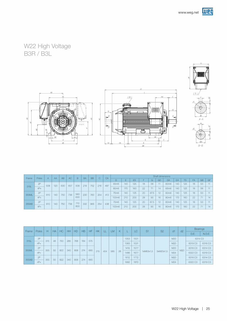
Frame Poles A AA AB AC B BA BB C CAShaft dimensions
D E ES F G GD DA EA TS FA GB GF
315L2P
508 120 630 657 508 219 752 216 49765m6 140 125 18 58 11 60m6 140 125 18 53 11
4P+ 80m6 170 160 22 71 14 65m6 140 125 18 58 11
355ML2P
610 140 750 736 560630
230 760 254 41375m6 140 125 20 67.5 12 60m6 140 125 18 53 11
4P+ 100m6 210 200 28 90 16 80m6 170 160 22 71 14
355AB2P
610 140 750 736 710800
332 965 254 43875m6 140 125 20 67.5 12 60m6 140 125 18 53 11
4P+ 100m6 210 200 28 90 16 80m6 170 160 22 71 14
Frame Poles H HA HC HD HH HK LL LM K L LC S1 S2 d1 d2Bearings
D.E. N.D.E.
315L2P
315 48 750 897 285
215 404 585 28
1353 1501
1xM63x1,5 3xM20x1,5
M20
M20
6314 C3
4P+ 1383 1531 M20 6319 C3 6316 C3
355ML2P
355 50 822 987 3401416 1577 M20 6316 C3 6314 C3
4P+ 1486 1677 M24 6322 C3 6319 C3
355AB2P
355 50 822 987 3401612 1772 M20 6316 C3 6314 C3
4P+ 1682 1872 M24 6322 C3 6319 C3
www.weg.net
W22 High Voltage 25
Frame Poles A AA AB AC B BA BB C CAShaft dimensions
D E ES F G GD DA EA TS FA GB GF
315L2P
508 120 630 657 508 219 752 216 49765m6 140 125 18 58 11 60m6 140 125 18 53 11
4P+ 80m6 170 160 22 71 14 65m6 140 125 18 58 11
355ML2P
610 140 750 736 560630
230 760 254 41375m6 140 125 20 67.5 12 60m6 140 125 18 53 11
4P+ 100m6 210 200 28 90 16 80m6 170 160 22 71 14
355AB2P
610 140 750 736 710800
332 965 254 43875m6 140 125 20 67.5 12 60m6 140 125 18 53 11
4P+ 100m6 210 200 28 90 16 80m6 170 160 22 71 14
W22 High Voltage B3R / B3L
Frame Poles H HA HC HH HD’
HB HF HK LL LM K L LC S1 S2 d1 d2Bearings
D.E. N.D.E.
315L2P
315 48 750 285 768 184 575
215 404 585 28
1353 1501
1xM63x1,5 3xM20x1,5
M20
M20
6314 C3
4P+ 1383 1531 M20 6319 C3 6316 C3
355ML2P
355 50 822 340 858 274 6651416 1577 M20 6316 C3 6314 C3
4P+ 1486 1677 M24 6322 C3 6319 C3
355AB2P
355 50 822 340 858 274 6651612 1772 M20 6316 C3 6314 C3
4P+ 1682 1872 M24 6322 C3 6319 C3
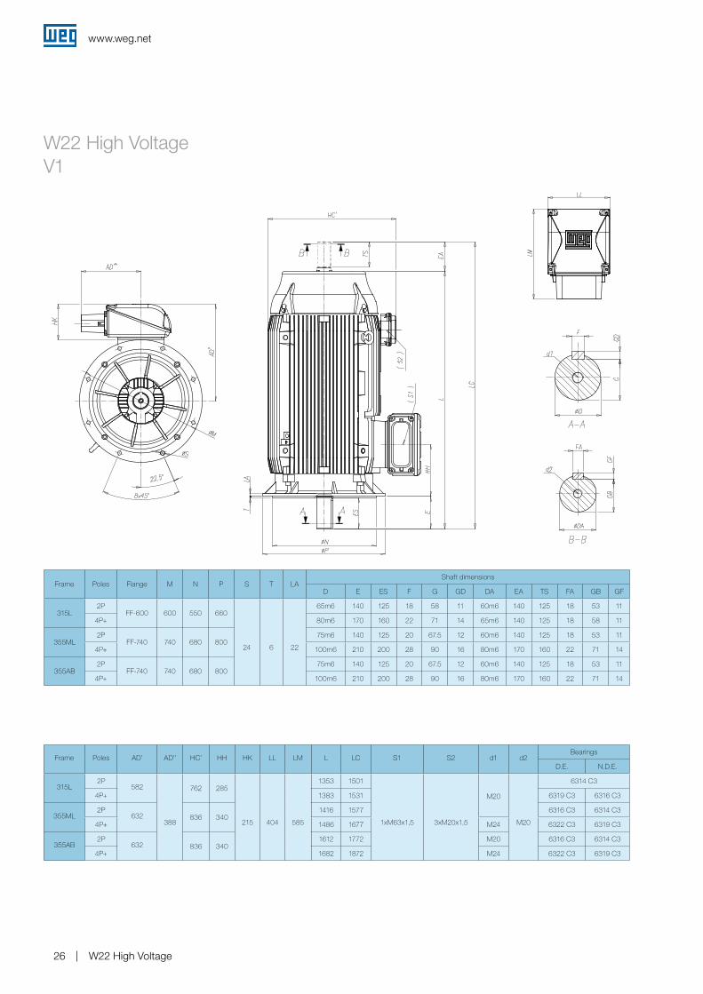
www.weg.net
W22 High Voltage26
W22 High Voltage V1
Frame Poles Flange M N P S T LAShaft dimensions
D E ES F G GD DA EA TS FA GB GF
315L2P
FF-600 600 550 660
24 6 22
65m6 140 125 18 58 11 60m6 140 125 18 53 11
4P+ 80m6 170 160 22 71 14 65m6 140 125 18 58 11
355ML2P
FF-740 740 680 80075m6 140 125 20 67.5 12 60m6 140 125 18 53 11
4P+ 100m6 210 200 28 90 16 80m6 170 160 22 71 14
355AB2P
FF-740 740 680 80075m6 140 125 20 67.5 12 60m6 140 125 18 53 11
4P+ 100m6 210 200 28 90 16 80m6 170 160 22 71 14
Frame Poles AD’ AD’’ HC’ HH HK LL LM L LC S1 S2 d1 d2Bearings
D.E. N.D.E.
315L2P
582
388
762 285
215 404 585
1353 1501
1xM63x1,5 3xM20x1,5
M20
M20
6314 C3
4P+ 1383 1531 6319 C3 6316 C3
355ML2P
632 836 3401416 1577 6316 C3 6314 C3
4P+ 1486 1677 M24 6322 C3 6319 C3
355AB2P
632 836 3401612 1772 M20 6316 C3 6314 C3
4P+ 1682 1872 M24 6322 C3 6319 C3

www.weg.net
W22 High Voltage 27
16. Terminal box drawings
Terminal Box
Auxiliary Terminal Box
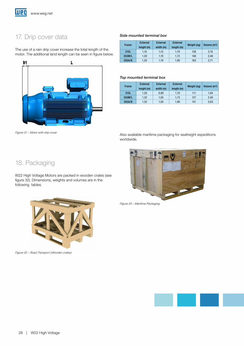
www.weg.net
W22 High Voltage28
17. Drip cover data
The use of a rain drip cover increase the total length of the motor. The additional land length can be seen in figure below.
Figure 31 – Motor with drip cover
18. Packaging
W22 High Voltage Motors are packed in wooden crates (see figure 32). Dimensions, weights and volumes are in the following tables.
Figure 32 – Road Transport (Wooden crates)
Side mounted terminal box
FrameExternal
height (m)
External
width (m)
External
length (m)Weight (kg) Volume (m³)
315L 1,10 1,12 1,70 138 2,10
355M/L 1,20 1,19 1,72 146 2,46
355A/B 1,20 1,19 1,90 163 2,71
Top mounted terminal box
FrameExternal
height (m)
External
width (m)
External
length (m)Weight (kg) Volume (m³)
315L 1,20 0,90 1,70 111 1,84
355M/L 1,32 1,05 1,73 127 2,40
355A/B 1,32 1,05 1,90 141 2,63
Also available maritime packaging for seafreight expeditions worldwide.
Figure 33 – Maritime Packaging

www.weg.net
W22 High Voltage 29
19. Inquiry and Order Check List
This check list refers the essential information to be transmitted with inquiry/order. The maximum details provided will help both WEG/CUSTOMER to select/supply the correct motor to the application.
Motor Standards:
Basic Design:
Rating: [kW]
Frequency: [Hz]
Poles/Speed:
Insulation class: (F) / (H)
Motor temp. rise: [K]
Design amb. temp. (40ºC)
Mounting form IM:
Balancing grade: A B
Rotation view from D.E. side: CW CCW Both
Supply terminal box arrangement:
2nd power term. box: Neutral point
Other
Terminal box adapter
Auxiliaries & Accessories:
Protection on windings (if different from standard):
Thermistor: (PTC / NTC)
PT100: - Nº phase:
- Nº wires:
Auxiliary term. box:
Protection on bearings (if different from standard):
Thermistor: (PTC / NTC)
PT100: - Nº/bearing:
- Nº wires:
Auxiliary term. box: Same termina box of windings protections
2nd aux terminal box
2 separate terminal boxes (1/endshield)
Space heaters (if different from standard):
Voltage: [V]
Individual terminal box:
Cable Entry Details: Cable entry direction view from D.E. side: RHS LHS Nº of cable entries:
Supply terminal box:
Auxiliary terminal box(es):
Glands thread size(s):
Supply/Instrumentation cable information:
Nº cables:
Type of cables: (armoured / non armoured)
Cables diameter: - External:
- Without armour:
Cable gland supplied with motor: (WEG can supply glands
acc. to info about cables):
Cable gland(s) size(s):
Cable gland(s) type(s):
Starting:
Starting method:
DOL:
VSD: Speed range:
Soft starter:
Star / Delta:
Other:
Duty (if different from S1):
Service factor (if different from 1,0):
Nº starts/hour: g Cold:
g Hot:
Coupling:
Direct
Pulley/Belt:
Pulleys diam. (dp/Dp):
Pulleys width:
Distance between centers (DC):
Nº/Type belts.:
Gearbox.:
Gearbox ratio:
Ambient Conditions:
Ambient temperature: (ºC)
Min. temperature: (ºC)
Max. temperature: (ºC)
Humidity: (%)
Altitude: (m.a.s.l.)
Environment: (Saline; Alcaline; Marine; Petrochemical; Sulphur
(H2S); Other...)
Paint Scheme (if different from standard):
202E
202P
211E
211P
212E
212P
213E
Color (RAL):
Driven Machine Data:
Driven machine type: (centrífugal fan/pump; reciprocating pump/compressor; blower; mills; cranes; conveyor belt; ....)
Absorved power: [kW]
Driven machine torque curve: (Quadratic; constant; other...)
Starting torque: [Nm]
Rated torque: [Nm]
Load inertia: (J or PD2)
19.1 BASIC MOTOR DATA AND FEATURES 19.2 SITE & WORKING CONDITIONS

www.weg.net
W22 High Voltage30
Notes

Notes

www.weg.net
W22 High Voltage32
Notes

Notes

125.
25 R
ev.0
2
0
1/20
11
WEG Worldwide Operations
ARGENTINAWEG EQUIPAMIENTOS ELECTRICOS S.A.(Headquarters San Francisco-Cordoba)Sgo. Pampiglione 4849Parque Industrial San Francisco2400 - San FranciscoPhone(s): +54 (3564) 421484Fax: +54 (3564) [email protected]/ar
AUSTRALIAWEG AUSTRALIA PTY. LTD.3 Dalmore DriveCarribean Park Industrial EstateScoresby VIC 3179 - MelbournePhone(s): 61 (3) 9765 4600Fax: 61 (3) 9753 [email protected]/au
BELGIUM WEG BENELUX S.A.Rue de l’Industrie 30 D, 1400 NivellesPhone(s): + 32 (67) 88-8420Fax: + 32 (67) 84-1748 [email protected]/be
BRAZIL WEG EQUIPAMENTOS ELÉCTRICOS, S.A.International DivisionAv. Prefeito Waldemar Grubba, 300089256-900 – Jaraguá do Sul – SCPhone(s): 55 (47) 3276-4002Fax: 55 (47) [email protected]/be
CHILEWEG CHILE S.A.Los Canteros 8600 La Reina - SantiagoPhone(s): (56-2) 784 8900Fax: (56-2) 784 [email protected]/cl
CHINAWEG (NANTONG) ELECTRIC MO-TOR MANUFACTURING CO., LTD.No. 128# - Xinkai South Road,Nantong Economic & Technical Development Zone, Nantong, Jiangsu Province. Phone(s): (86) 0513-85989333Fax: (86) [email protected]/cn
COLOMBIAWEG COLOMBIA LTDACalle 46A N82 - 54Portería II - Bodega 7 - San Cayetano II - BogotáPhone(s): (57 1) 416 0166Fax: (57 1) 416 [email protected]/co
FRANCEWEG FRANCE SASZI de Chenes – Le Loup13 Rue du Morellon – BP 73838297 Saint Quentin FallavierPhone(s): +33 (0) 4 74 99 11 35Fax: +33 (0) 4 74 99 11 [email protected]/fr
GERMANYWEG GERMANY GmbHIndustriegebiet Türnich 3Geigerstraße 750169 Kerpen-TürnichPhone(s): +49 (0)2237/9291-0Fax: +49 (0)2237/[email protected]/de
INDIAWEG ELECTRIC (INDIA) Pvt. Ltd.#38, Ground Floor, 1st Main Road, Lower Palace Orchards,Bangalore – 560 003Phone(s): +91-80-4128 2007 +91-80-4128 2006 Fax: +91-80-2336 7624 [email protected]/in
ITALYWEG ITALIA S.R.L.V.le Brianza 20 - 20092 - Cinisello Balsamo - MilanoPhone(s): (39) 02 6129-3535Fax: (39) 02 [email protected]/it
JAPANWEG ELECTRIC MOTORSJAPAN CO., LTD.Yokohama Sky Building 20F, 2-19-12 Takashima, Nishi-ku, Yokohama City,Kanagawa, Japan 220-001Phone: (81) 45 440 [email protected]/jp
MEXICOWEG MEXICO, S.A. DE C.V.Carretera Jorobas-Tula Km. 3.5, Manzana 5, Lote 1 Fraccionamiento Parque Industrial - Huehuetoca, Estado de México - C.P. 54680Phone(s): + 52 (55) 5321 4275Fax: + 52 (55) 5321 [email protected]/mx
NETHERLANDSWEG NETHERLANDS Sales Office of WEG Benelux S.A.Hanzepoort 23C 7575 DB OldenzaalPhone(s): +31 (0) 541-571080Fax: +31 (0) [email protected]/nl
PORTUGALWEGEURO - INDÚSTRIA ELÉC-TRICA, S.A.Rua Eng. Frederico UlrichApartado 6074 4476-908 - MaiaPhone(s): +351 229 477 705Fax: +351 229 477 [email protected]/pt
RUSSIAWEG RUSSIA Pochainskaya Str. 17 Nizhny Novgorod 603001 - Russia Phone(s): +7-831-2780425 Fax: [email protected] www.weg.net/ru
SPAINWEG IBERIA S.L. Avenida de la Industria,2528823 Coslada - MadridPhone(s) : (34) 916 553 008Fax : (34) 916 553 [email protected]/es
SINGAPOREWEG SINGAPORE PTE LTD159, Kampong Ampat, #06-02A KA PLACE. Singapore 368328.Phone(s): +65 6858 9081Fax: +65 6858 [email protected]/sg
SWEDENWEG SCANDINAVIA ABBox 10196Verkstadgatan 9434 22 KungsbackaPhone(s): (46) 300 73400Fax: (46) 300 [email protected]/se
UKWEG ELECTRIC MOTORS (U.K.) LTD.28/29 Walkers RoadManorside Industrial EstateNorth Moons Moat - RedditchWorcestershire B98 9HEPhone(s): 44 (0)1527 596-748Fax: 44 (0)1527 [email protected]/uk
UNITED ARAB EMIRATESWEG MIDDLE EAST FZEJAFZA – JEBEL ALI FREE ZONETower 18, 19th Floor, Office LB 18 1905P.O. Box 262508 - DubaiPhone: +971 (4) 8130800 Fax: +971 (4) [email protected]/ae
USAWEG ELECTRIC CORP. 6655 Sugarloaf Parkway, Duluth, GA 30097 Phone(s): 1-678-249-2000Fax: [email protected] www.weg.net/us
VENEZUELAWEG INDUSTRIAS VENEZUELA C.A.Avenida 138-AEdificio Torre Banco Occidental de Descuento, Piso 6 Oficina 6-12Urbanizacion San Jose de TarbesZona Postal 2001Valencia, Edo. CaraboboPhone(s): (58) 241 8210582 (58) 241 8210799 (58) 241 8211457Fax: (58) 241 [email protected]/ve
WEGeuro - Industria Eléctrica, S.A.Rua Engº Frederico Ulrich, Sector Y4476-908 MAIAPORTUGAL Phone: +351 229 477 700 Fax: +351 229 477 [email protected]/pt