motorola bts updated
DESCRIPTION
Motorola BTS UpdatedTRANSCRIPT

1
Motorola BTS

Objective
To be able to understand the functional areas of Motorola Horizon I&II macro cabinet, description of their digital modules and cabinet RF components
Introduction & description of VSWR, RF feeder cables and antennas
To understand BTS Command Interface with Procom plusTX Calibration of single/double density DRIs

3
Table of Contents
• Introduction to BSS
• BTS Basics
• HMAC II & I features
• VSWR, Antenna Tilting
• DRIs TX/RX Calibration
• Command interface
• Tools Required

Introduction to BSS

ACEIR
BTS
OMC
MSC
VLR
HLR
BSC
BTS
BTS
BTS
BTS
BSC
BSS - Base StationSubsystem
NSS - Network Subsystem
NMS - Network Management SystemMS
AbisAir A
IWF
SC
PSPDN
PSTNISDN
Transcoder
GSM Architecture

Transcoder function
Although transcoder is considered to be a part of BSS, it is most often located closer to MSC. Basic function is to reduce the data rate of the signals from MSC

BTS Site
A base transceiver station (BTS) or cell site is a piece of equipment that facilitates wireless communication between user equipment (UE) and a network.
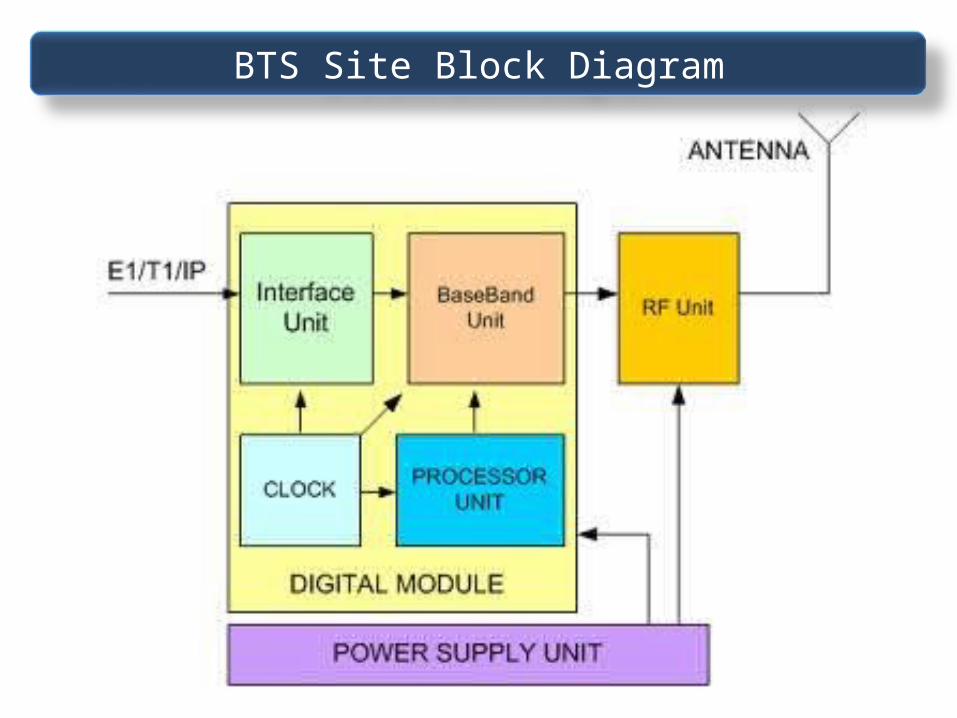
BTS Site Block Diagram

• Main Processor Alarms collection and management, transceivers management, software download, controlling expansions and interface panels
• Clock source unitDeliver a stable clocking source to all digital equipments
• Interface Panel Translate the source data (Abis) to BTS Format digital data
• Base Band Unitthe digital data is processed following the GSM standard, this unit creates a data which ready to be feed to RF Unit
• Power Supply Unitproduces a power for whole equipments in the BTS
• RF Unitconverts the digital signal to Radio Frequency Signal (air interface signal) following the GSM Standard. This signal type is still as an electrical signal.
• Antenna UnitAntenna as a traditional unit, have a function to convert electrical signal to electromagnetic signal.
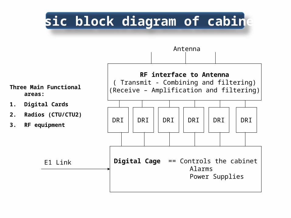
Three Main Functional areas:
1. Digital Cards
2. Radios (CTU/CTU2)
3. RF equipment
RF interface to Antenna( Transmit - Combining and filtering)
(Receive – Amplification and filtering)
DRI DRI DRI DRI DRI DRI
E1 Link Digital Cage == Controls the cabinet Alarms Power Supplies
Antenna
Basic block diagram of cabinet

Site Controller (HIISC)
CTU2
Cooling Fans
Power Supply Units (PSU)
Circuit Breaker
Card (CBC)
Alarm Board
HMACII Front View
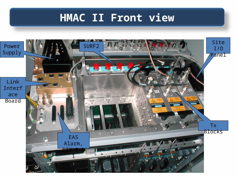
Site I/O Panel
Tx Blocks
Link Interface
Board
SURF2Power Supply
EAS Alarm, PIX 0 & 1
HMAC II Front view

Maximum 4x PSU per cabinet – One for RedundancyDepends on the number of Radios fitted.
The Cabinet can support the three types of power supply
• +27V (negative earth)• -48V (positive earth)• Nominal 120/240V AC
Power Supply Unit
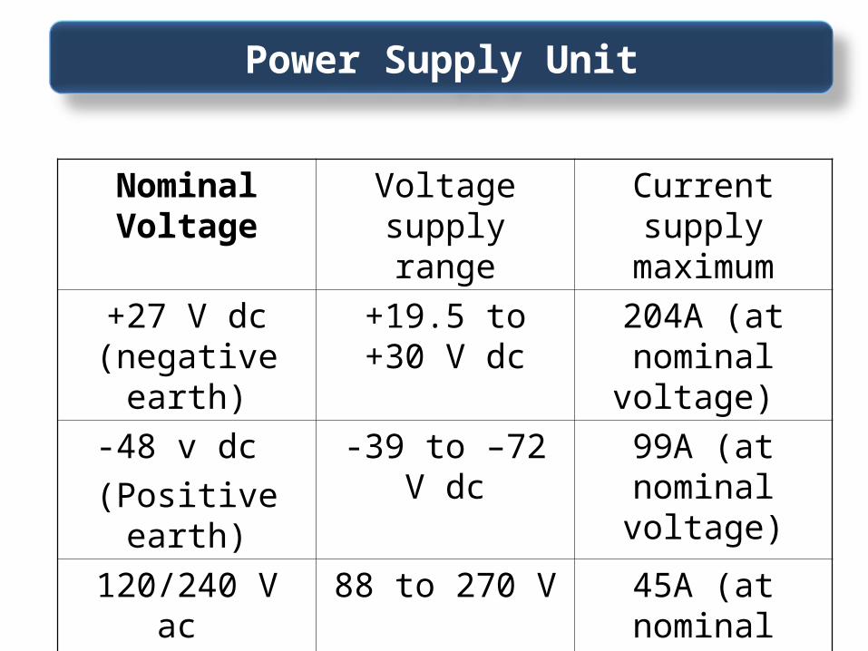
Nominal Voltage
Voltage supply range
Current supply maximum
+27 V dc (negative earth)
+19.5 to +30 V dc
204A (at nominal voltage)
-48 v dc
(Positive earth)
-39 to –72 V dc 99A (at nominal voltage)
120/240 V ac
(50 to 60 Hz)
88 to 270 V 45A (at nominal voltage)
Power Supply Unit
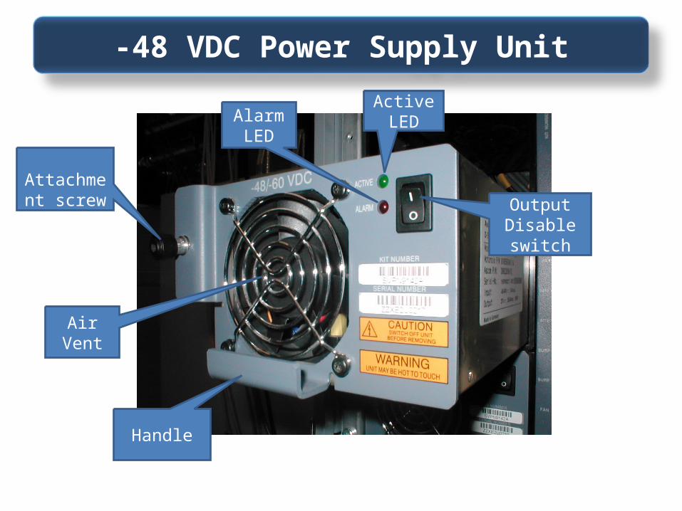
Air Vent
Alarm LED
Output Disable switch
Active LED
Attachment
screw
Handle
-48 VDC Power Supply Unit

All three unit types support the same PSU Alarms:
• O/P over/under voltage.• I/P under voltage.• Over temperature.• Internal Fan failure.
PSU Alarms

6x CCB for CTU2
2x Push Button HIISC
2x Push Button SURF2
1x Tx RF Blocks
1x FAN trays
Circuit Breaker Card (CBC)
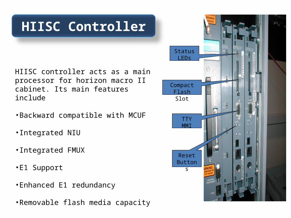
Status LEDs
Compact Flash Slot
TTY MMI
Reset Buttons
HIISC Controller
HIISC controller acts as a main processor for horizon macro II cabinet. Its main features include
•Backward compatible with MCUF
•Integrated NIU
•Integrated FMUX
•E1 Support
•Enhanced E1 redundancy
•Removable flash media capacity

XMUX in slot 0
Expanding a BTS
Fibre connections
IN/OUT
XMUX Location
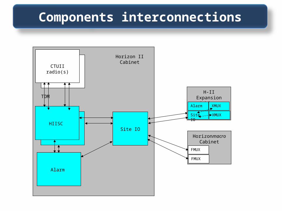
Horizon IICabinet
H-II Radio
NBSCHIISC
Alarm
CTUII radio(s)
TDM
Site IO
H-II ExpansionCabinet
Site IO
XMUX
XMUX
HorizonmacroCabinet
FMUX
FMUX
Alarm
Components interconnections
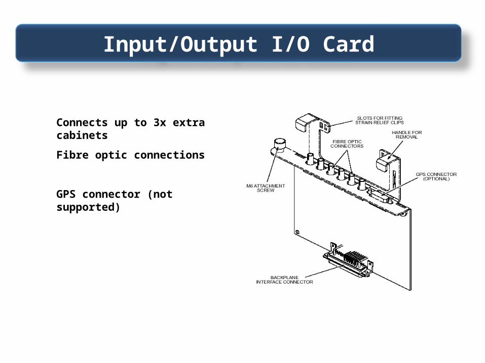
Site Expansion Board
Connects up to 3x extra cabinets
Fibre optic connections
GPS connector (not supported)
Input/Output I/O Card

Horizon IImacro (6xCTU2)
XMUX
Horizon IImacro (6xCTU2)
E1
Two Horizon II macro’s expanded.
Horizon IImacro (6xCTU2)
XMUX
Horizon IImacro (6xCTU2)
Horizonmacro (6 x CTU)
FMUX
E1
Horizon II macro, expanded to a Horizon II macro and a Horizonmacro.
Horizonmacro controlling a Horizon II macro and another Horizonmacro.
Expansion configurations

• Operating range -5 C to +45 C
• Three Internal FAN units – speed controlled
• 3x Cabinet Temperature Sensors – » 1x (70 C) for cabinet alarm» 2x (85 C) to shutdown the cabinet, reset at 55 C.
Cabinet Temperature Control

Mains
Door 1
LVD
Fan 0
Fan 1 & 2
ALL LEDs are GREEN when the equipment is OKRED when equipment is faulty
Alarm Board
Provides External alarm monitoring from the cabinet via the backplane
• Cabinet Power Supply Units
• Environmental controlled devices(over temperature
• Customer defined alarms(EAS)
• Antenna VSWR monitoring(via TX blocks)

Compact Transceiver Unit ( CTU2)
Single Density Mode – High Power 63W (48dbm) 900MHz
50W (47dbm) 1800MHz
Normal Power 20W (43dbm) 900MHz
16W (42dbm) 1800MHz
Double Density Mode –Normal Power 20W (43dbm) 900MHz
16W (42dbm) 1800MHZ

TRANSMIT RF OUT
TTY INTERFACE
Radio Status LED
Tx Status B LED
Tx Status A LED
The CTU2 transceiver has the ability to support two logical carriers within a single transceiver unit. A CTU2 is backward compatible with HMAC I through software control.
Compact Transceiver Unit 2 (CTU2)

RF Equipment
RF Equipment
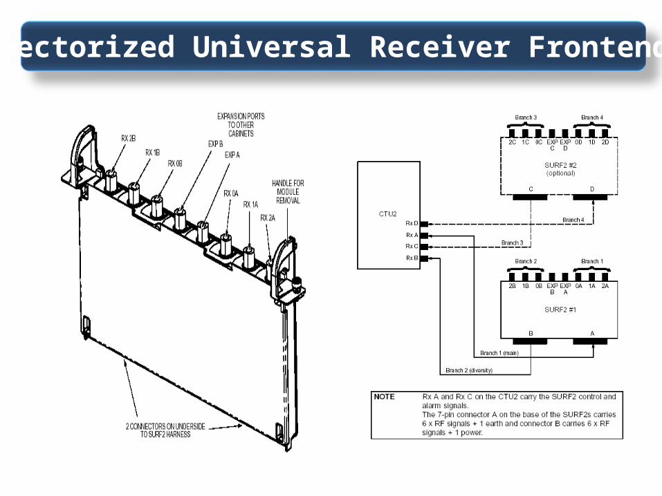
Sectorized Universal Receiver Frontend
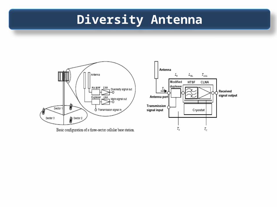
Diversity Antenna
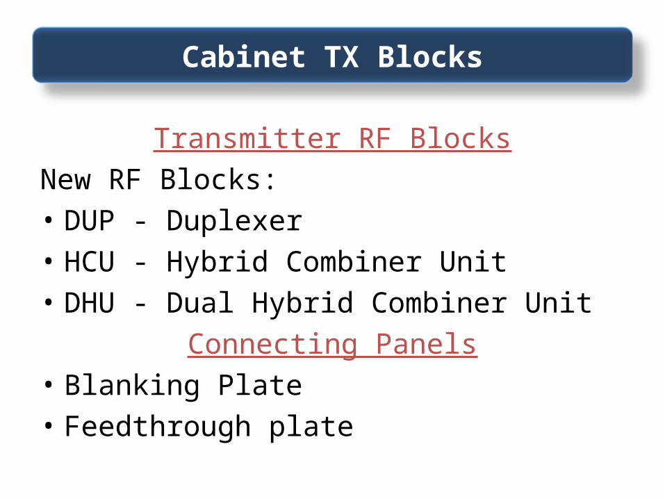
Transmitter RF BlocksNew RF Blocks:• DUP - Duplexer• HCU - Hybrid Combiner Unit• DHU - Dual Hybrid Combiner Unit
Connecting Panels• Blanking Plate• Feedthrough plate
Cabinet TX Blocks

Feedthrough and Connecting
Plates
Duplexer
RX Connector
SURF

Duplexer Feedthrough Plate
Blanking Plate
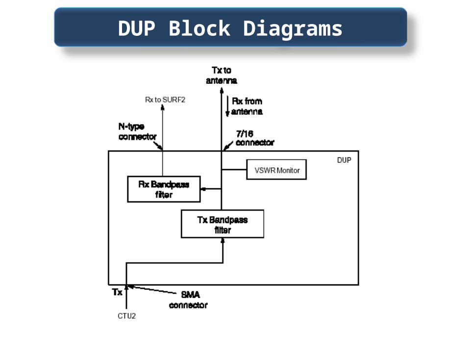
DUP Block Diagrams

DHU & HCU Block Diagrams

CTU2
Signal
Tx Block
Rx Filter
Tx Filter
VSWRMonitor
AlarmBoard
AntennaTo SURF
Tx
• The Antenna VSWR monitoring function is used to detect faults in antennas or antenna path connections.
VSWR Monitoring

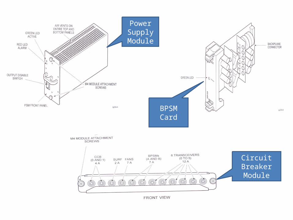
HMAC I
HMAC I cabinet comprises of three main parts
•Power Supply Module•Circuit Breaker Module•Binary PSM

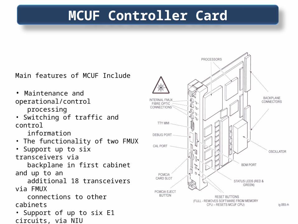
Main features of MCUF Include
• Maintenance and operational/control processing• Switching of traffic and control information• The functionality of two FMUX• Support up to six transceivers via backplane in first cabinet and up to an additional 18 transceivers via FMUX connections to other cabinets• Support of up to six E1 circuits, via NIU modules
MCUF Controller Card
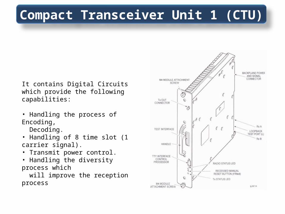
Compact Transceiver Unit 1 (CTU)
It contains Digital Circuits which provide the following capabilities:
• Handling the process of Encoding, Decoding.• Handling of 8 time slot (1 carrier signal).• Transmit power control. • Handling the diversity process which will improve the reception process
Power Supply Module
BPSM Card
Circuit Breaker Module

Function Horizon II macro component Horizonmacro I equivalent
Input power conversion units (max fitted) PSU
(4)
PSM
(3)
Power to transceivers and signal routeing Backplane BPSM and backplane
Transceivers
(max fitted)
CTU2
(6)
CTU
(6)
Main processor module
(Max fitted)
HIISC
(2)
MCUF
(2)
Processor module connection to transceivers
in another cabinet
Internal XMUX in HIISC (1) and
separate site expansion boards
(1 or 2)
Internal FMUX in
MCUF (2) or
external FMUX (2)
Slave cabinet multiplexer XMUX FMUX
Rx components
(Max fitted)
SURF2
(2)
SURF
(1)
Transceiver to Rx components SURF2 harness SURF harness
TX blocks
(Max fitted internally)
DUP, HCU and DHU
(6)
DCF, TDF, DDF and HCU
(3)
DC power supply for digital modules
(Max fitted)
Integrated in HIISC supplied via
backplane
BPSM
(2)
Equipment protection/isolation CBC CBM
Links to terrestrial network
(Max fitted)
Internal NIU in HIISC NIU
(4)
Alarm Handling Alarm Module *** Alarm Module
E1/T1 links CIM/T43 or BIM/BIB CIM/T43 or BIM/BIB
HMAC II vs HMAC I

Voltage standing wave ratio (VSWR) is the ratio of the maximum voltage amplitude of a reflected wave ( ) to the minimum voltage amplitude ( ), in an electrical transmission line.Reflections occur as a result of discontinuities, such as an imperfection in an otherwise uniform transmission line, or when a transmission line is terminated with other than its characteristic impedance.
ρ = | | (Reflection Coefficient)
Voltage Standing Wave Ratio (VSWR)

DBC(DUAL BAND CMBINERS) ( MAX 1.09)
VSWR Standards

BTSBTS
DBCDBCArrestorsArrestors
Antenna Jumper
Antenna1.04
1.091.06
1.08
1.16
GSM Measure Match = 1.35DCS Measure Match = 1.45

1
1.0
1.1
1.2
1.3
1.4
0 5 10 15 20 25 30 35 40 45 50
Limit: 1.400
Distance To FaultDistance: 0 meters - 50 meters (Full Cal)
PSH.0014.RMC.DCS.SEC.B1 9/11/2008 5:11:00 PM
M1:( 32.81, 1.18)
VS
WR
Distance (meters)
1
1.0
1.1
1.2
1.3
1725 1750 1775 1800 1825 1850 1875
VSWRFrequency: 1710 MHz - 1880 MHz (Full Cal)
PSH.0014.RMC.DCS.SEC.A 9/11/2008 5:23:00 PM
M1:(1879.28, 1.35)
VS
WR
Frequency (MHz)
Fault Location
Measure Match

50 ohm RF Communication feeder cable Advantages:
1. Excellent Electrical performances: 80% super-high degree foaming polyethylene insulation of features with low attenuation and stability in case of temperature variation. The extra-precisely corrugated copper tube outer conductor, characteristic of low VSWR makes the cable a choice even in high-frequency applications.
2. Simple use and complete range: The light, flexible and easily-bending thin-wall corrugated copper conductor offers convenience for terminal work.
3. Ease of maintenance: The special structure presents premises for effective moisture-proofing, thus assuring performances stability in terms of long period.
RF cable Advantages

All outdoor antenna feeder runs should be grounded at theirlowest point just prior to entering the base station or radioenclosure. Depending on the height of the tower run, additionalground points may be required (see table below).
RF Cable Grounding Locations

Grounding Kit
Grounding Kit
Bundled grounding
Individual grounding

Site Master
Insulation cutter
Warding FilesKnife
Open End Spanners Closed End Spanners
Adjustable SpannersCable Cutter
Tools Required (VSWR)

EMR
Antennas

Antenna
A dipole antenna is an antenna that can be made by a simple wire, with a center-fed driven element for transmitting or receiving radio frequency energy.
An antenna (or aerial) is a transducer that transmits or receives electromagnetic waves. In other words, antennas convert electromagnetic radiation into electrical current, or vice versa. Physically, an antenna is an arrangement of one or more conductors, usually called elements
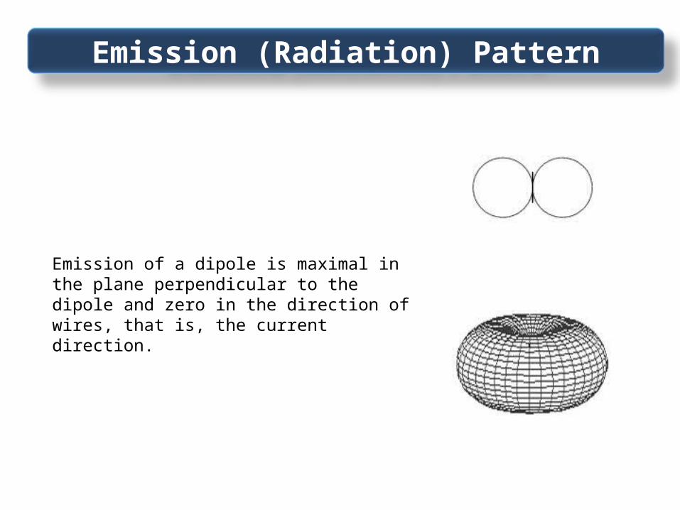
Emission (Radiation) Pattern
Emission of a dipole is maximal in the plane perpendicular to the dipole and zero in the direction of wires, that is, the current direction.

Electromagnetic Radiation (EMR)
EMR comprises electric and magnetic field components, which oscillate in phase perpendicular to each other and perpendicular to the direction of energy propagation.
The polarization of anelectromagnetic wave is defined as theorientation of the electric field vector

Beam Tilting
Beam tilt is used in radio to aim the main lobe of the vertical plane radiation pattern of an antenna below (or above) the horizontal plane.
Simplest way is mechanical tilting, but it creates a back lobe
More common is the electrical tilting, where the phasing between antenna elements is tweaked to make the signal go down (usually) in all directions
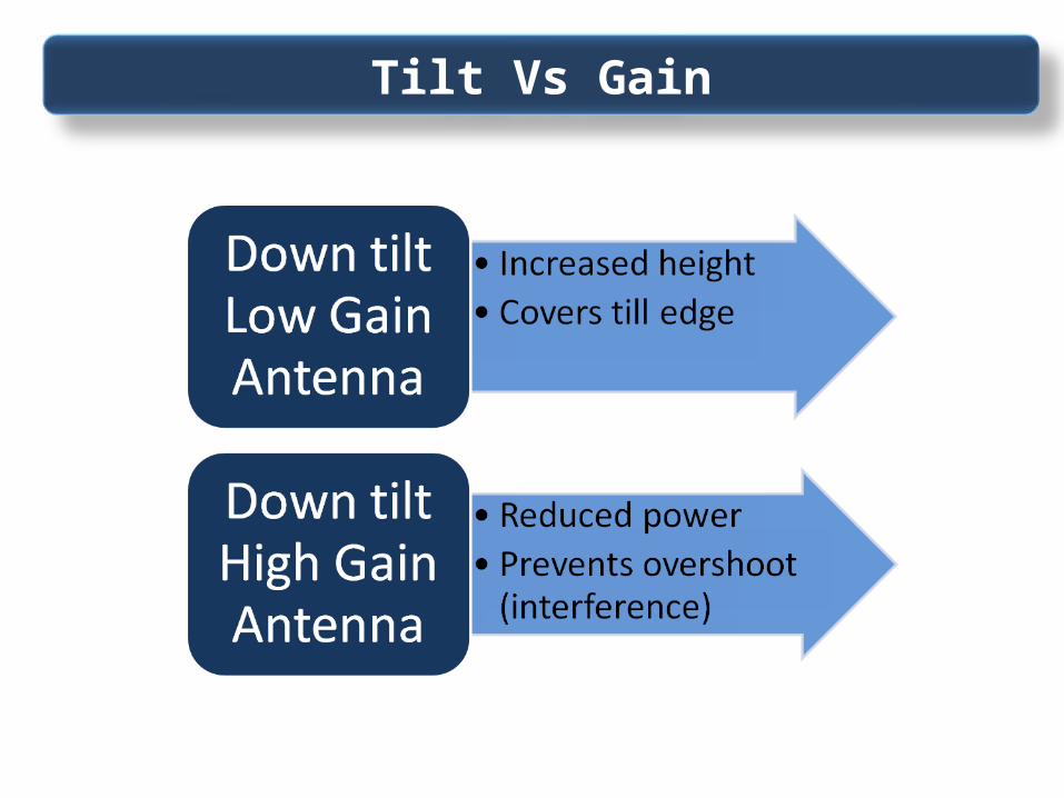
Tilt Vs Gain

BTS Command Interface
Procom Plus

Display Alarms (EAS/IAS)

DRI Status

Radios Classification/Configuration
SECTOR A GSM 900
DRI 0 0 0DRI 0 1 0DRI 0 2 0DRI 0 3 0
SECTOR B GSM 900 DRI 1 0 0DRI 1 1 0DRI 1 2 0DRI 1 3 0
SECTOR C GSM 900 DRI 2 0 0DRI 2 1 0DRI 2 2 0DRI 2 3 0
SECTOR A DCS 1800
DRI 3 0 0DRI 3 1 0DRI 3 2 0DRI 3 3 0
SECTOR B DCS 1800 DRI 4 0 0DRI 4 1 0DRI 4 2 0DRI 4 3 0
SECTOR C DCS 1800 DRI 5 0 0DRI 5 1 0DRI 5 2 0DRI 5 3 0
Common configuration with 3 DCS 1800 DRIs (one in each Sector) and 3 GSM 900 DRIs (one in each sector)
GSM 2/2/2 DCS 2/2/2

Alarms Equipage

BSC MMS Identifiers

Site IDs/Status

Site RSL Status

BSC RSLs Status
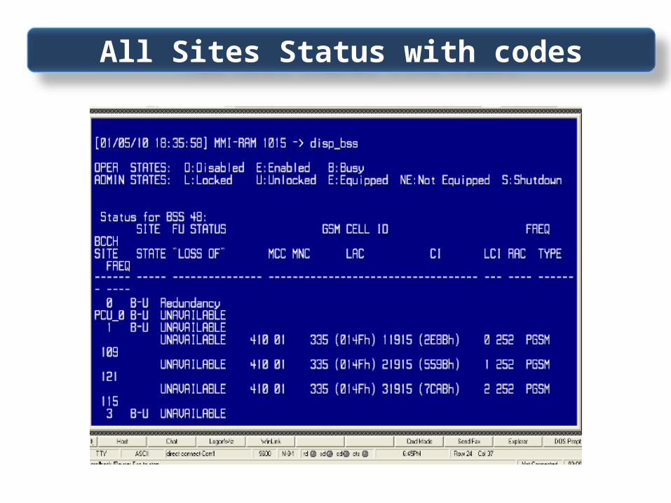
All Sites Status with codes

All Sites Status with codes

MMS Status

BSC OML Status
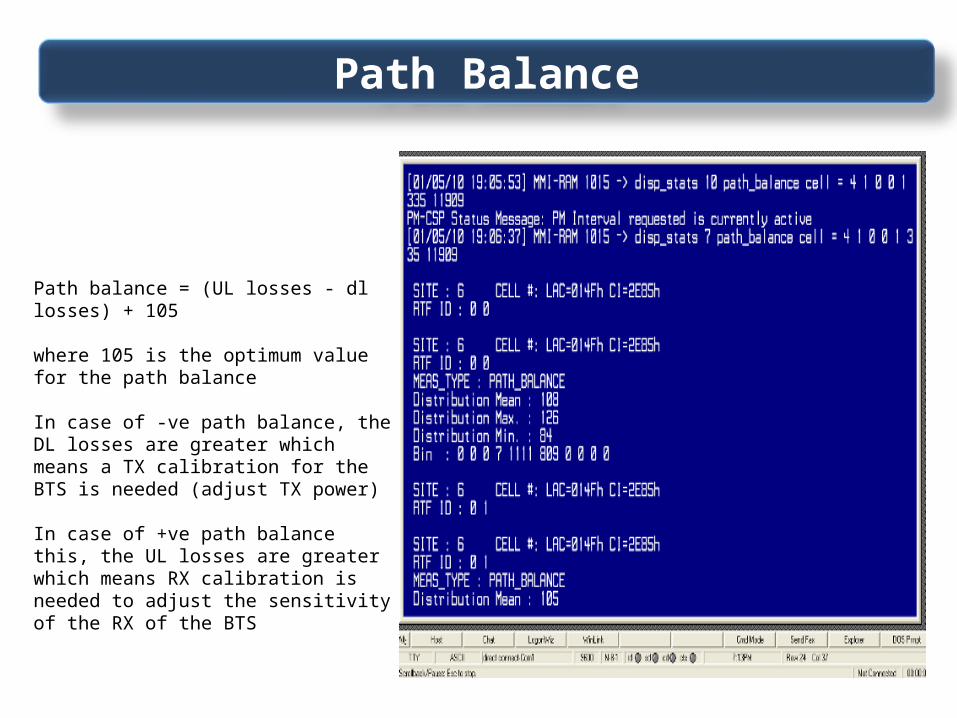
Path Balance
Path balance = (UL losses - dl losses) + 105
where 105 is the optimum value for the path balance
In case of -ve path balance, the DL losses are greater which means a TX calibration for the BTS is needed (adjust TX power)
In case of +ve path balance this, the UL losses are greater which means RX calibration is needed to adjust the sensitivity of the RX of the BTS

GSM Cell Data
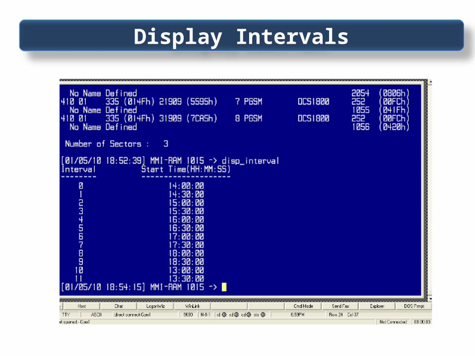
Display Intervals

DRI Equipage
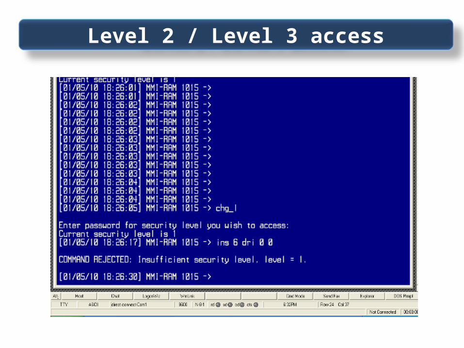
Level 2 / Level 3 access

DRI Calibration Data

BSC MTLs Status

BSC XBLs Status

BSS Test Equipments

Thanks