motivating sensor network applications & embedded systems design intro lecture 2 september 7,...
Post on 19-Dec-2015
221 views
TRANSCRIPT
Motivating Sensor Network Applications & Embedded Systems Design Intro
Lecture 2 September 7, 2004
EENG 460a / CPSC 436 / ENAS 960 Networked Embedded Systems &
Sensor Networks
Andreas [email protected]
Office: AKW 212Tel 432-1275
Course Websitehttp://www.eng.yale.edu/enalab/courses/eeng460a
Today’s Schedule
Homework#1 posted (Due Sept 21) Motivating applications for Sensor Networks Embedded Systems Design for embedded systems Next time – Q & A session on projects
• Last 15 minutes of class, come with ideas & questions
Reading for this lecture• [Edwards97] Design of Embedded Systems: Formal Models, Validation
and Synthesis

Homework 1 (Due Sept. 21)
Select one of the following topics and do a mini research assignment on it• Biomedical sensors• Inertial sensors• IEEE 802.15.4 Product and solutions• IEEE 1451 for smart distributed sensors• RFID Technologies• Energy Harvesting Solutions and Techniques• Design Tools for Embedded Systems
More detailed instructions posted on the website

Some Sensor Network Applications
Smart Environments: Smart Kindergarten ZipMotes and Ragobots Applications to entertainment
• Synchronization of video and sensor data• Check out paper “Augmenting Film and Video Footage with
Sensor Data Check out the sensor network applications at CENS
• http://www.cens.ucla.edu Any other projects you are aware of?

SensorsModules
High-speed Wireless LAN (WLAN)WLAN-Piconet
Bridge
Piconet
WLAN-PiconetBridge
WLAN AccessPoint
Piconet
SensorManagement
SensorFusion
SpeechRecognizer
Database& Data Miner
Sylph Middleware Framework
Wired Network
NetworkManagement
Networked Toys
Sensor Badge
Collaboration: Srivastava (EE) Muntz (CS) Alwan (EE) Potkonjak (CS) Baker (Education)
“Fusing the Physical and the Cognitive”
Smart Kindergarten Project: Technologies for Sensor-based Wireless Networks of Toysfor Smart Developmental Problem-solving Environments

Testbed Deployment & Experiments
Bluetooth
Ultrasound ToF
Localization and
Tracking Unit
Sylph Middleware
• 50 iBadge Nodes• 25 Medusa MK-2• 50 MICA motes
• Measured localization accuracy• Within 2cm of ground truth• 12 Measurements per second• Only free space experiments so far and some testing with obstucles

ZipMote Prototype
EENG 449b Project: Jimmy Zhang and Stephen Tully
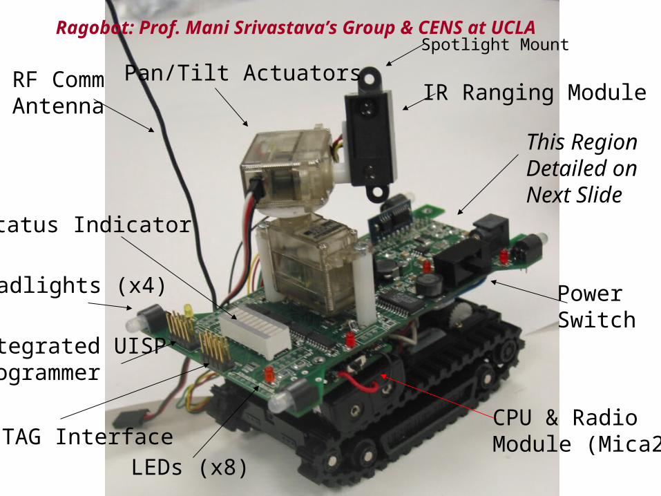
Status Indicator
Headlights (x4)
Integrated UISP Programmer
JTAG Interface
PowerSwitch
Spotlight Mount
IR Ranging ModulePan/Tilt ActuatorsRF Comm
Antenna
CPU & RadioModule (Mica2)
This RegionDetailed onNext Slide
LEDs (x8)
Ragobot: Prof. Mani Srivastava’s Group & CENS at UCLA
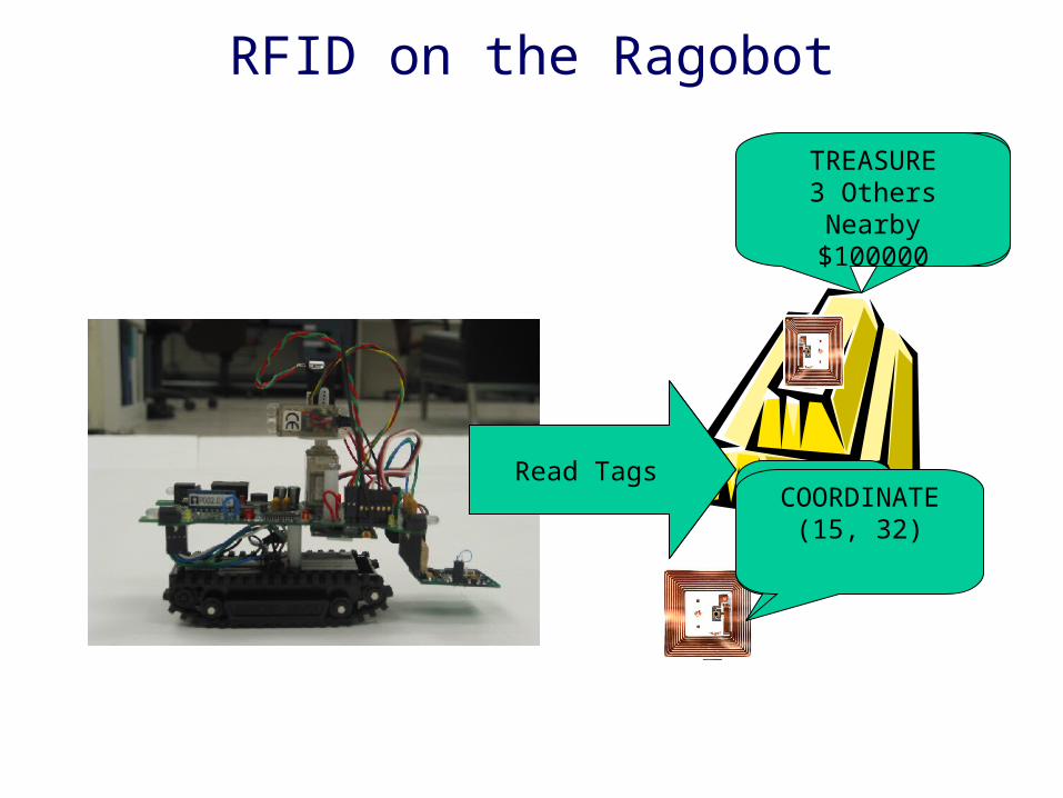
RFID on the Ragobot
Find ID
TAG ID: E0192039
TAG ID: E0191235
Read Tags
TREASURE3 Others Nearby
$100000
COORDINATE (15, 32)
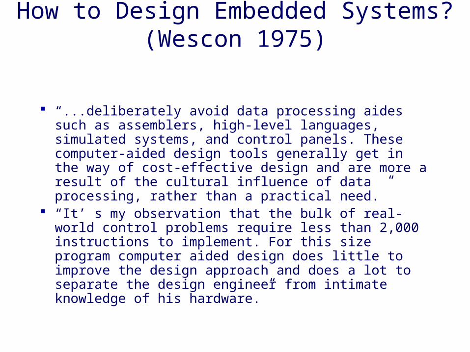
How to Design Embedded Systems? (Wescon 1975)
“...deliberately avoid data processing aides such as assemblers, high-level languages, simulated systems, and control panels. These computer-aided design tools generally get in the way of cost-effective design and are more a result of the cultural influence of data processing, rather than a practical need.”
“It’ s my observation that the bulk of real-world control problems require less than 2,000 instructions to implement. For this size program computer aided design does little to improve the design approach and does a lot to separate the design engineer from intimate knowledge of his hardware.”

Modeling Embedded Systems
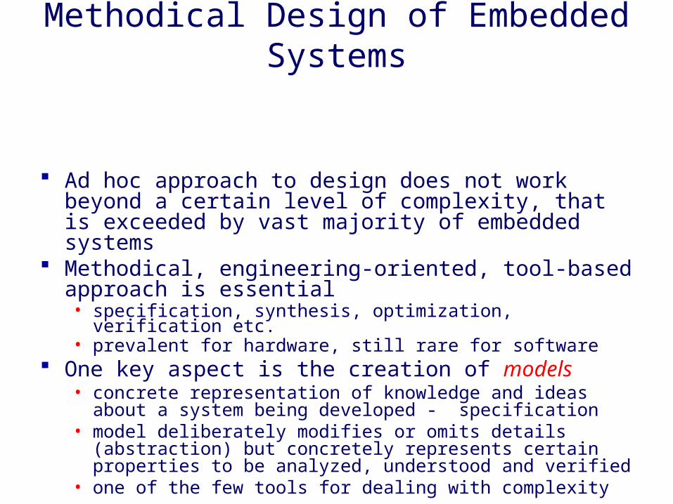
Methodical Design of Embedded Systems
Ad hoc approach to design does not work beyond a certain level of complexity, that is exceeded by vast majority of embedded systems
Methodical, engineering-oriented, tool-based approach is essential• specification, synthesis, optimization, verification etc.• prevalent for hardware, still rare for software
One key aspect is the creation of models• concrete representation of knowledge and ideas about a system being
developed - specification• model deliberately modifies or omits details (abstraction) but
concretely represents certain properties to be analyzed, understood and verified
• one of the few tools for dealing with complexity
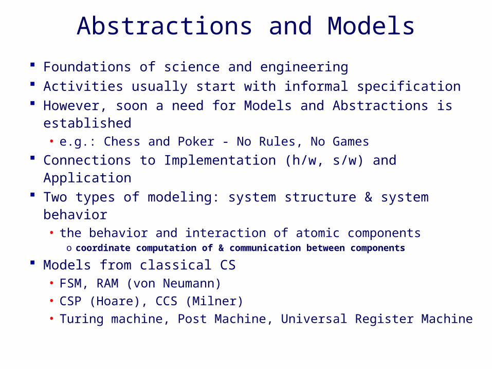
Abstractions and Models
Foundations of science and engineering Activities usually start with informal specification However, soon a need for Models and Abstractions is established
• e.g.: Chess and Poker - No Rules, No Games Connections to Implementation (h/w, s/w) and Application Two types of modeling: system structure & system behavior
• the behavior and interaction of atomic componentso coordinate computation of & communication between components
Models from classical CS• FSM, RAM (von Neumann)• CSP (Hoare), CCS (Milner)• Turing machine, Post Machine, Universal Register Machine
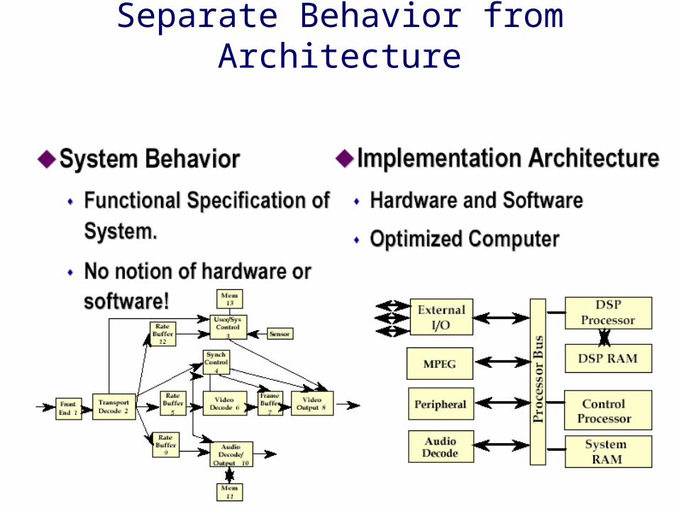
Separate Behavior from Architecture

Elements of a Model of a Computation System: Language
Set of symbols with superimposed syntax & semantics• textual (e.g. matlab), visual (e.g. labview) etc.
Syntax: rules for combining symbols• well structured, intuitive
Semantics: rules for assigning meaning to symbols and combinations of symbols• without rigorous semantics, precise model behavior over time is not well
defined• full executability and automatic h/w or s/w synthesis is impossible• E.g. operational semantics (in terms of actions of an abstract machine),
denotational semantics (in terms of relations)
Simulation and Synthesis
Two sides of the same coin Simulation: scheduling then execution on desktop
computer(s) Synthesis: scheduling then code generation in C++, C,
assembly, VHDL, etc. Validation by simulation important throughout design
flow Models of computation enable
• Global optimization of computation and communication
• Scheduling and communication that is correct by construction

Models Useful In Validating Designs
By construction• property is inherent.
By verification• property is provable.
By simulation• check behavior for all inputs.
By intuition• property is true. I just know it is.
By assertion• property is true. Wanna make something of it?
By intimidation• Don’t even try to doubt whether it is true
It is generally better to be higher in this list

Heterogeneous Systems
Hierarchical composition of models Need to understand how models relate when combined in a single system
[Evans]

Modeling Embedded Systems
Functional behavior: what does the system do• in non-embedded systems, this is sufficient
Contract with the physical world• Time: meet temporal contract with the environment
o temporal behavior important in real-time systems, as most embedded systems are
o simple metric such as throughput, latency, jittero more sophisticated quality-of-service metrics
• Power: meet constraint on power consumptiono peak power, average power, system lifetime
• Others: size, weight, heat, temperature, reliability etc.
System model must support description of bothfunctional behavior and physical interaction

Importance of Time in Embedded Systems: Reactive Operation
Computation is in response to external events• periodic events can be statically scheduled• aperiodic events harder
o worst case is an over-designo statistically predict and dynamically scheduleo approximate computation algorithms
As opposed to Transformation Operation in Interactive Systems
Transformational PhysicalProcessesREACTIVE
Reactive Operation (contd.)
Interaction with environment causes problems• indeterminacy in execution
o e.g. waiting for events from multiple sources
• physical environment is delay intoleranto can’t put it on wait with an hour glass icon!
Handling timing constraints are crucial to the design of embedded systems• interface synthesis, scheduling etc.
• increasingly, also implies high performance

Real Time Operation
Correctness of result is a function of time it is delivered: the right results on time!• deadline to finish computation• doesn’t necessarily mean fast: predictability is
important• worst case performance is often the issue
o but don’t want to be too pessimistic (and costly)
Accurate performance prediction needed

Shades of Real-time
Hard• the right results late are wrong!
o On-time = nanoseconds, microseconds, days…o Worst case performance is important
• catastrophic failure if deadline not met• safety-critical
Soft• the right results late are of less value than right results on time
o more they are late, less the value, but do not constitute system failureo usually average case performance is important
• failure not catastrophic, but impacts service qualityo e.g. connection timing out, display update in games
• most systems are largely soft real-time with a few hard real-time constraints (End-to-end) quality of service (QoS)
• notion from multimedia/OS/networking area• encompasses more than just timing constraints• classical real-time is a special case

Example: Characterizing Real-time Performance of an OS
Worst case interrupt disable time: The maximum duration that interrupts are disabled by the operating system, device driver or user software.
Worst case interrupt dispatch times: The maximum time from the processor recognizing the interrupt to the first instruction in the interrupt handler. There may be multiple such measurements, for different types of handlers, each with more or less capability.
Worst case kernel non-preemption time: The maximum duration that the kernel disables preemption of the running process to switch to a higher priority executable process.
Worst case process response time: The maximum time from a process schedule event (whether generated via a hardware interrupt or a software event) in the kernel to execution of the first instruction in the process.

Timing Constraints
Timing constraints are the key feature!o impose temporal restrictions on a system or its users
o hard timing constraints, soft timing constraints, interactive
Questions:o What kind of timing constraints are there?
o How do we arrange computation to take place such that it satisfies the timing constraints?

Many Notions of Time

Timing Constraints in a DSP Systems
Independent timing constraints: TS & TL
SYSTEM
Input samples
Output samples
i-1 i i+1 i+2 i+3 i+4
i-1 i i+1 i+2
Ts
TL
Latency vs. ThroughputWhich is “Harder” Real-time?
Throughputo constant rate case is easy
– double buffering helps, but no more
o bursty rate is harder, but large enough buffer is enough– as long as service rate = average throughput
Latency is MUCH hardero even a system with service rate = average throughput is
not sufficient
o need proper scheduling ,preemption etc.
More General Timing Constraints
Two categories of timing constraints• Performance constraints: set limits on response time of the system• Behavioral constraints: make demand on the rate at which users
supply stimuli to the system Further classification: three types of temporal restrictions (not
mutually exclusive)• Maximum: no more than t amount of time may elapse between the
occurrence of one event and the occurrence of another• Minimum: No less than t amount of time may elapse between two
events• Durational: an event must occur for t amount of time
Note: “Event” is either a stimulus to the system from its environment, or is an externally observable response that the system makes to its environment

More Complex Timing Constraints
Performance constraints on a sequence of responseso e.g. caller should dial 7 digits in 30s or less after lifting the receivero express using a timer
Durational: express duration of a stimulus or responseo e.g. to get back to the operator, press the button for at least 15s (but
not more than 30s); to get the dial tone press the button for more than 30s.
Two responses r1 and r2 should be heard within 60s after a stimulus s1, and r2 should be delayed at least by 15s after r1 and should occur within 30s after r1. Also, r1 & r2 should last for 3s and 4s respectively.

Popular Computation Models for Embedded Systems
Discrete Event Finite State Machines & Communicating
Finite State Machines Synchronous / Reactive Dataflow Process Networks Rendezvous-based Models (e.g CSP) Petri Nets

How do the models differ?
State: finite vs. infinite Time: untimed, continuous time, partial order,
global order Concurrency: sequential, concurrent Determinacy: determinate vs. indeterminate Data value: continuous, sample stream, event Communication mechanisms Others: composability, availability of tools etc.
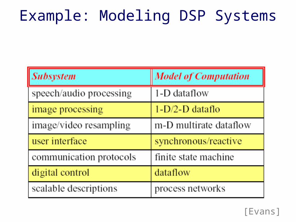
Example: Modeling DSP Systems
[Evans]
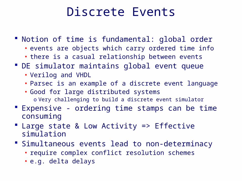
Discrete Events
Notion of time is fundamental: global order• events are objects which carry ordered time info• there is a casual relationship between events
DE simulator maintains global event queue• Verilog and VHDL• Parsec is an example of a discrete event language• Good for large distributed systems
o Very challenging to build a discrete event simulator
Expensive - ordering time stamps can be time consuming Large state & Low Activity => Effective simulation Simultaneous events lead to non-determinacy
• require complex conflict resolution schemes• e.g. delta delays
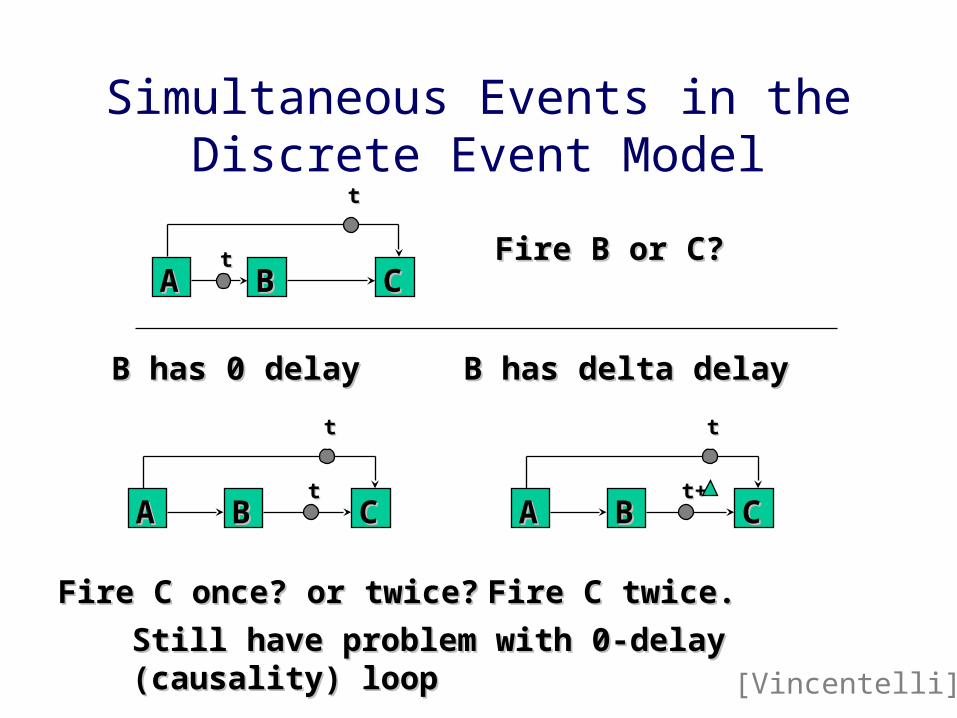
Simultaneous Events in the Discrete Event Model
AA BB CCtt
tt
Fire B or C?Fire B or C?
AA BB CC
tt
AA BB CC
tt
tt
B has 0 delayB has 0 delay B has delta delayB has delta delay
Fire C once? or twice?Fire C once? or twice?
t+t+
Fire C twice.Fire C twice.
Still have problem with 0-delay Still have problem with 0-delay (causality) loop(causality) loop [Vincentelli]
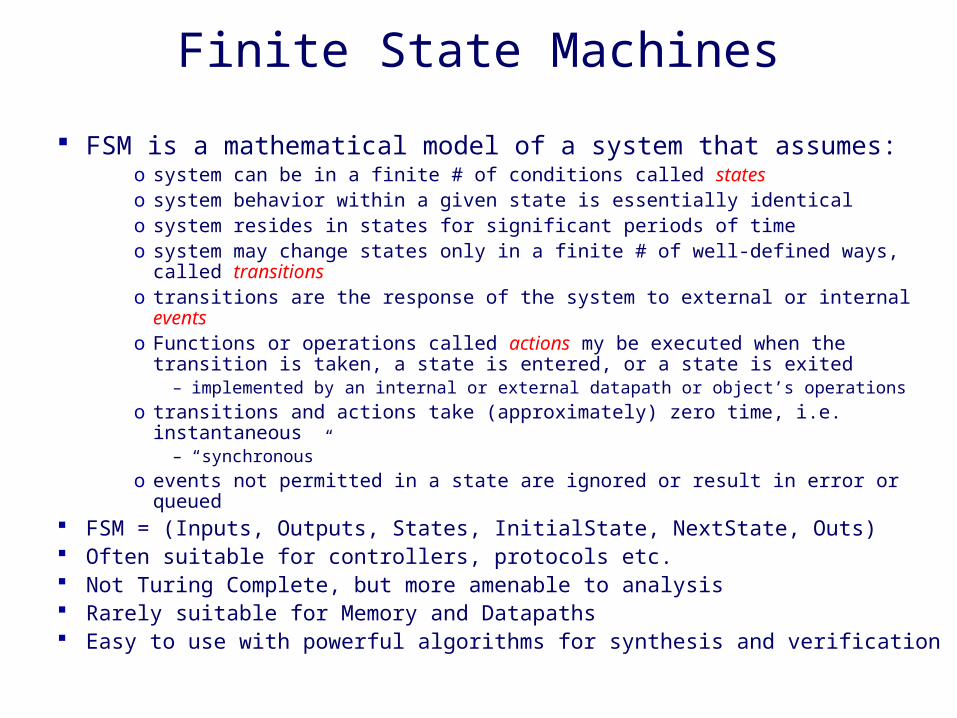
Finite State Machines
FSM is a mathematical model of a system that assumes:o system can be in a finite # of conditions called stateso system behavior within a given state is essentially identicalo system resides in states for significant periods of timeo system may change states only in a finite # of well-defined ways, called
transitionso transitions are the response of the system to external or internal eventso Functions or operations called actions my be executed when the transition is
taken, a state is entered, or a state is exited– implemented by an internal or external datapath or object’s operations
o transitions and actions take (approximately) zero time, i.e. instantaneous– “synchronous”
o events not permitted in a state are ignored or result in error or queued FSM = (Inputs, Outputs, States, InitialState, NextState, Outs) Often suitable for controllers, protocols etc. Not Turing Complete, but more amenable to analysis Rarely suitable for Memory and Datapaths Easy to use with powerful algorithms for synthesis and verification
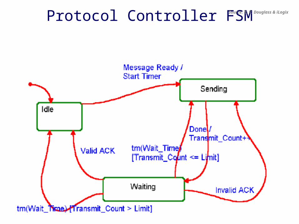
Protocol Controller FSM Source: B. P. Douglass & iLogix

FSM Example
Informal specificationif driver turns on the key and does not fasten seat belt within 5 seconds then sound the alarm for 5 seconds or until driver fastens the seat belt or turns off the key
Formal representationInputs = {KEY_ON, KEY_OFF, BELT_ON, BELT_OFF, 5_SECONDS_UP, 10_SECONDS_UPOutputs = {START_TIMER, ALARM_ON, ALARM_OFF}States = {Off, Wait, Alarm}Initial State = offNextState: CurrentState, Inputs -> NextStatee.g. NextState(WAIT, {KEY_OFF}) = OFF
Outs: CurrentStae, Inputs -> Outputse.g. Outs(OFF, {KEY_ON}) = START_TIMER

Radio control states from
the Chipcon CC2420
Radio (used on the XYZ sensor node)

Mealy-Moore FSMs
The set of states define the state space State space are flat
• all states are at the same level of abstraction• all state names are unique
State models are single threaded• only a single state can be valid at any time
Moore state models: all actions are upon state entry• Non-reactive (response delayed by a cycle)• Easy to compose (always well-defined)• Good for implementation
Mealy state models: all actions are in transitions• Reactive (0 response time)• Hard to compose: problem with combinational cycles• s/w or h/w must be fast enough: synchronous hypothesis
Source: B. P. Douglass & iLogix
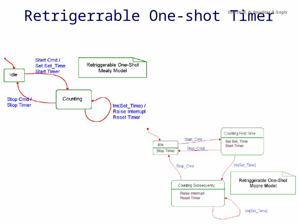
Retrigerrable One-shot TimerSource: B. P. Douglass & iLogix
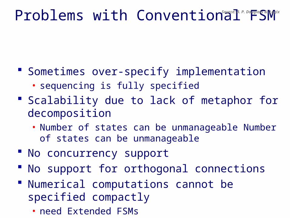
Problems with Conventional FSM
Sometimes over-specify implementation• sequencing is fully specified
Scalability due to lack of metaphor for decomposition• Number of states can be unmanageable Number of states can
be unmanageable
No concurrency support No support for orthogonal connections Numerical computations cannot be specified compactly
• need Extended FSMs
Source: B. P. Douglass & iLogix
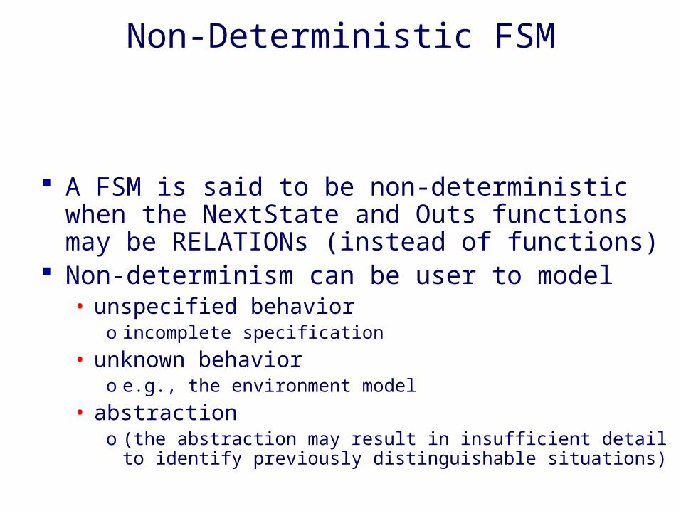
Non-Deterministic FSM
A FSM is said to be non-deterministic when the NextState and Outs functions may be RELATIONs (instead of functions)
Non-determinism can be user to model• unspecified behavior
o incomplete specification
• unknown behavioro e.g., the environment model
• abstractiono (the abstraction may result in insufficient detail to identify previously
distinguishable situations)
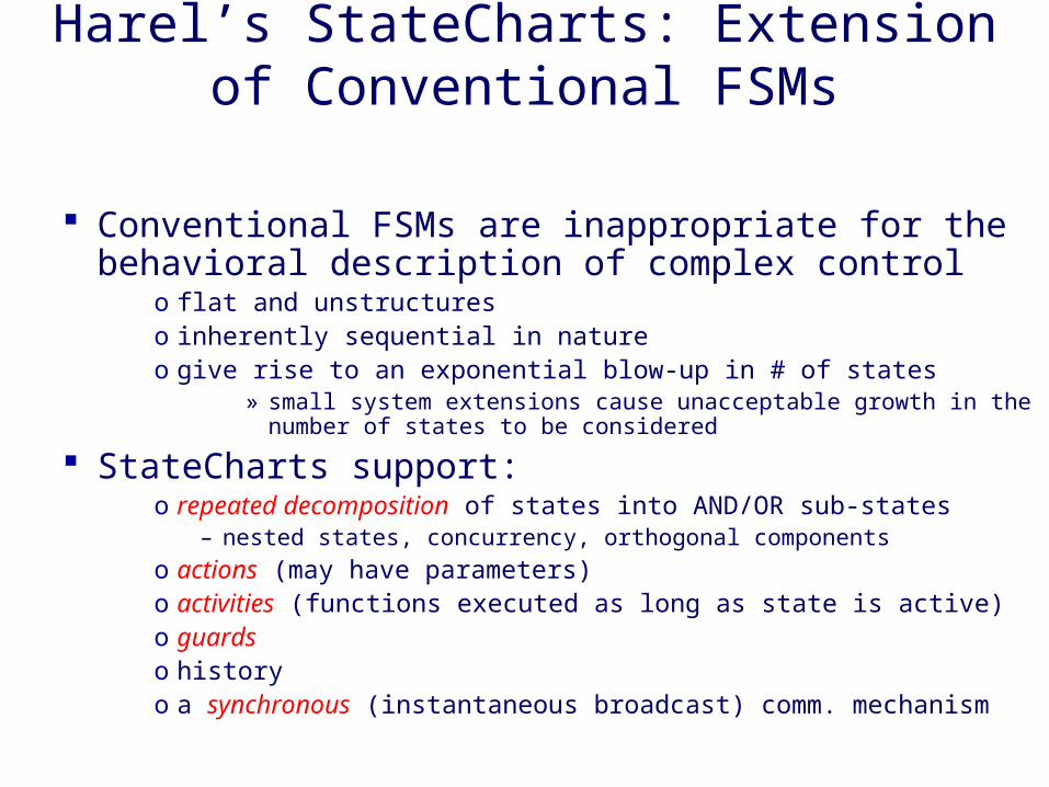
Harel’s StateCharts: Extension of Conventional FSMs
Conventional FSMs are inappropriate for the behavioral description of complex control
o flat and unstructureso inherently sequential in natureo give rise to an exponential blow-up in # of states
» small system extensions cause unacceptable growth in the number of states to be considered
StateCharts support:o repeated decomposition of states into AND/OR sub-states
– nested states, concurrency, orthogonal components
o actions (may have parameters)o activities (functions executed as long as state is active)o guardso historyo a synchronous (instantaneous broadcast) comm. mechanism
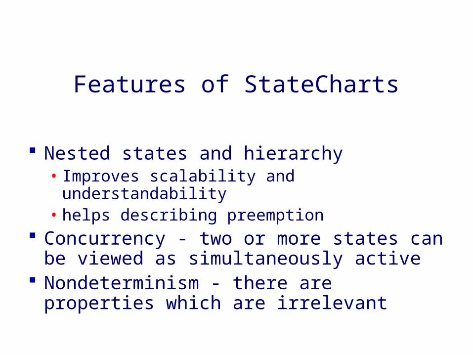
Features of StateCharts
Nested states and hierarchy• Improves scalability and understandability• helps describing preemption
Concurrency - two or more states can be viewed as simultaneously active
Nondeterminism - there are properties which are irrelevant

Example Concurrent FSMSource: B. P. Douglass & iLogix
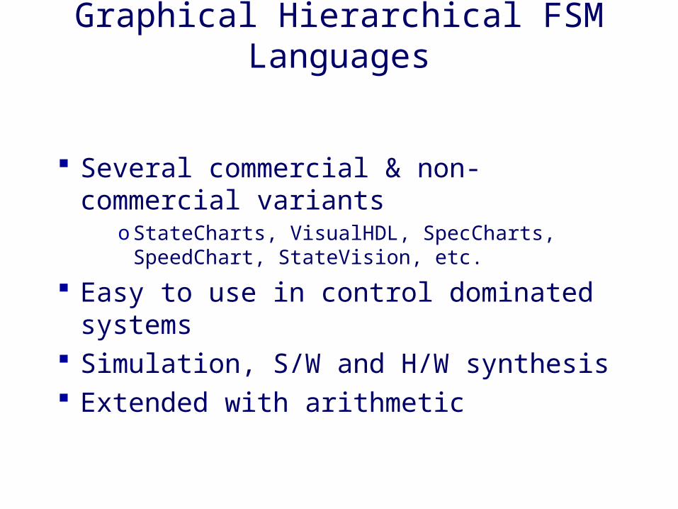
Graphical Hierarchical FSM Languages
Several commercial & non-commercial variants
o StateCharts, VisualHDL, SpecCharts, SpeedChart, StateVision, etc.
Easy to use in control dominated systems Simulation, S/W and H/W synthesis Extended with arithmetic
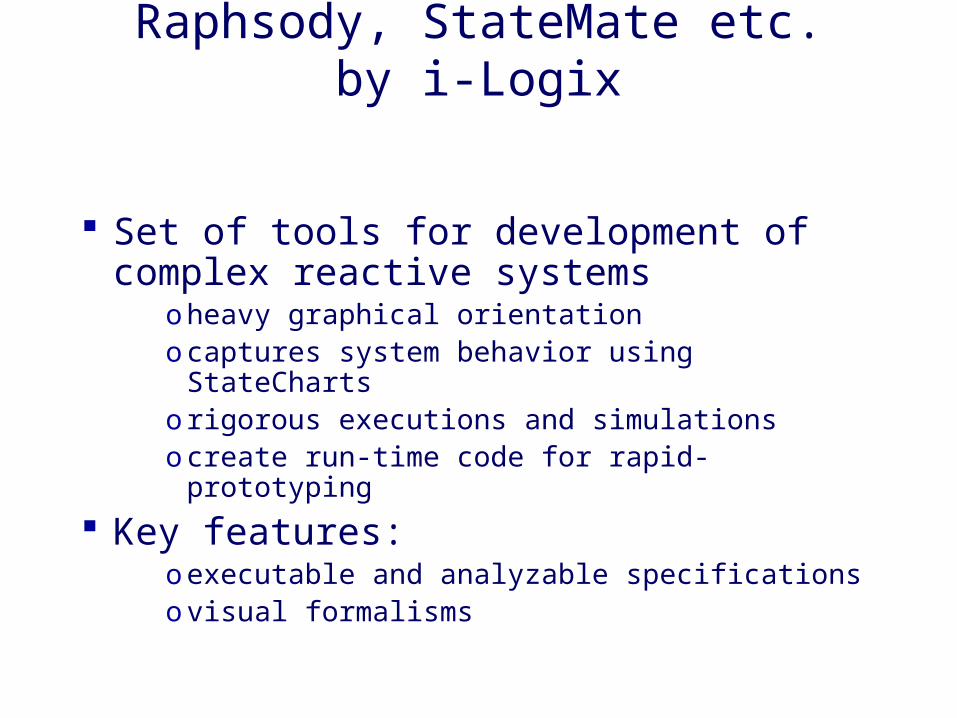
Raphsody, StateMate etc.by i-Logix
Set of tools for development of complex reactive systems
o heavy graphical orientationo captures system behavior using StateChartso rigorous executions and simulationso create run-time code for rapid-prototyping
Key features:o executable and analyzable specificationso visual formalisms

Reactive Synchronous Models
Assumptions• system reacts to internal and external events by emitting other
events• events can only occur at discrete time steps• reactions are assumed to be instantaneous
o communication by shared variables that are read & written in zero timeo Communication/computation happen instantaneously
– negligible or relatively small time to process event– if processing is significant, start & end events associated with tasks
Synchronous languages• Imperative: Estrel, Statechart• Dataflow: Lustre, Signal, Argos
Simple, clean semantics (FSM based), deterministic behavior, and lots of tools

Dataflow Process Networks
Graph: Nodes (actors) are computations, edges (arcs) are ordered sequences of events (tokens)
Kahn process network is generalization where unbounded FIFO buffering is available
Firing - quant of computation Karp-Miller computation graphs, Lee-Messerschmidt's
synchronous SDF, ...
A
B
C D

Synchronous vs. Asynchronous
Synchronous: StateChart, Esterel• communication by shared variables that are read & written in 0 time• communication and computation happens instantaneously at discrete
time instants (e.g. clock ticks & 0-delay computation)• all FSMs make a transition simultaneously (lock step)
o simultaneous signals: ordering imposed by dependencies
• may be difficult to implemento verify synchronous assumption on final designo Cycle time > max computation time
Asynchronous FSMs• free to proceed independently• do not execute a transition at the same time (except for rendezvous)• may need to share notion of time: synchronization• easy to implement but difficult to analyze
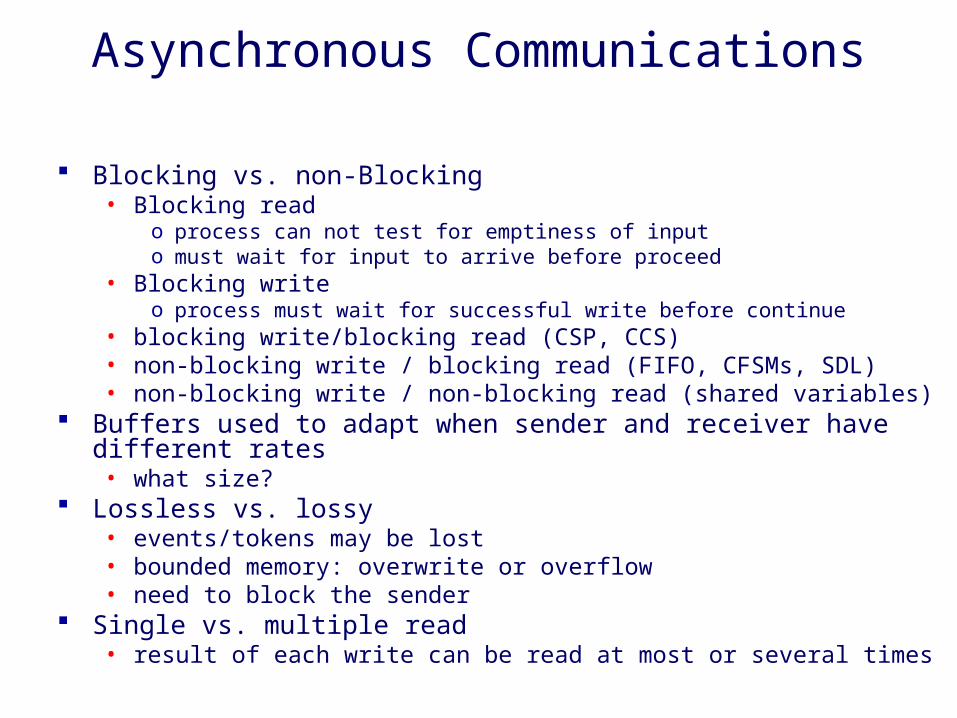
Asynchronous Communications
Blocking vs. non-Blocking• Blocking read
o process can not test for emptiness of inputo must wait for input to arrive before proceed
• Blocking writeo process must wait for successful write before continue
• blocking write/blocking read (CSP, CCS)• non-blocking write / blocking read (FIFO, CFSMs, SDL)• non-blocking write / non-blocking read (shared variables)
Buffers used to adapt when sender and receiver have different rates• what size?
Lossless vs. lossy• events/tokens may be lost• bounded memory: overwrite or overflow• need to block the sender
Single vs. multiple read• result of each write can be read at most or several times
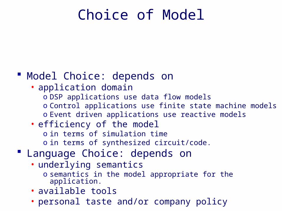
Choice of Model
Model Choice: depends on• application domain
o DSP applications use data flow modelso Control applications use finite state machine modelso Event driven applications use reactive models
• efficiency of the modelo in terms of simulation timeo in terms of synthesized circuit/code.
Language Choice: depends on• underlying semantics
o semantics in the model appropriate for the application.• available tools• personal taste and/or company policy