motherboard manual ga-8ir2003(rev2.0)_e
TRANSCRIPT

When you installing AGP card, please make sure the followingnotice is fully understood and practiced. If your AGP card has "AGP4X notch"(show below), please make sure your AGP card is AGP 4X(1.5V).
Do not use AGP 2X card (3.3V) in this motherboard. It will burn anddamage the motherboard due to Intel® 845(E/G) / 850(E) chipsetcan't support AGP 2X(3.3V).
Example 1: Diamond Vipper V770 golden finger is compatible with 2X/4Xmode AGP slot. It can be switched between AGP 2X(3.3V) or 4X (1.5V)mode by adjusting the jumper. The factory default for this card is 2X (3.3V).If you install this card in GA-8IR2003 (or any AGP 4X only) motherboardswithout switching the jumper to 4X mode (1.5V), it will burn the motherboard.
Example 2: Some ATi Rage 128 Pro graphics cards made by "Power Color",the graphics card manufacturer & some SiS 305 cards, their golden finger iscompatible with 2X/4X mode AGP slot, but they support 2X(3.3V) only. If youinstall this card in GA-8IR2003 (or any AGP 4X only) motherboards, it willburn the motherboard.
Note : Although Gigabyte's AG32S(G) graphics card is based on ATi Rage128 Pro chip, the design of AG32S(G) is compliance with AGP 4X (1.5V)specification. Therefore, AG32S(G) will work fine with Intel® 845(E/G) /850(E) based motherboards.

The author assumes no responsibility for any errors oromissions that may appear in this document nor doesthe author make a commitment to update the informa-tion contained herein.
Third-party brands and names are the property of theirrespective owners.
Please do not remove any labels on motherboard, thismay void the warranty of this motherboard.
Due to rapid change in technology, some of thespecifications might be out of date before publicationof this booklet.

Declaration of ConformityWe, Manufacturer/Importer
(full address)
declare that the product( description of the apparatus, system, installation to which it refers)
Mother BoardGA-8IR2003
is in conformity with(reference to the specification under which conformity is declared)
in accordance with 89/336 EEC-EMC Directive
EN 55011 Limits and methods of measurementof radio disturbance characteristics ofindustrial, scientific and medical (ISMhigh frequency equipment
EN 61000-3-2* EN 60555-2
Disturbances in supply systems causeby household appliances and similarelectrical equipment “Harmonics”
EN 55013 Limits and methods of measurementof radio disturbance characteristics ofbroadcast receivers and associatedequipment
EN 61000-3-3* Disturbances in supply systems causeby household appliances and similarelectrical equipment “Voltage fluctuations”
EN 55014 Limits and methods of measurementof radio disturbance characteristics ofhousehold electrical appliances,portable tools and similar electricalapparatus
EN 50081-1 Generic emission standard Part 1:Residual commercial and light industry
EN 50082-1 Generic immunity standard Part 1:Residual commercial and light industry
EN 55015 Limits and methods of measurementof radio disturbance characteristics offluorescent lamps and luminaries
Generic emission standard Part 2:Industrial environment
EN 55081-2
Immunity from radio interference ofbroadcast receivers and associatedequipment
Generic emission standard Part 2:Industrial environment
EN 55082-2
EN 55022 Limits and methods of measurementof radio disturbance characteristics ofinformation technology equipment
lmmunity requirements for householdappliances tools and similar apparatus
ENV 55104
Cabled distribution systems; Equipmentfor receiving and/or distribution fromsound and television signals
EMC requirements for uninterruptiblepower systems (UPS)
EN50091-2
EN 55020
DIN VDE 0855 part 10 part 12
(EC conformity marking) CE marking
The manufacturer also declares the conformity of above mentioned productwith the actual required safety standards in accordance with LVD 73/23 EEC
Safety requirements for mains operatedelectronic and related apparatus forhousehold and similar general use
EN 60950 EN 60065
Safety of household and similarelectrical appliances
EN 60335
Manufacturer/Importer
Signature:Name:(Stamp)
Date : May. 17, 2002
EN 60555-3
Timmy HuangTimmy Huang
EN 50091-1
Safety for information technology equipmentincluding electrical bussiness equipment
General and Safety requirements foruninterruptible power systems (UPS)
G.B.T. Technology Trading GMbHAusschlager Weg 41, 1F, 20537 Hamburg, Germany
..

FCC Part 15, Subpart B, Section 15.107(a) and Section 15.109(a),Class B Digital Device
DECLARATION OF CONFORMITYPer FCC Part 2 Section 2.1077(a)
Responsible Party Name:
Address:
Phone/Fax No:hereby declares that the product
Product Name:
Conforms to the following specifications:
This device complies with part 15 of the FCC Rules. Operation issubject to the following two conditions: (1) This device may notcause harmful and (2) this device must accept any inference received,including that may cause undesired operation.
Representative Person’s Name:
Signature: Eric Lu
Supplementary Information:
Model Number:
17358 Railroad StreetCity of Industry, CA 91748
G.B.T. INC. (U.S.A.)
(818) 854-9338/ (818) 854-9339
MotherboardGA-8IR2003
Date:
ERIC LU
May 17, 2 002

USER'S MANUAL
GA-8IR2003P4 Titan DDR Motherboard
Pentium® 4 Processor MotherboardRev. 2002
12ME-8IR2003-2002

- 2 -GA-8IR2003 Motherboard
Engl
ish Table of Content
Item Checklist ......................................................................................... 4WARNING! ............................................................................................... 4
Chapter 1 Introduction ............................................................................ 5Features Summary ...................................................................................... 5GA-8IR2003 Motherboard Layout ............................................................... 7
Chapter 2 Hardware Installation Process ............................................... 8Step 1: Install the Central Processing Unit (CPU)....................................... 9
Step 1-1: CPU Installation ................................................................................................ 9Step 1-2: CPU Heat Sink Installation ............................................................................10
Step 2: Install memory modules ................................................................ 11Step 3: Install expansion cards ................................................................. 13Step 4: Connect ribbon cables, cabinet wires and power supply ............ 14
Step 4-1: I/O Back Panel Introduction ...........................................................................14Step 4-2: Connectors Introduction .................................................................................16
Chapter 3 BIOS Setup ......................................................................... 27The Main Menu (For example: BIOS Ver. : E1) ........................................ 28Standard CMOS Features ......................................................................... 30Advanced BIOS Features .......................................................................... 33Integrated Peripherals .............................................................................. 35Power Management Setup ....................................................................... 39PnP/PCI Configurations ............................................................................. 42PC Health Status ........................................................................................ 43

Table of Content
English
- 3 -
Frequency/Voltage Control ........................................................................ 45Top Performance ...................................................................................... 47Load Fail-Safe Defaults ............................................................................. 48Load Optimized Defaults ........................................................................... 49Set Supervisor/User Password .................................................................. 50Save & Exit Setup ....................................................................................... 51Exit Without Saving ................................................................................... 52
Chapter 4 Technical Reference ........................................................... 53Block Diagram ........................................................................................... 53@BIOS™ Introduction ................................................................................. 54EasyTune™ 4 Introduction ......................................................................... 55Flash BIOS Method Introduction ............................................................... 56
Method 1 : Q-Flash ......................................................................................................... 56Method 2 : BIOS Flash Utility ........................................................................................ 58Method 3 : @BIOS Utility ................................................................................................ 69
2- / 4- / 6-Channel Audio Function Introuction .......................................... 71
Chapter 5 Appendix ............................................................................. 77
- 4 -GA-8IR2003 Motherboard
Engl
ish Item Checklist
Computer motherboards and expansion cards contain very delicate Integrated Circuit (IC) chips. Toprotect them against damage from static electricity, you should follow some precautions whenever youwork on your computer.
1. Unplug your computer when working on the inside.2. Use a grounded wrist strap before handling computer components. If you do not have one, touch
both of your hands to a safely grounded object or to a metal object, such as the power supplycase.
3. Hold components by the edges and try not touch the IC chips, leads or connectors, or othercomponents.
4. Place components on a grounded antistatic pad or on the bag that came with the componentswhenever the components are separated from the system.
5. Ensure that the ATX power supply is switched off before you plug in or remove the ATX powerconnector on the motherboard.
If the motherboard has mounting holes, but they don't line up with the holes on the base and there areno slots to attach the spacers, do not become alarmed you can still attach the spacers to the mountingholes. Just cut the bottom portion of the spacers (the spacer may be a little hard to cut off, so be careful ofyour hands). In this way you can still attach the motherboard to the base without worrying about shortcircuits. Sometimes you may need to use the plastic springs to isolate the screw from the motherboardPCB surface, because the circuit wire may be near by the hole. Be careful, don't let the screw contactany printed circuit write or parts on the PCB that are near the fixing hole, otherwise it may damage theboard or cause board malfunctioning.
Installing the motherboard to the chassis...
WARNING!
The GA-8IR2003 motherboardIDE cable x 1 / Floppy cable x 1CD for motherboard driver & utilityGA-8IR2003 user's manualI/O ShieldQuick PC Installation GuideRAID Manual
2 Port USB Cable x 14 Port USB Cable x 1SPDIF KIT x 1 (SPD-KIT)IEEE 1394 Cable x 1Audio Combo Kit x 1Motherboard Settings Label

Introduction
English
- 5 -
Form Factor 19.6cm x 29.5cm ATX size form factor, 4 layers PCBCPU Socket 478 for Intel® Micro FC-PGA2 Pentium® 4 processor
Support Intel® Pentium® 4 (Northwood, 0.13 m) processorSupport Intel® Pentium® 4 Processor with HT Technology *Intel® Pentium® 4 400/533MHz FSBAuto detect and optimized setting for Pentium® 4 processor2nd cache depends on CPU
Chipset Chipset Intel® 845 HOST/AGP/ControllerICH2 I/O Controller Hub
Memory 3 184-pin DDR DIMM socketsSupports PC2100 DDR or PC1600 DDR DIMMSupports up to 2GB DRAM (Max)Supports only 2.5V DDR DIMMSupports 64bit ECC type DRAM integrity mode
I/O Control ITE8712Slots 1 AGP slot 4X (1.5V) device support
5 PCI slot supports 33MHz & PCI 2.2 compliantOn-Board IDE 2 IDE bus master (DMA33/ATA66/ATA100) IDE ports for up to 4
ATAPI devicesSupports PIO mode3, 4 (UDMA 33/ATA66/ATA100) IDE & ATAPICD-ROM
On-Board Peripherals 1 Floppy port supports 2 FDD with 360K, 720K,1.2M, 1.44M and 2.88M bytes1 Parallel port supports Normal/EPP/ECP mode2 Serial ports (COMA & COMB)4 x USB 1.1 (2 by cable )1 Front Audio connector
Hardware Monitor CPU/System fan revolution detectCPU temperature detectCPU warning temperatureSystem voltage detectCPU/System fan fail warning
to be continued......
Chapter 1 IntroductionFeatures Summary

- 6 -GA-8IR2003 Motherboard
Engl
ish On-Board Sound Realtek ALC650 CODEC
Line Out / 2 front speakerLine In / 2 rear speaker(by s/w switch)Mic In / center & subwoofer(by s/w switch)SPDIF In / OutCD In / AUX In / Game port
PS/2 Connector PS/2 Keyboard interface and PS/2 Mouse interfaceBIOS Licensed AWARD BIOS, 2M bit FWH
Supports Q-FlashAdditional Features PS/2 Keyboard password power on
PS/2 Mouse power onSTR(Suspend-To-RAM)AC RecoveryUSB KB/Mouse wake up from S3Poly fuse for keyboard, USB, game port over-current protectionSupports @BIOSSupports EasyTune 4
Jumper less Over Clock (CPU/DDR/AGP) by BIOSOverclocking
Please set the CPU host frequency in accordance with your processor's specifications.We don't recommend you to set the system bus frequency over the CPU's specification becausethese specific bus frequencies are not the standard specifications for CPU, chipset and most of theperipherals. Whether your system can run under these specific bus frequencies properly willdepend on your hardware configurations, including CPU, Chipsets, SDRAM, Cards…etc.
"*" HT functionality requirement content :Enabling the functionality of Hyper-Threading Technology for your computer system requires allof the following platform components:- CPU: An Intel® Pentium 4 Processor with HT Technology- Chipset: An Intel® Chipset that supports HT Technology- BIOS: A BIOS that supports HT Technology and has it enabled- OS: An operation system that has optimizations for HT Technology

Hardware Installation Process
English
- 7 -
GA-8IR2003 Motherboard Layout
GA-8I
R200
3
KB_MS
COMA
SPDIF_IO
LPT
GAME
LINE_
INLINE_
OUT
MIC_
IN
USB
ATX_12V
CD_IN
F_AUDIO
F_PANEL
BATTERY
SYS _FAN
ICH2
SOCKET478
CPU_FAN
ATX
FDD
IDE1
IDE2
ITE8712
PCI1
PCI2
PCI3
DDR2
DDR1
CODEC
F_USB1
COMB
DDR3
BIOS
PCI4
PCI5
AUX_IN
SUR_CEN
CI
AGP
P4 Titan
PWR_LED
Intel 845
CLR_PWD
2X_DET

- 8 -GA-8IR2003 Motherboard
Engl
ish
To set up your computer, you must complete the following steps:Step 1- Install the Central Processing Unit (CPU)Step 2- Install memory modulesStep 3- Install expansion cardsStep 4- Connect ribbon cables, cabinet wires, and power supplyStep 5- Setup BIOS softwareStep 6- Install supporting software tools
Chapter 2 Hardware Installation Process
Step 2Step 4
Step 3
Step 4
Step 4
Step 1
Step 4
Step 1

Hardware Installation Process
English
- 9 -
Step 1: Install the Central Processing Unit (CPU)Step 1-1: CPU Installation
Please make sure the CPU type is supported by the motherboard.If you do not match the CPU socket Pin 1 and CPU cut edge well, it will causeimproper installation. Please change the insert orientation.
Angling therod to 650
1. Angling the rod to 65-degree maybe feel akind of tight , and then continue pull the rod to90-degree when a noise "cough" made.
2. Pull the rod to the 90-degree directly .
Pin1 indicator
3. CPU Top View
Pin1 indicator
4. Locate Pin 1 in the socket and lookfor a (golden) cut edge on the CPUupper corner. Then insert the CPUinto the socket.
SocketActuationLever

- 10 -GA-8IR2003 Motherboard
Engl
ish Step 1-2: CPU Heat Sink Installation
Please use Intel approved cooling fan.We recommend you to apply the thermal tape to provide better heatconduction between your CPU and heatsink.(The CPU cooling fan might stick to the CPU due to the hardening of thethermal paste. During this condition if you try to remove the cooling fan, youmight pull the processor out of the CPU socket alone with the cooling fan, andmight damage the processor. To avoid this from happening, we suggest you toeither use thermal tape instead of thermal paste, or remove the cooling fan withextreme caution.)Make sure the CPU fan power cable is plugged in to the CPU fan connector,this completes the installation.Please refer to CPU heat sink user's manual for more detail installationprocedure.
1. Hook one end of the cooler bracketto the CPU socket first.
2. Hook the other end of the coolerbracket to the CPU socket.

Hardware Installation Process
English
- 11 -
Step 2: Install memory modules
The motherboard has 3 dual inline memory module (DIMM) sockets, but it can only support a maximumof 4 banks of DDR memory. DDR slot 1 uses 2 banks, DDR slot 2 & 3 share the remaining 2 banks.Please refer to the following tables for possible memory configurations supported. The BIOS willautomatically detects memory type and size. To install the memory module, just push it vertically into theDIMM socket. The DIMM module can only fit in one direction due to the notch. Memory size can varybetween sockets.
Total Memory Sizes With Unbuffered DDR DIMM Devices used on DIMM 1 DIMM x 64 / x 72 2 DIMMs x 64 / x 72 3 DIMMs x 64 / x 72 64 Mbit (2Mx8x4 banks) 128 MBytes 256 MBytes 256 MBytes 64 Mbit (1Mx16x4 banks) 32 MBytes 64 MBytes 96 MBytes 128 Mbit(4Mx8x4 banks) 256 MBytes 512 MBytes 512 MBytes 128 Mbit(2Mx16x4 banks) 64 MBytes 128 MBytes 192 MBytes 256 Mbit(8Mx8x4 banks) 512 MBytes 1 GBytes 1 GBytes 256 Mbit(4Mx16x4 banks) 128 MBytes 256 MBytes 384 MBytes 512 Mbit(16Mx8x4 banks) 1 GBytes 2 GBytes 2 GBytes 512 Mbit(8Mx16x4 banks) 256 MBytes 512 MBytes 768 MBytes
DDR1 DDR2 DDR3S S SD S SD D XD X DS D XS X D
D: Double Sided DIMM S:Single Sided DIMMX: Not Use

- 12 -GA-8IR2003 Motherboard
Engl
ish
Please note that the DIMM module can only fit in one direction due to the onenotch. Wrong orientation will cause improper installation. Please change theinsert orientation.
DDR
1. The DIMM socket has a notch, so the DIMM memorymodule can only fit in one direction.
2. Insert the DIMM memory module vertically into the DIMMsocket. Then push it down.
3. Close the plastic clip at both edges of the DIMM socketsto lock the DIMM module.Reverse the installation steps when you wish to removethe DIMM module.
Established on the existing SDRAM industry infrastructure, DDR (Double Data Rate) memory is ahigh performance and cost-effective solution that allows easy adoption for memory vendors, OEMs andsystem integrators.
DDR memory is a sensible evolutionary solution for the PC industry that builds on the existingSDRAM infrastructure, yet makes awesome advances in solving the system performance bottleneck bydoubling the memory bandwidth. DDR SDRAM will offer a superior solution and migration path fromexisting SDRAM designs due to its availability, pricing and overall market support. PC2100 DDRmemory (DDR266) doubles the data rate through reading and writing at both the rising and falling edge ofthe clock, achieving data bandwidth 2X greater than PC133 when running with the same DRAM clockfrequency. With peak bandwidth of 2.664GB per second, DDR memory enables system OEMs to buildhigh performance and low latency DRAM subsystems that are suitable for servers, workstations, high-end PC's and value desktop SMA systems. With a core voltage of only 2.5 Volts compared toconventional SDRAM's 3.3 volts, DDR memory is a compelling solution for small form factor desktopsand notebook applications.
DDR Introduction
Hardware Installation Process
English
- 13 -
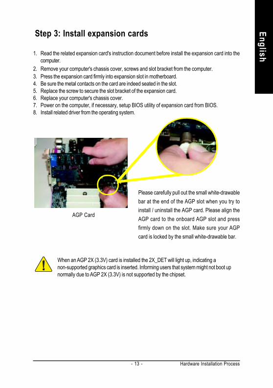
Step 3: Install expansion cards
1. Read the related expansion card's instruction document before install the expansion card into thecomputer.
2. Remove your computer's chassis cover, screws and slot bracket from the computer.3. Press the expansion card firmly into expansion slot in motherboard.4. Be sure the metal contacts on the card are indeed seated in the slot.5. Replace the screw to secure the slot bracket of the expansion card.6. Replace your computer's chassis cover.7. Power on the computer, if necessary, setup BIOS utility of expansion card from BIOS.8. Install related driver from the operating system.
AGP Card
Please carefully pull out the small white-drawablebar at the end of the AGP slot when you try toinstall / uninstall the AGP card. Please align theAGP card to the onboard AGP slot and pressfirmly down on the slot. Make sure your AGPcard is locked by the small white-drawable bar.
When an AGP 2X (3.3V) card is installed the 2X_DET will light up, indicating anon-supported graphics card is inserted. Informing users that system might not boot upnormally due to AGP 2X (3.3V) is not supported by the chipset.

- 14 -GA-8IR2003 Motherboard
Engl
ish Step 4: Connect ribbon cables, cabinet wires and
power supply
Step 4-1: I/O Back Panel Introduction
PS/2 Keyboard and PS/2 Mouse Connector
This connector supports standard PS/2keyboard and PS/2 mouse.
PS/2 Mouse Connector(6 pin Female)
PS/2 Keyboard Connector(6 pin Female)
USB Connector Before you connect your device(s) into USBconnector(s), please make sure your device(s)such as USB keyboard,mouse, scanner, zip,speaker...etc. Have a standard USB interface.Also make sure your OS supports USB controller.If your OS does not support USB controller, pleasecontact OS vendor for possible patch or driverupgrade. For more information please contact yourOS or device(s) vendors.
USB 0USB 1

Hardware Installation Process
English
- 15 -
Parallel Port and Serial Ports (COMA / COMB)
This connector supports 2 standard COM portsand 1 Parallel port. Device like printer can beconnected to Parallel port; mouse and modemetc. can be connected to Serial ports.
Parallel Port(25 pin Female)
COMA COMBSerial Port (9 pin Male)
Game / MIDI Ports
Audio Connectors
This connector supports joystick, MIDIkeyboard and other relate audio devices.
After install onboard audio driver, you may con-nect speaker to Line Out jack, microphone to MICIn jack. Device like CD-ROM,walkman etc. canbe connected to Line-In jack.Please note:You are able to use 2-/4-/6-channel audio featureby S/W selection.If you want to enable 6-channel function, youhave 2 choose for hardware connection.Method1:Connect "Front Speaker" to "Line Out"Connect "Rear Speaker" to "Line In"Connect "Center and Subwoofer" to "MIC Out ".Method2:You can refer to page 22, and contact yournearest dealer for optional SUR_CEN cable.
MIC In(Center andSubwoofer)
Line Out(Front Speaker)
Line In(Rear Speaker)
If you want the detail information for 2-/4-/6-channel audio setupinstallation, please refer to page 71.
Joystick/ MIDI (15 pin Female)

- 16 -GA-8IR2003 Motherboard
Engl
ish Step 4-2: Connectors Introduction
4
16
2
5
12 18
11
8
715
6
13
3
10
1
1) ATX_12V2) ATX3) CPU_FAN4) SYS_FAN5) FDD6) IDE1 / IDE27) F_PANEL8) PWR_LED9) 2X_DET
10) F_AUDIO11) SUR_CEN12) CD_IN13) AUX_IN14) SPDIF_IO15) F_USB116) CI17) CLR_PWD18) BATTERY
14
17
9

Hardware Installation Process
English
- 17 -
1) ATX_12V (+12V Power Connector)This connector (ATX_12V) supplies the CPU operation voltage (Vcore).If this "ATX_12V connector" is not connected, system cannot boot.
Pin No. Definition1 GND2 GND3 +12V4 +12V
2) ATX (ATX Power)AC power cord should only be connected to your power supply unit after ATX power cable andother related devices are firmly connected to the mainboard.
Pin No. Definition1 3.3V2 3.3V3 GND4 VCC5 GND6 VCC7 GND8 Power Good9 5V SB (stand by +5V)
10 +12V11 3.3V12 -12V13 GND14 PS_ON(soft on/off)15 GND16 GND17 GND18 -5V19 VCC20 VCC
4 32 1
20
1 11
10

- 18 -GA-8IR2003 Motherboard
Engl
ish 3) CPU_FAN (CPU Fan Connector)
Please note, a proper installation of the CPU cooler is essential to prevent the CPU from runningunder abnormal condition or damaged by overheating. The CPU fan connector supports Max.current up to 600 mA.
Pin No. Definition1 GND2 +12V3 Sense
4) SYS_FAN (System Fan Connector)This connector allows you to link with the cooling fan on the system case to lower the systemtemperature.
Pin No. Definition1 GND2 +12V3 Sense
1
1

Hardware Installation Process
English
- 19 -
5) FDD (Floppy Connector)Please connect the floppy drive ribbon cables to FDD. It supports 360K, 1.2M, 720K, 1.44M and2.88M bytes floppy disk types.The red stripe of the ribbon cable must be the same side with the Pin1.
6) IDE1 / IDE2 (IDE1 / IDE2 Connector)Important Notice:Please connect first hard disk to IDE1 and connect CD-ROM to IDE2.The red stripe of the ribbon cable must be the same side with the Pin1.
1
33
2
34
IDE1
139
240
IDE2

- 20 -GA-8IR2003 Motherboard
Engl
ish 7) F_PANEL (2 x 10 pins Connector)
Please connect the power LED, PC speaker, reset switch and power switch etc of your chassisfrontpanel to the F_PANEL connector according to the pin assignment above.
HD (IDE Hard Disk Active LED) Pin 1: LED anode(+)(Blue) Pin 2: LED cathode(-)SPK (Speaker Connector) Pin 1: VCC(+)(Amber) Pin 2- Pin 3: NC
Pin 4: Data(-)RES (Reset Switch) Open: Normal Operation(Green) Close: Reset Hardware SystemPW (Soft Power Connector) Open: Normal Operation(Red) Close: Power On/OffMSG(Message LED/ Power/ Sleep LED) Pin 1: LED anode(+)(Yellow) Pin 2: LED cathode(-)NC (Purple) N C
12
1920
HD-
HD+ RE
S-RE
S+ NC
IDE Hard Disk Active LED
Reset Switch
SPEA
K-
MSG-
MSG+
PW-
PW+
Message LED/Power/Sleep LED
Speaker Connector
SPEA
K+
1 1
1 1 1
Soft PowerConnector

Hardware Installation Process
English
- 21 -
+_
8) PWR_LEDPWR_LED is connect with the system power indicator to indicate whether the system is on/off.It will blink when the system enters suspend mode. If you use dual color LED, power LED will turnto another color.
Pin No. Definition1 MPD+2 MPD-3 MPD-
1
9) 2X_DETWhen an AGP 2X (3.3V) card is installed the AGP_LED will light up, indicating a non-supportedgraphics card is inserted. Informing users that system might not boot up normally due to AGP 2X(3.3V) is not supported by the chipset.

- 22 -GA-8IR2003 Motherboard
Engl
ish 10) F_AUDIO (Front Audio Connector)
If you want to use Front Audio connector, you must remove 5-6, 9-10 Jumper.In order to utilize the front audio header, your chassis must have front audio connector. Also pleasemake sure the pin assigment on the cable is the same as the pin assigment on the MB header. Tofind out if the chassis you are buying support front audio connector, please contact your dealer.Please note, you can have the of using front audio connector or of using rear audio connector toplay sound.
Pin No. Definition1 MIC2 GND3 REF4 Power5 Front Audio (R)6 Rear Audio (R)7 Reserved8 No Pin9 Front Audio (L)10 Rear Audio (L)
11) SUR_CEN (Surround Center Connector)Please contact your nearest dealer for optional SUR_CEN cable.
Pin No. Definition1 SUR OUTL2 SUR OUTR3 GND4 No Pin5 CENTER_OUT6 BASS_OUT
165
2
1
109
2

Hardware Installation Process
English
- 23 -
12) CD_IN (CD In Connector)Connect CD-ROM or DVD-ROM audio out to the connector.
1 Pin No. Definition1 AUX-L2 GND3 GND4 AUX-R
13) AUX_IN (AUX In Connector)Connect other device (such as PCI TV Tunner audio out) to the connector.
Pin No. Definition1 AUX-L2 GND3 GND4 AUX-R
1

- 24 -GA-8IR2003 Motherboard
Engl
ish
15) F_USB1 (Front USB Connector, Yellow)Be careful with the polarity of the front USB connector. Check the pin assignment while youconnect the front USB cable. Please contact your nearest dealer for optional front USB cable.
Pin No. Definition1 Power2 Power3 USB Dx-4 USB Dy-5 USB Dx+6 USB Dy+7 GND8 GND9 No Pin10 NC
14) SPDIF_IO (SPDIF In / Out)The SPDIF output is capable of providing digital audio to external speakers or compressed AC3data to an external Dolby Digital Decoder. Use this feature only when your stereo system hasdigital input function. Use SPDIF IN feature only when your device has digital output function.
Pin No. Definition1 VCC2 No Pin3 SPDIF4 SPDIFI5 GND6 GND
1 9F_USB1
2 10
1
6 2
5

Hardware Installation Process
English
- 25 -
17) CLR_PWDWhen Jumper is set to "open" and system is restarted, the password that is set will be cleared.On the contrary when Jumper is set to "close", the current status remains.
1
1
Open: Clear Password
Close: Normal
16) CI (CASE OPEN)This 2-pin connector allows your system to enable or disable the "Case Open" item in BIOS, if thesystem case begin remove.
Pin No. Definition1 Signal2 GND1

- 26 -GA-8IR2003 Motherboard
Engl
ish 18) BATTERY
CAUTIONDanger of explosion if battery is incorrectlyreplaced.Replace only with the same or equivalent typerecommended by the manufacturer.Dispose of used batteries according to themanufacturer's instructions.
+
If you want to erase CMOS...1. Turn OFF the computer and unplug the power cord.2. Remove the battery, wait for 30 second.3. Re-install the battery.4. Plug the power cord and turn ON the computer.
BIOS Setup
English
- 27 -
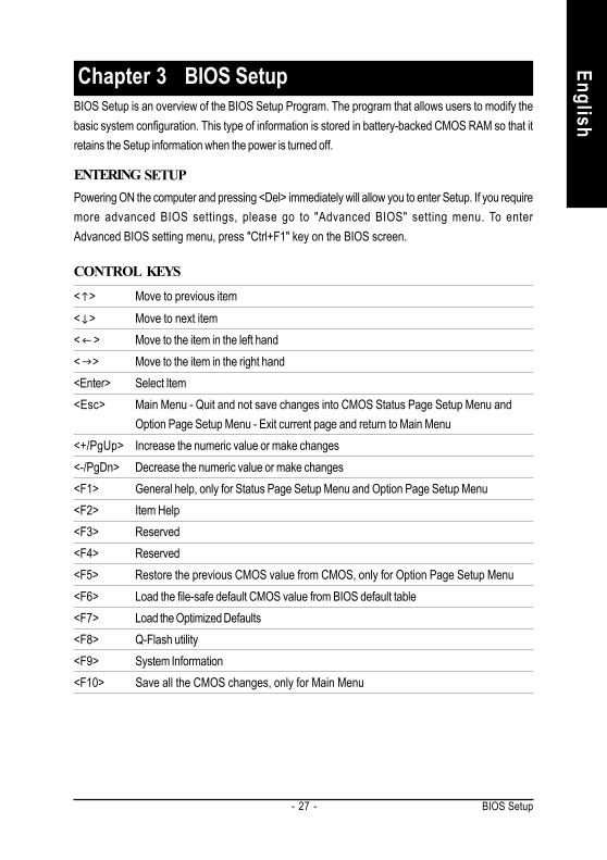
< > Move to previous item< > Move to next item< > Move to the item in the left hand< > Move to the item in the right hand<Enter> Select Item<Esc> Main Menu - Quit and not save changes into CMOS Status Page Setup Menu and
Option Page Setup Menu - Exit current page and return to Main Menu<+/PgUp> Increase the numeric value or make changes<-/PgDn> Decrease the numeric value or make changes<F1> General help, only for Status Page Setup Menu and Option Page Setup Menu<F2> Item Help<F3> Reserved<F4> Reserved<F5> Restore the previous CMOS value from CMOS, only for Option Page Setup Menu<F6> Load the file-safe default CMOS value from BIOS default table<F7> Load the Optimized Defaults<F8> Q-Flash utility<F9> System Information<F10> Save all the CMOS changes, only for Main Menu
BIOS Setup is an overview of the BIOS Setup Program. The program that allows users to modify thebasic system configuration. This type of information is stored in battery-backed CMOS RAM so that itretains the Setup information when the power is turned off.
Chapter 3 BIOS Setup
ENTERINGPowering ON the computer and pressing <Del> immediately will allow you to enter Setup. If you requiremore advanced BIOS settings, please go to "Advanced BIOS" setting menu. To enterAdvanced BIOS setting menu, press "Ctrl+F1" key on the BIOS screen.
CONTROL
SETUP
KEYS

- 28 -GA-8IR2003 Motherboard
Engl
ish
Standard CMOS FeaturesThis setup page includes all the items in standard compatible BIOS.Advanced BIOS FeaturesThis setup page includes all the items of Award special enhanced features.
Main MenuThe on-line description of the highlighted setup function is displayed at the bottom of the screen.
Status Page Setup Menu / Option Page Setup MenuPress F1 to pop up a small help window that describes the appropriate keys to use and the possibleselections for the highlighted item. To exit the Help Window press <Esc>.
The Main Menu (For example: BIOS Ver. : E1)Once you enter Award BIOS CMOS Setup Utility, the Main Menu (Figure 1) will appear on the screen.The Main Menu allows you to select from eight setup functions and two exit choices. Use arrow keys toselect among the items and press <Enter> to accept or enter the sub-menu.
GETTING HELP
Figure 1: Main Menu
CMOS Setup Utility-Copyright (C) 1984-2003 Award Software
Standard CMOS Features
Advanced BIOS Features
Integrated Peripherals
Power Management Setup
PnP/PCI Configurations
PC Health Status
Frequency/Voltage Control
Top Performance
Load Fail-Safe Defaults
Load Optimized Defaults
Set Supervisor Password
Set User Password
Save & Exit Setup
Exit Without Saving
ESC: Quit : Select Item
F8: Q-Flash F10: Save & Exit Setup
Time, Date, Hard Disk Type...
If you can't find the setting you want, please press "Ctrl+F1" tosearch the advanced option widden.

BIOS Setup
English
- 29 -
Integrated PeripheralsThis setup page includes all onboard peripherals.Power Management SetupThis setup page includes all the items of Green function features.PnP/PCI ConfigurationsThis setup page includes all the configurations of PCI & PnP ISA resources.PC Health StatusThis setup page is the System auto detect Temperature, voltage, fan, speed.Frequency/Voltage ControlThis setup page is control CPU’s clock and frequency ratio.Top PerformanceIf you wish to maximize the performance of your system, set "Top Performance" as "Enabled".Load Fail-Safe DefaultsFail-Safe Defaults indicates the value of the system parameters which the system wouldbe in safe configuration.Load Optimized DefaultsOptimized Defaults indicates the value of the system parameters which the system wouldbe in best performance configuration.Set Supervisor passwordChange, set, or disable password. It allows you to limit access to the system and Setup,or just to Setup.Set User passwordChange, set, or disable password. It allows you to limit access to the system.Save & Exit SetupSave CMOS value settings to CMOS and exit setup.Exit Without SavingAbandon all CMOS value changes and exit setup.

- 30 -GA-8IR2003 Motherboard
Engl
ish Standard CMOS Features
CMOS Setup Utility-Copyright (C) 1984-2003 Award Software
Standard CMOS FeaturesDate (mm:dd:yy) Thu, Jan 9 2003 Item HelpTime (hh:mm:ss) 22:31:24 Menu Level
Change the day, month,
IDE Primary Master [None] yearIDE Primary Slave [None]IDE Secondary Master [None] <Week>IDE Secondary Slave [None] Sun. to Sat.
Drive A [1.44M, 3.5"] <Month>Drive B [None] Jan. to Dec.Floppy 3 Mode Support [Disabled]
<Day>Halt On [All, But Keyboard] 1 to 31 (or maximum
allowed in the month)Base Memory 640KExtended Memory 130048K <Year>Total Memory 131072K 1999 to 2098
: Move Enter:Select +/-/PU/PD:Value F10:Save ESC:Exit F1:General HelpF5:Previous Values F6:Fail-Safe Defaults F7:Optimized Defaults
Figure 2: Standard CMOS Features
DateThe date format is <week>, <month>, <day>, <year>.
Week The week, from Sun to Sat, determined by the BIOS and is display onlyMonth The month, Jan. Through Dec.Day The day, from 1 to 31 (or the maximum allowed in the month)Year The year, from 1999 through 2098

BIOS Setup
English
- 31 -
TimeThe times format in <hour> <minute> <second>. The time is calculated base on the 24-hour military-
time clock. For example, 1 p.m. is 13:00:00.
IDE Primary Master, Slave / IDE Secondary Master, SlaveThe category identifies the types of hard disk from drive C to F that has been installed in the computer.
There are two types: auto type, and manual type. Manual type is user-definable; Auto type which willautomatically detect HDD type.Note that the specifications of your drive must match with the drive table. The hard disk will not workproperly if you enter improper information for this category.If you select User Type, related information will be asked to enter to the following items. Enter theinformation directly from the keyboard and press <Enter>. Such information should be provided in thedocumentation form your hard disk vendor or the system manufacturer.
CYLS. Number of cylinders
HEADS Number of heads
PRECOMP Write precomp
LANDZONE Landing zone
SECTORSNumber of sectors
If a hard disk has not been installed select NONE and press <Enter>.
Drive A / Drive BThe category identifies the types of floppy disk drive A or drive B that has been installed in the
computer.None No floppy drive installed
360K, 5.25 in. 5.25 inch PC-type standard drive; 360K byte capacity.
1.2M, 5.25 in. 5.25 inch AT-type high-density drive; 1.2M byte capacity
(3.5 inch when 3 Mode is Enabled).
720K, 3.5 in. 3.5 inch double-sided drive; 720K byte capacity
1.44M, 3.5 in. 3.5 inch double-sided drive; 1.44M byte capacity.
2.88M, 3.5 in. 3.5 inch double-sided drive; 2.88M byte capacity.

- 32 -GA-8IR2003 Motherboard
Engl
ish Floppy 3 Mode Support (for Japan Area)
Disabled Normal Floppy Drive. (Default value)
Drive A Drive A is 3 mode Floppy Drive.
Drive B Drive B is 3 mode Floppy Drive.
Both Drive A & B are 3 mode Floppy Drives.
Halt onThe category determines whether the computer will stop if an error is detected during power up.
NO Errors The system boot will not stop for any error that may be detectedand you will be prompted.
All Errors Whenever the BIOS detects a non-fatal error the system will be stopped.
All, But Keyboard The system boot will not stop for a keyboard error; it will stop for
all other errors. (Default value)
All, But Diskette The system boot will not stop for a disk error; it will stop for all
other errors.
All, But Disk/Key The system boot will not stop for a keyboard or disk error; it will
stop for all other errors.
MemoryThe category is display-only which is determined by POST (Power On Self Test) of the BIOS.Base Memory
The POST of the BIOS will determine the amount of base (or conventional) memoryinstalled in the system.The value of the base memory is typically 512 K for systems with 512 K memoryinstalled on the motherboard, or 640 K for systems with 640 K or more memoryinstalled on the motherboard.
Extended MemoryThe BIOS determines how much extended memory is present during the POST.This is the amount of memory located above 1 MB in the CPU's memoryaddress map.

BIOS Setup
English
- 33 -
First / Second / Third Boot DeviceFloppy Select your boot device priority by Floppy.LS120 Select your boot device priority by LS120.HDD-0~3 Select your boot device priority by HDD-0~3.SCSI Select your boot device priority by SCSI.CDROM Select your boot device priority by CDROM.ZIP Select your boot device priority by ZIP.USB-FDD Select your boot device priority by USB-FDD.USB-ZIP Select your boot device priority by USB-ZIP.
Advanced BIOS FeaturesCMOS Setup Utility-Copyright (C) 1984-2003 Award Software
Advanced BIOS Features First Boot Device [Floppy] Item Help Second Boot Device [HDD-0] Menu Level Third Boot Device [CDROM] Select Boot Device Boot Up Floppy Seek [Disabled] priority Password Check [Setup] CPU Hyper-Threading # [Enabled] [Floppy] DRAM Data Integrity Mode [Non-ECC] Boot from floppy Init Display First [AGP]
[LS120]Boot from LS120
[HDD-0]Boot from First HDD
[HDD-1]Boot from second HDD
: Move Enter:Select +/-/PU/PD:Value F10:Save ESC:Exit F1:General Help F5:Previous Values F6:Fail-Safe Defaults F7:Optimized Defaults
Figure 3: Advanced BIOS Features
" # "System will detect automatically and show up when you install the Intel®
Pentium® 4 processor with HT Technology.

- 34 -GA-8IR2003 Motherboard
Engl
ish USB-CDROM Select your boot device priority by USB-CDROM.
USB-HDD Select your boot device priority by USB-HDD.LAN Select your boot device priority by LAN.Disabled Select your boot device priority by Disabled.
Boot Up Floppy SeekDuring POST, BIOS will determine the floppy disk drive installed is 40 or 80 tracks. 360K type is40 tracks 720K, 1.2M and 1.44M are all 80 tracks.
Enabled BIOS searches for floppy disk drive to determine it is 40 or 80 tracks. Notethat BIOS can not tell from 720K, 1.2M or 1.44M drive type as they areall 80tracks.
Disabled BIOS will not search for the type of floppy disk drive by track number. Notethat there will not be any warning message if the drive installed is 360K.(Default value)
Password CheckSystem The system can not boot and can not access to Setup page will be denied
if the correct password is not entered at the prompt.Setup The system will boot, but access to Setup will be denied if the correct
password is not entered at the prompt. (Default value)
CPU Hyper-Threading #
Disabled Disable CPU Hyper Threading.Enabled Enable CPU Hyper Threading Feature. Please note that this feature is only
working for operating system with multi processors mode supported.
(Default value)
DRAM Data Integrity ModeIf you are using the Non-ECC DRAM, the mode will show "Non-ECC" and this function is disabled.
ECC Set DRAM Data Integrity Mode by ECC.
Non-ECC Set DRAM Data Integrity Mode by Non-ECC. (Default value)
Init Display FirstAGP Set Init Display First to AGP. (Default value)PCI Set Init Display First to PCI.

BIOS Setup
English
- 35 -
Integrated Peripherals
On-Chip Primary PCI IDE [Enabled]On-Chip Secondary PCI IDE [Enabled]IDE1 Conductor Cable [Auto]IDE2 Conductor Cable [Auto]USB Controller [Enabled]USB Keyboard Support [Disabled]USB Mouse Support [Disabled]AC97 Audio [Auto]Onboard Serial Port 1 [3F8/IRQ4]Onboard Serial Port 2 [2F8/IRQ3]Onboard Parallel Port [378/IRQ7]Parallel Port Mode [SPP]
x ECP Mode Use DMA 3Game Port Address [201]Midi Port Address [330]Midi Port IRQ [10]
Item HelpMenu Level
[Auto]Auto-detect IDEcable type
[ATA66/100/133]Set Conductor cableto ATA66/100/133(80-pins)
[ATA33]Set Conductor cableto ATA33(40-pins)
CMOS Setup Utility-Copyright (C) 1984-2003 Award SoftwareIntegrated Peripherals
: Move Enter:Select +/-/PU/PD:Value F10:Save ESC:Exit F1:General Help F5:Previous Values F6:Fail-Safe Defaults F7:Optimized Defaults
Figure 4: Integrated Peripherals
On-Chip Primary PCI IDEEnabled Enable onboard 1st channel IDE port. (Default value)
Disabled Disable onboard 1st channel IDE port.
On-Chip Secondary PCI IDEEnabled Enable onboard 2nd channel IDE port. (Default value)
Disabled Disable onboard 2nd channel IDE port.

- 36 -GA-8IR2003 Motherboard
Engl
ish IDE1 Conductor Cable
Auto Will be automatically detected by BIOS. (Default Value)
ATA66/100 Set IDE1 Conductor Cable to ATA66/100 (Please make sure your IDE deviceand cable is compatible with ATA66/100).
ATA33 Set IDE1 Conductor Cable to ATA33 (Please make sure your IDE device andcable is compatible with ATA33).
IDE2 Conductor CableAuto Will be automatically detected by BIOS. (Default Value)
ATA66/100 Set IDE2 Conductor Cable to ATA66/100 (Please make sure your IDE deviceand cable is compatible with ATA66/100).
ATA33 Set IDE2 Conductor Cable to ATA33 (Please make sure your IDE device andcable is compatible with ATA33).
USB ControllerEnabled Enable USB Controller. (Default value)
Disabled Disable USB Controller.
USB Keyboard SupportEnabled Enable USB Keyboard Support.
Disabled Disable USB Keyboard Support. (Default value)
USB Mouse SupportEnabled Enable USB Mouse Support.
Disabled Disable USB Mouse Support. (Default value)
AC97 AudioAuto Enable onboard AC'97 audio function. (Default Value)Disabled Disable this function.

BIOS Setup
English
- 37 -
Onboard Serial Port 1Auto BIOS will automatically setup the port 1 address.
3F8/IRQ4 Enable onboard Serial port 1 and address is 3F8. (Default value)
2F8/IRQ3 Enable onboard Serial port 1 and address is 2F8.
3E8/IRQ4 Enable onboard Serial port 1 and address is 3E8.
2E8/IRQ3 Enable onboard Serial port 1 and address is 2E8.
Disabled Disable onboard Serial port 1.
Onboard Serial Port 2Auto BIOS will automatically setup the port 2 address.
3F8/IRQ4 Enable onboard Serial port 2 and address is 3F8.
2F8/IRQ3 Enable onboard Serial port 2 and address is 2F8. (Default value)
3E8/IRQ4 Enable onboard Serial port 2 and address is 3E8.
2E8/IRQ3 Enable onboard Serial port 2 and address is 2E8.
Disabled Disable onboard Serial port 2.
Onboard Parallel port378/IRQ7 Enable onboard LPT port and address is 378/IRQ7. (Default Value)278/IRQ5 Enable onboard LPT port and address is 278/IRQ5.Disabled Disable onboard LPT port.3BC/IRQ7 Enable onboard LPT port and address is 3BC/IRQ7.
Parallel Port ModeSPP Using Parallel port as Standard Parallel Port. (Default Value)EPP Using Parallel port as Enhanced Parallel Port.ECP Using Parallel port as Extended Capabilities Port.ECP+EPP Using Parallel port as ECP & EPP mode.
ECP Mode Use DMA3 Set ECP Mode Use DMA to 3. (Default Value)1 Set ECP Mode Use DMA to 1.

- 38 -GA-8IR2003 Motherboard
Engl
ish Game Port Address
201 Set Game Port Address to 201. (Default Value)209 Set Game Port Address to 209.Disabled Disable this function.
Midi Port Address290 Set Midi Port Address to 290.300 Set Midi Port Address to 300.330 Set Midi Port Address to 330.(Default Value)Disabled Disable this function.
Midi Port IRQ5 Set Midi Port IRQ to 5.10 Set Midi Port IRQ to 10. (Default Value)

BIOS Setup
English
- 39 -
ACPI Suspend TypeS1(POS) Set ACPI suspend type to S1. (Default Value)
S3(STR) Set ACPI suspend type to S3.
Power LED in S1 stateBlinking In standby mode(S1), power LED will blink. (Default Value)
Dual/Off In standby mode(S1):
a. If use single color LED, power LED will turn off.
b. If use dual color LED, power LED will turn to another color.
Power Management SetupCMOS Setup Utility-Copyright (C) 1984-2003 Award Software
Power Management SetupACPI Suspend Type [S1(POS)] Item HelpPower LED in S1 state [Blinking] Menu Level Soft-Off by PWR-BTTN [Instant-Off] [S1]PME Event Wake Up [Enabled] Set suspend type toModemRingOn [Enabled] Power On Suspend underResume by Alarm [Disabled] ACPI OS
x Date (of Month) Alarm 0x Time (hh:mm:ss) Alarm 0 : 0 : 0 [S3]
Power On by Mouse [Disabled] Set suspend type toPower On by Keyboard [Disabled] Suspend to RAM under
x KB Power ON Password Enter ACPI OSAC Back Function [Soft-Off]
: Move Enter:Select +/-/PU/PD:Value F10:Save ESC:Exit F1:General Help F5:Previous Values F6:Fail-Safe Defaults F7:Optimized Defaults
Figure 5: Power Management Setup

- 40 -GA-8IR2003 Motherboard
Engl
ish Soft-off by PWR_BTTN
Instant-off Press power button then Power off instantly. (Default value)
Delay 4 Sec. Press power button 4 sec to Power off. Enter suspend if button is pressed less
than 4 sec.
PME Event Wake UpDisabled Disable this function.
Enabled Enable PME Event Wake up. (Default Value)
ModemRingOnDisabled Disable Modem Ring On / Wake On LAN function.Enabled The modem ring / LAN wake up will bring the system out of soft-off or
suspend state if this option is set "Enabled". (Default Value)
Resume by AlarmYou can set "Resume by Alarm" item to enabled and key in Data/time to power on system.
Disabled Disable this function. (Default Value)
Enabled Enable alarm function to POWER ON system.
If RTC Alarm Lead To Power On is Enabled.
Date ( of Month) Alarm : Everyday, 1~31
Time ( hh: mm: ss) Alarm : (0~23) : (0~59) : (0~59)
Power On By MouseDisabled Disabled this function. (Default value)
Mouse Click Set mouse power on by double click mouse bottom.
Power On By KeyboardPassword Enter from 1 to 5 characters to set the Keyboard Power On Password.
Disabled Disabled this function. (Default value)
Keyboard 98 If your keyboard have "POWER Key" button, you can press the key topower on your system.

BIOS Setup
English
- 41 -
KB Power ON PasswordEnter Input password (from 1 to 5 characters) and press Enter to set the Key
board Power On Password.
AC Back FunctionMemory System power on depends on the status before AC lost.
Soft-Off Always in Off state when AC back. (Default value)
Full-On Always power on the system when AC back.

- 42 -GA-8IR2003 Motherboard
Engl
ish PnP/PCI Configurations
PCI 1/5 IRQ AssignmentAuto Auto assign IRQ to PCI 1/5. (Default value)3,4,5,7,9,10,11,12,14,15 Set IRQ 3,4,5,7,9,10,11,12,14,15 to PCI 1/5.
PCI 2 IRQ AssignmentAuto Auto assign IRQ to PCI 2. (Default value)
3,4,5,7,9,10,11,12,14,15 Set IRQ 3,4,5,7,9,10,11,12,14,15 to PCI 2.
PCI 3 IRQ AssignmentAuto Auto assign IRQ to PCI 3. (Default value)
3,4,5,7,9,10,11,12,14,15 Set IRQ 3,4,5,7,9,10,11,12,14,15 to PCI 3.
PCI 4 IRQ AssignmentAuto Auto assign IRQ to PCI 4. (Default value)
3,4,5,7,9,10,11,12,14,15 Set IRQ 3,4,5,7,9,10,11,12,14,15 to PCI 4.
Figure 6: PnP/PCI Configurations
CMOS Setup Utility-Copyright (C) 1984-2003 Award SoftwarePnP/PCI Configurations
PCI 1/5 IRQ Assignment [Auto] Item Help PCI 2 IRQ Assignment [Auto] Menu Level PCI 3 IRQ Assignment [Auto] PCI 4 IRQ Assignment [Auto] Device(s) using this
INT:
Display Cntrlr-BUS 1 Dev 0 Func 0
: Move Enter:Select +/-/PU/PD:Value F10:Save ESC:Exit F1:General Help F5:Previous Values F6:Fail-Safe Defaults F7:Optimized Defaults

BIOS Setup
English
- 43 -
PC Health Status
Figure 7: PC Health Status
Reset Case Open StatusCase OpenedIf the case is closed, "Case Opened" will show "No".If the case have been opened, "Case Opened" will show "Yes".If you want to reset "Case Opened" value, set "Reset Case Open Status" to"Enabled" and save CMOS, your computer will restart.
Current Voltage (V) VCORE / VCC18 / +3.3V / +5V / +12VDetect system's voltage status automatically.
Current CPU TemperatureDetect System/CPU temperature automatically.
CMOS Setup Utility-Copyright (C) 1984-2003 Award SoftwarePC Health Status
Reset Case Open Status [Disabled] Item HelpCase Opened Yes Menu Level VCORE 1.696V [Disabled]VCC18 1.776V Don't reset case+3.3V 3.248V open status+5V 5.134V+12V 12.288V [Enabled]Current CPU Temperature 33°C Clear case openCurrent CPU FAN Speed 4440 RPM status at next bootCurrent SYSTEM FAN Speed 0 RPMCPU Warning Temperature [Disabled]CPU FAN Fail Warning [Disabled]SYSTEM FAN Fail Warning [Disabled]
: Move Enter:Select +/-/PU/PD:Value F10:Save ESC:Exit F1:General HelpF5:Previous Values F6:Fail-Safe Defaults F7:Optimized Defaults
- 44 -GA-8IR2003 Motherboard
Engl
ish Current CPU/SYSTEM FAN Speed (RPM)
Detect CPU/System Fan speed status automatically.
CPU Warning TemperatureDisabled Don't monitor CPU's temperature. (Default value)
60oC/140oF Alarm when CPU current temperature over than 60oC/140oF.
70oC/158oF Alarm when CPU current temperature over than 70oC/158oF.
80oC/176oF Alarm when CPU current temperature over than 80oC/176oF.
90oC/194oF Alarm when CPU current temperature over than 90oC/194oF.
CPU FAN Fail WarningDisabled Fan Warning function disable. (Default value)
Enabled Enalbe FAN warning alarm when FAN stops.
SYSTEM FAN Fail WarningDisabled Fan Warning function disable. (Default value)
Enabled Enalbe FAN warning alarm when FAN stops.
BIOS Setup
English
- 45 -
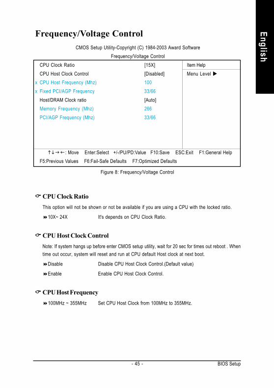
Frequency/Voltage Control
Figure 8: Frequency/Voltage Control
CMOS Setup Utility-Copyright (C) 1984-2003 Award SoftwareFrequency/Voltage Control
CPU Clock Ratio [15X] Item HelpCPU Host Clock Control [Disabled] Menu Level
x CPU Host Frequency (Mhz) 100x Fixed PCI/AGP Frequency 33/66
Host/DRAM Clock ratio [Auto]Memory Frequency (Mhz) 266PCI/AGP Frequency (Mhz) 33/66
: Move Enter:Select +/-/PU/PD:Value F10:Save ESC:Exit F1:General HelpF5:Previous Values F6:Fail-Safe Defaults F7:Optimized Defaults
CPU Clock RatioThis option will not be shown or not be available if you are using a CPU with the locked ratio.
10X~ 24X It's depends on CPU Clock Ratio.
CPU Host Clock ControlNote: If system hangs up before enter CMOS setup utility, wait for 20 sec for times out reboot . Whentime out occur, system will reset and run at CPU default Host clock at next boot.
Disable Disable CPU Host Clock Control.(Default value)
Enable Enable CPU Host Clock Control.
CPU Host Frequency100MHz ~ 355MHz Set CPU Host Clock from 100MHz to 355MHz.

- 46 -GA-8IR2003 Motherboard
Engl
ish Fixed Fixed Fixed Fixed Fixed PCI/AGP Divider
You can choose Disabled,PLL/40,PLL/32,PLL/24,PLL/20/PLL/16 mode to adjust PCI/AGPfrequency.
Host/DRAM Clock Ratio(Warning: wrong frequency may make system can't boot, clear CMOS to overcome wrongfrequency issue)
2.0 Memory Frequency = Host clock X 2.0.
2.66 Memory Frequency = Host clock X 2.66.
Auto Set Memory frequency by DRAM SPD data. (Default value)
Memory Frequency (Mhz)The values depend on CPU Host Frequency(Mhz) .
PCI/AGP Frequency (Mhz)Setup PCI/AGP frequency by adjusting CPU Host Frequency or PCI/AGP Divider item.

BIOS Setup
English
- 47 -
Top Performance
Top Performance
If you wish to maximize the performance of your system, set "Top Performance" as "Enabled".
Disabled Disable this function. (Default Value)
Enabled Enable Top Performance function.
"Top Performance" will increase H/W working speed. Different system configuration (both H/Wcomponent and OS) will effect the result. For example, the same H/W configuration might not runproperly with Windows XP, but works smoothly with Windows NT. Therefore, if your system is notperform enough, the reliability or stability problem will appear sometimes, and we will recommendyou disabling the option to avoid the problem as mentioned above.
Figure 9: Top Performance
CMOS Setup Utility-Copyright (C) 1984-2003 Award Software
Standard CMOS Features Top Performance
Advanced Chipset Features Load Fail-Safe Defaults
Integrated Peripherals Load Optimized Defaults
Power Management Setup Set Supervisor Password
PnP/PCI Configurations Set User Password
PC Health Status Save & Exit Setup
Frequency/Voltage Control Exit Without Saving
ESC:Quit :Select Item
F8: Q-Flash F10:Save & Exit Setup
Top Performance
Disabled...................[ ]Enabled................... [ ]
: Move ENTER: Accept
ESC: Abort

- 48 -GA-8IR2003 Motherboard
Engl
ish Load Fail-Safe Defaults
Load Fail-Safe DefaultsFail-Safe defaults contain the most appropriate values of the system parameters that allow mini-
mum system performance.
Figure 10: Load Fail-Safe Defaults
CMOS Setup Utility-Copyright (C) 1984-2003 Award Software
Standard CMOS Features Top Performance
Advanced Chipset Features Load Fail-Safe Defaults
Integrated Peripherals Load Optimized Defaults
Power Management Setup Set Supervisor Password
PnP/PCI Configurations Set User Password
PC Health Status Save & Exit Setup
Frequency/Voltage Control Exit Without Saving
ESC:Quit :Select Item
F8: Q-Flash F10:Save & Exit Setup
Load Fail-Safe Defaults
Load Fail-Safe Defaults (Y/N) ? N

BIOS Setup
English
- 49 -
Load Optimized Defaults
Load Optimized DefaultsSelecting this field loads the factory defaults for BIOS and Chipset Features which the system
automatically detects.
Figure 11: Load Optimized Defaults
CMOS Setup Utility-Copyright (C) 1984-2003 Award Software
Standard CMOS Features Top Performance
Advanced BIOS Features Load Fail-Safe Defaults
Integrated Peripherals Load Optimized Defaults
Power Management Setup Set Supervisor Password
PnP/PCI Configurations Set User Password
PC Health Status Save & Exit Setup
Frequency/Voltage Control Exit Without Saving
ESC:Quit :Select Item
F8: Q-Flash F10:Save & Exit Setup
Load Optimized Defaults
Load Optimized Defaults (Y/N) ? N

- 50 -GA-8IR2003 Motherboard
Engl
ish Set Supervisor/User Password
When you select this function, the following message will appear at the center of the screen toassist you in creating a password.
Type the password, up to eight characters, and press <Enter>. You will be asked to confirm thepassword. Type the password again and press <Enter>. You may also press <Esc> to abort theselection and not enter a password.
To disable password, just press <Enter> when you are prompted to enter password. A message"PASSWORD DISABLED" will appear to confirm the password being disabled. Once the password isdisabled, the system will boot and you can enter Setup freely.
The BIOS Setup program allows you to specify two separate passwords:SUPERVISOR PASSWORD and a USER PASSWORD. When disabled, anyone may access all
BIOS Setup program function. When enabled, the Supervisor password is required for entering the BIOSSetup program and having full configuration fields, the User password is required to access only basicitems.
If you select "System" at "Password Check" in Advance BIOS Features Menu, you will beprompted for the password every time the system is rebooted or any time you try to enter Setup Menu.
If you select "Setup" at "Password Check" in Advance BIOS Features Menu, you will be promptedonly when you try to enter Setup.
Figure 12: Password Setting
CMOS Setup Utility-Copyright (C) 1984-2003 Award Software
Standard CMOS Features Top Performance
Advanced BIOS Features Load Fail-Safe Defaults
Integrated Peripherals Load Optimized Defaults
Power Management Setup Set Supervisor Password
PnP/PCI Configurations Set User Password
PC Health Status Save & Exit Setup
Frequency/Voltage Control Exit Without Saving
ESC:Quit :Select Item
F8: Q-Flash F10:Save & Exit Setup
Change/Set/Disable Password
Enter Password:

BIOS Setup
English
- 51 -
Save & Exit Setup
Type "Y" will quit the Setup Utility and save the user setup value to RTC CMOS.Type "N" will return to Setup Utility.
Figure 13: Save & Exit Setup
CMOS Setup Utility-Copyright (C) 1984-2003 Award Software
Standard CMOS Features Top Performance
Advanced BIOS Features Load Fail-Safe Defaults
Integrated Peripherals Load Optimized Defaults
Power Management Setup Set Supervisor Password
PnP/PCI Configurations Set User Password
PC Health Status Save & Exit Setup
Frequency/Voltage Control Exit Without Saving
ESC:Quit :Select Item
F8: Q-Flash F10:Save & Exit Setup
Save Data to CMOS
Save to CMOS and EXIT (Y/N) ? Y

- 52 -GA-8IR2003 Motherboard
Engl
ish Exit Without Saving
Type "Y" will quit the Setup Utility without saving to RTC CMOS.Type "N" will return to Setup Utility.
Figure 14: Exit Without Saving
CMOS Setup Utility-Copyright (C) 1984-2003 Award Software
Standard CMOS Features Top Performance
Advanced BIOS Features Load Fail-Safe Defaults
Integrated Peripherals Load Optimized Defaults
Power Management Setup Set Supervisor Password
PnP/PCI Configurations Set User Password
PC Health Status Save & Exit Setup
Frequency/Voltage Control Exit Without Saving
ESC:Quit :Select Item
F8: Q-Flash F10:Save & Exit Setup
Abandon all Data
Quit Without Saving (Y/N) ? N

Technical Reference- 53 -
English
Revision HistoryChapter 4 Technical ReferenceBlock Diagram
Pentium 4Socket 478B
CPU
Intel82845
ITE8712
AC97CODEC
IntelICH 2
CPUCLK+/- (100/133* MHz)
System Bus400/533 MHz
DDR200/266MHz
MCH66 (66MHz)MCHCLK+/- (100/133* MHz)
66 MHz33 MHz14.318 MHz
48 MHz
48 MHz
LPC BUS
AGP 4X
AGPCLK(66MHz)
5 PCI
PCICLK(33MHz)
AC97 Link
MIC
LINE
-INLI
NE-O
UT
4 USBPorts
ATA33/66/100IDE Channels
Game Port
Floppy
LPT Port
PS/2 KB/Mouse
COM Ports
BIOS
"*" Auto detect and optimized setting for Pentium® 4 processor.
ICS950223
MCH66 (66MHz)CPUCLK+/- (100/133* MHz)AGPCLK (66MHz)MCHCLK+/- (100/133* MHz)ICH3V66 (66MHz)
PCICLK (33MHz)USBCLK (48MHz)
14.318 MHz33 MHz

- 54 -GA-8IR2003 Motherboard
Engl
ish @BIOS™ Introduction
Gigabyte announces @BIOS™
Windows BIOS live update utilityHave you ever updated BIOS by yourself? Or likemany other people, you just know what BIOS is,but always hesitate to update it? Because you thinkupdating newest BIOS is unnecessary and actuallyyou don't know how to update it.
Maybe not like others, you are very experienced in BIOS updating and spend quite a lot of timeto do it. But of course you don’t like to do it too much. First, download different BIOS from website andthen switch the operating system to DOS mode. Secondly, use different flash utility to update BIOS.The above process is not a interesting job. Besides, always be carefully to store the BIOS source codecorrectly in your disks as if you update the wrong BIOS, it will be a nightmare.
Certainly, you wonder why motherboard vendors could not just do something right to save yourtime and effort and save you from the lousy BIOS updating work? Here it comes! Now Gigabyteannounces @BIOS—the first Windows BIOS live update utility. This is a smart BIOS update software.It could help you to download the BIOS from internetand update it. Not like the other BIOS updatesoftware, it's a Windows utility. With the help of "@BIOS", BIOS updating is no more than a click.
Besides, no matter which mainboard you are using, if it’s a Gigabyte's product*, @BIOS help youto maintain the BIOS. This utility could detect your correct mainboard model and help you to choose theBIOS accordingly. It then downloads the BIOS from the nearest Gigabyte ftp site automatically. Thereare several different choices; you could use "Internet Update" to download and update your BIOSdirectly. Or you may want to keep a backup for your current BIOS, just choose "Save Current BIOS"to save it first. You make a wise choice to use Gigabyte, and @BIOS update your BIOS smartly. Youare now worry free from updating wrong BIOS, and capable to maintain and manage your BIOSeasily. Again, Gigabyte's innovative product erects a milestone in mainboard industries.
For such a wonderful software, how much it costs? Impossible! It's free! Now, if you buy aGigabyte's motherboard, you could find this amazing software in the attached driver CD. But pleaseremember, connected to internet at first, then you could have a internet BIOS update from yourGigabyte @BIOS.

Technical Reference- 55 -
English
EasyTune™ 4 IntroductionGigabyte announces EasyTune™ 4Windows based Overclocking utilityEasyTune 4 carries on the heritage so as to pave the way for future generations.
Overclock might be one of the most common issuesin computer field. But have many users ever tried it?The answer is probably "no". Because "Overclock"is thought to be very difficult and includes a lot oftechnical know-how, sometimes "Overclock" iseven considered as special skills found only in someenthusiasts. But as to the experts in "Overclock",what's the truth? They may spend quite a lot of timeand money to study, try and use many different
hardware or BIOS tools to do "Overclock". And even with these technologies, they still learn that it'squite a risk because the safety and stability of an "Overclock" system is unknown. Now everythingis different because of a Windows based overclocking utility "EasyTune 4" --announced by Gigabyte.This windows based utility has totally changed the gaming rule of "Overclock". This is the firstwindows based overclocking utility is suitable for both normal and power users. Users can chooseeither "Easy Mode" or "Advanced Mode" for overclocking at their convenience. For users whochoose "Easy Mode", they just need to click "Auto Optimize" to have autoed and immediate CPUoverclocking. This software will then overdrive CPU speed automatically with the result being shownin the control panel. If users prefer "Overclock" by them, there is also another choice. Click "AdvancedMode" to enjoy "sport drive" class Overclocking user interface. "Advanced Mode", allows users tochange the system bus / AGP / Memory working frequency in small increments to get ultimate systemperformance. It operates in coordination with Gigabyte motherboards. Besides, it is different from othertraditional over-clocking methods, EasyTune 4 doesn't require users to change neither BIOS norhardware switch/ jumper setting; on the other hand, they can do "Overclock" at easy step . Therefore,this is a safer way for "Overclock" as nothing is changed on software or hardware. If user runsEasyTune 4 over system's limitation, the biggest lost is only to restart the computer again and the sideeffect is then well controlled. Moreover, if one well-performed system speed has been tested inEasyTune 4, user can "Save" this setting and "Load" it in next time. Obviously, Gigabyte EasyTune4 has already turned the "Overclock" technology toward to a newer generation. This wonderfulsoftware is now free bundled in Gigabyte motherboard attached in driver CD. Users may make a testdrive of "EasyTune 4" to find out more amazing features by themselves.*Some Gigabyte products are not fully supported by EasyTune 4. Please find the products supportedlist in the web site.*Any "Overclocking action" is at user's risk, Gigabyte Technology will not be responsible for anydamage or instability to your processor, motherboard, or any other components.

- 56 -GA-8IR2003 Motherboard
Engl
ish Flash BIOS Method Introduction
A. What is Q-Flash Utility?Q-Flash utility is a pre-O.S. BIOS flash utility enables users to update its BIOS within BIOS
mode, no more fooling around any OS.B. How to use Q-Flash?a. After power on the computer, pressing <Del> immediately during POST (Power On Self Test) it willallow you to enter AWARD BIOS CMOS SETUP, then press <F8> to enter Q-Flash utility.
CMOS Setup Utility-Copyright (C) 1984-2002 Award Software
Standard CMOS Features Load Fail-Safe Defaults
Advanced BIOS Features Load Optimized Defaults
Integrated Peripherals Set Supervisor Password
Power Management Setup Set User Password
PnP/PCI Configurations Save & Exit Setup
Frequency/Voltage Control Exit Without Saving
Top Performance
ESC:Quit :Select Item
F8: Q-Flash F10:Save & Exit Setup
Time, Date, Hard Disk Type...
Enter Q-Flash Utility (Y/N)? Y
b. Q-Flash Utility
Q-Flash Utility V3.07
Flash Type/Size : SST 49LF002A / 256KKeep DMI Data : Yes
Space Bar:Change ValueEnter: Run ESC: Reset / : Select Item
Load BIOS from FloppySave BIOS to Floppy
Method 1 : Q-Flash

Technical Reference- 57 -
English
Congratulation! You have completed the flashed and now can restart system.
Load BIOS From FloppyIn the A:drive, insert the "BIOS" diskette, then Press Enter to Run.
XXXX.XX 256K
Total Size: 1.39M Free Size: 1.14MF5: Refresh DEL: Delete ESC: Return Main
Press Enter to Run.
1 File(s) found
Are you sure to update BIOS?[Enter] to contiune Or [ESC] ot abort...
!! COPY BIOS Completed -Pass !!Please press any key to continue
Press Enter to Run.
Where XXXX.XX is name of the BIOS file.

- 58 -GA-8IR2003 Motherboard
Engl
ish
We use GA-7VTX motherboard and Flash841 BIOS flash utility as example.Please flash the BIOS according to the following procedures if you are now under the DOS mode.Flash BIOS Procedure:
STEP 1:(1) Please make sure you have set "Auto" for BIOS Feature Setup (BIOS Flash Protection).(2) Please make sure your system has installed the extraction utility such as winzip or pkunzip.
Firstly you have to install the extraction utility such as winzip or pkunzip for unzip the files. Both ofthese utilities are available on many shareware download pages like http://www.shareware.cnet.com
STEP 2: Make a DOS boot diskette. (See example: Windows 98 O.S.)Beware: Windows ME/2000 are not allowed to make a DOS boot diskette.(1) With an available floppy disk in the floppy drive. Please leave the diskette "UN-write protected" type.Double click the "My Computer" icon from Desktop, then click "3.5 diskette (A)" and right click to select"Format (M)"
BIOS Flash ProcedureMethod 2 : BIOS Flash Utility
Technical Reference- 59 -
English
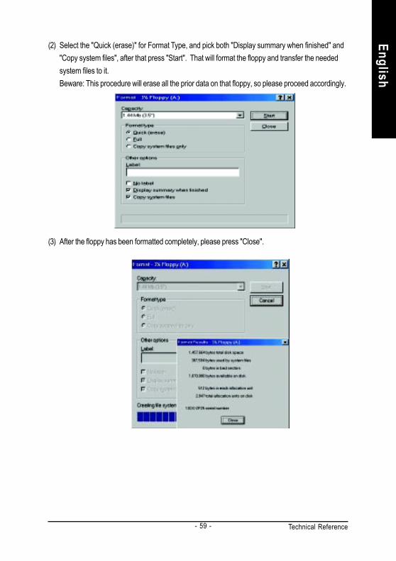
(2) Select the "Quick (erase)" for Format Type, and pick both "Display summary when finished" and"Copy system files", after that press "Start". That will format the floppy and transfer the neededsystem files to it.Beware: This procedure will erase all the prior data on that floppy, so please proceed accordingly.
(3) After the floppy has been formatted completely, please press "Close".

- 60 -GA-8IR2003 Motherboard
Engl
ish STEP 3: Download BIOS and BIOS utility program.
(1) Please go to Gigabyte website http://www.gigabyte.com.tw/index.html, and click "Support".
(2) From Support zone, click the "Motherboards BIOS & Drivers".

Technical Reference- 61 -
English
(3) We use GA-7VTX motherboard as example. Please select GA-7VTX by Model or Chipset optionalmenu to obtain BIOS flash files.
(4) Select an appropriate BIOS version (For example: F4), and click to download the file. It will pop upa file download screen, then select the "Open this file from its current location" and press "OK".

- 62 -GA-8IR2003 Motherboard
Engl
ish (5) At this time the screen shows the following picture, please click "Extract" button to unzip the files.
(6) Please extract the download files into the clean bootable floppy disk A mentioned in STEP 2, andpress "Extract".

Technical Reference- 63 -
English
STEP 4: Make sure the system will boot from the floppy disk.(1) Insert the floppy disk (contains bootable program and unzip file) into the floppy drive A. Then, restart
the system. The system will boot from the floppy disk. Please press <DEL> key to enter BIOS setupmain menu when system is boot up.
(2) Once you enter the BIOS setup utility, the main menu will appear on the screen. Use the arrows tohighlight the item "BIOS FEATURES SETUP".
7VTX F1Check System Health OKAMD-Athlon(tm)Processor-900MHzChecking NVRAM...262144KB
Wait...Press F1 to enter Dual BIOS Utility. Press ESC to quitPress any key to contiune
( C ) American Megatrends Inc.,63-0001-001199-00101111-071595-VIA_K7-GA7VTX1-F
American Release:09/16/99Megatrends AMIBIOS (C) 1999 American Megatrend
AMIBIOS SIMPLE SETUP UTILITY - VERSION 1.24b(C) 1999 American Megatrends, Inc. All Rights Reserved
STANDARD CMOS SETUP INTEGRATED PERIPHERALS
BIOS FEATURES SETUP HARDWARE MONITOR & MISC SETUP
CHIPSET FEATURES SETUP SUPERVISOR PASSWORD
POWER MANAGEMENT SETUP USER PASSWORD
PNP / PCI CONFIGURATION IDE HDD AUTO DETECTION
LOAD BIOS DEFAULTS SAVE & EXIT SETUP
LOAD SETUP DEFAULTS EXIT WITHOUT SAVING
ESC: Quit : Select Item (Shift)F2 : Change Color F5: Old Values
F6: Load BIOS Defaults F7: Load Setup Defaults F10:Save & Exit
Time, Date , Hard Disk Type…

- 64 -GA-8IR2003 Motherboard
Engl
ish (3) Press "Enter" to enter "BIOS FEATURES SETUP" menu. Use the arrows to highlight the item
"1st Boot Device", and then use the "Page Up" or "Page Down" keys to select "Floppy".
(4) Press "ESC" to go back to previous screen. Use the arrows to highlight the item "SAVE & EXITSETUP" then press "Enter". System will ask "SAVE to CMOS and EXIT (Y/N)?" Press "Y" and"Enter" keys to confirm. Now the system will reboot automatically, the new BIOS setting will betaken effect next boot-up.
AMIBIOS SETUP - BIOS FEATURES SETUP( C ) 2001 American Megatrends, Inc. All Rights Reserved
1st Boot Device : Floppy2nd Boot Device : IDE-03rd Boot Device : CDROMS.M.A.R.T. for Hard Disks : DisabledBootUp Num-Lock : On ESC: Quit : Select ItemFloppy Drive Seek : Disabled F1 : Help PU/PD/+/- : ModifyPassword Check : Setup F5 : Old Values (Shift)F2: Color
F6 : Load BIOS DefaultsF7 : Load Setup Defaults
AMIBIOS SIMPLE SETUP UTILITY - VERSION 1.24b(C) 2001 American Megatrends, Inc. All Rights Reserved
STANDARD CMOS SETUP INTEGRATED PERIPHERALS
BIOS FEATURES SETUP HARDWARE MONITOR & MISC SETUP
CHIPSET FEATURES SETUP SUPERVISOR PASSWORD
POWER MANAGEMENT SETUP USER PASSWORD
PNP / PCI CONFIGURATION IDE HDD AUTO DETECTION
LOAD BIOS DEFAULTS SAVE & EXIT SETUP
LOAD SETUP DEFAULTS EXIT WITHOUT SAVING
ESC: Quit : Select Item (Shift)F2 : Change Color F5: Old Values
F6: Load BIOS Defaults F7: Load Setup Defaults F10:Save & Exit
Save Data to CMOS & Exit SETUP
Save to CMOS and EXIT (Y/N)? Y

Technical Reference- 65 -
English
STEP 5: BIOS flashing.(1) After the system boot from floppy disk, type "A:\> dir/w" and press "Enter" to check the entire files
in floppy A. Then type the "BIOS flash utility" and "BIOS file" after A:\>. In this case you have totype "A:\> Flash841 7VTX.F4" and then press "Enter".
(2) Now screen appears the following Flash Utility main menu. Press "Enter", the highlighted item willlocate on the model name of the right-upper screen. Right after that, press "Enter" to start BIOS FlashUtility.
Starting Windows 98…
Microsoft(R) Windows98 © Copyright Microsoft Corp 1981-1999
A:\> dir/w Volume in drive A has no labelVolume Serial Number is 16EB-353DDirectory of A:\COMMAND.COM 7VTX.F4 FLASH841.EXE 3 file(s) 838,954 bytes 0 dir(s) 324,608 bytes free
A:\> Flash841 7VTX.F4

- 66 -GA-8IR2003 Motherboard
Engl
ish (3) It will pop up a screen and asks "Are you sure to flash the BIOS?" Press [Enter] to continue the
procedure, or press [ESC] to quit.Beware: Please do not turn off the system while you are upgrading BIOS. It will render your BIOScorrupted and system totally inoperative.
(4) The BIOS flash completed. Please press [ESC] to exit Flash Utility.
Are you sure to flash the BIOS?[Enter] to continue Or [Esc] to cancel?
EXIT?[Enter] to continue Or [Esc] to cancel?

Technical Reference- 67 -
English
STEP 6: Load BIOS defaults.Normally the system redetects all devices after BIOS has been upgraded. Therefore, we highlyrecommend reloading the BIOS defaults after BIOS has been upgraded. This important step resetseverything after the flash.
(1) Take out the floppy diskette from floppy drive, and then restart the system. The boot up screen willindicate your motherboard model and current BIOS version.
(2) Don't forget to press <DEL> key to enter BIOS setup again when system is boot up. Use the arrowsto highlight the item "LOAD SETUP DEFAULTS" then press "Enter". System will ask "Load SetupDefaults (Y/N)?" Press "Y" and "Enter" keys to confirm.
7VTX F4Check System Health OKAMD-Athlon(tm)Processor-900MHzChecking NVRAM...262144KB
Wait...Press F1 to enter Dual BIOS Utility. Press ESC to quitPress any key to contiune
( C ) American Megatrends Inc.,63-0001-001199-00101111-071595-VIA_K7-GA7VTX1-F
American Release:09/16/99Megatrends AMIBIOS (C) 1999 American Megatrend
AMIBIOS SIMPLE SETUP UTILITY - VERSION 1.24b(C) 2001 American Megatrends, Inc. All Rights Reserved
STANDARD CMOS SETUP INTEGRATED PERIPHERALS
BIOS FEATURES SETUP HARDWARE MONITOR & MISC SETUP
CHIPSET FEATURES SETUP SUPERVISOR PASSWORD
POWER MANAGEMENT SETUP USER PASSWORD
PNP / PCI CONFIGURATION IDE HDD AUTO DETECTION
LOAD BIOS DEFAULTS SAVE & EXIT SETUP
LOAD SETUP DEFAULTS EXIT WITHOUT SAVING
ESC: Quit : Select Item (Shift)F2 : Change Color F5: Old Values
F6: Load BIOS Defaults F7: Load Setup Defaults F10:Save & Exit
Load Setup Defaults
Load Setup Defaults? (Y/N)?N

- 68 -GA-8IR2003 Motherboard
Engl
ish (3) Use the arrows to highlight the item "SAVE & EXIT SETUP" and press "Enter". System will ask
"SAVE to CMOS and EXIT (Y/N)?" Press "Y" and "Enter" keys to confirm. Now the system willreboot automatically, the new BIOS setting will be taken effect next boot-up.
(4) Congratulate you have accomplished the BIOS flash procedure.
AMIBIOS SIMPLE SETUP UTILITY - VERSION 1.24b(C) 2001 American Megatrends, Inc. All Rights Reserved
STANDARD CMOS SETUP INTEGRATED PERIPHERALS
BIOS FEATURES SETUP HARDWARE MONITOR & MISC SETUP
CHIPSET FEATURES SETUP SUPERVISOR PASSWORD
POWER MANAGEMENT SETUP USER PASSWORD
PNP / PCI CONFIGURATION IDE HDD AUTO DETECTION
LOAD BIOS DEFAULTS SAVE & EXIT SETUP
LOAD SETUP DEFAULTS EXIT WITHOUT SAVING
ESC: Quit : Select Item (Shift)F2 : Change Color F5: Old Values
F6: Load BIOS Defaults F7: Load Setup Defaults F10:Save & Exit
Save Data to CMOS & Exit SETUP
Save to CMOS and EXIT (Y/N)? Y

Technical Reference- 69 -
English
Methods and steps: I. Update BIOS through Internet
a. Click "Internet Update" iconb. Click "Update New BIOS" iconc. Select @BIOS™ severd. Select the exact model name on your motherboard.e. System will automatically download and update the BIOS.
Method 3 : @BIOS Utility
(3)
(1)
3.Click " ".
(4)
(2)
1. Click "@BIOS" item.
Press here. 2. Click Start/ All Programs/ GIGABYTE/ @BIOS.
4. Please select @BIOS sever site, then Click "OK".
Click here
If you don't have DOS boot disk, we recommend that you used Gigabyte @BIOS™ program to flashBIOS.

- 70 -GA-8IR2003 Motherboard
Engl
ish II. Update BIOS NOT through Internet:
a. Do not click "Internet Update" iconb. Click "Update New BIOS"c. Please select "All Files" in dialog box while opening the old file.d. Please search for BIOS unzip file, downloading from internet or any other methods (such as:
8IR2003.E1).e. Complete update process following the instruction.
III. Save BIOSIn the very beginning, there is "Save Current BIOS" icon shown in dialog box. It means to save the
current BIOS version.
IV. Check out supported motherboard and Flash ROM:In the very beginning, there is "About this program" icon shown in dialog box. It can help you check
out which kind of motherboard and which brand of Flash ROM are supported.Note:
a. In method I, if it shows two or more motherboard's model names to be selected, please makesure your motherboard's model name again. Selecting wrong model name will cause thesystem unbooted.
b. In method II, be sure that motherboard's model name in BIOS unzip file are the same as yourmotherboard's. Otherwise, your system won't boot.
c. In method I, if the BIOS file you need cannot be found in @BIOS™ server, please go ontoGigabyte's web site for downloading and updating it according to method II.
d. Please note that any interruption during updating will cause system unbooted

Technical Reference- 71 -
English
2- / 4- / 6-Channel Audio Function Introuction
Stereo Speakers Connection and Settings:
We recommend that you use the speaker with amplifier to acqiire the best sound effect if the stereooutput is applied.
STEP 1:Connect the stereo speakers or earphone to "LineOut".
The installation of Windows 98SE/2K/ME/XP is very simple. Please follow next step to install thefunction!
Line Out
STEP 3:Select "Speaker Configuration", and choose the"2 channels for stereo speakers out put".
STEP 2 :After installation of the audio driver, you'll find an
icon on the taskbar's status area. Click theaudio icon "Sound Effect" from the windows tray atthe bottom of the screen.
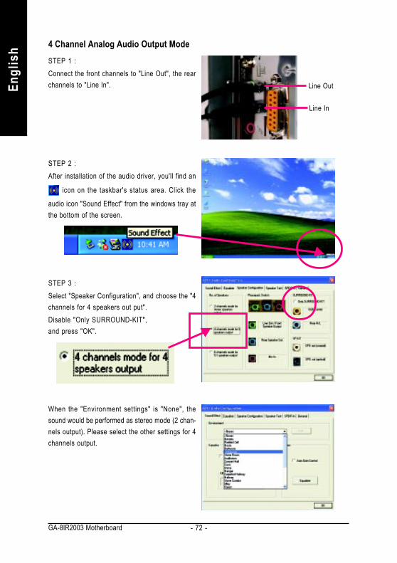
- 72 -GA-8IR2003 Motherboard
Engl
ish 4 Channel Analog Audio Output Mode
STEP 1 :Connect the front channels to "Line Out", the rearchannels to "Line In".
STEP 2 :After installation of the audio driver, you'll find an
icon on the taskbar's status area. Click the
audio icon "Sound Effect" from the windows tray atthe bottom of the screen.
Line Out
Line In
STEP 3 :Select "Speaker Configuration", and choose the "4channels for 4 speakers out put".Disable "Only SURROUND-KIT",and press "OK".
When the "Environment settings" is "None", thesound would be performed as stereo mode (2 chan-nels output). Please select the other settings for 4channels output.

Technical Reference- 73 -
English
Use the back audio panel to connect the audiooutput without any additional module.STEP 1 :Connect the front channels to "Line Out", the rearchannels to "Line In", and the Center/Subwooferchannels to "MIC In".
Basic 6 Channel Analog Audio Output Mode
Line Out
Line In
MIC In
STEP 2 :After installation of the audio driver, you'll find an
icon on the taskbar's status area. Click the
audio icon "Sound Effect" from the windows tray atthe bottom of the screen.
STEP 3 :Select "Speaker Configuration", and choose the"6 channels for 5.1 speakers out put".Disable "Only SURROUND-KIT" and pess "OK".

- 74 -GA-8IR2003 Motherboard
Engl
ish Advanced 6 Channel Analog Audio Output Mode (using Audio Combo Kit,
Optional Device):(Audio Combo Kit provides SPDIF output port : optical & coaxis and SURROUND-KIT : Rear R/L &Center/subwoofer)
STEP 1 :Insert the "Audio Combo Kit" in the back of thecase, and fix it with the screw.
SURROUND-KIT access analog output to rearchannels and Center/Subwoofer channels. It is thebest solution if you need 6 channel output, Line Inand MIC at the same time. "SURROUND-KIT" isincluded in the GIGABYTE unique "Audio ComboKit" as picture.
STEP 2 :Connect the "SURROUND-KIT" to SUR_CEN onthe M/B.

Technical Reference- 75 -
English
STEP 4 :Click the audio icon "Sound Effect" from the win-dows tray at the bottom of the screen.
STEP 3 :Connect the front channels to back audio panel's"Line Out", the rear channels to SURROUND-KIT'sREAR R/L, and the Center/Subwoofer channels toSURROUND-KIT's SUB CENTER.
STEP 5 :Select "Speaker Configuration", and choose the"6 channels for 5.1 speakers out put".Enable "Only SURROUND-KIT" and press "OK".
When the "Environment settings" is "None", thesound would be performed as stereo mode (2 chan-nels output). Please select the other settings for 6channels output.
Basic & Advanced 6 Channel Analog Audio Output Mode Notes:

- 76 -GA-8IR2003 Motherboard
Engl
ish SPDIF Output Device (Optional Device)
A "S/PDIF output" device is available on themotherboard. Cable with rear bracket is providedand could link to the "S/PDIF output" connector (Aspicture.) For the further linkage to decoder, rearbracket provides coaxial cable and Fiber connect-ing port.
3. Connect co-axial or optical output to the AC3 decoder.
1. Connect the SPDIF output device to the rear bracket of PC, and fix it with screw.
2. Connect SPDIF wire to the motherboard.

Appendix- 77 -
English
Revision HistoryChapter 5 Appendix
Pictures below are shown in Windows XP (IUCD ver 2.22)Insert the driver CD-title that came with your motherboard into your CD-ROM drive, thedriver CD-title will auto start and show the installation guide. If not, please double clickthe CD-ROM device icon in "My computer", and execute the setup.exe.
INSTALL CHIPSET DRIVER
Install Drivers
This page shows the drivers that need to be installed for the system. Click each item to install thedriver manually or switch to the to install the drivers automatically.
The "Xpress Install" uses the"Click and Forget" technology to install the drivers automatically. Justselect the drivers you want then click the "GO" button. The will finish the installation for youautomatically.
We recommend that you install all components in the list.
Massage: Some device drivers will restartyour system automatically. After restartingyour system the "Xpress Install" willcontinue to install other drivers.

- 78 -GA-8IR2003 Motherboard
Engl
ish
Intel Chipset Software Installation UtilityTell the operating system how the chipset components will be configuredIntel Application AcceleratorDesigned to improve performance of the storage sub-system and overall system performanceUSB Patch for WinXPThis patch driver can help you to resolve the USB device wake up S3 hang up issue in XPRealTek ALC101A/201A/202/650 AC97 Codec DriverFor Intel® ICH/ICH2/ICH4 AC97 audio
Item Description
Driver install finished !You have to reboot system !

Appendix- 79 -
English
SOFTWARE APPLICATIONThis page reveals the value-added software developed by Gigabyte and its worldwide partners.
Gigabyte Windows Utilities Manager (GWUM)This utility can integrate the Gigabyte's applications in the system trayGigabyte Management Tool (GMT)A useful tool which can manage the computer via the networkEasyTune 4Powerful utility that integrates the overclocking and hardware monitoring functionsDMI ViewerWindows based utility which is used to browse the DMI/SMBIOS information of the systemFace-WizardNew utility for adding BIOS logo@BIOSGigabyte windows flash BIOS utilityAcrobat e-BookUseful utility from AdobeAcrobat ReaderPopular utility from Adobe for reading .PDF file format documentsNorton Internet Security (NIS)Integrated utility which includes anti-virus, ads, etc.

- 80 -GA-8IR2003 Motherboard
Engl
ish SOFTWARE INFORMATION
This page list the contects of softwares and drivers in this CD title.
HARDWARE INFORMATIONThis page lists all device you have for this motherboard.
CONTACT USPlease see the last page for details.

Appendix- 81 -
English
EasyTune 4 Utilities InstallationPowerful utility that integrates the overclocking and hardware monitoring functions
(1) (2)
(4)
1. Click "EasyTune4" item. 2. Click "Next".
(3)
(6)(5)
3. Click "Finish" to restart computer.
4. Right Click the icon to start"EasyTune 4".
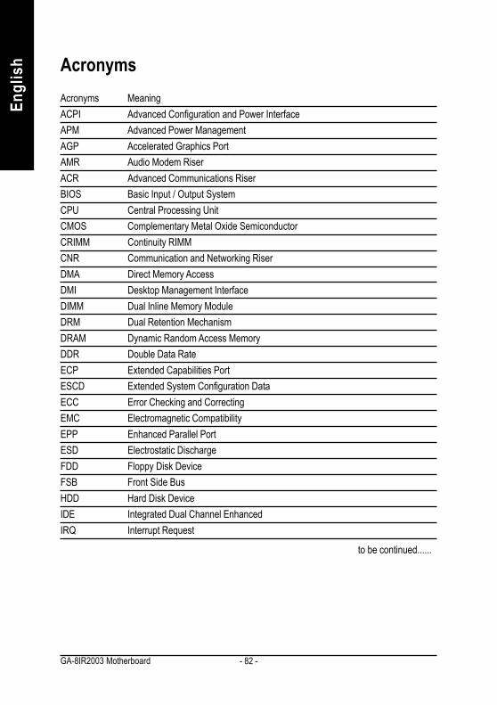
- 82 -GA-8IR2003 Motherboard
Engl
ish
Acronyms MeaningACPI Advanced Configuration and Power InterfaceAPM Advanced Power ManagementAGP Accelerated Graphics PortAMR Audio Modem RiserACR Advanced Communications RiserBIOS Basic Input / Output SystemCPU Central Processing UnitCMOS Complementary Metal Oxide SemiconductorCRIMM Continuity RIMMCNR Communication and Networking RiserDMA Direct Memory AccessDMI Desktop Management InterfaceDIMM Dual Inline Memory ModuleDRM Dual Retention MechanismDRAM Dynamic Random Access MemoryDDR Double Data RateECP Extended Capabilities PortESCD Extended System Configuration DataECC Error Checking and CorrectingEMC Electromagnetic CompatibilityEPP Enhanced Parallel PortESD Electrostatic DischargeFDD Floppy Disk DeviceFSB Front Side BusHDD Hard Disk DeviceIDE Integrated Dual Channel EnhancedIRQ Interrupt Request
to be continued......
Acronyms

Appendix- 83 -
English
Acronyms MeaningIOAPIC Input Output Advanced Programmable Input ControllerISA Industry Standard ArchitectureLAN Local Area NetworkI/O Input / OutputLBA Logical Block AddressingLED Light Emitting DiodeMHz MegahertzMIDI Musical Instrument Digital InterfaceMTH Memory Translator HubMPT Memory Protocol TranslatorNIC Network Interface CardOS Operating SystemOEM Original Equipment ManufacturerPAC PCI A.G.P. ControllerPOST Power-On Self TestPCI Peripheral Component InterconnectRIMM Rambus in-line Memory ModuleSCI Special Circumstance InstructionsSECC Single Edge Contact CartridgeSRAM Static Random Access Memory
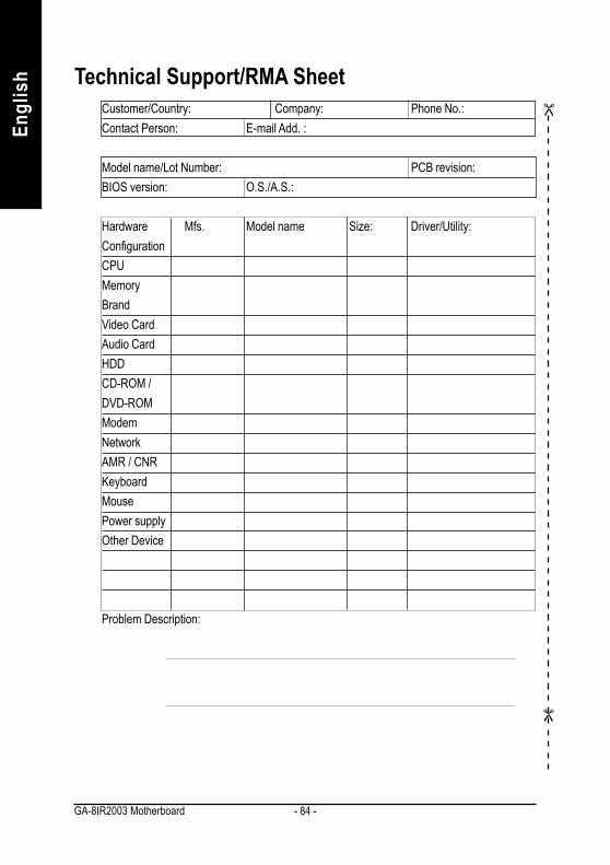
- 84 -GA-8IR2003 Motherboard
Engl
ish Technical Support/RMA Sheet
Customer/Country: Company: Phone No.:Contact Person: E-mail Add. :
Model name/Lot Number: PCB revision:BIOS version: O.S./A.S.:
Hardware Mfs. Model name Size: Driver/Utility:ConfigurationCPUMemoryBrandVideo CardAudio CardHDDCD-ROM /DVD-ROMModemNetworkAMR / CNRKeyboardMousePower supplyOther Device
Problem Description:

Appendix- 85 -
English
TroubleshootingIf you encounter any trouble during boot up, please follow the troubleshootingprocedures.
Turn off the power and unplug the AC power cable, then removeall of the add-on cards and cables from motherboard.
START
Failure has been excluded.
YesPlease make sure motherboard & chassis are not short ?
No
A
Please make sure all jumper settings (such as CPU systembus speed, frequency ratio, voltage and etc) are set properly.
Failure has been excluded.
Check if the CPU cooling fan attached to CPU properly. lsCPU cooling fan power connected to CPU_FAN properly?
Plug the CPUcooling fan powerin the CPU fanconnector. Plugin the AC powerconnector.
Check if the memory install properly into the DIMM slot.
Yes
No
Yes
Insert and pushthe memorymodule verticallyinto the DIMMslot.
Insert the VGA card. Then plug in ATX power cable andturn on the system.
No
No
Yes
Failure has been excluded.
Failure has been excluded.
Please isolatethe short pin.
Make sure thejumper settingare correct.

- 86 -GA-8IR2003 Motherboard
Engl
ish A
Failure has been excluded.Yes
No
Yes
No
Failure has been excluded.
Failure has been excluded.
Yes
Reinstall Windows OS, and reinstall add-on cards andcables. Then try to reboot the system. Failure has been excluded.
Yes
END
If the above procedure unable to solve your problem, please contact with your local retailer or nationaldistributor for help. Or, you could submit your question to the service mail via Gigabyte website technicalsupport zone (http://www.gigabyte.com.tw). The appropriate response will be provided ASAP.
Is memory LED on and CPU fan running?
The problem couldbe caused bypower supply,CPU, memory orCPU/memorysocket itself.
Check if there is display.Perhaps your VGAcard / VGA slot ormonitor is defective.
Turn off the system. Reboot after keyboard and mousehave been plugged in.
Check if keyboard is working properly.
It is possible thatyour keyboard orkeyboard connectoris defective.
Press <Del> to enter BIOS setup. Choose "LoadOptimized Defaults" and save then exit setup.
Turn off the system and re-connect the IDE cable.Check if the system can reboot successfully.
The problem wasprobably caused bythe IDE device /connector or cable.
No
No

- 87 -
English
Memo

- 88 -GA-8IR2003 Motherboard
Engl
ish

- 89 -
English
Memo

- 90 -GA-8IR2003 Motherboard
Engl
ish

- 91 -
English
Memo

- 92 -GA-8IR2003 Motherboard
Engl
ish
TaiwanGigabyte Technology Co., Ltd.Address: No.6, Bau Chiang Road, Hsin-Tien, TaipeiHsien, Taiwan, R.O.C.TEL: 886 (2) 8912-4888 (50 lines)FAX: 886 (2) 8912-4004E-mail:[email protected] Address: http://www.gigabyte.com.tw
USAG.B.T. INC.Address: 17358 Railroad St, City of Industry, CA91748.Tel: 1 (626) 854-9338Fax: 1 (626) 854-9339E-mail:[email protected] [email protected] Address: www.giga-byte.com
GermanyG.B.T. Technology Trading GmbHTel: 49-40-2533040Fax: 49-40-25492343 (Sales)Tel: 49-01803-428468 (Tech.)Fax: 49-01803-428329 (Tech.)E-mail:[email protected] Address: www.gigabyte.de
JAPAN/Nippon Giga-Byte CorporationFax: 81-3-5791-5439Web Address: www.gigabyte.co.jp
U.KG.B.T. TECH. CO. LTD.Tel: 44-1908-362700Fax: 44-1908-362709E-mail:[email protected] Address: www.gbt-tech.co.uk
The NetherlandsGiga-Byte Technology B.V.Address: Postbus 1385, 5602 BJ, Eindhoven, TheNetherlandsTel: +31 40 290 2088Fax: +31 40 290 2089E-mail:[email protected] Address: http://www.giga-byte.nl
ChinaShanghai OfficeTel: 86-21-64737410Fax: 86-21-64453227Web Address: www.gigabyte.com.cnGuangZhou OfficeTel: 86-20-87586273Fax: 86-20-87544306Web Address: www.gigabyte.com.cnBeijing OfficeTel: 86-10-8285605486-10-8285606486-10-82856094Fax: 86-10-82856575Web Address: www.gigabyte.com.cnE-mail:[email protected] OfficeTel: 86-28-85236930Fax: 86-28-85256822Web Address: www.gigabyte.com.cn
Contact us via the information in this page all over the world.
CONTACT US