mos 2.0 - modeling the next revolutionary mission operations
TRANSCRIPT
1
MOS 2.0 - Modeling The Next Revolutionary Mission Operations System
Christopher L. Delp, Duane Bindschadler, Ryan Wollaeger, Carlos Carrion, Michelle McCullar, Maddalena Jackson, Marc Sarrel, Louise Anderson, and Doris Lam
Jet Propulsion Laboratory, California Institute of Technology 4800 Oak Grove Drive Pasadena, CA 91109
818-354-0858 {Christopher.L.Delp,Duane.L.Bindschadler}@jpl.nasa.gov
Abstract—Designed and implemented in the 1980's, the Advanced Multi-Mission Operations System (AMMOS) was a breakthrough for deep-space NASA missions, enabling significant reductions in the cost and risk of implementing ground systems. By designing a framework for use across multiple missions and adaptability to specific mission needs, AMMOS developers created a set of applications that have operated dozens of deep-space robotic missions over the past 30 years. We seek to leverage advances in technology and practice of architecting and systems engineering, using model-based approaches to update the AMMOS. We therefore revisit fundamental aspects of the AMMOS, resulting in a major update to the Mission Operations System (MOS): MOS 2.0. This update will ensure that the MOS can support an increasing range of mission types, (such as orbiters, landers, rovers, penetrators and balloons), and that the operations systems for deep-space robotic missions can reap the benefits of an iterative multi-mission framework.12
This paper reports on the first phase of this major update. Here we describe the methods and formal semantics used to address MOS 2.0 architecture and some early results. Early benefits of this approach include improved stakeholder input and buy-in, the ability to articulate and focus effort on key, system-wide principles, and efficiency gains obtained by use of well-architected design patterns and the use of models to improve the quality of documentation and decrease the effort required to produce and maintain it. We find that such methods facilitate reasoning, simulation, analysis on the system design in terms of design impacts, generation of products (e.g., project-review and software-delivery products), and use of formal process descriptions to enable goal-based operations. This initial phase yields a forward-looking and principled MOS 2.0 architectural vision, which considers both the mission-specific context and long-term system sustainability.
TABLE OF CONTENTS
1. INTRODUCTION ................................................................. 1 2. MOS 2.0 ARCHITECTURE PRINCIPLES ............................ 2 3. ARCHITECTURAL CHARACTERIZATION OF TODAY’S
AMMOS .............................................................................. 3
1 978-1-4244-7351-9/11/$26.00 ©2011 IEEE.
2 IEEEAC paper #1512, Version 2, Updated Jan. 10, 2011
4. ARCHITECTING MOS 2.0 ................................................ 6 5. INITIAL RESULTS ........................................................... 11 6. ANTICIPATED RESULTS AND FUTURE PLANS ............... 13 ACKNOWLEDGEMENTS. ..................................................... 13 REFERENCES ...................................................................... 13 BIOGRAPHY ....................................................................... 14
1. INTRODUCTION
The original concept and much of the architecture of the Advanced Multi-Mission Operations System (AMMOS) predate the World Wide Web and the ensuing distributed, federated information-centric systems and applications. Ground systems for space missions in the 1980s were precursors to the large information systems of today. They were large and complex, and depended upon transfer of significant volumes of key information to support human decision-making. They required specialized computing platforms and networks to support (at the time) extreme demands on processing power, data transfer speeds and data volumes. The widespread adoption of the World-Wide Web, the Moore's Law growth in processing power and high performance networks have invited (even demanded) corporate investment in use of computing-intensive distributed information systems to perform business processes that vastly outweigh any investments NASA has made over the past two decades. We would be shortsighted not to leverage such advances.
Fusion of the advances in information systems with the advances in deep space mission operations requires a thoughtful approach that includes revisiting the fundamental architecture of the MOS. The Internet revolution has been deeply and broadly disruptive; piecemeal additions of such technologies have a high likelihood of failures, and even if adopted may not bring the expected results (e.g., lower costs). Piecework solutions have been applied, in some cases with perceived significant gains in efficiency. However, recent development efforts in AMMOS, or more generally to deep-space mission operations, have arguably resulted in no better than marginal gains. A comprehensive, architectural approach is thus necessary if we desire to take proper advantage of newer technologies. Moreover, we recognize that the disciplines of systems architecting and systems engineering have evolved and improved, and can confer significant advantages.

2
This paper reports on results of the first phase of a multi-year Operations (Ops) Revitalization Initiative [1,2]. The purpose of the initiative is to revitalize multimission operations capabilities of the AMMOS, with the eventual goal of a producing a next-generation mission operations system - MOS 2.0. The first phase of this work focuses on the MOS 2.0 architecting effort performed by the Ops Revitalization team, using a unique application of Enterprise Architecting and Model Based Systems Engineering (MBSE) techniques. We have adopted an approach to date in architecting, designing and implementing MOS 2.0 that:
(1) Provides a forward-looking principled architectural vision;
(2) Is driven by stakeholder engagement and collabora-tion;
(3) Insists on a disciplined approach that is rigorous, flexible, and based on broadly accepted standards; and
(4) Considers both the mission-specific context (project lifecycle) and long-term (multiple project lifecycles) sustainability of the system.
This paper first describes the fundamentals of Mission Operations Systems in terms of some of the key architectural principles and concepts. In particular these include identification of the MOS as:
A control system tasked with achievement of mission and science goals and managing mission resources, closing the loop on goals and resource management.
A system that supports a rapid prototyping mission development approach called "develop with what you fly with," which spans the mission development life-cycle.
A set of mission-adaptable, composable services that support the above principles and minimize the necessity (and incentive) for missions to “reinvent the wheel.”
We then describe results of modeling and analysis work done to characterize the current state of AMMOS. This effort was performed to determine how AMMOS abides by the key principles. Additionally this analysis addresses some issues expressed by stakeholders who adapt and operate AMMOS for missions. An overview of some key areas and results are described to provide an understanding of the challenges facing Ops Revitalization in the design and implementation of MOS 2.0. We then describe the architecting work to date and how it addresses some of the issues.
Finally, this paper describes the application of architecting and modeling techniques with focus on stakeholder driven process and formal systems modeling of products. Some flight projects have already adopted such products. By
infusing key aspects of our approach into flight projects, one is able to demonstrate the worth of this effort and increase the likelihood of stakeholder acceptance and validate the accuracy of the architecture.
2. MOS 2.0 ARCHITECTURE PRINCIPLES
A critical aspect of the Ops Revitalization effort was to establish the fundamentals of what a Mission Operations System “is” and “does.” To achieve this, Ops Revitalization begins with establishing the architectural principles for an MOS. These architectural principles become the foundation upon which MOS Architectures can be evaluated and a guiding light for architectural decisions. This is different from the concept of requirements in that principles guide, but do not necessarily direct or specify.
We view a modern MOS as a system that uses information from various models and simulations in conjunction with information from a flight system to pilot the mission through the successful acquisition of scientific and programmatic information. In fact, the MOS’ only products are information. It follows that the Mission Operation System is fundamentally a control system responsible for achievement of science and programmatic goals and management of mission resources. The MOS provides command and control function for the operation and management of flight system and flight-ground communications resources.
Our first architectural principle is that of closed-loop control. For an MOS to function as a control system it must be capable of closing the loop on specified objectives and states, that is, providing analysis to enable reconciliation between predicted and observed states and objectives. This principle touches every aspect of mission operations and is a motivation for all the other principles. If the MOS fails to properly control its flight system, the mission can be lost. Conversely, flying and roving in deep space exploration is expensive and among the most difficult human endeavors. Deep Space Operations requires efficient precision command and control capabilities on the ground. A key aspect of MOS is also that it includes the human element as part of the system definition. This means that humans are at some level always in the control loop.
The second principle for MOS 2.0 is to "develop with what you fly with." This principle prescribes that the MOS used to operate the mission should be the same system that is used to develop the mission. This means the multi-mission MOS serves as a platform that includes sufficient capability (in the form of models and software) to begin developing the Mission with a working, prototype MOS. Such an idea calls for a MOS capable of serving needs throughout a Project lifecycle: from conceptualization and formulation to operating in deep space. And because it must exist both before and after any specific Project, it must also support training and testing in a multi-mission sense without a specific mission.

3
In mission operations whatever models and simulations are built as part of developing, testing and operating the spacecraft become the ultimate source of truth once the spacecraft is launched. If these models lack integrity or fidelity necessary to control the mission, the mission risks some level of failure or reduced achievement. By developing the missions operations with the MOS that will fly it, repeated invention or multiple versions of models become unnecessary. Instead, multi-mission models undergo adaptation for any specific mission purpose and are centrally located so as to enable access as needed. As a byproduct, innovations from a specific mission can be incorporated into the multi-mission model assets. This also implies that the system is capable of reporting on itself in the form of performance, functionality, utilization of resources and other qualities.
This principle provides the most comprehensive multi-mission concept possible. Any system capable of realizing these concepts must be completely model-based. Only models can ensure the integrity of the information and systematic behavior required for moving from interesting ideas for science to a robust control system capable of achieving those goals.
Establishing these principles was a critical first step for the Ops Revitalization effort. They provide the fundamental foundation for:
Understanding strengths and weaknesses of the current implementation of AMMOS; and
Understanding how to architect MOS 2.0 in a next instance of AMMOS.
They benefited the architecting work to date by setting a benchmark for both understanding decisions and how to evaluate the work we have done so far.
3. ARCHITECTURAL CHARACTERIZATION OF
TODAY’S AMMOS
Using the MOS Principles, Ops Revitalization performed an “as-is” analysis and architectural characterization of the existing AMMOS. The objective was to determine how well AMMOS upholds the MOS Principles. This technique derives from enterprise architecture. Where AMMOS fits well with these principles, the next iteration should consolidate and build upon those solutions. Where AMMOS does not hold up, we can identify areas for improvement and expansion to better serve missions. The result provides focused direction for ongoing development of a true multi-mission framework.
The Ops Revitalization team evaluated the AMMOS by developing systems models using the SysML [3] and architectural views of the existing system [1] based on standards [4,5] to specifically understand AMMOS in the
context of the MOS Principles. An initial finding was that AMMOS lacks a truly multi-mission MOS component or concept at a system level. There exist descriptions or specifications of some multi-mission processes, interfaces, requirements and teams, but nothing exists in the way of design or deliverable products that address an integrated MOS. Thus the views we developed are only generally able to describe what is common in terms of the use of AMMOS by missions. Two key areas were evaluated:
Systems Concepts
Information Concepts
Current System Concept
Missions currently see the AMMOS primarily as a software toolkit - a collection of software tools made available for customization and use by each mission customer. Thus they do not generally look to the AMMOS to provide high-level concepts or guidance on what the AMMOS is or does as a system. Instead, each mission develops its own concept, frequently leaning heavily on analogy to familiar, previous missions. This practice has the tendency to persist architectural attributes across multiple missions, except for those that are highly undesirable or inefficient. These latter attributes are generally recognized and avoided by “lessons-learned” consideration and reviews by experienced experts. However, persistence of mediocre aspects is tolerated because (a) such aspects often go unevaluated and (b) the perceived risk of change is greater than any perceived benefits.
Ops Revitalization development of a common set of multi-mission scenarios in conjunction with stakeholders provided us with a set of common activities that characterize the conceptual architecture of AMMOS [2].
Analysis of these scenarios revealed that the AMMOS multi-mission conceptual architecture revolves around an uplink-downlink paradigm. The focus is on exchanging products with the spacecraft, with “uplink” or “planning and sequencing” (see Figure 1) representing the set of planning activities up to and including transmission of commands to the flight system, and “downlink” representing activities involved in capturing, processing, analyzing and storing data transmitted by the flight system to the ground. Absent at the conceptual level are first class concepts for state and functions that close the loop on state. These are left to the human operators to determine and track, supported by an ad hoc set of scripts and narrow-use software. Figure 1 is a typical depiction of the AMMOS uplink-downlink concept. Sub-system product flow is depicted (informally) in uplink and downlink contexts. AMMOS does not have a documented concept for how either the depicted components or the system as a whole provides a control function. Since no mission can actually fly open-loop, each mission using AMMOS must add these missing concepts into their adaptation of AMMOS.

4
Figure 1. Current AMMOS System Concept.
While concepts for MOS system-level verification, and mission-level validation (e.g., “Test As You Fly / Fly As You Test,”) do exist, AMMOS has no architectural concepts for the “develop with what you fly with” principle. A case study from the Spitzer mission provides a basic example of what this can mean to a mission.
One of NASA’s Great Observatories, the Spitzer telescope was levied with a requirement to spend at least 90% of the time observing (including instrument calibrations and slews to science targets). Despite this requirement and derived lower-level specifications, significant operational inefficiencies were present at launch and in early operations, centered on the management of onboard data storage and data return via the DSN [6,7].
The state variables representing the quantity of data in the onboard storage as a function of time had to be managed on the ground to ensure that there was enough storage for
subsequent science observations and engineering telemetry. Although a capability was developed prior to launch (including models, processes and procedures, and software) to manage this issue, it represented an “80% solution” and was not adequately tested. This is a common situation – testing time that requires the spacecraft itself or a high-fidelity testbed is at a premium during late stages of development. And priority may not be accorded to issues that are seen as having operational workarounds.
Spitzer was able to reach an effective, if ad-hoc solution during flight operations [6,7]. The costs of creating such a solution after launch (as opposed to much earlier in development) include lost science data, lost science observation opportunities, increased cost and workload on operations, and increased risk to the mission. AMMOS provided no means early in the lifecycle for identifying states that are to be controlled from the ground and no means to manage the resources they represented, nor did it

5
have any concept that included the type of simulation capabilities that could have identified and resolved these issues earlier in the Spitzer Project’s lifecycle.
This analysis identified the clear need for a Conceptual Architecture that fully supports the MOS principles. The benefits of this support would be to make explicit the control functions an MOS performs and how they are manifested throughout the lifecycle.
Current Models and Information Concept
The Ops Revitalization initiative also assessed the information concepts in AMMOS. Mission Operations depends greatly on models and information to perform the control function for the mission. AMMOS possesses a wide variety of modeling capabilities. These most commonly appear as mission-adaptable applications ranging from planning and sequencing to navigation to a few spacecraft analysis tools. These represent a key strength of the AMMOS.
In considering the MOS Principles of closed loop control and “develop with what you fly with,” one challenge is integrating these modeling capabilities into a system that supports and facilitates the conceptualization, development, deployment and operational control of the flight system.
Figure 2 depicts a sample information flow for uplink. This diagram reflects the current reality in AMMOS; it is focused on the file exchanges between software and people (teams). Interfaces are point-to-point connections and the relevant content is often copied across these individual transactions with no overarching concept of what transformations the information is undergoing or what the true state of the system is.
Analysis of the AMMOS information model revealed that common information concepts exist but are often obscured by unique information structures and a dearth of requirements, schemas, templates or standard definitions. The semantics of different structures are unclear and ambiguous ranging from spreadsheets, diagrams and specification documents to semantic models and files processed by software.
In order for MOS 2.0 to provide control capabilities across the life-cycle of the mission, an information model must be grounded in control-based concepts that:
Unify the multiply defined concepts from the various AMMOS models; and
Provide information models for products currently defined in an informal or ad-hoc fashion.
Figure 2. “As-Is” AMMOS Information Concept.

6
A unified information model would benefit missions and multi-mission development and maintenance. The benefits to AMMOS integration are:
Information repositories would replace the file-based persistence, facilitating configuration management and enabling new capabilities.
Content focused exchange mechanisms like messaging and resource based technologies would replace file based exchanges
Products would be verified and generated based on formally stated content rather than notional narratives and illustrations
Mission- and safety-critical aspects would be more easily identified and become the focus of automation
4. ARCHITECTING MOS 2.0
The Ops Revitalization Team used the characterization of the first revolutionary MOS - the AMMOS - as the driver for what and how to architect MOS 2.0. Three of the key areas addressed in the first phase of work are:
MOS 2.0 Conceptual Architecture
MOS 2.0 Systems and Services Architecture
MOS 2.0 Information Architecture
Each of these areas focused on the AMMOS “as-is” characterization and collaboration with stakeholders as the basis for decision-making as guided by the MOS Architecture principles. We also considered cutting edge technology and techniques from work being done to advance mission operations according to our principles. Two such efforts are the Mission Data System effort [8,9] and development and applications of the Automated Scheduling and Planning Environment (ASPEN) [10,11]. Both of these efforts have developed and demonstrated successful work in advanced Mission Operations that helped to inform our efforts and to validate our MOS Principles.
The separation of concern between the Mission Operations System and an MOS as an Organization within a Project is deliberate. It must be clear that the MOS 2.0 architecture does not account for the organizational aspects of the MOS. MOS 2.0 only defines the future state of the system as a specification of a product to be constructed. How a Flight Project, Mission or the Multi-Mission Ground Systems and Services organization (current developers of AMMOS) choose to organize around the specification is beyond the scope of this work.
MOS 2.0 Conceptual Architecture
The “as-is” analysis of AMMOS identified the need for a multi-mission system architectural concept that would:
Establish the system level closed loop control function.
Establish functional concepts for “develop with what you fly with.”
The Ops Revitalization team developed an end-to-end conceptual architecture to identify the functionality and information concepts that MOS 2.0 would require to abide by the MOS Principles. The Conceptual Architecture is specified using the SysML. The functional models express functions using SysML Activities, which provide a behavioral concept based on Petri nets complete with inputs and outputs. These models provide a system-level conceptual architecture that identifies the essential functional-flow across the lifecycle of mission development. This includes inputs and outputs for each function and the information concepts on those inputs and outputs.
Figure 3. MOS 2.0 Interaction Pattern for external interfaces. This general pattern is specialized for each interface with an external entity (Flight System, DSN, science data archive…).
At the heart of these concepts are two architectural patterns. The first pattern (Figure 3) identifies the fact that, as a control system that must serve or collaborate with other systems, the MOS 2.0 must interact with external systems in an accountable way. These are typically external exchanges of planning products and measurements with systems such as the DSN or the Flight System.
The second pattern provides the fundamental concept for any MOS. Figure 4 illustrates the essential functionality of Planning, Execution, and Analysis, and the flow of planned, predicted, observed, and reconciled information. This pattern provides an explicit functional specification for how any deep space MOS ought to behave. Models that follow this pattern still permit views that show only uplink or only downlink; the key addition is the (closed) prediction–reconciliation loop. This loop explicitly ensures that any of the three functions (Plan, Execute, Analyze) of an MOS require the other two, given the input-output dependencies.
With these essential patterns, we may build a conceptual architecture for MOS 2.0 that is consistent with the principle of control with explicit control loops and accountable exchanges with external systems.

7
Figure 4. MOS 2.0 Control Loop Pattern. This represents the central concept of the MOS as a closed-loop control system that includes (1) Planning, (2) Execution, and (3) Analysis functions. Planning and Analysis are commonly layered as strategic (long term) and tactical (short term). Extension to other layering schemes is straightforward. DTE = Direct To Earth, indicating that this particular diagram does not include the additional functions needed for a telemetry relay (e.g., MER, Phoenix, and Mars Science Laboratory). MOS 2.0 Systems and Services
The “as-is” characterization (discussed previously) revealed that AMMOS lacked the concept of a system design. Typically in systems engineering this is a realizable specification for the system in terms of components that are to be built or as-built. MOS 2.0 introduces this concept for the MOS by casting the concept of a control system component as a service. A service is the delivery of one or more capabilities according to a contract [12].
This fits very well with how an MOS is constructed. Ops teams and roles typically offer capabilities according to operational processes and procedures, supported by software applications, and agreed to via an Operational Interface Agreement (OIA).
Consequently an MOS is a control system composed of service components that are responsible for different aspects of control for the flight system and flight-ground tracking and communications. The MOS 2.0 Services model defines the concepts and relationships necessary to define services for MOS 2.0.
The identification of a service paradigm is a key break-through in providing a meaningful component model for an
MOS. As a modular pattern, it allows the MOS to be conveniently composed and specialized for any deep space mission. It provides an organizing principle for composing all the elements of an MOS such as process, software, interfaces etc. Table 1 describes the concepts for service description set against the traditional elements of an MOS.
We utilized the conceptual architecture to identify services. As an example, Figure 4 depicts a portion of the functional concept for an MOS. As models of plans are elaborated from higher-level strategic goals into sets of tactical goals, predictions are generated and provided to the functions that will close the loop on key states. Once these plans are executed, the measurements are analyzed at each level to reconcile what was planned with what was measured.
Using the MOS 2.0 conceptual architecture, the necessary system-level services were identified by classifying the functions. As noted previously (Figure 4), there are three services that every MOS must perform: Planning, Execution (of the plan), and Analysis (which closes the loop on the plan). These we identify as the Principal Services to be provided by MOS 2.0. Generalizing from Figure 4, both Planning and Analysis may consist of two (e.g., tactical and strategic) or more separable activities, in response to varying Mission needs.
8
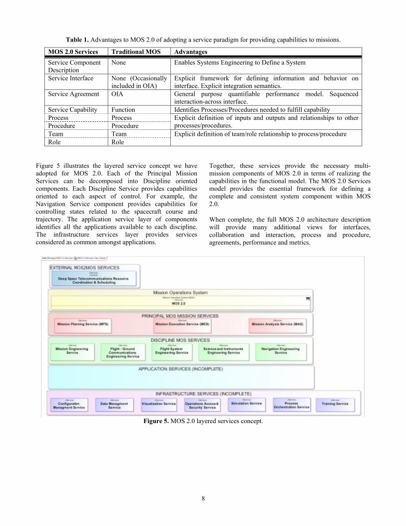
Table 1. Advantages to MOS 2.0 of adopting a service paradigm for providing capabilities to missions.
MOS 2.0 Services Traditional MOS Advantages
Service Component Description
None Enables Systems Engineering to Define a System
Service Interface None (Occasionally included in OIA)
Explicit framework for defining information and behavior on interface. Explicit integration semantics.
Service Agreement OIA General purpose quantifiable performance model. Sequenced interaction-across interface.
Service Capability Function Identifies Processes/Procedures needed to fulfill capability Process Process Explicit definition of inputs and outputs and relationships to other
processes/procedures. Procedure Procedure Team Team Explicit definition of team/role relationship to process/procedure Role Role
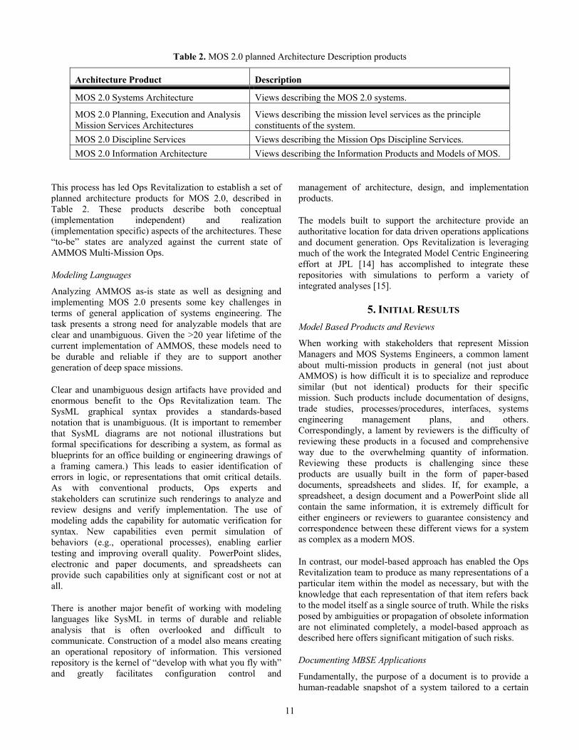
Figure 5 illustrates the layered service concept we have adopted for MOS 2.0. Each of the Principal Mission Services can be decomposed into Discipline oriented components. Each Discipline Service provides capabilities oriented to each aspect of control. For example, the Navigation Service component provides capabilities for controlling states related to the spacecraft course and trajectory. The application service layer of components identifies all the applications available to each discipline. The infrastructure services layer provides services considered as common amongst applications.
Together, these services provide the necessary multi-mission components of MOS 2.0 in terms of realizing the capabilities in the functional model. The MOS 2.0 Services model provides the essential framework for defining a complete and consistent system component within MOS 2.0.
When complete, the full MOS 2.0 architecture description will provide many additional views for interfaces, collaboration and interaction, process and procedure, agreements, performance and metrics.
Figure 5. MOS 2.0 layered services concept.

9
MOS 2.0 Information Architecture
The “as-is” characterization of AMMOS information identified the need for a single information model that unifies existing AMMOS concepts and adds formal concepts for MOS information that are absent or informally defined. The MOS 2.0 information architecture provides this by focusing on the fundamental information concepts for controlling and operating deep space missions.
Ops Revitalization built a conceptual information model based on families of information to break free of the file-focused architecture and to highlight the fundamental information content of an MOS. The information families derive from the various documents, application files, and models used in today’s AMMOS. To organize these abstract categories of information we use SysML specialization relations and generalization sets. The generalization sets constrain the ways in which we may use categories of information to classify items via multiple inheritance. They also give us an economical way to express our ideas and manage complexity.
Figure 6 provides an example of some of the classifications of information in mission operations used in the conceptual architecture. The Mission Operations category identifies the types of information that represent the state of those systems that the MOS must control. The important accomplishment here is the MOS 2.0 is no longer forced to focus on file exchanges with opaque content. The content itself is now the first-class citizen of the system.
Given that the categories are complete (a complete set is considerably more extensive than can be shown in Fig. 6), this approach constrains categorization such that the information families are focused on content relevant to the function being performed.
Linking this information (derived from existing AMMOS files) to the functional models in the MOS 2.0 Conceptual Architecture confirms that the MOS is a control system. An MOS uses a temporal understanding of state to understand and make decisions about the flight system. These information concepts fit best with temporal behavior models and timeline models.
This result provides a concrete direction for constructing the MOS 2.0 Information Ontology. The MOS 2.0 Information Ontology synthesizes concepts from AMMOS as well as Mission Data Systems/State Analysis [8,9] and the ASPEN Modeling Language [10,11] to introduce information concepts that facilitate the achievement of mission and science goals and management of mission resources. These concepts center on temporally constrained behavior models and timeline models, which consist of the states and events of interest along with the temporal and value constraints placed upon those states and events. While the basis for these concepts is relatively straightforward, the details of its application and the interrelationships between state, event, and constraints (both value and temporal) are complex. A thorough discussion of the technical details is outside the scope of this paper.
Considering the fact that the MOS must command and control the mission assets, these information models become the medium of exchange between the services and associated processes that permit the effective operation of the Mission. Since we wish to use our goals (e.g., the successful collection of scientific observations) as the means by which the system is directed and controlled, the information must account for dynamics and must be structured to easily support comparison of predicted to measured or observed outcomes. With such feedback, we are able to meet our goals of ensuring and improving upon performance.
Figure 6. Illustration of a portion of the MOS 2.0 classifications for information. This representation focuses on information content as opposed to file types or filenames, reasserting the primacy of the information itself over a specific representation.

10
By adopting timelines as an information framework, we capture the necessary behaviors, states, and constraints needed for the MOS to produce products to command and control the mission assets. This basic framework provides specialization options that can span the transition from the current file-based AMMOS information products to sophisticated information products that fully support a fully reconciled MOS that embraces state analysis to monitor and control the Mission.
For example, consider placing the functions in Figure 4 on a timeline for the mission. The planning functions produce a collection of timelines that capture all of the intended states for the next uplink. The execution function implements these timelines on the spacecraft and ground communications and reports the observed timelines to the analysis functions. The analysis functions reconcile the predicted timelines with the observed timelines and update the known states of the spacecraft for the next planning cycle.
Such multi-mission scenarios can be specialized to accommodate anything from a rover’s tactical timeline to a planetary orbiter’s more strategic planning cycle. Since these functions correspond to services, a major portion of the capabilities each service provides focus on various operations performed on a timeline to predict, simulate, plan, execute and analyze behavioral effects on state.
Model Based Systems Engineering
The systems engineering work required to architect MOS 2.0 necessitates an enormous amount of information capture and analysis. Ops Revitalization is applying the discipline of Model Based Systems Engineering (MBSE) [13,14] as the means to efficiently and effectively perform all of the systems engineering work for the task.
Modeling and Architecture Driven by Stakeholder Focused Process
Meaningful application of these principles through architecture requires directly collaborative, accountable
engagement with stakeholders as a fundamental part of performing systems engineering.
Involving stakeholders in the process of developing the architecture is key to drawing out the tensions between competing objectives and constraints. Mission Operations is conflicted between pursuing innovative technologies and minimizing risk, both during Mission development and during operations. Technology can be used to improve Mission Operations, but the benefits and impacts need to be clearly understood to maintain multiple working MOS’s at minimal risk, while evolving and updating the overall AMMOS across multiple Project lifecycles.
In the earliest phase of the Ops Revitalization task, stakeholder concerns were captured as operations scenarios. These were structured text descriptions of a system level objective written as a trajectory of steps or activities describing inputs to an operational model, supported by (informal) diagrams. These scenarios facilitated the creation of the concept models for MOS 2.0 [1,2]. They were created in a collaborative, interactive engagement between Ops Revitalization engineers and domain experts who held a stake in the quality of the scenarios and in MOS 2.0.
With the adoption of the ISO-42010 [5] standard for architecture, this stakeholder engagement has now been elaborated into an architectural process. Figure 7 depicts the basic steps of preparing the architectural viewpoint in terms of 1) identifying concerns and potential stakeholders, 2) collaborating with those stakeholders to define the viewpoint, 3) implementing the viewpoint with a view and 4) reviewing the package with the stakeholders.
The benefits of using this formal method include close, regular communication between the stakeholders and the systems engineering team. The systems engineering team receives valuable incremental feedback with stakeholders and stakeholders are continually investing in the MOS 2.0 design. Together they collaborate in balancing competing concerns using the architecture principles and the experience of the team and stakeholders.
Figure 7. SysML activity diagram of the Ops Revitalization stakeholder engagement process.
11
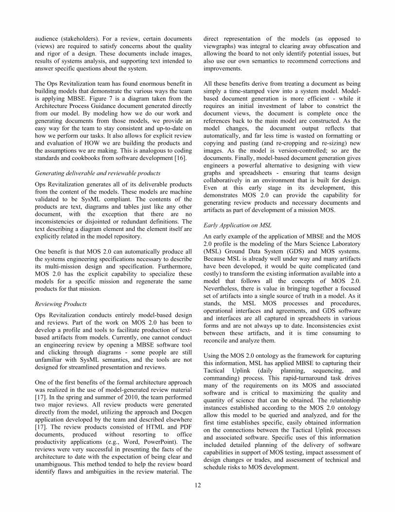
Table 2. MOS 2.0 planned Architecture Description products
Architecture Product Description
MOS 2.0 Systems Architecture Views describing the MOS 2.0 systems.
MOS 2.0 Planning, Execution and Analysis Mission Services Architectures
Views describing the mission level services as the principle constituents of the system.
MOS 2.0 Discipline Services Views describing the Mission Ops Discipline Services.
MOS 2.0 Information Architecture Views describing the Information Products and Models of MOS.
This process has led Ops Revitalization to establish a set of planned architecture products for MOS 2.0, described in Table 2. These products describe both conceptual (implementation independent) and realization (implementation specific) aspects of the architectures. These “to-be” states are analyzed against the current state of AMMOS Multi-Mission Ops.
Modeling Languages
Analyzing AMMOS as-is state as well as designing and implementing MOS 2.0 presents some key challenges in terms of general application of systems engineering. The task presents a strong need for analyzable models that are clear and unambiguous. Given the >20 year lifetime of the current implementation of AMMOS, these models need to be durable and reliable if they are to support another generation of deep space missions.
Clear and unambiguous design artifacts have provided and enormous benefit to the Ops Revitalization team. The SysML graphical syntax provides a standards-based notation that is unambiguous. (It is important to remember that SysML diagrams are not notional illustrations but formal specifications for describing a system, as formal as blueprints for an office building or engineering drawings of a framing camera.) This leads to easier identification of errors in logic, or representations that omit critical details. As with conventional products, Ops experts and stakeholders can scrutinize such renderings to analyze and review designs and verify implementation. The use of modeling adds the capability for automatic verification for syntax. New capabilities even permit simulation of behaviors (e.g., operational processes), enabling earlier testing and improving overall quality. PowerPoint slides, electronic and paper documents, and spreadsheets can provide such capabilities only at significant cost or not at all.
There is another major benefit of working with modeling languages like SysML in terms of durable and reliable analysis that is often overlooked and difficult to communicate. Construction of a model also means creating an operational repository of information. This versioned repository is the kernel of “develop with what you fly with” and greatly facilitates configuration control and
management of architecture, design, and implementation products.
The models built to support the architecture provide an authoritative location for data driven operations applications and document generation. Ops Revitalization is leveraging much of the work the Integrated Model Centric Engineering effort at JPL [14] has accomplished to integrate these repositories with simulations to perform a variety of integrated analyses [15].
5. INITIAL RESULTS
Model Based Products and Reviews
When working with stakeholders that represent Mission Managers and MOS Systems Engineers, a common lament about multi-mission products in general (not just about AMMOS) is how difficult it is to specialize and reproduce similar (but not identical) products for their specific mission. Such products include documentation of designs, trade studies, processes/procedures, interfaces, systems engineering management plans, and others. Correspondingly, a lament by reviewers is the difficulty of reviewing these products in a focused and comprehensive way due to the overwhelming quantity of information. Reviewing these products is challenging since these products are usually built in the form of paper-based documents, spreadsheets and slides. If, for example, a spreadsheet, a design document and a PowerPoint slide all contain the same information, it is extremely difficult for either engineers or reviewers to guarantee consistency and correspondence between these different views for a system as complex as a modern MOS.
In contrast, our model-based approach has enabled the Ops Revitalization team to produce as many representations of a particular item within the model as necessary, but with the knowledge that each representation of that item refers back to the model itself as a single source of truth. While the risks posed by ambiguities or propagation of obsolete information are not eliminated completely, a model-based approach as described here offers significant mitigation of such risks.
Documenting MBSE Applications
Fundamentally, the purpose of a document is to provide a human-readable snapshot of a system tailored to a certain
12
audience (stakeholders). For a review, certain documents (views) are required to satisfy concerns about the quality and rigor of a design. These documents include images, results of systems analysis, and supporting text intended to answer specific questions about the system.
The Ops Revitalization team has found enormous benefit in building models that demonstrate the various ways the team is applying MBSE. Figure 7 is a diagram taken from the Architecture Process Guidance document generated directly from our model. By modeling how we do our work and generating documents from those models, we provide an easy way for the team to stay consistent and up-to-date on how we perform our tasks. It also allows for explicit review and evaluation of HOW we are building the products and the assumptions we are making. This is analogous to coding standards and cookbooks from software development [16].
Generating deliverable and reviewable products
Ops Revitalization generates all of its deliverable products from the content of the models. These models are machine validated to be SysML compliant. The contents of the products are text, diagrams and tables just like any other document, with the exception that there are no inconsistencies or disjointed or redundant definitions. The text describing a diagram element and the element itself are explicitly related in the model repository.
One benefit is that MOS 2.0 can automatically produce all the systems engineering specifications necessary to describe its multi-mission design and specification. Furthermore, MOS 2.0 has the explicit capability to specialize these models for a specific mission and regenerate the same products for that mission.
Reviewing Products
Ops Revitalization conducts entirely model-based design and reviews. Part of the work on MOS 2.0 has been to develop a profile and tools to facilitate production of text-based artifacts from models. Currently, one cannot conduct an engineering review by opening a MBSE software tool and clicking through diagrams - some people are still unfamiliar with SysML semantics, and the tools are not designed for streamlined presentation and reviews.
One of the first benefits of the formal architecture approach was realized in the use of model-generated review material [17]. In the spring and summer of 2010, the team performed two major reviews. All review products were generated directly from the model, utilizing the approach and Docgen application developed by the team and described elsewhere [17]. The review products consisted of HTML and PDF documents, produced without resorting to office productivity applications (e.g., Word, PowerPoint). The reviews were very successful in presenting the facts of the architecture to date with the expectation of being clear and unambiguous. This method tended to help the review board identify flaws and ambiguities in the review material. The
direct representation of the models (as opposed to viewgraphs) was integral to clearing away obfuscation and allowing the board to not only identify potential issues, but also use our own semantics to recommend corrections and improvements.
All these benefits derive from treating a document as being simply a time-stamped view into a system model. Model-based document generation is more efficient - while it requires an initial investment of labor to constrict the document views, the document is complete once the references back to the main model are constructed. As the model changes, the document output reflects that automatically, and far less time is wasted on formatting or copying and pasting (and re-cropping and re-sizing) new images. As the model is version-controlled; so are the documents. Finally, model-based document generation gives engineers a powerful alternative to designing with view graphs and spreadsheets - ensuring that teams design collaboratively in an environment that is built for design. Even at this early stage in its development, this demonstrates MOS 2.0 can provide the capability for generating review products and necessary documents and artifacts as part of development of a mission MOS.
Early Application on MSL
An early example of the application of MBSE and the MOS 2.0 profile is the modeling of the Mars Science Laboratory (MSL) Ground Data System (GDS) and MOS systems. Because MSL is already well under way and many artifacts have been developed, it would be quite complicated (and costly) to transform the existing information available into a model that follows all the concepts of MOS 2.0. Nevertheless, there is value in bringing together a focused set of artifacts into a single source of truth in a model. As it stands, the MSL MOS processes and procedures, operational interfaces and agreements, and GDS software and interfaces are all captured in spreadsheets in various forms and are not always up to date. Inconsistencies exist between these artifacts, and it is time consuming to reconcile and analyze them.
Using the MOS 2.0 ontology as the framework for capturing this information, MSL has applied MBSE to capturing their Tactical Uplink (daily planning, sequencing, and commanding) process. This rapid-turnaround task drives many of the requirements on its MOS and associated software and is critical to maximizing the quality and quantity of science that can be obtained. The relationship instances established according to the MOS 2.0 ontology allow this model to be queried and analyzed, and for the first time establishes specific, easily obtained information on the connections between the Tactical Uplink processes and associated software. Specific uses of this information included detailed planning of the delivery of software capabilities in support of MOS testing, impact assessment of design changes or trades, and assessment of technical and schedule risks to MOS development.
13
6. ANTICIPATED RESULTS AND FUTURE PLANS
Through guidance by MOS Principles and application of industry standards, the Ops Revitalization team has
Analyzed As-Is AMMOS in the light of well-articulated architectural principles
Determined key directions for MOS 2.0
Established a formal model based conceptual systems architecture
Established an information architecture
The next steps revolve around how to begin to transition to this “to-be” state from the current state and begin to implement MOS 2.0 as part of the ongoing development of AMMOS. Given the paradigm shifts in MOS 2.0, this is not as simple as “throwing it over the wall” to be implemented. A comprehensive transition plan is required. The transition will first revolve around implementing the Discipline services as shown in Figure 5. The high-level plan is as follows:
FY 11
Completing the Systems Architecture and Information Architecture Models/Descriptions
Implementing Flight-Ground Communications Service
FY 12-13
Implementing additional discipline services
Implementing the Multi-mission MOS 2.0 System
The implementation of the Flight-Ground Communications Service will be a fully operational multi-mission service built against the existing AMMOS software. This is very important transitional step as it will be the first Mission-usable application of the MOS 2.0 design work. Multi-mission Ground Systems and Services (MGSS) will carry out the development and maintenance of subsequent versions of all the services Ops Revitalization builds as they incorporate them into the services catalog. Each of these multi-mission services is expected to identify:
How well the current software meets the different needs of mission operations
How complete a set of capabilities the service is able to provide
The degree to which the service complies with MOS 2.0 Systems and Information Architecture.
The future needs of the service in order to comply with MOS 2.0 and/or provide capabilities to existing and future customers.
As we complete the implementation of the services and ultimately the multi-mission MOS 2.0, we expect to have taken the first steps toward the next revolution in mission operations – a configuration driven information system capable operating and simulating any mission in the solar system from concept (cradle) to end-of-mission (grave).
ACKNOWLEDGEMENTS.
This research was conducted at the Jet Propulsion Laboratory, California Institute of Technology, under a contract with the National Aeronautics and Space Administration.
REFERENCES
[1] Duane L. Bindschadler, Carole A. Boyles, Carlos Carrion, and Christopher L. Delp, MOS 2.0: The Next Generation in Mission Operations Systems, SpaceOps 2010 Conference, Huntsville, AL, USA, April, 2010.
[2] Carlos Carrion, Christopher L. Delp, Jeannette Illsley, and Otfrid Liepack, “Use of Operational Scenarios in Architecting MOS 2.0”, SpaceOps 2010 Conference, Huntsville, AL, USA, April, 2010.
[3] Object Management Group, OMG Systems Modeling Language (OMG SysMLTM), Version 1.1, November 2008.
[4] IEEE Std 1471-2000, IEEE Recommended Practice for Architectural Description of Software-Intensive Systems.2004.
[5] ISO, ISO/IEC 42010 Systems and Software Engineering — Architectural Description, July 2007.
[6] Marc A. Sarrel, Carlos Carrion, Joseph C. Hunt, Jr., “Managing the On-Board Data Storage, Acknowledgement and Retransmission System for Spitzer,” SpaceOps 2006 Conference, Reston, VA, USA, 2006
[7] Marc A. Sarrel and Michael Turmon, “Improved Estimates of Spitzer Space Telescope Data Volumes with Error Bars,” SpaceOps 2008 Conference, Heidelberg, Germany, 2008.
[8] D. Dvorak, M. Indictor, M. Ingham, R. Rasmussen, and M. Stringfellow, “A Unifying Framework for Systems Modeling, Control Systems Design, and System Operation,” IEEE System, Man, and Cybernetics Conference, Kona, HI, USA, October 2005.
14
[9] M. Bennett, D. Dvorak, J. Hutcherson, M. Ingham, R. Rasmussen, and D. Wagner, “An Architectural Pattern for Goal-Based Control,” IEEE Aerospace Conference, Big Sky, MT, USA, March 2008.
[10] S. Chien, G. Rabideau, R. Knight, R. Sherwood, B. Engelhardt, D. Mutz, T. Estlin, B. Smith, F. Fisher, T. Barrett, G. Stebbins, and D. Tran, “ASPEN - Automating Space Mission Operations using Automated Planning and Scheduling,” International Conference on Space Operations (SpaceOps 2000). Toulouse, France. June 2000
[11] S. Chien, D. Tran, G. Rabideau, S. Schaffer, D. Mandl, and S. Frye, “Timeline-based Space Operations Scheduling with External Constraints,” International Conference on Automated Planning and Scheduling (ICAPS 2010). Toronto, Canada. May 2010
[12] OASIS Reference Model for Service Oriented Architecture 1.0, (2005-2006), Retrieved from OASIS: http://www.oasis-open.org
[13] A. Wayne Wymore, Model-Based Systems Engineering, New York: CRC Press, 1993
[14] Todd J. Bayer, Lauren A. Cooney, Christopher L. Delp, Chelsea A. Dutenhoffer, Roli D. Gostelow, Michel D. Ingham, J. Steven Jenkins, Brian S. Smith, “An operations concept for integrated model-centric engineering at JPL,” IEEE Aerospace Conference Proceedings (1095-323X), 2010.
[15] Bjorn Cole, Christopher L. Delp, and Kenneth Donahue, "Piloting Model Based Engineering Techniques for Spacecraft Concepts," INCOSE International Symposium 2010, Chicago, IL, USA, June, 2010
[16] Robert Karban, Tim Weilkiens, Rudolf Hauber Rainer Diekmann, Michele Zamparelli, OMG Telescope Modeling Challenge, http://www.omgwiki.org/MBSE/doku.php?id=mbse:telescope.
[17] Maddalena Jackson, Christopher L. Delp, Duane L. Bindschadler, Marc A. Sarrel, Ryan Wollaeger, and Doris Lam, “Dynamic Gate Product and Artifact Generation from System Models,” IEEE Aerospace 2011 Conference, Big Sky MT, USA, March 2011.
BIOGRAPHY
Christopher L. Delp is the Systems Architect for the Ops Revitalization task in MGSS. He is also a member of the Flight Software Systems Engineering and Architectures Group at the Jet Propulsion Laboratory. His interests include software
and systems architecture, applications of model-based systems engineering, and real-time embedded software engineering. He earned his M.S. and B.S. degrees from the University of Arizona in Systems Engineering.
Duane Bindschadler is the Assistant. Program Manager for
Operations in Multimission Ground Systems and Services (MGSS) at JPL and Project Manager of the AMMOS Operations Revitalization Initiative. Previously, he led Ground System development efforts for the Space Interferometry Mission, and led Flight Operations and Science Operations during Galileo's extended tour of the Jovian System. Before coming to JPL, he held research and adjunct faculty positions in Earth and Space Sciences at UCLA. Dr. Bindschadler has a Ph.D. and M.Sc. in Geology from Brown University and a B.S. in Physics from Washington University, St. Louis.
Ryan Wollaeger is a research assistant in the Nuclear Engineering and Engineering Physics graduate program at the University of Wisconsin, Madison. He spent the summer of 2010 supporting the AMMOS Ops Revitalization DocGen effort under the supervision of Christopher Delp and Maddalena Jackson.
Carlos Carrion has been at JPL since 1988 working in mission operations, technology development, system engineering, and software engineering/development. He has contributed projects and programs including Voyager, Galileo, Magellan, Mars Observer, Space Flight
Operations Center, Cassini, Starlight, Space Technology 8, Spitzer, Center for Space Mission Architecture and Design, Space Project Mission Operations Control Architecture, Dawn, and MGSS. His Project lifecycle experience includes working projects from Step1 proposals all the way through Operations. He has a B.S. in Physics and a B.A. in Music.

15
Michelle McCullar is currently a Systems Architect for the Ops Revitalization task in the Multimission Ground Systems and Services Program Office and is active in the JPL modeling community. She has worked on various JPL Programs and Flight Projects since January 1988, including TOPEX, Magellan, Mars Observer,
AIRS, Cassini, SIM, MDS, MSL, and Kepler. She has worked and led various efforts in the areas of Ground Data System and Mission Operations System design and development, Flight Subsystem software development and hardware and software integration and test, Spacecraft Integration, Test and Launch Operations, System Verification and Validation, Spacecraft Operations, Proposal Development, and Model Based System Engineering. Michelle has a M.S. in Engineering Computer Science and a B.B.A. in Business Analysis and Computer Information Systems from Texas A&M University.
Maddalena Jackson is a Software Systems Engineer at the JPL since January 2009. She is the main architect and developer of the Document Generator. She graduated from Harvey Mudd College in Claremont, CA in 2008 with a Bachelor of Science in General Engineering. She has previously worked in fields ranging from renewable energy
analysis to lizard ecology, and completed an AAAS Mass Media Fellowship as a science writer at the Sacramento Bee before starting at JPL. At JPL, she is currently working as a Ground Data Systems Engineer and an Integration, Test, and Deployment engineer on the Juno mission, and is active in JPL’s modeling community
Marc Sarrel currently works on the Operations Revitalization task in MGSS, the Multimission Ground Systems and Services Program Office. He has worked on various JPL flight project over the past twenty years, including Mars Observer, Magellan, Cassini and the Spitzer Space Telescope. He has worked in the areas of software
development, Ground Data Systems and Mission Operations Systems, including as the Mission Operations Systems Engineer for Spitzer. Marc has worked on a number of Model Based Systems Engineering tasks, in addition to Operations Revitalization, including on the Ares I project and the Constellation Program Software and Avionics Office. He has also participated in the INCOSE Model-Based Systems Engineering grand challenge on the team from the Space Systems Working Group, where he also serves as communications coordinator. Marc has a B.S. in Computer Science from Washington University in St. Louis, and an M.S. in Computer and Information Science from The Ohio State University.
Louise Anderson is an early career hire in Software Systems Engineering at JPL and is a member of the Ops Revitalization team in MGSS. She graduated in May 2010 from the University of Colorado-Boulder with a degree in Aerospace Engineering. Previously she worked at the Laboratory
for Atmospheric Space Physics in Boulder Colorado working as a Command Controller on the Mission Operations Team. She has worked on the mission ops team for Kepler, Sorce, AIM, Quikscat, and Icesat. Louise is also currently a member of the Modeling Early Adopters group.
Doris Lam is a Software Systems Engineer and part of the Ground Software Architecture and System Engineering Group at Jet Propulsion Laboratory since August 2008. She obtained her B.S. in Computer Science from UCLA before joining JPL. She has previously worked in the POQ Information Systems department at Amgen, and as a research scholar at UCLA’s Center for Embedded Networked Sensing, where she participated in the development of a software system for capturing, analyzing, and displaying location (GPS) information from cell phones. She is active in the modeling community at JPL and is currently applying a model-based approach to capture and analyze Mars Science Lab (MSL) operations processes.