moreland apartment design codemoreland.vic.gov.au/globalassets/areas/amendments/... · design...
TRANSCRIPT

MORELAND APARTMENT
DESIGN CODE
SEPTEMBER 2015

MORELAND APARTMENT DESIGN CODE2015
Disclaimer:
Information and events contained in this publication are current at the time of printing. Subsequent changes to events/information
may occur. Although the publication may be of assistance to you, Moreland City Council does not guarantee that it is without fl aw
of any kind or is wholly appropriate for your particular purposes. It and its employees do not accept any responsibility, and indeed
expressly disclaim any liability, for any loss or damage, whether direct or consequential, suffered by any person as the result of or
arising from reliance on any information contained in the publication.
© All applicable copyrights reserved for Moreland City Council. Except for any uses permitted under the Copyright Act 1968 (Cth),
no part of this publication may be reproduced in any manner or in any medium (whether electronic or otherwise) without the
express permission of Moreland City Council.
Moreland City Council 90 Bell Street ,Coburg VIC 3058
3
Part A - Introduction
A.1 Purpose 5
A.2 Application of MADC 5
A.3 Operation 5
Part B - Pre-application and Application
Requirements
B.1 Pre-application process 9
B.2 Application requirements 10
B.3 Urban context report, local context report 10
and design response
B.3.1 Urban context report 10
B.3.2 Local context report 11
B.3.3 Design response 11
B.3.3.1 Preliminary design response 11
B.3.3.2 Final design response 12
Part C - Building Types
C.1 Building Types 15 C.1.1 Narrow Lot Building 17 C.1.2 Block Building 18 C.1.3 Slab Building 19 C.1.4 Tower Building 21 C.1.5 Courtyard Building 22 C.1.6 Hybrid Building 23
Table of Contents
Part D - Assessment Provisions
D.1 Passive Design Elements 27
D.1.1 Building orientation 27
D.1.2 Building separation 28 D.1.3 Daylight access 33
D.1.4 Natural ventilation 36
D.1.5 Thermal comfort 38
D.2 Internal Amenity and Facilities 40
D.2.1 Dwelling diversity 40
D.2.2 Dwelling size and layout 41
D.2.3 Pedestrian entry and circulation 44
D.2.4 Acoustic performance 48
D.2.5 Private open space 50
D.2.6 Privacy 52
D.2.7 Open space and landscape design 56
D.2.8 Communal facilities 58
D.2.9 Site services 60
C.2.9.1 Bicycle and car parking 60
C.2.9.2 Private storage space 64
C.2.9.3 Waste management 65
Appendix
MADC Checklist 69
Image Credits 80

4
MORELAND APARTMENT DESIGN CODE

5
This section provides a summary of the Code’s purpose, the type of developments that it applies to as well as its relationship to other planning scheme controls and the operation of the Code’s requirements.
A.1 Purpose
The purpose of the Moreland Apartment Design Code (MADC) is to improve the quality of higher density mixed use and residential development in the municipality. Council is seeking a higher standard of design that maximises opportunities for passive design, provides good amenity and facilities for residents and addresses the reasonable development opportunities of adjoining sites. Overall Council expects apartment development to provide for the health and wellbeing of its residents.
A.2 Application of MADC
The MADC’s objectives, standards and decision guidelines are also included in Clause 22.07 of the Moreland Planning Scheme. The MADC is a reference document in the Moreland Planning Scheme. Accordingly, the MADC must be used when assessing relevant planning permit applications.
The MADC will apply to mixed use and residential development of fi ve or more storeys.
The MADC may be used for guidance for residential development under fi ve storeys to encourage a higher standard of design, particularly for building types that provide for apartment style development.
Applications for development requiring an assessment under the MADC will be considered in conjunction with Council’s place-based strategies such as structure plans, built form frameworks or other site-specifi c policies and provisions. These matters address public realm issues as such building height, upper level setbacks, street wall heights and interface to surrounding residential areas.
Should there be any confl ict between a requirement in the MADC and a place-based policy or provision, the place-based policy or provision prevails.
Part A - Introduction
6
MORELAND APARTMENT DESIGN CODE
A.3 Operation
The MADC is structured into the following parts:
Part A – Introduction
This section provides a summary of the Code’s purpose, the type of developments that it applies to as well as its relationship to other planning scheme controls and the operation of the Code’s requirements.
Part B – Pre-application process, application requirements, urban context report, local context report and design response
This part provides an overview of the pre-application processes that should be followed when applying for an apartment development of fi ve or more storeys and explains the information that must be provided in the urban context report, local context report and design response. The information to be provided is additional to the requirements of Clause 52.35 of the Victoria Planning Provisions (VPPs) (Urban Context Report and Design Response for Development of Four or More Storeys)
Part C – Building TypesThis part contains the different building types that maybe suitable for a particular type of site and context. The purpose of defi ning building types is to identify the built form considered ideal for various sites common to Moreland.
Part D – Assessment ProvisionsThis part contains the objectives, standards and decision guidelines on mixed use residential development and residential development of fi ve or more storeys.
Objectives – describe the outcome to be achieved and must be met.
Standards – outline specifi c requirements that are considered necessary to achieve the objectives. Standards should normally be met. However, if the responsible authority is satisfi ed that a proposal for an alternative design solution meets the objective, an alternative may be considered.
Decision Guidelines – identify the factors the responsible authority will consider when assessing an application for planning permit. These factors include any relevant structure plan, policy or planning provision applying to the area, the opportunities and constraints of the site, the design response and the design guidelines.
Design Guidelines – provide advice on good design solutions that are considered suitable to meet the objectives and standards in common circumstances. Alternative design solutions can also be considered if it can be demonstrated that the objectives and standards are met.

PART B
PRE - APPLICATION AND
APPLICATION REQUIREMENTS

8
MORELAND APARTMENT DESIGN CODE

9
PART B PRE-APPLICATION AND APPLICATION REQUIREMENTS
Part B - Pre-application and
Application Requirements
This section contains information on the pre-application process, application requirements, urban context report, local context report and design response requirements.
indicative design response having regard to the relevant planning objectives applying to the area, the nature of the building type and building envelope that may be appropriate for the site context, the nature of building envelopes of adjoining sites that address reasonable development opportunities of those sites and the information that should be submitted with the application.
Second Pre-application meeting
At the second pre-application meeting a fi nal draft of the urban context report and design response that responds to the issues raised by Council offi cers must be provided. Council offi cers will provide further written comments on any outstanding issues to be resolved prior to the lodgement of a planning application.
B.1 Pre-application process
Buildings exceeding fi ve or more storeys that contain a mix of commercial and residential uses often require a complex set of issues to be resolved to achieve a high quality outcome. The vast majority of such developments will occur in Moreland’s activity centres, where there is already a complicated mixture of existing uses and built form. Against this background, Council considers that it may be appropriate to hold at least two pre-application meetings with Council offi cers.
Details of how to organise a pre-application meeting and what can be expected from a pre-application meeting are found on Council’s website www.moreland.vic.gov.au/pre-app. A pre-application request can be downloaded from this webpage.
First pre-application meeting
It is appropriate to hold a pre-application meeting to consider a draft site urban context report and indicative design response using the Code’s Building typologies as a guide to identify the relevant planning and urban design issues that may affect the design parameters of the proposal and the reasonable development opportunities of adjoining sites. Council offi cers will provide feedback on the draft urban context report and
B.1 MADC Application Flow Chart
● Prepare urban context report and preliminary design response by applying Code building types
● Consider equitable development on adjoining sites
STEP 1
● Request fi rst pre-application meeting
STEP 2
● Address issues raised by Council offi cers
● Finalise urban context report and preliminary design responseSTEP 3
● Request second pre-application meeting
STEP 4
● Submit fi nal draft urban context report and design response including indicative building envelopes of adjoining sites (where appropriate)STEP 5
● Lodge application ensuring all information is provided
STEP 6

10
MORELAND APARTMENT DESIGN CODE
B.2 Application requirements
Council has prepared The planning process - A guide for applicants which is available from Council’s website www.moreland.vic.gov.au/urban-plan-guide to assist applicants apply for a planning permit. This Guide explains the information that must be submitted with an application.
In addition to the information that should be provided under the Guide, an application requiring an assessment under the MADC should include the following plans:
• Streetscape elevations articulating the existing streetscape (including any approved developments that will change the streetscape) and how the proposal sits within the elevation
• A three-dimensional perspective of the proposed development within the streetscape in the context of adjacent development
• Section diagrams of the proposed building(s)• Potential building typologies of adjoining developable sites to ensure the reasonable development opportunities
of those sites• Shadow diagrams including sectional shadow diagrams identifying shadow impacts at different levels on
adjoining properties and the public realm at hourly intervals between 9am and 3pm• Concept landscape plan• Demolition plan in applications involving the demolition of a heritage building
Other supporting reports should include (but is not limited to) the following:• A written report providing a response to each element in this Code• Completion of the MADC Checklist (See Appendix)• A Sustainability Management Plan (SMP) • An Accessibility Report (where appropriate, accessibility features must be clearly shown in all associated plans
and architectural drawings)• An Acoustic Report (generally for sites adjoining main roads, rail lines, industrial areas and live music venues)
demonstrating compliance with section D.2.4 of this Code• A preliminary site assessment prepared by a suitably qualifi ed environmental professional identifying potential
contamination risk • A Waste Management and Disposal Plan • A Traffi c report and car parking demand assessment in accordance with Clause 52.06-6 of the VPPs
B.3 Urban context report, local context report and design response
An urban context and design response must be provided in accordance with Clause 52.35 of the Victoria Planning Provisions (Urban Context Report and Design Response for Residential Development of Four or More Storeys).
B.3.1 Urban Context Report
In addition to the requirements of Clause 52.35-02, the urban context report should include plans showing: • Existing and emerging building types in the area• Location of proposed building(s) relative to the footprints, heights, open space, balconies and habitable rooms

11
PART B PRE-APPLICATION AND APPLICATION REQUIREMENTS
windows of surrounding buildings • Indicative building envelopes of developable adjoining sites • Prevailing street setbacks and street wall/podium heights• Assessment of streetscape which analyses building form, scale and rhythm• Heritage buildings and heritage streetscapes• Existing shadow impacts on the subject land and surrounding properties
B.3.2 Local Context Report
Local context provides the larger picture of the area, approximately 800 to 1000 metres radius from the site.
A local context analysis should include:• The location of local shops, public transport services and public open spaces within fi ve minutes walking
distance (400 metres) and 10 minutes walk (800 metres) from the site• Any signifi cant environmental features such as vegetation, topography and signifi cant views• Any major facilities and institutions such as schools, hospitals etc.
B.3.3 Design response
The design response is to be undertaken in two stages: the preliminary design response and the fi nal design response. The purpose of the preliminary design response is to assist in the preparation of the pre-application meeting with Council offi cers so that formal written comments can be provided to applicants. The purpose of the fi nal design response is to provide an opportunity to make any changes to the proposal as a result of the Council offi cer’s written response.
B.3.3.1 Preliminary design response
The design principles should be established to reiterate fi ndings from the urban context report and respond to the analysis of opportunities and constraints. The preliminary design response must be presented prior to the fi rst pre-application meeting.
The preliminary design response must, as a minimum, include the following:
Design Principles and Site Response• Proposed building type and indicative building envelope, including building depth. Building types suitable for
Moreland are identifi ed in Part C and should be based on the relevant planning objectives and strategies for the area, site size, orientation, location within a block and surrounding development patterns.
• Indicative building envelopes of developable adjoining properties to demonstrate the reasonable development opportunities of these properties.
• Building envelope showing proposed building height, building depth and building separation in the context of surrounding buildings (and take account of any approved development) as well as ground level and upper level setbacks and streetwall/podium heights.
• Identifi cation of any signifi cant vegetation and mature trees on the site or surrounding the site, if applicable.• Proposed uses in context of the planning provisions affecting the site and surrounding building uses.

12
MORELAND APARTMENT DESIGN CODE
Building EnvelopeA graphic demonstration showing the proposed three-dimensional built form massing should be presented to communicate the design principles. This can be in the form of a hand drawn sketch or a block 3D perspective and should demonstrate how the proposed design:
• Responds to solar orientation to maximise the energy effi ciency of the building• Provides appropriate building type suited to the site’s size, shape and orientation• Provides appropriate building depth that will allow for passive design elements to be achieved• Achieves appropriate building separation• Relates to and improves the street character• Responds to existing surrounding buildings in terms of scale and setbacks• Responds to any relevant planning schemes provision and any relevant policy directions, including preferred
future built form outcomes for the site if applicable
OrientationOrientation is critical to demonstrate how the proposed design maximises solar access, achieves natural ventilation and addresses the public realm.
StreetscapeStreetscape demonstrates how the proposed design relates to the street in term of scale, proportion and rhythm, ground fl oor articulation and street activation through design. Streetscape should be demonstrated in the form of street elevation.
Internal LayoutInternal layout identifying the main outlook, access to daylight and natural ventilation is important to enhance internal amenity. The internal layout should also show the location of lift core, circulation corridors, commercial occupancies and dwellings should be illustrated in the form of sketch design.
OvershadowingThe proposed built form should maximise solar access to communal open space, private open space and dwellings. Shadow diagrams should be developed based on the proposed building envelope to demonstrate the overshadowing impacts of the proposed design on existing properties and the public realm. Shadow diagrams should be taken at 9am, 12pm and 3pm on the Equinox or Solstice (refer to relevant place-based strategy).
B.3.3.2 Final design response
The fi nal design response is the fi nal detailed documentation of the proposed design. It should respond to feedback and revision of the preliminary design response.
The fi nal design response generally includes:• Any revised preliminary design response diagrams• Final architectural drawings for planning application including fl oor plans, elevations and sections• Detailed shadow diagrams of the fi nal design• Other additional requirements indicated during the pre-application meeting process

PART C
BUILDING TYPE


PART C BUILDING TYPE
15
W<D/5<750m2
W<D250-5000m2
W≈D>750m2
W>D>750m2
All lot types have variations with a corner lot or having more than one street frontage
W (Width)
D (D
epth
)
What is a building type?A variety of design solutions are possible for a particular development site based on site size, orientation, street frontage and site context. A building type is a generic building form that is suitable for a particular type of site and context. It is not a building but a desired 3D envelope which can be modifi ed to allow site-specifi c response and architectural details. The purpose of defi ning building types is to identify the built form considered ideal for various sites common to Moreland.
Possible building types should be considered as part of the Urban Context Report and Design Response process. A preferred building type should be identifi ed and confi rmed with Council offi cers at pre-application stage.
Building types for MorelandThe building types identifi ed for Moreland are derived on the basis of the most common lot types suitable for higher density development in Moreland.
For the purposes of the Code the building types are limited to buildings fi ve storeys or higher. Larger sites may have a combination of more than one building type. This provides for design choice and variation in the building form and fl exibility to the designer. Suitable building types specifi c to Moreland are:
• Narrow Lot Building• Block Building• Slab Building• Tower Building• Courtyard Building• Hybrid Building
The building types illustrated in this document are primarily suited to activity centres and shopping strips where increased density is considered desirable. Variation to some of the building types can be suitable for other areas and this has been illustrated where possible.
C.1 Most common lot types in Moreland
Part C - Building Types

16
MORELAND APARTMENT DESIGN CODE
W<D/5 W<D W≈D W>D
XS<250m2
S250 - 750m2
M750 - 2000m2
L2000 - 5000m2
XL>5000m2
Narrow Lot Building
Block Building
Slab Building
Tower Building
Courtyard Building
Hybrid Building
WidthDepth
Most common lot types in Moreland
A
A
A
D
B
E
D
FF
F F
E
EB
C
EE
E ED DC
C
CC
B
F
WD
A
Building type selection matrixThe building type selection matrix below illustrates the building types ideal for various lot types and lot sizes. The lot types are plotted on the top and the lot sizes are plotted on the left hand side. The blue boxes indicate the most common lot size and type combination found within Moreland, and makes recommendation for the most suitable building type.
The building types suggested for each lot type and size combination is considered the most suitable, however other options might be possible based on the exact size and context of a site.The lot types indicated above show mid-block location but each lot type can have variations (e.g. a corner site, more than one street frontage etc.). In this case the building type will have slight variations based on the individual context.
Table C.1.a : Building Type Selection Matrix

PART C BUILDING TYPE
17
C.1 NARROW LOT BUILDING
Narrow Lot Building type is a thin narrow building generally found along traditional main streets like Sydney Road or in other strip shopping centres.
Generally, buildings on such narrow sites have poor internal amenity due to limited potential for natural light and ventilation. They also tend to overshadow and compromise the development potential for adjacent sites.
Key characteristics
• Zero ground level setbacks. Some lots with rear land might require rear setback for vehicular access.
• Primarily relies on narrow frontages for natural light and ventilation. Corner sites have more possibilities for natural light and ventilation.
• A defi ned podium consistent with the existing character of the area or as identifi ed in any relevant precinct/site specifi c provisions.
• Levels above the podium are setback to defi ne and emphasise a consistent street wall.
• A courtyard in the middle of the building allowing natural light and ventilation.
• Main pedestrian access is from the primary street frontage.
• Most lots have primary street access and a secondary laneway access, but some might only have one street frontage.
Where to use
This building type is best used where - • the lots are very narrow and deep• character of the street in terms of consistent
podium height needs to be maintained• retail/commercial use for the ground fl oor is
desired with a zero front setback
C.1.2 Narrow Lot Building desirable approach
C.1.3 Section
C.1.4 Example of Narrow Lot Building
C.1.1 Traditional Narrow Lot undesirable approach

18
MORELAND APARTMENT DESIGN CODE
C.2 BLOCK BUILDING
C.2.2 Block apartment on a deep site mid-block
C.2.3 Block apartment variations
Block Building type is a building which has the shorter side of the site aligned along the street with dwellings normally arranged along a corridor. The lot type of Block Building has a shorter frontage along the street and is approximately 30m wide and 50m deep.
Key characteristics
• Zero ground level front setbacks• Might have a podium that defi nes the street edge
based on the urban context• The short frontage is along the street with main
access from the primary street• The front of the building along the street frontage
is built to the boundary to create and emphasise the street wall. The rear of building is generally narrow allowing for better internal amenity.
Where to use
The building type is best used where - • the lot is deeper in proportion to street frontage• for large or amalgamated lots along main streets
and activity centre areas• retail/commercial use on ground fl oor is desired
with a zero front setback• an infi ll within existing urban fabric is desired
rather than a landmark
C.2.4 Example of Block Apartment off the Main Street
C.2.1 Traditional Block Building undesirable approach

PART C BUILDING TYPE
19
C.3 SLAB BUILDING
Slab Building type is a building which unlike the Block Building type has the longer edge along the street frontage. This type is mainly suitable for lots that have a large street frontage and shallow depth, but are also used in larger lots as part of a group of buildings to create a strong street wall.
Key characteristics
• Zero ground level setbacks along the street frontage. Generally has rear setback.
• The longer edge of the buildiing is aligned to the street creating a strong street wall.
• May have a podium that defi nes the street edge with the upper levels setback based on existing character or relevant precinct/site specifi c provisions.
• One main pedestrian entrance from the primary street frontage.
• Mainly retail use on the ground fl oor.• Dwellings are generally organised along a
corridor with one or more circulation cores based on the size.
Where to use
This building type is used where - • the lot has a large street frontage and a shallow
depth or as part of a group of buildings on larger lots
• a strong street wall is desired• ground fl oor retail or commercial use is desired
with a zero front setback• on larger lots along main retail streets
C.3.1 Slab Apartment
C.3.2 Plan
C.3.3 Section
C.3.4 Example of a slab building
20
MORELAND APARTMENT DESIGN CODE
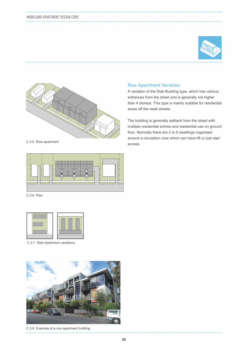
C.3.8 Example of a row apartment building
C.3.6 Plan
C.3.5 Row apartment
Row Apartment Variation
A variation of the Slab Building type, which has various entrances from the street and is generally not higher than 4 storeys. This type is mainly suitable for residential areas off the retail streets.
The building is generally setback from the street with multiple residential entries and residential use on ground fl oor. Normally there are 2 to 6 dwellings organised around a circulation core which can have lift or just stair access.
C.3.7 Slab Apartment variations

PART C BUILDING TYPE
21
C.4 TOWER BUILDING
C.4.1 Tower Apartment
C.4.3 Section
C.4.2 Plan
Tower Building type is a vertically proportioned building with a number of dwellings arranged around a central core. The building is a free standing element with a podium which defi nes the street wall.
Key characteristics
• Tall and slim built form• Generally a podium defi nes the street wall height
and relationship with the street• The podium has zero ground and street wall
setback to the primary street. The upper levels of the tower are setback to maximise light and view.
• Light and outlook from all four sides• Internal layout is organised around a central
circulation core
Where to use
The building type is best used where - • the lots are large enough to provide an outlook
on all four sides with appropriate building separation
• an existing or preferred context is a high density urban area
• a strong urban form or landmark is desired and is consistent with structure plan
• ideally suited for corner locations or on lots with more than one street frontage
C.4.4 Example of a tower apartment
22
MORELAND APARTMENT DESIGN CODE
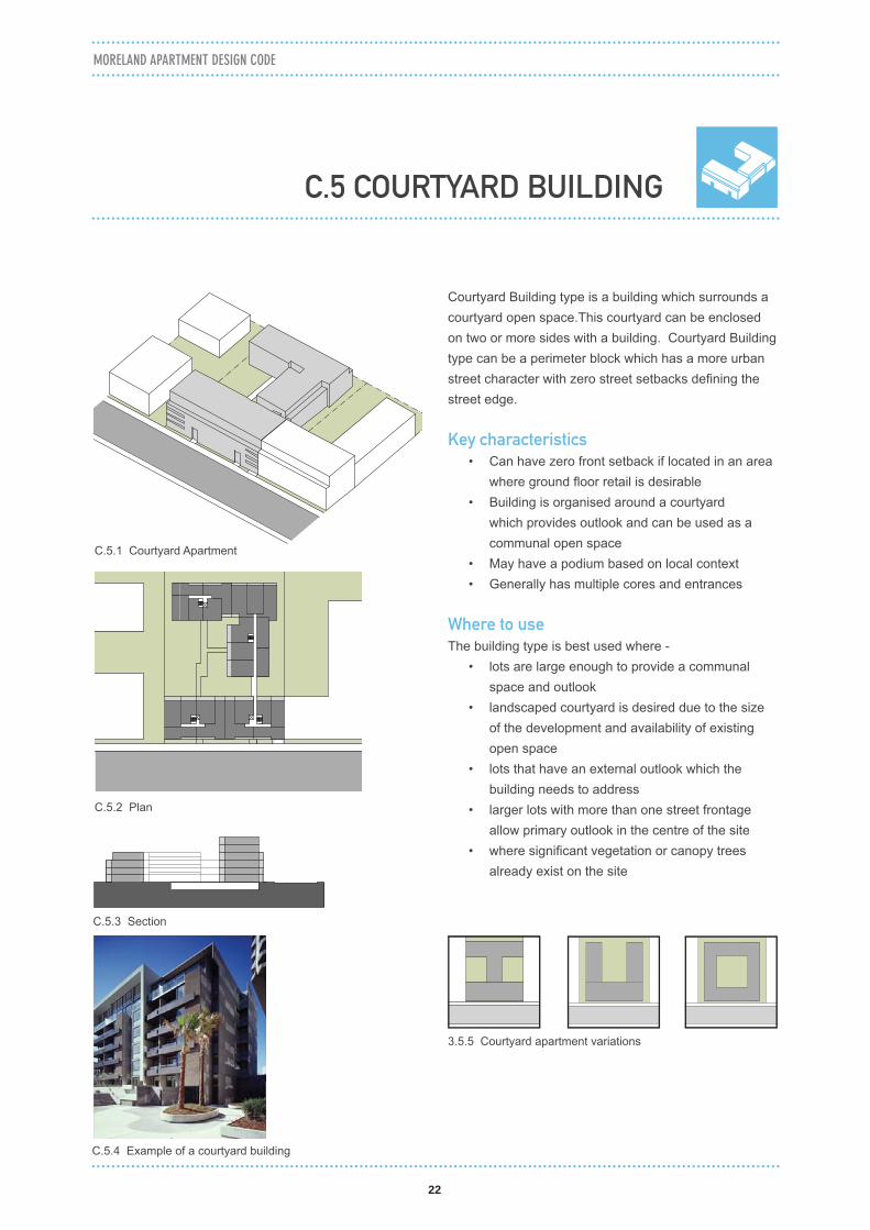
C.5.1 Courtyard Apartment
C.5.2 Plan
C.5.3 Section
C.5.4 Example of a courtyard building
Courtyard Building type is a building which surrounds a courtyard open space.This courtyard can be enclosed on two or more sides with a building. Courtyard Building type can be a perimeter block which has a more urban street character with zero street setbacks defi ning the street edge.
Key characteristics
• Can have zero front setback if located in an area where ground fl oor retail is desirable
• Building is organised around a courtyard which provides outlook and can be used as a communal open space
• May have a podium based on local context• Generally has multiple cores and entrances
Where to use
The building type is best used where - • lots are large enough to provide a communal
space and outlook• landscaped courtyard is desired due to the size
of the development and availability of existing open space
• lots that have an external outlook which the building needs to address
• larger lots with more than one street frontage allow primary outlook in the centre of the site
• where signifi cant vegetation or canopy trees already exist on the site
C.5 COURTYARD BUILDING
3.5.5 Courtyard apartment variations

PART C BUILDING TYPE
23
C.6.1 Hybrid Building which combines tower building, slab building and row building
C.6.2 Plan
C.6.3 Section
C.6.4 Example of a hybrid of slab apartments and row apartments
Hybrid Building type is a combination of two or more building types on a large development site. The combination is a result of site specifi c conditions and size of the site.
Key Characteristics
• a mixture of building forms and architectural expression
• may have a zero ground level setbacks or side setback based on context
• generally has more than one street frontage
Where to use
This building type is mainly used -• on larger site which have potential for multiple
buildings in various combinations• for sites with different edge conditions requiring a
different type or approach for each frontage• where a variety of dwelling types is desired• where signifi cant vegetation or mature canopy
trees already exist on the site
C.6 HYBRID BUILDING

24
MORELAND APARTMENT DESIGN CODE

25
PART D
ASSESSMENT PROVISIONS

26

27
N
N N
N N
PART D ASSESSMENT PROVISIONS
Objectives
• To balance optimum solar orientation with contextually responsive design to the public realm.
Standards
• The site layout should optimise solar access to the living areas of dwellings and open space areas.• The building(s) should create an identifi able address to the street and/or the public realm.• The building(s) should provide opportunities for passive surveillance of the public realm.• Building(s) adjoining a public park or reserve should:
– be substantially fronted by dwellings or open space. – clearly delineate private and public land to maximise outlook whilst avoiding a sense of privatisation of the
public park or reserve.
Decision Guidelines
Before deciding on an application, the Responsible Authority must consider:• Any structure plan, policy or planning provision applying to the area.• The opportunities and constraints of the site.• The design response.• The design guidelines.• The Sustainability Management Plan.
D.1.1 BUILDING ORIENTATION
D.1 PASSIVE DESIGN ELEMENT
Design Guidelines: Building Orientation
1.1.1 Building layout should balance the requirement to create an edge to the street and maximising solar access
1.1.2 Narrow lot buildings with East - West orientation require continuous central courtyards across multiple sites to provide larger combined internal open space
STR
EE
T
STR
EE
T
STR
EE
T
STR
EE
T

28
Minimum building separation (measured from property boundary)
Living/Main balcony outlook to boundary line Bedroom outlook to boundary line
Up to 4 storeys/12 metres 6 metres 3 metres
5-8 storeys (12-25m high) 5-8 storeys /up to 25 metres
9 metres 4.5 metres
9+ storeys/over 25 metres 12 metres 6 metres
Objectives
• To provide adequate daylight to living rooms and bedrooms.• To provide opportunities for open space areas.• To ensure buildings are located and designed to reduce overlooking into habitable rooms and private open
space areas.• To provide a quality outlook for residents.• To ensure the equitable development opportunities of adjoining properties.
Standards
• The urban context report and design response should include an equitable development analysis to assess the implications for development opportunities and amenity impact within the application site and for adjoining sites.
• Building separation distances should comply with the Tables D.1.2.a, D.1.2.b, D.1.2.c. Separation between buildings is measured from glazing line to glazing line of habitable rooms or the external edge of any balcony, whichever is the lesser. These separation distances have a primary purpose to provide adequate access to daylight in living areas and bedrooms. Alternative design solutions may achieve that purpose with lesser separation distances.
NOTE: • Building separation is not required to the side or rear boundary where no outlook is proposed provided
it does not affect the reasonable development opportunity of the adjoining site.• Zero building separation applies on sites where a continuous street wall is encouraged under the
relevant place-based control.• Where existing dwellings have not incorporated access to daylight to habitable rooms on their own
site in accordance with the building separation standards, the building separation standards will only apply to new development to the extent necessary to achieve a comparable contribution (from a minimum of one metre and a maximum of three metres) of daylight into the habitable rooms of the proposed dwellings.
• The building separation requirements commence at the fi rst level of residential use.
MORELAND APARTMENT DESIGN CODE
D.1 PASSIVE DESIGN ELEMENT
D.1.2 BUILDING SEPARATION
Table D.1.2.a Building separation to adjacent properties

29
Minimum building separation
Living/Main balcony outlook Bedroom outlook
2 storeys (9 metres high) 0 metres (from boundary) 0 metres (from boundary)
3-8 storeys (up to 25 metres) 6 metres (from lane centre line) 3 metres (from lane centre line)
9+ storeys/over 25 metres 9 metres (from lane centre line) 6 metres (from lane centre line)
NOTE: • The building separation requirements commence at the fi rst level of residential use.
• The use of light wells for daylight should be minimised.• Where light wells are provided, they should:
– Provide daylight access to bedrooms only. – Be painted in a light refl ective colour. – Provide an opportunity for useable space at ground level. – Bedroom windows in separate dwellings that face light wells should be staggered to avoid direct
overlooking.
PART D ASSESSMENT PROVISIONS
Table D.1.2.b Building separation to a lane
Minimum building separation
Living/Main balcony outlook to Living/
Main balcony outlook
Bedroom outlook to bedroom outlook
Living/Main balcony outlook to bedroom
outlook
Living/Main balcony outlook to no
outlook
Bedroom outlook to no outlook
Up to 4 storeys/12 metres
12 m 6 m 9 m 6 m 3 m
5-8 storeys/up to 25 metres
18 m 9 m 13.5 m 9 m 4.5 m
9+ storeys/over 25 metres
24 m 12 m 18 m 12 m 6 m
Table D.1.2.c Building separation for buildings within sites
NOTE: • The building separation requirements commence at the fi rst level of residential use.

30
• Light wells should comply with the following area and minimum width:
Dwelling type Minimum area and dimension
Up to 4 storeys/12 metres 9m2 (minimum width 3m)
5-8 storeys/up to 25 metres 29m2 (minimum width 4.5m)
9+ storeys/over 25 metres 51m2 (minimum width 6m)
Table D.1.2.d Light well minimum areas and dimensions
NOTE: • The light well minimum areas and dimensions may need to be varied for buildings containing multiple
levels of non-residential uses.
Decision Guidelines
Before deciding on an application, the Responsible Authority must consider:• Any structure plan, policy or planning scheme provision applying to the area.• The opportunities and constraints of the site.• The design response.• The reasonable development opportunities of adjoining lots.• Whether existing dwellings have not reasonably incorporated access to daylight on their own site.• Whether technical analysis demonstrates that separation distances of less than the benchmarks in the
standard meet daylight performance requirements.• The design guidelines.• The Sustainability Management Plan.
MORELAND APARTMENT DESIGN CODE

31
PART D ASSESSMENT PROVISIONS
Design Guidelines : Building Separation
Building Separation to adjacent property (living room to boundary)
Building Separation within sites (living room to bedroom)
Neighbour’s future development potential
1.2.3 Building separation allows fl exibility and different design outcomes depending on the type of outlook
1.2.5 Space created by building separation used as communal open space
1.2.1 Building separation for living/main balcony outlook 1.2.2 Building separation for bedroom outlook
Living/Main balcony outlookBedroom outlookNo outlook
KEY:
18m 18m
24m
12-2
5m25
+m
24m
12m
9m
(5-8
sto
reys
)(9
+ st
orey
s)
18m 18m12m 12m
12m 12m9m 9m
12m
12-2
5m25
+m
12m
6m
4.5m
(5-8
sto
reys
)(9
+ st
orey
s)6m 6m
9m 9m6m 6m
12m 12m
12m
6m
(4 s
tore
ys)
6m 6m
12m
3m
(4 s
tore
ys)

32
MORELAND APARTMENT DESIGN CODE
Design Guidelines : Light Well
lengthwidth
area
ground level of the light well should be accessible via a door and can be converted into a landscaped area
1.2.6 Minimum light well size
bedroom windows be staggered to avoid overlooking
1.2.9 Consolidation of light wells into a larger courtyard provides a more meaningful size of open space as a source of light. This will also result in better apartment layout with more useful internal space
1.2.8 Building design which relies on small light wells creates bedrooms with insuffi cient light
1.2.8 Size of light well increases as it goes higher to allow adequate light to the bottom apartment units
9m2 29m2 51m2
min.dimension 3m min.dimension 4.5m min.dimension 6m
Up to 4 storeys/12 metres
5-8 storeys/up to 25 metres
9+ storeys/over 25 metres

33
PART D ASSESSMENT PROVISIONS
D.1.3 DAYLIGHT ACCESS
D.1 PASSIVE DESIGN ELEMENT
Objectives
• To ensure adequate daylight to dwellings.
Standards
• Access to natural light in habitable rooms is to be principally achieved by compliance with Standard D.1.2 Building separation.
• The following minimum ceiling heights, measured from fi nished fl oor level (FFL) to fi nished ceiling Level (FCL), should apply: – Retail and commercial uses: min. 3.3 metres. – Residential uses: min. 2.7 metres for habitable rooms, min 2.4 metres for non-habitable rooms. – Above ground car parks: min 3.3 metres at ground fl oor, min 2.7 metres above ground fl oor.
• Reliance on borrowed light to bedrooms is discouraged. Where provided it is confi ned to one bedroom dwellings only and should meet the following requirements: – An operable internal door to the light source that is a minimum of 25% of the fl oor area of the bedroom. – The light source contains full height external windows along the full width of the living room to allow
adequate daylight.• Living areas (comprising living rooms, dining areas and kitchens) should not exceed a depth of 8 metres.• All living rooms should have an external window that is open to the sky or a balcony that is open for at least
one third of its perimeter.• In battle-axe rooms the space providing access to daylight (which is not affected by any obstructions and is
clear to the sky) should have a maximum length of twice its width.• Buildings should provide windows to circulation corridors and lift lobbies to maximise daylight access.• Developments which do not provide ceiling heights of 2.7 metres (measured from fi nished fl oor level to
fi nished ceiling level) for habitable rooms should demonstrate that dwellings will receive adequate daylight access.
Decision Guidelines
Before deciding on an application, the Responsible Authority must consider:• Any structure plan, policy or planning provision applying to the area.• The opportunities and constraints of the site.• The design response.• The design guidelines.• Floor to ceiling height of habitable rooms and the extent of glazing.• The Sustainability Management Plan.

34
Operable internal door should be more than 25% of the bedroom area
Floor to ceiling and wall to wall external opening
Borrowed Light
Bedroom
Max. twice the width
Width
Battle Axe Bedroom
West OrientationNorth Orientation
Light Shelves
MORELAND APARTMENT DESIGN CODE
Design Guidelines : Battle Axe Rooms and Borrowed Light Bedroom
1.3.2 Apartment with borrowed light is a poor outcome, when it is unavoidable it should be arranged according to the diagram
1.3.1 The maximum length of the battle axe bedroom handle should not exceed twice the width of the handle to achieve minimum daylight standard to the bedroom
Battle Axe (Saddle Back) Bedroom
1.3.4 Louvred screens on west facing windows reduce sun penetration
1.3.5 Light shelves allow light to disperse further in the room
1.3.3 Horizontal louvres on the north facing windows allow winter sun but block summer sun
Design Guidelines : Optimising Daylight Access
Design solutions can be used to optimise daylight access to habitable room’s window.
Borrowed Light Bedroom
35
Mid-summer
Mid-winter
Loft/Mezzanine
Minimum fl oor to ceiling height
min. 2.7m
min. 2.7m
min. 2.7m
min. 3.3m
min. 3.3m
Residential (Loft)
Residential
Residential
Residential
Commercial
Commercial
Car parking(Basement)
min. 2.4m
MidwinterMidsummer
MidwinterMidsummer
2.4
met
res
2.7
met
res
5.9 m 1.6 m
4.9 m 1.3 m
Car parking(Ground Floor)
PART D ASSESSMENT PROVISIONS
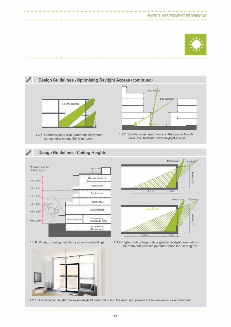
1.3.7 Double storey apartments on the ground fl oor & lower level facilitate better daylight access
Design Guidelines : Optimising Daylight Access (continued)
1.3.6 Loft/mezzanine type apartment allow more sun penetration into the living room
1.3.8 Minimum ceiling heights for mixed-use buildings 1.3.9 Higher ceiling height allow greater daylight penetration in the room and provides potential space for a ceiling fan
Design Guidelines : Ceiling Heights
1.3.10 Good ceiling height maximises daylight penetration into the room and provides potential space for a ceiling fan
36
Length of breeze path should be less than 15m to ensure cross ventilation
Max
. roo
m d
epth
sho
uld
be le
ss th
an 5
m
Opening should be min.5% of fl oor area
Cross ventilated apartment
Single-sided ventilated apartment
MORELAND APARTMENT DESIGN CODE
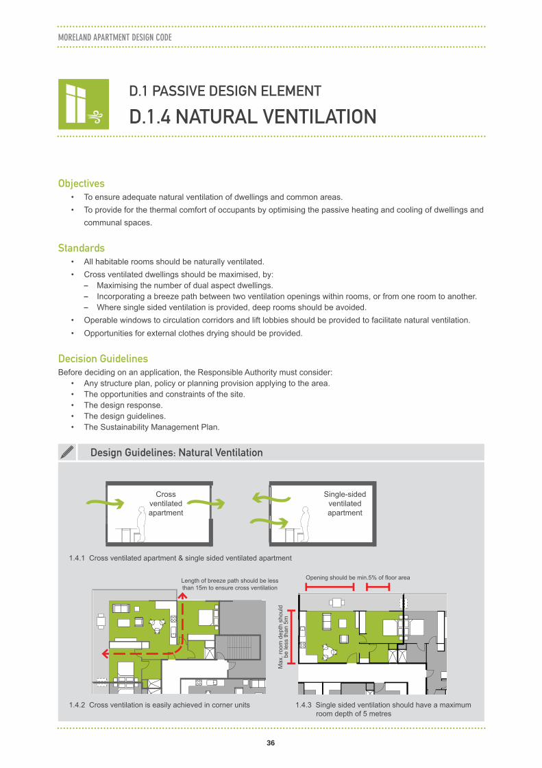
D.1.4 NATURAL VENTILATION
D.1 PASSIVE DESIGN ELEMENT
1.4.3 Single sided ventilation should have a maximum room depth of 5 metres
1.4.2 Cross ventilation is easily achieved in corner units
1.4.1 Cross ventilated apartment & single sided ventilated apartment
Objectives
• To ensure adequate natural ventilation of dwellings and common areas.• To provide for the thermal comfort of occupants by optimising the passive heating and cooling of dwellings and
communal spaces.
Standards
• All habitable rooms should be naturally ventilated.• Cross ventilated dwellings should be maximised, by:
– Maximising the number of dual aspect dwellings. – Incorporating a breeze path between two ventilation openings within rooms, or from one room to another. – Where single sided ventilation is provided, deep rooms should be avoided.
• Operable windows to circulation corridors and lift lobbies should be provided to facilitate natural ventilation.• Opportunities for external clothes drying should be provided.
Decision Guidelines
Before deciding on an application, the Responsible Authority must consider:• Any structure plan, policy or planning provision applying to the area.• The opportunities and constraints of the site.• The design response.• The design guidelines.• The Sustainability Management Plan.
Design Guidelines: Natural Ventilation

37
Loft apartment
Cross-over apartment
PART D ASSESSMENT PROVISIONS
1.4.4 Vertically, cross ventilation can be provided with cross-over apartment and loft apartment to improve fresh air intake; semi-basement creates a naturally ventilated carpark
1.4.7 Cross ventilation can be accommodated on dual aspect apartments on corners. Dual aspect apartment can be provided in the middle by having multiple light cores
Design Guidelines : Natural Ventilation (continued)
1.4.5 Cross-over apartment 1.4.6 Loft apartment
1.4.8 Cross ventilation can be provided using naturally ventilated corridors to reduce the breeze path to less than 15 metres

38
MORELAND APARTMENT DESIGN CODE
D.1 PASSIVE DESIGN ELEMENT
D.1.5 THERMAL COMFORT
Objectives
• To optimise provision of direct sunlight in winter while avoiding overheating in summer.• To ensure comfortable internal temperatures for occupants throughout the year.• To allow occupant control over thermal comfort.
Standards
• All dwellings should demonstrate that habitable room glazing receives adequate shading from summer sun and optimises solar access during winter. This could be via a combination of balconies, horizontal shading features and vertical shading features.
• Where external shading is not provided to northern, eastern or western facades, effective thermal comfort levels should be achieved by demonstrating a maximum cooling load for each dwelling using accredited energy rating software.
• Occupant control of the thermal environment should be facilitated. This could be through the provision of reversible ceilings, adjustable external shading devices, operable windows and zoning of mechanical heating and cooling systems where these are provided.
Decision Guidelines
Before deciding on an application, the Responsible Authority must consider:• Any structure plan, policy or planning provision applying to the area.• The opportunities and constraints of the site.• The design response.• The design guidelines.• The Sustainability Management Plan.
39
Scr
ee
nS
un
Sh
ad
ing
De
vice
sB
alu
str
ad
eB
alc
on
y Ty
pe
PART D ASSESSMENT PROVISIONS
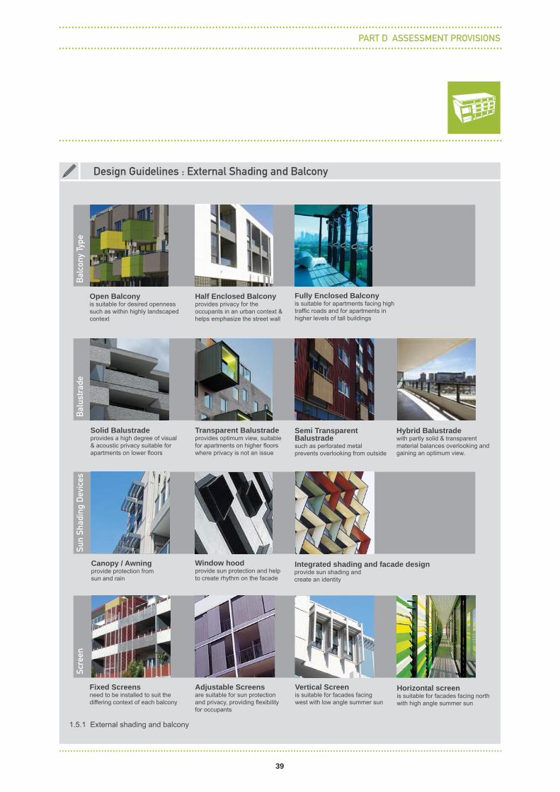
1.5.1 External shading and balcony
Design Guidelines : External Shading and Balcony
Open Balconyis suitable for desired openness such as within highly landscaped context
Half Enclosed Balcony provides privacy for the occupants in an urban context & helps emphasize the street wall
Fixed Screens need to be installed to suit the differing context of each balcony
Fully Enclosed Balcony is suitable for apartments facing high traffi c roads and for apartments in higher levels of tall buildings
Solid Balustrade provides a high degree of visual & acoustic privacy suitable for apartments on lower fl oors
Transparent Balustradeprovides optimum view, suitable for apartments on higher fl oors where privacy is not an issue
Semi Transparent Balustradesuch as perforated metal prevents overlooking from outside
Hybrid Balustrade with partly solid & transparent material balances overlooking and gaining an optimum view.
Vertical Screen is suitable for facades facing west with low angle summer sun
Window hoodprovide sun protection and help to create rhythm on the facade
Integrated shading and facade design
Horizontal screen is suitable for facades facing north with high angle summer sun
Adjustable Screens are suitable for sun protection and privacy, providing fl exibility for occupants
Canopy / Awning provide protection from sun and rain
provide sun shading and create an identity

40
MORELAND APARTMENT DESIGN CODE
D.2.1 DWELLING DIVERSITY
D.2 INTERNAL AMENITY AND FACILITIES
2.1.1 Most apartments are single aspect (no cross-ventilation) with two of them facing south
2.1.2 More than half of the apartments have dual aspects with no south facing unit
Having a mix of apartments also creates opportunity for better apartment amenity.
Design Guidelines : Dwelling Diversity
Objectives
• To provide a range of dwelling sizes.
Standards
• All developments should provide a range of dwelling sizes that includes the following types: – Studios. – 1 bedroom. – 2 bedrooms. – 3 bedrooms in developments of 50 or more dwellings.
Decision Guidelines
Before deciding on an application, the Responsible Authority must consider:• Any structure plan, policy or planning provision applying to the area.• The design guidelines.
2 BR
1BR 1BR
2 BR
2 BR 2 BR
2 BR
3 BR2 BR
2 BR
2BR 1BR 1BR
2 BR 2BR
1BR 1BR 1BR 1BR
3 BR2 BR

41
Dwelling type Size
Studio 37m2
1 bedroom dwelling 50m2
2 bedroom dwelling 65m2
3 or more bedroom dwellings 90m2
Table D.2.2 Minimum Dwelling Size Standards
PART D ASSESSMENT PROVISIONS
D.2.2 DWELLING SIZE AND LAYOUT
D.2 INTERNAL AMENITY AND FACILITIES
Objectives
• To ensure that dwellings are suitably sized and arranged to meet the needs of occupants and to enable fl exibility of use.
Standards
• Layout plans should illustrate the functionality and liveability of all proposed apartment types. These plans should also show typical furniture layouts.
• Dwellings should meet the minimum size standards in Table D.2.2.
Decision Guidelines
Before deciding on an application, the Responsible Authority must consider:• Any structure plan, policy or planning provision applying to the area.• The fl oor to ceiling heights of dwellings.• The size of the balcony.• The design guidelines.
42
MORELAND APARTMENT DESIGN CODE
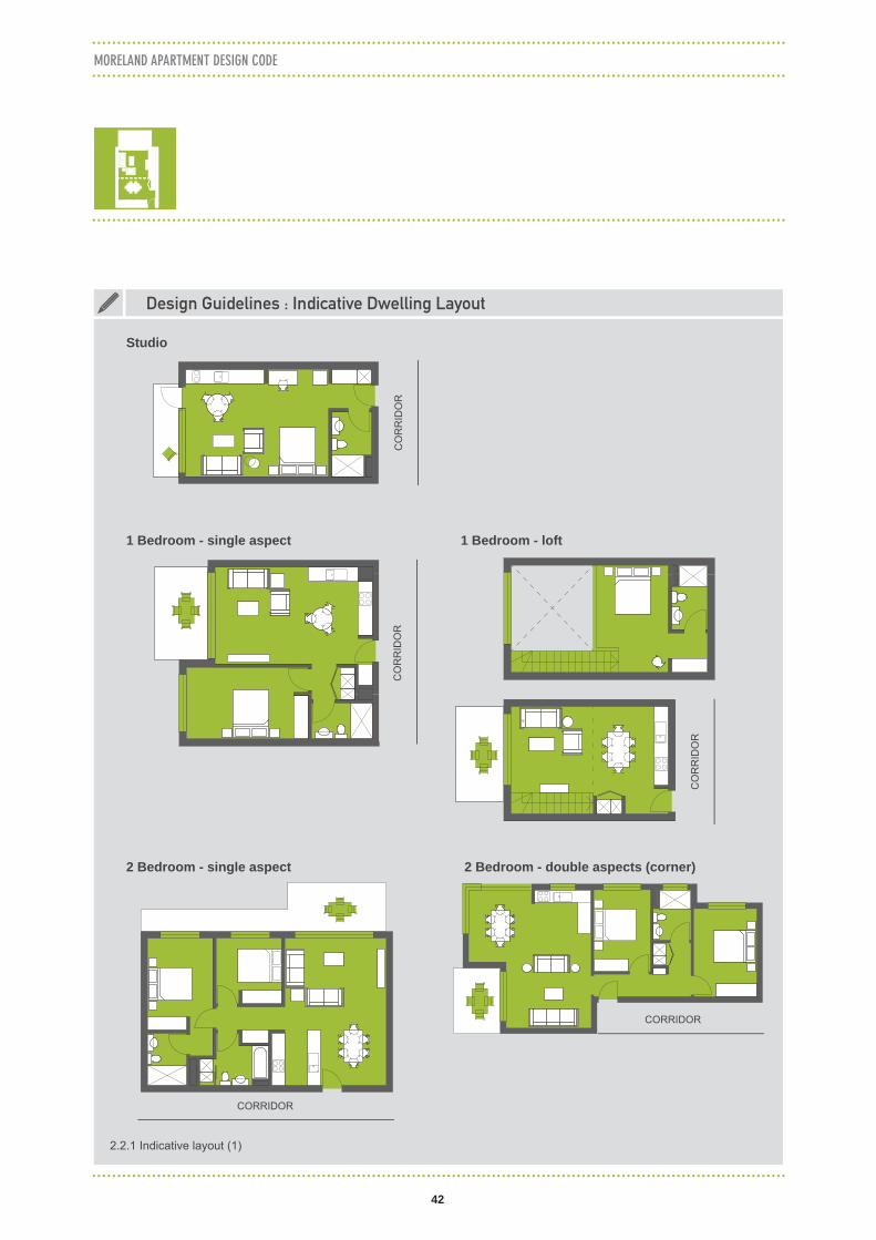
Design Guidelines : Indicative Dwelling Layout
Studio
1 Bedroom - single aspect 1 Bedroom - loft
2 Bedroom - single aspect 2 Bedroom - double aspects (corner)
CO
RR
IDO
R
2.2.1 Indicative layout (1)
CO
RR
IDO
RC
OR
RID
OR
CORRIDOR
CORRIDOR

43
PART D ASSESSMENT PROVISIONS
Design Guidelines : Indicative Dwelling Layout (continued)
2 Bedroom - double storey 2 Bedroom - cross-over
3 Bedroom - dual aspects
OTHER CROSS-OVER
UNIT
CO
RR
IDO
R
3 Bedroom - triple aspects
2.2.2 Indicative layout (2)
CO
RR
IDO
R
CORRIDOR
CO
RR
IDO
R

44
MORELAND APARTMENT DESIGN CODE
D.2.3 PEDESTRIAN ENTRY & CIRCULATION
D.2 INTERNAL AMENITY AND FACILITIES
Objectives
• To provide an identifi able street address.• To provide shelter to the entrances of buildings.• To ensure that circulation within buildings and access to dwellings and to communal areas is effi cient and
safe.
Standards
• Pedestrian entries should be clearly visible and identifi able from the public realm.• Avoid location of ramps across building frontages which impede opportunities for direct access to individual
tenancies.• Provide awnings to the pedestrian entrances to buildings.• The design of awnings should:
– Be continuous along retail/commercial and key pedestrian routes. – Complement the existing height, depth and form of existing awnings, where appropriate. – Have regard to any built form controls regarding the preferred character or existing character of the area. – Contribute to the legibility of the building and the amenity of the public realm. – Provide illumination. – Provide suffi cient protection from sun and rain.
• Distinguish the main entry to the apartment building from the entrances of any commercial and retail premises. • Provide clear separation between vehicle and pedestrian entries to buildings.• Provide a direct visual connection between the pedestrian entry and lift lobbies.• Provide generous corridor widths and ceiling heights no less than 2.7 metres, particularly in entry areas,
ground fl oor lobby and the waiting area around lifts.• Minimise corridor lengths to give short, clear sight lines and better orientation from within the building.• Natural light and ventilation should be provided to all communal circulation spaces.• Provide visible and attractive stairs from the entry level to a minimum of four fl oors to encourage stair use.• Long buildings should be designed with multiple cores instead of one core with a very long corridor to:
– Increase the number of entries along a street. – Provide for more cross-ventilated dwellings which are not limited by corridors.
• Where dwellings are arranged off a double loaded corridor, corridor length should not exceed 25 metres. Any corridors longer than 25 metres should be articulated with design solutions such as: – Utilising a series of foyer areas, as break space from the long corridor. – Providing windows at the end of a corridor, along the corridor or around lift lobby areas.
Decision Guidelines
Before deciding on an application, the Responsible Authority must consider:• Any structure plan, policy or planning provision applying to the area.• The opportunities and constraints of the site.• The design response.• The design guidelines.

45
Ground fl oor apartment entry through long corridor
Inadequate waiting area in front of the lift
Mailbox checking obstructs circulation route
No articulation zone between inside and outside
Direct entry to ground fl oor apartments from the street
Mailbox area clearly visible
Adequate space for waiting area in front of the lift
Staircase located to provide easy alternative to lift
Recess and covered area protects entry from rain
SECOND STREET
MAIN STREET
PART D ASSESSMENT PROVISIONS
2.3.1 Pedestrian entries into apartments should be direct, providing a clear view from the footpath and a suffi cient waiting area
2.3.2 Building with access to two parallel streets should provide direct access to the lift lobby from both streets
Design Guidelines : Building Circulation
2.3.3 Combination of staircase and entry will encourage residents to use staircase instead of lift; staircase which is visible from the street activates the street

46
MORELAND APARTMENT DESIGN CODE
Design Guidelines : Pedestrian Entry
2.3.4 The main entry to the building needs to be easily identifi able from the street and sheltered
2.3.5 Multiple pedestrian entrances for ground fl oor residential
2.3.8 Fire hydrant and other electrical services should be located perpendicular to the street to minimise large blank walls
2.3.9 Services such as fi re hydrant and electrical transformer should not be visually prominent to the street
2.3.6 Mail boxes which strengthen the sense of address for the building and activate the street frontage is a good outcome
2.3.7 Mail boxes which are not protected from weather, located away from the building entry and create confl ict between pedestrian and traffi c are considered a poor outcome

47
PART D ASSESSMENT PROVISIONS
2.3.10 Deep awnings should be designed to be half transparent to maximise daylight penetration to the window display and internal shop area
2.3.11 Transparent/semi-transparent awning improves daylight intake to the internal retail area while still protecting from rain; this awning is equipped with solar panels
Design Guidelines : Awning
2.3.12 Good awning design gives consideration to the context of the retail street
2.3.13 Awnings that do not relate to the context and do not provide weather protection are considered a poor outcome and should be avoided

48
MORELAND APARTMENT DESIGN CODE
D.2.4 ACOUSTIC PERFORMANCE
D.2 INTERNAL AMENITY AND FACILITIES
2.4.1 Solid balustrade for balconies reduces the noise transmitted into the apartment from busy road
Objectives
• To minimise noise transfer through the siting of buildings and building layout.• To minimise noise through apartment layout and acoustic treatments.
Standards
• Window and door openings should be oriented away from noise sources.• Noisy areas within buildings including building entries and doors should be located next to or above each
other and quieter areas next to or above quieter areas.• Storage, circulation areas and non-habitable rooms should be located to buffer noise from external sources.• Noise sources such as garage doors, driveways, service areas, plant rooms, building services, mechanical
equipment, active communal spaces and circulation areas should be located at least away from bedrooms.• Internal apartment layout should separate noisy spaces from quiet spaces, using a number of the following
design responses: – Rooms with similar noise requirements should be grouped together. – Doors should separate different use zones. – Wardrobes in bedrooms should be co-located to act as sound buffers.
• Where physical separation cannot be achieved noise confl icts should be resolved using the following design solutions: – Double or acoustic glazing. – Acoustic seals. – Use of materials with low noise penetration properties. – Continuous walls to ground level courtyards where they do not confl ict with streetscape or other amenity
requirements.
Decision Guidelines
Before deciding on an application, the Responsible Authority must consider:• The acoustic report (when required).• Any structure plan, policy or planning provision applying to the area.
Design Guidelines : Acoustic Performance

49
PART D ASSESSMENT PROVISIONS
2.4.3 Noisy areas such as living room and kitchen to be separated from quiet areas such as bedroom; laundry can be inserted in a separated room or combined within bathroom to reduce noise
2.4.2 Locate living spaces and particularly bedrooms away from noise source such as lifts, staircases and other plant rooms; use bathroom, storage or laundry as a buffer
Design Guidelines : Acoustic Performance (continued)
2.4.4 Adjacent typical units should be mirrored to group room functions and the type of noise.

50
Dwelling type Minimum Area Minimum depth
1 Bedroom apartments 8m2 2m
2 Bedroom apartments 10m2 2m
3 Bedroom apartments 12m2 2.5m
Table D.2.5 Private Open Space Minimum Size Standards
MORELAND APARTMENT DESIGN CODE
D.2.5 PRIVATE OPEN SPACE
D.2 INTERNAL AMENITY AND FACILITIES
2.5.1 Balcony with usable size provide high amenity for occupants
2.5.2 Ground fl oor or podium private terrace should be designed to provide landscaping and minimise overlooking
Objectives
• To provide functional and useable private open space areas for individual dwellings.
Standards
• Provide ground fl oor dwellings with access to landscaped open space having regard to the urban context.• Orient private open space to maximise solar access.• All dwellings should include a balcony with the following sizes and dimensions:
• The balcony should be extended to adjoin the living area to extend the living space.• Air conditioning units should not inhibit the use and amenity of private open space.
Decision Guidelines
Before deciding on an application, the Responsible Authority must consider:• The opportunities and constraints of the site.• The design response.• The design guidelines.• Any structure plan, policy or planning provision applying to the area.
Design Guidelines : Private Open Space

51
PART D ASSESSMENT PROVISIONS
2.5.3 Minimum size standard for private open space
2.5.4 A loggia type balcony is suitable for facades facing a noisy street or apartment on higher levels
2.5.5 Juliet balcony is suitable for apartments facing south which needs light penetration deeper into the room
2.5.6 Balcony which can be accessed from multiple rooms creates a larger space and allows variety of arrangement
Design Guidelines : Private Open Space (continued)
2.5.7 Ground fl oor private terrace should be generous in size to provide adequate buffer with communal/public area
Design balconies and terraces in response to the local climate and context thereby increasing the usefulness of the space.
2 m 2.5 m2 m2 m
Adjoininglivingspace
Adjoininglivingspace
Adjoininglivingspace
1 Bedroom Unit 2 Bedroom Unit 3 Bedroom Unit
min. 8m2 min. 10m2 min. 12m2

52
MORELAND APARTMENT DESIGN CODE
D.2.6 PRIVACY
D.2 INTERNAL AMENITY AND FACILITIES
Objectives
• To ensure a reasonable level of privacy to residents within a building and to residents in adjacent buildings.
Standards
• Overlooking should be minimised principally by compliance with D.1.2 Building separation.• Dwelling layouts should be designed to minimise direct overlooking into habitable spaces and private open
spaces instead of reliance on screening/obscuring measures that adversely impact on the quality of the outlook.
• Where direct views into private open space and habitable rooms are unavoidable, measures to reduce overlooking should be considered. Such measures may include level changes, landscaping, balconies, balustrades to balconies and screening devices such as horizontal or vertical fi ns.
Decision Guidelines
Before deciding on an application, the Responsible Authority must consider:• Any structure plan, policy or planning provision applying to the area.• The opportunities and constraints of the site.• The design response.• The design guidelines.
2.6.1 High screening in a small balcony is a poor outcome which reduces occupant’s internal amenity
2.6.2 Angled vertical louvres provide a view in particular direction while limiting in another direction
Design Guidelines : Overlooking from Balconies

53
PART D ASSESSMENT PROVISIONS
Design Guidelines : Overlooking from Balconies (continued)
2.6.3 Horizontal louvres allow looking in the distance and prevent looking down
2.6.5 Solid balustrades on the lower fl oors provide privacy for residents with upper level balconies which are not directly visible from the street can have transparent balustrades
2.6.6 Flexible sliding louvred screens provide privacy to suit building occupants and create a dynamic facade
2.6.4 Balcony planter box provides green outlook and limit looking down

54
MORELAND APARTMENT DESIGN CODE
2.6.8 Raised level for ground fl oor apartments provides privacy for the resident and casual surveillance to the street. It also allows natural ventilation into the semi-basement car park
2.6.7 Landscaping should be used to create privacy for ground fl oor residential dwellings
2.6.9 Ground fl oor residential with direct access from the street create sense of ownership and activate the street
2.6.10 Ground fl oor apartment directly adjacent to a park or other public space should provide direct access while providing clear separation between public and private
Design Guidelines : Residential Frontage

55
CORE
ADEQUATE DISTANCE
Adjustable screen for ground fl oor living room/bedroom near the communal path
Windows to the unit’s own terrace provide more privacy than a frontal window to communal courtyardCreate a recess area to distance the bedroom area away from the courtyard
Full wall separation between units improve terrace’s privacy
Plants create a buffer from courtyard to the ground fl oor apartments
Create adequate space for ground fl oor terrace
Avoid direct overlooking to the bedrooms from high traffi c areas such as apartment entry
Avoid direct over- looking from courtyard to private areas such as bedrooms and bathrooms
Direct entry from communal area to ground fl oor units
PART D ASSESSMENT PROVISIONS
2.6.12 Locating circulation cores at the corners helps create separation between balconies
2.6.13 Dwellings adjacent to a communal open space such as courtyard and passages require interface design to provide visual privacy
Design Guidelines : Visual Privacy within Development
2.6.11 Raised terrace and vegetation screen provides privacy for units facing internal courtyard

56
MORELAND APARTMENT DESIGN CODE
D.2 INTERNAL AMENITY AND FACILITIES
D.2.7 OPEN SPACE AND LANDSCAPE DESIGN
Objectives
• To provide and integrate open space within the site layout.• To integrate landscape design with the overall site layout and building design.• To enhance urban landscapes and respond to the existing or desired landscape context.• To enhance landscaping in the public realm.• To provide opportunities for landscaping that minimises the impact of the urban heat island effect and that
contributes to the micro-climate of the site.
Standards
• Solar access to open space areas should be maximised.• The landscape layout and design should:
– Protect any signifi cant landscape features including mature trees and vegetation. – Take into account the soil type, drainage patterns and other relevant conditions of the site. – Allow for intended vegetation without affecting the structural integrity of the building. – Identify opportunities for deep soil planting on large sites that is of suffi cient dimension to allow for the
planting of canopy trees. – Consider green walls and green roofs for thermal insulation and reduction in the urban heat island affect. – Identify opportunities to provide landscaping in the public realm.
• Impervious areas should be minimised through measures such as rain gardens, permeable pavements, grassed areas, vegetated green roofs and other on-site detention systems to reduce the volume storage required, cool the local area and provide irrigation to landscaping.
• Regular irrigation of vegetation should be provided using non-potable water where possible.• Landscapes should be designed to allow for effective on-going maintenance and to accommodate intended
performance.• Green roofs, green facades and other landscape structures are encouraged, particularly if areas for deep soil
planting are not provided.• Contribute to landscaping in the public realm in accordance with Moreland’s Streets Landscape Strategy
2012-2022, if appropriate.• A landscape design report prepared by a suitably qualifi ed landscape architect.
Decision Guidelines
Before deciding on an application, the Responsible Authority must consider:• Any structure plan, policy or planning provision applying to the area, including any Council street tree or public
park planting programs.• The opportunities and constraints of the site. • The design response.• The design guidelines.• The landscape architect report.

57
PART D ASSESSMENT PROVISIONS
2.7.1 Deep soil zones are areas of natural ground which allow planting of large trees on the site and have various environmental benefi ts such as reducing stormwater run-offs and urban heat island. Deep soil zone should be provided on sites larger than 2000m2 for a minimum of 5% of site area
Design Guidelines : Open Space and Landscape Design
2.7.4 Green walls can be used as a facade feature which improves building insulation in summer and winter, it will need careful consideration of irrigation and maintenance
2.7.2 Consolidate location of plant room, lift overrun and other roof equipment to maximise rooftop open space or roof garden
2.7.3 Green facades are usually created using creepers such as Boston ivy or creeping fi gs in planter boxes

58
MORELAND APARTMENT DESIGN CODE
D.2.8 COMMUNAL FACILITIES
D.2 INTERNAL AMENITY AND FACILITIES
2.8.1 Communal open space on ground fl oors can be used as community gardens in large developments
2.8.2 Communal open space should be directly accessible from the apartments fronting the space
Objectives
• To provide adequate communal facilities.
Standards
• All buildings with 20 or more dwellings should provide a communal open space area(s) of 2.5 square metres per dwelling.
• The effective use of roof space, podiums and light wells for communal open space is encouraged.• All communal spaces and facilities should be safe, accessible and, where possible, naturally lit and ventilated.• Communal open space should be:
– Consolidated into a recognisable and useable area. – Reasonably accessible from dwellings and from any internal communal open space area.
• Facilities should be provided for a range of age groups where size permits, incorporating some of the following elements: – Seating for individuals or groups. – Barbeque areas. – Play equipment or play areas. – Swimming pools, gyms or common rooms.
Decision Guidelines
Before deciding on an application, the Responsible Authority must consider:• Any structure plan, policy or planning provision applying to the area.• The opportunities and constraints of the site.• The design response.• The design guidelines.
Design Guidelines : Ground and Podium Communal Space

59
Garden bed
Pergola with solar hot water panels
Shed
BBQ
Laundry Lift
Sol
ar h
ot
wat
er
Clothes line
Landscaping
PART D ASSESSMENT PROVISIONS
2.8.3 Roof top gardens should have protected space such as pergolas and protective walls to create a more comfortable outdoor area
2.8.4 Rooftop communal space can be a space to show case sustainable features such as solar panels, energy meter display and promote social uses such garden beds
Design Guidelines : Roof Top Communal Space
2.8.5 Rooftop communal space layout plan which provides BBQ area, laundry, clothes drying area, communal garden and a shared tool shed
In high density areas roof tops provide a good opportunity to create a communal space.

60
Use Bicycle parking rate
Dwelling1 space per studio and 1 bedroom dwelling2 spaces per 2+ bedroom dwelling
Offi ce1 employee space per 200m2 gross fl oor area1 visitor space per 750m2 over 1000m2
Shop1 employee space per 300m2 gross fl oor area1 visitor space per 500m2 over 1000m2
Table D.2.9.1 Minimum Size Standards
MORELAND APARTMENT DESIGN CODE
D.2.9.1 BICYCLE & CAR PARKING
D.2 INTERNAL AMENITY AND FACILITIES/ D.2.9 SITE SERVICES
Objectives
• To ensure that bicycle and car parking areas and facilities are convenient, accessible and safe.• To ensure suffi cient bicycle facilities are provided.
Standards
Provision of bicycle facilities• Bicycle parking should be provided in accordance with the requirements of Table D.2.9.1.
• Reductions of the standard car parking rates in Clause 52.06 will be considered having regard to the level of provision of bicycle parking.
• Bicycle parking should be located as close as possible to the building entrance.• Bicycle parking should be accessible, safe and secure.• Showers and change facilities should be provided in accordance with Clause 52.34.• Bicycle spaces should be designed in accordance with the design suggestions contained within The bicycle
parking handbook, Bicycle Network Victoria, October 2004, or as may be amended from time to time.• Appropriate signage directing cyclists to the visitor spaces should be provided in accordance with the
requirements of Clause 52.34-5.
Layout of car parking• Car parking should:
– Be reasonably close and convenient to the uses it serves. – Be secure and designed to allow safe and effi cient movements within the development. – Be well ventilated if enclosed. – Provide scope for the parking of motorcycles.
• Car park areas should be located in basement levels or, if located at or above ground, car parks should be concealed from view through the use of occupied tenancies (‘sleeved’ with other uses) or dwellings.
• When semi-basement car parking is proposed, the area should be naturally ventilated.• External car parks and vehicle accessways should be located at least 1.5 metres from the windows of
habitable rooms. This setback may be reduced to 1 metre where there is a fence at least 1.5 metres high or where window sills are at least 1.4 metres above the accessway.

61
PART D ASSESSMENT PROVISIONS
• Vehicle accessways be separated from pedestrian entry points.• Car parking areas should be designed to maximise safety, including clear lines of sight to lifts, stairs and exit
points, be well lit and clearly signed.
Decision Guidelines
Before deciding on an application, the Responsible Authority must consider:• Any structure plan, policy or planning provision applying to the area.• The opportunities and constraints of the site.• The design response.• The design guidelines.
2.9.3 Semi basement car parking should only be used in residential areas with landscaping to screen it. The raised ground fl oor provides privacy and naturally ventilated basement. The height of the basement above natural ground should not be more than 90 cm
2.9.1 Car parking should be located in the basement or if located above-ground should be sleeved from the public domain with other uses such as commercial or residential
2.9.2 In sites with main road frontages above ground parking should be located at the rear of the site, behind retail and commercial uses
Design Guidelines : Car Parking Interface

62
MORELAND APARTMENT DESIGN CODE
2.9.8 Higher ceiling heights for above ground car parking allows future retrofi tting of the space for other uses
Design Guidelines : Flexible Use
Future potentialExisting layout
CAR PARKING
RETAIL
COMMERCIAL
RETAIL
min. 2.7 mCeiling Heights
min. 2.7 m
min. 3.3 m
2.9.4 Poorly designed above ground car parking has a negative impact on public realm and reduces the passive surveillance of the street
2.9.5 Landscaping should be used to screen the semi-basement car parking
2.9.6 Multiple garage entries on ground fl oor do not activate the street and create confl ict between pedestrians and traffi c
2.9.7 Reduce the number of driveways with a single vehicle entry leading to rear communal car parking
Design Guidelines : Car Parking Interface (continued)

63
PART D ASSESSMENT PROVISIONS
2.9.9 Bicycle parking should be integrated into the ground fl oor or communal space design instead of in the basement
Design Guidelines : Integrated Bicycle Design

64
MORELAND APARTMENT DESIGN CODE
D.2.9.2 PRIVATE STORAGE SPACE
D.2 INTERNAL AMENITY AND FACILITIES/ D.2.9 SITE SERVICES
2.9.11 Storage space should be located within apartments, as dedicated storage rooms on each fl oor, or in the basement
Objectives
• To provide suffi cient and accessible storage for each dwelling.
Standards
• All dwellings should provide adequate storage for everyday household items.• Additional storage space should be provided as follows:
– 4m3 for Studio and 1 bedroom apartments. – 6m3 for 2 bedroom apartment. – 8m3 for 3 bedroom apartment.
• Storage space does not include bicycle or car parking.
Decision Guidelines
Before deciding on an application, the Responsible Authority must consider:• Any structure plan, policy or planning provision applying to the area.• The design guidelines.
Design Guidelines : Private Storage Space

65
PART D ASSESSMENT PROVISIONS
Objectives
• To ensure that the design of buildings provide for sustainable management facilities and services.
Standards
• Waste management systems should be designed to meet best practice standards outlined in ‘Guide to Best Practice Waste Management in Multi-Unit Developments’ (Sustainability Victoria October 2010 and as updated), giving considerations to any local requirements.
• A dedicated storage area(s) for separation, collection and recycling of waste with ease of access for all building occupants and waste collection contractors that is suffi ciently sized to accommodate various recyclables should be provided.
• Dedicated facilities should be provided for composting and green waste where opportunity exists for on-site disposal and reuse.
Decision Guidelines
Before deciding on an application, the Responsible Authority must consider:• Extent of compliance with Waste Management Plan.• Any structure plan, policy or planning provision applying to the area.
D.2.9.3 WASTE MANAGEMENT
D.2 INTERNAL AMENITY AND FACILITIES/ D.2.9 SITE SERVICES
66
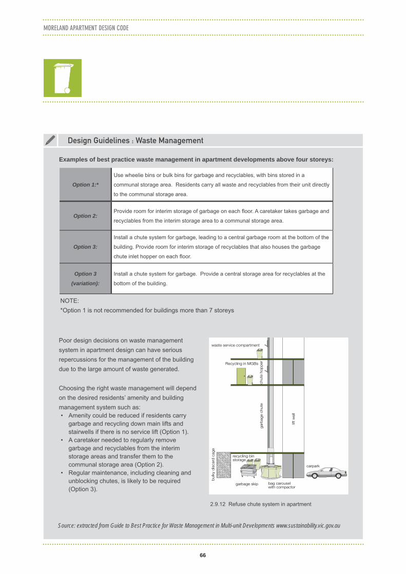
Examples of best practice waste management in apartment developments above four storeys:
MORELAND APARTMENT DESIGN CODE
Poor design decisions on waste management system in apartment design can have serious repercussions for the management of the building due to the large amount of waste generated.
Choosing the right waste management will depend on the desired residents’ amenity and building management system such as:• Amenity could be reduced if residents carry
garbage and recycling down main lifts and stairwells if there is no service lift (Option 1).
• A caretaker needed to regularly remove garbage and recyclables from the interim storage areas and transfer them to the communal storage area (Option 2).
• Regular maintenance, including cleaning and unblocking chutes, is likely to be required (Option 3).
lift
wel
l
carpark
gar
bag
e ch
ute
Recycling in MGBs
waste service compartment
bag carousel with compactor
garbage skip
recycling bin storage
chut
e ho
pp
er
bul
ky d
isca
rd c
age
2.9.12 Refuse chute system in apartment
Design Guidelines : Waste Management
Source: extracted from Guide to Best Practice for Waste Management in Multi-unit Developments www.sustainability.vic.gov.au
NOTE:*Option 1 is not recommended for buildings more than 7 storeys
Option 1:*
Use wheelie bins or bulk bins for garbage and recyclables, with bins stored in a
communal storage area. Residents carry all waste and recyclables from their unit directly
to the communal storage area.
Option 2: Provide room for interim storage of garbage on each fl oor. A caretaker takes garbage and
recyclables from the interim storage area to a communal storage area.
Option 3:
Install a chute system for garbage, leading to a central garbage room at the bottom of the
building. Provide room for interim storage of recyclables that also houses the garbage
chute inlet hopper on each fl oor.
Option 3
(variation):
Install a chute system for garbage. Provide a central storage area for recyclables at the
bottom of the building.

APPENDIX


1
MADC Checklist
1
Purpose of Checklist
Council adopted the Moreland Apartment Design Code (MADC) on 12 August 2015. It is now Council policy to require all applications for residential and mixed use development of fi ve or more storeys to comply with the Code. The Code is a performance based planning policy that contains discretionary standards and mandatory objectives. The purpose of this checklist is to provide applicants with a tool to check whether they comply with the Code’s standards and to provide an explanation where there is non-compliance with the Code’s standards. The completion of the checklist will assist Council’s urban planners to more expeditiously assess applications made under the Code.
It should be noted that some of the checklist requirements include some provisions from the Activity Centre Zone Schedule 1 applying in the Coburg Activity Centre and Design and Development Overlays Schedules 18, 19 and 20 applying to the Brunswick Activity Centre. These have been included in the checklist to enable a brief assessment of the proposal against key criteria relation to building height, street wall heights, upper level setbacks and interface to residential areas.
Application Details
Property address
Applicant name
Lodgement date
Application No. (office use only)
Number of dwellings
Site area
Density (number of dwelling/site area in hectare)

2
MORELAND APARTMENT DESIGN CODE
2
Activity Centre Zone/Design and Development Overlay Requirements
Metres Storeys Applicant Comments Officer Comments
Building height
Planning scheme height
Proposed height
Street wall
Planning scheme wall height N/A
Proposed street wall height N/A
Upper level setbacks
Planning scheme upper level setbacks N/A
Proposed upper level setbacks N/A
Residential interface
Planning scheme requirement N/A
Proposed interface N/A
Note: Please refer to the relevant section of the ACZ schedule and DDO to ascertain requirements
D.1.1 Building Orientation
Yes/No Applicant Comments Officer Comments
Site layout should optimise solar access to living areas and open space areas
Buildings should create an identifiable street address and/or to the public realm
Building should provide opportunities for passive surveillance to public realm
Buildings adjoining a public park or reserve should:
Be substantially fronted by dwellings or open space
Clearly delineate private and public land to maximise outlook whilst avoiding a sense of privatisation

3
MADC Checklist
3
D.1.2 Building Separation A. To Adjacent Properties
Living/main balcony
outlook to boundary
Bedroom outlook to boundary
Yes/No Applicant Comments Officer Comments
Up to 4 storeys/12 metres
6 m 3 m
1st side boundary
2nd side boundary
Rear boundary*
5-8 storeys/up to 25 metres
9 m 4.5 m
1st side boundary
2nd side boundary
Rear boundary*
9+ storeys 12 m 6 m
1st side boundary
2nd side boundary
Rear boundary*
Note: Where ACZ and DDO do not apply
B. To Laneways Living/main
balcony outlook
Bedroom outlook Yes/No Applicant Comments Officer Comments
2 storeys (9 m high) 0 m (from boundary)
0 m (from boundary)
3-8 storeys (up to 25 m) 6 m (from lane centre)
3 m (from lane centre)
9+ storeys (over 25 m) 9 m (from lane centre)
6 m (from lane centre)
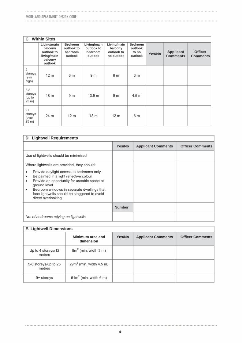
4
MORELAND APARTMENT DESIGN CODE
4
C. Within Sites Living/main
balcony outlook to living/main
balcony outlook
Bedroom outlook to bedroom outlook
Living/main outlook to bedroom outlook
Living/main balcony
outlook to no outlook
Bedroom outlook
to no outlook Yes/No Applicant
Comments Officer
Comments
2storeys (9 m high)
12 m 6 m 9 m 6 m 3 m
3-8storeys (up to 25 m)
18 m 9 m 13.5 m 9 m 4.5 m
9+storeys (over 25 m)
24 m 12 m 18 m 12 m 6 m
D. Lightwell Requirements
Yes/No Applicant Comments Officer Comments
Use of lightwells should be minimised
Where lightwells are provided, they should:
Provide daylight access to bedrooms only Be painted in a light reflective colour Provide an opportunity for useable space at
ground level Bedroom windows in separate dwellings that
face lightwells should be staggered to avoid direct overlooking
Number
No. of bedrooms relying on lightwells
E. Lightwell Dimensions
Minimum area and dimension
Yes/No Applicant Comments Officer Comments
Up to 4 storeys/12 metres
9m2 (min. width 3 m)
5-8 storeys/up to 25 metres
29m2 (min. width 4.5 m)
9+ storeys 51m2 (min. width 6 m)

5
MADC Checklist
5
D.1.3 Daylight Access
Yes/No Applicant Comments Officer Comments
Compliance with building separation
Minimum floor to ceiling heights:
Retail/office: 3.3 m Car parks:
Ground floor: 3.3 m Above ground floor: 2.7 m
Residential: Habitable rooms: 2.7m Non-habitable rooms: 2.4m
Reliance on borrowed light is discouraged. Where provided it is confined to one bedroom dwellings only and should meet the following requirements:
An operable internal door 25% of the floor area of the bedroom
Light source contains full height external windows along full width of living room
Living areas not to exceed 8 metres depth
All living areas should have an external window that is open to the sky or a balcony that is open for at least one third of its perimeter
Battle-axe dimensions have a maximum length of twice its width
Provision of windows in corridors/lift lobbies
Number
No. of bedrooms with borrowed light

6
MORELAND APARTMENT DESIGN CODE
6
D.1.4 Natural ventilation
Yes/No Applicant Comments Officer Comments
All habitable rooms should be naturally ventilated
Cross ventilation should be maximised by:
Maximising number of dual aspect dwellings Incorporating a breeze path between two
openings within rooms or from one room or another
Avoidance of deep rooms for single-sided rooms
Operable windows to circulation corridors and lift lobbies
External clothes drying
Number
No. of dual aspect dwellings
D.1.5 Thermal comfort
Yes/No Applicant Comments Officer Comments
External shading:
North East West
Where external shading not provided, effective thermal comfort levels to be achieved by demonstrating a maximum cooling load for each apartment
Provision for occupant control to be facilitated
D.2.1 Dwelling Diversity
Number Applicant Comments Officer Comments
No. of dwellings
1 bedroom
2 bedroom
3+ bedroom

7
MADC Checklist
7
D.2.2 Dwelling Size and Layout
Proposed (Average)
Applicant Comments Officer Comments
Studio - 37m2
1 bedroom - 50m2
2 bedroom - 65m2
3+ bedroom - 90m2
D.2.3 Pedestrian Entry and Circulation
Yes/No Applicant Comments Officer Comments
Entries
Clearly visible and identifiable from public realm
Avoid location of ramps across frontages
Distinguish main entry to apartments and entries to any retail or office entries
Provide clear separation between vehicle and pedestrian entries
Provide a direct visual connection between pedestrian entries and lift lobbies
Awnings
Continuous along commercial areas
Complementary to existing awnings
Meet any built form requirements
Contribute to the legibility of buildings
Provide illumination
Provide protection from sun and rain
Corridors
Generous widths and minimum 2.7 metre height
Minimise corridor lengths to give short, clear sightlines and better orientation
Provide natural light and ventilation
Provide visible and attractive stairs from entry level to first four levels
Long buildings to be designed with multiple cores
Long corridors to:
Increase the number of entries along a street
Provide cross-ventilation

8
MORELAND APARTMENT DESIGN CODE
8
Double-loaded corridors should not exceed 25 metres. Corridors exceeding 25 metres should provide:
A series of foyer areas or break space Windows at the end of the corridor, along
the corridor or around lift lobby areas
D.2.4 Acoustic performance
Yes/No Applicant Comments Officer Comments
Orient windows and doors from noise sources
Co-locate noisy areas within buildings and co-locate quieter areas
Locate storage, circulation areas and non-habitable rooms to buffer noise from external sources
Locate noise sources such as garage doors, driveways, service areas, plant room buildings, mechanical equipment away from bedrooms
Internal apartment layout should separate noise spaces from quiet spaces by:
Grouping together rooms with similar noise requirements
Using doors to separate different use zones Co-locating wardrobes to act as sound buffers
Where physical separation cannot be achieved
Use double or acoustic glazing Use acoustic seals Use materials with low noise penetration Use continuous walls to ground level
courtyards
D.2.5 Private Open Space
Proposed (Average)
Applicant Comments Officer Comments
1 bedroom 8m2 (2m min. width)
2 bedroom 10m2 (2m min. width)
3+ bedroom 12m2 (2.5m min. width)

9
MADC Checklist
9
D.2.6 Privacy
Yes/No Applicant Comments Officer Comments
Compliance with building separation
Minimisation of direct overlooking without reliance on screening
Use of measures where direct overlooking cannot be avoided
D.2.7 Open Space and Landscape Design
Yes/No Applicant Comments Officer Comments
Solar access to open space areas should be maximised
Landscaping layout
Protect any significant trees and vegetation
Take into account soil type, drainage patterns and other conditions
Ensure vegetation does not affect structural integrity
Identify opportunities for deep soil planting on large sites
Consider green walls and roofs
Identify opportunities for landscaping in public realm
Minimise impervious areas through measures such as rain gardens, permeable pavements, grassed areas, vegetated green roofs and other on-site detention systems
Use non-potable where possible for irrigation of vegetation
Allow effective on-going maintenance of landscaping
Use green roofs, green facades and other landscaping features if deep soil planting not provided
Contribute to landscaping public realm
Submit landscape design report

10
MORELAND APARTMENT DESIGN CODE
10
D.2.8 Communal Facilities
Yes/No Applicant Comments Officer Comments
Provide 2.5m2 per dwelling for communal facilities in buildings with 20 or more dwellings
Encourage effective use of roof space, podiums and light courts
Provide safe, accessible, naturally lit and ventilated
Communal open space should be:
Consolidated into a recognisable and useable area
Reasonably accessible from dwellings and from any internal communal open space
Provide for a range of facilities
D.2.9.1 Bicycle and Car parking
Applicant Comments Officer Comments
Car parking No.
No. of spaces required:
No. of spaces proposed:
Dispensation sought:
Bicycle parking No.
No. of spaces proposed:
Dwelling requirements 1 space per studio and 1 bedroom dwelling 2 spaces per 2+ bedroom dwelling Office requirements 1 employee space per 200m2 GFA 1 visitor space per 750 m2 over 1000m2
Shop requirements 1 employee space per 300 m2 GFA 1 visitor space per 500m2 over 1000m2
Bicycle Design Yes/No
Locate bicycle parking close to building entrance
Ensure bicycle areas are accessible, safe and secure
Shower and change facilities are provided
Bicycle areas are designed in accordance with design suggestions
Provision of signage

11
MADC Checklist
11
Car parking design Yes/No
Ensure close and convenient to areas they serve
Ensure car parks are secure, safe and efficient
Well ventilated if enclosed
Make provision for parking of motor cycles
Locate car parks within basements or conceal from uses if at ground or above ground
Locate car parks 1.5m from habitable rooms windows
Separate vehicle accessways from pedestrian entries
Maximise safety, provide clear lines of sight, be well lit and signed
Note: Car parking space is a requirement of Clause 52.06 not MADC
D.2.9.2 Private storage Space
Yes/No Applicant Comments Officer Comments
4m3 for studio/1-bedroom
6m3 for 2-bedroom
8m3 for 3-bedroom
D.2.9.1 Waste
Yes/No Applicant Comments Officer Comments
Design waste areas in accordance with Guide to Best Practice Waste Management in Multi-Unit developments
Provide dedicated storage areas for separation, collection and recycling of waste
Provide dedicated storage areas for composting and green waste where opportunity exists for on-site disposal and reuse


MADC Checklist
IMAGE CREDITS
Part C
C.1.4 Image by ROTHELOWMANC.2.4 Image by Breathe ArchitectureC.5.4 Image by Hayball
Part D
1.2.5 Image by Places Victoria
1.3.10 Image by Places Victoria
1.5.1 Image no. 2 and 9 by Hayball1.5.1 Image by no.3 by Ubertas Properties1.5.1 Images no. 5 and 15 by Jackson Clements Burrows (photography: John Gollings)
2.3.3 Image by Hayball
2.5.1 Image by dKO Architecture2.5.2 Image by Hayball
2.7.3 Image by Breathe Architecture
2.8.2 Image by Places Victoria2.8.5 Image by Breathe Architecture
2.9.9 Image by Hayball2.9.12 Image by Sustainability Victoria
All other photographs and illustrations by Moreland City Council