molding processes
TRANSCRIPT
Autodesk® Moldflow® Communicator 2012
Molding processes

Revision 1, 23 March 2011.
Contents
Molding processes. . . . . . . . . . . . . . . . . . . . . . . . . . . . . . . . . . . . . 1Chapter 1 Thermoplastic injection molding analysis types and technologies. . . . . . . . . . . 1
Overmolding. . . . . . . . . . . . . . . . . . . . . . . . . . . . . . . . . . . . . . . . . . . . . 2
Overmolding analysis . . . . . . . . . . . . . . . . . . . . . . . . . . . . . . . . . . . . 2
Thermoplastic Overmolding analysis types and analysis technologies. . . . . 3
Gas-assisted Injection Molding. . . . . . . . . . . . . . . . . . . . . . . . . . . . . . . . . 3
Gas-assisted injection molding analysis types and analysis technologies. . . . 5
Gas entrances. . . . . . . . . . . . . . . . . . . . . . . . . . . . . . . . . . . . . . . . . 5
Gas injection methods. . . . . . . . . . . . . . . . . . . . . . . . . . . . . . . . . . . . 6
Overflow wells—gas injection molding. . . . . . . . . . . . . . . . . . . . . . . . . 8
Co-injection molding overview. . . . . . . . . . . . . . . . . . . . . . . . . . . . . . . . . 9
Co-injection molding analysis types and analysis technologies. . . . . . . . . 10
Overcoming Co-injection molding problems. . . . . . . . . . . . . . . . . . . . 11
Injection-compression analysis. . . . . . . . . . . . . . . . . . . . . . . . . . . . . . . . 12
Injection-compression molding analysis types and analysis technologies. . 14
Injection-compression analysis process. . . . . . . . . . . . . . . . . . . . . . . . 14
Reactive Injection-compression Molding analysis types and analysis technologies. 16
Reactive Molding analysis types. . . . . . . . . . . . . . . . . . . . . . . . . . . . . . . . 16
iii

Reactive Molding analysis types and analysis technologies. . . . . . . . . . . . 17
Reactive Molding analysis. . . . . . . . . . . . . . . . . . . . . . . . . . . . . . . . . 17
Reactive Molding analysis process. . . . . . . . . . . . . . . . . . . . . . . . . . . 18
Reactive Molding analysis technical information. . . . . . . . . . . . . . . . . . 19
Microchip Encapsulation analysis. . . . . . . . . . . . . . . . . . . . . . . . . . . . . . . 19
Microchip Encapsulation analysis types and analysis technologies. . . . . . . 20
Microchip Encapsulation analysis types. . . . . . . . . . . . . . . . . . . . . . . . 20
Microcellular Injection Molding analysis. . . . . . . . . . . . . . . . . . . . . . . . . . 21
Microcellular injection molding analysis types and analysis technologies. . 23
Resin Transfer Molding. . . . . . . . . . . . . . . . . . . . . . . . . . . . . . . . . . . . . 23
RTM/SRIM analysis types and analysis technologies. . . . . . . . . . . . . . . . 24
Underfill Encapsulation analysis. . . . . . . . . . . . . . . . . . . . . . . . . . . . . . . 24
Underfill Encapsulation analysis types and analysis technologies. . . . . . . 25
Shape factor calculation for underfill encapsulation. . . . . . . . . . . . . . . . 25
Multiple-barrel Reactive Molding analysis types and analysis technologies. . . . 27
iv

1Molding processes
Once you have meshed your model, you are ready to select the molding process. It is importantthat you select the molding process that represents the real-case scenario that you are simulating.Once you have selected the molding process, the supported analysis sequences are updated.
Thermoplastic injection molding analysis types andtechnologies
The analysis technologies that are available to you depend on the analysis typethat you select. This table lists the available analysis technologies for a givenanalysis type.
Table 1: Thermoplastics Injection Molding process and analysis types
Analysis technologyAnalysis type
Fast Fill
Fill
Fill+Pack
Core shift (Process Settings option)
Standalone Pack
Fiber (Process Settings option)
Cool
Cooling Quality
Sink Mark
Warp
Birefringence (Process Settings option)
Stress
Shrink
1

Analysis technologyAnalysis type
Process Optimization
Design of Experiments
Molding Window
Gate Location
Runner Balance
Runner Adviser
Design Adviser
Venting (Process Settings option)
OvermoldingOvermolding is an injection molding process where two materials aremolded together. Types of overmolding include two shot sequentialovermolding, multi-shot injection molding or insert overmolding.
Multi-shot injection molding injects multiple materials into the cavityduring the same molding cycle. Insert overmolding uses a pre-molded insertplaced into the mold before injecting the second material. Two shotsequential overmolding is where the molding machine injects the firstmaterial into a closed cavity, and then moves the mold or cores to createa second cavity, using the first component as an insert for the second shotusing a different material.
Materials are usually chosen specifically to bond together, using the heatfrom the injection of the second material to form that bond. This avoidsthe use of adhesives or assembly of the completed part. It can result in arobust multi-material part with a high quality finish.
When designing an overmolded part, wall thicknesses of both the insertand the overmolded component should be as uniform as possible to ensurean even and robust bond. Avoid ribs and sharp corners to reduce flowproblems.
Overmolded parts take longer to cool than single shot injection moldedpart, and cooling systems are less effective. The insert acts as an insulatorand heat is less efficiently extracted from the part. However, optimisingthe cooling system can help reduce the cycle time.
Overmolding analysisAn Overmolding analysis is used to analyse two shot sequentiallyovermolded parts.
2 | Molding processes
Overmolding analyses consist of a two step process, where a Fill+Packanalysis is performed on the first cavity (first component stage), and thena Fill+Pack analysis or a Fill+Pack+Warp analysis is performed on theovermolding cavity (overmolding stage). The overmolding stage on thesecond cavity uses a different material from the first component stage. Asthe temperature of the insert, injected in the first component stage, is notuniform, mold and melt temperatures used in the overmolding stage areinitialized by the temperatures recorded at the end of the first componentstage.
NOTE: It is assumed that the material injected in the the first componentstage does not melt and flow when the second material is injected in theovermolding stage, even though the temperature does rise.
NOTE: Warp analyses on overmolded components on 3D models whichcontain part inserts, take into account the influence of contact betweenthe part inserts and the overmolded component.
Thermoplastic Overmolding analysis types and analysis technologiesThe following table shows the available analysis technologies for aThermoplastic Overmolding analysis type.
Table 2: Thermoplastic overmolding process and analysis types
Analysis TechnologyAnalysis Type
Fill
Fill+Pack
Fiber Fill+Pack
Overmolding
Warp
Venting (Process Settings option)
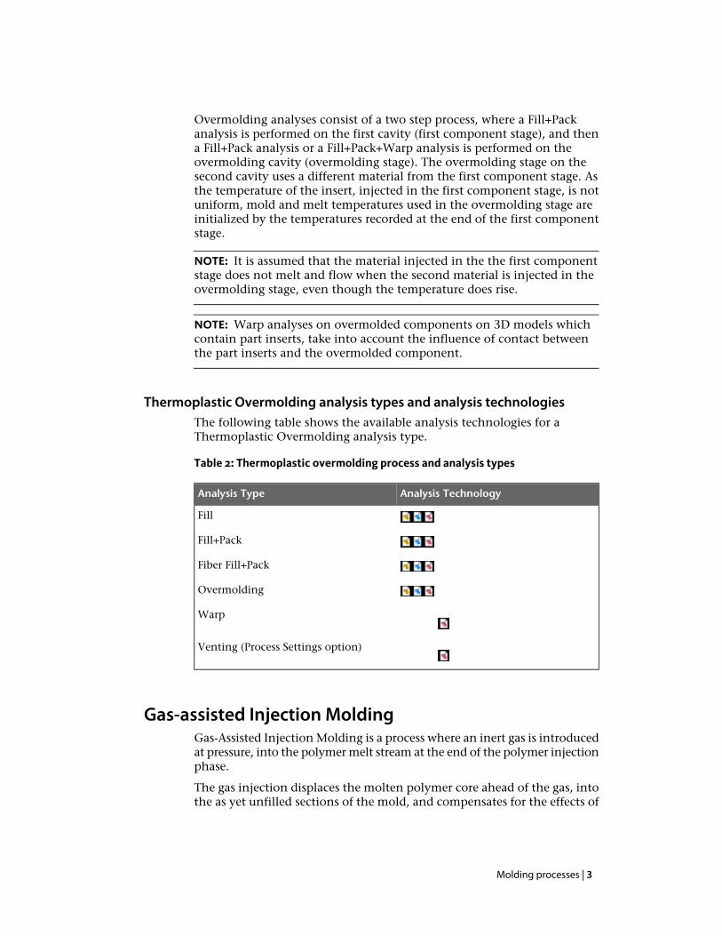
Gas-assisted Injection MoldingGas-Assisted Injection Molding is a process where an inert gas is introducedat pressure, into the polymer melt stream at the end of the polymer injectionphase.
The gas injection displaces the molten polymer core ahead of the gas, intothe as yet unfilled sections of the mold, and compensates for the effects of
Molding processes | 3
volumetric shrinkage, thus completing the filling and packing phases ofthe cycle and producing a hollow part.
Traditionally, injection molded components have been designed with arelatively constant wall thickness throughout the component. This designguideline helps to avoid major flaws or defects such as sink marks andwarpage. However, apart from the simplest of parts, it is impossible todesign a component where all sections are of identical thickness. Thesevariations in wall thickness result in different sections of the part packingdifferently, which in turn means that there will be differentials in shrinkagethroughout the molding and that subsequently distortion and sinkage canoften occur in these situations.
By coring out the melt center, gas injection molding enables the packingforce (which compensates for differential shrinkage) to be transmitteddirectly to those areas of the molding which require attention. Thisdramatically reduces differentials in shrinkage and thus the sinkage. Inaddition, the internal stresses are kept to a minimum, considerably reducingany distortion that may otherwise have taken place.
Maximum clamp pressures are normally required during the packing phaseof a molding cycle. This is due to the force which has to be exerted at thepolymer gate in order to pack melt into the extremities of the mold cavityin an effort to compensate for the volumetric shrinkage of the solidifyingmelt. In comparison to compact injection molding, gas injection moldingtypically has considerably shorter distance over which the solidifying meltis required to be packed because of the gas core. This means thatproportionally lower packing pressures are required to achieve the sameresults and in turn, lower machine clamp forces are required.
Gas injection allows cost effective production of components with:
■ Thick section geometry.■ No sink marks.■ Minimal internal stresses.■ Reduced warpage.■ Low clamp pressures.
4 | Molding processes
Gas-assisted Fill+Pack analysis benefits
Gas-assisted Fill+Pack analysis provides you with the ability to study polymerand gas flow behavior within a part model and examine the influence thatdesign modifications make on both the polymer and gas flow paths.
Using this information, the design engineer will be able to optimize productdesign and accurately position polymer and gas injection points. Also toensure that the product specifications are met, utilizing the full capabilitiesof the gas injection molding process. Expensive tool modifications, longlead times and trial and error will also be kept to a minimum.
The process engineer will benefit from the program's capacity to examinethe effects that varying processing conditions will have on the componentand enable optimum processing conditions to be established prior to moldcommissioning.
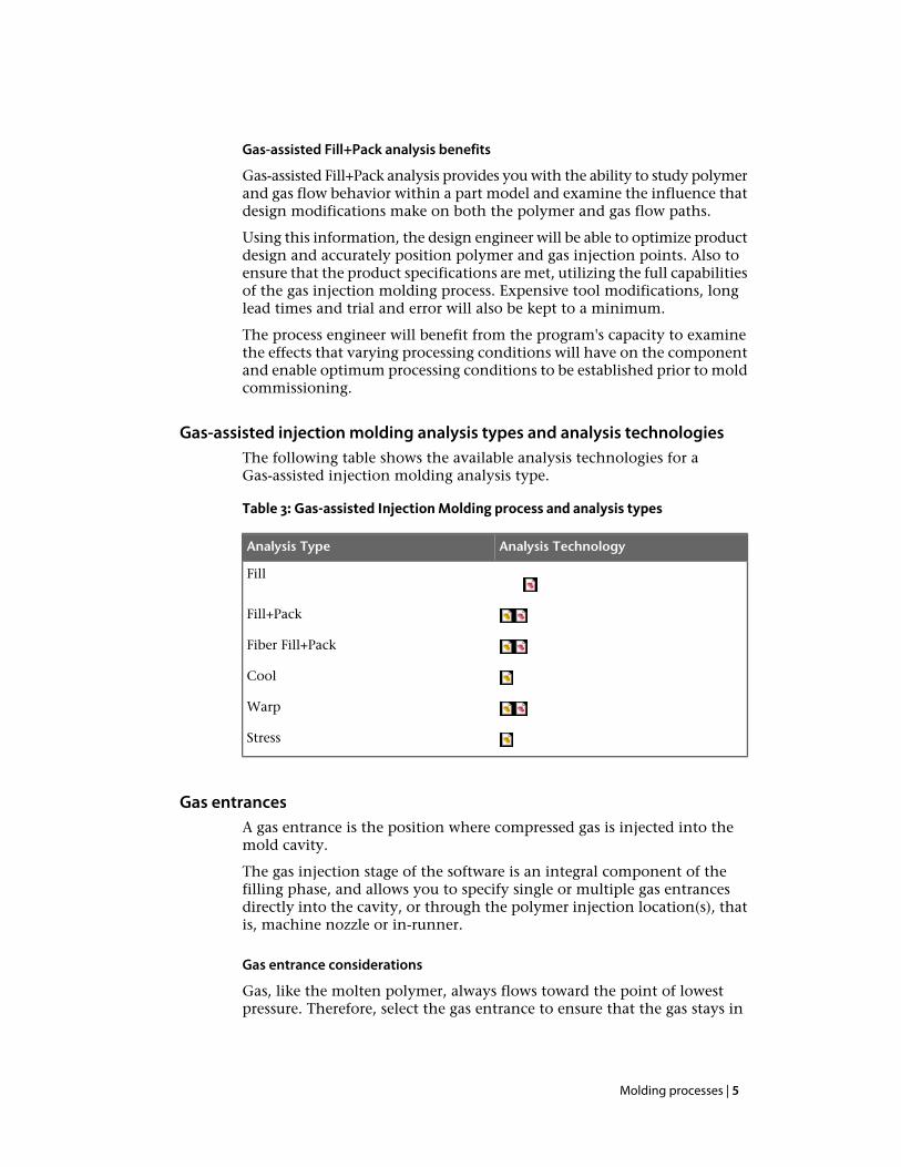
Gas-assisted injection molding analysis types and analysis technologiesThe following table shows the available analysis technologies for aGas-assisted injection molding analysis type.
Table 3: Gas-assisted Injection Molding process and analysis types
Analysis TechnologyAnalysis Type
Fill
Fill+Pack
Fiber Fill+Pack
Cool
Warp
Stress
Gas entrancesA gas entrance is the position where compressed gas is injected into themold cavity.
The gas injection stage of the software is an integral component of thefilling phase, and allows you to specify single or multiple gas entrancesdirectly into the cavity, or through the polymer injection location(s), thatis, machine nozzle or in-runner.
Gas entrance considerations
Gas, like the molten polymer, always flows toward the point of lowestpressure. Therefore, select the gas entrance to ensure that the gas stays in
Molding processes | 5

the gas channel, and that the area of lowest pressure is near the end of thegas channel.
Some of the more important questions to consider when setting gasentrances on your model are:
■ Polymer injection location(s).■ Along which route will the gas flow?■ How far will the gas penetrate?■ Will gas penetrate into the thin wall section?■ What will the channel and wall thickness be?■ Is the optimum part weight being achieved?■ Will sink marks be avoided?
As with all polymer melt flow analyses, geometry changes in one area canhave an effect on the flow characteristics in another section. This is evenmore significant with gas-assisted injection molding due to the sensitivitywith which the pressurized gas searches out and flows through the routeof least resistance until such a time as the cumulative resistance of the meltexceeds the pressure of the gas.
For this reason, changes to component geometries must not be looked atin isolation to one another. Due to the complexity of the problem this isonly feasible with the aid of a computer based simulation process.
Gas injection methodsDuring Gas-assisted injection molding, the gas can be injected into thepolymer melt either through the nozzle of the molding machine, or bydirect injection into the mold or into a runner.
This help topic outlines the advantages and disadvantages of each usingeach method.
6 | Molding processes
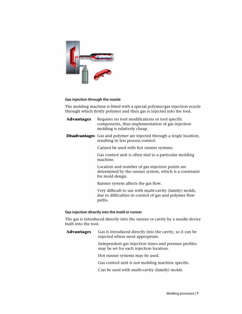
Gas injection through the nozzle
The molding machine is fitted with a special polymer/gas injection nozzlethrough which firstly polymer and then gas is injected into the tool.
Requires no tool modifications or tool specificcomponents, thus implementation of gas injectionmolding is relatively cheap.
Advantages
Gas and polymer are injected through a single location,resulting in less process control.
Disadvantages
Cannot be used with hot runner systems.
Gas control unit is often tied to a particular moldingmachine.
Location and number of gas injection points aredetermined by the runner system, which is a constraintfor mold design.
Runner system affects the gas flow.
Very difficult to use with multi-cavity (family) molds,due to difficulties in control of gas and polymer flowpaths.
Gas injection directly into the mold or runner
The gas is introduced directly into the runner or cavity by a needle devicebuilt into the tool.
Gas is introduced directly into the cavity, so it can beinjected where most appropriate.
Advantages
Independent gas injection times and pressure profilesmay be set for each injection location.
Hot runner systems may be used.
Gas control unit is not molding machine specific.
Can be used with multi-cavity (family) molds.
Molding processes | 7
Higher tooling costs.Disadvantages
Overflow wells—gas injection moldingIdeally, the placement and extent of gas channels should be controlled bysuitable modifications to the part geometry.
In cases where this does not provide sufficient control, overflow wells canbe used to increase gas penetration, or direct the gas into specific areas ofthe part.
An overflow well is a secondary cavity into which the gas can displacepolymer and thereby penetrate further into the part. Overflow wells providepaths of least resistance along which the gas will preferentially travel.Further control over gas flow can be achieved by opening and closing theoverflow wells at specific times by means of valve gates.
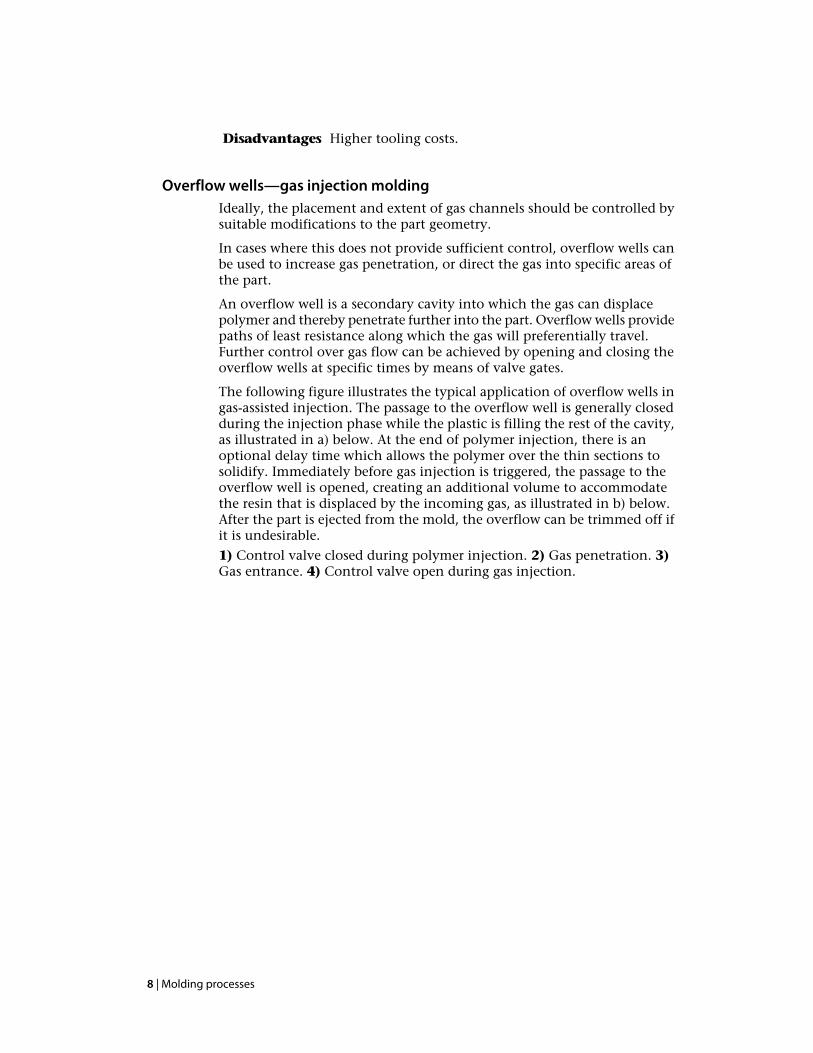
The following figure illustrates the typical application of overflow wells ingas-assisted injection. The passage to the overflow well is generally closedduring the injection phase while the plastic is filling the rest of the cavity,as illustrated in a) below. At the end of polymer injection, there is anoptional delay time which allows the polymer over the thin sections tosolidify. Immediately before gas injection is triggered, the passage to theoverflow well is opened, creating an additional volume to accommodatethe resin that is displaced by the incoming gas, as illustrated in b) below.After the part is ejected from the mold, the overflow can be trimmed off ifit is undesirable.
1) Control valve closed during polymer injection. 2) Gas penetration. 3)Gas entrance. 4) Control valve open during gas injection.
8 | Molding processes

Figure 1: Legend:
Overflow wells must be modeled with a defined volume. For Midplanemodels only, an overflow well with infinite volume can be simulated bysetting a venting location at the end node of the overflow well.
Co-injection molding overviewCo-injection molding involves injection of two dissimilar materials. Becauseof this, co-injection has some special advantages, as well as some potentialmolding problems. The Co-injection analysis helps you overcome thepotential problems and leverage the advantages, by helping to optimizeprocess control strategies and enhance part quality.
Co-Injection analysis simulates the sequential injection of skin and coreplastic materials. Sequential co-injection processes have two barrels andone nozzle in an injection molding machine.
(a) The skin plastic is injected into the mold first. (b) The core plastic thenis injected. (c) finally, the skin plastic is injected again, to purge the corematerial from the sprue .
Molding processes | 9

Figure 2: Co-injection process
The skin plastic is the material that is expected to be deposited on the cavitywall over the entire surface of the part. The core plastic displaces the skinplastic at the hot core, pushing it to fill the rest of the cavity. The endproduct is a sandwich-like structure, with the core plastic in the middleand the skin plastic on the surfaces of the part.
Co-injection molding takes advantage of a characteristic of injectionmolding called fountain flow. As the cavity is filled, the plastic at the meltfront moves from the center line of the stream to the cavity walls. Becausethe wall temperature is below the transition temperature (freezetemperature) of the melt, the material that touches the walls cools rapidlyand freezes in place. This provides insulating layers on each wall, throughwhich new melt makes its way to the melt front.
Advantages and applications
The advantages of this process are:
■ The combination of two material properties into one part.■ The maximization of the overall performance/cost ratio.
Examples of co-injection applications include:
■ The use of plastic regrind as the core material, while maintaining surfacefinish quality by using virgin plastic as the skin material.
■ The use of a core material that is thermally more stable, to increase thethermal resistance of a part.
■ The use of a high melt-flow index plastic as the core material, to reducethe overall clamp force.
Co-injection molding analysis types and analysis technologiesThe following table shows the available analysis technologies for aCo-injection molding analysis type.
10 | Molding processes

Table 4: Co-injection Molding process and analysis types
Analysis TechnologyAnalysis Type
Fill+Pack
Fiber Fill+Pack
Cool
Warp
Stress
Overcoming Co-injection molding problemsBecause Co-injection molding involves the injection of two dissimilarmaterials, there are some potential molding problems that may need to beovercome.
The biggest challenges in Co-injection molding are:
■ To determine the optimal ratio of skin material to core material.■ To determine the optimal time to switch from injection of skin material
to injection of core material.
The theoretical maximum amount of core plastic in a part is aboutsixty-seven percent by volume. However, it is very difficult to accomplishthis in an actual application, with complex part geometry. In practice,about thirty percent core plastic by volume can be achieved.
With an improper mold design or an insufficient amount of skin plastic,the core plastic may eventually deplete all the skin plastic injected aheadof it, and appear on the part surface. This undesirable “core surfacing”typically occurs at areas that fill last (where plastic has the longest flowlength).
Skin Polymer, Core Polymer
Molding processes | 11

Figure 3: Correct flow (above), Core Surfacing (below)
Using Co-injection to overcome potential molding problems
Co-injection analysis traces the spatial distribution of the skin and coreplastics throughout the cavity during the filling process. The analysisaccounts for the differences in material properties and in processingtemperatures of the skin and core plastics, as well as the mass, heat, andmomentum interactions between them. Co-injection provides informationthat designers and engineers use to qualitatively predict part performance,improve mold designs, and optimize process controls. In particular, it isan efficient tool for determining the best combination of skin and coreplastics, and the most appropriate switch-over time.
Injection-compression analysisThe Injection-compression molding process is an extension of conventionalinjection molding. After a pre-set amount of plastic melt is fed into an opencavity, it is compressed. The primary advantage of this process is the abilityto produce dimensionally stable, relatively stress-free parts, at a low clampforce. Injection-compression molding is sometimes called coining, stamping,compressive-fill, or hybrid molding.
Injection-compression simulates the following special characteristics of theInjection-compression molding process:
During this stage, the mold cavity thickness is designedto be larger than the target part thickness, in order to allow
Injectionphase
plastic to flow easily to the extremities of the cavity.Because the plastic flows easily, it can do so underrelatively low pressure and stress.
During or after filling, a compressive force reduces themold cavity thickness, forcing the resin into the unfilled
Compressionphase
portions of the cavity. This produces a more uniformpacking pressure across the cavity. This results in morehomogeneous physical properties and less molded-instresses compared to conventional injection molding.
12 | Molding processes
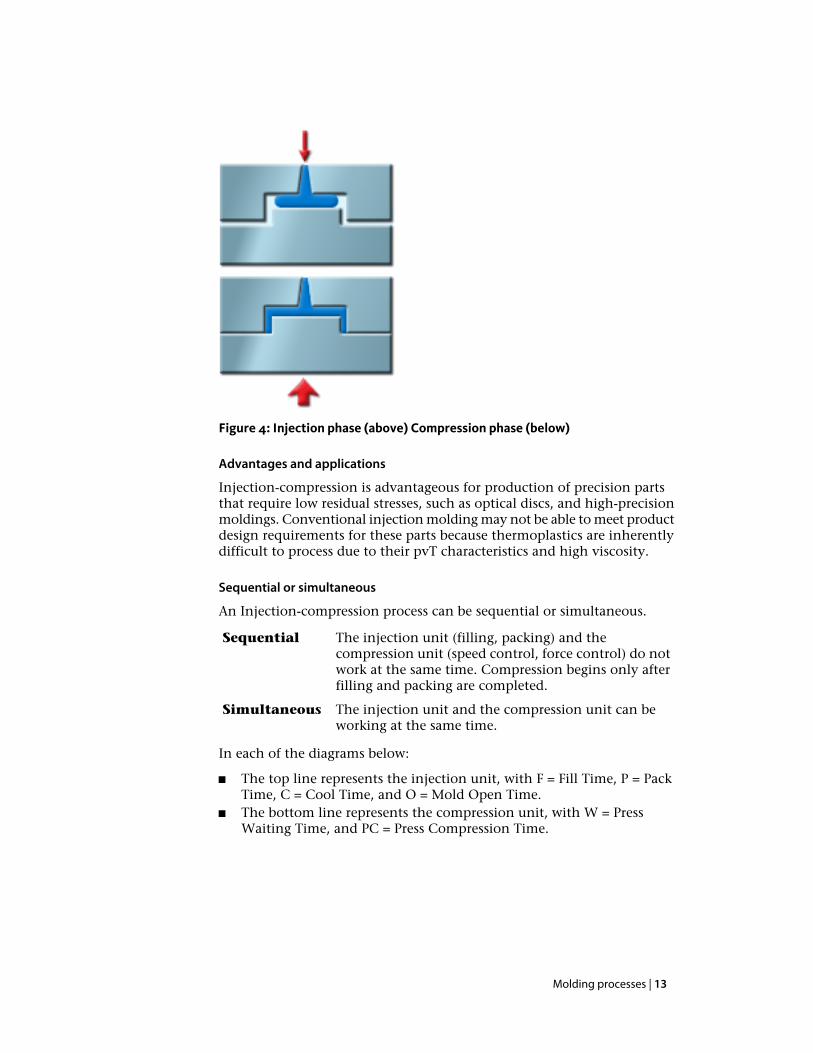
Figure 4: Injection phase (above) Compression phase (below)
Advantages and applications
Injection-compression is advantageous for production of precision partsthat require low residual stresses, such as optical discs, and high-precisionmoldings. Conventional injection molding may not be able to meet productdesign requirements for these parts because thermoplastics are inherentlydifficult to process due to their pvT characteristics and high viscosity.
Sequential or simultaneous
An Injection-compression process can be sequential or simultaneous.
The injection unit (filling, packing) and thecompression unit (speed control, force control) do not
Sequential
work at the same time. Compression begins only afterfilling and packing are completed.
The injection unit and the compression unit can beworking at the same time.
Simultaneous
In each of the diagrams below:
■ The top line represents the injection unit, with F = Fill Time, P = PackTime, C = Cool Time, and O = Mold Open Time.
■ The bottom line represents the compression unit, with W = PressWaiting Time, and PC = Press Compression Time.
Molding processes | 13

Figure 5: Sequential Injection-Compression
Figure 6: Simultaneous Injection Compression
There are no constraints in Injection-compression for a sequential orsimultaneous process in which the compression unit is under speed control.However, for a simultaneous process in which the compression unit isunder force control, the Injection-compression analysis may take longer.Even when the press force exceeds the press force used, the analysis willcontinue.
Injection-compression molding analysis types and analysis technologiesThe following table shows the available analysis technologies for aInjection-compression molding analysis type.
Table 5: Injection-compression molding process and analysis types
Analysis TechnologyAnalysis Type
Fill+Pack
Fiber Fill+Pack
Cool
Warp
Stress
Injection-compression analysis processAn Injection-compression analysis process involves injecting a volume ofplasticated melt into an open cavity and subsequently compressed.
Process Details
1 Oversized cavity. For Injection-compression molding, the cavitythickness is initially oversized by 0.5 to 10 mm more than the targetthickness; later the thickness will be reduced.
2 Injection. Plastic melt is injected into the cavity.
14 | Molding processes

3 Press waiting. Meanwhile, the press is moved to a pre-determinedposition. It will be stationary and stay in this position for a period oftime. This time period is called the press waiting time. The waiting timestarts when the melt injection begins and ends when the press beginsto move.
4 Compression. The compression stage starts when the press begins tomove. (The press is sometimes called the plunger, moving mold half,or moving platen.) The total press compression time includes the timeduring which compression is under speed control plus the time duringwhich the press is under force control.
5 Compression under speed control. In the press compression stage,the movement of the press in initially under speed control, specifiedby the press compression speed at incremental distances profile. Foreach incremental distance, the press moves at a constant speed. Thistype of movement continues until it reaches a pre-set press compressionforce.
6 Compression under force control. After the press force reaches thepre-set force, the press switches from speed control to force control.The press can keep moving forward, however, it will be in a constantforce control mode (pre-set force).
7 Stationary press. After the press compression phase is complete, thepress will stay in that position and remain stationary thereafter.
8 Press returns. When packing and cooling end and mold-openingbegins, the press begins to move backward.
Features
Injection Compression provides:
■ Independent control of the injection and compression units.■ Two-stage press control: speed control and force control.■ Open and close control for the polymer injection location and valve
gate.
Injection-compression helps you to:
■ Minimize the press force (clamp force) for compression.■ Minimize the injection pressure.■ Minimize shrinkage, warpage and residual stress.
NOTE: In this version of Injection-compression, the compression effect isapplied only to the triangular elements. In general, press force control needsmore computational time than press speed control.
Molding processes | 15
Reactive Injection-compression Molding analysis typesand analysis technologies
The following table shows the available analysis technologies for a ReactiveInjection-compression Molding analysis type.
Table 6: Reactive Injection-compression process and analysis types
Analysis TechnologyAnalysis Type
Fill+Pack
Reactive Molding analysis typesReactive Molding processes, also called thermoset molding processes, usethermoset materials.
Thermosets, unlike thermoplastics, are characterized by the following:
■ A chemical reaction during the molding process■ Cross-linked polymer structure■ Simultaneous polymerization and shaping during the molding process.
Processes
The Reactive Molding processes include the following:
■ Reaction Injection Molding (RIM)■ Structural Reaction Injection Molding (SRIM)■ Resin Transfer Molding (RTM)■ Multiple-barrel reactive molding (RIM-MBI)■ Thermoset injection molding■ Rubber injection molding■ Microchip Encapsulation■ Underfill Encapsulation
Advantages
The Reactive Molding analysis offers the following advantages:
■ Thermosets' cross-linked polymer structure generally imparts improvedmechanical properties and greater heat and environmental resistance.
■ Thermosets' typically low viscosity permits large and complex parts tobe molded with relatively lower pressure and clamp force than requiredfor thermoplastics molding.
■ Thermosets can be used in composite processes. For example, RTM andSRIM processes, which use a preform made of long fibers, offer a way
16 | Molding processes

to make high-strength, low-volume, large parts. Fillers and reinforcingmaterials can enhance shrinkage control, chemical and shock resistance,electrical and thermal insulation, and/or reduce cost.
Reactive Molding analysis types and analysis technologiesThe following table shows the available analysis technologies for a ReactiveMolding analysis type.
Table 7: Reactive Molding process and analysis types
Analysis TechnologyAnalysis Type
Fill+Pack
Warp1
Runner Balance
Venting (Process Settings option)
Reactive Molding analysisReactive Molding provides useful information to detect various moldingproblems and to optimize part, mold, and process design in an efficientand cost-effective way.
Reactive Molding can be applied to various processes that use reactive(thermoset) materials, including Reaction Injection Molding (RIM),Structural Reaction Injection Molding (SRIM), Resin Transfer Molding forfiber reinforced plastic (RTM), thermoset injection molding, rubbercompound injection molding, Microchip Encapsulation and UnderfillEncapsulation.
Reactive Molding analyses help to predict how the mold will fill with orwithout the presence of fiber reinforced pre-forms, avoid short shots dueto pre-gelation of the resin, highlight potential air trap or weld lineproblems, balance runner systems, select the proper molding machine size,and evaluate different reactive resins. The Reactive Molding analyses areintegrated with the Autodesk material database, which offers more than50 grades of lab-tested reactive molding materials.
Specifically, Autodesk Moldflow Insight's Reactive Molding analyses can:
■ Predict the melt front pattern to aid in part design and gate placementto optimize cavity filling for most reactive processes.
1To complete a Warp analysis for Midplane or Dual Domain analysistechnology, you must select an analysis sequence that includes theCompressible solver.
Molding processes | 17

■ Calculate the conversion (extent of cure) versus time at any locationwithin the mold during filling and post-filling.
■ Determine injection pressure and clamp force requirements for propermolding machine selection.
■ Display injection pressure at any point within the cavity at any timeduring the filling stage.
■ Graphically display the temperature change as a result of the reactionkinetics inside the mold at any point in time.
■ Detect short shots due to pre-gelation conditions.■ Accurately identify weld (knit) lines based on part design and gate
placement.■ Accurately identify air traps for proper mold venting.■ For RTM and SRIM analyses: allow users to define multiple anisotropic
fiber mats with different orientations in the cavity.■ For Reactive Molding and Microchip Encapsulation analyses, predict
part warpage.2
Reactive Molding analysis processThermosets are usually purchased as liquid monomer-polymer mixtures oras a partially polymerized molding compound. Starting from this uncuredcondition, they can be formed to the final shape in the cavity bypolymerization. The polymerization is activated either by heat or bychemical mixing, with or without pressure.
In the Reactive Molding process, the temperature in the feed mechanism(the barrel) is only slightly increased, however, the cavity is usually hotenough to initiate chemical cross-linking. As the warm pre-polymer isforced into the cavity, heat is added from the cavity wall, from viscous(shear) heating of the flow, and from the heat released by the reactingcomponents. The temperature of the part often exceeds the temperatureof the mold. When the reaction is sufficiently advanced for the part to berigid (even at a high temperature), the cycle is complete and the part isejected.
Molding problems
The chemical reactions that occur during filling and curing add complexityto mold and process design for Reactive Molding processes. For example,slow filling may cause premature gelling, resulting in a short shot. Fastfilling may induce turbulent flow, creating internal porosity. Impropercontrol of the mold-wall temperature and/or inadequate part thickness willresult in either moldability problems or scorching of the materials.
Reactive Molding analyses can help you avoid such problems, withoutcostly and time-consuming trial and error debugging.
2To complete a Warp analysis for Midplane or Dual Domain analysistechnology, you must select an analysis sequence that includes theCompressible solver.
18 | Molding processes

Reactive Molding analysis technical informationThis topic lists some useful technical details related to a Reactive Moldinganalysis.
■ Mold filling is modeled by a generalized Hele-Shaw flow model for areaswithout reinforcement and by Darcy's Law for areas with fiber matreinforcement.
■ The numerical solution is based on a hybridfinite-element/finite-difference method for solving pressure, flow, andtemperature, and a control-volume method to track moving melt fronts.
■ Material viscosity is calculated as a function of temperature, conversion(extent of cure) and shear rate.
■ The effect of induction time is included in flow calculations for rubbersand polyester resins.
■ Special numerical methods are used to track the curing history ofmaterial at the melt front (fountain region).
■ Curing kinetics are included in the calculations of both flow dynamicsand temperature.
Microchip Encapsulation analysisThe Microchip Encapsulation analysis simulates the encapsulation ofsemiconductor chips with reactive resins, which provides protection fromhostile environments, facilitates heat dissipation, and enables electricalinterconnection of the chips.
The reactive nature of the thermosetting encapsulants (typically epoxymolding compounds), and the complex geometries (with molded-in siliconchip paddles, connecting wires and leadframes) pose problems for productdesign, material selection, tool making, and process control.
Microchip Encapsulation helps solve these problems by providing the toolsto design the encapsulation package, tool, leadframe and wires, and toselect optimal processing conditions, including mold temperature, fillingtime, ram-speed profile, and curing time.
Microchip Encapsulation analysis can:
■ Simulate the mold filling and curing of the microelectronic device,including the effect of polymer preconditioning within the transferpot, to predict the impact of processing on the encapsulated device.
■ Predict wire sweep, the deformation of the bonding wires within thecavity.
■ Predict paddle shift, the shifting of the leadframe due to pressureimbalances.
Molding processes | 19

■ Predict part warpage.3
Microchip Encapsulation analysis types and analysis technologiesThe following table shows the available analysis technologies for aMicrochip Encapsulation analysis type.
Table 8: Microchip Encapsulation process and analysis types
Analysis TechnologyAnalysis Type
Fill+Pack
Wire Sweep
Wire Sweep Detail
Paddle Shift
Dynamic Paddle Shift
Warp4
Runner Balance
Venting (Process Settings option)
Microchip Encapsulation analysis typesA Microchip Encapsulation analysis can be one of several different types.
The pre-conditioning analysis calculates the temperature and degreeof cure distribution of the epoxy molding compound (EMC) preform afterit is placed in the pot and before it is transferred into the mold. Typically,the temperature of the transfer pot is higher than the temperature of thepreheated preform, and the preform experiences changes in temperatureand degree of cure while it is in the pot. The pre-conditioning analysiscalculates the average temperature and degree of cure of the preform andpasses the data to the subsequent filling and curing analysis. Optionally,you can omit the pre-conditioning analysis if you do not have data for it.
The mold-filling and curing analysis is performed by ReactiveMolding.
3To complete a Warp analysis for Midplane or Dual Domain analysistechnology, you must select an analysis sequence that includes theCompressible solver.
4To complete a Warp analysis for Midplane or Dual Domain analysistechnology, you must select an analysis sequence that includes theCompressible solver.
20 | Molding processes
The Wire Sweep analysis calculates the deformation of the bonding wires(connecting the chip to the leadframe) that occurs during encapsulation.This calculation enables you to improve the mold design and processconditions to prevent wire-sweep from occurring during encapsulation.The wire deformation can be calculated either internally in AutodeskMoldflow Insight using the Warp module or externally using Abaqus.
3D Microchip Encapsulation also supports a Wire Sweep Detail analysis,which accounts for the effects of the wires on the fluid flow as well as theeffects of the fluid on the wires. The 3D chip cavity model must includethe wire cavities as well as the wires themselves. The Wire Sweep Detailanalysis takes more time to complete compared to the regular Wire Sweepanalysis, but the calculation of deformation can be more accurate.
The Paddle Shift analysis calculates the deformation of the paddle dueto the pressure difference in the two sub-cavities separated by the leadframe.Microchip Encapsulation calculates the pressure in the cavity. The leadframedeformation due to pressure differences in the cavity can be calculatedeither internally in Autodesk Moldflow Insight using the Warp module orexternally using Abaqus.
3D Microchip Encapsulation also supports a Dynamic Paddle Shiftsimulation where the paddle shift is recalculated several times during filling.This analysis can provide a more accurate prediction of the final paddleshift when large deformations occur. The dynamic paddle shift analysisincludes an option to perform Core shift analysis during pressure iteration,which is valid if the paddle has been modeled using 3D elements. However,if the paddle has been modeled using shell elements, the additional Coreshift analysis cannot be performed.
Microcellular Injection Molding analysisA Microcellular Injection Molding analysis simulates the development ofcells in the melt during injection molding.
NOTE: Not supported for 3D.
The microcellular foam process, often referred to as MuCell process(developed by Trexel. inc™), works by heating and pressurizing anon-flammable gas such as nitrogen or carbon dioxide to a supercriticalstate, as illustrated in (a) below, which has characteristics similar to a fluidand produces a foaming agent, as illustrated in (b) below. Once this processhas taken place within the barrel, the foaming agent is then injected intothe plastic melt as indicated below:
a) SCF is injected into the barrel/melt through the control valves. b) gasis dissolved in polymer melt to form single phase solution.
Molding processes | 21

Figure 7: Microcellular molding process
Through the injection of the tiny uniform cell structure, higher propertiesat lower densities is retained more so than is seen with conventionallyfoamed parts. This allows molding of thin, light parts, producing parts thatare not brittle. The reduced amount of resin in the parts also helps reducecycle times.
In addition, the process reduces clamp force requirements for molding.This is because the super-critical foaming agent acts as a solvent, whichlowers the viscosity of the material by 40-60%, so lower pressure is requiredto push the material into the mold cavity. The process can be run attemperatures as much as 140°F below normal.
The Process
The microcellular processing consists of three main steps:
1 Gas dissolution—In the plastication section of the injection moldingprocess, a supercritical fluid SCF of blowing agent (CO2 or N2) is injectedin to the polymer to form a single-phase solution. The gas is dissolvedin the polymer melt due to applied high pressure.
2 Nucleation and bubble growth (foaming). There are two types ofprocesses, either short shot or full shot:
■ Short-shot process—The mixture is injected into the mold cavityas a short shot to fill only part of the cavity. Due to the substantialand rapid pressure drop, the solution of the gas in the melt becomessupersaturated and a large number of bubbles nucleate and grow tofill the rest of the cavity.
■ Full-short process—The mixture is injected to fill the mold cavitycompletely. After the cavity is volumetrically filled, it is pressurizedand the nozzle is shut off. The material within the cavity thenshrinks and foams as the pressure falls.
3 Solidification—During the foaming process the mold is continuouslycooled down, creating the internal cellular structure. The result is afoamed material with cell size of around 5-100 microns, the actual sizedepending on processing conditions. The lack of a formal packing phase
22 | Molding processes

reduces the residual stress in the material and results in extremely lowwarpage.
Capabilities
Microcellular Injection Molding analyses can help to:
■ Reduce manufacturing costs.■ Improve material processability: reducing the amount of resin in the
parts.■ Reduce cycle time.■ Low warpage, and eliminate sink marks.■ Provide useful information to detect various molding problems and to
optimize part, mold, and process design in an efficient and cost-effectiveway.
■ Lower the viscosity of the material by 40-60%.■ Mold thin, light parts, producing parts that are not brittle.
Microcellular injection molding analysis types and analysis technologiesThe following table shows the available analysis technologies for aMicrocellular injection molding analysis type.
NOTE: The Microcellular molding analysis is not supported for 3D analysistechnology.
Table 9: Microcellular Injection Molding process and analysis types
Analysis TechnologyAnalysis Type
Fill
Fill+Pack
Fiber Fill+Pack
Cool
Warp
Resin Transfer MoldingResin Transfer Molding (RTM) is a liquid composite molding process.
Unlike materials used in RIM or SRIM processes, where the chemical reactionis activated by mixing the reactants, the chemical reaction for resins usedin RTM are thermally activated by heat from the mold wall and fiber mat(preform). The reaction rate in RTM processes is typically much slower thanthat in SRIM, allowing a longer fill time at lower injection pressure.
Molding processes | 23

The RTM process
RTM is a process for the manufacture of fiber-reinforced composites. Theresulting light-weight, high strength parts are attractive for manyapplications. Examples are chairs, automobile parts and aircraft components.RTM is of interest to the aerospace industry because it promises cost savingsand performance improvements over traditional methods.
In the RTM process, dry fiber reinforcement, or fiber preform, is packedinto a mold cavity which has the shape of the desired part. The mold isthen closed and resin is injected under pressure into the mold where itimpregnates the preform. After the fill cycle, the cure cycle begins, duringwhich the mold is heated and resin polymerizes to become rigid plastic.
Benefits of RTM
The greatest benefit of RTM relative to other polymer compositemanufacturing techniques is the separation of the injection and cure stagesfrom the fiber preform stage. Liquid molding also enables high levels ofmicrostructural control and part complexity compared with processes likeinjection molding and compression molding.
Other benefits afforded by RTM include:
■ Low capital investment.■ Good surface quality.■ Tooling flexibility.■ Large, complex shapes.■ Ribs, cores and inserts.■ Range of reinforcements.
RTM/SRIM analysis types and analysis technologiesThe following table shows the available analysis technologies for anRTM/SRIM analysis type.
Table 10: RTM/SRIM process and analysis types
Analysis TechnologyAnalysis Type
Fill+Pack
Runner Balance
Underfill Encapsulation analysisThe Underfill Encapsulation analysis is used to analyze the flow of theencapsulant material in the cavity, between the chip and the substrateduring the underfill encapsulation process.
24 | Molding processes
NOTE: For analysis of a pressurized underfill process, use MicrochipEncapsulation.
Flip chips are sometimes used for high-density electronic packaging. Flipchips offer the advantage of an area array which interconnects the chipand substrate.
A weakness in the flip chip process is the solders that typically connect thechip to the board. During service, the solders can be damaged, mainly fromthe stresses associated with the temperature change of the package.
Underfill encapsulation is the process of filling the cavity between the chipand the substrate with a thermoset encapsulant. This helps to protect thesolders during service.
In most cases, underfill encapsulation is done by dispensing the encapsulantmaterial along the periphery of the chip. Capillary force drives theencapsulant through the space between the chip and the board.
During Underfill Encapsulation, each injection location is open at a differenttime because of the time delay when the dispensing head moves aroundthe edge of the chip for the dispensing. It is often common to find thatdispensing is done over several passes to avoid excessive spreading ofencapsulant in the dispensing area when a large amount of encapsulant isdispensed all at once. This is known as dynamic dispensing. TheDynamic Dispensing analysis option in the Process Settings Wizard enablesyou to simulate this situation.
Underfill Encapsulation analysis types and analysis technologiesThe following table shows the available analysis technologies for anUnderfill Encapsulation analysis.
Table 11: Underfill Encapsulation process and analysis types
Analysis TechnologyAnalysis Type
Fill+Pack
Shape factor calculation for underfill encapsulationThere are different shape factor methods that you can use for an UnderfillEncapsulation analysis, depending on whether the region is modeled awayfrom the solders or near the solders in the model.
Using shape factors
To model the region away from the solders, use a shape factor of 1. Tomodel the region near the solders, you can calculate a shape factor by usingthe following equation:
Molding processes | 25
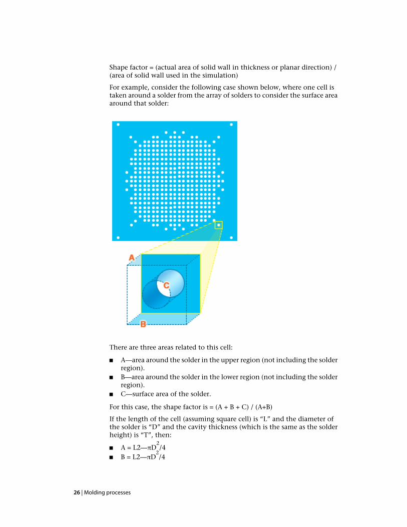
Shape factor = (actual area of solid wall in thickness or planar direction) /(area of solid wall used in the simulation)
For example, consider the following case shown below, where one cell istaken around a solder from the array of solders to consider the surface areaaround that solder:
There are three areas related to this cell:
■ A—area around the solder in the upper region (not including the solderregion).
■ B—area around the solder in the lower region (not including the solderregion).
■ C—surface area of the solder.
For this case, the shape factor is = (A + B + C) / (A+B)
If the length of the cell (assuming square cell) is “L” and the diameter ofthe solder is “D” and the cavity thickness (which is the same as the solderheight) is “T”, then:
■ A = L2—πD2/4
■ B = L2—πD2/4
26 | Molding processes

■ C = πDT
Multiple-barrel Reactive Molding analysis types andanalysis technologies
The following table shows the available analysis technologies for aMultiple-barrel Reactive Molding analysis type.
Table 12: Multiple-barrel Reactive Molding process and analysis types
Analysis TechnologyAnalysis Type
Fill+Pack
Molding processes | 27