mohammad faisal haider - bangladesh university of ...teacher.buet.ac.bd/fhaider/me267_steam...
TRANSCRIPT

Mohammad Faisal HaiderLecturerLecturer
Department of Mechanical EngineeringBangladesh University of Engineering and Technology

Steam Turbine
2

Vapor Power CycleVapor Power Cycle

4

5
Steam TurbineA steam turbine is prime mover which uses steam as its working fluidIt operates by performing two functions :
a part or whole of the pressure energy of steam is transformed into kinetic energy by means of expansion transformed into kinetic energy by means of expansion through suitable passages such as nozzles the kinetic energy and the remaining portion of the gy g ppressure energy of steam, if any, are converted into mechanical work with the help of moving blades fitted on the wheelon the wheel
6

Steam Turbine…Steam turbines are steady flow devices where steam enters thru nozzles, expands to lower pressure and in doing so develops high velocity i.e. high kinetic energy. Part of this kinetic energy of the jet can be used in the
j i d i h l Thi same manner as water jet is used in water wheel. This kind of turbine is called impulse turbine.
7

Turbine DetailMain componentsMain components
NozzlesBlades or bucketsWheel or rotorCasing or cylinderDiaphragmsGlands
The blades, also called moving blades are fitted over the circumference of the wheel which is again mounted over a shaft. The wheel is covered with a casing The nozzles and fixed blades are casing. The nozzles and fixed blades are fitted with casing
8

NozzleA nozzle is a steady flow device and is nothing but apassage of varying cross section for the flow of steami d t i it l it b i ithin order to increase its velocity by expansion withdegrease of pressure.Its main function is to convert the available enthalpyIts main function is to convert the available enthalpyinto kinetic energy by producing a jet of steam at ahigh velocity.g yThe section of a nozzle may be round, square, orrectangular. They are used in impulse turbines andfitted with the casing or with diaphragms.
9

Nozzle…In designing an ideal nozzle for constant entropy expansion, the cross‐sectional area at any point n may be computed by use of continuity equation
An = m vn /VnWhen the flow is adiabatic and frictionless, the entropy of the steam of any point in the nozzle is equal the initial
I i h h h h h entropy. It is necessary to choose the throat area so that the desired amount of steam may flow with the desired pressure drop.At th b i i f th fl i th l th t At the beginning of the flow in the nozzle, the steam velocity increase is rapid, although the corresponding volume increases at a lesser rate.
m is const and V/v m /Am is const and V/v=m /A
10

Nozzle…It is apparent that A must decrease until the flow has reached that section where the rate of increase in volume is equal to the rate of increase of in velocity. volume is equal to the rate of increase of in velocity. Here V/v is maximum and A is minimum.In divergent section, divergence angle is approximately 6 d f h li6 degrees from the centerline.The length of the nozzle is not critical and may be proportional on the basis of throat area by the relationproportional on the basis of throat area by the relationLength of the nozzle from throat to exit, L = √(15 A0)Efficiency does no depend on the shape of the cross section
11

Nozzle…
Specific volume, υ
V, A
υ,
Nozzle LengthInlet Exit
12
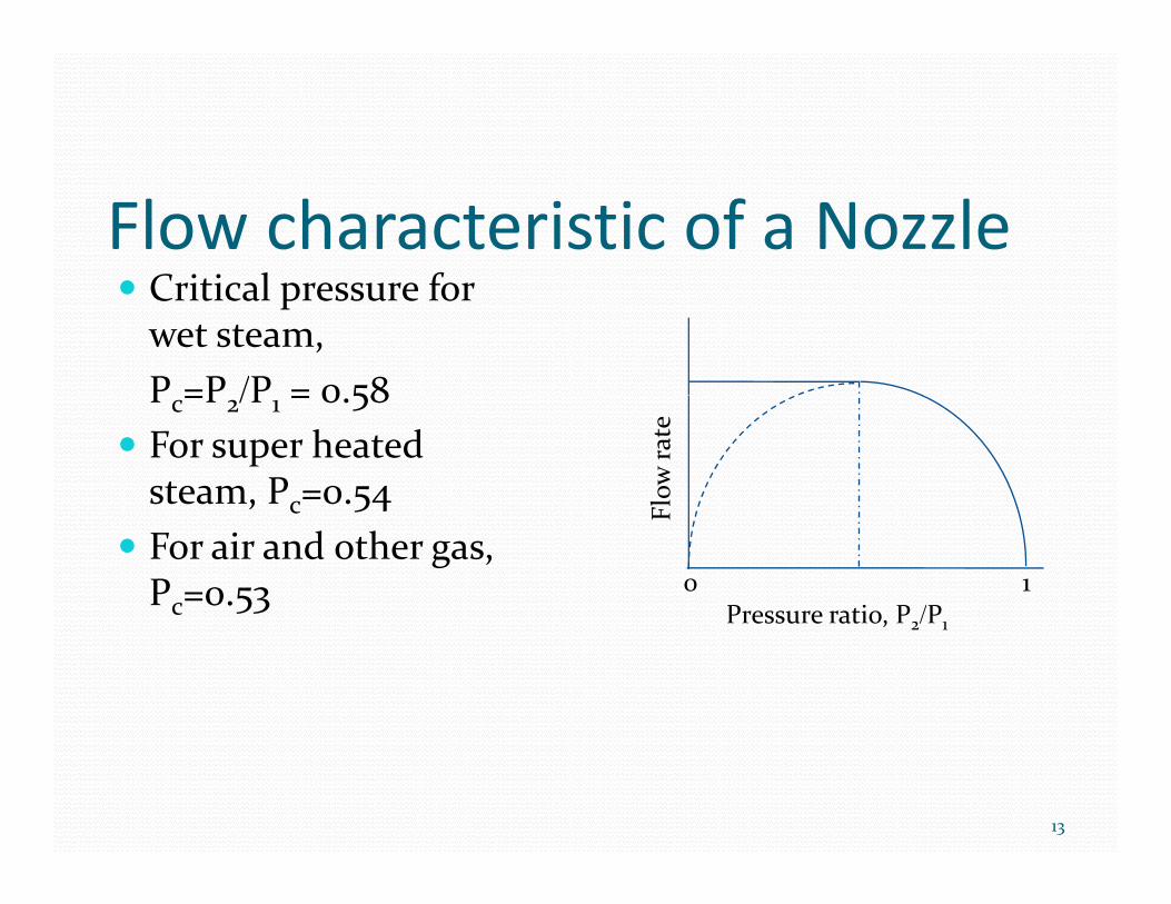
Flow characteristic of a NozzleC iti l f Critical pressure for wet steam, P =P /P = 0 58Pc=P2/P1 = 0.58For super heated steam, Pc=0.54 Fl
ow ra
te
, c 54For air and other gas, Pc=0.53 Pressure ratio, P2/P1
F
0 1essu e at o, 2/ 1
13

BladesTurbine blades also called buckets may be classified according to its shape as impulse blades and reaction blades.
The blades of both the groups may be of moving type or of stationary type. Moving blades are fixed on the rim of the wheel or rotor and stationary or guide or fi d bl d fi d i h h ifixed blades ate fitted with the casing.
14
Wheel and DiaphragmsA turbine wheel in its simplest form is like a flat discmounted on a shaft. It is also called the disc. Movingblades are fitted over the rim of the wheel in the formblades are fitted over the rim of the wheel in the formof a ring. The rotor consists of several discs.
Th di h i i h f f di hi h i fi dThe diaphragm is in the form of a disc which is fittedinside the cylinder. It serves the purpose of separatingwalls between the different stages of the turbine andwalls between the different stages of the turbine andcarries nozzles and fixed blades. It must be strongenough to withstand the high temperature and thepressure difference of working fluid.
15

GlandsGlands are required to prevent
(a) the leakage of working fluid from the cylinder to theoutside if its pressure is above the atmosphereoutside if its pressure is above the atmosphere,
(b) the leakage of air from outside to the cylinder if theinside pressure is less than the atmosphere,
(c) the leakage of working fluid from one stage to theother.
Glands are fitted in the place where the shaft entersinto the cylinder and the passage between the rotorand the diaphragmsand the diaphragms.
16

ClassificationDepending on the types of blades and methods of energy transfer from fluid to rotor wheel, turbines may be of two types: be of two types: Impulse TurbineReaction TurbineReaction Turbine
17

Impulse and Reaction PrinciplesImpulse and Reaction Principles
18

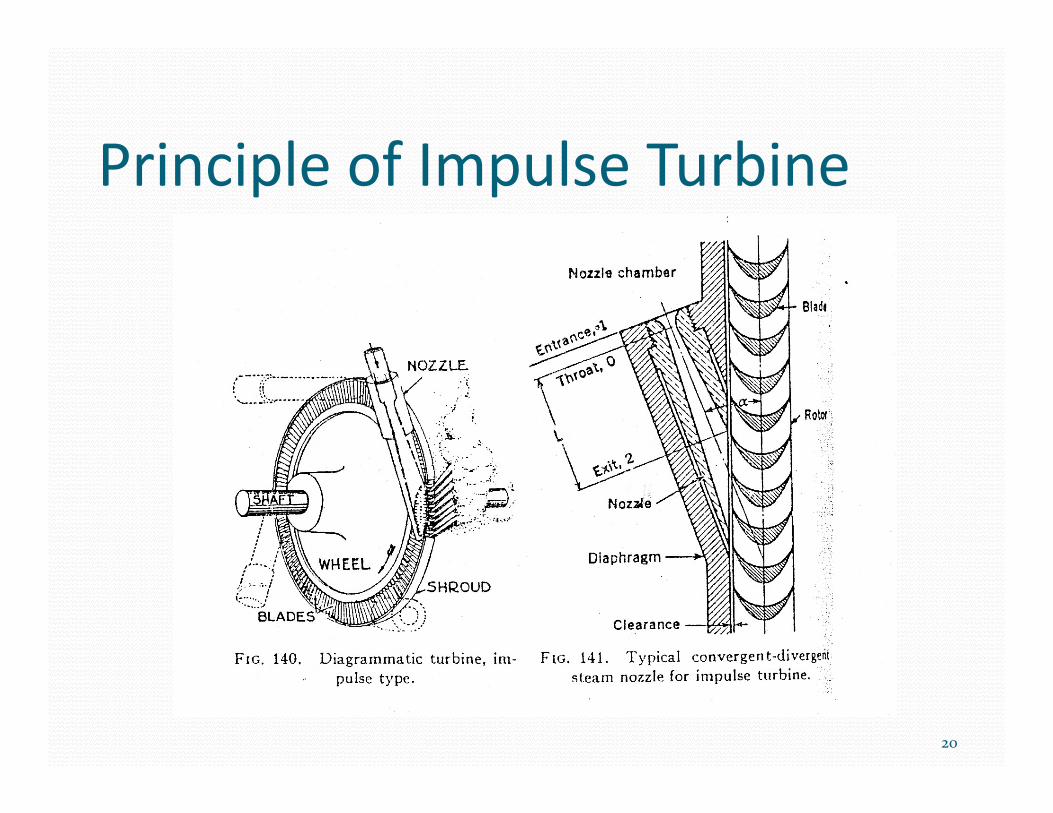
Impulse TurbineIn an impulse turbine the steamIn an impulse turbine, the steamtaken from the boiler firstcomes to the steam chest andthen it passes through nozzlesthen it passes through nozzlesand impacts on the movingblades.
D t th i l f tDue to the impulse of steamover the moving blades, thewheel rotates and so the poweris available from the shaftis available from the shaft.
As the steam expands throughthe nozzle, the velocity and thevolume of steam are increasedwith decrease in pressure
19
P i i l f I l T biPrinciple of Impulse Turbine
20

Impulse Turbine
21

Impulse TurbineIf all the pressure is dropped in one stage, the rotor speed is very large 10,000 to 30,000. If ideal condition can be provided, i.e. all kinetic energy can be converted to the rotor, then speed may be 20,000 to
40,000 rpm.
Such high speed is required to be reduced by gearing f d i S h i i d of under proportion. So more than one staging is done
in impulse turbine namely either pressure staging (Rateau staging) or velocity staging (Curtis staging)(Rateau staging) or velocity staging (Curtis staging).
22

Pressure StagingPressure Staging (Rateau)
I th l l • In the nozzles, only a small pressure drop is provided giving limited provided giving limited increase of kinetic energy
• Rotating rows of blades and fixed rows of blades are being keyed to the h f i ishaft in series
23

Pressure Staging (Rateau)The rotating blades have the typical symmetrical shape of impulse turbine. The fixed blades will not only change the direction of steam but will increase only change the direction of steam, but will increase the speed also. So, they are in fact nozzles. Since pressure gradually goes down volume will Since pressure gradually goes down, volume will increase and therefore the blade height has to be increased towards the low pressure side.
24

Velocity StagingVelocity Staging (Curtis)
Lik i l t i l • Like a single stage impulse turbine, velocity compounding allows a larger pressure drop in one set of nozzles.A di t th l it • According to the velocity with which the steam issues from the nozzle, two or more rings of moving blades separated by rings of fixed blades are keyed in series on
25
blades are keyed in series on the common shaft.

Velocity Staging (Curtis)A fall in velocity occurs every time when the steam passes over rings of moving blades.Si h f bl d d h Since the rows of blades are connected to the same shaft, there is no loss of power.
26
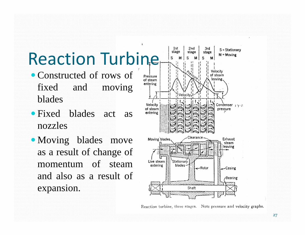
Reaction TurbineC t t d f fConstructed of rows offixed and movingbladesFixed blades act asnozzlesMoving blades moveas a result of change of
t f tmomentum of steamand also as a result ofexpansion.p
27

Reaction TurbineIn the reaction turbine, the rotor blades themselves are arranged to form convergent nozzles. This type of turbine makes use of the reaction force produced as the steam accelerates through the nozzles formed by the rotor. Steam is directed onto the rotor by the fixed vanes of the stator. It leaves the stator as a jet that fills the entire circumference of the rotor. jThe steam then changes direction and increases its speed relative to the speed of the blades. A pressure drop occurs across both the stator and the rotor, with steam accelerating through the stator and decelerating through the rotor, with no net change in steam velocity across the stage but with a decrease in both pressure and temperature, reflecting the work performed in the driving of the rotor.
28

Typical Rankine Cycle
29
T‐s diagram of a typical Rankine cycle operating between pressures of 0.06bar and 50bar

Typical Rankine CycleThere are four processes in the Rankine cycle, these states are identified by number in the diagram to the right.P Th ki fl id i d f l t hi h Process 1‐2: The working fluid is pumped from low to high pressure, as the fluid is a liquid at this stage the pump requires little input energy.q p gyProcess 2‐3: The high pressure liquid enters a boiler where it is heated at constant pressure by an external heat source b d d Th i i d to become a dry saturated vapor. The input energy required
can be easily calculated using mollier diagram or h‐s chart or enthalpy‐entropy chartpy py
30

Typical Rankine CycleProcess 3‐4: The dry saturated vapor expands through a turbine, generating power. This decreases the temperature and pressure of the vapor, and some condensation may occur. The output in this process
b il l l d i h E h l can be easily calculated using the Enthalpy‐entropy chart
P Th h Process 4‐1: The wet vapor then enters a condenser where it is condensed at a constant pressure to become a saturated liquidpressure to become a saturated liquid.
31

Rankine Cycle with Superheata e Cyc e t Supe eat
The compression by the pump and the expansion in the turbine are not isentropic.
This somewhat increases the power d b h d d h required by the pump and decreases the
power generated by the turbine.In particular the efficiency of the
steam turbine will be limited by water steam turbine will be limited by water droplet formation. As the water condenses, water droplets hit the turbine blades at high speed causing pitting and g p g p gerosion, gradually decreasing the life of turbine blades and efficiency of the turbine.
32
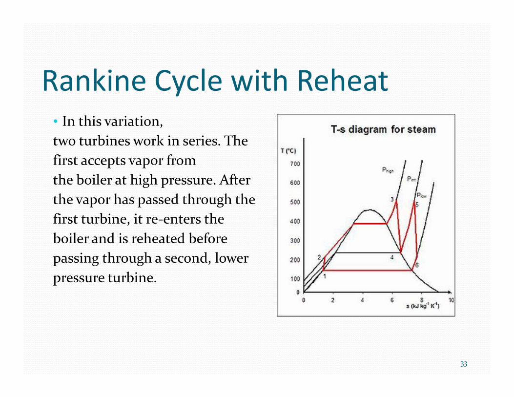
R ki C l ith R h tRankine Cycle with Reheat• In this variation In this variation, two turbines work in series. The first accepts vapor from the boiler at high pressure. After the vapor has passed through the first turbine, it re‐enters the st tu b e, t e e te s t eboiler and is reheated before passing through a second, lower
bi pressure turbine.
33

R ki C l ith R tiRankine Cycle with Regeneration• In regenerative Rankine cycle In regenerative Rankine cycle, after emerging from the condenser the working fluid is heated by steam tapped from the hot portion of the cycle.
• On the diagram shown, the O t e d ag a s o , t efluid at 2 is mixed with the fluid at 4 (both at the same pressure) d i h h d to end up with the saturated
liquid at 7. This is called "direct contact heating".
34
g

Rankine Cycle with Regeneration• The Regenerative Rankine cycle (with minor variants) is commonly
used in real power stations.Another variation is where 'bleed steam' from between turbine stages is gsent to feedwater heaters to preheat the water on its way from the condenser to the boiler. These heaters do not mix the input steam and condensate, function as an ordinary tubular heat exchanger, and are y gnamed "closed feedwater heaters".The regenerative features here effectively raise the nominal cycle heat input temperature, by reducing the addition of heat from the p p , y gboiler/fuel source at the relatively low feedwater temperatures that would exist without regenerative feedwater heating. This improves the efficiency of the cycle, as more of the heat flow into the cycle occurs at y y yhigher temperature.
35