moffett field, california reynolds and mach numbers · pdf filemoffett field, california ....
TRANSCRIPT
.. , NATIONAL ADVISORY COMMITTEE FOR AERONAUTICS
AMES AERONAUTICAL LABORATORY MOFFETT FIELD, CALIFORNIA
REYNOLDS AND MACH NUMBERS
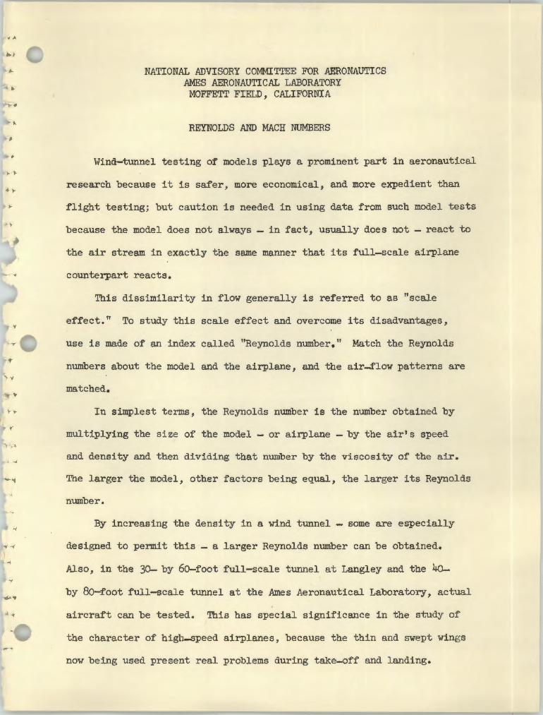
Wind-tunnel testing of models plays a prominent part in aeronautical
research because it is safer, more economical, and more expedient than
.. flight testing; but caution is needed in using data from such model tests
because the model does not always - in fact, usually does not - react to
the air stream in exactly the same manner that its full-scale airplane
counterpart reacts.
This dissimilarity in flow generally is referred to as "scale
effect." To study this scale effect and overcome its disadvantages,
use is made of an index called "Reynolds number." Match the Reynolds
numbers about the model and the airplane, and the air-flow patterns are
matched. "
In simplest terms, the Reynolds number is the number obtained by
multiplying the size of the model - or airplane - by the air's speed .. and density and then dividing that number by the viscosity of the air.
The larger the model, other factors being equal, the larger its Reynolds
number.
By increasing the density in a wind tunnel - some are especially
-( designed to permit this - a larger Reynolds number can be obtained.
Also, in the 30- by 60-foot full-scale tunnel at Langley and the 4o
by 80-foot full-scale tunnel at the .Ames Aeronautical Laboratory, actual
aircraft can be tested. This has special significance in the study of
the character of high-speed airplanes, because the thin and swept wings
now being used present real problems during take-off and landing.
• •
., .
.. . -2
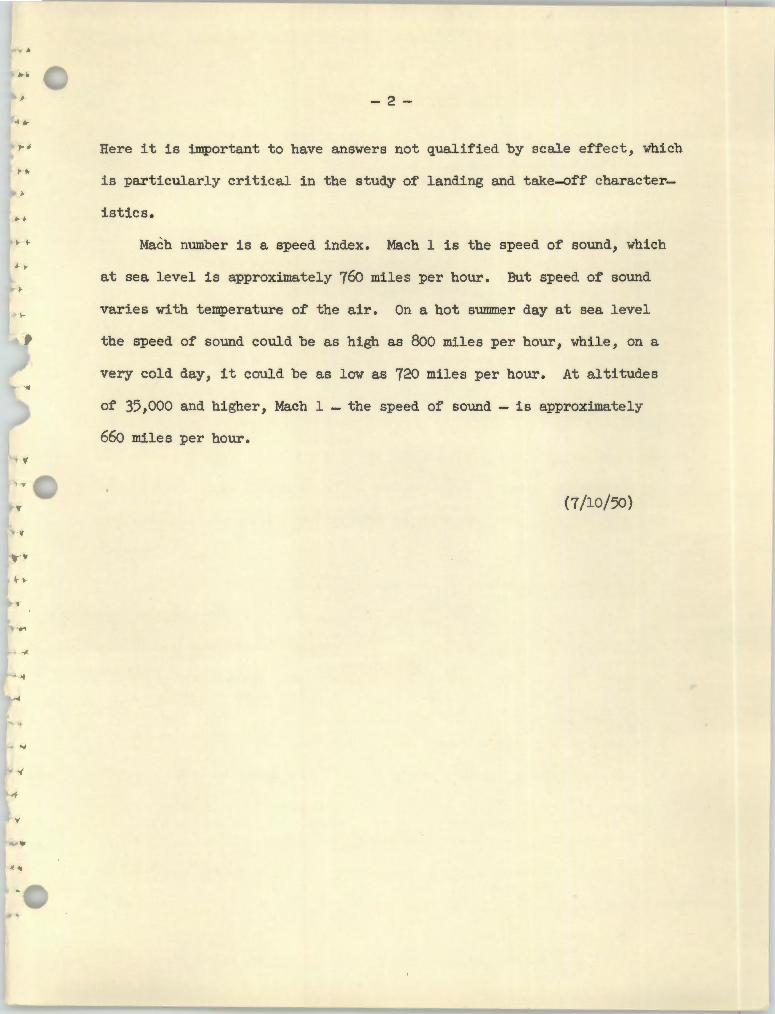
Here it is important to have answers not qualified by scale effect, which
is particularly critical in the study of landing and take-aft' character
istics•... • • Mach number is a speed index. Mach 1 is the speed of sound, which
at sea level is approximately 76o miles per hour. But speed of sound
varies with temperature of the air. On a hot summer day at sea level
the speed of sound could be as high as 800 miles per hour, while, on a
very cold day, it could be as low as 720 miles per hour. At altitudes
of 35,000 and higher, Mach 1 - the speed of sound - is approximately
660 miles per hour. , I(
(7/10/50)

••
~
.. A
NATIONAL ADVISORY COMMITTEE FOR AERONAUTICS AMES AERONAUTICAL LABORATORY.
~ .. MOFFETT FIELD, CAL .
....
.. "' For Release:
->
•• Saturday, July 8, 1950
,._ . .. ~ AMES LABORATORY HOLDS 1950 INSPECTION NEXT WEEK; MA.NY
DISTINGUISHED GUESTS TO VISIT RESEARCH CENTER>
Latest developments in the aerodynamic fields of avj_ation research
will be reviewed for more than 800 distinguished visitors next week
when the Ames Aeronautical Laboratory of the National Advisory Committee
for Aeronautics holds its 1950 Inspection at Moffett Field .
On Monday, Tuesday, and Wednesday, July 10, 11, and 12, the NACA
and the Laboratory staff, headed by Director Smith J. DeFre.nce, will
be hosts to high ranking officers of the Air Force, Navy, Army and
Marines, Government officials, aviation industries representatives,
aeronautical scientists and San Francisco Bay Region civic leaders
Touring the Laboratory's various wind tunnels and other installa
tions used in the study of the many phases of aerodynamics, the
visitors will hear discussions of the problems which have arisen in
this research field - - particularly in the transonic and supersonic
speed ranges - - and of the progress which has been made toward solu-·
tion of the problems. These reports will cover not only work done at
Ames during the past two years, but also research results from the
... NACA Langley Aeronautical Laboratory in Virginia •
Ames research scientists, engineers and technicians will demon
strate the Laboratory's newest equipment and will explain theoretical

.. .... .. .... ..
-2
and experimental techniques which have been developed to facilitate
scientific exploration of new frontiers opened up by the advent of
flight faster than the speed of sound. , .
Most of the visitors on the opening day of the inspection will be ' '
civilians, including representatives of the administrative design nnd
operating branches of the aircraft manufacturing and air transport • f
industries, members of Congress, officials of Government agencies
concerned with aviation, and scientists from other research agencies
and from educational institutions. On Tuesday, the majority of the
guests will be officers of the armed forces.
The final day of the inspection has been set aside for future
leaders of the flying services. One group, comprising 140 faculty
members and officer-students, will come by air from the Air Force ' 1
Institute of Technology at Wright Field, Ohio. Students from other
.' armed forces air training centers and schools will also attend .
...
- '
+•

NATIONAL ADVISORY COMMITI'EE FOR AERONAUTICS AMES AERONAUTICAL LABORATORY
MOFFETT FIELD, CALIF •
..; . For Release... PM's, MONDAY July 10, 1950
f
AIRCRAFT MODELS FIRED FROM GUNS IN NEW SUPERSONIC WIND TUNNEL AT NACA AMES LABORATORY
- ~
A new and unusual type of wind tunnel in which models are fired
from guns was demonstrated today at the Ames Aeronautical L~boratory
of the National Advisory Committee for Aeronautics. The tunnel
already has provided aerodynamic data at eight times the speed of
sound, or about 6,000 miles per hour at sea level.
Visitors attending the 1950 inspection at Ames Laboratory at
Moffett Field were told that this new research facility, known as ' 1
\ . the supersonic free-flight wind tunnel, will eventually be capable ' .
of operating up to 15 times sonic speed, equivalent to 11,000 mph
at sea level. In fact, additional equipment is being procured which
.. will permit future research at such velocities.
The supersonic free-flight tunnel is currently being used to
study the characteristics of missile-type configurations at high
supersonic (hypersonic) speeds.
An outstanding feature of the new tunnel is the fact that while
the models are only a few inches in length, very high test Reynolds
numbers are obtainable, making the research results comparable to
those for far larger models. Due to the relatively high density of
the air in this wind tunnel, a six-inch model tested at a Mach number
-2
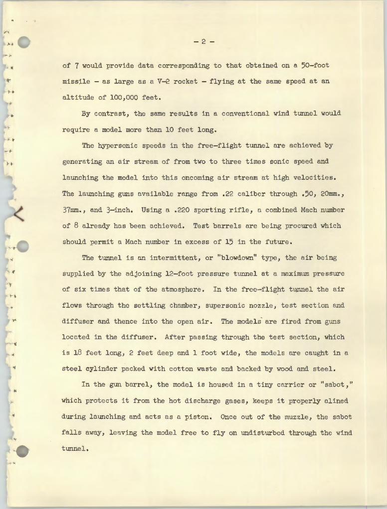
of 7 would provide data corresponding to that obtained on a 50-foot• missile - as large as a V-f:. rocket - flying at the same speed at an
altitude of 100,000 feet.
By contrast, the same results in a conventional wind tunnel would• require a model more than 10 feet long.
The hypersonic speeds in the free-flight tunnel are achieved by _...
generating an air stream of from two to three times sonic speed and
launching the model into this oncoming air stream at high velocit1.es.
The launching guns available range from .22 caliber through .50, 20mm.,
37mm., and 3-inch. Using a .220 sporting rifle, a combined Mach number
of 8 already has been achieved. Test barrels are being procured which
should permit a Mnch number in excess of 15 in the future.
The tunnel is an intermittent, or "blowdown" type, the air being
supplied by the adjoining 12-foot pressure tunnel at a maximum pressure
of six times that of the atmosphere. In the free-flight tunnel the air
flows through the settling chamber, supersonic nozzle , test section and
diffuser and thence into the open air. The models are fired from guns
located in the diffuser. After passing through the test section, which
is 18 feet long, 2 feet deep nnd 1 foot wide, the models are caught in a
steel cylinder packed with cotton waste and backed by wood and steel.
In the gun barrel, the model is housed inn tiny carrier or "sabot," .. which protects it from the hot discharge gases, keeps it properly alined
during launching and acts as a piston. Once out of the muzzle, the sabot
falls away, leaving the model free to fly on undisturbed through the wind
tunnel.
--<"<
- 3
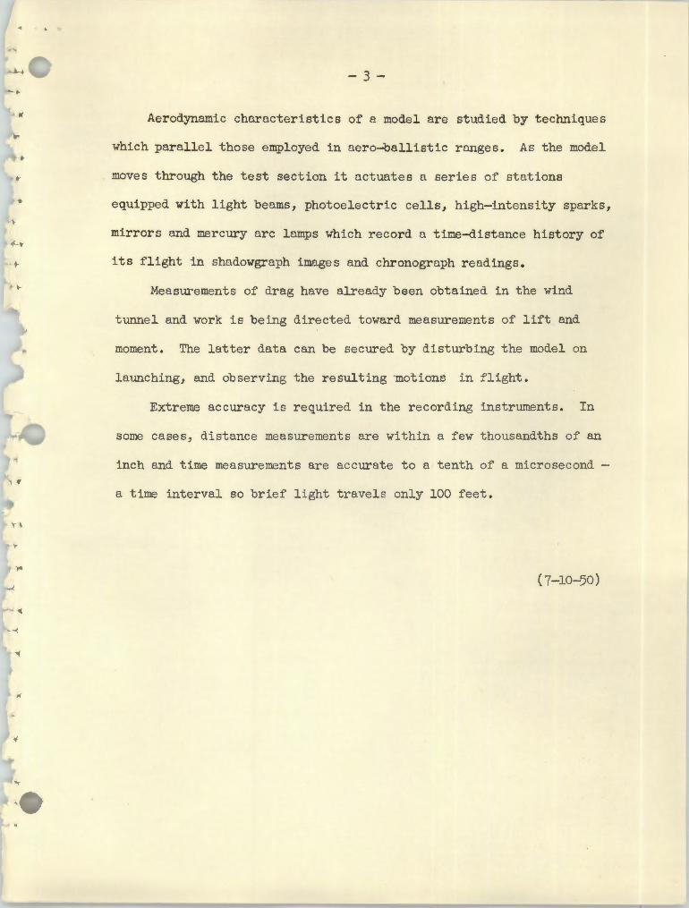
Aerodynamic chnracteristics of a model are studied by techniques
which parallel those employed in aero~allistic rnnges. As the model
moves through the test section it actuates a series of stations
• equipped with light beams, photoelectric cells, high-intensity sparks,
mirrors and mercury arc lamps which record a time-distance history of
its flight in shadowgraph images and chronograph readings.
Measurements of drag have already been obtained in the wind
tunnel and work is being directed toward measurements of lift and
moment. The latter data can be secured by disturbing the model on•
launching, and observing the resulting motions in flight.
Extreme accuracy is required in the recording instruments. In
some cases, distance measurements are within a few thousandths of an
inch and time measurements are accurate to a tenth of a microsecond -
a time interval so brief light travels only 100 feet.
,. ( 7-10-50)
..
CD L
aunc
hing
gu
n
~
@ M
odel
in
flig
ht
@ T
ime-
dist
ance
re
cord
ing
stat
ions
@ S
uper
soni
c no
zzle
@ M
odel
cat
cher
@ D
irect
ion
of
air
stre
am
~
A-1
50
58
.1
NA
llON
AL
AD
VIS
OR
Y C
OM
MIT
TEE
FOR
AER
ON
AU
TIC
S
AM
ES A
ERO
NA
UllC
AL
LABO
RATO
RY,
MO
FFET
T FI
ELD
, CA
LIF.

\ ...
""')
NA
TIO
NA
L A
DV
ISO
RY
CO
MM
ITTE
E FO
R A
ERO
NA
UTI
CS
AM
Eq
AER
ON
AU
TIC
AL
LABO
RATO
RY
MO
FFET
!' F
IEI.
D,
CA
LIFO
RN
IA
A-1
50
58
.l
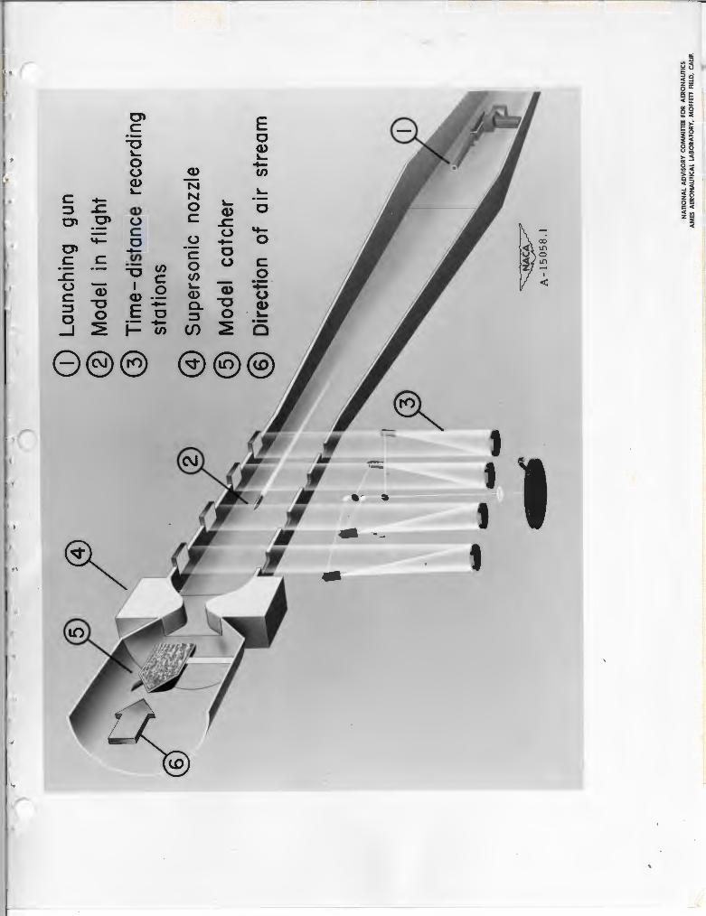
Cut
away
dra
win
g ex
pla
inin
g-t
he
maj
or
oper
a.ti
ng f
eatu
res
of
the
new
su
pers
on
ic f
ree-f
lig
ht
win
d -
tun
nel
at
the
Am
es
Aer
on
auti
cal.
.L
abo
rato
ry .
crf
the N
ACA
. F
ired
fro
m g
uns
at
one
end
of
the
win
d tunnel~
mod
els
·fly
th
rou
gh
an
air
str
eam
sp
eed
ing
in
the
op
po
site
dir
ecti
on
. V
ery
hig
h t
est
!peed
s re
sult
, re
ach
ing
velo
cit
ies
equ
ival
ent
to m
ore
than
6,o
oo m
ph at
sea
lev
el
in
the te
st ~
ection.,

... '\
'
NA
TIO
NA
L A
DV
ISO
RY
CO
MM
ITTE
E F
OR
AE
RO
NA
UTI
CS
A
ME
S A
ER
ON
AU
TIC
AL
LAB
OR
ATO
RY
, M
OFF
ETT
FIEL
D, C
ALI
F.

NATI
ONAL
ADV
ISOR
Y CO
MM
ITTE
E FO
R AE
RONA
UTIC
S
AMES
AER
ONAU
TICA
L LA
BORA
TORY
MOF
FETT
FIE
LD,
CALI
FORN
IA
A-1
5057
Mod
els
lau
nch
ed f
rom
gun
s in
th
e ne
w
sup
erso
nic
fre
e
flig
ht
win
d tu
nn
el a
t th
e A
mes
A
ero
nau
tica
l L
abo
rato
ry o
f th
e
NACA
are
pro
tect
ed i
n t
he
gun
barr
el
by
pla
stic
"sa
bo
ts"
whi
ch
keep
th
e m
odel
s
co
rrectl
y a
lig
ned
and
act
as p
isto
ns
on f
irin
g.
Th
is d
raw
ing
show
s w
hat
happ
ens
whe
n th
e m
odel
lea
ves
th
e g
un
muz
zle.
N
ote
how
th
e sa
bo
t se
par
ates
and
fall
s aw
ay,
leav
ing
th
e
mod
el f
ree to
co
nti
nu
e it
s f
lig
ht
thro
ug
h t
he
test
secti
on
, w
here
mea
sure
men
ts
are
mad
e.
\\..
"i
\ ...

NATIONAL .ADVISORY COMMITTEE FOR AERONAUTICS AMES AERONAUTICAL LABORATORY
MOFFETT FIELD, CALIF.
For Release:
AM's, TUESDAY July 11, 1950
2000 - 5000 MPH SPEED RANGE COVERED IN NEWEST WIND TUNNEL Kr AMES LABORATORY
Capable of supplying aerodynamic data over the wide range of 2.75
to more than 7 times the speed of sound, a new research tool known
as the 10- by 14--inch supersonic wind tunnel is now in operation at the
Ames Aeronautical Laboratory of the National Advisory Committee for
Aeronautics. The new wind tunnel's range is roughly equivalent to sea
level airspeeds of 2000 to 5000 miles per hour.
The 10- by 14--inch wind tunnel (so designated because that is the
size of its test section) was developed for use in the intensified study
of air-flow problems encountered at high supersonic (hypersonic) speeds,
and incorporates the latest developments in nozzle design and instru
menta~ion. Its operation was explained yesterday at the opening day of
the Laboratory's 1950 Inspection at Moffett Field.
Inspection visitors were told that recent spectacular advances in
actual and potential flight speeds have made necessary the creation of
new research apparatus which will supply basic information needed for
the design of future missiles and aircraft. Much of this needed data
involves air-flow changes occurring around a body traveling from transonic
and low supersonic to hypersonic speeds (Mach number 5 and upwards).
Development of such special equipment has been in progress at the Ames,
---,..~~-----==========~=======================~=====--1
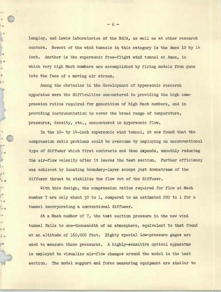
- 2
Langley, and Lewis Laboratories of the NACA, as well as at other research
centers. Newest of the wind tunnels in this category is the Ames 10 by 14
inch. Another is the supersonic free-flight wind tunnel at Ames, in
which very high Mach numbers are accomplished by firing models from guns
into the face of a moving air stream.
A~ong the obstacles in the development of hypersonic research
apparatus were the difficulties encountered in providing the high com
pression ratios required for generation of high Mach numbers, and in
providing instrumentation to cover the broad range of temperature,
pressures, density, etc., encountered in hypersonic flow.
In the 10- by 14-inch supersonic wind tunnel, it was fotmd that the
compression ratio problems could be overcome by employing an unconventional
type of diffuser which first contracts and then eJCpands, smoothly reducing
the air-flow velocity after it leaves the test section. Further efficiency
was achieved by locating boundary-layer scoops just downstream of the
diffuser throat to stabilize the flow out of the diffuser.
With this design, the compression ratios required for flow at Mach
number 7 are only about 30 to 1, compared to an estimated 200 to 1 for a
tunnel incorporating a conventional diffuser.
At a Mach number of 7, the test section pressure in the new wind
tunnel falls to one-thousandth of an atmosphere, equivalent to that found
at an altitude of 160,000 feet. Eighty special low-pressure gages are
used to measure these pressures. A highly-sensitive optical apparatus
is employed to visualize air-flow changes around the model in the test
section. The model support and force measuring equipment are similar to

;. I
-3
those in other supersonic wind tunnels. The models are supported from
the rear on a "sting," which in turn is supported by a strut passing
through the sidewalls. The forces and moments acting on the model are
measured by a conventional strain-gage balance system.
(7/10/50)
..
•


NATIONAL ADVISORY COMMITTEE FOR AERONAUTICS
AMES AERONAUTICAL IABORATORY
MOFFETT FIEIJ), CALIFORNIA
A-14617
The upper and lower nozzle blocks of the new 10-by 14-inch
supersonic wind tunnel at the Ames Aeronautical Laboratory of the
NACA. One s~.de plate has been removed to show (from left to
right) the supersonic nozzle, the test section where models are
mounted, and the converging and diverging passages of the diffuser,
as well as the boundary-layer scoops which help stabilize the flow
of air out of the diffuser. The jacks are used to change the
shape of the nozzle and diffuser openings. The air flow is from
left to right.
..
'
NATIONAL ADVISORY COMMITTEE FOR AERONAUTICS AMES AERONAUTICAL LABORATORY
MOFFETT FIELD, CALIF.
For Release on Receipt
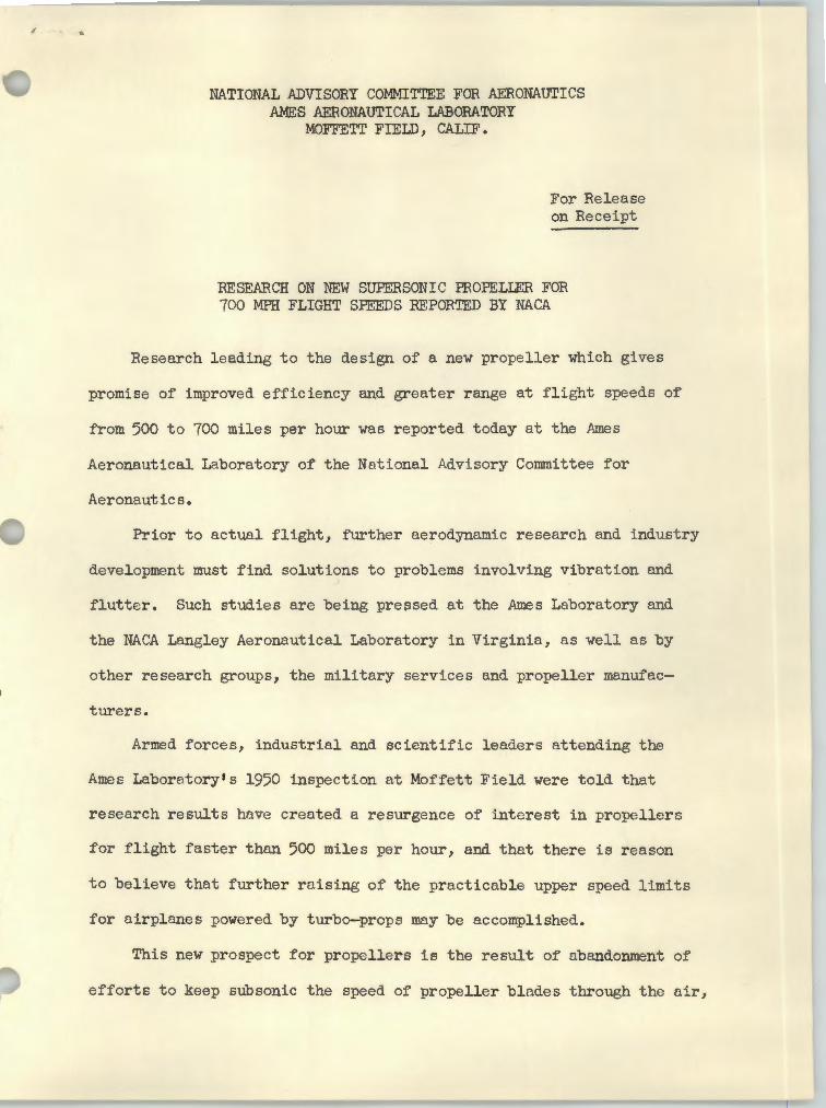
RESEARCH ON NEW SUPERSONIC PROPELLER FOR 700 MPH FLIGHT SPEEDS REPORTED BY NACA
Research leading to the design of a new propeller which gives
promise of improved efficiency and greater range at flight speeds of
from 500 to 700 miles per hour was reported today at the A.mes
Aeronautical Laboratory of the National Advisory Committee for
Aeronautics.
Prior to actual flight, further aerodynamic research and industry
development must find solutions to problems involving vibration and
flutter. Such studies are being pressed at the Ames Laboratory and
the NACA Langley Aeronautical Laboratory in Virginia, as well as by
other research groups, the military services and propeller manufac. turers.
Armed forces, industrial and scientific leaders attending the
Ames Laboratory's 1950 inspection at Moffett Field were told that
research results have created a resurgence of interest in propellers
for flight faster than 500 miles per hour, and that there is reason
to believe that further raising of the practicable upper speed limits
for airplanes powered by turbo-props may be accomplished.
This new prospect for propellers is the result of abandonment of
efforts to keep subsonic the speed of propeller blades through the air,

•'"
..
-2
the Laboratory reported. As a result, the new propeller is termed
"supersonic," in that all parts may travel at speeds above the speed
• of sound (about 76o mph at sea level temperatures) even though the
airplane is flying at subsonic speed.
It was pointed out that as ea:r-ly as the 1920 1 s, loss of propeller
efficiency from compressibility effects at the blade tips was observed.
To reduce these losses, engines were geared to rotate the propellers
more slowly. This in turn required larger propellers, and the increased
diameter necessitated even greater reduction in the rotational speed of
the propeller.
In addition, blade angles became so large that too much power was
wasted pushing the air around with the propeller instead of propelling
the airplane forward by pushing back on the air. These limitations
were such that propellers could not compete with turbo-jet engines at
flight speeds much above eight-tenths of the speed of sound •
. The new supersonic design uses smaller blade angles and very thin
blade sections compared to the older type. Also, because of its higher
rotational speed, the supersonic propeller need have only half the
diameter of a subsonic propeller for the same power, and this permits
important savings in the weight of the propeller and drive gearing.
It also permits a shorter and lighter landing gear for the airplane .
On the other hand, the extreme thinness of the new propeller blades
has intensified the problems of vibration and flutter, which were limit
ing factors even with the thicker subsonic blades. But laboratory
research has shown that proper selection of blade width can help prevent
.
t-
l
..
..
••
- 3
flutter, and advances are reported in methods of calculating blade vibra
tion cycles. From such work, it is hoped to provide better tools for the
engineer's use in analyzing his propeller designs to avoid flutter and
vibration•
.
(7-10-50)
.
•
..
..