moe fy 2014 feasibility studies on joint crediting mechanism · fy 2014 feasibility studies on...
TRANSCRIPT
MOE
FY 2014 Feasibility Studies on Joint Crediting Mechanism
Projects towards Environmentally Sustainable Cities in Asia
“Study for the development of JCM projects for comprehensive
improvements in the power generation, transmission and distribution
systems in Ulaanbaatar City and on the possibility of nationwide
horizontal application of the same improvement model in Mongolia”
Final Report
March 2015
Overseas Environmental Cooperation Center, Japan

FY 2014 Feasibility Studies on Joint Crediting Mechanism Projects towards
Environmentally Sustainable Cities in Asia
Study for the development of JCM projects for comprehensive improvements in the
power generation, transmission and distribution systems in Ulaanbaatar City and
on the possibility of nationwide horizontal application of the same improvement
model in Mongolia
Final Report
Contents
I. SUMMARY ................................................................................................. 1
1. Background ............................................................................................... 1
2. Scope ......................................................................................................... 1
3. Methodology .............................................................................................. 2
4. Results ...................................................................................................... 3
5. Review for Commercialization ................................................................. 3
II. REPORT ...................................................................................................... 5
1. Background ............................................................................................... 5
2. Scope .......................................................................................................... 9
(1) Power Generation, Transmission and Distribution Measures ........... 9
(2) Advanced Nature of Japanese Technologies in Power Generation,
Transmission and Distribution and the Feasibility of Sharing These
at Other Locations ................................................................................ 9
3. Study Item ............................................................................................... 10
(1) Implementation Structure ................................................................. 12
(2) Details of Study .................................................................................. 12
4. Study Results........................................................................................... 14
(1) Performance and Results ................................................................... 14
(2) Reduction of GHG Emissions ............................................................ 15
(3) Total Project Cost ............................................................................... 15
(4) Co-benefit effects ................................................................................ 16
(5) Identifying Needs of Power Generation, Transmission and
Distribution for Implementation at Other Cities or Facilities and
Support for Project Structuring ......................................................... 17
5. Review for Commercialization ................................................................ 21
(1) Commercialization/JCM Scenarios ................................................... 21
(2) MRV Methodology and Monitoring System ...................................... 23

(3) Implementation Plan and Detailed Schedule ................................... 54
Abbreviation List ......................................................................................... 55
- 1 -
I. SUMMARY
1. Background
Currently, power demand condition has become serious in Mongolian Central
Energy Grid, supplies power to Ulaanbaatar, the capital of Mongolia. Each year
Mongolia’s power supply shortage grows up, which has made increasing the
power supply and improving the efficiency of existing power stations urgent
tasks. However, air pollution and growth of GHG are having a toll on the
environment, requiring measures to be implemented soon.
Coal-fired combined heat and power plants (hereinafter “CHP”) are considered
to be very important facilities for implementing effective environmental
measures. CHP matches the needs of Mongolia and has the potential of
large-scale efficiency improvement by using Japanese technologies. Mongolian
Government requires the introduction of Japanese high efficiency equipment of
power transmission and distribution sectors as well. In addition, it was found
that Mongolia’s power generation, transmission and distribution facilities are
adopted by the technologies, standards and specifications from the former Soviet
Union technologies. It has been appeared that the solution can be easily
distributed to the other cities inside and outside Mongolia in a similar
technological situation.
Given this background, we stated a detailed study on Ulaanbaatar’s power
generation, transmission and distribution systems with the goal of introducing
leading technologies from Japan using Joint Credit Mechanism (hereinafter
“JCM”). Also, a study into project structuring was carried out with an eye on
rolling out possible solutions for the power grids of other cities.
2. Scope
The following study was focused on Ulaanbaatar Thermal Power Plant No. 3
(hereinafter “CHP-3”) as a project of efficiency improvement and GHG reduction.
The study is also related with the reduction of air pollution materials.
(1) Efficiency improvement of Ulaanbaatar Thermal Power Plant No. 3
(2) Fundamental capacity upgrading of the of power transmission and
distribution facilities in Ulaanbaatar

- 2 -
(3) Needs capture and project support of power generation, transmission and
distribution for implementation in other cities or facilities.
3. Methodology
As a practical JCM project for reducing GHG, we visited the project
counterparties on the first study, Ministry of Energy, Ministry of Environment,
Green Development and Tourism, CHP-3, and Ulaanbaatar Electricity
Distribution Network Company together with experts of power generation.
During these meetings, the business plan for this fiscal year was explained,
discussions were held on the details of the study, and requests were made for
obtaining necessary detailed information for moving the study forward. On
the second study, we asked the performance test in order to obtain the summer
operation data for calculating reference GHG and designing the low-carbon
technologies to be introduced. With the goal of technology distribution to
elsewhere in the country, we visited and held meetings at a mine and combined
heat and power generation facilities in Mongolia’s second largest city, Erdenet,
and third largest city, Darkhan, where officials were briefed on the bilateral
credit program and discussions were held on future approaches to the study.
Interviews were also conducted on the need for efficiency improvements.
Performance testing was carried out for the third and fourth parts of the study
in order to obtain operational data for the winter season. Discussions were held
with officials on obtaining detailed information requested from the Mongolia
side and, as well as obtaining specifications for facilities with advanced
technologies. Power plants in Mongolia use a combined cycle that supplies heat
(hot water). During the winter season in particular, hot water accounts for a
majority of demand, so reference data was collected on the use of heat by power
plants in order to define Business as Usual (BaU) emissions and reference
emissions. As the final component of the study, the fifth part involved
explaining the results of the study thus far to officials at CHP-3. Additionally,
the implementation system and project schedule were explained for projects
funded by the JCM Japan Fund set to commence next fiscal year.
A training program was held in Japan for the Mongolian side in order to
foster understanding in the technologies of specific companies. This allowed
officials to come into direct contact with targeted technologies, such as
optimized controls, heat pump systems, battery systems and operational

- 3 -
management of power plants, for which Japanese technologies take advantages.
This experience helped to aware the knowledge about these important
technologies.
4. Results
As a result of the six field studies and one training program held in Japan, we
collected the data on the Optimized Control System technologies to be
introduced in CHP-3. The data is BaU emissions and reference emissions. And
we summarized the qualification requirements for JCM and MRV methodology.
With regard to power transmission and distribution, we collected the data from
the Ulaanbaatar Electricity Distribution Network Company, and summarized
the qualification requirements for JCM and MRV methodology. Furthermore,
we identified new potential for upgrading/ increasing the capacity of boiler,
turbine and generator (BTG) and the introduction of storage cells/photovoltaic
power systems. In addition to Ulaanbaatar, combined cycle facilities in
Darkhan and Erdenet were visited with the aim of rolling out these same
technologies, which confirmed that there is strong demand for OCS and other
target technologies in other regions, building momentum for eventual
implementation.
During the fifth and sixth study, the results of the review thus far were
reported to officials from the Mongolian side, including those from the Ministry
of Energy, the Ministry of Environment, Green Development and Tourism,
CHP-3, and Ulaanbaatar Electricity Distribution Network Company. At the
same time, discussions were held on actions for the subsequent fiscal year
where officials were briefed on and agreed to the actions and schedule for next
fiscal year
5. Review for Commercialization
We suppose the target for energy supply sector and several billions of
yen in project costs at the least will be required for power generation,
transmission and distribution. The financing scheme for realizing this
project will be one that aims to enable leap-frog development.
On June 25, 2014, Minister of the Environment Nobuteru Ishihara
held talks with Takehiko Nakao, President of the Asian Development

- 4 -
Bank in Tokyo during his visit to Japan, where they signed a Letter of
Intent for Cooperation on Environmental Issues. They also announced
the establishment of a new trust fund (JCM Japan Fund) utilizing JCM
to support the adoption of advanced low-carbon technologies in its
developing member countries (DMCs), with a grant of ¥1.8 billion from
the Government of Japan.
This fund was established to mitigate additional costs with funds placed
in a trust managed by the Asian Development Bank to ensure that
advanced low-carbon technology projects are adopted, since the adoption
of these types of Asian Development Bank projects have not made much
progress because of the high implementation costs.
During this study, discussions with Mongolia’s Ministry of Energy and
the Ministry of Environment, Green Development and Tourism were
moved forward, and the Government of Mongolia has agreed to cooperate
with the implementation of the above project utilizing the JCM Japan
Fund. Going forward, CHP-3 and the Government of Mongolia will
finalize specifications of the system to be introduced and they will also
carry out the necessary procedures for using the JCM Japan Fund. As a
way of sharing solutions from this project in other locations, similar
projects are envisioned for the introduction of OCS in the other facilities
such as CHP-4, or in Erdenet and other cities, and the introduction of
high efficiency transformers at distribution facilities in new town areas
as part of Ulaanbaatar capital plan.
- 5 -
II. REPORT
1. Background
(1) Current Situation of Energy Supply within the Power Grid Centered on
Ulaanbaatar
Currently, tight demand conditions for power have become a serious problem
facing Mongolia’s Central Energy Grid that primarily powers the capital of
Ulaanbaatar. The output of each power plant on the Central Power Grid up to
2012 is as follows:
・Ulaanbaatar Thermal Power Plant No. 1 (CHP-1): Decommissioned
・Ulaanbaatar Thermal Power Plant No. 2 (CHP-2): 21.5MW
・Ulaanbaatar Thermal Power Plant No. 3 (CHP-3): 148MW
・Ulaanbaatar Thermal Power Plant No. 4 (CHP-4): 580MW
・Darkhan Cogeneration Power Plant: 48MW
・Erdenet Cogeneration Power Plant: 28.8MW
・Erdenet Mining Power Plant: 5MW
・Central Power Grid’s total installed electricity generation capacity: 831.3MW
In recent years, Mongolia has enjoyed economic growth on the back of
increased demand for its mineral resources (gold, copper, coal, molybdenum, and
zinc, etc.), as its average GDP growth rate between 2011 and 2013 surpassed
10%. This economic growth has caused an increase in population and a
concentration of its population in urban areas. Naturally, demand for power is
increasing, but, up to 2012, Mongolia had yet to build a new power plant since it
commenced operations at CHP-4 in the 1980s. This is because Mongolia has
depended on Russian energy imports since its days as a socialist country. One
reason for this is that it does not have a functional means to coordinate power
generation output or it has intentionally been kept from having such a function.
To overcome this situation, Mongolia carried out the following power
generation capacity increases in 2013 and 2014.
・Surhit Wind Farm: 50MW

- 6 -
(Mongolia’s first large-scale renewable energy power plant: commenced
operations in 2013)
・Ulaanbaatar Thermal Power Plant No. 3 (CHP-3): 148MW ⇒ 198MW
(added 50MW turbine: commenced operations in June 2014)
・Ulaanbaatar Thermal Power Plant No. 4 (CHP-4): 580MW ⇒ 680MW
(added 100MW turbine: schedule to commence operations in 2015)
In addition to the above, construction is moving forward on the Ulaanbaatar
Thermal Power Plant No. 5 (CHP-5), but the construction site was finally decided
recently and actual construction work has yet to begin. Currently, the actual
situation has yet to catch up with the power supply development plan announced
in 2013 and it has been pointed out that increasing energy imports from Russia
would be dangerous, from the standpoint of the country’s energy security.
Furthermore, Ulaanbaatar and other major cities are facing air pollution
problems. According to ambient outdoor air pollution data released by the World
Health Organization (WHO), Ulaanbaatar’s PM10 was 279μg/m3, which is 14
times Japan and approximately double that of China. It has been pointed out
that combined heat and power plants are one factor behind this pollution.
Specific measures will need to be implemented to resolve this environmental
issue.
(2) Mongolia’s Initiatives against Climate Chang
On January 8, 2013, the world’s first bilateral document for the bilateral credit
program (Joint Credit Mechanism, JCM) was signed in Ulaanbaatar, ushering in
the official start to this program. Meetings of the joint committee were held for
the first time on April 11, 2013 and the second time of February 20, 2014. During
the first meeting discussions were held on finalizing guidelines, while at the
second meeting a decision was reached for registering JCM methodology for the
first time in the world. This shows that the Government of Mongolia is
ambitiously working on JCM implementation.
In the statement at the Ministerial Dialogues of COP19 (The nineteenth
session of the Conference of the Parties), Deputy Minister for Environment and
Green Development, Ms. Tulga declared his high expectations for JCM

- 7 -
implementation and made the country’s stance toward implementation quite
clear.
The Government of Mongolia revised its National Climate Change Programme
in 2011 as part of its plans on pushing forward further with measures to prevent
global warming. Mongolia has also submitted its Nationally Appropriate
Mitigation Action (NAMA) to the United Nations Framework Convention on
Climate Change (UNFCCC). Mongolia’s NAMA contains 11 measures. Of these,
six are in the energy supply sector, including power generation, transmission and
distribution. This demonstrates the strong needs for measures in Mongolia’s
energy sector.
At an official side event of the 38th Subsidiary Body for Implementation (SB
38) held at the Bonn Climate Change Conference in June 2013, Special Envoy on
Climate Change Dagvoadorj from Mongolia’s Ministry of Environment, Green
Development and Tourism made a statement that the country would implement
its NAMA utilizing JCM and implement mitigation measures to ensure that air
pollution and energy security could be pursued simultaneously.
(3) Background
As stated above, currently, tight demand conditions for power have become a
serious problem facing Mongolia’s Central Energy Grid, which primarily powers
the capital of Ulaanbaatar. Each year, Mongolia’s power supply shortage
continues to grow, which has made increasing the power supply and improving
the efficiency of existing power stations urgent tasks. However, air pollution and
an increase in GHG emissions are causing a toll on the environment, requiring
measures to be implemented without delay.
Coal-fired Combined Heat and Power Plants (below, “CHP”) are considered to
be very important facilities for implementing effective environmental measures.
CHP match the needs of Mongolia and carry the potential to improve efficiency
on a large-scale by using Japanese technologies. Mongolia requires the
introduction of Japanese equipment with leading efficiency in its power
transmission and distribution sectors as well. Additionally, the study found that
Mongolia’s power generation, transmission and distribution technologies are
mostly technologies, standards and specifications from the former Soviet Union,

- 8 -
which indicates that implementing a solution in Mongolia can be easily shared
with other cities inside and outside Mongolia in a similar technological situation.
Given this background, a detailed study on Ulaanbaatar’s power generation,
transmission and distribution systems would be utilizing leap-frog financing.
Additionally, a study into project structuring was carried out with an eye on
rolling out possible solutions for the power grids of other cities.
- 9 -
2. Scope
(1) Power Generation, Transmission and Distribution Measures
According to the 2nd National Communication submitted to the UNFCCC by
Mongolia, about 60% of the country’s GHG emissions are attributed to the energy
sector. This is because nearly all of the fuel used to generate the country’s energy
supply is coal, winter time temperatures reach negative 30 degrees Celsius, and
because large amounts of hot water are used for central heating in downtown
areas and community heating needs. Of the country’s heat and power supply, a
prior OECC study verified that around 95% of Mongolia’s power and around 70%
of its steam and hot water needs depend on combined heat and power (CHP)
plants. Given this situation, improvements in efficiency targeting power
generation, transmission and distribution can effectively and efficiently
contribute to a reduction of Mongolia’s GHG emissions.
As mentioned above in 1.(1) and 1.(2), Mongolia would like to implement
mitigation measures that make it possible to address air pollution and provide a
stable supply of energy simultaneously and it has shown the same stance in JCM.
The JCM project priority list submitted by the Ministry of Energy to the
Mongolian side’s secretariat contained mention of efficiency improvements for
power generation, transmission and distribution. Additionally, the project
priority listed submitted by the Policy and Coordination Office of the Ministry of
Environment, Green Development and Tourism, which serves as the Mongolian
side secretariat, to the first JCM Joint Committee meeting on April 11, 2013, also
contained mention of improving efficiency of power generation, transmission, and
distribution. This demonstrates that this is not only a government plan, but it
also matches Mongolia’s plans for JCM.
(2) Advanced Nature of Japanese Technologies in Power Generation,
Transmission and Distribution and the Feasibility of Sharing These at Other
Locations
This project aims to introduce Japanese technologies. As a specific example, an
optimized system for the supply of heat and power is being proposed to power
plants (Optimized Control System [below, OCS] comprising an optimizer + DCS
[distributed control system] + matrix converter [with advanced inverter
- 10 -
technology] + heat pump). With the overseas expansion of maintenance
management considered to be an excellent Japanese technology being called for,
the implementation of this OCS not only optimizes the steam as well as power
plant turbine and boiler operations based on demand, but it combines optimized
maintenance management services with a Japanese provider, which cannot be
offered by other countries, making it a progressive initiative.
Additionally, Mongolia’s coal-fired combined heat and power plants are based
on the former Soviet Union’s technologies, standards and equipment, making
solutions easy to roll out at other power plants in Mongolia. Specifically, the
same type of combined heat and power plants can be found not only in
Ulaanbaatar, but also in the country’s second largest city Erdenet and third
largest city Darkhan as well, making it feasible to implement similar solutions
there. Furthermore, there are a large number of former Soviet Union era power
plants in Vietnam as well and many coal-fired thermal power plants are
operating in Indonesia. Therefore, this project in Mongolia could potentially
serve as a good practice that can be expanded to a broad range of other
countries in Asia.
3. Study Item
This study comprised the following:
①Improving efficiency of Ulaanbaatar Thermal Power Plant No. 3;
②Fundamentally updating and increasing the capacity of power transmission
and distribution facilities in Ulaanbaatar; and
③Identifying needs of power generation, transmission and distribution for
implementation in other cities or facilities and support for project
structuring.
Details of the study were examined together with the relevant experts and
project partners who will be introduced below. Reporting sessions were also
organized with officials from government ministries and agencies to confirm
progress of the project and share/spread information.

- 11 -
With regards to ①and ②above, the project cost required will be several
billions of yen at the very least. The financing scheme for realizing this project
will be one that aims to enable leap-frog development.
On June 25, 2014, Minister of the Environment Nobuteru Ishihara held talks
with Takehiko Nakao, President of the Asian Development Bank in Tokyo during
his visit to Japan, where they signed a Letter of Intent for Cooperation on
Environmental Issues. They also announced the establishment of a new trust
fund (JCM Japan Fund) utilizing JCM to support the adoption of advanced
low-carbon technologies in its developing member countries (DMCs), with a
grant of ¥1.8 billion from the Government of Japan.
This fund was established to ensure that advanced low-carbon technology
projects are adopted, since the adoption of such projects have not made much
progress because of the high implementation costs. Therefore, a detailed study
was conducted to ascertain details about technologies currently being
implemented, and those set to be implemented in the future which are expected
to be used for the project, in order to verify that they are indeed advanced
low-carbon technologies. Additional technologies were researched that are
eligible for these funds which aim to enable leap-frog development.
Next, another study was conducted simultaneously on target technologies and
existing technologies in order to set the qualification requirements for JCM.
Furthermore, data was collected on BaU emissions, reference emissions, and
project emissions in order to formulate the MRV methodology for JCM (draft)
and PDD (draft). As specific examples, data was collected on fixed loads and
intermediate load testing for the power generation project and data pertaining to
the differences in combined heat and power plant operations in Mongolia due to
the large temperature differences, as winter time temperatures can reach more
than negative 30 degrees Celsius.
With regards to 3), a study was carried out to flush out the early stage
potential for rolling out efficiency improvement measures targeted in 1) and 2) at
mainly combined heat and power plants in other major cities in Mongolia in
order to verify the viability of JCM implementation, including the potential for
introducing new technologies. Data was prepared on energy efficiency

- 12 -
improvement diagnostics and other potential technologies. Based on these,
Japanese technologies and products that contribute to improving energy
efficiency were summarized into a proposal.
(1) Implementation Structure
The project was carried out using the following implementation structure:
(2) Details of Study
As the first part of the study on a project for reducing GHG emissions with
JCM, visits were made locally, together with experts in power generation,
distribution and conversion, to the projected counterparties in the scheme,
including the Ministry of Energy, the Ministry of Environment, Green
Development and Tourism, CHP-3, and Ulaanbaatar Electricity Distribution
Network Company. During these meetings, the business plan for this fiscal year
was explained, discussions were held on the details of the study, and requests
were made for obtaining necessary detailed information for moving the study
forward. The second part of the study included performance testing in order to
obtain necessary operational data from the summer time for calculating
reference GHG and designing the low-carbon technologies to be introduced later.
With the goal of rolling out technologies elsewhere in the country, meetings were

- 13 -
held at a mine and combined heat and power generation facilities in Mongolia’s
second largest city of Erdenet and third largest city of Darkhan, where officials
were briefed on the bilateral credit program and discussions were held on future
approaches to the study. Interviews were also conducted on the need for
efficiency improvements. Performance testing was carried out for the third and
fourth parts of the study in order to obtain operational data for autumn, in
addition to summer. Discussions were held with officials on obtaining detailed
information requested from the Mongolia side and specifications for facilities
with advanced technologies. Power plants in Mongolia use a combined cycle that
supplies heat (hot water) and power, and in the winter and autumn in particular
hot water accounts for a majority of demand, so reference data was collected on
the use of heat by power plants in order to define Business as Usual (BaU)
emissions and reference emissions. In addition, a study was performed
simultaneously on target technologies and existing technologies in order to set
qualification requirements for JCM.
A training program was held in Japan for the Mongolian side in order to foster
understanding in the technologies of specific companies. This allowed officials to
come into direct contact with targeted technologies, such as integrated controls
as well as storage cell systems and operational management of power plants, for
which Japanese technologies are said to be among the leading in the world. This
experience helped to raise awareness about these important technologies.
During the fifth and sixth parts of the study, the results of the review thus far
were reported to officials from the Mongolian side, including those from the
Ministry of Energy, the Ministry of Environment, Green Development and
Tourism, CHP-3, and Ulaanbaatar Electricity Distribution Network Company.
At the same time, concrete discussions were held on actions for the subsequent
fiscal year.

- 14 -
4. Study Results
(1) Performance and Results
As described in 3. (2), six field studies in Mongolia were held, as well as one
Japan-held training program. Details about performance and results are
discussed in (2) below.
First field study: June 2014
Second field study: August 2014
Third field study: September 2014
Fourth field study: October 2014
Training program in Japan: November 2014
Fifth field study: December 2014
Sixth field study: January 2015
As a result of the six field studies and one Japan-held training program, data
was collected on the OCS technologies, which CHP-3 is considering introducing,
BaU emissions, and reference emissions, among other items, the qualification
requirements for JCM (draft) were formulated, and MRV methodology (draft)
was prepared. With regards to power transmission and distribution, data was
also collected from the Ulaanbaatar Electricity Distribution Network Company,
qualification requirements for JCM (draft) prepared, and MRV methodology
(draft) formulated. Furthermore, further technologies were researched that are
suited to power generation, transmission and distribution projects. New
potential was identified for upgrading/increasing the capacity of BTG and the
introduction of storage cells/photovoltaic power systems. Those technologies that
can be implemented during 2015 will be included as targets of the project. In
addition to Ulaanbaatar, combined cycle facilities in Darkhan and Erdenet were
visited with the aim of rolling out these same technologies, which confirmed that
there is strong demand for OCS and other target technologies in other regions,
building momentum for eventual implementation.
During the sixth field study in January 2015, the results of the review thus far
were reported to officials from the Mongolian side, including those from the
Ministry of Energy, the Ministry of Environment, Green Development and
Tourism, CHP-3, and Ulaanbaatar Electricity Distribution Network Company.

- 15 -
At the same time, discussions were held on actions for the subsequent fiscal year,
where officials were briefed on and agreed to the actions and schedule planned
for the next fiscal year
(2) Reduction of GHG Emissions
As for the results of GHG emission reductions, calculations were performed
separately for (1) Improving efficiency of Ulaanbaatar Thermal Power Plant No.
3 and (2) Fundamentally updating and increasing the capacity of power
transmission and distribution facilities in Ulaanbaatar. Detailed calculation
formulas are provided in section 5, MRV Methodology and Monitoring System.
① Improving efficiency of Ulaanbaatar Thermal Power Plant No. 3
Reference emissions: 1,143,500 tCO2/y
Project emissions: 1,028,500 tCO2/y
Emissions reduction: 115,000tCO2/y
Assumptions: If the following OCS is installed on CHP-3 high-pressure
unit
Optimizer (software) + DCS = 1 package
Price of coal (Baganuur coal): 24,500Tg (Tugrik) (1Tg = 0.058 yen)
Central Power Grid emissions coefficient = 0.5×1.1542 + 0.5×1.0566 =
1.1054tCO2/MWh
② Fundamentally updating and increasing the capacity of power transmission and
distribution facilities in Ulaanbaatar
Reference emissions: 12,300 tCO2/y
Project emissions: 3,700 tCO2/y
Emissions reduction: 8,600 tCO2/y
Assumptions: If the Ulaanbaatar Electricity Distribution Network
Company upgrades its 1,899 10kV transformers in Ulaanbaatar to amorphous
high efficiency transformers and changes its new 1,284 10kV transformers into
amorphous transformers.
(3) Total Project Cost
Total project cost was calculated separately for the following:
①Improving efficiency of Ulaanbaatar Thermal Power Plant No. 3
- 16 -
②Fundamentally updating and increasing the capacity of power transmission
and distribution facilities in Ulaanbaatar
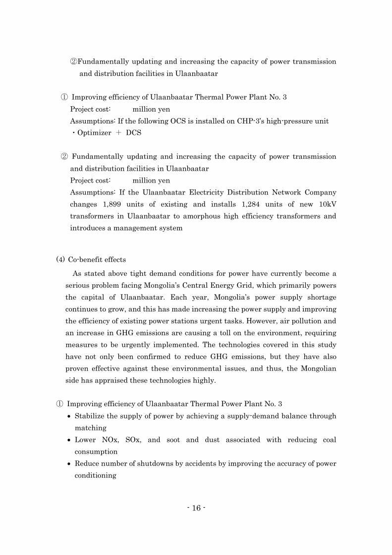
① Improving efficiency of Ulaanbaatar Thermal Power Plant No. 3
Project cost: million yen
Assumptions: If the following OCS is installed on CHP-3’s high-pressure unit
・Optimizer + DCS
② Fundamentally updating and increasing the capacity of power transmission
and distribution facilities in Ulaanbaatar
Project cost: million yen
Assumptions: If the Ulaanbaatar Electricity Distribution Network Company
changes 1,899 units of existing and installs 1,284 units of new 10kV
transformers in Ulaanbaatar to amorphous high efficiency transformers and
introduces a management system
(4) Co-benefit effects
As stated above tight demand conditions for power have currently become a
serious problem facing Mongolia’s Central Energy Grid, which primarily powers
the capital of Ulaanbaatar. Each year, Mongolia’s power supply shortage
continues to grow, and this has made increasing the power supply and improving
the efficiency of existing power stations urgent tasks. However, air pollution and
an increase in GHG emissions are causing a toll on the environment, requiring
measures to be urgently implemented. The technologies covered in this study
have not only been confirmed to reduce GHG emissions, but they have also
proven effective against these environmental issues, and thus, the Mongolian
side has appraised these technologies highly.
① Improving efficiency of Ulaanbaatar Thermal Power Plant No. 3
Stabilize the supply of power by achieving a supply-demand balance through
matching
Lower NOx, SOx, and soot and dust associated with reducing coal
consumption
Reduce number of shutdowns by accidents by improving the accuracy of power
conditioning

- 17 -
Improve operating capabilities of power plant operators (mitigate operational
burdens)
② Fundamentally updating and increasing the capacity of power transmission and
distribution facilities in Ulaanbaatar
Increase surplus supply at power plants (amount from reduced loss)
Increase transient stability of the power grid
Lower NOx and SOx emissions attributed to the reduction of coal consumption
Achieve greater grid stability by improving specifications of power
transmission and distribution facilities (reduce the number of blackouts, etc.)
(5) Identifying Needs of Power Generation, Transmission and Distribution for
Implementation at Other Cities or Facilities and Support for Project Structuring
① Energy Efficiency Improvement Diagnostics
Energy efficiency improvement diagnostics were performed on the Erdenet
Mining Company, which operates a combined heat and power facility outside of
Ulaanbaatar, in order to identify low-carbon technology projects for Japan. The
items specified in the energy efficiency improvement diagnostics for thermal
power plants are shown in Table 1.
Table 1 Diagnostic Items for Energy Efficiency Improvements
Target item Current problems Requests
Power generation
facilities (Boiler
and STG)
Plan on introducing new STG to
operate facilities based on
benchmark for heat supply needs
in the winter time
Achieve consistently
efficient operational
method throughout the
year
Coal mill Rotating type mill that consumes a
large amount of energy (50% of
power used) and soaring electricity
rates have impacted management
Reduce power
consumption through more
efficient operations
Water intake and
supply system
The pump head range is set for
water intake/supply resulting in a
large amount of power
consumption
Reduce power
consumption through more
efficient pump operations

- 18 -
Details of the items reviewed are as follows.
(i) Improve operations of power generation facilities (Boiler and STG)
The power generation facilities began operating in 1978. There are six 75t/h
boilers and two 2.5MW turbine generators. During the summer season, one
boiler is more than sufficient. In the winter season however, two are required.
Going forward, the company is looking to operate four boilers, with one a
back-up and performing inspections on another, so it plans on issuing a bid for
four 12MW turbine generators.
(ii) Energy saving of the mill
Erdenet Mining Company uses a large amount of power and it has a factory
located in the city. Erdenet Mining Company buys electricity at the highest
rates.
About 70% of power is consumed by the mill, etc. in the factory, with 20%
attributed to water supply and 10% other sources. The breakdown of the
factory’s consumption is 70% for the mill and 30% for the crusher. Nearly half of
the total power is consumed by the mill.
To make operations more energy efficient, the company will use two
Canadian motors to operate the single Chinese mill. The extent of reductions
will be studied after operations begin in April 2015.
(iii) Make the water supply pump more efficient
The water supply facility captures water from the Selenga River and supplies
1,600t/h to Erdenet Mine and Erdenet City. It has a total of five pumps
(including one reserve) at three locations. The pump head range of these pumps
is set to between 25 and 30 meters and a large amount of power is consumed to
maintain this range.
② Low-carbon technologies for the target efficiency improvement items
With regard to the above items requested for review, Table 2 contains the
potential of possible technologies and application methods mainly for the

- 19 -
implementation of technologies currently being examined for introduction in
Ulaanbaatar at other cities.
Table 2 Potential of Possible Technologies
Target item Technology potential Application method
Power generation
facilities (boiler
and STG)
Operations controlled by an
OCS
Introduce OCS and
achieve controls using an
equipment inverter
Coal mill Operations controlled by an
OCS
Introduce OCS and
achieve controls using an
equipment inverter
Water intake and
supply facilities
Pump operations controlled
by an OCS
Introduce OCS
Details of this potential are discussed below.
(i) Improve operations of power generation facilities (boiler and STG)
As with Ulaanbaatar’s CHP, the company will examine introducing an OCS
and changing pump fans over to inverters. The OCS will be used for the mill fan,
induced draft fan (IDF), and boiler feed water pump (BFP), which have large
inputs.
(ii) Make the mill more energy efficient
As with (i) above, the company will examine improving energy efficiency by
introducing an OCS. There was advice provided explaining that work would
progress smoothly if an agreement could be reached with the automated
departments of the factory.
(iii) Make the water supply pump more efficient
The water supply pump comprises five individual facilities and all four pumps,
with the exception of the reserve pump (Russian made) have been changed over
to Japanese made equipment. The pump produces between 1,360 and 1,560kW,
but the pump head range has been set at 30 meters to prevent any back flows. By
reducing the pump head range to zero after introducing an OCS, power
consumption can be reduced and energy efficiency promoted. Compared to the
power generation facilities, the pump’s operational pattern is simple, making it

- 20 -
easy to introduce an OCS, which will prove to be highly effective at reducing CO2
emissions.
A specific proposal will be drafted in the near future, but the Erdenet Mining
Company is a joint venture between Russian and Mongolian companies, meaning
that approval is necessary at a meeting that will include the Russian side as well.
Therefore, the details of the proposal must be made known to gain the
understanding of the mining company side.
Erdenet Mining Company uses a large amount of power and operates a factory
located in the city. Erdenet Mining Company purchases electricity at the highest
rates. Electricity rates have been increased around 15% annually over the past
several years. Rates tripled from 50Tg/kWh (about 3 yen) to 150T/kWh (about 9
yen) in 2007. The company consumes about 750 million kWh annually. The
copper market was robust until recently, so there was no problem on that front.
The cost of copper mining has risen annually. More and more copper is being dug
up underground with each passing year, so the rising cost of copper per ton now
necessitates the implementation of energy conservation measures.
In addition to Erdenet Mining Company, a study was carried out on the
Erdenet Combined Heat and Power Plant that is owned by the City of Erdenet
and on the combined heat and power plant located in Darkhan, the country’s
third largest city. Discussions on the introduction of OCS will be held for these
facilities, as they were for the power generation facilities of the mining company.

- 21 -
5. Review for Commercialization
(1) Commercialization/JCM Scenarios
This project targets the energy supply sector and several billions of yen in
project costs at the least will be required for power generation, transmission and
distribution. The financing scheme for realizing this project will be one that aims
to enable leap-frog development.
On June 25, 2014, Minister of the Environment Nobuteru Ishihara held talks
with Takehiko Nakao, President of the Asian Development Bank in Tokyo during
his visit to Japan, where they signed a Letter of Intent for Cooperation on
Environmental Issues. They also announced the establishment of a new trust
fund (JCM Japan Fund) utilizing JCM to support the adoption of advanced
low-carbon technologies in its developing member countries (DMCs), with a
grant of ¥1.8 billion from the Government of Japan. The flow of JCM Japan Fund
is shown in Figure 1.
Figure 1 JCM Japan Fund flow
This fund was established to mitigate additional costs with funds placed in a
trust managed by the Asian Development Bank to ensure the adoption of
advanced low-carbon technology projects, since the adoption of these types of

- 22 -
Asian Development Bank projects have not made much progress because of the
high implementation costs.
During this study, discussions with Mongolia’s Ministry of Energy and the
Ministry of Environment, Green Development and Tourism were moved forward,
and the Government of Mongolia has agreed to cooperate with the
implementation of the above project utilizing the JCM Japan Fund.
Project proceeding scheme is shown in Figure 2. The Government of Mongolia is
currently in talks with the Asian Development Bank and a framework
memorandum of understanding has already been concluded between the
Ministry of Economic Development and the Asian Development Bank for
commencing a project on power generation, transmission and distribution.
Figure 2 Project Scheme

- 23 -
(2) MRV Methodology and Monitoring System
MRV methodology and monitoring system were prepared separately for
①Improving efficiency of Ulaanbaatar Thermal Power Plant No. 3
②Fundamentally updating and increasing the capacity of power transmission
and distribution facilities in Ulaanbaatar
① Improving efficiency of Ulaanbaatar Thermal Power Plant No. 3
(i) JCM Methodology
This methodology is applied to the project that attempts to achieve GHG
emissions reductions by introducing an OCS to reduce coal consumption used
in generating steam from boilers at CHP-3.
An OCS generates an optimized operating condition where the absolute
minimum necessary amount of coal is consumed at each point in time based
on specific plant equipment data collected based on the constantly changing
conditions of the plant. Based on these results, control orders are sent to other
equipment comprising the plant through the plant control system (DCS),
which makes it possible for the plant to constantly and continuously achieve
optimized operations.
In this methodology, all relevant process data includes official data applied
to all CHP in Mongolia in order to quantitatively ascertain the reduction
amount of GHG emissions. This official data is compiled based on data
measured at each power plant each month and sent to the Ministry of Energy
(Dispatch Center). It has been determined that valid assessments of GHG
emission reductions can be carried out with official data.
The amount of GHG emissions reduced by the introduction of an OCS can be
calculated by multiplying CO2 emissions coefficient of coal by the amount of
coal consumed that was reduced by the efficiency improvements.

- 24 -
Figure 3 Improving Control Systems with OCS (Before vs. After)
(a) Definition of words
Basic words related to OCS used in this methodology are defined in Table 3.
Table 3 Definition of Terms used in Methodology
NO. Term Definition
1 Combined heat and
power plant (CHP)
A power plant, where steam produced from
multiple boiler units is supplied to multiple
turbine/generator units through the same steam
header, which can supply electricity as well as
supply steam to surrounding factories and hot
water for local heating needs by extracting steam
from the middle of the turbines.
2 CHP-3 (high pressure) The CHP plant targeted in this methodology is
the Ulaanbaatar Thermal Power Plant No. 3
(CHP-3) high pressure plant (primary steam

- 25 -
pressure of 9.8MPa) that comprises seven boilers
and five turbines/generators.
3 Optimized control system
(OCS)
A system that controls plant equipment to ensure
that the minimum necessary amount of coal is
consumed based on calculated data from the
upstream optimized computing system that
receives data from the Dispatch Center
(equivalent to the central power supply command
center) and as a result minimizes (optimizes)
total plant CO2 emissions.
4 Optimized computing
system
A system that computes deviations of the plant’s
actual operating condition from optimized
operating conditions calculated from specific data
on plant equipment at each time point, and
conveys these results to the optimized control
system.
5 Optimized control system A system that issues revised commands for the
operational condition of each plant’s equipment
based on information from the optimized
computing system in order to achieve optimized
operating conditions.
6 Distributed control
system (DCS)
As a distributed digital control system, a DCS
connects each control loop into a network and
ensures individual control loops are coordinated
with one another, while controlling applicable
equipment so that the CHP’s control targets from
the optimized control system can be met.
7 Inverter An inverter converts from DC to AC in order to
reduce energy consumption by controlling the
speed of the motors used in supplementary plant
equipment (fans/pumps) that make up part of the
OCS
8 Heat pump A piece of equipment that achieves energy
efficiency by collecting and using heat energy
from waste heat, which is more than the input

- 26 -
energy (electricity in large part, but there are
other power sources and heat).
9 Induced draft fan (IDF) An induced draft fan, or IDF, is a high capacity
fan that is used to discharge exhaust gas from
boiler furnaces through the smoke stack into the
air. Conventionally, the flow rate of IDFs were
controlled by adjusting the openness of the
damper, however, using a matrix converter, a
high efficiency inverter that has a high degree of
controllability, a larger amount of power
consumption can be reduced by controlling the
speed of the motor.
10 SFC An acronym for Specific Fuel Consumption. For
this methodology, coal consumption per unit of
electricity generated (kWh) is expressed as
SFC(E), while coal consumption per unit of heat
energy (Gcal) is expressed as SFC(H).
11 COP An acronym for Coefficient of Performance, a
coefficient used to check the energy consumption
efficiency of heat pumps. It is also often called the
performance coefficient (movement coefficient).
This value shows the cooling capacity and
heating capacity per 1kW of consumed electricity
rated based on JIS C9220.
(b) Qualification Requirements
This study anticipates that the following qualification requirements will be
set. Each of these requirements is described in Table 4.
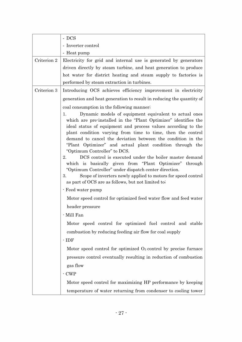
Table 4 Methodology of Qualification Requirements
Requirement
Criterion 1 The project introduces OCS to the existing grid-connected coal-fired
CHP-3 (High Pressure) plant which provides heat and electricity.
OCS consists of the following facilities in order to save coal
consumption within CHP-3 (High Pressure) plant:
- OPTIMIZER
- 27 -
- DCS
- Inverter control
- Heat pump
Criterion 2 Electricity for grid and internal use is generated by generators
driven directly by steam turbine, and heat generation to produce
hot water for district heating and steam supply to factories is
performed by steam extraction in turbines.
Criterion 3 Introducing OCS achieves efficiency improvement in electricity
generation and heat generation to result in reducing the quantity of
coal consumption in the following manner;
1. Dynamic models of equipment equivalent to actual ones
which are pre-installed in the “Plant Optimizer” identifies the
ideal status of equipment and process values according to the
plant condition varying from time to time, then the control
demand to cancel the deviation between the condition in the
“Plant Optimizer” and actual plant condition through the
“Optimum Controller” to DCS.
2. DCS control is executed under the boiler master demand
which is basically given from “Plant Optimizer” through
“Optimum Controller” under dispatch center direction.
3. Scope of inverters newly applied to motors for speed control
as part of OCS are as follows, but not limited to;
- Feed water pump
Motor speed control for optimized feed water flow and feed water
header pressure
- Mill Fan
Motor speed control for optimized fuel control and stable
combustion by reducing feeding air flow for coal supply
- IDF
Motor speed control for optimized O2 control by precise furnace
pressure control eventually resulting in reduction of combustion
gas flow
- CWP
Motor speed control for maximizing HP performance by keeping
temperature of water returning from condenser to cooling tower
- 28 -
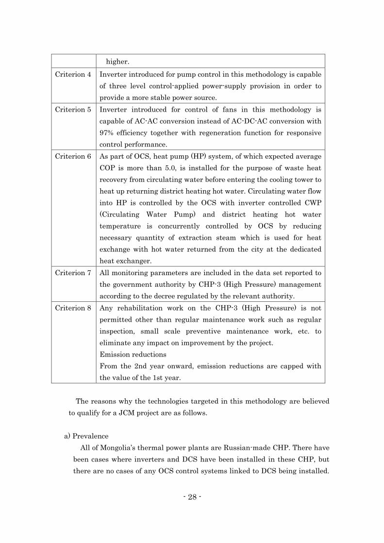
higher.
Criterion 4 Inverter introduced for pump control in this methodology is capable
of three level control-applied power-supply provision in order to
provide a more stable power source.
Criterion 5 Inverter introduced for control of fans in this methodology is
capable of AC-AC conversion instead of AC-DC-AC conversion with
97% efficiency together with regeneration function for responsive
control performance.
Criterion 6 As part of OCS, heat pump (HP) system, of which expected average
COP is more than 5.0, is installed for the purpose of waste heat
recovery from circulating water before entering the cooling tower to
heat up returning district heating hot water. Circulating water flow
into HP is controlled by the OCS with inverter controlled CWP
(Circulating Water Pump) and district heating hot water
temperature is concurrently controlled by OCS by reducing
necessary quantity of extraction steam which is used for heat
exchange with hot water returned from the city at the dedicated
heat exchanger.
Criterion 7 All monitoring parameters are included in the data set reported to
the government authority by CHP-3 (High Pressure) management
according to the decree regulated by the relevant authority.
Criterion 8 Any rehabilitation work on the CHP-3 (High Pressure) is not
permitted other than regular maintenance work such as regular
inspection, small scale preventive maintenance work, etc. to
eliminate any impact on improvement by the project.
Emission reductions
From the 2nd year onward, emission reductions are capped with
the value of the 1st year.
The reasons why the technologies targeted in this methodology are believed
to qualify for a JCM project are as follows.
a) Prevalence
All of Mongolia’s thermal power plants are Russian-made CHP. There have
been cases where inverters and DCS have been installed in these CHP, but
there are no cases of any OCS control systems linked to DCS being installed.

- 29 -
Additionally, there are, of course, no cases of any Matrix converters , being
used to control the motors of fans or the CHP, as they are only purchasable
from a Japanese manufacturer.
Furthermore, this will mark the first time that a system is used in Mongolia
where, as part of overall optimized control, Japanese-made high performance
heat pumps are used to supply exhaust heat collected in the cooling toward as
surplus heat for the return lines of hot water used for local heating.
Based on the above, a project that attempts to improve the overall efficiency
of a single CHP in Mongolia using an OCS has never taken place in the
country, and from the perspective of prevalence rate, this project is believed to
maintain sufficient qualifications as a JCM project.
b) Investment Amount and Payback Period
An investment of several billions of yen will likely be required to install the
OCS for this project. Nevertheless, this can be deemed as a realistic
investment project because of long-term low interest rate loans using the JCM
leap-frog fund and grants for advanced technologies provided by Japan’s
Ministry of the Environment.
Ultimately close to several billion yen in investment costs are anticipated. In
such a scenario, around 10% can be funded by grants, while the remaining
amount can be covered by low-interest loans, meaning there will be no initial
upfront costs for the Mongolian side, making it an extremely viable and
achievable project.
The project’s primary revenue will be the reduction in coal consumption and
the payback period anticipated for CHP-3 should be around 15 years.
c) Priority of Investment
Air pollution in Ulaanbaatar is quite serious. For example, the city’s PM10 is
279μg/m3, which is about 14 times that of Japan and roughly double of China.
A study by the Government of Mongolia found that the main factors behind
this air pollution are pollutants emitted from CHP, coal-fired heat and power
plant boilers, and wood stoves. On top of this, the city’s industry is growing

- 30 -
steadily, which has made air pollution measures an extremely important task.
Therefore, the investment priority of a project to reduce CO2 emissions by
improving the efficiency of CHP is very high and government officials as well
as other stakeholders have very high expectations for this project.
This project will also involve introducing Japan’s leading control
technologies and energy efficiency technologies, which are believed to be
qualified technologies for employing JCM.
d) Targeted GHG and Sources of Emissions
The target GHG in this methodology is CO2. The source of this CO2 is
coal-fired boilers.
This is because technologies targeted in this methodology only target
reducing coal consumption by improving power plant efficiency. Improving
power plant efficiency involves improving the efficiency of individual
equipment and recovering exhaust heat, but the power source of the heat
pump used to collect exhaust heat is the same as the power plant, so the power
grid is not considered in this situation. Therefore, the target GHG is CO2
derived entirely from coal fuel.
e) Information and Data for Computations
The data required to compute CO2 emissions considered in this
methodology is the amount of coal consumption reduced by improvements in
efficiency related to coal consumption at CHP. This amount can be calculated
from the specific unit of coal consumption reduced by efficiency improvements.
As a result, the following data is necessary.
Parameter Explanation of
data
Measurement method Basis for setting
SFC(E)RE,y Reference coal
consumption
(ton/kWh)
necessary for
the unit of
Calculated from the
multiple linear regression
analysis results of specific
unit of coal consumption
SFC(E)BP,z,i versus monthly
Because SFC(E) fluctuates
greatly month to month,
when calculating reference
values the correlation
coefficient is calculated from

- 31 -
electricity
generated
electricity generated for the
one year period prior to
project implementation.
SFC(E)BP,z,I uses official
data released monthly by
the power plant.
the multiple linear regression
analysis as a function of
parameters believed to effect
SFC(E). The reference
SFC(E) is then determined
for the project
implementation year based
on this coefficient.
SFC(H)RE,y Reference coal
consumption
(ton/Gcal)
necessary for
the unit of heat
supplied
The simple average of
specific unit of coal
consumption SFC(H)BP,z,i
versus the monthly heat
supply for a period of one
year prior to project
implementation.
SFC(H)BP,z,I uses official
data released monthly by
the power plant.
Since SFC(H) fluctuates very
little month to month, the
one-year simple average is
calculated based on the
monthly SFC(H) value for the
one year period directly
before project
implementation. Reference
SFC(H) is determined based
on this.
EGNPJ,y CHP electricity
generated in
year y of project
implementation
CHP electricity generated
for each month of the
project implementation
year.
Uses official data released
monthly by the power plant.
QHPJ,y CHP supplied
heat in year y
of project
implementation
(total of steam
supplied to
plants and hot
water supplied)
CHP supplied heat for each
month of the project
implementation year (total
of steam supplied to
factories and hot water
supplied).
Uses official data released
monthly by the power plant.
EFCO2,y Emissions
coefficient of
coal consumed
2006 IPCC Guideline

- 32 -
f) Default Value Settings
This methodology reviewed default settings for the following items.
- CO2 emissions coefficient of coal (brown coal)
The coal used at CHP-3 target of this methodology is Baganuur coal and the
following was calculated based on the 2006 IPCC Guideline:
= 25.8[tC/TJ] * 44/12 * 4.184[TJ/Tcal]*7[Gcal/ton-coal]/103 =
2.771[tCO2/ton-coal]
CHP-3 uses the same coal type as fuel and this is expected to remain the same
every year, but given the possibility that publicly released data may fluctuate
markedly, considerations will be afforded to using the latest publicly released
information as a monitoring item.
g) Method Used to Determine Preliminary Settings
Currently this method is under review and it will be set based on the results
of the next field study.
h) Calculation Basis of Reference Emissions
For this methodology, the business as usual (BaU) scenario focuses on
continuing the operations of the plant without changes, and without
implementing the efficiency improvement project. BaU emissions represent
the GHG emissions in the event that the same electricity was generated and
heat supplied assuming that the project was not implemented.
For JCM, reference emissions should be set more conservatively than BaU
emissions and given the largest discrepancy in reference emissions calculated
for this project, consideration will be made to set reference emissions
conservatively.
i) Calculation Method Used for Reference Emissions
・Reference emissions from electricity generated
A multiple linear regression analysis using the following explanatory
functions was carried out for specific unit of coal consumption SFC(E)BP,z,I
versus the monthly electricity generated for the one-year period prior to
project implementation.

- 33 -
2013 CHP-3 SFC(E )BP,z,i
Month Jan. Feb. Mar. April May June July Aug. Sept. Oct. Nov. Dec.
SFC (E) 219 225 230 242 447 533 526 529 427 302 318 311
Multiple linear regression analysis carried out with the above values using the
following explanatory functions:
Electricity generated (EGN BP,z,i)
Heat supplied for community hot water heating (QHS BP,z,i)
House electricity (for electricity generation) (HEE BP,z,i)
House electricity (for heating supply) (HEH BP,z,i)
SFC(E)BP,z,i = a * EGN BP,z,i + b * QHS BP,z,i + c * HEE BP,z,i + d * HEH BP,z,i + e
The following results were obtained from the analysis:
Result of Regression Analysis (1)
Regression statics
Correlation 0.9993
Determination 0.9987
Correction 0.9979
Result of Regression Analysis (2)
Coefficient p-value
a -0.00515 0.008819
b 0.00191 0.001924
c 0.11077 4.26E-06
d -0.05571 0.000446
e (Intercept) 270.9 6.04E-06
Result of Regression Analysis (3)
Month in 2013 Actual SFC(E) Predicted SFC(E) Error (%)
1 219.6 216.3 -1.5
2 225.5. 223.7 -0.8
3 230.5 238.9 3.6
4 242.9 247.4 1.8
5 447.7 440.3 -1.7

- 34 -
6 533.3 520.0 -2.5
7 525.5 533.0 1.4
8 529.4 536.2 1.3
9 426.9 433.7 1.6
10 301.9 297.2 -1.5
11 317.6 308.6 -2.8
12 311.1 316.9 1.7
Calculation of specific unit of coal consumption versus reference electricity
generated
Because sufficient correlation was obtained from the regression analysis, the
specific unit of coal consumption (SFC(E)RE,y,i) versus reference electricity
generated was calculated as follows using a, b, c, d, and e from above.
SFC(E)RE,y,i = a * EGN PJ,y,i + b * QHS PJ,y,i + c * HEE PJ,y,i + d * HEH PJ,y,i + e
Calculation of reference emissions for electricity generated in the project
implementation year
RE(E)y = * 0.95
= 472,303 tCO2/y
・Reference emissions from heat supply
The reference specific unit of coal consumption SFC(H)RE,y,I was calculated from
the average value of monthly heat supply for the one-year period prior to project
implementation.
= (Average value: 181.0)
RE(H)y = * 0.95
= 671,229 tCO2/y
・Reference emissions REy
The following calculation was made for reference emissions because reference
emissions (REy) equal the sum of reference electricity generated (RE[E]y) and
reference heat supply (RE[H]y).
REy= RE(E)y + RE(H)y
= 472,303 + 671,229 = 1,143,532 tCO2/y
- 35 -
The actual calculation results for the above reference emissions were reduced by
5% in order to make the value conservative.
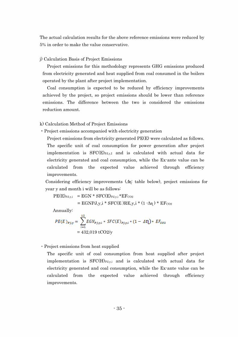
j) Calculation Basis of Project Emissions
Project emissions for this methodology represents GHG emissions produced
from electricity generated and heat supplied from coal consumed in the boilers
operated by the plant after project implementation.
Coal consumption is expected to be reduced by efficiency improvements
achieved by the project, so project emissions should be lower than reference
emissions. The difference between the two is considered the emissions
reduction amount.
k) Calculation Method of Project Emissions
・Project emissions accompanied with electricity generation
Project emissions from electricity generated PE(E) were calculated as follows.
The specific unit of coal consumption for power generation after project
implementation is SFC(E)PJ,y,I and is calculated with actual data for
electricity generated and coal consumption, while the Ex-ante value can be
calculated from the expected value achieved through efficiency
improvements.
Considering efficiency improvements (Δɳ: table below), project emissions for
year y and month i will be as follows:
PE(E)PJ,y,i = EGN * SFC(E)PJ,y,i *EFCO2
= EGNPJ,y,i * SFC(E )RE,y,i * (1 -Δɳ ) * EFCO2
Annually:
= 432,019 tCO2/y
・Project emissions from heat supplied
The specific unit of coal consumption from heat supplied after project
implementation is SFC(H)PJ,y,i and is calculated with actual data for
electricity generated and coal consumption, while the Ex-ante value can be
calculated from the expected value achieved through efficiency
improvements.

- 36 -
Considering efficiency improvements as Δɳ, project emissions for year y and
month i will be as follows:
PE(H)PJ,y,i = QHPJ,y,i * SFC(H)PJ,y,i *EFCO2
= QHPJ,y,i * SFC(H )RE,y,i *(1 -Δɳ ) * EFCO2
Annually:
= 596,647 tCO2/y
・Total annual project emissions
= 432,032 + 596,647 = 1,028,666 tCO2/y
Expected value from efficiency improvements attributed to the OCS (Δɳ)
Month Δɳ Electricity generated
(Incremental value)
Jan. 19.50% 100.0%
Feb. 14.47% 74.2%
Mar. 14.30% 73.3%
April 14.44% 74.0%
May 9.12% 46.7%
June 7.72% 39.6%
July 8.90% 45.7%
Aug. 8.81% 45.2%
Sept. 8.87% 45.5%
Oct. 14.47% 74.2%
Nov. 16.26% 83.4%
Dec. 18.81% 96.5%
l) Monitoring Methods
The required monitoring parameters for this methodology for calculating
project emissions and reference emissions after project implementation are as
follows.
(1) Electricity generated (EGNPJ,y,i)
(2) Total heat supplied (QHPJ,y,i)
(3) House electricity (for electricity generation) (HEE PJ,y,i)

- 37 -
(4) House electricity (for heating supply) (HEH PJ,y,i)
These parameters represent authoritative data released from the government
monthly as official data for CHP-3. The use of this official data is considered to
be the most valid form of monitoring data for this methodology.
m) GHG Emissions and Reduction
For this methodology, the emissions reduction was calculated from the
reference emissions calculated in j) and the project emissions calculated in k)
using the following formula.
ERy = REy - PEy
= 1,143,532 - 1,028,666 = 114,866 tCO2/y
(ii) Survey Results related to JCM PDD Preparation
(a) Project Implementation System and Project Participants
The implementation system for this project involves OECC as project
participant from the Japan side and CHP-3 as project participant from the
Mongolian side, both of which will manage the overall project. OECC will
gather and analyze information on applied technologies necessary for
preparing the PDD and data of companies involved in the project, and will
prepare the PDD. CHP-3 will provide OECC with its own data and
information on laws and regulations in Mongolia, both of which are required
for PDD preparation, and support in the preparation of the PDD.
(b) Project Commencement and Implementation Period
Operations under this project are expected to commence in 2017, and the
implementation period is expected to be 16 years.
(c) Qualification Requirements
The qualification requirements of this methodology are described in Table 5.
Table 5 Qualification Requirements in this Methodology
Details of Requirement
Criterion 1 The project introduces OCS to the existing grid-connected coal-fired
CHP-3 (High Pressure) plant which provides heat and electricity.
OCS consists of following facilities in order to save coal

- 38 -
consumption within CHP-3 (High Pressure) plant:
- Optimizer
- DCS
- Inverter control
- Heat pump
Criterion 2 Electricity for grid and internal use is generated by generators each
of which is directly driven by steam turbine, and heat generation to
produce hot water for district heating and steam supply to factories
is performed by steam extraction in turbines.
Criterion 3 Introducing OCS achieves the efficiency improvement in electricity
generation and heat generation to result in reducing quantity of
coal consumption in the following manner;
1. Dynamic models of equipment equivalent to actual ones which
are pre-installed in the “Plant Optimizer” identifies the ideal
status of equipment and process values according to the plant
condition varying from time to time, then the control demand to
cancel the deviation between the condition in the “Plant
Optimizer” and actual plant condition through the “Optimum
Controller” to DCS.
2. DCS control is executed under the boiler master demand which
is basically given from “Plant Optimizer” through “Optimum
Controller” under dispatch center direction.
3. Scope of inverters newly applied to motors for speed control as
part of OCS are as follows, but not limited to;
- Feed water pump
Motor speed control for optimized feed water flow and feed water
header pressure
- Mill Fan
Motor speed control for optimized fuel control and stable
combustion by reducing feeding air flow for coal supply
- IDF
Motor speed control for optimized O2 control by precise furnace
pressure control eventually resulting in reduction of combustion
gas flow
- CWP
Motor speed control for maximizing HP performance by keeping
temperature of water returning from condenser to cooling tower
higher.
Criterion 4 Inverter introduced for control of pumps in this methodology has
capabilities of three level control-applied power-supply provision in
order to provide a more stable power source.
Criterion 5 The inverter introduced for controlling fans in this methodology has
- 39 -
AC-AC conversion capabilities rather than AC-DC-AC conversion
capabilities, with 97% efficiency together with regeneration
function for responsive control performance.
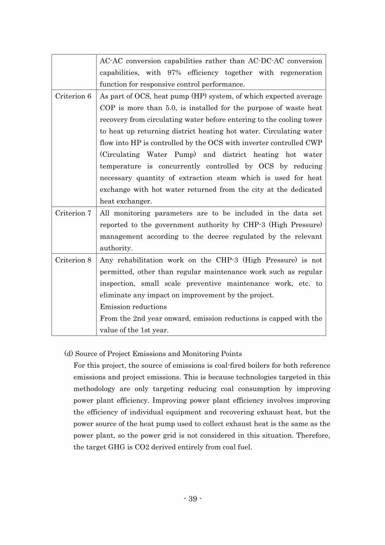
Criterion 6 As part of OCS, heat pump (HP) system, of which expected average
COP is more than 5.0, is installed for the purpose of waste heat
recovery from circulating water before entering to the cooling tower
to heat up returning district heating hot water. Circulating water
flow into HP is controlled by the OCS with inverter controlled CWP
(Circulating Water Pump) and district heating hot water
temperature is concurrently controlled by OCS by reducing
necessary quantity of extraction steam which is used for heat
exchange with hot water returned from the city at the dedicated
heat exchanger.
Criterion 7 All monitoring parameters are to be included in the data set
reported to the government authority by CHP-3 (High Pressure)
management according to the decree regulated by the relevant
authority.
Criterion 8 Any rehabilitation work on the CHP-3 (High Pressure) is not
permitted, other than regular maintenance work such as regular
inspection, small scale preventive maintenance work, etc. to
eliminate any impact on improvement by the project.
Emission reductions
From the 2nd year onward, emission reductions is capped with the
value of the 1st year.
(d) Source of Project Emissions and Monitoring Points
For this project, the source of emissions is coal-fired boilers for both reference
emissions and project emissions. This is because technologies targeted in this
methodology are only targeting reducing coal consumption by improving
power plant efficiency. Improving power plant efficiency involves improving
the efficiency of individual equipment and recovering exhaust heat, but the
power source of the heat pump used to collect exhaust heat is the same as the
power plant, so the power grid is not considered in this situation. Therefore,
the target GHG is CO2 derived entirely from coal fuel.

- 40 -
The required monitoring points for this methodology for calculating project
emissions and reference emissions after project implementation are as follows.
Electricity generated (EGNPJ,y,i)
Total heat supplied (QHPJ,y,i)
House electricity (for electricity generation) (HEE PJ,y,i)
House electricity (for heating supply) (HEH PJ,y,i)
These parameters represent authoritative data released from the government
monthly as official data for CHP-3. The use of this official data is considered to
be the most valid form of monitoring data for this methodology.
(e) Monitoring plan
The monitoring parameters expected to be used for this methodology are the
same as those presented in the item l) of (i)(b) . The field study investigated
monitoring methods, data storage methods, and monitoring system for this
data.
All monitoring parameters are contained in data reported to official
institutions (Dispatch Center) by CHP-3. This data is collected, stored and
managed following a system that has already been established within CHP-3.
It is probable that the above system will be maintained and monitoring will be
continued with this system after this project is actually installed
The required monitoring parameters for this methodology for calculating
project emissions and reference emissions after project implementation are as
follows.
Electricity generated (EGNPJ,y,i)
Total heat supplied (QHPJ,y,i)
House electricity (for electricity generation) (HEE PJ,y,i)
House electricity (for heating supply) (HEH PJ,y,i)
These parameters represent authoritative data released from the government
monthly as official data for CHP-3. The use of this official data is considered to
be the most valid form of monitoring data for this methodology.

- 41 -
The extent of equipment calibration that is taking place has yet to be
investigated, but considering the fact that the responsibility to carry out such
calibration work and the duty to report official data lies with CHP-3, it is
believed that OECC is not in a position to actively get involved in this aspect.
(f) Environmental Impact Assessment
This project involves improving efficiency of the power plant and it has
already been determined that a new environmental impact assessment does
not need to be carried out for the facility. However, a study into the details of
relevant Mongolian laws and regulations is necessary.
(g) Comments from Stakeholders
This project will be completed onsite at CHP-3 and therefore it is safe to
assume that third party stakeholders are not a component of the project.
② Fundamentally Updating and Increasing the Capacity of Power Transmission
and Distribution Facilities in Ulaanbaatar
(i) JCM Methodology
Figure 1 illustrates a quick overview of the distribution lines from power plant
to household. This methodology assumes that the distribution transformer
used in the distribution network will be updated or replaced with a high
efficiency amorphous transformer. This will greatly reduce no-load loss by
updating or replacing existing transformers that have loss (no-load loss) with
high efficiency amorphous transformers. In turn, this can also lower GHG
emissions.

- 42 -
Figure 4 Distribution Lines from Power Plant to Household
Note: Pole transformers in ④ are the target of update or replacement.
(a) Definition of Terms
Table 6 provides definitions of fundamental terms for this methodology
concerning distribution transformers used in the distribution network.
Table 6 Definition of Terms for this Methodology
Term Definition
Distribution
network
The distribution network is part of the power system installed in
order to provide electrical energy to end users. This network
supplies power at middle range voltage levels (generally higher
than 50kV).
Load loss Load loss and coil loss is loss attributed to electricity resistance
in the transformer’s winding wire. These types of loss include
eddy current loss of primary and secondary conductors in
transformers.
No-load loss No-load loss and core loss is loss due to magnetization of the
transformer’s core or from power distribution. A certain amount
of loss will occur during distribution from the transformer

- 43 -
regardless of the amount of electricity distributed.
Reference
transformer
A distribution transformer connected to the current distribution
network that has been used for at least three years and that has
an average no-load loss that is in the top 20% of average value
among data on no-load loss and load loss.
Project
transformer
A new high efficiency distribution transformer that has been
installed to replace a reference transformer or to increase the
capacity of the distribution network.
Performance
standard
A performance standard provided by a government-appointed
institution in accordance with a relevant international standard
or an independent and qualified entity that defines the
maximum level of installed transformer loss and no-load loss in a
geographic area.
Transformer
type
The type of transformer is defined based on its capacity
(kilovolt-amperes) and transformer ratio.
(b) Qualification Requirements
The qualification requirements of this methodology are described in Table 7.
Table 7 Qualification Requirements for this Methodology
Details of Requirement
Criterion 1 Replacement of Reference Transformers with Project Transformer in
the Grid, or Installation of new Project transformers in the new
areas covered by expansion of the Grid where in the absence of the
project, Reference Transformers would have been installed.
Criterion 2 No-load loss of Project Transformers is lower than that of Reference
Transformers, and Load loss of Project Transformers is not higher
than that of Reference Transformers,
Criterion 3 Project Transformers installed comply in accordance with IEC
60076 as a national / international QA/QC standards. The
certification report includes information on the measured
performance levels for load losses and no-load losses as per Standard
and in addition, the associated uncertainty
Criterion 4 A complete list of co-ordinates uniquely identifying each Project
Transformer.
- 44 -
a) Prevalence
The scope of the current study found that the Ulaanbaatar Electricity
Distribution Network Company has yet to introduce a high efficiency
amorphous distribution transformer. Below, the primary reasons why
efficiency amorphous distribution transformers have not been installed will be
examined.
b) Investment Amount and Payback Period
A capital investment of several billions of yen will likely to be required for
this project. Plans for conventional distribution equipment have been
created for each area, or as part of specific projects (residential or industrial,
etc.). Since plans and bids are determined on a project-by-project basis,
even a large-scale project will cost only several millions of yen. Whereas,
the investment amount for this project is large, which means the financing
preparations and payback period will likely take a long period of time. As a
result, without access to low interest rate JCM leap frog financing, this will
be an infrastructure project with a low feasibility.
c) Priority of Investment
Mongolia has experienced rapid growth in recent years and its
dependence on power has become more important, but priority is generally
given to investments in production facilities, while distribution
transformers are used until they breakdown or the technology is highly
dependent on outdated Russian or former Communist Bloc countries,
meaning no one wants to employ new technology, so it is believed that
investments in distribution facilities have had a low priority.
This investment situation is considered to be the norm given the fact that
distribution facilities have yet to be switched over to high efficiency models.
Based on the above, if there was no mechanism to financially support
low-carbon technologies like JCM, it is assumed that investments would
likely not be made in fields such as distribution facilities. These
technologies, which are implemented through JCM, will involve
introducing Japan’s leading energy efficiency technologies, which are
believed to be qualified technologies for JCM employment.
(c) Targeted GHG and Sources of Emissions
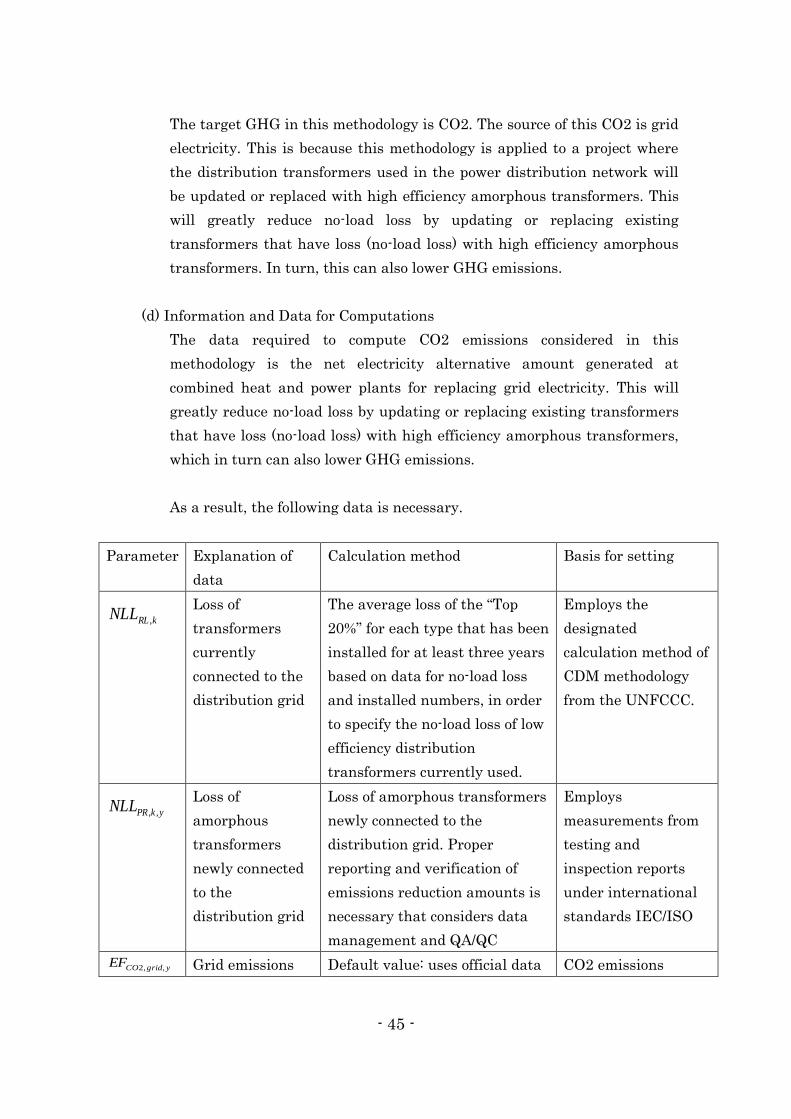
- 45 -
The target GHG in this methodology is CO2. The source of this CO2 is grid
electricity. This is because this methodology is applied to a project where
the distribution transformers used in the power distribution network will
be updated or replaced with high efficiency amorphous transformers. This
will greatly reduce no-load loss by updating or replacing existing
transformers that have loss (no-load loss) with high efficiency amorphous
transformers. In turn, this can also lower GHG emissions.
(d) Information and Data for Computations
The data required to compute CO2 emissions considered in this
methodology is the net electricity alternative amount generated at
combined heat and power plants for replacing grid electricity. This will
greatly reduce no-load loss by updating or replacing existing transformers
that have loss (no-load loss) with high efficiency amorphous transformers,
which in turn can also lower GHG emissions.
As a result, the following data is necessary.
Parameter Explanation of
data
Calculation method Basis for setting
kRLNLL ,
Loss of
transformers
currently
connected to the
distribution grid
The average loss of the “Top
20%” for each type that has been
installed for at least three years
based on data for no-load loss
and installed numbers, in order
to specify the no-load loss of low
efficiency distribution
transformers currently used.
Employs the
designated
calculation method of
CDM methodology
from the UNFCCC.
ykPRNLL ,,
Loss of
amorphous
transformers
newly connected
to the
distribution grid
Loss of amorphous transformers
newly connected to the
distribution grid. Proper
reporting and verification of
emissions reduction amounts is
necessary that considers data
management and QA/QC
Employs
measurements from
testing and
inspection reports
under international
standards IEC/ISO
ygridCOEF ,,2 Grid emissions Default value: uses official data CO2 emissions
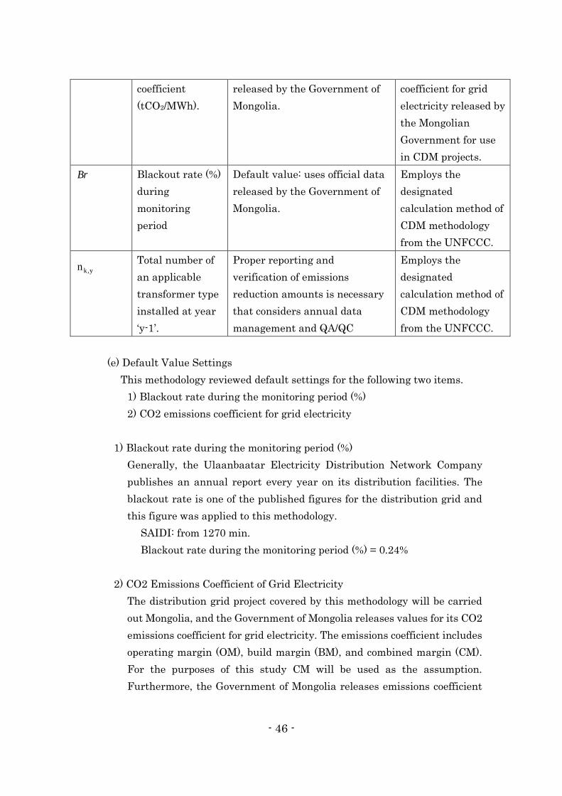
- 46 -
coefficient
(tCO2/MWh).
released by the Government of
Mongolia.
coefficient for grid
electricity released by
the Mongolian
Government for use
in CDM projects.
Br Blackout rate (%)
during
monitoring
period
Default value: uses official data
released by the Government of
Mongolia.
Employs the
designated
calculation method of
CDM methodology
from the UNFCCC.
y,kn
Total number of
an applicable
transformer type
installed at year
‘y-1’.
Proper reporting and
verification of emissions
reduction amounts is necessary
that considers annual data
management and QA/QC
Employs the
designated
calculation method of
CDM methodology
from the UNFCCC.
(e) Default Value Settings
This methodology reviewed default settings for the following two items.
1) Blackout rate during the monitoring period (%)
2) CO2 emissions coefficient for grid electricity
1) Blackout rate during the monitoring period (%)
Generally, the Ulaanbaatar Electricity Distribution Network Company
publishes an annual report every year on its distribution facilities. The
blackout rate is one of the published figures for the distribution grid and
this figure was applied to this methodology.
SAIDI: from 1270 min.
Blackout rate during the monitoring period (%) = 0.24%
2) CO2 Emissions Coefficient of Grid Electricity
The distribution grid project covered by this methodology will be carried
out Mongolia, and the Government of Mongolia releases values for its CO2
emissions coefficient for grid electricity. The emissions coefficient includes
operating margin (OM), build margin (BM), and combined margin (CM).
For the purposes of this study CM will be used as the assumption.
Furthermore, the Government of Mongolia releases emissions coefficient

- 47 -
data for both Ex-ante (value used when finalizing the emissions coefficient
in advance) and Ex-post (value used when the coefficient fluctuates each
year after project implementation). The methodology spreadsheet used for
this methodology assumes that the coefficient value is finalized and
approved in advance, so it uses the Ex-ante value. Specifically, the
following values are used.
ygridCOEF ,,2 =Emission Factor of the grid (tCO2e/ MWh)
Emissions Factor of Mongolia’s power grid: 1.154 (CES Central Energy
Grid, 2010)
(f) Method Used to Determine Preliminary Settings
As stated above, this methodology employed the following settings for the
following two items per the results of the review.
1) Blackout rate during the monitoring period (%)
The Ulaanbaatar Electricity Distribution Network Company publishes an
annual report every year. The blackout rate is one of the published figures
for the distribution grid and this figure was applied to this methodology.
SAIDI: from 1270 min.
The value will be set in advance for projects in each fiscal year based on
the value from the particular fiscal year.
2) CO2 emissions coefficient for grid electricity
The emissions coefficient for CDM released by the Government of
Mongolia was used as the default value. This methodology focuses on
principal grid electricity in Mongolia and project participants using this
methodology will select grid electricity for the project to connect and used
as an alternative as the parameter of “grid” when preparing the PDD.
Selecting grid electricity on the monitoring plan spreadsheet will
automatically set the corresponding emissions coefficient.
(g) Calculation Basis of Reference Emissions
For this methodology, the business as usual (BaU) scenario focuses on
continuing the operations of the plant, while BaU emissions represent the
GHG emissions in the event that the same amount of electricity as
generated by the project was obtained from grid electricity. For JCM,
reference emissions should be set more conservatively than BaU emissions

- 48 -
and while there is a method to lower the emissions coefficient of generated
electricity or grid electricity in this type of project, it is difficult to support
the basis or rationality of setting a discount value for the emissions
coefficient of grid electricity. Therefore, this methodology employs a method
to conservatively calculate generated electricity, or net electricity
generated from the project (self-consumed electricity).
Therefore, the reference emissions for this methodology is calculated by
multiplying the emissions coefficient of grid electricity by the average value
of the group in the “Top 20%” of the conservative calculation and the
electricity emissions of the net reduction from the project per the actual
plant testing results.
(h) Calculation Method Used for Reference Emissions
In order to specify no-load loss values for low efficiency distribution
transformers used until now, the average loss value of the “Top 20%” for
each type obtained from data on the number and load loss of transformers
that have been installed for at least three years can be used as an
alternative to grid electricity. As a result, this methodology calculates net
alternative electricity amounts using the following method.
(i) Calculation Basis of Project Emissions
For this methodology, project emissions are calculated by multiplying the
emissions coefficient of grid electricity by the electricity emissions of the net
reduction from the project per the actual plant testing results.
(j) Calculation Method Used for Project Emissions
For the above reason, the following formula is used to calculate project
emissions.
(k) Monitoring Methods
Under this methodology, emissions are calculated by multiplying the
emissions coefficient of grid electricity by the average value of the group in
the “Top 20%” of the conservative calculation and the electricity emissions
of the net reduction from the project per the actual plant testing results.
Therefore, the parameters used for monitoring will be electricity emissions
of the net reduction from the project per the actual plant testing results and

- 49 -
the number of upgraded or added transformers for each type and each fiscal
year. No special methods or technologies are believed to be required for
continuously measuring the total cumulative amount of electricity
generated.
It is anticipated that a certificate of screening will be obtained for this
project from an IEC standards compliant manufacturer. Additionally, the
frequency of calibration will be examined based on the use of a
manufacturer’s specifications and warranty.
(l) GHG Emissions and Reduction
The emissions reduction amount for this project will be calculated by
subtracting project emissions [PEy] from reference emissions [REy].
Specifically, the following formula will be used for the calculation.
yyy PEREER
Year Estimated Reference
emissions (tCO2e)
Estimated Project
Emissions (tCO2e)
Estimated Emission
Reductions (tCO2e)
2017 20,710 6,282 14,429
2018 20,710 6,282 14,429
2019 20,710 6,282 14,429
2020 20,710 6,282 14,429
Total (tCO2e) 82,840 25,128 57,716
(ii) Survey Results related to JCM PDD Preparation
(a) Project Implementation System and Project Participants
The implementation system for this project involves Power Systems
Company as project participant from the Japan side and Ulaanbaatar
Energy Distribution Network Company as project participant from the
Mongolian side, both of which will manage the overall project. OECC will
gather and analyze information on applied technologies necessary for
preparing the PDD and data of companies involved in the project, and will
prepare the PDD. Ulaanbaatar Energy Distribution Network Company will
provide to OECC its own data and information on laws and regulations in
Mongolia, both of which are required for PDD preparation, and support in
the preparation of the PDD.

- 50 -
(b) Project Commencement and Implementation Period
Operations for this project are expected to commence in 2017 and the
implementation period is expected to be at least 7 years.
(c) Ensuring Consistency with Qualification Requirements
The qualification requirements of this methodology are described in Table 8.
Table 8 Qualification Requirements for this Methodology
Details of Requirement
Criterion 1 Replacement of Reference Transformers with Project Transformer in
the Grid, or Installation of new Project transformers in the new
areas covered by expansion of the Grid where in the absence of the
project, Reference Transformers would have been installed.
Criterion 2 No-load loss of Project Transformers is lower than that of Reference
Transformers, and Load loss of Project Transformers is not higher
than that of Reference Transformers.
Criterion 3 Project Transformers installed comply with in accordance with IEC
60076 as a national/ international QA/QC standards. The
certification report includes information on the measured
performance levels for load losses and no-load losses as per Standard
and in addition, the associated uncertainty.
Criterion 4 A complete list of co-ordinates uniquely identifying each Project
Transformers.
(d) Source of Project Emissions and Monitoring Points
The target GHG in this methodology is CO2. The source of this CO2 is grid
electricity, because this methodology is applied to a project where the
distribution transformers used in the power distribution network will be
updated or replaced with high efficiency amorphous transformers. This will
greatly reduce no-load loss by updating or replacing existing transformers
that have loss (no-load loss) with high efficiency amorphous transformers.
In turn, this can also lower GHG emissions.
The necessary data for calculating CO2 emissions considered in this
methodology is the net electricity alternative amount generated at
combined heat and power plants for replacing grid electricity. This will
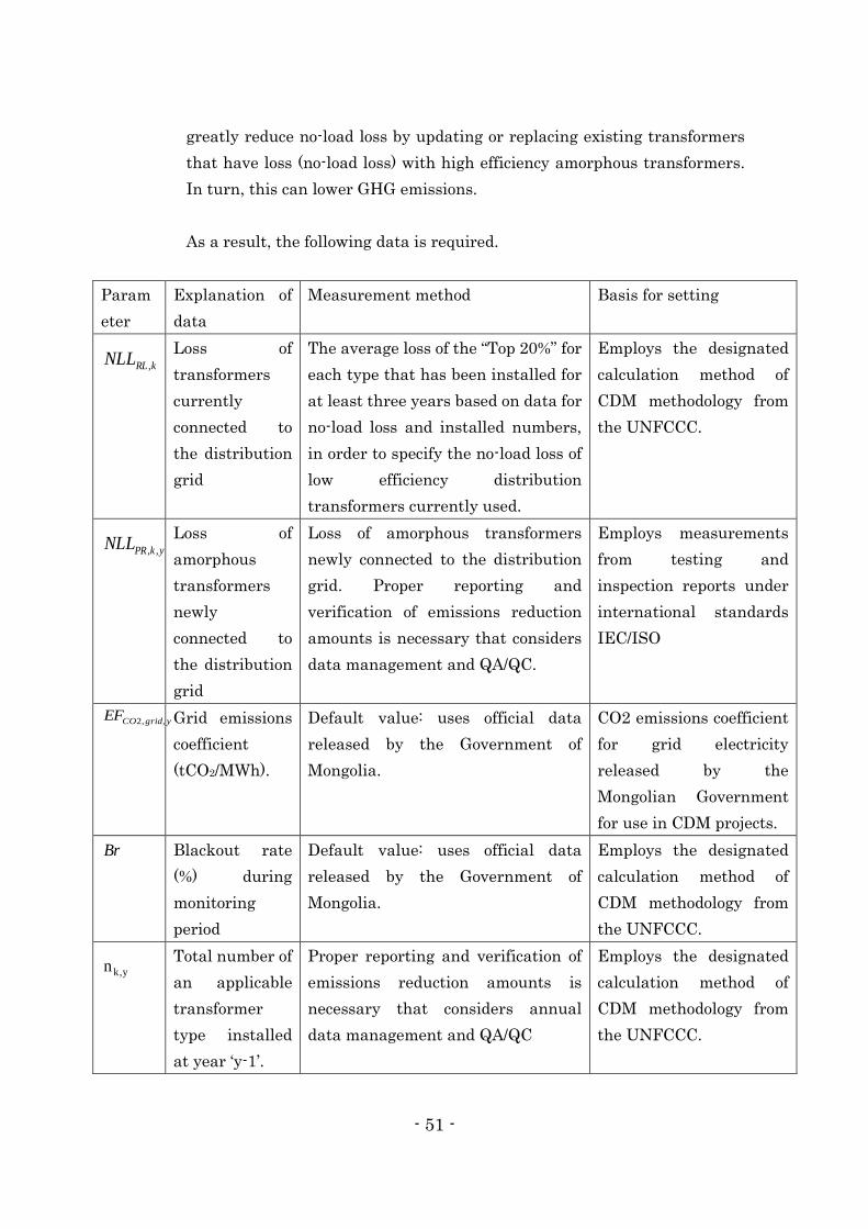
- 51 -
greatly reduce no-load loss by updating or replacing existing transformers
that have loss (no-load loss) with high efficiency amorphous transformers.
In turn, this can lower GHG emissions.
As a result, the following data is required.
Param
eter
Explanation of
data
Measurement method Basis for setting
kRLNLL ,
Loss of
transformers
currently
connected to
the distribution
grid
The average loss of the “Top 20%” for
each type that has been installed for
at least three years based on data for
no-load loss and installed numbers,
in order to specify the no-load loss of
low efficiency distribution
transformers currently used.
Employs the designated
calculation method of
CDM methodology from
the UNFCCC.
ykPRNLL ,,
Loss of
amorphous
transformers
newly
connected to
the distribution
grid
Loss of amorphous transformers
newly connected to the distribution
grid. Proper reporting and
verification of emissions reduction
amounts is necessary that considers
data management and QA/QC.
Employs measurements
from testing and
inspection reports under
international standards
IEC/ISO
ygridCOEF ,,2
Grid emissions
coefficient
(tCO2/MWh).
Default value: uses official data
released by the Government of
Mongolia.
CO2 emissions coefficient
for grid electricity
released by the
Mongolian Government
for use in CDM projects.
Br Blackout rate
(%) during
monitoring
period
Default value: uses official data
released by the Government of
Mongolia.
Employs the designated
calculation method of
CDM methodology from
the UNFCCC.
y,kn
Total number of
an applicable
transformer
type installed
at year ‘y-1’.
Proper reporting and verification of
emissions reduction amounts is
necessary that considers annual
data management and QA/QC
Employs the designated
calculation method of
CDM methodology from
the UNFCCC.
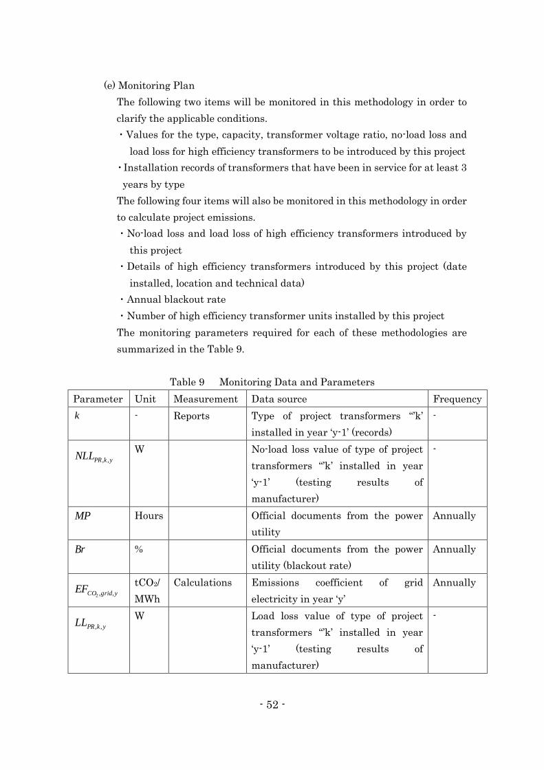
- 52 -
(e) Monitoring Plan
The following two items will be monitored in this methodology in order to
clarify the applicable conditions.
・Values for the type, capacity, transformer voltage ratio, no-load loss and
load loss for high efficiency transformers to be introduced by this project
・Installation records of transformers that have been in service for at least 3
years by type
The following four items will also be monitored in this methodology in order
to calculate project emissions.
・No-load loss and load loss of high efficiency transformers introduced by
this project
・Details of high efficiency transformers introduced by this project (date
installed, location and technical data)
・Annual blackout rate
・Number of high efficiency transformer units installed by this project
The monitoring parameters required for each of these methodologies are
summarized in the Table 9.
Table 9 Monitoring Data and Parameters
Parameter Unit Measurement Data source Frequency
k - Reports Type of project transformers “’k’
installed in year ‘y-1’ (records)
-
ykPRNLL ,,
W No-load loss value of type of project
transformers “’k’ installed in year
‘y-1’ (testing results of
manufacturer)
-
MP Hours Official documents from the power
utility
Annually
Br % Official documents from the power
utility (blackout rate)
Annually
ygridCOEF ,,2
tCO2/
MWh
Calculations Emissions coefficient of grid
electricity in year ‘y’
Annually
ykPRLL ,, W Load loss value of type of project
transformers “’k’ installed in year
‘y-1’ (testing results of
manufacturer)
-
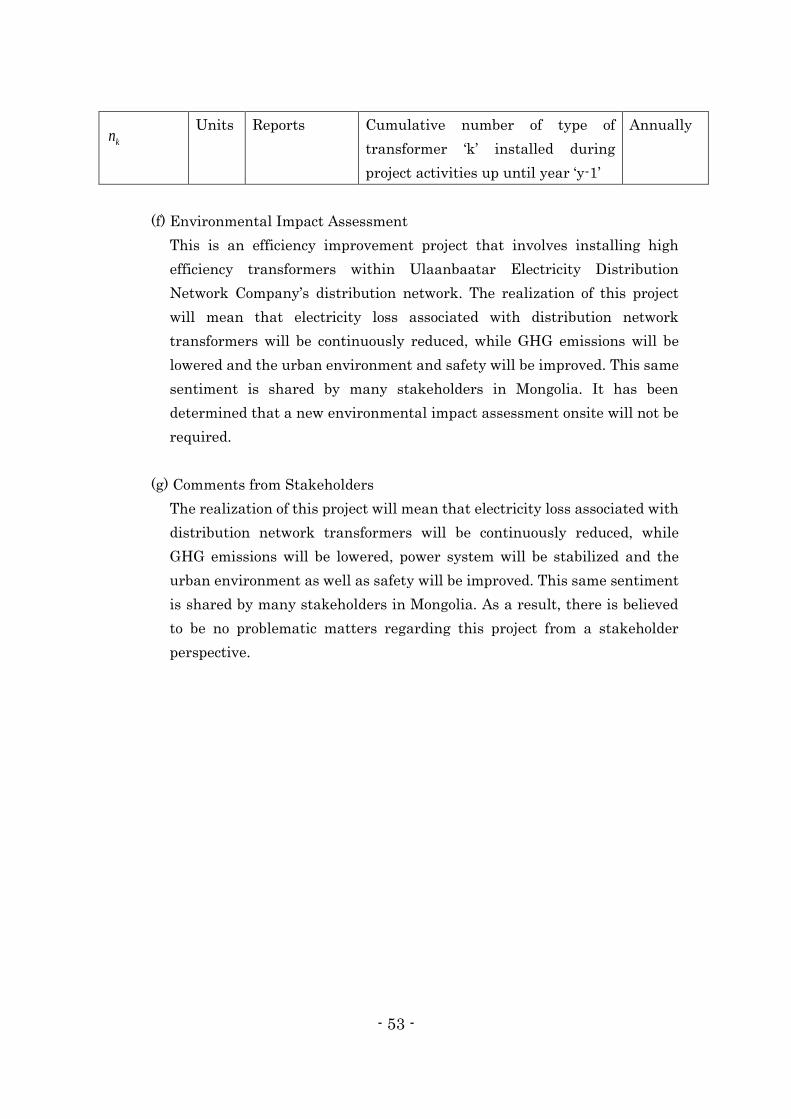
- 53 -
kn
Units Reports Cumulative number of type of
transformer ‘k’ installed during
project activities up until year ‘y-1’
Annually
(f) Environmental Impact Assessment
This is an efficiency improvement project that involves installing high
efficiency transformers within Ulaanbaatar Electricity Distribution
Network Company’s distribution network. The realization of this project
will mean that electricity loss associated with distribution network
transformers will be continuously reduced, while GHG emissions will be
lowered and the urban environment and safety will be improved. This same
sentiment is shared by many stakeholders in Mongolia. It has been
determined that a new environmental impact assessment onsite will not be
required.
(g) Comments from Stakeholders
The realization of this project will mean that electricity loss associated with
distribution network transformers will be continuously reduced, while
GHG emissions will be lowered, power system will be stabilized and the
urban environment as well as safety will be improved. This same sentiment
is shared by many stakeholders in Mongolia. As a result, there is believed
to be no problematic matters regarding this project from a stakeholder
perspective.

- 54 -
(3) Implementation Plan and Detailed Schedule
① Improving efficiency of Ulaanbaatar Thermal Power Plant No. 3
Going forward, specifications of the system to be introduced will be finalized in
cooperation with CHP-3 and the Government of Mongolia and the necessary
procedures for using the JCM Japan Fund will also be carried out.
Of the specific technologies being introduced by this project, similar needs
have been confirmed for the introduction of OCS at power plants or reuse of
heat energy using a heat pump system, for example, at power plants and
factories in Mongolia, such as CHP-4, a combined heat and power plant in
Ulaanbaatar, and at the power plant operated by the Erdenet Mining
Company. Consequently, similar solutions will be rolled out next fiscal year at
other domestic cities. These technologies can also be applied at power plants
in other countries as well. A review will be made into the potential for
expanding these solutions in other Asian countries.
③ Fundamentally updating and increasing the capacity of power transmission
and distribution facilities in Ulaanbaatar
Ulaanbaatar Energy Distribution Network Company and the Ministry of
Energy of the Government of Mongolia are moving forward with plans to
upgrade more than 1,000 existing state-owned distribution facilities. Moving
forward, this project will target more than just upgrades to existing
distribution facilities by rolling out solutions at distribution facilities in newly
zoned areas under Ulaanbaatar’s urban plan. Specifically, Ulaanbaatar plans
on newly developing 54 zones, and to achieve this goal.

- 55 -
Abbreviation List
Abbreviation Proper Name
BaU Business as Usual
BTG Boiler, Steam Turbine and Generator
CDM Clean Development Mechanism
CHP Combined Heat and Power Plant
CHP-3 Ulaanbaatar No.3 Combined Heat and Power Plant
CHP-4 Ulaanbaatar No.4 Combined Heat and Power Plant
COP Conference of the Parties
COP Coefficient of Performance
tCO2 ton-CO2
CWP Circulating Water Pump
DCS Distributed Control System
GHG Greenhouse effect gas
IDF Induced Draft Fan
JCM Joint Credit Mechanism
MEGDT Mongolia Ministry of Environment, Green Development
and Tourism
MOE Mongolia Ministry of Energy
MRV Measurement, Reporting and Verification
またはMeasurable, Reportable and Verifiable
NAMA Nationally Appropriate Mitigation Action
OCS Optimized Control System
PDD Project Design Document
SFC Specific Fuel Consumption
STG Steam Turbine and Generator
UBEDN Ulaanbaatar Electricity Distribution Network Company
UNFCCC United Nations Framework Convention on Climate Change