feasibility study for developing future jcm project … feasibility study project for the jcm (fy...
TRANSCRIPT

1
Feasibility Study project for the JCM
(FY 2014)
“Feasibility Study for developing future JCM
project applying effective Japanese excellent
energy saving technologies
to Vietnam Steel Industry “
Report
March, 2015
JFE Techno-Research Corporation
JFE Steel Corporation

Table of contents
1. The Purpose of the Project...................................................................................................1
2. Present conditions of the steel industry in Vietnam and Study of the energy-saving
technologies .............................................................................................................................2
2.1 Present conditions of steel Industry and Energy situation in Vietnam ............................2
2.1.1 present conditions of the steel industry in Vietnam..................................................2
2.1.2 Energy situation in Vietnam.................................................................................3
2.1.3 Energy consumption condition of steel industry in Vietnam.....................................3
2.2 The Technologies Positive List .......................................................................................6
2.2.1 Overview of Electric Furnace Steel Mill....................................................................6
2.2.2 Superior Energy Saving Technologies at EAF Steel Mills in Japan.........................7
(1) Energy Saving Technologies for EAF Steelmaking Method ....................................8
(2) Energy Saving Technologies for RHF....................................................................10
2.2.3 The Positive List of Energy Saving Technologies for Electric Furnace Steelmaking
in Vietnam .......................................................................................................................11
(1) Energy Saving Technologies Regarding EAF Steelmaking (No.1 - 12): ................12
(2) Energy Saving Technologies Regarding RHF (No.13 - 16): ..................................19
(3) Other Energy Saving Technologies (No.17 – 18): .................................................21
3. The Reviews on the Specific Project Planning for Commercialization ...............................25
3.1 The Review on the Specific Project Planning for A-Company......................................27
3.1.1 Overview of A-Company ........................................................................................27
3.1.2 Specification of Issues on Energy Saving to study ................................................29
3.1.3 Diagnosis on Energy Saving Issues and Estimation of Applicable Technologies..30
(1) Study of energy saving technologies for the EAF: .................................................30
(2) Study of fuel consumption reduction for the RHF: .................................................35
3.2 The Review on the Specific Project Planning for B-Company......................................43
3.2.1 Overview of B-Company ........................................................................................43
3.2.2 Specification of Issues on Energy Saving to study ................................................44
(1) Study of energy saving technologies for EAF ........................................................45
(2) Study of fuel consumption reduction for ladle furnace ...........................................49
(3) Study of fuel consumption reduction for RHF ........................................................51
3.3 Estimation of Energy Saving and CO2 Reduction rate, and Economical Evaluation ...55
3.3.1 Estimation of Energy Saving and CO2 Reduction rate, and Economical Evaluation
for A-Company ................................................................................................................55
(1) Estimation of Energy Saving rate and CO2 Reduction rate ...................................56
(2) Estimation of economical condition........................................................................57
3.3.2 Estimation of Energy Saving and CO2 Reduction rate, and Economical Evaluation
for B-Company ................................................................................................................58

(1) Estimation of Energy Saving rate and CO2 reduction rate ....................................59
(2) Estimation of economical condition........................................................................61
3.4 Finantial Scheme in Vietnam........................................................................................63
4. JCM methodology ..............................................................................................................66
4.1 Joint Crediting Mechanism Methodology of “Energy Saving by Introduction of Optimum
Power Regulation System at Electric Arc Furnace”............................................................67
4.2 Methodology of Ladle Preheating Oxygen/Fuel Burner................................................79
4.3 Joint Crediting Mechanism Methodology of “Introduction of Regenerative Burner to the
Reheating furnace for Semi-processed Steel”....................................................................90
5. Reporting of Energy Saving Technologies to Vietnam.......................................................99
5.1 Prior explanation to the government officials................................................................99
5.2 Seminar in Hanoi ........................................................................................................100
6. Economical Analysis for Commercialization.....................................................................103
7. Summery ..........................................................................................................................108
7.1 Policy reccomendation on JCM in Vietnam ................................................................108
7.2 Summery, Suggestion and Proposal for the activity for next fiscal year.....................110
Annex1 Commentary on technologies positive list ...........................................................112

1
1. THE PURPOSE OF THE PROJECT
Japan has been working for solving the climate change issue, and has developed a lot of superior
technologies and products applicable to reducing greenhouse gas emissions overseas. “The Clean
Development Mechanism (CDM)” is now the sole global framework available for us to contribute to
reduction of greenhouse gas emissions in developing countries by promoting these technologies and
products. But there are still relatively few cases where those countries have adopted our low-carbon
technologies which are ones of Japan’s major strengths, such as the energy-saving technologies, the
new energy technologies, the technologies for high efficiency coal-fired power generation, etc.
Moreover, the CDM is difficult for smaller developing countries to utilize its system as it requires
difficult procedures and its validation process is complicated, and therefore it is insufficient
framework for Japan to contribute widely to reduction of greenhouse gas emissions in developing
countries by promotion of our low-carbon technologies and products.
The government of Japan has been building “the Joint Crediting Mechanism (JCM)” as a
complementary system for the CDM in order to push forward the global warming mitigation on a
worldwide scale by aggressive promotion of spreading the Japan’s world-class low-carbon
technologies and products in developing countries.
Japan signed the bilateral document for the JCM with countries in Asia and Africa, some of the
countries have started the implementations, and they are looking forward to the JCM and the spread of
the Japan’s low-carbon technologies.
This study includes introduction of Japan’s superior technologies to the steel industry in the Socialist
Republic of Vietnam (hereinafter referred to as “Vietnam”), field survey at two sites of steelworks in
the country, applicability study of the energy-saving technologies to the Vietnamese steel industry,
evaluation of cost performance and amount of CO2 reduction, and applicability study of the JCM.

2
2. PRESENT CONDITIONS OF THE STEEL INDUSTRY IN
VIETNAM AND STUDY OF THE ENERGY-SAVING
TECHNOLOGIES
2.1 PRESENT CONDITIONS OF STEEL INDUSTRY AND ENERGY SITUATION IN
VIETNAM
2.1.1 PRESENT CONDITIONS OF THE STEEL INDUSTRY IN VIETNAM
Figure 2.1-1 shows the trend of steel consumption, steel production and steel self sufficient ratio
in this decade in Vietnam. Steel consumption grew to double from 2004 through 2011 backed by
high growth of the economy of Vietnam. The government tight-money policy for inflation restraint
in 2011 collapsed a real-estate bubble and forced to slow down the steel consumption, but it
gradually increases again recently. The increasing rate of production exceeds that of consumption
from 2004 through 2011, and the self-sufficiency ratio tends to increase. In 2012 and 2013, the
self-sufficiency ratio decreases slightly, because low-priced import steel from China in particular
has increased.
0
2,000
4,000
6,000
8,000
10,000
12,000
14,000
16,000
2004 2005 2006 2007 2008 2009 2010 2011 2012 2013
Ste
el Cosu
mpt
ion, C
rude
Ste
el pr
odu
ct
steel
0%
5%
10%
15%
20%
25%
30%
35%
40%
45%
50%
Self sufficient
Steel Cosumption
Crude Steel production
Self sufficient ratio
Figure 2.1-1 Transition of crude steel production rate, steel consumption rate and self sufficient
ratio1
One major issue of the steel industry in Vietnam includes imbalance between supply and demand.
Productive capacity of some products such as rebar and rod becomes superabundant.
1 Based on the data of worldsteel ”Steel Statistical Yearbook 2014”

3
Another major issue is the production cost. Outdated and small facilities are still left, and at the same
time new facilities have started in operation after 2000. It is said that old facilities cannot show their
efficiency, and new facilities cannot handle them sufficiently. This situation cannot control
competitive production cost. Meanwhile electric power price in Vietnam has been held down
politically. At present electric power price is 6 ~7 US cents/kwh, but it will be raised to 8 ~9 US
cents/kwh in 2020 according to Master Plan. On the other hand, low price steel from China tends to
increase. In order to overcome this situation, cost down of the steel production must be required from
now.
2.1.2 ENERGY SITUATION IN VIETNAM
Steel industry is one of the big energy consumng industry, and its energy saving activity can
contribute to big CO2 reduction. On the otherhand, profitability is important to introduce energy
saving technologies. Steel companies in Vietnam generally posess Electric Arc Furnace (hereinafter
referred to as “EAF”) and Reheating furnace (hereinafter referred to as “RHF”). EAF mainly
consumes electric power, and RHF maily consumes fuel such as coal, oil, natural gas etc. Accordingly
energy prices are key factor for production of steel..
Vietnam is blessed with energy resources, and the production of oil, natural gas, coal is an big scale
in the Southeastern Asian area. However, with recent economic growth, the energy demands increase
rapidly, and all these resources must be improted in the near future.
The master plan2 says that electric power price will be raised to 8~9 US Cents/kwh. Oil, natural gas,
and coal will be expected to be raised too. For example2 coal prices will be raised to 15% by 2020.
As mentioned above, in 2020 it is expected that electric power price will be raised by 30%, and oil,
natural gas, and coal will be raised by 15%.
2.1.3 ENERGY CONSUMPTION CONDITION OF STEEL INDUSTRY IN VIETNAM.
Through documents and a field work, the amount of energy saving and CO2 reduction potentials are
calculated when Japanese technologies are introduced.
UNIDO Vietnam Mission Report3 in 2011 and UNIDO Seminar4 in 2012 show energy intensity
(GJ/t-steel) and CO2 emission rate (kg-CO2/t-steel) of 18 steel companies joining Vietnam steel
association. Fig.2.1-2 shows both average value of CO2 emission and specific electric power
consumption calculated from energy intensity. CO2 emission and specific electric power consumption
is assumed to be almost 1.5 times as much as that of Japan.
In Figure 2.1-3, operation conditions and their operational indecis are arranged.
2 JETRO Hanoi Center March, 2011 3 UNIDO, "Energy and Resource Efficiency in the Vietnamese Steel Industry", July 2011 4 Green Industry Initiative and Promotion of Green Technologies 20120828-Green_Industry.pdf, (UNIDO Seminar, Tokyo (2012))

4
0
200
400
600
800
1000
1200
1400
1600
L E O M K Q G J N A H D P I F C R B Average Japan
Ele
ctr
ic p
ow
er,
、C
O2 E
mis
sion
Electric power, kWh/t-liquid steel (2011/7)
Electric power, kWh/t-liquid steel (updatedbaseline, 2012/8)
CO2, kg-CO2e/t-steel billet(2011/7)
(Hot metal ratio/50%)
Figure 2.1-2 Specific electric power consumption and CO2 emission rate of 18 steel companies
joining Vietnam Steel Association
(Unit of data in Japan is expressed as “per t-steel billet”)

5
Figure 2.1-3 EAF operation condition and its operational index of 18 steel companies joining Vietnam Steel Association
Production,x10,000t/y
EAFCapacity
,t/ch
SPH EBT CoolingPane
LadleFurnac
e
Warmor Hotcharge
EAF electric powerconsumption
,GJ/t-liquid steel(2011/7)
EAF electric powerconsumption,kWh/t-steel(2011/7) *3
EAF electricpower
consumption,kWh/t-steel
(2012/8) *8, *3
CC energyConsumptio
nGJ/t-billet
RHF EnergyconsuptionGJ/t-billet
EAFElectrode
consumption
kg/t-billet
Tap totap
,min
CO2Emission Factor*2
,kg CO2e/t-steel
1 A Private 20 15-20 × × × ○ ○ 2.7 540 672 0.5 1.5 3.4 96 690 Stage-1less advancedplant, fig4
2 B Private 25 60 ○ ○ ○ ○ × 4.1 820 706 0.4 no mill 2.7 60 1,180 Stage-1more advancedplant, fig4,10
3 C Public 7 15-20 × × × × × 3.45 690 754 0.2 no mill 4.1 70 930 Stage-1less advancedplant, fig4
4 D Public 10 15-20 × × × ○ ○ 3.1 620 602 0.3 1.6 3.1 80 720 Stage-1less advancedplant, fig4
5 E Private 45 60 ○ ○ ○ ○ ○ 2.1 420 717 0.2 1.2 1.45 60 620 Stage-1more advancedplant, fig4,10
6 F Public 50 60 ○ ○ ○ ○ × 3.3 660 593 0.3 1.7 1.35 45 820 Stage-1more advancedplant, fig4,10
7 G Public 2.6 520 564 3.8 150 520 Stage-2
8 H Public 3.1 620 660 2.6 75 1,450 Stage-2Hot metalratio50%,fig19, HP
9 I Public 3.25 650 646 5.8 158 780 Stage-2
10 J Private 2.6 520 655 3.3 110 790 Stage-2
11 K Private 2.55 510 586 3.3 80 720 Stage-2
12 L Private 2 400 459 2.7 80 530 Stage-2
13 M Private 2.55 510 561 3 90 580 Stage-2
14 N Private 2.6 520 593 3.15 110 620 Stage-2
15 O Private >50 2.2 440 494 2.7 76 750 Stage-2more advancedplant, fig4,10
16 P Public 3.15 630 684 2.25 56 800 Stage-2
17 Q Private 2.6 520 586 3 80 590 Stage-2RHF:CGF、lowproduction/ Fig18
18 R Private 3.8 760 892 4 120 930 Stage-2
min 2.0 400 1.2 1.4 45 520max 4.1 820 1.7 5.8 158 1450ave 2.9 575 1.5 3.1 89 779
380 *4 0.6-1.2 *6 530 *51.7 *1 345 *7 0.3 *1 0.5 *1 1.1 *7
Fig21 Fig5,6Table2
Fig5,6,10p.9 p.9 p.9
Table7,Fig17
p.9 Fig5,6,7,9,21 Table2 Table2 Fig17Fig12Table4
Fig20
Reference 2 *1
Operation Condition Operation Index
Plant*1
Average of 18companies
(Oxygen consumption=30~50Nm3/t-steel *3)
NoReference 1
*1
Japan levelworld revel
UNIDO Report *1→
*1: UNIDO, "Energy and Resource Efficiency in the Vietnamese Steel Industry", July 2011, *2: Total on and off site emissions *3: From Nguyen Thi Ngoc Tho (Energy Efficiency and Conservation Center of Ho Chi Minh City) "Overview of Steel and Paper Industry – Energy Saving Potential"2012,
and *1 (calculated with using 5.0GJ/MWh)。 *4: Handbook of Iron and Steel 5th edition, the 1st volume p.322 (2014), *5: Ferrum Vol.3 (1998) No.1, *6: Handbook of Iron and Steel 5th edition, the 6th volume p.216 (2014) *7: P.Dahlmann, R.Fandrich and H.B.Lüngen: Stahl Eisen, 132(2012), Nr.10, 29 *8: Green Industry Initiative and Promotion of Green Technologies 20120828-Green_Industry.pdf, (UNIDO Seminar, Tokyo (2012))

6
2.2 THE TECHNOLOGIES POSITIVE LIST
We selected here the proposals for energy saving technologies which are effective in applying to the
Vietnamese steel industry by careful study and organization of the energy saving technologies for
EAF steelmaking mainly in Japan, and by comparison with such lists as 'the List of Energy-Saving
Technologies’ which is one of the deliverables from “the Global Warming Mitigation Technology
Promotion Project” so far. The Positive List has been drawn up simultaneously with and is
substantially similar to the Customized List of “the Promotion of ISO14404 (Calculation method of
carbon dioxide (CO2) emission intensity from iron and steel production)” in the FY2014
“Fundamental Projects on International Standardization and Dissemination of Energy Savings (Joint
Research and Development and Promotion of International Standards on Energy Savings)”.
In the following, we explain a basic process for an EAF steel mill, the Positive List in which the
proposals for effective energy saving technologies are listed, and the technologies in the List which
are subject to application examination in this study.
2.2.1 OVERVIEW OF ELECTRIC FURNACE STEEL MILL
EAF steel mill consists of a steelmaking process and a rolling process. In the former process, an
electric arc furnace (EAF) and a ladle furnace (LF) are mainly used for manufacturing semi-finished
products, and in the latter, the semis are converted into finished products.
It can be said that the steelmaking process is a process for manufacturing semi-finished products by
electric furnace steelmaking method. Electric furnace steelmaking method is, different from blast
furnace steelmaking method, basically a batch process method. On the other hand, a rolling process is
a continuous operation process in the same way as that of a blast furnace method.
Figure 2.2-1 shows a flowchart illustrating the process for manufacturing carbon steel products at
EAF steel mill. The flowchart explains the process from raw materials to carbon steel products
through electric furnace steelmaking method. EAF steel mills use recycled scraps (from bridges,
buildings and vehicles, etc.) and/or domestic scraps originated from production plants as raw
materials, while integrated steel mills use iron ore. The domestic generation of scraps is low in
Vietnam, and for most of them Vietnam relies on imports from other advanced steelmaking countries
such as US. In a series of smelting and refining process (electric furnace steelmaking), these steel
scraps are melted in an EAF, impurities are removed and the molten steel is adjusted at given
components and temperature. In the next process, a continuous caster produces a few types of
semi-products (such as billets, blooms and slabs) as source materials for rolling from molten steel.
The semi products are rolled several times at each of rolling mills after reheated at RHF, and so on
and converted into finished products such as rebar, wire rods and flat bars.

7
(a) Process 1 (Steel making Process: from Scrap to Semi-product)
(b) Process 2 (Steel making Process: from Semi-product to final product)
Figure 2.2-1 Steel Process of Steel making plant with EAF5
2.2.2 SUPERIOR ENERGY SAVING TECHNOLOGIES AT EAF STEEL MILLS IN JAPAN
In this study, we screen suitable technologies for the Vietnamese steel industry from among the
superior energy saving technologies mainly for the electric furnace steelmaking method and the
reheating method at rolling process in Japan, and select applicable ones for the candidate steelworks
from among the suitable ones.
First of all, we organize and classify Japanese superior energy saving technologies into elemental
technologies.
5 Non- Integrated Steel Producers! Association : http://www.fudenkou.jp/manu_01.html
ビレット
ブルーム
スラブ
市中回収スクラップ(橋、ビル、自動車等)生産工場発生の加工スクラップ
バケット
電気炉へバケットでスクラップを装入
電炉工場へのスクラップ搬入
スクラップスクラップヤード
スクラップ配合 電気炉炉外精錬
(取鍋精錬)連続鋳造
鋳片(鋼片)半製品
出 鋼
ビレット
ブルーム
スラブ
市中回収スクラップ(橋、ビル、自動車等)生産工場発生の加工スクラップ
バケット
電気炉へバケットでスクラップを装入
電炉工場へのスクラップ搬入
スクラップスクラップヤード
スクラップ配合 電気炉炉外精錬
(取鍋精錬)連続鋳造
鋳片(鋼片)半製品
出 鋼
Scrap Scrapyard
Scrap mixing
EAFLadle
FurnaceContinuous
CastingSemi
Products
Tapping
ScrapBringing in
Scrap charging
billet
bloom
Slabbucket
Scrap gathering (Bridge, Building, Automobile, etc.Scrap from steel processing
加熱炉:1000~1200℃
小形棒鋼
線材
平鋼
棒鋼圧延機
線材圧延機
平鋼圧延機
粗圧延 中間圧延 仕上圧延
粗圧延機 中間圧延機仕上圧延機
(NTブロックミル) 冷水ゾーン
ステルモアクーリングコンベアー
粗圧延 中間圧延 仕上圧延
加 熱 炉 圧 延 機 主な製品
加熱炉:1000~1200℃
小形棒鋼
線材
平鋼
棒鋼圧延機
線材圧延機
平鋼圧延機
粗圧延 中間圧延 仕上圧延
粗圧延機 中間圧延機仕上圧延機
(NTブロックミル) 冷水ゾーン
ステルモアクーリングコンベアー
粗圧延 中間圧延 仕上圧延
加 熱 炉 圧 延 機 主な製品RHFSteel Rod Rolling Mill
Rolling Mill Major Products
Wire Rolling Mill
Flat Steel Rolling Mill
Rough Rolling Mill Middle Rolling Mill
Light steel bars
Finishing Rolling Mill
Rough Rolling Mill
Middle Rolling
Mill
Finishing Rolling
MillCoolingZone
CoolingConveyor
Rough Rolling Mill Middle Rolling Mill Finishing Rolling Mill
RHF :1000~1200 deg.C
Wire rod
Flat steel

8
(1) ENERGY SAVING TECHNOLOGIES FOR EAF STEELMAKING METHOD
As mentioned above, EAF steelmaking method is, different from blast furnace steelmaking method,
basically a batch process in which molten steel is tapped every 40 to 80 minutes. The key factors in
energy saving technologies for EAF steelmaking method are improvement of heat transfer efficiency
into scraps and molten steel as well as reduction of thermal radiation from the furnace body. In EAF
process, the early phase is the scrap melting period during which scraps are mainly melted, and the
later phase is the refining period during which the temperature of molten steel is increased and the
component of it is adjusted. Therefore, it is effective to utilize the appropriate technology in response
to each of the operational situations and it is important to properly control the appropriate technology
in accordance with the change of the process.
①Scrap Melting Enhancement Technology during scrap melting period
The scrap melting period is a period during which electrodes are plugged into, strike an arc on, and
melt the scraps charged in the furnace with the large current conducting in. Therefore, it is an
important operation technique to keep on flowing large and stable electrical current.
Regarding the technology for improving scrap melting efficiency, we have the auxiliary heating
burner technology as well as the hardware and software to supply large and stable electric current.
Generally, there is generated what is called “a cold spot” at the scraps in the furnace where electric
current is hard to flow, which causes delay in melting scraps, extension of the melting period and
increase in radiation loss of an arc. A burner for melting enhancement at “a cold spot” is usually
equipped in order to realize enhancement of scrap melting and reduction in radiation loss of an arc.
The burner for EAFs uses an auxiliary fuel such as heating oil, heavy oil and LNG, and supplements
scrap melting with high temperature flames obtained by burning the fuel effectively with enough
oxygen. The burner is set at “a cold spot” and solves the imbalance of partial melting. When the
burner is used during the scrap melting period, higher heat transfer efficiency is attained at “a cold
spot”. Melting period is also shortened by optimizing the position and the utilization of highly
efficient burner, and therefore energy efficiency is increased.
Figure 2.2-2 Image of inside-EAF and burners during scrap melting process
②Radiation Loss Reduction Technology from the end of melting period to refining period
The refining period is a period during which almost all of scraps are melted and the molten steel is
subject to adjustment of its component and temperature for tapping. From the end of the scrap melting
Burner
Fuel Oxygen
Cold Spot Scrap

9
period to the refining period, melting of scraps is almost completed, an arc from electrodes exposes in
the furnace, and thermal radiation of the arc often increases.
The slag foaming technology is utilized as a countermeasure against the thermal radiation. The
principle of the technology is explained as follows: carbon particles are blown with oxygen into the
molten slag on the molten metal, CO gas bubbles are generated in the molten slag, the slag foams with
the gas bubbles, electrodes are covered with the foamed slag, the thermal radiation of an arc decreases
and the efficiency of heat into the molten metal is increased. The technology can also enhance the
heat transfer into the molten steel and reduce the thermal radiation to the furnace body because high
temperature atmosphere is created in the furnace due to secondary combustion of CO gas which is
generated by blowing carbons and oxygen (Secondary Combustion Technology).
This requires introduction and installation of the carbon-oxygen blowing equipment, and it is a key
point to design the suitable blowing facilities according to the local situations because the effect will
change depending on the installation site and the number of burners.
Figure 2.2-3 Image of inside-EAF and carbon injection during refining process
③ Other Energy Saving Technologies
During powering of EAF steelmaking, exhaust gas is always emitted at some high temperature. The
applicable technologies are limited because EAF is a batch process, nevertheless Japan have the
technology for pre-heating of scraps before charging and that for direct recovery of energy from
exhaust gas.
Usually, a ladle is preheated just before molten steel is tapped into it in order to reduce the power
consumption of an EAF. The process of ladle preheating is also a batch one and the preheating
facilities often have no heat recovery system. Therefore, some energy saving technology is applicable
to the ladle preheating process.
Figure 2.2-4 shows the energy saving technologies supporting the electric furnace steelmaking
method in Japan.
Arc
Pulverized Coal
Oxygen
Foaming Slag
Arc
Pulverized Coal
Oxygen
Foaming Slag

10
Figure 2.2-4 Major Energy saving technologies for EAF
Classfied Energy
Saving Technologies
Tehcnologies Title Equipment and system for
technologies
① Scrap melting acceleration
technologies
High efficiency burner, High
efficiency oxygen lance
Scrap melting
technologies
② Radiation loss reduction
technologies during refining
process
High efficiency carbon injection,
High efficiency oxygen lance
EAF control system ③ Process control EAF for scrap
melting and refining
High efficiency power input control
system
Applecation of high
efficiency equipment
for EAF
④ Higher Power input
technologies
・High efficiency Transformer and
Reactance technologies
・Low impedance conducter arm
⑤ High temperature scrap
preheater
Environmental Economical arc
furnace
Waste recovery
technologies
⑥ Waste heat recovery
technologies of EAF
Waste heat recovery technologies
from EAF waste gas
Improvement of fuel
efficiency
⑦ High efficicncy preheater for
ladle preheating
Regenerative burner or oxygen/fuel
burner system for ladle preheating
(2) ENERGY SAVING TECHNOLOGIES FOR RHF
Major consumption sources of energy in a rolling process are the fuels at RHF and the electric power
required for rolling. RHF consumes more energy because billets or slabs must be heated to higher
than 1000 deg.C there. We suppose that advanced technologies are not sufficiently applied to fuel
saving at RHF, particularly in Vietnam. Figure 2.2-5 shows the technologies supporting energy
savings at RHFs in Japan.
Figure 2.2-5 Major Energy saving technologies for RHF
Classfied Energy Saving
Technologies
Tehcnologies Title Equipment and system for
technologies
Computer Control of
RHF
① Combustion control of RHF Optimum Air/fuel ratio
control, Optimum heat pattern
control
Improvement of fuel
efficiency
② Waste heat recovery system of
RHF
Regenerative burner system
These energy saving technologies for RHF are expected to be strong candidates applicable for the

11
Vietnamese steel industry, and they are listed in the Positive List as concretely applicable equipment,
in the same way as the technologies for EAF steelmaking method.
In the Positive List, there are listed the feasible technologies applicable for the Vietnamese steel
industry considering those energy saving technologies described above, in reference to the following
documents:
①FY2013 Global Warming Mitigation Technology Promotion Project
”Technologies Customized List & Technologies One by One Sheets (Ver.2)” regarding energy
saving, a deliverable from the report “A Study on Project Development Planning to Disseminate
Energy Saving Technologies in the Iron and Steel Industry in India”
②FY2012 Small and Medium-sized Enterprises Support Survey
“The Current State of the Technologies for Practical Use of Unused Sensible Heat and Waste
Thermal Energy at Electric Furnace Steel Mills (The Results of Questionnaire)”, a deliverable from
the report “Survey on the Actual Conditions of Iron & Steel Industry Regarding the Effective
Utilization of Waste Thermal Energy and the Saving of Energy”
③ The State-of-the-Art Clean Technologies (SOACT) for Steelmaking Handbook (2nd Edition), Dec.
2010, available at http://asiapacificpartnership.org/japanese/soact2nd.aspx.
④Japanese Technologies for Energy Savings/GHG Emissions Reduction, NEDO, 2008 Revised
Edition (hereinafter referred to as NEDO), available at http://www.nedo.go.jp/content/100107259.pdf
⑤Best Available Techniques (BAT) Reference Document for Iron and Steel Production, EU, Latest
Edition, Mar. 2012 (hereinafter referred to as EU-BAT), available at
http://ftp.jrc.es/pub/eippcb/doc/IS_11_17-06-2011.pdf.
⑥Available and Emerging Technologies for Reducing GHG Emissions from the Iron and Steel
Industry, USA-EPA BACT, Latest Edition, Oct. 2010 (hereinafter referred to as EPA-BACT),
available at http://www.epa.gov/nsr/ghgdocs/ironsteel.pdf.
2.2.3 THE POSITIVE LIST OF ENERGY SAVING TECHNOLOGIES FOR ELECTRIC
FURNACE STEELMAKING IN VIETNAM
Figure 2.2-6 is the Positive List of the energy saving technologies for steelworks in Vietnam
classified into three categories according to the section 2.1 and the sub-section 2.2.2.

12
Figure2.2-6 Technologies positive list for Vietnam Steel Industry with EAF
Items with 「○」in the figure are illustrated in Annex1
The summaries of the energy saving technologies are shown by category in the following. In
addition, we are explaining the technologies reviewed as recommendation in this study.
(1) ENERGY SAVING TECHNOLOGIES REGARDING EAF STEELMAKING (NO.1 - 12):
No.1, 2 are the energy saving technologies by raising the charging temperature of raw materials (DRI,
HBI, scraps) into an EAF.
No.3 is the technology to attain energy saving due to the melting time savings by
high-secondary-voltage (arc elongation) and low-secondary-current operation with
large-capacity transformers.
13
No.4 is the technology to achieve an increase in the effective electric power due to reduction of the
reactance by using aluminum-alloy conductor support arms to support the electrodes on the
secondary side of the power supply.
No.5 is the energy saving technology due to conversion of EAF current from alternating current (AC)
to direct current (DC).
No.6 is the technology to accomplish energy saving due to enhancement of scrap melting by blowing
coke breeze or fossil fuels simultaneously with oxygen. Supersonic injection burners called
coherent burners are used for the technology to improve the heat of combustion of metal and the
cutting of scraps at the cold spot efficiently.
No.7 is called EBT (Eccentric Bottom Tapping), and attains energy saving due to power reduction by
bottom tapping instead of by tilting of the furnace. It also has secondary effects on improvement
of limestone’s and ferroalloys’ yields and savings of tapping time.
No.8 is the equipment to generate steam by sensible heat of EAF exhaust gases, and steam recovery is
expected to reduce fuel consumption.
No.9 is the technology for preheating tapping ladles, and there are two types of burner systems:
9.1 Regenerative burner system: efficient reuse of sensible heat of waste gas generated during
preheating of ladles for heating of combustion air used for the preheating of ladles,
9.2 Oxygen/fuel burner system: rapid heating is possible.
No.10 is the technology of automatic lifting system for electrodes to attain the desired current value
during the scrap melting and it can save the power consumption.
No.11 is the automatic control technology for the optimization of EAF operation and classified into
the four types of systems:
11.1 Automatic following system of preset patterns for power supply
11.2 Automatic operation system using exhaust gas analysis data as an indicator
11.3 Automatic assessment system for the optimization of melt-down period according to acoustic
sound and higher harmonic waves generated in the furnace in order to reduce the power
consumption rate
11.4:Fuzzy logic control system for electrodes due to multivariate analysis.
No.12 is the technology of carbon-oxygen injection for foaming slag in order to improve the thermal
efficiency by covering an arc with the foamed slag.
Among the technologies described above, we select the following three technologies as what should
be introduced according to this study and describe their details below:
・ No.6 Oxy-fuel Burners/Lancing (together with enough capacity of Direct Suction Type
Dust Collector)
・ No.11 .4 Control and Automation for EAF Optimization:Optimum Regulation System
with multi-variable control using Fuzzy logic
・ No.9.2 Ladle Preheating: Oxygen/fuel burner Total system

14
“No.6 Oxy-fuel Burners/Lancing (together with enough capacity of Direct Suction Type
Dust Collector)”
Figure 2.2-7 is the photograph of “Oxy-fuel Burners/Lancing (or Supersonic Burner)”.
Figure 2.2-7 Photo of Oxy-fuel Burners/Lancing6
Compared to conventional burners, this technology enables the combustion flames/oxygen to
penetrate deeply into slag/molten steel in the furnace due to supersonic jet stream of the burner
flame, and it improves the efficiencies of scrap melting and slag/metal reactions.
Energy efficiency can be more improved by adoption of a door burner which is one of the associated
technologies for the Oxy-fuel Burners/Lancing technology.
Figure 2.2-8 shows an overview of a door burner.
Figure 2.2-8 Outline of door burner 6
The effect of the door burner is described as follows: Generally, EAF has an opening for discharging
slag (de-slagging) in the furnace, and the de-slagging is carried out through this opening during the
refining period. The slag opening is equipped with a slag door as the air outside can intrude into the
6 From NIKKO Industry CO.,LTD
Effective lengthEffective length〜2m〜2m

15
furnace through it. Therefore, the slag door is closed during the scrap melting period in order to
prevent the outside air from infiltrating into the furnace. It is a key factor for progressing energy
savings to prevent the furnace from being cooled due to the air infiltration. On the other hand, it is
often the case that a burner/lance is equipped at the slag opening because there is no appropriate
position for setting up the burners/lances. That causes heat loss due to the lower temperature in the
furnace as the slag door must be open even during the scrap melting period and the air outside can be
easily absorbed in the furnace. The door burner is the technology for solving these problems. It
enables the utilization of burners/lances with the slag door closed and fuels/oxygen gas can be
efficiently supplied. Therefore, this effect can reduce in the power consumptions and the operation
hours.
The Oxy-fuel Burner/Lancing can be used not only as a burner with auxiliary fuel during the scrap
melting period, but also as a carbon injection facility for slag foaming at the end of the scrap melting
period and during the oxidizing period.
Figure 2.2-9 shows an integrated burner system equipped with a door burner which consists of all
as described above.
Figure 2.2-9 Burner system with door burner6
However, the application of this Oxy-fuel Burners/Lancing technology requires careful attention to
the following points:
・ Sufficient precipitation capacity is necessary for collecting gas and dust in the EAF, the lack of
collecting capacity causes energy loss because energy source like gas goes outside of the furnace.
・ it is possible to reduce the power consumption rate, nevertheless it requires auxiliary fuels for
scrap melting, Therefore, the reduction in power consumption does not often lead directly to
energy saving. We need to estimate the total reductions in energy savings and CO2 emissions
after due consideration of the auxiliary fuel consumptions.
“No.11 Control and Automation for EAF Optimization”

16
An EAF is a batch process and there are many factors for controlling it. The control of electrodes is
one of the most important ones. In particular during the scrap melting period, it is necessary to
optimally control the position of electrodes and the input of electric power, and to give more electric
current efficiently to scraps because they collapse, fall and move as they melt. We can achieve more
efficient melting of scraps by properly controlling the electrodes.
Efficient input of electric power can be attained by the application of the new Power Regulation
System to controlling the electrodes. Figure 2.2-10 shows an overview of the Optimal Power
Regulation System.
Figure 2.2-10 Outline of Optimum Power Regulation System6
Usually, the positions of electrodes are controlled by considering only the impedance. However, in
this system, we consider many factors such as electric currents, power voltages, arc resistances, input
electric powers in order to control the electrodes appropriately according to Fuzzy Logic. More input
of electric power can be achieved by the proper control of electrodes.
The principle is derived from Fig. 2.2-11 showing the relation between the power and the current of
the arc and the input side circuit, and the power factor of the arc current at an identical voltage. As
electric current increases (up to some 50 kA), the power factor is lowered but the input power
increases. Therefore we can put the power into the arc more efficiently by increasing the arc current.
Identification of the
Mechanical system
CORRECTION OF PIPARAMETER BY
FUZZY LOGIC
Control Strategy by
Fuzzy logic
SETPOINTI:Current
RA:Arc ResistanceZ:Impedance
VA: Arc Voltage
Mast Position DIGITAL SIGNAL
PROCESSOR CARD
VOLTAGECURRENT
ACTIVE POWER
PLC PROCESSINFORMATION
MEASUREMENTI:Current
RA:Arc ResistanceZ:Impedance
VA: Arc Voltage

17
Figure 2.2-11 Arcing power, Circuit input, and Phase factor at same input voltage 6
When this control technology is applied, it is necessary to review not only the renewal of control
system but also the controllability of the hardware related to electrode control.
“No.9.2 Ladle Preheating: Oxygen/fuel burner Total system”
A ladle is a container for receiving the molten steel from EAF and refining it at the ladle furnace.
After that the ladle is delivered to the continuous casting machine which casts slabs or billets to steel,
and holds the molten steel and preserves its temperature during casting. Therefore, it is important for a
ladle to minimize the molten steel temperature drop during holding, and a ladle is generally preheated
prior to its usage. Sufficient preheating of a ladle enables us to lower the tapping temperature of EAF,
to prevent the temperature drop at the ladle furnace, and to preserve molten steel temperature at the
continuous casting machine.
The ladle preheating is not very often equipped with any waste heat recovery unit, and it is
inefficient as a preheating process. As for high efficiency ladle preheating technologies, there are the
regenerative burner technology (No.9.1 – Integrated System for Regenerative Burner) and the
oxygen/fuel burner technology (No.9.2 – Integrated System for Oxygen/fuel Burner). We are
recommending the oxygen/fuel burner in this study.
Figure 2.2-12 illustrates the effects by the application of the oxygen/fuel burner.
New Regulation System Circuit Power (MW)
Tap/630 V Power Curve
Arc Power (MW)
Refractory Index (x100)
Power Factor
Current Condition

18
Figure 2.2-12 Principle of oxygen/fuel burner7
A conventional burner generates the flame by combustion of fuels with the air to preheat a ladle. On
the other hand, the oxygen/fuel burner is supplied with nitrogen-free oxygen instead of air for
combustion (the Figure shows the case using 100% of oxygen), and the amount of waste gas is
reduced to about 25% after combustion. Therefore, the flame temperature becomes higher and high
efficiency preheating is attainable due to the increase in heat transfer efficiency, the reduction in
waste gas amount and the reduction in sensible heat of waste gases.
Figure 2.2-13 shows a comparison of the temperature changes in the ladle preheated with a
conventional burner and the oxygen/fuel burner, while both of them use natural gas as a fuel.
Figure 2.2-13 Comparison of Ladle inside temperature between conventional burner and
oxygen/fuel burner 7
In Fig. 2.2-13, blue lines indicate the temperature changes by a conventional burner, red lines by the
oxygen/fuel burner, and the two lines in each color indicate the inside surface temperature and the
7 From CHUGAI RO CO.,LTD
Conventional Air Combustion Oxygen Combustion
Waste gas Waste gas
Fuel FuelOthers
Gas volume
25%
0
200
400
600
800
1000
1200
1400
1600
0 50 100 150 200 250 300Heating Time (min)
Tem
pera
ture
[℃
]
Difference heating capability
Ladle inner wall temperature by O2
Ladle inner wall temperature by Air
Ladle Casing

19
outer shell temperature, respectively. Figure 2.2-13 shows that the flame temperature rises faster by
the use of the oxygen/fuel burner, and that it is possible to preheat the ladle in a shorter period.
Therefore, large energy saving can be achieved due to improvement of heat transfer efficiency and
shortened period of preheating according to the higher flame temperature.
However, we have to take heed of the oxygen usage in this technology. The technology needs the
supply of oxygen as a matter of course. At a steel mill which holds its in-house oxygen plant and is
capable to produce and supply oxygen, economic effects can be easily realized because the usage cost
of oxygen is lower than the benefits from the energy saving. On the other hand, some EAF plants
purchase liquid oxygen and utilize the vaporized oxygen. In this case, the application of this
technology may not be economically possible because the cost of liquid oxygen is generally high and
the economic effect becomes smaller.
(2) ENERGY SAVING TECHNOLOGIES REGARDING RHF (NO.13 - 16):
No.13 is the energy saving technology effective in preheating combustion air at RHF, and there are
three types of the technologies according to the desired temperature level of preheating air (Tair):
13.1 Integrated System for Regenerative Burner: suitable for Tair is higher than 1000 ℃(the
principle is the same as No.9-1),
13.2 Heat Exchanger using Cr-Si-Al heat resistant steel: suitable for Tair is around 600 ℃,
13.3 Commonly used Heat Exchanger suitable for Tair is around 400 ℃.
No.14 is the technology for reducing fuel consumption rate due to the reduction of heat loss through
the furnace walls by utilizing ceramic fibers with low thermal conductivity and high adiabaticity
for inside wall materials of the furnace.
No.15 is the technology for reducing the fuel consumption of RHF due to the introduction of
combustion control system for RHF. The system enables us to attain optimal combustion in
accordance with the heating conditions (such as heat pattern control, oxygen content control in
waste gas, and furnace pressure control, and so on).
No.16 is the technology for reutilizing heat of combustion waste gas from RHF which is used for
supplying hot water for cooling air with an absorption refrigerator.
“No.13.1 – Integrated System for Regenerative Burner at Preheating temperature ≧1000 ℃”
is the technology which is well known as regenerative burner system, and developed and commonly
used in Japan. It is also the technology which is recommended in this study, and the details are
described below:
“No.13.1 – Integrated System for Regenerative Burner at Preheating temperature ≧
1000 ℃”
Usually, waste heat recovery is realized in RHF due to utilizing the sensible heat of the waste gas
temperature for preheating the combustion air.
Figure 2.2-14 shows the effect of reducing fuel consumption by the method of preheating

20
combustion air.
Figure 2.2-14 Relation between preheated air temperature and fuel saving (in case of furnace
temperature 1350 deg.C)8
An usually equipped heat exchanger preheats air to a temperature of around 400 ℃ as shown in
Fit.2.2-14. On the other hand, the heat exchanger with high thermostability can preheat air up to a
temperature of 650 ℃. Furthermore, the regenerative burner used in this technology can preheat air
to a temperature close to that of the furnace temperature and large energy saving can be achieved.
When the furnace temperature is 1350 ℃ as shown in Fig. 2.2-14, we can save some 30% of the
energy consumption by the regenerative burner compared to an usual heat exchanger, and some 15%
compared to even a heat-resistant one. However, the reduction of energy consumption changes
depending on the furnace temperature, and we can replace not all the burners but just the ones
subjected to higher combustion load into regenerative burners from the economical point of view.
Therefore, we need to estimate the energy savings as well as the profitability for each of the cases.
Figure 2.2-15 shows an overview of the regenerative burner system.
Figure 2.2-15 Outline of Regenerative burner system 8
8 State-of-the-Art Clean Technologies (SOACT)(2nd Edition)
Fuel
Billets 1250℃
1350℃
Air
Fuel
Billets 1250℃
1350℃
Air
Fuel
Billets 1250℃
1350℃
Fuel
Billets 1250℃
1350℃
Regenerative burner system Fuel
Burner ABurner B
CeramicRegenerator B
CeramicRegenerator
A
Exhaust gas 200 deg.CSwitch valve

21
A regenerative burner has a structure in combination of a combustion unit (burner) with a thermal
storage unit (regenerator), and the burners are basically used in pairs.
While one burner (Burner B in the figure) is working with fuel and air having passed through the
ceramic regenerator B, the exhaust gas is induced to the ceramic regenerator A on the other side
(Burner A in the figure) and its sensible heat is stored there. After heat storage is completed at the
ceramic regenerator A, the burner A is switched to combustion and the ceramic regenerator B is
switched to heat storage. By this operation, the combustion air is always heated passing through the
regenerator and kept at a high temperature (that is, the waste heat is recovered).
The regenerative burner system can recover around 85% of waste heat, and the application of the
system is promoted widely in Japan not only to heating furnaces and heat treatment furnaces for steel
products, but also to ladle drying, aluminum melting furnaces, gas treatment, and so on.
The minimum unit of application is one pair (two burners) to RHF but several pairs are usually
equipped to a furnace. The application to RHF has the following merits besides high thermal
efficiency:
・ the maximum local flame temperature is possible to be lowered due to forced gas circulation in the
furnace and the NOx concentration decreases,
・ the average temperature in the furnace is possible to be raised and the operation of higher
productivity and flexibility can be achieved,
・ homogeneous distribution of temperature can be attained in the furnace due to alternate combustion
and forced gas circulation in the furnace,
・ zone heat control becomes easy as gas flow is small in the direction of a furnace length,
・ fluctuation or variation of excess air ratio does not affect much on the thermal efficiency, and so
on.
In addition to them, a regenerative burner can be applied not just to a new RHF, but to an existing
one by revamping it.
(3) OTHER ENERGY SAVING TECHNOLOGIES (NO.17 – 18):
No.17 is the inverter control technology for changing the rotation speed of an electric motor such as a
fan and a pump, and saves electric power by controlling some kinds of flow rates, pumping head
and damper opening in accordance with the EAF operation.
No.18 is the supervisory and management control system for the optimization of energy consumption
in EAF steel mill, and is utilized to avoid overall energy loss of the whole steel mill.
The applicable positions for each of the energy saving technologies, No.1 – 18, as mentioned above
are illustrated with the indication by the numbers in Fig. 2.2-16 of the process of EAF steel mill.
The quantitative effects on the energy savings and CO2 emissions reduction by these technologies
are rearranged in Fig. 2.2-18. In the figure, the following data are used for the conversion of electric
power saving and heat saving into CO2 emissions.

22
Figure 2.2-17 CO2 Emission Factor
Vietnam India Japant-CO2/MWh 0.564 *1 0.415 0.904 0.444 0.504t-CO2/GJ 0.095 *2 0.095
*2 Data collection user guide_v6. - World Steel Association
*3 CO2 Emissions from Fuel Combustion Highlights (2013 Edition), IEA
VietnamCO2
Emission Factor
Remarks
*1 http://pub.iges.or.jp/modules/envirolib/view.php?docid=2137 (20141031_iges_er_sheet_gridef_JP.xls)
IEA statistics, 2013 edition(average of '09-'11) *3
world*2

23
Figure 2.2-16 Technologies positive list for steel making plant with EAF (The number of each title corresponds to the number of Figure 2.2-6)
24
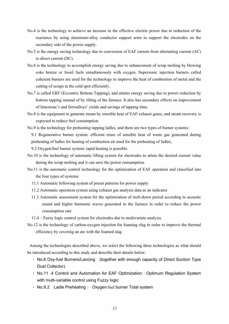
Figure 2.2-18 Presumed effect (power saving, CO2 reduction) of each technology from Technologies positive list
CO2Reductionkg-CO2/t
of productGJ/t
of productkWh/t
of product
1 Hot DRI/HBI Charging to the EAF 84.6 >150 ○
2 Scrap Preheating (ex. Ecological and Economical Arc Furnace) 84.6 150 1. reduction of DXN, Dust, Noise ○
3 Transformer efficiency—ultra-high power transformers 8.5 15 ○
4 Aluminium Alloy Conductor Arm for Supporting Electrode 1.6~3.3 3~6 *1
5 DC Electro Arc Furnace 5~10.1≦5%9~18
1.electrode consumption -(40-60)%2. reduction of flicker -(50-60)%, noise
○ ○
6 Oxy-fuel Burners/Lancing (together with enough capacity of direct suction type dust collector) 10.1~20.2 0.14 18~36 ○ ○
7 Eccentric Bottom Tapping (EBT) on existing furnace 3.9~1413.6
(7~25)1. 15-25% reduction of CaO(kg/t)2. shorter tap-to-tap times
○
8 Waste Heat Recovery from EAF 81.7 0.86 ○
9 Ladle Preheating9.1 -Regenerative Burner Total System 20.0 0.21 or 51% ○
9.2 -Oxygen/fuel Burner Total System ≧50% 1. life extension of refractory *2
10 Electrode Position Control for Power Optimization 10.4~16.9 0.11 301. electrode consumption -25%2. Productivity: +(9-12)%
○ ○
11 Control and Automation for EAF Optimization11.1 - by pattern presetting11.2 - by using Off-gas Analysis 19.7 35 ○ ○ *3
11.3 - Automatic Scrap Meltdown Timing Judgment System by Acoustic Spectrum Analysis for AC EAF 1.6~3.3 3-6 1. skill free *4
11.4 - Optimum Regulation System with multi-variable control using Fuzzy logic 10 *6
12 Carbon and Oxygen Injection System for foamy slag practice 2.8~3.90.04~0.05or 2.5~3%
5~7 ○ ○
13 Combustion Air Preheating for reheating furnace
13.1 - Preheating temperature ≧1000℃ by Regenerative Burner Total System 16.1~19.945%(S),
0.17-0.21(N)1. reduction of NOx ○ ○ ○
13.2 - Preheating temperature 600℃ by Recuperator using high heat resistance steel 10.7~13.3 30% ○
13.3 - Preheating temperature 400℃ by Recuperator 7.1~8.820% (S)0.7(E)
○ ○
14 Thermal insulation by Ceramic Fiber on inner wall of reheating furnace 15.2 2-5%, 0.16 ○ ○
15 Process Control for Reheating Furnace 19.9~79.8 0.21~0.84 ○
16 Air Conditioning by Hot Water Absorption Chiller utilizing Waste Heat 1.5 2.6 *5
17 Inverter (VVVF; Variable Voltage Variable Frequency) Drive for Motors 42% ○ ○ ○ ○
18 Energy Monitoring and Management Systems for Steel Plant with EAF 0.5% ○ ○ ○
Remarks;*1:*2:*3: Iron Steel Technol Conf Proc, vol.1, 2006, pp.509-518*4: Daido Steel*5:*6: NIKKO Industry CO.,LTD
estimated by JFE Techno-Research Corp. from data supplied from EBARA Refri. Equip. & Systems Co., Ltd.
CHUGAI RO Industry CO.,LTD, and http://www.klchem.co.jp/blog/2013/08/post_2094.phpNIKKO Industry CO.,LTD, and "Tekko-Binran" (Handbook of Iron and Steel) Vol.5, No.6, p.224
Miscellaneous
SO
AC
T
Indi
a T
CL
ver
.2No. Title of Technology
Technologies Reference
Mis
cell
aneo
us
Steelmaking
Reheating Furnace
Effect of Technologies IntroductionEnergy Savings
(Fuel)Co-benefits
EP
A-B
AC
T
NE
DO
EU
-BA
T

25
3. THE REVIEWS ON THE SPECIFIC PROJECT PLANNING FOR
COMMERCIALIZATION
Upon commencement of the field surveys, we requested the government of Vietnam (Heavy
Industry Dept., Ministry of Industry and Trade (hereinafter referred to as MOIT) to select the
steelworks which are willing to accept the study of the project on energy diagnosis and technology
introduction to EAF mills in Vietnam, and two companies were the candidates. Both of the companies
desired to receive energy diagnosis and study of the project, and we finally determined field surveys
on both of the companies. Hereinafter, the companies are referred to as A-Company and B-Company,
respectively.
These 2 companies locate in the north area in Vietnam. One is a steelworks with its long history, the
other is a comparatively new one which was established after 2000, and then they are contrast
steelworks to each other.
In surveying both the companies, we implemented field surveys and presentations according to the
schedule below:
1st visit (Sep. 2014), Preliminary field surveys on both EAF steelworks
Contents: Presentation of the project purpose (including introduction of JCM scheme),
Understanding of the actual conditions (plant tours and operation observations)
Discussion of the issues on energy, and refinement of applicable technology
2nd visit (Nov. 2014), Technical study of both EAF steelworks
Contents: Energy diagnoses of the electric furnaces and the RHF
Diagnoses of each of the processes on energy saving, and study of feasibilities of the
technology
Collection and estimation of data to evaluate energy saving
3rd Visit (Jan. 2015): Seminar
Presentation of the diagnosis results, the estimation of profitability for each technology,
and explanation of JCM
As for both of the EAF steelworks in Vietnam, we refined the equipment and the technology
applicable to them through actual condition surveys on the steelworks, and discussions with the
officers of the steelworks during our 1st visit. During the 2nd visit, we practically implemented
surveys and diagnoses, and during the 3rd visit, we held a seminar to present the results from the
surveys and the diagnoses and to focus on the profitability of the application of the technologies.
During the 2nd visit and diagnosis, we were accompanied by people from engineering firms
specializing in EAFs and RHFs in iron and steel making process, they also implemented diagnosis
and study based on applicability of the technologies to estimate the cost for the applicable
technologies and to do trial calculations of the merits together with us.

26
During the 1st and 2nd visits, we also explained to the relevant ministries and agencies to JCM in
Vietnam, the contents and activities of the project, and the details of JCM, which will be described
late in Chapter 5.
The contents of these three times of visits are described below.

27
3.1 THE REVIEW ON THE SPECIFIC PROJECT PLANNING FOR A-COMPANY
To A-Company, the 1st and 2nd visits were made by the members and on the schedule shown in Fig.
3.1-1.
Figure 3.1-1 Visit to A-Company
Period Delegation member
1st visit Sep. 11th to 12th ,2014
11th : Explanation of outline of this
project and Fact findings of EAF and
RHF
12th : Fact findings of iron making
process and discussion
JFE Techno-Research:2
JFE Steel:2
2nd visit Nov. 17th to 19th ,2014
Study and diagnosis for targeted
technologies application
JFE Techno-Research:2
JFE Steel:2
EAF Engineering maker:2
RHF Engineering maker:2
3rd visit Jan. 20th ,2015
Reporting the result at Seminar in Hanoi
JFE Techno-Research:2
JFE Steel:1
3.1.1 OVERVIEW OF A-COMPANY
Figure 3.1-2 shows an overview of A-Company steelworks.
Figure 3.1-2 Overview of the steel plant
No.2 EAFCapacity: 45ton/heatproduction
:300,000ton/y
Main Facilities
Reheating FurnaceNo.2 RHF
Capacity: 50ton/h
No.1 EAFCapacity: 20ton/heatproduction
:150,000ton/y
Reheating FurnaceNo.1 RHF
Capacity: 30ton/h
Blast Furnaces, Sintering Plant, Cokes ovens
BFSinterCoke Making

28
A-Company is a steelworks holding blast furnaces and coke ovens along the river, and behind them
an extensive site on which sintering furnaces and an electric furnace plant stand.
Its steelmaking process is an electric furnace one, and both scraps and hot metal from the blast
furnace are its iron sources. There are two units of EAFs as steelmaking equipment and two lines of
RHF and a rolling machine as rolling equipment in the plant, and the steelworks holds coke ovens,
sintering furnaces and blast furnaces in its upstream process. The steelworks is characterized by its
operation at the EAFs, where about a half of the iron source is hot metal from the blast furnaces and
the remainder relies on scraps.
The steelmaking plant holds two units of EAFs, the large scale No.2 EAF mainly produces molten
steel. Both of them are made in Chine and considerably old facilities.
Molten steel is treated at a ladle furnace (LF) and it is cast at a 4-strand continuous casting machine.
The cast products are transferred into RHF. There are two units of RHFs, one is the old and
Chinese-made No.1 RHF, and the other is the No.2 RHF which commenced operation in 1996.
A-Company intends that billets are supplied to No.2 RHF by hot charging from the steelmaking plant.
About 80 - 85% of the billets are supplied to the RHF at a temperature of 500 - 600℃, and the hot
charging is put into good practice (hot charging is not in operation at No.1 RHF).
Oil (Fuel Oil, F.O) is used as a fuel for both of No.1 and No.2 RHFs, however, we could not confirm
any information on type and property of the oil. No.1 RHF is a Chinese-made and old facility;
nevertheless, it is maintained sufficiently and kept in good condition. No.2 RHF is also kept up in
good condition.
This rolling process produces steel bars as finished products, which are shipped.
Meanwhile, the steelworks plans on expanding its annual production to about 1 million tons per year
in the future. The steelworks currently holds two blast furnaces, and a new blast furnace is under
construction. In line with this, the steelworks plans to construct a steelmaking plant as well as a
sintering plant and a coke oven. In addition, construction of new RHF is almost completed. It seems
that the steelworks enters a period of transition to some kind of integrated steelworks.
We describe the overviews of the EAF and the RHF below.
The following are the typical indices of operation for No.2 EAF and No.2 RHF which are finally
chosen as the facility subject to the study. The values below rely on the documents of A-Company
and the interviews with the officers.
EAF
・ Average tapping quantity: About 45 t-steel/heat
・ Average power consumption rate: 250 kwh/t-steel
・ Average oxygen consumption rate: 55 m3N/t-steel
・ Average coal consumption rate: 10 kg/t-steel
Much usage of hot metal gives the facility a feature that the power consumption is lower and the
oxygen usage is more than those of an average EAF.
RHF

29
・ RHF capacity: 50 ton/h (walking hearth type)
・ Hot charging ratio: 80 – 85% (at an assumed temperature of 500 – 600℃)
・ Fuel: Oil (details unknown)
・ Fuel consumption rate: 24 l/t-steel (210,000 kcal/t-steel, when hot charged)
31 l/t-steel (273,000 kcal/t-steel, when cold charged)
Where the energy conversion factor is assumed as 8,800 kcal/l, supposing that Oil is fuel oil
A (JIS K2205 Class).
・ Furnace temperature: 1150℃
It is a very conventional RHF, however, the fuel consumption rate is lower compared to an average
RHF because of its intention of hot charging.
3.1.2 SPECIFICATION OF ISSUES ON ENERGY SAVING TO STUDY
On the 1st visit, we presented the technology in Japan, took a tour of the whole steelworks, and had a
discussion focused on issues A-Company has with energy saving.
Figure 3.1-3 Meeting with A-Company at 1st visit
Based on the discussion with officials of A-Company and the current situations witnessed through
plant tour, following technologies are the issues for study of the technologies.
(1) Study of energy saving technologies for EAF:
oxygen lances, burners, coal injection, and reduction in electric power consumption rate by
application of the technologies such as the optimal control for an EAF.
(2) Study of fuel consumption reduction for RHF:
diagnosis of the current operation and reduction in fuel usage by introduction of the
regenerative burners.

30
(3) Utilization of gases in the whole steelworks:
gas balancing in the whole steelworks and effective utilization of B gas.
Based on the premise of study of the above items, we implemented surveys and study, and specified
technologies to introduce on the 2nd visit. The above item (3) is not likely linked to a practical project
at this moment. However, we considered it subject to the study because it is important to save energy
at the steelworks in future.
3.1.3 DIAGNOSIS ON ENERGY SAVING ISSUES AND ESTIMATION OF APPLICABLE
TECHNOLOGIES
As for the three items of issues as stated above, we implemented field study and diagnosis on the
2nd visit, accompanied by engineering makers specializing in EAFs and RHFs. In the field survey, we
observed operations at the plants, provided recommendations on improvement of the current
operations through observation of operations, and studied the optimal application of technologies. In
addition, the engineering firms studied the estimations and construction periods on the spot, and we
based them on our final estimation of economical evaluation.
We will describe the details on each of the technologies below.
(1) STUDY OF ENERGY SAVING TECHNOLOGIES FOR THE EAF:
On the study of technologies, we followed through such steps as witnessing the operation at the plant,
identifying issues, and studying appropriate technologies to introduce. We show the approximate
merits by introduction of the technologies below; nevertheless, further study in detail is required.
Figure 3.1-4 Photo of EAF under operation
① Observation of operation at the EAF plant
Figure 3.1-5 shows a result we obtained through the observation of an operation at the EAF.

31
Figure 3.1-5 operation observation of EAF at the site
Results of the observation are summarized as below:
・ Charging 10 tons of scraps (referred to as SC① in the figure), cutting the scraps with oxygen
for around 3 min, and charging 20 tons of hot metal (HM in the figure).
・ After that, raising the voltage to start scrap melting, and charging some scraps for the second
time at the point when the scraps were melted to some extent.
・ Subsequently, melting the scraps in the same way, and charging once more scraps for the third
time at the point when the scraps were melted to some extent.
・ After the third charging, blowing just oxygen (for about 16 min.), and entering the refining
period at the point when the scraps were thoroughly melted. Foaming slag by carbon injection,
and completing the refinement.
② Findings on the operation
The findings as described below are extracted through the observation of the operation.
Finding 1: As shown as “①Oxygen Supply” in Fig. 3.1-5, the operation period is elongated due to the
long period of oxygen supply without turning on the electric power.
Finding 2: As shown as “②Tap change” in Fig. 3.1-5, the electric power is temporarily turned off
every time the voltage is changed. Moreover, there is large fluctuations of electric current through
each of the electrodes (Figure 3.1-6), and high electric power can not be inputted stably, which leads
to the elongation of the operation period.
500
450
4001 2 3 4 5 6 7 8 9 10 11 12 13 14 15 16 17 18 19 20 21 22 23 24 25 26 27 28 29 30 31 32 33 34 35 36 37 38 39 40 41 42 43 44 45 46 47 48 49 50 51 52 53 54 55 56 57 58 59 60 61 62
442V
509V
442V
509V
442V428V
Time (min)
Tap V(V)
SC① 10t
HM 20t SC② 10tSC③ 5t
600 4511 7093 8244 10142Total (kWh)
Charge: SC 25t,HM 20t⇒Tap:42tPower consumption: 241kWh/tOxygen consumption:55Nm3/t
Oxygen
16minTap change Tap change Tap change
PON Tap
Cutting De-C Decarburization
Timing of Hot metal charge
②
①
Tap change
③
Oxygen supply

32
Figure 3.1-6 Current fluctuation of each electrode
Finding 3: As shown as "③Timing of Hot metal charge" in Fig. 3.1-5, hot metal is charged just after
charging of scraps, which may cause to solidify the charged hot metal.
Finding 4: As shown in Fig. 3.1-4, flames are blown out of the furnace throughout the whole period of
operation. This leads to the loss of energy, causes damage to the peripheral equipment, and worsens
the surrounding work environment.
Based on the above issues, we recommend the introduction of appropriate technologies.
③ Recommended improvement
The Finding 1, 4 require a common measure to solve.
As for the facility concerning the Finding 4, first we confirmed that the EAF is not equipped with
any precipitator called “Dust Collector” which is indicated in Fig. 3.1-7 by the eclipse in red and is
usually installed on EAF. Therefore, flammable materials generated in the furnace are all emitted out
of the furnace, and they are to be collected into the dust collector equipped onto the ceiling over the
top of the EAF.
Figure 3.1-7 Dust Collector of EAF
Consequently, the pressure is always positive in the furnace, such materials as gas and dust that are
generated in the furnace will be all emitted out of the furnace, and they are to react with the air to
Dustcollector
Suction
Slag Door

33
undergo combustion. In this case, there are the following points at issue:
・ Loss of energy is caused due to the combustion outside the furnace, of non-reacting materials in
the furnace.
・ Repairs cost will increase because of greater deterioration of the peripheral equipment such as a
furnace lid, electrode holders, and so on, due to the outside combustion.
・ Building dust collector can not sufficiently collect such materials as dust that is generated in the
furnace, which leads to worsening the surrounding environment.
Considering the above issues, we conclude that installation of the “Dust Collector” is the first and
direct measure to energy saving and environmental improvement.
Meanwhile, as for the Finding 1, because hot metal (usually including more than 4 % of carbon) is
used for the operation of the EAF, oxygen is required to lower the carbon content in the hot metal;
nevertheless, the sole source of oxygen supply is currently the oxygen from the oxygen lance which is
inserted through the slag opening. There is no “Dust Collector”, which causes the loss of energy; the
scrap melting rate is limited by the rate of oxygen supply and the power consumption rate will be
worsened by the elongation of operation period.
The measures to the above are as follows:、
・ Installing a “Dust Collector” with a sufficient capacity,
・ Progressing in promotion of scrap melting and positive supply of oxygen
As for the latter regarding oxygen supply, we can recommend application of the technology, “No.6
Oxy-fuel Burners/Lancing (in combination with direct-suction-type Dust Collector with
sufficient capacity)” in the Positive List. Furthermore, the energy efficiency can be more improved
by adoption of a door burner which is one of the associated technologies for the Oxy-fuel
Burners/Lancing technology.
Currently, oxygen is supplied into the melt in the EAF only by the lance at slag opening. By
installation of Oxy-fuel Burners/Lancing in combination with a door burner, it is possible to prevent
the furnace from infiltration of outside air and to supply oxygen efficiently. Therefore, the technology
can attain power saving and shorter operation time.
As mentioned above, we can recommend application of “Oxy-fuel Burner System + Introduction of
Direct Suction Type Dust Collector” technology to solve the Finding 1. In such a case, we expect that
the power consumption rate can be reduced by 25kwh/ ton-steel.
However, as stated above, an auxiliary fuel is required to use a burner. The auxiliary fuel can be
considered to rely on the C gas which is generated out of the coke ovens and is excessive in the
steelworks. As the steelmaking process utilizes hot metal, any burning function is required only at the
beginning of the scrap melting period, and therefore it requires an equivalent amount of an auxiliary
fuel to 5 Nm3/t-steel of natural gas. When C gas is used, the required amount is 11.1 Nm3/t-steel.
From the viewpoint of CO2 emissions reduction, if we can confirm that necessary and sufficient C
gas is currently emitted to the air for the EAF to require, there is no more cost of C gas and no more
emissions of CO2, however, the more study will be necessary to make it clear in future.
As for the Finding 2, it is necessary for the control system to improve. As a measure to it, we can

34
recommend application of “No.11 Control and Automation for EAF Optimization” in the
Technologies Positive List. Renewal of the control system enables us to change the voltage setting
without turning off the electric power. In addition, the new “Optimal Power Regulation System”
mentioned above enables us to efficiently input the electric power. The estimated power saving will
be 10 kWh/t-steel by adoption of these systems.
Finally, as for the Finding 3, it is the point at issue that hot metal is charged just after scraps are
charged and they are cut with an oxygen jet. As shown in Fig. 3.1-8 which is the iron carbon (Fe-C)
binary phase diagram, when hot metal includes about 4% of carbon, its solidification point is 1147℃.
When hot metal is charged into a furnace which has been already charged with scraps, the hot metal is
cooled by the scraps in the furnace and it may be solidified. Therefore, a desirable operation shall be
as follows: Charge scraps into the furnace. Melt the scraps. Bore the scraps. Charge hot metal into the
furnace after scrap is bored. By prevention of hot metal from solidifying in the furnace, it leads to
avoiding electrode breakage and hot metal splash.
Figure 3.1-8 Phase diagram for Fe and Carbon
④ Summary on recommended technologies
As stated above, we recommended the following technologies through witnessing the operation.
・ ”No.6 Oxy-fuel Burners/Lancing (in line with direct-suction-type Dust Collector with
sufficient capacity)”
・ “No.11 Automatic Control for EAF Optimization”
In addition, as for the EAF operation, we recommended improvement of the timing for hot metal
charging.
Figure 3.1-9 shows the expected effects by application of these recommended technologies.
Fe-C diagram
1147℃
[C] = 4%
Fe-C diagram
1147℃
[C] = 4%

35
Figure 3.1-9 Effect for proposed technologies to A-Company EAF
Items Effect
Electric Power
Saving
kWh/t-steel
Electric Power Saving
Oxy-fuel Burner System
+
Introduction of Direct
Suction Type Dust
Collector
Other merit
1. Increase of productivity
2. Saving of Operational expenses 15%
(Electricity / Electrode / Refractory /
Alloy / etc.)
3. Improvement of Environment & Safety
15
+
10
Electric Power Saving Electrode Regulation
and Automation Control
for EAF Optimization
Other merit
1. Increase of productivity
10
total 35
(2) STUDY OF FUEL CONSUMPTION REDUCTION FOR THE RHF:
On the study of technologies, we witnessed the operation at the plant, identified issues, diagnosed
the RHF and studied appropriate technologies to introduce. The observation was conducted only of
the No.2 RHF.
Figure 3.1-10 No2 RHF of A-Company
① Observation of operation at the No.2 RHF
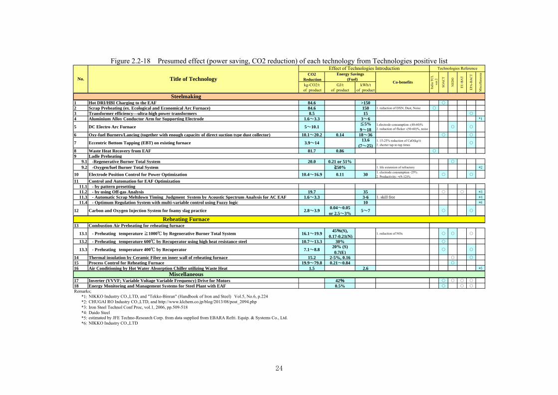
Figure 3.1-11 summarizes operational data of the No.2 RHF during the observation.
36
Figure 3.1-11 Operation condition at the observation
We found that some data are not indicated on the monitor as shown in Fig. 3.1-11. Troubles of
instruments were the main cause of this problem. We consider it important to promote operational
control by grasping the accurate values in future.
Hot charging was in practice during the observation, the furnace temperature averaged 1150℃ and
the production rate was 43 t-steel/h. We could not obtain the actual usage of “Oil” and the calorific
value of it, and then it was impossible for us to estimate the fuel consumption rate exactly.
As stated above, hot charging was conducted during the witness, which is of high value. The
charging billets were faintly lit, and the temperature was supposed to be 500 – 600℃. It seemed that
the furnace is well insulated and we can suppose that the furnace refractory is in good condition.
② Issues on the operation
On witnessing the operation, we were also requested to diagnose the temperature of preheated air
which is some 350℃ in spite of the specified value of 400℃. Therefore we conducted the study
taking it into account.
However, as noted above, there are a lot of inaccessible operational values. It is important to
organize these values (including maintenance of measuring equipment) and to control them in order
to promote operational control in future.
The following findings are identified through the observation of the furnace and its associated
equipment.
Finding 1: Inspection of the heat exchanger
Finding 2: Air fuel ratio (Air/Fuel) appropriate control
Finding 3: Furnace pressure appropriate control
However, these findings were checked just visually, and it is necessary to confirm and correct them
through inspections, and so on in future.
Hot charge operation on November 18,
Zone1(PHZ)
Zone2(HZ)
Zone3(SZ1)
Zone4(SZ2)
Zone temperature (degC) 1038 1131 1168 1168
Oil flow rate (L/h) ? ? ? 285
Air flow rate (m3N/h) 1009 984 893 935
Zone1(PHZ)
Zone2(HZ)
Zone3(SZ1)
Zone4(SZ2)
Zone temperature (degC) 1038 1131 1168 1168
Oil flow rate (L/h) ? ? ? 285
Air flow rate (m3N/h) 1009 984 893 935
Waste gas temperature (degC) 662
Hot air temperature (degC) 391
Furnace pressure (??) -0.28
Waste gas temperature (degC) 662
Hot air temperature (degC) 391
Furnace pressure (??) -0.28
Furnace condition
Material condition
Size (mm) 150 x 150 x 6000
Charging temperature (degC) 300
Size (mm) 150 x 150 x 6000
Charging temperature (degC) 300
Insulation goodInsulation good

37
Finding 4: Study of applying regenerative burners.
As for fuel reduction, we estimated introduction of ” No.13.1 – Integrated System for
Regenerative Burner at Preheating temperature ≧1000 ℃” in the Positive List, so-called
regenerative burners. However, we noted that it is necessary in installation of regenerative burners to
plan for revamping the facilities in consideration of utilizing surplus gas at the time of the capacity
extension in the future.
Summarizing the above issues, the Finding 1 to 3 is on improvement of the operations and the
Finding 4 is on study of new technology application.
③ Recommended improvement
As for the issue 1, we studied the heat exchangers focusing on insufficient preheating of air. There
was found such a point as shown in Fig. 3.1-12, and we proposed the necessity of inspection. First of
all, there is a possibility of waste gas leakage because we observed smoke emission from the top of
the heat exchanger. Second, the inlet temperature of the waste gas is low (suspicious of any leakage
of waste gas, and so on). Finally, it is necessary to check the leakage through bypass damper of
combustion air.
Figure 3.1-12 Combustion air Heat Exchanger
Figure 3.1-13 Improvement for Heat exchanger
As a measure to raise the temperature of reheated air from the standpoint of hardware, we
recommended revamping of the heat exchanger from the current parallel flow type into the cross flow
type, as shown in Fig. 3.1-13.
As for the Finding 2, we presumed that the air fuel ratio is not adjusted in accordance with the fuel
Fume from recuperator
Low waste gas temperature
Leakage inside ?
Leakage in duct ?
Bypass damper
Cold air mix with hot air?
Parallel flow type(Existing) Counter flow type

38
usage because we observed the condition of combustion in the furnace changing with the alternation
of furnace load during the operation. In addition, we also presumed it because the fuel usage is not
indicated. If the flow rate of air is excessive, the flow rate of waste gas increases and the heat loss of
waste gas increases. On the contrary, when it is deficient, incomplete combustion of fuel causes the
loss of energy.
As for the Finding 3, although the furnace pressure is indicated, it is not controlled at all. We also
observed blow off of gas out of and suction of it into the furnace. The blow off of gas leads to the loss
of heat, and the suction of it cools the furnace and also leads to the loss of energy.
Our recommendation on the Finding 1-3 is all the improvement of the current operation. First of all,
it is required to maintain measuring equipment (sensors) and preserve the control functions with
accurate measuring apparatus as premised. Moreover, as we recommended, measured result during
operation should be recorded accurately and managed exactly, and after that it is necessary to advance
to the step of building an energy management system in order to keep operation in normal condition.
As for the Finding 4 on introduction of regenerative burners, we recommended the two ways of
replacement of the burners, the full replacement and the partial replacement, considering the furnace
layout as shown below, operation, and so on, as well as from an economical point of view. Figure
3.1-14 illustrates a schematic drawing for partial replacement of burners.
Figure 3.1-14 planned diagram of partial burner replacement
The furnace currently consists of the preheating zone 1 (equipped with 2 burners), the heating zone 2
(with 4 burners) and soaking zones 3 & 4 (with 5 burners, respectively) (as indicated in blue in the
figure). The plan of partial burner replacement suggests that a total of 6 burners at the preheating zone
and the heating zone will be replaced by 2 pairs of regenerative burners (as indicated in red). At the
same time, the new burners will be increased in capacity. The soaking zone will be untouched. The
plan aims at enhancement of energy saving effects by supplying more fuel through large-sized
regenerative burners.
Figure 3.1-15 shows the comparison of effects obtained by the full replacement and the partial one.
Zone1 & 2burner : 2+4
Zone3 & 4Burner : 10
Existing burnerZone1 & 2Regenerative burner2pairs Zone3 and 4
Burner : 10(same as existing)
After modification

39
Figure 3.1-15 Comparison of effect for all burner replacement and partial burner replacement
Large effect will be obtained by the full replacement of burners because among the four zones, the
most burners are equipped in the soaking zone which will be also revamped in this case. However, the
investment cost will increase much more, and it is necessary to study the application considering its
profitability. In addition, there remains a room for more precise study of merits because we have
much lack of data for study.
Meanwhile, we studied gas balance associated with the capacity augmentation of A-Company in the
future.
When the expansion is completed, more by-product will be generated and some of the surplus gas
can be utilized as fuel in the RHF. “Oil” is currently used at the RHF, however, large energy saving
can be achieved by utilizing the surplus gas. We studied the gas balance in the whole steelworks and
the feasibility of surplus gas utilization to RHF. The result is described below.
④ Utilization of gases in the whole steelworks
On studying the gas balance, we obtained those data first. In addition, we also used various empirical
values for the estimation because we could not receive enough data on the generation or usage of
by-product gases in the steelworks.
Figure 3.1-16 shows the current gas balance and the future one after theaugmentation.
Figure 3.1-16 presumed results of present gas balance and future gas balance after augmentation
Each of the abscissas indicates from the left side, the generation of C gas from the coke ovens, the
consumption of C gas, the generation of B gas from the blast furnaces, the consumption of B gas, and
Case Energy saving ratio
Shut down period
A Replace all burnersZone 1 ~ 4
15.0% 4weeks
B Replace burners in Zone1 & 2
10.0% 3weeks
Case Energy saving ratio
Shut down period
A Replace all burnersZone 1 ~ 4
15.0% 4weeks
B Replace burners in Zone1 & 2
10.0% 3weeks
Present Condition (Gcal/y)
0
200,000
400,000
600,000
800,000
1,000,000
1,200,000
1,400,000
CO
G
Pro
duc
tion
CO
G
Con
sum
ptio
n
BF
G
Pro
duc
tion
BF
G
Con
sum
ptio
n
OIL
Con
sum
ptio
n
Expansion Condition (Gcal/y)
0
200,000
400,000
600,000
800,000
1,000,000
1,200,000
1,400,000
COG
Pro
duction
COG
Consu
mption
BFG
Pro
duction
BFG
Consu
mption
OIL
Consu
mption
Residual
Steam Boiler
Melting shop
Blast Furnace
Cokes Oven
Sinter
COG

40
the usage of Oil by the RHF at the right end. The figure on the left hand side shows the estimations of
the current gas balance, and the one on the right hand side shows those of the gas balance after the
augmentation.
In addition, Fig. 3.1-7 shows the property of B gas and C gas used for the above estimations.
Figure 3.1.-17 Gas property of B-gas and C-gas9
Production rate Composition and Calorific Value
Cokes Oven gas
(C-gas)
300~400
m3N/t-coal
H2;50~54%、CH4;30~33%
CO;6~8%,CmHn;2~4%
Calorific Value;4,500~5,000kcal/m3N
Blast Furnace gas
(B-gas)
約1,500
m3N/t-hot metal
CO;21~23%、CO2:19~22%,
H2 :2~3%、Residue:N2
Calorific Value;700~750kcal/m3N
B gas is considerably excessive at the current gas balance, while C gas is not very much excessive.
After the augmentation, the excess of B gas will be remarkably increased, and C gas will become
some excessive. The usage of Oil will be also increased due to the augmentation. It seems possible to
change the RHF fuel “Oil” to surplus gas because B gas is more excessive calorimetrically. However,
it will be impossible to operate the RHF only with B gas, because 2,000 to 2,500 kcal/Nm3 of the gas
is necessary for securing the furnace temperature and calorie of B gas is as low as around 750
kcal/m3N. Therefore, the RHF will require 2,000 to 2,500 kcal/m3N of M gas which is made by
mixing B gas with C gas. It is because C gas has a calorie of around 4,500 kcal/m3N. The calorie
content of C gas should be higher than 75% in M gas in order that the calorific value of M gas
becomes higher than 2,000 kcal/m3N. If the production is extended in the same condition as of now, it
is presumed possible to change a part of the furnace fuel, however difficult to change all of the
furnace fuel because the excess of C gas will not reach 75% of Oil usage by the RHF.
On the other hand, the steelworks holds the processes of an integrated steelworks including a blast
furnace and a coke oven; therefore, there is a room in such other facilities for introducing energy
saving equipment, which may bring out more C gas than planned augmentation.
Figure 3.1-18 shows typical energy saving technologies at an integrated steelworks.
9 World Encyclopedia 2nd edition

41
Figure 3.1-18 Major energy saving technologies for integrated steel plant
Figure 3.1-19 shows the future gas balance after the augmentation with the application of the
technologies which are relatively easy to introduce (as indicated in red letters within a red frame
together with its energy saving ratio) among these technologies.
Figure 3.1-19 Gas balance in the case of introducing some of the major energy saving
technologies to the steel plant
By introduction of the energy saving technologies, the excess of B gas will be increased and that of
C gas will be also increased. It will be possible to change all the RHF fuel into by-product gas (B gas,
C gas and in addition recovered gas from steel converter: LD gas) because the excess calorie of C gas
Improvement Condition (Gcal/y)
0
200,000
400,000
600,000
800,000
1,000,000
1,200,000
1,400,000
COG
Production
COG
Consumption
BFG
Production
BFG
Consumption
OIL
Consumption
LDG
Residual
Steam Boiler
Melting shop
Blast Furnace
Cokes Oven
Sinter
COG
BF
G +
LDG
BF
G +
LDG
・Off gas boiler•TRT
Energy: power station, utility supply
BFBF
Hot Stove •Combustion Control•Heat Exchanger
(Δ15%)
SinterSinter
Coke Making
・High efficiency ignition burner(Δ50%)
・Efficient power generation・Efficient air separator・Energy audit・Power saving
・Combustion Control(Δ15%)
BOFBOF
・BOF gas recoveryOG
Rolling mills
Furnace rolling
Rolling mills
Furnace rolling
・Regenerative burner
(Δ15%)
Coke OvenGas
Blast Furnace Gas
BOF Gas
By-product GasPower, Air, Steam, etc.
PowerSteam
Power・Slag
・CDQ
・Product cooler heat recovery
:Considered technologies
: other energy saving technologies

42
will become almost 75% of Oil calorie. Introduction of energy saving facilities leads to increase in the
excess of by-product gas and it becomes possible to exclude “Oil” from the RHF due to conversion of
all the RHF fuel into by-product gas. This fuel conversion is considered to be the most efficient in
energy saving. Moreover, if a power facility is installed and it generates electric power using an
excess of by-product (including LD gas in the figure) after the fuel conversion of the RHF, the more
energy saving can be attained. A power facility with the generation efficiency of 30% will enable to
produce the power of 230 GWh/y.
As described above, the promotion of energy saving in the whole steelworks can achieve the fuel
conversion of “Oil” into surplus gas at the RHF(s). As far as installation of regenerative burners is
concerned, we presume that energy saving can be more efficiently attained due to avoiding duplicate
investment by simultaneous installation of regenerative burners at the time of the fuel conversion into
surplus gas.
⑤ Summary on recommended technologies
We recommended the following regarding the RHF.
・ Inspection and maintenance of heat exchanger,
・ Proper control of combustion and furnace pressure by restoring and normalizing measuring
equipment and controller,
・ Reduction of energy consumption by installation of regenerative burners.
Among them, we picked out regenerative burner “No.13.1 – Integrated System for Regenerative
Burner at Preheating temperature ≧1000 ℃” for the technology subject to the project study.
As for the installation of regenerative burners,
・ Study of the two ways of replacement, one is the full replacement which means that all the
existing burners are replaced into regenerative burners, and the other is the partial replacement
which means that not all but a part of the existing burners are replaced into regenerative burners,
・ Study of the future balance of surplus gas at the time of planned augmentation of A-Company,
and the fuel conversion of “Oil” of the RHF into by-product gas.
As for the latter regarding the fuel conversion, we presumed that it will be possible to change all the
RHF fuel “Oil” into surplus gas due to its excessive generation by introduction of appropriate
technologies to the currently existing facilities and/or the future planned facilities.
Although the fuel conversion of RHF will have a larger effect on energy saving, we recommended
the application of regenerative burners to the current RHF using “Oil” as fuel in this study.

43
3.2 THE REVIEW ON THE SPECIFIC PROJECT PLANNING FOR B-COMPANY
To B-Company, the 1st and 2nd visits were made by the members and on the schedule shown in
Figure 3.2-1.
Figure 3.2-1 Visit to B-Company
Period Delegation Member
1st visit Sep. 9th to 10th ,2014
9th : Explanation of outline of this project
and Fact findings of RHF
1oth : Explanation of outline of this project
and Fact findings EAF
JFE Techno-Research:2
JFE Steel:2
2nd visit Nov. 20th to 22th ,2014
Study and diagnosis for targeted
technologies application
JFE Techno-Research:2
JFE Steel:2
EAF Engineering maker:2
RHF Engineering maker:2
3rd visit Jan. 20th ,2015
Reporting the result at Seminar in Hanoi
JFE Techno-Research:2
JFE Steel:1
3.2.1 OVERVIEW OF B-COMPANY
Figure 3.2-2 shows the overview of B-Company steel plant.
Figure 3.2-2 Overview of B-Company
Main Facilities
Reheating FurnaceCapacity: 50ton/h250,000ton/y
Electric Arc Furnace⇒ Consteel® SystemCapacity: 70ton/heat, 400,000ton/y

44
B-Company is the typical steelworks with EAF. B-Company possesses 1 EAF and 1 RHF, and EAF
operates with 100% scrap as a raw material. The capacity of EAF exceeds that of RHF, and
operations are matched with RHF capacity. The special feature of this steel company is that EAF and
RHF are far by car for approximately 2 hours, and the transportation of billets must rely on land
transportation.
We describe the overviews of the EAF, Ladle preheater, and RHF which become the focus of this
study. These values below rely on the documents of B-Company and the interviews with the officers.
EAF:
・ Type of scrap charging system: Consteel®10 type
・ Tapping weight: approximately 70 t-steel
・ Specific power consumption: 345 kwh/ t-steel
・ Specific oxygen consumption: 39 m3N/ t-steel
・ Specific coal consumption: 24 kg/t-steel
This EAF has the special scrap charging system, so called Consteel®. Consteel® feeds scrap
continually from the side wall of the furnace, and at the same time as the waste gas from EAF passes
through the scarp passage, scrap is preheated before charging to the furnace. The power consumption
of EAF is comparatively low because of this continuous feeding and preheating of scrap. The oxygen
consumption is reasonable but the coal consumption is relatively high.
Ladle Preheater
・ Preheater:Vertical type ladle preheater: 2sets, Horizontal type ladle preheater: 2sets
・ Fuel; Coal gasification gas from coal gasification plant
・ Specific fuel consumption: 7 kg-Coal/t-steel(360kg/h)
・ Average preheating time: 40~50 minutes
This ladle preheater has the special feature that it uses coal gasification gas from coal gasification
plant.
RHF:
・ Heating Capacity: 50 t-steel/h (Walking hearth type)
・ Hot charge ratio: 0% (all cold charge)
・ Fuel: coal gasification gas from coal gasification plant
・ Fuel consumption rate: 71 kg-coal/t-steel
・ Furnace temperature: 1,170 deg.C
This RHF is the typical type furnace except that it uses coal as a fuel. This RHF used oil as a fuel
previously, but converted to coal from economical reason.
3.2.2 SPECIFICATION OF ISSUES ON ENERGY SAVING TO STUDY
On the 1st visit, we presented the technology in Japan. After plan tour, and had a discussion focused
10 http://www.tenovagroup.com/consteel_system.php?id_prodotto=8

45
on issues B-Company has with energy saving. Because B-Company has EAF and RHF at different
place, meetings were held at each plant.
Figure 3.2-3 Meeting at 2nd visit
Visit to EAF plant
Based on the discussion with officials of B-Company and the current situations witnessed through
plant tour, following technologies are the issues for study of the technologies.
(1) Study of Energy saving technologies for EAF
Operation diagnosis for EAF and study about oxygen lance, burners, coal injection, optimum
control for EAF
(2) Study of Improvement of Ladle Preheater
Application of high efficiency of oxy-fuel burner to ladle preheater
These items were main study issues of 2nd visit, and through operational observation and study,
candidates of projects were identified.
Visit to RHF plant
(3) Diagnosis of present operation of RHF, study of fuel saving, and feasible study of capacity
improvements for RHF. (The capability of this RHF does not reach its specified value.)
(1) STUDY OF ENERGY SAVING TECHNOLOGIES FOR EAF
On 2nd visit, we followed the same step as A-Company after witnessing the operation and identifying
issues, and studying appropriate technologies to introduce.

46
Figure 3.2-4 Site view of EAF
① Observation of operation at the EAF plant
Fig. 3.2-5 shows a result we obtained through the observation of an operation at the EAF.
Figure 3.2-5 operation observation of EAF at the site
The operation of this observation was as follows.
・ Holding 18 tons of molten steel from previous operation in the furnace, the operation started
with continuous scrap feeding.
・ After 10 minutes operation, EAF opened furnace lid, and big scrap was charged from the lid.
・ Restarted the operation and scrap was continuously fed to the furnace.
・ After 30 minutes operation, carbon injection from slag opening started in order to foam slag,
and slag flowed out through the slag opening.
・ After 50 minutes operation, operation moved into the refining stage. Within 10 minutes, molten
steel was raised to the prescribed temperature and then tapped.
② Findings on the operation
The following Operation findings were captured through observation.
Current (kA)
Power (MW)30 20~28 (Unstable)~30 20~35 25~35 30~35
25~30 25~30 20~30 26~30 30~32 30~32
30 20~28 (Unstable)~30 20~35 25~35 30~35
25~30 25~30 20~30 26~30 30~32 30~32
Oxygen lanceCarbon-Inj
Tapping3200~3300Nm3/hr
Tap
V(V
)
400 10 20 30 50 60
20
600
700
0
40
60
80
100
Scr
ap C
harg
e
(t)
630V
44.1
55.6
70.6
82.494
40.0
33.0
18.3
630V
Scrap Charge7ton Scrap Charge total
(t)
1565℃
Slag off
1575℃
Oxygen lanceCarbon-Inj
Tapping3200~3300Nm3/hrOxygen lanceCarbon-Inj
Tapping3200~3300Nm3/hr
Tap
V(V
)
400 10 20 30 50 60
20
600
700
0
40
60
80
100
Scr
ap C
harg
e
(t)
630V
44.1
55.6
70.6
82.494
40.0
33.0
18.3
630V
Scrap Charge7ton Scrap Charge total
(t)
1565℃
Slag off
1575℃
Tap
V(V
)
400 10 20 30 50 60
20
600
700
0
40
60
80
100
Scr
ap C
harg
e
(t)
Tap
V(V
)
400 10 20 30 50 60
20
600
700
0
40
60
80
100
Scr
ap C
harg
e
(t)
Tap
V(V
)
400 10 20 30 50 60
20
600
700
0
40
60
80
100
Scr
ap C
harg
e
(t)
630V
44.1
55.6
70.6
82.494
40.0
33.0
18.3
630V
Scrap Charge7ton Scrap Charge total
(t)
1565℃
Slag off
1575℃
(min)

47
Finding 1: Fig 3.2-6 shows the current fluctuation of each electrode 10 minutes after operation started.
(The graph starts at this timing which corresponds to 0 second). The current fluctuation of No.1
electrode is the biggest, and that of No.3 is the most stable. 30 minutes after operation started (1200
seconds in graph), current fluctuation of all electrodes becomes stable. This imbalance of electrode is
one finding.
Figure 3.2-6 Current fluctuation from 10 minibus afar power on
Finding 2: Fig 3.2-6 indicates that current fluctuations of all electrodes are big. This big current
fluctuation may lead to low power input efficiency.
③ Recommended improvement
The current imbalance of Finding 1 is caused by the following phenomenon. The situation in the
furnace is presumed in Figure 3.2-7 from the understanding of Figure 3.2-6.
Figure 3.2-7 presumed furnace inside condition
#1,#2 fluctuate ,#3 stable
Unstable arc current
(A)
(second)
EBT
Scrap
Molten Steel Circulation
# 1(A) #2(B) #3(C)
Carbon InjectionOxygen lance

48
Scrap is fed from the right side of this Figure. Because of that, non-melted scrap remains at the right
side of the furnace. Non melted scrap causes the high current fluctuation of No.1 and No.3 electrode.
Meanwhile, Carbon injection is supplied from the slag opening in order to foam slag. However,
foamed slag instantaneously flows out through the slag opening. AS slag flows out of the furnace
soon, it is hard for the foaming slag to cover all inside the furnace, which explains the high carbon
consumption rate.
According to this presumption, the followings are proposed as shown in Figure 3.2-8
Figure 3.2-8 proposed technology to the current imbalance among each electrode
Installment of oxy-fuel burner at the back side of No.1 and No.3 electrode eliminates the non-melted
scrap. Installment of carbon injection near No.1 electrode can easily cover all inside the furnace than
the present position with smaller amount of coal injection. Both improvements reduce the electric
power consumption of EAF. Further improvement is expected by installing door burner, which melts
the scrap more efficiently. As stated above, “No.6 Oxy-fuel Burners/Lancing (together with
enough capacity of Direct Suction Type Dust Collector) “ in the positive list, and application of
door burner associated with the technology of Oxy-fuel Burners/Lancing, enables more energy
efficient operation. Application of this technology improves the electric power consumption by 20
kwh/t-steel. At the same time, carbon injection consumption is saved to 10 kg/t-steel. In order to
apply this technology, auxiliary fuels are required, and this plant must procure fuels from outside. Oil
or coal is the candidate, but coal is hard to ignite, so Oil is the 1st priority.
As for the Finding 2, “No.11 Control and Automation for EAF Optimization” in the positive list is
proposed. Introduction of new Optimum Power Regulation System enables efficient power input and
reduces the electric power consumption rate by 10 kwh/ t-steel.
④ Summary on recommended technologies
The following technologies are recommended through witnessing the operation.
・ “No.6 Oxy-fuel Burners/Lancing (together with enough capacity of Direct Suction Type
Dust Collector) “
Oxygen lance
Carbon Injection
Carbon Injection
Burner and Carbon Injection
Oxy-fuel burner
Burner and Carbon Injection
Non-melted scrap
Molten steel Circulation

49
・ “No.11 Control and Automation for EAF Optimization”
Figure 3.2-9 describes the effect of each proposal.
Figure 3.2-9 Effect of proposed technologies to B-Company EAF
Items Effect
Electric Power
Saving
kWh/t-steel
Electric Power Saving Introduction of Oxy-fuel
Burner System
& Multi Point Injection
System
Other merit
1. Saving Power on time (△5min)
2. Yield up by 1%
20
Electric Power Saving Electrode Regulation and
Automation Control for EAF
Optimization
Other merit
1. Saving Power on time (△ 3 min)
10
total 30
(2) STUDY OF FUEL CONSUMPTION REDUCTION FOR LADLE FURNACE
Figure 3.2-10 shows the diagram of the supply of fuel from gasification plant to ladle preheater. Coal
gasification gas from gasification plant preheats the ladles.
Figure 3.2-10 Schematic diagram of fuel supply to ladle preheater
① Observation of operation
Gasification plant is the coal bed type. Air is fed from lower part of the plant, combusts coal partially,
and the plant produces gasification gas. Feeding air is controlled according to the demand of fuel gas,
and at the same time coal is fed into the plant to keep the outlet gas temperature at 300 deg.C. The
calorific value of the gas is approximately 1,300 kcal/m3N, and is supplied to ladle preheater without
any cooling of the gas.
The preheating time of ladle is determined by the time cycle of ladles. Figure 3.2-11 shows this time
Coal Gasification Gas

50
cycle.
Figure 3.2-11 Time schedule of ladle
Ladles must stay at continuous casting (CC) during its operation, because CC is casting the molten
metal. This time cycle generates 40~50 minutes of waiting time from the relation between the timing
required for EAF and the time required for CC. During this waiting time, ladle preheater works for the
purpose of minimizing the temperature drop of molten steel from EAF to CC.
② Findings of operation
Present ladle inside temperature after preheating is approximately 800 deg.C. Calorific value of coal
gasification gas is relatively low of 1,300 kcal/m3N. This low calorie gas cannot give the high
temperature flame, which hampers the high temperature preheating of the ladle.
③ Recommended improvement
“No.9.2 Ladle Preheating: Oxygen burner Total system” in the positive list provides the higher
flame temperature, and realizes high temperature preheating of the ladle.
On the other hand, there is a possibility to improve energy saving in another way. Figure 3.3-11
explains the reason why the 40~50 minutes of waiting time generates. Another method of energy
saving is achieved by shortening the EAF operation time. If the operation time of EAF became
enough shorter than the current condition, the number of the ladle would decrease from 3 to 2 shown
in Figure 3.2- 12. In this case, there will be little waiting time.
Figure 3.2-12 Time schedule of ladle at the time of saving EAF operation time
In this case ladles can receive molten steel just after they leave CC. No preheating of ladles is
required because there is little time for the ladles to wait.
This measurement is not proposed here because it requires other improvements. However from the
energy saving point of view, this time schedule must be always considered.
EAF
LF
CC
Pre-heater
1hr
Ladle#1
Ladle#2
Ladle#3
If EAF time is reduced… EAF
LF
CC
Pre-heater
1hr
Ladle#1
Ladle#2
Ladle#3

51
④ Summary on recommended technologies
The followings are proposed according to the study above.
Figure 3.2-13 describes the study results.
Figure 3.2-13 Effect of proposed technologies to B-Company Ladle preheater
This technology saves fuel consumption by approximately 50%. Although this technology requires
oxygen, B-Company has oxygen plant in its site. It enables to provide cheaper oxygen, which makes
this technology more feasible.
(3) STUDY OF FUEL CONSUMPTION REDUCTION FOR RHF
RHF of B-Company uses coal gasification gas as a fuel shown in Figure 3.2-14. The principle of
coal gasification is the same as that of ladle preheater. However the size of the gasification plant is
much larger because of the amount of the energy consumed. Figure 3.2-15 shows the process of
gasification. This process produces coal gasification gas by feeding air and combusting coal partially,
cooling the gas, increasing the pressure, separating drain, and then this gas is supplied to RHF. The
gas produced has the calorific value of 1,350kcal/m3N.
Figure 3.2-14 Schematic diagram of fuel supply to RHF
Figure 3.2-15 Coal gasification process
Coal Gasification
plant
CoolingpressureIncrease To RHF
Original burner
O2 burner
Burner capacity 2250Mcal/h →45~55% down
1000Mcal/h
Fuel consumption 7.0kg/ton 3.5kg/ton
Coal Gasification gas (80~100%O2) 1890m3/h 840m3/h
Supplied O2(80~100%) volume *1 Nothing 200~250m3/h
Reheating FurnaceCapacity: 50ton/h250,000ton/yCoal Gasification
Gas

52
Through operation observation at the site, applicable technologies were studied and specifying
operation findings
① Observation of operation
Figure 3.2-16 summarizes the operation condition at observation.
Figure 3.2-16 Operation condition at the observation
We found that some data are not indicated on the monitor as shown in Fig. 3.2-16. Troubles of
instruments were the main cause of this problem. We consider it important to promote operational
control by grasping the accurate values in future.
At observation, RHF operated at furnace temperature of 1,168 deg.C, and at 50 t-steel/h. Specific
fuel consumption was not clear at this moment because of the uncertainness of coal and gas
consumption
② Issues on the operation
There are many uncertainness of the operation condition, it is recommended to maintain the
instruments and manage these values.
Through this observation, the following findings appeared.
Finding 1: Inspection of the thermometer of heat exchanger
Finding 2: Air fuel ratio (Air/Fuel) appropriate control
Finding 3: Furnace pressure appropriate control
These findings include presumption, and check and correction will be necessary
Finding 4: Study of applying regenerative burners
“No.13-1 Preheating temperature ≧1000℃ by Regenerative Burner Total System” in
positive list is effective for the energy saving and restoration of furnace capability, so this technology
was studied.
③ Proposals for improvement
Production on November 20,2014
Zone1 Zone2 Zone3 Zone4
Zone temperature (℃) 1031 1031 1168 1168
Gas flow rate (m3N/h) ? ? ? ?
Air flow rate (m3N/h) 5750 11500 ? ?
Zone1 Zone2 Zone3 Zone4
Zone temperature (℃) 1031 1031 1168 1168
Gas flow rate (m3N/h) ? ? ? ?
Air flow rate (m3N/h) 5750 11500 ? ?
Waste gas temperature (℃) Inlet 845
Waste gas temperature (℃) outlet 389(?)
Hot air temperature (℃) 553(?)
Furnace pressure (mmH2O) 1.72
Waste gas temperature (℃) Inlet 845
Waste gas temperature (℃) outlet 389(?)
Hot air temperature (℃) 553(?)
Furnace pressure (mmH2O) 1.72
Furnace condition
Material conditionSize (mm) 130 x 130 x 12000
Charging temperature (℃) 20
Production rate (t/h) 50
Size (mm) 130 x 130 x 12000
Charging temperature (℃) 20
Production rate (t/h) 50

53
Finding 1 is related to the temperature measurement of the heat exchanger. In figure 3.2-16.
pre-heated air temperature indicated higher value than that of waste gas outlet temperature. It was
hard to believe considering that the heat exchanger is parallel-flow type. And to convert the heat
exchanger from parallel flow type to counter flow type was also proposed as same as that of
A-Company.
Finding 2 suggested that combustion condition inside the furnace was altering according to the load
change by visual observation. Air/Fuel ratio control was not executed because of non gas flow
measurements. We recommend the same countermeasures as A-Company.
Finding 3 suggests that furnace pressure was basically positive, but there was no indication of
furnace pressure and no furnace pressure control. The effect of Finding 3 is the same as that of
A-Company.
Findings 1~3 are the proposals to operation improvement. We recommended the same
countermeasures as A-Company too.
Finding 4 studied the installment of regenerative burner system. we recommended the two ways of
replacement of the burners, the full replacement and the partial replacement as same as in the case of
A-Company. This RHF is almost same as that of A-Company except that the fuel is coal gasification
gas. Figure 3.2-17 shows the plan about regenerative burner system with partial burners’ replacement,
and this is same as that of A-Company.
Figure 3.2-17 planned diagram of partial burner replacement
Figure 3.2-18 describes this effect. These values are also the same as A-Company.
Zone1 & 2burner : 2+4
Zone3 & 4Burner : 10
Existing burnerZone1 & 2Regenerative burner2pairs Zone3 and 4
Burner : 10(same as existing)
After modification

54
Figure 3.2-18 Comparison of effect for all burner replacement and partial burner replacement
Energy saving rate of all burners’ replacement is bigger, but the investment becomes much bigger
because this replacement includes zone 3 & 4 which possesses many burners. On the other hand, the
investment of partial burners’ replacement is lower although the energy saving rate is low. The
selection depends on economical situation. However, more precise study is desirable in order to
clarify energy saving effect.
To the problem that the furnace capacity does not reach its specification, enlargement of burner
capacity is required. Another cause of this problem is the low calorific value of the gas which is
approximately 1,350kcal/m3N. This low calorific value gas may hamper the increase of furnace
temperature. Because regenerative burner system recovers high temperature combustion air, it
increases the furnace temperature, and at the same time it enlarges the burner capacity.
④ Summary on recommended technologies
Proposals for RHF are
・ Recommendation for check of thermometer of heat exchanger
・ Proper control of combustion and furnace pressure by restoring and normalizing measuring
equipment and controller,
・ Reduction of energy consumption by installation of regenerative burners.
“No.13-1 Preheating temperature ≧1000℃ by Regenerative Burner Total System” is the
candidate of the JCM project.
Both regenerative burner system with all burners’ replacement and partial burners’ replacement
are studied. This technology has not only energy saving effect but also restoration of furnace
capability, which is expected to contribute operation improvement.
Case Energy saving ratio
Shut down period
A Replace all burnersZone 1 ~ 4
15% 4weeks
B Replace burners in Zone1 & 2
10% 3weeks

55
3.3 ESTIMATION OF ENERGY SAVING AND CO2 REDUCTION RATE, AND
ECONOMICAL EVALUATION
Energy Saving rate and CO2 Reduction rate of each Technology are estimated, and at the same time
each technology is economically evaluated. Engineering makers cooperated together to estimate the
investment and merit of each technology.
Figure 2.2-1 describes the premise condition for economical evaluation. In Vietnam, deprecation
period of facilities is generally 10 years, interest rate from city banks are 10%, and their loan period is
6 years. VAT is 10%, which assumes to apply only for domestic procurement.
CO2 Emission Factor is shown again in Fig. 3.3-2 as mentioned before.
Figure 3.3-1 Conditions for economical evaluation
Estimated condition
Depreciation period 10years
Remaining book value 10%
Interest rate 10.0 %
Depreciation method Fixed Installment
Budget Loan from the bank
Loan period 6 years
Maintenance Expense 3 % of initial investment /year
Depreciation period 10years
Figure 3.3-2 CO2 Emission Factor
Conversion factor
CO2 Coefficient for Electric Power 0.564 t-CO2/MWh
CO2 Coefficient for Fuel Energy 5.9GJ-CO2/MWh
3.3.1 ESTIMATION OF ENERGY SAVING AND CO2 REDUCTION RATE, AND
ECONOMICAL EVALUATION FOR A-COMPANY
The following 4 technologies are studied.
Technologies for EAF
1. Direct Suction Dust Collector & Installment of Oxy-fuel burner system
Introduction of Oxy-fuel burner system with direct suction collector
2. Electrode Regulation and Automation Control for EAF Optimization
Introduction of new electrode Regulation system for EAF
Technologies for RHF
3. Regenerative Burner Total System :Replacement of all burners
4. Regenerative Burner Total System :Replacement of partial burners

56
Regenerative Burner Total System with either replacement of all burners or replacement of
partial burners
Fig 3.3-2 indicates the energy cost in economical evaluation. These values are based on the hearing
from B-Company.
Figure 3.3-2 Energy Cost
Utility price
Electric power price 1,374VDN/kwh
Coal price 4,414VDN/kg
Oil price (Assumed) 19,751VDN/l
COG Price 0.0VDN/m3N
*)Exchange rate 21,358 VND/USD
Economical evaluation describes one more case in which NEDO’s scheme of 201411 is available.
NEDO’s scheme is to entrust the Japanese portion of the facility to the Japanese Company, and after 1
year depreciation (remaining book value 10%) out of 4 years depreciation period, NEDO sells this
Japanese portion of the facility to the Japanese Company after 1 year. Pay back years using this
NEDO’s scheme is evaluated.
(1) ESTIMATION OF ENERGY SAVING RATE AND CO2 REDUCTION RATE
Technologies for EAF
1. Direct Suction Dust Collector & Installment of Oxy-fuel burner system
Introduction of Oxy-fuel burner system with direct suction collector
Introduction of Oxy-fuel burner system with direct suction collector can save the electric power of
25kwh/t-steel. Although this technology can save the electric power, it requires fuels at the same time.
In case of A-Company, COG is assumed to be used as this fuel, because COG is presumed to be
vented into the air. Because of this reason, this COG is assumed to be free of cost.
The following value is calculated according to the COG property in Figure 3.1-17.
COG:
Consumption rate: 11.1 m3N/t-steel (equivalent to 10 m3N/t-steel of Liquid natural gas)
CO2 emission rate from COG: 0.21 t-CO2/ t-steel
COG must be compressed to 0.3 Mpa and this electric power consumption is calculated as 0.138
kwh/m3N-COG.
According to these assumptions, energy saving rate and CO2 reduction rate are evaluated.
2. Electrode Regulation and Automation Control for EAF Optimization
Introduction of new electrode Regulation system for EAF
11 NEDO : http://www.nedo.go.jp/koubo/EX2_100021.html

57
Introduction of new electrode Regulation system can upgrade control of power input to EAF, and
save electric power. This effect is reduction of 10 kwh/t-steel, which leads to cost reduction of
electricity.
Technologies for RHF
3. Regenerative Burner Total System :Replacement of all burners
4. Regenerative Burner Total System :Replacement of partial burners
Regenerative Burner Total System with either all burners’ replacement or partial burners’
replacement
Regenerative Burner Total System generates profit of fuel reduction to RHF. In A-Company case,
oil is the targeted fuel of energy saving.
Fig. 3.3-3 shows the evaluation results.
Figure3.3-3 Evaluation of CO2 reduction and energy saving rate
Electrical Arc Furnace Reheating Furnace
Technology
Direct Suction Dust
Collector and
Installment of Oxy-fuel
burner system
Electrode
Regulation and
Automation
Control for EAF
Optimization
Regenerative
burner :
Replacement
of all burners
Regenerative
burner :
Replacement
of partial
burners
Merit:
Electric power Saving
of EAF 25kwh/t-steel
(Requires Consumption
of COG gas
11.1m3N/t t-steel)
Electric power
Saving of EAF
10kwh/ t-steel
Fuel Saving at RHF
Each Energy Saving 15% &
10%
CO2 Reduction
(t-steel/y) ▲ 2,798
*1)
2,142 2,411 1,607
Energy Saving
(GJ/y) ▲ 23,435 22,511 32,368 21,578
*1) If C gas is assumed to be free of carbon, the result is 5,326t-steel/y & 56,068 GJ/y
CO2 reduction and energy saving of Direct Suction Dust Collector & Installment of Oxy-fuel burner
system has conversely minus effect, because CO2 from C gas is bigger than CO2 reduction from
electric power. If enough amount of C gas is confirmed to be vented to the air, C gas becomes free of
carbon. In this case, big CO2 reduction and energy saving has appeared, which is written in the note
of the figure 3.3-3. It is important to confirm how much C gas is vented in order for this technology to
become JCM.
(2) ESTIMATION OF ECONOMICAL CONDITION

58
Fig 3.3-4 describes trial calculations of pay back years and Internal Return Rate (IRR: 10yers) on the
basis of the investment cost estimated by engineering makers. At the same time, it also includes the
case in which NEDO’s scheme is available. In order to calculate NEDO’s case, Japanese portion of
the investment is shown together.
Figure 3.3-4 Economical Evaluation of each technology
Electrical Arc Furnace Reheating Furnace
Technology
Direct Suction
Dust Collector
and Installment
of Oxy-fuel
burner system
Electrode
Regulation and
Automation
Control for EAF
Optimization
Regenerative
burner :
Replacement of
all burners
Regenerative
burner :
Replacement of
partial burners
Investment
US$
VND
3,000,000
66,423,380,000
600,000
12,942,948,000
4,300,000
93,676,188,000
2,100,000
45,748,836,000
Japanese
portion(%) 63.3 90.0 80.0 80.0
Pay Back
(years) 8.1 2.7 8.7 6.1
IRR (%) 4.6 35.5 2.8 10.8
In the case of Application of NEDO Scheme
Pay Back
(years) 6.3 2.3 6.2 4.3
Considering that loan period in Vietnam is generally 6 years, Electrode Regulation and Automation
Control for EAF Optimization is the most feasible out of 4 candidates, which is most likely to become
JCM project. About RHF, regenerative burner system with partial replacement of burners has the
possibility of the project if this project could use the NEDO’s scheme. However, regenerative burner
system with all replacement of burners would not become feasible even though it could use the
NEDO scheme. Although regenerative burner system with partial replacement of burners with
NEDO’s scheme seems to be feasible, conversion of fuel from Oil to by-product gas is the first
priority for energy saving of RHF in A-Company.
3.3.2 ESTIMATION OF ENERGY SAVING AND CO2 REDUCTION RATE, AND
ECONOMICAL EVALUATION FOR B-COMPANY
The following 7 technologies are studied.
Technologies for EAF

59
1. Installment of Oxy-fuel burner system with oil as a fuel
2. Installment of Oxy-fuel burner system with coal as a fuel
Introduction of Oxy-fuel burner system
2 cases are studied for this technology. One is using oil as a fuel, and another is using coal as a fuel.
3. Electrode Regulation and Automation Control for EAF Optimization
4. Electrode Regulation and Automation Control for EAF Optimization with hardware
Introduction of new electrode Regulation system for EAF
B-Company demands us to study not only for improvement of only control system but also
improvement of control system together with its related hardware. The hardware has the possibility
not to work as the improved control system instructs, and therefore more precise study is required to
become real project. Final investment cost will exist between these 2 investment costs.
Technologies for Ladle Preheater and RHF
5. Ladle Preheater
Introduction of Oxy fuel burner to ladle preheater
6. Regenerative Burner Total System :Replacement of all burners
7. Regenerative Burner Total System :Replacement of partial burners
Regenerative Burner Total System with either replacement of all burners or replacement of partial
burners
Figure 3.3-5 shows the energy cost for this evaluation.
Figure 3.3-5 Energy Cost
Utility price
Electric power price 1,484VDN/kwh
Coal price 3,441VDN/kg
Oil price (Assumed) 19,751VDN/l
*)Exchange rate 21,358 VND/USD
The evaluation of economical condition also includes the NEDO’s case as described before.
(1) ESTIMATION OF ENERGY SAVING RATE AND CO2 REDUCTION RATE
Technologies for EAF
1. Installment of Oxy-fuel burner system with oil as a fuel
2. Installment of Oxy-fuel burner system with coal as a fuel
Introduction of Oxy-fuel burner system
This technology enables to reduce the electric power of EAF by 20 kwh/t-steel, but at the same time
it requires a fuel. Therefore, 2 cases are evaluated. One is oil as a fuel, and another is coal as a fuel.
Furthermore, the energy saving and CO2 reduction is evaluated at a condition that coal for slag

60
foaming is reduced by 15 kg-coal/steel.
The related value of Oil and coal is shown in Figure 3.3-6
Figure 3.3-6 value of Oil and coal for calculation
Heavy oil
(grade A)
Coal
(data* from B-Company)
Consumption rate 10 l/t-steel 15 kg/t-steel
Calorific value, kcal/kg-coal 8,800 6,500
Carbon, kg/l or kg 0.87 0.85
CO2 emission rate,t-CO2/t-steel 3.19 3.12
*: Moisture: 2,703%, Ash: 12.48%, Volatile matter:3.21%, Carbon: 84.31%
The energy saving and CO2 reduction rate are evaluated by using the above mentioned value.
3. Electrode Regulation and Automation Control for EAF Optimization
4. Electrode Regulation and Automation Control for EAF Optimization with hardware
Introduction of new electrode Regulation system for EAF
Introduction of electrode Regulation system upgrades the electrode control to reduce the electric
power consumption by 10 kwh/ t-steel, which generates cost merit.
Technologies for Ladle Preheater and RHF
5. Ladle Preheater
Introduction of Oxy fuel burner to ladle preheater
Oxy fuel burner can realize 45~55 % reduction of a fuel. Merit of this technology is evaluated by
assuming that supplied oxygen has 80 % concentration and the energy saving ratio is 40% from
conservative point of view. Although this technology requires oxygen plant, this steel plant possesses
the oxygen plant. The electric power consumption of this oxygen plant for consumed oxygen is 1.57
kwh/m3N-O2. This value is used for economical evaluations.
The coal consumed for the gasification gas is the same one as used for EAF, and same value is
applied. Ladle preheater has the possibility of improving coal consumption rate by improving time
cycle of the ladle. The time cycle of ladle must be watched。
6. Regenerative Burner Total System :Replacement of all burners
7. Regenerative Burner Total System :Replacement of partial burners
Regenerative Burner Total System with either replacement of all burners or replacement of partial
burners
The application of regenerative burner total system has the same effect as the case in A-Company,
which realize the reduction of coal,
Figure 3.3-7 indicates the evaluation result of the technologies for EAF, and Fig 3.3-8 shows the
evaluation result of technologies for Ladle Preheater and RHF.

61
Figure 3.3-7 Evaluation of CO2 reduction and energy saving rate for EAF
Electrical Arc Furnace
Technology
Installment of
Oxy-fuel
burner system
with oil as a
fuel
Installment of
Oxy-fuel burner
system
with coal as a
fuel
Electrode
Regulation and
Automation
Control for EAF
Optimization
Electrode
Regulation and
Automation
Control for EAF
Optimization
with hardware
Merit:
Electric power Saving of EAF
25kwh/t-steel
(Requires Consumption of
5l-kg/t-steel for oil,
15kg-coal/tos-s for coal
Electric power Saving of EAF 10kwh/
t-steel
Control system only, and Control
system with hardware
CO2 Reduction
(t-steel /y) 4,484 2,848 1,424 1,424
Energy Saving
(GJ/y) 40,020 29,979 14,990 14,990
Figure 3.3-8 Evaluation of CO2 reduction and energy saving rate for heating technology
Heating Technology
Technology
Ladle Preheater
with oxygen/fuel
burner
Regenerative burner :
Replacement of all
burners
Regenerative burner :
Replacement of partial
burners
Merit: Reduction of fuel
at Ladle Preheating
Energy Saving 40%
Fuel Saving at Reheating Furnace
Each Energy Saving 15% & 10%
CO2 Reduction
(t-CO2 /y) 2,238 8,156 5,437
Energy Saving
(GJ/y) 20,294 80,590 53,727
(2) ESTIMATION OF ECONOMICAL CONDITION
Fig 3.3-9 describes trial calculations of pay back years and Internal Return Rate (IRR; 10years) for
EAF, and Fig 3.3-10 describes those for Ladle Preheater and RHF on the basis of the investment cost
and merit estimated together with engineering makers. At the same time, it also includes the case
when NEDO’s scheme is available. In order to calculate NEDO’s case, Japanese portion of the
investment is shown together.

62
Figure 3.3-9 Economical Evaluation of each technology for EAF
Electrical Arc Furnace
Technology
Installment of
Oxy-fuel burner
system
with oil as a
fuel
Installment of
Oxy-fuel burner
system
with coal as a
fuel
Electrode
Regulation and
Automation Control
for EAF
Optimization
Electrode
Regulation and
Automation
Control for EAF
Optimization
with hardware
Investment
US$
VND
2,000,000
43,997,480,000
2,000,000
43,997,480,000
800,000
17,257,264,000
2,200,000
47,457,476,000
Japanese
portion(%) 70.0 70.0 90.0 90.0
Pay Back
(years) No return 9.6 7.2 27.6
IRR (%) - 0.8 7.4 ▲ 17.3
In the case of Application of NEDO Scheme
Pay Back
(years) No return 7.1 4.9 14.3
Figure 3.3-10 Economical Evaluation of each technology for heating technology
Heating Technology
Technology
Ladle Preheater
with oxygen/fuel
burner
Regenerative burner :
Replacement of all
burners
Regenerative burner :
Replacement of partial
burners
Investment
US$
VND
225,000
4,997,772,000
4,300,000
93,676,188,000
2,100,000
45,748,836,000
Japanese
portion
70.0% 80.0% 80.0%
Pay Back (years) 3.0 20.2 13.2
IRR (%) 33.3 Δ12.0 Δ5.0
In the case of Application of NEDO Scheme
Pay Back
(years) 2.2 12.3 8.8
Installment of Oxy-fuel burner system with oil as a fuel cannot recover the investment because Oil
price is much higher compared with the price of electricity. Even though in case of coal, this

63
technology cannot give good pay back years. It is because the price of electricity is relatively
inexpensive compared with the price of oil and coal. In future, if the price of electricity is raised
compared with the price of oil and coal, the technology might become feasible.
Considering that loan period in Vietnam is 6 years, Ladle Preheater is the most feasible
technology because it has shortest pay back years. Electrode regulation system is the second
candidate of the feasible projects from the pay back years. However, in case of this technology,
it is necessary to ascertain a remodeling range about the hardware, and further study is expected.
On the other hand, although regenerative burner system with partial burners’ replacement has better
pay back years than that of all burners’ replacement, it still has long pay back years than loan period.
NEDO’s scheme is not enough assistance to shorten pay back years even for regenerative burner
system with partial burners’ replacement. However regenerative burner system has the effect of
restoring and reinforcing furnace capacity, it is worth studying considering these conditions.
As a result of economical evaluations on these 2 companies, each technology locates at the following
state in the steel industry in Vietnam.
Installment of Oxy-fuel burner system is aiming at reducing electric power consumption, but it is
hard to apply because the price of electric power is cheap compared with the price of fuels and CO2
factor of electric power in Vietnam is low. In future increase of CO2 factor and the price of electric
power may assist to be able to incorporate this technology.
Technologies of reducing fuels are also hard to incorporate because the price of energy is still cheap
in Vietnam. Especially regenerative burner system is hard to apply as its installment costs much and
requires time to install when it is applied to existing facilities. Regenerative burner system with partial
burners’ replacement can shorten pay back years and make economical situation better, but it is still
hard to adopt. In the case of newly construction or reinforcement of RHF, the cost of installing
regenerative burner system becomes much cheaper, which makes regenerative burner system more
feasible.
3.4 FINANTIAL SCHEME IN VIETNAM
In order to study and seek efficictnt financing scheme to lead to the realization of this study, the
study and hearing of the aid package of finance situation in Vietnam is investigated.
As a result, government financial agencies like Vietnam Development Bank (VDB) and city banks
do not have preferential scheme for introduction of energy saving equipment or new technologies at
present, and any special preferential scheme for steel industry.
On the other hand, Vietnamese government starts to regulate the introduction or import of
equipments and facilities which are cheap but outdated, and basically takes a stance of introducing
efficient equipments and technologies and developing high value-added steel products. However,
fund support to promote these measures is not enough at present.
However these days, concrete aid package begins like special tax measures, fund aid etc.

64
Special tax measures to enterprises which perform new investment project like energy saving
activities and production of high value-added steel will start soon. For example, “National
Technology Innovation Fund” is available from 2016, which is related to Ministry of Science and
Technology. Such financial aids have just been embodied
Whether these new aid packages are applicable to actual energy saving project or not, is not clear,
because they have just started or will start in near future.
Accordingly economical evaluations of each technology detailed before is estimated on the basis of
general city bank loan conditions.
Fig 3.4-1 shows interest rate, loan period, etc on the basis of hearings to banks in Vietnam.

65
Fig 3.4-1 Reference: Interest rate and loan period of city banks in Vietnam
Name of bank
Interest rate for
Medium-term loans/
Loan Period
Interest rate for
Long-term loans/
Loan Period
Notice
Vietinbank Around of 11%
Maximum 7 years
Around of 11%
Maximum 7 years
Determined case-by-case. If the Branch can
arrange the funding sources, the loan term can
be more than 7 years
Asia Commercial
Bank (ACB)
from 8-11%
Maximum 84 months
from 8-11%
Maximum 84 months
Depends on customers’ requirements, capable of
paying, value of collateral, etc
TP Bank Around of 9.5%
From 1 to 5 years
Around of 9.5%
More than 5 years but not exceeding 10
years
Grants credit case-by-case
HD Bank The Clients rated AAA ability: around
of 11.75%;
the FDI enterprise: around of 10.75%.
Maximum 5 years
The Clients rated AAA ability: around of
11.75%;
the FDI enterprise: around of 10.75%.
Maximum 20 years
Depends on the investment sector,
capital-recovering capacity of the project, the
time of depreciation of fixed assets and so on.
Viet Bank The first 3 months: 12%; from the 4th
month: calculated on the 12
month-term deposit interest rate plus
margin (currently applied: 8+4.5%)
Max 5 years
The first 3 months: 12%; from the 4th month:
calculated on the 12 month-term deposit
interest rate plus margin (currently applied:
8+4.5%)
From 5 to 10 years or longer
For real estate as loan collateral, the interest
rate plus 0.5%.
Principal repayment period: one time
within 3 months or 6 months and Interest
amounts must pay per month; Allowed to
extend loan period in duration of operation,
construction.

66
4. JCM METHODOLOGY
JCM methodologies are built up for the technologies which are economically feasible in this study.
These methodologies follow to the methodology development guidelines agreed in the second joint
committee between Japan and Viet Nam. Effort is made to make methodologies as concise and
intelligibly as possible.
This study propose 3 methodologies, which correspond to the technologies of the positive list
described in 2.2,
(1) Energy Saving by Introduction of Optimum Power Regulation System at Electric Arc Furnace
(2) Ladle Preheating Oxygen/Fuel Burner
(3) Introduction of Regenerative Burner to the Reheating furnace for Semi-processed Steel

67
4.1 JOINT CREDITING MECHANISM METHODOLOGY OF “ENERGY SAVING BY
INTRODUCTION OF OPTIMUM POWER REGULATION SYSTEM AT ELECTRIC ARC
FURNACE”
At electric arc furnace (EAF), the steel scrap is melted to molten steel with electricity through the
electrodes. The key technology of the “JCM Methodology” is the optimum power regulation system
which controls the position of electrodes and the tap voltage. The introduction of the system is
expected to save electricity and reduce CO2 emission.
JCM Proposed Methodology Form
Cover sheet of the Proposed Methodology Form
Form for submitting the proposed methodology
Host Country Socialist Republic of Vietnam
Name of the methodology proponents
submitting this form
JFE Steel
JFE Techno-Research
Sectoral scope(s) to which the Proposed
Methodology applies
4. Manufacturing industries
Title of the proposed methodology, and
version number
Energy Saving by Introduction of Optimum
Power Regulation System at Electric Arc
Furnace
Version number: 1.0
List of documents to be attached to this form
(please check):
The attached draft JCM-PDD:
Additional information
Date of completion
History of the proposed methodology
Version Date Contents revised

68
A. Title of the methodology
Energy Saving by Introduction of Optimum Power Regulation System at Electric Arc Furnace
Version number: 1.0
B. Terms and definitions
Terms Definitions
Billet Semi-processed steel which have square or circle cross
section. The products are manufactured by continuous
casting.
Electric Arc Furnace (EAF) The furnace which melts steel scrap to molten steel with
electricity through the electrodes. The molten steel is
simultaneously refined by oxygen blowing in the furnace.
Continuous Casting machine
(CC)
The machine which continuously solidifies molten steel into
the billets.
Ladle furnace (LF) The furnace which is placed between EAF and CC, if
necessary. The main purpose of introduction of the ladle
furnace is reduction of S content in the molten steel.
Hot pig iron The molten iron produced by blast furnace. Temperature of
the hot pig iron is around 1500 degrees Celsius after tapping
from blast furnace. The main content of the hot pig iron is
iron (Fe). The hot pig iron contains around 4% carbon.
Cold pig iron Solidified “Hot pig iron”.
Tap temperature Temperature of the molten steel. The tap temperature is
measured at EAF before tapping molten steel from EAF to
the ladle.
C. Summary of the methodology
Items Summary
GHG emission reduction
measures
The Optimum Power Regulation System is introduced into the
established EAF. The system improves the electricity efficiency,
so that the project reduces CO2 emission that originated from
electricity and fossil fuel.

69
Calculation of reference
emissions
The reference data measurement period should be provided
before the project. The reference emissions are calculated from
the quantities of electricity, fossil fuel etc. at the EAF during the
reference period and their CO2 emission factors.
Calculation of project
emissions
The project emissions are calculated from electricity, fossil fuel
etc. at the EAF and CO2 emission factors during project period.
Monitoring parameters 1) Production of billets
2) Consumption of electricity at the EAF
3) Consumption of cold pig iron at the EAF
4) Consumption of hot pig iron at the EAF
5) Consumption of EAF coal at the EAF
6) Consumption of natural gas at the EAF
7) Consumption of heavy oil at the EAF
8) Consumption of oxygen at the EAF
9) Consumption of electricity at the oxygen plant
10) Consumption of steam at the oxygen plant
11) Consumption of oxygen at the other process
12) Tap temperature
D. Eligibility criteria
This methodology is applicable to projects that satisfy all of the following criteria.
Criterion 1 The project of improving energy efficiency at electric furnace process by
introducing the electric furnace electrodes control system into an existing electric
furnace.
Criterion 2 Electrode control system, which is based on the impedance, is used before the
Scrap
Electricity
EAF coal
Natural Gas
Heavy Oil
Electric Arc Furnace(EAF)
Continuous Casting machine
(CC)
BilletLadle
furnaceLF
Hot pig iron
Cold pig iron
Oxygen
Oxygen Plant
Electricity
Steam Other Process

70
project.
Criterion 3 Electrode control system, which is based on multi-variable information, is
introduced at the project.
Criterion 4 All molten steel, which are produced at EAF, are casted to billets.
Criterion 5 The tap temperature difference between of the reference and of the project is
within 10 degrees Celsius.
E. Emission Sources and GHG types
Reference emissions
Emission sources GHG types
Electricity, which is consumed at the EAF CO2
Carbon of the cold pig iron, which is consumed at the EAF CO2
Carbon of the hot pig iron, which is consumed at the EAF CO2
EAF coal, which is consumed at the EAF CO2
Natural gas, which is consumed at the EAF CO2
Heavy oil, which is consumed at the EAF CO2
Electricity, which is consumed at the oxygen plant CO2
Steam, which is consumed at the oxygen plant CO2
Project emissions
Emission sources GHG types
Electricity, which is consumed at the EAF CO2
Carbon of the cold pig iron, which is consumed at the EAF CO2
Carbon of the hot pig iron, which is consumed at the EAF CO2
EAF coal, which is consumed at the EAF CO2
Natural gas, which is consumed at the EAF CO2
Heavy oil, which is consumed at the EAF CO2
Electricity, which is consumed at the oxygen plant CO2
Steam, which is consumed at the oxygen plant CO2
F. Establishment and calculation of reference emissions
F.1. Establishment of reference emissions
The reference data measurement period, which is more than three months, should be provided
before the project. The consumption of electricity, fossil fuels (coal, natural gas, heavy oil) and
oxygen at the EAF, also the production of billets are measured. The CO2 emission factors are of

71
the project period. The yearly production of billets during the project is used when the reference
values are converted to the yearly amounts. The carbon contents of the cold pig iron and the hot
pig iron are fixed 4 mass %, because these contents do not vary significantly.
F.2. Calculation of reference emissions
REy = (ERelec + REcm + REhm + REcoal + REng + REoil + REo2)
/WRbillet ×WPbillet,y
Where,
REy : Reference emissions in year y [t-CO2/y]
REelec : CO2 emission from electricity, which is consumed at the EAF during the
reference period [t-CO2]
REcm : CO2 emission from carbon of the cold pig iron, which is consumed at the EAF
during the reference period [t-CO2]
REhm : CO2 emission from carbon of the hot pig iron, which is consumed at the EAF
during the reference period [t-CO2]
REcoal : CO2 emission from EAF coal, which is consumed at the EAF during the
reference period [t-CO2]
REng : CO2 emission from natural gas, which is consumed at the EAF during the
reference period [t-CO2]
REoil : CO2 emission from heavy oil, which is consumed at the EAF during the
reference period [t-CO2]
REo2 : CO2 emission from oxygen, which is consumed at the EAF during the
reference period [t-CO2]
WRPbillet : Production of billets during the reference period [t-billet]
WPbillet,y: Yearly production of billets during the project [t-billet/y]
REelec = EReaf × EFelec
Where,
EReaf : Consumption of electricity at the EAF during the reference period [MWh]
EFelec : CO2 emission factor for the Viet Nam grid system [t-CO2/MWh]
REcm = WRcm × 0.04 × (44/12)
Where,
WRcm : Consumption of cold pig iron at the EAF during the reference period [t]

72
REhm = WRhm × 0.04 × (44/12)
Where,
WRhm : Consumption of hot pig iron at the EAF during the reference period [t]
REcoal = WRc × EFcoal
Where,
WRc : Consumption of EAF coal at the EAF during the reference period [t]
EFcoal : CO2 emission factor for the EAF coal [t-CO2/t]
REng = QRng × EFng
Where,
QRng : Consumption of natural gas at the EAF during the reference period [km3N]
EFng : CO2 emission factor for the natural gas [t-CO2/km3N]
REoil = QRoil × EFoil
Where,
QRoil : Consumption of heavy oil at the EAF during the reference period [m3]
EFoil : CO2 emission factor for the heavy oil [t-CO2/ m3]
REo2 = (ERo2 × EFelec + WRsteam × EFsteam)
×QRo2 / (QRo2 + QRo22)
Where,
ERo2 : Consumption of electricity at the oxygen plant during the reference period
[MWh]
EFelec : CO2 emission factor for the Viet Nam grid system [t-CO2/MWh]
WRsteam : Consumption of steam at the oxygen plant during the reference period [t]
EFsteam : CO2 emission factor for the steam [t-CO2/ t]
QRo2 : Consumption of oxygen at the EAF during the reference period [km3N]
QRo22 : Consumption of oxygen at the other process during the reference period
[km3N]
G. Calculation of project emissions
PEy = (PEelec + PEcm + PEhm + PEcoal + PEng + PEoil + PEo2)

73
Where,
PEy : Project emissions in year y [t-CO2/y]
PEelec : CO2 emission from electricity, which is consumed at the EAF during the
project [t-CO2/ y]
PEcm : CO2 emission from carbon of the cold pig iron, which is consumed at the EAF
during the project [t-CO2/ y]
PEhm : CO2 emission from carbon of the hot pig iron, which is consumed at the EAF
during the project [t-CO2/ y]
PEcoal : CO2 emission from EAF coal, which is consumed at the EAF during the
project [t-CO2/ y]
PEng : CO2 emission from natural gas, which is consumed at the EAF during the
project [t-CO2/ y]
PEoil : CO2 emission from heavy oil, which is consumed at the EAF during the project
[t-CO2/ y]
PEo2 : CO2 emission from oxygen, which is consumed at the EAF during the project
[t-CO2/ y]
PEelec = EPeaf, y × EFelec
Where,
EPeaf, y : Consumption of electricity at the EAF during the project [MWh/ y]
EFelec : CO2 emission factor for the Viet Nam grid system [t-CO2/MWh]
PEcm = WPcm, y × 0.04 × (44/12)
Where,
WPcm, y : Consumption of cold pig iron at the EAF during the project [t/ y]
PEhm = WPhm, y × 0.04 × (44/12)
Where,
WPhm, y : Consumption of hot pig iron at the EAF during the project [t/ y]
PEcoal = WPcoal, y × EFcoal
Where,
WPcoal, y : Consumption of EAF coal at the EAF during the project [t/ y]
EFcoal : CO2 emission factor for the EAF coal [t-CO2/t]

74
PEng = QPng, y × EFng
Where,
QPng, y : Consumption of natural gas at the EAF during the project [km3N/ y]
EFng : CO2 emission factor for the natural gas [t-CO2/km3N]
PEoil = QPoil, y × EFoil
Where,
QPoil, y : Consumption of heavy oil at the EAF during the project [m3/ y]
EFoil : CO2 emission factor for the heavy oil [t-CO2/ m3]
PEo2 = (EPo2, y × EFelec + WPsteam, y × EFsteam)
×QPo2, y / (QPo2, y + QPo22, y)
Where,
EPo2, y : Consumption of electricity at the oxygen plant during the project
[MWh/ y]
EFelec : CO2 emission factor for the Viet Nam grid system [t-CO2/MWh]
WPsteam, y : Consumption of steam at the oxygen plant during the project [t/ y]
EFsteam : CO2 emission factor for the steam [t-CO2/ t]
QPo2, y : Consumption of oxygen at the EAF during the project [km3N/ y]
QPo22, y : Consumption of oxygen at the other process during the project [km3N/ y]
H. Calculation of emissions reductions
Emission reductions are calculated as the difference between the reference emissions and
project emissions, as follows.
DPRy = REy - PEy
Where,
DPRy :GHG emission reductions in year [t-CO2/y]
I. Data and parameters fixed ex ante
The source of each data and parameter fixed ex ante is listed as below.
Parameter Description of data Source

75
EFelec CO2 emission factor for
the Viet Nam grid system
The combined margin(CM) emission factor in Viet
Nam from "IGES CDM project data base"
(http://www.iges.or.jp/en/cdm/report.html)
EFcoal CO2 emission factor for
the EAF coal
1) The data is calculated from the carbon content of
the coal, which is measured by chemical analysis.
2) The data is sourced from "CO2 EMISSIONS
DATA COLLECTION, User Guide, Version 6"
(worldsteel).
(unless instructed by the Joint Committee)
EFng CO2 emission factor for
the natural gas
1) The data is calculated from the carbon content of
the natural gas, which is measured by chemical
analysis.
2) The data is sourced from "CO2 EMISSIONS
DATA COLLECTION, User Guide, Version 6"
(worldsteel).
(unless instructed by the Joint Committee)
EFoil CO2 emission factor for
the heavy oil
1) The data is calculated from the carbon content of
the heavy oil, which is measured by chemical
analysis.
2) The data is sourced from "CO2 EMISSIONS
DATA COLLECTION, User Guide, Version 6"
(worldsteel).
(unless instructed by the Joint Committee)
EFsteam CO2 emission factor for
the steam
1) The data is sourced from "CO2 EMISSIONS
DATA COLLECTION, User Guide, Version 6"
(worldsteel).
(unless instructed by the Joint Committee)
As an example, JCM Methodology Spreadsheets (Input sheet, Calculation process sheet) are shown in
Figure 4.1-1 and Figure 4.1-2.

76
Figure 4.1-1 Input sheet
JCM_VN_F_PMS_ver01.0
Joint Crediting Mechanism Proposed Methodology Spreadsheet Form (input sheet) [Attachment to Proposed Methodology Form]
Table 1: Parameters to be monitored ex post(a) (b) (c) (d) (e) (f) (g) (h) (i) (j)
Monitoringpoint No.
Parameters Description of dataEstimated
ValuesUnits
Monitoringoption
Source of data Measurement methods and proceduresMonitoringfrequency
Othercomments
(1) WPbillet,y Production of billets per ayear ex post
250,000 t-billet/y C Monitored data
- Counting the number of the produced billets divided intoeach billet size.- Having data of the weight per a billet of each billet sizeby direct mesuaring or by calculating using billet size anddencity.- Calculating "Pbillet,y" from the number of the producedbillets and the weight per a billet of each billet size
once at theend of theyearlymonitoring
(2) Epeaf, y Consumption of electricity atthe EAF
97,500 MWh/ y C Monitored data - Measuring the Watt-hour meter equipped to the EAFat the startand the endof the period
(3) WPcm, y Consumption of cold pig ironat the EAF
12,500 t/ y C Monitored data- Measuring the weight of the charged cold pig iron- Integration of the weights
at everycharge toEAF
(4) WPhm, y Consumption of molten pigiron at the EAF
0 t/ y C Monitored data- Measuring the weight of the charged molten pig iron- Integration of the weights
at everycharge toEAF
(5) WPcoal, y Consumption of EAF coal atthe EAF
6,250 t/ y C Monitored data- Reading the delivery amount of the EAF coal describedin the invoice
at everydelivery
(6) QPng, y Consumption of natural gasat the EAF
0 km3N/ y C Monitored data- Measuring the integrating flowmeter equipped to theEAF
at the startand the endof the period
(7) QPoil, y Consumption of heavy oil atthe EAF
0 m3/ y C Monitored data- Reading the delivery amount of the oil described in theinvoice
at everydelivery
(8) QPo2, y Consumption of oxygen atthe EAF
10,000 km3N/ y C Monitored data- Measuring the integrating flowmeter equipped to theEAF
at the startand the endof the period
(9) EPo2, y Consumption of electricity atthe oxygen plant
8,750 MWh/ y C Monitored data- Measuring the Watt-hour meter equipped to the oxygenplant
at the startand the endof the period
45 WPsteam, y Consumption of steam at theoxygen plant
1,563 t/ y C Monitored data- Measuring the integrating flowmeter equipped to theoxygen plant
at the startand the endof the period
(11) QPo22, y Consumption of oxygen atthe other plant
2,500 km3N/ y C Monitored data- Measuring the integrating flowmeter equipped to theother plant
at the startand the endof the period
(12) Ttap, y Tap temperature 1,600degreesCelsius
C Monitored data- Immersion thermocouple is used to measure thetemperature of steel bath at EAF- Average value during the project period
At least, oncea day duringoperation

77
Table 2: Project-specific parameters to be fixed ex ante
(a) (c) (d)
ParametersEstimated
ValuesUnits
EFelec 0.564 t-CO2/MWh
EFcoal 3.257 t-CO2/t
EFng 2.014 t-CO2/km3N
EFoil 2.907 t-CO2/m3
EFsteam 0.195 t-CO2/t
WRbillet 50,000 t-billet
EReaf 20,000 MWh
WRcm 2,500 t
WRhm 0 t
WRc 1,250 t
QRng 0 km3N
Qroil 0 m3
QRo2 2,000 km3N
ERo2 1,750 MWh
WRsteam 313 t
QRo22 500 km3N
Ttap, ref 1,601degreesCelsius
Table3: Ex-ante estimation of CO2 emission reductionsUnits
tCO2/y
[Monitoring option]Option AOption BOption C
Consumption of natural gas at the EAFduring the reference period
CO2 emission factor for the EAF coal
1) The data is calculated from the carbon content of the coal, which is measured bychemical analysis.2) The data is sourced from "CO2 EMISSIONS DATA COLLECTION, User Guide,Version 6"(worldsteel).(unless instructed by the Joint Committee)
CO2 emission factor for the natural gas
1) The data is calculated from the carbon content of the natural gas, which is measuredby chemical analysis.2) The data is sourced from "CO2 EMISSIONS DATA COLLECTION, User Guide,Version 6"(worldsteel).(unless instructed by the Joint Committee)
CO2 emission factor for the heavy oil
1) The data is calculated from the carbon content of the heavy oil, which is measured bychemical analysis.2) The data is sourced from "CO2 EMISSIONS DATA COLLECTION, User Guide,Version 6"(worldsteel).(unless instructed by the Joint Committee)
Consumption of cold pig iron at the EAFduring the reference period
Based on the amount of transaction which is measured directly using measuring equipments (Data used: commercial evidence such as invoices)
Consumptio of electricity at the EAF duringthe reference period
Monitored data.- Measuring the Watt-hour meter equipped to the EAF
Consumption of molten pig iron at the EAFduring the reference period
Monitored data.- Measuring the weight of the charged molten pig iron- Integration of the weights
Consumption of EAF coal at the EAF duringthe reference period
Monitored data.- Reading the delivery amount of the EAF coal described in the invoice
Consumption of heavy oil at the EAF duringthe reference period
Consumption of oxygen at the EAF duringthe reference period
Monitored data.- Measuring the weight of the charged cold pig iron- Integration of the weights
(e)
Source of data
The combined margin(CM) emission factor in Viet Nam from "IGES CDM project database"(http://www.iges.or.jp/en/cdm/report.html)
Based on the actual measurement using measuring equipments (Data used: measured values)
(b)
Description of data
CO2 emission reductions
1,409
CO2 emission factor for the Viet Nam gridsystem
Based on public data which is measured by entities other than the project participants (Data used: publicly recognized data such as statistical data and specifications)
(f)
Other comments
CO2 emission factor for the steamThe data is sourced from "CO2 EMISSIONS DATA COLLECTION, User Guide, Version6"(worldsteel).(unless instructed by the Joint Committee)
Production of billets during the referenceperiod
Monitored data.- Counting the number of the produced billets divided into each billet size.- Having data of the weight per a billet of each billet size by direct mesuaring or bycalculating using billet size and dencity.- Calculating "Pbillet,ref" from the number of the produced billets and the weight per abillet of each billet size
Monitored data.- Measuring the integrating flowmeter equipped to the EAF
Monitored data.- Reading the delivery amount of the oil described in the invoice
Monitored data.- Measuring the integrating flowmeter equipped to the EAF
Consumption of electricity at the oxygenplant during the reference period
Monitored data.- Measuring the Watt-hour meter equipped to the oxygen plant
Consumption of steam at the oxygen plantduring the reference period
Monitored data.- Measuring the integrating flowmeter equipped to the oxygen plant
Tap temperature during the reference period
Monitored data.- Immersion thermocouple is used to measure the temperature of steel bath at EAF- At least, once a day during operation- Average value during the referencce period
Consumption of oxygen at the other plantduring the reference period
Monitored data.- Measuring the integrating flowmeter equipped to the EAF

78
Figure 4.1-2 Calculation process sheet
JCM_VN_F_PMS_ver01.0
1. Calculations for emission reductions Fuel type Value Units Parameter
Emission reductions during the period of year y 1,410 tCO2/y DPRy
2. Selected default values, etc.
CO2 emission factor for the Viet Nam grid system ----- 0.564 t-CO2/MWh EFelec
CO2 emission factor for the EAF coal ----- 3.257 t-CO2/t EFcoal
CO2 emission factor for the natural gas ----- 2.014 t-CO2/km3N EFng
CO2 emission factor for the heavy oil ----- 2.907 t-CO2/m3 EFoil
CO2 emission factor for the steam ----- 0.195 t-CO2/t EFsteam
3. Calculations for reference emissions
Reference emissions during the period of year y 82,781 tCO2/y REy
Production of billets during the reference period ----- 50,000 t-billet WRbillet
Consumptio of electricity at the EAF during the reference period Electricity 20,000 MWh EReaf
Consumption of cold pig iron at the EAF during the reference period ----- 2,500 t WRcm
Consumption of molten pig iron at the EAF during the reference period ----- 0 t WRhm
Consumption of EAF coal at the EAF during the reference period Fossil Fuel 1,250 t WRc
Consumption of natural gas at the EAF during the reference period Fossil Fuel 0 km3N QRng
Consumption of heavy oil at the EAF during the reference period Fossil Fuel 0 m3 Qroil
Consumption of oxygen at the EAF during the reference period ----- 2,000 km3N QRo2
Consumption of electricity at the oxygen plant during the reference per Electricity 1,750 MWh ERo2
Consumption of steam at the oxygen plant during the reference period ----- 313 t WRsteam
Consumption of oxygen at the other plant during the reference period ----- 500 km3N QRo22
4. Calculations of the project emissions
Project emissions during the period of year y 81,371 tCO2/y PEy
Production of billets per a year ex post ----- 250,000 t-billet/y WPbillet,y
Consumption of electricity at the EAF Electricity 97,500 MWh/ y Epeaf, y
Consumption of cold pig iron at the EAF ----- 12,500 t/ y WPcm, y
Consumption of molten pig iron at the EAF ----- 0 t/ y WPhm, y
Consumption of EAF coal at the EAF Fossil Fuel 6,250 t/ y WPcoal, y
Consumption of natural gas at the EAF Fossil Fuel 0 km3N/ y QPng, y
Consumption of heavy oil at the EAF Fossil Fuel 0 m3/ y QPoil, y
Consumption of oxygen at the EAF ----- 10,000 km3N/ y QPo2, y
Consumption of electricity at the oxygen plant Electricity 8,750 MWh/ y EPo2, y
Consumption of steam at the oxygen plant ----- 1,563 t/ y WPsteam, y
Consumption of oxygen at the other plant ----- 2,500 km3N/ y QPo22, y
Joint Crediting Mechanism Proposed Methodology Spreadsheet Form (Calculation Process Sheet)
[Attachment to Proposed Methodology Form]

79
4.2 METHODOLOGY OF LADLE PREHEATING OXYGEN/FUEL BURNER
This methodology describes that retrofitting an existing burner into an oxygen/fuel burner can
improve fuel efficiency, resulting in reduction of CO2 emissions during ladle preheating.
JCM Proposed Methodology Form
Cover sheet of the Proposed Methodology Form
Form for submitting the proposed methodology
Host Country Socialist Republic of Vietnam
Name of the methodology proponents
submitting this form
JFE Steel
JFE Techno-Research
Sectoral scope(s) to which the Proposed
Methodology applies
4.Manufacturing industries
Title of the proposed methodology, and
version number
Oxygen/Fuel Burner System for Rapid Ladle
Preheating in Elevated Temperature Application
Version number: 1.0
List of documents to be attached to this form
(please check):
The attached draft JCM-PDD:
Additional information
Date of completion
History of the proposed methodology
Version Date Contents revised

80
A. Title of the methodology
Oxygen/Fuel Burner System for Rapid Ladle Preheating in Elevated Temperature Application
Version number: 1.0
B. Terms and definitions
Terms Definitions
Coal Gasification Furnace
(CGF)
Furnace to produce mixed gas from coal and air.
Coal Gas (CG) Mixed gas produced from coal in CGF. which consists
primarily of carbon monoxide (CO), hydrogen (H2), carbon
dioxide (CO2), methane (CH4), nitrogen (N2) and moisture
(H2O).
Ladle (LD) Vessel or container of molten steel
Oxygen/fuel Burner total
system for Ladle preheating
Burners designed to fire coal gas mixed with oxygen in high
temperature applications.
Electric Arc Furnace (EAF) A furnace that heats and melts steel scraps by means of an
electric arc charging between electrodes. The steel melt is
refined by blowing oxygen into melt.
Ladle Furnace (LF) Facility to refine and reheat molten steel in ladle to targeted
steel compositions and temperature after Electric Arc
Furnace.
Continuous Caster (CC) Facility to solidify molten steel into a semi-finished product,
billet, for subsequent rolling in hot rolling mills. (Continuous
Caster can also produce bloom, or slab, larger section than
billet.)
Billet Semis which rectangular or round steel bar in an intermediate
stage of manufacture. Bar, rod, wire, and etc. can be
produced from steel billets.
C. Summary of the methodology
Reduction of CO2 emission from ladle preheating furnace can be performed by improving fuel
efficinecy at ladle preheating. As co-benefits through an introduction of “Oxygen/Fuel Burner System
for Rapid Ladle Preheating in Elevated Temperature Application”, reduction of electricity

81
consumption in EAF by decreasing tapping temperature is expected as a result from preheating
temperature increase (ex. from 900 deg C. to 1400 deg C.) of ladle inner refractory. If an operation to
decrease tapping temperature is not applied in EAF, reduction of electricity consumption in LF is
expected by decreasing amount of temperature rising up to targeting temperature of steel melt in LF.
These co-benefits mentioned above strongly affect by operational conditions in EAF and LF, and it is
also difficult to quantitatively evaluate the co-benefits.
Therefore, a methodology in a boudary shown in figure below is focussed hereafter.
Items Summary
GHG emission reduction
measures
Reduction of fuel and electricity consumption in CGF by
efficiency improvement of ladle preheating through an
introduction of “Oxygen/fuel Burner System for Rapid Ladle
Preheating in Elevated Temperature Application.”
Calculation of reference
emissions
Calculated using CO2 emission originated from fuel and
electricity consumed at ladle preheating furnace (LPF) before an
introduction of “Oxygen/Fuel Burner System for Rapid Ladle
Preheating in Elevated Temperature Application.”
Calculation of project
emissions
Calculated from CO2 originated from oxygen, fuel, steam, and
electricity consumed at LPF after introduction of “Oxygen/Fuel
Burner System for Rapid Ladle Preheating in Elevated
Temperature Application.”
Monitoring parameters 1) Coal consumed in CGF produced as a fuel for LPF
2) Natural gas consumed for LPF
3) Heavy oil consumed for LPF
4) Electricity consumed at CGF and LPF
6.O2
10.Billet
LF
CC
9.Steel
temperature
before tapping
Oxygen
Production
Plant (OPP)
5.O2
7.Power
LD
LD
8.Steam EAF
steel flow
2.Natural gas
3.Heavy oil
Coal
Gasification
Furnace (CGF)1.Coal
4-1.Power
Oxygen/fuel
Burner
system
for Ladle
4-2.Power
Boundary
gas/oil flow

82
5) Oxygen consumed in oxygen production plant (OPP) for
ladle preheating
6) Oxygen consumed in OPP for other plant except for LPF
7) Electricity consumed in OPP
8) Steam consumed in OPP
9) Steel temperature before tapping from EAF
10) Production of billet
D. Eligibility criteria
This methodology is applicable to projects that satisfy all of the following criteria.
Criterion 1 Proposed methodology is applied to improve efficiency of preheating ladle by
retrofitting an existing burner into an “Oxygen/Fuel Burner System for Rapid
Ladle Preheating in Elevated Temperature Application” in billet production route
of EAF-LF-CC.
Criterion 2 At the beginning of project, existing burners for preheating ladle have been
already operated, and “Oxygen/fuel Burner System for Rapid Ladle Preheating
in Elevated Temperature Application” has not been introduced.
Criterion 3 Easily possible to be certificated by analyzing actual data that efficiency of
preheating ladle can be improved by an introduction of “Oxygen/fuel Burner
System for Rapid Ladle Preheating in Elevated Temperature Application.”
Criterion 4 A fuel to preheat ladle should be one of coal gasification gas, natural gas, or
heavy oil.
Criterion 5 Difference of tapping temperature of molten steel in EAF between reference and
project should be within ten degree centigrade.
E. Emission Sources and GHG types
Reference emissions
Emission sources GHG types
CO2 originated from electricity consumed at CGF and LPF CO2
CO2 originated from coal consumed in CGF as a fuel at LPF CO2
CO2 originated from natural gas consumed as a fuel at LPF CO2
CO2 originated from heavy oil consumed as a fuel at LPF CO2
Reference emissions
Emission sources GHG types
CO2 originated from electricity consumed at CGF and LPF CO2

83
CO2 originated from coal consumed in CGF as a fuel at LPF CO2
CO2 originated from natural gas consumed as a fuel at LPF CO2
CO2 originated from heavy oil consumed as a fuel at LPF CO2
CO2 originated from electricity and steam consumed at OPP CO2
F. Establishment and calculation of reference emissions
F.1. Establishment of reference emissions
1. Reference CO2 emissions can be converted and summarized following data measured during
at least three months. In this case, CO2 emission factors of coal, natural gas, heavy oil,
electricity, and steam at the time of project year can be applied.
1) Elecricity consumed at CGF and LPF
2) Fuel consumed at LPF
2. CO2 emissions due to billet manufacturing can be strongly influenced by not only electricity
efficiency of plant facilities but also fuel consumption at LPF and production amount of billet.
In consideration of the above,
3. Reference CO2 emissions of fuel consumed for ladle preheating are calculated by using
reference fuel consumption compensated with project production amount of billet.
4. Reference CO2 emissions of electricity consumed for ladle preheating are calculated by using
reference electricity consumption compensated with project production amount of billet.
F.2. Calculation of reference emissions
Reference CO2 emmisions are calculated based on following equations.
REy = ( REcoal + REng + REoil + REelec ) / WRbillet × WPbillet,y (t-CO2/y)
where,
REy : Reference emissions during the period of year y(t-CO2/y)
REcoal:CO2 emissions from coal consumed in CGF produced as a fuel for LPF(t-CO2)
REng:CO2 emissions from natural gas consumed for LPF(t-CO2)
REoil:CO2 emissions from heavy oil consumed for LPF(t-CO2)
REelec:Electricity consumed at CGF and LPF(t-CO2)
WRbillet : Reference production of billet(t-steel billet)
WPbillet,y : Project production of billet(t-steel billet/y)
84
REcoal = WRcoal × EFcoal (t-CO2)
where,
WRcoal : Reference coal consumed for CGF(dry t-coal)
EFcoal : CO2 emission factor of consumed coal(t-CO2/dry t-coal)
REng = QRng × EFng (t-CO2)
where,
QRng : Reference natural gas consumed for ladle preheating(km3N-ng)
EFng : CO2 emission factor of consumed natural gas(t-CO2/ km3N-ng)
REoil = QRoil × EFoil (t-CO2)
where,
QRoil : Reference heavy oil consumed for ladle preheating(km3-oil)
EFoil : CO2 emission factor of consumed heavy oil(t-CO2/ km3-oil)
REelec = ER × EFelec (t-CO2)
where,
ER:Reference elecricity consumed(MWh)
EFelec : CO2 emission factor of consumed grid electricity(t-CO2/MWh)
ER = ERcgf + ERld
where,
ERcgf:Reference elecricity consumed at CGF (MWh)
ERld:Reference elecricity consumed at LPF (MWh)
G. Calculation of project emissions
Project CO2 emmision is calculated based on following equations.
PEy = PEcoal + PEng + PEoil + PEelec + PEsteam(t-CO2/y)
where,
PEy : Project emissions during the period of year y(t-CO2/y)
PEcoal:Project CO2 emissions originated from coal consumed(t-CO2/y)
PEng:Project CO2 emissions originated from natural gas consumed(t-CO2/y)
PEoil:Project CO2 emissions originated from heavy oil consumed(t-CO2/y)
PEelec:Project CO2 emissions originated from electricity consumed(t-CO2/y)

85
PEsteam:Project CO2 emissions originated from steam consumed in OPP(t-CO2/y)
PEcoal = WPcoal,y × EFcoal (t-CO2/y)
where,
WPcoal,y : Project coal consumed for CGF(dry t-coal/y)
EFcoal : CO2 emission factor of consumed coal(t-CO2/dry t-coal)
PEng = QPng,y × EFng (t-CO2/y)
where,
QPng,y : Project natural gas consumed for ladle preheating(km3N-ng/y)
EFng : CO2 emission factor of consumed natural gas(t-CO2/ km3N-ng)
PEoil = QPoil,y × EFoil (t-CO2/y)
where,
QPoil,y : Project heavy oil consumed for ladle preheating(m3-oil/y)
EFoil : CO2 emission factor of consumed heavy oil(t-CO2/ m3-oil)
PEelec = EPy × EFelec (t-CO2/y)
where,
EPy:Project elecricity consumed(MWh/y)
EFelec : CO2 emission factor of consumed grid electricity(t-CO2/MWh)
EPy = EPcgf, y + EPld, y + EPld o2, y (MWh/y)
where,
EPcgf,y:Project elecricity consumed at CGF (MWh/y)
EPld,y:Project elecricity consumed at LPF (MWh/y)
EPo2,y:Project elecricity consumed in OPP for producing oxygen consumed for ladle
preheating (MWh/y)
In case of in-house oxygen production ;
EPo2,y =[QOld,y/(QOld,y+QOother,y )] × EPo2plant,y(MWh/y)
where,
QOld,y:Oxygen produced in OPP for ladle preheating (m3N-o2 /y)
QOother,y:Oxygen produced in OPP for other plant except for LPF (m3N-o2 /y)
EOo2 plant,y:Electricity consumed in OPP(MWh/y)
PEsteam = WPsteam,y × EFsteam (t-CO2/y)
where,

86
WPsteam,y:Steam consumed for production of oxygen used at LPF( t-steam/y)
EFsteam :CO2 emission factor of steam(t-CO2/ t-steam)
WPsteam,y =[QOld,y/(QOld,y+QOother,y )] x WSy
where,
QOld,y:Oxygen produced in OPP for ladle preheating (m3N-o2 /y)
QOother,y:Oxygen produced in OPP for other plant except for LPF (m3N-o2 /y)
WSy:Project steam consumed in OPP( t-steam/y)
In case of purhased oxygen ;
EPo2,y = QOp,ld,y × UOP (MWh/y)
where,
QOp,ld,y:purchase oxygen consumed for ladle preheating (m3N-o2 /y)
UOP:Electricity equivalent value of oxygen (kWh/ m3N-o2)
H. Calculation of emissions reductions
Reduction of CO2 emmision is calculated based on a following equation.
DPRy = REy - PEy
where,
DPRy : Emission reductions during the period of year y(t-CO2/y)
REy : Reference emissions during the period of year y(t-CO2/y)
PEy : Project emissions during the period of year y(t-CO2/y)
I. Data and parameters fixed ex ante
The source of each data and parameter fixed ex ante is listed as below.
Parameter Description of data Source
EFcoal CO2 emission factor of coal due to the
project
1. Actual value
2. Value in “CO2 EMISSIONS DATA
COLLECTION, User Guide, Version 6”
published from worldsteel
EFng CO2 emission factor of natural gas due
to the project
1. Actual value
2. Value in “CO2 EMISSIONS DATA
COLLECTION, User Guide, Version 6”
published from worldsteel
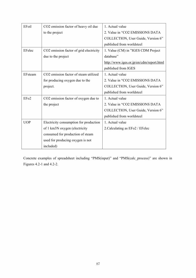
87
EFoil CO2 emission factor of heavy oil due
to the project
1. Actual value
2. Value in “CO2 EMISSIONS DATA
COLLECTION, User Guide, Version 6”
published from worldsteel
EFelec CO2 emission factor of grid electricity
due to the project
1. Value (CM) in ”IGES CDM Project
database”
http://www.iges.or.jp/en/cdm/report.html
published from IGES
EFsteam CO2 emission factor of steam utilized
for producing oxygen due to the
project.
1. Actual value
2. Value in “CO2 EMISSIONS DATA
COLLECTION, User Guide, Version 6”
published from worldsteel
EFo2 CO2 emission factor of oxygen due to
the project
1. Actual value
2. Value in “CO2 EMISSIONS DATA
COLLECTION, User Guide, Version 6”
published from worldsteel
UOP Electricity consumption for production
of 1 km3N oxygen (electricity
consumed for production of steam
used for producing oxygen is not
included)
1. Actual value
2.Calculating as EFo2 / EFelec
Concrete examples of spreadsheet including “PMS(input)” and “PMS(calc_process)” are shown in
Figures 4.2-1 and 4.2-2.

88
Figure 4.2-1 An example of JCM spreadsheet “PMS(input)”
Table 1: Parameters to be monitored ex post(a) (b) (c) (d) (e) (f) (g) (h) (i) (j)
Monitoringpoint No.
Parameters Description of dataEstimated
ValuesUnits
Monitoringoption
Source ofdata
Measurement methods andprocedures
Monitoring frequencyOther
comments
1 WPcoal,yProject consumption of coal in coalgasification furnace(CGF) for ladlepreheating furnace(LPF)
1,020 drt t-coal/y CMonitoreddata
- Measuring the weight of the chargedcoal- Integration of the weights
at every charge to LPF
2 QPng,yProject consumption of natural gasfor LPF
0 km3N-ng/y CMonitoreddata
- Measuring the integrating natural gasflowmeter equipped to LPF
at the start and the end ofthe period
3 QPoil,yProject consumption of heavy oil forLPF
0 m3-oil/y CMonitoreddata
- Measuring the integrating oil flowmeterequipped to LPF
at the start and the end ofthe period
4-1 EPcgf,yProject consumption of elecricity forCGF
200 MWh/y CMonitoreddata
- Measuring the Watt-hour meterequipped to CGF
at every charge to CGF
4-2 EPld,yProject consumption of elecricity forLPF
400 MWh/y CMonitoreddata
- Measuring the Watt-hour meterequipped to LPF
at every charge to LPF
5 QOld,yProject consumption of oxygenproduced in oxygen productionplant(OPP) for LPF
300 km3N-o2/y CMonitoreddata
- Measuring the integrating O2flowmeter equipped to LPF
at the start and the end ofthe period
5 QOp,ld,yProject consumption of purchaseoxygen for LPF
0 km3N-o2/y CMonitoreddata
- Measuring the integrating O2flowmeter equipped to LPF
at the start and the end ofthe period
6 QOother,yProject consumption of oxygenproduced in OPP for other plantexcept for LPF
10,212 km3N-o2/y CMonitoreddata
- Measuring the integrating O2flowmeter equipped to the other plantexcept for LPF
at the start and the end ofthe period
7 EPo2 plant,yProject consumption of elecricity forOPP
2,064 MWh/y CMonitoreddata
- Measuring the Watt-hour meterequipped to OPP
at every charge to OPP
8 WSyProject consumption of steam forOPP
1,314 t-steam/y CMonitoreddata
- Measuring the integrating steamflowmeter equipped to OPP
at the start and the end ofthe period
9 TPtap,yProject average tappingtemperature of molten steel in EAF
1,600 deg C. CMonitoreddata
- Measuring molten steel tempareture inEAF before tapping from EAF
at every charge from EAF
10 WPbillet,y Project production of billet 220,000 t-billet/y CMonitoreddata
- Counting the number of the producedbillets divided into each billet size.- Having data of the weight per a billetof each billet size by direct mesuaring orby calculating using billet size anddencity.- Calculating "Pbillet,ref" from thenumber of the produced billets and theweight per a billet of each billet size
at the start and the end ofthe period
Table 2: Project-specific parameters to be fixed ex ante(a) (c) (d)
ParametersEstimated
ValuesUnits
EFcoal 3.257 t-CO2/dry t-coal
EFelec CO2 emission factor of grid electricity 0.564 t-CO2/MWh
EFo2 CO2 emission factor of oxygen 0.355 t-CO2/km3N-o2
EFng CO2 emission factor of natural gas 2.014 t-CO2/km3N
EFoil CO2 emission factor of heavy oil 2.907 t-CO2/m3
EFsteam CO2 emission factor of steam 0.195 t-CO2/t-steam
WRbillet 250,000 t-billet
WRcoal 1,700 dry t-coal
QRng 0 km3N-ng
QRoil 0 m3-oil
ERcgf 200 MWh
ERld 400 MWh
ERld 400 MWh
TRtap,y 1,600 deg C.
Table3: Ex-ante estimation of CO2 emission reductions
Unitst-CO2/y
[Monitoring option]Option AOption BOption C
Reference elecricity consumed at LPFMonitored data,- Measuring the Watt-hour meter equipped to LPF
Reference average tapping temperature of moltensteel in EAF
Monitored data,- Measuring molten steel tempareture in EAF before tapping
The data is sourced from "CO2 EMISSIONS DATA COLLECTION,User Guide, Version 6"(worldsteel) unless instructed by the JointCommittee.
Monitored data,- Measuring the integrating natural gas flowmeter equipped to LPFMonitored data,- Measuring the integrating heavy oil flowmeter equipped to LPF
Reference production of billet
Monitored data.- Counting the number of the produced billets divided into eachbillet size.- Having data of the weight per a billet of each billet size by directmesuaring or by calculating using billet size and dencity.- Calculating "Pbillet,ref" from the number of the produced billetsand the weight per a billet of each billet size
Reference consumption of elecricity for LPFMonitored data,- Measuring the Watt-hour meter equipped to LPF
Reference consumption of coal for CGF
Reference consumption of elecricity for CGF
Reference consumption of natural gas for LPF
Based on the amount of transaction which is measured directly using measuring equipments (Data used: commercial evidence such as invoices)Based on the actual measurement using measuring equipments (Data used: measured values)
Based on public data which is measured by entities other than the project participants (Data used: publicly recognized data such as statistical data and specifications)
CO2 emission factor of coalThe data is sourced from "CO2 EMISSIONS DATA COLLECTION,User Guide, Version 6"(worldsteel) unless instructed by the JointCommittee.
Monitored data,- Measuring the weight of the charged coal
CO2 emission reductions
Monitored data,- Measuring the Watt-hour meter equipped to CGF
1,502
Reference consumption of heavy oil for LPF
(b)
Description of data
(e)
Source of data
(f)
Other comments
The combined margin(CM) emission factor in Viet Nam from"IGES CDM project database"(http://www.iges.or.jp/en/cdm/report.html)The data is sourced from "CO2 EMISSIONS DATA COLLECTION,User Guide, Version 6"(worldsteel) unless instructed by the JointCommittee.The data is sourced from "CO2 EMISSIONS DATA COLLECTION,User Guide, Version 6"(worldsteel) unless instructed by the JointCommittee.The data is sourced from "CO2 EMISSIONS DATA COLLECTION,User Guide, Version 6"(worldsteel) unless instructed by the JointCommittee.

89
Figure 4.2-2 An example of JCM spreadsheet “PMS(calc_process)”
1. Calculations for emission reductions Fuel type Value Units Parameter
Emission reductions during the period of year y 1,502 t-CO2/y ERy
2. Selected default values, etc.
CO2 emission factor of coal ----- 3.257 t-CO2/dry t-coal EFcoal
CO2 emission factor of electricity ----- 0.564 t-CO2/MWh EFelec
CO2 emission factor of oxygen ----- 0.355 t-CO2/km3N-o2 EFo2
CO2 emission factor of natural gas ----- 2.014 t-CO2/km3N EFng
CO2 emission factor of heavy oil ----- 2.907 t-CO2/m3 EFoil
CO2 emission factor of steam ----- 0.195 t-CO2/t-steam EFsteamElectricity equivalent value of oxygen ----- 0.629 MWh/km3N-o2 UOP
3. Calculations for reference emissions
Reference emissions during the period of year y 5,170 t-CO2/y REy
CO2 emissions by reheating ladle fossil fuel 5,537 t-CO2 REcoal
CO2 emissions from coal 5,537 t-CO2 REcoal
CO2 emissions from natural gas 0.0 t-CO2 REng
CO2 emissions from heavy oil 0.0 t-CO2 REoil
CO2 emissions by electricity consumption electricity 338 t-CO2 REelec
4. Calculations of the project emissions
Project emissions during the period of year y 3,668 t-CO2/y PEy
CO2 emissions by reheating ladle fossil fuel 3,322 t-CO2/y PEcoal
CO2 emissions from coal 3,322 t-CO2/y PEcoal
CO2 emissions from natural gas 0 t-CO2/y PEng
CO2 emissions from heavy oil 0 t-CO2/y PEoil
CO2 emissions by electricity consumption electricity 338 t-CO2/y PEelec
59 MWh/y EPld o2,y
CO2 emissions by steam consumption steam 7 t-CO2/y PEsteam
38 t-steam/y WPsteam.ySteam consumption for production ofoxygen used at ladle preheating
Electricity consumption for oxygen used atladle preheating

90
4.3 JOINT CREDITING MECHANISM METHODOLOGY OF “INTRODUCTION OF
REGENERATIVE BURNER TO THE REHEATING FURNACE FOR SEMI-PROCESSED
STEEL”
The old burners, which are attached to the reheating furnace are replaced to the regenerative burners
in the process of producing steel bars by rolling the heated billets. The burner combustion exhaust gas
is discharged to the outside of the system at high temperatures until introduction of the project.
However, after introduction of the project, heat loss to the outside of the system is significantly
reduced. Therefore, the consumption of fossil fuel for the burners and relating CO2 emission are
reduced.
JCM Proposed Methodology Form
Cover sheet of the Proposed Methodology Form
Form for submitting the proposed methodology
Host Country Socialist Republic of Vietnam
Name of the methodology proponents
submitting this form
JFE Steel
JFE Techno-Research
Sectoral scope(s) to which the Proposed
Methodology applies
4. Manufacturing industries
Title of the proposed methodology, and
version number
Introduction of Regenerative Burner to the
Reheating furnace for Semi-processed Steel
Version number: 1.0
List of documents to be attached to this form
(please check):
The attached draft JCM-PDD:
Additional information
Date of completion
History of the proposed methodology
Version Date Contents revised
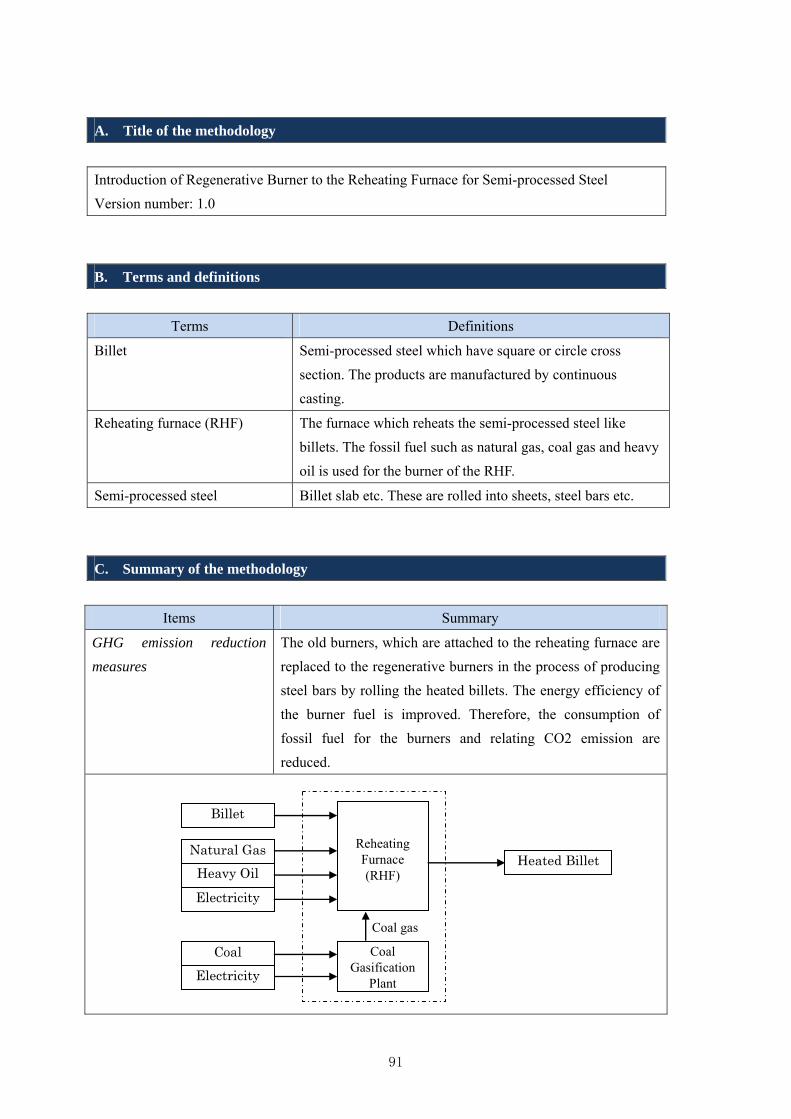
91
A. Title of the methodology
Introduction of Regenerative Burner to the Reheating Furnace for Semi-processed Steel
Version number: 1.0
B. Terms and definitions
Terms Definitions
Billet Semi-processed steel which have square or circle cross
section. The products are manufactured by continuous
casting.
Reheating furnace (RHF) The furnace which reheats the semi-processed steel like
billets. The fossil fuel such as natural gas, coal gas and heavy
oil is used for the burner of the RHF.
Semi-processed steel Billet slab etc. These are rolled into sheets, steel bars etc.
C. Summary of the methodology
Items Summary
GHG emission reduction
measures
The old burners, which are attached to the reheating furnace are
replaced to the regenerative burners in the process of producing
steel bars by rolling the heated billets. The energy efficiency of
the burner fuel is improved. Therefore, the consumption of
fossil fuel for the burners and relating CO2 emission are
reduced.
Billet
Electricity
Coal
Natural Gas
Heavy Oil
Reheating Furnace(RHF)
Heated Billet
Coal Gasification
PlantElectricity
Coal gas

92
Calculation of reference
emissions
The reference data measurement period should be provided
before the project. The reference emissions are calculated from
the quantities of electricity, fossil fuel etc. at the RHF or at the
coal gasification plant during the reference period and their CO2
emission factors.
Calculation of project
emissions
The project emissions are calculated from electricity, fossil fuel
etc. at the RHF, coal gasification plant and CO2 emission
factors during the project period.
Monitoring parameters 1) Supply of billets
2) Consumption of natural gas at the RHF
3) Consumption of heavy oil at the RHF
4) Consumption of electricity at the RHF
5) Consumption of coal at the coal gasification plant
6) Consumption of electricity at the coal gasification plant
D. Eligibility criteria
This methodology is applicable to projects that satisfy all of the following criteria.
Criterion 1 The project of reducing consumption of fossil fuel by improving the energy
efficiency at RHF for billet.
Criterion 2 The burners of the RHF are not regenerative type before the project.
Criterion 3 The burners of introducing to the RHF are regenerative type.
Criterion 4 The burner fuel is natural gas, heavy oil, or coal gas.
E. Emission Sources and GHG types
Reference emissions
Emission sources GHG types
Natural gas, which is consumed at the RHF CO2
Heavy oil, which is consumed at the RHF CO2
Electricity, which is consumed at the RHF CO2
Coal, which is consumed at the coal gasification plant CO2
Electricity, which is consumed at the coal gasification plant CO2
Project emissions
Emission sources GHG types
Natural gas, which is consumed at the RHF CO2

93
Heavy oil, which is consumed at the RHF CO2
Electricity, which is consumed at the RHF CO2
Coal, which is consumed at the coal gasification plant CO2
Electricity, which is consumed at the coal gasification plant CO2
F. Establishment and calculation of reference emissions
F.1. Establishment of reference emissions
The reference data measurement period should be provided before the project. The
consumption of electricity and fossil fuels (coal, natural gas, heavy oil) at the RHF and the coal
gasification plant, also the supply of billets to the RHF are measured. The CO2 emission factors
are of the project period. The yearly supply of billets to the RHF during the project is used
when the reference values are converted to the yearly amounts.
F.2. Calculation of reference emissions
REy = (REng + REoil + REelec + REcoal + REelec2 )/WRSbillet ×WPSbillet,y
Where,
REy : Reference emissions in year y [t-CO2/y]
REng : CO2 emission from natural gas, which is consumed at the RHF during the
reference period [t-CO2]
REoil : CO2 emission from heavy oil, which is consumed at the RHF during the
reference period [t-CO2]
REelec : CO2 emission from electricity, which is consumed at the RHF during the
reference period [t-CO2]
REcoal : CO2 emission from coal, which is consumed at the coal gasification plant
during the reference period [t-CO2]
REelec2 : CO2 emission from electricity, which is consumed at the coal gasification plant
during the reference period [t-CO2]
WRSbillet : Supply of billets to the RHF during the reference period [t-billet]
WRSbillet,y : Yearly supply of billets to the RHF during the project [t-billet/y]
REng = QRng × EFng
Where,
QRng : Consumption of natural gas at the RHF during the reference period [km3N]

94
EFng : CO2 emission factor for the natural gas [t-CO2/km3N]
REoil = QRoil × EFoil
Where,
QRoil : Consumption of heavy oil at the RHF during the reference period [m3]
EFoil : CO2 emission factor for the heavy oil [t-CO2/ m3]
REelec = ERrhf × EFelec
Where,
ERrhf : Consumption of electricity at the RHF during the reference period [MWh]
EFelec : CO2 emission factor for the Viet Nam grid system [t-CO2/MWh]
REcoal = WRc × EFcoal
Where,
WRc : Consumption of coal at the coal gasification plant during the reference period
[t]
EFcoal : CO2 emission factor for the coal[tCO2/t]
REelec2 = ERcgp × EFelec
Where,
ERcgp : Consumption of electricity at the coal gasification plant during the reference
period [MWh]
EFelec : CO2 emission factor for the Viet Nam grid system [t-CO2/MWh]
G. Calculation of project emissions
PEy = (PEng + PEoil + PEelec + PEcoal + PEelec2)
Where,
PEy : Project emissions in year y [t-CO2/y]
PEng : CO2 emission from natural gas, which is consumed at the RHF during the
project [t-CO2/ y]
PEoil : CO2 emission from heavy oil, which is consumed at the RHF during the
project [t-CO2/ y]
PEelec : CO2 emission from electricity, which is consumed at the RHF during the
project [t-CO2/ y]
PEcoal : CO2 emission from coal, which is consumed at the coal gasification plant

95
during the project [t-CO2/ y]
PEelec2 : CO2 emission from electricity, which is consumed at the coal gasification plant
during the project [t-CO2/ y]
PEng = QPng, y × EFng
Where,
QPng, y : Consumption of natural gas at the RHF during the project [km3N/ y]
EFng : CO2 emission factor for the natural gas [t-CO2/km3N]
PEoil = QPoil, y × EFoil
Where,
QPoil, y : Consumption of heavy oil at the RHF during the project [m3/ y]
EFoil : CO2 emission factor for the heavy oil [t-CO2/ m3]
PEelec = EPrhf, y × EFelec
Where,
EPrhf, y : Consumption of electricity at the RHF during the project [MWh/ y]
EFelec : CO2 emission factor for the Viet Nam grid system [t-CO2/MWh]
PEcoal = WPcoal, y × EFcoal
Where,
WPcoal, y : Consumption of Coal at the coal gasification plant during the project [t/ y]
EFcoal : CO2 emission factor for the coal [t-CO2/t]
PEelec2 = EPcgf, y × EFelec
Where,
EPcgf, y :Consumption of electricity at the coal gasification plant during the project
[MWh/ y]
EFelec : CO2 emission factor for the Viet Nam grid system [t-CO2/MWh]
H. Calculation of emissions reductions
Emission reductions are calculated as the difference between the reference emissions and
project emissions, as follows.

96
DPRy = REy - PEy
Where,
DPRy :GHG emission reductions in year [t-CO2/y]
I. Data and parameters fixed ex ante
The source of each data and parameter fixed ex ante is listed as below.
Parameter Description of data Source
EFng CO2 emission factor for the
natural gas
1) The data is calculated from the carbon content of
the natural gas, which is measured by chemical
analysis.
2) The data is sourced from "CO2 EMISSIONS
DATA COLLECTION, User Guide, Version 6"
(worldsteel).
(unless instructed by the Joint Committee)
EFoil CO2 emission factor for the
heavy oil
1) The data is calculated from the carbon content of
the heavy oil, which is measured by chemical
analysis.
2) The data is sourced from "CO2 EMISSIONS
DATA COLLECTION, User Guide, Version 6"
(worldsteel).
(unless instructed by the Joint Committee)
EFelec CO2 emission factor for the
Viet Nam grid system
The combined margin(CM) emission factor in Viet
Nam from "IGES CDM project data base"
(http://www.iges.or.jp/en/cdm/report.html)
EFcoal CO2 emission factor for the
coal
1) The data is calculated from the carbon content of
the coal, which is measured by chemical analysis.
2) The data is sourced from "CO2 EMISSIONS
DATA COLLECTION, User Guide, Version 6"
(worldsteel). The factor of steam coal is the first
choice in the 2nd case.
(unless instructed by the Joint Committee)
As an example, JCM Methodology Spreadsheets (Input sheet, Calculation process sheet) are shown in
Figure 4.3-1 and Figure 4.3-2.

97
Figure 4.3-1 Input sheet
JCM_VN_F_PMS_ver01.0
Joint Crediting Mechanism Proposed Methodology Spreadsheet Form (input sheet) [Attachment to Proposed Methodology Form]
Table 1: Parameters to be monitored ex post(a) (b) (c) (d) (e) (f) (g) (h) (i) (j)
Monitoringpoint No.
Parameters Description of dataEstimated
ValuesUnits
Monitoringoption
Source of data Measurement methods and proceduresMonitoringfrequency
Othercomments
(1) WPSbillet, y Supply of billets to the RHFper a year ex post
250,000 t-billet/ y C Monitored data
- Counting the number of the supplied billets divided intoeach billet size.- Having data of the weight per a billet of each billet sizeby direct mesuaring or by calculating using billet size anddencity.- Calculating "Sbillet, y" from the number of the suppliedbillets and the weight per a billet of each billet size
once at theend of theyearlymonitoring
(2) QPng, y Consumption of natural gasat the RHF
0 km3N/ y C Monitored data- Measuring the integrating flowmeter equipped to theRHF
at the startand the endof the period
(3) QPoil, y Consumption of heavy oil atthe RHF
2,250 m3/ y C Monitored data- Reading the delivery amount of the oil described in theinvoice
at everydelivery
(4) EPrhf, y Consumption of electricity atthe RHF
2,500 MWh/ y C Monitored data - Measuring the Watt-hour meter equipped to the RHFat the startand the endof the period
(5) WPcoal, y Consumption of coal at thecoal gasification plant
0 t/ y C Monitored data- Reading the delivery amount of the coal described in theinvoice
at everydelivery
(6) EPcgf, y Consumption of electricity atthe coal gasification plant
0 MWh/ y C Monitored data- Measuring the Watt-hour meter equipped to the coalgasification plant
at the startand the endof the period
Table 2: Project-specific parameters to be fixed ex ante(a) (c) (d)
ParametersEstimated
ValuesUnits
EFng 2.014 t-CO2/km3N
EFoil 2.907 t-CO2/m3
EFelec 0.564 t-CO2/MWh
EFcoal 2.461 t-CO2/t
WRSbillet 50,000 t-billet
QRng 0 km3N
QRoil 500 m3
ERrhf 500 MWh
WRc 0 t
ERcgf 0 MWh
Table3: Ex-ante estimation of CO2 emission reductionsUnits
tCO2/y
[Monitoring option]Option AOption BOption C
(f)
Other comments
(e)
Source of data
1) The data is calculated from the carbon content of the natural gas, which is measuredby chemical analysis.2) The data is sourced from "CO2 EMISSIONS DATA COLLECTION, User Guide,Version 6"(worldsteel).(unless instructed by the Joint Committee)
Based on the actual measurement using measuring equipments (Data used: measured values)
(b)
Description of data
CO2 emission reductions
726
CO2 emission factor for the natural gas
Based on public data which is measured by entities other than the project participants (Data used: publicly recognized data such as statistical data and specifications)
CO2 emission factor for the coal
1) The data is calculated from the carbon content of the steam coal, which is measuredby chemical analysis.2) The data is sourced from "CO2 EMISSIONS DATA COLLECTION, User Guide,Version 6"(worldsteel). The factor of steam coal is the first choice in the 2nd case.(unless instructed by the Joint Committee)
Consumption of heavy oil at the RHF duringthe reference period
Based on the amount of transaction which is measured directly using measuring equipments (Data used: commercial evidence such as invoices)
CO2 emission factor for the heavy oil
1) The data is calculated from the carbon content of the heavy oil, which is measured bychemical analysis.2) The data is sourced from "CO2 EMISSIONS DATA COLLECTION, User Guide,Version 6"(worldsteel).(unless instructed by the Joint Committee)
CO2 emission factor for the Viet Nam gridsystem
The combined margin(CM) emission factor in Viet Nam from "IGES CDM project database"(http://www.iges.or.jp/en/cdm/report.html)
Consumption of natural gas at the RHFduring the reference period
Monitored data.- Measuring the integrating flowmeter equipped to the RHF
Monitored data.- Reading the delivery amount of the oil described in the invoice
Consumption of electricity at the RHF duringthe reference period
Monitored data.- Measuring the Watt-hour meter equipped to the RHF
Supply of billets to the RHF during thereference period
Monitored data.- Counting the number of the supplied billets divided into each billet size.- Having data of the weight per a billet of each billet size by direct mesuaring or bycalculating using billet size and dencity.- Calculating "Sbillet, ref" from the number of the supplied billets and the weight per abillet of each billet size
Consumption of coal at the coal gasificationplant during the reference period
Monitored data.- Reading the delivery amount of the coal described in the invoice
Consumption of electricity at the coalgasification plant during the reference period
Monitored data.- Measuring the Watt-hour meter equipped to the coal gasification plant

98
Figure 4.3-2 Calculation process sheet
JCM_VN_F_PMS_ver01.0
1. Calculations for emission reductions Fuel type Value Units Parameter
Emission reductions during the period of year y 727 tCO2/y DPRy
2. Selected default values, etc.
CO2 emission factor for the natural gas ----- 2.014 t-CO2/km3N EFng
CO2 emission factor for the heavy oil ----- 2.907 t-CO2/m3 EFoil
CO2 emission factor for the Viet Nam grid system ----- 0.564 t-CO2/MWh EFelec
CO2 emission factor for the coal ----- 2.461 t-CO2/t EFcoal
3. Calculations for reference emissions
Reference emissions during the period of year y 8,678 tCO2/y REy
Supply of billets to the RHF during the reference period ----- 50,000 t-billet WRSbillet
Consumption of natural gas at the RHF during the reference peri Fossil Fuel 0 km3N QRng
Consumption of heavy oil at the RHF during the reference period Fossil Fuel 500 m3 QRoil
Consumption of electricity at the RHF during the reference perio Electricity 500 MWh ERrhf
Consumption of coal at the coal gasification plant during the refe Fossil Fuel 0 t WRc
Consumption of electricity at the coal gasification plant during th Electricity 0 MWh ERcgf
4. Calculations of the project emissions
Project emissions during the period of year y 7,951 tCO2/y PEy
Supply of billets to the RHF per a year ex post ----- 250,000 t-billet/ y WPSbillet, y
Consumption of natural gas at the RHF Fossil Fuel 0 km3N/ y QPng, y
Consumption of heavy oil at the RHF Fossil Fuel 2,250 m3/ y QPoil, y
Consumption of electricity at the RHF Electricity 2,500 MWh/ y EPrhf, y
Consumption of coal at the coal gasification plant Fossil Fuel 0 t/ y WPcoal, y
Consumption of electricity at the coal gasification plant Electricity 0 MWh/ y EPcgf, y
Joint Crediting Mechanism Proposed Methodology Spreadsheet Form (Calculation Process Sheet)
[Attachment to Proposed Methodology Form]
99
5. REPORTING OF ENERGY SAVING TECHNOLOGIES TO
VIETNAM
Seminar in Hanoi was held in January 2015, in order to widely dissement JCM scheme and to report
the study results of this project, to government officials related to JCM and concerned personnel in
steel industry in Vietnam.
At the same time, during 1st or 2nd visit to Vietnam, we visited government departments related to
JCM and explained JCM scheme and activities of this project
This chapter shows the meeting with government departments, and Seminar in Hanoi.
5.1 PRIOR EXPLANATION TO THE GOVERNMENT OFFICIALS
During 1st or 2nd visit to Vietnam, JFE group visited government officials related to JCM, and
explained JCM scheme and activities of this project. The followings show the departments which JFE
group visited, and attendance at the meeting
(1) MOIT(Ministry Of Industry and Trade)General Directorate of Energy
Date: Sep. 15th ,2014
Attendance:
Mr. Pham Thanh Tung: Director of International Cooperation Department
Mr. Nguyen Van Long: Deputy Director General Science Technology and Energy Efficiency
Department
Visitors:Sogo:JFE Steel Corporation, Sawa, Shimizu: JFE Techno-Research Corporation
(2) MOIT Heavy Industry Department
Date: Sep. 16th ,2014
Attendance:
Mr. Bui Quang Chuyen: Deputy Director General of Heavy Industry Department
Mr. Tran Van Long: Official of Heavy Industry Department
Visitors:Sogo:JFE Steel Corporation, Sawa, Shimizu: JFE Techno-Research Corporation
(3) MOIT Department of Science and Technology
Date: Sep. 16th ,2014
Attendance:
Mr. Le Viet Cuong:
Mr. Pham Truong Son: (Official)
Mr. Do Xuan Dong: (Official)
Visitors:Sogo:JFE Steel Corporation, Sawa, Shimizu: JFE Techno-Research Corporation
(4) MONRE (Ministry Of Natural Resources & Environment) International Cooperation
Department
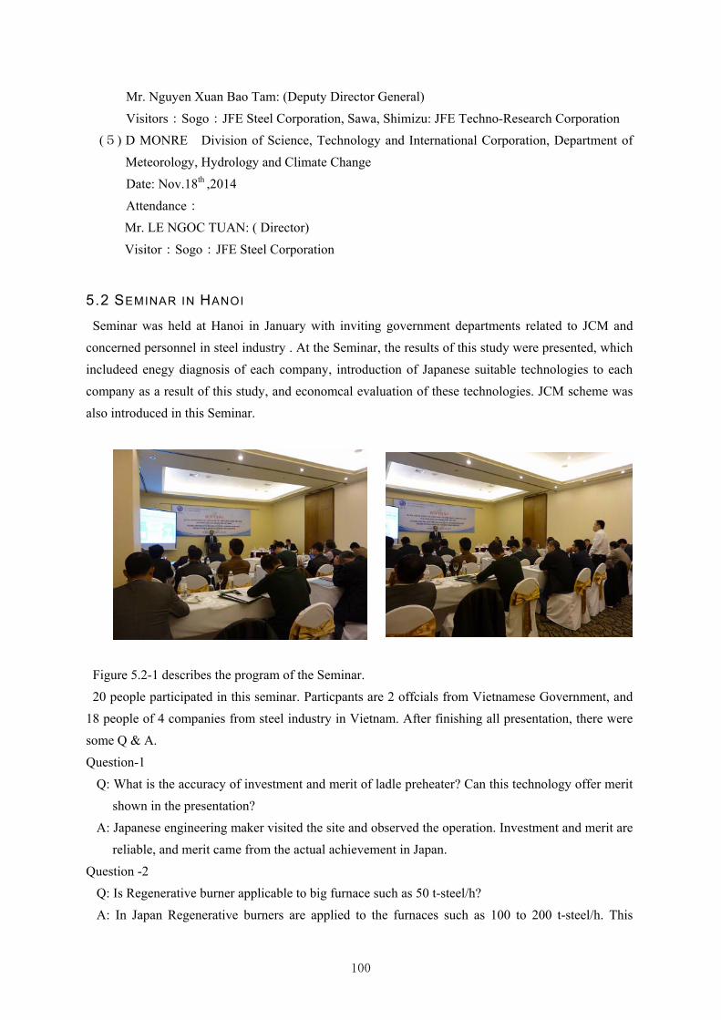
100
Mr. Nguyen Xuan Bao Tam: (Deputy Director General)
Visitors:Sogo:JFE Steel Corporation, Sawa, Shimizu: JFE Techno-Research Corporation
(5) D MONRE Division of Science, Technology and International Corporation, Department of
Meteorology, Hydrology and Climate Change
Date: Nov.18th ,2014
Attendance:
Mr. LE NGOC TUAN: ( Director)
Visitor:Sogo:JFE Steel Corporation
5.2 SEMINAR IN HANOI
Seminar was held at Hanoi in January with inviting government departments related to JCM and
concerned personnel in steel industry . At the Seminar, the results of this study were presented, which
includeed enegy diagnosis of each company, introduction of Japanese suitable technologies to each
company as a result of this study, and economcal evaluation of these technologies. JCM scheme was
also introduced in this Seminar.
Figure 5.2-1 describes the program of the Seminar.
20 people participated in this seminar. Particpants are 2 offcials from Vietnamese Government, and
18 people of 4 companies from steel industry in Vietnam. After finishing all presentation, there were
some Q & A.
Question-1
Q: What is the accuracy of investment and merit of ladle preheater? Can this technology offer merit
shown in the presentation?
A: Japanese engineering maker visited the site and observed the operation. Investment and merit are
reliable, and merit came from the actual achievement in Japan.
Question -2
Q: Is Regenerative burner applicable to big furnace such as 50 t-steel/h?
A: In Japan Regenerative burners are applied to the furnaces such as 100 to 200 t-steel/h. This

101
technology is suitable to big furnaces.
Question -3
Q: There is an explanation about slag door and door burner. In this meaning what is the suitable
operation of EAF?
A: Furnace pressure ±0 is ideal operation which aims at no air infiltration and no energy loss toward
outside of the furnace. Slag door helps this operation, and door burner gives more efficient
operation.
Question -4
Q: How much is proper hot metal ratio to EAF? Are there any operations using hot metal in Japan?
A: Proper hot metal ratio depends on the cost of iron sources, so it differs from site to site. And
operation using hot metal is very rare in Japan.
There are all technical questions. After finishing the Seminar, there were still some more technical
questions.

102
Figure 5.2-1 AGENDA for Seminar
“Future JCM project applying effective Japanese excellent energy
saving technologies to Vietnam Steel Industry”
20 JANUARY 2015
NIKKO HOTEL, HANOI
Agenda
9:00 – 9:10 Introduction Kazumasa Sogo
(JFE Steel Corporation)
9:10 – 9:40 “Technologies Cutomized list”
The introduction of the Customized List
to Iron and Steel Industry in Vietnam
Masuto SHIMIZU
(JFE Techno-Research Corporation)
Reporting the results of energy daiagnosis in Iron and Steel Industry in Vietnam
9:40 – 10:20 “Summary of Result Activity of
A-Company in 2014”
Yoshitaka Sawa
(JFE Techno-Research Corporation)
Coffee Break
10:35– 11:15 “Summary of Result Activity of
B-Company in 2014”
Masuto SHIMIZU
(JFE Techno-Research Corporation)
JCM (The Joint Crediting Mechanism)
11:15 – 11:45 “JCM Scheme”
The introduction of JCM and JCM
Pocedure
Kazumasa Sogo
(JFE Steel Corporation)
11:45 – 12:00 Discussion

103
6. ECONOMICAL ANALYSIS FOR COMMERCIALIZATION
Production capacity in the Vietnam steel industry is a mixture of facilities in operation for a long
time and newer ones introduced in line with the market opening since 2000. We confirmed through
the study that there is still a room for introduction of Japan’s newest technology because it is not fully
applied to even newer facilities yet.
The spread of the newest technology depends largely on its profitability and, as described in the
sub-sections “economic evaluation”, it may be hardly accomplished without any financial assistance
such as a subsidy at this point. However, we expect that the profitability will be improved as energy
price increases in the future.
Here, we analyzed the economic effectiveness due to the spread of the technology in consideration
of the future increase in energy price.
As described in Chapter 2, it is expected that energy price will increase in Vietnam in the future.
Here, we estimate the profitability on the assumption that electricity price rises by 30% and fuel price
15% in 2020. Furthermore, for a sensitivity analysis, we also estimate another case where electricity
price rises by 50% and fuel price 25%. The results are shown in Figure 6.1-1, 6.1-2 and 6.1-3. The
calculations are performed by assuming that investment amounts are same and without considering
any subsidies. The current economic evaluations as mentioned above are represented in the upper
rows of each of the figures.
Figure 6.1-1 Economical Evaluation of each technology in A-Company
Electrical Arc Furnace Reheating Furnace
Technology
Direct Suction
Dust Collector
and Installment
of Oxy-fuel
burner system
Electrode
Regulation and
Automation
Control for EAF
Optimization
Regenerative
burner :
Replacement of
all burners
Regenerative
burner :
Replacement of
partial burners
Present condition
Pay Back years 8.1 2.7 8.7 6.1
IRR (%) 4.6 35.5 2.8 10.8
In the case that Electric power price +30%, and fuel price +15%
Pay Back years 6.0 2.0 7.4 5.1
IRR (%) 12.2 48.5 6.3 14.8
In the case that Electric power price +50%, and fuel price +25%
Pay Back years 5.0 1.7 6.7 4.6
IRR (%) 16.9 56.8 8.4 17.2

104
Figure 6.1-2 Economical Evaluation of each technology to EAF in B-Company
Electrical Arc Furnace
Technology
Installment of
Oxy-fuel
burner
system
with oil as a
fuel
Installment of
Oxy-fuel burner
system
with coal as a
fuel
Electrode
Regulation and
Automation
Control for EAF
Optimization
Electrode
Regulation and
Automation
Control for EAF
Optimization
with hardware
Present condition
Pay Back years No return 9.6 7.2 27.6
IRR (%) - 0.8 7.4 ▲ 17.3
In the case that Electric power price +30%, and fuel price +15%
Pay Back years No return 7.1 5.3 18.6
IRR (%) - 8.0 15.5 ▲ 11.3
In the case that Electric power price +50%, and fuel price +25%
Pay Back years No return 6.0 4.4 15.3
IRR (%) - 12.3 20.4 ▲ 8.0
Figure 6.1-3 Economical Evaluation of heating technologies in B-Company
Heating Technology
Technology
Ladle Preheater
with oxygen/fuel
burner
Regenerative burner :
Replacement of all
burners
Regenerative burner :
Replacement of partial
burners
Present condition
Pay Back (years) 3.0 20.2 13.2
IRR (%) 33.3 Δ12.0 Δ5.0
In the case that Electric power price +30%, and fuel price +15%
Pay Back years 2.6 16.6 11.1
IRR (%) 38.4 ▲ 8.9 ▲ 1.9
In the case that Electric power price +50%, and fuel price +25%
Pay Back years 2.4 14.8 10.0
IRR (%) 41.7 ▲ 7.1 0.0
Because the loan period is generally about six years in Vietnam and the valid payout period is aimed
at not more than six years, the evaluations for each technology are given as follows.
For EAF technology, we evaluate that it is difficult to apply the technologies using auxiliary fuel
with burners newly installed (e.g. Direct Suction Dust Collector and Installment of Oxy-fuel burner

105
system to A-Company; Installment of Oxy-fuel burner system with oil as a fuel or Installment of
Oxy-fuel burner system with coal as a fuel to B-Company) from the view point of profitability.
There remains the possibility of applying them only if electricity price rise greatly exceeds fuel price
rise, nevertheless we can not expect this at present.
The profitability of the electrode control technology (e.g. Electrode Regulation and Automation
Control for EAF Optimization to both A-Company and B-Company) will be more improved as
electricity price rises because the technology contributes only to reducing power consumption. As
mentioned above, however, there remains some possibility that we can not achieve our purpose. We
should study more in case that the hardware needs revamping simultaneously.
The utilization of the oxygen/fuel burner for preheating ladles (e.g. Ladle Preheater to B-Company)
is sufficiently profitable technology. This is, as mentioned above, successfully applicable at the
moment when a steelworks holds its in-house oxygen plant.
The applicability of regenerative burners to RHFs (e.g. Regenerative burner to both A-Company
and B-Company) depends much on fuel price, and it will be difficult to replace all the existent
burners even if electricity price is raised by 50% and fuel price 25%. If partial replacement of burners
is applied to a RHF with oil or natural gas used, it will become profitable when fuel price rises in the
future. However, if coal is used as a fuel at RHF as in B-Company, partial replacement will be
less profitable because the price of coal is lower than that of oil or natural gas. Therefore it is less
possible in such a case to adopt the technology in terms of energy saving. There will be a chance of
the installation when a new furnace is set up or an existent one is revamped for reinforcement.
According to these points of view and the results of sensitivity analysis, we forecast the reduction of
CO2 emissions in the future by using the predicted values.
The Vietnamese government has set numerical targets for steel and iron production as of 2025 as
follows.12
・ Expand the total steel production to 38 – 39 million tons,
・ Expand the pig iron production to 20 million tons by 2025.
The Vietnam’s demand for steel is expected to grow in future as the economy is likely developing
and construction of blast furnaces is currently progressing. Based on the numerical targets above, we
assumed that EAF will produce 18.5 million tons per year of crude steel and reheat furnaces will treat
38.5 million tons of semi-finished steel in Vietnam as of 2025. We assume each of the adoption rates
for the technologies as follows.
・ Oxy-fuel burner system for EAF: this technology will be unlikely spread widely because its
profitability is based on the premise of the price difference between electricity and fuel, while
12 Feasibility Study project for the BOCM (FY2012) “Study for applying effective Japanese excellent
energy saving and CO2 Reduction technologies to newly planned Integrated Steel Works in Viet Nam (Policy
proposal and project development Study)” ReportMarch,15th,2013 JFE Steel Corporation JFE
Techno-Research Corporation

106
energy prices are expected to rise in future. Moreover, this does not necessarily reduce CO2
emissions. Therefore we exclude this from the applicable technologies.
・ Electrode Control Technology for EAF: this technology is expected to spread in accordance
with development in the operational skills, while there are still old-fashioned facilities in
Vietnam and the operational skills are immature yet. Moreover, this will improve the
profitability as electricity price rises. Therefore, this is expected to spread in future and we
assume that its adoption rate will be about 50% as of 2025.
・ Oxygen/fuel Burner for Ladle Preheating: this technology is most probable to spread at present,
and we need to make the technology more known to the steelmakers. As described above, the
profitability changes depending on whether a steelwork holds its in-house oxygen plant. We
expect that many steelworks will hold their own oxygen plants in future because it is
economically advantageous for them to do so. Therefore, we assume that 50% of all the
steelworks will hold their in-house oxygen plants and that 50% of them (i.e. 25% of all the
steelworks) will adopt this technology as of 2025. Furthermore, we have the utilization of
regenerative burner for ladle preheating as an applicable technology for a steelworks without its
in-house oxygen plant, and we can also expect the combined spread of these technologies.
・ Regenerative Burner Technology for RHF: this technology is still insufficient in its profitability
when it is applied by revamping the existent facility, even if fuel price rises. Higher rise in fuel
price could give profitability to partial application of this technology, nevertheless full
application would be difficult in such a case. However, we are expecting that there will be new
installment, improvement and reinforcement of steel facilities by 2025, and the application of
regenerative burner can have sufficient profitability at this timing. Therefore, we assume that the
adoption rate will be 50%.
Based on the premises and the assumptions described above, the reduction of CO2 emissions as of
2025 is summarized in Fig. 6.1-4.
Figure 6.1-4 Forecast of dissemination of technologies and CO2 reduction rate at 2025
Technology
Electrode Regulation
and Automation Control
for EAF Optimization
Ladle Preheater
with oxygen/fuel
burner
Reheating Furnace
Regenerative burner
Disementation
Ratio in Vietnam
(mil t-steel/y)
18.5 mil t-steel/y
x 50%
=9.25
18.5 mil t-steel/y
x 50% x 50%
=4.63
38.5 mil t-steel/y
x 50%
=19.25
CO2 Reduction
ratio
(kg-CO2/t-steel)
5.64
(10kwh/ t-steel)
4.9
*1)
10.5
*2)
CO2 Reduction
(t-CO2/y) 52,170 22,600 202,120

107
*1) Adopt half of the value of B-Company with replacement of all burners (the value is approximately
double in case of use of coal gasification gas)
*2) Adopt the value of A-Company (he value is approximately double in case of use of coal
gasification gas)
As explained above, we can expect much reduction of CO2 emissions by introducing these
technologies from now on.

108
7. SUMMERY
Energy saving technologies study about contrastive 2 companies was executed this fiscal year. One
has a long history of steel making, and another started its operation after 2000. Although they are
contrastive, the followings are recognized
1. Steel making technologies of both companies are still immature,.
2. There is much room to introduce new technologies. At the same time, it is hard to find the base
and capability which brings up technical knowledge and skills.
3. There are still not many concerns about Japanese technologies, and in many places, technologies
from China have been adopted because of economical priority.
At the same time, from this study, there are few chances for Japanese technoloties to be introduced
to Vietnam steel Indsustry from the economical point of view, because Japanese technologies costs
pretty high and the energy costs in Vietnam are low. These situations lead to the followings
propossals.
7.1 POLICY RECCOMENDATION ON JCM IN VIETNAM
At present in Vietnam steel industry, recognition of Japanese technologies is low, and almost no
concern about JCM. Considering these situation, the following measures are effective for
implementation of Japanese technologies.
1.To bring up recognition of Japanese technologies
Even the technologies which are very popular and concerned in Japan have little recognition. Only
the explanation of Japanese technologies cannot lead to the businesses even though the technologies
are superior and excellent. This is partly because Japanese technologies costs relatively high, and at
the same time, the technologies in steel industry in Vietnam are not enough matured.
In this situation,
① To provide effective and feasible technologies through the observation and study of the
targeted companies.
② To evaluate and estimate the actual effect of new technologies with using actual data
③ To be understood the effectiveness of technologies through these evaluation
④ To make an opportunity to come in contact with the Japanese superior technology. Visit to
Japan by key technology officer is one choice.
Technologies’ proposals including site survey will be required to promote introduction of Japanese
technologies and at the same time the explanation together with recommendation of operation
improvement may show superiority of Japanese technologies.
2.To embody the Japanese technologies in Vietnam with using JCM
Economical performance is one of the big factors to hamper the introduction of Japanese
technologies. There are some cases that same kinds of technologies are imported other than Japan.

109
However, Japanese technologies are better than those from other countries, and it can offer higher
effect. It is very important to break economical barrier for Japanese technologies, and effective use of
JCM scheme can support to show superiority. Track record of Japanese technologies is important,
and application of feasible technologies should be taken first priority even though it has small
investment and small effect.
In the future, energy prices in Vietnam are expected to increase, and for that moment, Japan must
prepare for such situation.
3.Future Development of Understanding and practical use of JCM
It is not exaggeration that steel industry in Vietnam has no information about JCM. At the same
time, some government officials have opinions that it is hard to understand JCM because Ministry of
Economy Trade, and Industry and Ministry of the Environment have different JCM scheme.
Therefore more simple explanation is desirable.
Another big issue in the steel industry in Vietnam is that enough data collection systems are not
established. This leads to the concern whether appropriate MRV system is plausible or not, in order
to promote JCM. System of Management cycle, that is cycle of Plan-Do-Check-Action, is not
popular in Vietnam, and Introduction of Management cycle is also recommended to promote JCM.
4.Barriers to promote Energy Saving Action
Some barriers to introduce energy saving action rise from study and discussion with 2 companies,
from meeting with government officials, and from the situation mentioned above. Based on these
understandings, barriers are wrapped up in the following table.
It is a pleasure to consider these barriers at intergovernmental meeting on JCM consultation.
Items Barrier Synopsis
Budget,
Human resource ● Lack of budget, Lack of Engineering ability
Inside the
company Lack of information
and knowledge
● Lack of knowledge for Energy Saving Technology
● Lack of examination and management capacity of introducing
technologies because in Vietnam EPC (Engineering,
Procurement and Construction) is generally all executed by
foreign engineering makers
● Lack of data, data reduction, and examination. Lack of system
for accepting the introduction of new technologies
Domestic
situation
Uncertainty of the
steel demand
● Uncertainty of the steel demand in the future because of
domestic declining demand and pressure of imported steel from
abroad (at the same time expectation of demand growth in the
future )

110
Lack of information
● Insufficient System sharing technical information between steel
companies which is popular in Japan.
● Insufficient information about EPC which is all ordered to
foreign companies because of lack of ability of the domestic
facilities maker and construction supplier
Competition
environment among
companies
● The competition about quality and the energy saving (energy
intensity) is not common
High interest rate ● A high interest rate on the occasion of financing under the
influence of inflation
Common
items in
rising
nations
High facility cost
● many equipments from overseas from the performance and
quality point of view, because of insufficient ability of the
domestic facilities maker
● Higher estimate for the equipment because of a currency risk
and the credit risk of the individual company
Handling of JCM
● Even some government-affiliated cannot understand JCM
because of different support scheme in Ministry of Economy,
Trade and Industry, and Ministry of the Environment
Energy saving policy
● Not much aid package to the energy saving, and insufficient
understanding for the need of energy saving target and the
regulation
● Little policy about the spread of so-called management cycle
such as Plan-Do-Check-Action
Government
Uncertainty of energy
prices
● Hard environment of enhancing energy saving because of low
energy price (The present price of power is kept in a low level
not directly to reflect its cost)
● These lead to a high business-related energy consumption and
low energy saving investment
7.2 SUMMERY, SUGGESTION AND PROPOSAL FOR THE ACTIVITY FOR NEXT
FISCAL YEAR
This study indicates much room to introduce Japanese superior technologies to steel industry in
Vietnam. However, environment does not reach to the stage to introduce Japanese technologies from
the economical point of view. In this situation, JCM scheme may support to make some technologies
economical and feasible. Whether these technologies are applied or not, highly depends on the
judgment of targeted company.
On the other hand, in the case that the projects are accepted by these companies, they require more
precise study like check of data and its reliability, estimation of volume of site work, check of data

111
about MRV.
Inexpensive equipment, uptake of various merits etc must be studied in order to improve
economical situation.
At the same time, management cycle, that is Plan-Do-Check-Action, must be radicated for
achieving the embodiment of technologies.
During this study, we were able to visit 2 steel companies and many government officials to study
energy saving technologies. We would like to express our sincere greatness for those who welcomed
us during this study for their great help and kindness at the end.

112
ANNEX1 COMMENTARY ON TECHNOLOGIES POSITIVE LIST
Hot Conveyor Transport of Hot DRI/HBI to EAF Hot Conveyor Transport of Hot DRI/HBI to EAF Figure Annex1-1 No.1: Hot DRI/HBI Charging to the EAF
(From SOACT)
Figure Annex1-2 No.2: Scrap Preheating (ex. Ecological and Economical Arc Furnace)
(From http:/www.steelplantech.co.jp)

113
Figure Annex1-3 No.4: Aluminum Alloy Conductor Arm for Supporting Electrode
(From NIKKO Industry CO.,LTD)
<DC furnace>Graphite hearth
electrode
Hearth Electrode
Electric room
DC reactor(DCL)
trans
VCBThyristor
Transformerstation
High-frequencyfilter
<DC furnace>Graphite hearth
electrode
Hearth Electrode
Electric room
DC reactor(DCL)
trans
VCBThyristor
Transformerstation
High-frequencyfilter
Figure Annex1-4 No.5: DC Electro Arc Furnace
(From NEDO Handbook)

114
Figure Annex1-5 No.6: Oxy-fuel Burners/Lancing (or Super Sonic Burner )
(From NIKKO Industry CO.,LTD)
HeatExchanger
Cooling waterCirculation
pump Boiling feedWater pump
Deaerator
Condensatepomp
From applicationsystemWHRB steam drum
Accumulator
To applicationsystem
Steam drum
Super heater
BoilerCirculation
pump
Make-upwater
HeatExchanger
Cooling waterCirculation
pump Boiling feedWater pump
Deaerator
Condensatepomp
From applicationsystemWHRB steam drum
Accumulator
To applicationsystem
Steam drum
Super heater
BoilerCirculation
pump
Make-upwater
Figure Annex1-6 No.8: Waste Heat Recovery from EAF
(From JASE-World)

115
Horizontal Type Vertical Type
Waste gas 170deg.CWaste gas
COG920 Mcal/h
Air 20deg.C
1000deg.C
Waste gas 4-way selector Valve
Heat Storage material(ceramic honeycomb)
Air
1000deg.CCOG
600 Mcal/h
Regenerative burnerConventional burnerFig Non heat recovery type burner ladle
Drying deviceRegenerative burner-type ladle
Drying device
from brochure of Chugai Ro
Making it possible to preheat a number of ladles in a single installation.Furthermore, the high-temperature heating of the ladles is possible with the ladles attached closely together. The preheating of a number of ladles in a single installation is enabled by sliding movement. Furthermore, opening and closing movement back and forth enables the high temperature heating of the ladles with lids attached closely together.
Figure Annex1-7 No.9.1: Regenerative Burner Total System for Ladle Preheating
(From NEDO Handbook、Photo. from CHUGAI RO CO.,LTD)
Figure Annex1-8 No.9.2: Oxygen Burner Total System for Ladle Preheating
(From CHUGAI RO CO.,LTD)

116
EAF Process Optimization by Off-gas Analysis
Power Input Control
・Off Gas Analysis
・Temp, O2, CO, CO2, H2, N2 H2O
Carbon & Oxygen Injection
Natural Gas & Lime Injection
EAF Process Optimization by Off-gas Analysis
Power Input Control
・Off Gas Analysis
・Temp, O2, CO, CO2, H2, N2 H2O
Carbon & Oxygen Injection
Natural Gas & Lime Injection
Figure Annex1-9 No.11.2: Control and Automation for EAF Optimization
(From SOACT)
EAF
Voltage inverter
Control Panel
Scrap data presetting
Automatic Scrap Meltdown Timing Judgment System by Acoustic Spectrum Analysis for AC EAF
Meltdown signal
Data collection
Current transformer
Signals from EAF
Touch panel
Sound signal
Current
Microphone
EAF
Voltage inverter
Control Panel
Scrap data presetting
Automatic Scrap Meltdown Timing Judgment System by Acoustic Spectrum Analysis for AC EAF
Meltdown signal
Data collection
Current transformer
Signals from EAF
Touch panel
Sound signal
Current
Microphone
Figure Annex1-10 No.11.3: Control and Automation for EAF Optimization
(From Home page of DAIDO STEEL)
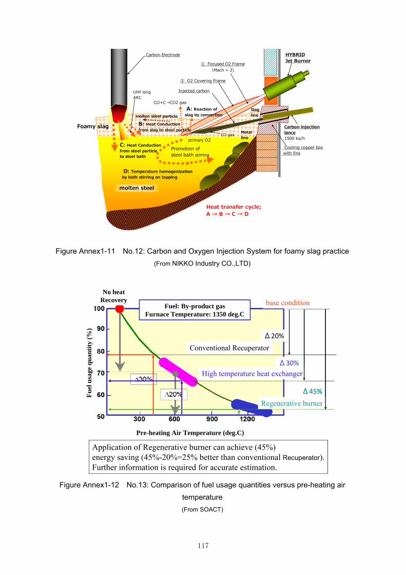
117
molten steel
② O2 Covering Frame
① Focused O2 Frame (Mach = 2)
Carbon Electrode HYBRIDJet Burner
Carbon injectionlance1500 kg/h
Cooling copper box with fins
D: Temperature homogenizationby bath stirring on tapping
UHP longARC
Promotion ofsteel bath stirring
C: Heat Conductionfrom steel particleto steel bath
Slagline
Metalline
Injected carbon
CO+C→CO2 gas
CO gas
B: Heat Conductionfrom slag to steel particle
molten steel particle
primary O2
A: Reaction of slag by convection
Foamy slag
Heat transfer cycle;A → B → C → D
Figure Annex1-11 No.12: Carbon and Oxygen Injection System for foamy slag practice
(From NIKKO Industry CO.,LTD)
base condition
High temperature heat exchanger
Regenerative burner
Δ30%
Δ45%
Application of Regenerative burner can achieve (45%) energy saving (45%-20%=25% better than conventional Recuperator).Further information is required for accurate estimation.
Fuel: By-product gasFurnace Temperature: 1350 deg.C
No heat Recovery
Pre-heating Air Temperature (deg.C)
Fu
el u
sage
qua
nti
ty (
%)
Δ20%
Conventional Recuperator
Figure Annex1-12 No.13: Comparison of fuel usage quantities versus pre-heating air
temperature
(From SOACT)

118
Preheating temperature >1000℃ by Regenerative Burner Total System
FuelFuel
Burner ABurner B
CeramicRegenerator B Ceramic
Regenerator A
Exhaust gas 200 deg.C Switch valve
Air
Regenerative burners, using temperature resistant ceramic heat media, can recover approximately 85% of waste heat from high temperature exhaust gas from reheating furnaces or ladle preheating by directly introducing high temperature exhaust gas into heat media and alternate switching between heat storage and preheating of combustion air. This high performance burner technology achieves superior fuel gas saving and compact reheating furnace equipment. It is desirable to install this system when new furnace is introduced, because the cost will be saved compared to modification of furnaces.
Figure Annex1-13 No.13.1: Combustion Air Preheating for reheating furnace
(From SOACT)
En
ergy
con
serv
atio
n r
atio
(%
)
Reheating Furnace(continuous)Reheating Furnace(batch)LadleHeat treatment furnace(continuous)Heat treatment furnace(batch)Gas treatment furnaceMelting furnace
Treatment Temperature (deg.C)
Actual results shows approximately 30% reduction of fuelIn case of Reheating furnace, the average is 10-20% reduction compared to the furnace with conventional Recuperator.(These results are mainly from Japanese industries, and the energy saving effectFor Reheating furnace depends on the range of revamping)
In case of ReheatingFurnace
10 -20% Reduction
Field test project167 furnaces
Figure Annex1-14 No.13.1: Actual Results of application of Regenerative burner
(From SOACT)
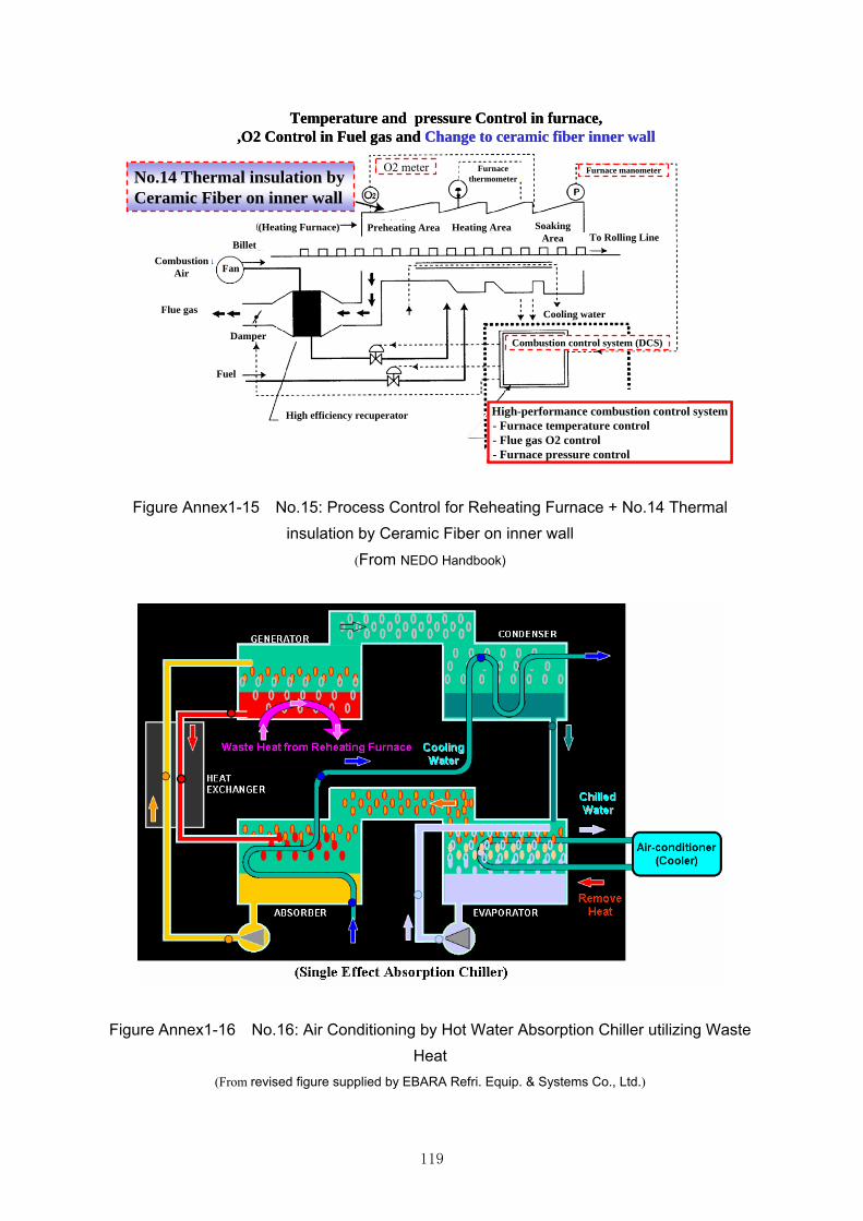
119
Temperature and pressure Control in furnace, ,O2 Control in Fuel gas and Change to ceramic fiber inner wall
O2 meter Furnace manometer
(Heating Furnace) Preheating Area Heating Area SoakingArea To Rolling Line
Billet
CombustionAir Fan
Flue gas
Damper
Cooling water
High efficiency recuperator
Combustion control system (DCS)
Fuel
FurnacethermometerNo.14 Thermal insulation by
Ceramic Fiber on inner wall
High-performance combustion control system- Furnace temperature control- Flue gas O2 control- Furnace pressure control
Figure Annex1-15 No.15: Process Control for Reheating Furnace + No.14 Thermal
insulation by Ceramic Fiber on inner wall
(From NEDO Handbook)
Figure Annex1-16 No.16: Air Conditioning by Hot Water Absorption Chiller utilizing Waste
Heat
(From revised figure supplied by EBARA Refri. Equip. & Systems Co., Ltd.)
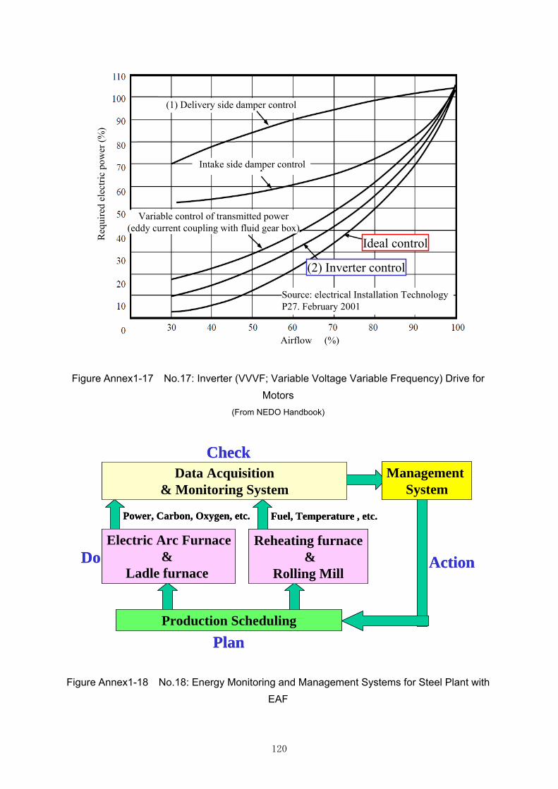
120
(1) Delivery side damper control
Intake side damper control
Ideal control
(2) Inverter control
Variable control of transmitted power(eddy current coupling with fluid gear box)
Source: electrical Installation TechnologyP27. February 2001
Airflow (%)
Req
uire
d el
ectr
ic p
ower
(%
)
(1) Delivery side damper control
Intake side damper control
Ideal control
(2) Inverter control
Variable control of transmitted power(eddy current coupling with fluid gear box)
Source: electrical Installation TechnologyP27. February 2001
Airflow (%)
Req
uire
d el
ectr
ic p
ower
(%
)
Figure Annex1-17 No.17: Inverter (VVVF; Variable Voltage Variable Frequency) Drive for
Motors
(From NEDO Handbook)
Data Acquisition & Monitoring System
Management System
Electric Arc Furnace&
Ladle furnace
Reheating furnace&
Rolling Mill
Production Scheduling
Power, Carbon, Oxygen, etc. Fuel, Temperature , etc.
Do
Check
Action
Plan
Data Acquisition & Monitoring System
Management System
Electric Arc Furnace&
Ladle furnace
Reheating furnace&
Rolling Mill
Production Scheduling
Power, Carbon, Oxygen, etc. Fuel, Temperature , etc.
Do
Check
Action
Plan
Figure Annex1-18 No.18: Energy Monitoring and Management Systems for Steel Plant with
EAF