module 15 - bryant electric marriott... · module 15 mechanical, plumbing & electrical december...
TRANSCRIPT

Module
15Mechanical, Plumbing &
Electrical
December 2007
Revised: July 2010
CFRST LEED Volume Program
This Module includes Marriott’s CFRST LEED® Volume Program (LVP) requirements based on the U.S. Green Building Council (USGBC) LEED® for New Construction Version 2.2 rating system. Only participants in the CFRST LVP Program are able to use LEED Version 2.2. The text in “green” with green background and with the “Marriott Spirit to Preserve” logo, applies only to the CFRST LVP Program Version 2.2 requirements.
Revised July 2010
Contents15.1 GeneralRequirementsforMEPSystems 1
15.2 Mechanical&HVACSystems 2
15.3 PlumbingSystems 15
15.4 ElectricalSystems 23
15-M1 EnvironmentalRequirements-Table 13-14
15-P2 Plumbing/UtilityRequirements-Table 22
15-E1 High-RiseEmergencyElectricalSystems-Table 30
15-E2 EmergencyElectricalSystems-Diagram 31
15-E3 LightingCriteria-Table 34-36
Figures
Module Organization• This Module is a part of an integrated series of 16 Modules.• Coordination with information from other Modules is required.• The reference symbol <XX> is used to indicate a Module reference that includes related information.
Marriott Con�dential & Proprietary InformationThe contents of the Design Standards are confidential and proprietary to Marriott International, Inc. and may not be reproduced, disclosed, distributed or used without the express permission of an authorized representative of Marriott.
Copyright, Marriott International, Inc., unpublished material. All rights reserved.
Revised:July2010This Module supersedes all previous versions.
Includes the Courtyard LEED® Volume Program (LVP).
Courtyard by Marriott
December 2007
15-Mechanical,Plumbing&Electrical
15–B Design Standards © Marriott International, Inc.

Revised July 2010
15.1 General Requirements for MEP Systems
A. Overview: Information contained in this Module is intended to set minimum Mechanical (HVAC), Electrical and Plumbing (MEP) system requirements and does not provide complete project design solutions.
B. References: The “design guideline drawings”, Interior Design / Décor package, Project Manual Master (PMM - specifications) and Design Standards model a typical Courtyard program. For “custom” and non-typical projects, see Module <GR> - General Requirements, “Establishing Hotel Design Criteria“ for integrating the Market Analysis, project Facilities Program, Prototype documents and Design Standards.Custom and non-prototype projects include “high-rise” buildings as defined in Module <14> and effect the design and construction of MEP systems. Prior to beginning the design process, contact Marriott A&C Engineering for these project types, applications, expanded design criteria and project specific requirements.1. Codes and Standards: Comply with the more stringent
of governing laws, applicable governing codes and regulations and these Design Standards.
2. Requirements in these Standards will be installed by the mechanical (HVAC), plumbing or electrical contractors and must be included in the respective design documents with references to other documents as required.
3. Building Height: Buildings greater than six stories or 75 ft. high and higher are classified as “high-rise” and require different engineering criteria such as smoke evacuation, stair pressurization, fire sprinkler system, etc.; consult with Marriott A&C Engineering.
4. Fire Protection / Life Safety: See Module <14>; on applicable MEP engineering drawings, show required fire and life safety systems.
5. LEED® Volume Program (LVP):a. ASHRAE 55-2004 - Thermal Environmental
Conditions for Human Occupancyb. ASHRAE 62.1-2004 - Ventilation for Acceptable
Indoor Air Qualityc. ASHRAE 90.1-2004 - Energy Standard for
Buildingsd. New Buildings Institute - Advanced Buildings-
“Core Performance Guide” www.newbuildings.orge. LEED-NC Version 2.2 - U.S. Green Building
Council; www.usgbc.org
Mechanical,Plumbing&Electrical-15
December 2007
Courtyard by Marriott
15–1Design Standards © Marriott International, Inc.
Revised July 2010
LEED EAc1 - Optimize Energy Performance: Comply with Option 3 - Advanced Buildings “Core Performance Guide” for design requirements and prescriptive compliance.
C. Dimensions, Sizes and Measurements: In this Standard, conversions from English to metric (SI) units are approximate. Verify, coordinate and confirm product and material dimensions for required design applications.
D. Equipment Selection: Select and provide equipment, components and specified materials rated for applicable service, environ-ment, temperatures and pressures.1. Equipment designed for interior use may not be installed
outside.2. Design and construct outside equipment for project
specific conditions complete with factory applied corrosion resistant coatings.
15.2 Mechanical & HVAC Systems
A. General Requirements: Comply with the above “General Requirements for MEP Systems” in this Module.
B. Codes and Standards:1. FM Global: Fired pressure vessels and their safety trains
(controls that include combustion safeguards, safety shut-off valves, over temperature protection and pressure relief valves) are required to be FM Global approved.
2. Building Pressures: Design building systems to maintain positive pressure, maintain environmental requirements (temperature and humidity) and ensure guest comfort. Provide outside air intake quantities to exceed building exhaust quantities by 10% minimum on a floor-by-floor basis. Provide complete airflow matrix showing supply, return, exhaust, and outside air quantities on each HVAC plan.
C. Building Cooling / Heating Load Calculations:1. Reference: Latest edition of ASHRAE Handbook of
Fundamentals or equivalent governing design standard.2. Method: Utilize the Cooling Load Temperature
Difference (CLTD) as defined in ASHRAE.3. Guestrooms / Guest Units: Load calculations are not
required for guestrooms. See sizing criteria in this module.4. Environmental Requirements: Design and select
equipment to maintain indoor space temperature and humidity conditions when using ventilation requirements for occupants and internal heat gain in compliance with Figure 15-M1 “Environmental Requirements - Table” in this Module.
Courtyard by Marriott
December 2007
15-Mechanical,Plumbing&Electrical
15–2 Design Standards © Marriott International, Inc.

Revised July 2010
5. Outdoor Design Conditions: Utilize the ASHRAE 1% annual cooling dry bulb and mean coincident wet bulb (columns 9c and 9d) and the 99.6% heating dry-bulb temperature.
6. “Core Performance Guide” - Mechanical System Design: Comply with Section 1.4 for design requirements.
D. HVAC (Heating, Ventilation & Air Conditioning) Systems:1. General Design Parameters:
a. Design a cost effective, quiet and energy efficient HVAC system. Design system to be as automatic as practical, and allow for easy maintenance by local service personnel.
b. Location of supply, return and exhaust grilles in pub-lic spaces is included in the Design Guideline draw-ings (Reflected Ceiling Plans).
2. Noise Criteria: Design systems and select mechanical equipment to minimize the transmission of sound and vibration. Select equipment, air distribution systems, and air devices not to exceed NC 35 in Guestrooms and Public Areas and NC 40 in Back-of-House Spaces.
3. Stairwells: Provide heating in stairwells to maintain minimum 50° F (10° C).
4. Entry Vestibules: In cold climates, provide supplemental heat to maintain minimum 50˚ F (10˚ C).
5. Indoor Pool Space: Comply with ASHRAE Applications Handbook 2007, Chapter 4 section on natatoriums.
6. LEED EAp3 - Fundamental Refrigerant Management: CFC based refrigerants not permitted.
7. “Core Performance Guide”: Comply with Section 2.10 - Dedicated Mechanical Systems requirements
E. Indoor Air Quality (IAQ): High IAQ is a critical component of guest comfort and must be achieved through the proper design of the building air systems.1. Standard References: Provide air quality, including filtering
and humidity control, in compliance with ASHRAE Standard 62.1–2004, Ventilation for Acceptable Indoor Air Quality and ASHRAE Standard 55-2004 Thermal Environmental Conditions for Human Occupancy. Maintain humidity levels and outside air quantities in compliance with Figure 15-M1: Environmental Requirements - Table in this Module.
2. Carbon Monoxide Sensors: Provide to control parking structure ventilation systems.
3. LEED® EQc7.1 - Thermal Comfort Design: Comply with ASHRAE Standard 55-2004.
4. ASHRAE Standard 62.1-2004: Comply with Sections 4 through 7 - Ventilation for Acceptable Indoor Air Quality for minimum requirements.
Mechanical,Plumbing&Electrical-15
December 2007
Courtyard by Marriott
15–3Design Standards © Marriott International, Inc.
Revised July 2010
5. “Core Performance Guide” - IAQ Performance: Comply with Section 2.3 for minimum IAQ requirements.
Credit EQc3.2 - Building Flushout: The Marriott LVP program does not include this credit.
F. Energy Efficiency: At a minimum, design the HVAC system in compliance with ASHRAE Standard 90.1-2004 Energy Efficiency in Buildings.
“Core Performance Guide” - Mechanical Equipment Efficiency: Comply with Section 2.9 for efficiency requirements.
G. Air Handling Systems Design Considerations: Provide HVAC systems for habitable public and back-of-house spaces.1. For air handling units (AHU’s) with >50% outside air
quantity use the ASHRAE 0.4% annual evaporation wet bulb and mean coincident dry bulb temperature (column 10a and 10b). Select AHU’s with <50% outside air quantities using the ASHRAE 1% annual cooling dry bulb mean coincident wet bulb (columns 9C and 9d).
2. Air Handling Unit (AHU) Locations: For ease of access and maintenance locate AHU’s inside the building in dedicated mechanical rooms.
3. Outside Air Intakes: Locate in fully secured areas and if possible 9’-0” minimum above grade.
4. Mechanical Rooms are not used as a return air plenum. Hard duct outside air and return air to AHU’s.
5. Locate outside air intakes as high above grade as possible preferably in a secure location.
6. Contactors: Provide totally silent type (solid-state or mercury) contactors for air handling units, PTAC units, fans and electric heaters in or adjacent to public spaces and guestrooms.
7. Exhaust Systems: Provide for pool equipment rooms, parking structures, toilet rooms, vending areas, electric rooms, laundries and any other areas producing odors, fumes or excessive heat.
8. Ventilation: Provide mechanical ventilation to non-conditioned spaces to maintain a minimum winter temperature of 50° F (10° C) and maximum summer temperature of 90° F (32°C).
9. Fans: Centrifugal type, except parking structure fans, which may be propeller type.
10. Air Handling Systems: Design in compliance with ASHRAE Standard 62.1-2004, Ventilation Rate Procedure in Section 6.2 for Ventilation of Acceptable Indoor Air Quality.
Courtyard by Marriott
December 2007
15-Mechanical,Plumbing&Electrical
15–4 Design Standards © Marriott International, Inc.

Revised July 2010
11. Economizers: Provide economizers to comply with ASHRAE Standard 90.1-2004 and operate in compliance with the “Core Performance Guide” Section 2.13 - Fundamental Economizer Performance.
H. Public & Back-of-House AHU’s1. AHU Type: See Table 15-M1; provide direct expansion
(DX) split system horizontal type draw-thru low-pressure constant volume units with supply fan, DX cooling coil, electric heating coil, combination filter / mixing boxes with exterior, low velocity filters.a. Cleanable interior with closed cell insulation and
positive drain type stainless steel drain pan.b. Utilize freeze stats to protect coils from freezing
by shutting down fans.2. Design Supply Rate: Minimum of six air changes per
hour.3. Thermostats: In public spaces, place in areas not
accessible to guests and allow for the selection of temperatures between 68o to 78o F (20o to 26o C).
Credit EQc6.2 - Controllability of Systems - Thermal Comfort: Provide a separate thermostat in each occupied space.
4. Zones: See the Design Guideline Drawing, “Systems Criteria Plan - HVAC” for the mechanical system zones.
5. “Core Performance Guide” - Mechanical Equipment: Comply with Section 2.9 - Table 2.9.1 for efficiency requirements.
6. “Core Performance Guide” - Demand Control Ventilation: Comply with Section 2.11.a. Install CO2 sensors in breathing zone of each
occupied public and back of house spaces at 36 to 60 inches above finish floor.
b. Satisfies partial compliance of LEED EQc1 - Outdoor Air Delivery Monitoring.
7. “Core Performance Guide” - Fundamental Economizer: Comply with performance requirements of Section 2.13.
I. Guestrooms (Guest Units) & Suites:1. Prototypical Properties: For low-rise, prototypical
hotel applications, provide packaged terminal air conditioning (PTAC) units with electric heat.a. Do not specify PTAC units that feature cooling
capacities in excess of the values listed below, as oversized units do not allow for the appropriate humidity control within guestrooms.
Mechanical,Plumbing&Electrical-15
December 2007
Courtyard by Marriott
15–5Design Standards © Marriott International, Inc.
Revised July 2010
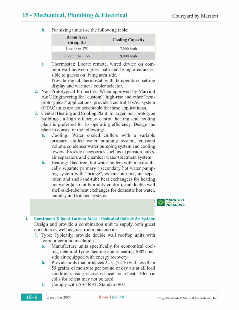
b. For sizing units use the following table:RoomArea(insq.ft.) CoolingCapacity
Less than 375 7,000 btuh
Greater than 375 9,000 btuh
c. Thermostat: Locate remote, wired device on com-mon wall between guest bath and living area acces-sible to guests on living area side.
Provide digital thermostat with temperature setting display and warmer / cooler selector.
2. Non-Prototypical Properties: When approved by Marriott A&C Engineering for “custom”, high-rise and other “non-prototypical” applications, provide a central HVAC system (PTAC units are not acceptable for these applications).
3. Central Heating and Cooling Plant: In larger, non-prototype buildings, a high efficiency central heating and cooling plant is preferred for its operating efficiency. Design the plant to consist of the following:a. Cooling: Water cooled chillers with a variable
primary chilled water pumping system, constant volume condenser water pumping system and cooling towers. Provide accessories such as expansion tanks, air separators and chemical water treatment system.
b. Heating: Gas fired, hot water boilers with a hydrauli-cally separate primary / secondary hot water pump-ing system with “bridge”, expansion tank, air sepa-rator, and shell-and-tube heat exchangers for heating hot water (also for humidity control), and double wall shell-and-tube heat exchanges for domestic hot water, laundry and kitchen systems.
4. “Core Performance Guide” - Mechanical Equipment: Comply with Section 2.9 - Table 2.9.3 for efficiency requirements.
J. Guestrooms & Guest Corridor Areas - Dedicated Outside Air System: Design and provide a combination unit to supply both guest corridors as well as guestroom makeup air.1. Type: Typically, provide double wall rooftop units with
foam or ceramic insulation.a. Manufacture units specifically for economical cool-
ing, dehumidifying, heating and reheating 100% out-side air equipped with energy recovery.
b. Provide units that produces 22ºC (72ºF) with less than 59 grains of moisture per pound of dry air at all load conditions using recovered heat for reheat. Electric coils for reheat may not be used.
c. Comply with ASHRAE Standard 90.1.
Courtyard by Marriott
December 2007
15-Mechanical,Plumbing&Electrical
15–6 Design Standards © Marriott International, Inc.

Revised July 2010
2. Guestrooms: Provide vertical risers in the shaft from a horizontal roof or attic mounted distribution system that supplies air quantity equal to 5 cfm/person + 0.06 cfm/sf.a. Hard duct makeup to a sidewall supply register.b. Coordinate register locations with Interior Design.
3. Corridors: Provide 2 air changes per hour minimum, supplied from vertical guestroom risers to ceiling mounted registers. Do not provide ceiling supported fan coil units.
4. Smoke Exhaust Mode: During this mode, makeup air system and toilet exhaust system operate as normal. See smoke exhaust system requirements for guest corridors in this Module.
5. “Core Performance Guide” - Mechanical Equipment: Comply with Section 2.9 - Table 2.9.1 for efficiency requirements.
6. Credit EQc1 - Outdoor Air Delivery Monitoring: Provide current sensors to monitor fan status as the means to measure minimum ventilation requirements for 100% outdoor air systems. A visual or audible alarm will generate when the fan status varies by more than 10% from the set point.
K. Exhaust Systems:1. Guest Bathroom Exhaust: Provide 50 cfm,
incremental ceiling mounted exhaust fan in each guest bathroom, less than 1.0 sone sound rating, tied to the light switch and either ducted to the exterior individually or subducted into vertical sheetmetal risers with roof mounted goosenecks with bird screen.
Exhaust: Duct exhaust air to associated dedicated outside air system for energy recovery.
2. Additional Exhaust Requirements: Provide the following:a. 1 cfm / sf exhaust in guest laundry, electric
rooms, linen rooms, pool storage, vending areas and service elevator lobby or vestibule. Include air transfer from corridor.
b. 2 cfm / sf exhaust in public restrooms.c. Locate exhaust outlets no closer than 20 ft. away
from outside air intakes and operable windows.d. Where fireplaces are included, duct to roof and
locate outlets 50 ft. minimum from outside air intakes or operable windows.
Mechanical,Plumbing&Electrical-15
December 2007
Courtyard by Marriott
15–7Design Standards © Marriott International, Inc.
Revised July 2010
L. Ductwork:1. Type: Low and medium velocity galvanized sheet
metal constructed in compliance with SMACNA Standards or non-metallic duct systems approved by Marriott A&C Engineering.a. Seal supply and return ductwork joints and seams
with hard-cast. For exterior roof mounted duct-work provide with 1 inch (25 mm) minimum rigid phenolic insulation and UV resistant aluminum jacket with waterproof seams.
b. Runouts to diffusers may be medium pressure rated, externally insulated, spiral wound, flexible duct with a maximum length of 8 ft. (2.4 m).
2. Size ductwork for maximum velocity as follows:a. 2,000 fpm: Main supply ducts. b. 1,500 fpm: Branch ducts and return / exhaust
systems.c. 800 fpm: Ducts serving room terminal air
devices.d. Duct Friction Loss: Not to exceed 0.10 inch w.c.
per 100 ft. of duct.3. Turning Vanes: Provide turning vanes in rectangular
elbows greater than 45 degrees.4. Miscellaneous Ductwork: Fabricate indoor pool and
pool chlorine storage room ductwork from stainless steel with welded, watertight connections.
5. Duct Insulation: Acoustic lining may be used but must have an impervious face located in the air stream and must be thoroughly sealed including joints prior to joining ducts.
6. Fire Dampers: Provide where required, to meet necessary fire ratings of structural, wall and ceiling systems.
7. Balancing Devices:a. Balancing Dampers: Provide balancing damp-
ers in all supply and exhaust risers, and at all registers / diffusers.
b. Splitter Dampers: Avoid use of multiple splitter dampers in individual duct systems.
8. Air Devices: Diffusers, registers, and grilles used in guestrooms and other public areas must be factory primed for custom finish painting by others. Coordinate with Interior Design and painting specification.
9. Flues: Provide factory fabricated, stainless steel flue for gas fired boilers and fireplaces (if provided) vented to building exterior.
Courtyard by Marriott
December 2007
15-Mechanical,Plumbing&Electrical
15–8 Design Standards © Marriott International, Inc.

Revised July 2010
M. Smoke Exhaust System:1. Design Considerations: This system is intended to control
migration of smoke into means of egress (exit passageways) and to maintain acceptable conditions for occupants in protected areas by exhausting smoke from the smoke zone only.a. Consult Module <14> and Marriott A&C Engineering
for application criteria. Provide a complete engi-neered smoke exhaust system in high-rise buildings with minimum 8 air changes per hour.
b. Design system to exhaust smoke from lobby, atriums, restaurant / dining areas, meeting rooms greater than 35 m² (350 sq. ft.), exercise rooms, kitchens and guest corridors.
c. At back of house areas (BOH), provide smoke exhaust only where required by authorities having jurisdiction.
d. Provide low-leakage type, motor operated dampers for smoke system.
e. Obtain Marriott A&C Engineering approval for smoke exhaust system design.
2. Make-up Air: Demonstrate availability of make-up air at enclosed smoke zones, where manual opening of egress doors to adjacent zones is required.
3. Public Spaces: Provide hard duct smoke exhaust from each required space. Ceiling plenums shall not be used for smoke exhaust. Sequence of operation is as follows:a. Smoke exhaust system is initiated via a signal through
fire alarm panel from an area smoke detector.b. Upon activation, the air handling unit that supplies the
smoke zone shuts down, outside air and return air damp-ers close, exhaust / relief damper opens and the smoke exhaust fan starts.
c. Supply, return and exhaust fans for HVAC systems in all other zones remain in normal operating mode.
d. In hotels with variable air volume (VAV) systems, allow for air handling unit supply fan and VAV boxes at 100% open mode.
4. Kitchen Hood & Duct: See Module <10> for commercial kitchen and Module <14> for hood and duct fire suppression system; sequence of operation is as follows:a. Initiated via a signal through the fire alarm system
<14> from exhaust hood water flow switch or control unit.
b. Hood exhaust fan continues to operate in normal mode.c. Hood make-up air unit shuts-off.d. Supply, return and exhaust fans in other areas remain
in normal operating mood.
Mechanical,Plumbing&Electrical-15
December 2007
Courtyard by Marriott
15–9Design Standards © Marriott International, Inc.
Revised July 2010
5. Guest Corridors: Centrally locate, typically at elevator lobby, a vertical duct, dedicated for smoke exhaust riser(s) with normally closed dampers on each floor.a. Size each roof mounted smoke exhaust fan to serve
corridors of three floors simultaneously at 8 air changes per hour.
b. Do not exceed maximum 45 m (150 ft.) horizontal distance between supply and exhaust risers. This ar-rangement ensures smoke will move in direction op-posite to guests traveling to means of egress.
c. Sequence of operation is as follows:• Smoke exhaust system is initiated via a signal
through fire alarm panel from either a corridor smoke detector or sprinkler flow switch.
• Upon activation, normally closed exhaust damper on floor of incidence will open and all other floors will remain closed.
• Smoke exhaust fan will be energized and discharge dampers will fully open.
• Guest corridor and guestroom make-up air han-dling unit continues to operate in normal mode.
• If applicable, secondary guest corridor pressuriza-tion fans (sized for a minimum capacity of six air changes per hour supply air to each floor) start and main guest corridor and guestroom air handling unit will stop.
• All other guest tower exhaust fans, including those serving guestroom toilets, vending rooms, and elec-trical rooms, continue to operate in normal mode.
• If smoke doors divide corridor into two or more sections, provide independent exhaust ductwork in each section.
6. Supply Duct Smoke Detectors:a. Provide downstream of air handling units over
3,400 m3/hr. (2,000 cfm).b. Detector shuts down AHU upon sensing smoke and
annunciates at fire alarm panel, but will not activate smoke exhaust system.
7. Smoke Exhaust Panel: Provide a smoke exhaust panel with Hand-Off-Automatic (HOA) and pilot lights (one switch and lights for each AHU, fan and damper) for manual control of all equipment that is part of the smoke exhaust system.a. Locate the smoke exhaust panel in the same location
as the main fire alarm system panel.b. Provide internal power source for manual operation
of all equipment. Provide voltage same as fire alarm system.
Courtyard by Marriott
December 2007
15-Mechanical,Plumbing&Electrical
15–10 Design Standards © Marriott International, Inc.

Revised July 2010
c. ‘Hand’ position manually activates all equipment into smoke exhaust mode.
d. ‘Off’ position shuts down the equipment and re-turns all dampers to their normal mode.
e. ‘Automatic’ position allows system to operate in normal building mode, or in smoke mode upon receipt of any signal from the fire alarm system.
N. Stair Pressurization: See Module <14> for application criteria. Provide in exit stairs where smoke exhaust is required.1. Egress Stairs: Provide for each egress stair a minimum
of one supply fan located at bottom of stair, ducted to top of stair, with supply register located every third floor for entire stairwell height.
2. Stairs Serving More than 10 Stories: Provide with two supply fans, one located at top and one at the bottom with discharge at every third floor for entire stairwell height.
3. Fan: Provide fan with variable frequency drive and static pressure sensors located within stairwell set to maintain between (0.15 and 0.25 inch) w.c. across each closed corridor door. Maximum allowable pull across an open door into the egress stair is 35 pounds.
4. Fan Sizes: Provide 1,700 m3/hr. (1,000 cfm) per door.5. Sequence of operation is as follows:
a. System is initiated via a signal through the fire alarm panel from either a public space (exclud-ing guestrooms) smoke detector or sprinkler flow switch.
b. Upon activation, stairwell pressurization fans, nor-mally in non-operating status, automatically start.
O. Building Commissioning Requirements:1. High IAQ is a critical component for guest comfort and
is achieved through the proper design, installation and commissioning of the building systems.
2. The primary purpose of commissioning is to obtain a building whose service systems function, in all respects, according to the design intent and are able to maintain thermal comfort for staff and guests, producing a high level of occupant satisfaction.
To achieve this, it is essential to implement a commis-sioning process that tests, verifies, adjusts, calibrates and documents functional and environmental performance of the systems and equipment outlined in this Module prior to occupancy.
Properly commissioned systems function at maximum efficiency, minimizing energy consumption and operating costs.
Mechanical,Plumbing&Electrical-15
December 2007
Courtyard by Marriott
15–11Design Standards © Marriott International, Inc.

Revised July 2010
3. The commissioning agent is a critical part of implementing the commissioning process and functions most effectively as an independent commissioning agency (not associated with or having contractual relationship with the mechanical or prime contractor).
4. MI Engineering will not provide final sign off on the completed building until the commissioning process is completed and the required documents are submitted.
5. Level 3 Commissioning: Perform Level 3 commission-ing on all building systems as defined by Sheet Metal and Air Conditioning Contractors National Association (SMACNA) and include required equipment pre-start and start-up checklists and verification checklists. Additional documentation includes air and water test and balance reports, operating & maintenance manuals, highlighted cut sheets, Record “As-Built” Documents in pdf format and warranties on all equipment.
6. Credits EAp1 & EAc3: Project Commissioning of Building Energy Systems in compliance with the requirements of Credit EQp1 - Fundamental Commissioning and Credit EAc3 - Enhanced Commissioning.• Complete all commissioning activities and prepare
commissioning documentation in compliance with the Marriott CFRST LEED Volume Commissioning Plan.
• Complete functional testing for energy efficiency measures and related HVAC systems outlined in the Commissioning Plan.
Courtyard by Marriott
December 2007
15-Mechanical,Plumbing&Electrical
15–12 Design Standards © Marriott International, Inc.

Revised July 2010
Mechanical,Plumbing&Electrical-15
December 2007
Courtyard by Marriott
15–13Design Standards © Marriott International, Inc.
Figu
re 1
5-M
1:-
Envi
ronm
enta
l Req
uire
men
ts -
Tabl
e
Module
Space
DesignTemperatures&
Relative
Hum
idity
Occupancy
ft²/Person
Ventilation
cfm/Person
Footnote1
LightingLoad
watts/ft²
Footnote2
Rem
arks
(SeeFootnotesforLE
EDVP
Project)
Coolin
g˚F(˚C)
%RH
Heatin
g˚F
(˚C)
1Pa
rkin
g St
ruct
ures
––
––
–M
inim
um 8
air
chan
ges p
er
hour
supp
ly a
nd e
xhau
st
2
Mai
n En
tranc
e,
Lobb
y &
Pub
lic
Res
troom
s72
(22.
2) /
50%
RH
70 (2
1.1)
3510
2K
eep
publ
ic re
stro
oms u
nder
ne
gativ
e pr
essu
re w
ith re
spec
t to
surr
ound
ing
publ
ic a
reas
Bus
ines
s Cen
ter
72 (2
2.2)
/ 50
% R
H
70 (2
1.1)
5015
2
3Bi
stro
72 (2
2.2)
/ 50
% R
H70
(21.1
)15
or
num
ber o
f se
ats
102
Kee
p un
der n
egat
ive
pres
sure
w
ith re
spec
t to
surr
ound
ing
publ
ic a
reas
.
4
Fitn
ess C
ente
r72
(22.
2) /
50%
RH
70 (2
1.1)
4520
2K
eep
unde
r neg
ativ
e pr
essu
re
with
resp
ect t
o su
rrou
ndin
g pu
blic
are
as
Indo
or P
ool
80 (2
6.7)
/ 65
% R
H80
(26.
7)65
202
Kee
p un
der n
egat
ive
pres
sure
w
ith re
spec
t to
surr
ound
ing
publ
ic a
reas
5R
etai
l72
(22.
2) /
50%
RH
70 (2
1.1)
4510
2
6
Mee
ting
Room
s72
(22.
2) /
50%
RH
70 (2
1.1)
1520
2Pr
ovid
e in
divi
dual
con
trols
in
each
room
.
Boa
rdro
oms
72 (2
2.2)
/ 50
% R
H70
(21.1
)15
or
num
ber o
f se
ats
202
Prov
ide
indi
vidu
al c
ontro
ls in
ea
ch ro
om.
7
Gue
stro
oms /
G
uest
Uni
ts72
(22.
2) /
50%
RH
74 (2
3.3)
2 gu
ests
——
Gue
stro
om
Cor
ridor
s72
(22.
2) /
50%
RH
70 (2
1.1)
——
2
Footnotes:
Del
ete
abov
e co
lum
n cr
iteria
and
repl
ace
with
the
follo
win
g fo
r a L
EED
VP
Proj
ect.
1. V
entil
atio
n: C
alcu
late
ven
tilat
ion
rate
s in
com
plia
nce
with
ASH
RA
E St
anda
rd 6
2.1
2004
Sec
tion
6.2
- Ven
tala
tion
Rat
e Pr
oced
ure.
2. L
ight
ing
Load
: Pro
vide
max
imum
Lig
htin
g Po
wer
Den
sity
in c
ompl
ianc
e w
ith “
Cor
e Pe
rfor
man
ce G
uide
” Se
ctio
n 2.
8.

Revised July 2010
Courtyard by Marriott
December 2007
15-Mechanical,Plumbing&Electrical
15–14 Design Standards © Marriott International, Inc.
Figu
re 1
5-M
1:-
Envi
ronm
enta
l Req
uire
men
ts -
Tabl
e
Module
Space
DesignTemperatures&
Relative
Hum
idity
Occupancy
ft²/Person
Ventilation
cfm/Person
Footnote1
LightingLoad
watts/ft²
Footnote2
Rem
arks
(SeeFootnotesforLE
EDVP
Project)
Coolin
g˚F(˚C)
%RH
Heatin
g˚F
(˚C)
8
Adm
inis
trativ
e O
ffice
s72
(22.
2) /
50%
RH
70 (2
1.1)
100
252
Prov
ide
indi
vidu
al te
mpe
ratu
re
cont
rols
in a
ll of
fices
. Pro
vide
ex
haus
t in
copi
er ro
om
Empl
oyee
B
reak
room
76 (2
4.4)
/ 50
% R
H70
(21.1
)10
015
2
10K
itche
ns (F
&B
Pr
oduc
tion)
80 (2
6.6)
/ 50
% R
H70
(21.1
)50
(4.6
)30
2
Kee
p un
der n
egat
ive
pres
sure
w
ith re
spec
t to
surr
ound
ing
area
s.
11La
undr
y80
(26.
6) /
50%
RH
65 (1
8.3)
8030
2
Hou
seke
epin
g76
(24.
4) /
50%
RH
70 (2
1.1)
5015
2Pr
ovid
e 24
hou
r air
cond
ition
ing.
12El
evat
or E
quip
-m
ent R
oom
76 (2
4.4)
/ 50
% R
H70
(21.1
)—
——
Prov
ide
indi
vidu
al sp
lit
syst
ems.
Do
not v
entil
ate
equi
pmen
t roo
m.
13Te
leph
one
Room
76 (2
4.4)
/ 50
% R
H70
(21.1
)—
——
7 kW
(24,
000
BTU
H)
equi
pmen
t loa
d. P
rovi
de 2
4 ho
ur a
ir co
nditi
onin
g.
15M
echa
nica
l, El
ec-
tric
al R
oom
s, &
U
tility
Clo
sets
76 (2
4.4)
/ 50
% R
H70
(21.1
)—
——
Footnotes:
Del
ete
abov
e co
lum
n cr
iteria
and
repl
ace
with
the
follo
win
g fo
r a L
EED
VP
Proj
ect.
1. V
entil
atio
n: C
alcu
late
ven
tilat
ion
rate
s in
com
plia
nce
with
ASH
RA
E St
anda
rd 6
2.1
2004
Sec
tion
6.2
- Ven
tala
tion
Rat
e Pr
oced
ure.
2. L
ight
ing
Load
: Pro
vide
max
imum
Lig
htin
g Po
wer
Den
sity
in c
ompl
ianc
e w
ith “
Cor
e Pe
rfor
man
ce G
uide
” Se
ctio
n 2.
8.

Revised July 2010
15.3 Plumbing Systems
A. General Requirements: Comply with the above “General Requirements for MEP Systems” in this Module.
B. Codes and Standards: Comply with the following:1. Sanitation Standards: To safeguard the water supply,
drainage and food service equipment <10>, provide appropriate plumbing system traps, indirect drains with air gaps, vacuum breakers, backflow preventers, check valves, flow restrictors and valves.
2. Design Reference: Design plumbing systems in compliance with American Society of Plumbing Engineers (ASPE) standards and the governing authority and application of good engineering practices to provide the most cost effective installation.
C. Energy Efficiency: At a minimum, design the plumbing system equipment in compliance with ASHRAE Standard 90.1-2004 Energy Efficiency in Buildings.
“Core Performance Guide” - Mechanical Equipment: Comply with Section 2.9 for efficiency requirements.
D. Sanitary System Requirements: Provide entire facility with complete sanitary waste and vent system connected to a public sanitary system. Each fixture in the system is vented to the atmosphere1. Floor Drains: Prohibited in guest bathrooms (except in
whirl pool rooms and accessible guest bathrooms). If required by governing codes, provide with trap primers or Trapguard.
2. Air Gaps: Provide on sanitary system drains for food service equipment. Indirect connect water softener backwash, and pool filter backwash to sanitary sewer.
3. Sewer Ejectors: When required, provide duplex pump set with each pump sized at 65% of peak load. System includes control panel for alternating pumps, pump failure alarm and high water level.
E. Storm Drainage System Requirements: Provide a complete storm drainage system with means of draining rainwater, surface run-off and subsurface water to public storm sewers.1. Roof Drainage: Design system with hard piped overflow
system. Do not use roof scuppers for overflow.2. Downspouts: Route into and connect to underground
storm water management system.3. Public Storm System: When public storm sewers are
not available, discharge storm water at point of safe disposal acceptable to authority having jurisdiction.
Mechanical,Plumbing&Electrical-15
December 2007
Courtyard by Marriott
15–15Design Standards © Marriott International, Inc.

Revised July 2010
F. Subsurface Water: During the design process, consider the presence of subsurface water.1. If present, install a foundation drain system to prevent
uplifting of building slabs by hydrostatic pressure or to prevent wet slab and wall conditions.
2. Discharge and pumping of subsurface water into municipal storm sewers is preferred, but may require permission from the authority having jurisdiction.
G. Domestic Water: Provide the following:1. Potable hot and cold water to every fixture throughout the
facility in compliance with the U.S. Safe Drinking Water Act:
2. Vacuum breakers on fixtures where cross connection to the sanitary system can occur.
3. Double check valve backflow preventers on connections to non-potable water systems, such as pools, and irriga-tion systems.
4. In areas where sewer charges can be avoided, include separate water meters for irrigation systems and swimming pools.
H. Hot Water: General Requirements:1. Thermostatic Mixing Valves: Provide two digital
mixing valves piped in parallel for each hot water system. Installation to be piped and pressure tested and complete with isolation valves, strainers, mixed return flow indicator, check valves, thermometers, mixed outlet water sensor per manufacturer.
2. Water Heaters: Provide two gas fired boiler type heaters with storage tank to supply the guestrooms and one to supply the main laundry and commercial kitchen. Valve both systems together such that each system can “back-up” the other in emergencies or provide tank type heaters to meet the storage recovery requirements.
3. Hot Water Returns: Provide complete hot water return throughout with balancing (flow control) valves not less than 10 ft. from the end of any branch or riser. At a minimum, circulate 0.75 gpm through each hot water riser.
4. Recirculation Pump: Provide one centrifugal in-line bronze hot water recirculation pump for each system.
5. Heat Trace: Not allowed for maintaining hot water system temperatures.
6. “Core Performance Guide” - Domestic Hot Water: Comply with Section 2.12 for system efficiency.
Courtyard by Marriott
December 2007
15-Mechanical,Plumbing&Electrical
15–16 Design Standards © Marriott International, Inc.

Revised July 2010
I. Water Temperatures: Provide hot water temperatures as follows:1. Guestrooms (Guest Units), Kitchens and Other Areas: 140º F
(60.0º C) storage and 120º F (48.9º C) minimum at point of connection to any fixture or as required by governing codes and design system to deliver 120º F (48.9º C) water within 10 seconds of flow initiation.
2. Booster Heaters: Coordinate with kitchen / food service consultant for requirements at dishwasher and pot sink.
3. Laundry Washers: 165º F (74º C).4. Guestroom Hot Water Sizing: Provide heaters capable
of recovering 10 gal. (38 liters) per guestroom at 100º F (38º C) rise. Size storage tanks at 4 gal. (15 liters) storage per Guestroom / Suite / Guest Unit.
5. Laundry & Kitchen Hot Water Sizing: One heater capable of recovering required gallons per hour based on actual laundry and kitchen equipment selections at 145º F (62.8º C) rise. Size tank based on actual laundry and kitchen equipment selections.
J. Water Treatment: For water supplied to the project, obtain a complete and current water analysis from the governing water authority stating that the potable (drinkable) water complies with requirements of the health authority having jurisdiction. Laboratory Analysis: If the water analysis is not available, obtain a water sample to submit to a qualified laboratory for analysis.
K. Water Softening:1. Hot Water: Soften hot water when hardness exceeds
170 ppm (10 grains) or more per gallon.2. Kitchen and Laundry: Provide hot water softening if water
analysis indicates more than 119 ppm (7 grains) per gallon hardness.
3. If required, provide water softening systems with automatic controls to prohibit water from reaching zero parts per million (0 ppm) in low flow conditions.
L. Miscellaneous Requirements1. Accessible Fixtures: Provide fixtures and hardware
for persons with disabilities as required by government regulations, governing codes, but as a minimum, provide in compliance with ADA.
2. Grease Traps: (where required)a. Drain kitchen areas and equipment into a grease trap
outside the building in a serviceable location.b. Design grease trap in compliance with governing
code and ASPE with cleanouts at entry and exit.3. Laundry Lint Receptors:
a. Drain laundry equipment into a trench drain with an accessible lint collection receptor.
Mechanical,Plumbing&Electrical-15
December 2007
Courtyard by Marriott
15–17Design Standards © Marriott International, Inc.
Revised July 2010
b. Receptor includes dual removable screens, fixed screen and a domed drain with fixed screen.
M. Piping Systems1. Design Pressures:
a. Design and zone system to maintain between 30 and 80 psi (210 kPa and 550 kPa) at fixtures.
b. If required, maintain system pressure with a fac-tory manufactured and tested automatic, duplex booster pump system with variable frequency drives on each pump. Size each pump at 50% of the total load.
2. Pipe Material:a. Domestic Water Pipe: Type “L” copper with
no-lead solder or “ProPress” joints and copper fittings. Use type “K” copper underground. Options include:• Polypropylene piping systems and CPVC pip-
ing systems and fittings with pressure ratings not less than those equivalent for type “L” copper.
• Flexible polyethylene piping systems may be used only for final distribution in guestroom bathrooms (no joints between the manifold and fixture).
• Galvanized pipe may not be used for domestic water systems.
b. Sanitary & Storm Sewer: 2 inch and larger cast iron for waste drain; Schedule 40 PVC may be used for vent piping. Sovent systems are accept-able if the entire design is approved in writing by the manufacturer and the contractor is a certified installer.
c. Natural or LP Gas: Schedule 40 black steel with screwed or welded fittings or type “L” copper. Do not conceal piping in walls and non-accessible ceil-ings. Install gas piping only in accessible locations.
d. Pipe Supports: Provide hangers as required by piping manufacturer.
e. Floor Penetrations: Provide steel riser clamps (copper coated for copper pipe) at each floor.
f. Hanger Shields: Provide at each hanger for insu-lated piping.
3. Pipe Sizing: Maximum velocity in the domestic water system shall not exceed 8 fps. Do not exceed 4 fps maximum velocity in the hot water return system.
4. Pipe Insulation: Provide continuous insulation system for piping as follows.
Courtyard by Marriott
December 2007
15-Mechanical,Plumbing&Electrical
15–18 Design Standards © Marriott International, Inc.

Revised July 2010
a. Domestic Cold Water and Horizontal Storm Drainage Piping Inside Building: Closed cell elastomeric thermal insulation of thickness based on pipe diameter as follows:• ¾ Inch Pipe: ¾ inch minimum.• 1 to 2 Inch Pipe: 1 inch minimum.• 2 Inches and Larger Pipe: 1½ inches minimum.
b. Domestic Hot Water and Hot Water Return: Insulate as indicated above for domestic cold water but fiberglass insulation with a vapor bar-rier may be used.
c. Seams and Joints: Continuously glued with insu-lation contact adhesive.
d. Valves and Fittings: Insulate as required above and cover with one-piece, PVC, molded jacket covers.
5. Disinfection of Potable Water System:a. Flush the entire domestic water system with clean,
potable water until dirty water does not appear at any outlets.
b. Once flushed, close valves, fill the entire domestic water system with a water / chlorine solution con-taining at least 50 parts per million (50 mg L) and retain solution in system for 24 hours minimum.
c. After the solution has been retained in system for 24 hours, flush the system with clean potable water until system is purged of chlorine. Repeat the flushing procedure until no contamination remains in the system and is verified by a bacte-riological examination.
6. Valves: Design the piping system with valves located to permit repairs without shutting down more than one piping riser at a time.a. Shut-off Valves: Provide full-port ball valves for
the following:• In supply and return piping to equipment to
permit service and replacement.• At the base of all hot water and cold water risers.• In domestic hot water return line on both sides
of the flow control valve at top of each riser.• At major branch take-offs for isolation of
systems.• Provide gas shut-off valve at each piece of
kitchen equipment.b. Balancing (Flow Control) Valves: Provide flow
control valves at each hot water return riser. Do not use ball or gate valves for balancing.
Mechanical,Plumbing&Electrical-15
December 2007
Courtyard by Marriott
15–19Design Standards © Marriott International, Inc.

Revised July 2010
c. Pressure Regulators & Shock Absorbers: Provide on branches serving ice machines, dishwashers and laundry equipment. At toilet rooms with flush valves, locate and install shock absorbers accessible for ser-vice and maintenance.
d. Gas Pressure Regulating Valves: Install to regulate gas pressure at kitchen and laundry equipment based on re-quirements of actual equipment selected.• Install regulators and valves in an accessible loca-
tion, not above ceilings.• Outfit regulators with full size piped vent to exte-
rior of building.7. “Core Performance Guide” - Performance Data Review:
Install pulse meters to generate hourly whole building gas consumption data in compliance with Section 1.7. Provide an automatic data collection system for performance data review, and with continuous data logging and communications capacity.
8. Optional Credit EAc5 - Measurement & Verification: Provide water and natural gas submetering to comply with sample Measurement & Verification Plan and review for each project. At a minimum, meter the following water and gas uses:a. Irrigation (deduct water meter)b. Kitchen and Laundry waterc. Kitchen and Laundry gas
N. Commissioning1. Adequate and timely water supply is a critical component for
guest satisfaction and is achieved through the proper design, installation and commissioning of building systems.
2. The primary purpose of commissioning is to obtain a building whose service systems function, in all respects, according to design intent and are able to maintain adequate domestic water for staff and guests, producing a high level of occupant satisfaction. To achieve this, it is essential to implement a commissioning process that tests, verifies, adjusts, calibrates and documents the functional performance of the domestic water and plumbing systems equipment outlined in this Module prior to occupancy.
Properly commissioned systems are set up to function at maximum efficiency, minimizing energy consumption and operating costs.
3. The commissioning agent is a critical part of implementing the commissioning process and functions most effectively as an independent commissioning agency (not associated with or having contractual relationship with the plumbing or prime contractor).
Courtyard by Marriott
December 2007
15-Mechanical,Plumbing&Electrical
15–20 Design Standards © Marriott International, Inc.

Revised July 2010
4. MI Engineering will not provide final sign off on the completed building until the commissioning process is completed and the required documents are submitted.
5. Credits EAp1 & EAc3: Provide project Commissioning of Building Energy Systems to comply with Credit EAp1 - Fundamental Commissioning and Credits EAc3 - Enhanced Commissioning requirements.• Complete all commissioning activities and prepare
commissioning documentation in compliance with the Marriott CFRST LEED Volume Commissioning Plan.
• Complete functional testing for energy efficiency mea-sures and related Plumbing systems outlined in the Commissioning Plan.
O. Plumbing Fixtures & Accessories: See table in PMM - Plumbing Specifications.1. Plumbing Fixtures - Maximum Flow Rates: Comply with
the maximum flow rate values below:a. Employee and Public Restrooms:
• Lavatories: 1.00 gpm faucet• Water Closets: 1.28 gpf• Urinals: 1.00 gpf
b. Boardroom / Meeting Room / Bar - Sink: 1.50 gpm faucetc. Guestrooms:
• Lavatories: 1.50 gpm faucet• Wet Bar: 1.50 gpm faucet• Water Closets: 1.28 gpf (gallon per flush)• Showerheads: 2.00 gpm faucet• Kitchen Sink: 2.00 gpm faucet
d. Back-of-House - Employee Breakroom: 1.75 gpm faucet.
2. Eye Wash Stations: Provide eye wash fixtures where chemicals are mixed, dispensed or handled and used in concentrated form.a. Locations: The following are example locations:
• Swimming / Whirl Pool Equipment Room storage / handling <4>
• Engineering maintenance and shop areas <9>• Kitchen warewashing <10>• Laundry chemical storage / handling <11>• Housekeeping (cleaning chemicals) <11>• Other locations where chemicals are provided as
noted above.b. Fixture Type: Provide permanent (not reservoir type
that requires maintenance, testing and regulation burdens), foot operated, non-shower type fixtures in compliance with OSHA standards.
Mechanical,Plumbing&Electrical-15
December 2007
Courtyard by Marriott
15–21Design Standards © Marriott International, Inc.

Revised July 2010
3. Plumbing: Connect fixtures to piped plumbing system with tepid water supply and drain in compliance with governing code.
Figure 15-P2:Plumbing/UtilityRequirements-Table
Module SpaceUtilities Remarks
CW HW Gas Providethefollowingfixtures,systems,devicesandequipment:
1 Site / Building Exterior X
Irrigation System and Drainage: Live plant areas.Hose Bibbs: Porte cochere area, entry and sidewalk wash down.Hose Bibb: Within 50'-0" of dumpster enclosure, to facilitate wash down of the area. Reduce or eliminate irrigation system.
2Public Restrooms X X Floor drain(s), as required
Janitors Closet X X Service sink.
3 Food Preparation Room X X X
4
Indoor Pool X XHose Bibb: To facilitate pool deck wash down.Floor Drains: Around pool deck.
Pool Equipment Room X X
Sump pit, hose bibb, floor drain, make-up water connection, and gas connection for heaters.
Outdoor Pool X Hose Bibb: To facilitate pool deck wash down.
7 Vending Areas X X Water connection and floor drain with air gap.
8 Associate Restroom X X Where applicable
9 Eng. / Maintenance X
10 Commercial Kitchen X X X
11 Main Laundry X X X
Water Hammer Arrestors: At quick-closing water valves.Floor Drains: Domed type in depressed areas at 10 ft. on center. Washing Machines: ¾ inch hose bibb.Dryers: Gas connection to dryers.
Courtyard by Marriott
December 2007
15-Mechanical,Plumbing&Electrical
15–22 Design Standards © Marriott International, Inc.
Revised July 2010
15.4 Electrical Systems
A. General Requirements: Comply with the above “General Requirements for MEP Systems” in this Module.
B. Codes and Standards: Comply with current issue of governing codes, including, but not limited to, National Electric Code (NEC), NFPA 72, NFPA 101, and governing codes, whichever is more stringent.
C. Base Electrical System - Design Considerations: Provide an energy efficient electrical system requiring a minimum level maintenance and maximum level of safety within budgeted costs.1. Environment: Consider for system design and
equipment selection, a hotel operating environment requiring quick and easy maintenance with little or no down time and a high degree of reliability.
2. Equipment: Locate to provide a minimum impact to architecture and interior finishes of the building.a. Install interior designed equipment for inside use
only and not for outside use.b. Design and construct outside equipment for project
specific conditions based on approved submittals only.D. Incoming Service: Provide electrical service underground from
a utility company transformer and terminating in a main service switchboard located in a main electrical room.1. Sizing: Compute service capacity and main switchboard
computed in compliance with governing standards.2. Transformers: Dry type. If oil filled transformers are
used, locate them in a protected area outside the buildingand certify that transformers do not contain poly chlori-nated biphenyl (PCB) and other hazardous materials.
E. Electrical Distribution:1. Wiring & Feeders - General:
a. Within Building: Provide copper wiring.b. Feeder Conductors: Provide copper cable in con-
duit or MC feeders in cable tray. c. Feeder Size: Comply with local standards but
size elevator feeders to carry full load without use of demand factors.
d. Aluminum Wiring: Aluminum alloy is allowed for MC feeders and conductors over 100 amperes. Aluminum conductors are not allowed for motors or vibratory loads, including elevators.
e. Wiring Distribution: Four-wire, color coded, grounded system. Provide non-continuous ground-ed systems, such as cable trays with separate ground, at less than 25 ohms to ground.
Mechanical,Plumbing&Electrical-15
December 2007
Courtyard by Marriott
15–23Design Standards © Marriott International, Inc.

Revised July 2010
2. Power Distribution:a. Tower Distribution Riser: Vertically to sub-distribu-
tion panels.b. Branch Circuits: Run horizontally or as approved by
Marriott Engineering.3. Switchboards and Panels: Do not locate panelboards,
disconnect switches, cabinets, etc. in public spaces.a. Main Switchboard: Provide breakers with main dis-
connect switches with transient voltage surge suppres-sion (TVSS).
b. Switchboards: Provide GFI protection on main switch (where required by governing code).
c. Spares: Provide 20% spare capacity on switchboards and 10% in panelboards.
d. Surge / Lightning Arrestors: On each service, pro-vide surge suppressors and lightning arrestors.
e. Sub-distribution Panelboards: Circuit breaker type. With thermal-magnetic breakers (magnetic only breakers are not allowed).
f. Panelboards: Locate where possible within 100 ft. of the assigned loads.
4. Branch Circuits:a. Conductors: Copper.b. Loads: Calculate with maximum loading of conduc-
tors at 80% of connected or calculated load.5. “Core Performance Guide” - Data Review: Install pulse
meters to generate hourly whole building electricity con-sumption data review in compliance with Section 1.7. Provide an automatic data collection system with continu-ous data logging and communication capacity.
6. Optional Credit LEED EAc5 - Measurement & Verification: Provide electrical submetering in compliance with the sample Measurement and Verification plan at a minimum and review for each project. At a minimum, meter the following electrical:a. Guestroom Lighting and plug loadsb. Guestroom HVAC: PTACs and DOAS rooftop unitsc. Public Space and Back of House (BOH) lighting and
HVAC DX unitsd. Kitchen and Laundry appliance loads
F. Receptacles, Telephone & Data:1. Public Spaces: Maximum of five receptacles per 20 amp circuit,
located at lamp locations and for cleaning at 25 ft. radius.2. HSIA: Design public spaces with wireless high-speed
internet access (HSIA) and provide receptacles in seating and lounge areas for customer use.
Courtyard by Marriott
December 2007
15-Mechanical,Plumbing&Electrical
15–24 Design Standards © Marriott International, Inc.

Revised July 2010
3. Guestrooms (Guest Units): Provide one circuit for the guestroom and one circuit for guest bathroom. a. Include a quadraplex outlet at desk location, at TV, and
between Double / Double or Queen / Queen beds.b. At guestroom data (additional wired HSIA option) / tele-
phone, <13> provide one discrete, 4 pair, Cat. 5e cable to data location at desk area (with cable in raceway exten-sion to TV) and one discrete, 4 pair, Cat. 5e cable to each telephone location.
c. Run cables back to nearest IDF closet. Do not position outlets back to back and do not locate multiple outlets in same cavity and stud walls; see Module <7> for acoustic wall requirements.
4. Guest Corridors: <7> Maximum of three receptacles per circuit, located every 50 ft. along corridor walls.
5. Administration Areas: <8> Maximum of five receptacles per circuit, located at desks and work areas for electronic equipment, convenience and lamps. At workstations, PMS locations, etc. along with the power, provide four (Cat. #6) RG 45 outlets for voice and data. Run these drops directly to server / computer room.
6. Food Service Areas: <10> In non-service line areas, provide single outlet on dedicated circuit every 10 ft.
7. Mechanical Areas: Maximum of five receptacles per circuit, located within 25 ft. of all mechanical equipment in mechanical rooms and on roofs.
8. Exterior of Building: Maximum of five weatherproof receptacles per circuit that are ground fault circuit interrupted (GFIC), located around building for landscape trimming, generally in vicinity of exit doors at porte cochere and major landscape areas.
G. Rated Cable: Provide plenum rated cable for Property Management System (PMS), Point of Sale System (P.O.S.) <13>. Cable type requirements (shielding, rating, and conduit enclosure) are defined in Module <13> and subsequent Modules.
H. Lighting Design: See the lighting matrix, “15E-3 Lighting Criteria Table” in this Module for lamping requirements.1. Service and Access Considerations:
a. Locate lighting fixtures to enable reasonable access for service and re-lamping.
b. Locate ground mounted exterior fixtures to enable reasonable access for service and re-lamping.
c. Locate master dimmer control in air conditioned, pro-tected, non-public areas.
2. Circuiting: Provide separate switch legs (lighting control) for wall washers, down lights, cove lighting and decorative fixtures.
Mechanical,Plumbing&Electrical-15
December 2007
Courtyard by Marriott
15–25Design Standards © Marriott International, Inc.
Revised July 2010
3. Lighting Levels: Design lighting systems to provide lux (foot-candle (FC)) levels in compliance with ASHRAE 90.1-2004 Energy Standard for Buildings and “15E-3 Lighting Criteria - Table”.
4. “Core Performance Guide” - Lighting Power Density: Comply with Section 2.8 requirements.
5. Credit IDc.1.3 - Low Mercury Fixtures: Provide a minimum of 90% of all installed mercury containing lamps with low mercury content.• Average mercury content of at least 90% of all installed
mercury containing lamps in all interior and exterior hardwired, including portable fixtures (decorative lighting lamps) is 90 picograms per lumen-hour or less.
• Include all mercury containing lamps, such as fluorescent and metal halide lamps.
• Screw based integral CFLs may be exempt if they comply with the voluntary industry guidelines for maximum mercury content published by NEMA (National Electrical Manufacturer’s Association).
I. Lighting Types: Generally, provide lighting per “15E-3 Lighting Criteria - Table” and coordinate with the following.1. Public Spaces: Provide lighting in lobby, breakfast room, guest
corridors, stairwells and public toilets. Generally, provide com-pact fluorescent (CFL’s) downlights and decorative wall sconces.
2. Meeting Rooms: CFL downlights or 2 x 2 ft. fixtures for the main room, interior area, zoned switching; recessed downlights around the room, dimmed (and zoned in two areas, front and back); CFL wall sconces, dimmed.
3. Boardrooms: CFL downlights or 2 x 2 ft. fixtures for the main room, interior area, zoned switching.
4. Guestrooms (Guest Units): <7>Generally, provide floor, desk and end table lamps with decorative wall sconces to meet required light level standards. When required by design and dictated by energy savings, provide fluorescent lighting with lighting levels equivalent to incandescent lighting and the following:a. 2700 degree Kelvin minimum.b. 85 color rendering index (CRI) minimum.c. Spiral lamp types designed for continuous use.d. Designed for on and off use without flicker and slow
lumen buildup.5. Suites: Provide special room lighting type as indicated on
the Design Guideline drawings (dimmable halogen lights over headboard soffit, and accent light in entertainment wall unit). <7>
Courtyard by Marriott
December 2007
15-Mechanical,Plumbing&Electrical
15–26 Design Standards © Marriott International, Inc.
Revised July 2010
6. Guest Bathrooms: <7> Provide decorative fluorescent fixture for general lighting, and decorative fixture over vanity sink. If room size dictates, provide additional decorative / general lighting, as required to meet the lighting standard listed in Figure 15-E3.
J. Back-of-House: Generally, provide fluorescent lighting designated in the brand’s light fixture matrix.
K. Lighting Controls:1. Switching - General:
a. Exterior, Site and Parking Lot: (Photocell / Time clock).
b. Public restrooms, guest laundry and exercise room: Keyed switch, locally controlled.
c. Guestrooms: Locally switched.d. Guestroom Corridors: Continuously on, panelboard
switch.e. Back of House: Switched daily, local switch; con-
tinuously on, panelboard switch.f. Swimming Pool: Keyed switch, locally controlled
2. Dimming / Switching: Provide lighting control systems in compliance with the following:a. Breakfast Room: Four scene dimming, locally con-
trolled (in food preparation room).b. Lobby: Four scene dimming, locally controlled (from
administrative area.c. Meeting Rooms, Boardrooms and Function Spaces: If
spaces are divided by operable partitions, provide four scene dimming system. See “Function Space” para-graph below.
d. Operation: Capable of operating without light level anomalies (flickering) over a range of variable frequen-cies (+/-2 Hz per second). Where alternate light fixtures are selected, demonstrate manufacturer’s capability with engineering data to support criteria compliance.
e. Emergency Power Connection: Provide with contact points to receive external signage to automatically transfer emergency lighting from “off” to “on” in the event of a power failure.
3. Credit EQc6.1: Comply with “Core Performance Guide” Section 2.7 - Lighting Controls and EQc6.1 - Controllability of Lighting for the following areas (daylit spaces are defined as areas within 15 ft. of exterior glazing):
Guestrooms:a. Master Switch: (rocker switch with signage) at Guest
Entry to control hard-wired fixtures and switched outlets when provided.
Mechanical,Plumbing&Electrical-15
December 2007
Courtyard by Marriott
15–27Design Standards © Marriott International, Inc.

Revised July 2010
b. Guest Bath: 4-gang box with the following:• Rocker switch connected to circuit for vanity light.• Rocker switch connected to shower or tub ceiling
light and fan / light.• Night light (LED)• Duplex outlet (GFI)
Guest Corridors: Provide on LED downlights (R21LVP) in soffits over guestroom entrance doors, and LED downlights (R02LVP) and (D04LVP) in center of corridor ceilings.
Public Spaces:a. Master Lighting: Control System for hard wired
lights. Employee controlled; locate panel behind front desk pods (at feature wall). Occupancy sensors not required.
b. Table or Desk: Locate light fixtures for guest controlled task lighting.
c. Automatic Daylight Controls: Provide to control lights in daylit areas separate from the non-daylit areas in compliance with “Core Performance Guide” 2.7.2; includes the Entry Vestibule.
d. Daylit Areas: Control separately from non-daylit build-ing areas with remote separate switching. Connect lights to dimming control; not switched on / off.
Meeting Rooms: On occupancy sensors.a. Provide local bi-level switching of ceiling mounted
light fixtures in compliance with Core Performance Criteria 2.7.1.
b. Switching allows for separate control of daylit room areas in compliance with Core Performance Criteria 2.7.2.
c. Add circuit for lights, parallel to projector screen. Public Restrooms: On occupancy sensors with emergency
circuit lamp always on. Fitness Room: On occupancy sensors (dim fixtures from
100% to 50% when unoccupied).a. Provide local bi-level switching of ceiling mounted
light fixtures in compliance with Core Performance Criteria 2.7.1.
b. Switching allows for separate control of daylit room areas in compliance with Core Performance Criteria 2.7.1.
Pool / Spa: No occupancy sensors.a. Provide manual daylight controls for daylit areas
separate from the non-daylit areas in compliance with Core Performance Criteria 2.7.2 utilizing separate switching for wall mounted light fixtures located at exterior window walls.
Courtyard by Marriott
December 2007
15-Mechanical,Plumbing&Electrical
15–28 Design Standards © Marriott International, Inc.

Revised July 2010
b. Local switches operated by employees only. Back-of-House (BOH): On occupancy sensors to include
the following spaces:a. Office spaces and Work Roomb. Employee Breakroom or Employee Loungec. Employee restrooms and showerd. Laundrye. Kitchenf. Guest Laundryg. Linen Roomsh. Janitor Closetsi. Storage Roomsj. Mechanical / Electrical / Computer /
Communication rooms.k. Pool Equipment Rooml. Other spaces 300 sq. ft. or less.
Separate Switching: Provide the following spaces with separate switching at daylit areas:a. Offices located at exterior window wallsb. Employee Break Room or Employee Lounge
Bi-level Switching: Provide local bi-level switching for light fixtures (two separate switch circuits, each for half of light fixtures) in compliance with Core Performance Criteria 2.7.1 for the following spaces.a. Office spacesb. Work Roomc. Employee Breakroom or Employee Lounged. Kitchen
Employee Workstations: Provide task lighting.L. Function Space: See Module <6>; Meeting Rooms /
Boardrooms: Local switching, separate circuits for general lighting and perimeter (dimmable) areas.
M. Power Devices:1. Receptacles: Commercial grade rated in all areas. Use
weatherproof device covers in exterior locations.2. Switches: Commercial grade rated in all areas.3. GFI Outlets: Provide residual current circuit protectors
for receptacles in wet areas including, but not limited to, guest bathrooms, pool areas, employee shower areas, outlets for portable appliances in kitchens and exterior locations.
4. Device Plates: Almond finish for devices including guestrooms except provide stainless steel plates (with ground) for kitchen outlets.
Mechanical,Plumbing&Electrical-15
December 2007
Courtyard by Marriott
15–29Design Standards © Marriott International, Inc.

Revised July 2010
N. Emergency Electrical Systems: Design and provide emergency standby power to provide power for standby and backup power and lighting loads in compliance with project and governing code requirements.1. Standards: NEC 70 / NFPA 70 and NFPA 110 <14>2. Stand-by-Power:
a. Coordinate electrical service design with Module <14> requirements and provide electrical power equipment to meet the project design requirements for emergency electrical systems.
b. Comply with applicable standards for design of elec-trical circuits and equipment to automatically supply, distribute and control electricity for illumination and power when normal electrical supply or electrical system is interrupted.
EmergencyPowerSource StandbyPowerto:<14> Backup(Operational)Powerto:
Legend:(G) = Generator
(G) Fire Pumps: Electric fire pump and jockey pump
(G) Food Production / Kitchen: Walk-in freezers and refrigerators.
• Water Cooled Refrigeration Equipment. <15A>• Kitchen power outlets
(G) Smoke Control System: including panels, exhaust fans, kitchen <10> exhaust fans, supply air fans required for exhaust mode, and stairwell pressurization fans.
(G) Telephone, security, computer (PMS, P.O.S., Call Accounting, MARSHA Systems), etc. Also, dedicated, stand alone A/C for these areas, IDF power, AYS stations, and Front Desk power.
(G) Elevators: Minimum one service and one guest elevator serving all floors with power transferable to selected elevator
(G) Fire Alarm System
(G) Lighting (operational emergency):•Porte Cochere•Public toilets•Telephone Equipment room•Mechanical, electrical and elevator rooms.•Near the Fire Alarm Control Panel(s). •Fire pump/sprinkler riser room.•Employees lockers and toilets.•Exercise Room.•Engineering / Maintenance Office.•Administrative Offices.•PABX Room.
(G ) Lighting (emergency egress):•Exit signs (including from assembly spaces and direction to exits, including outside of Hotel).•Egress paths and stairwells (including ballrooms, meeting rooms, restaurants, other public spaces, guestroom corridors, other occupied spaces such as back-of-house areas, etc.).•Exterior exit door discharge•Public stairs and steps•Central Control Station <14> (Fire Command Room) in high-rise build-ing.•Underwater pool lighting
Figure 15-E1:High-RiseEmergencyElectricalSystems-Table
Courtyard by Marriott
December 2007
15-Mechanical,Plumbing&Electrical
15–30 Design Standards © Marriott International, Inc.

Revised July 2010
3. Backup Power: Provide emergency “backup” (operational) electric power when a standby generator is required to maintain property operation in the event of loss of normal incoming electrical service.
O. Generators: In high-rise buildings, provide diesel engine driven generator, rated for code required critical loads, standby, and backup loads as determined by Marriott with synchronization of automatic reset for main disconnects and automatic transfer switches to activate generator upon loss of normal incoming electrical service.
P. Battery Power: In low-rise buildings, provide approved sealed, packaged lighting units for emergency egress lighting. Do not design or provide “battery rooms” for emergency power.
Figure 15-E2: EmergencyElectricalSystems-Diagram
Mechanical,Plumbing&Electrical-15
December 2007
Courtyard by Marriott
15–31Design Standards © Marriott International, Inc.
Revised July 2010
Q. Uninterruptible Power Source (UPS): See Module <13> for computer, telecommunications, security, etc. Provide required electrical circuits and outlets for connection of UPS units.
R. Emergency Lighting: <14> Design and provide with a control system having the capability to turn on selected lighting to predetermined levels (without central or distributed intelligence) for emergency egress within public spaces (meeting / boardrooms, restaurant, exercise room, etc.) guestroom corridors, other occupied areas such as back-of-house, etc., and to emergency exit access corridors, stairs and exit discharge.
S. Standby Power Source & Distribution: Provide the following:1. Standby Power: <14> Electrical systems required by governing
code for fire protection and life safety systems.2. Power Source: Provide electric generator when code
required and applicable battery power sources for backup power when a generator is not required.
3. Backup Power: Electrical systems for loss prevention and property operations as dictated by project requirements.
T. Fire Alarm System: <14>1. Coordination: Review requirements of Module <14> - Fire
Protection and Life Safety for application criteria.2. Type: Point addressable, multiplex type to allow for the
individual zoning required for activation of the smoke exhaust system and to allow for reprogramming as required, with printer in the Central Control Station <14> (Fire Command).
U. Central Control Station (Fire Command Room): In High-Rise Buildings: <14>, provide at a Fire Command location approved by the fire department to contain the following:1. Fire Alarm System: Fire alarm system control and
annunciation panels.2. Communications Service Panels and Controls: Fire
department 2-way telephone communications service panels and controls.
3. Voice Fire Alarm System: Panels and controls.4. Smoke Exhaust: Smoke evacuation and stairwell
pressurization control panels and annunciators.5. Elevator Annunciators: Elevator floor location and
operation annunciators.6. Emergency Generator: Remote generator annunciator
panel for emergency generator status.7. Fire Pump Indicators: Fire pump status indicators.8. Fire Department Phone: Telephone for fire department use
with controlled access to public telephone system.9. Remote FA annunciator at a 24 / 7 employee occupied
location.
Courtyard by Marriott
December 2007
15-Mechanical,Plumbing&Electrical
15–32 Design Standards © Marriott International, Inc.
Revised July 2010
V. Lightning Protection: Provide for total building protection and installed as required by governing code (where required by UL 780, Appendix I standards of determining that a system is needed). Comply with UL (Master Label) requirements.
W. Credits EAp1 & EAc3 - Commissioning: Provide project commissioning in compliance with requirement of Credit EAp1 - Fundamental Commissioning and Credit EAc3 - Enhanced Commissioning.• Complete all commissioning activities and prepare
commissioning documentation in compliance with the Marriott CFRST LEED Volume Commissioning Plan.
• Complete functional testing for energy efficiency mea-sures and related Electrical systems outlined in the Commissioning Plan.
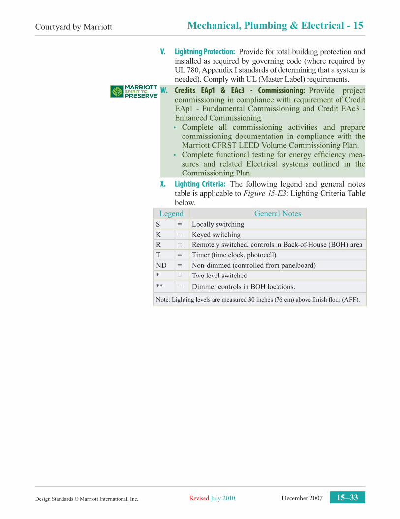
X. Lighting Criteria: The following legend and general notes table is applicable to Figure 15-E3: Lighting Criteria Table below.
Legend General NotesS = Locally switchingK = Keyed switchingR = Remotely switched, controls in Back-of-House (BOH) areaT = Timer (time clock, photocell)ND = Non-dimmed (controlled from panelboard)* = Two level switched** = Dimmer controls in BOH locations.
Note: Lighting levels are measured 30 inches (76 cm) above finish floor (AFF).
Mechanical,Plumbing&Electrical-15
December 2007
Courtyard by Marriott
15–33Design Standards © Marriott International, Inc.

Revised July 2010
Figure 15-E3: LightingCriteria-Table
Mod.No. Space Watts/SF Min.FC
Maintained SwitchLightingType Remarks:Providethe
followingequipmentandfixtures:Incand Fluor
1
Site areas - general 1 Provide average lighting level
of 2 FC; Generally, applies to walks, driveways, parking lots, service areas, steps and ramps. Photocell and time clock; HID light sources.
Pathways 1 TWalkways 1 T
Parking Lot 1 T
Structured Parking 5 R/K X
5 FC minimum (average); higher at corners / entrances for day and night use.
Landscaping 2 T Protected by GFI. Photocell and time clock.
Courtyard Area 5 T
5 FC minimum; 10 FC maximum on photocell & time clock; HID light sources.
Porte Cochere 15 T XPhotocell and time clock. Provide recessed downlights and accenting wall sconces.
2
Vestibule 2 15 R/K XLobby 2 15 R/K X
Reception 20 R/K X Ceiling recessed
Welcome Pedestals / Reception
Area
30 R X
Architectural pendent fixtures; recessed downlights; lighting to appropriately accent the space; task lighting; lighting to complement the associates
Public Toilets 2 20 K XVanities 2 20 K X Above Toilet Room vanities.
BusinessCenter
4015 R/K X X
Provide varied lighting levels appropriate to task - work areas vs. lounge area.
3 “The Bistro” 6 20 R X XRecessed lights, low voltage fixtures and pendant lighting may be used.
4
Indoor Pool 6 20 ND XOutdoor Pool
Deck 5 X X 5 FC averageConnect to Photocell
Pool Equipment 35 S X
Pool Storage 5 S XExercise Room 25 K X
5 Retail Sales“The Market” 2 45 R/K X X
Accent lighting at wall display areas; recessed downlights for general lighting; see Module <2>.
Courtyard by Marriott
December 2007
15-Mechanical,Plumbing&Electrical
15–34 Design Standards © Marriott International, Inc.

Revised July 2010
Figure 15-E3: LightingCriteria-Table
Mod.No. Space Watts/SF Min.FC
Maintained SwitchLightingType Remarks:Providethe
followingequipmentandfixtures:Incand Fluor
6
Meeting Rooms 6-8 25 / 40 S X X
Recessed lighting in center area; dimmable recessed downlights at perimeter.
Board Room 6-8 25 / 40 S X XRecessed lighting in center area; dimmable recessed downlights at perimeter.
Pre-function 3 15 K X X
7
Guestroom 2 35 S X XLighting provided by table, floor, wall sconces, accent and task light fixtures
Guest Bathroom 30 S X Decorative ceiling light for
general illumination
Bath Vanity 30 S X At vanity, decorative wall fixture
Guest Corridors 10 ND X Recessed downlights and
wall sconcesGuest Laundry 30 K XGuest Elevator
Lobbies 10 ND X Recessed downlights and wall sconces
Service Elevator Lobbies
10 ND X Single 32 W, 4ft.; vandal proof tube
Vending Areas 10 ND X Consistent with corridors and elevator lobbies
House- keeping /
Linen2 35 S X Recessed fluorescent
Exit Stairs 6-8 20 ND X
8
Admin Offices & Work Spaces
40 S X Recessed fluorescent lights
Associate Facilities 35 S X
Includes employee break-room, employee restroom /
locker area; recessed fluores-cent lights
9
Engineer -Maintenance 2 35 S X Same as above.
Over work benches 2 50 S X
10
Food Production 2 35 S X Same as above.
General Storage 6-8 20 S X
Mechanical,Plumbing&Electrical-15
December 2007
Courtyard by Marriott
15–35Design Standards © Marriott International, Inc.

Revised July 2010
Figure 15-E3: LightingCriteria-Table
Mod.No. Space Watts/SF Min.FC
Maintained SwitchLightingType Remarks:Providethe
followingequipmentandfixtures:Incand Fluor
11
Laundry 2 35 S X Same as above.Washing 2 35 S X
House-keeping 2 35 S X
Same for general lighting of Housekeeping and Laundry areas
Linen Strg. 2 35 S X12 Elevators 10 ND X
15
MEP - Utility Areas 2 35 S X
System Areas 2 35 S XCoordinate with Module <13> for Hotel Support System spaces
For other spaces not identified above, provide 30 FC minimum.
Courtyard by Marriott
December 2007
15-Mechanical,Plumbing&Electrical
15–36 Design Standards © Marriott International, Inc.