modular/f.r.l. units - smc pneumatics · green indicator red indicator 4 3 2 9 1 8 7 6 5 c modular...
TRANSCRIPT

Round type pressure gauge (with color zone)
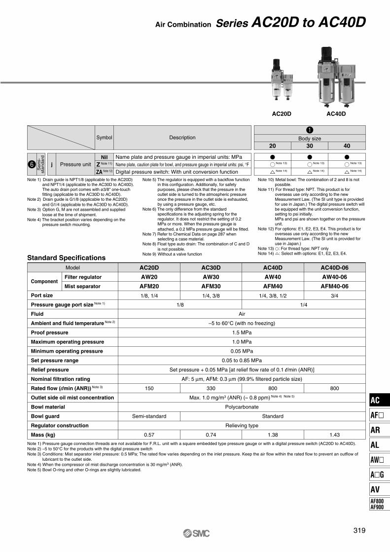
Series AC
Modular/F.R.L. Units
295
AC
AF�
AR
AL
AW�
A�G
AV
AF800
AF900

Green indicator
Red indicator
4
32
19
87
65
SM
C
Modular F.R.L. Units
Series ACBracket with spacer
Retainer
Bolt
Lever pin
e Tighten the bolt.
Improved installation
q Attach the component into the fitting of the spacer with bracket.
w Lock the lever pin into the retainer. (temporary installation)
Graduation
Improved visibility for
lubricant dripwith graduation for lubricant control
Spacer with bracket
Embedded
pressure gauge
is a standard feature.
Float type auto drain with
excellent operability is used
for compact models (AF10/20).
Drain cock is easy-to-use
rotary type.
Ozone resistant rubber
material (HNBR)
Improved relief sensitivity
Round type pressure gauge (with color zone) type� Red and green zones offer improved visibility of pressure control range.
Indicator adjusts to highlight preferred range
� Filter Regulator
AW20(K) to 60(K)� Mist Separator Regulator
AWM20 to 40� Micro Mist Separator Regulator
AWD20 to 40
� Regulator
AR20(K) to 60(K)
� F.R.L. Unit
AC20 to 60 (AF + AR + AL) AC20A to 60A (AW + AL) AC20B to 60B (AF + AR) AC20C to 40C (AF + AFM + AR) AC20D to 40D (AW + AFM)
296

Product ModelPort size
PageM5 x 0.8 1/8 1/4 3/8 1/2 3/4 1
300
306
310
314
318
AC20D
AC30D
AC40D
AC40D-06
Filter Regulator + Mist Separator
AW AFM
AC20C
AC25C
AC30C
AC40C
AC40C-06
Air Filter + Mist Separator + Regulator
AF AFM AR
AC10B
AC20B
AC25B
AC30B
AC40B
AC40B-06
AC50B
AC55B
AC60B
Air Filter + Regulator
AF AR
AC10A
AC20A
AC30A
AC40A
AC40A-06
AC50A
AC60A
Filter Regulator + Lubricator
AW AL
AC10
AC20
AC25
AC30
AC40
AC40-06
AC50
AC55
AC60
Air Filter + Regulator + Lubricator
AF AR AL
Air
Co
mb
inati
on
297
Series Configuration
AC
AF�
AR
AL
AW�
A�G
AV
AF800
AF900
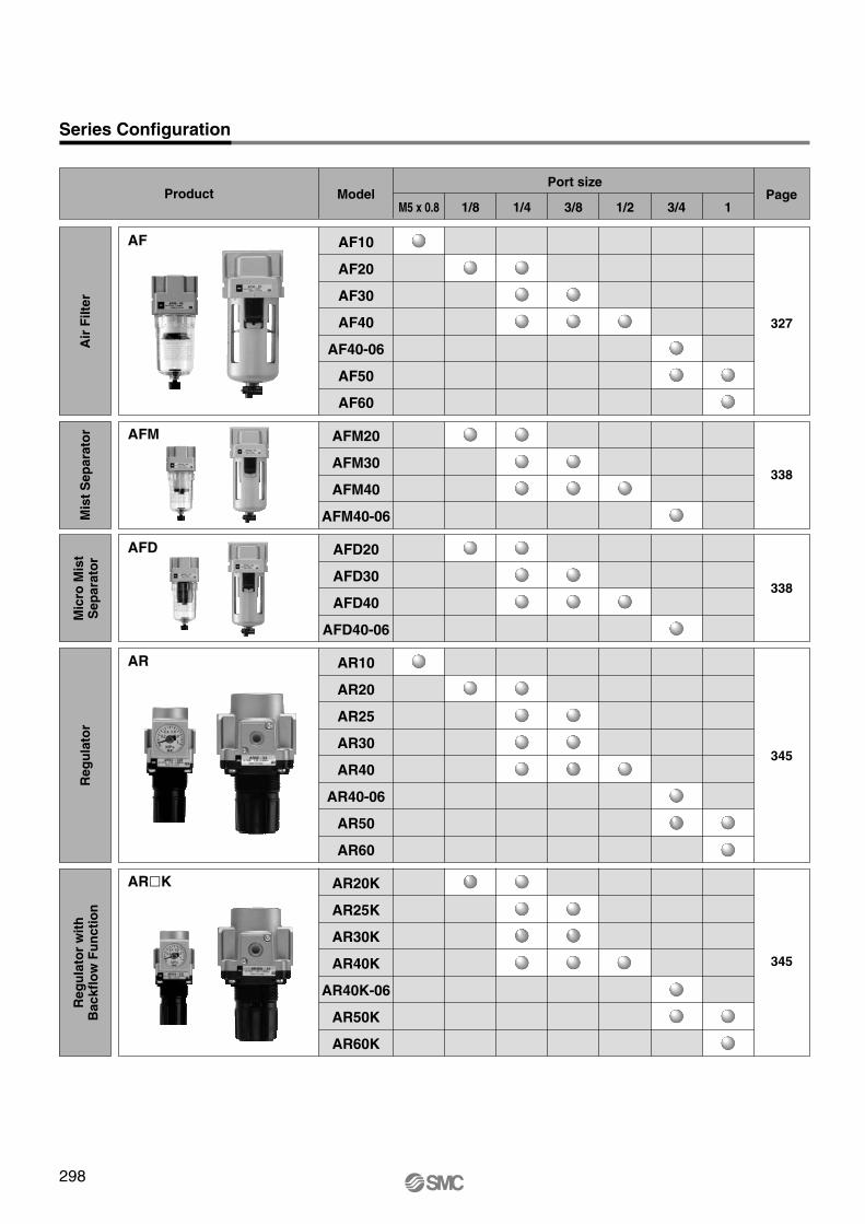
AF10
AF20
AF30
AF40
AF40-06
AF50
AF60
AF
338
AFM20
AFM30
AFM40
AFM40-06
AFM
338
AFD20
AFD30
AFD40
AFD40-06
AFD
345
AR10
AR20
AR25
AR30
AR40
AR40-06
AR50
AR60
AR
345
AR20K
AR25K
AR30K
AR40K
AR40K-06
AR50K
AR60K
AR�K
Product ModelPort size
PageM5 x 0.8 1/8 1/4 3/8 1/2 3/4 1
327
Series Configuration
Air
Fil
ter
Mis
t S
ep
ara
tor
Mic
ro M
ist
Sep
ara
tor
Reg
ula
tor
Reg
ula
tor
wit
hB
ackfl
ow
Fu
ncti
on
298

AL10
AL20
AL30
AL40
AL40-06
AL50
AL60
AL
365
AW10
AW20
AW30
AW40
AW40-06
AW60
AW
365
AW20K
AW30K
AW40K
AW40K-06
AW60K
378
AWM20
AWM30
AWM40
AWM
378
AWD20
AWD30
AWD40
AWD
Product ModelPort size
PageM5 x 0.8 1/8 1/4 3/8 1/2 3/4 1
357
Series Configuration
Lu
bri
ca
tor
Fil
ter
Re
gu
lato
rF
ilte
r R
eg
ula
tor
wit
hB
ackfl
ow
Fu
ncti
on
Mis
tS
ep
ara
tor
Reg
ula
tor
Mic
ro M
ist
Sep
ara
tor
Reg
ula
tor
Short lead timesThis system enables us to respond to your special needs, such as
additional machining, accessory assembly, or modular unit, and
deliver such special products as quickly as standard products.
Repeat orders Once we receive a Simple Special part number from your previous
order, we will process the order, manufacture the product, and
deliver it to you.
A system designed to respond quickly and easily to your special ordering needs.
Simple Specials System
AW�K
299
AC
AF�
AR
AL
AW�
A�G
AV
AF800
AF900

AC 30 03 DE
Air Combination
Air Filter + Regulator + Lubricator
AC10 to AC60JIS Symbol
Air Filter Regulator LubricatorHow to Order
• Option/Semi-standard: Select one each for a to m.
• Option/Attachment/Semi-standard symbol: When more than one
specification is required, indicate in alphanumeric order.
Example) AC30-F03DE1-KSTV-136NR
+
+
+
+
+
+
+
+
+
10 20 25 30 40 50 55 60
Body sizeDescription
Metric thread (M5)
Rc
NPT
G
Symbol
Nil
N Note 1)
F Note 2)
Nil
C
D
Thread type
Float typeauto drain
M5
1/8
1/4
3/8
1/2
3/4
1
M5
01
02
03
04
06
10
Port size
a
Without auto drain
Float type auto drain (N.C.)
Float type auto drain (N.O.)
Nil
E
G
M
E1
E2
E3
E4
Pressuregauge
Digitalpressure
switch
b
Without pressure gauge
Square embedded type pressure gauge (with limit indicator)
Round type pressure gauge (without limit indicator)
Round type pressure gauge (with limit indicator)
Round type pressure gauge (with color zone)
Output: NPN output / Electrical entry: Wiring bottom entry
Output: NPN output / Electrical entry: Wiring top entry
Output: PNP output / Electrical entry: Wiring bottom entry
Output: PNP output / Electrical entry: Wiring top entry
Note 4)
Nil
KCheck valvec
Without attachment
Mounting position: AF+AR+K+AL
Nil
S Note 5)
Pressureswitch
dWithout attachment
Mounting position: AF+AR+S+AL
Nil
T Note 5)T-interfacee
Without attachment
Mounting position: AF+T+AR+AL
Nil
V
3-port valve forresidual pressure
release f
Without attachment
Mounting position: AF+AR+AL+V
Nil
1 Note 6)Set pressureg
0.05 to 0.85 MPa setting
0.02 to 0.2 MPa setting
Nil
2
6
8
C
6C
Bowl Note 7)h
Polycarbonate bowl
Metal bowl
Nylon bowl
Metal bowl with level gauge
With bowl guard
Nylon bowl with bowl guard
Note 3)
Option
Sem
i-sta
ndard
Attachm
ent
300

AC40AC20
Note 1) Pressure gauge connection threads are not available for F.R.L. unit with a square embedded type pressure gauge or with a digital pressure switch (AC20 to AC60).
Note 2) –5 to 50°C for the products with the digital pressure switch
Note 3) Not applicable to the AC10.
Air
–5 to 60°C (with no freezing)
1.5 MPa
1.0 MPa
Set pressure + 0.05 MPa Note 3) [at relief flow rate of 0.1 l/min (ANR)]
5 µm
Class 1 turbine oil (ISO VG32)
Polycarbonate
Relieving type
0.05 to 0.7 MPa 0.05 to 0.85 MPa
AC10 AC20 AC25 AC30 AC40 AC40-06 AC50 AC55 AC60
AF10
AR10
AL10
M5 x 0.8
1/16
1/8, 1/4 1/4, 3/8
1/8
1/4, 3/8 1/4, 3/8, 1/2 3/4 3/4, 1
1/4
1 1
—
0.27
Semi-standard
0.73 0.91 1.00 1.74
Standard
1.95 4.17 4.25 4.34
AF20
AR20
AL20
AF30
AR25
AL30
AF30
AR30
AL30
AF40
AR40
AL40
AF40-06
AR40-06
AL40-06
AF50
AR50
AL50
AF60
AR50
AL60
AF60
AR60
AL60
Model
Component
Air filter
Regulator
Lubricator
Port size
Pressure gauge port size Note 1)
Fluid
Ambient and fluid temperature Note 2)
Proof pressure
Max. operating pressure
Set pressure range
Relief pressure
Nominal filtration rating
Recommended lubricant
Bowl material
Bowl guard
Regulator construction
Mass (kg)
Standard Specifications
+
+
+
+
Note 1) Drain guide is NPT1/8 (applicable to the AC20) and NPT1/4 (applicable to the AC25 to AC60). The auto drain port comes with ø3/8" one-touch fitting (applicable to the AC25 to AC60).
Note 2) Drain guide is G1/8 (applicable to the AC20) and
G1/4 (applicable to the AC25 to AC60). Note 3) Option G, M are not assembled and supplied
loose at the time of shipment.
Note 4) Not available with piping port size: 06. Note 5) The bracket position varies depending on the T-
interface or pressure switch mounting.
Note 6) The only difference from the standard specifications is the adjusting spring for the regulator. It does not restrict the setting of 0.2 MPa or more. When the pressure gauge is
attached, a 0.2 MPa pressure gauge will be fitted. Note 7) Refer to Chemical Data on page 287 when
selecting a case material.Note 8) Float type auto drain: The combination of C and D
is not possible.
Note 9) Without a valve functionNote 10) Metal bowl: The combination of 2 and 8 is not
possible.Note 11) Filter drain port: When choosing with W, the
drain cock of a lubricator will be with barb fittings.
Note 12) For thread type: M5 and NPT. This product is for overseas use only according to the new Measurement Law. (The SI unit type is provided for use in Japan.) The digital pressure switch will be equipped with the unit conversion function, setting to psi initially.MPa and psi are shown together on the pressure unit.
Note 13) For options: E1, E2, E3, E4. This product is for overseas use only according to the new Measurement Law. (The SI unit is provided for use in Japan.)
Note 14) �: For thread type: M5 and NPT onlyNote 15) �: Select with options: E1, E2, E3, E4.
Nil
3 Note 11)
Lubricator lubricant
exhaust portj
Without drain cock
Lubricator with drain cock
Nil
NExhaust
mechanismk
Relieving type
Non-relieving type
Nil
RFlow directionl
Flow direction: Left to right
Flow direction: Right to left
Note 14) Note 14) Note 14) Note 14) Note 14) Note 14) Note 14) Note 14)
Note 15) Note 15) Note 15) Note 15) Note 15) Note 15) Note 15)
Nil
Z Note 12)
ZA Note 13)
Pressure unitm
Name plate and pressure gauge in imperial units: MPa
Name plate, caution plate for bowl, and pressure gauge in imperial units: psi, °F
Digital pressure switch: With unit conversion function
Nil
J Note 9)
W Note 10)
Filter drain port Note 8)i
With drain cock
Drain guide 1/8
Drain guide 1/4
Drain cock with barb fitting: For ø6 x ø4 nylon tube
10 20 25 30 40 50 55 60
Body sizeDescriptionSymbol
Sem
i-sta
ndard
301
Air Combination Series AC10 to AC60
AC
AF�
AR
AL
AW�
A�G
AV
AF800
AF900

AC30
Flow Characteristics (Representative values) Condition: Inlet pressure 0.7 MPa
0.6
0.5
0.4
0.3
0.2
0.1
00 25 50 75 100 125 150
AC10 M5 x 0.8
Ou
tlet p
ressure
(M
Pa
)
Flow rate (l/min (ANR))0
0.6
0.5
0.4
0.3
0.2
0.1
0200 400 600 800
AC20 Rc1/4
Ou
tlet p
ressure
(M
Pa
)Flow rate (l/min (ANR))
0
0.5
0.6
0.4
0.3
0.2
0.1
0500 1000 1500
AC25 Rc3/8
Outle
t pre
ssu
re (
MP
a)
Flow rate (l/min (ANR))
0.6
0.5
0.4
0.3
0.2
0.1
00 1000 2000 3000 4000 5000
AC40-06 Rc3/4
Flow rate (l/min (ANR))
Outle
t pre
ssu
re (
MP
a)
0
0.6
0.5
0.4
0.3
0.2
0.1
0
AC60 Rc1
Flow rate (l/min (ANR))
Outlet
pre
ssure
(M
Pa)
4000 6000 80002000 100000
0.6
0.5
0.4
0.3
0.2
0.1
0
AC55 Rc1
Flow rate (l/min (ANR))
Outlet
pre
ssure
(M
Pa)
4000 6000 80002000 10000
0
0.6
0.5
0.4
0.3
0.2
0.1
01000 2000 3000
AC40 Rc1/2
Flow rate (l/min (ANR))
Ou
tlet p
ressure
(M
Pa
)
0
0.6
0.5
0.4
0.3
0.2
0.1
0500 1000 1500
AC30 Rc3/8
Flow rate (l/min (ANR))
Outle
t pre
ssu
re (
MP
a)
0
0.6
0.5
0.4
0.3
0.2
0.1
0
AC50 Rc1
Flow rate (l/min (ANR))
Outlet
pre
ssure
(M
Pa)
4000 6000 80002000 10000
Pressure Characteristics (Representative values) Conditions: Inlet pressure 0.7 MPa, Outlet pressure 0.2 MPa, Flow rate 20 l/min (ANR)
AC10
0.25
0.3
0.2
0.15
00 0.2 0.3 0.4 0.5 0.6 0.7 0.8 0.9 1.0
Inlet pressure (MPa)
Outlet
pre
ssure
(M
Pa)
Set point
0.25
0.2
0
0.15
0
Outlet pre
ssure
(M
Pa)
0.2 0.3 0.4 0.5 0.6 0.7 0.8 0.9 1.0
Inlet pressure (MPa)
Set point
0.25
0.2
0
0.15
0 0.2 0.3 0.4 0.5 0.6 0.7 0.8 0.9 1.0
Inlet pressure (MPa)
Outlet pre
ssure
(M
Pa)
AC40
Set point
0.25
0.2
0
0.15
0 0.2 0.3 0.4 0.5 0.6 0.7 0.8 0.9 1.0
Inlet pressure (MPa)
Outlet
pre
ssure
(M
Pa)
Set point
AC200.25
0.2
0
0.15
0 0.2 0.3 0.4 0.5 0.6 0.7 0.8 0.9 1.0
Inlet pressure (MPa)
Outlet
pre
ssure
(M
Pa)
AC25
Set point
0.25
0.2
0
0.15
0 0.2 0.3 0.4 0.5 0.6 0.7 0.8 0.9 1.0
Inlet pressure (MPa)
Outlet pre
ssure
(M
Pa)
AC40-06
Set point
302
Series AC10 to AC60
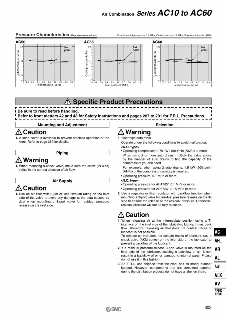
Be sure to read before handling.Refer to front matters 42 and 43 for Safety Instructions and pages 287 to 291 for F.R.L. Precautions.
Pressure Characteristics (Representative values) Conditions: Inlet pressure 0.7 MPa, Outlet pressure 0.2 MPa, Flow rate 20 l/min (ANR)
AC50 AC600.25
0.2
0
0.15
0 0.2 0.3 0.4 0.5 0.6 0.7 0.8 0.9 1.0
Inlet pressure (MPa)
Ou
tlet p
ressure
(M
Pa
)
Set point
0.25
0.2
0
0.15
0 0.2 0.3 0.4 0.5 0.6 0.7 0.8 0.9 1.0
Inlet pressure (MPa)O
utlet p
ressure
(M
Pa
)
AC55
Set point
0.25
0.2
0
0.15
0 0.2 0.3 0.4 0.5 0.6 0.7 0.8 0.9 1.0
Inlet pressure (MPa)
Outle
t pre
ssu
re (
MP
a)
Set point
Specific Product Precautions
Mounting and Adjustment
1. A knob cover is available to prevent careless operation of the knob. Refer to page 389 for details.
Caution
Selection
1. Float type auto drain
Operate under the following conditions to avoid malfunction.
<N.O. type>• Operating compressor: 0.75 kW (100 l/min (ANR)) or more.
When using 2 or more auto drains, multiply the value above by the number of auto drains to find the capacity of the compressors you will need.
For example, when using 2 auto drains, 1.5 kW (200 l/min (ANR)) of the compressor capacity is required.
• Operating pressure: 0.1 MPa or more.
<N.C. type>• Operating pressure for AD17/27: 0.1 MPa or more.
• Operating pressure for AD37/47: 0.15 MPa or more.
2. Use a regulator or filter regulator with backflow function when mounting a 3-port valve for residual pressure release on the IN side to ensure the release of the residual pressure. Otherwise, residual pressure will not be fully released.
Warning
Piping
1. When mounting a check valve, make sure the arrow (IN side) points in the correct direction of air flow.
Warning
Air Supply
1. Use an air filter with 5 µm or less filtration rating on the inlet side of the valve to avoid any damage to the seat caused by dust when mounting a 3-port valve for residual pressure release on the inlet side.
Caution
1. When releasing air at the intermediate position using a T-interface on the inlet side of the lubricator, lubricant may back flow. Therefore, releasing air that does not contain traces of lubricant is not possible.To release air that does not contain traces of lubricant, use a check valve (AKM series) on the inlet side of the lubricator to prevent a backflow of the lubricant.
2. If a residual pressure-release 3-port valve is mounted on the inlet side of the lubricator, causing a backflow of air, it can result in a backflow of oil or damage to internal parts. Please do not use it in this fashion.
3. An F.R.L. unit shipped from the plant has its model number labeled. However, components that are combined together during the distribution process do not have a label on them.
Caution
303
Air Combination Series AC10 to AC60
AC
AF�
AR
AL
AW�
A�G
AV
AF800
AF900

O S
B
B
B
O
S
B
B B
B B
J
H
J
H
JH
OUTR1
OUTR1
Dimensions
AC10, AC20 AC25 to AC60
IN OUT
Drain
M
V
S
R2
BC
A
NF
Q2
Q1
U
K
J
Q1
P2(Pressure gauge port size)
LubricatorRegulatorAirFilter
G
Cle
ara
nce
for
main
ten
an
ce
2 x P1(Port size)
OUT
DrainE
V
M
R2
N
Q1
S U
A
F
LC
K
J
Q1
P2(Pressure gauge port size)
Lubricator
G
RegulatorAir Filter
2 x P1(Port size)
Cle
ara
nce
for
ma
inte
na
nce
IN
Digital pressure switchSquare embedded type pressure gaugeOption Round type pressure gauge
Dimensions
Applicable model AC20 to AC60 AC10 to AC60
Round type pressure gauge (with color zone)
AC20 to AC60
Center ofpiping
Center ofpiping
Center ofpiping
With drain guide Drain cock with barb fittingWith drain guideMetal bowl with level gaugeWith auto drain (N.O./N.C.)Metal bowlWith auto drain (N.C.)Optional/Semi-standard
specifications Metal bowl
Applicable model AC10, AC20 AC20 AC25 to AC60
Dimensions
M5 x 0.81/8
Width across flats 14
N.O.: Black
N.C.: Gray
ø10 one-touch fitting Width across flats 17
1/4Barb fitting
Applicable tubing: T0604
ModelStandard specifications
Optional specificationsSquare type
pressure gaugeDigital
pressure switchRound type
pressure gauge
P1 P2 A B C E F G J
M5 x 0.8
1/8, 1/4
1/4, 3/8
1/4, 3/8
1/4, 3/8, 1/2
3/4
3/4, 1
1
1
1/16
1/8
1/8
1/8
1/4
1/4
1/4
1/4
1/4
87
126
167
167
220
235
282
292
297
85
123
153
153
187
187
264
279
280
26
36
38
38
40
38
43
45
46
—
—
30
30
38
38
45
47.5
47.5
28
41.5
55
55
72.5
77.5
93
98
98
35
60
80
80
110
110
110
110
110
13
28.5
27.5
29.5
34
34
43.5
43.5
43.5
K
0
2
0
3.5
3.5
3
3.3
3.3
3.3
H
—
�28
�28
�28
�28
�28
�28
�28
�28
J
—
29.5
28.5
30.5
35
35
44.5
44.5
44.5
H
—
�27.8
�27.8
�27.8
�27.8
�27.8
�27.8
�27.8
�27.8
J
—
40
39
41
45
45
55
55
55
—
ø37.5
ø37.5
ø37.5
ø42.5
ø42.5
ø42.5
ø42.5
ø42.5
—
65
64
66
74
74
84
84
84
Round type pressuregauge (with color zone)
H JH
ø26
ø37.5
ø37.5
ø37.5
ø42.5
ø42.5
ø42.5
ø42.5
ø42.5
J
26
65
64
66
74
74
84
84
84
AC10
AC20
AC25
AC30
AC40
AC40-06
AC50
AC55
AC60
Model
Optional specifications Semi-standard specifications
Bracket mount With auto drain With barb fitting With drain guide Metal bowlMetal bowl with
level gauge
M N Q1 Q2 R1 R2 S U
25
30
41
41
50
50
70
70
70
31
43
57
57
75
80
96
96
101
20
24
35
35
40
40
50
50
50
27
33
—
—
—
—
—
—
—
4.5
5.5
7
7
9
9
11
11
11
ø4.5
ø5.5
ø7
ø7
ø9
ø9
ø11
ø11
ø11
7
12
14
14
18
18
20
20
20
2.8
3.2
4
4
4
4.6
6.4
6.4
6.4
V
24.5
29
41
41
48
48
60
60
60
B B
104
141
194
194
226
226
303
318
319
B
—
—
161
161
195
195
272
287
288
B
—
127
160
160
194
194
271
286
287
B
85
123
166
166
200
200
276
292
293
—
—
186
186
220
220
296
312
313
AC10
AC20
AC25
AC30
AC40
AC40-06
AC50
AC55
AC60
Note) For the AC20 only, the position of the pressure gauge is above the center of the piping.
Note)
304
Series AC10 to AC60
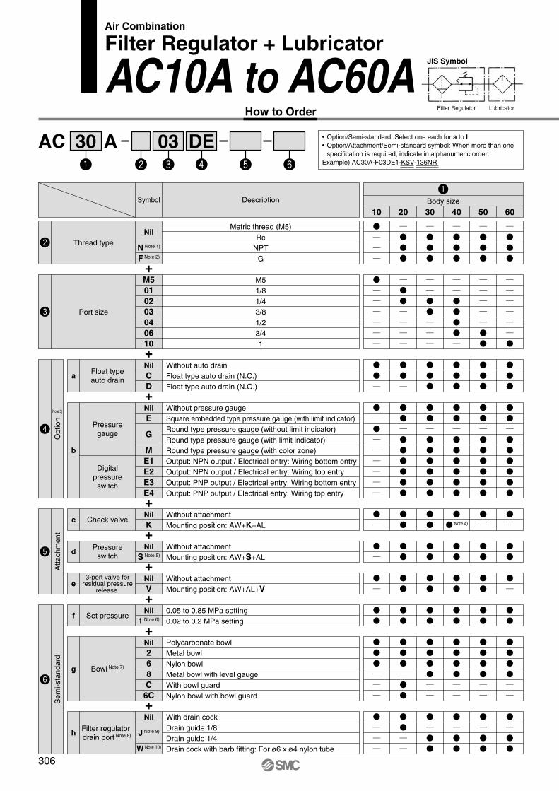
AC A30 03 DE
Air Combination
Filter Regulator + Lubricator
AC10A to AC60AJIS Symbol
Filter Regulator LubricatorHow to Order
• Option/Semi-standard: Select one each for a to l.
• Option/Attachment/Semi-standard symbol: When more than one
specification is required, indicate in alphanumeric order.
Example) AC30A-F03DE1-KSV-136NR
+
+
+
+
+
+
+
+
+
Note 4)
10 20 30 40 50 60
Body sizeDescription
Metric thread (M5)
Rc
NPT
G
Symbol
Nil
N Note 1)
F Note 2)
Nil
C
D
Thread type
Float typeauto drain
M5
1/8
1/4
3/8
1/2
3/4
1
M5
01
02
03
04
06
10
Port size
a
Without auto drain
Float type auto drain (N.C.)
Float type auto drain (N.O.)
Nil
E
G
M
E1
E2
E3
E4
Pressuregauge
Digitalpressure
switch
b
Without pressure gauge
Square embedded type pressure gauge (with limit indicator)
Round type pressure gauge (without limit indicator)
Round type pressure gauge (with limit indicator)
Round type pressure gauge (with color zone)
Output: NPN output / Electrical entry: Wiring bottom entry
Output: NPN output / Electrical entry: Wiring top entry
Output: PNP output / Electrical entry: Wiring bottom entry
Output: PNP output / Electrical entry: Wiring top entry
Nil
KCheck valvec
Without attachment
Mounting position: AW+K+AL
Nil
S Note 5)
Pressureswitch
dWithout attachment
Mounting position: AW+S+AL
Nil
V
3-port valve forresidual pressure
release e
Without attachment
Mounting position: AW+AL+V
Nil
1 Note 6)Set pressuref
0.05 to 0.85 MPa setting
0.02 to 0.2 MPa setting
Nil
J Note 9)
W Note 10)
Filter regulator drain port Note 8)h
With drain cock
Drain guide 1/8
Drain guide 1/4
Drain cock with barb fitting: For ø6 x ø4 nylon tube
Nil
2
6
8
C
6C
Bowl Note 7)g
Polycarbonate bowl
Metal bowl
Nylon bowl
Metal bowl with level gauge
With bowl guard
Nylon bowl with bowl guard
Se
mi-sta
ndard
Attachm
ent
Note 3)
Option
306

AC40A
AC20A
Standard Specifications
Note 1) Pressure gauge connection threads are not available for F.R.L. unit with a square embedded type pressure gauge or with a digital pressure switch (AC20A to AC60A).
Note 2) –5 to 50°C for the products with the digital pressure switch
Note 3) Not applicable to the AC10A.
+
+
+
Air
–5 to 60°C (with no freezing)
1.5 MPa
1.0 MPa
Set pressure + 0.05 MPa Note 3) [at relief flow rate of 0.1 l/min (ANR)]
5 µm
Class 1 turbine oil (ISO VG32)
Polycarbonate
Relieving type
Semi-standard
0.59
Standard
0.05 to 0.85 MPa
0.75 1.41 1.46 3.33 3.40
Model
Component
Port size
Pressure gauge port size Note 1)
Fluid
Ambient and fluid temperature Note 2)
Proof pressure
Maximum operating pressure
Set pressure range
Relief pressure
Nominal filtration rating
Recommended lubricant
Bowl material
Bowl guard
Regulator construction
Mass (kg)
Filter regulator
Lubricator
1/8 1/4
AC60A
AW60
AL60
1
AC50A
AW60
AL50
3/4, 1
AC40A-06
AW40-06
AL40-06
3/4
AC40A
AW40
AL40
1/4, 3/8, 1/2
AC30A
AW30
AL30
1/4, 3/8
AC20A
AW20
AL20
1/8, 1/4
AC10A
AW10
AL10
M5 x 0.8
1/16
0.05 to 0.7 MPa
—
0.20
Note 1) Drain guide is NPT1/8 (applicable to the AC20A) and NPT1/4 (applicable to the AC30A to AC60A). The auto drain port comes with ø3/8" one-touch fitting (applicable to the AC30A to AC60A).
Note 2) Drain guide is G1/8 (applicable to the AC20A)
and G1/4 (applicable to the AC30A to AC60A). Note 3) Option G, M are not assembled and supplied
loose at the time of shipment.
Note 4) Not available with piping port size: 06. Note 5) The bracket position varies depending on the
pressure switch mounting.
Note 6) The only difference from the standard specifications is the adjusting spring for the regulator. It does not restrict the setting of 0.2 MPa or more. When the pressure gauge is
attached, a 0.2 MPa pressure gauge will be fitted. Note 7) Refer to Chemical Data on page 287 when
selecting a case material.Note 8) Float type auto drain: The combination of C and D
is not possible.
Note 9) Without a valve functionNote 10) Metal bowl: The combination of 2 and 8 is not
possible.
Note 11) For thread type: M5 and NPT. This product is for overseas use only according to the new Measurement Law. (The SI unit type is provided for use in Japan.) The digital pressure switch will be equipped with the unit conversion function, setting to psi initially.MPa and psi are shown together on the pressure unit.
Note 12) For options: E1, E2, E3, E4. This product is for overseas use only according to the new Measurement Law. (The SI unit is provided for use in Japan.)
Note 13) �: For thread type: M5 and NPT onlyNote 14) �: Select with options: E1, E2, E3, E4.
Nil
3
Lubricator lubricant
exhaust porti
Without drain cock
Lubricator with drain cock
Nil
NExhaust
mechanismj
Relieving type
Non-relieving type
Nil
RFlow directionk
Flow direction: Left to right
Flow direction: Right to left
Nil
Z Note 11)
ZA Note 12)
Pressure unitl
Name plate and pressure gauge in imperial units: MPa
Name plate, caution plate for bowl, and pressure gauge in imperial units: psi, °F
Digital pressure switch: With unit conversion function
Sem
i-sta
ndard
DescriptionSymbol
Note 13) Note 13) Note 13) Note 13) Note 13) Note 13)
Note 14) Note 14) Note 14) Note 14) Note 14)
10 20 30 40 50 60
Body size
307
Air Combination Series AC10A to AC60A
AC
AF�
AR
AL
AW�
A�G
AV
AF800
AF900

O S
B
B
B
O
S
B
B B
B B
J
H
J
H
V
M
Q2
U
K
Q1
Q1
J
G
E
V
M
U
K Q1
J
Q1
G
R2
B
C
S
A
F
R1
B
C
R2
R1
S
F
A
J
H
Dimensions
AC10A, AC20A AC30A to AC60A
OUT
2 x P1(Port size)
Cle
ara
nce fo
rm
ain
tena
nce
IN OUT
P2(Pressure gauge port size)
LubricatorFilterRegulator
Drain
P2(Pressure gauge port size)
2 x P1(Port size)
Cle
ara
nce
for
ma
inte
na
nce
IN OUT
LubricatorFilterRegulator
Drain
OUT
Round type pressure gauge
AC10A to AC60A
Round type pressure gauge (with color zone)
AC20A to AC60A
With drain guide Drain cock with barb fittingWith drain guideMetal bowl with level gaugeWith auto drain (N.O./N.C.)Metal bowlWith auto drain (N.C.) Metal bowl
Dimensions
Applicable model AC10A, AC20A AC20A AC30A to AC60A
M5 x 0.81/8
Width across flats 14
N.O.: Black
N.C.: Gray
ø10 one-touch fitting Width across flats 17
1/4Barb fitting
Applicable tubing: T0604
Digital pressure switchSquare embedded type pressure gaugeOption
Dimensions
Applicable model AC20A to AC60A
Center ofpiping
Center ofpiping
Center ofpiping
Optional/Semi-standardspecifications
ModelStandard specifications
Optional specificationsSquare type
pressure gaugeDigital
pressure switchRound type
pressure gauge
P1 P2 A B Note) C E F G J
M5 x 0.8
1/8, 1/4
1/4, 3/8
1/4, 3/8, 1/2
3/4
3/4, 1
1
1/16
1/8
1/8
1/4
1/4
1/4
1/4
56
83
110
145
155
191
196
108
160
201
239
242
409
409
48
73
86
92
93
175
175
—
—
30
38
38
—
—
28
41.5
55
72.5
77.5
98
98
35
60
80
110
110
110
110
13
26
29.5
37.5
37.5
43.5
43.5
K
0
5
3.5
1.5
1.2
3.2
3.2
H
—
�28
�28
�28
�28
�28
�28
J
—
27
30.5
38.5
38.5
44.5
44.5
H
—
�27.8
�27.8
�27.8
�27.8
�27.8
�27.8
J
—
37.5
41
49
49
61.5
61.5
Round type pressuregauge (with color zone)
H
—
ø37.5
ø37.5
ø42.5
ø42.5
ø42.5
ø42.5
J
—
63
66
76
76
84
84
H
ø26
ø37.5
ø37.5
ø42.5
ø42.5
ø42.5
ø42.5
J
26
63
66
76
76
84
84
AC10A
AC20A
AC30A
AC40A
AC40A-06
AC50A
AC60A
Model
Optional specifications Semi-standard specifications
Bracket mount With auto drain With barb fitting With drain guide Metal bowlMetal bowl with
level gauge
M Q1 Q2 R1 R2 S U V
25
30
41
50
50
70
70
20
24
35
40
40
50
50
27
33
—
—
—
—
—
4.5
5.5
7
9
9
11
11
ø4.5
ø5.5
ø7
ø9
ø9
ø11
ø11
7
12
14
18
18
20
20
2.8
3.2
4
4
4.6
6.4
6.4
24.5
29
41
48
48
60
60
B
125
177
242
278
282
448
448
B
—
—
209
247
251
417
417
B
—
164
208
246
249
416
416
B
107
160
214
252
255
422
422
B
—
—
234
272
275
442
442
AC10A
AC20A
AC30A
AC40A
AC40A-06
AC50A
AC60A
Note) The total length of B dimension is the length when the filter regulator knob is unlocked.
308
Series AC10A to AC60A
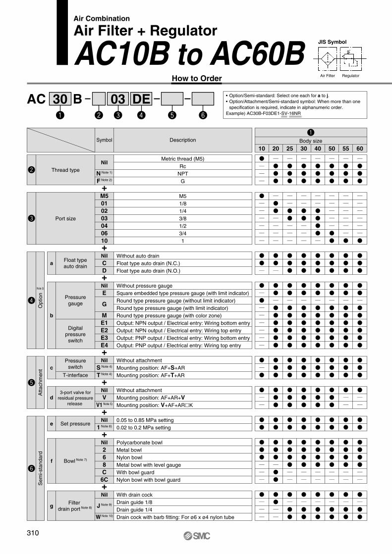
AC B30 03 DE
Air Combination
Air Filter + Regulator
AC10B to AC60BJIS Symbol
Air Filter RegulatorHow to Order
• Option/Semi-standard: Select one each for a to j.
• Option/Attachment/Semi-standard symbol: When more than one
specification is required, indicate in alphanumeric order.
Example) AC30B-F03DE1-SV-16NR
+
+
+
Description
Metric thread (M5)
Rc
NPT
G
Symbol
Nil
N Note 1)
F Note 2)
Nil
C
D
Thread type
Float typeauto drain
M5
1/8
1/4
3/8
1/2
3/4
1
M5
01
02
03
04
06
10
Port size
a
Without auto drain
Float type auto drain (N.C.)
Float type auto drain (N.O.)
Nil
E
G
M
E1
E2
E3
E4
Pressuregauge
Digitalpressure
switch
b
Without pressure gauge
Square embedded type pressure gauge (with limit indicator)
Round type pressure gauge (without limit indicator)
Round type pressure gauge (with limit indicator)
Round type pressure gauge (with color zone)
Output: NPN output / Electrical entry: Wiring bottom entry
Output: NPN output / Electrical entry: Wiring top entry
Output: PNP output / Electrical entry: Wiring bottom entry
Output: PNP output / Electrical entry: Wiring top entry
10 20 25 30 40 50 55 60
Body size
+
+
+
+
+
Nil
S Note 4)
T Note 4)
Pressureswitch
T-interface
c
Without attachment
Mounting position: AF+S+AR
Mounting position: AF+T+AR
Nil
V
V1 Note 5)
3-port valve for
residual pressure
release
d
Without attachment
Mounting position: AF+AR+V
Mounting position: V+AF+AR�K
Nil
1 Note 6)Set pressuree
0.05 to 0.85 MPa setting
0.02 to 0.2 MPa setting
Nil
J Note 9)
W Note 10)
Filter drain port Note 8)g
With drain cock
Drain guide 1/8
Drain guide 1/4
Drain cock with barb fitting: For ø6 x ø4 nylon tube
Nil
2
6
8
C
6C
Bowl Note 7)f
Polycarbonate bowl
Metal bowl
Nylon bowl
Metal bowl with level gauge
With bowl guard
Nylon bowl with bowl guard
Attachm
ent
Sem
i-sta
ndard
Note 3)
Option
310

AC40BAC20B
+
+
Note 1) Drain guide is NPT1/8 (applicable to the AC20B) and NPT1/4 (applicable to the AC25B to AC60B). The auto drain port comes with ø3/8" one-touch fitting (applicable to the AC25B to AC60B).
Note 2) Drain guide is G1/8 (applicable to the AC20B)
and G1/4 (applicable to the AC25B to AC60B). Note 3) Option G, M are not assembled and supplied
loose at the time of shipment.Note 4) The bracket position varies depending on the T-
interface or pressure switch mounting.
Note 5) The regulator is equipped with a backflow function in this configuration. Additionally, for safety purposes, please check that the pressure in the outlet side is turned to the atmospheric pressure once the pressure in the outlet side is exhausted,
by using a pressure gauge, etc.Note 6) The only difference from the standard
specifications is the adjusting spring for the regulator. It does not restrict the setting of 0.2 MPa or more. When the pressure gauge is
attached, a 0.2 MPa pressure gauge will be fitted. Note 7) Refer to Chemical Data on page 287 when
selecting a case material.Note 8) Float type auto drain: The combination of C and D
is not possible.Note 9) Without a valve function
Note 10) Metal bowl: The combination of 2 and 8 is not possible.
Note 11) For thread type: M5 and NPT. This product is for overseas use only according to the new Measurement Law. (The SI unit type is provided for use in Japan.) The digital pressure switch will be equipped with the unit conversion function, setting to psi initially.MPa and psi are shown together on the pressure unit.
Note 12) For options: E1, E2, E3, E4. This product is for overseas use only according to the new Measurement Law. (The SI unit is provided for use in Japan.)
Note 13) �: For thread type: M5 and NPT onlyNote 14) �: Select with options: E1, E2, E3, E4.
Standard Specifications
Note 1) Pressure gauge connection threads are not available for F.R.L. unit with a square embedded type pressure gauge or with a digital pressure switch (AC10B to AC60B).
Note 2) –5 to 50°C for the products with the digital pressure switch
Note 3) Not applicable to the AC10B.
Air
–5 to 60°C (with no freezing)
1.5 MPa
1.0 MPa
Set pressure + 0.05 MPa Note 3) [at relief flow rate of 0.1 l/min (ANR)]
5 µm
Polycarbonate
Relieving type
Semi-standard
0.51
Standard
0.55 0.63 1.12 1.16 2.542.44 2.45
Model
Component
Port size
Pressure gauge port size Note 1)
Fluid
Ambient and fluid temperature Note 2)
Proof pressure
Maximum operating pressure
Set pressure range
Relief pressure
Nominal filtration rating
Bowl material
Bowl guard
Regulator construction
Mass (kg)
Air filter
Regulator
AC25B
AF30
AR25
1/4, 3/8
AC30B
AF30
AR30
1/4, 3/8
AC40B
AF40
AR40
1/4, 3/8, 1/2
AC40B-06
AF40-06
AR40-06
3/4
AC50B
AF50
AR50
3/4, 1
AC55B
AF60
AR50
1
AC60B
AF60
AR60
1
AC20B
AF20
AR20
1/8, 1/4
AC10B
AF10
AR10
M5 x 0.8
1/16
0.05 to 0.7 MPa
—
0.16
1/8 1/4
0.05 to 0.85 MPa
Nil
NExhaust
mechanismh
Relieving type
Non-relieving type
Nil
RFlow directioni
Flow direction: Left to right
Flow direction: Right to left
Nil
Z Note 11)
ZA Note 12)
Pressure unitj
Name plate and pressure gauge in imperial units: MPa
Name plate, caution plate for bowl, and pressure gauge in imperial units: psi, °F
Digital pressure switch: With unit conversion function
10 20 25 30 40 50 55 60
Body sizeDescriptionSymbol
Sem
i-sta
ndard
Note 13) Note 13) Note 13) Note 13) Note 13) Note 13)
Note 14) Note 14)
Note 13)
Note 14) Note 14) Note 14)
Note 13)
Note 14) Note 14)
311
Air Combination Series AC10B to AC60B
AC
AF�
AR
AL
AW�
A�G
AV
AF800
AF900

O S
B
B
B
O
S
B
B B
B B
J
H
J
H
JH
E
V
M
BC
R2
U
R1
S
F
A
K
Q1
Q1
J
G
V
MR2
BC
U
Q2
R1
A
F
S
K Q1
Q1
J
G
Dimensions
AC10B, AC20B AC25B to AC60B
RegulatorAir Filter
P2(Pressure gauge port size)
2 x P1(Port size)
Cle
ara
nce
for
main
ten
an
ce
Drain
IN OUT IN OUT
P2(Pressure gauge port size)
RegulatorAir Filter
2 x P1(Port size)
Cle
ara
nce fo
rm
ain
tena
nce
Drain
Digital pressure switchSquare embedded type pressure gaugeOption Round type pressure gauge
Dimensions
Applicable model AC20B to AC60B AC10B to AC60B
Round type pressure gauge (with color zone)
AC20B to AC60B
Center ofpiping
Center ofpiping
Center ofpiping
With drain guide Drain cock with barb fittingWith drain guideMetal bowl with level gaugeWith auto drain (N.O./N.C.)Metal bowlWith auto drain (N.C.)Optional/Semi-standard
specifications Metal bowl
Dimensions
Applicable model AC10B, AC20B AC20B AC25B to AC60B
M5 x 0.81/8
Width across flats 14
N.O.: Black
N.C.: Gray
ø10 one-touch fitting Width across flats 17
1/4Barb fitting
Applicable tubing: T0604
ModelStandard specifications
Optional specificationsSquare type
pressure gaugeDigital
pressure switchRound type
pressure gauge
P1 P2 A B C E F G J
M5 x 0.8
1/8, 1/4
1/4, 3/8
1/4, 3/8
1/4, 3/8, 1/2
3/4
3/4, 1
1
1
1/16
1/8
1/8
1/8
1/4
1/4
1/4
1/4
1/4
56
83
110
110
145
155
186
191
196
71
114
143
146
183
185
263
277
280
11
26.5
28
31
36
36
43
43
46
—
—
30
30
38
38
45
47.5
47.5
28
41.5
55
55
72.5
77.5
93
98
98
25
40
50
50
75
75
20
20
20
13
28.5
27.5
29.5
34
34
43.5
43.5
43.5
K
0
2 Note)
0
3.5
3.5
3
3.3
3.3
3.3
H
—
�28
�28
�28
�28
�28
�28
�28
�28
J
—
29.5
28.5
30.5
35
35
44.5
44.5
44.5
H
—
�27.8
�27.8
�27.8
�27.8
�27.8
�27.8
�27.8
�27.8
J
—
40
39
41
45
45
55
55
55
Round type pressuregauge (with color zone)
H
—
ø37.5
ø37.5
ø37.5
ø42.5
ø42.5
ø42.5
ø42.5
ø42.5
J
—
65
64
66
74
74
84
84
84
H
ø26
ø37.5
ø37.5
ø37.5
ø42.5
ø42.5
ø42.5
ø42.5
ø42.5
J
26
65
64
66
74
74
84
84
84
AC10B
AC20B
AC25B
AC30B
AC40B
AC40B-06
AC50B
AC55B
AC60B
Model
Optional specifications Semi-standard specifications
Bracket mount With auto drain With barb fitting With drain guide Metal bowlMetal bowl with
level gauge
M Q1 Q2 R1 R2 S U V
25
30
41
41
50
50
70
70
70
20
24
35
35
40
40
50
50
50
27
33
—
—
—
—
—
—
—
4.5
5.5
7
7
9
9
11
11
11
ø4.5
ø5.5
ø7
ø7
ø9
ø9
ø11
ø11
ø11
7
12
14
14
18
18
20
20
20
2.8
3.2
4
4
4
4.6
6.4
6.4
6.4
24.5
29
41
41
48
48
60
60
60
B
89
132
184
187
222
224
303
316
319
B
—
—
151
154
191
193
271
285
288
B
—
118
150
153
190
192
270
284
287
B
70
114
156
159
196
198
277
290
293
B
—
—
176
179
216
218
297
310
313
AC10B
AC20B
AC25B
AC30B
AC40B
AC40B-06
AC50B
AC55B
AC60B
Note) For the AC20B only, the position of the pressure gauge is above the center of the piping.
312
Series AC10B to AC60B
AC C30 03 DE
Air Combination
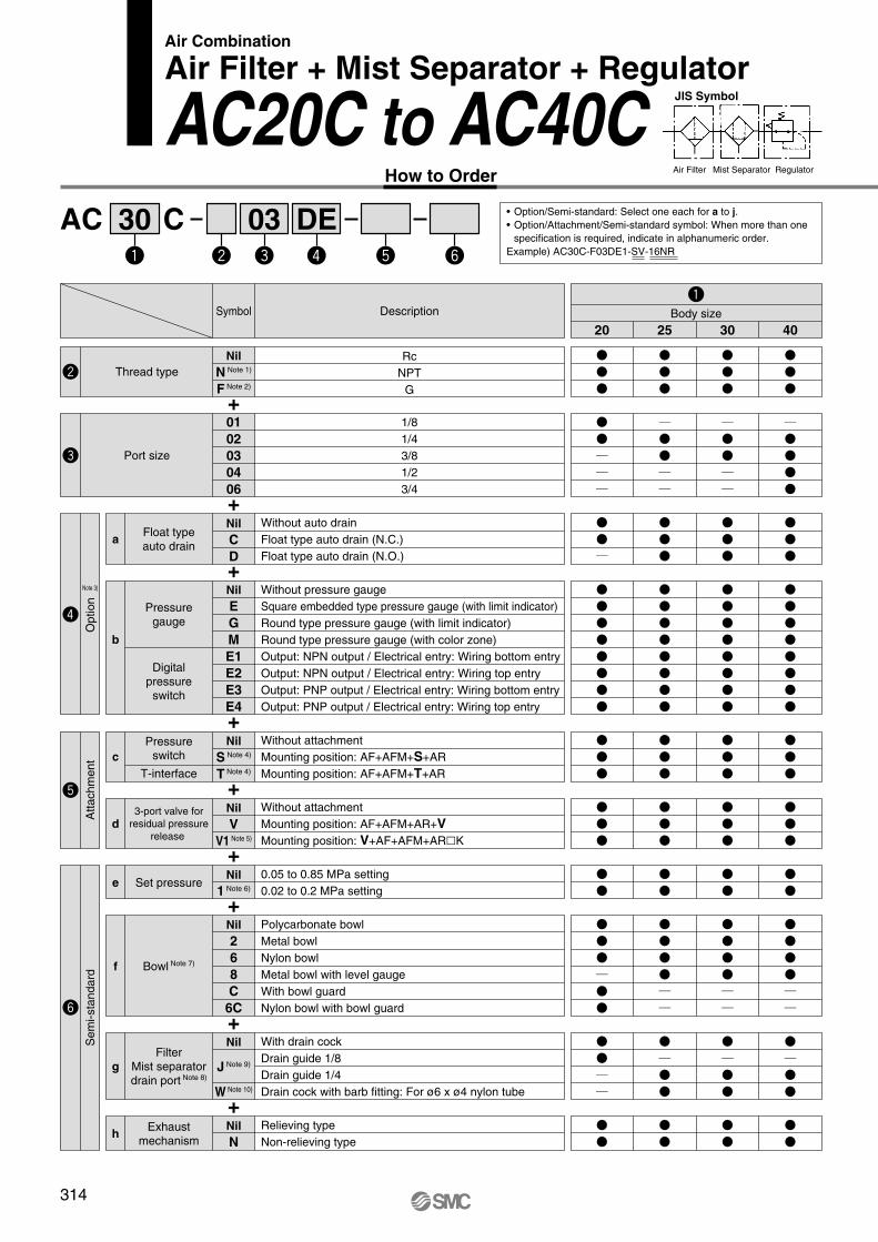
Air Filter + Mist Separator + Regulator
AC20C to AC40CJIS Symbol
Air Filter Mist Separator RegulatorHow to Order
• Option/Semi-standard: Select one each for a to j.
• Option/Attachment/Semi-standard symbol: When more than one
specification is required, indicate in alphanumeric order.
Example) AC30C-F03DE1-SV-16NR
+
+
+
+
+
+
+
+
+
Description
Rc
NPT
G
Symbol
Nil
N Note 1)
F Note 2)
Nil
E
G
M
E1
E2
E3
E4
Nil
C
D
01
02
03
04
06
Thread type
Port size
Pressuregauge
Nil
S Note 4)
T Note 4)
Pressureswitch
T-interface
Digitalpressureswitch
Float typeauto drain
1/8
1/4
3/8
1/2
3/4
Without auto drain
Float type auto drain (N.C.)
Float type auto drain (N.O.)
Without pressure gauge
Square embedded type pressure gauge (with limit indicator)
Round type pressure gauge (with limit indicator)
Round type pressure gauge (with color zone)
Output: NPN output / Electrical entry: Wiring bottom entry
Output: NPN output / Electrical entry: Wiring top entry
Output: PNP output / Electrical entry: Wiring bottom entry
Output: PNP output / Electrical entry: Wiring top entry
b
a
c
Nil
V
V1 Note 5)
3-port valve for
residual pressure
release d
25 30 4020
Body size
Without attachment
Mounting position: AF+AFM+S+AR
Mounting position: AF+AFM+T+AR
Without attachment
Mounting position: AF+AFM+AR+V
Mounting position: V+AF+AFM+AR�K
Nil
2
6
8
C
6C
FilterMist separatordrain port Note 8)
Bowl Note 7)
Nil
1 Note 6)
Nil
N
Set pressure
Exhaustmechanism
Nil
J Note 9)
W Note 10)
With drain cock
Drain guide 1/8
Drain guide 1/4
Drain cock with barb fitting: For ø6 x ø4 nylon tube
f
e
h
Polycarbonate bowl
Metal bowl
Nylon bowl
Metal bowl with level gauge
With bowl guard
Nylon bowl with bowl guard
0.05 to 0.85 MPa setting
0.02 to 0.2 MPa setting
Relieving type
Non-relieving type
g
Sem
i-sta
ndard
Attachm
ent
Note 3)
Option
314
DescriptionSymbol
25 30 4020
Body size
Air
–5 to 60°C (with no freezing)
1.5 MPa
1.0 MPa
0.05 MPa
0.05 to 0.85 MPa
Set pressure + 0.05 MPa [at relief flow rate of 0.1 l/min (ANR)]
AF: 5 µm, AFM: 0.3 µm (99.9% filtered particle size)
Max. 1.0 mg/m3 (ANR) (≈ 0.8 ppm) Note 4) Note 5)
Polycarbonate
Relieving type
450
0.88
200
Semi-standard
0.74
Standard
450
0.95
1100
1.76
1100
1.83
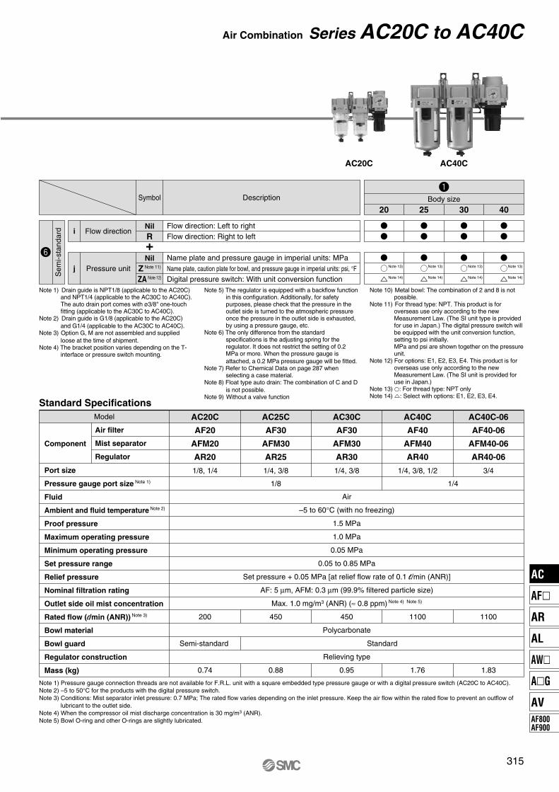
Model
Component
Port size
Pressure gauge port size Note 1)
Fluid
Ambient and fluid temperature Note 2)
Proof pressure
Maximum operating pressure
Minimum operating pressure
Set pressure range
Relief pressure
Nominal filtration rating
Outlet side oil mist concentration
Rated flow (l/min (ANR)) Note 3)
Bowl material
Bowl guard
Regulator construction
Mass (kg)
Air filter
Mist separator
Regulator
AC40C-06
AF40-06
AFM40-06
AR40-06
3/4
AC40C
AF40
AFM40
AR40
1/4, 3/8, 1/2
AC30C
AF30
AFM30
AR30
1/4, 3/8
AC25C
AF30
AFM30
AR25
1/4, 3/8
AC20C
AF20
AFM20
AR20
1/8, 1/4
1/8 1/4
Note 1) Pressure gauge connection threads are not available for F.R.L. unit with a square embedded type pressure gauge or with a digital pressure switch (AC20C to AC40C).
Note 2) –5 to 50°C for the products with the digital pressure switch.
Note 3) Conditions: Mist separator inlet pressure: 0.7 MPa; The rated flow varies depending on the inlet pressure. Keep the air flow within the rated flow to prevent an outflow of
lubricant to the outlet side.
Note 4) When the compressor oil mist discharge concentration is 30 mg/m3 (ANR).
Note 5) Bowl O-ring and other O-rings are slightly lubricated.
Standard Specifications
Nil
Z Note 11)
ZA Note 12)
Pressure unitj
Name plate and pressure gauge in imperial units: MPa
Name plate, caution plate for bowl, and pressure gauge in imperial units: psi, °F
Digital pressure switch: With unit conversion function
Nil
RFlow directioni
Flow direction: Left to right
Flow direction: Right to left
Note 1) Drain guide is NPT1/8 (applicable to the AC20C) and NPT1/4 (applicable to the AC30C to AC40C). The auto drain port comes with ø3/8" one-touch fitting (applicable to the AC30C to AC40C).
Note 2) Drain guide is G1/8 (applicable to the AC20C)
and G1/4 (applicable to the AC30C to AC40C). Note 3) Option G, M are not assembled and supplied
loose at the time of shipment.Note 4) The bracket position varies depending on the T-
interface or pressure switch mounting.
Note 5) The regulator is equipped with a backflow function in this configuration. Additionally, for safety purposes, please check that the pressure in the outlet side is turned to the atmospheric pressure once the pressure in the outlet side is exhausted, by using a pressure gauge, etc.
Note 6) The only difference from the standard specifications is the adjusting spring for the regulator. It does not restrict the setting of 0.2 MPa or more. When the pressure gauge is
attached, a 0.2 MPa pressure gauge will be fitted. Note 7) Refer to Chemical Data on page 287 when
selecting a case material.Note 8) Float type auto drain: The combination of C and D
is not possible.Note 9) Without a valve function
Note 10) Metal bowl: The combination of 2 and 8 is not possible.
Note 11) For thread type: NPT. This product is for overseas use only according to the new Measurement Law. (The SI unit type is provided for use in Japan.) The digital pressure switch will be equipped with the unit conversion function, setting to psi initially.MPa and psi are shown together on the pressure unit.
Note 12) For options: E1, E2, E3, E4. This product is for overseas use only according to the new Measurement Law. (The SI unit is provided for use in Japan.)
Note 13) �: For thread type: NPT onlyNote 14) �: Select with options: E1, E2, E3, E4.
+
Sem
i-sta
ndard
Note 13) Note 13) Note 13) Note 13)
Note 14) Note 14) Note 14) Note 14)
315
Air Combination Series AC20C to AC40C
AC40CAC20C
AC
AF�
AR
AL
AW�
A�G
AV
AF800
AF900
O S
B
B
BO
S
B
B B
B B
J
H
J
H
J
H
BC
R1
SV
M
R2
A
NF
UQ
2
K Q1
Q1
J
G
R1 S
BC
R2
E
V
M
A
NF
U
K Q1
Q1
J
G
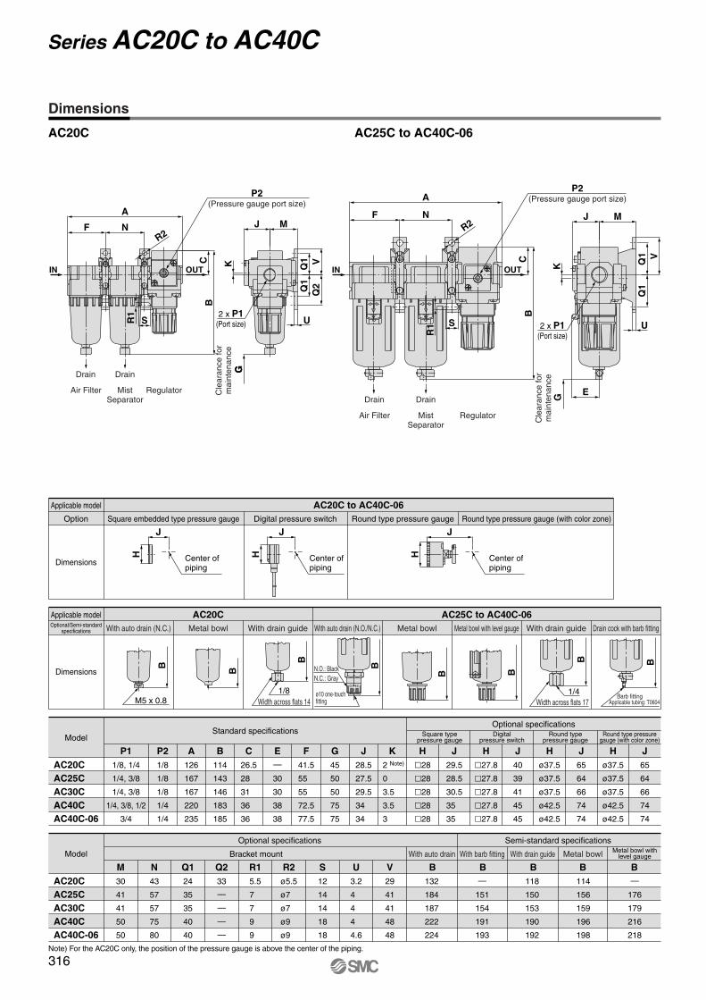
Dimensions
AC20C AC25C to AC40C-06
Drain Drain
G
RegulatorMistSeparator
Air Filter
P2(Pressure gauge port size)
2 x P1(Port size)
Cle
ara
nce
for
main
ten
an
ce
IN OUT OUT
Drain Drain
RegulatorMistSeparator
Air Filter
P2(Pressure gauge port size)
2 x P1(Port size)
Cle
ara
nce
for
ma
inte
nan
ce
IN
Digital pressure switchSquare embedded type pressure gaugeOption Round type pressure gauge Round type pressure gauge (with color zone)
Dimensions
Applicable model AC20C to AC40C-06
Center ofpiping
Center ofpiping
Center ofpiping
With drain guide Drain cock with barb fittingWith drain guideMetal bowl with level gaugeWith auto drain (N.O./N.C.)Metal bowlWith auto drain (N.C.)Optional/Semi-standard
specifications Metal bowl
Dimensions
Applicable model AC20C AC25C to AC40C-06
M5 x 0.81/8
Width across flats 14
N.O.: Black
N.C.: Gray
ø10 one-touch fitting Width across flats 17
1/4Barb fitting
Applicable tubing: T0604
ModelStandard specifications
Optional specificationsSquare type
pressure gaugeDigital
pressure switchRound type
pressure gauge
P1 P2 A B C E F G J
1/8, 1/4
1/4, 3/8
1/4, 3/8
1/4, 3/8, 1/2
3/4
1/8
1/8
1/8
1/4
1/4
126
167
167
220
235
114
143
146
183
185
26.5
28
31
36
36
—
30
30
38
38
41.5
55
55
72.5
77.5
45
50
50
75
75
28.5
27.5
29.5
34
34
K
2 Note)
0
3.5
3.5
3
H
�28
�28
�28
�28
�28
J
29.5
28.5
30.5
35
35
H
�27.8
�27.8
�27.8
�27.8
�27.8
ø37.5
ø37.5
ø37.5
ø42.5
ø42.5
J
40
39
41
45
45
Round type pressuregauge (with color zone)
H J
65
64
66
74
74
H
ø37.5
ø37.5
ø37.5
ø42.5
ø42.5
J
65
64
66
74
74
AC20C
AC25C
AC30C
AC40C
AC40C-06
Model
Optional specifications Semi-standard specifications
Bracket mount With auto drain With barb fitting With drain guide Metal bowlMetal bowl with
level gauge
M N Q1 Q2 R1 R2 S U
30
41
41
50
50
43
57
57
75
80
24
35
35
40
40
33
—
—
—
—
5.5
7
7
9
9
ø5.5
ø7
ø7
ø9
ø9
12
14
14
18
18
3.2
4
4
4
4.6
V
29
41
41
48
48
B B
132
184
187
222
224
B
—
151
154
191
193
B
118
150
153
190
192
B
114
156
159
196
198
—
176
179
216
218
AC20C
AC25C
AC30C
AC40C
AC40C-06
Note) For the AC20C only, the position of the pressure gauge is above the center of the piping.
316
Series AC20C to AC40C
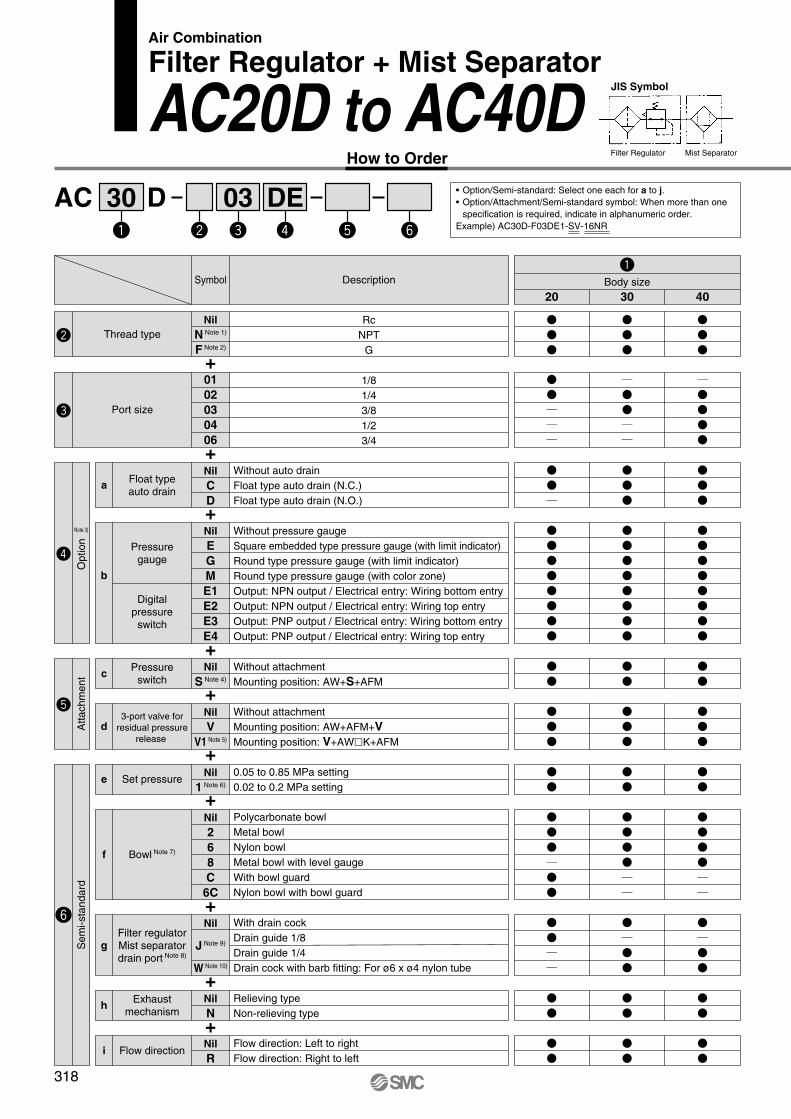
AC D30 03 DE
Air Combination
Filter Regulator + Mist Separator
AC20D to AC40DJIS Symbol
Filter Regulator Mist SeparatorHow to Order
• Option/Semi-standard: Select one each for a to j.
• Option/Attachment/Semi-standard symbol: When more than one
specification is required, indicate in alphanumeric order.
Example) AC30D-F03DE1-SV-16NR
+
+
+
+
+
Description
Rc
NPT
G
Symbol
Nil
N Note 1)
F Note 2)
01
02
03
04
06
Thread type
Port size
1/8
1/4
3/8
1/2
3/4
30 4020
Nil
E
G
M
E1
E2
E3
E4
Pressuregauge
Digitalpressure
switch
Without pressure gauge
Square embedded type pressure gauge (with limit indicator)
Round type pressure gauge (with limit indicator)
Round type pressure gauge (with color zone)
Output: NPN output / Electrical entry: Wiring bottom entry
Output: NPN output / Electrical entry: Wiring top entry
Output: PNP output / Electrical entry: Wiring bottom entry
Output: PNP output / Electrical entry: Wiring top entry
b
Nil
C
D
Float typeauto drain
Without auto drain
Float type auto drain (N.C.)
Float type auto drain (N.O.)
a
Body size
Nil
V
V1 Note 5)
3-port valve for
residual pressure
release
Without attachment
Mounting position: AW+AFM+V
Mounting position: V+AW�K+AFM
d
Nil
S Note 4)
Pressureswitch
Without attachment
Mounting position: AW+S+AFMc
+
+
+
+
+
Nil
J Note 9)
W Note 10)
Filter regulatorMist separatordrain port Note 8)
With drain cock
Drain guide 1/8
Drain guide 1/4
Drain cock with barb fitting: For ø6 x ø4 nylon tube
g
Nil
1 Note 6)Set pressure
0.05 to 0.85 MPa setting
0.02 to 0.2 MPa settinge
Nil
N
Exhaustmechanism
Relieving type
Non-relieving typeh
Nil
RFlow direction
Flow direction: Left to right
Flow direction: Right to lefti
Nil
2
6
8
C
6C
Bowl Note 7)
Polycarbonate bowl
Metal bowl
Nylon bowl
Metal bowl with level gauge
With bowl guard
Nylon bowl with bowl guard
f
Sem
i-sta
ndard
Attachm
ent
Note 3)
Option
318
AC20D AC40D
Nil
Z Note 11)
ZA Note 12)
Pressure unit
Name plate and pressure gauge in imperial units: MPa
Name plate, caution plate for bowl, and pressure gauge in imperial units: psi, °F
Digital pressure switch: With unit conversion function
j
Sem
i-sta
nda
rd
DescriptionSymbol
30 4020
Body size
Note 13) Note 13)Note 13)
Note 14) Note 14)Note 14)
Air
–5 to 60°C (with no freezing)
1.5 MPa
1.0 MPa
0.05 MPa
0.05 to 0.85 MPa
Set pressure + 0.05 MPa [at relief flow rate of 0.1 l/min (ANR)]
AF: 5 µm, AFM: 0.3 µm (99.9% filtered particle size)
Max. 1.0 mg/m3 (ANR) (≈ 0.8 ppm) Note 4) Note 5)
Polycarbonate
Relieving type
330
0.74
150
Semi-standard
0.57
800
Standard
1.38
800
1.43
Model
Component
Port size
Pressure gauge port size Note 1)
Fluid
Ambient and fluid temperature Note 2)
Proof pressure
Maximum operating pressure
Minimum operating pressure
Set pressure range
Relief pressure
Nominal filtration rating
Rated flow (l/min (ANR)) Note 3)
Outlet side oil mist concentration
Bowl material
Bowl guard
Regulator construction
Mass (kg)
Filter regulator
Mist separator
AC40D-06
AW40-06
AFM40-06
3/4
AC40D
AW40
AFM40
1/4, 3/8, 1/2
AC30D
AW30
AFM30
1/4, 3/8
AC20D
AW20
AFM20
1/8, 1/4
1/8 1/4
Standard Specifications
Note 1) Pressure gauge connection threads are not available for F.R.L. unit with a square embedded type pressure gauge or with a digital pressure switch (AC20D to AC40D).
Note 2) –5 to 50°C for the products with the digital pressure switch
Note 3) Conditions: Mist separator inlet pressure: 0.5 MPa; The rated flow varies depending on the inlet pressure. Keep the air flow within the rated flow to prevent an outflow of
lubricant to the outlet side.
Note 4) When the compressor oil mist discharge concentration is 30 mg/m3 (ANR).
Note 5) Bowl O-ring and other O-rings are slightly lubricated.
Note 1) Drain guide is NPT1/8 (applicable to the AC20D) and NPT1/4 (applicable to the AC30D to AC40D). The auto drain port comes with ø3/8" one-touch fitting (applicable to the AC30D to AC40D).
Note 2) Drain guide is G1/8 (applicable to the AC20D)
and G1/4 (applicable to the AC30D to AC40D). Note 3) Option G, M are not assembled and supplied
loose at the time of shipment.Note 4) The bracket position varies depending on the
pressure switch mounting.
Note 10) Metal bowl: The combination of 2 and 8 is not possible.
Note 11) For thread type: NPT. This product is for overseas use only according to the new Measurement Law. (The SI unit type is provided for use in Japan.) The digital pressure switch will be equipped with the unit conversion function, setting to psi initially.MPa and psi are shown together on the pressure unit.
Note 12) For options: E1, E2, E3, E4. This product is for overseas use only according to the new Measurement Law. (The SI unit is provided for use in Japan.)
Note 13) �: For thread type: NPT onlyNote 14) �: Select with options: E1, E2, E3, E4.
Note 5) The regulator is equipped with a backflow function in this configuration. Additionally, for safety purposes, please check that the pressure in the outlet side is turned to the atmospheric pressure once the pressure in the outlet side is exhausted, by using a pressure gauge, etc.
Note 6) The only difference from the standard specifications is the adjusting spring for the regulator. It does not restrict the setting of 0.2 MPa or more. When the pressure gauge is
attached, a 0.2 MPa pressure gauge will be fitted. Note 7) Refer to Chemical Data on page 287 when
selecting a case material.Note 8) Float type auto drain: The combination of C and D
is not possible.Note 9) Without a valve function
319
Air Combination Series AC20D to AC40D
AC
AF�
AR
AL
AW�
A�G
AV
AF800
AF900

O S
B
B
B
O
S
B
B B
B B
J
H
J
H
J
H
R2
B
A
F
S R1
C
R2
A
F
R1
S
B
C
OUT
V
M
Q2
U
K
Q1
Q1
JG
OUT
E
V
M
U
K Q1
J
Q1
G
Dimensions
AC20D AC30D to AC40D-06
IN OUT
MistSeparator
FilterRegulator
P2(Pressure gauge port size)
Drain Drain
IN OUT
MistSeparator
FilterRegulator
P2(Pressure gauge port size)
Drain Drain
2 x P1(Port size)
Cle
ara
nce
fo
rm
ain
ten
an
ce
2 x P1(Port size)
Cle
ara
nce f
or
main
tenance
Digital pressure switchSquare embedded type pressure gaugeOption Round type pressure gauge Round type pressure gauge (with color zone)
Dimensions
Applicable model AC20D to AC40D-06
Center ofpiping
Center ofpiping
Center ofpiping
With drain guide With drain guideMetal bowl with level gauge Drain cock with barb fittingWith auto drain (N.O./N.C.)Metal bowlWith auto drain (N.C.)Optional/Semi-standard
specifications Metal bowl
Dimensions
Applicable model AC20D AC30D to AC40D-06
M5 x 0.81/8
Width across flats 14
N.O.: Black
N.C.: Gray
ø10 one-touch fitting Width across flats 17
1/4Barb fitting
Applicable tubing: T0604
M Q1 Q2 R1 R2 S U V B B B B B
ModelStandard specifications
Optional specificationsSquare type
pressure gaugeDigital
pressure switchRound type
pressure gauge
P1 P2 A B Note) C E F G J K
1/8, 1/4
1/4, 3/8
1/4, 3/8, 1/2
3/4
1/8
1/8
1/4
1/4
83
110
145
155
160
201
239
242
73
86
92
93
—
30
38
38
41.5
55
72.5
77.5
45
55
80
80
26
29.5
37.5
37.5
5
3.5
1.5
1.2
�28
�28
�28
�28
27
30.5
38.5
38.5
�27.8
�27.8
�27.8
�27.8
37.5
41
49
49
ø37.5
ø37.5
ø42.5
ø42.5
63
66
76
76
AC20D
AC30D
AC40D
AC40D-06
Model
Optional specifications Semi-standard specifications
Bracket mount With auto drain With barb fitting With drain guide Metal bowlMetal bowl with
level gauge
30
41
50
50
24
35
40
40
33
—
—
—
5.5
7
9
9
ø5.5
ø7
ø9
ø9
12
14
18
18
3.2
4
4
4.6
29
41
48
48
177
242
278
282
—
209
247
251
164
208
246
249
160
214
252
255
—
234
272
275
AC20D
AC30D
AC40D
AC40D-06
H J H J
Round type pressuregauge (with color zone)
ø37.5
ø37.5
ø42.5
ø42.5
63
66
76
76
H JH J
Note) The total length of B dimension is the length when the filter regulator knob is unlocked.
320
Series AC20D to AC40D

A
DB
C
E
AKM 0030 01
Air CombinationSeries AC
Options/Attachments
Part no.
For AC10For AC10AFor AC10B
—
—
G27-10-R1
G27-10-R1 Note 3)
—
—
—
—
—
—
AD17
Y100
—
—
Y110-M5
—
E100-M5
—
Y14-M5
GC3-10AS [GC3P-010AS (Pressure gauge cover only)]
GC3-2AS [GC3P-010AS (Pressure gauge cover only)]
ISE35-N-25-MLA [ISE35-N-25-M (Switch body only)] Note 4)
ISE35-R-25-MLA [ISE35-R-25-M (Switch body only)] Note 4)
ISE35-N-65-MLA [ISE35-N-65-M (Switch body only)] Note 4)
ISE35-R-65-MLA [ISE35-R-65-M (Switch body only)] Note 4)
G36-10-�01
G36-2-�01
G36-10-�01-L
G36-2-�01-L
G46-10-�02
G46-2-�02
G46-10-�02-L
G46-2-�02-L
AD48
AD47
AD38
AD37
Y300
AKM3000-(�01)
�02
IS1000M-30
Y310-(�01)
�02
VHS30-�02
�03
�02
E300-�03
�04
�02
IS1000E-30�03
�04
Y34-�01
�02
For AC20For AC20AFor AC20BFor AC20CFor AC20D
—
AD27
Y200
AKM2000-�01
(�02)
IS1000M-20
Y210-�01
(�02)
VHS20-�01
�02
�01
E200-�02
�03
�01
IS1000E-20�02
�03
Y24-�01
�02
Y400
AKM4000-(�02)
�03
IS1000M-40
Y410-(�02)
�03
�02
VHS40-�03
�04
�02
E400-�03
�04
�06
�02
IS1000E-40�03
�04
�06
Y44-�02
�03
Y500
—
IS1000M-50
Y510-(�02)
�03
VHS40-�06
E500-�06
—
Y54-�03
�04
Y600
IS1000M-60
E600-�06
�10
—
Y610-�03
(�04)
VHS50-�06
�10
—
Y610-(�03)
�04
—
— —
— — —
— — —
For AC25—
For AC25BFor AC25C
—
For AC30For AC30AFor AC30BFor AC30CFor AC30D
For AC40For AC40AFor AC40BFor AC40CFor AC40D
For AC40-06For AC40A-06For AC40B-06For AC40C-06For AC40D-06
For AC50For AC50AFor AC50B
—
—
For AC55—
For AC55B—
—
For AC60For AC60AFor AC60B
—
—
Model
Type
Roundtype
Standard
0.02 to 0.2 MPa setting
Standard
0.02 to 0.2 MPa setting
Standard
0.02 to 0.2 MPa setting
N.O.
N.C.
NPN output/Wiring bottom entry
NPN output/Wiring top entry
PNP output/Wiring bottom entry
PNP output/Wiring top entry
Round type(with color zone)
Square embedded type
Note 2)
Digitalpressureswitch
Float typeauto drain
Note 5)
Spacer
Check valve Note 6) Note 7)
Pressure switch Note 7)
T-interface Note 6) Note 7)
3-port valve for residual pressure release Note 7)
Piping adapter Note 7)
Pressure switch with piping adapter Note 7)
Cross spacer Note 7)
Pre
ssur
e ga
uge
No
te 1
)
Note 1) � in part numbers for a round pressure gauge indicates a type of connection thread. No indication is necessary for R; however, indicate N for NPT. Please contact SMC regarding the connection thread NPT and pressure gauge supply for psi unit specifications.
Note 2) Including one O-ring and 2 mounting screwsNote 3) Standard pressure gaugeNote 4) Lead wire with connector (2 m), adapter, lock pin, O-ring (1 pc.), mounting screw (2 pcs.) are attached. [ ]: Switch body only.
Also, regarding how to order the digital pressure switch, please refer to page 388.Note 5) Minimum operating pressure: N.O. type–0.1 MPa; N.C. type–0.1 MPa (AD17/27) and 0.15 MPa (AD37/47). Please contact SMC for psi and °F unit specifications.Note 6) For F.R.L. units, port sizes without ( ) are standard specifications.Note 7) Separate interfaces are required for modular unit.
Options/Attachments Part No.
Op
tio
nS
ectio
nA
tta
ch
me
nt
A check valve with intermediate air release port can be easily installed to prevent a backflow of lubricant when redirecting the air flow and releasing the air on the outlet side of the regulator.
Check Valve: (K) 1/8, 1/4, 3/8
AKM2000
AKM3000
AKM4000
Model
Specifications
Effective area (mm2)
28
55
111
Be sure to use above check valves when
redirecting the air flow on the inlet side of
the lubricator. Threads for IN and OUT
ports are not machined.
+
Description
Rc
NPT
G
Symbol
Nil
NF
010203
Thread
type
By-pass
port size
1/8
1/4
3/8
30 4020Body size
OUT
By-pass port size for redirecting air flow
IN
Model
AKM2000
AKM3000
AKM4000
By-passport size
1/8, 1/4
1/8, 1/4
1/4, 3/8
AC20, AC20A
AC25, AC25AAC30, AC30A
AC40, AC40A Note)
A
40
53
70
28
34
42
11
14
18
40
48
54
11
13
15
B C D E
Note) A pressure switch cannot be mounted on the AC40�-06.
∗ Refer to the attachment table above for standard by-pass port sizes
applicable to the AC.
Check valve
Applicable model
JIS Symbol
321
AC
AF�
AR
AL
AW�
A�G
AV
AF800
AF900

D
B
C
A
30IS1000M
B
C
E
DA
A compact integrated pressure switch can be easily installed and facilitates the pressure detection of the line.
Pressure Switch: (S)
Pressure switch
JIS Symbol
Note) This product is for overseas use only according to the new Measurement Law. (The SI unit type is provided for use in Japan.)
Body size
Description
0.1 to 0.4 MPa
0.1 to 0.4 MPa
0.1 to 0.6 MPa
0.1 to 0.6 MPa
0.1 to 0.4 MPa
0.1 to 0.4 MPa
0.1 to 0.6 MPa
0.1 to 0.6 MPa
MPa
MPa/psi dual scale
MPa
MPa/psi dual scale
MPa
MPa/psi dual scale
MPa
MPa/psi dual scale
0.5 m
0.5 m
0.5 m
0.5 m
3 m
3 m
3 m
3 m
Set pressurerange
Pressure displayLead wire lengthSymbol
Nil
P Note)
X202X202-P Note)
X201X201-P Note)
X215X215-P Note)
Option
20 30 40 50 60
15
≈ 5
00
23
Center of F.R.L. body
IS1000M-20
IS1000M-30
IS1000M-40
IS1000M-50
IS1000M-60
Model
AC20�
AC25�, AC30�
AC40�
AC40�-06
AC50�, AC55�, AC60�
Applicable modelA
11
13
15
17
22
B
76
86
95
99
92.5
C
66
72
77
79
68.5
D
28
30
36
44
53
Note) Separate spacers are required for modular unit.
Using a T-interface facilitates the redirection of air flow.
T-interface: (T) M5 x 0.8, 1/8, 1/4, 3/8, 1/2
Specifications
Fluid
Ambient and fluid temperature
Proof pressure
Maximum operating pressure
Set pressure range (when OFF)
Hysteresis
Air
–5 to 60°C (with no freezing)
1.0 MPa
0.7 MPa
0.1 to 0.4 MPa
0.08 MPa or less
Switch Characteristics
Contact point configuration
Maximum contact point capacity
Operating voltage: AC, DC
Maximum operating current
1a
2 VA (AC), 2 W (DC)
100 V or less
12 V to 24 VAC, DC: 50 mA
48 VAC, DC: 40 mA
100 VAC, DC: 20 mA
Note) For detailed specifications on the IS1000 series, please refer to series IS1000 in Best Pneumatics No.6.
Octagon Port size
Center ofF.R.L. body
T-interface
Caution on Mounting
If a T-interface is used on the IN side of the lubricator, lubricant may be mixed. Use the AKM series check valve to avoid such possibility.
AC10, AC10B
AC20, AC20B,
AC20C
AC25, AC25B, AC25C, AC30, AC30B, AC30C
AC40, AC40B,
AC40C
AC40-06, AC40B-06
AC40C-06
AC50, AC55, AC60, AC50B, AC55B, AC60B
Applicable model
Y110-M5
Y210-�01
Y210-�02
Y310-�01
Y310-�02
Y410-�02
Y410-�03
Y510-�02
Y510-�03
Y610-�03
Y610-�04
Port size
M5 x 0.8
1/8
1/4
1/8
1/4
1/4
3/8
1/4
3/8
3/8
1/2
Model
Note 1) � in model numbers indicates a thread type. No indication is necessary for Rc; however, indicate N for NPT, and F for G.
Note 2) Separate interfaces are required for modular unit.∗ Refer to the attachment table on page 321 for standard port sizes when using with the AC.
C
12
32
39
44
46
57
D
14
28
30
36
44
53
E
8
19
19
24
24
30
B
19
42
53
62
66
81
A
11
15
15
19
19
22
322
Series AC

C
B
AA
SUP
D
A
EF
G
30 03VHS
B C
A
Pressure Relief 3 Port Valve: (V)
With the use of a 3-port valve for residual pressure release, pressure left in the line can be easily exhausted.
• Semi-standard: Select one each for a to b.
• Semi-standard symbol: When more than one specification is required, indicate in alphabetic order.
Example) VHS30-03-RZ
JIS Symbol(A)
2
3
(R)
1
(P)
3-port valve for residual pressure release
øH 2 x
ø10
Lockable at the time of exhaust
OUTIN
EXH.
Note) For thread type: NPT only. This product is for overseas use only according to the new Measurement Law. (The SI unit type is provided for use in Japan.)
Body size
20 30 40 50
+
+
+
DescriptionSymbol
Nil
N Note)
F Note)
Thread type
Nil
RFlow direction
Nil
Z Note)Pressure unit
Rc
NPT
G
Flow direction: Left to right
Flow direction: Right to left
Name plate in imperial units: MPa
Name plate in imperial units: psi
010203040610
Port size
1/8
1/4
3/8
1/2
3/4
1
Semi-standard
a
b
Model
VHS20
VHS30
VHS40
VHS40-06
VHS50
G
—
—
22
21
26
H
45
55
63
69
81
A
40
53
70
75
90
AA
34
46
63
67
78
B
59
78
107
110
134
C
20
29
39
42
53
D
45
55
58
65
76
E
33
42
44
50
61
F
28
30
36
44
54
1. If a tube, stop valve or silencer is connected to the ex-haust port of the VHS20/30, the effective sectional area should be larger than the figure indicated in the following table, to prevent malfunction caused by back pressure. (This is not applicable to the VHS40/50.)
Caution on Mounting
Note) Use an air filter on the IN side for operating protection.
Specifications
Model
VHS20
VHS30
Effective area (mm2)
5
5
Model
VHS20
VHS30
VHS40
VHS40-06
VHS50
IN, OUT
Effective area (mm2) ( ): Cv factor
IN→OUT
10 (0.54)
14 (0.76)
16 (0.87)
31 (1.68)
27 (1.46)
38 (2.06)
55 (2.98)
77 (1.73)
82 (4.44)
125 (6.78)
OUT→EXH
11 (0.60)
16 (0.87)
14 (0.76)
29 (1.57)
36 (1.95)
40 (2.17)
42 (2.28)
49 (2.66)
50 (2.71)
53 (2.87)
EXH
Port size
1/8
1/4
1/4
3/8
1/4
3/8
1/2
3/4
3/4
1
1/8
1/4
3/8
1/2
1/2
Cross Spacer: M5 x 0.8, 1/8, 1/4, 3/8, 1/2
Pipings are possible in all 4 directions.IN/OUT ports are not machined for threads. Please contact SMC if threaded (machined) ports are required.
Cross spacer
1. When mounting a cross interface directly on the IN side of the lubricator, be sure to use the AKM series check valve between the lubricator and cross interface.
2. Factory mounting of a cross interface on the AC model is available as a special order.
Caution on Mounting
Model
Y14-M5
Y24-�01
Y24-�02
Y34-�01
Y34-�02
Y44-�02
Y44-�03
Y54-�03
Y54-�04
Port size
M5
1/8
1/4
1/8
1/4
1/4
3/8
3/8
1/2
Applicable model
AC10�
AC20�
AC25�, AC30�
AC40�
AC40�-06
E: 4 x Rc
F: Without thread
A
23
40
49
60
72
B
16
40
43
48
62
C
14
22
28
36
40
D
25
40
48
54
62
Note 1) � in model numbers indicates a thread type. No indication is necessary for Rc; however, indicate N for NPT, and F for G.
Note 2) If threaded IN/OUT ports are required, they are available as a special order. Please contact SMC.
ED
E
E
E
Port sizeCenter of F.R.L. body
F F
323
Attachments Series AC
AC
AF�
AR
AL
AW�
A�G
AV
AF800
AF900
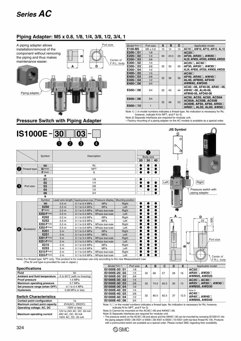
B
DA
Piping adapter
IS1000E 30 03
D
BC
A
E
A piping adapter allows installation/removal of the component without removing the piping and thus makes maintenance easier.
Piping Adapter: M5 x 0.8, 1/8, 1/4, 3/8, 1/2, 3/4, 1
Center ofF.R.L. body
Port size Applicable model
AC10�, AW10, AF10, AR10, AL10
AC20�
AF20, AR20�, AW20�
AL20, AFM20, AFD20, AWM20, AWD20
AC25�, AC30�
AF30, AR30�, AW30�
AL30, AFM30, AFD30, AWM30, AWD30
AC40�
AF40, AR40�, AW40�
AL40, AFM40, AFD40AWM40, AWD40
AC40�-06, AF40-06, AR40�-06, AW40�-06, AL40-06, AFM40-06, AFD40-06
Port size
M5 x 0.8
1/8
1/4
3/8
1/4
3/8
1/2
1/4
3/8
1/2
3/4
3/4
3/4
1
Note 1) � in model numbers indicates a thread type. No indication is necessary for Rc; however, indicate N for NPT, and F for G.
Note 2) Separate interfaces are required for modular unit.∗ Factory mounting of a piping adapter on the AC models is available as a special order.
D14
28
30
36
44
53
B14
23.5
30
36
40
48
A10
30
32
32
32
35
Model Note 1)
E100-M5E200-�01E200-�02E200-�03E300-�02E300-�03E300-�04E400-�02E400-�03E400-�04E400-�06
E500-�06
E600-�06
E600-�10
AC50, AC55, AC60, AC50AAC60A, AC50B, AC55BAC60B, AF50, AF60, AR50�
AR60�, AL50, AL60, AW60�
Pressure Switch with Piping Adapter
JIS Symbol
Pressure switch with piping adapter
Left Right
≈ 5
00
23
Center ofF.R.L. body
Port size
Note 1) � in the model numbers indicates a thread type. No indication is necessary for Rc; however, indicate N for NPT, and F for G.
Note 2) Cannot be mounted on the AC40�-06 and AW40�-06.Note 3) Separate interfaces are required for modular unit.∗ The pressure switch on the AC40�-06 and above and the AW40�-06 can be mounted by screwing IS1000-01 into
the piping adapter E500-�06-X501 or E600-�06-X501 to E600-�10-X501 (with top-face thread Rc 1/8). Products with a premounted switch are available as a special order. Please contact SMC regarding their availability.
Model Note 1)
IS1000E-20�01IS1000E-20�02IS1000E-20�03IS1000E-30�02IS1000E-30�03IS1000E-30�04IS1000E-40�02IS1000E-40�03IS1000E-40�04IS1000E-40�06
Port size
1/8
1/4
3/8
1/4
3/8
1/2
1/4
3/8
1/2
3/4
Applicable model
Note 2)
AC40�
AR40�, AW40�
AWM40, AWD40
A
30
32
32
B
68
74.5
80.5
C
57
60.5
62.5
D
28
30
37
E
16
13
12.5
AC20�
AR20�, AW20�
AWM20, AWD20
AC25�, AC30�
AR25�, AR30�, AW30�
AWM30, AWD30
Specifications
Switch Characteristics
Fluid
Ambient and fluid temperature
Proof pressure
Maximum operating pressure
Set pressure range (when OFF)
Hysteresis
Air
–5 to 60°C (with no freezing)
1.0 MPa
0.7 MPa
0.1 to 0.4 MPa
0.08 MPa or less
Contact point configuration
Maximum contact point capacity
Operating voltage: AC, DC
Maximum operating current
1a
2VA(AC), 2W(DC)
100V or less
12V to 24V AC, DC: 50 mA48V AC, DC: 40 mA100V AC, DC: 20 mA
Note) For thread type: NPT only. This product is for overseas use only according to the new Measurement Law. (The SI unit type is provided for use in Japan.)
+
+
Body sizeDescriptionSymbol
Nil
N Note)
F Note)
Thread type
Rc
NPT
G
0102030406
Port size
1/8
1/4
3/8
1/2
3/4
20 30 40
MPa
MPa
MPa/psi dual scale
MPa/psi dual scale
MPa
MPa
MPa/psi dual scale
MPa/psi dual scale
MPa
MPa
MPa/psi dual scale
MPa/psi dual scale
MPa
MPa
MPa/psi dual scale
MPa/psi dual scale
Right
Left
Right
Left
Right
Left
Right
Left
Right
Left
Right
Left
Right
Left
Right
Left
0.5 m
0.5 m
0.5 m
0.5 m
0.5 m
0.5 m
0.5 m
0.5 m
3 m
3 m
3 m
3 m
3 m
3 m
3 m
3 m
0.1 to 0.4 MPa
0.1 to 0.4 MPa
0.1 to 0.4 MPa
0.1 to 0.4 MPa
0.1 to 0.6 MPa
0.1 to 0.6 MPa
0.1 to 0.6 MPa
0.1 to 0.6 MPa
0.1 to 0.4 MPa
0.1 to 0.4 MPa
0.1 to 0.4 MPa
0.1 to 0.4 MPa
0.1 to 0.6 MPa
0.1 to 0.6 MPa
0.1 to 0.6 MPa
0.1 to 0.6 MPa
Accessory
Regulating pressure range Pressure displayLead wire lengthSymbol Mounting position
Nil
X250P Note)
X250-P Note)
X202X252
X202-P Note)
X252-P Note)
X201X251
X201-P Note)
X251-P Note)
X215X253
X215-P Note)
X253-P Note)
324
Series AC

Y400T
B
C
D
K
D
B
C
H
EE
G
F
Y200T
1
2
Seal
Center of F.R.L. body
X
�������
1
2
A
AJ
Series ACSpacers/Brackets
Accessories
Spacer
Y100
Y200
Y300
Y400
Y500
Y600
Model
AC10, AC10A, AC10B
AC20�
AC25�, AC30�
AC40�
AC40�-06
AC50, AC55, AC60AC50A, AC60AAC50B, AC55B, AC60B
A
6
3
4
5
5
6
B
27
35.5
47
57
61
75.5
C
15
18.5
26
31
33
41
D
33
48
59
65
75
86
Applicable model
Y200 Y400
X-X
(Spacer width)
Description
Seal
Material
HNBR Note 2)
Y100
Y100P-060AS Note 1)
Y200
Y200P-061S
Y300
Y300P-060S
Y400
Y400P-060S
Y500
Y500P-060S
Y600
Y600P-060S
Part no.
Replacement Parts
Spacer with Bracket
øG
Note 1) Assembly of 2 O-rings
Note 2) NBR is used for Y100 spacer because of no direct contact with fluid.
BB
(Y
100T
, Y
200T
only
)
EE
(Y
100T
, Y
200T
only
)
Center of F.R.L. body
Seal
(Spacer width)
X-XX
X
AC10�
AC20�
AC25�, AC30�
AC40�
AC40�-06
AC50, AC55, AC60, AC50A, AC60A, AC50B, AC55B, AC60B
A
6
3
4
5
5
6
B
—
—
82
96
96
120
BB
56
67
—
—
—
—
C
24.5
29
41
48
48
60
D
40.5
53
68
81.5
86
112
E
20
24
35
40
40
50
EE
27
33
—
—
—
—
G
4.5
5.5
7
9
9
11
øG
4.5
5.5
7
9
9
11
Y100T
Y200T
Y300T
Y400T
Y500T
Y600T
Model F
6.8
12
14
18
18
20
J
2.8
3.2
4
4
4.6
6.4
K
25
30
41
50
50
70
H
14
19
21
26
27
31
Applicable model
Description
Seal
Material
HNBR Note 2)
Y100T
Y100P-060AS Note 1)
Y200T
Y200P-061S
Y300T
Y300P-060S
Y400T
Y400P-060S
Y500T
Y500P-060S
Y600T
Y600P-060S
Part no.
Replacement Parts
Note 1) Assembly of 2 O-rings
Note 2) NBR is used for Y100T spacer because of no direct contact with fluid.
�������
325
AC
AF�
AR
AL
AW�
A�G
AV
AF800
AF900

A1A3A2A1 A4
Mounting Position for Spacer with Bracket
A1
—
41.5
55
55
72.5
—
—
—
—
A2
—
43
57
57
75
—
—
—
—
A3
—
43
57
57
75
—
—
—
—
A1
—
41.5
55
55
72.5
77.5
93
98
98
A2
—
43
57
57
75
80
96
96
101
A1
28
41.5
55
55
72.5
77.5
93
98
98
A2
48
61
76
76
99
104
124
124
129
A1
—
41.5
55
55
72.5
77.5
93
—
—
A2
—
43
57
57
75
80
96
—
—
K S T V KS KT KV KSTA3
—
43
57
57
75
80
96
—
—
A1
—
41.5
55
55
72.5
—
—
—
—
A2
—
43
57
57
75
—
—
—
—
A3
—
57
74
74
95
—
—
—
—
A1
—
41.5
55
55
72.5
—
—
—
—
A2
—
61
76
76
99
—
—
—
—
A3
—
43
57
57
75
—
—
—
—
A1
—
41.5
55
55
72.5
—
—
—
—
A2
—
43
57
57
75
—
—
—
—
A3
—
43
57
57
75
—
—
—
—
A4
—
43
57
57
75
—
—
—
—
A1
—
41.5
55
55
72.5
—
—
—
—
A2
—
61
76
76
99
—
—
—
—
A3
—
57
74
74
95
—
—
—
—
AC10AC20AC25AC30AC40
AC40-06AC50AC55AC60
Attachment
Model
A1
—
41.5
55
55
72.5
—
—
—
—
A2
—
43
57
57
75
—
—
—
—
A3
—
57
74
74
95
—
—
—
—
A4
—
43
57
57
75
—
—
—
—
A1
—
41.5
55
55
72.5
—
—
—
—
A2
—
61
76
76
99
—
—
—
—
A3
—
43
57
57
75
—
—
—
—
A4
—
43
57
57
75
—
—
—
—
A1
—
41.5
55
55
72.5
—
—
—
—
KSV KTV KSTV ST SV STV TVA2
—
61
76
76
99
—
—
—
—
A3
—
57
74
74
95
—
—
—
—
A4
—
43
57
57
75
—
—
—
—
A1
—
41.5
55
55
72.5
77.5
93
98
98
A2
—
61
76
76
99
104
124
124
129
A1
—
41.5
55
55
72.5
77.5
93
—
—
A2
—
43
57
57
75
80
96
—
—
A3
—
57
74
74
95
102
124
—
—
A1
—
41.5
55
55
72.5
77.5
93
—
—
A2
—
61
76
76
99
104
124
—
—
A3
—
57
74
74
95
102
124
—
—
A1
—
41.5
55
55
72.5
77.5
93
—
—
A2
—
61
76
76
99
104
124
—
—
A3
—
43
57
57
75
80
96
—
—
AC10AC20AC25AC30AC40
AC40-06AC50AC55AC60
Attachment
Model
A1
—
41.5
55
55
72.5
77.5
93
98
98
A1
28
41.5
55
55
72.5
77.5
93
98
98
A1
—
41.5
55
55
72.5
77.5
93
—
—
A2
—
43
57
57
75
80
96
—
—
A1
—
41.5
55
55
72.5
77.5
93
—
—
A2
—
57
74
74
95
102
124
—
—
A1
—
41.5
55
55
72.5
77.5
93
—
—
A2
—
61
76
76
99
104
124
—
—
TS TVSVA1
—
41.5
55
55
72.5
77.5
93
—
—
A2
—
43
57
57
75
80
96
—
—
V1A1
—
41.5
55
55
72.5
77.5
93
—
—
A2
—
43
57
57
75
80
96
—
—
SV1A1
—
41.5
55
55
72.5
77.5
93
—
—
A2
—
43
57
57
75
80
96
—
—
TV1V
AC10BAC20BAC25BAC30BAC40B
AC40B-06AC50BAC55BAC60B
Attachment
Model
A1
41.5
55
72.5
—
—
—
A2
43
57
75
—
—
—
A1
41.5
55
72.5
77.5
98
98
A1
41.5
55
72.5
77.5
98
—
A2
43
57
75
80
96
—
A1
41.5
55
72.5
—
—
—
A2
57
74
95
—
—
—
A1
41.5
55
72.5
—
—
—
A2
43
57
75
—
—
—
K KSVS KV KSV SVA3
43
57
75
—
—
—
A1
41.5
55
72.5
—
—
—
A2
57
74
95
—
—
—
A3
43
57
75
—
—
—
A1
41.5
55
72.5
77.5
98
—
A2
57
74
95
102
124
—
AC20AAC30AAC40A
AC40A-06AC50AAC60A
Attachment
Model
A1
41.5
55
55
72.5
77.5
A2
43
57
57
75
80
A1
41.5
55
55
72.5
77.5
A2
43
57
57
75
80
A1
41.5
55
55
72.5
77.5
A2
43
57
57
75
80
A3
43
57
57
75
80
A1
41.5
55
55
72.5
77.5
A2
43
57
57
75
80
S VT V1 TVSV1 TV1A3
43
57
57
75
80
A1
41.5
55
55
72.5
77.5
A2
43
57
57
75
80
SVA3
57
74
74
95
102
A1
41.5
55
55
72.5
77.5
A2
43
57
57
75
80
A3
61
76
76
99
104
A1
41.5
55
55
72.5
77.5
A2
43
57
57
75
80
A3
43
57
57
75
80
A1
41.5
55
55
72.5
77.5
A2
43
57
57
75
80
A3
43
57
57
75
80
AC20CAC25CAC30CAC40C
AC40C-06
Attachment
Model
A1
41.5
55
72.5
77.5
A1
41.5
55
72.5
77.5
A2
43
57
75
80
A1
41.5
55
72.5
77.5
A2
43
57
75
80
S V1A1
41.5
55
72.5
77.5
A2
57
74
95
102
SVVA1
41.5
55
72.5
77.5
A2
43
57
75
80
SV1
AC20DAC30DAC40D
AC40D-06
Attachment
Model
A1: Dimensions from the end of the IN side to the center of the mounting hole
for the first bracket.
A2: Mounting hole pitch between the first and the second brackets.
A3: Mounting hole pitch between the second and the third brackets.
A4: Mounting hole pitch between the third and the fourth brackets.
3-port valve for residual pressure: V
Check valve: KPressure switch: ST-interface: T
IN OUT
Bracket
IN OUT
Bracket
SUP.
326
Series AC

P.G. Information
Epoxy Coated F.R.L.Units
AC21/31/41-***-*-X2217AF20/30/40-***-*-X480AR20/30/40-***-*-X48AL20/30/40-***-*-X480AW20/30/40-***-*-X48VHS20/30/40-***-*-X513Y20/30/40*-T4
Application: Air preparation in an environment that requires enhanced corrosion protection.
Feature 1: Die cast aluminum components are epoxy coated for improved chemical resistance.
Feature 2: Steel external hardware is replaced with stainless steel for improved chemicalresistance.
Comparison with Standard Product:
1) Functional performance is equivalent to standard product.
2) Product withstood salt spray testing per ASTM B117-07A with excellent results(See test results on page 12). Improved performance vs. other chemicals isanticipated but has not been verified.
Applications:
• Marine environments
• Water splash zone in various processes
• Washdown in food plants (non-food or splash zone only)
Related Products:
• KQG Series - 316 SUS One-touch Fittings - Coming Soon: KQG2
• KQB2 Series - Ni plated brass One-touch Fittings (Coming Soon)
• ASG Series - 316 SUS One-touch Speed Controls
• CG5 Series - repairable 304 SUS Cylinder
• NCM Series with X6009 option - crimped body 304 SUS Cylinder, domesticinterchange
• CJ5 Series - crimped body 304 SUS Cylinder
• HY Series - Aluminum body Hygienic Design Actuators
SP093-001I
Issued: Sep 2009
SMC Corporation of America10100 SMC BoulevardNoblesville, IN 46060
www.smcusa.com

Series AC21~41F.R.L. Unit
2
How To Order
AC 31 B N 03 D V 8 Y Z - X2217— — —
Air Combination Unit
Note: Other sizes, thread forms, options, etc. may be possible,please contact SMC for availability.
With External Epoxy Coating, Stainless Fasteners
Name Plate, Caution Plate On Bowl in psi, ˚F
NPT Threads
Body SizeSymbol
213141
Size1/83/81/2
Model CombinationSymbol
NilAB
Model / Assembly OrderAF + AR + ALAW + ALAF + AR
Port SizeSymbol
020304
Port Size1/43/81/2
Applicable Body Size213141
SpecificationsBody sizeOperating specificationsPort sizeAuto drain port (AF, AW)Bowl type (AF, AL, AW)Body materialBowl material (AF, AL, AW)Body, Bowl surface treatmentBonnet (AR, AW)Manual drain (AF, AW)External screwsIndividual mounting bracketsPanel mount nut (AR, AW)Connector brackets (AC)Fill plug (AL)Sight dome (AL)Sightglasshardware (AF,AL,AW)
21 31 41
AC21AC31AC41
AC A*140181238
AA**190245322
B160220239
C738692
E—3038
F45.558.575.5
G405580
J2629.537.5
K53.51.5
M304150
N516481
Q243540
U577
V334550
W—34.541
Same as standard - see catalog ES40-42D or NC160A1/4” NPTN/AMetal
1/4” NPTMetal with sight gauge
Die cast aluminumDie cast aluminumEpoxy resin coating
PolyacetalPOM
Stainless steel 410Epoxy coated steel
POMDie cast zinc (epoxy coated)
Stainless steel 304Polycarbonate
Stainless steel 304
3/8” NPT 1/2” NPT
BowlSymbol
28
DescriptionMetal Bowl
Metal Bowl With Sight Glass
Applicable Body Size21
31, 41
Residual Pressure Relief ValveSymbol
NilV
DescriptionWithout Valve
With Downstream Valve
Applicable Model ComboAllAll
AccessoriesSymbol
NilCD
DescriptionNone
Float Auto Drain (N.C.)Float Auto Drain (N.O.)
Applicable Body SizeAll
31, 4131, 41
Regulator Handle OrientationSymbol
NilY
DescriptionDownward HandleUpward Handle
Dimensions - Refer to drawings on page 3 mm
AC21AAC31AAC41A
A*90117154
AA**140181238
B160220239
C738692
E—3038
F45.558.575.5
G405580
J2629.537.5
K53.51.5
M304150
N516481
Q243540
U577
V334550
W—34.541
mm
AC21BAC31BAC41B
A*90117154
AA**140181238
B160220239
C738692
E—3038
F45.558.575.5
G405580
J2629.537.5
K53.51.5
M304150
N516481
Q243540
U577
V334550
W—34.541
mm
AC-A
AC-B
* Without relief valve option ** With relief valve option
* Without relief valve option ** With relief valve option
* Without relief valve option ** With relief valve option

3
Series AC21~41 F.R.L. UnitAC AA
NF
C
B
E
G
K
W
U
QQV
M J
(2) - P1(Port Size)
P2(GaugePort Size)
Min
.Cle
aran
ceF
or
Mai
nte
nan
ce
IN OUT
Bracket andRelief Valve(Optional)
A
AC-A AA
NF
C
B
EG
K
W
U
QQV
M J
(2) - P1(Port Size)
P2(GaugePort Size)
Min
.Cle
aran
ceF
or
Mai
nte
nan
ce
IN OUT
A
Bracket andRelief Valve(Optional)
AC-B AA
NF
CB
E
G
K
W
U
QQV
M J
(2) - P1(Port Size)
P2(GaugePort Size)
Min
.Cle
aran
ceF
or
Mai
nte
nan
ce
IN OUT
Bracket andRelief Valve(Optional)
A
Note: Sight glass notapplicable to all size 20bowls.
Notes: Filter & Filter Regulator Bowls depict manual drain, see individual sections for details with auto-drain options.
D
Bowl Detail(AF20/AW20)

4
Series AF20~40FilterHow To Order
AF 30 N 03 D 8 Z - X480— —
Filter
Note: Other sizes, thread forms, options, etc. may be possible,please contact SMC for availability. *Note: Bracket is not assembled and is supplied loose at time of shipment.
With External Epoxy Coating, Stainless Fasteners
Name Plate, Caution Plate On Bowl in psi, ˚F
NPT Threads
Body SizeSymbol
203040
Size1/83/81/2
Port SizeSymbol
020304
Port Size1/43/81/2
Applicable Body Size203040
SpecificationsBody sizeOperating specificationsPort sizeAuto drain portBowl typeBody materialBowl materialBody, Bowl surface treatmentManual drain (AF, AW)External screwsIndividual mounting bracketsSight glass hardware
20 30 40
AF20AF30AF40
ANPT 1/4NPT 3/8NPT 1/2
C405370
Same as standard - see catalog ES40-42D or NC160A1/4” NPTN/AMetal
1/4” NPTMetal with sight gauge
Die cast aluminumDie cast aluminumEpoxy resin coating
POMStainless steel 410Epoxy coated steelStainless steel 304
3/8” NPT 1/2” NPT
BowlSymbol
28
DescriptionMetal Bowl
Metal Bowl With Sight Glass
Applicable Body Size20
30, 40
AccessoriesSymbol
NilB*CD
DescriptionNone
Mounting BracketFloat Auto Drain (N.C.)Float Auto Drain (N.O.)
Applicable Body SizeAllAll
30, 4030, 40
Dimensions Mounting Bracket Kit(Optional)
AF20P-050AS-X480AF30P-050AS-X480AF40P-050AS-X480
ModelPort Size
D97149185
E101418
F405370
G—5773
H181617
J304150
K274054
L222326
M5.46.58.5
N8.4810.5
P405370
Q2.32.32.3
R263547
S324460
W—34.541
TM4 X 0.7M4 X 0.7M5 X 0.8
AF30AF40
ANPT 3/8NPT 1/2
C5370
Dimensions Mounting Bracket Kit(Optional)
AF30P-050AS-X480AF40P-050AS-X480
ModelPort Size
D158194
E1418
F5370
G5773
H1617
J4150
K4054
L2326
M6.58.5
N810.5
P5370
Q2.32.3
R3547
S4460
W34.541
TM4 X 0.7M5 X 0.8
Auto Drain
Standard
Dimensions - Refer to drawings on page 5
mm
mm

5
Series AF20~40 FilterStandard(Manual Drain)
RC
4 - TBRACKETMOUNTING THREAD
S F
WM
IN OUT
PKN 2 - A
U
D
GJ Q
HLE
Bracket(Optional)
With Auto Drain
RC
4 - TBRACKETMOUNTING THREAD
S F
WM
IN OUT
PKN 2 - A
D
GJ Q
H
LE
NPT 1/4
Bracket(Optional)
D
Note: Sight glass notapplicable to AF20.
Bowl Detail U(AF20)
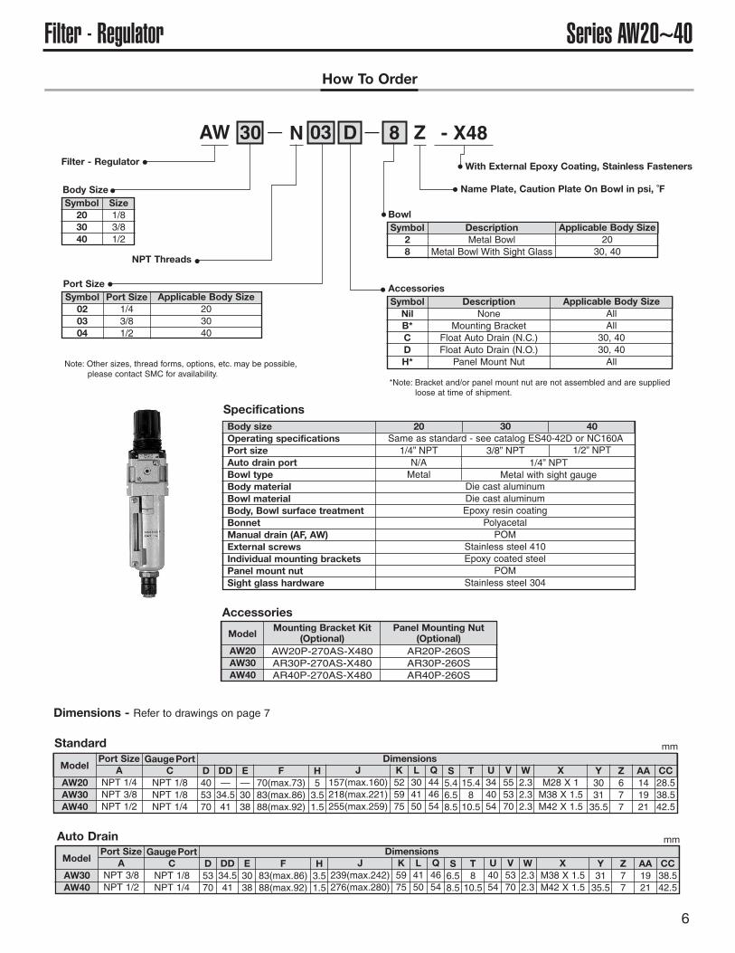
6
Series AW20~40Filter - RegulatorHow To Order
AW 30 N 03 D 8 Z - X48— —
Filter - Regulator
Note: Other sizes, thread forms, options, etc. may be possible,please contact SMC for availability.
With External Epoxy Coating, Stainless Fasteners
Name Plate, Caution Plate On Bowl in psi, ˚F
NPT Threads
Body SizeSymbol
203040
Size1/83/81/2
Port SizeSymbol
020304
Port Size1/43/81/2
Applicable Body Size203040
SpecificationsBody sizeOperating specificationsPort sizeAuto drain portBowl typeBody materialBowl materialBody, Bowl surface treatmentBonnetManual drain (AF, AW)External screwsIndividual mounting bracketsPanel mount nutSight glass hardware
20 30 40Same as standard - see catalog ES40-42D or NC160A1/4” NPTN/AMetal
1/4” NPTMetal with sight gauge
Die cast aluminumDie cast aluminumEpoxy resin coating
PolyacetalPOM
Stainless steel 410Epoxy coated steel
POMStainless steel 304
3/8” NPT 1/2” NPT
BowlSymbol
28
DescriptionMetal Bowl
Metal Bowl With Sight Glass
Applicable Body Size20
30, 40
AccessoriesSymbol
NilB*CDH*
DescriptionNone
Mounting BracketFloat Auto Drain (N.C.)Float Auto Drain (N.O.)Panel Mount Nut
Applicable Body SizeAllAll
30, 4030, 40All
AW30AW40
ANPT 3/8NPT 1/2
DimensionsModel
Port SizeC
NPT 1/8NPT 1/4
GaugePortD5370
DD34.541
E3038
F83(max.86)88(max.92)
H3.51.5
J239(max.242)276(max.280)
K5975
L4150
Q4654
S6.58.5
U4054
T810.5
V5370
W2.32.3
XM38 X 1.5M42 X 1.5
Y3135.5
Z77
AA1921
CC38.542.5
AW20AW30AW40
ANPT 1/4NPT 3/8NPT 1/2
DimensionsModel
Port SizeC
NPT 1/8NPT 1/8NPT 1/4
GaugePortD405370
DD—34.541
E—3038
F70(max.73)83(max.86)88(max.92)
H53.51.5
J157(max.160)218(max.221)255(max.259)
K525975
L304150
Q444654
S5.46.58.5
U344054
T15.4810.5
AW20AW30AW40
Mounting Bracket Kit(Optional)
AW20P-270AS-X480AR30P-270AS-X480AR40P-270AS-X480
Model
V555370
W2.32.32.3
XM28 X 1M38 X 1.5M42 X 1.5
Y303135.5
Z677
AA141921
CC28.538.542.5
Panel Mounting Nut(Optional)
AR20P-260SAR30P-260SAR40P-260S
Auto Drain
Standard
Accessories
Dimensions - Refer to drawings on page 7
mm
mm
*Note: Bracket and/or panel mount nut are not assembled and are suppliedloose at time of shipment.

7
Series AW20~40 Filter - RegulatorStandard(Manual Drain)
C
IN OUT
2 - A
H
IN OUT
AA
Z CC
PANEL FITTING
DD
E EE
J
Y QF
W
KL
X
VU
TS
D
Bracket andMounting Nut(Optional)
With Auto Drain
C
IN OUT
2 - A
H
IN OUT
AA
Z CC
PANEL FITTING
DD
E
J
Y QF
W
KL
X
VU
T
S
D
Bracket andMounting Nut(Optional)
J
Bowl Detail EE(AW20)
Note: Sight glass notapplicable to AW20.

8
Series AR20~40RegulatorHow To Order
AR 20 N 02 B Y Z - X48— —
Regulator
Note: Other sizes, thread forms, options,etc. may be possible, pleasecontact SMC for availability.
With External Epoxy Coating, Stainless Fasteners
Name Plate, Caution Plate On Bowl in psi, ˚F
NPT Threads
Body SizeSymbol
203040
Size1/83/81/2
Port SizeSymbol
020304
Port Size1/43/81/2
Applicable Body Size203040
SpecificationsBody sizeOperating specificationsPort sizeBody materialBody, Bowl surface treatmentBonnetIndividual mounting bracketsPanel mount nut
20 30 40Same as standard - see catalog ES40-42D or NC160A1/4” NPT
Die cast aluminumEpoxy resin coating
PolyacetalEpoxy coated steel
POM
3/8” NPT 1/2” NPT
Handle OrientationSymbol
NilY
DescriptionHandle DownHandle Up
AccessoriesSymbol
NilB*H*
DescriptionNone
Mounting BracketPanel Mount Nut
AR20AR30AR40
ANPT 1/4NPT 3/8NPT 1/2
DimensionsModel
Port SizeC
NPT 1/8NPT 1/8NPT 1/4
GaugePortD405370
E575968
F26.53136
H-23.53.5
J91(max.94)113(max.116)124(max.128)
K304150
L656674
M37.537.542.5
P444654
S15.4810.5
Q5.46.58.5
AR20AR30AR40
Mounting Bracket Kit(Optional)
AR20P-270AS-X48AR30P-270AS-X48AR40P-270AS-X48
Model
T344054
U555370
WM28 X 1M38 X 1.5M42 X 1.5
X677
Y141921
Z28.538.542.5
AA253135.5
Panel Mounting Nut(Optional)
AR20P-260SAR30P-260SAR40P-260S
V2.32.32.3
C
IN OUT
2 - AH
IN OUT
AA
X Z
PANEL FITTING
E
J
Y
Q
F
W
K
V
UT
S
D
P
Plate ThicknessAR20, 30: Max 3.5AR40: Max 5
Bracket andMounting Nut(Optional)
Dimensions
Accessories
mm
*Note: Bracket and/or panel mount nut arenot assembled and are suppliedloose at time of shipment.

9
Series AL20~40 LubricatorHow To Order
AL 20 N 02 B 2 Z - X480— —Lubricator
Note: Other sizes, thread forms, options, etc. may be possible, please contact SMC for availability.
With External Epoxy Coating,Stainless Fasteners
Name Plate, Caution PlateOn Bowl in psi, ˚F
NPT Threads
Body SizeSymbol
203040
Size1/83/81/2
Port SizeSymbol
020304
Port Size1/43/81/2
Applicable Body Size203040
BowlSymbol
28
DescriptionMetal Bowl
Metal Bowl With Sight Glass
Applicable Body Size20
30, 40
AccessoriesSymbol
NilB*
DescriptionNone
Mounting Bracket
Applicable Body SizeAllAll
Specifications
Dimensions
Body sizeOperating specificationsPort sizeBowl typeBody materialBowl materialBody, Bowl surface treatmentIndividual mounting bracketsFill plugSight domeSight glass hardware
20 30 40Same as standard - see catalog ES40-42D or NC160A1/4” NPTMetal
Die cast zincMetal with sight gaugeDie cast aluminum
Die cast aluminumEpoxy resin coatingEpoxy coated steelStainless steel 304Polycarbonate
Stainless steel 304
3/8” NPT 1/2” NPT
AL20AL30AL40
ANPT 1/4NPT 3/8NPT 1/2
C405370
Dimensions Mounting Bracket Kit(Optional)
AF20P-050AS-X480AF30P-050AS-X480AF40P-050AS-X480
ModelPort Size
D121162196
E363840
F405370
G—5773
H283035
J304150
K274054
L222326
M5.46.58.5
N8.4810.5
P405370
Q2.32.32.3
R263547
S324460
W—34.541
TM4 X 0.7M4 X 0.7M5 X 0.8
RC
4 - TBRACKETMOUNTING THREAD
S F
WM
IN OUT
PK
N 2 - A
D
GJ
Q
HL
E
1
23
456
78
9
Bracket(Optional)
Sight glassassy notapplicableto AL20
mm
*Note: Bracket is not assembled and is supplied loose at time of shipment.

10
Accessories
Note: Other sizes, thread forms, options, etc. may be possible,please contact SMC for availability.
C
Ø1
Lockable at the time of exhaust
F
IN OUT
B
D
GH
A
E
EXH
2-Ø10
VHS20VHS30VHS40
IN, OUT1/43/81/2
IN to OUT14 (0.76)31 (1.68)55 (2.98)
OUT to EXH16 (0.87)29 (1.57)42 (2.28)
Effective area mm2 (Cv)Model
Port SizeEXH1/81/43/8
VHS20VHS30VHS40
5978107
Model A
Paint color (Standard) Handle: Red Body: Platinum silverUse an air filter on the IN side for operating protection.
If a stop valve or a silencer is connected to the exhaust port of VHS20/30,the effective sectional area should be larger than the figure indicated in thefollowing table, to prevent malfunction caused by back pressure. (This isnot applicable to VHS40)
If unit is to be used in a washdown application, avoid directing fluidinto the exhaust port.
With the use of a 3 port valve for residual pressure release, pressure left in theline can be easily exhausted.
Residual Pressure Relief 3 Port Valve (V)
JIS Symbol(A)
(P) (R)
2
1 3
202939
405370
344663
——22
455558
334244
283036
455563
B C D E F G H I
Caution
ModelVHS20VHS30
Effective area (mm2)55
How To Order
VHS 30 N 02 Z - X513— —
With ExternalEpoxyCoating,StainlessFasteners
Name Plate InImperial Units(PSI, ˚F)
ResidualPressure Relief3 Port Valve
Body SizeSymbol
203040
Applicable ModelAC21AC31AC41
Body Size
Symbol Port Size Body Size20 30 40
020304
1/43/81/2
Thread TypeN NPT
Dimensions mm

Y20T-T4Y30T-T4Y40T-T4
A B C D E F G H R L Applicable ModelsInterface
With TBracket
243540
151622
5.579
344
304150
577
101114
487080
2.753.54.5
334550
AC21*-X2217AC31*-X2217AC41*-X2217
Interface withT-type bracket
F
B
D
G
H
L
E
T-type bracket
F.R.L. Body center
RA
C
Epoxy Coated Aluminum, Stainless Screws,NBR Seals
Interface With T Bracket
Epoxy Coated Aluminum,Stainless Screws,NBR Seals
Spacer
Dimensions
(N)AV
AMG
AR20-60
AVL
AW20-40
E*00
Y*10
Y*4
Soft Start Valve
Water Removal Filter
Regulator with Stainless T-handle, aluminum bonnet for UV resistance
Soft Start Valve with Pilot Lock-Out
Filter-Regulator with Stainless T-handle, aluminum bonnet for UV resistance
Piping Adapter
T Interface
Cross Interface
X480
X229
X480
X480
X480
X480
X480
T3
Description Option CodeSeries
Other Available Air Line Products with Epoxy Coating/Stainless Hardware
mm
11
Accessories
F.R.L. center
Y20-T4Y30-T4Y40-T4
101114
Model A
Dimensionsmm
Please contact SMC for ordering information

12
Salt Spray Test Results (for reference)1. Test Conditions
1) Method: In compliance with ASTM B117-07a (JIS Z 2371), leave parts in a salt spray testchamber, and compare rust generation.
2) Conditions: Temperature: 95˚F (35˚C) Salt Water Concentration: 5%
3) Time: 1000 hours [Frequency: 0hr, 24hrs, 48hrs, 72hrs, 96hrs, 168hrs, 240hrs, 480hrs, 720hrs, 1000hrs]
4) Samples: Parts for AF and AW30 (See Figure 1.)
• Part descriptions: 4 parts (1) Body (2) Drain cock (3) Small screw for level gauge (4) Bonnet screw
•Types: 2 Types A) Standard B) Special X480 (Coated with epoxy resin [External metal parts are made of SUS])
• Refer to Table 1 for part materials and treatments. *Quantity; 2 pieces for each
2. Test Results Table 1 Salt spray resistance test results
Body Screw
Drain Cock
Standard X480 Epoxy Resin Coating Standard X480 Stainless Steel
Standard X480 Stainless Steel
Figure 1
1A
B
A
B
A
B
A
B
Standard
Special X480
Standard
Special X480
Standard
Special X480
Standard
Special X480
Material: Die Cast AluminumTreatment: Platinum CoatingMaterial: Die Cast Aluminum
Treatment: Platinum & Epoxy Coating
Material: Die Cast AluminumTreatment: Zinc Chromate
Rusted in 480hrsPart of coating swelledNot rusted in 1000hrsPart of coating swelled
Rusted in 24hrs
Not rusted in 1000hrs
Not rusted in 1000hrs
Not rusted in 1000hrs
Rusted in 24hrs
Rusted in 24hrsMaterial: SteelTreatment: Zinc Chromate
Material: SteelTreatment: Nickel Plating
Material: SUS
Material: SUS
Material: SUS
Body
Drain cock2
3
Cross recessedround head
screw formetalbowl with level
gauge
Self-tappingscrew for ARand AWbonnet
4
No. Description Type Material & Treatment Results
2
3
1
4
Caution! To ensure the safest possible operation of this product, please be sure to read thoroughlythe “Safety Instructions” in our “Best Pneumatics” catalog before use.
©2009 SMC Corporation All Rights Reserved